ptc thermistors as self-regulating heating elements bound... · 170 philips technical review volume...
TRANSCRIPT
170 PHILIPS TECHNICAL REVIEW VOLUME 30
PTC thermistors as self-regulating heating elements
E. Andrich
The resistance of PTe thermistors varies with temperature in such a way that they can beused as heating elements with particularly interesting characteristics. When a sufficientlylarge voltage is used, they reach a temperature near their ferroelectric Curie point with ahigh initial current in a few seconds, assume a high value of resistance at this temperatureand act from then on like thermostats. These heating elements thus automatically regulatetheir power consumption to suit the heat requirements. Investigations with laboratorymodels of soldering irons and domestic hotplates have given impressive demonstrations ofthe special advantages of these elements.
Introduetion
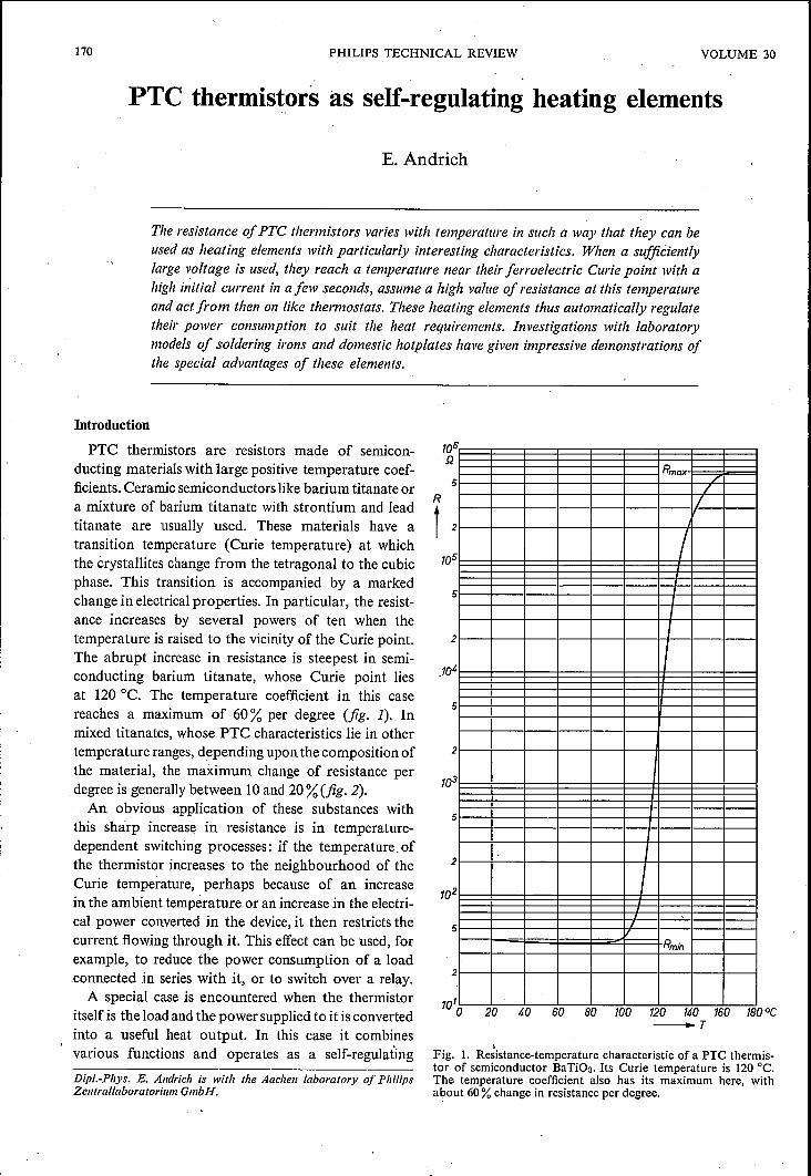
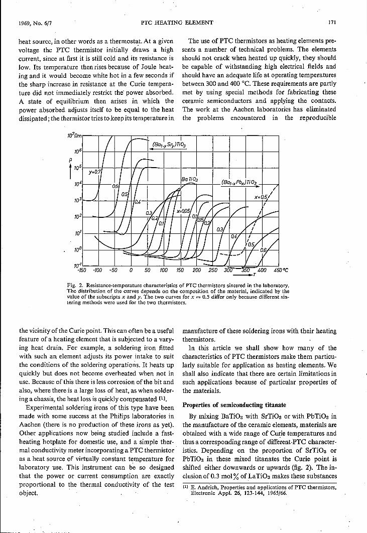
PTC thermistors are resistors made of semicon-ducting materials with large positive temperature coef-ficients. Ceramic semiconductors like barium titanate ora mixture of barium titanate with strontium and leadtitanate are usually used. These materials have atransition temperature (Curie temperature) at whichthe crystallites change from the tetragonal to the cubicphase. This transition is accompanied by a markedchange in electrical properties. In particular, the resist-ance increases by several powers of ten when thetemperature is raised to the vicinity of the Curie point.The abrupt increase in resistance is steepest in semi-conducting barium titanate, whose Curie point liesat 120°C. The temperature coefficient in this casereaches a maximum of 60% per degree (fig. 1). Inmixed titanates, whose PTC characteristics lie in othertemperature ranges, depending upon the composition ofthe material, the maximum change of resistance perdegree is generally between 10and 20% (fig. 2).An obvious application of these substances with
this sharp increase in resistance is in temperature-dependent switching processes: if the temperature, ofthe thermistor increases to the neighbourhood of theCurie temperature, perhaps because of an increasein the ambient temperature or an increase in the electri-cal power converted in the device, it then restricts thecurrent flowing through it. This effect can be used, forexample, to reduce the power consumption of a loadconnected in series with it, or to switch over a relay.A special case is encountered when the thermistor
itself is the load and the power supplied to it is convertedinto a useful heat output. In this case it combinesvarious functions and operates as a self-regulatingDipl-Phys. E. Andrich is with the Aachen laboratory of PhilipsZentrallaboratorium GmbH.
Rmax7/
1£
I1
15
Rmin
1
5
5
2
5
2
5
2
2
100 20 40 60 80 100 120 140 160 180oe-T
Fig. 1. Re~istance-temperature characteristic of a PTC thermis-tor of semiconductor BaTiOa. Its Curie temperature is 120°C.The temperature coefficient also has its maximum here, withabout 60% change in resistance per degree.
1969, No. 6/7 PTC HEATING ELEMENT 171
I /I---- 1 .1
(Ba,_ySry) Tt03
I I r:;--Y=O.~ I 1/ / Ba!f_03 (Ba,_xPbx)Ti 03D,, sf I A /
J 0.5 v- Ix=as/~)I/ 1(·4 /J '/ Ix=aos!n!( / ?.: I
Q3 j IL,...--
-Ij J 1ïl I / jQ?f Q3//(
1/ 0.1
/ /"'\r-, V Vj / / / 1/ / / I
~~-;::::" ./ ./ .LLV j-i ,/ / as_ ....
1-::-1'So -100 -50 0 50 100 150 200 250 30o -:350 400 45
heat source, in other words as a thermost~t. At a givenvoltage the PTC thermistor initially draws a highcurrent, since at first it is still cold and its resistance islow. Its temperature thenrises because of Joule heat-ing and it would become white hot in a few seconds ifthe sharp increase in resistance at the Curie tempera-ture did not immediately restrict the' power absorbed.A state of equilibrium then arises in which thepower absorbed adjusts itself to be equal to the heatdissipated; the thermistor tries to keep its temperature in
10
The use of PTC thermistors as heating elements pre-sents a number of technical problems. The elementsshould not crack when heated up quickly, they shouldbe capable of withstanding high electrical fields andshould have an adequate life at operating temperaturesbetween 300 and 400°C. These requirements are partlymet by using special methods for fabricating theseceramic semiconductors and applying the contacts.The work at the Aachen laboratories has eliminatedthe problems encountered in the reproducible
_T
Fig. 2. Resistance-temperature characteristics of PTC thermistors sintered in the laboratory.The distribution of the curves depends on the composition of the material, indicated by thevalue of the subscripts x and y. The two curves for x = 0.5 differ only because different sin-tering methods were used for the two thermistors.
the vicinity ofthe Curie point. This can often be a usefulfeature of a heating element that is subjected to a vary-ing heat drain. For example, a soldering iron fittedwith such an element adjusts its power intake to suitthe conditions of the soldering operations, It heats upquickly but does not become overheated when not inuse. Because ofthis there is less corrosion ofthe bit andalso, where there is a large loss of heat, as when solder-ing a chassis, the heat loss is quickly compensated [11.
Experimental soldering irons of this type have beenmade with some success at the Philips laboratories inAachen (there is no production of these irons as yet).Other applications now being studied include a fast-heating hotplate for domestic use, and a simple ther-mal conductivity meter incorporating a PTC thermistoras a heat source of virtually constant temperature forlaboratory use. This instrument can be so designedthat the power or current consumption are exactlyproportional to the thermal conductivity of the testobject.
manufacture of these soldering irons with their heatingthermistors.In this article we shall show how many of the
characteristics of PTC thermistors make them particu-larly suitable for application as heating elements. Weshall also indicate that there are certain limitations insuch applications because of particular properties ofthe materials.
Properties of semiconducting titanate
By mixing BaTiOa with SrTiOa or with PbTiOa inthe manufacture of the ceramic elements, materials areobtained with a wide range of Curie temperatures andthus a corresponding range of different-P'ï'C character-istics. Depending on the proportion of SrTiOa orPbTiOa in these mixed titanates the Curie point isshifted either downwards or upwards (fig. 2). The in-clusion of 0.3 mol % of LaTiOa makes these substances[1] E. Andrich, Properties and applications of PTC thermistors,
Electronic Appl. 26, 123-144, 1965/66.
172 PHILlPS TECHNICAL REVIEW VOLUME 30
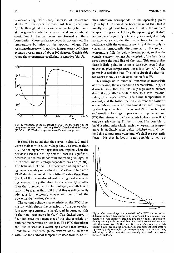
semiconducting. The sharp increase of resistanceat the Curie temperature does not take place uni-formly throughout the whole ceramic body but onlyat the grain boundaries between the densely sinteredcrystallites [21. Barrier layers are formed at theseboundaries, whose resistance depends not only on thetemperature but also on the applied voltage. Theresistance increase with positive temperature coefficientextends over a range of about 100degrees. Outside thisrange the temperature coefficient is negative (fig. 3).
(- ----... r-,/ <,
1\ I-. )l-
t100 200 300o -- ... r
Fig. 3. Variation of the resistance R of a PTC thermistor in thetemperature range from -100 to +390°C. Outside the PTC range(50°C to 180 "C) the temperature coefficient is negative.
It should be noted that the curves in figs. 1, 2 and 3were obtained with a test voltage that was smaller than2 V. At the higher voltages that are applied when thedevice is used as a heating element there is a significantdecrease in the resistance with increasing voltage, asin the well-known voltage-dependent resistor (VDR).The behaviour of the PTC thermistor at higher volt-ages can be readily understood if it is assumed to have aVDR shunted across it. The resistance ratio Rmax/Rmln(fig. 1) of the thermistor whenitis being used as a heat-ing element may therefore be considerably smallerthan that observed at the test voltage; nevertheless itcan still be greater than 100:1, and this is still perfectlyadequate for temperature-dependent control of thepower in the heating element.
The current-voltage characteristic of the PTC ther-mistor, which shows the behaviour of the device whenit is carrying a current, is therefore of importance; thisis; the non-linear curve in fig. 4. The dashed curve infig. 4 indicates the dependence of this characteristic onambient temperature or heat loss. The PTC thermistorcan thus be used às a switching element that severelylimits the current through the resistive load R in serieswith it as the ambient temperature rises from Tl to T2.
This situation corresponds to the operating pointP2' in fig. 4. It should be borne in mind that this isusually a single switching process; when the ambienttemperature goes back to Tl the operating point doesnot go back beyond P2. Generally speaking, it is onlypossible to switch the thermistor back to the coldresistance with the operating point PI if the supply ofcurrent is temporarily disconnected or the ambienttemperature falls far below freezing point, so that thecomplete current-voltage characteristicofthe thermistorrises above the load-line of the load. This means thatthere is little point in using a series-connected ther-mistor to give temperature-dependent control of thepower in a resistive load. In such a circuit the thermis-tor works merely as a delayed-action fuse [11.
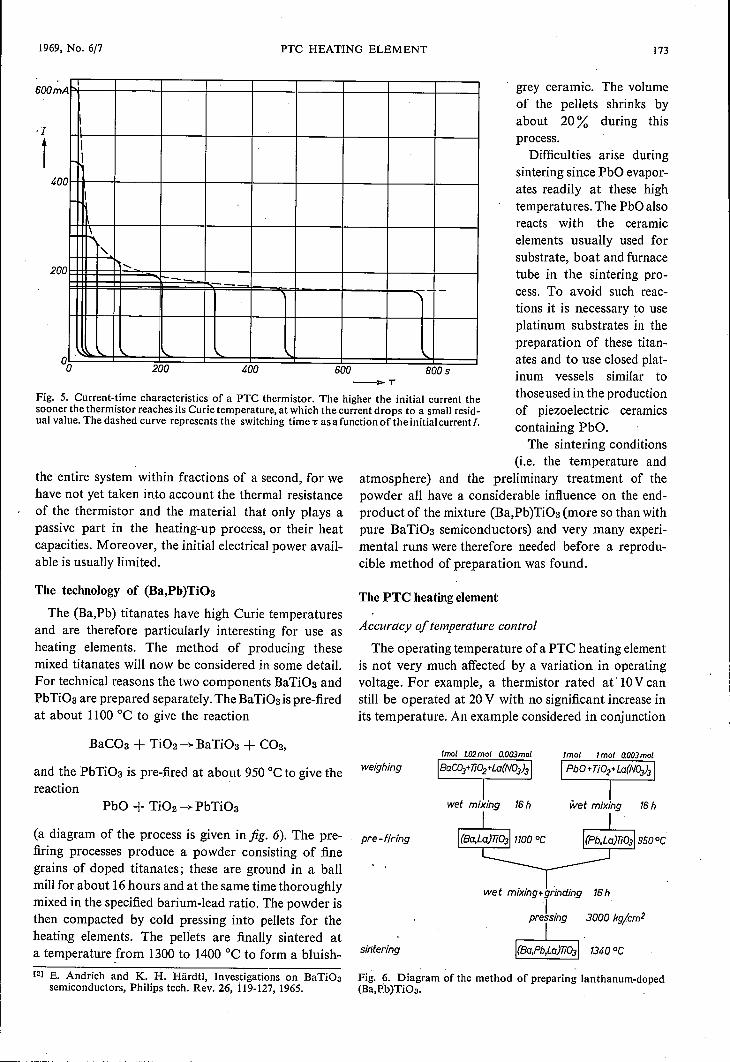
This brings us to another important characteristicof this device, the current-time characteristic. In fig. 5it can be seen that the relatively high initial currentdrops steeply after a certain time to a low residualvalue; this happens when the Curie temperature isreached, and the higher the initial current the earlier itoccurs. Measurements of this time show that it may beas short as a fraction of a second [11. If such shortself-arresting heating-up processes are possible, andPTC thermistors with Curie points higher than 400 °Ccan be made (see fig. 2), then it should be possible tobuild heating units which reach their operating temper-ature immediately after being switched on and thenhold this temperature constant. We shall see presently(page 174) that in fact it is not possible to heat up
I
I
Fig. 4. Current-voltage characteristic of a PTC thermistor atdifferent ambient temperatures Tl and T2. At low ambient tem-perature Tl the characteristic has two stable points of intersec-tion P; and P2 with the load-line of a load R connected in serieswith the thermistor. At the operating point Pi a relatively highcurrent flows through the circuit. At higher ambient temperatureT2 there is only one point of intersection P2' at a low current,indicating that the thermistor has severely restricted the currentthrough the load.
1969, No. 6/7 PTC HEATING ELEMENT
II
,
P.-,
<, -_.-
600mA
400
200
200 400
grey ceramic. The volumeof the pellets shrinks byabout 20% during thisprocess.Difficulties arise during
sintering since PbO evapor-ates readily at these hightemperatures. The PbO alsoreacts with the ceramicelements usually used forsubstrate, boat and furnacetube in the sintering pro-cess. To avoid such reac-
600
tions it is necessary to useplatinum substrates in thepreparation of these titan-ates and to use closed plat-inum vessels similar tothoseusedin the productionof piezoelectric ceramicscontaining PbO.The sintering conditions
(i.e. the temperature andatmosphere) and the preliminary treatment of thepowder all have a considerable influence on the end-product of the mixture (Ba,Pb )Ti03 (more so than withpure BaTi03 semiconductors) and very many experi-mental runs were therefore needed before a reprodu-
800s_ï
Fig. 5. Current-time characteristics of a PTC thermistor. The higher the initial current thesooner the thermistor reaches its Curie temperature, at which the current drops to a small resid-ual value. The dashed curve represents the switching time T as a function of theinitial currentI.
the entire system within fractions of a second, for wehave not yet taken into account the thermal resistanceof the thermistor and the material that only plays apassive part in the heating-up process, or their heatcapacities. Moreover, the initial electrical power avail-able is usually limited.
The technology of (Ba,Pb)Ti03
The (Ba,Pb) titanates have high Curie temperaturesand are therefore particularly interesting for use asheating elements. The method of producing thesemixed titanates will now be considered in some detail.For technical reasons the two components BaTi03 andPbTi03 are prepared separately. The BaTi03 ispre-firedat about 1100 °C to give the reaction
BaC03 + Ti02 -+ BaTi03 + CO2,
and the PbTi03 is pre-fired at about 950°C to give thereaction
PbO + Ti02 -+ PbTi03
(a diagram of the process is given infig. 6). The pre-firing processes produce a powder consisting of finegrains of doped titanates; these are ground in a ballmill for about 16hours and at the same time thoroughlymixed in the specified barium-lead ratio. The powder isthen compacted by cold pressing into pellets for theheating elements. The pellets are finally sintered ata temperature ,from 1300 to 1400 °C to form a bluish-[2] E. Andrich and K. H. Härdtl, Investigations on BaTiOa
semiconductors, Philips tech. Rev. 26, i19-127, 1965.
cible method of preparation was found.
The PTC heating element
Accuracy of temperature control
The operating temperature of a PTC heating elementis not very much affected by a variation in operatingvoltage. For example, a thermistor rated at '10 V canstill be operated at 20V with no significant increase inits temperature. An example considered in conjunction
weighing
wet mixing 16h wet mixing 16 h
pre-f;ring
wet mixing+grinding 16h
Ipressing 3000 kgjcm2
sirjtering 13400C
Fig. 6. Diagram of the method of preparing lanthanum-doped(Ba,P,b)TiOa.
173
174 PHILlPS TECHNICAL REVIEW VOLUME 30
104Dm
103p
1702
10'
1
Î--
response to the temperaturestabilization of the ther-mistor. The measures takento minimize the adverseeffects of these factors onthe temperature controlinclude the use of a thinPTC element and the care-ful choice of insulator andmetal jacket, but obvious-ly some compromises haveto be made.
_UTs=3500C ~ax=500OC-T
Umax=72V
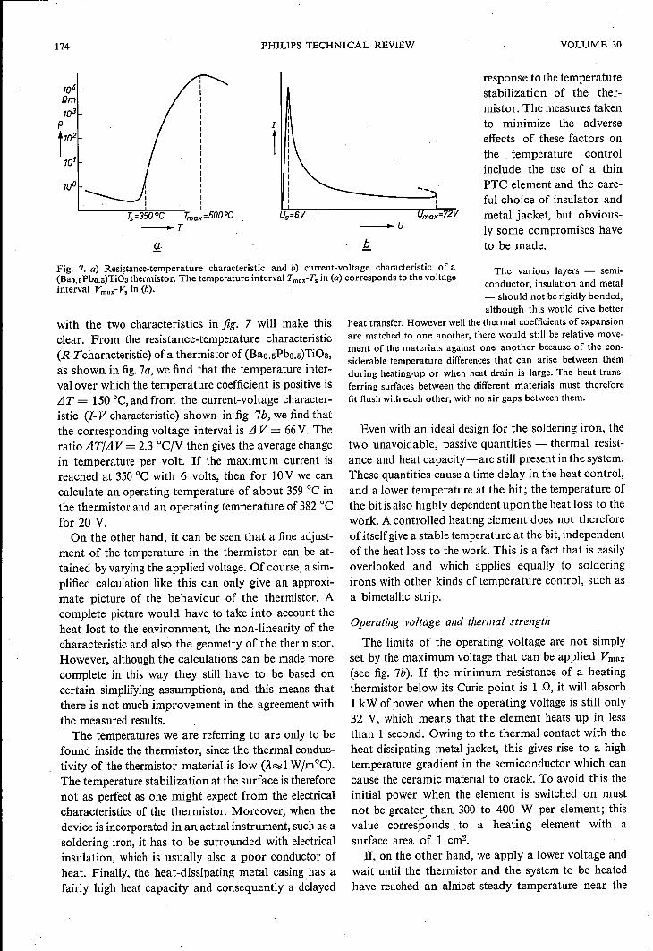
Fig. 7. a) Resistance-temperature characteristic and b) current-voltage characteristic of a(BaD.sPbo.s)TiOa thermistor. The temperature interval Tmu-Ts in (a) corresponds to the voltageinterval Vmnx- Vs in (b).
with the two characteristics in fig. 7 will make thisclear. From the resistance-temperature characteristic(R-Tcharacteristic) of a thermistor of (Bao.5Pbo.5)Ti03,as shown in fig.7a,we find that the temperature inter-val over which the temperature coefficient is positive isLIT = 150°C, and from the current-voltage character-istic (1- V characteristic) shown in fig. 7b, we find thatthe corresponding voltage interval is LIV = 66V. Theratio LlTjLl V = 2.3 °c/v then gives the average changein temperature per volt. If the maximum current isreached at 350°C with 6 volts, then for 10V we cancalculate an operating temperature of about 359°C inthe thermistor and an operating temperature of 382 °Cfor 20 V.
On the other hand, it can be seen that a fine adjust-ment of the temperature in the thermistor can be at-tained by varying the applied voltage. Of course, a sim-plified calculation like this can only give an approxi-mate picture of the behaviour of the thermistor. Acomplete picture would have to take into account theheat lost to the environment, the non-linearity of thecharacteristic and also the geometry of the thermistor.However, although the calculations can be made morecomplete in this way they still have to be based oncertain simplifying assumptions, and this means thatthere is not much improvement in the agreement withthe measured results.
The temperatures we are referring to are only to befound inside the thermistor, since the thermal conduc-tivity of the thermistor material is low (ÄR:ll Wjm°C).The temperature stabilization at the surface is thereforenot as perfect as one might expect from the electricalcharacteristics of the thermistor. Moreover, when thedevice is incorporated in an actual instrument, such as asoldering iron, it has to be surrounded with electricalinsulation, which is usually also a poor conductor ofheat. Finally, the heat-dissipating metal casing has afairly high heat capacity and consequently a delayed
The various layers - semi-conductor, insulation and metal- should not be rigidly bonded,although this would give better
heat transfer. However well the thermal coefficients of expansionare matched to one another, there would still be relative move-ment of the materials against one another because of the con-siderable temperature differences that can arise between themduring heating-up or when heat drain is large. The heat-trans-ferring surfaces between the different materials must thereforefit flush with each other, with no air gaps between them.
Even with an ideal design for the soldering iron, thetwo unavoidable, passive quantities - thermal resist-ance and heat capacity-are still present in the system.These quantities cause a time delay in the heat control,and a lower temperature at the bit; the temperature ofthe bitis also highly dependent upon the heat loss to thework. A controlled heating element does not thereforeof itself givea stable temperature at the bit, independentof the heat loss to the work. This is a fact that is easilyoverlooked and which applies equally to solderingirons with other kinds of temperature control, such asa bimetallic strip.
Operating voltage and thermal strength
The limits of the operating voltage are not simplyset by the maximum voltage that can be applied Vmax
(see fig. 7b). If the minimum resistance of a heatingthermistor below its Curie point is 1 n, it will absorb1 kW ofpower when the operating voltage is still only32 V, which means that the element heats up in lessthan 1 second. Owing to the thermal contact with theheat-dissipating metal jacket, this gives rise to a hightemperature gradient in the semiconductor which cancause the ceramic material to crack. To avoid this theinitial power when the element is switched on mustnot be greater than 300 to 400 W per element; this
'"value corresponds to a heating element with asurface area of 1 cm-,If, on the other hand, we apply a lower voltage and
wait until the thermistor and the system to be heatedhave reached an almost steady temperature near the
1969, No. 6/7 PTC HEATING ELEMENT 175
Curie point, we can then raise the voltage nearly to thelimit of the breakdown voltage, i.e. to about 70 volts inour case.It has also been found possible to make (Ba,Pb)Ti03
semiconductors that can be operated at the mainsvoltage. Laboratory models made from semiconduct-ing (Ban 5Pbo.5)Ti03 withstand fields up to 600 V/mmwithout breakdown. The R-T characteristic of thesethermistors shows a resistance increase above theCurie temperature of greater than 105. Unfortunatelycertain other features of these thermistors have madethem unsuitable so far for certain applications such assoldering irons. In particular, these thermistors usuallyhave too Iowa resistance below their Curie temperature:5 Q at 1 mm electrode spacing and 1 cm- cross-section.At an operating voltage of 220 V this would require aninitial power consumption of almost 10 kW, which isdefinitely too high for these semiconductors. On theother hand, if a high-resistance material with a e ofseveral tens of Dm is used, the negative temperaturecoefficient will have a marked effect between roomtempérature and the high Curie temperature. For ex-ample, if a (Ba,Pb)Ti03 thermistor has a resistance of300 Q just below a Curie ternperature of 340°C,its resistance at room température will be as much asten times higher, i.e. about 3000 D [3l. This behaviourincreases the heating-up time, so that this is no longerjust a few seconds.
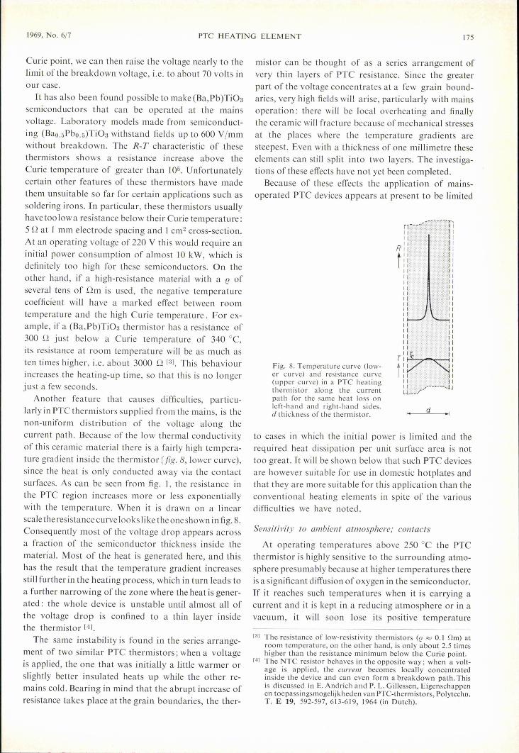
Another feature that causes difficulties, particu-larly in PTC thermistors supplied from the mains, is thenon-uniform distribution of the voltage along thecurrent path. Because of the low thermal conductivityof this ceramic material there is a fairly high tempera-ture gradient inside the thermistor (fig. 8, lower curve),since the heat is only conducted away via the contactsurfaces. As can be seen from fig. I, the resistance inthe PTC region increases more or less exponentiallywith the temperature. When it is drawn on a linearscale theresistancecurvelooks like the oneshown infig. 8.Consequently most of the voltage drop appears acrossa fraction of the semiconductor thickness inside thematerial. Most of the heat is generated here, and thishas the result that the ternperature gradient increasesstill further in the heating process, which in turn leads toa further narrowing of the zone where the heat is gener-ated: the whole device is unstable until almost all ofthe voltage drop is confined to a thin layer insidethe thermistor [4l.
The same instability is found in the series arrange-ment of two similar PTC thermistors; when a voltageis applied, the one that was initially a little warmer orslightly better insulated heats up while the other re-mains cold. Bearing in mind that the abrupt increase ofresistance takes place at the grain boundaries, the ther-
mistor can be thought of as a series arrangement ofvery thin layers of PTC resistance. Since the greaterpart of the voltage concentrates at a few grain bound-aries, very high fields will arise, particularly with mainsoperation: there will be local overheating and finallythe ceramic will fracture because of mechanical stressesat the places where the temperature gradients aresteepest. Even with a thickness of one millimetre theseelements can still split into two layers. The investiga-tions of these effects have not yet been completed.
Because of these effects the application of mains-operated PTC devices appears at present to be limited
Fig. 8. Temperature curve (low-er curve) and resistance curve(upper curve) in a PTC heatingthermistor along the currentpath for the sarne heat loss onleft-hand and right-hand sides.cl thickness of the thermistor. d
to cases in which the initial power is limited and therequired heat dissipation per unit surface area is nottoo great. It will be shown below that such PTC devicesare however suitable for use in domestic hotplates andthat they are more suitable for this application than theconventional heating elements in spite of the variousdifficulties we have noted.
Sensitivity to ambient atmosphere; contacts
At operating ternperatures above 250°C the PTCthermistor is highly sensitive to the surrounding atmo-sphere presumably because at higher temperatures thereis a significant diffusion of oxygen in the semiconductor.If it reaches such temperatures when it is carrying acurrent and it is kept in a reducing atmosphere or in avacuum, it will soon lose its positive temperature
[3] The resistance of low-resistivity thermistors (f! "'" 0.1 Om) atroom temperature, on the other hand, is only about 2.5 timeshigher than the resistance minimum below the Curie point.
[4] The NTC resistor behaves in the opposite way; when a volt-age is applied, the current becomes locally concentratedinside the device and can even form a breakdown path. Thisis discussed in E. Andrich and P. L. Gillessen, Eigenschappenen toepassingsmogelijkheden van PTC-thermistors, Polytechn,T. E 19, 592-597, 613-619, 1964 (in Dutch).
176 PHILlPS TECHNlCAL REVIEW VOLUME 30
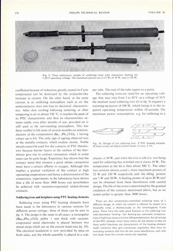
Fig. 9. Three laboratory models of soldering irons with thermistor heating for5-20 V operating voltage. The maximum powers are a) 23 W, b) 50 W, and c) 120 W.
coefficient because of reduction, greatly exceed its Curietemperature and be destroyed by the avalanche-likeincrease in current. On the other hand, at the samecurrent in an oxidizing atmosphere such as air thesemiconductor does not lose its electrical characteris-tics. After slow cooling following sintering, or aftertempering in air at about 550°C, it reaches the peak ofits PTC characteristic and then its characteristics re-main stable, even after months of use, provided air isstill used as the surrounding atmosphere. This hasbeen verified in life tests of several months on semicon-ductors of the composition (Bal-xPbx)Ti03, x havingvalues up to 0.6. The only sign of ageing observed wasat the metallic contacts, which oxidize slowly. Noblemetals cannot be used for the contacts of PTC thermis-tors because barrier layers at the surface of the ther-mistor give rise to contact resistances which in somecases can be quite large. Experience has shown that thecontact metal that ensures a good ohmic connectionmust have a certain affinity to oxygen. Although thisimplies a gradual oxidation of the contact at highoperating temperatures and hence a deterioration of theconnection, experiments in the laboratory have shownthat a life of more than 3000 hours can neverthelessbe achieved with vacuum-evaporated nickel-chromecontacts.
Soldering irons and hotplates using PTC heating elements
Soldering irons using PTC heating elements havebeen made in the laboratory in various versions fordifferent power ratings; three of them can be seen infig. 9. The design is the sarne in all cases; a rectangular(Bao.5Pbo.5)Ti03 pellet 1 mm thick with vacuum-evaporated metal electrodes is placed between twometal strips which act as the current leads (seefig. la).The electrical insulation is now provided by mica onboth sides, and the whole assembly is placed in a cop-
a
per tube. The end of the tube tapers to a point.The soldering irons are rated for an operating volt-
age that may vary from 5 to 20 V; at a voltage of 10 Vthe medium sized soldering iron (b in fig. 9) requires awarming-up power of 100 W, which brings it to the re-quired operating temperature within 10 seconds. Themaximum power consumption, e.g. for soldering to a
Fig. 10. Design of the soldering iron. E PTC heating element.M metal strips serving as current leads. G mica. L bit.
chassis, is 50 W, and when the iron is idle (i.e. not beingused for soldering but switched on) it draws 10W. Thetemperature at the bit is then about 300°C. The othertwo versions shown, a and c, draw maximum powers of23 Wand 120 W respectively and the idling powersare 7 Wand 20 W. A heating power of up to 30 W /cm2
can be obtained from these thermistors with carefuldesign. The life ofthe irons is determined by the gradualoxidation of the contacts mentioned above, but as wenoted earlier is greater than 3000 hours.
There are also temperature-controlled soldering irons of adifferent design, in which the control is effected by means of abimetallic strip, a thermocouple or the ferromagnetic Curiepoint. These have the same good features as the soldering ironwith thermistor heating: fast heating-up, automatic cernpensa-tion of high heat losses and a low idl ing temperature. A n advantageof the PTC element which these others do not possess is that allthese useful functions are characteristic of the heating elementitself; moreover they give continuous regulation, they have noswitching contacts and thus do not cause interference, and onlytwo leads from the current source are required.
1969, No. 6/7
A second application ofPTe heating elements, nowthe subject of experimentsin the laboratory, is a do-mestic hotplate fitted withmains-operated therrnis-tors. These, however, arestill in the laboratory stage.Fig. // shows a laboratorymodel and the two elementsthat heat the plate. Sincethese heati ngelements auto-matically limit their owntemperature, the hotplatecan be mass-prod uced in aninexpensive thermoplastichousing whose resistance todeformation can be guaran-teed only up to a specifiedtemperature. If a resistiveheating element without ex-ternal temperature controlis used, this is only pos-sible if the element IS
given a sufficiently highresistance, but it thentakes a relatively longtime for the plate to reachthe required temperature.Fig. /2 shows that the useof a thermistor permits fast-er heati ng up. Thermistorheating is here comparedwith the maxi mum permissi-ble ohmic heating of the
PTC HEATING ELEMENT 177
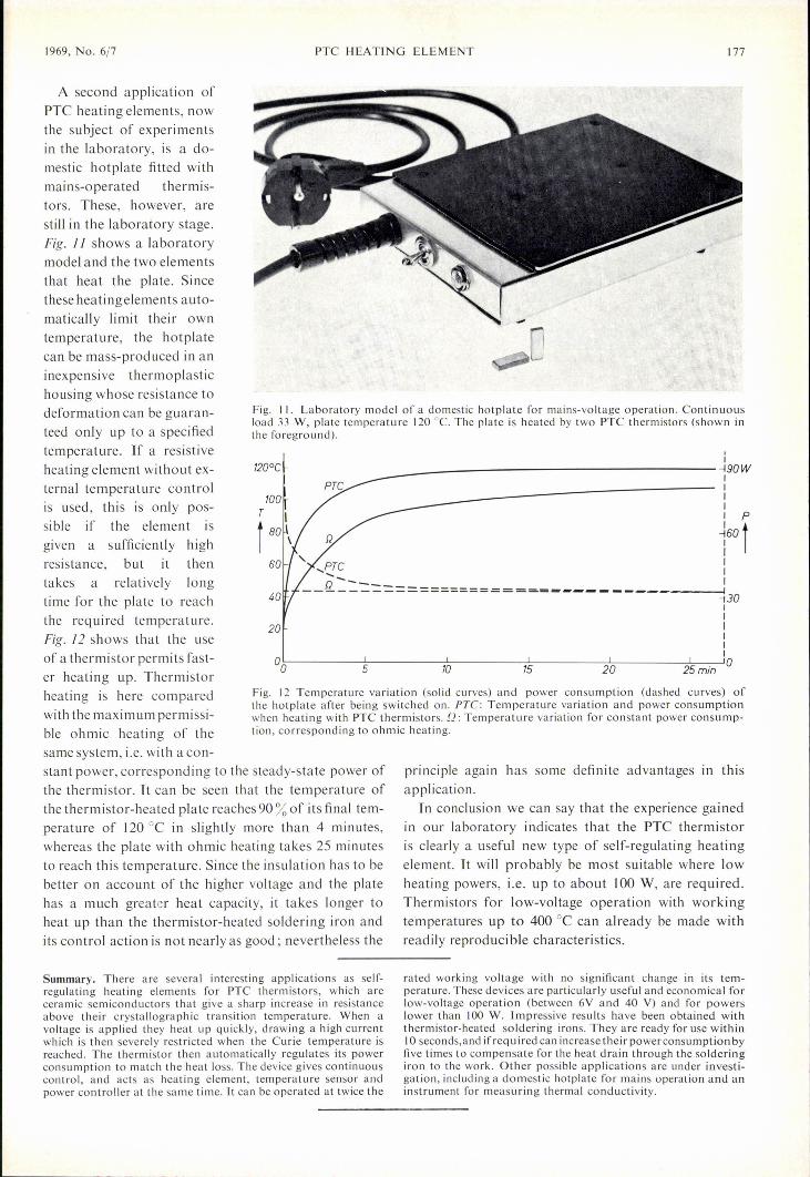
Fig. 11. Laboratory model of a domestic hotplate for mains-voltage operation. Continuousload 33 W, plate temperature 120°C. The plate is heated by two PTC thermistors (shown inthe foreground).
I
I___ ----------------------------------~90WIIIII P
160r,~c i
__ R:.:.::===============-= -II-130II1II
°0~--------~5~------~ILO--------~~~--------2LO---------2~5-m-i-n~10
20
Fig. 12 Ternper ature variation (solid curves) and power consumption (dashed curves) ofthe hotplate after being switched on. PTe: Temperature variation and power consumptionwhen heating with PTC thermistors. Q: Temperature variation for constant power consurnp-tion, corresponding to ohmic heating.
same system, i.e. with a con-stant power, cortesponding to the steady-state power ofthe thermistor. It can be seen that the tem perature ofthe thermistor-heated plate reaches 90 % of its final tem-perature of 120 oe in slightly more than 4 minutes,whereas the plate with ohmic heating takes 25 minutesto reach this temperature. Since the insulation has to bebetter on account of the higher voltage and the platehas a much greater heat capacity, it takes longer toheat up than the thermistor-heated soldering iron andits control action is not nearly as good; nevertheless the
principle again has some definite advantages in thisapplication.
In conclusion we can say that the experience gainedin our laboratory indicates that the PTe thermistoris clearly a useful new type of self-regulating heatingelement. It will probably be most suitable where Iowheating powers, i.e. up to about 100 W, are required.Thermistors for low-voltage operation with workingternperatures up to 400 oe can already be made withreadily reproduci bie characteristics.
Summary. There are several interesting applications as self-regulating heating elements for PTC thermistors, which areceramic semiconductors that give a sharp increase in resistanceabove their crystallographic transition temperature. When avoltage is applied they heat up quickly, drawing a high currentwhich is then severely restricted when the Curie temperature isreached. The thermistor then automatically regulates its powerconsumption to match the heat loss. The device gives continuouscontrol, and acts as heating element, temperature sensor andpower controller at the same time. Lt can be operated at twice the
rated working voltage with no significant change in its tem-perature. These devices are particularly useful and economical forlow-voltage operation (between 6V and 40 V) and for powerslower than 100 W. lmpressive results have been obtained withthermistor-heated soldering irons. They are ready for use within10 seconds,and ifrequired can increase their powerconsumption byfive times to cornpensate for the heat drain through the solderingiron la the work. Other possible applications are under investi-gation, including a domestic hotplate for mains operation and aninstrument for measuring thermal conductivity.