ptps panipat summer training report
TRANSCRIPT
Power Plant Familiarization
Project Report
Submitted in partial fulfillment of the requirements for the degree of
Bachelor of Technology (B.Tech)
Submitted to:
Mr. Amit DahiyaMechanical Engineering
Submitted by:
Anand KumarME/13/710
August 2016

Power Plant Familiarization
Project Report
Submitted in partial fulfillment of the requirements for the degree of
Bachelor of Technology (B.Tech)
Submitted to:
Mr. Amit DahiyaMechanical Engineering
Submitted by:
Anand KumarME/13/710
Under the Supervision of Er.A.K.Miglani
XEN/T.G. Mtc.-IV, Unit-6P.T.P.S Panipat
ACKNOWLEDGEMENT
This report gives the details of the project work done in six weeks Industrial training at
the end of 6th semester for partial fulfillment of the requirements for the degree of
Bachelor of Technology (B.Tech), under the Supervision of Er.A.K.Miglani (XEN/T.G.
Mtc.-IV, Unit-6), Er. Dhramvir (AEE/T.G. Mtc.-IV, Unit-6), Er. Krishan Kumar
(J.E/T.G. Mtc.-IV, Unit-6) and Mr. Amit Dilbagi (XEN/ Training Division).
I am highly obliged to department of training (P.T.P.S) for allowing me training at
TURBINE & GENERATOR MAINTANANC-IV and operators & technician of Turbine
& Generator section for the kind attention they have paid to me while instruction at the
plant site.
I have a profound sense of gratitude & appreciation to Electrical Engineer for directing
me for industrial training at Panipat Thermal power Station, Panipat.
_____________________ Signature of the Student
Name: _________________
Date: __________________

Table of Contents
1 INTRODUCTION.......................................................................................................8
1.1 THREE MAJOR INPUTS TO POWER STATION.............................................8
1.1.1 WATER.........................................................................................................8
1.1.2 FUEL OIL......................................................................................................9
1.1.3 COAL............................................................................................................9
1.2 FUNCTIONAL DESCRIPTION..........................................................................9
1.3 FAMILARIZATION WITH PLANT.................................................................10
1.3.1 BOILER.......................................................................................................10
1.3.2 TURBINE & GENERATOR (TG)..............................................................10
1.3.3 CONDENSER.............................................................................................11
1.3.4 COOLING TOWER....................................................................................11
1.3.5 ELECTROSTATIC PRECIPITATIOR.......................................................12
1.3.6 ASH HANDLING PLANT.........................................................................12
1.3.7 SWITCH YARD..........................................................................................12
1.3.8 ELECTRICITY FROM COAL...................................................................13
2 STEAM TURBINE...................................................................................................15
2.1 GENERAL DESCRIPTION...............................................................................15
2.1.1 GLAND SEAL & LEAK-OFF....................................................................15
2.1.2 ROTORS, BEARING AND TURNING GEAR.........................................15
2.1.3 TURNING GEAR.......................................................................................16
2.2 STEAM TURBINE THEORY............................................................................16
2.2.1 STEAM TURBINE AS A PRIME MOVER...............................................16
2.2.2 OPERATING PRINCIPLE.........................................................................17
2.2.3 STEAM CYCLE..........................................................................................17
2.3 DESIGN FEATURES.........................................................................................17
2.4 BARREL TYPE HIGH PRESSURE (HP) TURBINE.......................................18
2.5 INTERMEDIATE PRESSURE (IP) TURBINE.................................................19
2.6 LOW PRESSURE (LP) TURBINE....................................................................19
2.7 TURBINE SPECIFICATIONS...........................................................................21
3 DIFFERENT VALVES.............................................................................................23SBIT Page 4
3.1 COMBINED MAIN STOP VALVE AND CONTROL VALVE......................23
3.2 COMBINED REHEAT STOP VALVE AND CONTROL VALVE.................23
4 TURBINE OIL SYSTEM..........................................................................................23
4.1 OIL SUPPLY DURING NORMAL OPERATION............................................24
4.2 OIL SUPPLY DURING STARTUP AND SHUTDOWN.................................24
4.3 OIL SUPPLY DURING DISTURBANCES......................................................24
4.4 OIL STRAINER AND VAPOUR EXHAUSTER..............................................25
4.5 OIL LEVEL INDICATOR.................................................................................25
4.6 TYPE OF OIL PUMPS.......................................................................................25
4.6.1 MAIN OIL PUMP (MOP)...........................................................................25
4.6.2 AUXILIARY OIL PUMP (AOP)................................................................25
4.6.3 D.C. EMERGENCY OIL PUMP (EOP).....................................................25
4.6.4 JACKING OIL PUMP (JOP)......................................................................26
4.7 OTHER ACCESSORIES....................................................................................26
4.7.1 MAIN OIL TANK.......................................................................................26
4.7.2 OIL PURIFIER............................................................................................26
4.7.3 OIL FILTER................................................................................................26
5 COAL CIRCULATION............................................................................................27
5.1 COAL MILL.......................................................................................................27
5.2 CONSTRUCTION..............................................................................................27
5.3 WORKING.........................................................................................................28
5.4 CIRCULATORY SYSTEM...............................................................................28
5.5 DRAFT SYSTEM...............................................................................................29
6 WATER CIRCULATION SYSTEM........................................................................29
7 CONDENSER...........................................................................................................31
8 ELECTROSTATIC PRECIPITATOR......................................................................32
8.1 WORKING PRINCIPLE....................................................................................33
8.1.1 CORONA GENERATION..........................................................................33
8.1.2 PARTICLE CHARGING............................................................................33
8.1.3 PARTICLE COLLECTION........................................................................34
8.1.4 PARTICLE REMOVAL.............................................................................34
8.2 GENERAL DESCRIPTION...............................................................................34
SBIT Page 5
8.2.1 PRECIPITATOR CASING.........................................................................34
8.2.2 EMITTING AND COLLECTING SYSTEM.............................................34
8.2.3 HOPPERS....................................................................................................35
9 DUST COLLECTING HOPPER..............................................................................35
9.1 RAPPING MECHANISM..................................................................................35
9.2 GAS DISTRIBUTION SYSTEM.......................................................................35
9.2.1 ELECTRICAL SYSTEM............................................................................35
9.2.2 TECHNICAL SPECIFICATIONS OF ESP................................................36
9.2.3 ESP PROTECTIONS..................................................................................36
10 ASH HANDLING SYSTEM....................................................................................36
10.1 BOTTOM ASH SYSTEM..............................................................................36
10.2 FLY ASH SYSTEM........................................................................................37
10.3 ASH WATER SYSTEM.................................................................................37
10.4 ASH SLURRY SYSTEM...............................................................................37
11 REGENERATIVE SYSTEM....................................................................................38
12 HYDROGEN COOLING SYSTEM.........................................................................38
13 WATER CLARIFIER...............................................................................................39
13.1 D.M. PLANT...................................................................................................39
13.2 STEAM CONDITION....................................................................................40
14 CHIMNEY.................................................................................................................40
14.1 FLY ASH AND FLUE GAS CONDITIONING............................................40
15 FUNCTIONS OF VARIOUS PARTS OF THE CYCLE..........................................41
15.1 P.A. FANS.......................................................................................................41
15.2 AIR HEATER.................................................................................................41
15.3 SECONDARY AIR CYCLE...........................................................................41
15.4 F.D FANS........................................................................................................41
15.5 WIND BOX.....................................................................................................42
15.6 INDUCED DRAFT FANS (ID FANS)...........................................................42
16 CONCLUSION..........................................................................................................44
17 REFERENCES & BIBLIOGRAPHY.......................................................................45
18 CHECKLIST.............................................................................................................46
SBIT Page 6
List of Tables & Figures
Table No. 1: Different Stages of PTPS, Panipat..................................................................8
Fig. No. 1: Machinery Layout...........................................................................................10
Fig. No. 2: Arrangement of Cooling Tower......................................................................11
Fig. No. 3: Cooling Tower.................................................................................................12
Fig. No. 4: Turbine Tube...................................................................................................18
Table No. 2: HP Turbine Features.....................................................................................19
Table No. 3: IP Turbine Features......................................................................................19
Table No. 4: LP Turbine Features.....................................................................................20
Table No. 5 (a): Turbine Specification..............................................................................21
Table No. 5(b): Turbine Specification..............................................................................22
Fig. No. 5: Coal Handling Plant Coal Mill........................................................................28
Fig. No. 6: Condenser........................................................................................................31
Fig. No. 7: Condenser Tube...............................................................................................32
Table No. 6: Technical Specification of ESP....................................................................36
Fig. No. 8: FD Fan.............................................................................................................42
Fig. No. 9: Induced Draft Fan............................................................................................43
SBIT Page 7
1 INTRODUCTIONPanipat Thermal Power Station is situated at a distance of about 12 km. from Panipat. It is on Panipat-Jind Road near village Assandh. The power plant is one of the coal based power plants of HPGCL. The first four units were bifurcated from the total 8 units of the plant, so that to form Panipat Thermal Power Station I and II. Panipat Thermal Power Station I has an installed capacity of 447.80 MW. The First unit was commissioned in November 1979. In order to improve the performance of the all four units of the plant, the Renovation and Modernization has been started. This plant has been constructed in five stages as given below:
Name and Address
Stage Units Capacity
Panipat Thermal PowerStation,
Panipat.
Phone: 0180-2561573
Fax: 0180-2566806
Stage 1 Unit- 1 117.8 M.W.
Unit- 2 110 M.W.
Stage 2 Unit- 3 110 M.W.
Unit- 4 110 M.W.
Stage 3 Unit- 5 210 M.W.
Stage 4 Unit- 6 210 M.W.
Stage 5 Unit- 7 250 M.W.
Unit- 8 250 M.W.
Total Generation Capacity 1367.8 M.W.
Table No. 1: Different Stages of PTPS, Panipat
1.1 THREE MAJOR INPUTS TO POWER STATION
1.1.1 WATERWater has been taken from nearby Yamuna Canal. This water is lifted by raw water pumps and is sent to clarifier to remove turbidity of water. The clear water is sent to water treatment plant, cooling water system and service water system. The water is de-mineralized (DM) by water treatment plant. The DM water is stored in condensate storage tanks from where it is used in boiler.
SBIT Page 8
1.1.2 FUEL OILThe fuel oil used is of two types:
(a) Low sulphur high stock oil (LSHS)
(b) High speed diesel oil (HSD)
The high speed diesel oil reaches the power station through the lorry tankers. The oil is stored in large tanks for the future use in the boiler. Heavy oil is stored in storage tanks in oil storage yard and is conveyed to the front through a set of pumps and strainers. The whole length of piping from the boiler front in stream traced to maintain the temperature and hence its fluidity so that it can freely flow in the pipelines.
1.1.3 COALThe coal reaches the plant in the railways wagons. The unloading of coal is done mechanically by tilting the wagons by tippler. The coal is sent to the coal storage yard through the conveyor belts. The crushed coal from store is sent to the mill bunkers through conveyor belts. The air which takes away the coal dust passes upward into the classifier where the direction of flow is changed abruptly. This causes the coarse particle in the air coal stream to finer coal dust along with the primary air leaves the classifier onto the coal transport piping from where it goes to nozzle. Pulverized coal obtained from coal mill cannot be burnt directly.
1.2 FUNCTIONAL DESCRIPTIONThe Thermal Power Station burns fuel & uses the resultant to make the steam, which derive the turbo generator. The Fuel i.e. coal is burnt in pulverized from. The pressure energy of the steam produce is converted into mechanical energy with the help of turbine. The mechanical energy is fed to the generator where the magnet rotate inside a set of stator winding & thus electricity is produced in India 65% of total power is generated by thermal power stations. To understand the working of the Thermal Power Station plant, we can divide the whole process into following parts.
SBIT Page 9
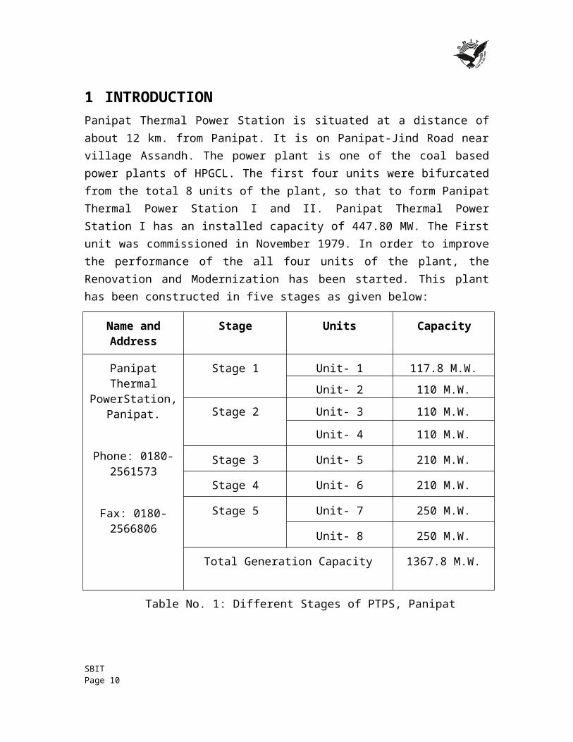
Fig. No. 1: Machinery Layout
1.3 FAMILARIZATION WITH PLANT
1.3.1 BOILERBoiler is a device used for producing steam. There are two types of boilers:
a) Fire tube boiler b) Water tube boiler
Here, boiler used is of water tube type. In the boiler, heat energy transfer takes place through tube walls and drum. The gases lose their heat to water in the boiler or superheated. The escape heat is used to heat the water through economizer. ID and FD fans are used to produce artificial draught. The fuel oil is used to ignite the boiler and pulverized coal is lifted from the coal mills by PA fans.
1.3.2 TURBINE & GENERATOR (TG)Turbine is form of heat engine in which available heat energy in the form of steam is converted into kinetic energy to rotate the turbine by steam expansion in suitable shaped nozzles In Thermal Power Station there are reaction turbines.
The turbine consists of three stages: high pressure, intermediate pressure and low pressure. Steam enters the turbine at 350oC with maximum allowable temperature of 545oC. Cold reheat steam goes to boiler, reheated at 540oC, then fed to medium pressure parts of the turbine. Then, after cooling it goes to the hot well. The shaft is coupled with generator.
SBIT Page 10
The generator converts the kinetic energy of the rotating shaft to electric energy. Field windings are excited by D.C. power using exciter. Shaft of generator rotates at 3000 rpm speed.
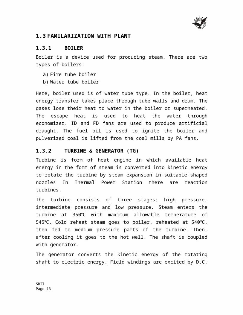
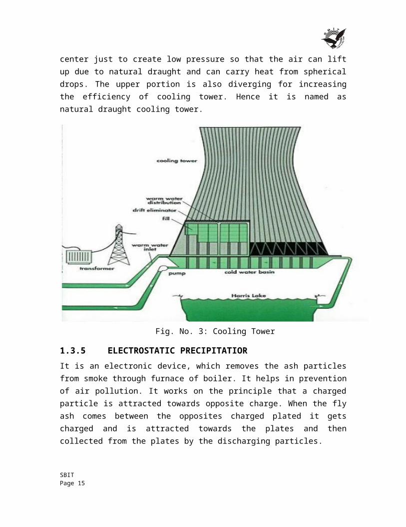
1.3.3 CONDENSERIn condenser, the water passes through various tunes and steam passes through a chamber containing a large number of water tubes (about 20000). The steam gets converted into water droplets, when steam comes in contact with water tubes. The condensate is used again in boiler as it is dematerialized water and 5-6 heats the water, which was in tubes, during the process of condensation. This water is sent to cooling tower.
Fig. No. 2: Arrangement of Cooling Tower
1.3.4 COOLING TOWERIt is a structure of height 110m designed to cool the water by natural draught. The cross sectional area is less at the center just to create low pressure so that the air can lift up due to natural draught and can carry heat from spherical drops. The upper portion is also diverging for increasing the efficiency of cooling tower. Hence it is named as natural draught cooling tower.
SBIT Page 11
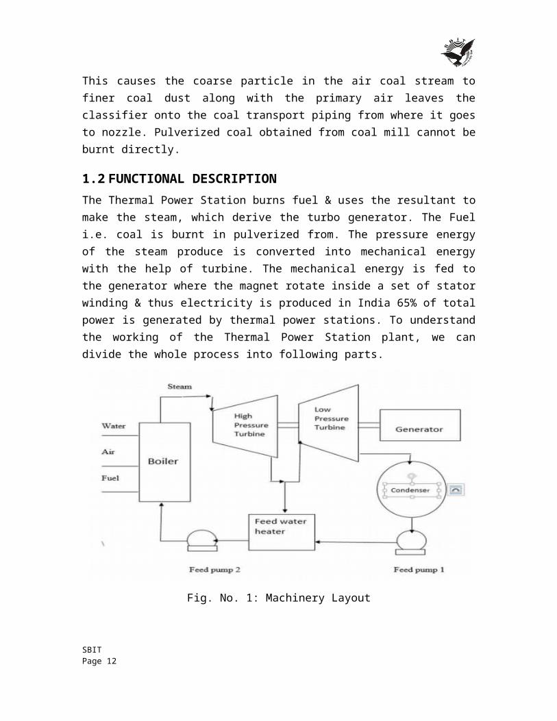
Fig. No. 3: Cooling Tower
1.3.5 ELECTROSTATIC PRECIPITATIORIt is an electronic device, which removes the ash particles from smoke through furnace of boiler. It helps in prevention of air pollution. It works on the principle that a charged particle is attracted towards opposite charge. When the fly ash comes between the opposites charged plated it gets charged and is attracted towards the plates and then collected from the plates by the discharging particles.
1.3.6 ASH HANDLING PLANTAsh is not discharged as such to pollute the land, air and water, but slurry of ash is made in ash handling plant and this slurry is dumped in the wasteland, kept for the purpose.
1.3.7 SWITCH YARDSwitchyard is the area, which feed the grid supply to the station transformer and feed the grid by the power generator by the unit. The power supply control is administrated here and the units consumed and supplies are recorded in the control room. The connections of 220KV BUS to the station transformer is done by using the isolated and gas filled circuit breakers.
SBIT Page 12
1.3.8 ELECTRICITY FROM COALElectric power generation takes place in the following steps:
1. Coal to steam 2. Steam to mechanical power 3. Switching and transmission
1.3.8.1 COAL TO STEAM The boiler burns pulverized coal at rates up to 200 tons per hour. From the coal store, fuel is carried on a conveyor belt and discharged by means of a coal tipper into the bunker. It then falls through a weighed into the coal pulverizing mill where it is ground to a powder as fine as flour. Air is drawn from the top of the boiler house by the forced draught fan and passed through the air pre-heaters to the hot air duct. From here some of the air passes directly to the burners and the remainder is taken through the primary air fan to the pulverizing mill, where it is mixed with the powdered coal, blowing it along pipes to the burners of the furnace. Here it mixes with the rest of the air and burns with great heat. The boiler consists of a large number of tubes and the heat produced raises the temperature of the water circulating in them to create steam, which passes to the steam drum at very high pressure. The steam is then heated further in the super heater and fed through outlet valve to the high pr. cylinder of the steam turbine.
When the steam has been through the first cylinder (high pr.) of the turbine, it is returned to the repeater of the boiler and reheated before being passed through the other cylinders (intermediate and low pr.) of the turbine. From the turbine the steam passes into a condenser to be turned back into water ‘condensate’. This is pumped through feed heaters where it may be heated to about 250oC to the economizer where the temperature is raised sufficiently for the condensate to be returned to the lower half of the steam drum of the boiler. The flue gases leaving the boiler are used to reheat the condensate in the economizer and then pass through the air pre-heaters to the electro-static precipitator. Finally they are drawn by the induced draught fan into the main flue and to the chimney.
1.3.8.2 STEAM TO MECHANICAL POWERFrom the boiler, a steam pipe conveys steam to the turbine through a stop valve and through control valves that automatically regulate the supply of steam of the turbine, Stop valve and control valves are located in a steam chest and a governor, driven from the main turbine shaft, operates the control valves to regulate the amount of steam used.
Steam from the control valves enters the high pr. cylinder of the turbine, where it passes through a ring of stationary blades fixed to the cylinder wall. These act as nozzles and direct the steam mounted on a disc secured to the turbine shaft.
SBIT Page 13
This second ring turns the shaft as a result of the force of the steam. The stationary and moving blades together constitute a ‘stage’ of the turbine and in practice many stages are necessary. The steam passes through each stage in turn until it reaches the end of the high pr. cylinder and in its passage some of its heat energy is charged into mechanical energy. The steam leaving the high pr. cylinder goes back to the boiler for reheating and is returned to the intermediate pr. cylinder. Here it passes through another series of stationary and moving blades.
Finally, the steam is taken to the low pr. cylinder each of which it enters at the center flowing outwards in opposite directions through the rows of turbine blades- an arrangement known as double flow-to the extremities of the cylinder. As the steam gives up its heat energy to drive the turbine, its temperature falls and it expands. The turbine shaft rotates at 3000 rpm at 50 Hz. The turbine shaft drives the generator to generate alternating current.
When as much energy as possible has been extracted from the steam it is exhausted directly to the condenser. This runs the length of the low pr. part of the turbine and may be beneath or on either side of it. From the condenser, the condensate is pumped through low pr. feed heaters by the extraction pump, after which its pr. is raised to boiler pr. by the boiler feed pump. It passed through further feed heaters to the economizer and the boiler for recon version into steam.
1.3.8.3 SWITCHING AND TRANSMISSIONThe electricity is usually produced in the stator windings of the large modern generators at about 25,000 volts and is fed through terminal connections to one side of a generator transformer that steps up the voltage 132000, 220000 or 400000 volts. From here conductors carry it to a series of three switches comprising an isolator, a circuit breaker and another isolator.
The circuit breaker, which is a heavy-duty switch capable of operating in a fraction of a second, is used to switch off the current flowing to the transmission lines. Once the current has been interrupted the isolators can be opened. These isolate the circuit breaker from all outside electrical sources.
From the circuit breaker the current is taken to the bus bars-conductors, which run the length of the switching compound and then to another circuit breaker with its associated isolates before feeding to the grid.
Three wires are used in a ‘three-phase’ system for large power transmission. The center of the power station is the control room. Here engineers monitor the output of electricity, supervising and controlling the operation of the generating plant and high voltage switch gear and directing power to the grid system as require
SBIT Page 14
2 STEAM TURBINEThe steam turbine is a prime mover that converts the stored mechanical energy in steam into rotational mechanical energy. A turbine pair consists of a ring of fixed blade and a ring of moving blades. The blades are so designed that the steam glides overt eh blade surface without striking it. As the steam floes over the covered surface of blade, it exerts a pressure on the blade along its whole length owing to its centrifugal force. The motive force on the blade will be the resultant of the centrifugal pressures on the blade length plus the effect of change of the steam as it flows over the blade.
2.1 GENERAL DESCRIPTION The turbine consists of three casings, high, medium and low pressure. HP part consists of two horizontally split casings-inner is placed inside, outer casing with scope for expansion in all direction. Fixed point of inner casing in the axial directions is between the nozzle chambers. Medium low pressure casing is split horizontally and comprise of 3 parts connected by vertical flanges. The outlet branches are connected rigidly with condenser which is supported on springs. In the middle casing, tube nests of 1st and 2nd
LP heaters are mounted. The casings are inter connected by guide keys and fixed points in the axial direction is at the central part of the LP casing. Total thermal expansion of the casings is indicated at front bearing pedestal and is approximately 25 mm when casings are fully stretched at rated steam parameters and at full load. The displacement of the bearing pedestal; between HP & MP parts is about 15mm. Relative expansion of rotors also are measured at 3 points.
2.1.1 GLAND SEAL & LEAK-OFFTurbine glands are sealed by steam at fixed pressure. Seal-steam, during starting and on low load period, is supplied from either cold R/H lines after N/R valves or from 11/6 ata header.
2.1.2 ROTORS, BEARING AND TURNING GEARAll the rotors including the rotor of the generator are mutually connected by means of rigid coupling. The critical speed of the turbine rotors is best noticed between 1900-2350 rpm. Double sided axial thrust bearing is located in between HP & MP casings. Two protections, one hydro-mechanical and one electro-magnetic are mounted near the axial bearing to trip the machine, in case the rotor movement crosses the prohibited limit on either side.
Differential expansions are measured at 3 points:-
on the front bearing pedestal
SBIT Page 15
on the pedestal between MP & HP parts and between LP & Generator to access relative expansion of stator and rotor
There are seven radial bearings on which rotor are supported. With proper expansion of all turbine parts, the load sharing is equal in all bearings. The bearings are placed in:
HP front standard between HP& MP at MP end both side of LP both side of generator
The journals are lifted by high pressure oil supplied by jacking oil pump at the time of putting machine on turning gear.
2.1.3 TURNING GEARThis equipment is located on the bearing pedestal between LP and generator and turns the rotor after shutdown or before start-up, at 62 RPM by an electric motor of 30 KW. The motor starting is possible only when lubricating oil pressure is available. The oil pressure required to put the swinging gear to engage with the coupling gear is 50 ata, supplied from jacking oil pump to a servomotor through an electro magnet.
2.2 STEAM TURBINE THEORYA turbine, being a form of engine, requires in order functioning a suitable working fluid, a source of high-grade energy. When the fluid flows through the turbine, apart of the energy content is continuously extracted and converted into useful mechanical work. Steam and gas turbines use heat energy while water turbines use pressure energy.
2.2.1 STEAM TURBINE AS A PRIME MOVERa) The steam turbine offers many advantages over other prime movers both
thermodynamically and mechanically. From a thermodynamic point of view the main advantage of the steam turbine over, say a reciprocating steam engine is that in the turbine the steam can be expanded down to a lower backpressure, thereby making available a greater heat drop. The same amount of heat drop in the case of a reciprocating engine would require very large cylinder, which would be impractical and uneconomic.
b) From a mechanical point of view the turbine is ideal because the propelling force is applied directly to the rotating element of the machine.
c) Another advantage of the turbine is the absence of internal lubrication. This means that the exhaust steam is not contaminated with oil vapor and can be condensed and fed back to the boiler.
SBIT Page 16
d) A final advantage of the steam turbine and a very important one is the fact that, size for size, a turbine can develop many times the power compared to a reciprocating engine whether steam or oil.
2.2.2 OPERATING PRINCIPLEa) A steam turbines two main parts are the cylinder and the rotor. The cylinder
containers fixed blades, vanes and nozzles that direct the steam into the moving blades carried by the rotor. The rotor is a rotating shaft that carries the moving blades.
b) In a multiple stage turbine, steam at a high pressure and high temperature enters the first row of fixed blades through an inlet valves. As the steam passes through the fixed blades, it expands and its velocity increases. The high velocity jet of steam the first set of moving blades. The kinetic energy of the steam changes into mechanical energy, causing the shaft to rotate. The steam then enters the next set of fixed blades and strikes the next row of moving blades.
c) As the steam flows through the turbine, its pressure and temperature decreases, while its volume increases. The decreases in the pressure and temperature occur as the steam transmits energy to the shaft and performs work. After passing through the last turbine stage, the steam exhausts into the condenser or process steam system.
d) The kinetic energy of the steam changes into mechanical energy through the impact or reaction of the steam against the blades. Many large turbines use both impulse and reaction blade. Blade rows require seals to prevent steam leakage where the pressure drops.
2.2.3 STEAM CYCLEThe Thermal (steam) Power Plant uses a dual phase cycle. It is closed to enable the working liquid (water) to be used again and again. The cycle used is ‘Rankine cycle’ modified to include super heating of steam, regenerative feed water heating and reheating of steam.
2.3 DESIGN FEATURES The turbine is of tandem compound design with separate High Pressure (HP), Intermediate Pressure (IP) and Low Pressure (LP) cylinders. The HP turbine is of Single Flow type while IP and LP turbines are of Double Flow type. The turbine is condensing type with single reheat.
It is basically engineered on reaction principle with throttle governing. The stages are arranged in HP, IP and LP turbines driving alternating current full capacity turbo generator.
SBIT Page 17
The readily designed HP, IP and LP turbines are combined and sized to required power output, steam parameters and cycle configuration to give most economical turbine set. The design and constructional features have proved their reliability in service and ensure trouble free operation over long operating periods and at the same time ensuring high thermal efficiencies.
Fig. No. 4: Turbine Tube
2.4 BARREL TYPE HIGH PRESSURE (HP) TURBINEThe outer casing of the HP turbine is of barrel type construction without any massive horizontal flange. This unique construction permits rapid startup from any thermal state and high rates of load changes of the turbo set. The steam and metal temperature matching requirements are also less stringent as there is no asymmetry of mass distribution in traverse or longitudinal planes.
The barrel type outer casing does not cause any problems during over hauls and capital maintenance as the assembly and disassembly of the turbine can be done in a relatively short time as compared to the conventional design. The HP turbine is of single flow type with 25 reaction stages.
SBIT Page 18
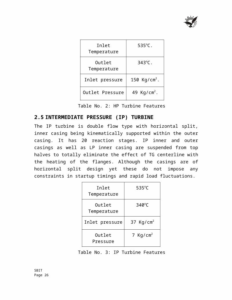
Inlet Temperature 535oC.
Outlet Temperature 343oC.
Inlet pressure 150 Kg/cm2.
Outlet Pressure 49 Kg/cm2.
Table No. 2: HP Turbine Features
2.5 INTERMEDIATE PRESSURE (IP) TURBINEThe IP turbine is double flow type with horizontal split, inner casing being kinematically supported within the outer casing. It has 20 reaction stages. IP inner and outer casings as well as LP inner casing are suspended from top halves to totally eliminate the effect of TG centerline with the heating of the flanges. Although the casings are of horizontal split design yet these do not impose any constraints in startup timings and rapid load fluctuations.
Inlet Temperature 535oC
Outlet Temperature 340oC
Inlet pressure 37 Kg/cm2
Outlet Pressure 7 Kg/cm2
Table No. 3: IP Turbine Features
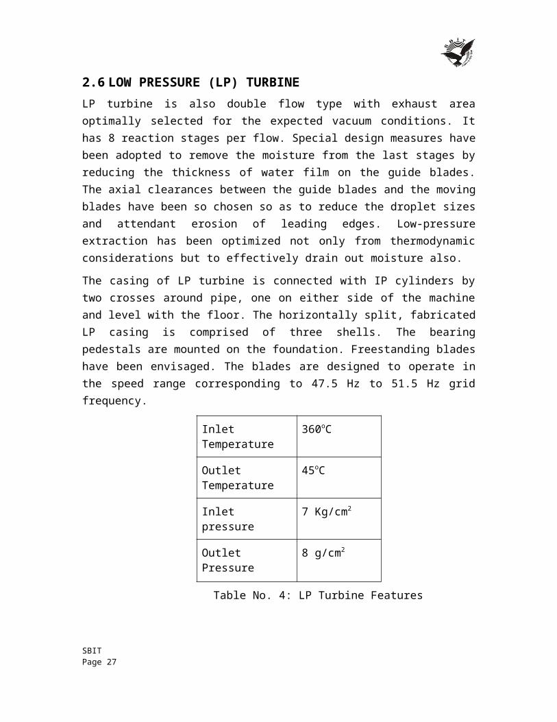
2.6 LOW PRESSURE (LP) TURBINELP turbine is also double flow type with exhaust area optimally selected for the expected vacuum conditions. It has 8 reaction stages per flow. Special design measures have been adopted to remove the moisture from the last stages by reducing the thickness of water film on the guide blades. The axial clearances between the guide blades and the moving blades have been so chosen so as to reduce the droplet sizes and attendant erosion of leading edges. Low-pressure extraction has been optimized not only from thermodynamic considerations but to effectively drain out moisture also.
The casing of LP turbine is connected with IP cylinders by two crosses around pipe, one on either side of the machine and level with the floor. The horizontally split, fabricated
SBIT Page 19
LP casing is comprised of three shells. The bearing pedestals are mounted on the foundation. Freestanding blades have been envisaged. The blades are designed to operate in the speed range corresponding to 47.5 Hz to 51.5 Hz grid frequency.
Inlet Temperature 360oC
Outlet Temperature 45oC
Inlet pressure 7 Kg/cm2
Outlet Pressure 8 g/cm2
Table No. 4: LP Turbine Features
SBIT Page 20
2.7 TURBINE SPECIFICATIONSMake BHEL
Rated Speed 3000 rpm
Rated Power 24000 Kg
Weight of HP Rotor 5500 Kg.
Weight of MP Rotor 11000 Kg.
Weight of LP Rotor 24000 Kg
Steam Pr. (rated)
Initial Steam 130 ata
Before MP casing 31063 ata
Steam Temp. (rated)
Initial Stem 535oC.
IP Cylinder Stop Valve Inlet 535oC.
HP Cylinder Exhaust 343oC.
LP Cylinder Exhaust 49oC.
Turning Gear Speed 62 rpm
Table No. 5 (a): Turbine Specification
SBIT Page 21
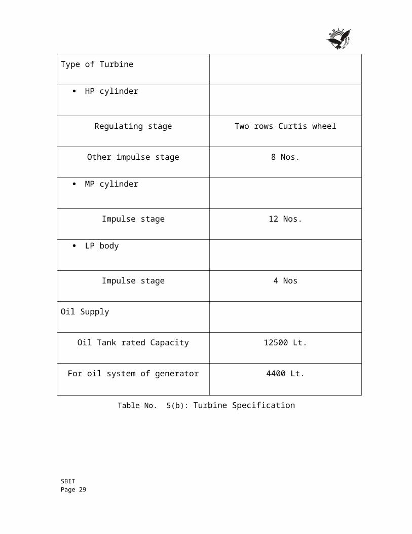
Type of Turbine
HP cylinder
Regulating stage Two rows Curtis wheel
Other impulse stage 8 Nos.
MP cylinder
Impulse stage 12 Nos.
LP body
Impulse stage 4 Nos
Oil Supply
Oil Tank rated Capacity 12500 Lt.
For oil system of generator 4400 Lt.
Table No. 5(b): Turbine Specification
SBIT Page 22
3 DIFFERENT VALVESHP turbine is fed from 2 combined emergency stop and control valves. Each combined valves consists of an emergency stop valve and control valve fitted in a common body with the spindles at right angles and in the same plane. The valves are placed on the mezzanine floor in front of the turbine. IP turbine is also fed from 2-combined reheat stop and control valves, which are mounted in the same way as the HP valves.
3.1 COMBINED MAIN STOP VALVE AND CONTROL VALVEThe main stop valves rapidly interrupt the supply of the steam to the turbine after being triggered by monitors should a dangerous conditions arises therefore they have been designed for high-speed closing and maximum reliability. The control valve on the other hand regulates the flow of steam to the turbine according to the prevailing load. One stop valve and one control valve a share a common body in which steam is perpendicular to each other and is placed in front of the turbine.
3.2 COMBINED REHEAT STOP VALVE AND CONTROL VALVEReheat stop valves are protective devices triggered by monitors in the event of dangerous conditions to interrupt the flow of steam to the reheat system. The reheat control valves are only operative in the lower range. Above this range, they remain fully open in order to avoid throttling losses.
4 TURBINE OIL SYSTEMMineral oil with additives (for increasing the resistance to corrosion and aging) is used as a fluid for actuating the governing system, lubrication of bearings and seal oil to generator seals. During normal operation the main oil pump supplies oil at pressure 8 bar approx. to the lubrication seal oil system and governing system. The oil system fulfills the following functions:
Lubricating and cooling the bearings. Driving the hydraulic turning gear during interruption operation, on startup and
shutdown. Jacking up the shaft at low speed.
Under normal conditions, the MOP (Main Oil Pump) situated in the front bearing pedestal and coupled directly to the turbine shaft, which draws oil from the main oil tank and supplies it to the pressure oil system. The suction of the main oil is aided by to injectors. The injector produces pressure at the suction connection to the MOP. This guarantees that the MOP takes over the supply of oil and cavitations that could occur due to greater suction heads and avoided. The amount of oil required is extracted SBIT Page 23

from the pressure oil circuit and is adjusted by throttles. The oil for turning gear is also extracted from the pressure oil system. Oil is admitted to the nozzles by opening the shut off valve. Cooled oil from the oil cooler is reduced to the lubricating oil pressure in the throttle. During turning gear operation and startup and run-down operation, one of the 3-Φ AOP (Auxiliary Oil Pump) supplies the pressure oil system and takes over the function of MOP when it is not in operation during turbine running too slow.
The submersible AOP is situated on the main oil tank and draws in oil directly. Check-Valves behind the AOP prevents oil from flowing back via pumps that are not in operation (i.e. MOP). When MOP and AOP fails, the lubrication oil supply is maintained by Emergency Oil Pump. The pump supplies oil directly to the lubrication oil line, by passing oil coolers and thus prevents damage to the bearings shells.
The AOP and EOP (Emergency Oil Pump) are automatically started control as soon as the pressure switch limit has been reach. The function of pressure switches arranged in the lubricating oil circuit is to operate the main trip valve when the lubricating oil pressure drops below a said value. The lubricating oil the bearing is returned to the main oil tank via a header. A loop in the return oil piping behind the seal oil reverse tank prevents H2 gas reaching the main oil tank when there is any disturbance. Oil for the Combined Journal and Thrust Bearing is passed through duplex oil filter, for cleaning during operation.
4.1 OIL SUPPLY DURING NORMAL OPERATIONDuring the normal operation the main oil pump supplies oil to the lubrication, seal oil system and governing system.
4.2 OIL SUPPLY DURING STARTUP AND SHUTDOWNDuring the startup and shutdown 2 auxiliary oil pumps meet the oil requirement of the TG set. They draw oil directly from the oil tank and discharged it into the pressure oil line and continue in operation till the main oil pump takes over the oil supply. A pressure switch in the pressure oil line gives an indication for switching off the auxiliary oil pump. During the shutdown another pressure switch automatically switches on the auxiliary oil pump.
4.3 OIL SUPPLY DURING DISTURBANCESWhen the pressure in the pressure oil line falls below a set point pressure switches automatically start the auxiliary oil pumps. The setting of pressure switches is arranged in stages so that on fall in oil pressure firstly one auxiliary oil pump is started and the second pump is stated only when the first pump fails to establish necessary oil pressure in the pressure oil line. In case main and auxiliary oil pumps cease to operate
SBIT Page 24

simultaneously a pressure switch in the lubrication oil line starts D.C. emergency oil pump.
4.4 OIL STRAINER AND VAPOUR EXHAUSTERThe basket type oil strainer is of stainless steel wire mesh of 0.25mm and is mounted in the tank. The whole tank is made airtight, this produces vacuum in the pump when MOP or AOP draws oil from main oil tank. Oil vapour exhauster produces a slight negative pressure in the tank, in the return drain line and in the spaces in the bearing pedestal so those oil vapours are drawn out.
4.5 OIL LEVEL INDICATORThe main oil tank has a direct reading fluid level indicator and a fluid limit switch. This permits signal to be transmitted to UCB when maximum and minimum levels have been reached. Extra tank volume is proved between the normal operating level and the tank cover to accept oil from the entire oil supply system when the turbine is shutdown.
4.6 TYPE OF OIL PUMPS
4.6.1 MAIN OIL PUMP (MOP)The MOP is situated in the front bearing pedestal and supplies the entire turbine with oil i.e. used for bearing lubrication, cooling the shaft journal and thrust bearing. It is driven by the turbine and develops the rated discharge pressure at 90-95% rated speed. The main pump is sized tot eh meet the normal requirements of Lubrication, Seal Oil and Governing System.
4.6.2 AUXILIARY OIL PUMP (AOP)It supplies the oil requirements of the turbo set during start-ups and shutdowns. The oil pump can either be switched on manually or automatically through pressure switches, which operate when the oil pressure drops to approximately 60% of the normal value.
The setting of the pressure switches is staggered so that one pump comes into operation before the other one with second one remaining in reserve. The pump continues to remain available for emergency service through the automatic control system. It is stopped after the turbo generator set has come to full speed and main oil pump has taken over.
4.6.3 D.C. EMERGENCY OIL PUMP (EOP)It is standby pump, which can be started manually or automatically through pressure switch when the tube oil pressure drops to 50% of the normal value. This happens only when main and auxiliary pumps fail to operate or there is a break down in the electricity
SBIT Page 25
supply system to the pumps. This pump should therefore be fed from station batteries. It has to be in operation and cater to the need of bearing lubrication and cooling of journals.
4.6.4 JACKING OIL PUMP (JOP)When the set is stationary, the shafts come into metallic contact with the bottom bearing lining. The normal bearing oil supply at low speeds is unable to penetrate to these surfaces and considerable force is required to initiate rotation of the shaft from rest. This is overcome by forcing high pressure oil through bottom bearing shell, thereby lifting the shaft in the bearings and allowing an oil film to form. Now shaft can be set in motion by application of considerably smaller force. This is a high pressure and low discharge pump.
4.7 OTHER ACCESSORIES
4.7.1 MAIN OIL TANKAll the oil pumps get supply from clean oil section of the tank. Bearing and other drains from turbo generator collect in the dirty section from where oil passes through one coarse and tow fine strainers. Strainers are removable from cleaning, during normal operation. Oil samples for testing, can be collected above mud collector.
4.7.2 OIL PURIFIERRemoves water and foreign particles from turbine oil. Takes supply of oil from bottom of mud collecting chamber.
4.7.3 OIL FILTERPart of the oil supplied by MOP is distributed through a filter to main relay, to an orifice for converting it to secondary oil and to speed sensing element.
SBIT Page 26
5 COAL CIRCULATION
5.1 COAL MILL Coal mills are mainly used to curse the coal. It cursed the coal in powder form. The powder form o coal is known as scream. In the Unit-5, 6 coal mills are present in the unit. In which 5 are working & I is standby.
5.2 CONSTRUCTIONa) It has three rollers, which are inclined at 120 degree angle to each other. b) A whirl shaft is mounted on a motor. It makes 1400 rpm. c) A-550 H.P. Motor used for rotation. It attached with shaft & it also attached with
a gear, which further transfer power to three roller and gives motion.d) Mainly three type bearing are used:
Radial Thrust Radial support
e) A pump is used for the lubrication oil, to transfer in the bearing & gear. f) A gland is provided to prevent the leakage of oil & a indicator which gives
indication of oil motion. g) An inlet pipe, coming from coal bunker is feed the coal in the mill.h) R.C. feeder provides B/W the inlet pipe & coal bunker.i) PA fan provide hot air from air pre-heater, for crushing purpose maintenance of
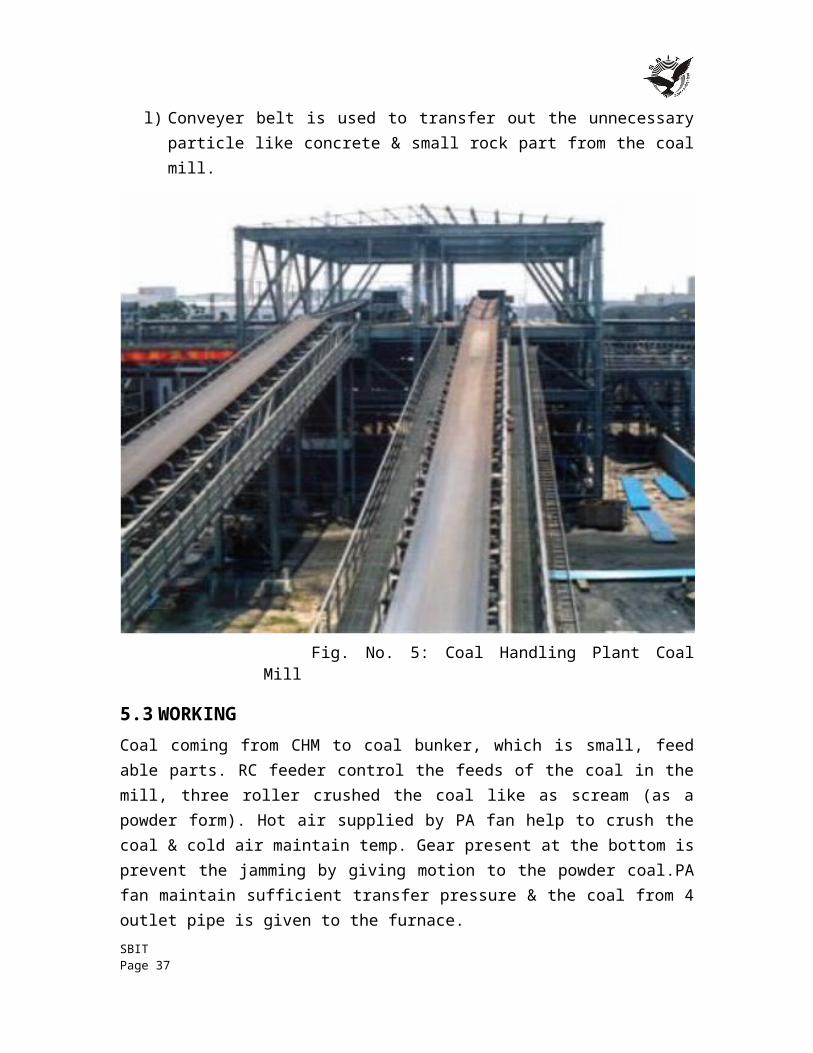
temperature.j) Also cold air is provided to maintain the temp.k) 4 pipe lines are used, which are used to transfer the scream coal to the furnace.l) Conveyer belt is used to transfer out the unnecessary particle like concrete &
small rock part from the coal mill.
SBIT Page 27
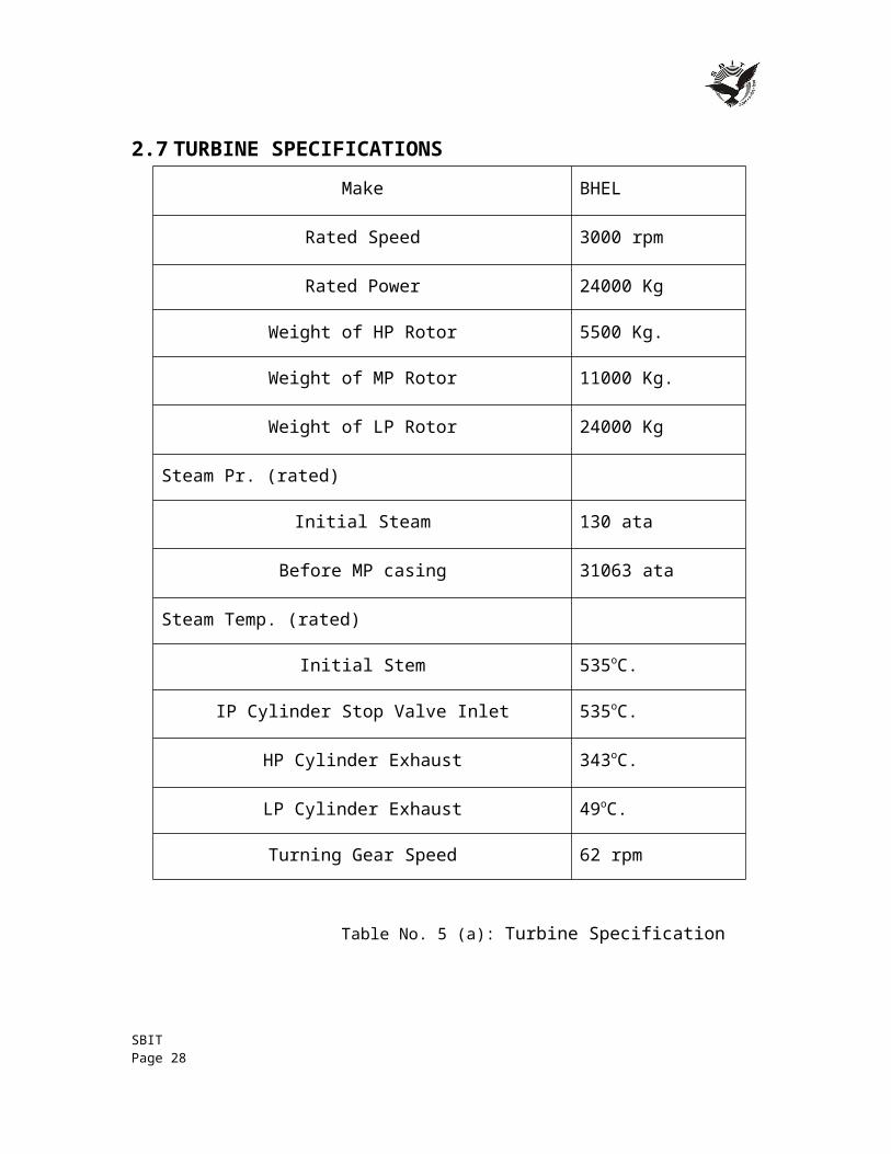
Fig. No. 5: Coal Handling Plant Coal Mill
5.3 WORKINGCoal coming from CHM to coal bunker, which is small, feed able parts. RC feeder control the feeds of the coal in the mill, three roller crushed the coal like as scream (as a powder form). Hot air supplied by PA fan help to crush the coal & cold air maintain temp. Gear present at the bottom is prevent the jamming by giving motion to the powder coal.PA fan maintain sufficient transfer pressure & the coal from 4 outlet pipe is given to the furnace.
5.4 CIRCULATORY SYSTEMCoal is transported from the coal mine with the help of train. Train wagons are emptied with the help of tippler and stored in coal yard. From here it goes to the coal crusher, where the big size coal is crushed and made into the required size. From coal crusher it goes to the coal bunker through conveyor belt and from coal bunker it move to R.C. feeder. R.C. feeder feeds coal to the coal mill, where the coal is ground into powder form. Air from primary air fan is introduced into the coal mill and coal powder mixed with it and goes to the classifier.
SBIT Page 28
The work of classifier is just to separate the un pulverized coal and feed it again to the coal mill. The pulverized coal mixed with air enters in the furnace at the corner through and forms a circle due to tangential fired. Here coal burns completely and releases heat and becomes in ash form. Ash in the furnace is taken away by ID fan through the Electrostatic precipitator. The purpose E.S.P. is to collect the ash. From the E.S.P. ash goes to the ash handling plant. The particles of ash which are not collected in the E.S.P. are goes to atmosphere through the chimney.
5.5 DRAFT SYSTEMThe force needed to draw air is called as draft. This force may be due to small pressure difference in the stream of flue gases or in the air which cause the flow to take place. In boiler it is necessary to supply sufficient quantity of air for proper combustion of the fuel and it is essential to force the fuel gases out of air for proper combustion of fuel and it is essential to force the fuel gases out of boiler. This is accomplished by suitable fans and this system is termed as mechanical draft as against natural draft.
In mechanical draft system, there are two type of application namely force draft & balance drafting. At P.T.P.S. balance draft system is used. Two fans are employed, one termed force draft other termed as induced draft fan. The F.D. fan is utilized to force atmospheric air into the furnace and then it is function of ID fan to such out the boiler flue gases through the economizer, air pre heater etc. & discharging it out through the stack. There two working together maintain a balance draft which is normally slightly negative pressure in the furnace.
6 WATER CIRCULATION SYSTEMIn this system the water is delivered to a system generation from heaters at a temperature well below the saturation value corresponding to that pressure. Entering the economizer, first it is heated, too much near the saturation temp. From economizer the water enters the drum and flows down through the drum comer and enters bottom of the riser tubes. In the riser tube, a part of water is converted to steam and the mixture flows back to the drum. In the drum, the steam is separated from water particles and fed to water value and, saturated steam is fed to radiant roof. From here saturated steam is sent to steam cooled water.
From steam cooled water valve, steam is given to LTSH. From LTSH steam is fed to platinum super heater and then goes to final super heater. In final super heater, temperature is up to 540oc and pressure is of 155 kg/cm2. At this temperature and pressure, steam enters in the H.P. turbine. After doing work steam goes to boiler re-heater at 38 kg/cm2 pressure and 380oc temp. In re-heater temperature raises 540oc and pressure falls to 36 kg/cm2.
SBIT Page 29

At this temperature and pressure steam enters into the I.P. turbine, here pressure falls to 11 kg/cm2 and 450oc and in this condition it enters in the L.P. turbine.
Turbine rotates at 3000 rpm and it is coupled to 6.6 KV generator which produces electricity. From L.P. turbine, steam passes to condenser where it is condensed to water that is collected in the hot well and it is extracted with the help of C.E.P. (condensate extraction pump) and fed to de-aerator through L.P. heater.
Thus the hydrostatic head available will not be able to overcome the frictional resistance for a flow corresponding to the minimum requirement of cooling of water wall tunes.
Therefore natural circulation to boiler is limited to pressure of 175 g/cm2 and in our case this pressure is about 138 kg/cm2 and hence natural circulation system is sufficient.
The process describes the effect produced by addition of alum to the colloidal suspended dispersion resulting in particle destabilization by a reduction force which lends to keep particle apart. Rapid mixing which is done in flash mixer in the clarifloculatior is done to obtain uniform dispersion. Second stage of formation of particle from destabilized colloidal fixed particle is termed as ‘flocculation’. Here coagulated particles grow in six by attaching to each other. At this stage particles are large enough to settle rapidly under the influence of gravity and may be removed. After this the water is passed through the anthracites pressure filter to remove the suspended impurities and there after sent to the activated carbon filter to de-chlorinate the filter water as the chlorine is harmful for the resins through which the water is to pass next. The D.M. water is obtained by ion exchange process. The filtered water is first passed through cation exchanger process where the cations of dissolved impurities are removed. Then it is passed to the de-gassifier tower where most of CO2 is removed.
Thus the pure D.M. water is obtained which is stored in the storage tanks for make-up. During the process of D.M. cation and anions resins get discharge and have to be reactivated with the help of HCL and caustic soda D.M. of water is done to prevent the scale sludge formation problem in the boiler drum which restricts the transfer of head of water.
SBIT Page 30
7 CONDENSERThe steam after working in the turbine is condensed in condenser in each unit installed below the LP exhaust. The condenser is of surface type made of fabricated construction in single shell. The tube is of divided type double pass arrangement, having two independent cooling water inlet, outlet and reserve and water boxes. The condenser is provided with integral air-cooling zone at the centre from where air and non-condensable gases are continuously drawn out with the help of mechanical vacuum pump.
The condensate is collected at the bottom portion of the condenser called the hot well from where it is pumped up to the de-aerator by the condensate pumps through the different heating stages. The function of the condenser is to condense the out coming steam from LP turbine. In the condenser cooling water flows through the tubes and exhaust steam from the turbine outside the pipes.
Area of condenser 9655m2.
Cooling water flow rate 2400m3/Hr.
Fig. No. 6: Condenser
SBIT Page 31
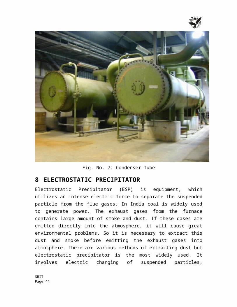
Fig. No. 7: Condenser Tube
8 ELECTROSTATIC PRECIPITATORElectrostatic Precipitator (ESP) is equipment, which utilizes an intense electric force to separate the suspended particle from the flue gases. In India coal is widely used to generate power. The exhaust gases from the furnace contains large amount of smoke and dust. If these gases are emitted directly into the atmosphere, it will cause great environmental problems. So it is necessary to extract this dust and smoke before emitting the exhaust gases into atmosphere. There are various methods of extracting dust but electrostatic precipitator is the most widely used. It involves electric changing of suspended particles, collection of charge particles and removal of charged particles from collecting electrodes. Its various other advantages are as follows:
a) It has high efficiency i.e. about 99% b) Ability to treat large volume of gases at high temperature. c) Ability to cope with the corrosive atmosphere. d) It offers low resistance to the flow of gases. e) It requires less maintenance.
SBIT Page 32
8.1 WORKING PRINCIPLEThe electrostatic precipitator utilizes electrostatic forces to separate dust particles from the gases to be cleaned. The gas is passed through a chamber, which contains steel plates (vertical) curtains. These steel curtains divide the chamber into number of parallel paths. The framework is held in place by four insulators, which insulate it electrically from all parts, which are grounded. A high voltage direct current is connected between the framework and the ground, thereby creating strong electric field between the wires in the framework curtains.
Strong electric field develops near the surface of wire creates Corona Discharge along the wire. Thus ionized gas produces +ve and –ve ions.
In the chamber plates are positively charged whereas the wire is negatively charged. Positive ions are attracted towards the wire whereas the negative ions are attracted towards the plates. On their way towards the curtains negative ions strike the dust particles and make them negatively charged. Thus ash is collected on the steel curtain. The whole process is divided into the following parts:
a) Corona Generation. b) Particle Charging. c) Particle Collection. d) Particle Removal.
8.1.1 CORONA GENERATIONCorona is a gas discharge phenomenon associated with the ionization of gas molecules by electron collision in regions of high electric filed strength. This process requires non-uniform electric filed, which is obtained by the use of a small diameter wire as one electrode and a plate or cylinder as the other electrode. The corona process is initiated by the presence of electron in strong electric field near the wire. In this region of corona discharge, there are free electrons and positive ions. Both positive and negative coronas are used in industrial gas cleaning.
8.1.2 PARTICLE CHARGINGThere are two physical mechanisms by which gas ions impact charge to dust particles in the ESP. Particles in an electric fields causes localized distortion in an electric filed so that electric field lines intersect with the particles. The ions present in the filed tend to travel in the direction of maximum voltage gradient, which is along electric field lines. Thus ions will be intercepted by the dust particles resulting in a net charge flow to the dust particles.
SBIT Page 33
8.1.3 PARTICLE COLLECTIONThe forces acting on the charged particles are Gravitational, Inertial, Electrostatic and Aerodynamically. The flow of gas stream is turbulent flow because it causes the particles to flow in random path through ESP. Particles will be collected at boundary layers of collector pates. But if flow is laminar, charge will act on particles in the direction of collecting electrode. This force is opposite to viscous drag force and thus in the short time, particle would achieve Terminal (Migration) velocity at which electrical and viscous forces are equal. Thus the flow of the charged particles is decided by the vector sum of these forces i.e. Turbulent.
8.1.4 PARTICLE REMOVALIn dry removal of dust collected on plates, Rapping Mechanism is used. It consists of a geared motor, which moves a long shaft placed near the support collector electrode and is provided with cylindrical hammer. On rotating of shaft these hammers strikes the supports causes plates to vibrates and dust is removed from plates. Removed dust is collected in the Hoppers below the precipitator. So there is a chance of ash deposit at the exit of the hopper thus causing problem of removing the ash. To avoid this, heaters are provided which increase the temperature at the exit point of the hopper thus avoiding any undue accumulation of ash at starting. In order method, the water is allowed to flow down the collector electrode and hence dust is collected in hoppers below.
8.2 GENERAL DESCRIPTIONThe whole Electrostatic Precipitator is divided into following two parts:
Mechanical System.
Electrical System.
Mechanical system: Mechanical system comprises of Precipitator Casing, Hopper, Collecting and emitting system, and Rapping mechanism, Gas Distribution System.
8.2.1 PRECIPITATOR CASINGPrecipitator Casing is made of 6mm mild steel plate with required stiffness. The precipitator casing is all welded construction comprising of pre-fabricated walls and proof-panels. The roof carries the precipitator internals, insulator housing, transformer etc. Both emitting and collecting systems are hung from the top of the casing.
8.2.2 EMITTING AND COLLECTING SYSTEMEmitting System is the most essential part of ESP. Emitting system consists of rigid emitting frame suspended from four points on the top and emitting electrodes in the form of open spiral. The four suspension points are supported on support insulators to give electrical insulation to the emitting frame.
SBIT Page 34
The frame is designed to take up the retention forces of the emitting electrode. The emitting electrodes consist of hard drawn spiral wires and are fastened with hooks to the discharge frame. Collecting system mainly consists of collecting suspension frame, collecting electrodes and shock bars. Collecting electrodes are made of 1.6mm thick Mild Steel sheets formed in ‘G’ Profile of 400mm width. Hook and guide are welded on one end and shock iron on the other end on a fixture.
8.2.3 HOPPERSHoppers are seized to hold the ash for 8-hour collection and are provided under the casing of ESP. It is of Pyramidal Shape and is 56 in number. It is preferred to evacuate the hoppers at the earliest as long storage of dust in hopper leads to clogging of hopper. Also at the bottom of hopper electrical heating is provided to avoid any condensation, which could also lead to clogging of hopper. Baffle plates are provided in each hopper to avoid gas leakage.
9 DUST COLLECTING HOPPER
9.1 RAPPING MECHANISMDuring electrostatic precipitation a fraction of the dust will be collected on the discharge electrodes and the corona will be suppressed as the dust layer grows. So, rapping is done in order to remove this dust by hammering the electrodes. As the shaft rotates the hammer tumbles on to the shock bar that transmits the blow to the electrode. The whole rapping mechanism is mounted on a single shaft, which is coupled with the gear drive motor. The rapping system avoids the collection of ash on the collecting electrode
Specification: Voltage and Current 415V and 5Amp
Power and Speed 3.7KW and 710 rpm
9.2 GAS DISTRIBUTION SYSTEMThe good performance of the ESP depends on even distribution of gas over entire cross section of field. Gas Distribution System distributes the gas evenly in ESP and maintains its efficiency.
9.2.1 ELECTRICAL SYSTEMIn precipitator we require high voltage dc supply to generate sufficient electric field. Electrical system comprises of High Voltage transformer Rectifier (HVR) unit with Electronic Controller (EC), Auxiliary control panel, Safety Interlocks and Field equipments.
SBIT Page 35

9.2.2 TECHNICAL SPECIFICATIONS OF ESPInput to the thyristor controller 415 V (AC)Output of T/F or input to ESP 70 KV (DC)No. of ESP per unit 2No. of fields in series of gas path 7Time of the flue gas pass through ESP 32.31 secNo. of electrode per boiler 3780No. of hoppers per unit 56No. of rapping motors for collecting electrodes 14 per unitNormal height of collecting electrodes 12.5 m
Table No. 6: Technical Specification of ESP
9.2.3 ESP PROTECTIONS
Short Circuit Protection: By under voltage relay 10-50% of primary volts with time delay from 10 sec to 80 sec can be adjusted.
Over-Load Protection: By thermal overload relay on primary side.
10 ASH HANDLING SYSTEMIt is very import to control the ash coming from the furnace.
a) WET ASH HANDLING SYSTEM
b) DRY ASH HANDLING SYSTEM
A pipe line from ESP which contains the ash in divided in two parts. Use of Dry ash Evacuation instead of WET deashing System: Dry deashing system consumers less power & also minimizes waste reduction. The dry ash is directly transferred by vacuum system at desired place in plant it transfers to nearest cement factory. It is act as a good source of income for the plant.
The wet ash is transferred to the wet ash handling, in this vacuum created by water flow. Ash mix with the water and transferred to the ash pump from there it is drain out from the plant in to the lake. From here it is given to the raw water storage. The ASH produced in the boiler is transported to ASH dump area by means of sluicing type hydraulic ASH handling system. This consists of bottom ash system. Ash water system, fly ash system, ash slurry system which are explained as follows:
10.1BOTTOM ASH SYSTEMIn the bottom ash system, the ash slag discharge from furnace bottom is collected into water impounded scraper through installed bellows water ash system. The ash is continuously transported by means of scrapper chain conveyor on the respective clinker grinders which reduce the lump sixes to the required fineness. The crushed ash from the SBIT Page 36
clinker grinders falls in to the ash slurry further transported to ash slurry sump added by ash sluice channel. If the clinker grinder is not in operation, bottom ash can be discharged directly into the sluice channel through the bifurcating chute by passing the grinder. The position of the top gate in the bifurcating chute is to be manually changed.
10.2FLY ASH SYSTEMThe flushing hoppers are provided under EP hopper (40nos), Economizer hoppers (4nos), air pre heater (4nos) & stack hoppers (2nos). The fly ash collected in these hoppers drop continuously to flushing apparatus where fly ash get mixed with flushing water & the resultant slurry drops into the ash sluice channel. Low-pressure water is applied through the nozzle directing tangentially to the section of pipe, to create turbulence & proper mixing of ash, with water.
10.3ASH WATER SYSTEMHigh pressure water required for B.A. hoppers quenching nozzles, window spraying, clicking grinder sealing bars, cleaning nozzles, B.A. hoppers seal through flushing, economizer hoppers, flushing nozzles is tapped from the high pressure water ring main provided in the plant area.
10.4ASH SLURRY SYSTEMBottom Ash and Fly Ash slurry of the stream is sluiced up to ash slurry along the channel with the aid of high-pressure water get located at suitable interval along the channel. Slurry pump suction line consisting of reducing elbow with drain value, reducer and butterfly value and portion of slurry pump, delivery line consisting of butterfly value, pipe & fittings as also been provide.
Now the oil is first atomized in the oil guns under the pressure of steam through nozzles and after atomization, the oil is sprayed at every corner of the furnace for initial ignition. After this coal received from the mill in pulverized form is burnt in the furnace. Combustion air is supplied through the forced air fans and primary air fans. The coal after the combustion gives out the energy, which is used to heat up water in tubes and convert this water into steam. The flue gases formed are taken through chimneys with the help of induced fans.
SBIT Page 37

11 REGENERATIVE SYSTEMThe condensate and feed water are heated in 8 stages by the non-regulated extractions from the turbine, comprising of 5 low pressure heaters, a de-aerator and two high pressure heaters. In addition to this, the entire condensate flows to de-aerator, through steam jet air ejector, chimney steam condenser and gland steam condenser.
The first and second stage of regenerative heating is done by two, double low pressure heaters which are mounted directly in the low pressure casing of the turbine. In between the 2nd and 3rd stages of heating, the chimney steam and gland steam condensers are located.
3rd, 4th and 5th low pressure heaters form the individual stages of heating. The de-aerator forms the next stage of heating, heated by the steam from Extraction-VI. The condensate cycle is protected from any abnormal rise of pressure by relief safety valves.
The high pressure heaters are located in the feed water cycle between the feed water pump and the boiler and heated by steam from the 7th and 8th extractions. The 8th
extraction steam is taken from the cold reheat line.
12 HYDROGEN COOLING SYSTEMHydrogen gas is one of the best cooling media chosen for turbo-Alternator Cooling. Its supremacy over other cooling medium and final selection for use is due to:
(a) Higher heat transfer co-efficient.(b) Thermal conductivity 7.3 times better than air. (c) Ability to transfer heat through forced convection 50% better than air. (d) Permitting higher current densities for the same temperature rise and with more
efficient cooling. This allows higher outputs. (e) Elimination of fire risk since hydrogen will not support combustion. (f) Corona discharge is not harmful to insulation since oxidation is not possible. (g) Smooth operation of machine in view of virtual elimination of windage noise and
the use of heavy gas tight enclosure. (h) Its density begin approximately 1/14th that of air at a given temperature and
pressure due to which windage loss is 1/10th in comparison of air as cooling medium.
(i) Reduced machine maintenance because of gas tight enclosure and hence a dirt proof casing.
SBIT Page 38
13 WATER CLARIFIERIt received impure water from raw water storage. In raw water storage big suspended particle settle down. In water clarifier the purification of raw water held in two processes.
I. Coagulation II. Chlorination
In coagulation, Potash alum is added in the water. In this process the file suspended & colloidal particles are removed from water.
In chlorination, chlorine gas is added to the water, which have disinfectant action & it kills the harmful bacteria, germs & destroyed the pathogenic micro organism. Excess of chlorine in water will effect to the taste of water.
13.1D.M. PLANT In the DM Plant the water is D-mineralized. The water is used for steam generation is must be free from colloidal & dissolved impurities. All the colloidal impurities are removed in the Water Clarifier. Then it supplied to the DM Plant.
Here the water contains dissolved impurities, which are mainly the salt of Ca, Na & Mg. It mainly sulphates, chloride, CaSO4, NaCl, CaCl2 etc
In the DM Water Ist sent to the Sand filter & rest of the colloidal impurities are removed. Sand filter AC filter Cation tank Gas tower Anion tank
Now the water goes to the Activated Carbon filter. Here the excess of the chlorine is decomposed.
Then water supplied in the cation tank & in this cation (Ca++, Na+ , Mg++) are removed & water with anion allow to pass ahead. R-H+ + NaCl R Na + H Cl
HCl is added time to time to improve the conc. of the cation tank. The process is known as the Regeneration.
Then it allows passing from the gas tower which removed the Co2 which produced during the purification process.
Then it pass from the anion tank & all the anion Cl -, So4- - are removed out. Also regeneration are done by adding any base solution, like NaOH etc.
SBIT Page 39
At last it passed in the mixed bed all the minerals present in the water removed & the water is completely free from minerals.
13.2STEAM CONDITIONTri sodium phosphate & ammonia is added to maintain the pH of the water at specified value. Also another chemical N2H4 to remove the dissolved oxygen present in the water.
a) Air Pre-heater: Regenerative air pre-heaters cause temperature and SO3
stratification in the downstream gas flow. This problem is more severe in closely coupled systems, where the precipitator is located closed to the air pre-heater. Depending upon site-specific conditions, flow mixing devices may be installed in the ductwork to the precipitator, or flue gas conditioning systems may be used to equalize the gas flow characteristics.
b) Coal Burner: The operation of coal burners, together with the setting of the coal mills and their classifiers, affects the percentage of unburned carbon (LOI or UBC) in the fly ash. The use of Lo-NOx burners increases this percentage, and caused re-entertainment and increased sparking in the precipitator. Further, the UBC tends to absorb SO3, which in turn increases the fly ash resistivity. Over-fire air optimization or coal re-burn systems may reduce UBC in the fly ash.
14 CHIMNEYThe gases produced due to burning of coal are comes out from chimney. The height of chimney is designed with respect to the boiler layout. The temperature is also maintained in the chimney. It is not more than 120 c. If it more than 120 c, then boiler will be corrupt.
14.1FLY ASH AND FLUE GAS CONDITIONING Flur gas and fly ash characteristics at the inlet define precipitator operation. The combination of flue gas analysis, flue gas temperature and fly ash chemistry provides the base for fly ash resistivity involves both surface and volume resistivity. As gas temperature increases, surface conductivity decreases and volume resistivity increases.
In lower gas temperature ranges, surface conductivity predominates. The current passing through the precipitated fly ash layer is conducted in a film of weak sulfuric acid on the surface of the particles. Formation of the acid film (from SO3 & HO) is influenced by the surface chemistry of the fly ash particles.
In higher gas temperature ranges, volume conductivity predominates. Current conduction through the bodies (volume) of the precipitated fly ash particles is governed by the total chemistry of the particles. Fly ash resistivity can be modified (generally with the intent to reduce it) by injecting one or more of the following upstream of the precipitator.
SBIT Page 40
Sulfur trioxide (SO3) Ammonia (NH3) Water
15 FUNCTIONS OF VARIOUS PARTS OF THE CYCLE
15.1P.A. FANSThese fans are used to supply the hot air in order to dry powdered coal. To transport pulverized coal to the furnace the speed of PA fans 1400 rpm and they supply 83800 m3 per hour. These are installed either side of boiler.
15.2AIR HEATERIt is an essential part of a thermal power plant as hot air is necessary for rapid and efficient combustion in the furnace and also for drying coal in the milling plant. At PTPS tabular type air heater are being used it consists of large number of steel type welded to the tube plates at the end. Gas is allowed to flow through the tubes and cold air passes around these tubes and gets heated up. These air heaters provide primary as well as secondary air.
15.3SECONDARY AIR CYCLE In this cycle FD FANS suck air from the atmosphere and supply it to the wind box of the furnace through air heater and regulating dampers. Then it moves to the furnace as per requirements.
15.4F.D FANS These are used to take air from the atmosphere at ambient temperature to supply it
to the furnace for combustion purpose. Speed is about 990 rpm and it handles 203760 m3 of air per hour. These are installed either side of boiler.
SBIT Page 41
Fig. No. 8: FD Fan
15.5WIND BOX This acts as distributing media for supplying secondary and excess air to combustion chamber. These are generally located at right and left side of the furnace while facing the chimney.
15.6 INDUCED DRAFT FANS (ID FANS) These are used to suck the flues gases from the furnace and through it into the
stack so as to dispose them off into the atmosphere. It handles flash laden gases at a temp. Of 125 to 200degrees Its speed is around 970 rpm and it handles 453600 m3 of air per hour These are installed at the outlet of electrostatic precipitator.
SBIT Page 42
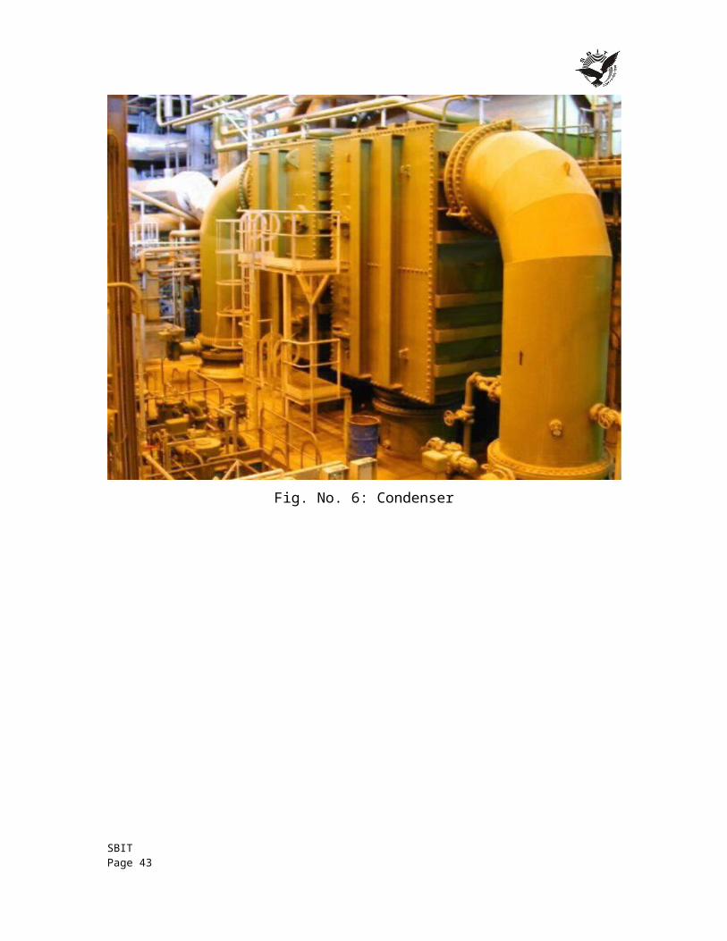
Fig. No. 9: Induced Draft Fan
SBIT Page 43
16 CONCLUSION This training focused upon increasing our knowledge and interest in toward the Production of Electricity using Coal as a primary source/fuel. Because Electricity is most efficient and necessary needs to peoples in these days so its production at most efficient method with minimum cost and in proper sequence with less wastage. I learnt how to produce it by turbine, generators, cooling towers, water and maintain it. It was a great experience. It increases my practical skill that’s the main thing which I learnt in the training session. Thus, I believe that my training session will be beneficial for various purposes & hence our efforts will be fruitful.
SBIT Page 44
17 REFERENCES & BIBLIOGRAPHY I. BOOK
Thomas C. Elliott, Kao Chen & Robert Swanekamp. Standard Handbook of Powerplant Engineering (2 nd ed.) . McGraw-Hill Professional, 1997.
A. Yunus & A. Michael. Thermodynamics an Engineering Approach. Tata McGraw Hill, New Delhi, 2007.
P. K. Nag. Power Plant Engineering, Tata McGraw Hill. New Delhi, 2007.
II. SCHOLARLY JOURNAL ARTICLES
N. Arai, H. Taniguchi, K. Mouri and T. Nakahara, “Exergy Analysis on Combustion and Energy Conversion Processes,” Energy, Vol. 30, No. 2-4, 2005, pp. 111-117.
A. Bejan, “Fundamentals of Exergy Analysis, Entropy Generation Minimization, and the Generation of Flow Architecture,” International Journal of Energy Research, Vol. 26, No. 7, 2002, pp. 545-565.
SBIT Page 45
18 CHECKLISTThis checklist is to be attached as the last page of the report.
This checklist is to be duly completed by the student and verified by the Faculty Project Coordinator.
1. Is the report properly hard/ spiral bound? Yes / No
2. Is the Cover page in proper format? Yes / No
3. Is the Title page (Inner cover page) in proper format? Yes / No
4. (a) Is the Certificate from the Company in proper format?
(b) Has it been signed by the Manager?
Yes / No
Yes / No
5. (a) Is the Acknowledgement from the Student in proper format?
(b) Has it been signed by the Student?
Yes / No
7. Does the Table of Contents include page numbers?
(i). Are the Pages numbered properly?
(ii). Are the Figures numbered properly?
(iii). Are the Tables numbered properly?
(iv). Are the Captions for the Figures and Tables proper?
(v). Are the Appendices numbered properly?
Yes / No
Yes / No
Yes / No
Yes / No
Yes / No
Yes / No
8. Is the conclusion of the Report based on discussion of the work? Yes / No
9. Are References or Bibliography given in the Report?
Have the References been cited inside the text of the Report?
Is the citation of References in proper format?
Yes / No
Yes / No
Yes / No
10. A Compact Disk (CD) containing the softcopy of the Final Report (preferably in PDF format) and a Final Project Presentation in MS power point only has been placed in a protective jacket securely fastened to the inner back cover of the Final Report.
Yes / No
SBIT Page 46
Write the name and Roll No on the CD.
Declaration by Student
I certify that I have properly verified all the items in the checklist and ensure that the report is in proper format as specified in the course handout.
Name: Place: Date: Signature of the Student:
Verification by Faculty Project Coordinator
I have duly verified all the items in the checklist and ensured that the report is in proper format. Name: Place: Date: Signature of the Project Coordinator:
SBIT Page 47