ptx isa 14 - nvidia · instruction set architecture (isa). ptx exposes the gpu as a data-parallel...
TRANSCRIPT
2009-03-31
NVIDIA Compute
PTX: Parallel Thread Execution
ISA Version 1.4


PTX ISA Version 1.4 i 3/31/2009
Table of Contents
Chapter 1. Introduction .................................................................................................... 1
1.1. Scalable Data-Parallel Computing Using GPUs .............................................................. 1
1.2. Goals of PTX ................................................................................................................... 1
1.3. The Document’s Structure ............................................................................................... 2
Chapter 2. Programming Model ...................................................................................... 3
2.1. A Highly Multithreaded Coprocessor ............................................................................... 3
2.2. Thread Hierarchy ............................................................................................................. 3
2.2.1. Cooperative Thread Arrays ..................................................................................... 3
2.2.2. Grid of Cooperative Thread Arrays .......................................................................... 4
2.3. Memory Hierarchy ........................................................................................................... 6
Chapter 3. Parallel Thread Execution Machine Model ..................................................... 9
3.1. A Set of SIMT Multiprocessors with On-Chip Shared Memory ....................................... 9
Chapter 4. Syntax ......................................................................................................... 13
4.1. Source Format ............................................................................................................... 13
4.2. Comments ..................................................................................................................... 13
4.3. Statements ..................................................................................................................... 14
4.3.1. Directive Statements .............................................................................................. 14
4.3.2. Instruction Statements ........................................................................................... 14
4.4. Identifiers ....................................................................................................................... 15
4.5. Constants ....................................................................................................................... 16
4.5.1. Integer Constants .................................................................................................. 16
4.5.2. Floating-Point Constants ....................................................................................... 16
4.5.3. Predicate Constants .............................................................................................. 17
4.5.4. Constant Expressions ............................................................................................ 17
4.5.5. Integer Constant Expression Evaluation ............................................................... 18
4.5.6. Summary of Constant Expression Evaluation Rules ............................................. 20
Chapter 5. State Spaces, Types, and Variables ............................................................ 21
5.1. State Spaces ................................................................................................................. 21
5.1.1. Register State Space ............................................................................................. 22
5.1.2. Special Register State Space ................................................................................ 22
5.1.3. Constant State Space ............................................................................................ 22
ii PTX ISA Version 1.4 3/31/2009
5.1.4. Global State Space ................................................................................................ 23
5.1.5. Local State Space .................................................................................................. 23
5.1.6. Parameter State Space ......................................................................................... 23
5.1.7. Shared State Space ............................................................................................... 23
5.1.8. Texture State Spaces ............................................................................................ 24
5.1.9. Surface State Space .............................................................................................. 24
5.2. Types ............................................................................................................................. 25
5.2.1. Fundamental Types ............................................................................................... 25
5.2.2. Restricted Use of Sub-Word Sizes ........................................................................ 25
5.3. Variables ........................................................................................................................ 26
5.3.1. Variable Declarations ............................................................................................. 26
5.3.2. Vectors ................................................................................................................... 26
5.3.3. Array Declarations ................................................................................................. 27
5.3.4. Structures and Unions ........................................................................................... 27
5.3.5. Initializers ............................................................................................................... 28
5.3.6. Alignment ............................................................................................................... 28
5.3.7. Parameterized Variable Names ............................................................................. 28
Chapter 6. Instruction Operands.................................................................................... 29
6.1. Operand Type Information ............................................................................................. 29
6.2. Source Operands ........................................................................................................... 29
6.3. Destination Operands .................................................................................................... 29
6.4. Using Addresses, Arrays, Vectors, Structures, and Unions .......................................... 30
6.4.1. Addresses as Operands ........................................................................................ 30
6.4.2. Arrays as Operands ............................................................................................... 31
6.4.3. Vectors as Operands ............................................................................................. 31
6.4.4. Structures and Unions as Operands ..................................................................... 31
6.4.5. Labels and Function Names as Operands ............................................................ 32
6.5. Type Conversion ............................................................................................................ 32
6.5.1. Scalar Conversions ................................................................................................ 32
6.5.2. Rounding Modifiers ................................................................................................ 34
6.6. Operand Costs ............................................................................................................... 35
Chapter 7. Instruction Set .............................................................................................. 37
7.1. Format and Semantics of Instruction Descriptions ........................................................ 37
7.2. PTX Instructions ............................................................................................................ 37
7.3. Predicated Execution ..................................................................................................... 38
PTX ISA Version 1.4 iii 3/31/2009
7.3.1. Comparisons .......................................................................................................... 39
7.3.1.1. Integer and Bit-Size Comparisons ................................................................. 39
7.3.1.2. Floating-Point Comparisons .......................................................................... 39
7.3.2. Manipulating Predicates ........................................................................................ 40
7.4. Type Information for Instructions and Operands ........................................................... 41
7.4.1. Operand Size Exceeding Instruction-Type Size .................................................... 42
7.5. Divergence of Threads in Control Constructs ............................................................... 44
7.6. Semantics ...................................................................................................................... 44
7.6.1. Machine-Specific Semantics of 16-bit Code .......................................................... 44
7.7. Instructions .................................................................................................................... 45
7.7.1. Integer Arithmetic Instructions ............................................................................... 45
7.7.2. Floating-Point Instructions ..................................................................................... 54
7.7.3. Comparison and Selection Instructions ................................................................. 71
7.7.4. Logic and Shift Instructions ................................................................................... 75
7.7.5. Data Movement and Conversion Instructions ....................................................... 78
7.7.6. Texture Instruction ................................................................................................. 84
7.7.7. Control Flow Instructions ....................................................................................... 85
7.7.8. Parallel Synchronization and Communication Instructions ................................... 88
7.7.9. Miscellaneous Instructions..................................................................................... 95
Chapter 8. Special Registers ......................................................................................... 97
Chapter 9. Directives ................................................................................................... 103
9.1. Specifying Kernel Entry Points and Functions ............................................................ 103
9.2. Performance-Tuning Directives ................................................................................... 105
9.3. Debugging Directives................................................................................................... 107
9.4. Other Directives ........................................................................................................... 108
Chapter 10. Release Notes ......................................................................................... 111
10.1. Changes in Version 1.4 ........................................................................................... 112
10.1.1. New Features ...................................................................................................... 112
10.1.2. Semantic Changes and Clarifications .................................................................. 113
10.1.3. Unimplemented Features Remaining .................................................................. 113
10.2. Changes in Version 1.3 ........................................................................................... 114
10.2.1. New Features ...................................................................................................... 114
10.2.2. Semantic Changes and Clarifications .................................................................. 114
10.2.3. Unimplemented or Unused Features Removed .................................................. 114
10.2.4. Syntax Restrictions .............................................................................................. 114
10.2.5. Unimplemented Features Remaining .................................................................. 115
iv PTX ISA Version 1.4 3/31/2009
10.3. Changes in Versions 1.2.......................................................................................... 116
10.3.1. New Features ...................................................................................................... 116
10.3.2. Semantic Changes and Clarifications .................................................................. 116
10.3.3. Unimplemented or Unused Features Removed .................................................. 116
10.3.4. Syntax Restrictions .............................................................................................. 117
10.3.5. Unimplemented Features Remaining .................................................................. 117
10.4. Changes in Version 1.1 ........................................................................................... 118
10.4.1. New Features ...................................................................................................... 118
10.4.2. Unimplemented Features Removed .................................................................... 118
10.4.3. Changes to Rounding Modifiers .......................................................................... 118
10.4.4. Changes to Saturation ......................................................................................... 119
10.4.5. Unimplemented Features Remaining .................................................................. 119
10.4.6. Summary of Instruction Changes ........................................................................ 120
PTX ISA Version 1.4 v 3/31/2009
List of Figures
Figure 1. Thread Batching .......................................................................................................... 5
Figure 2. Memory Hierarchy ....................................................................................................... 7
Figure 3. Hardware Model ........................................................................................................ 11

vi PTX ISA Version 1.4 3/31/2009
List of Tables
Table 1. PTX Directives ........................................................................................................... 14
Table 2. Reserved Instruction Keywords ................................................................................. 15
Table 3. Predefined Identifiers ................................................................................................. 15
Table 4. Operator Precedence ................................................................................................ 18
Table 5. Constant Expression Evaluation Rules ..................................................................... 20
Table 6. State Spaces ............................................................................................................. 21
Table 7. Properties of State Spaces ........................................................................................ 22
Table 8. Fundamental Specifiers ............................................................................................. 25
Table 9. CVT Instruction Precision and Format ....................................................................... 33
Table 10. Floating-Point Rounding Modifiers ............................................................................ 34
Table 11. Integer Rounding Modifiers ....................................................................................... 34
Table 12. Cost Estimates for Accessing State-Spaces ............................................................. 35
Table 13. Operators for Signed Integer, Unsigned Integer, and Bit-Size Types ....................... 39
Table 14. Floating-Point Comparison Operators ....................................................................... 39
Table 15. Floating-Point Comparison Operators Accepting NaN .............................................. 40
Table 16. Floating-Point Comparison Operators Testing for NaN ............................................. 40
Table 17. Type Checking Rules ................................................................................................. 41
Table 18. Relaxed Type-checking Rules for Source Operands ................................................ 42
Table 19. Relaxed Type-checking Rules for Destination Operands .......................................... 43
Table 20. Integer Arithmetic Instructions: add .......................................................................... 46
Table 21. Integer Arithmetic Instructions: sub .......................................................................... 46
Table 22. Integer Arithmetic Instructions: add .......................................................................... 47
Table 23. Integer Arithmetic Instructions: addc ........................................................................ 47
Table 24. Integer Arithmetic Instructions: sub .......................................................................... 48
Table 25. Integer Arithmetic Instructions: subc ........................................................................ 48
Table 26. Integer Arithmetic Instructions: mul .......................................................................... 49
Table 27. Integer Arithmetic Instructions: mad ......................................................................... 49
Table 28. Integer Arithmetic Instructions: mul24 ...................................................................... 50
Table 29. Integer Arithmetic Instructions: mad24 ..................................................................... 50
Table 30. Integer Arithmetic Instructions: sad .......................................................................... 51
PTX ISA Version 1.4 vii 3/31/2009
Table 31. Integer Arithmetic Instructions: div ........................................................................... 51
Table 32. Integer Arithmetic Instructions: rem .......................................................................... 51
Table 33. Integer Arithmetic Instructions: abs .......................................................................... 52
Table 34. Integer Arithmetic Instructions: neg .......................................................................... 52
Table 35. Integer Arithmetic Instructions: min .......................................................................... 53
Table 36. Integer Arithmetic Instructions: max ......................................................................... 53
Table 37. Summary of Floating-Point Instructions ..................................................................... 55
Table 38. Floating-Point Instructions: add ................................................................................ 56
Table 39. Floating-Point Instructions: sub ................................................................................ 57
Table 40. Floating-Point Instructions: mul ................................................................................ 58
Table 41. Floating-Point Instructions: fma ................................................................................ 59
Table 42. Floating-Point Instructions: mad ............................................................................... 60
Table 43. Floating-Point Instructions: div ................................................................................. 61
Table 44. Floating-Point Instructions: abs ................................................................................ 62
Table 45. Floating-Point Instructions: neg ................................................................................ 62
Table 46. Floating-Point Instructions: min ................................................................................ 63
Table 47. Floating-Point Instructions: max ............................................................................... 63
Table 48. Floating-Point Instructions: rcp ................................................................................. 64
Table 49. Floating-Point Instructions: sqrt ................................................................................ 65
Table 50. Floating-Point Instructions: rsqrt ............................................................................... 66
Table 51. Floating-Point Instructions: sin ................................................................................. 67
Table 52. Floating-Point Instructions: cos ................................................................................ 68
Table 53. Floating-Point Instructions: lg2 ................................................................................. 69
Table 54. Floating-Point Instructions: ex2 ................................................................................ 70
Table 55. Comparison and Selection Instructions: set ............................................................. 72
Table 56. Comparison and Selection Instructions: setp ........................................................... 73
Table 57. Comparison and Selection Instructions: selp ........................................................... 74
Table 58. Comparison and Selection Instructions: slct ............................................................ 74
Table 59. Logic and Shift Instructions: and .............................................................................. 75
Table 60. Logic and Shift Instructions: or ................................................................................. 75
Table 61. Logic and Shift Instructions: xor ............................................................................... 76
Table 62. Logic and Shift Instructions: not ............................................................................... 76
Table 63. Logic and Shift Instructions: cnot .............................................................................. 76
Table 64. Logic and Shift Instructions: shl ................................................................................ 77
Table 65. Logic and Shift Instructions: shr ............................................................................... 77
Table 66. Data Movement and Conversion Instructions: mov .................................................. 78
viii PTX ISA Version 1.4 3/31/2009
Table 67. Data Movement and Conversion Instructions: mov .................................................. 79
Table 68. Data Movement and Conversion Instructions: ld ...................................................... 80
Table 69. Data Movement and Conversion Instructions: st ...................................................... 81
Table 70. Data Movement and Conversion Instructions: cvt .................................................... 82
Table 71. Texture Instruction: tex ............................................................................................. 84
Table 72. Control Flow Instructions: { } ..................................................................................... 85
Table 73. Control Flow Instructions: @ .................................................................................... 85
Table 74. Control Flow Instructions: bra ................................................................................... 86
Table 75. Control Flow Instructions: call ................................................................................... 86
Table 76. Control Flow Instructions: ret .................................................................................... 87
Table 77. Control Flow Instructions: exit .................................................................................. 87
Table 78. Parallel Synchronization and Communication Instructions: bar ............................... 89
Table 79. Parallel Synchronization and Communication Instructions: membar ....................... 89
Table 80. Parallel Synchronization and Communication Instructions: atom ............................ 90
Table 81. Parallel Synchronization and Communication Instructions: red ............................... 92
Table 82. Parallel Synchronization and Communication Instructions: vote ............................. 94
Table 83. Miscellaneous Instructions: trap ............................................................................... 95
Table 84. Miscellaneous Instructions: brkpt ............................................................................. 95
Table 85. Miscellaneous Instructions: pmevent ........................................................................ 95
Table 86. Special Registers: %tid ............................................................................................. 98
Table 87. Special Registers: %ntid ........................................................................................... 98
Table 88. Special Registers: %laneid ....................................................................................... 99
Table 89. Special Registers: %warpid ...................................................................................... 99
Table 90. Special Registers: %ctaid ....................................................................................... 100
Table 91. Special Registers: %nctaid ..................................................................................... 100
Table 92. Special Registers: %smid ....................................................................................... 101
Table 93. Special Registers: %nsmid ..................................................................................... 101
Table 94. Special Registers: %gridid ...................................................................................... 102
Table 95. Special Registers: %clock ...................................................................................... 102
Table 96. Special Registers: %pm0, %pm1, %pm2, %pm3 ................................................... 102
Table 97. Directives: .entry ..................................................................................................... 103
Table 98. Directives: .func ...................................................................................................... 104
Table 99. Directives: .maxnreg ............................................................................................... 105
Table 100. Directives: .maxntid ............................................................................................ 106
Table 101. Directives: .maxnctapersm ................................................................................. 106

PTX ISA Version 1.4 ix 3/31/2009
Table 102. Debugging Directives: .section ........................................................................... 107
Table 103. Debugging Directives: .file .................................................................................. 107
Table 104. Debugging Directives: .loc .................................................................................. 107
Table 105. Other Directives: .extern ..................................................................................... 108
Table 106. Other Directives: .visible ..................................................................................... 108
Table 107. Other Directives: .version ................................................................................... 108
Table 108. Other Directives: .target ...................................................................................... 109
Table 109. Summary of Instruction Changes in Version 1.1 ................................................. 120

x PTX ISA Version 1.4 3/31/2009
This page is blank.
PTX ISA Version 1.4 1 3/31/2009
Chapter 1.
Introduction
This document describes PTX, a low-level parallel thread execution virtual machine and instruction set architecture (ISA). PTX exposes the GPU as a data-parallel computing device.
1.1. Scalable Data-Parallel Computing Using GPUs
Driven by the insatiable market demand for real-time, high-definition 3D graphics, the programmable GPU has evolved into a highly parallel, multithreaded, many-core processor with tremendous computational horsepower and very high memory bandwidth. The GPU is especially well-suited to address problems that can be expressed as data-parallel computations – the same program is executed on many data elements in parallel – with high arithmetic intensity – the ratio of arithmetic operations to memory operations. Because the same program is executed for each data element, there is a lower requirement for sophisticated flow control; and because it is executed on many data elements and has high arithmetic intensity, the memory access latency can be hidden with calculations instead of big data caches.
Data-parallel processing maps data elements to parallel processing threads. Many applications that process large data sets can use a data-parallel programming model to speed up the computations. In 3D rendering large sets of pixels and vertices are mapped to parallel threads. Similarly, image and media processing applications such as post-processing of rendered images, video encoding and decoding, image scaling, stereo vision, and pattern recognition can map image blocks and pixels to parallel processing threads. In fact, many algorithms outside the field of image rendering and processing are accelerated by data-parallel processing, from general signal processing or physics simulation to computational finance or computational biology.
PTX defines a virtual machine and ISA for general purpose parallel thread execution. PTX programs are translated at install time to the target hardware instruction set. The PTX-to-GPU translator and driver enable NVIDIA GPUs to be used as programmable parallel computers.
1.2. Goals of PTX
PTX provides a stable programming model and instruction set for general purpose parallel programming. It is designed to be efficient on NVIDIA GPUs supporting the computation features defined by the Tesla architecture. High level language compilers for languages such
Chapter 1: Introduction
2 PTX ISA Version 1.4 3/31/2009
as CUDA and C/C++ generate PTX instructions, which are optimized for and translated to native target-architecture instructions.
The goals for PTX include the following:
� Provide a stable ISA that spans multiple GPU generations.
� Achieve performance in compiled applications comparable to native GPU performance.
� Provide a machine-independent ISA for C/C++ and other compilers to target.
� Provide a code distribution ISA for application and middleware developers.
� Provide a common source-level ISA for optimizing code generators and translators, which map PTX to specific target machines.
� Facilitate hand-coding of libraries, performance kernels, and architecture tests.
� Provide a scalable programming model that spans GPU sizes from a single unit to many parallel units.
1.3. The Document’s Structure
The information in this document is organized into the following Chapters:
� Chapter 2 outlines the programming model.
� Chapter 3 gives an overview of the PTX virtual machine model.
� Chapter 4 describes the basic syntax of the PTX language.
� Chapter 5 describes state spaces, types, and variable declarations.
� Chapter 6 describes instruction operands.
� Chapter 7 describes the instruction set.
� Chapter 8 lists special registers.
� Chapter 9 lists the assembly directives supported in PTX.
� Chapter 10 provides release notes for PTX Version 1.4.
PTX ISA Version 1.4 3 3/31/2009
Chapter 2.
Programming Model
2.1. A Highly Multithreaded Coprocessor
The GPU is a compute device capable of executing a very large number of threads in parallel. It operates as a coprocessor to the main CPU, or host: In other words, data-parallel, compute-intensive portions of applications running on the host are off-loaded onto the device.
More precisely, a portion of an application that is executed many times, but independently on different data, can be isolated into a kernel function that is executed on the GPU as many different threads. To that effect, such a function is compiled to the PTX instruction set and the resulting kernel is translated at install time to the target GPU instruction set.
2.2. Thread Hierarchy
The batch of threads that executes a kernel is organized as a grid of cooperative thread arrays as described in this section and illustrated in Figure 1. Cooperative thread arrays (CTAs) implement CUDA thread blocks.
2.2.1. Cooperative Thread Arrays The Parallel Thread Execution (PTX) programming model is explicitly parallel: a PTX program specifies the execution of a given thread of a parallel thread array. A cooperative thread array, or CTA, is an array of threads that execute a kernel concurrently or in parallel.
Threads within a CTA can communicate with each other. To coordinate the communication of the threads within the CTA, one can specify synchronization points where threads wait until all threads in the CTA have arrived.
Each thread has a unique thread identifier within the CTA. Programs use a data parallel decomposition to partition inputs, work, and results across the threads of the CTA. Each CTA thread uses its thread identifier to determine its assigned role, assign specific input and output positions, compute addresses, and select work to perform. The thread identifier is a three-element vector tid, (with elements tid.x, tid.y, and tid.z) that specifies the thread’s position within a 1D, 2D, or 3D CTA. Each thread identifier component ranges from zero up to the number of thread ids in that CTA dimension.
Each CTA has a 1D, 2D, or 3D shape specified by a three-element vector ntid (with elements ntid.x, ntid.y, and ntid.z). The vector ntid specifies the number of threads in each CTA dimension.
Chapter 2: Programming Model
4 PTX ISA Version 1.4 3/31/2009
Threads within a CTA execute in SIMT (single-instruction, multiple-thread) fashion in groups called warps. A warp is a maximal subset of threads from a single CTA, such that the threads execute the same instructions at the same time. Threads within a warp are sequentially numbered. The warp size is a machine-dependent constant. Typically, a warp has 32 threads. Some applications may be able to maximize performance with knowledge of the warp size, so PTX includes a run-time immediate constant, WARP_SZ, which may be used in any instruction where an immediate operand is allowed.
2.2.2. Grid of Cooperative Thread Arrays There is a maximum number of threads that a CTA can contain. However, CTAs that execute the same kernel can be batched together into a grid of CTAs, so that the total number of threads that can be launched in a single kernel invocation is very large. This comes at the expense of reduced thread communication and synchronization, because threads in different CTAs cannot communicate and synchronize with each other.
Multiple CTAs may execute concurrently and in parallel, or sequentially, depending on the platform. Each CTA has a unique CTA identifier (ctaid) within a grid of CTAs. Each grid of CTAs has a 1D, 2D , or 3D shape specified by the parameter nctaid. Each grid also has a unique temporal grid identifier (gridid). Threads may read and use these values through
predefined, read-only special registers %tid, %ntid, %ctaid, %nctaid, and %gridid.
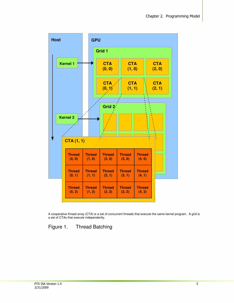
The host issues a succession of kernel invocations to the device. Each kernel is executed as a batch of threads organized as a grid of CTAs (Figure 1).
Chapter 2. Programming Model
PTX ISA Version 1.4 5 3/31/2009
A cooperative thread array (CTA) is a set of concurrent threads that execute the same kernel program. A grid is a set of CTAs that execute independently.
Figure 1. Thread Batching
Host
Kernel 1
Kernel 2
GPU
Grid 1
CTA (0, 0)
CTA (1, 0)
CTA (2, 0)
CTA (0, 1)
CTA (1, 1)
CTA (2, 1)
Grid 2
CTA (1, 1)
Thread (0, 1)
Thread(1, 1)
Thread (2, 1)
Thread (3, 1)
Thread(4, 1)
Thread (0, 2)
Thread(1, 2)
Thread (2, 2)
Thread (3, 2)
Thread(4, 2)
Thread
(0, 0)
Thread
(1, 0)
Thread
(2, 0)
Thread
(3, 0)
Thread
(4, 0)
Chapter 2: Programming Model
6 PTX ISA Version 1.4 3/31/2009
2.3. Memory Hierarchy
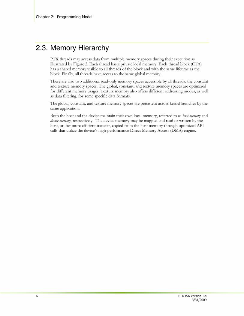
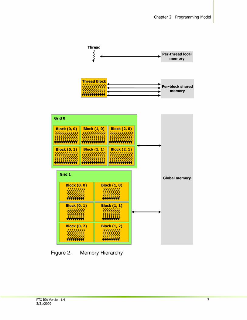
PTX threads may access data from multiple memory spaces during their execution as illustrated by Figure 2. Each thread has a private local memory. Each thread block (CTA) has a shared memory visible to all threads of the block and with the same lifetime as the block. Finally, all threads have access to the same global memory.
There are also two additional read-only memory spaces accessible by all threads: the constant and texture memory spaces. The global, constant, and texture memory spaces are optimized for different memory usages. Texture memory also offers different addressing modes, as well as data filtering, for some specific data formats.
The global, constant, and texture memory spaces are persistent across kernel launches by the same application.
Both the host and the device maintain their own local memory, referred to as host memory and device memory, respectively. The device memory may be mapped and read or written by the host, or, for more efficient transfer, copied from the host memory through optimized API calls that utilize the device’s high-performance Direct Memory Access (DMA) engine.
Chapter 2. Programming Model
PTX ISA Version 1.4 7 3/31/2009
Figure 2. Memory Hierarchy
Global memory
Grid 0
Block (2, 1) Block (1, 1) Block (0, 1)
Block (2, 0) Block (1, 0) Block (0, 0)
Grid 1
Block (1, 1)
Block (1, 0)
Block (1, 2)
Block (0, 1)
Block (0, 0)
Block (0, 2)
Thread Block
Per-block shared memory
Thread
Per-thread local
memory

Chapter 2: Programming Model
8 PTX ISA Version 1.4 3/31/2009
This page is blank.
PTX ISA Version 1.4 9 3/31/2009
Chapter 3.
Parallel Thread Execution Machine Model
3.1. A Set of SIMT Multiprocessors with On-Chip Shared Memory
The Tesla architecture is built around a scalable array of multithreaded Streaming Multiprocessors (SMs). When a host program invokes a kernel grid, the blocks of the grid are enumerated and distributed to multiprocessors with available execution capacity. The threads of a thread block execute concurrently on one multiprocessor. As thread blocks terminate, new blocks are launched on the vacated multiprocessors.
A multiprocessor consists of multiple Scalar Processor (SP) cores, a multithreaded instruction unit, and on-chip shared memory. The multiprocessor creates, manages, and executes concurrent threads in hardware with zero scheduling overhead. It implements a single-instruction barrier synchronization. Fast barrier synchronization together with lightweight thread creation and zero-overhead thread scheduling efficiently support very fine-grained parallelism, allowing, for example, a low granularity decomposition of problems by assigning one thread to each data element (such as a pixel in an image, a voxel in a volume, a cell in a grid-based computation).
To manage hundreds of threads running several different programs, the multiprocessor employs a new architecture we call SIMT (single-instruction, multiple-thread). The multiprocessor maps each thread to one scalar processor core, and each scalar thread executes independently with its own instruction address and register state. The multiprocessor SIMT unit creates, manages, schedules, and executes threads in groups of parallel threads called warps. (This term originates from weaving, the first parallel thread technology.) Individual threads composing a SIMT warp start together at the same program address but are otherwise free to branch and execute independently.
When a multiprocessor is given one or more thread blocks to execute, it splits them into warps that get scheduled by the SIMT unit. The way a block is split into warps is always the same; each warp contains threads of consecutive, increasing thread IDs with the first warp containing thread 0.
At every instruction issue time, the SIMT unit selects a warp that is ready to execute and issues the next instruction to the active threads of the warp. A warp executes one common instruction at a time, so full efficiency is realized when all threads of a warp agree on their execution path. If threads of a warp diverge via a data-dependent conditional branch, the warp serially executes each branch path taken, disabling threads that are not on that path, and when all paths complete, the threads converge back to the same execution path. Branch divergence occurs only within a warp; different warps execute independently regardless of whether they are executing common or disjointed code paths.
Chapter 3: Parallel Thread Execution Machine Model
10 PTX ISA Version 1.4 3/31/2009
SIMT architecture is akin to SIMD (Single Instruction, Multiple Data) vector organizations in that a single instruction controls multiple processing elements. A key difference is that SIMD vector organizations expose the SIMD width to the software, whereas SIMT instructions specify the execution and branching behavior of a single thread. In contrast with SIMD vector machines, SIMT enables programmers to write thread-level parallel code for independent, scalar threads, as well as data-parallel code for coordinated threads. For the purposes of correctness, the programmer can essentially ignore the SIMT behavior; however, substantial performance improvements can be realized by taking care that the code seldom requires threads in a warp to diverge. In practice, this is analogous to the role of cache lines in traditional code: Cache line size can be safely ignored when designing for correctness but must be considered in the code structure when designing for peak performance. Vector architectures, on the other hand, require the software to coalesce loads into vectors and manage divergence manually.
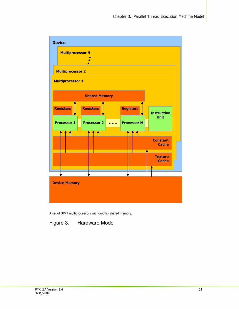
As illustrated by Figure 3, each multiprocessor has on-chip memory of the four following types:
• One set of local 32-bit registers per processor,
• A parallel data cache or shared memory that is shared by all scalar processor cores and is where the shared memory space resides,
• A read-only constant cache that is shared by all scalar processor cores and speeds up reads from the constant memory space, which is a read-only region of device memory,
• A read-only texture cache that is shared by all scalar processor cores and speeds up reads from the texture memory space, which is a read-only region of device memory; each multiprocessor accesses the texture cache via a texture unit that implements the various addressing modes and data filtering.
The local and global memory spaces are read-write regions of device memory and are not cached.
How many blocks a multiprocessor can process at once depends on how many registers per thread and how much shared memory per block are required for a given kernel since the multiprocessor’s registers and shared memory are split among all the threads of the batch of blocks. If there are not enough registers or shared memory available per multiprocessor to process at least one block, the kernel will fail to launch. A multiprocessor can execute as many as eight thread blocks concurrently.
If a non-atomic instruction executed by a warp writes to the same location in global or shared memory for more than one of the threads of the warp, the number of serialized writes that occur to that location and the order in which they occur is undefined, but one of the writes is guaranteed to succeed. If an atomic instruction executed by a warp reads, modifies, and writes to the same location in global memory for more than one of the threads of the warp, each read, modify, write to that location occurs and they are all serialized, but the order in which they occur is undefined.
Chapter 3. Parallel Thread Execution Machine Model
PTX ISA Version 1.4 11 3/31/2009
A set of SIMT multiprocessors with on-chip shared memory.
Figure 3. Hardware Model
Device
Multiprocessor N
Multiprocessor 2
Multiprocessor 1
Device Memory
Shared Memory
Instruction Unit
Processor 1
Registers
… Processor 2
Registers
Processor M
Registers
Constant Cache
Texture Cache
Chapter 3: Parallel Thread Execution Machine Model
12 PTX ISA Version 1.4 3/31/2009
This page is blank.
PTX ISA Version 1.4 13 3/31/2009
Chapter 4.
Syntax
PTX programs are a collection of text source files. PTX source files have an assembly-language style syntax with instruction operation codes and operands. Pseudo-operations specify symbol and addressing management. The ptxas program assembles PTX source files to produce corresponding binary object files.
4.1. Source Format
Source files are ASCII text. Lines are separated by the newline character (‘\n’).
All whitespace characters are equivalent; whitespace is ignored except for its use in separating tokens in the language.
The C preprocessor cpp may be used to process PTX source files. Lines beginning with # are preprocessor directives. The following are common preprocessor directives:
#include, #define, #if, #ifdef, #else, #endif, #line, #file
C: A Reference Manual by Harbison and Steele provides a good description of the C preprocessor.
PTX is case sensitive and uses lowercase for keywords.
Each PTX file must begin with a .version directive specifying the PTX language version, followed by a .target directive specifying the target architecture assumed. See Section 9 for a more information on these directives.
4.2. Comments
Comments in PTX follow C/C++ syntax, using non-nested /* and */ for comments that may span multiple lines, and using // to begin a comment that extends to the end of the current line.
Comments in PTX are treated as whitespace.
Chapter 4: Syntax
14 PTX ISA Version 1.4 3/31/2009
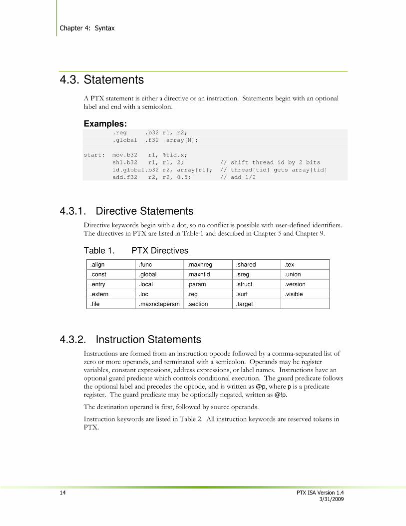
4.3. Statements
A PTX statement is either a directive or an instruction. Statements begin with an optional label and end with a semicolon.
Examples: .reg .b32 r1, r2;
.global .f32 array[N];
start: mov.b32 r1, %tid.x;
shl.b32 r1, r1, 2; // shift thread id by 2 bits
ld.global.b32 r2, array[r1]; // thread[tid] gets array[tid]
add.f32 r2, r2, 0.5; // add 1/2
4.3.1. Directive Statements
Directive keywords begin with a dot, so no conflict is possible with user-defined identifiers. The directives in PTX are listed in Table 1 and described in Chapter 5 and Chapter 9.
Table 1. PTX Directives
.align .func .maxnreg .shared .tex
.const .global .maxntid .sreg .union
.entry .local .param .struct .version
.extern .loc .reg .surf .visible
.file .maxnctapersm .section .target
4.3.2. Instruction Statements Instructions are formed from an instruction opcode followed by a comma-separated list of zero or more operands, and terminated with a semicolon. Operands may be register variables, constant expressions, address expressions, or label names. Instructions have an optional guard predicate which controls conditional execution. The guard predicate follows the optional label and precedes the opcode, and is written as @p, where p is a predicate register. The guard predicate may be optionally negated, written as @!p.
The destination operand is first, followed by source operands.
Instruction keywords are listed in Table 2. All instruction keywords are reserved tokens in PTX.

Chapter 4. Syntax
PTX ISA Version 1.4 15 3/31/2009
Table 2. Reserved Instruction Keywords
abs cvt min ret st
add div mov rsqrt sub
addc ex2 mul sad subc
and exit mul24 selp tex
atom fma neg set trap
bar ld not setp vote
bra lg2 or shl xor
brkpt mad pmevent shr
call mad24 rcp sin
cnot max red slct
cos membar rem sqrt
4.4. Identifiers
User-defined identifiers follow extended C++ rules: they either start with a letter followed by zero or more letters, digits, underscore, or dollar characters; or they start with an underscore, dollar, or percentage character followed by one or more letters, digits, underscore, or dollar characters:
followsym: [a-zA-Z0-9_$] identifier: [a-zA-Z]{followsym}* | {[_$%]{followsym}+
PTX does not specify a maximum length for identifiers and suggests that all implementations support a minimum length of at least 1024 characters.
Many high-level languages such as C and C++ follow similar rules for identifier names, except that the percentage sign is not allowed. PTX allows the percentage sign as the first character of an identifier. The percentage sign can be used to avoid name conflicts, e.g. between user-defined variable names and compiler-generated names.
PTX predefines one constant and a small number of special registers that begin with the percentage sign, listed in Table 3.
Table 3. Predefined Identifiers
%tid %ntid %laneid %warpid
%ctaid %nctaid %smid %nsmid
%gridid %clock WARP_SZ %pm0, …, %pm3
Chapter 4: Syntax
16 PTX ISA Version 1.4 3/31/2009
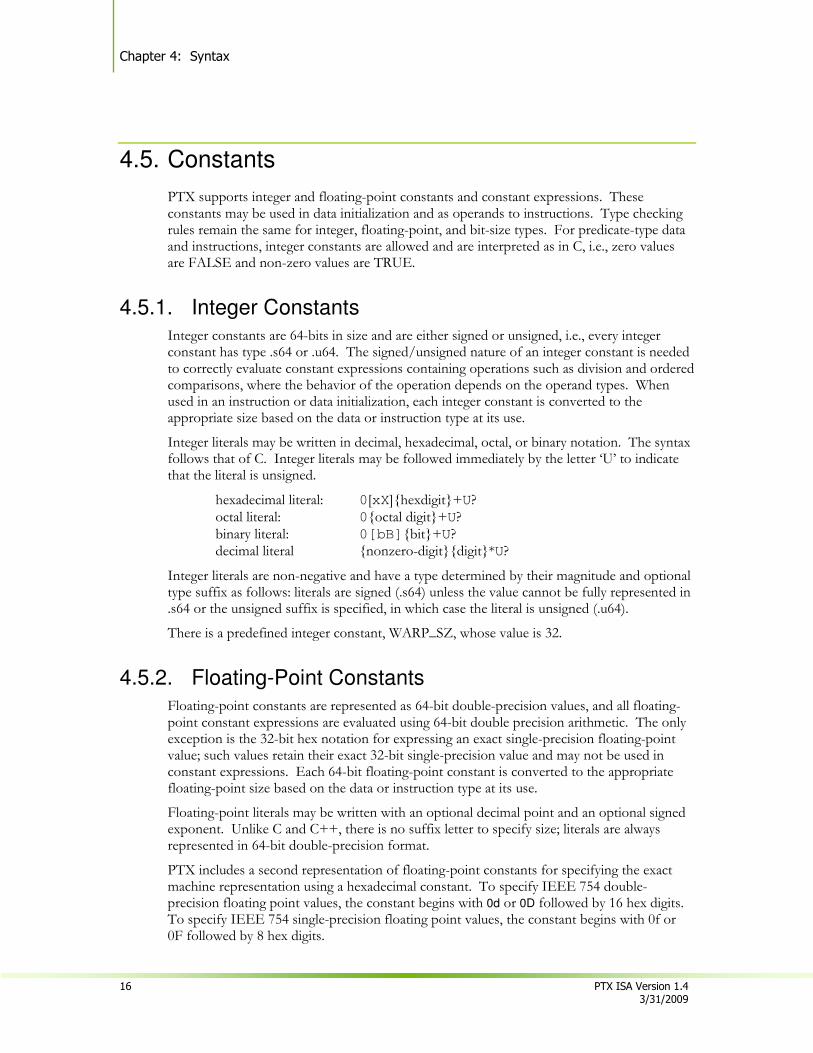
4.5. Constants
PTX supports integer and floating-point constants and constant expressions. These constants may be used in data initialization and as operands to instructions. Type checking rules remain the same for integer, floating-point, and bit-size types. For predicate-type data and instructions, integer constants are allowed and are interpreted as in C, i.e., zero values are FALSE and non-zero values are TRUE.
4.5.1. Integer Constants Integer constants are 64-bits in size and are either signed or unsigned, i.e., every integer constant has type .s64 or .u64. The signed/unsigned nature of an integer constant is needed to correctly evaluate constant expressions containing operations such as division and ordered comparisons, where the behavior of the operation depends on the operand types. When used in an instruction or data initialization, each integer constant is converted to the appropriate size based on the data or instruction type at its use.
Integer literals may be written in decimal, hexadecimal, octal, or binary notation. The syntax follows that of C. Integer literals may be followed immediately by the letter ‘U’ to indicate that the literal is unsigned.
hexadecimal literal: 0[xX]{hexdigit}+U? octal literal: 0{octal digit}+U? binary literal: 0[bB]{bit}+U? decimal literal {nonzero-digit}{digit}*U?
Integer literals are non-negative and have a type determined by their magnitude and optional type suffix as follows: literals are signed (.s64) unless the value cannot be fully represented in .s64 or the unsigned suffix is specified, in which case the literal is unsigned (.u64).
There is a predefined integer constant, WARP_SZ, whose value is 32.
4.5.2. Floating-Point Constants Floating-point constants are represented as 64-bit double-precision values, and all floating-point constant expressions are evaluated using 64-bit double precision arithmetic. The only exception is the 32-bit hex notation for expressing an exact single-precision floating-point value; such values retain their exact 32-bit single-precision value and may not be used in constant expressions. Each 64-bit floating-point constant is converted to the appropriate floating-point size based on the data or instruction type at its use.
Floating-point literals may be written with an optional decimal point and an optional signed exponent. Unlike C and C++, there is no suffix letter to specify size; literals are always represented in 64-bit double-precision format.
PTX includes a second representation of floating-point constants for specifying the exact machine representation using a hexadecimal constant. To specify IEEE 754 double-precision floating point values, the constant begins with 0d or 0D followed by 16 hex digits. To specify IEEE 754 single-precision floating point values, the constant begins with 0f or 0F followed by 8 hex digits.
Chapter 4. Syntax
PTX ISA Version 1.4 17 3/31/2009
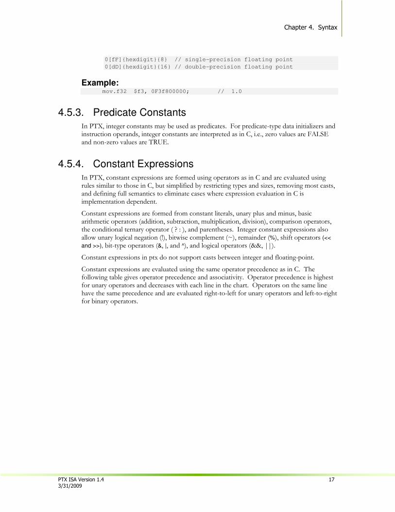
0[fF]{hexdigit}{8} // single-precision floating point
0[dD]{hexdigit}{16} // double-precision floating point
Example: mov.f32 $f3, 0F3f800000; // 1.0
4.5.3. Predicate Constants
In PTX, integer constants may be used as predicates. For predicate-type data initializers and instruction operands, integer constants are interpreted as in C, i.e., zero values are FALSE and non-zero values are TRUE.
4.5.4. Constant Expressions
In PTX, constant expressions are formed using operators as in C and are evaluated using rules similar to those in C, but simplified by restricting types and sizes, removing most casts, and defining full semantics to eliminate cases where expression evaluation in C is implementation dependent.
Constant expressions are formed from constant literals, unary plus and minus, basic arithmetic operators (addition, subtraction, multiplication, division), comparison operators, the conditional ternary operator ( ? : ), and parentheses. Integer constant expressions also allow unary logical negation (!), bitwise complement (~), remainder (%), shift operators (<<
and >>), bit-type operators (&, |, and ^), and logical operators (&&, ||).
Constant expressions in ptx do not support casts between integer and floating-point.
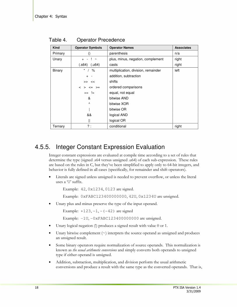
Constant expressions are evaluated using the same operator precedence as in C. The following table gives operator precedence and associativity. Operator precedence is highest for unary operators and decreases with each line in the chart. Operators on the same line have the same precedence and are evaluated right-to-left for unary operators and left-to-right for binary operators.
Chapter 4: Syntax
18 PTX ISA Version 1.4 3/31/2009
Table 4. Operator Precedence
Kind Operator Symbols Operator Names Associates
Primary () parenthesis n/a
Unary + - ! ~ plus, minus, negation, complement right
(.s64) (.u64) casts right
Binary * / % multiplication, division, remainder left
+ - addition, subtraction
>> << shifts
< > <= >= ordered comparisons
== != equal, not equal
& bitwise AND
^ bitwise XOR
| bitwise OR
&& logical AND
|| logical OR
Ternary ? : conditional right
4.5.5. Integer Constant Expression Evaluation Integer constant expressions are evaluated at compile time according to a set of rules that determine the type (signed .s64 versus unsigned .u64) of each sub-expression. These rules are based on the rules in C, but they’ve been simplified to apply only to 64-bit integers, and behavior is fully defined in all cases (specifically, for remainder and shift operators).
• Literals are signed unless unsigned is needed to prevent overflow, or unless the literal uses a ‘U’ suffix.
Example: 42, 0x1234, 0123 are signed.
Example: 0xFABC123400000000, 42U, 0x1234U are unsigned.
• Unary plus and minus preserve the type of the input operand.
Example: +123, -1, -(-42) are signed
Example: -1U, -0xFABC123400000000 are unsigned.
• Unary logical negation (!) produces a signed result with value 0 or 1.
• Unary bitwise complement (~) interprets the source operand as unsigned and produces an unsigned result.
• Some binary operators require normalization of source operands. This normalization is known as the usual arithmetic conversions and simply converts both operands to unsigned type if either operand is unsigned.
• Addition, subtraction, multiplication, and division perform the usual arithmetic conversions and produce a result with the same type as the converted operands. That is,
Chapter 4. Syntax
PTX ISA Version 1.4 19 3/31/2009
the operands and result are unsigned if either source operand is unsigned, and is otherwise signed.
• Remainder (%) interprets the operands as unsigned. Note that this differs from C, which allows a negative divisor but defines the behavior to be implementation dependent.
• Left and right shift interpret the second operand as unsigned and produce a result with the same type as the first operand. Note that the behavior of right-shift is determined by the type of the first operand: right shift of a signed value is arithmetic and preserves the sign, and right shift of an unsigned value is logical and shifts in a zero bit.
• AND (&), OR (|), and XOR (^) perform the usual arithmetic conversions and produce a result with the same type as the converted operands.
• AND_OP (&&), OR_OP (||), Equal (==), and Not_Equal (!=) produce a signed result. The result value is 0 or 1.
• Ordered comparisons (<, <=, >, >=) perform the usual arithmetic conversions on source operands and produce a signed result. The result value is 0 or 1.
• Casting of expressions to signed or unsigned is supported using (.s64) and (.u64) casts.
• For the conditional operator ( ? : ) , the first operand must be an integer, and the second and third operands are either both integers or both floating-point. The usual arithmetic conversions are performed on the second and third operands, and the result type is the same as the converted type.
Chapter 4: Syntax
20 PTX ISA Version 1.4 3/31/2009
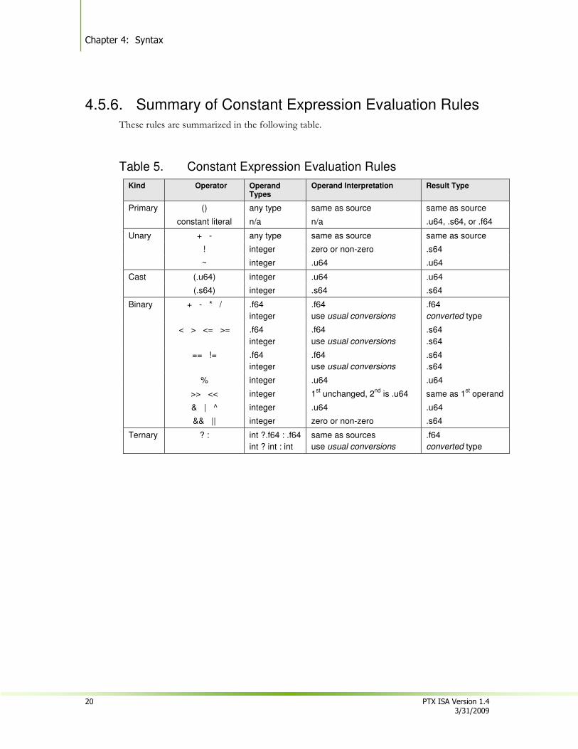
4.5.6. Summary of Constant Expression Evaluation Rules
These rules are summarized in the following table.
Table 5. Constant Expression Evaluation Rules
Kind Operator Operand Types
Operand Interpretation Result Type
Primary () any type same as source same as source
constant literal n/a n/a .u64, .s64, or .f64
Unary + - any type same as source same as source
! integer zero or non-zero .s64
~ integer .u64 .u64
Cast (.u64) integer .u64 .u64
(.s64) integer .s64 .s64
Binary + - * / .f64
integer
.f64
use usual conversions
.f64
converted type
< > <= >= .f64
integer
.f64
use usual conversions
.s64
.s64
== != .f64
integer
.f64
use usual conversions
.s64
.s64
% integer .u64 .u64
>> << integer 1st unchanged, 2
nd is .u64 same as 1
st operand
& | ^ integer .u64 .u64
&& || integer zero or non-zero .s64
Ternary ? : int ?.f64 : .f64
int ? int : int
same as sources
use usual conversions
.f64
converted type
PTX ISA Version 1.4 21 3/31/2009
Chapter 5.
State Spaces, Types, and Variables
While the specific resources available in a given target GPU will vary, the kinds of resources will be common across platforms, and these resources are abstracted in PTX through state spaces and data types.
5.1. State Spaces
A state space is a storage area with particular characteristics. All variables reside in some state space. The characteristics of a state space include its size, addressability, access speed, access rights, and level of sharing between threads.
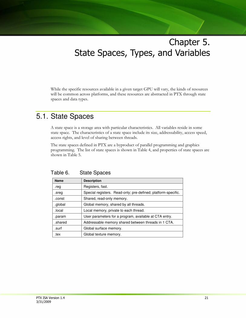
The state spaces defined in PTX are a byproduct of parallel programming and graphics programming. The list of state spaces is shown in Table 4, and properties of state spaces are shown in Table 5.
Table 6. State Spaces
Name Description
.reg Registers, fast.
.sreg Special registers. Read-only; pre-defined; platform-specific.
.const Shared, read-only memory.
.global Global memory, shared by all threads.
.local Local memory, private to each thread.
.param User parameters for a program, available at CTA entry.
.shared Addressable memory shared between threads in 1 CTA.
.surf Global surface memory.
.tex Global texture memory.
Chapter 5: State Spaces, Types, and Variables
22 PTX ISA Version 1.4 3/31/2009
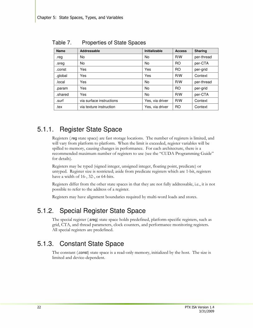
Table 7. Properties of State Spaces
Name Addressable Initializable Access Sharing
.reg No No R/W per-thread
.sreg No No RO per-CTA
.const Yes Yes RO per-grid
.global Yes Yes R/W Context
.local Yes No R/W per-thread
.param Yes No RO per-grid
.shared Yes No R/W per-CTA
.surf via surface instructions Yes, via driver R/W Context
.tex via texture instruction Yes, via driver RO Context
5.1.1. Register State Space
Registers (.reg state space) are fast storage locations. The number of registers is limited, and will vary from platform to platform. When the limit is exceeded, register variables will be spilled to memory, causing changes in performance. For each architecture, there is a recommended maximum number of registers to use (see the “CUDA Programming Guide” for details).
Registers may be typed (signed integer, unsigned integer, floating point, predicate) or untyped. Register size is restricted; aside from predicate registers which are 1-bit, registers have a width of 16-, 32-, or 64-bits.
Registers differ from the other state spaces in that they are not fully addressable, i.e., it is not possible to refer to the address of a register.
Registers may have alignment boundaries required by multi-word loads and stores.
5.1.2. Special Register State Space The special register (.sreg) state space holds predefined, platform-specific registers, such as grid, CTA, and thread parameters, clock counters, and performance monitoring registers. All special registers are predefined.
5.1.3. Constant State Space The constant (.const) state space is a read-only memory, initialized by the host. The size is limited and device-dependent.
Chapter 5. State Spaces, Types, and Variables
PTX ISA Version 1.4 23 3/31/2009
5.1.4. Global State Space
The global (.global) state space is memory that is accessible by all threads in a context. It is the mechanism by which different CTAs and different grids can communicate. Use ld.global, st.global, and atom.global to access global variables.
For any thread in a context, all addresses are in global memory are shared.
Global memory is not sequentially consistent. Consider the case where one thread executes the following two assignments:
a = a + 1;
b = b – 1;
If another thread sees the variable b change, the store operation updating a may still be in flight. This reiterates the kind of parallelism available in machines that run PTX. Threads must be able to do their work without waiting for other threads to do theirs, as in lock-free and wait-free style programming.
Sequential consistency is provided by the bar.sync instruction. Threads wait at the barrier until all threads in the CTA have arrived. All memory writes prior to the bar.sync instruction are guaranteed to be visible to any reads after the barrier instruction.
5.1.5. Local State Space The local state space (.local) is private memory for each thread to keep its own data. It is typically standard memory with cache. The size is limited, as it must be allocated on a per-thread basis. Use ld.local and st.local to access local variables.
5.1.6. Parameter State Space
The parameter (.param) state space provides addressable user parameters to CTAs. User parameters begin at address zero, and the address space is shared across CTAs within a grid. Variables in the .param state space may be defined only within an entry function, and each variable is mapped to the next available aligned location in .param space, where alignment is based on the variable’s size.
The location of parameter space is implementation specific. For example, in some implementations, parameter space resides in global memory. No access protection is provided between parameter and global space in this case.
5.1.7. Shared State Space The shared (.shared) state space is a per-CTA region of memory for threads in a CTA to share data. An address in shared memory can be read and written by any thread in a CTA. Use ld.shared and st.shared to access shared variables.
Shared memory typically has some optimizations to support the sharing. One example is broadcast; where all threads read from the same address. Another is sequential access from sequential threads.
Chapter 5: State Spaces, Types, and Variables
24 PTX ISA Version 1.4 3/31/2009
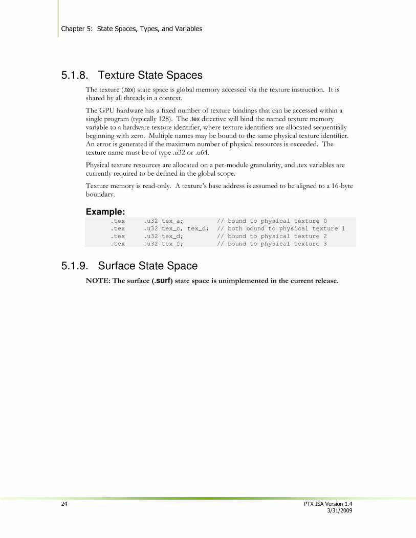
5.1.8. Texture State Spaces
The texture (.tex) state space is global memory accessed via the texture instruction. It is shared by all threads in a context.
The GPU hardware has a fixed number of texture bindings that can be accessed within a single program (typically 128). The .tex directive will bind the named texture memory variable to a hardware texture identifier, where texture identifiers are allocated sequentially beginning with zero. Multiple names may be bound to the same physical texture identifier. An error is generated if the maximum number of physical resources is exceeded. The texture name must be of type .u32 or .u64.
Physical texture resources are allocated on a per-module granularity, and .tex variables are currently required to be defined in the global scope.
Texture memory is read-only. A texture’s base address is assumed to be aligned to a 16-byte boundary.
Example: .tex .u32 tex_a; // bound to physical texture 0
.tex .u32 tex_c, tex_d; // both bound to physical texture 1
.tex .u32 tex_d; // bound to physical texture 2
.tex .u32 tex_f; // bound to physical texture 3
5.1.9. Surface State Space
NOTE: The surface (.surf) state space is unimplemented in the current release.
Chapter 5. State Spaces, Types, and Variables
PTX ISA Version 1.4 25 3/31/2009
5.2. Types
5.2.1. Fundamental Types In PTX, the fundamental types reflect the native data types supported by the target architectures. A fundamental type specifies both a basic type and a size. Register variables are always of a fundamental type, and instructions operate on these types. The same type-size specifiers are used for both variable definitions and for typing instructions, so their names are intentionally short.
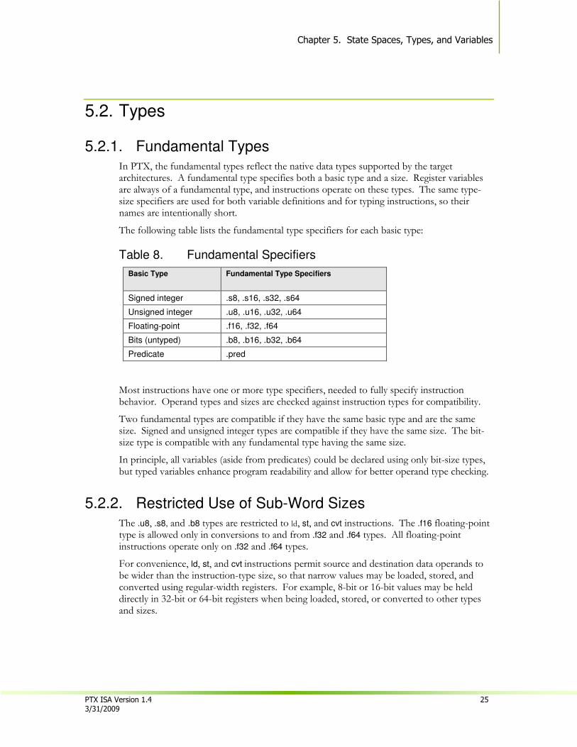
The following table lists the fundamental type specifiers for each basic type:
Table 8. Fundamental Specifiers
Basic Type
Fundamental Type Specifiers
Signed integer .s8, .s16, .s32, .s64
Unsigned integer .u8, .u16, .u32, .u64
Floating-point .f16, .f32, .f64
Bits (untyped) .b8, .b16, .b32, .b64
Predicate .pred
Most instructions have one or more type specifiers, needed to fully specify instruction behavior. Operand types and sizes are checked against instruction types for compatibility.
Two fundamental types are compatible if they have the same basic type and are the same size. Signed and unsigned integer types are compatible if they have the same size. The bit-size type is compatible with any fundamental type having the same size.
In principle, all variables (aside from predicates) could be declared using only bit-size types, but typed variables enhance program readability and allow for better operand type checking.
5.2.2. Restricted Use of Sub-Word Sizes The .u8, .s8, and .b8 types are restricted to ld, st, and cvt instructions. The .f16 floating-point type is allowed only in conversions to and from .f32 and .f64 types. All floating-point instructions operate only on .f32 and .f64 types.
For convenience, ld, st, and cvt instructions permit source and destination data operands to be wider than the instruction-type size, so that narrow values may be loaded, stored, and converted using regular-width registers. For example, 8-bit or 16-bit values may be held directly in 32-bit or 64-bit registers when being loaded, stored, or converted to other types and sizes.
Chapter 5: State Spaces, Types, and Variables
26 PTX ISA Version 1.4 3/31/2009
5.3. Variables
In PTX, a variable declaration describes both the variable’s type and its state space. In addition to fundamental types, PTX supports types for aggregate objects such as vectors, arrays, structures and unions.
NOTE: The current version of PTX does not implement structures or unions.
5.3.1. Variable Declarations All storage for data is specified with variable declarations. Every variable must reside in one of the state spaces enumerated in the previous section.
A variable declaration names the space in which the variable resides, its type and size, its name, an optional array size, an optional initializer, and an optional fixed address for the variable.
Predicate variables may only be declared in the register state space.
Examples: .global .u32 loc;
.reg .s32 i;
.const .f32 bias[] = {-1.0, 1.0};
.global .u8 bg[4] = {0, 0, 0, 0};
.reg .v4 .f32 accel;
.reg .pred p, q, r;
.struct float4 { .f32 v0,v1,v2,v3 }; // typedef
.global .struct float4 coord;
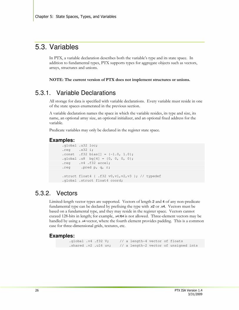
5.3.2. Vectors
Limited-length vector types are supported. Vectors of length 2 and 4 of any non-predicate fundamental type can be declared by prefixing the type with .v2 or .v4. Vectors must be based on a fundamental type, and they may reside in the register space. Vectors cannot exceed 128-bits in length; for example, .v4.f64 is not allowed. Three-element vectors may be handled by using a .v4 vector, where the fourth element provides padding. This is a common case for three-dimensional grids, textures, etc.
Examples: .global .v4 .f32 V; // a length-4 vector of floats
.shared .v2 .u16 uv; // a length-2 vector of unsigned ints
Chapter 5. State Spaces, Types, and Variables
PTX ISA Version 1.4 27 3/31/2009
5.3.3. Array Declarations
Array declarations are provided to allow the programmer to reserve space. To declare an array, the variable name is followed with dimensional declarations similar to fixed-size array declarations in C. The size of the dimension is either a constant expression, or is left empty, being determined by an array initializer. Here are some examples:
.local .u16 kernel[19][19];
.shared .u8 mailbox[128];
.global .s32 offset[][] = { {-1, 0}, {0, -1}, {1, 0}, {0, 1} };
The size of the array specifies how many elements should be reserved. For the kernel declaration above, 19*19 (361) halfwords are reserved (722 bytes).
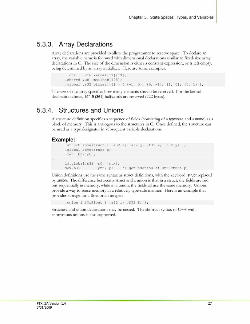
5.3.4. Structures and Unions A structure definition specifies a sequence of fields (consisting of a type/size and a name) as a block of memory. This is analogous to the structures in C. Once defined, the structure can be used as a type designator in subsequent variable declarations.
Example: .struct somestruct { .s32 i; .s32 j; .f32 x; .f32 y; };
.global somestruct p;
.reg .b32 ptr;
…
ld.global.s32 r0, [p.x];
mov.b32 ptr, p; // get address of structure p
Union definitions use the same syntax as struct definitions, with the keyword .struct replaced by .union. The difference between a struct and a union is that in a struct, the fields are laid out sequentially in memory, while in a union, the fields all use the same memory. Unions provide a way to reuse memory in a relatively type-safe manner. Here is an example that provides storage for a float or an integer:
.union intOrFloat { .s32 i; .f32 f; };
Structure and union declarations may be nested. The shortcut syntax of C++ with anonymous unions is also supported.
Chapter 5: State Spaces, Types, and Variables
28 PTX ISA Version 1.4 3/31/2009
5.3.5. Initializers
Declared variables may specify an initial value using a syntax similar to C/C++, where the variable name is followed by an equals sign and the initial value or values for the variable. A scalar takes a single value, while vectors and arrays take nested lists of values inside of curly braces (the nesting matches the dimensionality of the declaration). Structures take a list of values that matches the fields in a structure. Initializers are allowed for all types except .f16 and .pred.
Examples: .global .s32 n = 10;
.global .f32 blur_kernel[][]
= {{.05,.1,.05},{.1,.4,.1},{.05,.1,.05}};
.global .v4 .u8 rgba[3] = {{1,0,0,0}, {0,1,0,0}, {0,0,1,0}};
Currently, variable initialization is supported only for constant and global state spaces.
5.3.6. Alignment
Byte alignment of storage for all addressable variables can be specified in the variable declaration. Alignment is specified using an optional .align byte-count specifier immediately following the state-space specifier. The variable will be aligned to an address which is an integer multiple of byte-count. For arrays, structures, and unions, alignment specifies the address alignment for the starting address of the entire structure, not for individual elements.
Examples: // allocate array at 4-byte aligned address. Elements are bytes.
.const .align 4 .b8 bar[8] = {0,0,0,0,2,0,0,0};
Note that all PTX instructions that access memory require that the address be aligned to a multiple of the transfer size.
5.3.7. Parameterized Variable Names Since PTX supports virtual registers, it is quite common for a compiler frontend to generate a large number of register names. Rather than require explicit declaration of every name, PTX supports a syntax for creating a set of variables having a common prefix string appended with integer suffixes. For example, suppose a program uses a large number, say one hundred, of .b32 variables, named %r0, %r1, ..., %r99. These 100 register variables can be declared as follows:
.reg .b32 %r<100>; // declare %r0, %r1, …, %r99
This shorthand syntax may be used with any of the fundamental types and with any state space, and may be preceded by an alignment specifier. Array, structure, and union variables cannot be declared this way, nor are initializers permitted.
PTX ISA Version 1.4 29 3/31/2009
Chapter 6.
Instruction Operands
6.1. Operand Type Information
All operands in instructions have a known type from their declarations. Each operand type must be compatible with the type determined by the instruction template and instruction type. There is no automatic conversion between types.
The bit-size type is compatible with every type having the same size. Integer types of a common size are compatible with each other. Operands having type different from but compatible with the instruction type are silently cast to the instruction type.
6.2. Source Operands
The source operands are denoted in the instruction descriptions by the names a, b, and c. PTX describes a load-store machine, so operands for ALU instructions must all be in variables declared in the .reg register state space. For most operations, the sizes of the operands must be consistent.
The cvt (convert) instruction takes a variety of operand types and sizes, as its job is to convert from nearly any data type to any other data type (and size).
The ld, st, mov, and cvt instructions copy data from one location to another. Instructions ld and st move data from/to addressable state spaces to/from registers. The mov instruction copies data between registers.
Most instructions have an optional predicate guard that controls conditional execution, and a few instructions have additional predicate source operands. Predicate operands are denoted by the names p, q, r, s.
6.3. Destination Operands
PTX instructions that produce a single result store the result in the field denoted by d (for destination) in the instruction descriptions. The result operand is a scalar or vector variable in the register state space.
.
Chapter 6: Instruction Operands
30 PTX ISA Version 1.4 3/31/2009
6.4. Using Addresses, Arrays, Vectors, Structures, and Unions
Using scalar variables as operands is straightforward. The interesting capabilities begin with addresses, arrays, vectors, structures and unions.
6.4.1. Addresses as Operands Address arithmetic is performed using integer arithmetic and logical instructions. Examples include pointer arithmetic and pointer comparisons. All addresses and address computations are byte-based; there is no support for C-style pointer arithmetic.
The mov instruction can be used to move the address of a variable into a pointer. Load and store operations move data between registers and locations in addressable state spaces. The syntax is similar to that used in many assembly languages, where scalar variables are simply named and addresses are de-referenced by enclosing the address expression in square brackets. Address expressions include variable names, address registers, address register plus byte offset, and immediate address expressions which evaluate at compile-time to a constant address.
Here are a few examples:
.shared .u16 x;
.reg .u16 r0;
.global .v4 .f32 V;
.reg .v4 .f32 W;
.const .s32 tbl[256];
.reg .b32 p;
.reg .s32 q;
ld.shared.u16 r0,[x];
ld.gloal.v4.f32 W, [V];
ld.const.s32 q, [tbl+12];
mov.b32 p, tbl;

Chapter 6. Instruction Operands
PTX ISA Version 1.4 31 3/31/2009
6.4.2. Arrays as Operands
Arrays of all types can be declared, and the identifier becomes an address constant in the space where the array is declared. The size of the array is a constant in the program.
Array elements can be accessed using an explicitly calculated byte address, or by indexing into the array using square-bracket notation. The expression within square brackets is either a constant integer, a register variable, or a simple “register with constant offset” expression, where the offset is a constant expression that is either added or subtracted from a register variable. If more complicated indexing is desired, it must be written as an address calculation prior to use. Examples are
ld.global.u32 s, a[0];
ld.global.u32 s, a[N-1];
mov.u32 s, a[1]; // move address of a[1] into s
6.4.3. Vectors as Operands
Vector operands are supported by a limited subset of instructions, which include mov, ld, st, and tex. Vectors may also be passed as arguments to called functions.
Vector elements can be extracted from the vector with the suffixes .x, .y, .z and .w, as well as the typical color fields .r, .g, .b and .a.
A brace-enclosed list is used for pattern matching to pull apart vectors.
.reg .v4 .f32 V;
.reg .f32 a, b, c, d;
mov.v4.f32 {a,b,c,d}, V;
Vector loads and stores can be used to implement wide loads and stores, which may improve memory performance. The registers in the load/store operations can be a vector, or a brace-enclosed list of similarly typed scalars. Here are examples:
ld.global.v4.f32 {a,b,c,d}, [addr+offset];
ld.global.v2.u32 V2, [addr+offset2];
Elements in a brace-enclosed vector, say {Ra, Rb, Rc, Rd}, correspond to extracted elements as follows:
Ra = V.x = V.r
Rb = V.y = V.g
Rc = V.z = V.b
Rd = V.w = V.a
6.4.4. Structures and Unions as Operands
Structures and unions can only access their members; there are no instructions that take entire structures as operands.

Chapter 6: Instruction Operands
32 PTX ISA Version 1.4 3/31/2009
6.4.5. Labels and Function Names as Operands
Labels and function names can be used only in branch and call instructions, and in move instructions to get the address of the label or function into a register, for use in an indirect branch or call.
6.5. Type Conversion
All operands to all arithmetic, logic, and data movement instruction must be of the same type and size, except for operations where changing the size and/or type is part of the definition of the instruction. Operands of different sizes or types must be converted prior to the operation.
6.5.1. Scalar Conversions Table 6 shows what precision and format the cvt instruction uses given operands of differing types. For example, if a cvt.s32.u16 instruction is given a u16 source operand and s32 as a destination operand, the u16 is zero-extended to s32.
Conversions to floating-point that are beyond the range of floating-point numbers are represented with the maximum floating-point value (IEEE 754 Inf for f32 and f64, and ~131,000 for f16).
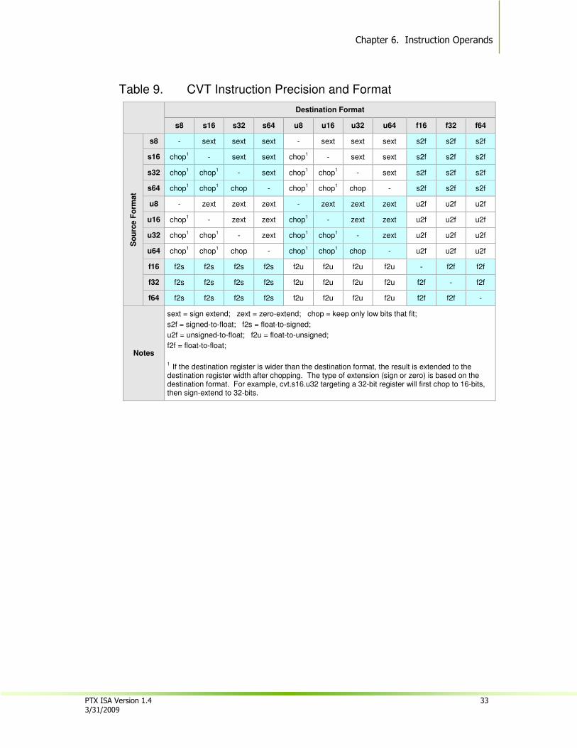
Chapter 6. Instruction Operands
PTX ISA Version 1.4 33 3/31/2009
Table 9. CVT Instruction Precision and Format
Destination Format
s8 s16 s32 s64 u8 u16 u32 u64 f16 f32 f64 S
ou
rce F
orm
at
s8 - sext sext sext - sext sext sext s2f s2f s2f
s16 chop1 - sext sext chop
1 - sext sext s2f s2f s2f
s32 chop1 chop
1 - sext chop
1 chop
1 - sext s2f s2f s2f
s64 chop1 chop
1 chop - chop
1 chop
1 chop - s2f s2f s2f
u8 - zext zext zext - zext zext zext u2f u2f u2f
u16 chop1 - zext zext chop
1 - zext zext u2f u2f u2f
u32 chop1 chop
1 - zext chop
1 chop
1 - zext u2f u2f u2f
u64 chop1 chop
1 chop - chop
1 chop
1 chop - u2f u2f u2f
f16 f2s f2s f2s f2s f2u f2u f2u f2u - f2f f2f
f32 f2s f2s f2s f2s f2u f2u f2u f2u f2f - f2f
f64 f2s f2s f2s f2s f2u f2u f2u f2u f2f f2f -
Notes
sext = sign extend; zext = zero-extend; chop = keep only low bits that fit;
s2f = signed-to-float; f2s = float-to-signed;
u2f = unsigned-to-float; f2u = float-to-unsigned;
f2f = float-to-float;
1
If the destination register is wider than the destination format, the result is extended to the destination register width after chopping. The type of extension (sign or zero) is based on the destination format. For example, cvt.s16.u32 targeting a 32-bit register will first chop to 16-bits, then sign-extend to 32-bits.
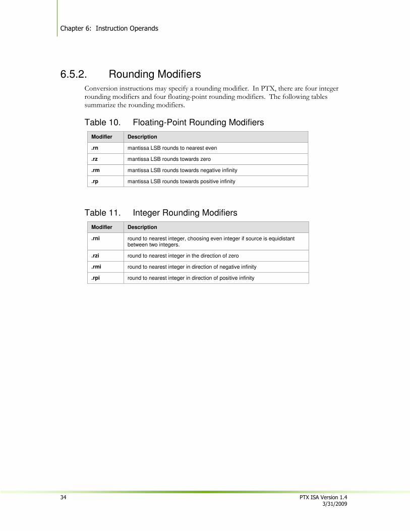
Chapter 6: Instruction Operands
34 PTX ISA Version 1.4 3/31/2009
6.5.2. Rounding Modifiers
Conversion instructions may specify a rounding modifier. In PTX, there are four integer rounding modifiers and four floating-point rounding modifiers. The following tables summarize the rounding modifiers.
Table 10. Floating-Point Rounding Modifiers
Modifier Description
.rn mantissa LSB rounds to nearest even
.rz mantissa LSB rounds towards zero
.rm mantissa LSB rounds towards negative infinity
.rp mantissa LSB rounds towards positive infinity
Table 11. Integer Rounding Modifiers
Modifier Description
.rni round to nearest integer, choosing even integer if source is equidistant between two integers.
.rzi round to nearest integer in the direction of zero
.rmi round to nearest integer in direction of negative infinity
.rpi round to nearest integer in direction of positive infinity

Chapter 6. Instruction Operands
PTX ISA Version 1.4 35 3/31/2009
6.6. Operand Costs
Operands from different state spaces affect the speed of an operation. Registers are fastest, while global memory is slowest. Much of the delay to memory can be hidden in a number of ways. The first is to have multiple threads of execution so that the hardware can issue a memory operation and then switch to other execution. Another way to hide latency is to issue the load instructions as early as possible, as execution is not blocked until the desired result is used in a subsequent (in time) instruction. The register in a store operation is available much more quickly. Table 11 gives estimates of the costs of using different kinds of memory.
Table 12. Cost Estimates for Accessing State-Spaces
Space Time Notes
Register 0
Shared 0
Constant 0 Amortized cost is low, first access is high
Local > 100 clocks
Parameter 0
Immediate 0
Global > 100 clocks
Texture > 100 clocks
Surface > 100 clocks
Chapter 6: Instruction Operands
36 PTX ISA Version 1.4 3/31/2009
This page is blank.
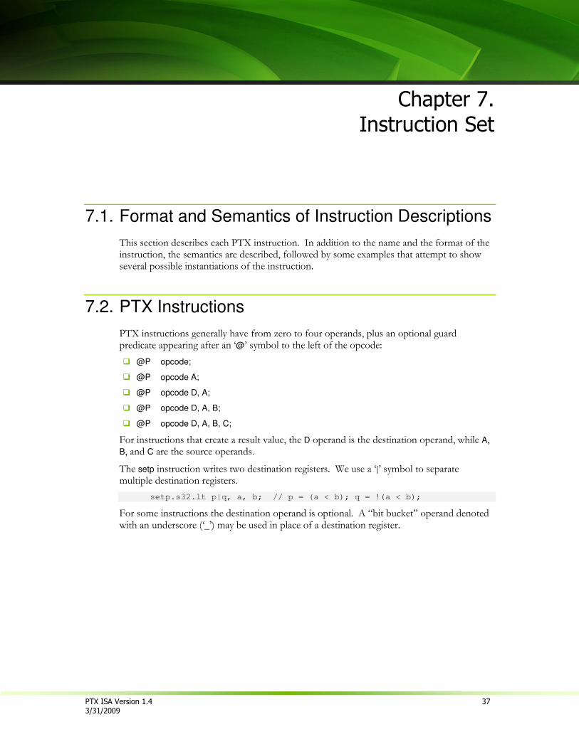
PTX ISA Version 1.4 37 3/31/2009
Chapter 7.
Instruction Set
7.1. Format and Semantics of Instruction Descriptions
This section describes each PTX instruction. In addition to the name and the format of the instruction, the semantics are described, followed by some examples that attempt to show several possible instantiations of the instruction.
7.2. PTX Instructions
PTX instructions generally have from zero to four operands, plus an optional guard predicate appearing after an ‘@’ symbol to the left of the opcode:
� @P opcode;
� @P opcode A;
� @P opcode D, A;
� @P opcode D, A, B;
� @P opcode D, A, B, C;
For instructions that create a result value, the D operand is the destination operand, while A, B, and C are the source operands.
The setp instruction writes two destination registers. We use a ‘|’ symbol to separate multiple destination registers.
setp.s32.lt p|q, a, b; // p = (a < b); q = !(a < b);
For some instructions the destination operand is optional. A “bit bucket” operand denoted with an underscore (‘_’) may be used in place of a destination register.
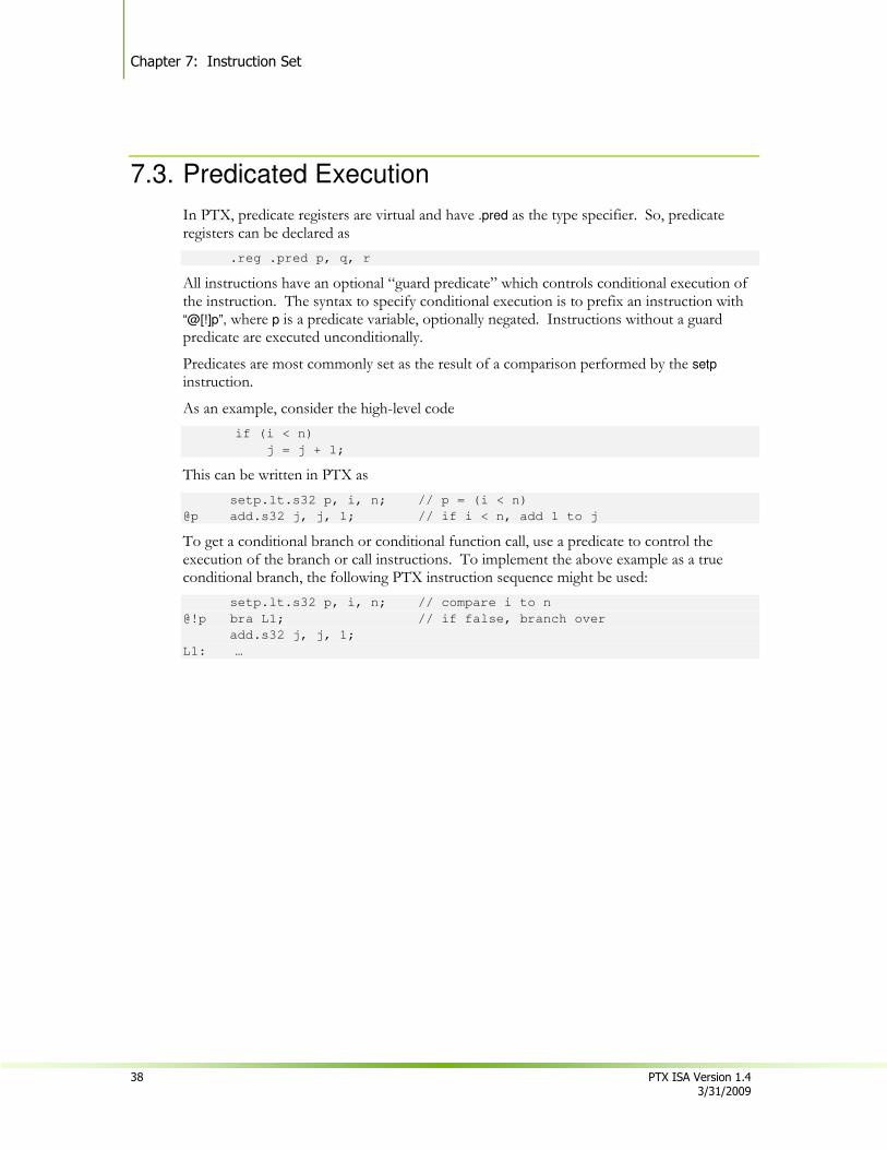
Chapter 7: Instruction Set
38 PTX ISA Version 1.4 3/31/2009
7.3. Predicated Execution
In PTX, predicate registers are virtual and have .pred as the type specifier. So, predicate registers can be declared as
.reg .pred p, q, r
All instructions have an optional “guard predicate” which controls conditional execution of the instruction. The syntax to specify conditional execution is to prefix an instruction with “@[!]p”, where p is a predicate variable, optionally negated. Instructions without a guard predicate are executed unconditionally.
Predicates are most commonly set as the result of a comparison performed by the setp
instruction.
As an example, consider the high-level code
if (i < n)
j = j + 1;
This can be written in PTX as
setp.lt.s32 p, i, n; // p = (i < n)
@p add.s32 j, j, 1; // if i < n, add 1 to j
To get a conditional branch or conditional function call, use a predicate to control the execution of the branch or call instructions. To implement the above example as a true conditional branch, the following PTX instruction sequence might be used:
setp.lt.s32 p, i, n; // compare i to n
@!p bra L1; // if false, branch over
add.s32 j, j, 1;
L1: …

Chapter 7. Instruction Set
PTX ISA Version 1.4 39 3/31/2009
7.3.1. Comparisons
7.3.1.1. Integer and Bit-Size Comparisons
The signed integer comparisons are the traditional eq (equal), ne (not-equal), lt (less-than), le (less-than-or-equal), gt (greater-than), and ge (greater-than-or-equal). The unsigned comparisons are eq, ne, lo (lower), ls (lower-or-same), hi (higher), and hs (higher-or-same). The bit-size comparisons are eq and ne; ordering comparisons are not defined for bit-size types. The following table shows the operators for signed integer, unsigned integer, and bit-size types.
Table 13. Operators for Signed Integer, Unsigned Integer, and Bit-Size Types
Meaning Signed Operator Unsigned Operator Bit-Size Operator
a == b EQ EQ EQ
a != b NE NE NE
a < b LT LO
a <= b LE LS
a > b GT HI
a >= b GE HS
7.3.1.2. Floating-Point Comparisons
The ordered comparisons are eq, ne, lt, le, gt, ge. If either operand is NaN, the result is false.
Table 14. Floating-Point Comparison Operators
Meaning Floating-Point Operator
a == b && !isNaN(a) && !isNaN(b) EQ
a != b && !isNaN(a) && !isNaN(b) NE
a < b && !isNaN(a) && !isNaN(b) LT
a <= b && !isNaN(a) && !isNaN(b) LE
a > b && !isNaN(a) && !isNaN(b) GT
a >= b && !isNaN(a) && !isNaN(b) GE
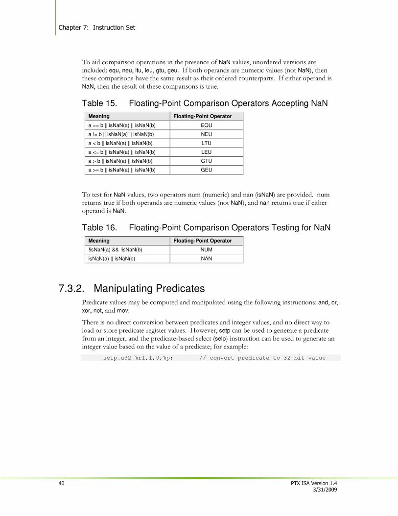
Chapter 7: Instruction Set
40 PTX ISA Version 1.4 3/31/2009
To aid comparison operations in the presence of NaN values, unordered versions are included: equ, neu, ltu, leu, gtu, geu. If both operands are numeric values (not NaN), then these comparisons have the same result as their ordered counterparts. If either operand is NaN, then the result of these comparisons is true.
Table 15. Floating-Point Comparison Operators Accepting NaN
Meaning Floating-Point Operator
a == b || isNaN(a) || isNaN(b) EQU
a != b || isNaN(a) || isNaN(b) NEU
a < b || isNaN(a) || isNaN(b) LTU
a <= b || isNaN(a) || isNaN(b) LEU
a > b || isNaN(a) || isNaN(b) GTU
a >= b || isNaN(a) || isNaN(b) GEU
To test for NaN values, two operators num (numeric) and nan (isNaN) are provided. num returns true if both operands are numeric values (not NaN), and nan returns true if either operand is NaN.
Table 16. Floating-Point Comparison Operators Testing for NaN
Meaning Floating-Point Operator
!isNaN(a) && !isNaN(b) NUM
isNaN(a) || isNaN(b) NAN
7.3.2. Manipulating Predicates
Predicate values may be computed and manipulated using the following instructions: and, or, xor, not, and mov.
There is no direct conversion between predicates and integer values, and no direct way to load or store predicate register values. However, setp can be used to generate a predicate from an integer, and the predicate-based select (selp) instruction can be used to generate an integer value based on the value of a predicate; for example:
selp.u32 %r1,1,0,%p; // convert predicate to 32-bit value
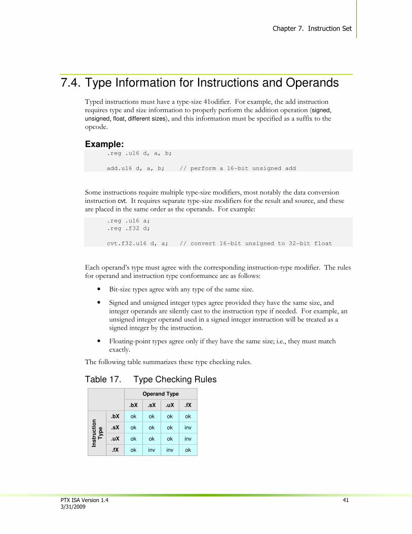
Chapter 7. Instruction Set
PTX ISA Version 1.4 41 3/31/2009
7.4. Type Information for Instructions and Operands
Typed instructions must have a type-size 41odifier. For example, the add instruction requires type and size information to properly perform the addition operation (signed, unsigned, float, different sizes), and this information must be specified as a suffix to the opcode.
Example: .reg .u16 d, a, b;
add.u16 d, a, b; // perform a 16-bit unsigned add
Some instructions require multiple type-size modifiers, most notably the data conversion instruction cvt. It requires separate type-size modifiers for the result and source, and these are placed in the same order as the operands. For example:
.reg .u16 a;
.reg .f32 d;
cvt.f32.u16 d, a; // convert 16-bit unsigned to 32-bit float
Each operand’s type must agree with the corresponding instruction-type modifier. The rules for operand and instruction type conformance are as follows:
• Bit-size types agree with any type of the same size.
• Signed and unsigned integer types agree provided they have the same size, and integer operands are silently cast to the instruction type if needed. For example, an unsigned integer operand used in a signed integer instruction will be treated as a signed integer by the instruction.
• Floating-point types agree only if they have the same size; i.e., they must match exactly.
The following table summarizes these type checking rules.
Table 17. Type Checking Rules
Operand Type
.bX .sX .uX .fX
Instr
ucti
on
T
yp
e
.bX ok ok ok ok
.sX ok ok ok inv
.uX ok ok ok inv
.fX ok inv inv ok
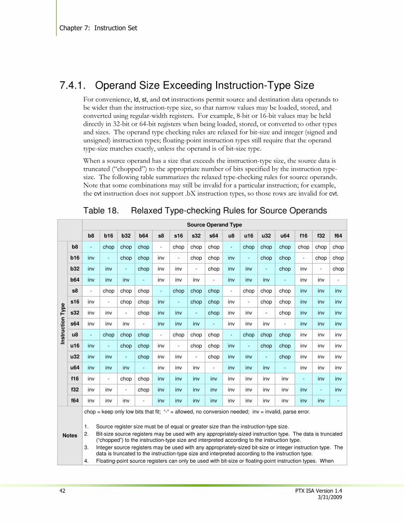
Chapter 7: Instruction Set
42 PTX ISA Version 1.4 3/31/2009
7.4.1. Operand Size Exceeding Instruction-Type Size
For convenience, ld, st, and cvt instructions permit source and destination data operands to be wider than the instruction-type size, so that narrow values may be loaded, stored, and converted using regular-width registers. For example, 8-bit or 16-bit values may be held directly in 32-bit or 64-bit registers when being loaded, stored, or converted to other types and sizes. The operand type checking rules are relaxed for bit-size and integer (signed and unsigned) instruction types; floating-point instruction types still require that the operand type-size matches exactly, unless the operand is of bit-size type.
When a source operand has a size that exceeds the instruction-type size, the source data is truncated (“chopped”) to the appropriate number of bits specified by the instruction type-size. The following table summarizes the relaxed type-checking rules for source operands. Note that some combinations may still be invalid for a particular instruction; for example, the cvt instruction does not support .bX instruction types, so those rows are invalid for cvt.
Table 18. Relaxed Type-checking Rules for Source Operands
Source Operand Type
b8 b16 b32 b64 s8 s16 s32 s64 u8 u16 u32 u64 f16 f32 f64
Instr
ucti
on
Typ
e
b8 - chop chop chop - chop chop chop - chop chop chop chop chop chop
b16 inv - chop chop inv - chop chop inv - chop chop - chop chop
b32 inv inv - chop inv inv - chop inv inv - chop inv - chop
b64 inv inv inv - inv inv inv - inv inv inv - inv inv -
s8 - chop chop chop - chop chop chop - chop chop chop inv inv inv
s16 inv - chop chop inv - chop chop inv - chop chop inv inv inv
s32 inv inv - chop inv inv - chop inv inv - chop inv inv inv
s64 inv inv inv - inv inv inv - inv inv inv - inv inv inv
u8 - chop chop chop - chop chop chop - chop chop chop inv inv inv
u16 inv - chop chop inv - chop chop inv - chop chop inv inv inv
u32 inv inv - chop inv inv - chop inv inv - chop inv inv inv
u64 inv inv inv - inv inv inv - inv inv inv - inv inv inv
f16 inv - chop chop inv inv inv inv inv inv inv inv - inv inv
f32 inv inv - chop inv inv inv inv inv inv inv inv inv - inv
f64 inv inv inv - inv inv inv inv inv inv inv inv inv inv -
Notes
chop = keep only low bits that fit; “-“ = allowed, no conversion needed; inv = invalid, parse error.
1. Source register size must be of equal or greater size than the instruction-type size.
2. Bit-size source registers may be used with any appropriately-sized instruction type. The data is truncated (“chopped”) to the instruction-type size and interpreted according to the instruction type.
3. Integer source registers may be used with any appropriately-sized bit-size or integer instruction type. The data is truncated to the instruction-type size and interpreted according to the instruction type.
4. Floating-point source registers can only be used with bit-size or floating-point instruction types. When
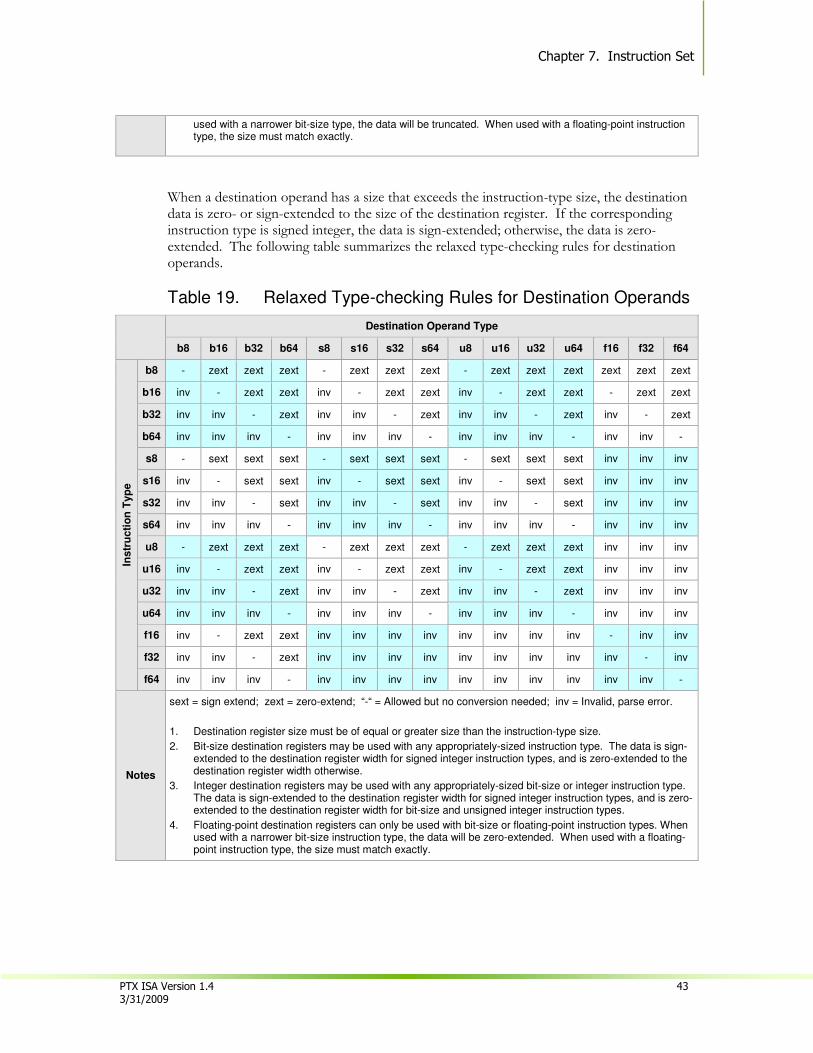
Chapter 7. Instruction Set
PTX ISA Version 1.4 43 3/31/2009
used with a narrower bit-size type, the data will be truncated. When used with a floating-point instruction type, the size must match exactly.
When a destination operand has a size that exceeds the instruction-type size, the destination data is zero- or sign-extended to the size of the destination register. If the corresponding instruction type is signed integer, the data is sign-extended; otherwise, the data is zero-extended. The following table summarizes the relaxed type-checking rules for destination operands.
Table 19. Relaxed Type-checking Rules for Destination Operands
Destination Operand Type
b8 b16 b32 b64 s8 s16 s32 s64 u8 u16 u32 u64 f16 f32 f64
Instr
ucti
on
Typ
e
b8 - zext zext zext - zext zext zext - zext zext zext zext zext zext
b16 inv - zext zext inv - zext zext inv - zext zext - zext zext
b32 inv inv - zext inv inv - zext inv inv - zext inv - zext
b64 inv inv inv - inv inv inv - inv inv inv - inv inv -
s8 - sext sext sext - sext sext sext - sext sext sext inv inv inv
s16 inv - sext sext inv - sext sext inv - sext sext inv inv inv
s32 inv inv - sext inv inv - sext inv inv - sext inv inv inv
s64 inv inv inv - inv inv inv - inv inv inv - inv inv inv
u8 - zext zext zext - zext zext zext - zext zext zext inv inv inv
u16 inv - zext zext inv - zext zext inv - zext zext inv inv inv
u32 inv inv - zext inv inv - zext inv inv - zext inv inv inv
u64 inv inv inv - inv inv inv - inv inv inv - inv inv inv
f16 inv - zext zext inv inv inv inv inv inv inv inv - inv inv
f32 inv inv - zext inv inv inv inv inv inv inv inv inv - inv
f64 inv inv inv - inv inv inv inv inv inv inv inv inv inv -
Notes
sext = sign extend; zext = zero-extend; “-“ = Allowed but no conversion needed; inv = Invalid, parse error.
1. Destination register size must be of equal or greater size than the instruction-type size.
2. Bit-size destination registers may be used with any appropriately-sized instruction type. The data is sign-extended to the destination register width for signed integer instruction types, and is zero-extended to the destination register width otherwise.
3. Integer destination registers may be used with any appropriately-sized bit-size or integer instruction type. The data is sign-extended to the destination register width for signed integer instruction types, and is zero-extended to the destination register width for bit-size and unsigned integer instruction types.
4. Floating-point destination registers can only be used with bit-size or floating-point instruction types. When used with a narrower bit-size instruction type, the data will be zero-extended. When used with a floating-point instruction type, the size must match exactly.

Chapter 7: Instruction Set
44 PTX ISA Version 1.4 3/31/2009
7.5. Divergence of Threads in Control Constructs
Threads in a CTA execute together, at least in appearance, until they come to a conditional control construct such as a conditional branch, conditional function call, or conditional return. If threads execute down different control flow paths, the threads are called divergent. If all of the threads act in unison and follow a single control flow path, the threads are called uniform. Both situations occur often in programs.
A CTA with divergent threads may have lower performance than a CTA with uniformly executing threads, so it is important to have divergent threads re-converge as soon as possible. All control constructs are assumed to be divergent points unless the control-flow instruction is marked as uniform, using the .uni suffix. For divergent control flow, the optimizing code generator automatically determines points of re-convergence. Therefore, a compiler or code author targeting PTX can ignore the issue of divergent threads, but has the opportunity to improve performance by marking branch points as uniform when the compiler or author can guarantee that the branch point is non-divergent.
7.6. Semantics
The goal of the semantic description of an instruction is to describe the results in all cases in as simple language as possible. The semantics are described using C, until C is not expressive enough.
7.6.1. Machine-Specific Semantics of 16-bit Code A PTX program may execute on a GPU with either a 16-bit or a 32-bit data path. When executing on a 32-bit data path, 16-bit registers in PTX are mapped to 32-bit physical registers, and 16-bit computations are “promoted” to 32-bit computations. This can lead to computational differences between code run on a 16-bit machine versus the same code run on a 32-bit machine, since the “promoted” computation may have bits in the high-order half-word of registers that are not present in 16-bit physical registers. These extra precision bits can become visible at the application level, for example, by a right-shift instruction.
At the PTX language level, one solution would be to define semantics for 16-bit code that is consistent with execution on a 16-bit data path. This approach introduces a performance penalty for 16-bit code executing on a 32-bit data path, since the translated code would require many additional masking instructions to suppress extra precision bits in the high-order half-word of 32-bit registers.
Rather than introduce a performance penalty for 16-bit code running on 32-bit GPUs, the semantics of 16-bit instructions in PTX is machine-specific. A compiler or programmer may chose to enforce portable, machine-independent 16-bit semantics by adding explicit conversions to 16-bit values at appropriate points in the program to guarantee portability of the code. However, for many performance-critical applications, this is not desirable, and for many applications the difference in execution is preferable to limiting performance.
Chapter 7. Instruction Set
PTX ISA Version 1.4 45 3/31/2009
7.7. Instructions
All PTX instructions may be predicated. In the following descriptions, the optional guard predicate is omitted from the syntax.
7.7.1. Integer Arithmetic Instructions Integer arithmetic instructions operate on the integer types in register and constant immediate forms. The Integer arithmetic instructions are:
� add
� sub
� addc
� subc
� mul
� mad
� mul24
� mad24
� sad
� div
� rem
� abs
� neg
� min
� max
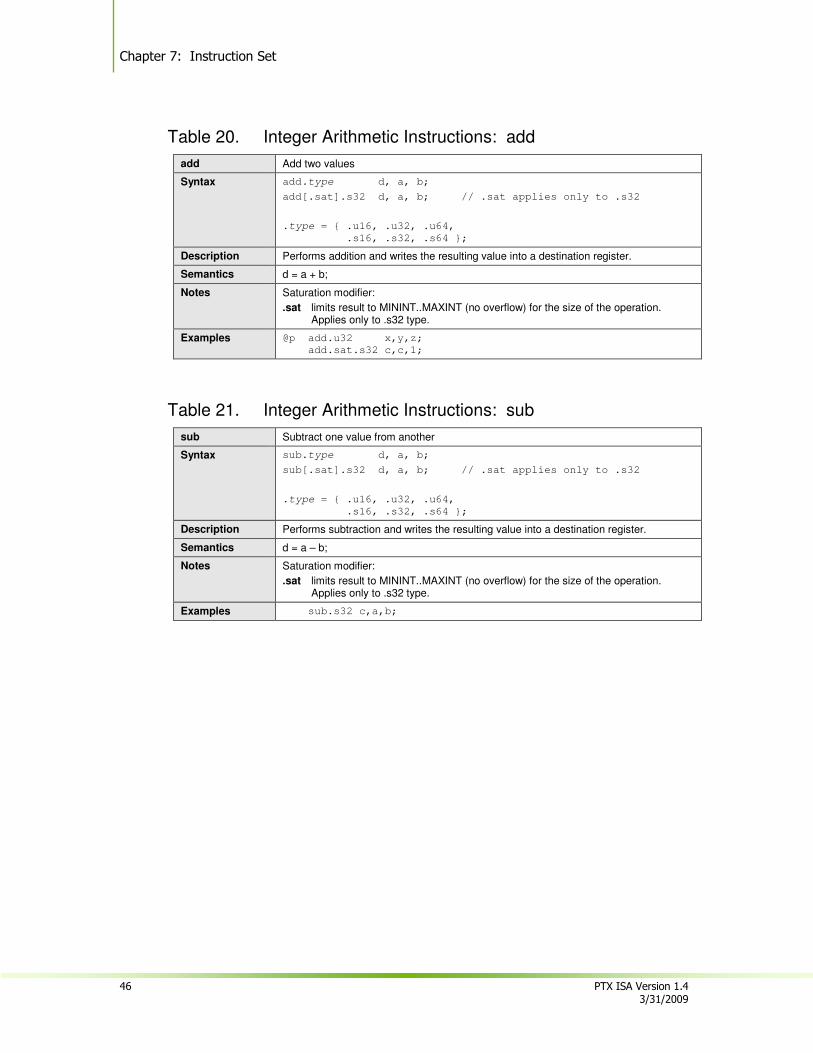
Chapter 7: Instruction Set
46 PTX ISA Version 1.4 3/31/2009
Table 20. Integer Arithmetic Instructions: add
add Add two values
Syntax add.type d, a, b;
add[.sat].s32 d, a, b; // .sat applies only to .s32
.type = { .u16, .u32, .u64,
.s16, .s32, .s64 };
Description Performs addition and writes the resulting value into a destination register.
Semantics d = a + b;
Notes Saturation modifier:
.sat limits result to MININT..MAXINT (no overflow) for the size of the operation. Applies only to .s32 type.
Examples @p add.u32 x,y,z;
add.sat.s32 c,c,1;
Table 21. Integer Arithmetic Instructions: sub
sub Subtract one value from another
Syntax sub.type d, a, b;
sub[.sat].s32 d, a, b; // .sat applies only to .s32
.type = { .u16, .u32, .u64,
.s16, .s32, .s64 };
Description Performs subtraction and writes the resulting value into a destination register.
Semantics d = a – b;
Notes Saturation modifier:
.sat limits result to MININT..MAXINT (no overflow) for the size of the operation. Applies only to .s32 type.
Examples sub.s32 c,a,b;

Chapter 7. Instruction Set
PTX ISA Version 1.4 47 3/31/2009
Instructions add, addc, sub and subc, reference an implicitly specified condition code register (CC) having a single carry flag bit (CC.CF) holding carry-in/carry-out or borrow-in/borrow-out. These instructions support extended-precision integer addition and subtraction. No other instructions access the condition code, and there is no support for setting, clearing, or testing the condition code.
Table 22. Integer Arithmetic Instructions: add
add Add two values with optional carry-out
Syntax add[.cc].type d, a, b;
.type = { .u32, .s32 };
Description Performs 32-bit integer addition and optionally writes the carry-out value into the condition code register.
Semantics d = a + b;
if .cc specified, carry-out written to CC.CF
Notes No integer rounding modifiers.
No saturation.
Behavior is the same for unsigned and signed integers.
Examples @p add.cc.b32 x1,y1,z1; // extended-precision addition of
@p addc.cc.b32 x2,y2,z2; // two 128-bit values
@p addc.cc.b32 x3,y3,z3;
@p addc.cc.b32 x4,y4,z4;
Table 23. Integer Arithmetic Instructions: addc
addc Add two values with carry-in and optional carry-out
Syntax addc[.cc].type d, a, b;
.type = {.u32, .s32 };
Description Performs 32-bit integer addition with carry-in and optionally writes the carry-out value into the condition code register.
Semantics d = a + b + CC.CF;
if .cc specified, carry-out written to CC.CF
Notes No integer rounding modifiers.
No saturation.
Behavior is the same for unsigned and signed integers.
Examples @p add.cc.b32 x1,y1,z1; // extended-precision addition of
@p addc.cc.b32 x2,y2,z2; // two 128-bit values
@p addc.cc.b32 x3,y3,z3;
@p addc.cc.b32 x4,y4,z4;
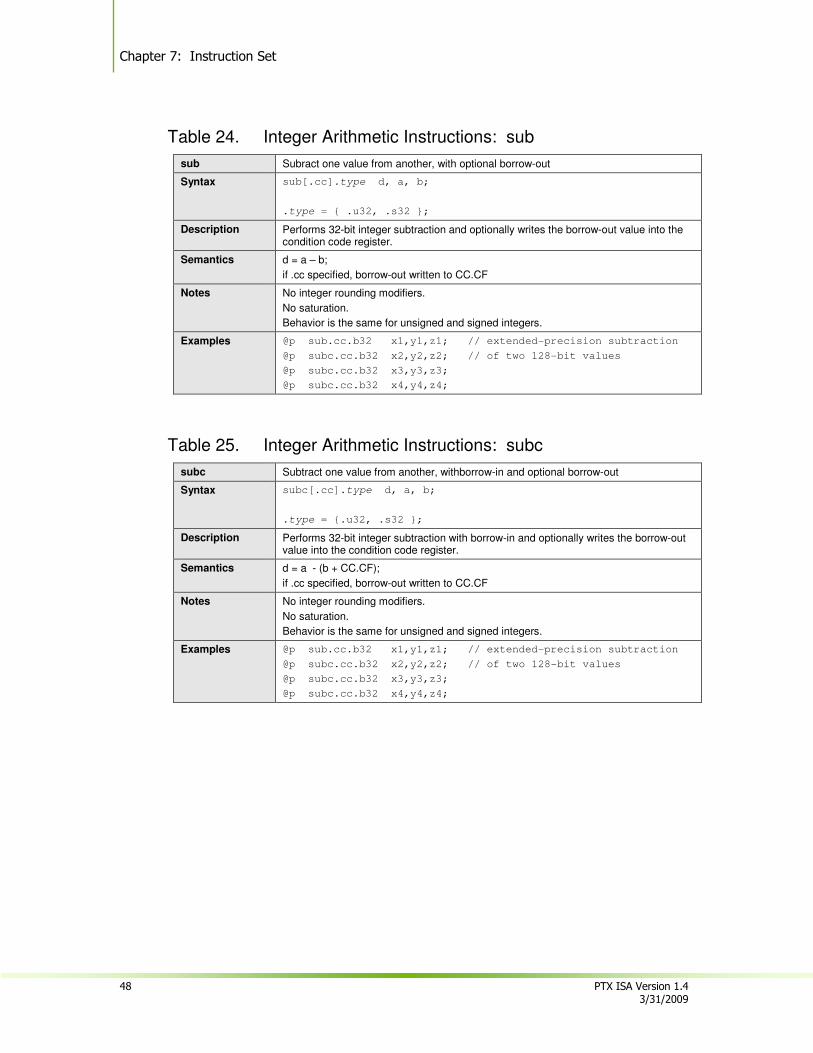
Chapter 7: Instruction Set
48 PTX ISA Version 1.4 3/31/2009
Table 24. Integer Arithmetic Instructions: sub
sub Subract one value from another, with optional borrow-out
Syntax sub[.cc].type d, a, b;
.type = { .u32, .s32 };
Description Performs 32-bit integer subtraction and optionally writes the borrow-out value into the condition code register.
Semantics d = a – b;
if .cc specified, borrow-out written to CC.CF
Notes No integer rounding modifiers.
No saturation.
Behavior is the same for unsigned and signed integers.
Examples @p sub.cc.b32 x1,y1,z1; // extended-precision subtraction
@p subc.cc.b32 x2,y2,z2; // of two 128-bit values
@p subc.cc.b32 x3,y3,z3;
@p subc.cc.b32 x4,y4,z4;
Table 25. Integer Arithmetic Instructions: subc
subc Subtract one value from another, withborrow-in and optional borrow-out
Syntax subc[.cc].type d, a, b;
.type = {.u32, .s32 };
Description Performs 32-bit integer subtraction with borrow-in and optionally writes the borrow-out value into the condition code register.
Semantics d = a - (b + CC.CF);
if .cc specified, borrow-out written to CC.CF
Notes No integer rounding modifiers.
No saturation.
Behavior is the same for unsigned and signed integers.
Examples @p sub.cc.b32 x1,y1,z1; // extended-precision subtraction
@p subc.cc.b32 x2,y2,z2; // of two 128-bit values
@p subc.cc.b32 x3,y3,z3;
@p subc.cc.b32 x4,y4,z4;
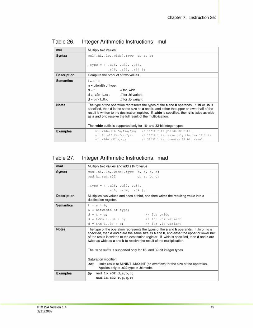
Chapter 7. Instruction Set
PTX ISA Version 1.4 49 3/31/2009
Table 26. Integer Arithmetic Instructions: mul
mul Multiply two values
Syntax mul[.hi,.lo,.wide].type d, a, b;
.type = { .u16, .u32, .u64,
.s16, .s32, .s64 };
Description Compute the product of two values.
Semantics t = a * b;
n = bitwidth of type;
d = t; // for .wide
d = t<2n-1..n>; // for .hi variant
d = t<n-1..0>; // for .lo variant
Notes The type of the operation represents the types of the a and b operands. If .hi or .lo is specified, then d is the same size as a and b, and either the upper or lower half of the result is written to the destination register. If .wide is specified, then d is twice as wide as a and b to receive the full result of the multiplication.
The .wide suffix is supported only for 16- and 32-bit integer types.
Examples mul.wide.s16 fa,fxs,fys; // 16*16 bits yields 32 bits
mul.lo.s16 fa,fxs,fys; // 16*16 bits, save only the low 16 bits
mul.wide.s32 z,x,y; // 32*32 bits, creates 64 bit result
Table 27. Integer Arithmetic Instructions: mad
mad Multiply two values and add a third value
Syntax mad[.hi,.lo,.wide].type d, a, b, c;
mad.hi.sat.s32 d, a, b, c;
.type = { .u16, .u32, .u64,
.s16, .s32, .s64 };
Description Multiplies two values and adds a third, and then writes the resulting value into a destination register.
Semantics t = a * b;
n = bitwidth of type;
d = t + c; // for .wide
d = t<2n-1..n> + c; // for .hi variant
d = t<n-1..0> + c; // for .lo variant
Notes The type of the operation represents the types of the a and b operands. If .hi or .lo is specified, then d and c are the same size as a and b, and either the upper or lower half of the result is written to the destination register. If .wide is specified, then d and c are twice as wide as a and b to receive the result of the multiplication.
The .wide suffix is supported only for 16- and 32-bit integer types.
Saturation modifier:
.sat limits result to MININT..MAXINT (no overflow) for the size of the operation. Applies only to .s32 type in .hi mode.
Examples @p mad.lo.s32 d,a,b,c;
mad.lo.s32 r,p,q,r;
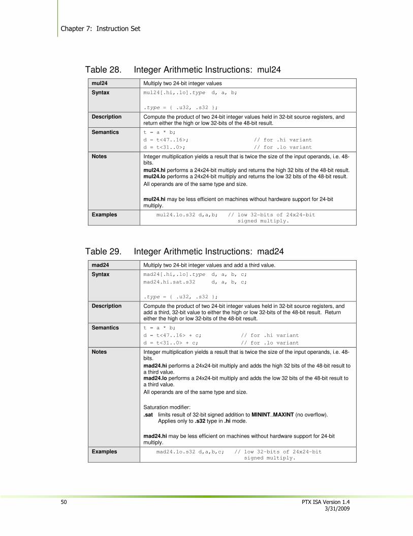
Chapter 7: Instruction Set
50 PTX ISA Version 1.4 3/31/2009
Table 28. Integer Arithmetic Instructions: mul24
mul24 Multiply two 24-bit integer values
Syntax mul24[.hi,.lo].type d, a, b;
.type = { .u32, .s32 };
Description Compute the product of two 24-bit integer values held in 32-bit source registers, and return either the high or low 32-bits of the 48-bit result.
Semantics t = a * b;
d = t<47..16>; // for .hi variant
d = t<31..0>; // for .lo variant
Notes Integer multiplication yields a result that is twice the size of the input operands, i.e. 48-bits.
mul24.hi performs a 24x24-bit multiply and returns the high 32 bits of the 48-bit result. mul24.lo performs a 24x24-bit multiply and returns the low 32 bits of the 48-bit result.
All operands are of the same type and size.
mul24.hi may be less efficient on machines without hardware support for 24-bit multiply.
Examples mul24.lo.s32 d,a,b; // low 32-bits of 24x24-bit
signed multiply.
Table 29. Integer Arithmetic Instructions: mad24
mad24 Multiply two 24-bit integer values and add a third value.
Syntax mad24[.hi,.lo].type d, a, b, c;
mad24.hi.sat.s32 d, a, b, c;
.type = { .u32, .s32 };
Description Compute the product of two 24-bit integer values held in 32-bit source registers, and add a third, 32-bit value to either the high or low 32-bits of the 48-bit result. Return either the high or low 32-bits of the 48-bit result.
Semantics t = a * b;
d = t<47..16> + c; // for .hi variant
d = t<31..0> + c; // for .lo variant
Notes Integer multiplication yields a result that is twice the size of the input operands, i.e. 48-bits.
mad24.hi performs a 24x24-bit multiply and adds the high 32 bits of the 48-bit result to a third value. mad24.lo performs a 24x24-bit multiply and adds the low 32 bits of the 48-bit result to a third value.
All operands are of the same type and size.
Saturation modifier:
.sat limits result of 32-bit signed addition to MININT..MAXINT (no overflow). Applies only to .s32 type in .hi mode.
mad24.hi may be less efficient on machines without hardware support for 24-bit multiply.
Examples mad24.lo.s32 d,a,b,c; // low 32-bits of 24x24-bit
signed multiply.
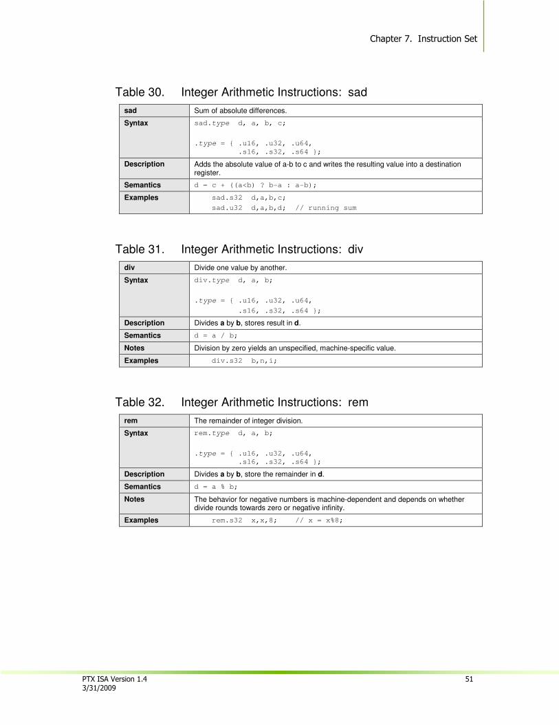
Chapter 7. Instruction Set
PTX ISA Version 1.4 51 3/31/2009
Table 30. Integer Arithmetic Instructions: sad
sad Sum of absolute differences.
Syntax sad.type d, a, b, c;
.type = { .u16, .u32, .u64,
.s16, .s32, .s64 };
Description Adds the absolute value of a-b to c and writes the resulting value into a destination register.
Semantics d = c + ((a<b) ? b-a : a-b);
Examples sad.s32 d,a,b,c;
sad.u32 d,a,b,d; // running sum
Table 31. Integer Arithmetic Instructions: div
div Divide one value by another.
Syntax div.type d, a, b;
.type = { .u16, .u32, .u64,
.s16, .s32, .s64 };
Description Divides a by b, stores result in d.
Semantics d = a / b;
Notes Division by zero yields an unspecified, machine-specific value.
Examples div.s32 b,n,i;
Table 32. Integer Arithmetic Instructions: rem
rem The remainder of integer division.
Syntax rem.type d, a, b;
.type = { .u16, .u32, .u64,
.s16, .s32, .s64 };
Description Divides a by b, store the remainder in d.
Semantics d = a % b;
Notes The behavior for negative numbers is machine-dependent and depends on whether divide rounds towards zero or negative infinity.
Examples rem.s32 x,x,8; // x = x%8;
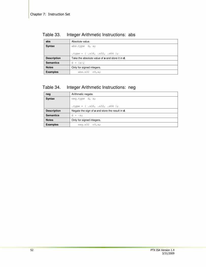
Chapter 7: Instruction Set
52 PTX ISA Version 1.4 3/31/2009
Table 33. Integer Arithmetic Instructions: abs
abs Absolute value.
Syntax abs.type d, a;
.type = { .s16, .s32, .s64 };
Description Take the absolute value of a and store it in d.
Semantics d = |a|;
Notes Only for signed integers.
Examples abs.s32 r0,a;
Table 34. Integer Arithmetic Instructions: neg
neg Arithmetic negate.
Syntax neg.type d, a;
.type = { .s16, .s32, .s64 };
Description Negate the sign of a and store the result in d.
Semantics d = -a;
Notes Only for signed integers.
Examples neg.s32 r0,a;
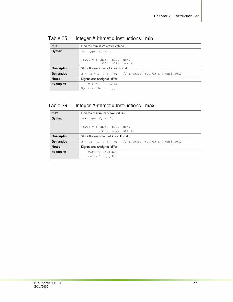
Chapter 7. Instruction Set
PTX ISA Version 1.4 53 3/31/2009
Table 35. Integer Arithmetic Instructions: min
min Find the minimum of two values.
Syntax min.type d, a, b;
.type = { .u16, .u32, .u64,
.s16, .s32, .s64 };
Description Store the minimum of a and b in d.
Semantics d = (a < b) ? a : b; // Integer (signed and unsigned)
Notes Signed and unsigned differ.
Examples min.s32 r0,a,b;
@p min.u16 h,i,j;
Table 36. Integer Arithmetic Instructions: max
max Find the maximum of two values.
Syntax max.type d, a, b;
.type = { .u16, .u32, .u64,
.s16, .s32, .s64 };
Description Store the maximum of a and b in d.
Semantics d = (a > b) ? a : b; // Integer (signed and unsigned)
Notes Signed and unsigned differ.
Examples max.u32 d,a,b;
max.s32 q,q,0;
Chapter 7: Instruction Set
54 PTX ISA Version 1.4 3/31/2009
7.7.2. Floating-Point Instructions
Floating-point instructions operate on .f32 and .f64 register operands and constant immediate values. The floating-point instructions are:
� add
� sub
� mul
� fma
� mad
� div
� abs
� neg
� min
� max
� rcp
� sqrt
� rsqrt
� sin
� cos
� lg2
� ex2
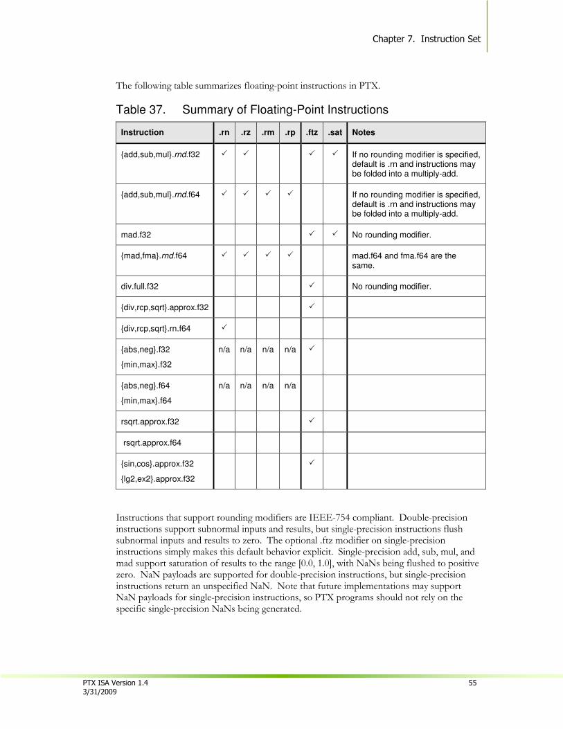
Chapter 7. Instruction Set
PTX ISA Version 1.4 55 3/31/2009
The following table summarizes floating-point instructions in PTX.
Table 37. Summary of Floating-Point Instructions
Instruction .rn .rz .rm .rp .ftz .sat Notes
{add,sub,mul}.rnd.f32 � � � � If no rounding modifier is specified, default is .rn and instructions may be folded into a multiply-add.
{add,sub,mul}.rnd.f64 � � � � If no rounding modifier is specified, default is .rn and instructions may be folded into a multiply-add.
mad.f32 � � No rounding modifier.
{mad,fma}.rnd.f64 � � � � mad.f64 and fma.f64 are the same.
div.full.f32 � No rounding modifier.
{div,rcp,sqrt}.approx.f32 �
{div,rcp,sqrt}.rn.f64 �
{abs,neg}.f32
{min,max}.f32
n/a n/a n/a n/a �
{abs,neg}.f64
{min,max}.f64
n/a n/a n/a n/a
rsqrt.approx.f32 �
rsqrt.approx.f64
{sin,cos}.approx.f32
{lg2,ex2}.approx.f32
�
Instructions that support rounding modifiers are IEEE-754 compliant. Double-precision instructions support subnormal inputs and results, but single-precision instructions flush subnormal inputs and results to zero. The optional .ftz modifier on single-precision instructions simply makes this default behavior explicit. Single-precision add, sub, mul, and mad support saturation of results to the range [0.0, 1.0], with NaNs being flushed to positive zero. NaN payloads are supported for double-precision instructions, but single-precision instructions return an unspecified NaN. Note that future implementations may support NaN payloads for single-precision instructions, so PTX programs should not rely on the specific single-precision NaNs being generated.
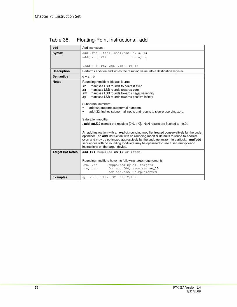
Chapter 7: Instruction Set
56 PTX ISA Version 1.4 3/31/2009
Table 38. Floating-Point Instructions: add
add Add two values
Syntax add[.rnd][.ftz][.sat].f32 d, a, b;
add[.rnd].f64 d, a, b;
.rnd = { .rn, .rz, .rm, .rp };
Description Performs addition and writes the resulting value into a destination register.
Semantics d = a + b;
Notes Rounding modifiers (default is .rn):
.rn mantissa LSB rounds to nearest even
.rz mantissa LSB rounds towards zero
.rm mantissa LSB rounds towards negative infinity
.rp mantissa LSB rounds towards positive infinity Subnormal numbers:
• add.f64 supports subnormal numbers.
• add.f32 flushes subnormal inputs and results to sign-preserving zero.
Saturation modifier:
. add.sat.f32 clamps the result to [0.0, 1.0]. NaN results are flushed to +0.0f.
An add instruction with an explicit rounding modifier treated conservatively by the code optimizer. An add instruction with no rounding modifier defaults to round-to-nearest-even and may be optimized aggressively by the code optimizer. In particular, mul/add sequences with no rounding modifiers may be optimized to use fused-multiply-add instructions on the target device.
Target ISA Notes add.f64 requires sm_13 or later.
Rounding modifiers have the following target requirements:
.rn, .rz supported by all targets
.rm, .rp for add.f64, requires sm_13
for add.f32, unimplemented
Examples @p add.rz.ftz.f32 f1,f2,f3;
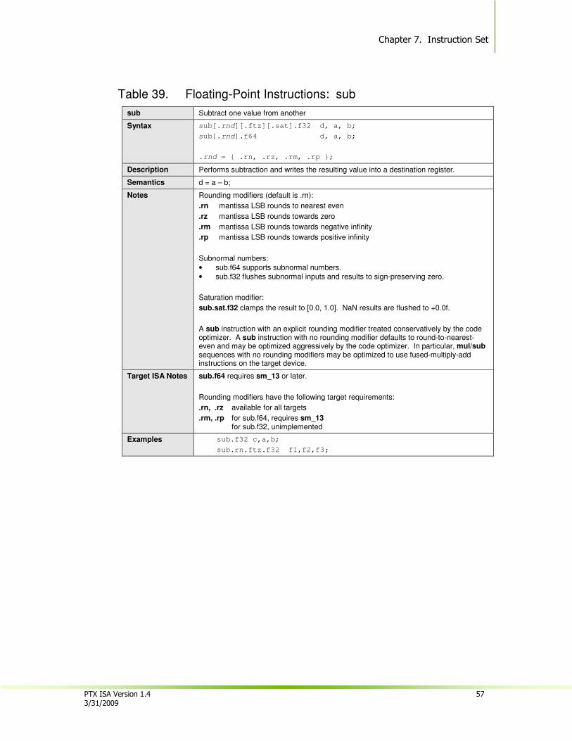
Chapter 7. Instruction Set
PTX ISA Version 1.4 57 3/31/2009
Table 39. Floating-Point Instructions: sub
sub Subtract one value from another
Syntax sub[.rnd][.ftz][.sat].f32 d, a, b;
sub[.rnd].f64 d, a, b;
.rnd = { .rn, .rz, .rm, .rp };
Description Performs subtraction and writes the resulting value into a destination register.
Semantics d = a – b;
Notes Rounding modifiers (default is .rn):
.rn mantissa LSB rounds to nearest even
.rz mantissa LSB rounds towards zero
.rm mantissa LSB rounds towards negative infinity
.rp mantissa LSB rounds towards positive infinity
Subnormal numbers:
• sub.f64 supports subnormal numbers.
• sub.f32 flushes subnormal inputs and results to sign-preserving zero.
Saturation modifier:
sub.sat.f32 clamps the result to [0.0, 1.0]. NaN results are flushed to +0.0f.
A sub instruction with an explicit rounding modifier treated conservatively by the code optimizer. A sub instruction with no rounding modifier defaults to round-to-nearest-even and may be optimized aggressively by the code optimizer. In particular, mul/sub sequences with no rounding modifiers may be optimized to use fused-multiply-add instructions on the target device.
Target ISA Notes sub.f64 requires sm_13 or later.
Rounding modifiers have the following target requirements:
.rn, .rz available for all targets
.rm, .rp for sub.f64, requires sm_13 for sub.f32, unimplemented
Examples sub.f32 c,a,b;
sub.rn.ftz.f32 f1,f2,f3;
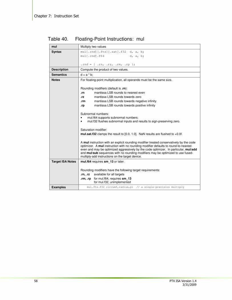
Chapter 7: Instruction Set
58 PTX ISA Version 1.4 3/31/2009
Table 40. Floating-Point Instructions: mul
mul Multiply two values
Syntax mul[.rnd][.ftz][.sat].f32 d, a, b;
mul[.rnd].f64 d, a, b;
.rnd = { .rn, .rz, .rm, .rp };
Description Compute the product of two values.
Semantics d = a * b;
Notes For floating-point multiplication, all operands must be the same size.
Rounding modifiers (default is .rn):
.rn mantissa LSB rounds to nearest even
.rz mantissa LSB rounds towards zero
.rm mantissa LSB rounds towards negative infinity
.rp mantissa LSB rounds towards positive infinity
Subnormal numbers:
• mul.f64 supports subnormal numbers.
• mul.f32 flushes subnormal inputs and results to sign-preserving zero.
Saturation modifier:
mul.sat.f32 clamps the result to [0.0, 1.0]. NaN results are flushed to +0.0f.
A mul instruction with an explicit rounding modifier treated conservatively by the code optimizer. A mul instruction with no rounding modifier defaults to round-to-nearest-even and may be optimized aggressively by the code optimizer. In particular, mul/add and mul/sub sequences with no rounding modifiers may be optimized to use fused-multiply-add instructions on the target device.
Target ISA Notes mul.f64 requires sm_13 or later.
Rounding modifiers have the following target requirements:
.rn, .rz available for all targets
.rm, .rp for mul.f64, requires sm_13 for mul.f32, unimplemented
Examples mul.ftz.f32 circumf,radius,pi // a single-precision multiply
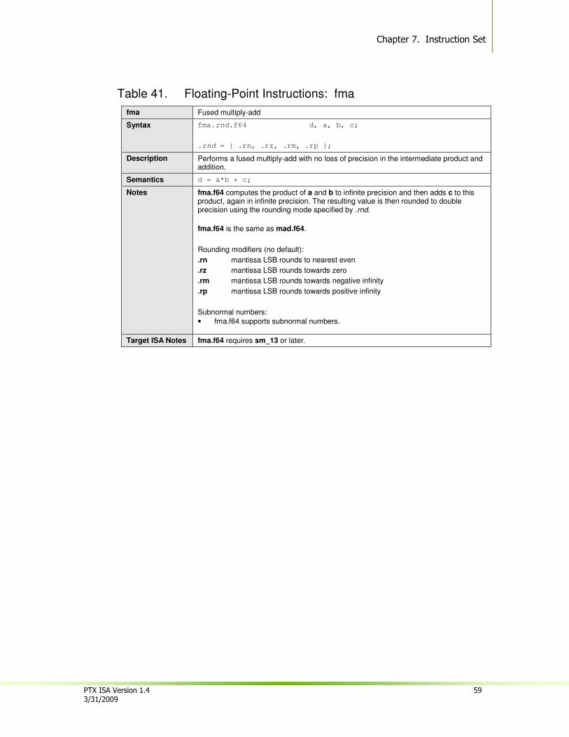
Chapter 7. Instruction Set
PTX ISA Version 1.4 59 3/31/2009
Table 41. Floating-Point Instructions: fma
fma Fused multiply-add
Syntax fma.rnd.f64 d, a, b, c;
.rnd = { .rn, .rz, .rm, .rp };
Description Performs a fused multiply-add with no loss of precision in the intermediate product and addition.
Semantics d = a*b + c;
Notes fma.f64 computes the product of a and b to infinite precision and then adds c to this product, again in infinite precision. The resulting value is then rounded to double precision using the rounding mode specified by .rnd.
fma.f64 is the same as mad.f64.
Rounding modifiers (no default):
.rn mantissa LSB rounds to nearest even
.rz mantissa LSB rounds towards zero
.rm mantissa LSB rounds towards negative infinity
.rp mantissa LSB rounds towards positive infinity
Subnormal numbers:
• fma.f64 supports subnormal numbers.
Target ISA Notes fma.f64 requires sm_13 or later.
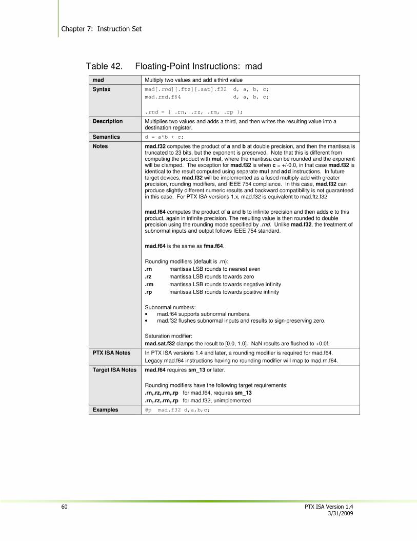
Chapter 7: Instruction Set
60 PTX ISA Version 1.4 3/31/2009
Table 42. Floating-Point Instructions: mad
mad Multiply two values and add a third value
Syntax mad[.rnd][.ftz][.sat].f32 d, a, b, c;
mad.rnd.f64 d, a, b, c;
.rnd = { .rn, .rz, .rm, .rp };
Description Multiplies two values and adds a third, and then writes the resulting value into a destination register.
Semantics d = a*b + c;
Notes mad.f32 computes the product of a and b at double precision, and then the mantissa is truncated to 23 bits, but the exponent is preserved. Note that this is different from computing the product with mul, where the mantissa can be rounded and the exponent will be clamped. The exception for mad.f32 is when c = +/-0.0, in that case mad.f32 is identical to the result computed using separate mul and add instructions. In future target devices, mad.f32 will be implemented as a fused multiply-add with greater precision, rounding modifiers, and IEEE 754 compliance. In this case, mad.f32 can produce slightly different numeric results and backward compatibility is not guaranteed in this case. For PTX ISA versions 1.x, mad.f32 is equivalent to mad.ftz.f32
mad.f64 computes the product of a and b to infinite precision and then adds c to this product, again in infinite precision. The resulting value is then rounded to double precision using the rounding mode specified by .rnd. Unlike mad.f32, the treatment of subnormal inputs and output follows IEEE 754 standard.
mad.f64 is the same as fma.f64.
Rounding modifiers (default is .rn):
.rn mantissa LSB rounds to nearest even
.rz mantissa LSB rounds towards zero
.rm mantissa LSB rounds towards negative infinity
.rp mantissa LSB rounds towards positive infinity
Subnormal numbers:
• mad.f64 supports subnormal numbers.
• mad.f32 flushes subnormal inputs and results to sign-preserving zero.
Saturation modifier:
mad.sat.f32 clamps the result to [0.0, 1.0]. NaN results are flushed to +0.0f.
PTX ISA Notes In PTX ISA versions 1.4 and later, a rounding modifier is required for mad.f64.
Legacy mad.f64 instructions having no rounding modifier will map to mad.rn.f64.
Target ISA Notes mad.f64 requires sm_13 or later.
Rounding modifiers have the following target requirements:
.rn,.rz,.rm,.rp for mad.f64, requires sm_13
.rn,.rz,.rm,.rp for mad.f32, unimplemented
Examples @p mad.f32 d,a,b,c;
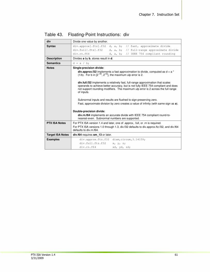
Chapter 7. Instruction Set
PTX ISA Version 1.4 61 3/31/2009
Table 43. Floating-Point Instructions: div
div Divide one value by another.
Syntax div.approx[.ftz].f32 d, a, b; // fast, approximate divide
div.full[.ftz].f32 d, a, b; // full-range approximate divide
div.rn.f64 d, a, b; // IEEE 754 compliant rounding
Description Divides a by b, stores result in d.
Semantics d = a / b;
Notes Single-precision divide:
div.approx.f32 implements a fast approximation to divide, computed as d = a * (1/b). For b in [2
-126, 2
126], the maximum ulp error is 2.
div.full.f32 implements a relatively fast, full-range approximation that scales operands to achieve better accuracy, but is not fully IEEE 754 compliant and does not support rounding modifiers. The maximum ulp error is 2 across the full range of inputs.
Subnormal inputs and results are flushed to sign-preserving zero.
Fast, approximate division by zero creates a value of infinity (with same sign as a).
Double-precision divide:
div.rn.f64 implements an accurate divide with IEEE 754 compliant round-to-nearest-even. Subnormal numbers are supported.
PTX ISA Notes For PTX ISA version 1.4 and later, one of .approx, .full, or .rn is required.
For PTX ISA versions 1.0 through 1.3, div.f32 defaults to div.approx.ftz.f32, and div.f64 defaults to div.rn.f64.
Target ISA Notes div.f64 requires sm_13 or later.
Examples div.approx.ftz.f32 diam,circum,3.14159;
div.full.ftz.f32 x, y, z;
div.rn.f64 xd, yd, zd;
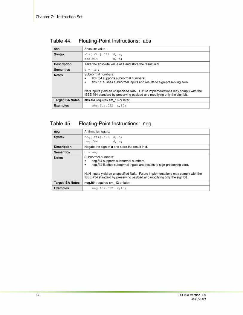
Chapter 7: Instruction Set
62 PTX ISA Version 1.4 3/31/2009
Table 44. Floating-Point Instructions: abs
abs Absolute value.
Syntax abs[.ftz].f32 d, a;
abs.f64 d, a;
Description Take the absolute value of a and store the result in d.
Semantics d = |a|;
Notes Subnormal numbers:
• abs.f64 supports subnormal numbers.
• abs.f32 flushes subnormal inputs and results to sign-preserving zero.
NaN inputs yield an unspecified NaN. Future implementations may comply with the IEEE 754 standard by preserving payload and modifying only the sign bit.
Target ISA Notes abs.f64 requires sm_13 or later.
Examples abs.ftz.f32 x,f0;
Table 45. Floating-Point Instructions: neg
neg Arithmetic negate.
Syntax neg[.ftz].f32 d, a;
neg.f64 d, a;
Description Negate the sign of a and store the result in d.
Semantics d = -a;
Notes Subnormal numbers:
• neg.f64 supports subnormal numbers.
• neg.f32 flushes subnormal inputs and results to sign-preserving zero.
NaN inputs yield an unspecified NaN. Future implementations may comply with the IEEE 754 standard by preserving payload and modifying only the sign bit.
Target ISA Notes neg.f64 requires sm_13 or later.
Examples neg.ftz.f32 x,f0;
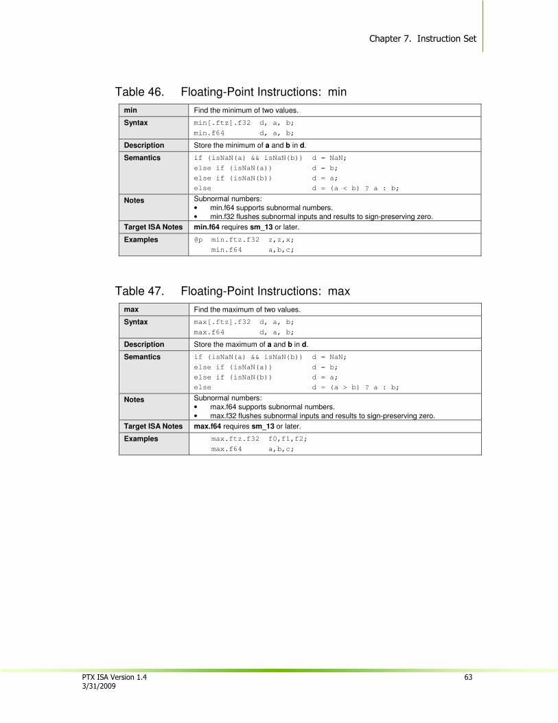
Chapter 7. Instruction Set
PTX ISA Version 1.4 63 3/31/2009
Table 46. Floating-Point Instructions: min
min Find the minimum of two values.
Syntax min[.ftz].f32 d, a, b;
min.f64 d, a, b;
Description Store the minimum of a and b in d.
Semantics if (isNaN(a) && isNaN(b)) d = NaN;
else if (isNaN(a)) d = b;
else if (isNaN(b)) d = a;
else d = (a < b) ? a : b;
Notes Subnormal numbers:
• min.f64 supports subnormal numbers.
• min.f32 flushes subnormal inputs and results to sign-preserving zero.
Target ISA Notes min.f64 requires sm_13 or later.
Examples @p min.ftz.f32 z,z,x;
min.f64 a,b,c;
Table 47. Floating-Point Instructions: max
max Find the maximum of two values.
Syntax max[.ftz].f32 d, a, b;
max.f64 d, a, b;
Description Store the maximum of a and b in d.
Semantics if (isNaN(a) && isNaN(b)) d = NaN;
else if (isNaN(a)) d = b;
else if (isNaN(b)) d = a;
else d = (a > b) ? a : b;
Notes Subnormal numbers:
• max.f64 supports subnormal numbers.
• max.f32 flushes subnormal inputs and results to sign-preserving zero.
Target ISA Notes max.f64 requires sm_13 or later.
Examples max.ftz.f32 f0,f1,f2;
max.f64 a,b,c;
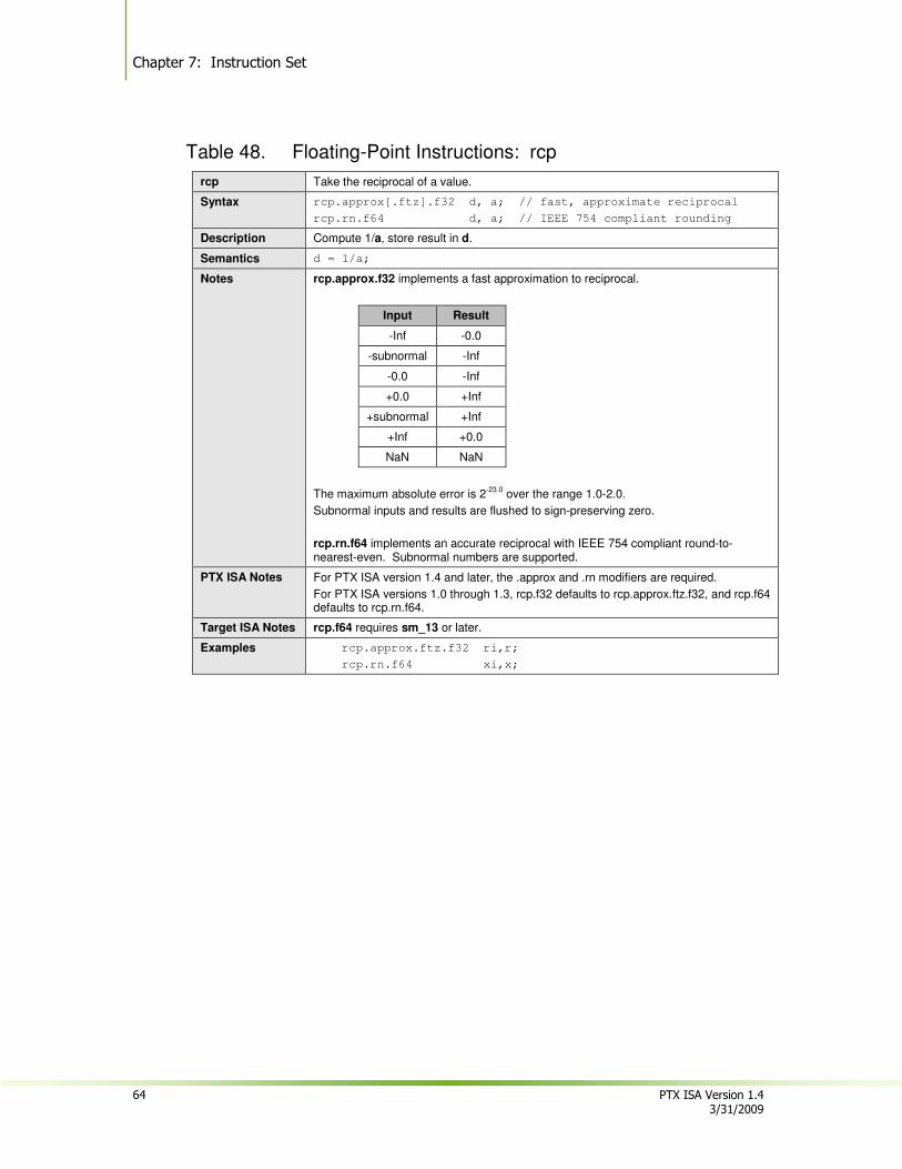
Chapter 7: Instruction Set
64 PTX ISA Version 1.4 3/31/2009
Table 48. Floating-Point Instructions: rcp
rcp Take the reciprocal of a value.
Syntax rcp.approx[.ftz].f32 d, a; // fast, approximate reciprocal
rcp.rn.f64 d, a; // IEEE 754 compliant rounding
Description Compute 1/a, store result in d.
Semantics d = 1/a;
Notes rcp.approx.f32 implements a fast approximation to reciprocal.
Input Result
-Inf -0.0
-subnormal -Inf
-0.0 -Inf
+0.0 +Inf
+subnormal +Inf
+Inf +0.0
NaN NaN
The maximum absolute error is 2-23.0
over the range 1.0-2.0.
Subnormal inputs and results are flushed to sign-preserving zero.
rcp.rn.f64 implements an accurate reciprocal with IEEE 754 compliant round-to-nearest-even. Subnormal numbers are supported.
PTX ISA Notes For PTX ISA version 1.4 and later, the .approx and .rn modifiers are required.
For PTX ISA versions 1.0 through 1.3, rcp.f32 defaults to rcp.approx.ftz.f32, and rcp.f64 defaults to rcp.rn.f64.
Target ISA Notes rcp.f64 requires sm_13 or later.
Examples rcp.approx.ftz.f32 ri,r;
rcp.rn.f64 xi,x;

Chapter 7. Instruction Set
PTX ISA Version 1.4 65 3/31/2009
Table 49. Floating-Point Instructions: sqrt
sqrt Take the square root of a value.
Syntax sqrt.approx[.ftz].f32 d, a; // fast, approximate square root
sqrt.rn.f64 d, a; // IEEE 754 compliant rounding
Description Compute sqrt(a); store in d.
Semantics d = sqrt(a);
Notes sqrt.approx.f32 implements a fast approximation to square root.
Input Result
-Inf NaN
-normal NaN
-subnormal -0.0
-0.0 -0.0
+0.0 +0.0
+subnormal +0.0
+Inf +Inf
NaN NaN
The maximum absolute error for sqrt.f32 is TBD.
Subnormal inputs and results are flushed to sign-preserving zero.
sqrt.f64 implements an accurate reciprocal with IEEE 754 compliant round-to-nearest-even. Subnormal numbers are supported.
PTX ISA Notes For PTX ISA version 1.4 and later, the .approx and .rn modifiers are required.
For PTX ISA versions 1.0 through 1.3, sqrt.f32 defaults to sqrt.approx.ftz.f32, and sqrt.f64 defaults to sqrt.rn.f64.
Target ISA Notes sqrt.f64 requires sm_13 or later.
Examples sqrt.approx.ftz.f32 r,x;
sqrt.rn.f64 r,x;
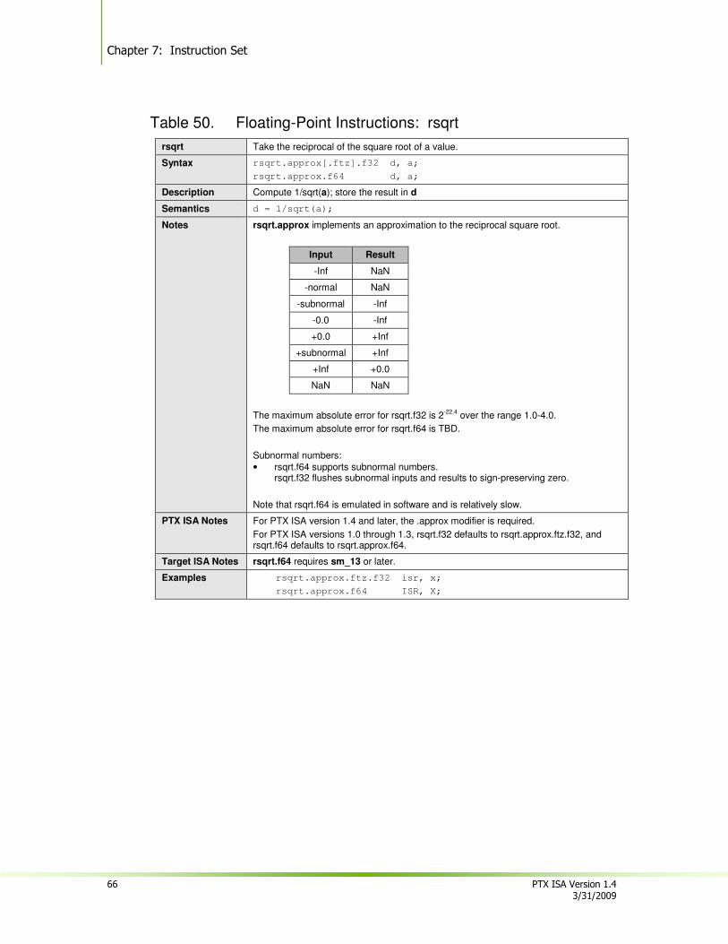
Chapter 7: Instruction Set
66 PTX ISA Version 1.4 3/31/2009
Table 50. Floating-Point Instructions: rsqrt
rsqrt Take the reciprocal of the square root of a value.
Syntax rsqrt.approx[.ftz].f32 d, a;
rsqrt.approx.f64 d, a;
Description Compute 1/sqrt(a); store the result in d
Semantics d = 1/sqrt(a);
Notes rsqrt.approx implements an approximation to the reciprocal square root.
Input Result
-Inf NaN
-normal NaN
-subnormal -Inf
-0.0 -Inf
+0.0 +Inf
+subnormal +Inf
+Inf +0.0
NaN NaN
The maximum absolute error for rsqrt.f32 is 2-22.4
over the range 1.0-4.0.
The maximum absolute error for rsqrt.f64 is TBD.
Subnormal numbers:
• rsqrt.f64 supports subnormal numbers. rsqrt.f32 flushes subnormal inputs and results to sign-preserving zero.
Note that rsqrt.f64 is emulated in software and is relatively slow.
PTX ISA Notes For PTX ISA version 1.4 and later, the .approx modifier is required.
For PTX ISA versions 1.0 through 1.3, rsqrt.f32 defaults to rsqrt.approx.ftz.f32, and rsqrt.f64 defaults to rsqrt.approx.f64.
Target ISA Notes rsqrt.f64 requires sm_13 or later.
Examples rsqrt.approx.ftz.f32 isr, x;
rsqrt.approx.f64 ISR, X;
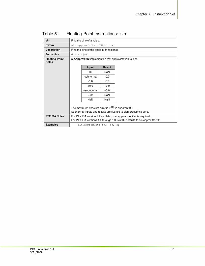
Chapter 7. Instruction Set
PTX ISA Version 1.4 67 3/31/2009
Table 51. Floating-Point Instructions: sin
sin Find the sine of a value.
Syntax sin.approx[.ftz].f32 d, a;
Description Find the sine of the angle a (in radians).
Semantics d = sin(a);
Floating-Point Notes
sin.approx.f32 implements a fast approximation to sine.
Input Result
-Inf NaN
-subnormal -0.0
-0.0 -0.0
+0.0 +0.0
+subnormal +0.0
+Inf NaN
NaN NaN
The maximum absolute error is 2-20.9
in quadrant 00.
Subnormal inputs and results are flushed to sign-preserving zero.
PTX ISA Notes For PTX ISA version 1.4 and later, the .approx modifier is required.
For PTX ISA versions 1.0 through 1.3, sin.f32 defaults to sin.approx.ftz.f32.
Examples sin.approx.ftz.f32 sa, a;
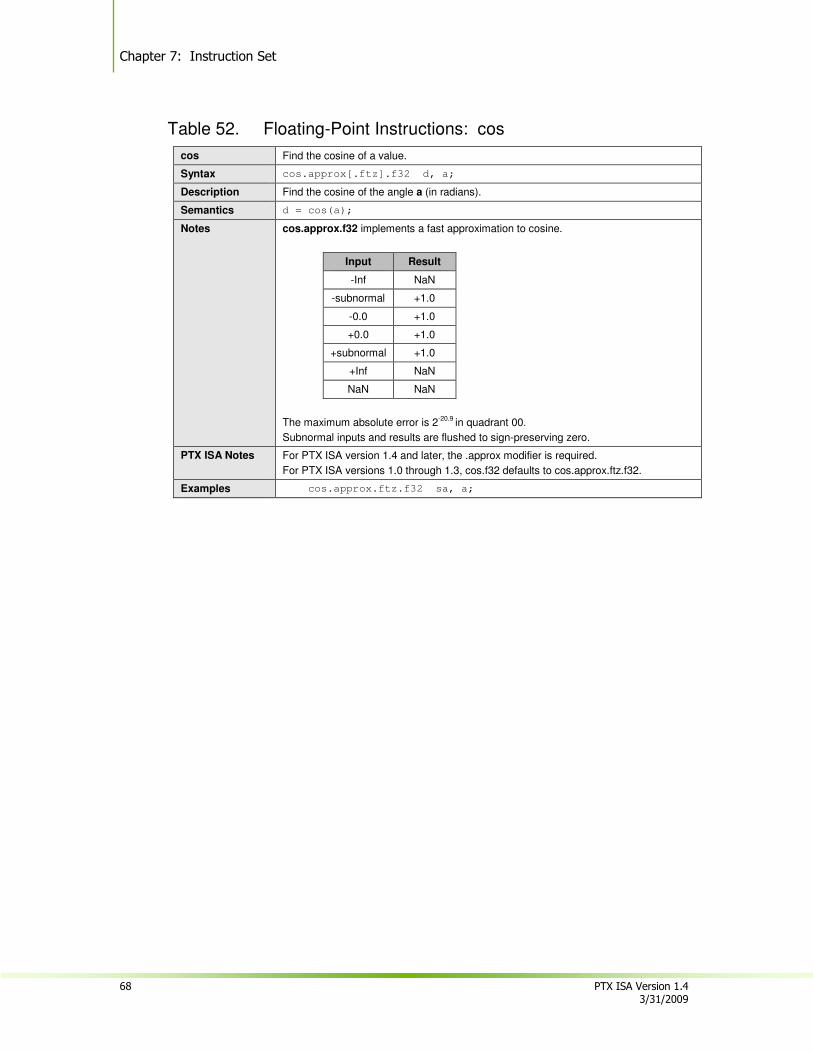
Chapter 7: Instruction Set
68 PTX ISA Version 1.4 3/31/2009
Table 52. Floating-Point Instructions: cos
cos Find the cosine of a value.
Syntax cos.approx[.ftz].f32 d, a;
Description Find the cosine of the angle a (in radians).
Semantics d = cos(a);
Notes cos.approx.f32 implements a fast approximation to cosine.
Input Result
-Inf NaN
-subnormal +1.0
-0.0 +1.0
+0.0 +1.0
+subnormal +1.0
+Inf NaN
NaN NaN
The maximum absolute error is 2-20.9
in quadrant 00.
Subnormal inputs and results are flushed to sign-preserving zero.
PTX ISA Notes For PTX ISA version 1.4 and later, the .approx modifier is required.
For PTX ISA versions 1.0 through 1.3, cos.f32 defaults to cos.approx.ftz.f32.
Examples cos.approx.ftz.f32 sa, a;
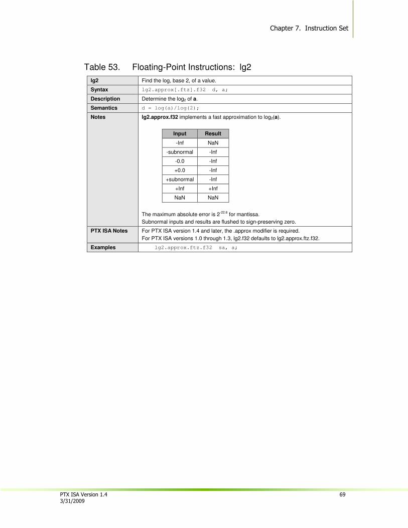
Chapter 7. Instruction Set
PTX ISA Version 1.4 69 3/31/2009
Table 53. Floating-Point Instructions: lg2
lg2 Find the log, base 2, of a value.
Syntax lg2.approx[.ftz].f32 d, a;
Description Determine the log2 of a.
Semantics d = log(a)/log(2);
Notes lg2.approx.f32 implements a fast approximation to log2(a).
Input Result
-Inf NaN
-subnormal -Inf
-0.0 -Inf
+0.0 -Inf
+subnormal -Inf
+Inf +Inf
NaN NaN
The maximum absolute error is 2-22.6
for mantissa.
Subnormal inputs and results are flushed to sign-preserving zero.
PTX ISA Notes For PTX ISA version 1.4 and later, the .approx modifier is required.
For PTX ISA versions 1.0 through 1.3, lg2.f32 defaults to lg2.approx.ftz.f32.
Examples lg2.approx.ftz.f32 sa, a;
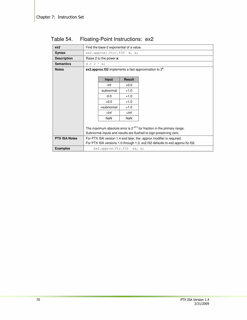
Chapter 7: Instruction Set
70 PTX ISA Version 1.4 3/31/2009
Table 54. Floating-Point Instructions: ex2
ex2 Find the base-2 exponential of a value.
Syntax ex2.approx[.ftz].f32 d, a;
Description Raise 2 to the power a.
Semantics d = 2 ^ a;
Notes ex2.approx.f32 implements a fast approximation to 2a.
Input Result
-Inf +0.0
-subnormal +1.0
-0.0 +1.0
+0.0 +1.0
+subnormal +1.0
+Inf +Inf
NaN NaN
The maximum absolute error is 2-22.5
for fraction in the primary range.
Subnormal inputs and results are flushed to sign-preserving zero.
PTX ISA Notes For PTX ISA version 1.4 and later, the .approx modifier is required.
For PTX ISA versions 1.0 through 1.3, ex2.f32 defaults to ex2.approx.ftz.f32.
Examples ex2.approx.ftz.f32 sa, a;
Chapter 7. Instruction Set
PTX ISA Version 1.4 71 3/31/2009
7.7.3. Comparison and Selection Instructions
The comparison select instructions are:
� set
� setp
� selp
� slct
As with single-precision floating-point instructions, the set, setp, and slct instructions flush single-precision subnormal inputs to sign-preserving zero. An optional .ftz modifier is provided to explicitly indicate this behavior.
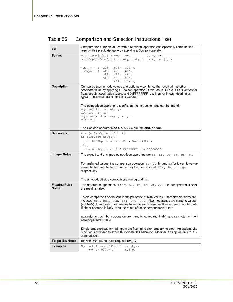
Chapter 7: Instruction Set
72 PTX ISA Version 1.4 3/31/2009
Table 55. Comparison and Selection Instructions: set
set Compare two numeric values with a relational operator, and optionally combine this result with a predicate value by applying a Boolean operator.
Syntax set.CmpOp[.ftz].dtype.stype d, a, b;
set.CmpOp.BoolOp[.ftz].dtype.stype d, a, b, [!]c;
.dtype = { .u32, .s32, .f32 };
.stype = { .b16, .b32, .b64,
.u16, .u32, .u64,
.s16, .s32, .s64,
.f32, .f64 };
Description Compares two numeric values and optionally combines the result with another predicate value by applying a Boolean operator. If this result is True, 1.0f is written for floating-point destination types, and 0xFFFFFFFF is written for integer destination types. Otherwise, 0x00000000 is written.
The comparison operator is a suffix on the instruction, and can be one of: eq, ne, lt, le, gt, ge
lo, ls, hi, hs
equ, neu, ltu, leu, gtu, geu
num, nan
The Boolean operator BoolOp(A,B) is one of: and, or, xor.
Semantics t = (a CmpOp b) ? 1 : 0;
if (isFloat(dtype))
d = BoolOp(t, c) ? 1.0f : 0x00000000;
else
d = BoolOp(t, c) ? 0xFFFFFFFF : 0x00000000;
Integer Notes The signed and unsigned comparison operators are eq, ne, lt, le, gt, ge.
For unsigned values, the comparison operators lo, ls, hi, and hs for lower, lower-or-
same, higher, and higher-or-same may be used instead of lt, le, gt, ge, respectively.
The untyped, bit-size comparisons are eq and ne.
Floating Point Notes
The ordered comparisons are eq, ne, lt, le, gt, ge. If either operand is NaN, the result is false.
To aid comparison operations in the presence of NaN values, unordered versions are included: equ, neu, ltu, leu, gtu, geu. If both operands are numeric values (not NaN), then these comparisons have the same result as their ordered counterparts. If either operand is NaN, then the result of these comparisons is true.
num returns true if both operands are numeric values (not NaN), and nan returns true if either operand is NaN.
Single-precision subnormal inputs are flushed to sign-preserving zero. An optional .ftz modifier is provided to explicitly indicate this behavior. Modifier .ftz applies only to .f32 comparisons.
Target ISA Notes set with .f64 source type requires sm_13.
Examples @p set.lt.and.f32.s32 d,a,b,r;
set.eq.u32.u32 d,i,n;
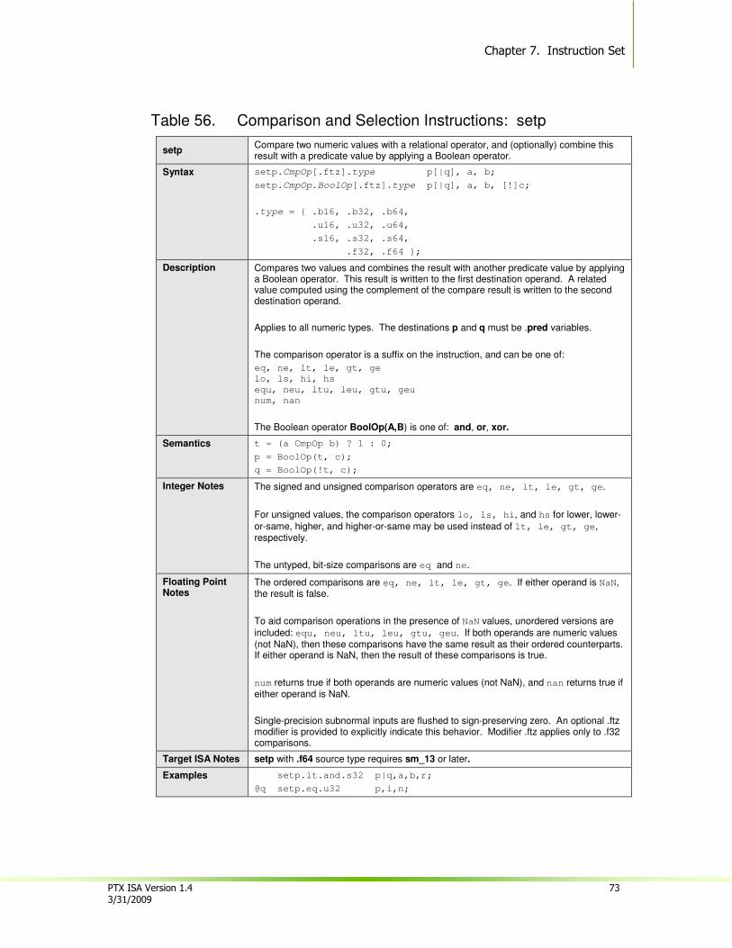
Chapter 7. Instruction Set
PTX ISA Version 1.4 73 3/31/2009
Table 56. Comparison and Selection Instructions: setp
setp Compare two numeric values with a relational operator, and (optionally) combine this result with a predicate value by applying a Boolean operator.
Syntax setp.CmpOp[.ftz].type p[|q], a, b;
setp.CmpOp.BoolOp[.ftz].type p[|q], a, b, [!]c;
.type = { .b16, .b32, .b64,
.u16, .u32, .u64,
.s16, .s32, .s64,
.f32, .f64 };
Description Compares two values and combines the result with another predicate value by applying a Boolean operator. This result is written to the first destination operand. A related value computed using the complement of the compare result is written to the second destination operand.
Applies to all numeric types. The destinations p and q must be .pred variables.
The comparison operator is a suffix on the instruction, and can be one of:
eq, ne, lt, le, gt, ge
lo, ls, hi, hs
equ, neu, ltu, leu, gtu, geu
num, nan
The Boolean operator BoolOp(A,B) is one of: and, or, xor.
Semantics t = (a CmpOp b) ? 1 : 0;
p = BoolOp(t, c);
q = BoolOp(!t, c);
Integer Notes The signed and unsigned comparison operators are eq, ne, lt, le, gt, ge.
For unsigned values, the comparison operators lo, ls, hi, and hs for lower, lower-
or-same, higher, and higher-or-same may be used instead of lt, le, gt, ge, respectively.
The untyped, bit-size comparisons are eq and ne.
Floating Point Notes
The ordered comparisons are eq, ne, lt, le, gt, ge. If either operand is NaN, the result is false.
To aid comparison operations in the presence of NaN values, unordered versions are
included: equ, neu, ltu, leu, gtu, geu. If both operands are numeric values (not NaN), then these comparisons have the same result as their ordered counterparts. If either operand is NaN, then the result of these comparisons is true.
num returns true if both operands are numeric values (not NaN), and nan returns true if either operand is NaN.
Single-precision subnormal inputs are flushed to sign-preserving zero. An optional .ftz modifier is provided to explicitly indicate this behavior. Modifier .ftz applies only to .f32 comparisons.
Target ISA Notes setp with .f64 source type requires sm_13 or later.
Examples setp.lt.and.s32 p|q,a,b,r;
@q setp.eq.u32 p,i,n;
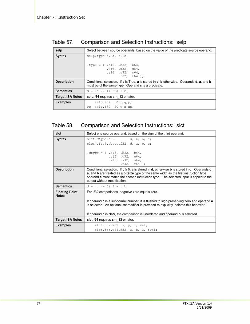
Chapter 7: Instruction Set
74 PTX ISA Version 1.4 3/31/2009
Table 57. Comparison and Selection Instructions: selp
selp Select between source operands, based on the value of the predicate source operand.
Syntax selp.type d, a, b, c;
.type = { .b16, .b32, .b64,
.u16, .u32, .u64,
.s16, .s32, .s64,
.f32, .f64 };
Description Conditional selection. If c is True, a is stored in d, b otherwise. Operands d, a, and b must be of the same type. Operand c is a predicate.
Semantics d = (c == 1) ? a : b;
Target ISA Notes selp.f64 requires sm_13 or later.
Examples selp.s32 r0,r,g,p;
@q selp.f32 f0,t,x,xp;
Table 58. Comparison and Selection Instructions: slct
slct Select one source operand, based on the sign of the third operand.
Syntax slct.dtype.s32 d, a, b, c;
slct[.ftz].dtype.f32 d, a, b, c;
.dtype = { .b16, .b32, .b64,
.u16, .u32, .u64,
.s16, .s32, .s64,
.f32, .f64 };
Description Conditional selection. If c ≥ 0, a is stored in d, otherwise b is stored in d. Operands d, a, and b are treated as a bitsize type of the same width as the first instruction type; operand c must match the second instruction type. The selected input is copied to the output without modification.
Semantics d = (c >= 0) ? a : b;
Floating Point Notes
For .f32 comparisons, negative zero equals zero.
If operand c is a subnormal number, it is flushed to sign-preserving zero and operand a is selected. An optional .ftz modifier is provided to explicitly indicate this behavior.
If operand c is NaN, the comparison is unordered and operand b is selected.
Target ISA Notes slct.f64 requires sm_13 or later.
Examples slct.u32.s32 x, y, z, val;
slct.ftz.u64.f32 A, B, C, fval;
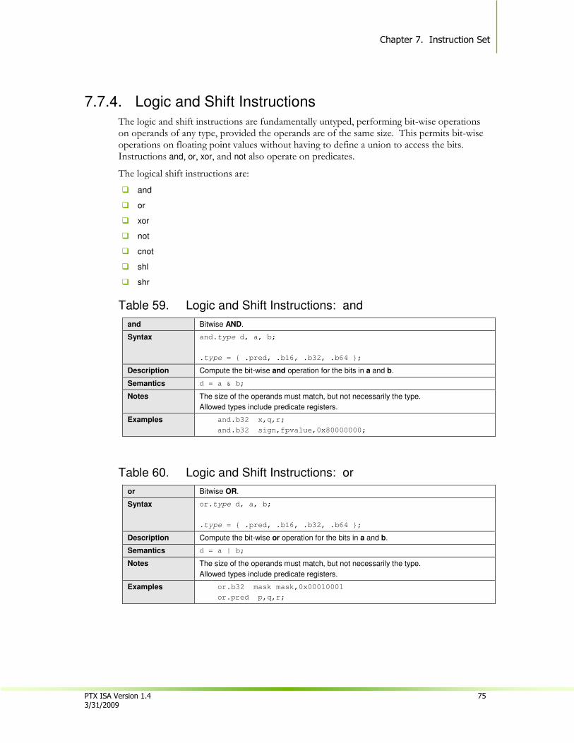
Chapter 7. Instruction Set
PTX ISA Version 1.4 75 3/31/2009
7.7.4. Logic and Shift Instructions
The logic and shift instructions are fundamentally untyped, performing bit-wise operations on operands of any type, provided the operands are of the same size. This permits bit-wise operations on floating point values without having to define a union to access the bits. Instructions and, or, xor, and not also operate on predicates.
The logical shift instructions are:
� and
� or
� xor
� not
� cnot
� shl
� shr
Table 59. Logic and Shift Instructions: and
and Bitwise AND.
Syntax and.type d, a, b;
.type = { .pred, .b16, .b32, .b64 };
Description Compute the bit-wise and operation for the bits in a and b.
Semantics d = a & b;
Notes The size of the operands must match, but not necessarily the type.
Allowed types include predicate registers.
Examples and.b32 x,q,r;
and.b32 sign,fpvalue,0x80000000;
Table 60. Logic and Shift Instructions: or
or Bitwise OR.
Syntax or.type d, a, b;
.type = { .pred, .b16, .b32, .b64 };
Description Compute the bit-wise or operation for the bits in a and b.
Semantics d = a | b;
Notes The size of the operands must match, but not necessarily the type.
Allowed types include predicate registers.
Examples or.b32 mask mask,0x00010001
or.pred p,q,r;
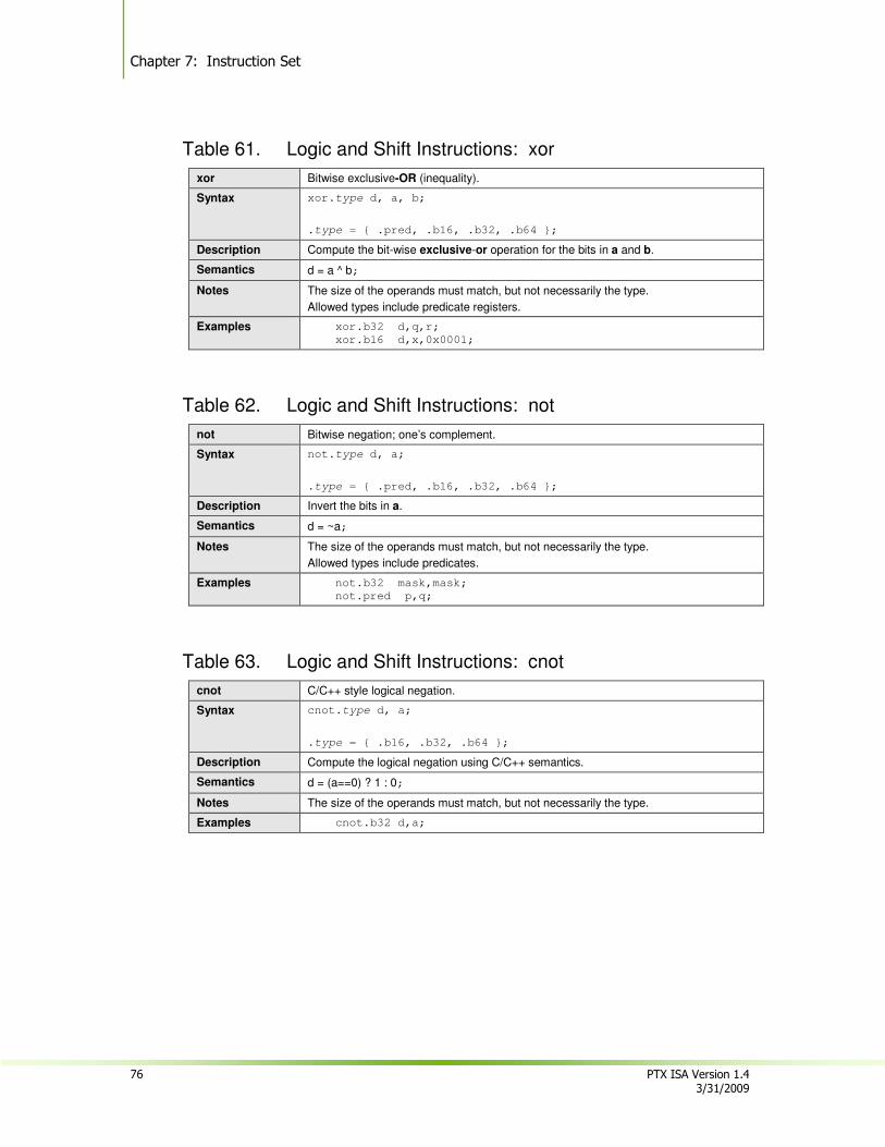
Chapter 7: Instruction Set
76 PTX ISA Version 1.4 3/31/2009
Table 61. Logic and Shift Instructions: xor
xor Bitwise exclusive-OR (inequality).
Syntax xor.type d, a, b;
.type = { .pred, .b16, .b32, .b64 };
Description Compute the bit-wise exclusive-or operation for the bits in a and b.
Semantics d = a ^ b;
Notes The size of the operands must match, but not necessarily the type.
Allowed types include predicate registers.
Examples xor.b32 d,q,r;
xor.b16 d,x,0x0001;
Table 62. Logic and Shift Instructions: not
not Bitwise negation; one’s complement.
Syntax not.type d, a;
.type = { .pred, .b16, .b32, .b64 };
Description Invert the bits in a.
Semantics d = ~a;
Notes The size of the operands must match, but not necessarily the type.
Allowed types include predicates.
Examples not.b32 mask,mask;
not.pred p,q;
Table 63. Logic and Shift Instructions: cnot
cnot C/C++ style logical negation.
Syntax cnot.type d, a;
.type = { .b16, .b32, .b64 };
Description Compute the logical negation using C/C++ semantics.
Semantics d = (a==0) ? 1 : 0;
Notes The size of the operands must match, but not necessarily the type.
Examples cnot.b32 d,a;
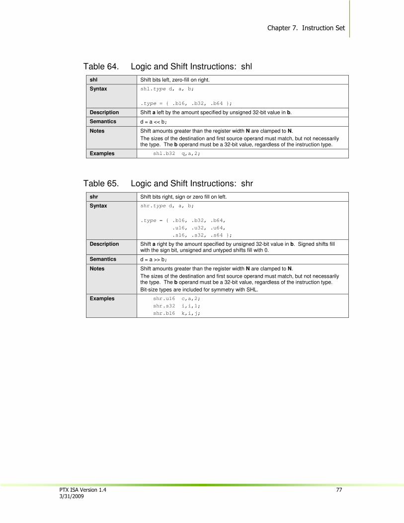
Chapter 7. Instruction Set
PTX ISA Version 1.4 77 3/31/2009
Table 64. Logic and Shift Instructions: shl
shl Shift bits left, zero-fill on right.
Syntax shl.type d, a, b;
.type = { .b16, .b32, .b64 };
Description Shift a left by the amount specified by unsigned 32-bit value in b.
Semantics d = a << b;
Notes Shift amounts greater than the register width N are clamped to N.
The sizes of the destination and first source operand must match, but not necessarily the type. The b operand must be a 32-bit value, regardless of the instruction type.
Examples shl.b32 q,a,2;
Table 65. Logic and Shift Instructions: shr
shr Shift bits right, sign or zero fill on left.
Syntax shr.type d, a, b;
.type = { .b16, .b32, .b64,
.u16, .u32, .u64,
.s16, .s32, .s64 };
Description Shift a right by the amount specified by unsigned 32-bit value in b. Signed shifts fill with the sign bit, unsigned and untyped shifts fill with 0.
Semantics d = a >> b;
Notes Shift amounts greater than the register width N are clamped to N.
The sizes of the destination and first source operand must match, but not necessarily the type. The b operand must be a 32-bit value, regardless of the instruction type.
Bit-size types are included for symmetry with SHL.
Examples shr.u16 c,a,2;
shr.s32 i,i,1;
shr.b16 k,i,j;
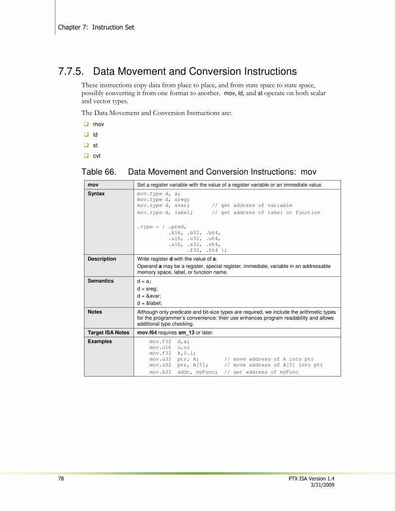
Chapter 7: Instruction Set
78 PTX ISA Version 1.4 3/31/2009
7.7.5. Data Movement and Conversion Instructions
These instructions copy data from place to place, and from state space to state space, possibly converting it from one format to another. mov, ld, and st operate on both scalar and vector types.
The Data Movement and Conversion Instructions are:
� mov
� ld
� st
� cvt
Table 66. Data Movement and Conversion Instructions: mov
mov Set a register variable with the value of a register variable or an immediate value.
Syntax mov.type d, a;
mov.type d, sreg;
mov.type d, avar; // get address of variable
mov.type d, label; // get address of label or function
.type = { .pred,
.b16, .b32, .b64,
.u16, .u32, .u64,
.s16, .s32, .s64,
.f32, .f64 };
Description Write register d with the value of a.
Operand a may be a register, special register, immediate, variable in an addressable memory space, label, or function name.
Semantics d = a;
d = sreg;
d = &avar;
d = &label;
Notes Although only predicate and bit-size types are required, we include the arithmetic types for the programmer’s convenience: their use enhances program readability and allows additional type checking.
Target ISA Notes mov.f64 requires sm_13 or later.
Examples mov.f32 d,a;
mov.u16 u,v;
mov.f32 k,0.1;
mov.u32 ptr, A; // move address of A into ptr
mov.u32 ptr, A[5]; // move address of A[5] into ptr
mov.b32 addr, myFunc; // get address of myFunc
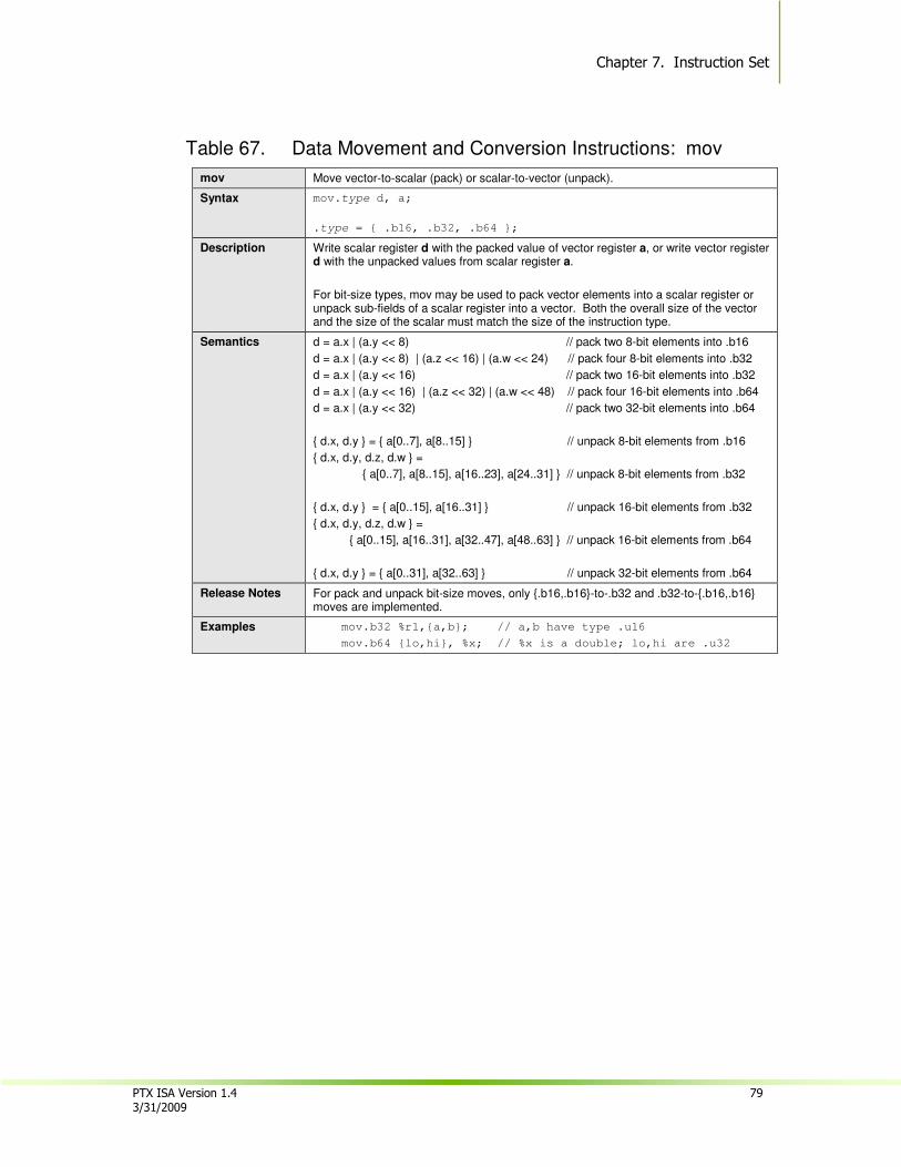
Chapter 7. Instruction Set
PTX ISA Version 1.4 79 3/31/2009
Table 67. Data Movement and Conversion Instructions: mov
mov Move vector-to-scalar (pack) or scalar-to-vector (unpack).
Syntax mov.type d, a;
.type = { .b16, .b32, .b64 };
Description Write scalar register d with the packed value of vector register a, or write vector register d with the unpacked values from scalar register a.
For bit-size types, mov may be used to pack vector elements into a scalar register or unpack sub-fields of a scalar register into a vector. Both the overall size of the vector and the size of the scalar must match the size of the instruction type.
Semantics d = a.x | (a.y << 8) // pack two 8-bit elements into .b16
d = a.x | (a.y << 8) | (a.z << 16) | (a.w << 24) // pack four 8-bit elements into .b32
d = a.x | (a.y << 16) // pack two 16-bit elements into .b32
d = a.x | (a.y << 16) | (a.z << 32) | (a.w << 48) // pack four 16-bit elements into .b64
d = a.x | (a.y << 32) // pack two 32-bit elements into .b64
{ d.x, d.y } = { a[0..7], a[8..15] } // unpack 8-bit elements from .b16
{ d.x, d.y, d.z, d.w } =
{ a[0..7], a[8..15], a[16..23], a[24..31] } // unpack 8-bit elements from .b32
{ d.x, d.y } = { a[0..15], a[16..31] } // unpack 16-bit elements from .b32
{ d.x, d.y, d.z, d.w } =
{ a[0..15], a[16..31], a[32..47], a[48..63] } // unpack 16-bit elements from .b64
{ d.x, d.y } = { a[0..31], a[32..63] } // unpack 32-bit elements from .b64
Release Notes For pack and unpack bit-size moves, only {.b16,.b16}-to-.b32 and .b32-to-{.b16,.b16} moves are implemented.
Examples mov.b32 %r1,{a,b}; // a,b have type .u16
mov.b64 {lo,hi}, %x; // %x is a double; lo,hi are .u32
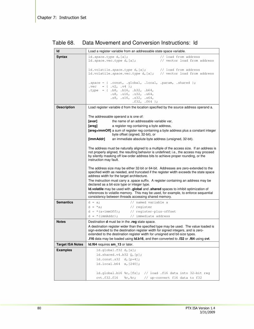
Chapter 7: Instruction Set
80 PTX ISA Version 1.4 3/31/2009
Table 68. Data Movement and Conversion Instructions: ld
ld Load a register variable from an addressable state space variable.
Syntax ld.space.type d,[a]; // load from address
ld.space.vec.type d,[a]; // vector load from address
ld.volatile.space.type d,[a]; // load from address
ld.volatile.space.vec.type d,[a]; // vector load from address
.space = { .const, .global, .local, .param, .shared };
.vec = { .v2, .v4 };
.type = { .b8, .b16, .b32, .b64,
.u8, .u16, .u32, .u64,
.s8, .s16, .s32, .s64,
.f32, .f64 };
Description Load register variable d from the location specified by the source address operand a.
The addressable operand a is one of:
[avar] the name of an addressable variable var,
[areg] a register reg containing a byte address,
[areg+immOff] a sum of register reg containing a byte address plus a constant integer byte offset (signed, 32-bit), or
[immAddr] an immediate absolute byte address (unsigned, 32-bit).
The address must be naturally aligned to a multiple of the access size. If an address is not properly aligned, the resulting behavior is undefined; i.e., the access may proceed by silently masking off low-order address bits to achieve proper rounding, or the instruction may fault.
The address size may be either 32-bit or 64-bit. Addresses are zero-extended to the specified width as needed, and truncated if the register width exceeds the state space address width for the target architecture.
The instruction must carry a .space suffix. A register containing an address may be declared as a bit-size type or integer type.
ld.volatile may be used with .global and .shared spaces to inhibit optimization of references to volatile memory. This may be used, for example, to enforce sequential consistency between threads accessing shared memory.
Semantics d = a; // named variable a
d = *a; // register
d = *(a+immOff); // register-plus-offset
d = *(immAddr); // immediate address
Notes Destination d must be in the .reg state space.
A destination register wider than the specified type may be used. The value loaded is sign-extended to the destination register width for signed integers, and is zero-extended to the destination register width for unsigned and bit-size types.
.f16 data may be loaded using ld.b16, and then converted to .f32 or .f64 using cvt.
Target ISA Notes ld.f64 requires sm_13 or later.
Examples ld.global.f32 d,[a];
ld.shared.v4.b32 Q,[p];
ld.const.s32 d,[p+4];
ld.local.b64 x,[240];
ld.global.b16 %r,[fs]; // load .f16 data into 32-bit reg
cvt.f32.f16 %r,%r; // up-convert f16 data to f32
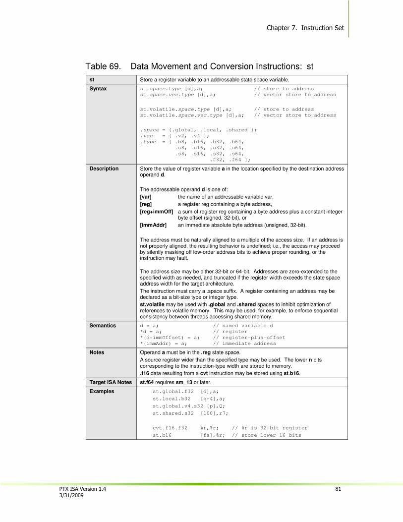
Chapter 7. Instruction Set
PTX ISA Version 1.4 81 3/31/2009
Table 69. Data Movement and Conversion Instructions: st
st Store a register variable to an addressable state space variable.
Syntax st.space.type [d],a; // store to address
st.space.vec.type [d],a; // vector store to address
st.volatile.space.type [d],a; // store to address
st.volatile.space.vec.type [d],a; // vector store to address
.space = {.global, .local, .shared };
.vec = { .v2, .v4 };
.type = { .b8, .b16, .b32, .b64,
.u8, .u16, .u32, .u64,
.s8, .s16, .s32, .s64,
.f32, .f64 };
Description Store the value of register variable a in the location specified by the destination address operand d.
The addressable operand d is one of:
[var] the name of an addressable variable var,
[reg] a register reg containing a byte address,
[reg+immOff] a sum of register reg containing a byte address plus a constant integer byte offset (signed, 32-bit), or
[immAddr] an immediate absolute byte address (unsigned, 32-bit).
The address must be naturally aligned to a multiple of the access size. If an address is not properly aligned, the resulting behavior is undefined; i.e., the access may proceed by silently masking off low-order address bits to achieve proper rounding, or the instruction may fault.
The address size may be either 32-bit or 64-bit. Addresses are zero-extended to the specified width as needed, and truncated if the register width exceeds the state space address width for the target architecture.
The instruction must carry a .space suffix. A register containing an address may be declared as a bit-size type or integer type.
st.volatile may be used with .global and .shared spaces to inhibit optimization of references to volatile memory. This may be used, for example, to enforce sequential consistency between threads accessing shared memory.
Semantics d = a; // named variable d
*d = a; // register
*(d+immOffset) = a; // register-plus-offset
*(immAddr) = a; // immediate address
Notes Operand a must be in the .reg state space.
A source register wider than the specified type may be used. The lower n bits corresponding to the instruction-type width are stored to memory.
.f16 data resulting from a cvt instruction may be stored using st.b16.
Target ISA Notes st.f64 requires sm_13 or later.
Examples st.global.f32 [d],a;
st.local.b32 [q+4],a;
st.global.v4.s32 [p],Q;
st.shared.s32 [100],r7;
cvt.f16.f32 %r,%r; // %r is 32-bit register
st.b16 [fs],%r; // store lower 16 bits

Chapter 7: Instruction Set
82 PTX ISA Version 1.4 3/31/2009
Table 70. Data Movement and Conversion Instructions: cvt
cvt Convert a value from one type to another.
Syntax cvt[.rnd][.ftz][.sat].dtype.atype d, a;
.dtype = .atype = { .u8, .u16, .u32, .u64,
.s8, .s16, .s32, .s64,
.f16, .f32, .f64 };
Description Convert between different types and sizes.
Semantics d = convert(a);
Integer Notes Integer rounding is required for float-to-integer conversions, and for same-size float-to-float conversions where the value is rounded to an integer. Integer rounding is illegal in all other instances.
Integer rounding modifiers:
.rni round to nearest integer, choosing even integer if source is equidistant between two integers.
.rzi round to nearest integer in the direction of zero
.rmi round to nearest integer in direction of negative infinity
.rpi round to nearest integer in direction of positive infinity
For float-to-integer conversions and same-size float-to-float conversions with integer rounding, single-precision subnormal inputs are flushed to sign-preserving zero provided the destination type is not .u64 or .s64. The optional .ftz modifier may be specified in these cases for clarity. This restriction to non-.u64/.s64 types is considered an errata and may be fixed in future versions of PTX.
Saturation modifier:
.sat For integer destination types, .sat limits the result to MININT..MAXINT for the size of the operation. Note that saturation applies to both signed and unsigned integer types. Saturation is illegal for small-to-large integer-to-integer conversions, except for the signed-to-unsigned case. For float-to-integer conversions, the result is clamped to the destination range by default; i.e, .sat is redundant.
Floating Point Notes
Floating-point rounding is required for float-to-float conversions that result in loss of precision, and for integer-to-float conversions. Floating-point rounding is illegal in all other instances.
Floating-point rounding modifiers:
.rn mantissa LSB rounds to nearest even
.rz mantissa LSB rounds towards zero
.rm mantissa LSB rounds towards negative infinity
.rp mantissa LSB rounds towards positive infinity
A floating-point value may be rounded to an integral value using the integer rounding modifiers (see Integer Notes). The operands must be of the same size. The result is an integral value, stored in floating-point format.
Subnormal numbers:
Single-precision subnormal inputs and results are flushed to sign-preserving zero, provided neither source nor destination type is .f64. More specifically, flush-to-zero behavior applies to cvt.f32.f16, cvt.f16.f32, and cvt.f32.f32. The optional .ftz modifier may be specified in these cases for clarity. This restriction to non-.f64 types is considered an errata and may be fixed in future versions of PTX.
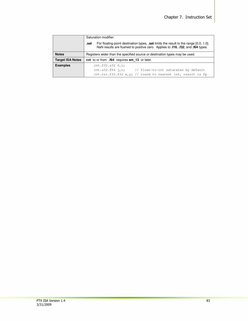
Chapter 7. Instruction Set
PTX ISA Version 1.4 83 3/31/2009
Saturation modifier:
.sat For floating-point destination types, .sat limits the result to the range [0.0, 1.0]. NaN results are flushed to positive zero. Applies to .f16, .f32, and .f64 types.
Notes Registers wider than the specified source or destination types may be used.
Target ISA Notes cvt to or from .f64 requires sm_13 or later.
Examples cvt.f32.s32 f,i;
cvt.s32.f64 j,r; // float-to-int saturates by default
cvt.rni.f32.f32 x,y; // round to nearest int, result is fp

Chapter 7: Instruction Set
84 PTX ISA Version 1.4 3/31/2009
7.7.6. Texture Instruction
The tex instruction provides access to texture memory.
� tex
Table 71. Texture Instruction: tex
tex Perform a texture memory lookup.
Syntax tex.geom.v4.dtype.btype d, [a, c];
.geom = { .1d, .2d, .3d };
.dtype = { .u32, .s32, .f32 };
.btype = { .s32, .f32 };
Description Texture lookup using a texture coordinate vector. The instruction loads data from the texture named by operand a at coordinates given by operand c into destination d. Operand c is a scalar or singleton tuple for 1d textures; is a two-element vector for 2d textures; and is a four-element vector for 3d textures, where the fourth element is ignored.
The instruction always returns a four-element vector of 32-bit values. Coordinates may be given in either signed 32-bit integer or 32-bit floating point form. A texture base address is assumed to be aligned to a 16-byte address, and the address given by the coordinate vector must be naturally aligned to a multiple of the access size. If an address is not properly aligned, the resulting behavior is undefined; i.e., the access may proceed by silently masking off low-order address bits to achieve proper rounding, or the instruction may fault.
Notes For compatibility with prior versions of PTX, the square brackets are not required and .v4 coordinate vectors are allowed for any geometry, with the extra elements being ignored.
Examples tex.3d.v4.s32.s32 {r1,r2,r3,r4}, [tex_a, {f1,f2,f3,f4}];
tex.1d.v4.s32.f32 {r1,r2,r3,r4}, [tex_a, {f1}];
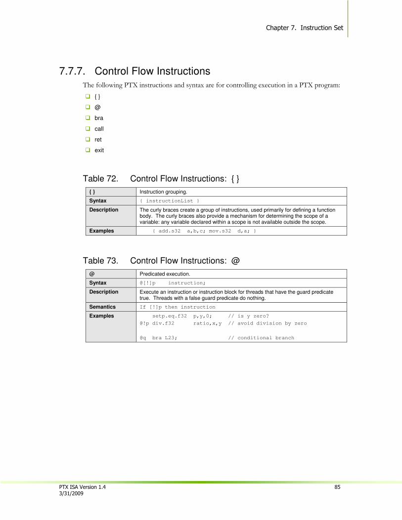
Chapter 7. Instruction Set
PTX ISA Version 1.4 85 3/31/2009
7.7.7. Control Flow Instructions
The following PTX instructions and syntax are for controlling execution in a PTX program:
� { }
� @
� bra
� call
� ret
� exit
Table 72. Control Flow Instructions: { }
{ } Instruction grouping.
Syntax { instructionList }
Description The curly braces create a group of instructions, used primarily for defining a function body. The curly braces also provide a mechanism for determining the scope of a variable: any variable declared within a scope is not available outside the scope.
Examples { add.s32 a,b,c; mov.s32 d,a; }
Table 73. Control Flow Instructions: @
@ Predicated execution.
Syntax @[!]p instruction;
Description Execute an instruction or instruction block for threads that have the guard predicate true. Threads with a false guard predicate do nothing.
Semantics If [!]p then instruction
Examples setp.eq.f32 p,y,0; // is y zero?
@!p div.f32 ratio,x,y // avoid division by zero
@q bra L23; // conditional branch
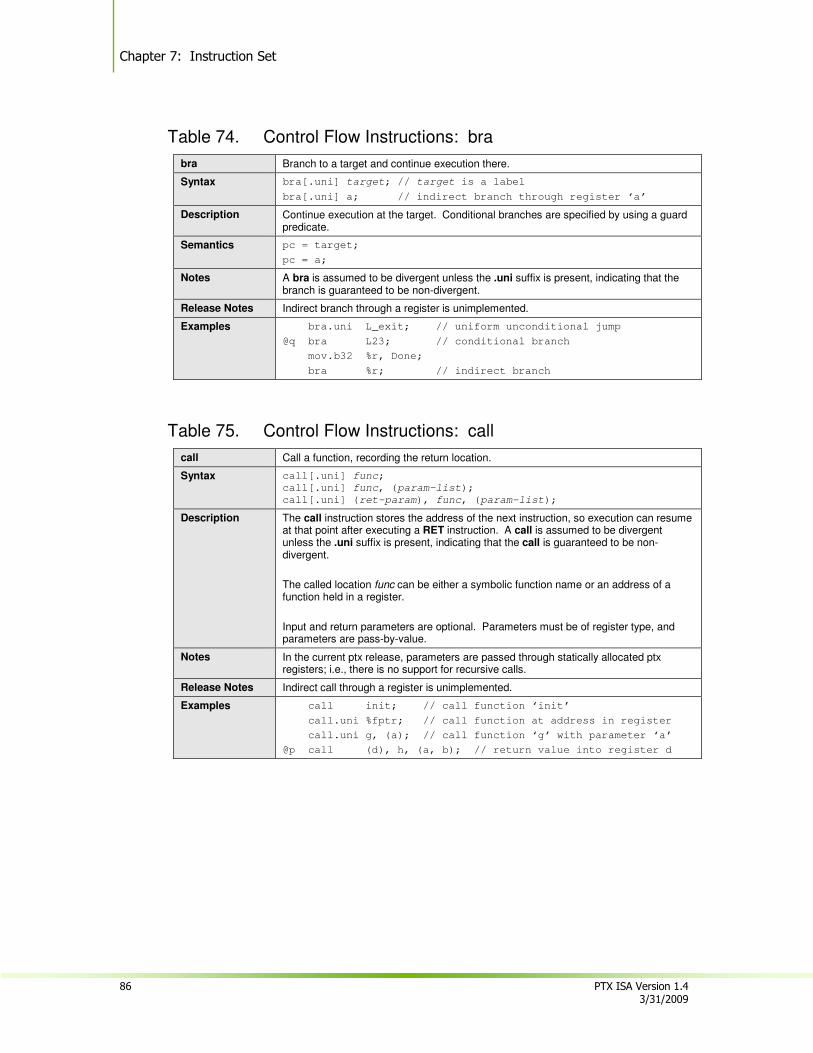
Chapter 7: Instruction Set
86 PTX ISA Version 1.4 3/31/2009
Table 74. Control Flow Instructions: bra
bra Branch to a target and continue execution there.
Syntax bra[.uni] target; // target is a label
bra[.uni] a; // indirect branch through register ‘a’
Description Continue execution at the target. Conditional branches are specified by using a guard predicate.
Semantics pc = target;
pc = a;
Notes A bra is assumed to be divergent unless the .uni suffix is present, indicating that the branch is guaranteed to be non-divergent.
Release Notes Indirect branch through a register is unimplemented.
Examples bra.uni L_exit; // uniform unconditional jump
@q bra L23; // conditional branch
mov.b32 %r, Done;
bra %r; // indirect branch
Table 75. Control Flow Instructions: call
call Call a function, recording the return location.
Syntax call[.uni] func;
call[.uni] func, (param-list);
call[.uni] (ret-param), func, (param-list);
Description The call instruction stores the address of the next instruction, so execution can resume at that point after executing a RET instruction. A call is assumed to be divergent unless the .uni suffix is present, indicating that the call is guaranteed to be non-divergent.
The called location func can be either a symbolic function name or an address of a function held in a register.
Input and return parameters are optional. Parameters must be of register type, and parameters are pass-by-value.
Notes In the current ptx release, parameters are passed through statically allocated ptx registers; i.e., there is no support for recursive calls.
Release Notes Indirect call through a register is unimplemented.
Examples call init; // call function ‘init’
call.uni %fptr; // call function at address in register
call.uni g, (a); // call function ‘g’ with parameter ‘a’
@p call (d), h, (a, b); // return value into register d
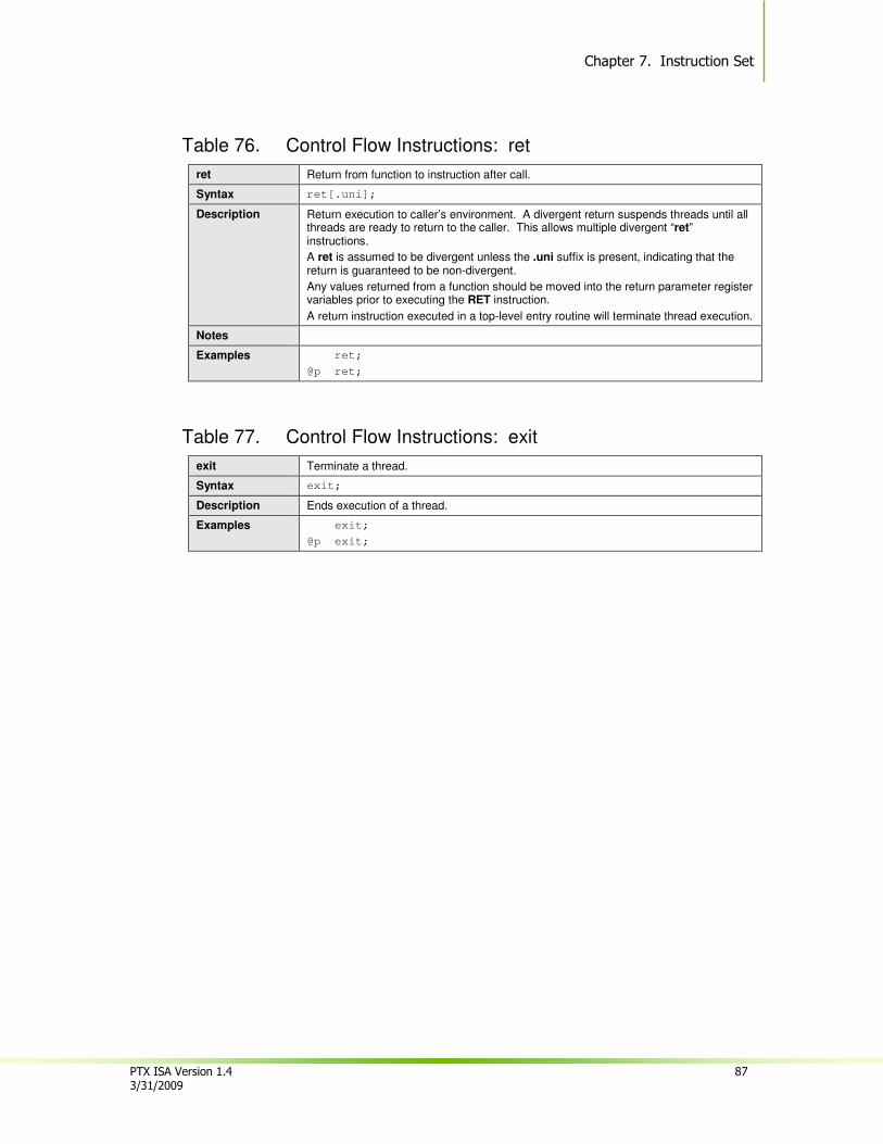
Chapter 7. Instruction Set
PTX ISA Version 1.4 87 3/31/2009
Table 76. Control Flow Instructions: ret
ret Return from function to instruction after call.
Syntax ret[.uni];
Description Return execution to caller’s environment. A divergent return suspends threads until all threads are ready to return to the caller. This allows multiple divergent “ret” instructions.
A ret is assumed to be divergent unless the .uni suffix is present, indicating that the return is guaranteed to be non-divergent.
Any values returned from a function should be moved into the return parameter register variables prior to executing the RET instruction.
A return instruction executed in a top-level entry routine will terminate thread execution.
Notes
Examples ret;
@p ret;
Table 77. Control Flow Instructions: exit
exit Terminate a thread.
Syntax exit;
Description Ends execution of a thread.
Examples exit;
@p exit;

Chapter 7: Instruction Set
88 PTX ISA Version 1.4 3/31/2009
7.7.8. Parallel Synchronization and Communication Instructions
These instructions are:
� bar
� membar
� atom
� red
� vote

Chapter 7. Instruction Set
PTX ISA Version 1.4 89 3/31/2009
Table 78. Parallel Synchronization and Communication Instructions: bar
bar Signal arrival at a barrier and wait.
Syntax bar.sync d;
Description Marks the arrival of threads at a barrier and waits for all other threads to arrive.
The barrier resource is named via a small integer, typically in the range 0..15. The barrier number may be given as an immediate.
Notes The hardware has a limited, implementation-specific number of barrier resources, typically sixteen or fewer. Since a CTA will not launch until all allocated resources are available, a program should minimize the number of distinct barrier variables allocated. Ideally, a program uses a single, global barrier that is re-used throughout the program.
Examples bar.sync 0;
Table 79. Parallel Synchronization and Communication Instructions: membar
membar Memory barrier.
Syntax membar.level;
.level = { .gl, .cta };
Description Waits for all prior memory accesses requested by this thread to be performed at the CTA or global memory level. Level describes the scope of other clients for which membar is an ordering event. Thread execution resumes after a membar when the thread's prior memory writes are visible to other threads at the specified level, and memory reads by this thread can no longer be affected by other thread writes.
A memory read (e.g. by ld or atom) has been performed when the value read has been transmitted from memory and cannot be modified by another thread at the indicated level. A memory write (e.g. by st, red or atom) has been performed when the value written has become visible to other clients at the specified level, that is, when the previous value can no longer be read.
• membar.cta waits for prior memory accesses to complete relative to other threads in the CTA.
• membar.gl waits for prior memory accesses to complete relative to other threads in the device.
Notes
Examples membar.gl;
membar.cta;
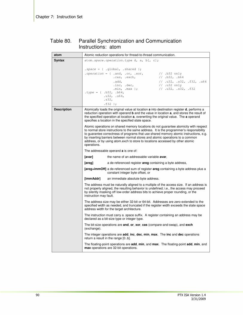
Chapter 7: Instruction Set
90 PTX ISA Version 1.4 3/31/2009
Table 80. Parallel Synchronization and Communication Instructions: atom
atom Atomic reduction operations for thread-to-thread communication.
Syntax atom.space.operation.type d, a, b[, c];
.space = { .global, .shared };
.operation = { .and, .or, .xor, // .b32 only
.cas, .exch, // .b32, .b64
.add, // .u32, .s32, .f32, .u64
.inc, .dec, // .u32 only
.min, .max }; // .u32, .s32, .f32
.type = { .b32, .b64,
.u32, .u64,
.s32,
.f32 };
Description Atomically loads the original value at location a into destination register d, performs a reduction operation with operand b and the value in location a, and stores the result of the specified operation at location a, overwriting the original value. The a operand specifies a location in the specified state space.
Atomic operations on shared memory locations do not guarantee atomicity with respect to normal store instructions to the same address. It is the programmer’s responsibility to guarantee correctness of programs that use shared memory atomic instructions, e.g. by inserting barriers between normal stores and atomic operations to a common address, or by using atom.exch to store to locations accessed by other atomic operations.
The addressable operand a is one of:
[avar] the name of an addressable variable avar,
[areg] a de-referenced register areg containing a byte address,
[areg+immOff] a de-referenced sum of register areg containing a byte address plus a constant integer byte offset, or
[immAddr] an immediate absolute byte address.
The address must be naturally aligned to a multiple of the access size. If an address is not properly aligned, the resulting behavior is undefined; i.e., the access may proceed by silently masking off low-order address bits to achieve proper rounding, or the instruction may fault.
The address size may be either 32-bit or 64-bit. Addresses are zero-extended to the specified width as needed, and truncated if the register width exceeds the state space address width for the target architecture.
The instruction must carry a .space suffix. A register containing an address may be declared as a bit-size type or integer type.
The bit-size operations are and, or, xor, cas (compare-and-swap), and exch (exchange).
The integer operations are add, inc, dec, min, max. The inc and dec operations return a result in the range [0..b].
The floating-point operations are add, min, and max. The floating-point add, min, and max operations are 32-bit operations.
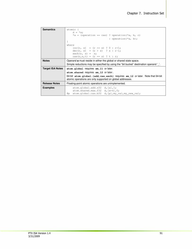
Chapter 7. Instruction Set
PTX ISA Version 1.4 91 3/31/2009
Semantics atomic {
d = *a;
*a = (operation == cas) ? operation(*a, b, c)
: operation(*a, b);
}
where
inc(r, s) = (r >= s) ? 0 : r+1;
dec(r, s) = (r > s) ? s : r-1;
exch(r, s) = s;
cas(r,s,t) = (r == s) ? t : r;
Notes Operand a must reside in either the global or shared state space.
Simple reductions may be specified by using the “bit bucket” destination operand ‘_’.
Target ISA Notes atom.global requires sm_11 or later.
atom.shared requires sm_12 or later.
64-bit atom.global.{add,cas,exch} requires sm_12 or later. Note that 64-bit
atomic operations are only supported on global addresses.
Release Notes Floating-point atomic operations are unimplemented.
Examples atom.global.add.s32 d,[a],1;
atom.shared.max.f32 d,[x+4],0;
@p atom.global.cas.b32 d,[p],my_val,my_new_val;

Chapter 7: Instruction Set
92 PTX ISA Version 1.4 3/31/2009
Table 81. Parallel Synchronization and Communication Instructions: red
red Reduction operations on global and shared memory.
Syntax red.space.operation.type a, b;
.space = { .global, .shared };
.operation = { .and, .or, .xor, // .b32 only
.add, // .u32, .s32, .f32, .u64
.inc, .dec, // .u32 only
.min, .max }; // .u32, .s32, .f32
.type = { .b32, .b64,
.u32, .u64,
.s32,
.f32 };
Description Performs a reduction operation with operand b and the value in location a, and stores the result of the specified operation at location a, overwriting the original value. The a operand specifies a location in the specified state space.
Reduction operations on shared memory locations do not guarantee atomicity with respect to normal store instructions to the same address. It is the programmer’s responsibility to guarantee correctness of programs that use shared memory reduction instructions, e.g. by inserting barriers between normal stores and reduction operations to a common address, or by using atom.exch to store to locations accessed by other reduction operations.
The addressable operand a is one of:
[avar] the name of an addressable variable avar,
[areg] a de-referenced register areg containing a byte address,
[areg+immOff] a de-referenced sum of register areg containing a byte address plus a constant integer byte offset, or
[immAddr] an immediate absolute byte address.
The address must be naturally aligned to a multiple of the access size. If an address is not properly aligned, the resulting behavior is undefined; i.e., the access may proceed by silently masking off low-order address bits to achieve proper rounding, or the instruction may fault.
The address size may be either 32-bit or 64-bit. Addresses are zero-extended to the specified width as needed, and truncated if the register width exceeds the state space address width for the target architecture.
The instruction must carry a .space suffix. A register containing an address may be declared as a bit-size type or integer type.
The bit-size operations are and, or, and xor.
The integer operations are add, inc, dec, min, max. The inc and dec operations return a result in the range [0..b].
The floating-point operations are add, min, and max. The floating-point add, min, and max operations are 32-bit operations.
Semantics *a = operation(*a, b);
where
inc(r, s) = (r >= s) ? 0 : r+1;
dec(r, s) = (r > s) ? s : r-1;
Notes Operand a must reside in either the global or shared state space.
Target ISA Notes red.global requires sm_11 or later.
red.shared requires sm_12 or later.
64-bit red.global.add requires sm_12 or later. Note that 64-bit reductions are
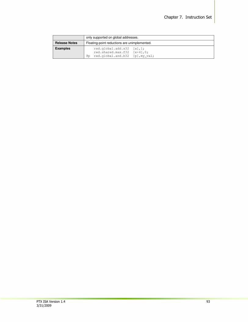
Chapter 7. Instruction Set
PTX ISA Version 1.4 93 3/31/2009
only supported on global addresses.
Release Notes Floating-point reductions are unimplemented.
Examples red.global.add.s32 [a],1;
red.shared.max.f32 [x+4],0;
@p red.global.and.b32 [p],my_val;
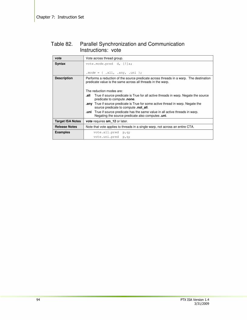
Chapter 7: Instruction Set
94 PTX ISA Version 1.4 3/31/2009
Table 82. Parallel Synchronization and Communication Instructions: vote
vote Vote across thread group.
Syntax vote.mode.pred d, [!]a;
.mode = { .all, .any, .uni };
Description Performs a reduction of the source predicate across threads in a warp. The destination predicate value is the same across all threads in the warp.
The reduction modes are:
.all True if source predicate is True for all active threads in warp. Negate the source predicate to compute .none.
.any True if source predicate is True for some active thread in warp. Negate the source predicate to compute .not_all.
.uni True if source predicate has the same value in all active threads in warp. Negating the source predicate also computes .uni.
Target ISA Notes vote requires sm_12 or later.
Release Notes Note that vote applies to threads in a single warp, not across an entire CTA.
Examples vote.all.pred p,q;
vote.uni.pred p,q;
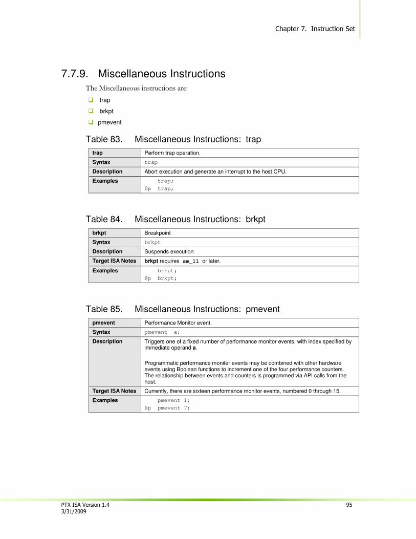
Chapter 7. Instruction Set
PTX ISA Version 1.4 95 3/31/2009
7.7.9. Miscellaneous Instructions
The Miscellaneous instructions are:
� trap
� brkpt
� pmevent
Table 83. Miscellaneous Instructions: trap
trap Perform trap operation.
Syntax trap
Description Abort execution and generate an interrupt to the host CPU.
Examples trap;
@p trap;
Table 84. Miscellaneous Instructions: brkpt
brkpt Breakpoint
Syntax brkpt
Description Suspends execution
Target ISA Notes brkpt requires sm_11 or later.
Examples brkpt;
@p brkpt;
Table 85. Miscellaneous Instructions: pmevent
pmevent Performance Monitor event.
Syntax pmevent a;
Description Triggers one of a fixed number of performance monitor events, with index specified by immediate operand a.
Programmatic performance moniter events may be combined with other hardware events using Boolean functions to increment one of the four performance counters. The relationship between events and counters is programmed via API calls from the host.
Target ISA Notes Currently, there are sixteen performance monitor events, numbered 0 through 15.
Examples pmevent 1;
@p pmevent 7;
Chapter 7: Instruction Set
96 PTX ISA Version 1.4 3/31/2009
This page is blank.
PTX ISA Version 1.4 97 3/31/2009
Chapter 8.
Special Registers
PTX includes a number of predefined, read-only variables, which are visible as special registers and accessed through mov or cvt instructions.
The special registers are:
� %tid
� %ntid
� %laneid
� %warpid
� %ctaid
� %nctaid
� %smid
� %nsmid
� %gridid
� %clock
� %pm0, …, %pm3
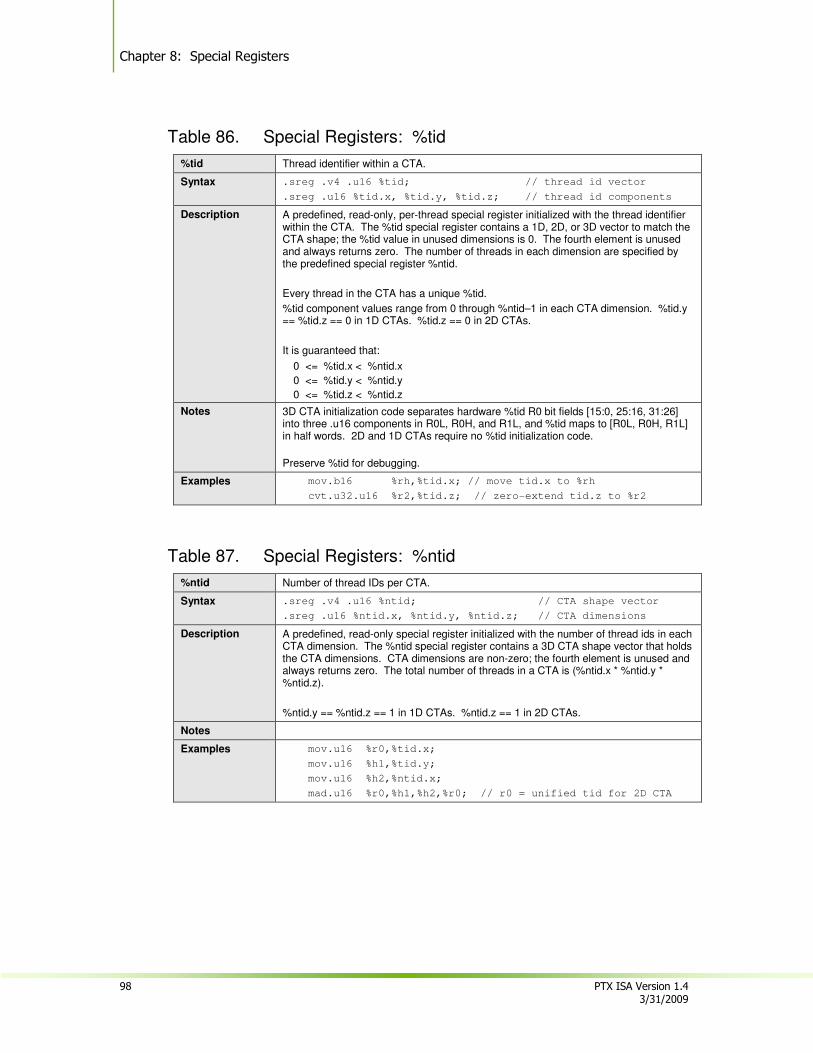
Chapter 8: Special Registers
98 PTX ISA Version 1.4 3/31/2009
Table 86. Special Registers: %tid
%tid Thread identifier within a CTA.
Syntax .sreg .v4 .u16 %tid; // thread id vector
.sreg .u16 %tid.x, %tid.y, %tid.z; // thread id components
Description A predefined, read-only, per-thread special register initialized with the thread identifier within the CTA. The %tid special register contains a 1D, 2D, or 3D vector to match the CTA shape; the %tid value in unused dimensions is 0. The fourth element is unused and always returns zero. The number of threads in each dimension are specified by the predefined special register %ntid.
Every thread in the CTA has a unique %tid.
%tid component values range from 0 through %ntid–1 in each CTA dimension. %tid.y == %tid.z == 0 in 1D CTAs. %tid.z == 0 in 2D CTAs.
It is guaranteed that:
0 <= %tid.x < %ntid.x
0 <= %tid.y < %ntid.y
0 <= %tid.z < %ntid.z
Notes 3D CTA initialization code separates hardware %tid R0 bit fields [15:0, 25:16, 31:26] into three .u16 components in R0L, R0H, and R1L, and %tid maps to [R0L, R0H, R1L] in half words. 2D and 1D CTAs require no %tid initialization code.
Preserve %tid for debugging.
Examples mov.b16 %rh,%tid.x; // move tid.x to %rh
cvt.u32.u16 %r2,%tid.z; // zero-extend tid.z to %r2
Table 87. Special Registers: %ntid
%ntid Number of thread IDs per CTA.
Syntax .sreg .v4 .u16 %ntid; // CTA shape vector
.sreg .u16 %ntid.x, %ntid.y, %ntid.z; // CTA dimensions
Description A predefined, read-only special register initialized with the number of thread ids in each CTA dimension. The %ntid special register contains a 3D CTA shape vector that holds the CTA dimensions. CTA dimensions are non-zero; the fourth element is unused and always returns zero. The total number of threads in a CTA is (%ntid.x * %ntid.y * %ntid.z).
%ntid.y == %ntid.z == 1 in 1D CTAs. %ntid.z == 1 in 2D CTAs.
Notes
Examples mov.u16 %r0,%tid.x;
mov.u16 %h1,%tid.y;
mov.u16 %h2,%ntid.x;
mad.u16 %r0,%h1,%h2,%r0; // r0 = unified tid for 2D CTA
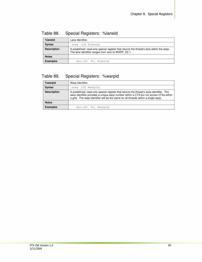
Chapter 8. Special Registers
PTX ISA Version 1.4 99 3/31/2009
Table 88. Special Registers: %laneid
%laneid Lane Identifier.
Syntax .sreg .u32 %laneid;
Description A predefined, read-only special register that returns the thread’s lane within the warp. The lane identifier ranges from zero to WARP_SZ-1.
Notes
Examples mov.u32 %r, %laneid;
Table 89. Special Registers: %warpid
%warpid Warp Identifier.
Syntax .sreg .u32 %warpid;
Description A predefined, read-only special register that returns the thread’s warp identifier. The warp identifier provides a unique warp number within a CTA but not across CTAs within a grid. The warp identifier will be the same for all threads within a single warp.
Notes
Examples mov.u32 %r, %warpid;
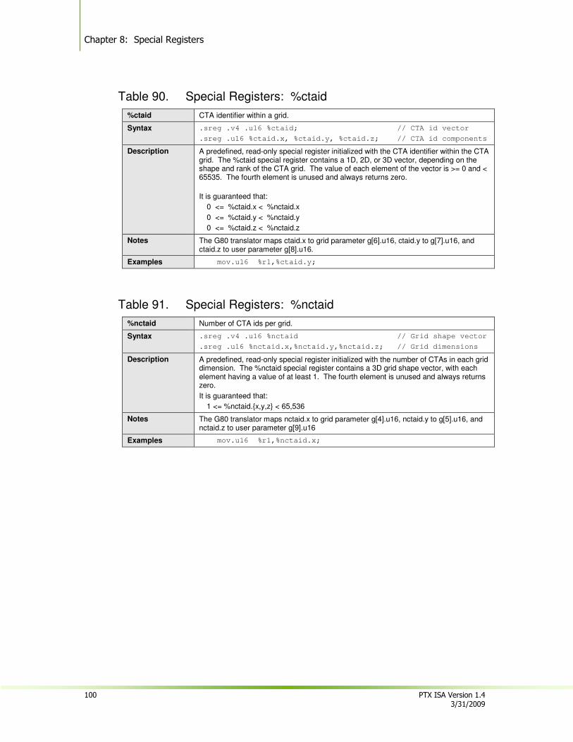
Chapter 8: Special Registers
100 PTX ISA Version 1.4 3/31/2009
Table 90. Special Registers: %ctaid
%ctaid CTA identifier within a grid.
Syntax .sreg .v4 .u16 %ctaid; // CTA id vector
.sreg .u16 %ctaid.x, %ctaid.y, %ctaid.z; // CTA id components
Description A predefined, read-only special register initialized with the CTA identifier within the CTA grid. The %ctaid special register contains a 1D, 2D, or 3D vector, depending on the shape and rank of the CTA grid. The value of each element of the vector is >= 0 and < 65535. The fourth element is unused and always returns zero.
It is guaranteed that:
0 <= %ctaid.x < %nctaid.x
0 <= %ctaid.y < %nctaid.y
0 <= %ctaid.z < %nctaid.z
Notes The G80 translator maps ctaid.x to grid parameter g[6].u16, ctaid.y to g[7].u16, and ctaid.z to user parameter g[8].u16.
Examples mov.u16 %r1,%ctaid.y;
Table 91. Special Registers: %nctaid
%nctaid Number of CTA ids per grid.
Syntax .sreg .v4 .u16 %nctaid // Grid shape vector
.sreg .u16 %nctaid.x,%nctaid.y,%nctaid.z; // Grid dimensions
Description A predefined, read-only special register initialized with the number of CTAs in each grid dimension. The %nctaid special register contains a 3D grid shape vector, with each element having a value of at least 1. The fourth element is unused and always returns zero.
It is guaranteed that:
1 <= %nctaid.{x,y,z} < 65,536
Notes The G80 translator maps nctaid.x to grid parameter g[4].u16, nctaid.y to g[5].u16, and nctaid.z to user parameter g[9].u16
Examples mov.u16 %r1,%nctaid.x;
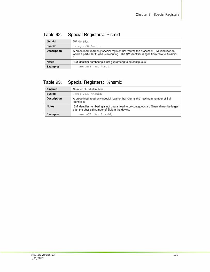
Chapter 8. Special Registers
PTX ISA Version 1.4 101 3/31/2009
Table 92. Special Registers: %smid
%smid SM identifier.
Syntax .sreg .u32 %smid;
Description A predefined, read-only special register that returns the processor (SM) identifier on which a particular thread is executing. The SM identifier ranges from zero to %nsmid-1.
Notes SM identifier numbering is not guaranteed to be contiguous.
Examples mov.u32 %r, %smid;
Table 93. Special Registers: %nsmid
%nsmid Number of SM identifiers.
Syntax .sreg .u32 %nsmid;
Description A predefined, read-only special register that returns the maximum number of SM identifiers.
Notes SM identifier numbering is not guaranteed to be contiguous, so %nsmid may be larger than the physical number of SMs in the device.
Examples mov.u32 %r, %nsmid;

Chapter 8: Special Registers
102 PTX ISA Version 1.4 3/31/2009
Table 94. Special Registers: %gridid
%gridid Grid identifier.
Syntax .sreg .u32 %gridid; // initialized when the grid is launched
Description A predefined, read-only special register initialized with the per-grid temporal grid identifier. The %gridid is used by debuggers to distinguish CTAs within concurrent (small) CTA grids.
During execution, repeated launches of programs may occur, where each launch starts a grid-of-CTAs. This variable provides the temporal grid launch number for this context.
Notes The driver assigns a counting sequential gridid to each grid launched.
The G80 translator implements a 16-bit gridid which is mapped to grid parameter g[0].u16.
Examples mov.u32 %r, %gridid;
Table 95. Special Registers: %clock
%clock A predefined, read-only 32-bit unsigned cycle counter.
Syntax
Description Special register %clock is an unsigned 32-bit read-only cycle counter that wraps silently.
Notes
Examples mov.u32 r1,%clock;
Table 96. Special Registers: %pm0, %pm1, %pm2, %pm3
%pm0, …, %pm3 Performance monitoring counters.
Syntax
Description Special registers %pm0, %pm1, %pm2, and %pm3 are unsigned 32-bit read-only performance monitor counters. Their behavior is currently undefined.
Notes
Examples mov.u32 r1,%pm0;
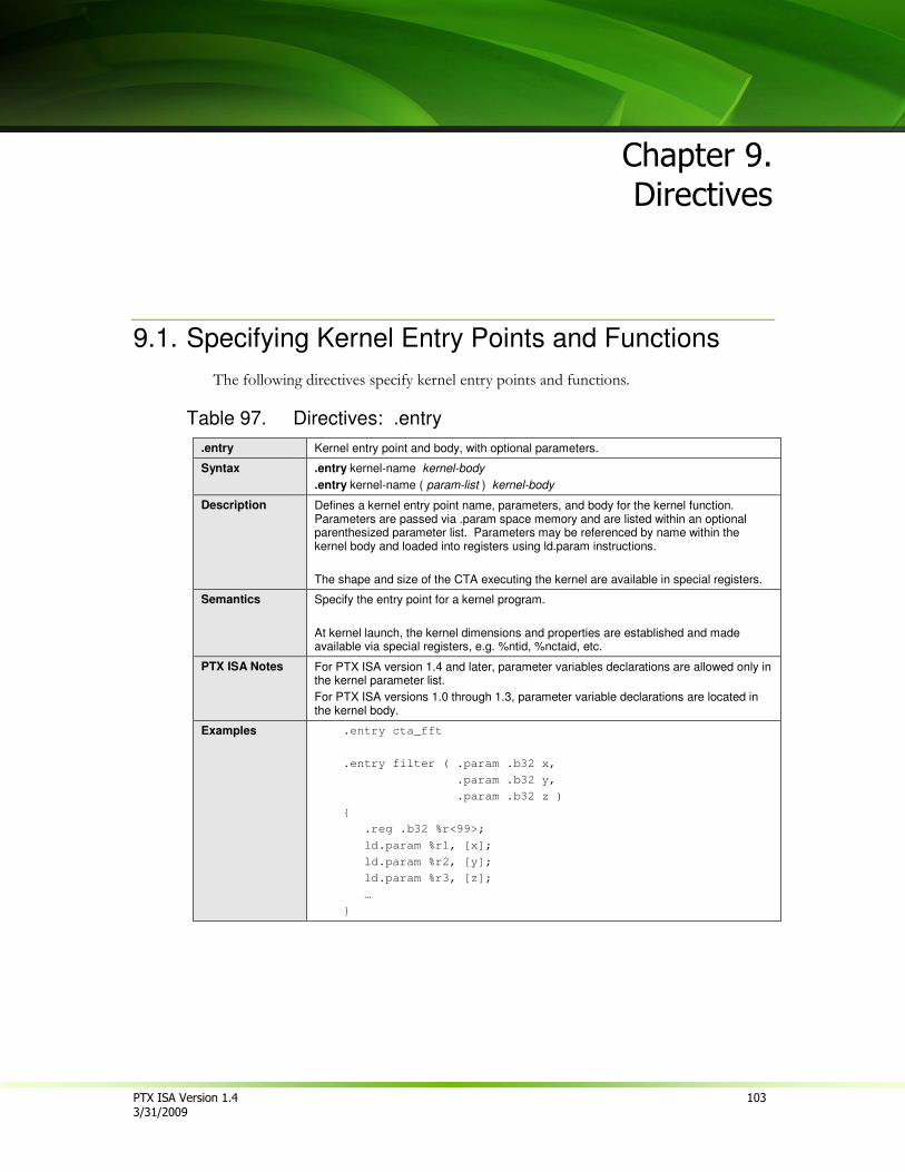
PTX ISA Version 1.4 103 3/31/2009
Chapter 9.
Directives
9.1. Specifying Kernel Entry Points and Functions
The following directives specify kernel entry points and functions.
Table 97. Directives: .entry
.entry Kernel entry point and body, with optional parameters.
Syntax .entry kernel-name kernel-body
.entry kernel-name ( param-list ) kernel-body
Description Defines a kernel entry point name, parameters, and body for the kernel function. Parameters are passed via .param space memory and are listed within an optional parenthesized parameter list. Parameters may be referenced by name within the kernel body and loaded into registers using ld.param instructions.
The shape and size of the CTA executing the kernel are available in special registers.
Semantics Specify the entry point for a kernel program.
At kernel launch, the kernel dimensions and properties are established and made available via special registers, e.g. %ntid, %nctaid, etc.
PTX ISA Notes For PTX ISA version 1.4 and later, parameter variables declarations are allowed only in the kernel parameter list.
For PTX ISA versions 1.0 through 1.3, parameter variable declarations are located in the kernel body.
Examples .entry cta_fft
.entry filter ( .param .b32 x,
.param .b32 y,
.param .b32 z )
{
.reg .b32 %r<99>;
ld.param %r1, [x];
ld.param %r2, [y];
ld.param %r3, [z];
…
}
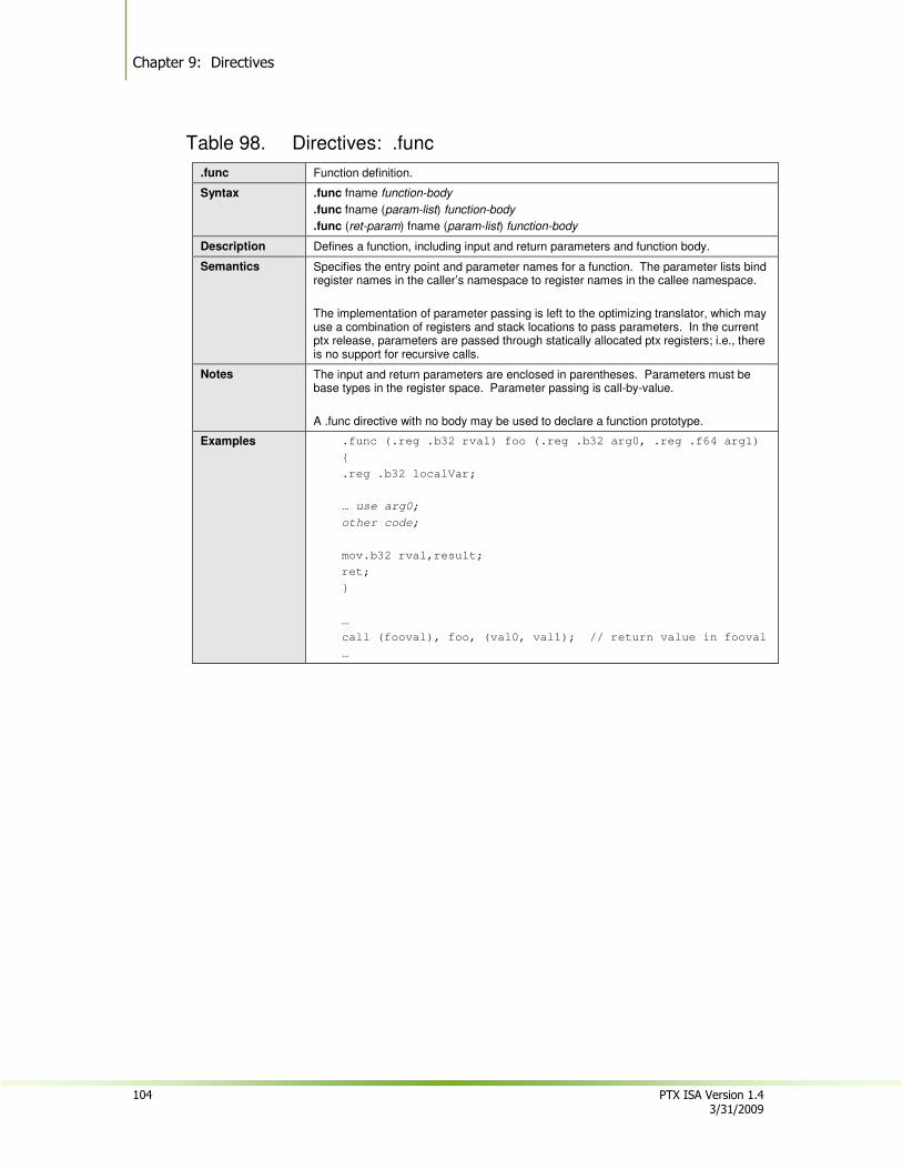
Chapter 9: Directives
104 PTX ISA Version 1.4 3/31/2009
Table 98. Directives: .func
.func Function definition.
Syntax .func fname function-body
.func fname (param-list) function-body
.func (ret-param) fname (param-list) function-body
Description Defines a function, including input and return parameters and function body.
Semantics Specifies the entry point and parameter names for a function. The parameter lists bind register names in the caller’s namespace to register names in the callee namespace.
The implementation of parameter passing is left to the optimizing translator, which may use a combination of registers and stack locations to pass parameters. In the current ptx release, parameters are passed through statically allocated ptx registers; i.e., there is no support for recursive calls.
Notes The input and return parameters are enclosed in parentheses. Parameters must be base types in the register space. Parameter passing is call-by-value.
A .func directive with no body may be used to declare a function prototype.
Examples .func (.reg .b32 rval) foo (.reg .b32 arg0, .reg .f64 arg1)
{
.reg .b32 localVar;
… use arg0;
other code;
mov.b32 rval,result;
ret;
}
…
call (fooval), foo, (val0, val1); // return value in fooval
…
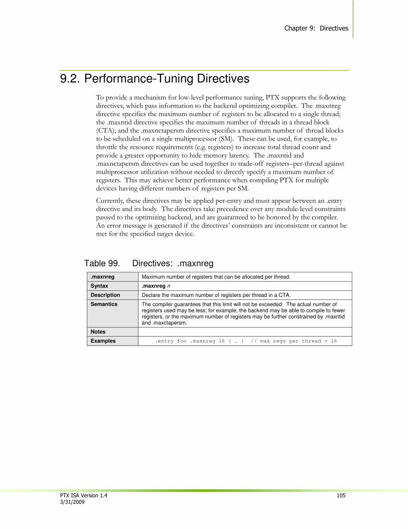
Chapter 9: Directives
PTX ISA Version 1.4 105 3/31/2009
9.2. Performance-Tuning Directives
To provide a mechanism for low-level performance tuning, PTX supports the following directives, which pass information to the backend optimizing compiler. The .maxnreg directive specifies the maximum number of registers to be allocated to a single thread; the .maxntid directive specifies the maximum number of threads in a thread block (CTA); and the .maxnctapersm directive specifies a maximum number of thread blocks to be scheduled on a single multiprocessor (SM). These can be used, for example, to throttle the resource requirements (e.g. registers) to increase total thread count and provide a greater opportunity to hide memory latency. The .maxntid and .maxnctapersm directives can be used together to trade-off registers–per-thread against multiprocessor utilization without needed to directly specify a maximum number of registers. This may achieve better performance when compiling PTX for multiple devices having different numbers of registers per SM.
Currently, these directives may be applied per-entry and must appear between an .entry directive and its body. The directives take precedence over any module-level constraints passed to the optimizing backend, and are guaranteed to be honored by the compiler. An error message is generated if the directives’ constraints are inconsistent or cannot be met for the specified target device.
Table 99. Directives: .maxnreg
.maxnreg Maximum number of registers that can be allocated per thread.
Syntax .maxnreg n
Description Declare the maximum number of registers per thread in a CTA.
Semantics The compiler guarantees that this limit will not be exceeded. The actual number of registers used may be less; for example, the backend may be able to compile to fewer registers, or the maximum number of registers may be further constrained by .maxntid and .maxctapersm.
Notes
Examples .entry foo .maxnreg 16 { … } // max regs per thread = 16

Chapter 9: Directives
106 PTX ISA Version 1.4 3/31/2009
Table 100. Directives: .maxntid
.maxntid Maximum number of threads in thread block (CTA).
Syntax .maxntid nx
.maxntid nx, ny
.maxntid nx, ny, nz
Description Declare the maximum number of threads in the thread block (CTA). This maximum is specified by giving the maximum extent of each dimention of the 1D, 2D, or 3D CTA. The maximum number of threads is the product of the maximum extent in each dimension.
Semantics The maximum size of each CTA dimension is guaranteed not to be exceeded in any invocation of the kernel in which this directive appears. Exceeding any of these limits results in a runtime error or kernel launch failure.
Notes
Examples .entry foo .maxntid 256 { … } // max threads = 256
.entry bar .maxntid 16,16,4 { … } // max threads = 1024
Table 101. Directives: .maxnctapersm
.maxnctapersm Maximum number of CTAs per SM.
Syntax .maxnctapersm ncta
.maxnctapersm target:ncta
.maxnctapersm target1:ncta1, target2:ncta2, …
Description Declare the maximum number of CTAs from the kernel’s grid that may be mapped to a single multiprocessor (SM). If no target architecture is specified, the directive applies to the target architecture specified by the preceeding .target directive. Multiple target-specific limits may be listed in the directive. Note that the directive’s constraints are always target-specific.
Semantics The maximum number of CTAs that may be mapped to a single SM is guaranteed not to be exceeded in any invocation of the kernel in which this directive appears.
Notes Optimizations based on .maxnctapersm generally need .maxntid to be specified as well.
Examples .entry foo .maxntid 256 .maxnctapersm 4 { … }
.entry bar .maxntid 256 .maxnctapersm sm_10:4,sm_13:8 { … }
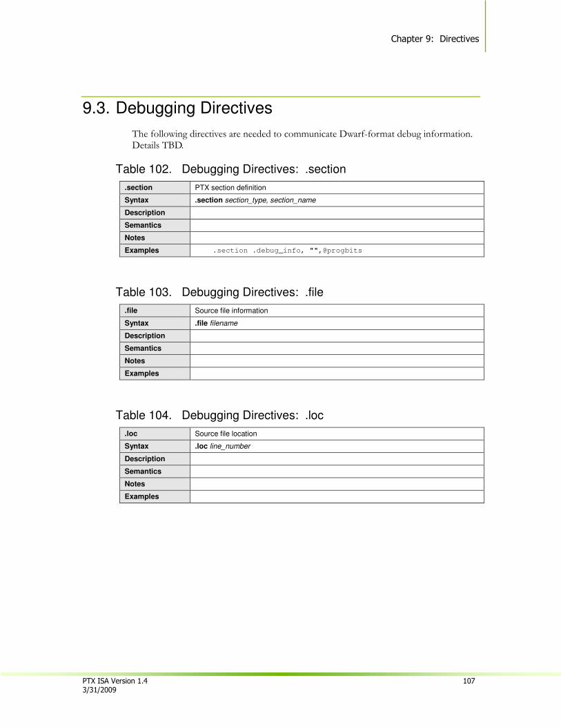
Chapter 9: Directives
PTX ISA Version 1.4 107 3/31/2009
9.3. Debugging Directives
The following directives are needed to communicate Dwarf-format debug information. Details TBD.
Table 102. Debugging Directives: .section
.section PTX section definition
Syntax .section section_type, section_name
Description
Semantics
Notes
Examples .section .debug_info, "",@progbits
Table 103. Debugging Directives: .file
.file Source file information
Syntax .file filename
Description
Semantics
Notes
Examples
Table 104. Debugging Directives: .loc
.loc Source file location
Syntax .loc line_number
Description
Semantics
Notes
Examples
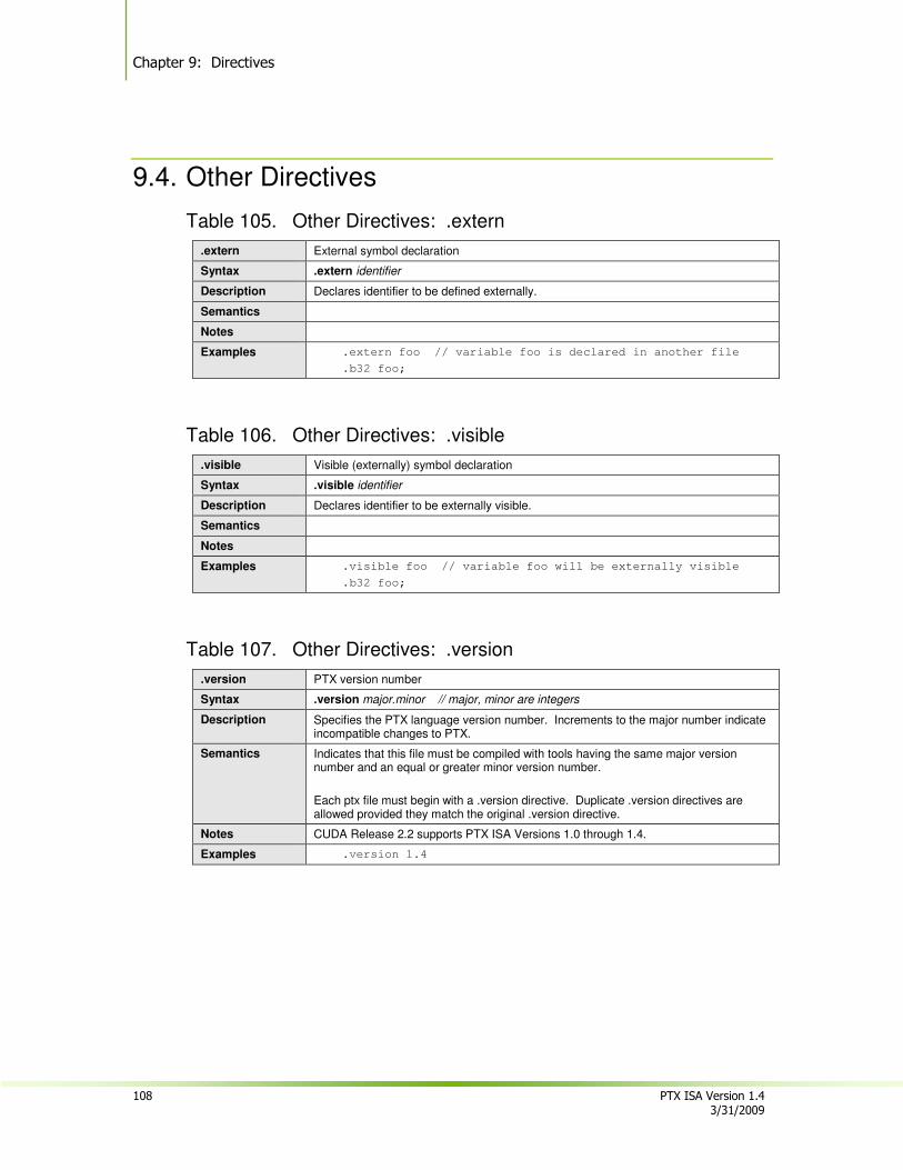
Chapter 9: Directives
108 PTX ISA Version 1.4 3/31/2009
9.4. Other Directives
Table 105. Other Directives: .extern
.extern External symbol declaration
Syntax .extern identifier
Description Declares identifier to be defined externally.
Semantics
Notes
Examples .extern foo // variable foo is declared in another file
.b32 foo;
Table 106. Other Directives: .visible
.visible Visible (externally) symbol declaration
Syntax .visible identifier
Description Declares identifier to be externally visible.
Semantics
Notes
Examples .visible foo // variable foo will be externally visible
.b32 foo;
Table 107. Other Directives: .version
.version PTX version number
Syntax .version major.minor // major, minor are integers
Description Specifies the PTX language version number. Increments to the major number indicate incompatible changes to PTX.
Semantics Indicates that this file must be compiled with tools having the same major version number and an equal or greater minor version number.
Each ptx file must begin with a .version directive. Duplicate .version directives are allowed provided they match the original .version directive.
Notes CUDA Release 2.2 supports PTX ISA Versions 1.0 through 1.4.
Examples .version 1.4
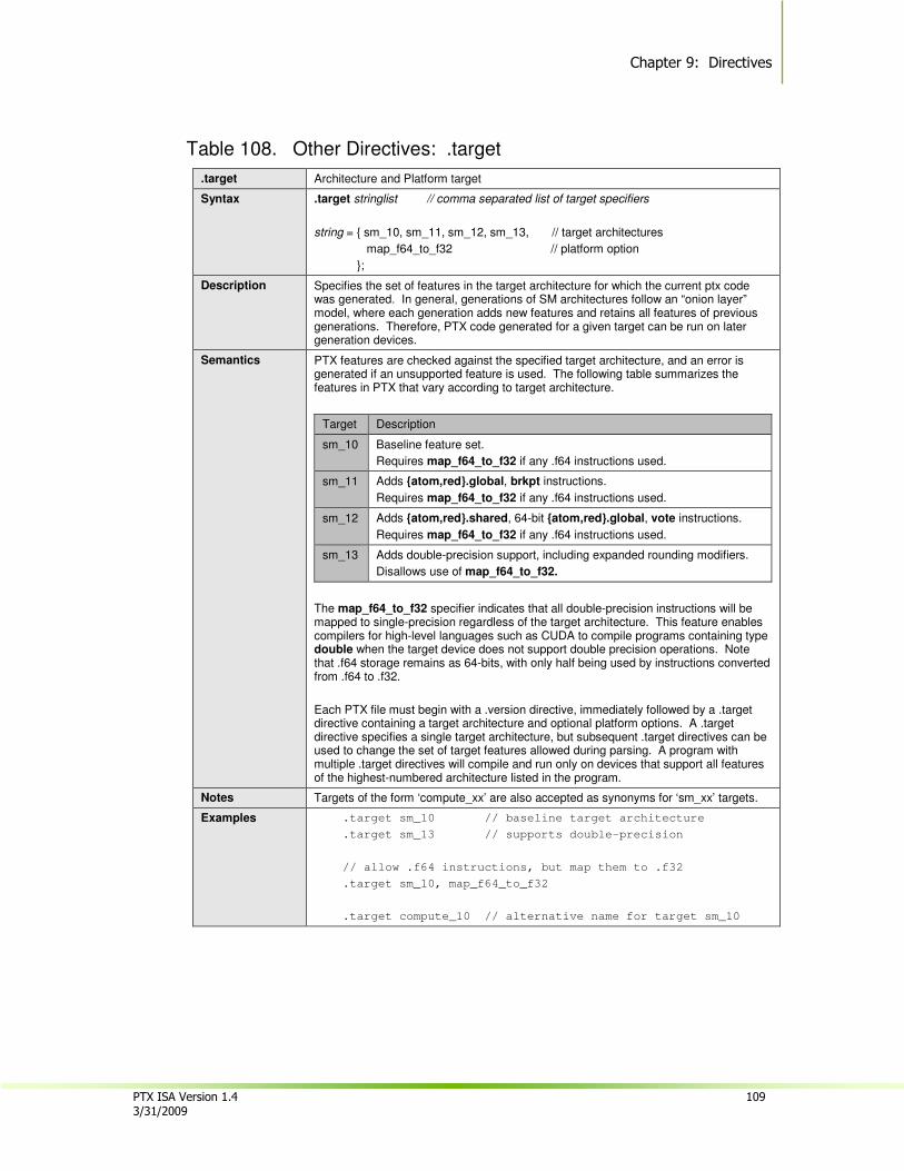
Chapter 9: Directives
PTX ISA Version 1.4 109 3/31/2009
Table 108. Other Directives: .target
.target Architecture and Platform target
Syntax .target stringlist // comma separated list of target specifiers
string = { sm_10, sm_11, sm_12, sm_13, // target architectures
map_f64_to_f32 // platform option
};
Description Specifies the set of features in the target architecture for which the current ptx code was generated. In general, generations of SM architectures follow an “onion layer” model, where each generation adds new features and retains all features of previous generations. Therefore, PTX code generated for a given target can be run on later generation devices.
Semantics PTX features are checked against the specified target architecture, and an error is generated if an unsupported feature is used. The following table summarizes the features in PTX that vary according to target architecture.
Target Description
sm_10 Baseline feature set.
Requires map_f64_to_f32 if any .f64 instructions used.
sm_11 Adds {atom,red}.global, brkpt instructions.
Requires map_f64_to_f32 if any .f64 instructions used.
sm_12 Adds {atom,red}.shared, 64-bit {atom,red}.global, vote instructions.
Requires map_f64_to_f32 if any .f64 instructions used.
sm_13 Adds double-precision support, including expanded rounding modifiers.
Disallows use of map_f64_to_f32.
The map_f64_to_f32 specifier indicates that all double-precision instructions will be mapped to single-precision regardless of the target architecture. This feature enables compilers for high-level languages such as CUDA to compile programs containing type double when the target device does not support double precision operations. Note that .f64 storage remains as 64-bits, with only half being used by instructions converted from .f64 to .f32.
Each PTX file must begin with a .version directive, immediately followed by a .target directive containing a target architecture and optional platform options. A .target directive specifies a single target architecture, but subsequent .target directives can be used to change the set of target features allowed during parsing. A program with multiple .target directives will compile and run only on devices that support all features of the highest-numbered architecture listed in the program.
Notes Targets of the form ‘compute_xx’ are also accepted as synonyms for ‘sm_xx’ targets.
Examples .target sm_10 // baseline target architecture
.target sm_13 // supports double-precision
// allow .f64 instructions, but map them to .f32
.target sm_10, map_f64_to_f32
.target compute_10 // alternative name for target sm_10
Chapter 9: Directives
110 PTX ISA Version 1.4 3/31/2009
This page is blank.
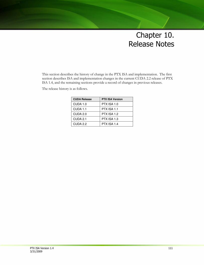
PTX ISA Version 1.4 111 3/31/2009
Chapter 10.
Release Notes
This section describes the history of change in the PTX ISA and implementation. The first section describes ISA and implementation changes in the current CUDA 2.2 release of PTX ISA 1.4, and the remaining sections provide a record of changes in previous releases.
The release history is as follows.
CUDA Release PTX ISA Version
CUDA 1.0 PTX ISA 1.0
CUDA 1.1 PTX ISA 1.1
CUDA 2.0 PTX ISA 1.2
CUDA 2.1 PTX ISA 1.3
CUDA 2.2 PTX ISA 1.4
Chapter 10: Release Notes
112 PTX ISA Version 1.4 3/31/2009
10.1. Changes in Version 1.4
10.1.1. New Features
Instruction membar has been added.
Instruction pmevent has been added to trigger an event associated with one of the performance monitor counters.
Floating-point instructions have the following changes from PTX ISA 1.3:
• A flush-to-zero modifier (.ftz) has been added to single-precision instructions add, sub, mul, mad, div, rcp, sqrt, rsqrt, sin, cos, lg2, ex2, abs, neg, min, max, cvt, set, setp, and slct. This modifier gives explicit indication that subnormal inputs are treated as zero and subnormal results are flushed to zero. This modifier is optional, and single-precision instructions default to .ftz.
• Floating-point instructions that compute an approximate result are now identified with the modifier .approx. This modifier is required for instructions {div, rcp, sqrt, rsqrt, sin, cos, lg2, ex2}.f32 and rsqrt.f64. In legacy PTX code, these instructions (with no .approx modifier) are understood to be the approximate version
• A full-range divide (div.full) has been added. This divide scales operands when necessary to provide a fast, approximate, full-range divide.
• A double-precision fused multiply-add instruction (fma.f64) has been added. This instruction is a synonym for mad.f64.
• A rounding modifier is required in cases where IEEE 754 compliant rounding is supported. In particular, {mad, div, rcp, sqrt}.f64 now require an explicit rounding modifier. For div, rcp, and sqrt, only round-to-nearest-even rounding is supported. In legacy PTX code, {mad, div, rcp, sqrt}.f64 will default to {div, rcp, sqrt}.rn.f64.
• Optional saturation (.sat) has been removed from div.f32.
Kernel parameters are now required to be defined within a parenthesized parameter list as part of the .entry directive.
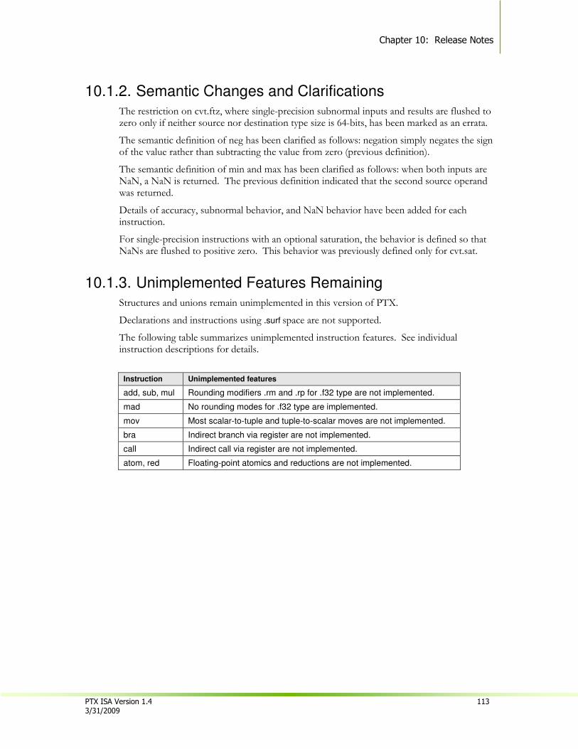
Chapter 10: Release Notes
PTX ISA Version 1.4 113 3/31/2009
10.1.2. Semantic Changes and Clarifications
The restriction on cvt.ftz, where single-precision subnormal inputs and results are flushed to zero only if neither source nor destination type size is 64-bits, has been marked as an errata.
The semantic definition of neg has been clarified as follows: negation simply negates the sign of the value rather than subtracting the value from zero (previous definition).
The semantic definition of min and max has been clarified as follows: when both inputs are NaN, a NaN is returned. The previous definition indicated that the second source operand was returned.
Details of accuracy, subnormal behavior, and NaN behavior have been added for each instruction.
For single-precision instructions with an optional saturation, the behavior is defined so that NaNs are flushed to positive zero. This behavior was previously defined only for cvt.sat.
10.1.3. Unimplemented Features Remaining
Structures and unions remain unimplemented in this version of PTX.
Declarations and instructions using .surf space are not supported.
The following table summarizes unimplemented instruction features. See individual instruction descriptions for details.
Instruction Unimplemented features
add, sub, mul Rounding modifiers .rm and .rp for .f32 type are not implemented.
mad No rounding modes for .f32 type are implemented.
mov Most scalar-to-tuple and tuple-to-scalar moves are not implemented.
bra Indirect branch via register are not implemented.
call Indirect call via register are not implemented.
atom, red Floating-point atomics and reductions are not implemented.
Chapter 10: Release Notes
114 PTX ISA Version 1.4 3/31/2009
10.2. Changes in Version 1.3
10.2.1. New Features
Instruction subc has been added, and 32-bit integer sub has been extended to read and write a carry flag in order to support efficient extended-precision subtraction in PTX.
Additional special registers have been added to give more information about kernel execution parameters, and to support performance monitor counters. The new special registers are %laneid, %warped, %smid, %nsmid, and %pm0..%pm3.
Vector types are now supported.
Performance-tuning directives .maxnreg, .maxntid, and .maxnctapersm have been added.
Instructions div.{u64,s64} and rem.{u64,s64} are now implemented.
10.2.2. Semantic Changes and Clarifications The behavior of floating-point saturation in cvt.sat has been changed so that NaN inputs are flushed to positive zero; previously, NaN inputs were preserved.
Vector-scalar and scalar-vector moves have been documented. These were partially implemented in previous releases but not documented.
The type of %gridid has been changed from .u16 to .u32. This special register is implemented in the parser but driver support to properly initialize the register remains unimplemented.
Predicate variables are restricted to scalar registers.
For convenience, ld, st, and cvt instructions permit source and destination data operands to be wider than the instruction-type size, so that narrow values may be loaded, stored, and converted using regular-width registers. This feature was partially supported in prior releases but was undocumented. See Section 7.4.1 for a detailed description of this feature.
10.2.3. Unimplemented or Unused Features Removed The unimplemented div.wide and rem.wide instructions have been removed.
The unused .tex[n] directive for binding a texture to a specific resource has been removed. All texture resources are allocated by the compiler.
10.2.4. Syntax Restrictions
The .param declarations are restricted to .entry scope.
The .tex declarations are restricted to module (global) scope.
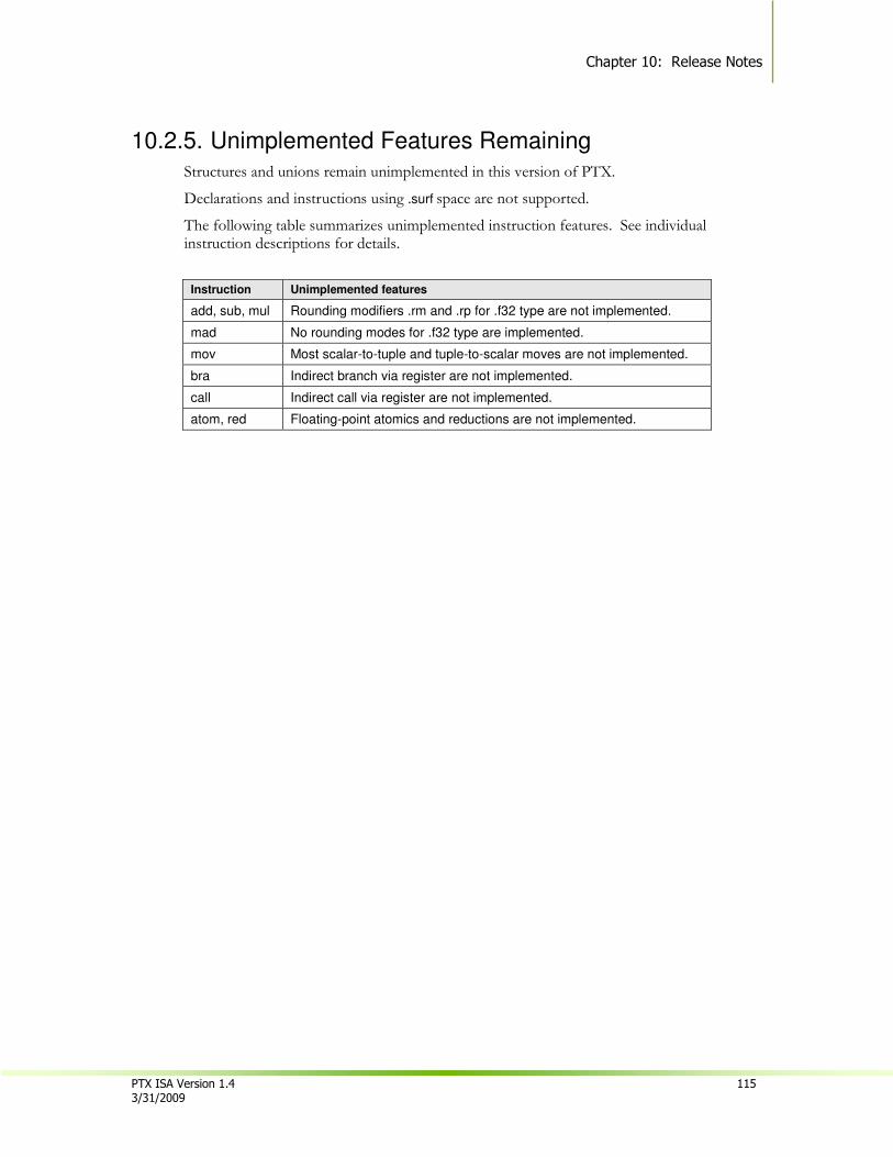
Chapter 10: Release Notes
PTX ISA Version 1.4 115 3/31/2009
10.2.5. Unimplemented Features Remaining
Structures and unions remain unimplemented in this version of PTX.
Declarations and instructions using .surf space are not supported.
The following table summarizes unimplemented instruction features. See individual instruction descriptions for details.
Instruction Unimplemented features
add, sub, mul Rounding modifiers .rm and .rp for .f32 type are not implemented.
mad No rounding modes for .f32 type are implemented.
mov Most scalar-to-tuple and tuple-to-scalar moves are not implemented.
bra Indirect branch via register are not implemented.
call Indirect call via register are not implemented.
atom, red Floating-point atomics and reductions are not implemented.
Chapter 10: Release Notes
116 PTX ISA Version 1.4 3/31/2009
10.3. Changes in Versions 1.2
10.3.1. New Features
An addc instruction has been added, and 32-bit integer add has been extended to read and write a carry flag in order to support efficient extended-precision addition in PTX.
A separate red instruction for computing atomic reductions where the intermediate results are not required has been added.
Support for constant expressions has been added to PTX.
A compact syntax for defining a set of variables having a common prefix and sequentially numbered suffixes has been added.
10.3.2. Semantic Changes and Clarifications Memory instructions in PTX require naturally aligned addresses, where the address is a multiple of the access size. This requirement was previously undocumented.
The tex instruction always generates a four-element result. This requirement was previously undocumented. The list of instruction types for tex has been restricted to supported types. Previous implementations required a four-element coordinate vector; the current implementation only requires that the coordinate vector contain at least as many elements as the instruction’s geometry.
Vector types no longer allow three-element vectors, i.e., .v3 has been removed from the language. Previous versions of PTX used .v3 as the implicit type for special registers. These registers are now defined as four-element vectors (e.g. .v4.u16), with the fourth element being unused.
Vectors are now restricted to a maximum overall length of 128 bits, which precludes four-element vectors with 64-bit elements, e.g. .v4.f64.
The shl and shr instruction descriptions have been updated to indicate that the shift amount operand is interpreted as an unsigned value regardless of the instruction type.
Floating-point instructions add, sub, and mul default to round-to-nearest-even behavior. This allows better optimization in the default case, such as folding mul+add into a single fused-multiply add instruction on the target device.
Details of precision and rounding have been added for instruction mad. The 32-bit mad is currently implemented with less precision than a fused multiply-add, and future implementations reserve the right to map mad.f32 to fused multiply-add.
10.3.3. Unimplemented or Unused Features Removed sad.f32 and sad.f64 have been removed from PTX Version 1.2. While these where implemented in previous releases, they were unused by the CUDA compiler and were not well-characterized with respect to precision and rounding behavior.
Chapter 10: Release Notes
PTX ISA Version 1.4 117 3/31/2009
The unimplemented frc instruction has been removed from the ISA.
The .entry directive no longer supports explicit CTA parameters. These were unimplemented.
The unimplemented .byte directive has been removed.
Unimplemented vector features such as vector element swizzling and vector-scalar conversions have been removed from the ISA.
10.3.4. Syntax Restrictions
Instructions ld, st, atom, red, and tex now require square brackets around the address expression. Previous versions of the ISA showed square brackets only for ld and st, and these were not required by the parser.
Numeric vector-element selectors (.0, .1, .2, and .3) have been removed. These were unimplemented in previous versions of the parser.
Variables of type .f16 no longer support initializations.
Constant banks have been removed. This feature was unimplemented.
The .tex declaration now requires a type of .u32 or .u64.
10.3.5. Unimplemented Features Remaining Vector types, structures, and unions remain unimplemented in this version of PTX.
Declarations and instructions using .surf space are not supported.
Instructions div.{u64,s64} and rem.{u64,s64} remain unimplemented.
Chapter 10: Release Notes
118 PTX ISA Version 1.4 3/31/2009
10.4. Changes in Version 1.1
This section describes changes in the PTX ISA and implementation between version 1.0 and version 1.1. The changes may be summarized as (1) addition of new features, (2) removal of unimplemented features and instructions from the ISA, (3) better specification of rounding modifiers, and (4) better specification of saturation behavior.
10.4.1. New Features Instructions ld and st now support a .volatile modifier. See the instruction descriptions in Chapter 7 for details.
10.4.2. Unimplemented Features Removed
PTX ISA version 1.0 contained a number of instructions and features that were unimplemented in the CUDA tools in release 1.0. Since these features were not implemented, their removal from PTX ISA version 1.1 does not create an incompatibility with any valid PTX version 1.0 code.
The vector instructions cross, dot, mag, and vred have been removed from PTX. These instructions were unimplemented in version 1.0.
Instructions extract, insert, membar, and nop were removed from the list of reserved PTX keywords shown in Table 2. The description of membar was removed from Chapter 7. These instructions were unimplemented in version 1.0.
Support for .f64 type in sin, cos, lg2, ex2, and frc has been removed from the ISA. These were unimplemented in version 1.0.
atom.{cas,exch} operations have been restricted to bitsize types. atom was unimplemented in PTX version 1.0.
10.4.3. Changes to Rounding Modifiers
PTX 1.0 did not fully specify rounding behavior for all instructions, nor did it define a default round behavior in cases where such defaults exist.
Rounding behavior not fully specified in PTX version 1.0 has been defined in version 1.1, with the following changes noted as errata for version 1.0:
• Instructions add, sub, and mul have round-to-nearest documented as their default rounding behavior.
• Instruction mad no longer supports a rounding modifier.
• sad and div no longer support a rounding modifier, although div is guaranteed to implement round-to-nearest-even by default.
• Rounding modifiers are now required in some cases and illegal in other cases for the cvt instruction (see description). Hand-written version 1.0 PTX code may exist that violates these new restrictions.
Chapter 10: Release Notes
PTX ISA Version 1.4 119 3/31/2009
10.4.4. Changes to Saturation
Saturation support has been removed from a number of instructions. None of these cases were used by the CUDA 1.0 compiler, and many were not implemented. These restrictions are compatible with PTX 1.0 code generated by the CUDA compiler tools.
• Integer saturation has been removed from instructions mul, mul24, mad.wide, mad.lo, mad24.lo, sad, div, and rem no longer support saturation.
• The cvt instruction supports saturation for both signed and unsigned integer types.
10.4.5. Unimplemented Features Remaining
In Release 1.1 of the PTX ISA Version 1,1, a number of features are not supported. This section summarizes the unsupported features.
Syntax restrictions
Predicate constant immediates are not supported.
Constant expressions are not supported.
State Spaces
Declarations and instructions using .surf space are not supported.
The constant space is restricted to a single bank. This may be written as .const or .const[0].
Variables and Operands
Vector declarations, initialization, and conversions are not supported.
Vector operands are not generally supported. The ld, st, and tex instructions do support limited use of vector operands written using the tuple notation.
Instructions
See individual instruction descriptions in Section 7.7 for restrictions of the current release.
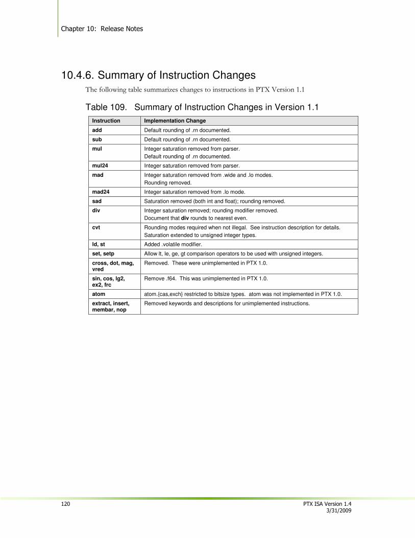
Chapter 10: Release Notes
120 PTX ISA Version 1.4 3/31/2009
10.4.6. Summary of Instruction Changes
The following table summarizes changes to instructions in PTX Version 1.1
Table 109. Summary of Instruction Changes in Version 1.1
Instruction Implementation Change
add Default rounding of .rn documented.
sub Default rounding of .rn documented.
mul Integer saturation removed from parser.
Default rounding of .rn documented.
mul24 Integer saturation removed from parser.
mad Integer saturation removed from .wide and .lo modes.
Rounding removed.
mad24 Integer saturation removed from .lo mode.
sad Saturation removed (both int and float); rounding removed.
div Integer saturation removed; rounding modifier removed.
Document that div rounds to nearest even.
cvt Rounding modes required when not illegal. See instruction description for details.
Saturation extended to unsigned integer types.
ld, st Added .volatile modifier.
set, setp Allow lt, le, ge, gt comparison operators to be used with unsigned integers.
cross, dot, mag, vred
Removed. These were unimplemented in PTX 1.0.
sin, cos, lg2, ex2, frc
Remove .f64. This was unimplemented in PTX 1.0.
atom atom.{cas,exch} restricted to bitsize types. atom was not implemented in PTX 1.0.
extract, insert, membar, nop
Removed keywords and descriptions for unimplemented instructions.
NVIDIA Corporation 2701 San Tomas Expressway
Santa Clara, CA 95050 www.nvidia.com
Notice
ALL NVIDIA DESIGN SPECIFICATIONS, REFERENCE BOARDS, FILES, DRAWINGS, DIAGNOSTICS, LISTS, AND OTHER DOCUMENTS (TOGETHER AND SEPARATELY, “MATERIALS”) ARE BEING PROVIDED “AS IS.” NVIDIA MAKES NO WARRANTIES, EXPRESSED, IMPLIED, STATUTORY, OR OTHERWISE WITH RESPECT TO THE MATERIALS, AND EXPRESSLY DISCLAIMS ALL IMPLIED WARRANTIES OF NONINFRINGEMENT, MERCHANTABILITY, AND FITNESS FOR A PARTICULAR PURPOSE.
Information furnished is believed to be accurate and reliable. However, NVIDIA Corporation assumes no responsibility for the consequences of use of such information or for any infringement of patents or other rights of third parties that may result from its use. No license is granted by implication or otherwise under any patent or patent rights of NVIDIA Corporation. Specifications mentioned in this publication are subject to change without notice. This publication supersedes and replaces all information previously supplied. NVIDIA Corporation products are not authorized for use as critical components in life support devices or systems without express written approval of NVIDIA Corporation.
Trademarks
NVIDIA and the NVIDIA logo are trademarks or registered trademarks of NVIDIA Corporation in the United States and other countries. Other company and product names may be trademarks of the respective companies with which they are associated.
Copyright
© 2009 NVIDIA Corporation. All rights reserved.