publishable activity report 3 9 2010 - vzlu.cz advanced structure of small gas turbine engine...
TRANSCRIPT

Publishable Final Activity Report – August 2010
CESAR Consortium © 2010 Public Document Page 1 of 98
Internal ref. no.:
Contract no: AIP5-CT-2006-030888
CESAR
Cost-Effective Small AiRcraft
Integrated Project Aeronautics Priority
Publishable Final Activity Report Reporting period 1st September 2006 – 28th February 2010
Prepared by: A. Coordinator - Karel Paiger, VZLU
B. PMC members - WP and Task leaders
Document control data Deliverable No. :
Revision: Final version Date of issue:
Author’s name: Karel Paiger / PMC members
Status: approved
PMC members: WP and Task
Leaders Status:
approved
Release status:
Start Date of CESAR: 1st September 2006 Duration: 42 Months
CESAR is coordinated by: VZLU - Vyzkumny a zkusebni letecky ustav, a.s.
This document has been produced by the CESAR consortium under FP6 of the EU.
Copyright and all other rights are reserved by the partners in the CESAR consortium.

Publishable Final Activity Report – August 2010
CESAR Consortium © 2010 Public Document Page 2 of 98
CONTENT 1. Executive Summary ................................................................................................................................ 3
1.1 Project summary ..................................................................................................................................... 3
1.2 General Project Objectives ...................................................................................................................... 4
1.3 Project Structure ...................................................................................................................................... 5
1.4 Cesar Consortium .................................................................................................................................... 7
2. Work performed, objectives reached ..................................................................................................... 8
2.1 High Fidelity Design Tools ‐ task 1.1 ........................................................................................................ 8
2.2 Advanced Wing ‐ task 1.2 ...................................................................................................................... 12
2.3 Flight Dynamics ‐ task 1.3 ..................................................................................................................... 16
2.4 Operational Loads ‐ task 2.1 ................................................................................................................. 20
2.5 New Design Approach to Advanced Airframe Structures ‐ task 2.2 ...................................................... 23
2.6 New strength evaluation methods of advanced airframe structure ‐ task 2.3 ..................................... 32
2.7 Smart structural health monitoring ‐ task 2.4 ....................................................................................... 35
2.8 Flutter Prevention for Small Aircraft ‐ task 2.5 ...................................................................................... 37
2.9 Advanced Structure of Small Gas Turbine Engine (IVCHENKO) ‐ task 3.1 ............................................. 48
2.10 Complex Power‐plant Control System (CP‐CS) ‐ task 3.2 ....................................................................... 53
2.11 Environmentally friendly propeller propulsion ‐ task 3.3 ...................................................................... 57
2.12 Cost effective actuation – task 4.1 ........................................................................................................ 61
2.13 Competitive technologies for air systems ‐ task 4.2 .............................................................................. 64
2.14 Integrated diagnostics and on condition maintenance ‐ task 4.3 ......................................................... 67
2.15 New Design and Development Concept ‐ task 5.1 ................................................................................. 70
2.16 Evaluation Platforms ‐ task 5.2 ............................................................................................................. 73
3. Plan for using and disseminating the knowledge ..................................................................................... 76
3.1 Exploitable knowledge and its use ........................................................................................................ 76
3.2 Dissemination of Knowledge ................................................................................................................. 77
3.3 Publication ............................................................................................................................................. 80
3.4 Protection of knowledge – patents ....................................................................................................... 84
4. Summary of technical achievements .................................................................................................... 85
5. Fulfilment of CESAR objectives ............................................................................................................. 93
6. Final conclusion ................................................................................................................................... 94
7. Annex 1 ‐ Plan for using and dissemination .......................................................................................... 95
8. Annex 2 ‐ List of Abbreviations ............................................................................................................. 96
Publishable Final Activity Report – August 2010
CESAR Consortium © 2010 Public Document Page 3 of 98
1. EXECUTIVE SUMMARY
1.1 Project summary
Project acronym: CESAR Project name: Cost-Effective Small AiRcraft
The project of 6th Framework Programme supported by European Commission Contract number: 30888
Number of participants: 39 organizations from 14 countries
Total budget (€): 33.7 million EC subsidy (€): 18.1 million More information: www.cesar-project.eu
CESAR focused on small-size commercial aircraft providing manufacturers with an enhanced ability needed to become fully competitive in the world market. The objective was to build up a new development concept for this aircraft category and to improve selected technologies enabling a significant reduction of the time-to-market and lowering the overall development, operation and maintenance costs, while considering safety, passenger comfort and environmental impact.
The project consisted of five RTD areas sufficiently covering the complexity of the aircraft design process, namely aerodynamic and structural design, propulsion integration, aircraft system optimisation and design integration aspects. In particular CESAR aimed at enhancing aerodynamic and structural design tools and structural evaluation methods. RTD work comprises development, validation and integration of design tools and methodologies to provide suitable environment for virtual aircraft simulation. Enhancement of design processes, knowledge management and collaboration tools was an essential part of the project.
Another important part of the project was technological development for aircraft subparts and systems. The CESAR provided technologies and knowledge for advanced wing, competitive and environmentally acceptable propulsion unit and new technologies for selected aircraft systems to reduce aircraft operating costs and improve safety.
The activities included the integration of the latest technologies already applied to large commercial aircraft and their modified economical use within the category of small-size commercial aircraft, e.g. cost effective actuation, complex power-plant control system, competitive technologies for air systems, structural health monitoring and on condition maintenance systems.
Validation was carried out on two levels: a) on the task level (hardware platforms), b) on the project level (two baseline a/c configurations for assessment and tradeoffs).

Publishable Final Activity Report – August 2010
CESAR Consortium © 2010 Public Document Page 4 of 98
1.2 General Project Objectives
- Time to market reduction by 2 years - Development cost reduction by 20% - Reduction of manufacturing and assembly costs by 16% - Propulsion unit efficiency and affordability - Optimization of selected aircraft systems
Time to market reduction by 2 years Nowadays it takes on average 6-7 years to design, develop and fully certify a small passenger aircraft. The goal of the CESAR project is to reduce development time necessary for this category of aircraft to 4 years (28% reduction). Such improvement can be done through the use of reliable and affordable design tools, mainly for aerodynamic and structural design and integrated software environment enabling virtual simulation of the aircraft.
Development cost reduction by 20% The development costs form part of the aircraft selling price. Using convenient and affordable design tools and methodologies, with straightforward applicability to project and knowledge management can bring significant effects in terms of development cost reduction. The goal of the CESAR project is to reduce development cost at least by 20%.
Reduction of manufacturing and assembly costs by 16% The production effectiveness depends on materials used and on particular production technologies, joining processes and on assembly itself. The majority of these production factors, related primarily to the airframe of the aircraft, are already determined at the early stages of the aircraft design. A distinct part of expenses is formed by power plant (20-30 %) and by other aircraft systems (15-30%) that are also addressed by the project. The goal of the CESAR project is to reduce assembly costs by 16%.
Propulsion unit efficiency and affordability Affordable turboprop engines powered of 200-400 kW are not available on the European market. The only option for today airplane manufacturers which need such power-plants is to buy them from the companies based in the North America. CESAR can give a real chance to change this nearly monopoly situation. The project will challenge technologies to reduce fuel consumption by 5 to 15 % employing modern propeller and engine control system. New propeller propulsion units can reduce noise emissions in the far field by 3 to 6 dB(A). The plan is also to reduce overall engine weight by 7-9%.
Optimization of selected aircraft systems HUMS (Health and Usage Monitoring System) customized for small airplane should reduce maintenance costs by 30 % and improve serviceability. New technologies based on electro-hydraulic and electromechanical actuation technologies (EHA, EMA) specifically tuned for small commercial aircraft can contribute to the aircraft weight reduction and operational cost-efficiency. Air systems are essential part of passenger’s comfort aboard an aircraft. For small airplanes such technologies must be low-weighted and very affordable. Reduction of air systems noise by 5 dB can improve passengers comfort in cabin and reduce even external noise emissions. CESAR seriously tries to cope with these issues.

Publishable Final Activity Report – August 2010
CESAR Consortium © 2010 Public Document Page 5 of 98
1.3 Project Structure
The project is structured into the five RTD work packages domains comprising 16 tasks in total. An extra work package is devoted to management and training.
Overall project structure

Publishable Final Activity Report – August 2010
CESAR Consortium © 2010 Public Document Page 6 of 98
WP1 - Aerodynamic Design The overall objective was to demonstrate the capability of modern CFD tools to enhance the aerodynamic design process for small commercial aircraft. The baseline reference configurations will be defined for the demonstration in a way to meet the needs of the involved airframers. In addition to the methods and tools aspect aerodynamic knowledge was provided in terms of design principles or advanced aerodynamics and e.g. airfoil catalogues, which are especially devoted to close gaps in existing databases. In a similar manner, aspects the potential of computational tools for flight dynamics and their use early in the design process was demonstrated and validated by corresponding tests. WP2 - Structural Design A wide range of activities related to airplane structure development, certification and maintenance process was symptomatic for this WP. The main objective of this WP was getting a tool that would increase the effectiveness of the future structure design and the certification project stage for small-size aircraft category. Thus the project impact would cover the whole complex of problems from pre-development analysis to effective maintenance. Rationale for task selection was the reduction of development and operational costs in tasks 2.1, 2.2, 2.3, 2.5 and diminishing safety and security concerns in task 2.4. WP3 - Propulsion Integration The program focused on engine and propulsive device architecture with respect to flight safety, payload economy and environmental stress. In the aero-thermodynamic portrait of the engine new technologies for high-speed small-size turbomachinery design were applied as high precision gearing, smart engine and integrated full electronic engine and propeller control system (Complex Power-plant Control System) and engine aero-acoustic optimisation of a complete propulsion unit. WP4 - Optimized Systems Activities in WP4 focused on three main targets: electro-hydraulic actuation, competitive technologies for air systems and integrated diagnostics and on-conditioning maintenance systems. Costs were the main issue for these tasks. New maintenance systems were supposed to bring significant reduction of the operational costs. However, strong reductions for development, manufacturing and assembly costs were also expected for all systems. WP5 - Design Concept Integration and Validation WP5 targeted on new design and development concept for small aircraft and on the evaluation of the technologies analysed in the WPs 1, 2, 3, and 4. The new design concept aimed to achieve time to market reduction through development of a modern architecture for the integrated design process tailored for the small commercial aircraft industry. The new development concept applied innovative techniques, such as “critical chain” and modern product lifecycle management tailored to the small aircraft industry, allowing to integrate people, information, processes, and business units to create an environment in which companies can develop, produce and support a product more efficiently (i.e. reduce time to market). The evaluation of technologies was driven by the defined top level aircraft requirements. Aircraft platforms were used for the trade-off analysis so that the benefits of the novel technologies were demonstrated on the overall aircraft level.

Publishable Final Activity Report – August 2010
CESAR Consortium © 2010 Public Document Page 7 of 98
1.4 Cesar Consortium
List of participants
Nr Organisation Participant short name Country
1 Výzkumný a zkušební letecký ústav, a.s. VZLU Czech Republic
2 Aero Vodochody a.s. AERO Czech Republic
3 AIT ‐ Austrian Institute of Technology GbmH ARC Austria
4 Centre de Recherche en Aéronautique, ASBL CENAERO Belgium
5 Centro Italiano Ricerche Aerospaziali ScpA CIRA Italy
6 Deutsches Zentrum für Luft‐ und Raumfahrt e.V. DLR Germany
7 EADS Deutschland GmbH EADS ‐CRC Germany
8 EUROCOPTER S.A.S. EUROCOPTER France
9 EVEKTOR, spol. s r. o. EVEKTOR Czech Republic
10 Swedish Defence Research Agency FOI Sweden
11 AERNNOVA Engineering Solutions, S.A., AERNNOVA Spain
13 HELLENIC AEROSPACE INDUSTRY S.A. HAI Greece
14 VR Group, a.s. HEXAGON HGS Czech Republic
15 Institutul National de Cercetari Aerospatiale "Elie Carafoli" INCAS Romania
16 Instytut Lotnictwa ‐ Institute of Aviation IoA Poland
17 IVCHENKO PROGRESS SE IVCHENKO Ukraine
18 Jihlavan a.s. JIHLAVAN Czech Republic
19 JIHOSTROJ a.s. JIHOSTROJ Czech Republic
20 Liebherr Aerospace Toulouse SAS LIEBHERR LTS France
21 Materials Engineering Research Laboratory Ltd MERL UK
22 MESIT pristroje spol. s r.o. MESIT Czech Republic
23 Stichting Nationaal Lucht‐ en Ruimtevaartlaboratorium NLR Netherlands
24 OFFICE NATIONAL D'ETUDES ET DE RECHERCHES AEROSPATIALES ONERA France
25 První brněnská strojírna Velká Bíteš, a.s. PBS Czech Republic
26 PIAGGIO AERO INDUSTRIES S.p.A. PIAGGIO AERO Italy
27 Polskie Zaklady Lotnicze Sp. z o.o. PZL Poland
28 Swerea SICOMP AB SICOMP Sweden
29 DAHER SOCATA SOCATA France
30 SPEEL PRAHA, Ltd. SPEEL Czech Republic
31 Svenska Rotor Maskiner AB SRM Sweden
32 Technofan SA TECHNOFAN TF France
33 TURBOMECA TURBOMECA (TM) France
34 UNIS, a.s. UNIS Czech Republic
35 The University of Manchester UoM U. K.
36 Brno University of Technology VUT Brno Czech Republic
37 RWTH Aachen University RWTH‐AC Germany
38 Université de Liège ULg Belgium
39 Technische Universität München, Institute of Energy Systems IES Germany
40 Univesity of Patras LMS‐UPATRAS Greece

Publishable Final Activity Report – August 2010
CESAR Consortium © 2010 Public Document Page 8 of 98
2. WORK PERFORMED, OBJECTIVES REACHED
2.1 High Fidelity Design Tools - task 1.1
Lead company: INCAS Task Leader: Catalin NAE List of Subtasks Task 1.1 was subdivided into two subtasks:
- subtask 1.1.1 – Baseline models definitions and CFD tools evaluation - subtask 1.1.2 – Tools adaptation in order to meet specific needs of AeroDesign for
small 1 a/c
Figure 1: Task 1.1 time chart
Task objectives The aim of this WP is to provide high level technical support and tools in order to:
• define suitable reference configurations to demonstrate an improvement with respect to current state of the art and given requirements;
• select configurations that have a development potential in small a/c category; • provide a highly efficient package of tools for aerodynamic analysis, tailored for the
specific requirements of small a/c • adapt and improve specific tools to be used for aerodynamic analysis and global
design process • enable tools integration in WP5.1 in the proposed IDS

Publishable Final Activity Report – August 2010
CESAR Consortium © 2010 Public Document Page 9 of 98
Achieved results and their contributions to the general measurable project objectives: Major results from Task 1.1 are related to the baseline reference configurations definitions, tools analysis and methodology development:
• Complete optimised reference configurations for two small a/c categories (twin propeller, unpressurized low speed a/c and pressurised small business jet)
• Efficient tools for complete aero-design and analysis including guidelines for their usage.
• Evaluation and assessment of key analysis tools and methodology for development of a new generation of small a/c
• Specific tools tailored to the needs and requirements of small a/c category, as part of an integrated design environment that meets industry specifications;
• Direct output in standard engineering formats for other WPs of the CESAR project with respect to reference configurations for small a/c for multidisciplinary analysis;
Figure 2: Baseline reference configurations definition
A number of tools have been evaluated for reliable analysis, using the reference configurations and/or specific information, as follows:
High lift analysis tools VLM tool for global analysis Global optimization tool for 3D configurations Special tool for modelling and evaluation of propeller effects

Publishable Final Activity Report – August 2010
CESAR Consortium © 2010 Public Document Page 10 of 98
A complete picture for the global set of tools and their integration is presented below.
Figure 3: Tools evaluated in T1.1
Figure 4: Adapted tools for CESAR project
Following this activity, existing tools at partners enable achievement of following performance data with respect to initial goals:
Flight dynamics analysis/ experiment assess.: 2 days (compared to 1 week before) Full 3D flow analysis/ CFD evaluation : 1 week (compared to 2 weeks before) Configuration evaluation : 1 week (compared to 4 weeks before)

Publishable Final Activity Report – August 2010
CESAR Consortium © 2010 Public Document Page 11 of 98
Task 1.1 contributions of technical results to the general project objectives are integrated in the table below:
Table 1: Task 1.1 contribution to CESAR project objectives

Publishable Final Activity Report – August 2010
CESAR Consortium © 2010 Public Document Page 12 of 98
2.2 Advanced Wing - task 1.2
Lead company: DLR Task Leader: Arne Seitz List of Subtasks Task 1.2 was subdivided into three subtasks:
- subtask 1.2.1 - Airfoil sections and high-lift devices - subtask 1.2.2 - Wing concept optimisation - subtask 1.2.3 - Methodology for contamination assessment
Task objectives The effort of the aerodynamic design of an aircraft is rapidly increasing. In particular the use of modern CFD methods requires exceedingly excellent knowledge and experience and thus a high measure of time need. On the other hand these modern CFD methods allow analysing geometries of high complexity with a high level of reliability. Objectives of task 1.2 were
- to provide methods, tools, data and experiences, which allow accelerating the aerodynamic design process,
- to demonstrate that by means of powerful CFD methods in combination with optimisation strategies superior designs with considerably improved performance can be generated,
- to give a higher degree of safety in the early design phase in particular with respect to flow separation and icing by utilizing very accurate high fidelity CFD methods.
Achieved results and their contributions to the general measurable project objectives: The contribution of task 1.2 to the general project objectives are based on the improvements in the aerodynamic design process and may be summarized as follows:
Task 1.2 contributed to the general project objective: Time to market and development cost reduction
by using CFD and optimization tools even in early design stages allowing for more and quicker parameter variations with highly reliable results
by replacing costly and time consuming wind tunnel tests in intermediate design stages through performance evaluation by CFD tools
by avoiding costly flight tests for post treatment of deficiencies (e.g. fixing of unacceptable stall behaviour & minimizing areas with separated flow)
Task 1.2 contributed to the general project objective: Enhancement of fuel efficiency
by using advanced airfoil sections and wing concepts that have the potential to reduce the total aircraft drag

Publishable Final Activity Report – August 2010
CESAR Consortium © 2010 Public Document Page 13 of 98
Subtask 1.2.1 Airfoil Sections and high-lift devices
Lead company: VZLU Subtask Leader: Marian Zabloudil
Subtask objectives: For the typical Reynolds-/Mach number range of small A/C (Re = 2 – 15 * 106, M = 0.2 –0.8) only very few airfoil geometries are published including their aerodynamic characteristics. Thus, the main objective of subtask 1.2.1 was the development of a number of airfoil sections which are adapted to the flow conditions of small commercial aircraft creating an airfoil data base. In particular, the goal was not only to provide conventional turbulent designs but also airfoil sections with a considerably high amount of laminar boundary layer flow allowing for low drag wing designs.
Figure 5: CFD results (lift curve, pitching moment coefficient and drag polar) in cruise condition and low speed clean configuration for AC2-laminar airfoil section
Subtask 1.2.2 Wing concept optimisation
Lead company: DLR Subtask Leader: Arne Seitz
Subtask objectives Subtask 1.2.2 was aimed at an optimised wing design. Therefore, an important objective was to establish design rules for general wing design by providing example designs for typical needs of small commercial aircraft. To experience and to demonstrate the advantages of modern high fidelity methods was another important objective of this subtask. The comparison with results of pre-design methods, frequently used for small aircraft design to date, allows quantifying the advantages of the use of high fidelity methods.
CE-DLR-AS-ROOT-13.6CE-DLR-AS-ROOT-13.6

Publishable Final Activity Report – August 2010
CESAR Consortium © 2010 Public Document Page 14 of 98
Several wing concept optimizations for CESAR reference aircrafts AC1 and AC2 were performed based on the outcome of subtask 1.2.1.
Figure 6: Wind tunnel model of AC2 with optimized turbulent wing
Exemplarily for the CFD work performed, the results for a laminar wing design for AC2 are presented in Figure 7, showing the benefit of advanced laminar flow technology for small commercial aircraft.
Figure 7: Wing cp-distributions at design point and drag polar in cruise condition for AC2-laminar. A total drag reduction of 30 counts is predicted.

Publishable Final Activity Report – August 2010
CESAR Consortium © 2010 Public Document Page 15 of 98
Subtask 1.2.3 Methodologies for contamination assessment
Lead company: CIRA Subtask Leader: Giuseppe Mingione
Subtask objectives: Wing concept optimisation The objective of this task is the investigation of airfoil surface imperfection and its impact on airfoil performances. Two different types of contamination have been investigated:
Contamination due to ice accretion; Contamination due to manufacturing imperfections
Most critical for flight safety are the different types of ice accretion with its corresponding degradation of flight performance and behavior, while for a laminar wing the reliable knowledge of the critical size of manufacturing imperfections at which the extent of laminar flow will be reduced is indispensable.
Figure 8: Ice shapes tested in VZLU wind tunnel (left) and IR-image of test article with simulated imperfections to study impact on transition of laminar to turbulent boundary layer flow

Publishable Final Activity Report – August 2010
CESAR Consortium © 2010 Public Document Page 16 of 98
2.3 Flight Dynamics - task 1.3
Lead company: EADS-CRC Task Leader: Olaf Heinzinger
List of Tasks Task 1.3 was subdivided into two subtasks:
- subtask 1.3.1 – Development of the advanced flight dynamics computation tool - subtask 1.3.2 – Flight dynamics testing procedures and validation
Flight Dynamics in Aircraft Design Flight Dynamical considerations are an integral part of modern Aircraft design. The effects noticeable to the pilot and passengers include the general behaviour as well as Stability and Control and Flying Qualities / Handling Qualities. When designing for appropriate performance, such integral parameters as the aircraft dimensioning, mass distribution and the control system are affected.
By developing a chain of tools as performed in CESAR, the aim is to move aircraft development from a mechanical iterative approach towards simulative methods, which reduce the amount of real life testing.
Figure 9: Design processes
The tool chain basically consists of a simulation tool that is connected to analysis modules (Flying Qualities, Stability and Control). An integral part is the estimation of the model behaviour, i.e. the aircraft modelling. Multiple methods have been studied in the course of this project and were evaluated.

Publishable Final Activity Report – August 2010
CESAR Consortium © 2010 Public Document Page 17 of 98
The following graph depicts the relation of the performed tasks within CESAR:
The Simulation tool hosts the detailed mathematical description of the aircraft kinematics and dynamics as well as the generic models of typical aircraft subsystems (aerodynamic, propulsion, flight control system, actuators and sensors…). The Output of the simulation process will be used for:
• Flight dynamics and handling qualities analysis • Integrated analysis with parametric design methodologies • Compute system responses efficiently for each design alternative
In order to enter the aircraft specific characteristics of the respective type, the model parameters need to be determined. Multiple methods can be used such as: Panel Methods, Handbook Methods, CFD methods. Also model parameter estimation from flight test data can be and was conducted.
During the CESAR project the aircraft Aerovodochody Ae270 and Evektor Ev55 have been analysed.
For estimation of model parameters from flight test data the methodology roughly is as follows: Optimize (aerodynamic) model parameters in a way so that control inputs into a dynamic model (simulation) lead to the same resulting states as they would in the measured flight test data.
FCL
GASA = GASF
GASA = GASF
AS
GASW GASHT
GASVT
8906270
10869
13387
281
8
183
918
X
Y
ZX
ZY
X
X
Z
Y
XX
Z Z
X
Y
X
Y
Y
Y
YZ
Z
Z
Simulation Analysis/ Results
A/C-Modelling
A/C Modelling - Handbook Methods - Panel Method - Wind Tunnel Data
6 dof-Aircraft
Systems
Flight Test Data based: - scale aircraft - subscale aircraft
Model Identification
Figure 10: The relation of performed tasks within CESAR
Figure 11:

Publishable Final Activity Report – August 2010
CESAR Consortium © 2010 Public Document Page 18 of 98
In order to come to complete parameter sets, the parameter identification needs to be conducted for various points in the flight envelope and for multiple configurations. The illustration below shows the fit of the initial model vs. flight-test data and the model after optimisation vs. flight test.
The aircraft have to be equipped with instrumentation accordingly. The parameters to record in the CESAR project were latitude, longitude, geodetic altitude, velocities, accelerations, Euler angles, angular velocities, Angle of Attack, Angle of Sideslip, pressures and temperatures.
Figure 13:
In addition to the scale models, flight test also was conducted with a subscale model that needed to be dimensioned dynamically similar in order to guarantee dynamic equivalence. For this purpose, the Evektor EV-55 was chosen and built. (MTOW = 25kg).
Initial Model
after 10 iterations
0 200 400 600 800 1000 1200 1400 1600 1800 2000-0.4
-0.3
-0.2
-0.1
0
0.1
0.2
0.3
0 200 400 600 800 1000 1200 1400 1600 1800 2000-0.4
-0.3
-0.2
-0.1
0
0.1
0.2
0.3
Figure 12: Fit of the initial model vs. flight-test data and model after optimisation vs. flight test

Publishable Final Activity Report – August 2010
CESAR Consortium © 2010 Public Document Page 19 of 98
Figure 14:
Following the estimation of model parameters, the analysis of Flying- and Handling-Qualities was conducted. The tool developed within the CESAR project includes analysis of HQ and FQ requirements as specified in CS-23 as well as the guidelines as specified in MIL-F-8785C and MIL-STD-1797.
As an enclosing framework, an optimization tool was designed. Its task is to optimize flight dynamically most relevant parameters for an optimum behaviour with respect to CS23 requirements. These include Static stability, Control to trim, Stick force/g as well as the behaviour in the different dynamic modes (Phygoid mode, Short period mode, Dutch roll mode, Spiral mode, Roll performance). Also the Flight path stability as well as the Dynamic stability has been considered.
The degrees of freedom in the aircraft parameters were the dimensioning of control surface, their allocation and the control authority allocation
The multicriteria optimisation tool utilizes Global non convex optimisation, stochastic search methods (Genetic algorithms and Differential Evolution). Within the task, the applicability of the tool chain has been satisfactorily demonstrated.
Processing
SIMULATION
Data PROCESSIN
G
HQ Req. {criteria]
Conformity
Flight TEST
WitnessFile
Load DATA
Work DATA
Witness & Results
Constitutive
paramete
Default HQ
ResultsDATA
ResultsDATA
Default Final
HQ Options
Graphical Witness
File
DATA GENERATION
Final HQOptions
Graphical
WitnessFile
Flight REGIME
Steady Flight
Steady Flight VARIABLES
Unsteady
Fli ht
Linear ANALYS
Graphical
Figure 15:

Publishable Final Activity Report – August 2010
CESAR Consortium © 2010 Public Document Page 20 of 98
2.4 Operational Loads - task 2.1
Lead Company: EVEKTOR Task Leader: Robert Falta List of subtask Task 2.1 was subdivided into four subtasks:
- subtask 2.1.1 - System architecture - subtask 2.1.2 - Aeroplane database, solvers - subtask 2.1.3 - Post processing - subtask 2.1.4 - Validation, manuals - subtask 2.1.5 - Fatigue tools
Task 2.1 partners developed within the CESAR project a complex tool solving following fields of the operational loads problematic
• CS 23 internal loads distribution on aircraft parts, • dynamic loads occurring during landing impact, • aerodynamic load distribution on aircraft, • fatigue safe-life calculation, • preparation of load for fatigue tests.
The complex tool is formed by five tools
Figure 16:
The airplane database implemented in the tool contains following data inputs: • geometry data, • aerodynamic data, • mass distribution data, • mass configuration data, • propulsion data, • load cases definition.

Publishable Final Activity Report – August 2010
CESAR Consortium © 2010 Public Document Page 21 of 98
Work progress in the task The task was divided into five subtasks with respect to the development process. Work started in Subtask 2.1.1 System architecture by research among aircraft companies producing small aircrafts or providing aircraft development. Twelve companies were interviewed by T2.1 partners. With respect of the research results the system architecture was defined. Work continued in Subtask 2.1.2 Aeroplane database, Solvers where the structure of the Input database was defined. Partners developed and programmed solvers for their tools. Functionality was presented to T2.1 partners at the task meeting. For better coordination of tools aimed on fatigue a new Subtask 2.1.5 Fatigue tools was defined. After finishing the solvers, work continued in Subtask 2.1.3 Postprocessing by the development of postprocessing modules. Final work was done in Subtask 2.1.4 Validation, manuals. All partners developing a tool prepared user's and theoretic manuals, testing versions of the developed tools and training for testing partners which was presented during the three training workshops. The results from testing were collected by PIAGGIO in the final report. NLR compared load spectra used by fatigue tools with other sources and EVEKTOR validated the ALAN tool solver by flight test both with satisfactory results.

Publishable Final Activity Report – August 2010
CESAR Consortium © 2010 Public Document Page 22 of 98
Figure 17: Some views of the developed tools

Publishable Final Activity Report – August 2010
CESAR Consortium © 2010 Public Document Page 23 of 98
2.5 New Design Approach to Advanced Airframe Structures - task 2.2
Lead company: Piaggio Aero Industries Task Leader: Massimiliano Bertino List of Subtasks Task 2.2 was subdivided into three subtasks:
- subtask 2.2.1 – Metallic Structures - Window surround - subtask 2.2.2 – Composite Structures – Wing box - subtask 2.2.3 – Composite Structures – Fuselage structure
Task objectives Development of new design approaches aimed to the realization of advanced airframe structures for small aircraft and leading to a cost effective manufacturing suitable for this class of aircraft.
To achieve this goal, both metallic and composite technologies will be investigated in order to exploit the potential expressed by the most promising emerging techniques like as Fiber Placement and Liquid Infusion Techniques for composites and Friction Stir Welding for aluminium.
These technologies shall enable the sustainable growth of the small aircraft industry bringing to them some advantages already experimented on large aircraft and leading to a significant cost and time-to-market reduction for new aircraft, as called by The European Vision 2020. A machined/forged window frame welded by means of Friction Stir on a fuselage panel will be the metallic item.
A composite wing with spar and ribs co-bonded will be produced allowing the investigation of the joints and the full-scale test.
A fuselage roof designed as a single skinned laminate with reinforcement beams will be a composite demonstrator of the technology.
The realization of simplified reduced scale components to optimize the design, the manufacturing and the integration shall be considered for composites. Subtask: 2.2.1 – Metallic Structures - Window surround Subtask leader - company: EADS Deutschland GmbH Subtask leader - name: Juergen Silvanus Sub-Task objectives: In this subtask a metallic item realized by welding a machined window frame on a curved fuselage panel will be designed, developed and fabricated.

Publishable Final Activity Report – August 2010
CESAR Consortium © 2010 Public Document Page 24 of 98
This will allow investigating several critical aspects related to each step of the design and manufacturing process and in particular to perform a weight and cost assessment between the welded and the classical riveted solution.
In addition to the main component development a number of activities were objective of this period, the following: • Investigation of dissimilar joints • Trade-off study on tool orientation on non linear path welds with 6-axis-tilt-arm robotic • Surface protection development • Manufacturing of Window frame and surround skin, • Welding of the window assembly. • NDI • Repair scenario In subtask 2.2.1 the activities on metallic structures have an emphasis on robotic Friction-Stir-Welding (FSW). The application of interest has been defined by partner Piaggio Aero and is the joint between a window frame and the surrounding skin panel.
The objective is to substitute the riveted overlap geometry by a FSWelded butt joint configuration. Avoiding the overlap means a smaller flange of the window frame part and further advantages in durability and corrosion aspects.
Piaggio Aero provided two sets of window frames and skin panels in 3-D geometry. According to the geometrical needs EADS has designed and manufactured a suitable clamping jig and also a DeltaN welding tool that allows to get access to the joint line which is near the window frame stiffening inner ring, see Figure 18.
Figure 18: Individually designed DeltaN FSW tool with extra long shaft for access to the joint path directly next to the frame stiffening inner ring

Publishable Final Activity Report – August 2010
CESAR Consortium © 2010 Public Document Page 25 of 98
The determination of the welding parameters and for the fine-tuning of the robotics weld path line a bead-on-plate-weld on has been performed and used for optimisations
The final steps were the two real-component welds which have been performed successfully.
The main technical result achieved of the subtask 2.2.1 activities are like follows: 1. It has been shown that an 6-axis-articulated arm- robot is suitable to perform the
dissimilar welds in a 3-D-geometrical configuration.
2. The DeltaN FSW tool concept makes the process more robust because the tool position does not only depend on the force control but is further defined by the surface real geometrical shape. DeltaN reduces the welding distortion because of the resulting nearly fully symmetrical cross section. A further reduction of distortion is possible by changing the weld path line from a circular one to two half-circular welds for generating a higher degree of symmetry.
3. It has been discussed and agreed that the most attractive strategy to deal with the end hole is to position the end-hole in an external area that will be machined by milling after finishing the welding process.
4. Two welded-window-frames-to-skin exist and will be used by Piaggio Aero for further investigations, Figure 19
Figure 19: Window-Frame welded to skin – the endhole is positioned outside the circular weld path lines in the skin area

Publishable Final Activity Report – August 2010
CESAR Consortium © 2010 Public Document Page 26 of 98
Figure 20: Window-Frame welded to skin
Achieved results and their contributions to the general measurable project objectives The use of friction stir welding allows a number of advantages respect the traditional assemblies using metallic fastener. A detailed study has been performed with the following synthetic results:
• Weight saving: 11% • Fastener number saving: 100% • Cost saving (preliminary): 30%
A detailed study on the contributions of this sub-task to measurable project objectives is showed in the D.2.2.1-4 Subtask: 2.2.2 – Composite Structures – Wing box Subtask leader - company: NLR Subtask leader - name: Ronald Klomp – de Boer Subtask objectives: In this subtask a part of the composite wing box will be developed. From the trade-off on manufacturing process and geometry, results that the multispar concept and the automatic fiber placement are the best choices. The multispar wing box with co-bonded spars will be assembled with RTM ribs.
A comparison between classical machined and riveted wing box will be carried out in order to perform a weight and cost assessment and to individuate the critical aspects related to both hybrid and full-composite wings. The investigation of critical areas and/or innovative shapes will be performed through the design and manufacturing of reduced scale components.

Publishable Final Activity Report – August 2010
CESAR Consortium © 2010 Public Document Page 27 of 98
The activities that were objectives of the period are the following:
Detailed analysis Final drawings Coupon test
Manufacturing of the skin and spar by AFP machine
Manufacturing of the RTM Ribs
Realization of the forward wing
NDT
Repair consideration
A number of design activities have been developed. • Generating sub concepts based on AFP as production method • Combination of subconcepts selected for detailed design • AFP specific issues reported to minimize design iterations between NLR as
manufacturer and Piaggio as designer • General composite design practices agreed
At the same time a number of activities have been performed to optimize the design: • FEM Analysis and Dimensioning (HAI) • Spar strength evaluation test (MERL) • Coupon tests
1. Composite Design Allowable (IOA) 2. Impact Resistance and Damage Tolerance of Wing Skin Laminate (MERL) 3. Evaluation of Adhesively Bonded Joints of Wing Box Material (MERL)
Figure 21: Fiber placement machine with skin mould

Publishable Final Activity Report – August 2010
CESAR Consortium © 2010 Public Document Page 28 of 98
Figure 22: Upper Skin in front of autoclave after cure and cured Middle Spar
Figure 23: Load tree on the wing box
Achieved results and their contributions to the general measurable project objectives The manufacture of the items and their analysis has showed the following main results compared to the actual metallic architecture:
The weight saving is: 24 % The part number saving is: 22% The Hi-Lok number saving is: 45% The cost saving with composite architecture is: 30 % (to be confirmed)
A detailed study on the contributions of this sub-task to measurable project objectives is showed in the D.2.2.2-12

Publishable Final Activity Report – August 2010
CESAR Consortium © 2010 Public Document Page 29 of 98
Sub-Task: 2.2.3 – Composite Structures – Fuselage structure Subtask leader - company: EVEKTOR Subtask leader - name: Martin Drsticka Sub-Task objectives: In this subtask a top central fuselage part of a 5-7 pax unpressurised aircraft was realized with composite material. Modern low cost out-of-autoclave materials, tools, manufacturing procedures and design methods were used. This item will demonstrate the capability of the chosen technique for the small aircraft industry and will be the starting point for a weight and cost assessment.
The activities that were the objective of the period are the following (EVEKTOR, SICOMP): • Design studies • Detailed analysis • Final drawings • Tool design and manufacture • Manufacturing of coupons for allowables • Manufacturing of the roof • NDT • Repair consideration
A number of design activities have been developed (EVEKTOR, SICOMP): • Choice of material and process • Study of rehometric behaviour of the resin system • Vacuum Infusion technique limits – Mould filling strategy • Weave placement strategy – Study of the overlap and joint • Design of the components – Lay-UP Sequence
At the same time a number of activities have been performed to optimize the design: • FEM Analysis and Dimensioning for crash load condition(EVEKTOR)
Roof Front Pillars tests manufactured with different technologies by SICOMP (Vacuum Infusion and Pre-Preg)
• Coupon tests 1. Composite Design Allowable (IOA) 2. Impact Resistance and Damage Tolerance of Fuselage Shell (MERL) 3. Adhesively Bonded Joints Evaluation (MERL)

Publishable Final Activity Report – August 2010
CESAR Consortium © 2010 Public Document Page 30 of 98
Figure 24: Lay-up of the roof
Figure 25: Set-up of the roof for the out-of-autoclave cure at SICOMP
Figure 26: Completed roof

Publishable Final Activity Report – August 2010
CESAR Consortium © 2010 Public Document Page 31 of 98
Achieved results and their contributions to the general measurable project objectives It was not especially studied but under the saving of tools cost and under the number of jigs is expected of about 30% of time to market reduction.
For information see numbers of parts and jigs for both design solutions:
Aluminium roof 63 parts Composite roof 5 composite parts bonded together
8 metal parts (are installed into the composite roof) Jigs No. For aluminium roof 50 (+3 jigs could varied in serial production depending
on technology) Jigs No. For composite roof 5 Expected time to market reduction: 30%
Cost
Detailed analysis of the cost was described in a special deliverable (SICOMP): D2.2.3-6 Manufacturing Cost of the Fuselage Cost of the current design: Aluminium roof 6585 Euro (Note. Cost per one roof)
Expected savings: Prepreg – Carbon (prototype technology) 4410 Euro 23% save Prepreg- Carbon (with Maximum save of weight and with the best serial technology) 3572 Euro 46% save Weight Aluminium roof: 10.2 kg Target composite roof weight: 10 kg Prepreg Carbon Prototype Roof 3D model weighting 11.7 kg
Measured weight of the roof before cutting out (i.e. including the cutting waste) 14 kg Expected waste material is of about 2-2,5kg, so with serial technology and with serial tools is the target weight reachable. Expected is the same weight of serial product or saving of 3%.

Publishable Final Activity Report – August 2010
CESAR Consortium © 2010 Public Document Page 32 of 98
2.6 New strength evaluation methods of advanced airframe structure - task 2.3
Lead company: VZLU Task Leader: Josef Jironc List of Subtasks Task 2.3 was subdivided into two subtasks:
- subtask 2.3.1 - New experimental approaches - subtask 2.3.2 - New analytical approaches
Task objectives • Creation of several test methods and novel element tests mainly for composite coupon
testing • Development of a new structure loading system • Validation of new NDE techniques used in strength testing process • Development of fast and detailed pre-processing Finite Element tools able to allow the
creation of enhanced and detailed numerical models of aircraft components and sub-components
• Development of pre-processing Finite Element tools able to allow the creation of connection between non-coincident meshes
• Development of residual strength methods concerning: o Determination of impact damage tolerance in complex composite
structures o Buckling and post-buckling calculations o Fracture mechanics modeling.
• Support of other Tasks in the frame of above mentioned activities (T2.2 and T2.4) Achieved results and their contributions to the general measurable project objectives: Subtask 2.3.1: New experimental approaches • Loading system weight reduction + reduction of balancing masses – about 10 – 30% =
raw material cost reduction • Repeated using of rubber block segments (3-times at minimum) = NRC cost reduction
about 5 – 15 %
Figure 27: Loading system on elevator

Publishable Final Activity Report – August 2010
CESAR Consortium © 2010 Public Document Page 33 of 98
• Time reduction of failure area identification (about 10 – 20%) using Acoustic Emission technique during strength testing + real time structure health monitoring
Figure 28: Correlation of Structural Health Monitoring of growing fatigue crack by acoustic emission method (dots) and traditional visual inspections (line)
• Damage tolerance design methodology = potential reduction in weight, increase in safety
by considering and understanding the effect of potential defects Subtask 2.3.2: New analytical approaches • E-Buck system analysing load carrying capacity of thin shell structures
Figure 29
• FTA - Flexion twist anisotropy – buckling approach = 10 – 15% time reduction in
comparison to standard practice
0
10
20
30
40
0 20 000 40 000 60 000 80 000 100 000 120 000Life [cycle]
To
tal
Cra
ck L
eng
th [
mm
]
"A" crack length
"B" crack length
"C" crack length
"A" localisation
"B" localisation
"C" localisation
original artificial notch
sensor distance
effective range

Publishable Final Activity Report – August 2010
CESAR Consortium © 2010 Public Document Page 34 of 98
Figure 30
• FAST FEM MODEL DEVELOPMENT - The tool was implemented based on the APDL
programming language, which allows the application of parameters, vectors, arrays etc. that can also be manipulated with a series of commands similar to FORTRAN programming.
Figure 31
Another functionality, in the process of creating the geometric entities that comprise the panel and specify the composite lay-up, is that the code automatically calculates the lamina stepping at the stiffener/skin attachment areas.
Buckling out-of-plane deflexion form (with the typical trapezoidal shape) of the simply curved panel due to the flexural/twist anisotropy

Publishable Final Activity Report – August 2010
CESAR Consortium © 2010 Public Document Page 35 of 98
2.7 Smart structural health monitoring - task 2.4
Lead company: AERNNOVA Task Leader: Valerijan Cokonaj List of Subtasks Task 2.4 was subdivided into four subtasks:
- subtask 2.4.1 - Systems Definition - subtask 2.4.2 - Systems Analysis - subtask 2.4.3 - Specimen Design and Fabrication - subtask 2.4.4 - Systems Testing and Results Analysis
Task objectives: • Definition of prerequisites for development a reliable structural health monitoring systems • Development of software tools and damage detection algorithms • Development and test verification of new SHM transducers • Development of analytical tools for evaluation of fatigue effects on remaining life and
critical areas Achieved results and their contributions to the general measurable project objectives: Subtask 2.4.1: Systems Definition • Selected the most promising SHM technologies • Identified best future applications scenarios with SHM systems on board Subtask 2.4.2: Systems Analysis • Developed new fatigue tools and autonomous fatigue recorder verified
Figure 32: Autonomous fatigue recorder
Figure 33: AFLR software tools developed
Subtask 2.4.3: Specimen Design and Fabrication • Damage detection algorithms and tools developed • New SHM transducers was developed and successfully lab-tested

Publishable Final Activity Report – August 2010
CESAR Consortium © 2010 Public Document Page 36 of 98
Figure 34: FGC panel during simultaneous SHM and mechanic
load testing Figure 35: Demonstration of damage detection on FGC panels with
ARCAEDA SHM system
Subtask 2.4.4: Systems Testing and Results Analysis • Different SHM algorithms for different SHM technologies were developed, software and
hardware implemented, tested in simulated aerospace service conditions (temperature, humidity, vibration, noise, loading) and verified for damage detectability
• Tested performance of SHM systems in flight on small a/c • Evaluated damage detection performance of developed SHM technologies
Figure 36: FGC panel during simultaneous SHM and temperature/mechanic load testing
Figure 37: Flight testing of damage detection performance with 3 different SHM systems
Time to market reduction (in manufacturing phase & during certification testing) Preliminary introduction of predictive and on-condition maintenance at aircraft level Prerequisites for implementation of reductions of scheduled maintenance Prerequisites accomplished for reduced of direct maintenance costs Reduction of assembly costs Enhancement of aircraft safety Prerequisites accomplished for future mass reduction of future composite structures

Publishable Final Activity Report – August 2010
CESAR Consortium © 2010 Public Document Page 37 of 98
2.8 Flutter Prevention for Small Aircraft - task 2.5
Lead company: DLR Task Leader: Martin Rippl List of subtasks Task 2.5 was subdivided into two subtasks:
- subtask 2.5.1 – Flutter analysis - subtask 2.5.2 – Improved Flutter certification process
Task objectives: Aeroelastic instabilities like flutter are self-excited oscillations which may occur when an aircraft exceeds a certain critical speed, where the aircraft can be destroyed within a fraction of a second. Each new aircraft design has to demonstrate its compliance with the aeroelastic stability requirements (eg. CS 23.629 „Flutter“). Compliance with the requirements is evaluated when the prototype is ready for the first flight. Thus problems with the aeroelastic stability are detected very late in the development program. This result in significant additional expenses, delays the project and can affect the performance of the aircraft.
The primary objectives of task 2.5 are to elaborate tools and methods which allow to accelerate the certification process and to reduce the development expenses for small aircraft concepts without affecting the accuracy of the prediction of the aeroelastic characteristics. The research establishments CIRA, DLR, IoA, NLR and VZLU collaborated together with the industrial partners EVEKTOR, Piaggio-Aero and PZL. The contribution of the industrial partner was mainly the provision of data of two reference aircrafts for testing the tools and methods.
Subtask 2.5.1 Flutter Analysis
Lead company: VZLU Subtask Leader: Jiri Cecrdle
Subtask objectives: The main objective of this subtask is to allow aircraft manufacturers to check their evolving design for aeroelastic stability. In particular there are three areas under consideration:
Flutter analysis of the airframe
Whirl-flutter analysis of propeller-airframe system
Nonlinearities and uncertainties of input parameters The work in this subtask is focused on compilation, adaption respectively modification of existing procedures for flutter analysis including pre- and post-processing.
An approach to investigate the flutter behaviour in the frequency domain in the presence of nonlinearities in the control circuit mechanism has been developed. The Harmonic Balance technique has been exploited to perform “pseudo-linear” flutter analyses with varying control circuit stiffness depending on the oscillation amplitude.

Publishable Final Activity Report – August 2010
CESAR Consortium © 2010 Public Document Page 38 of 98
Starting from data of the I-23 reference aircraft provided from IoA project partner, their adaptation to the in-house software available at CIRA has been done. In order to make possible nonlinear flutter analyses it has been necessary to build a suitable modal basis, which came out to be consistent with that evaluated by IoA. The new modal basis has been built by modelling the control system with synthetic elements.
Figure 38: Mass model of I-23 aircraft with aerodynamic mesh
Nonlinearity with a bilinear stiffness law in the aileron mechanism has been assumed. A set of equivalent stiffness values applying Harmonic Balance has been evaluated, to be used for pseudo-linear flutter analyses. The pseudo-linear analyses have been performed by using a dynamic sub-structuring approach. Finally a nonlinear analysis in the time domain (nonlinear state space representation) has been performed in order to confirm the results obtained with the pseudo-linear approach (see Figure 39).
Figure 39: Comparison of pseudolinear results with nonlinear time domain analysis
FLUTTER SPEED vs OSCILLATION AMPLITUDE
156.73156.73156.73
108.562
95.981 96.784
97.0095.80
108.63
159.08159.08159.08
0
20
40
60
80
100
120
140
160
180
0 5 10 15 20 25 30
Oscillation amplitude [deg]
Flu
tter
sp
eed
- T
AS
[m
/s]
PSEUDO LINEAR ANALYSIS NONLINEAR ANALYSIS

Publishable Final Activity Report – August 2010
CESAR Consortium © 2010 Public Document Page 39 of 98
It has been found a good agreement between the two approaches. A detailed report of the derivation of the method has been compiled as Annex A to deliverable D2.5.1/2-3 (see [1]).
In a second approach to advance the flutter analysis the introduction of uncertainties of input parameters has been treated by DLR. The Arithmetic Interval Method as a representative of a non-probabilistic approach was selected. The software development using the Continuation Method for solving the flutter equation has been finished and tested. The I-23 reference model, provided by IoA, was used as an application for the selected method. Assuming errors in resonance frequency, accelerometer calibration, amplitude measurement and accelerometer linearity resulting in a total uncertainty of the acceleration amplitude of 3.7 % gives the frequency / damping plot depicted in Figure 40.
Figure 40: Flutter analysis of I-23 „Manager“ based on GVT results
The derivation of the method together with the application to to I-23 reference aircraft has been reported as Annex B to deliverable D2.5.1/2-3
Expansion of computer technologies allows using numerical simulation methods in the early stages of the aircraft design. The scope of the work done at IoA / University of Technology, Poznan included:
Joining independent programs: flow-solver (CFD), structural analysis-tool (CSM), tool for interpolation between CFD and CSM grids and three-dimensional CFD grid deformation tools into one integrated system.
Adapting a structural code to a non-linear analysis
Analyzing fluid structure interaction (FSI) on certain examples and visualizing the results.

Publishable Final Activity Report – August 2010
CESAR Consortium © 2010 Public Document Page 40 of 98
As a result the deformed CFD grid together with the time history of a flutter simulation is depicted in Chyba! Nenalezen zdroj odkazů..
Fig. 41: Flutter simulation of I-23 „Manager“ – result of FSI
A detailed report on the approach for FSI together with application to certain examples has been compiled as Annex C to deliverable D2.5.1/2-3
The whirl flutter relating work in the frame of the project is focused to the following subjects:
preparation of a new pre-processor for calculation of the propeller aerodynamic matrices,
preparation of optimization–based procedure to determine the critical stiffness parameters in terms of the whirl flutter
The solution was tested on three examples: Engine component model of the single-engine utility turboprop aircraft; engine – wing component model of the twin turboprop commuter aircraft aeroelastic model; full aircraft model of the X-55 reference aircraft which was elaborated by VZLU (it also includes influence of the downwash effect).

Publishable Final Activity Report – August 2010
CESAR Consortium © 2010 Public Document Page 41 of 98
whirl flutter boundaries
0,0
1,0
2,0
3,0
4,0
5,0
6,0
7,0
8,0
0,0 2,0 4,0 6,0 8,0lateral frequency fH [Hz]
ve
rtic
al f
req
ue
nc
y f
V [
Hz]
0%
25%
50%
75%
100%
150%
200%
VFL = 175.8 m.s-1stability
flutter
H = 3100 m
fuel:
whirl flutter boundaries
0,8
1,0
1,2
1,4
1,6
1,8
2,0
2,2
0,8 1,0 1,2 1,4 1,6 1,8 2,0 2,2
lateral frequency fH [Hz]
ver
tica
l fr
eq
uen
cy f
V [
Hz]
VFL = 32 m.s-1
divergence
div
erg
en
ce
stability
flutter
2 DOFs
wing - engine aeroelastic model
10 DOFs
Testing structure: wing-engine aeroelastic model
X-55 reference structure – influence of fuel loading
Figure 41: Flutter Whirl-Flutter stability boundaries

Publishable Final Activity Report – August 2010
CESAR Consortium © 2010 Public Document Page 42 of 98
Subtask 2.5.2 Improved Flutter Certification Process Lead company: DLR Subtask Leader: Martin Rippl Subtask objectives: The certification of a new aircraft is often a time consuming and expensive task. The objectives the present subtask are the following:
cut down time and costs for flutter-related tests, in particular ground vibration test.
to feed the knowledge generated in these tests back into design process.
Flutter related tests usually take place when the prototype of the aircraft is ready for the first flight. During the tests the prototype is blocked for other activities and it is necessary to shorten the test time as much as possible without derogate the test results. This can be achieved by pre-test analysis like optimization of sensor and exciter locations. The results of these tests often act as the basis for subsequent flutter calculations or as reference data for analytical models. Special emphasis is put on the fact that the measurement of generalized masses is prone to errors. Therefore a procedure for establishing cost effective mass models is part of the subtask. The intention of the VZLU-activity for optimization of exciter location for Phase Resonance Testing is motivated by requirements for limiting the time needed for aircraft modal tests and for improving the quality of test results. The proposed solution is based on the reorganization of the aircraft modal testing process so that maximum possible operations should be completed in its pre-test period. The proposed and theoretically justified test function enables to classify points on the structure in terms of their availability for excitation of particular mode shapes. The test function comprises information about responses of all measured points on the structure and also about all modes that are in the frequency range of interest. The proposed procedure is demonstrated on the X-55 reference aircraft. As a result the recommended excitation for a mode shape is depicted in Figure 42.

Publishable Final Activity Report – August 2010
CESAR Consortium © 2010 Public Document Page 43 of 98
Figure 42: Recommended excitation for mode #3
The activities have been finalized and reported (see [5]). With respect to the application of Phase Separation Method in GVT where Frequency Response Functions are measured a MATLAB-tool has been compiled at DLR for optimisation of sensor and exciter placement. Prerequisite of the method is the availability of an analytical dynamic model which enables the calculation of the mode shapes to be expected. The tool has been tested with an in-house test-structure and has been applied to the X-55 reference aircraft. As a result the optimized sensor locations together with the optimized exciter location with respect to controllability are depicted in Figure 43.
Figure 43: Optimized sensor location (left) and exciter location (right)
A detailed description of the work done can be found in Annex E to deliverable D2.5.1/2-3.

Publishable Final Activity Report – August 2010
CESAR Consortium © 2010 Public Document Page 44 of 98
An approach for pre-test analysis aimed at correctly exciting the flutter mode during Flight Flutter test on I-23 aircraft has been contributed by CIRA. The approach chosen in this subtask is to perform a response analysis with a complete aeroelastic model composed from a FEM structural model and a state space representation with Roger approximation for the generalized unsteady aerodynamic forces. A pre-test analysis aimed at correctly exciting the flutter mode during Flight Flutter Test on the I-23 reference aircraft has been performed. Two feasible excitation methods have been considered:
a control surface pulse (so called “stick rap”) with zero additional cost, and
a pyrotechnic excitation source which is sometimes called "bonker".
Figure 44: Excitation and sensor location in Virtual Flight Flutter Test
The aeroelastic dynamic response under external forces has been investigated to assess the reliability of these two different types of excitation, showing how the flutter mode can be excited correctly by the bonker on the wing tip.
Figure 45: Excitation signal and response in Virtual Flight Flutter Test
The work has been finalized and reported (see Annex F [7]to deliverable D2.5.1/2-3 )

Publishable Final Activity Report – August 2010
CESAR Consortium © 2010 Public Document Page 45 of 98
Flutter calculations based on GVT results need the mode shapes interpolated to the aerodynamic grid. In the DLR-activity presented here the Volume-Spline Method has been treated to calculate the deflection of the aerodynamic grid by interpolating the measured mode shapes. As an application the I-23 reference aircraft has been used. The anti-symmetric wing bending is shown in Fig. 47 as an example.
A detailed description of the work done can be found in Annex G to deliverable D2.5.1/2-3.
Whereas mode shapes and normal frequencies can be measured with sufficient accuracy in the GVT, the generalized masses are often prone to measurement errors. Alternatively it is possible to calculate the generalized masses with measured mode shapes, provided that an analytical mass model is available. If the mass distribution is known, it is also possible to inspect the cross orthogonality of the mode shapes. For this end at IoA tools have been developed which enable the compilation of a mass model derived from design drawings, weighing or other sources. A description of the approach with an instruction of the software TRAP developed in this activity has been reported in Appendix H to deliverable D2.5.1/2-3. An optimization based procedure for improving an analytical dynamic model of an aircraft has been contributed by NLR. The present updating method is based on an optimization technique, where the objective function is defined to minimise differences between the model and the GVT data. The implementation is carried out using MSC NASTRAN® due to the consideration that MSC NASTRAN® should be widely available including in small aircraft industries. The approach has been applied to an analytical model of the I-23 reference aircraft provided by IoA using GVT results also contributed by IoA. The present updating method can be applied to improve the correlation between analytical model and experimental data by automatic modification of the modelling parameters. The application is not limited to dynamic property, but also to static property, i.e. response to load case, etc. Besides its obvious application between analytical model and experimental data, the updating technique can in general be applied between two models.
Figure 46: Result of Volume-Spline interpolation (antisymmetric wing bending)

Publishable Final Activity Report – August 2010
CESAR Consortium © 2010 Public Document Page 46 of 98
The following model can therefore be envisaged:
Modification of a coarse finite element model to match characteristics of a fine finite element model.
To modify a dynamic finite element model to render a specific aeroelastic property, i.e. aeroelastic tailoring.
Analyses between a base model and a model having structural damage in order to localise the damage.
The description of the method together with the application has been reported in Appendix I [10] to deliverable D2.5.1/2-3. Conclusion: It must be stated, that the objectives of the task have been accomplished. The tools and methods are described in detail with applications in separate reports (see below). The final report (deliverable D2.5.1/2-3) has been send to the coordinator for approval. There are no deviations from the plans in the Implementation Plan in its latest version. To which extent the tools and method contribute to time and cost saving depend very much on the aircraft configuration under consideration and on the methods usually in use at the aircraft manufacturer. Reports: [1] M. Belardo (CIRA) I-23 Flutter Analysis with Nonlinearities, Appendix A to deliverable D2.5.1/2-3 [2] J. Schwochow (DLR) Uncertainty Propagation in Flutter Analysis Appendix B to deliverable D2.5.1/2-3 [3] R. Roszak (IoA/Poznan University of Technology) Fluid Structure Interaction Simulation for I-23 Manager Plane – Flutter and Manoeuvre Analysis Appendix C to deliverable D2.5.1/2-3 [4] J. Cecrdle (VZLU) Contribution to Whirl flutter Analysis and Certification Procedure Appendix D to deliverable D2.5.1/2-3 [5] O. Černý, V. Hlavatý (VZLU) Optimization Pre-test Procedure for Exciter Locations for Modal Testing of Aircraft Structures [6] P. Brosche (DLR) Optimization of Exciter and Sensor Placement for Efficient Modal Tests – Application to X-55 Reference Aircraft Appendix E to deliverable D2.5.1/2-3

Publishable Final Activity Report – August 2010
CESAR Consortium © 2010 Public Document Page 47 of 98
[7] M. Belardo (CIRA) I-23 A/C Virtual Flight Flutter Test Appendix F to deliverable D2.5.1/2-3 [8] J. Schwochow (DLR) Interpolation of GVT Results using Volume-Spline Method Appendix G to deliverable D2.5.1/2-3 [9] M. Zalewska, W, Chajec (IoA) Cost Effective Mass Model Creation Appendix H to deliverable D2.5.1/2-3 [10] B.B. Prananta, M.H. van Houten, W.J. Vankan (NLR) Model Updating of I-23 Aircraft Dynamic Finite Element Model Appendix I to deliverable D2.5.1/2-3

Publishable Final Activity Report – August 2010
CESAR Consortium © 2010 Public Document Page 48 of 98
2.9 Advanced Structure of Small Gas Turbine Engine (IVCHENKO) - task 3.1
Lead company: IVCHENKO Task Leader: Sergiy Riznik
List of subtasks Task 3.1 was subdivided into five subtasks:
- subtask 3.1.1 – Optimization of Thermodynamical cycle and digital engine design - subtask 3.1.2 – Small centrifugal compressor - subtask 3.1.3 – Dynamics of high speed turbomachinery - subtask 3.1.4 – Cooled small turbine - subtask 3.1.5 – Advanced transmission
Task 3.1 objectives - decreasing of the power unit weight for 6 – 8%; - decreasing of engine fuel consumption for 7-12%; - decreasing of overall dimensions of the power unit; - extension of engine service life and its systems for 10 –15%; - decreasing of engine maintenance costs for 7 – 9%; - ensuring of reliability of engine operation and its systems and making flights safety.
Taking into consideration that engine in the aircraft is the only source of power which allows to make flight of the aircraft and at the same time the engine and its systems are the main source of harmful emissions that negatively effects on the environment, the engine and its systems should have a high degree of reliability, efficiency, environmentally friendly and also affordable price and low operational costs. For the fulfillment of this task it is necessary to use efficient centrifugal compressor in the engine with pressure ratio of 9+, environmentally friendly combustion chamber, high temperature, efficient air cooled turbine, reduction gear with high decreasing rpm ratio and reliable operation of gearing. The efficiency of a small gas turbine engine is possible to achieve only at high rotor rotational speed (≥ 55 000 rpm) what makes it a subject of investigation of high speed turbomachinery from the point of view of efficiency and safety. Task 3.1 structure is shown on Figure 47.
Task 3.1 Advanced Structure of Small GasTurbine Engine (IVCHENKO)
Subtask 3.1.1 Optimization of
thermodynamical cycle and digital engine design
Subtask 3.1.5 Advanced transmission
Subtask 3.1.3 Dynamics of high speed
turbomachinery
Subtask 3.1.2 Small centrifugal compressor
Subtask 3.1.4 Cooled small turbine
Figure 47: Subtasks structure

Publishable Final Activity Report – August 2010
CESAR Consortium © 2010 Public Document Page 49 of 98
The works based on the specified engine requirements were performed as follows: selection of parameters for engine main components and optimization of thermodynamic cycle; determination of main geometry parameters for gas flow duct, selection of engine structural design; calculation of characteristics for engine components; development of engine mathematical model, selection of control laws and calculation of parameters table for various flight conditions; study the concept of construction of engine, of its mass and dimensions; assessment of strength and lifetime for main engine parts; assessment of ecological characteristics; determination of engine main systems concept; assessment of engine maintainability; assessment of engine expected reliability. CESAR Small Turboprop Engine concept, Core rotor design concept cooled turbine blade are shown on Figure 48.
Figure 48: CESAR Small Turboprop Engine concept, Core rotor design concept, cooled turbine blade
The small engine compressor should have a high pressure ratio and efficiency for realization of the required parameters of the engine in small linear dimensions and weight. For this developed computational instruments for 1D/2D/3D(3DNS CFD) design of the compressor and its elements were used, optimum aerodynamic configurations of blades of the centrifugal wheel and the whole air duct of the compressor (by 3D-NS CFD computations) were obtained. The experimental research of optimized compressor on the test rig was planed and prepared.
1) 2) 3)
Figure 49: 1) Compressor longitudinal section; 2) Rotor CFD results; 3) Small-size GTE compressor on test bench

Publishable Final Activity Report – August 2010
CESAR Consortium © 2010 Public Document Page 50 of 98
Design of the small size gas turbine engines could be effective only with high rotating speed of engine rotors. For conducting high degree reliability of the high speed rotor it is necessary to calculate the dynamics of the high speed turbomachinery and its elements by using high fidelity (finite-element) computation methods for structural dynamics, ensuring dynamic strength of the aircraft small size gas turbine engine with a high speed rotor (Figure 50).
Figure 50: Relative impeller vibration stresses; Distribution of relative equivalent stresses in free turbine stage
Combustion Chamber CFD investigations to minimize pressure losses, optimization of the temperature distribution on the surface of the flame tube, identify pattern and profile factors and prediction (and minimization) of the harmful emissions of the combustion chamber assembly unit were fulfilled (Figure 51).
Figure 51: Combustion Chamber CFD simulation results (FOI)
High temperature small cooled turbine concept was investigated. It was developed aerodynamic configurations of turbine elements, the turbine cooling system, computations of turbine parts and units strength and lifetime were obtained. The flowpath section of CESAR Turbine is shown in Figure 52.
Figure 52: Flowpath section of CESAR turbine

Publishable Final Activity Report – August 2010
CESAR Consortium © 2010 Public Document Page 51 of 98
The turbine parameters have been selected proceeding from a condition of fulfilling the requirements of work specification in the terms of fuel efficiency, weight, time limits, reliability taking into account the requirements of design, adaptability to manufacture and cost. A complex of investigations has been taken to optimize the design and gas-dynamic parameters of cooled rotor blade.
3D Navier-Stokes calculations have been effected (“throughflow” calculations) by CFX-11 and FlowER CFD programs taking into account cooling flows and blade radial clearance. While investigating the project of small-sized cooled (high pressure) compressor turbine,
the rotor blade profiles, meeting the requirements for aerodynamic perfection, cooling, strength, and manufacturing method, has been developed (Figure 53).
Figure 53: CFD and Thermal turbine blade calculations results
For confirming the aerodynamic characteristics of the designed profile that corresponds to the middle cross-section of a small-sized engine cooled compressor turbine rotor blade, and for verifying the CFD software being used, works on testing the profile model on the special aerodynamic test rig (Figure 54) were carried out, with measurements of the flow parameters behind the profile: total and static pressures, flow velocity and exit flow angle.
A comparative analysis of the experimental and calculation results and verification of FlowER and CFX-11 CFD software was performed.
Figure 54: View of the turbine wind tunnel test facility
Methodology and calculations a reduction gearbox design were developed, compact and efficient gearbox was designed (Figure 55). Development and testing of gears working surfaces advanced anti-frictional coatings were fulfilled.

Publishable Final Activity Report – August 2010
CESAR Consortium © 2010 Public Document Page 52 of 98
Figure 55: CESAR project reduction gearbox cross-section
Gearbox shafts rotordynamics, choice of bearing configuration were studied experimentally (Figure 56).
Figure 56: Experimental gearbox test rig (PBS)

Publishable Final Activity Report – August 2010
CESAR Consortium © 2010 Public Document Page 53 of 98
2.10 Complex Power-plant Control System (CP-CS) - task 3.2
Lead company: UNIS Task Leader: Vladimir Oplustil List of Subtasks The task 3.2 was divided into two subtasks:
- subtask 3.2.1 – Affordable Integrated Control System - subtask 3.2.2 – New and More Reliable Methods for Engine Parameter Measurement
The main goal was in researching, developing and evaluating an innovative integrated electronic control system for small aircraft engines. The design is based on a modular concept for CP-CS (Complex Power-plant Control System) that integrates the automatic control system, "FADEC/EEC", and EMM (Engine Maintenance Module - on-line parametric monitoring of engine condition, and also storage and communication module for analytical technology with data downloads for engine diagnostics and trend monitoring).
The CP-CS conceptual architecture of the engine control system was defined, as well as the conceptual architecture and design of sub-systems, i.e. FCEID (Fuel Control Electronic Interface Device), PCEID (Propeller Control Electronic Interface Device), EMM (Engine Maintenance Module) and ECU/FADEC (Affordable Integrated Control System) were demonstrated for two type of engines (VTPE designed by Ivchenko-Progress and small turbine engines TJ/TP/100 designed by PBS). Technical requirements were defined by the of the AC1 aircraft demonstrator producers/designers.
The CP-CS development process combined model-based design and rapid prototyping tools with the CESAR partners’ know-how of sub-systems and their validations.
This methodology enables to reduce development time and cost by 15 – 25% and the sw/hw certification efficiency can be improved as one of CESAR general objectives.

Publishable Final Activity Report – August 2010
CESAR Consortium © 2010 Public Document Page 54 of 98
Figure 57: “CESAR” Model-Based-Development scheme for design of aircraft engine control systems – Model in Loop (MIL) (From aircraft/engine/CP-CS sub-systems requirements to mathematical description
of CP-CS sub-systems and models creation in Figure 2)
Figure 58: “CESAR” Model-Based-Development scheme for design of aircraft engine control systems HIL/SIL/PIL (From mathematical description of CP-CS sub-systems, models integration, simulation to
target application).

Publishable Final Activity Report – August 2010
CESAR Consortium © 2010 Public Document Page 55 of 98
Figure 59: V-development life cycle for CP-CS design was implementation in CESAR project
Result No.
Results description Partner responsibility
1. More economical engine operation due to engine and propeller control integration (reduced fuel consumption by 4-6%)
Ivchenko-Progress (IP)/Jihostroj (JSV)
2. Easy engine maintenance by EMM – on condition maintenance and prolonged period between overhaul by 10-20%,
IP/Evektor/UNIS/MESIT
3. Complex power plant (CP-CS) state- of-art engine control with decreased pilot workload by 30%
IP/Evektor
4. Verification of new technologies based on modular full electronic engine control
UNIS/JSV/IP/VZLU
5. Verification of COTS based components integration UNIS 6. Verification of new advanced FCEID and PCEID functionality JSV/UNIS 7. CP-CS weight reduction by 5-10% JSV/UNIS/IP 8.
CP-CS cost reduction by 5-10% IP/UNIS/JSV
9. Time reduction by 10% using new methodology (Model based design) for certification
UNIS
10. CP-CS simulator UNIS 11. Development time and cost reduction (15-25%) by using a Model
based design methodology (software development environment was validated for critical parts)
UNIS
12. Hardware design based COTS technology was approved with respect to reliability requirements (part of EEC and FCEID control electronic circuits)
UNIS
13. FCEID, PCEIDsub-systems as validation samples were produced JSV/UNIS 14. EMM sub-systems as validation samples were designed UNIS/MESIT 15. New and More Reliable Methods – advanced sensor technology MESIT 16. New and More Reliable Methods for Engine Parts Diagnostics PBS 17. New and More Reliable Methods for Engine Parameter Measurement University Liege (Ulg)
Table 2: T3.2 partners' results and responsibilities

Publishable Final Activity Report – August 2010
CESAR Consortium © 2010 Public Document Page 56 of 98
FCEID (SFCU validator) FCEID and EFCU samples
validator
Validation sample of EEC and jet engine control unit
integration
Figure 60: Examples of realized validators
Partners
, , , , ,
, ,
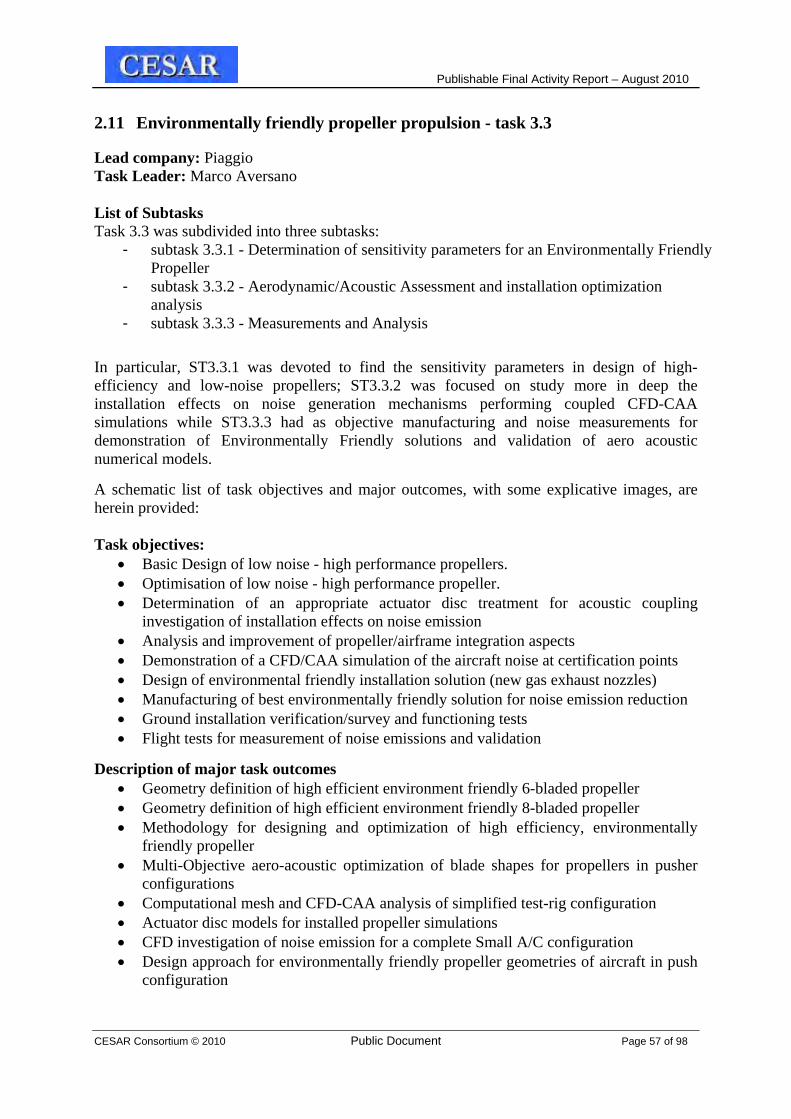
Publishable Final Activity Report – August 2010
CESAR Consortium © 2010 Public Document Page 57 of 98
2.11 Environmentally friendly propeller propulsion - task 3.3
Lead company: Piaggio Task Leader: Marco Aversano List of Subtasks Task 3.3 was subdivided into three subtasks:
- subtask 3.3.1 - Determination of sensitivity parameters for an Environmentally Friendly Propeller
- subtask 3.3.2 - Aerodynamic/Acoustic Assessment and installation optimization analysis
- subtask 3.3.3 - Measurements and Analysis
In particular, ST3.3.1 was devoted to find the sensitivity parameters in design of high-efficiency and low-noise propellers; ST3.3.2 was focused on study more in deep the installation effects on noise generation mechanisms performing coupled CFD-CAA simulations while ST3.3.3 had as objective manufacturing and noise measurements for demonstration of Environmentally Friendly solutions and validation of aero acoustic numerical models.
A schematic list of task objectives and major outcomes, with some explicative images, are herein provided: Task objectives:
Basic Design of low noise - high performance propellers. Optimisation of low noise - high performance propeller. Determination of an appropriate actuator disc treatment for acoustic coupling
investigation of installation effects on noise emission Analysis and improvement of propeller/airframe integration aspects Demonstration of a CFD/CAA simulation of the aircraft noise at certification points Design of environmental friendly installation solution (new gas exhaust nozzles) Manufacturing of best environmentally friendly solution for noise emission reduction Ground installation verification/survey and functioning tests Flight tests for measurement of noise emissions and validation
Description of major task outcomes Geometry definition of high efficient environment friendly 6-bladed propeller Geometry definition of high efficient environment friendly 8-bladed propeller Methodology for designing and optimization of high efficiency, environmentally
friendly propeller Multi-Objective aero-acoustic optimization of blade shapes for propellers in pusher
configurations Computational mesh and CFD-CAA analysis of simplified test-rig configuration Actuator disc models for installed propeller simulations CFD investigation of noise emission for a complete Small A/C configuration Design approach for environmentally friendly propeller geometries of aircraft in push
configuration

Publishable Final Activity Report – August 2010
CESAR Consortium © 2010 Public Document Page 58 of 98
Design approach for gas exhaust geometries minimizing installation effects on noise
emissions of aircraft in push configuration Noise mapping of installed propeller – Ground and Flight measurements on P.180
reference configuration
Figure 61: Definition of two basic low noise – high efficiency propeller geometries and aero acoustic multi-objective optimization of blade plan form through multi-disciplinary analyses

Publishable Final Activity Report – August 2010
CESAR Consortium © 2010 Public Document Page 59 of 98
Figure 62: uRANS CFD models for simulating the unsteady flow around both simplified and complete airframe of the Piaggio P180 Avanti II (Virtual Test Rigs
)
Figure 63: Actuator disc models for installed propeller simplified CFD simulations
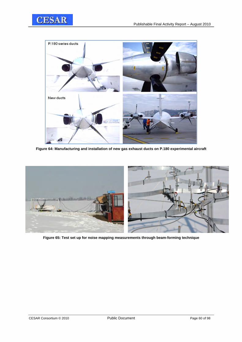
Publishable Final Activity Report – August 2010
CESAR Consortium © 2010 Public Document Page 60 of 98
Figure 64: Manufacturing and installation of new gas exhaust ducts on P.180 experimental aircraft
Figure 65: Test set up for noise mapping measurements through beam-forming technique

Publishable Final Activity Report – August 2010
CESAR Consortium © 2010 Public Document Page 61 of 98
2.12 Cost effective actuation – task 4.1
Lead company: University of Manchester Task Leader: Nigel Schofield List of Subtasks: Subtask 4.1.1 - Efficient and low weight electro-hydraulic actuation Subtask 4.1.2 - Advanced concept of electro-mechanical actuation Task objectives: Develop concepts of new, low weight and low cost electro-hydraulic actuator (EHA) and electro-mechanical actuator (EMA) with the use of new materials, design concepts and motor/power electronic technologies – EMA and EHA “systems”. Specific objectives are to:
Reduce both the cost and the weight of small aircraft flight actuation by the use of material technologies, topologies and the development of more electrical techniques.
Develop actuator-motor-drive systems that will meet the requirements for electrical actuation on small aircraft.
Investigate and define typical small aircraft actuation specification requirements and candidate architectures.
Develop design methodologies to shorten the design to product route, thus reducing future system development costs while improving the informed decision making design process.
Brushless permanent magnet machine and power electronic conversion design concepts are researched against the actuation specification requirements to appraise suitable solutions in terms of cost, mass and system efficiency. A high level of component integration will be sought to minimise cost and mass in future systems.
Subtask 4.1.1 - Efficient and low weight electro-hydraulic actuation
Lead company: University of Manchester Subtask Leader: Nigel Schofield Subtask objectives: The objectives of this sub-task are to investigate: EHA and EMA topologies VSI and CSI power converter topologies for EHA and EMA systems Electromagnetic machine and power converter designs for multi-phase systems. A number of EHA and EMA topologies have been studies and Czech patents filed to cover 3 innovations evolving from this task. Prototype actuation systems have been designed, built and test evaluated at the University of Manchester and Jihlavan. Figure 66.1 illustrates the general assembly drawings of the test facility (a) and test facility hardware at UOM (b). The test facility comprises of two brushless permanent magnet machines and an integrated mechanical assembly that forms the major element of the patent claim.

Publishable Final Activity Report – August 2010
CESAR Consortium © 2010 Public Document Page 62 of 98
(a) Two motor EMA test validation platform. (b) EMA test facility at UOM
Figure 66.1 Two machine actuation test evaluation facility. Comparison of actuation drive systems Voltage (VSI) and Current Source Inverter (CSI) converter structures have been
researched and analyzed. Hardware has been designed and assembled to test validate the converter structures and allow the experimental comparison of each topology. The CSI shows a significant reduction is electrolytic capacitor requirement and reduction in switching device VA when considering field-weakening operation of the drive system.
Brushless permanent magnet (BLPM) machine models have been developed in Matlab/Simulink to numerically evaluate multi-phase designs, specifically a trade study between 3- and 9-phase topologies. A representative 1kW BLPM machine was designed suitable for 3- and 9-phase configuration such that comparisons could be evaluated between the two topologies. The trade studies and tests show an improvement of between 15-25% torque density depending on the deployed control strategy.
Subtask 4.1.2 - Advanced concept of electro-mechanical actuation Lead company: University of Manchester Subtask Leader: Nigel Schofield Subtask objectives: Objective of this effort is to investigate and develop advanced concept of Fluid Metering Pump (FMP) which shall meter the fuel for a small turbine engine just by varying it’s RPM. This concept should bring more simple and cost effective solutions for fuel control of small turbine engines. Fluid Metering Pump (FMP) A FMP system has been designed and evaluated as an example electrical actuation system. The Fluid Metering Pump (FMP) is composed of four main components: a 28 Vdc brushless DC motor (BLDCM), a brushless DC motor electronic controller (FMPC), a fuel pump driven directly by the motor, a STOP valve

Publishable Final Activity Report – August 2010
CESAR Consortium © 2010 Public Document Page 63 of 98
The FMP shall be able to control the fuel flow by varying of pump speed. The attention shall be focused to the influence of ambient conditions and to pump performance stability. Figure 66.2 illustrates the FMP concept (a) and the FMP test equipment (b).
(a) FMP concept (b) FMP test equipment
Figure 66.2 FMP concept and test equipment Conclusions: Studies and development works that have been performed within the CESAR project have had as their task several objectives that should serve for evaluation of new design approaches and assessment of readiness of new technologies and their usability for development of aerospace applications. The Task delivered the following contribution to general project objectives: Modular design (control, power, sensors) Reduction of development time (15%) Reduction of development costs (20%) Increased reliability and safety (difficult to quantify) Increased performance (30%)

Publishable Final Activity Report – August 2010
CESAR Consortium © 2010 Public Document Page 64 of 98
2.13 Competitive technologies for air systems - task 4.2
Lead company: Liebherr-Aerospace Toulouse Task Leader: Nathalie Duquesne / Magali Forget
List of Subtasks Task 4.2 was subdivided into two subtasks:
- subtask 4.2.1 - Environmental Control Systems (ECS) - subtask 4.2.2 - Cabin Pressure Control Systems (CPCS)
Task objectives The main tasks carried out by aircraft air systems are to bleed air from the engines, to cool this air to the suitable temperature then to distribute this air to the various cabin zones at the right temperature, finally to control the air pressure for the passenger's comfort and aircraft safety. CESAR task 4.2 should reach these objectives for small aircraft with specific and strong requirements on costs reduction. The objectives of this task are then to design adapted air systems for both air conditioning and pressurization by taking into account airframers requirements in terms of functional requirements, interfaces, operating requirements and certification aspects.
Subtask 4.2.1 Environmental Control Systems (ECS) The main objective of this subtask was to develop an integrated Environmental Control System (air conditioning system) adapted in terms of functions and costs to small aircraft.
Partners involved in this task were: LIEBHERR TOULOUSE SAS (LTS), TECHNOFAN (TF), SRM, EADC-IW, DAHER-SOCATA, PIAGGIO AERO INDUSTRIES and PBS.
Two systems were simultaneously and independently developed : - an air cycle solution proposed by PBS upon AERO VODOCHODY specifications
(developed aside Task 4.2) - a vapour cycle solution proposed by LTS upon DAHER-SOCATA and PIAGGIO AERO
INDUSTRIES functional specification.
The developed vapour cycle system resulted from a system trade-off conducted to select the most appropriate architecture answering air framers requirements. From there, LTS issued sub-systems and components technical specifications. Cost reductions targets as well as other system targets such as weight reduction and maintenance improvements were also set. Based on these requirements, the task partners performed trade-off at components level and proposed the most appropriate solution for CESAR aircraft: - for LTS : lighter, cheaper and with reduced maintenance Main Heat Exchanger ; low cost
thermostatic valves ensuring regulation aspect and better performances ; low cost evaporator and condensers based on automotive components
- for TECHNOFAN : low cost fans with speed regulation - for SRM : a oil-free screw compressor - EADS-CRC : evaluation of regenerative air purification systems
These technological innovations (except for air purification systems) were developed and tested against the system requirements. A representative test rig integrating all developer

Publishable Final Activity Report – August 2010
CESAR Consortium © 2010 Public Document Page 65 of 98
components has finally been built up and successfully validated in terms of systém performance with regards the air framers requirements.
Below are presented some of the major components and the test bench developed within subtask 4.2.1:
Figure 66: Some of the major components and the test bench developed within ST 4.2.1
Subtask 4.2.2 Cabin Pressure Control Systems (CPCS) The main objective of this subtask was to develop a cabin pressure control system adapter in terms of comfort, safety and costs to small aircraft.
As for the ECS, LTS analyzed DAHER-SOCATA and PIAGGIO AERO INDUSTRIES functional specification and performed a system trade-off in order to select the most appropriate architecture answering air framers requirements. LTS issued components technical specifications and developed them upon cost reductions targets as well as other system targets such as weight reduction and maintenance improvements.
LTS mainly focused on: developing of low cost electro-pneumatic valve for reduced crew work load;
integrating components from automotive/industrial applications (material).
Two valves were developed, a Pressure Regulating Valve (PRV) and an Electropneumatic Outflow Valve (EOV)), and were tested onto a dedicated test bench. Results at components level showed compliancy with objectives and requirements to be reached, validating therefore the system performance with respect the air framers requirements.

Publishable Final Activity Report – August 2010
CESAR Consortium © 2010 Public Document Page 66 of 98
Figure 67

Publishable Final Activity Report – August 2010
CESAR Consortium © 2010 Public Document Page 67 of 98
2.14 Integrated diagnostics and on condition maintenance - task 4.3
Lead company: Eurocopter Task leader: Dr-Ing Samir GHELAM List of Subtasks Task 4.3 was subdivided into two subtasks:
- subtask 4.3.1 - Optimized high sensitivity diagnostic - subtask 4.3.2 - Integrated diagnostic and on-condition maintenance systems
Health monitoring and management The task 4.3 has provided specifications and guidelines and demonstrators (TRL6) for the design of future maintenance concepts. The research has allowed to reach TRL 6 for health management technologies applied to: - Avionics - Hydraulics - Engines
Both on board and ground aspects are covered by the study. The off board system also needs to be able to display system operating conditions. Design guidelines have also been described for ground segment, which allow use of COTS for further deployment.
An architecture mixing different technologies depending on the requirement and the component allows interfacing system components without forcing the use of a single technique.
A fully integrated maintenance system using the interfaces of the OSA-CBM architecture, allows for further OSA-CBM computations, and uses this information to generate maintenance actions. Integrated diagnostics and on condition maintenance system The WP has initiated the design of a Data Concentrator (DCU) for data fusing from the various airborne systems and the Quick Access Recorder (QAR) for data recording that will form the backbone of the IDAOCMS for a CESAR type aircraft.
We have proposed suitable communication interfaces that could be implemented in this architecture, which is based on an Ethernet network. These interfaces consist of the input communication interface on the one hand and the output communication interface on the other hand. The DCU unit we have designed implements these protocols such that the selected airborne systems (Engine, Hydraulics, and System Health Assessment) are expected to be linked to the DCU and communicate with it using the proposed input protocol. A demonstration platform has been devised by our partner NLR, on which we worked together in the final phase of the CESAR project. This resulted in a Lab evaluation session that has been conducted by SPEEL and NLR at SPEEL facility

Publishable Final Activity Report – August 2010
CESAR Consortium © 2010 Public Document Page 68 of 98
The Test bench consisted of a Flight Simulator that is used as an aircraft systems data source and the airborne portion of IDOCMS comprising the DCU and the QAR units developed by SPEEL.
Advanced detection methods evaluation for engine parts The work involved the development of methods and practices for in situ tribological monitoring of aircraft engine components. This included research on vibrations as well as on lubrication monitoring systems, including:
- Review possible anti-friction coatings - Provide wear debris particulates for analytical techniques - Develop best practice for surface sampling and evaluate the diagnostic check
list - Evaluate the feasibility of developing new portable friction probe - Optimisation of methods defining the source and level of vibrations, - Development of algorithms analysing the vibration of the powerplant - Data fusion techniques
Figure 68: Test-bed airplane is shown in the foreground
Figure 69

Publishable Final Activity Report – August 2010
CESAR Consortium © 2010 Public Document Page 69 of 98
Pitting Scuffing
Hydraulics The purpose of the work was to state diagnostics possibilities and diagnostics potential gains in the aircraft hydraulic system and in the rudder control system.
Basic solution gains take effect in: Maintenance achieving in accordance to stage (must be planed to don´t realize
maintenance of single devices scores of the time) Achieving of higher device reliability Optimization of the solution
Avionics Equipment of aircrafts will be automatically tested by BIT. The interpretations of these messages will allow the maintenance operator to have knowledge of what should be replaced in order to restore the aircraft. But in addition some new features have been developed in the framework of CESAR linked to the treatment of many failures arising from BIIT that will now be treated automatically, in order to decrease
False warnings Failure localisation
These two problems solved by new algorithms before providing to the maintenance operator the maintenance operation to be performed. Benefits brought by WP4.3 research
• Reduction of development cost • Reduction of manufacture costs • Reduction of operational costs:
- Prevention
- Reduction of the maintenance
- Increase in engine life.
• Increase in flight safety • Increase in operation efficiency
Figure 70: Friction Curves of gears and bearings materials observed during tests

Publishable Final Activity Report – August 2010
CESAR Consortium © 2010 Public Document Page 70 of 98
2.15 New Design and Development Concept - task 5.1
Lead company: NLR Task leader: Toni Kanakis List of subtasks Task 5.1 was subdivided into two subtasks:
- subtask 5.1.1 – Integrated design system - subtask 5.1.2 – Processes management, knowledge management
Partners: NLR, INCAS, TM, Piaggio, Evektor, AERNNOVA, CENAERO Task Objectives Develop innovative tools and techniques for integration of engineering disciplines, methods, tools, databases to support novel optimization strategies and multi-partner collaborative design of small aircraft. CESAR - Integrated Design System:
• Integration of various disciplines involved during the pre-design phase into an Integrated Design System (IDS) able to provide a collaborative media for distributed partners;
• Contribution to the development and production usage of a multidisciplinary design and optimisation (MDO) environment for small commercial aircraft;
• Develop the appropriate tools to support information, and data sharing between individual dedicated tools (i.e. aerodynamics, structures, engines, systems optimization) towards subsequent design phases;
CESAR - Process and Knowledge Management: • Investigations and development of the process to transfer information learnt in
support activity to design area; • Develop the appropriate tools and environment to allow dissemination of knowledge
and resources among the European enterprises and research centres; Results in task 5.1:
• Functional analysis of design process for small aircraft, yielding towards an integrated approach for conceptual design, pre-design, design, development and production
• Product-data management throughout the life cycle of small aircraft, including maintenance
• Multi-disciplinary design and optimisation (MDO) environment • Integrated optimising fatigue analysis tool • Improved collaboration in subsequent design phases, through secure remote
information sharing and coordination of multi-partner engineer jobs • Automated tool chain for conversion from CAD to CFD • In service data management
Proof-of-concepts are demonstrated in the context of the CESAR use cases.

Publishable Final Activity Report – August 2010
CESAR Consortium © 2010 Public Document Page 71 of 98
Figure 71: IDS and CESAR project framework
.
Figure 72: IDS -MDO framework for a/c pre-design
Figure 73: CESAR Conductor Workflow System (CWS) - Improved collaboration in subsequent design phases, through secure remote information sharing and coordination of multi-partner engineer jobs

Publishable Final Activity Report – August 2010
CESAR Consortium © 2010 Public Document Page 72 of 98
Figure 74: Conversion tool for CFD analysis and optimization, and CESAR fatigue tool
Figure 75: ISDM tool
Figure 76: EVEKTOR Maintenance System (EMS)

Publishable Final Activity Report – August 2010
CESAR Consortium © 2010 Public Document Page 73 of 98
2.16 Evaluation Platforms - task 5.2
Lead company: Piaggio Aero Industries S.p.A. Task Leader: Mauro Minervino List of subtasks Task 5.2 was subdivided into two subtasks:
- subtask 5.2.1 – Definition and baseline configuration - subtask 5.2.2 – Trade off studies and assessment
Task Overview Task 5.2 activities started at the very beginning of CESAR program with the definition of Top Level Aircraft Requirements for the reference platforms (standard technology aircrafts to perform evaluation of CESAR technologies at aircraft level, following referred to as AC1/2), basically in terms of: seating capacity, cabin/baggage compartment dimensions, reference flight profile and relative mission/point performance requirements, operating envelope limitations, cabin pressurization requirements (AC2 only) and structural requirements concerning operational life and fatigue damage inspection.
These specs were suddenly followed by the definition of AC1/2-ref architecture, technology, equipments and avionics, leading to the issue of design reporting in the form of technical description documents, three-view drawing of selected configurations, cabin cross section and cabin layout sketches.
This allowed to perform a preliminary sizing and flight performance analysis complying both certification basis and TLARs. Preliminary estimations of basic operational weight and aerodynamic performance, together with the selection of suitable AC1/2-ref propulsion systems were the basis to size both aircrafts and define flight envelopes and PayLoad vs Range charts.
This first stage of Task work ended with the build-up of Digital MockUps for both AC1-ref and AC2-ref on the basis of the defined shape and architecture. Subsequently, most of other CESAR tasks started to developed applications of new assessed technologies to be embedded on AC1/2, thus providing valid candidates to replace standard technologies of baseline aircrafts.
Once this developing phase was completed by all partners, work was back on Task 5.2 to make a synthesis, selection and final assessment of CESAR technologies, providing the basis for all trade-off studies between standard vs CESAR design aircrafts.
Overall benefits evaluation in terms of aircraft weight, selling price, performance and manufacturing/operating costs was performed after a second loop of AC1/2 sizing and performance analysis, that led to the definition of new aircraft 1st level OEW and costs brake-down taking advantages of weight/cost savings allowed by new CESAR selected technologies, new AC1/2 design weights and mission performance.

Publishable Final Activity Report – August 2010
CESAR Consortium © 2010 Public Document Page 74 of 98
Achieved results and their contributions to the general measurable project objectives: ▫ Improvements in terms of flight performance and selling price. Below chart shows results
for AC2 :
Figure 77: Results for AC2
▫ Improvements in terms of direct operational costs. DOCs have been evaluated for AC1
and AC2 on reference 200 nm and 300 nm missions respectively:

Publishable Final Activity Report – August 2010
CESAR Consortium © 2010 Public Document Page 75 of 98
Figure 78
Figure 79
Table below shows the comparison between CESAR target and achieved cost reduction:
Aircraft Category Average
Manufacturing Costs
CESAR Objectives
Achieved Reduction
Unpressurized Turboprops € 900,000 -16% - 10%
Small jets € 3,000,000 -17% -8.64%

Publishable Final Activity Report – August 2010
CESAR Consortium © 2010 Public Document Page 76 of 98
3. PLAN FOR USING AND DISSEMINATING THE KNOWLEDGE
The plan for using and disseminating the knowledge the contractors will set out in a detailed and verifiable manner, the terms of use and dissemination of the knowledge arising from the project, which they own, in accordance with their interests (Article II.34.1 of the contract). 3.1 Exploitable knowledge and its use
This section will only present exploitable results, defined as knowledge having a potential for industrial or commercial application in research activities or for developing, creating or marketing a product or process or for creating or providing a service.
It should provide an overview, per exploitable result, of how the knowledge could be exploited or used in further research (if relevant). This should be created by the project coordinator obtaining input from each contractor that owns the knowledge and has an active role in its exploitation. Both past and planned future activities should be included.
Exploitation and dissemination activities are part of T0.3 and T0.4 and are closely linked with the work of PAB (the Project Advisory Board) and Exploitation Manager. The large number of individual deliverables does not give an opportunity to describe in detail each result and its exploitation. After some discussion, the combined approach in a form of the tables was selected for recording of project results covering exploitation, protection, publication and dissemination aspects.
The results are recorded in the single file entitled as „Plan for exploitation, protection, publication and other dissemination of project results“. The main aim is to provide the Consortium with the detail view on the project results and their potential use and dissemination. The plan was issued as a comprehensive deliverable report D0.3-2/D0.4-3 and the final version D0.3-3, which is also the Annex of this Activity Report.
A special methodology was developed and applied for this purpose. Every record contains the identification of the particular result of the certain task. The record includes the type of the result and result description, the type of use and date of the first exploitation, type of IPR protection, further publishing plans, determination of owners of the results and contribution of the particular result to the general CESAR project objectives.
The listing of project results shows transparently real expectations of participants from the CESAR project. The document also helps the project partners to identify and solve any problems with the IPR ownership. Plans for use, publication and dissemination are part of this document as well.
Conclusion: The document „Plan for exploitation, protection, publication and other dissemination of project results“ have been finalized having 33 pages listing major outcomes of CESAR project.

Publishable Final Activity Report – August 2010
CESAR Consortium © 2010 Public Document Page 77 of 98
3.2 Dissemination of Knowledge
The dissemination activities section should include past and future activities and will normally be in the form of a table maintained by the coordinator or any other person charged with controlling the dissemination activities.
The detail dissemination plan for the concrete project results is part of „Plan for exploitation, protection, publication and other dissemination of project results“ see the chapter 4.1 above. General events and actions for public awareness and supporting dissemination of knowledge generated by CESAR project are listed in the table below.
General events and actions for public awareness and dissemination of knowledge
Planned /actual Dates
Type Type of audience
Countries addressed
Size of
audience
Partner responsible/
involved
FIRST PROJECT YEAR
3/06 Press release - Czech Aviation Initiated International Research Project
general public Czech - VZLU
5/06 EREA Newsletter - CESAR integrated project - general information
general public EU EREA
4/07 EPATS Workshop expert public EU 20 VZLU
5/07 The Member States Workshop - Integrating European Research Capability in Aeronautics
EU
6/07 Project website - launch general public global VZLU
6/07 EWA/UFAST Joint Workshop expert public global ~35 IoA
7/07 Press release- Project Abstract (article on web) expert public global VZLU
SECOND PROJECT YEAR
9/07 EWA Joint Workshop expert public global ~50 IoA
9/07 The Prague Post - article of ALV, CESAR mentioned general public global - ALV
12/07 KATnet II workshop - presentation of CESAR outputs
expert public EU - VZLU
4/08 CESAR project mentioned in article in Ekonom journal (CZ) - March
general public Czech - VZLU
4/08 CESAR a challenge for general aviation in Europe - leaflet placed on the web - includes project outputs
general public global VZLU
4/08 Aerospace Testing in Munich - CESAR project mentioned in Editorial Show Catalogue
expert public global UNIS
5/08 CESAR project presentation at ILA Berlin Airshow, stand of EREA
expert public global - VZLU

Publishable Final Activity Report – August 2010
CESAR Consortium © 2010 Public Document Page 78 of 98
Planned /actual Dates
Type Type of audience
Countries addressed
Size of
audience
Partner responsible/
involved
9/08 Information about safety related tasks was sent to EASA to Mr. Audard Clement for EGATS (European General Aviation Safety Team)
expert authority
EU - VZLU
THIRD PROJECT YEAR
11/09 International conference for Defectoscopy and Health Monitoring in Brno
expert public global hundreds
VZLU
6 Feb 09
AirTN Thematic Forum 3 held on 6 Feb 2009 – CESAR project contribution to General Aviation industry in EU
expert public 80
18-19 March 09
1st Training Workshop - Aerodynamic design tools, workshop program is ready
expert public, participants
EU Consortium
+ users
5/09 Katnet II Conference on Key Aerodynamic Technologies- 12-14 May 2009, Bremen, Germany
expert EU -
19 May 2009
CEARES in Žilina expert public EU 60 Consortium
partners on 7-8 July 2009
"General Aviation and European Air Transport System” Warsaw
expert public EU 100
First project year EWA/UFAST Joint Workshop – took place in VZLU in Praha on 5-6 June 2007. The main objective was validation of numerical methods by experiments in aerodynamics. Dr Wojciech Kania from IoA represented Institute of Aviation. His presentation showed Wind tunnel testing in numerical aerodynamic design process in Institute of Aviation. In the presentation the main goals for current and planned research works of IoA within the WP1 - Aerodynamic Design of CESAR project has been pointed out. The works involved numerical aerodynamic design of airfoils and wings for low and high speed small aircraft. The numerical results will be experimentally validated in IoA's wind tunnels.
EPATS (European Personal Air Transportation System) Expert Workshop took place in the EUROCONTROL Experimental Centre in Bretigny sur Orge (France) on 19 April 2007. More than 20 participants from 11 countries attended the workshop and 10 presentations were listened and discussed. Mr. Josef Jironc from VZLU presented general objectives of CESAR project. He highlighted interrelations with the EPATS intentions and expressed interests of joint meeting between CESAR and EPATS especially at the moment of workpackage concerning CESAR components integration.
The Member States Workshop - Integrating European Research Capability in Aeronautics - took place in the Centre Albert Borschette in Brussels on 22 May 2007. The main objective was to assess and learn different experiences with EU Framework Programmes, in particular in the new Member States. Mrs. Pavlina Makovska from VZLU represented ALV CR (Czech Association of Aviation Manufacturers). Her presentation showed quite wide experience of the Czech Republic with participation in the Framework Programmes aimed at aeronautics.

Publishable Final Activity Report – August 2010
CESAR Consortium © 2010 Public Document Page 79 of 98
She pointed out integrated project CESAR (Cost Effective Small AircRaft) which supports competitiveness of European manufacturers of aircraft between 5-15 passengers. The development potential of General Aviation in EU and possible support for this sector have been discussed with representatives of the European Commission. Several new member states declared that they will extend their R&D and manufacture activities in General Aviation in the near future.
Project website has been launched in June 2007 on www.cesar-project.eu
Second project year
EWA Joint Workshop – took place in DLR in Göttingen on 17-18 September 2007. The main objective was exploring the needs of the wider community of wind tunnel users. Dr Jerzy Żółtak from IoA represented Institute of Aviation. His presentation showed Aerodynamic Activities at Institute of Aviation. In the presentation the main goals for current and planned research works of IoA within the WP1 - Aerodynamic Design of CESAR project has been pointed out. The works involved numerical aerodynamic design of airfoils and wings for low and high speed small aircraft. The numerical results will be experimentally validated in IoA's wind tunnels.
Katnet II workshop - The CESAR project overview was presented at KATnet II Multi Disciplinary Design & Configuration Optimisation Workshop held 28 – 29 January 2008 at DLR in Braunschweig, Germany. KATnet II is a Thematic Network on Key Aerodynamic Technologies for Aircraft Performance Improvement, funded by EC. The presentation emphasises the focus of the project on the general aviation categories of aircraft, on the integral and multidisciplinary aspects of the project covering several fundamental areas of the aircraft design and operations, on the multinational and multi-partner character of the project.
ILA Berlin Airshow - Cesar project was represented also at ILA airshow held at the end of May 2008 in Berlin. CESAR´s information leaflets were part of the EREA stand so at least kind of basic awareness about the project was ensured.
Third project period
CESAR project was presented at several events:
International Conference for Defectoscopy in Brno
AirTN Thematic Forum for General Aviation held at CIRA in Capua
Training workshop for Aerodynamics
Katnet II Conference for Key Aerodynamic Technologies held in Bremen
CEARES project workshop held in Zilina in Slovakia
Polish workshop for General Aviation held in Warsaw.

Publishable Final Activity Report – August 2010
CESAR Consortium © 2010 Public Document Page 80 of 98
3.3 Publication
The technical publications were essential part of dissemination activities of CESAR project. Participants were encouraged to publish technical achievements, provided that IPR protection was solved, using the procedure described in the Handbook (a 30 day tacit approval requested from the whole consortium and EC). Finally there were 48 official publication approved. A special copy of the Czech Aerospace Proceedings was dedicated to CESAR project. The good point is that the journal has ISSN number it means it is internationally recognized. The journal was published in November 2009 containing about 14 technical articles in English language. The journal was distributed in a paper version as well as in pdf format http://www.vzlu.cz/download.php?file=356

Publishable Final Activity Report – August 2010
CESAR Consortium © 2010 Public Document Page 81 of 98
List of publications No, Author(s) Company Title Conference/Event When/where
1 Ing. Martin Sveda
UNIS MATHEMATICAL MODEL OF A SENSORLESS BLDC MOTOR FOR AEROSPACE ACTUATORS
IASTED conference in Canada 26‐28 May 2008
2 Peter Eliasson FOI
EFFECT OF EDGE‐BASED DISCRETIZATION SCHEMES IN COMPUTATIONS OF THE DLR F6 WING‐BODY CONFIGURATION
AIAA Fluid dynamics conference in Seattle
June 23‐26
3 Olivier Amoignon
FOI AESOP ‐ A Program for Aerodynamic Shape Optimization
4
Jiri Hlinka
VUT Brno Experience with Failure Rate Estimates and Component Importance Measures for General Aviation Aircraft Systems
conference "Reliability, safety and diagnostics of transport structures and means 2008" (Pardubice, Czech republic) in September 25‐26.
5 Antonio Pagano
CIRA Multiobjective Aeroacoustic Optimization of an Aircraft Propeller (Pagano, Federico, Barbarino, Guida, Aversano)
AIAA‐2008‐6059, 12th AIAA/ISSMO conference, Victoria, BC,
10‐12 Sep. 2008
6
Běhal, Makarov
VZLU Detection of Disbonding of Composite Patch Airframe Repair by Acoustic Emission and Ultrasound
38th International Conference Defektoskopie, 4.‐, Brno, Czech Republic
6 Nov 2008
7 Běhal
VZLU Health Monitoring of Composite Aircraft Structure in the Course of Static Strength Testing
38th International Conference Defektoskopie, Brno, Czech Republic
6 Nov 2008
8
Seitz
DLR
Design of Laminar Transonic Airfoils
Notes on Numerical Fluid Mechanics and Multidisciplinary Design (NNFM, Springer‐Verlag
11 Dec 2008
9 Klomp‐de Boer, R. [[email protected]]
NLRDevelopment of a Cost Efficient Composite Wingbox for Small Aircraft
the 3rd International IIR Conference "Composite and Lightweight Structures in Aircraft"
6‐7 May 2009 Hamburg ‐ Germany
10
Mr. Nigel Schofield
UoM Current Source Inverters for PM Machine Control
11 Mr. Nigel Schofield
UoM Direct Torque Control of Permanent Magnet Motors Using a Single Current Sensor
12 Mr. Arne Stuermer
DLR Coupled uRANS and FW‐H Analysis of Installed Pusher Propeller Aircraft Configurations
AIAA/CEAS Conference 11‐13 May 2009
13 Mr. Martin Sveda
UNIS Development of COTS based engine control system and intelligent actuators for small aircraft
Aerospace Testing 21‐23 April 2009
14 Mr. V. Hubík
UNISTest bench for electrical drives
Measurement 09, Smolenice, Slovakia
20‐23 May 2009
15 Mr. V. Hubík Mr. Martin Sveda Mr. Vladislav Singule
UNISVUT Brnos SENSOR BLDC MOTOR MODEL IN SIMULINK
ENVIRONMENT IASTED 09 conference in Canada, Not presented
Not presented
16 Mr. Jan Kraus
Jihlavan Half‐hot stand‐by system as a step to realize on‐condition maintenance
?
17 Mr. Martin Sveda and co‐authors
UNISModern Methods of FADEC Design for Aircraft Engines and Certification Aspects
14th International Congress of Propulsion Engineering,
September 14‐19, 2009, Rybachye, Ukrajine,

Publishable Final Activity Report – August 2010
CESAR Consortium © 2010 Public Document Page 82 of 98
No, Author(s) Company Title Conference/Event When/where
18 Mr. Martin Sveda and co‐authors
UNISPOWER PLANT CONTROL & MONITORING SYSTEMS FOR SMALL UTILITY AIRCRAFT AND MODERN TRENDS IN ACTUATION
14th International Congress of Propulsion Engineering,
September 14‐19, 2009, Rybachye, Ukrajine,
19 Dr. Michael Scheerer
ARCSComparison of different sensor technologies for Ae based impact damage detection
7th Int. Workshop on Structural Health Monitoring
, Stanford University, Stanford, US 09 ‐ 11. Sept 2009
20
Ing. Jiří Čečrdle, Ph.D.
VZLU Optimization Solution for Determination of Whirl Flutter Stability Boundaries
Czech Aerospace Proceedings November 2009
21 M. Švéda, V. Hubík, I. Szabó
UNIS Development of Control System for Fuel Metering Pump
Int. Conference IECON 2009, Porto, Portugal
3‐5 November 2009
22 M. Švéda, V. Hubík, V. Opluštil, P. Axman, T. Kerlin
UNISModel based development of COTS Complex Power‐plant Control System
Int. Conference IECON 2009, Porto, Portugal
3‐5 November 2009
23 Marian Zabloudil
VZLU AERODYNAMIC OPTIMIZATION OF AIRFOIL AND WING WITHIN THE CESAR PROJECT IN VZLU
CEAS 2009, Manchaster 26.‐29 Oct 2009
24 V. Hubik, T. Kerlin, J. Toman
UNISModel Based Design for EC motor control
Conference Engineering Mechanics 2009, Svratka, Czech Rep.
11‐14 May 2009
25
E.Pietropaoli, A.Riccio, G.Mozzillo
CIRA ANALYSIS OF THE EFFECTIVENESS OF DIFFERENT FINITE ELEMENT MODELIZATIONS FOR THE SIMULATION OF THE BEHAVIOUR COMPOSITE PLATES IN PRESENCE OF DELAMINATIONS: AN ESSENTIAL STEP TOWARDS A FULLY DAMAGE TOLERANT DESIGN APPROACH
Czech Aerospace Proceedings November 2009
26 E.Pietropaoli, A.Riccio, A.Raimondo3 1
CIRA A FRACTURE MECHANICS BASED ENERGY APPROACH FOR THE DETERMINATION OF THE DAMAGE TOLERANCE OF A COMPOSITE WING BOX: SENSITIVITY ANALYSIS TO THE DELAMINATION DIMENSION AND POSITION.
Czech Aerospace Proceedings November 2009
27 M. Belardo1, M. Pecora2
NONLINEARITIES IN FLUTTER EVALUATION Czech Aerospace Proceedings November 2009
28 Dr. E.H. Baalbergen, Dr.ir. W.J. Vankan, Dipl.‐Ing. A. Kanakis
NLRA practical approach for coordination of multi‐partner engineering jobs in the design of small aircraft
Czech Aerospace Proceedings November 2009
29 Y. Essa, F.M. de la Escalera
Aernnova FATIGUE TOOL EVALUATION OF SMALL AIRFRAME STRUCTURES
Czech Aerospace Proceedings November 2009
30 V. Hubik, M. Sveda, V. Oplustil
UNIS Development of complex electronic control systems using new design approaches based on integrated simulation tools
Czech Aerospace Proceedings November 2009
31 Kraus Jihlavan Solutions to Hydraulic Circuit Diagnostics Czech Aerospace Proceedings November 2009
32
M. Debski
IoA THE IDEA OF CONTINUOUS LOADS AND FATIGUE ESTIMATION OF AIRCRAFT STRUCTURES ‐ AUTONOMOUS LOADS AND FATIGUE RECORDER
Czech Aerospace Proceedings November 2009
33 Mr. Antonio Calabro and Mr. DIMINO IGNAZIO
CIRA STRUCTURAL DAMAGES IDENTIFICATION BY VIBRATION PARAMETERS AND FIBRE OPTIC SENSORS
Czech Aerospace Proceedings November 2009
34 T. Hubáček
PBS MEASUREMENT OF HIGH SPEED GEARBOX DYNAMIC PROPERTIES
Czech Aerospace Proceedings November 2009

Publishable Final Activity Report – August 2010
CESAR Consortium © 2010 Public Document Page 83 of 98
No, Author(s) Company Title Conference/Event When/where
35 Hájek, Zabloudil
VZLÚ WING OPTIMIZATION CONSTRAINED BY BOUNDARY LAYER SEPARATION USING NONLINEAR LIFTING LINE METHOD
Czech Aerospace Proceedings November 2009
36 Brouwer
NLR Analytical method for the computation of the noise from a pusher propeller
16th AIAA/CEAS Aeroacoustics Conference
37 M. Belardo
CIRAPRE‐TEST ANALYSES FOR FLIGHT FLUTTER TEST OF A CS‐23 AIRCRAFT
16th US National Congress on Theoretical and Applied Mechanics
June 2010
38 V. Hubík, M. Švéda, V. Singule
VUT Brno, UNIS
SENSOR BLDC MOTOR MODEL IN SIMULINK ENVIRONMENT
29th IASTED International Conference on Modelling, Identification and Control
February 15 – 17, 2010
39 Valerijan Cokonaj
AERNNOVA
Damage detection on mechanically and thermally loaded FGC panels with new Phased Array Transducers
5th European Workshop on Structural Health Monitoring
in July 2010
40 Klomp‐de Boer
NLR Development of a cost effective composite wingbox for small aircraft
SAMPE conference in Seattle 17‐20th May 2010
41 Arne Seitz, Karl‐Heinz Horstmann
DLRDESIGN STUDIES ON NLF AND HLFC APPLICATIONS AT DLR
27TH INTERNATIONAL CONGRESS OF THE AERONAUTICAL SCIENCES, ICAS 2010
Nice from September 19th to 24th, 2010
42 Alexander O. Pugachev
TUM Gradient‐Based Optimization of a Turboprop Rotor System with Constraints on Stresses and Natural Frequencies
the 6th AIAA Multidisciplinary Design Optimization Specialists Conference
April 2010
43 Alexander O. Pugachev
TUM SENSITIVITY ANALYSIS OF SQUEEZE FILM DAMPERS USING REYNOLDS EQUATION
8th IFToMM International Conference on Rotordynamics
2010
44 Michael Scheerer
ARC Validation of Acoustic Emission on Demand Algorithm for Impact Damage Quantification
the 5th Europ. Workshop on Structural Health Monitoring, Sorento, Italy
29.06.
45 Michael Scheerer
ARC Impact Damage Quantification by Analyses of Acoustic Emission Data
14th ECCM, Budapest, Hungary,
07.06. ‐ 10.06.2010
46
Stefanos Giannis
MERL Development of Fatigue Delamination Onset and Growth Criteria for Damage Tolerant Design of Small Aircraft Composite Structures
14th ECCM, Budapest, Hungary
07 – 10 June 2010.
47 Ondřej Lajza
BUT CFD Prediction of Performance Degradation for Ice Accretion Contaminated Airfoil
Czech Aerospace Proceedings April 2009
48 Robert Popela, Ph.D., Petr Doupník
BUT Response surface method application to transonic business‐jet wing optimization
Czech Aerospace Proceedings April 2009

Publishable Final Activity Report – August 2010
CESAR Consortium © 2010 Public Document Page 84 of 98
3.4 Protection of knowledge – patents
The results from CESAR projects are valuable know-how, especially for industrial participants. That is why they made effort to protect their results by patents, design records, utility models or in case of software by copyright law.
List of patents applied including design records/utility models
No. Company (Author(s))
Type of protection: Patent / design record
(national/EU) PATENT general description Task Status
1. Eurocopter Patent
New failure detection method in sensors
4.3 -
2. Jihlavan & UoM National patent
New, high-speed response and reliable solution of the EMA servo
drive for control rudders 4.1
Approval started on 13.Nov 2009 – 13.Dec
2009
3 Jihlavan & UoM National patent
New motor and gearbox solution of the EMA for control flaps or
trim 4.1
Approval started on 13.Nov 2009 – 13.Dec
2009
4 VZLU
(Pompe) National design record
New propeller blade airfoil - Industrial Design Records
3.3 Approval started on
28.1.2010 – 26 February 2010
5 TF National patent
New electrical motor concept
Hybrid switched reluctance motor 4.2 -
6 LIEBHERR/PAI/SOCATA
National patent Cost effectiveness air system 4.2 -
7 EADS G&PIAGGIO
Patent ? Robot based Friction-Stir-Welding process with minimised heat
impact and distortion by using an innovative welding tool concept
2,2
8 VZLU Utility model - national Universal rubber block element for loading system used for
lightweight airframe structures strength tests
2.3
Publishable Final Activity Report – August 2010
CESAR Consortium © 2010 Public Document Page 85 of 98
4. SUMMARY OF TECHNICAL ACHIEVEMENTS
WP1 - Aerodynamic Design
T1.1 - High fidelity design tools
The task served for the definition of two aircraft reference configurations (twin propeller, unpressurized low speed a/c and pressurised small business jet). The main objective of T1.1 was to provide a package of tailored and improved tools for aerodynamic design including guidelines for their use. A number of dedicated tools for numerical analysis have been tailored and assessed using reference configuration and experimental information related to specific aerodynamic design activities (e.g. CFD tools of airfoil analysis, high-lift analysis, tools for aero-design of laminar and turbulent wing, VLM tool for IDS integration, DRMR for experimental aerodynamics, global 3D optimization, tool for propeller effects, jet engine modelling, CAD, meshing tools etc.).
The task T1.1 contributed significantly to the time to market reduction, i.e. reduction of the overall design time and even the development costs. However, it turned out the accurate quantification of the contribution was not fully feasible. That is why the assessment was done individually, only for each tool or for typical use-cases. The contribution of the T1.1 achievements to the design time reduction can be counted in couple of months. For example in case of evaluation of the aircraft configuration the time reduction is from one month to one week per single aircraft configuration. The more detailed analyses of the aerodynamic tools and their contribution to the project objectives is described in the Task 5.1 and relevant deliverable reports (namely in D5.1.1-4)
The adjusted aerodynamic tools and methodology know-how give designers a potential to reduce significantly the number of iterations (esp. blind ones) and finally save both time and money. The task outcomes bring benefits especially to design teams of aircraft manufacturers as well as to research centres who often supports industry with aerodynamic design solving usually rather complex tasks. T1.2 - Advanced Wing
This complex task contributed in great extent to the aerodynamic design improvements. The final results comprise new methodologies and micro genetic algorithms for airfoil design, methods for parameterization of airfoils and wings, adaptation of CFD solvers for wing optimisation, advanced CFD methodology for evaluations of aircraft performance, design methodology for winglets etc. The task also delivered set of new airfoils from low speed aircraft (turboprop) up to transonic speed (VLBizJ) with laminar boundary layer. Within the task T1.2 the methodologies for wing contamination (e.g. ice accretion) and manufacture imperfection were elaborated. The validation phases of all subtasks comprised complex experiments in several wind tunnels (CIRA, INCAS, VZLU, IoA).
The task T1.2 brought new codes and methodologies for aerodynamic designs. The tangible technical knowledge was created especially for wing design area. With respect to general CESAR objectives the optimized wings with lower drag contributed to the increase of fuel

Publishable Final Activity Report – August 2010
CESAR Consortium © 2010 Public Document Page 86 of 98
efficiency, flying range and a higher speed. In case of turboprop aircraft AC1, the laminar wing assessment showed even 10% drag reduction with possibility of speed increase by 8 kt and flying range extended by 119 nm (for turbulent wing by 200 nm). The operation costs decreased from 949 USD to 913 USD (4% costs reduction). The same saving rate is for fuel consumption where 4% reduction was calculated for laminar wing (only 1% for turbulent wing) of AC1 and 3% fuel saving for jet aircraft AC2. The detailed assessment can be found in Task 1.2 and T5.2 chapter and in the relevant deliverable reports (namely in D5.2.2.1-1, D5.2.2.1-2, D5.2.2.2-1 and D5.2.2.2-2). T1.3 - Flight Dynamics
The key objective of the task T1.3 was to evaluate and integrate various methods and tools for rapid assessment of the flight dynamics of different prototypes. A group of software codes and tools were developed such as design software tool for aircraft flight dynamics evaluation, optimisation tool for control system and control surface design, tool for validation of flight data. The methodology for low-cost flight tests of aircraft subscale were developed and proved by in-flight measurements. The flying subscale model for flight dynamic assessments is a valuable tool during the design process, enabling low-cost validation of results from CFD simulations and from windtunnel experiments. Also some specialties like a methodology for validation of near ground effect belong to the task achievements.
The simplified methods for flight dynamics make this kind of tools more accessible to developers and designers of small aircraft. The designers can save development time, counting in several person months. The new method improves quality of design process and reduces the uncertainties of the design process and the flight test required in the certification process. The contribution to development costs reduction can be significant. The more detail analyses of the aerodynamic tools and their contribution to the project objectives is described in the Task 5.1 and relevant deliverable reports (namely in D5.1.1-4) WP2 - Structural Design T2.1 – Operational Loads
The complex software package for operational loads calculations was developed in T2.1. The individual tools cover various load computation areas like CS 23 internal loads distribution on aircraft parts, dynamic loads occurring during landing impact, aerodynamic load distribution on aircraft using DLM, fatigue safe-life calculation and preparation of load for fatigue tests.
Experts in this area believe that the new tools developed in T2.1 can reduce the design time by 4 month, i.e. from 5-6 months which is a common practice to 2 months. The tools can streamline significantly the design process and shorten the development time and save some costs. After some tailoring and user friendly interface development this complex tool for operational load calculation may have ambitions to become standard commercial software used by designers in General Aviation sector.

Publishable Final Activity Report – August 2010
CESAR Consortium © 2010 Public Document Page 87 of 98
T2.2 – New Design Approach to Advanced Airframe Structures
The task work focused on investigation of advanced airframe structures for small aircraft and their low cost manufacture possibilities. Progressive metallic and composite technologies were assessed in order to exploit potential cost savings during manufacture and assembly process. As for composite technologies fiber-placement and liquid infusion techniques were selected and applied on aircraft forewing and on roof of the fuselage. Friction Stir Welding (FSW) technology was selected for aluminium structure and applied on window frame part of the fuselage panel. The specimens were produced and the whole manufacture process was monitored and all kinds of costs were rated and deeply analyzed.
The assessment showed great advantages of composite design compared to the conventional metallic structure in terms of weight (up to 24% reduction) and significant cost savings (up to 20% reduction). The FSW technology gave also very good results in terms of weight saving (11%) and cost saving (30%).
As an illustrative example the composite fuselage roof design and manufacture can be mentioned. The roof normally consists of 63 parts in conventional metal structure. In CESAR composite solutions the roof had only 5 composite parts blended together. This clearly demonstrates huge potential for composite structures in aeronautics to decrease manufacture costs. However, the composite technologies are bound with many technical challenges like sophisticated tooling and moulds, production repeatability, damage detection, structural health monitoring, repair technologies and some others. Many of these themes are subject of current investigations in many RTD projects including CESAR.
The very comprehensive assessment can be found in Task 2.2 and T5.2 chapter and in the relevant deliverable reports (namely in D5.2.2.1-1, D5.2.2.1-2, D5.2.2.2-1 and D5.2.2.2-2). Based on these promising results, aircraft manufacturers participating in CESAR are going to use this financial/technical know-how for their future aircraft projects, in some cases even the application on the currently run production lines is considered. T2.3 – New Strength Evaluation Methods of Advanced Airframe Structures
The task brought progress in new analytical approaches for structural design and in new experimental approaches for strength testing.
Among results gained by the T2.3 the following achievements can be mentioned: set of codes for new FEM based buckling and postbuckling modelling, the numerical tool for simulation of delamination growth in composite structures, fast modelling software for typical FE structures, fast FEM tools for semi-monocoque structure calculations. The work brought also a couple of methodologies, namely damage tolerance design methodologies for composite structure, methodology for durability design of composite spars and tools for fracture mechanics modelling.
In the experimental part, the task T2.3 delivered several new test methods, novel element tests mainly for composite coupon testing, new structure loading system and improved use of new NDT inspection techniques.
The know-how obtained in T2.3 contributes to time savings during the development and certification process and even to some cost savings. The more detailed analyses of the contribution to the project objectives is described in the Task 5.1 and relevant deliverable reports (namely in D5.1.1-4).

Publishable Final Activity Report – August 2010
CESAR Consortium © 2010 Public Document Page 88 of 98
T2.4 – Smart Structural Health Monitoring
The reliable and affordable load and structural health monitoring (SHM) system was developed in T2.4. The SHM system is based on the combination of optical-fiber and piezotranducer technologies. Besides the SHM system itself the task also brought different SHM algorithms for different SHM technologies. The selection of the most promising sensor technologies was made and also new SHM phased array transducers were developed and successfully tested. The damage detection performance and overall functionality of the new SHM system was even in-flight tested on small aircraft.
The application of this SHM system can bring savings in several areas. The reduction of manufacture costs is possible by lower number of faulty pieces (wasters) during the production. The system can serve for operational load monitoring and for damage detection and monitoring. The SHM system can have a positive impact on reduction of maintenance costs due to lower rate of inspections. The system can also contribute to the reduction of fuel consumption as it enables lighter airframe design with the structure weight reduction.
Despite high technologies achievements it seems that this advanced SHM technology will need some time to be used in general aviation small aircraft. However the potential for business and commercial aircraft operated on “damage tolerance” principle is very high and will be the subject of future development through RTD activities and projects (e.g. SARISTU). The quantification of effects towards CESAR project objectives was done in very limited scale. T2.5 – Flutter Prevention for Small Aircraft Each new aircraft design has to demonstrate its compliance with the aeroelastic stability requirements. Problems with the aeroelastic stability detected in the late stage of aircraft development can be extremely costly to recover. The T2.5 delivered reliable simulation and calculation tools and methods which allow acceleration of the certification process and reduction of the development expenses for small aircraft concepts without affecting the accuracy of the prediction of the aeroelastic characteristics. Specifically, the task concentrated on the flutter analysis of the airframe, whirl-flutter analysis of propeller-airframe system and nonlinearities and uncertainties of input parameters. The task results also enable to cut down time and costs for flutter-related tests, in particular ground vibration tests required for aircraft certification. The task 2.5 contributed not only to the shortening of the aircraft development process and consequent development costs reduction but also to increase accuracy and confidence in analytical models for aeroelastic stability.

Publishable Final Activity Report – August 2010
CESAR Consortium © 2010 Public Document Page 89 of 98
WP3 - Propulsion Integration
T3.1 - Advanced Structure of Small Gas Turbine Engine A complex set of new technologies and technical solutions were investigated in T3.1 to facilitate development of modern affordable turbine propulsion for small aircraft. The task brought new know-how in the area of optimized engine cycle including improved digital model of advanced turboprop engine for small aircraft. The T3.1 contributed significantly to small combustion chamber design with an aim to minimize pressure losses. Among other key component technologies of the small engine addressed in T3.1 belonged: the small centrifugal compressor with pressure ratio of 9+, high efficient air-cooled turbine, reduction gear with high degree of decreasing rpm and reliable operation of gearing. Part of the work was oriented on special manufacture technologies and treatments, namely advanced anti-frictional coating for working surfaces of gears, new modes of surface hardening of rotor blades of centrifugal wheels and titanium compressor impeller CNC technology development. Tools and theoretical know-how developed in T3.1 can contribute to the reduction of design and overall development time by several months. New technical solutions for key engine components bring about 5% increase in fuel efficiency, 16% dry engine mass (weight) reduction and 20% lower maintenance costs. There is also envisaged reduction of CO2 emissions by 5% is connected with low fuel consumption. T3.2 - CP-CS Complex power-plant control system Main goal of this task was the development and evaluation of the innovative integrated electronic control system for small aircraft engine. The design approach was based on modular concept for CP-CS (Complex Power-plant Control System) that integrates automatic control system "FADEC" and EMM (Engine Maintenance Module - on-line parametric monitoring of engine condition, and also a storage and communication module for analytical technology with data downloads for engine diagnostics and trend monitoring). The Automatic control system "FADEC" is composed of ECU (Engine Control Unit) with affordable integrated control system, FCEID (Fuel Control Electrical Interface Devices), PCEID (Propeller Control Electrical Interface Devices) and hydro mechanical aggregates. Research of such a new generation of Complex Power-plant Control System (CP-CS) technology was validated on the CP-CS hardware simulator of the small turbine engine and on hardware subsystem samples. The 30% reduction of the maintenance time and the significant reduction of pilot workload can be counted among effects brought by CP-CS. The system contributes to reduction of the fuel consumption by 2% (5 EUR per flight hour) which can be added to 5% savings of T3.1. There is also significant impact on time to market, development costs and overall production costs (price). More detailed technical-economic analysis and assessment can be found in T5.2 chapter and in the relevant deliverable reports (namely in D5.2.2.1-1, D5.2.2.1-2, D5.2.2.2-1 and D5.2.2.2-2).
Publishable Final Activity Report – August 2010
CESAR Consortium © 2010 Public Document Page 90 of 98
T3.3 - Environmentally friendly propeller propulsion
The task T3.3 was generally oriented on noise abatement which is a major challenge for turboprop airplanes. The task generated the design methodology for development of low-noise high performance propeller and refined simulation tools for coupled aerodynamic and aero acoustic analyses of propeller configurations. Special task was devoted to RANS and U-RANS simulation of the test rig two different actuator disc models calibrated for a small aircraft configuration. The work of T3.3 also comprised design of two basic propeller geometries (6 and 8- bladed propeller) meeting requested performance characteristics and noise emissions.
The ground noise measurement and analyses on real aircraft Piaggio 180 showed that the major source of noise is the gas exhaust duct and flow interaction with propellers in pusher aircraft configuration. The new gas exhaust ducts were designed simulated and validated in real conditions. 5 and 6-blade propeller configuration was ground tested on real aircraft with respect to the noise emissions. The combination of effects gained by adjusted propeller and gas exhaust duct was analysed.
The noise reduction by 3-7 dB (A) was achieved for peak noise emission level using new exhaust shape. Combined effect of optimized exhaust duct and propeller configuration achieved noise reduction from 7dBA up to 12dBA for some upstream radiation angles. A detailed summary of the results is provided in the deliverable report CE-DLR-3.3.2-6. WP4 - Optimized Systems
T4.1 - Cost Effective Actuation The 4.1 task work was focused on development of new, low weight and low cost electro-hydraulic actuator (EHA) and electro-mechanical actuator (EMA). The aim was to reduce both the cost and the weight of small aircraft flight actuation by the use of material technologies, topologies and the development of more electrical techniques. Task 4.1 also delivered new actuator-motor-drive systems that meet the requirements for electrical actuation on small aircraft. Research work concentrated on brushless permanent magnet machine technologies and power electronic conversion design concepts to get suitable solutions in terms of cost, mass and system efficiency.
From the application point of view the technology development in T4.1 aimed at EHA system suitable for actuation of aircraft ailerons; the new EMA delivered suitable technical solutions for actuation of wing flaps, landing gears and fluid metering pump (FMP), all usable on small aircraft. The work comprised hardware validation of specimens on the test benches.
New aircraft systems based on electro-hydraulic and electromechanical actuation brought the low-weight solution for the small aircraft and the possibility to replace conventional centralized hydraulic system. Besides the better aircraft efficiency gained through EMA application, this more electric solution also contributes to the increase of flight safety.

Publishable Final Activity Report – August 2010
CESAR Consortium © 2010 Public Document Page 91 of 98
T4.2 - Cost Effective Actuation The objective of this task was to develop competitive technologies for air systems which meet very specific requirements for small aircrafts and also strong demand for low-cost solution. Higher cabin comfort with improved air cooling quality and better air distribution comparing to the current standards is also requested by general aviation. The task work was mainly focused on novel architecture and new component technologies used for the Environmental Control System (ECS) and the Cabin Pressure Control System (CPCS). The newly developed and tested components and technical solutions were finally integrated into functional units and validated on special test benches. Several advanced technical solutions were even protected by patents. The aircraft manufacturers will soon have real opportunity to acquire a new system once the development and certification procedure of this new air system is finished. The new air system has 10% lower operating costs, 11% weight improvement and reduction of costs for this system between 20-30%, which was counted among major objectives of T4.2. T4.3 - Integrated diagnostics and on-condition maintenance The task 4.3 has provided specifications and guidelines and demonstrators (TRL6) for the design of future maintenance concepts. The research has allowed reaching TRL 6 for health management technologies applied to avionics, structures, hydraulics and engines. Both on board and ground aspects were covered. The off board system also needs to be able to display system operating conditions. Design guidelines have also been elaborated for ground segment, which allow use of COTS for further deployment. A fully integrated maintenance system using the interfaces of the OSA-CBM architecture, allows further OSA-CBM computations, and uses this information to generate maintenance actions. The integrated diagnostic and on-condition maintenance system can save more 30% of maintenance labour. With respect to the CESAR general objectives the system can generate approximately 8% savings in direct operating costs.

Publishable Final Activity Report – August 2010
CESAR Consortium © 2010 Public Document Page 92 of 98
WP5 - Design Concept Integration and Validation
T5.1 - New Design and Development Concept The T5.1 focused on new design and development concept for small commercial aircraft that would bring a significant reduction in costs and time-to-market during the lifecycle of future small aircraft. More specifically according to the overall objectives the activities in Task 5.1 were dedicated to the development of an Integrated Design System (IDS) and to the realisation of appropriate tool to allow dissemination and management of knowledge. The work comprised integration of various disciplines involved during the pre-design phase into the Integrated Design System (IDS) and was able to provide a collaborative media for distributed partners. The task contributed to the development and production usage of a multidisciplinary design and optimisation (MDO) environment for small commercial aircraft and developed the appropriate tools to support information, and data sharing between individual dedicated tools (i.e. aerodynamics, structures, engines, systems optimization) towards subsequent design phases. Among tangible results of T5.1 there are: belong a tool chain development for direct CAD access, a software application for aircraft in-service feed-back data capitalization and exploitation for design and functional analysis of small aircraft development process. The task T5.1 results and capabilities developed during the project have major impact primarily in the pre-design and design phase where the importance of making the best decision had the greatest impact on future development costs.
T5.2 - Evaluation Platform The task T5.2 served basically for collection of particular technical achievements, their evaluation and complex assessment with regards to economic and environmental objectives set for the CESAR project. The part of the work was the definition of the aircraft reference platforms: AC1 – high wing, twin engine unpressurized turboprop and AC2 – light business jet aircraft. The evaluation of particular task results (both design tools and technology/systems benefits) was performed through AC1/AC2 platforms. Digital mockups were elaborated for both aircrafts. The task delivered synthesis and final assessment of new technologies to be embedded on AC1/AC2, including trade-off studies between standard vs. CESAR design aircrafts. The T5.2 provided overall benefit evaluation in terms of aircraft weight, performance and manufacturing/operating costs. An excerption of the overall assessment can be found in the next chapter and in relevant deliverable reports (namely in D5.2.2.1-1, D5.2.2.1-2, D5.2.2.2-1 and D5.2.2.2-2).

Publishable Final Activity Report – August 2010
CESAR Consortium © 2010 Public Document Page 93 of 98
5. FULFILMENT OF CESAR OBJECTIVES
CESAR general project objectives
Achievements and their assessment
Time to market reduction by 2 years (28% time reduction)
One of the objectives which was very difficult to fairly and rightly assess. CESAR definitely brought a lot knew design knowledge a reliable tools facilitating the aircraft design. The reduction of design time can be counted for some tools in months. Based on these presumptions the overall effect of CESAR project can be estimated on at least 1 year reduction of time necessary for small aircraft development.
Development cost reduction by 20%
Streamlined design process, design cooperative tools, use of customized design tools and methodologies, availability of aircraft systems tailored for small aircraft - all these contribute to the development costs reduction. The development costs are strongly linked to the time respectively to the design labour productivity and overall development management. Based on the assessment of values got from individual aircraft systems non-recurring costs saving can be estimated between 13-17%.
Reduction of manufacturing and assembly costs by 16%
This criterion was one of the key elements for aircraft manufacturers participating in CESAR. That is why they dedicated great effort to transfer technical progress brought by CESAR into financial values despite the fact that the overall assessment was rather complex.
The counted reduction of manufacture costs reached 7-10% for both AC1/AC2 configurations. Despite the fact that CESAR´s ambitious objective was not fully reached in this criterion, the above reached figure has great value for aircraft manufacturers.
Aircraft efficiency- operational cost reduction
Based on not-trivial calculations CESAR project reached reduction of hourly operational costs reduction by 13.2% for AC1 turboprop configuration and 8,6% for AC2 jet configuration. These savings of DOCs (direct operating costs) are highly appreciated by aircraft manufacturers as they give a base for more efficient, more competitive and environmentally acceptable small aircraft.
Propulsion unit efficiency and affordability (reduction of fuel consumption by 5 to 15 %, noise reduction by 3 to 6 dB(A), reduction of overall engine weight by 7-9%)
The technical solutions on engine component and engine systems level definitely contribute to higher affordability of propulsion unit to small aircraft. However the project orientation and its length do not allow reaching high technologies readiness up to real ground demonstrator with integrated parts. This part of work is now considered to be continued within ESPOSA proposal prepared for the 4th call of FP7.
The work done in CESAR in propulsion area set up a solid base for small engine development. The engine technologies delivered by CESAR will lower fuel consumption by 5%, engine weight by 16% and maintenance costs by 20%. However the overall reduction of fuel consumption is more than 12.5% counting combined effect of CESAR technology benefits gained through particular a/c systems and parts (smart wing, engine, engine control, lighter airframe etc.).
New propeller concept with optimized gas exhaust ducts brought 3-7 dB (A) noise reduction.
Optimization of selected aircraft systems
CESAR brought benefits for following aircraft systems: wing technologies, EHA/EMA actuation, turboprop propulsion unit including engine control systems, integrated diagnostics and on-condition maintenance system, SHM system and cabin air system.

Publishable Final Activity Report – August 2010
CESAR Consortium © 2010 Public Document Page 94 of 98
6. FINAL CONCLUSION
The CESAR project work was successfully accomplished. The project brought technical achievements and extensive new knowledge to the European General Aviation sector. Despite the lack of investments and problematic profitability in the GA sector small aircrafts in CS/FAR 23 regulation category gradually become part of the air transport system, especially in remote areas where the density of land transport network is low. Small aircrafts are also more and more used as a part of personal air transport system, operating nearby urban areas.
Significant RTD and industrial forces were joined in CESAR to enhance and substantially facilitate aircraft design and to ensure reliable and efficient software tools and methods, mainly in the area of aerodynamic and structure design. More than 50 different software codes and solvers and about 60 methodologies were developed within the project. Progressive manufacture technologies were also investigated in different conditions. Technologies for selected aircraft systems and engines were developed and validated on the test benches and now, after the project end, they are entering the product development phase to become part of future products. Due to significant involvement of aircraft producers the CESAR project can be proud of the fact that significant number of new technologies was validated on several types of real airplanes in ground and in-flight conditions and even on tailored flying demonstrators.
The project work and particular achievements are recorded in more than 300 technical reports (deliverables) available for CESAR participants and on request for potential external users. Eight technical results are protected by patents. Other results, which were not so close-to market, have been published in specialized journals and presented at conferences. There were about 50 publications in total. The Plan for Dissemination of Results contains 177 items briefly describing nature of individual results and the way of their exploitation, dissemination or protection.
Special effort was given to the public awareness activities to make CESAR project and general aviation sector more visible. The communication between CESAR and other EU Framework projects having complementary content was also widely ensured. Training activities in individual tasks were tailored to serve to both CESAR participants and potential external users.
Despite the complexity of CESAR project, participants showed competence of running the large project and delivering contractual binding results. Just a slight deviation of work during the project duration was recorded in couple of subtasks. Any modifications of work was always approved by the EC Officer and implemented through the Contract Amendment Procedure.
The broadness of the project in some cases gave a certain limitation to evaluate deeply technical achievements with respect to the general measurable objectives set at the beginning of the project. This fact does not decrease the significant technical benefits that individual participants obtained by CESAR in the form of new know-how, technologies, design tools and technical solutions which will be directly employed in their future products or activities.
General and business aviation community is growing not only in the EU but worldwide. The EC and the EU parliament recognized it as a part of transport system worth being supported by European RTD programmes. The industry and research organizations representing this sector would like to continue with initiatives launched by CESAR project and to take future opportunities in FP7 and FP8 both in specific oriented level 1 projects as well as in larger level 2 projects respecting their technology needs.

Publishable Final Activity Report – August 2010
CESAR Consortium © 2010 Public Document Page 95 of 98
7. ANNEX 1 - PLAN FOR USING AND DISSEMINATION
Plan for exploitation, protection, publication and dissemination of project results is enclosed as a separate document/file.

Publishable Final Activity Report – August 2010
CESAR Consortium © 2010 Public Document Page 96 of 98
8. ANNEX 2 - LIST OF ABBREVIATIONS
A/C Aircraft AC1/2 CESAR Aircraft AC1 configuration, AC2 configuration AC1 Aircraft Concept 1 in CESAR Project – low speed twin engine AC2 Aircraft Concept 2 in CESAR Project – high speed business jet ACD Aircraft Conceptual Design ACM Air Cycle Machine ACS Automatic Control System AF-L&T Airfoil- Laminar and Turbulent AFL Airfoil Laminar AFP Automatic Fibre Placement ALAN - software name ANSYS - software brand name APDL - part of the ANSYS software package AROS-1 - system developed i-nhouse by IoA BIT Built-In Test BL Boundary Layer CAA Computational AeroAcoustics CAD Computer Aided Design CATIA - brand name of design software CBUSH Element connecting plate mid-plane node with coincident node of the fastener shank CESAR Cost Effective Small Aifcraft CL Lift Coefficient CFD Computational Fluid Dynamics CFRP Carbon Fiber Reinforced Plastic/Polymer CIAM Central Institute of Aviation Motors in Russia CNC Computer Numerically Controlled COTS Component Off The Shelf CPC Cabin Pressure Controller CPCS Cabin Pressure Control System CPU Central Processing Unit CS-23 Certification Specifications for Normal, Utility, Aerobatic and Commuter Airplanes CSM Computational Structural Mechanics CWS Conductor Workflow System D1.1.1-1 Deliverable number 1.1.1-1 etc. DCB Double Cantilever Beam DCU Data Concentrator DFR Data Files Repository DLM Doublet Lifting Methods DOC Direct Operational Costs DVD Digital Versatile Disc EBAS Engine Bleed Air System EC European Commission ECS Environmental Control System EDGE - advanced CFD software developed by FOI EHA Electro-Hydraulic Actuation ELS End Loaded Split

Publishable Final Activity Report – August 2010
CESAR Consortium © 2010 Public Document Page 97 of 98
EMA Electro-Mechanical Actuation EOV Electrical Outflow Valve FBG Fibre Bragg Grating (FBG) Interrogators FDAU Flight Data Acquisition Unit FE Finite Element FEM Finite Element Method FPS Flexural Peel Specimen FRA Functional Requirement Analysis FSI Fluid Structure Interaction FSW Friction Stir Welding GA General Aviation GDV Gross Design Volume GTE Gas Turbine Engine GVT Ground Vibration Testing HL- L&T(HLT)High lift device for laminar and turbulent flow HLL High lift device HMI Hand Machine Interface HP High Pressure HQ Handling Quality HUMS Health and Usage Monitoring System HW hardware I/O Input/Output IAMS Integrated Air Management System ICAM Integrated Computer Aided Manufacturing IDAOCMS Integrated Diagnostics And On-Condition Maintenance System IDEF ICAM Definition IDS Integrated Design System IFR Instrumental Flight Range IP Integrated Project ISA International Standard Atmosphere ISDM In Service Data Management LES Large Eddy Simulation LG Landing Gear LP Low Pressure M25-M42 Months 25 to 42 of the project MDA MultiDesciplinary Analysis MDO Multidisciplinary Design Optimization MHX Main Heat Exchanger MPCs Multipoint Constraints MTOW Maximum Take-Off Weight MTBF Mean Time Between Failure MTBUR Mean Time Between Unscheduled Removal NBAA National Business Aviation Association NDI Non-Destructive Inspection NDT Non-Destructive Testing NRC Non-Recurring Costs OEW Operating Empty Weight

Publishable Final Activity Report – August 2010
CESAR Consortium © 2010 Public Document Page 98 of 98
OSD Orthogonal Steepest Descent PAMELA Phased Array Monitoring and Enhanced Life Assessment PC Personal Computer PM Person Month (effort unit) PMC Project Management Committee PRSOV Pressure Regulating and Shut-Off Valve PRV Pressure Regulating Valve QAR Quick Access Recorder RANS The Reynolds-averaged Navier–Stokes RARV Ram Air Regulation Valve RC Recurring Costs RPM Revolutions Per Minute RTD Research and Technology Development RTM Resin Transfer Molding SHM Structural Health Monitoring SIMULAND - name of the in-house code SOV Shut-Off Valve ST1.1.1 Subtask No. 1.1.1 TLAR Top level aircraft requirements TOFL Take-Off Field Length T/W Thrust to weight ratio VCS Vapour Cycle System VLJ Very Light Jet VLM Vortex Lattice Method WP Work Package WT Wind Tunnel WTT Wind Tunnel Tests