published in separate english, french, russian and … first meeting of the... · published in...
TRANSCRIPT

Published in separate English, French, Russian and Spanish editions by the
INTERNATIONAL CIVIL AVIATION ORGANIZATION
999 University Street, Montréal, Quebec, Canada H3C 5H7
For ordering information and for a complete listing of sales agents
and booksellers, please go to the ICAO website at www.icao.int
First edition 2010
Doc 9896, Manual on the Aeronautical Telecommunication Network (ATN)
using Internet Protocol Suite (IPS) Standards and Protocols
Order Number: 9896
ISBN 978-92-9231-439-2
© ICAO 2010
All rights reserved. No part of this publication may be reproduced, stored in a
retrieval system or transmitted in any form or by any means, without prior
permission in writing from the International Civil Aviation Organization.

(iii)
AMENDMENTS
Amendments are announced in the supplements to the Catalogue of ICAO
Publications; the Catalogue and its supplements are available on the ICAO
website at www.icao.int. The space below is provided to keep a record of such
amendments.
RECORD OF AMENDMENTS AND CORRIGENDA
AMENDMENTS CORRIGENDA
No. Date Entered by No. Date Entered by


(v)
FOREWORD
This document defines the data communications protocols and services to be used for implementing the International
Civil Aviation Organization (ICAO) aeronautical telecommunication network (ATN) using the Internet protocol suite (IPS).
The material contained in this document supplements ICAO Standards and Recommended Practices (SARPs) as
contained in Annex 10 — Aeronautical Telecommunications, Volume III, Part I, Chapter 3.
Editorial practices in this document are as follows:
The detailed technical specifications in this document that include the operative verb “shall” are essential to be
implemented to secure proper operation of the ATN.
The detailed technical specifications in this document that include the operative verb “should” are recommended for
implementation in the ATN. However, particular implementations may not require this specification to be implemented.
The detailed technical specifications in this document that include the operative verb “may” are optional. The use or non
use of optional items shall not prevent interoperability between ATN/IPS nodes.
This manual is divided into the following parts:
Part I — Detailed Technical Specifications:
This part contains a general description of ATN/IPS. It covers the network, transport and security requirements for the
ATN/IPS.
Part II — Internet Protocol Suite (IPS) Applications:
This part contains a description of applications supported by the ATN/IPS. It includes convergence mechanisms and
application services that allow legacy ATN/open system interconnection (OSI) applications to operate over the ATN/IPS
transport layer.
Part III — Guidance Material:
This part contains guidance material on ATN/IPS communications including information on architecture, as well as
general information to support the implementation of ATN/IPS.
______________________


(vii)
TABLE OF CONTENTS
Page
Abbreviations and Terms ............................................................................................................................... (ix)
PART I. DETAILED TECHNICAL SPECIFICATIONS
Chapter 1. Introduction ................................................................................................................................ I-1-1
1.1 General overview ........................................................................................................................... I-1-1
Chapter 2. Requirements ............................................................................................................................. I-2-1
2.1 ATN/IPS administration .................................................................................................................. I-2-1
2.2 Link layer requirements .................................................................................................................. I-2-2
2.3 Internet layer requirements ............................................................................................................. I-2-2
2.4 Transport layer requirements ......................................................................................................... I-2-4
2.5 Security requirements..................................................................................................................... I-2-5
2.6 Performance ................................................................................................................................... I-2-7
Appendix to Part I. Autonomous system (AS) numbering plan ....................................................................... I-APP-1
PART II. INTERNET PROTOCOL SUITE (IPS) APPLICATIONS
Chapter 1. Introduction ................................................................................................................................ II-1-1
1.1 Objective ........................................................................................................................................ II-1-1
1.2 Legacy ATN applications ................................................................................................................ II-1-1
1.3 Ground Data applications ............................................................................................................... II-1-1
1.4 Air-ground Data applications .......................................................................................................... II-1-2
1.5 Transport layer ............................................................................................................................... II-1-21
1.6 Dialogue service (DS) state tables ................................................................................................. II-1-27
Chapter 2. Internet Protocol-Based Applications ...................................................................................... II-1-1
2.1 Telephony (VoIP) ........................................................................................................................... II-1-1
2.2 Air-Ground Radio (via VoIP) ........................................................................................................... II-1-1
PART III. GUIDANCE MATERIAL
Chapter 1. Introduction ................................................................................................................................ III-1-1
1.1 General overview ........................................................................................................................... III-1-1
1.2 Background .................................................................................................................................... III-1-2
1.3 General guidance ........................................................................................................................... III-1-2
1.4 Protocol stack ................................................................................................................................. III-1-7
1.5 Quality of Service (QoS) ................................................................................................................. III-1-15
1.6 Mobility guidance ............................................................................................................................ III-1-19
1.7 Security guidance ........................................................................................................................... III-1-22
1.8 Voice-over Internet protocol (VoIP) ................................................................................................ III-1-29
1.9 IPS implementations....................................................................................................................... III-1-31

(viii) Manual on the ATN using IPS Standards and Protocols
Appendix to Part III. Reference documents .................................................................................................... III-APP-1
______________________

(ix)
ABBREVIATIONS AND TERMS
The abbreviations used in this manual are defined as follows:
AAC Aeronautical administrative communications
AF Assured forwarding
AH Authentication header
AIDC ATS interfacility data communications
AINSC Aeronautical industry service communication
AMHS ATS message handling system
ANSP Air navigation service provider
AOC Aeronautical operational communications
AS Autonomous system
ATC Air traffic control
ATM Air traffic management
ATN Aeronautical telecommunication network
ATS Air traffic services
ATSC Air traffic services communication
ATSMHS ATS message handling services
ATSU ATS unit
BGP Border gateway protocol
CN Correspondent node
CRL Certificate revocation list
DiffServ Differentiated services
ECC Elliptic curve cryptography
ECP Encryption control protocol
EF Expedited forwarding
ESP Encapsulating security payload
FIR Flight information region
FMTP Flight management transfer protocol
HA Home agent
HC Handover control
HMAC Hash message authentication code
IANA Internet assigned numbers authority
ICMP Internet control message protocol
ICV Integrity check value
IETF Internet Engineering Task Force
IKEv2 Internet key exchange version 2
IP Internet protocol
IPS Internet protocol suite
IPsec Internet protocol security
IPv4 Internet protocol version 4
IPv6 Internet protocol version 6
ISO International Organization for Standardization
LIR Local Internet registry
LM Location management
MM Mobility management
MN Mobile node

(x) Manual on the ATN using IPS Standards and Protocols
MoA Memorandum of Agreement
MSP Mobility service provider
MTU Maximum transmission unit
OLDI Online data interchange
OSI Open system interconnection
PHB Per-hop behaviour
PPP Point-to-point protocol
QoS Quality of Service
RFC Request for comments
RIR Regional Internet registry
ROHC Robust header compression
RTP Real time transport protocol
SARPs Standards and Recommended Practices
TCP Transmission control protocol
TLS Transport layer security
TOS Type of service
UDP User datagram protocol
The following definitions are consistent with Internet Engineering Task Force (IETF) terminology:
Access network. A network that is characterized by a specific access technology.
Administrative domain. An administrative entity in the ATN/IPS. An administrative domain can be an individual State, a
group of States, an aeronautical industry organization (e.g. an air-ground service provider), or an air navigation
service provider (ANSP) that manages ATN/IPS network resources and services. From a routing perspective,
an administrative domain includes one or more autonomous systems.
ATN/IPS internetwork. The ATN/IPS internetwork consists of IPS nodes and networks operating in a multinational
environment.
Autonomous system. A connected group of one or more IP prefixes, run by one or more network operators, which has
a single, clearly defined routing policy.
Global mobility. Global mobility is mobility across access networks.
Handover control. The handover control (HC) function is used to provide the “session continuity” for the “on-going”
session of the mobile node.
Host. A host is a node that is not a router. A host is a computer connected to the ATN/IPS that provides end users with
services.
Host-based mobility management. A mobility management (MM) scheme in which MM signalling is performed by the
mobile node.
Inter-domain routing (exterior routing protocol). Protocols for exchanging routing information between autonomous
systems. In some cases, they may be used between routers within an autonomous system, but they primarily
deal with exchanging information between autonomous systems.
Intra-domain routing (interior routing protocol). Protocols for exchanging routing information between routers within
an autonomous system.

Abbreviations and terms (xi)
IPS mobile node. An IPS node that uses the services of one or more mobility service providers (MSPs).
Local mobility. Local mobility is network layer mobility within an access network.
Location management. The location management (LM) function is used to keep track of the movement of a mobile
node and to locate the mobile node for data delivery.
Mobility service provider (MSP). A service provider that provides mobile IPv6 service (i.e. home agents), within the
ATN/IPS. An MSP is an instance of an administrative domain (AD) which may be an air communications
service provider (ACSP), air navigation service provider (ANSP), airline, airport authority, government
organization, etc.
Network-based mobility management. A mobility management (MM) scheme in which the MM signalling is performed
by the network entities on behalf of the mobile node.
Node. A device that implements IPv6.
Router. A router is a node that forwards Internet protocol (IP) packets not explicitly addressed to itself. A router
manages the relaying and routing of data while in transit from an originating end system to a destination end
system.
______________________


Part I
Detailed Technical Specifications


I-1-1
Chapter 1
INTRODUCTION
1.1 GENERAL OVERVIEW
1.1.1 This manual contains the minimum communication standards and protocols that will enable
implementation of an ICAO aeronautical telecommunication network (ATN) based on the Internet protocol suite (IPS),
referred to as the ATN/IPS. The scope of this manual is on interoperability across Administrative Domains. This
includes Administrative Domains participating in the global ATN/IPS internetwork as well as Administrative Domains
directly connected via point-to-point connections. Implementation of the ATN/IPS, including the standards and protocols
included in this manual, will take place on the basis of regional air navigation agreements between ICAO Contracting
States in accordance with Annex 10, Volume III, Part I, Chapter 3, 3.3.2. Planning and Implementation Regional Groups
(PIRGs) coordinate such agreements.
1.1.2 The ATN/IPS protocol architecture is illustrated in Figure I-1-1. The ATN/IPS has adopted the same
four-layer model as defined in Internet Society (ISOC) Internet standard STD003.
Note.— STD003 is a combination of Internet Engineering Task Force (IETF) RFC 1122 and
RFC 1123.
1.1.3 This model has four abstraction layers called the link layer, the Internet or Internet protocol (IP) layer,
the transport layer and the application layer.
1.1.4 As depicted in Figure I-1-1, this manual does not adopt any specific link layer protocol as this is a local
or bi-lateral issue which does not affect overall interoperability.
1.1.5 This manual adopts the Internet protocol version 6 (IPv6) for internet layer interoperability.
Implementation of IPv4 in ground networks, for transition to IPv6 (or as a permanent network) is not addressed in this
manual. IPv6 is to be implemented in air-ground networks. The border gateway protocol – 4 (BGP-4) with extensions is
adopted for inter-domain routing.
1.1.6 The transmission control protocol (TCP) and user datagram protocol (UDP) are adopted for
connection-oriented and connectionless services at the transport layer.
1.1.7

I-1-2 Manual on the ATN using IPS Standards and Protocols
Figure I-1-1. ATN/IPS protocol architecture
______________________
Transport layer
(TCP, UDP)
Transport layer
(TCP, UDP)
Application
layer
Application
layer
OSI/IPSconvergence
OSI/IPSconvergence
Internet layer
(I v6)P
Internet layer
(I v6, BGP-4+)PInternet layer
(I v6, BGP4+)P
Internet layer
(I v6)P
Link layer
Local orintra-domainsubnetwork
Local orintra-domainsubnetwork
Inter-domain
subnetwork
Link layerLink layer
Inter-domainrouter
Peer-to-peer connections
Inter-domainrouter
Link layer

I-2-1
Chapter 2
REQUIREMENTS
2.1 ATN/IPS ADMINISTRATION
The ATN/IPS
2.1.1 The ATN/IPS internetwork consists of IPS nodes and networks operating in a multinational
environment in support of air traffic services communication (ATSC) as well as aeronautical industry service
communication (AINSC), such as aeronautical administrative communications (AAC) and aeronautical operational
communications (AOC).
2.1.2 In this manual, an IPS node is a device that implements IPv6. There are two types of IPS nodes:
— an IPS router is an IPS node that forwards Internet protocol (IP) packets not explicitly addressed
to itself; and
— an IPS host is an IPS node that is not a router.
2.1.3 From an administrative perspective, the ATN/IPS internetwork consists of a number of interconnected
administrative domains. An administrative domain can be an individual State, a group of States (e.g. an ICAO region),
an air communications service provider (ACSP), an air navigation service provider (ANSP), or any other organizational
entity that manages ATN/IPS network resources and services.
2.1.4 Each administrative domain participating in the ATN/IPS internetwork shall operate one or more IPS
routers which execute the inter-domain routing protocol specified in this manual.
2.1.5 From a routing perspective, inter-domain routing protocols are used to exchange routing information
between autonomous systems (AS), where an AS is a connected group of one or more IP address prefixes. The routing
information exchanged includes IP address prefixes of differing lengths. For example, an IP address prefix exchanged
between ICAO regions may have a shorter length than an IP address prefix exchanged between individual States within
a particular region.
2.1.6 Administrative domains should coordinate their policy for carrying transit traffic with their counterparts.
ATN/IPS mobility
2.1.7 ATN/IPS mobility is based on IPv6 mobility standards, operated by mobility service providers (MSP).
Note.— An MSP in the ATN/IPS is an instance of an administrative domain which may be an ACSP,
ANSP, airline, airport authority, government or other aviation organization.
2.1.8 ATN/IPS MSPs shall operate one or more home agents (HAs).

I-2-2 Manual on the ATN using IPS Standards and Protocols
2.2 LINK LAYER REQUIREMENTS
The specification of the link layer characteristics for an IPS node is a local issue.
2.3 INTERNET LAYER REQUIREMENTS
General IPv6 internetworking
2.3.1 IPS nodes shall implement IPv6 as specified in RFC 2460.
2.3.2 IPS nodes shall implement IPv6 maximum transmission unit (MTU) path discovery as specified in
RFC 1981.
2.3.3 IPS nodes shall set the flow label field of the IPv6 header to zero, as it is not used in the ATN/IPS.
Mobile IPv6
2.3.4 IPS mobile nodes (MNs) shall implement mobile IPv6 as specified in RFC 3775.
2.3.5 IPS HAs shall implement mobile IPv6 as specified in RFC 3775.
2.3.6 IPS MNs and HAs may implement extensions to mobile IPv6 to enable support for network mobility as
specified in RFC 3963 and enahncements to MIPv6 listed in Part III Sections, 1.6.9, 1.6.10 and 1.6.11
2.3.7 IPS nodes that implement mobile IPv6 route optimization should allow route optimization to be
administratively enabled or disabled, with the default being disabled.
Note.— The use of mobile IPv6 route optimization is not mandated by this specification until further
standard RFCs have been developed by the IETF.
Network addressing
2.3.8 IPS nodes shall implement IPv6 addressing architecture as specified in RFC 4291.
2.3.9 IPS nodes shall use globally scoped IPv6 addresses when communicating over the ATN/IPS.
2.3.10 Administrative domains shall obtain IPv6 address prefix assignments from their local Internet registry
(LIR) or regional Internet registry (RIR).
2.3.11 MSPs shall obtain a /32 IPv6 address prefix assignment for the exclusive use of IPS mobile nodes or
mobile networks.
Part I — Detailed Technical Specifications
Chapter 2 — Requirements I-2-3
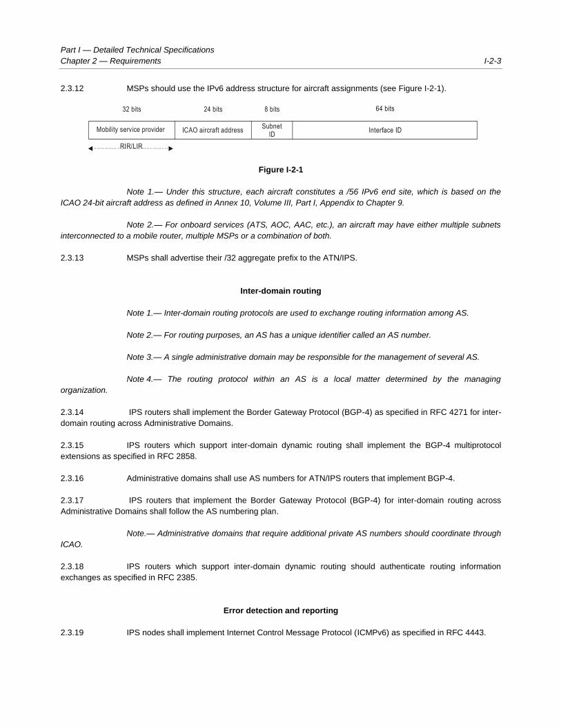
2.3.12 MSPs should use the IPv6 address structure for aircraft assignments (see Figure I-2-1).
Figure I-2-1
Note 1.— Under this structure, each aircraft constitutes a /56 IPv6 end site, which is based on the
ICAO 24-bit aircraft address as defined in Annex 10, Volume III, Part I, Appendix to Chapter 9.
Note 2.— For onboard services (ATS, AOC, AAC, etc.), an aircraft may have either multiple subnets
interconnected to a mobile router, multiple MSPs or a combination of both.
2.3.13 MSPs shall advertise their /32 aggregate prefix to the ATN/IPS.
Inter-domain routing
Note 1.— Inter-domain routing protocols are used to exchange routing information among AS.
Note 2.— For routing purposes, an AS has a unique identifier called an AS number.
Note 3.— A single administrative domain may be responsible for the management of several AS.
Note 4.— The routing protocol within an AS is a local matter determined by the managing
organization.
2.3.14 IPS routers shall implement the Border Gateway Protocol (BGP-4) as specified in RFC 4271 for inter-
domain routing across Administrative Domains.
2.3.15 IPS routers which support inter-domain dynamic routing shall implement the BGP-4 multiprotocol
extensions as specified in RFC 2858.
2.3.16 Administrative domains shall use AS numbers for ATN/IPS routers that implement BGP-4.
2.3.17 IPS routers that implement the Border Gateway Protocol (BGP-4) for inter-domain routing across
Administrative Domains shall follow the AS numbering plan.
Note.— Administrative domains that require additional private AS numbers should coordinate through
ICAO.
2.3.18 IPS routers which support inter-domain dynamic routing should authenticate routing information
exchanges as specified in RFC 2385.
Error detection and reporting
2.3.19 IPS nodes shall implement Internet Control Message Protocol (ICMPv6) as specified in RFC 4443.
Mobility service provider
RIR/LIR
SubnetID
Interface IDICAO aircraft address
32 bits 24 bits 8 bits 64 bits

I-2-4 Manual on the ATN using IPS Standards and Protocols
Quality of Service (QoS)
2.3.20 Administrative domains shall make use of differentiated services (DiffServ) as specified in RFC 2475
as a means to provide Quality of Service (QoS) to ATN/IPS applications and services.
2.3.21 Administrative domains shall enable ATN/IPS DiffServ class of service to meet the operational and
application requirements.
2.3.22 Administrative domains supporting voice-over IP services shall assign those services to the expedited
forwarding (EF) per-hop behavior (PHB) as specified in RFC 3246.
2.3.23 Administrative domains shall assign ATN application traffic to the assured forwarding (AF) PHB as
specified in RFC 2597.
Note.— Assured forwarding allows the ATN/IPS operator to provide assurance of delivery as long as
the traffic does not exceed the subscribed rate. Excess traffic has a higher probability of being dropped if congestion
occurs.
2.3.24 Administrative domains that apply measures of priority to the AF PHBs shall assign relative measures
based on the ATN mapping of priorities defined in Annex 10, Volume III, Part I, Chapter 3, Table 3-1.
IP version transition
2.3.25 Administrative domains should use the dual IP layer mechanism for IPv6 to IPv4 compatibility as
described in RFC 4213.
Note.— This provision ensures that ATN/IPS hosts also support IPv4 for backward compatibility with
local IPv4 applications.
2.4 TRANSPORT LAYER REQUIREMENTS
Transmission control protocol (TCP)
2.4.1 IPS hosts requiring connection-oriented transport service shall implement the Transmission Control
Protocol (TCP) as specified in RFC 793.
2.4.2 IPS nodes may implement TCP extensions for high performance as specified in RFC 1323.
User datagram protocol (UDP)
2.4.3 IPS hosts requiring connectionless transport service shall implement the User Data Gram Protocol
(UDP) as specified in RFC 768..
Transport protocol port numbers
2.4.4 IPS nodes shall support and make use of the TCP and/or UDP port numbers defined in Part II, 2.1.1.2,

Part I — Detailed Technical Specifications
Chapter 2 — Requirements I-2-5
2.1.2.3 and 2.3.2 of this document.
2.5 SECURITY REQUIREMENTS
Note.— The use of the following security requirements for communications in the ATN/IPS should be
based on a system threat and vulnerability analysis.
2.5.1 This section defines IPS node security requirements and capabilities but does not impose their use for
communications in the ATN/IPS.
Ground-ground security
Note.— IP layer security in the ground-ground ATN/IPS internetwork is implemented using Internet
protocol security (IPsec) and the Internet key exchange version 2 (IKEv2) protocol.
Ground-ground IPsec/IKEv2
2.5.2 IPS nodes in the ground-ground environment shall comply with the security architecture for the
Internet protocol as specified in RFC 4301.
2.5.3 IPS nodes in the ground-ground environment shall implement the IP encapsulating security payload
(ESP) protocol as specified in RFC 4303.
2.5.4 IPS nodes in the ground-ground environment may implement the IP authentication header (AH)
protocol as specified in RFC 4302.
2.5.5 IPS nodes in the ground-ground environment shall implement the Internet key exchange version
(IKEv2) protocol as specified in RFC 4306.
2.5.6 IPS nodes in the ground-ground environment shall implement the cryptographic algorithm
implementation requirements for the ESP and AH, if AH is implemented as specified in RFC 4835.
2.5.7 IPS nodes in the ground-ground environment shall implement the null encryption algorithm as
specified in RFC 4835, but not the null authentication algorithm, when establishing Internet protocol security (IPsec)
associations.
2.5.8 IPS nodes in the ground-ground environment shall implement the cryptographic algorithms for use in
the IKEv2 as specified in RFC 4307, when negotiating algorithms for key exchange.
2.5.9 IPS nodes in the ground-ground environment should use the Internet X.509 public key infrastructure
certificate and certificate revocation list (CRL) profile as specified in RFC 5280, when digital signatures are used as the
IKEv2 authentication method.
2.5.10 IPS nodes in the ground-ground environment should use the Internet X.509 public key infrastructure
ertificate policy and certificate practices framework as specified in RFC 3647, when digital signatures are used as the
IKEv2 authentication method.
Note.— The Air Transport Association (ATA) Digital Security Working Group (DSWG) has developed
a certificate policy (ATA Specification 42) for use in the aviation community. ATA Specification 42 includes certificate
and CRL profiles that are suitable for aeronautical applications and interoperability with an aerospace industry public key

I-2-6 Manual on the ATN using IPS Standards and Protocols
infrastructure (PKI) bridge. These profiles provide greater specificity than, but do not conflict with, RFC 5280.
Air-ground security
Air-ground access network security
2.5.11 IPS mobile nodes shall implement the security provisions of the access network to enable access
network security.
Note.— For example, the WiMAX, 3GPP, and 3GPP2 access networks have authentication and
authorization provisions.
Air-ground IPsec/IKEv2
2.5.12 IPS nodes in the air-ground environment shall comply with the security architecture for the Internet
protocol as specified in RFC 4301.
2.5.13 IPS nodes in the air-ground environment shall implement the IP ESP protocol as specified in
RFC 4303.
2.5.14 IPS nodes in the air-ground environment shall implement AUTH_HMAC_SHA2_256-128 as the
integrity algorithm for ESP authentication as specified in RFC 4868, when establishing IPsec security associations.
2.5.15 IPS nodes in the air-ground environment which implement encryption shall implement AES-GCM with
an 8 octet integrity check value (ICV) and with a key length attribute of 128 bits for ESP encryption and authentication as
specified in RFC 4106.
2.5.16 IPS nodes in the air-ground environment shall implement the IKEv2 protocol as specified in
RFC 4306.
2.5.17 IPS nodes in the air-ground environment shall implement IKEv2 with the following transforms:
a) PRF_HMAC_SHA_256 as the pseudo-random function as specified in RFC 4868.
b) 256-bit random encryption control protocol (ECP) group for Diffie-Hellman key exchange values
as specified in RFC 4753.
c) ECDSA with SHA-256 on the P-256 curve as the authentication method as specified in RFC
4754.
d) AES-CBC with 128-bit keys as the IKEv2 encryption transforms as specified in RFC 3602.
e) HMAC_SHA_256-128 as the IKEv2 integrity transform as specified in RFC 4868.
2.5.18 IPS nodes in the air-ground environment should use the Internet X.509 public key infrastructure
certificate and certificate revocation list (CRL) profile as specified in RFC 5280, when digital signatures are used as the
IKEv2 authentication method.
2.5.19 IPS nodes in the air-ground environment should use the Internet X.509 public key infrastructure
certificate policy and certificate practices framework as specified in RFC 3647, when digital signatures are used as the

Part I — Detailed Technical Specifications
Chapter 2 — Requirements I-2-7
IKEv2 authentication method.
Note.— The Air Transport Association (ATA) Digital Security Working Group (DSWG) has developed
a certificate policy (ATA Specification 42) for use in the aviation community. ATA Specification 42 includes certificate
and CRL profiles that are suitable for aeronautical applications and interoperability with an aerospace industry PKI
bridge. These profiles provide greater specificity than, but do not conflict with, RFC 5280.
2.5.20 IPS nodes in the air-ground environment, shall implement mobile IPv6 operation with IKEv2 and the
revised IPsec architecture as specified in RFC 4877.
Air-ground transport layer security
2.5.21 IPS mobile nodes and correspondent nodes may implement the transport layer security (TLS) protocol
as specified in RFC 5246.
2.5.22 IPS mobile nodes and correspondent nodes shall implement the cipher suite
TLS_ECDH_ECDSA_WITH_AES_128_CBC_SHA as specified in RFC 4492 when making use of TLS.
Air-ground application layer security
2.5.23 IPS mobile nodes and correspondent nodes may implement application layer security at the IPS
dialogue service boundary, which is specified in Part II, 1.4, of this document.
2.5.24 IPS mobile nodes and correspondent nodes shall append a keyed hashed message authentication
code (HMAC) as specified in RFC 2104 using SHA-256 as the cryptographic hash function, when application layer
security is used.
2.5.25 An HMAC tag truncated to 32 bits shall be computed over the user data concatenated with a 32-bit
send sequence number for replay protection, when application layer security is used.
2.5.26 IKEv2 shall be used for key establishment as specified in 2.5.12 to 2.5.20, when application layer
security is used.
2.6 PERFORMANCE
2.6.1 IPS nodes may implement RFC 2488 in order to improve performance over satellite links.
2.6.2 IPS nodes may implement the RObust header compression (ROHC) framework as specified in
RFC 4995 in order to optimize bandwidth utilization.
2.6.3 If ROHC is supported, then the following ROHC profiles shall be supported as applicable:
a) the ROHC profile for TCP/IP specified in RFC 4996;
b) the ROHC profile for real time transport protocol (RTP)/UDP/ESP specified in RFC 3095;
c) the IP-only ROHC profile specified in RFC 4843; and
d) the ROHC over point-to-point protocol (PPP) profile specified in RFC 3241.

I-2-8 Manual on the ATN using IPS Standards and Protocols
______________________
I-APP-1
APPENDIX to Part I
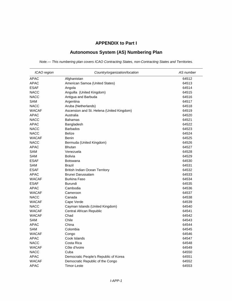
Autonomous System (AS) Numbering Plan
Note.— This numbering plan covers ICAO Contracting States, non-Contracting States and Territories.
ICAO region Country/organization/location AS number
APAC Afghanistan 64512
APAC American Samoa (United States) 64513
ESAF Angola 64514
NACC Anguilla (United Kingdom) 64515
NACC Antigua and Barbuda 64516
SAM Argentina 64517
NACC Aruba (Netherlands) 64518
WACAF Ascension and St. Helena (United Kingdom) 64519
APAC Australia 64520
NACC Bahamas 64521
APAC Bangladesh 64522
NACC Barbados 64523
NACC Belize 64524
WACAF Benin 64525
NACC Bermuda (United Kingdom) 64526
APAC Bhutan 64527
SAM Venezuela 64528
SAM Bolivia 64529
ESAF Botswana 64530
SAM Brazil 64531
ESAF British Indian Ocean Territory 64532
APAC Brunei Darussalam 64533
WACAF Burkina Faso 64534
ESAF Burundi 64535
APAC Cambodia 64536
WACAF Cameroon 64537
NACC Canada 64538
WACAF Cape Verde 64539
NACC Cayman Islands (United Kingdom) 64540
WACAF Central African Republic 64541
WACAF Chad 64542
SAM Chile 64543
APAC China 64544
SAM Colombia 64545
WACAF Congo 64546
APAC Cook Islands 64547
NACC Costa Rica 64548
WACAF Côte d'Ivoire 64549
NACC Cuba 64550
APAC Democratic People's Republic of Korea 64551
WACAF Democratic Republic of the Congo 64552
APAC Timor-Leste 64553

I-APP-2 Manual on the ATN using IPS Standards and Protocols
ICAO region Country/organization/location AS number
ESAF Djibouti 64554
NACC Dominica 64555
NACC Dominican Republic 64556
APAC Easter Island (Chile) 64557
SAM Ecuador 64558
MID Egypt 64559
NACC El Salvador 64560
WACAF Equatorial Guinea 64561
ESAF Eritrea 64562
ESAF Ethiopia 64563
SAM Falklands Islands (United Kingdom) 64564
NACC French Antilles 64565
WACAF Gabon 64566
WACAF Gambia 64567
WACAF Ghana 64568
NACC Grenada 64569
APAC Guam (United States) 64570
NACC Guatemala 64571
WACAF Guinea 64572
WACAF Guinea-Bissau 64573
SAM Guyana 64574
SAM French Guiana 64575
NACC Haiti 64576
NACC Honduras 64577
APAC Hong Kong, China 64578
APAC Wallis and Futuna Islands (France) 64579
APAC India 64580
APAC Indonesia 64581
MID Iran, Islamic Republic of 64582
MID Iraq 64583
EUR/NAT Israel 64584
NACC Jamaica 64585
APAC Japan 64586
APAC Johnston Island (United States) 64587
MID Jordan 64588
ESAF Kenya 64589
MID Bahrain 64590
APAC Kingman Reef (United States) 64591
APAC Kiribati 64592
MID Kuwait 64593
ESAF Réunion (France) 64594
APAC Lao People's Democratic Republic 64595
MID Lebanon 64596
ESAF Lesotho 64597
WACAF Liberia 64598
MID Libyan Arab Jamahiriya 64599
APAC Macao, China 64600
ESAF Madagascar 64601
ESAF Malawi 64602
APAC Malaysia 64603

Part I — Detailed Technical Specifications
Appendix — Autonomous system (AS) numbering plan I-APP-3
ICAO region Country/organization/location AS number
APAC Maldives 64604
WACAF Mali 64605
APAC Mariana Islands (United States) 64606
APAC Marshall Islands 64607
EUR/NAT Albania 64608
EUR/NAT Armenia 64612
EUR/NAT Austria 64616
EUR/NAT Azerbaijan 64620
EUR/NAT Belarus 64624
EUR/NAT Belgium 64628
EUR/NAT Bosnia and Herzegovina 64632
EUR/NAT Bulgaria 64636
EUR/NAT Croatia 64640
MID Cyprus 64644
EUR/NAT Czech Republic 64648
EUR/NAT Denmark 64652
EUR/NAT Estonia 64656
EUR/NAT Finland 64660
EUR/NAT France 64664
EUR/NAT Georgia 64668
EUR/NAT Germany 64672
EUR/NAT Greece 64676
EUR/NAT Hungary 64680
EUR/NAT Iceland 64684
EUR/NAT Ireland 64688
EUR/NAT Italy 64692
EUR/NAT Kazakhstan 64696
EUR/NAT Kyrgyzstan 64700
EUR/NAT Latvia 64704
EUR/NAT Liechtenstein 64706
EUR/NAT Lithuania 64708
EUR/NAT Luxembourg 64712
EUR/NAT The former Yugoslav Republic of Macedonia 64716
EUR/NAT Malta 64720
EUR/NAT Republic of Moldova 64724
EUR/NAT Monaco 64728
EUR/NAT Netherlands 64732
EUR/NAT Norway 64736
EUR/NAT Poland 64740
EUR/NAT Portugal 64744
EUR/NAT Romania 64748
EUR/NAT Russian Federation 64752
EUR/NAT Serbia 64756
EUR/NAT Slovakia 64760
EUR/NAT Slovenia 64764
EUR/NAT Spain 64768
EUR/NAT Sweden 64772
EUR/NAT Tajikistan 64776
EUR/NAT Switzerland 64780
EUR/NAT The Holy See 64782

I-APP-4 Manual on the ATN using IPS Standards and Protocols
ICAO region Country/organization/location AS number
EUR/NAT Turkey 64784
EUR/NAT Turkmenistan 64788
EUR/NAT Ukraine 64792
EUR/NAT United Kingdom 64796
EUR/NAT Uzbekistan 64800
EUR/NAT Algeria 64804
EUR/NAT Andorra 64808
EUR/NAT Gibraltar (United Kingdom) 64812
EUR/NAT Greenland (Denmark) 64816
EUR/NAT Montenegro 64820
EUR/NAT Morocco 64824
EUR/NAT San Marino 64828
EUR/NAT Tunisia 64832
EUR/NAT Regional - Europe 65108
EUR/NAT Regional - Europe 65112
EUR/NAT EUROCONTROL 65208
EUR/NAT EUROCONTROL 65212
EUR/NAT EUROCONTROL 65216
EUR/NAT EUROCONTROL 65220
EUR/NAT EUROCONTROL 65224
EUR/NAT EUROCONTROL 65228
EUR/NAT EUROCONTROL 65232
EUR/NAT EUROCONTROL 65236
WACAF Mauritania 65237
ESAF Mauritius 65238
NACC Mexico 65239
APAC Micronesia, Federated States of 65240
APAC Midway (United States) 65241
APAC Mongolia 65242
NACC Montserrat (United Kingdom) 65243
ESAF Mozambique 65244
APAC Myanmar 65245
ESAF Namibia 65246
APAC Nauru 65247
APAC Nepal 65248
NACC Netherlands Antilles 65249
APAC New Caledonia (France) 65250
APAC New Zealand 65251
NACC Nicaragua 65252
WACAF Niger 65253
WACAF Nigeria 65254
APAC Niue (New Zealand) 65255
MID Oman 65256
APAC Pakistan 65257
APAC Palau 65258
Palestinian Territory, occupied 65259
APAC Palmyra (United States) 65260
SAM Panama 65261
APAC Papua New Guinea 65262
SAM Paraguay 65263

Part I — Detailed Technical Specifications
Appendix — Autonomous system (AS) numbering plan I-APP-5
ICAO region Country/organization/location AS number
SAM Peru 65264
APAC Philippines 65265
APAC Pitcairn Island (United Kingdom) 65266
APAC French Polynesia 65267
NACC Puerto Rico (United States) 65268
MID Qatar 65269
APAC Republic of Korea 65270
APAC Fiji 65271
ESAF Rwanda 65272
NACC Saint Kitts and Nevis 65273
NACC Saint Lucia 65274
NACC Saint Vincent and the Grenadines 65275
APAC Samoa 65276
WACAF Sao Tome and Principe 65277
MID Saudi Arabia 65278
WACAF Senegal 65279
ESAF Seychelles 65280
WACAF Sierra Leone 65281
APAC Singapore 65282
APAC Solomon Islands 65283
ESAF Somalia 65284
ESAF South Africa 65285
APAC Sri Lanka 65286
MID Sudan 65287
SAM Suriname 65288
ESAF Swaziland 65289
MID Syrian Arab Republic 65290
APAC Thailand 65291
WACAF Togo 65292
APAC Tonga 65293
NACC Trinidad and Tobago 65294
NACC Turks and Caicos Islands (United Kingdom) 65295
APAC Tuvalu 65296
ESAF Uganda 65297
ESAF Comoros 65298
MID United Arab Emirates 65299
ESAF United Republic of Tanzania 65300
NACC United States 65301
SAM Uruguay 65302
APAC Vanuatu 65303
APAC Viet Nam 65304
NACC British Virgin Islands (United Kingdom) 65305
NACC Virgin Islands (United States) 65306
APAC Wake Island (United States) 65307
Western Sahara 65308
MID Yemen 65309
ESAF Zambia 65310
ESAF Zimbabwe 65311
______________________

Part II
Internet Protocol Suite (IPS) Applications

II-1-1
Chapter 1
INTRODUCTION
1.1 OBJECTIVE
This chapter describes how legacy ATN applications can make use of the ATN/IPS. The Legacy ATN applications are
defined in the Manual on Detailed Technical Specifications for the Aeronautical Telecommunication Network (ATN)
using ISO/OSI standards and protocols (Doc 9880), edition 2010. The ATN applications described in Doc 9880 specify
the use of the ATN/OSI layers for communication services. This chapter describes how those applications make use of
the ATN/IPS with minimal impact on the applications themselves.
1.3 GROUND DATA APPLICATIONS
ATS message handling services (ATSMHS)
Note 1.— The ATSMHS application aims to provide generic message services over the ATN.
Note 2.— IPS hosts that support the ATSMHS application shall comply with Doc 9880, Part II, edition
2010.
1.3.1 To operate ATSMHS over ATN/IPS, IPS hosts shall:
a) make use of RFC 2126 to directly provide TCP/IPv6 interface; or
b) make use of RFC 1006 to provide a TCP/IPv4 interface combined with IPv4/IPv6 protocol
translation device(s).
1.3.2 IPS hosts that support the ATSMHS application shall make use of TCP port number 102 as specified
in RFC 1006 and RFC 2126.
ATS interfacility data communications (AIDC)
Note 1.— The AIDC application, as defined in the Manual of Air Traffic Services Data Link
Applications (Doc 9694), exchanges information between ATS units (ATSUs) that support critical air traffic control (ATC)
functions, such as the notification of flights approaching a flight information region (FIR) boundary, the coordination of
boundary conditions and the transfer of control and communications authority.
Note 2.— The AIDC is currently not planned for implementation in the ATN/IPS environment.

II-1-2 Manual on the ATN using IPS Standards and Protocols
1.3.3 IPS hosts in the ATN that support the AIDC application exchanges may make use of the equivalent
operational application described in the EUROCONTROL specifications for On-Line Data Interchange (OLDI).
1.3.4 IPS hosts in the ATN that support the OLDI application shall make use of the EUROCONTROL
specifications for the flight message transfer protocol to operate the application over IPv6.
1.3.5 IPS hosts in the ATN that support the EUROCONTROL flight message transfer protocol shall make
use of TCP port number 8500.
1.4 AIR-GROUND DATA APPLICATIONS
Dialogue service
1.4.1 The dialogue service (DS), as documented in Doc 9880, Part III, edition 2010 serves as an interface
between the ATN applications and the ATN/OSI upper layer protocols via the control function. In order to minimize the
impact on the ATN applications, a new dialogue service was developed to support application implementation over the
ATN/IPS. This section specifies a replacement for the ATN/OSI DS interface to the upper layers, and is named the IPS
DS.
1.4.2 The IPS DS maps TCP/UDP primitives to the ATN application DS interface as depicted in
Figure II-1-1.
Figure II-1-1. ATN IPS upper layers diagram
1.4.3 Primitives from the ATN/OSI DS will be mapped as detailed in the following sections. This mapping is
used as a substitute for the upper layer communications service (ULCS) specification in Doc 9880, Part III.
1.4.4 The aeronautical telecommunication network packet (ATNPKT) header format defined in 1.4.11 to
1.4.15 describes a dedicated format designed to accommodate the passing of ATN application data over the ATN/IPS.
Either TCP or UDP may be used with the ATNPKT header format.
Controller-pilot data link communications (CPDLC), automatic dependent surveillance (ADS)
and flight information services (FIS)
Application user
ATN-App ASE
TCP/UDP
IPS DS

Part II — Internet Protocol Suite (IPS) Applications
Chapter 1 — Introduction II-1-3
1.4.5 IPS hosts that support ATN/OSI CPDLC, ADS and FIS applications shall use the IPS DS instead of
the DS defined in Doc 9880.
Context management (CM)
1.4.6 IPS hosts that support the ATN CM application shall support extensions of its abstract syntax notation
(ASN) as described in Part III, 1.4.39, of this document.
Note 1.— This is in order to allow passing the new IPS addressing information contained in the
updated CM application abstract syntax notation one (ASN.1).
Note 2.— The CM application is also known as the data link initiation capability (DLIC) service.
Note 3.— It is expected that a later edition of Doc 9880 will include these extensions taking
precedence over those specified in this document.
ATN/IPS dialogue service primitives
Note.— In order to retain commonality with the ULCS dialogue service primitives described in
Doc 9880, the IPS DS uses the same primitive names.
1.4.7 IPS nodes that support the DS functionality shall exhibit the behaviour defined by the service
primitives in Tables II-1-1 and II-1-2.
Table II-1-1. Dialogue service primitives
Service Description
D-START This is a confirmed service used to establish the binding between the communicating DS-users.
D-DATA This unconfirmed service is used by a DS-user to send a message from that DS-user to the peer
DS-user.
D-END This is a confirmed service used to provide the orderly unbinding between the communicating
DS-users, such that any data in transit between the partners is delivered before the unbinding
takes effect.
D-ABORT This unconfirmed service can be invoked to abort the relationship between the communicating
DS-users. Any data in transit between them may be lost.
D-P-ABORT This unconfirmed service is used to indicate to the DS-user that the dialogue service provider
has aborted the relationship with the peer DS-user. Any data in transit between the
communicating DS-users may be lost.
D-UNIT-DATA This unconfirmed service is used to send a single data item from one peer DS-user to another.
Any problem in delivering the data item to the recipient will not be signalled to the originator. This
service is specified in Table II-1-7.
Table II-1-2. Parameters of the dialogue service primitives

II-1-4 Manual on the ATN using IPS Standards and Protocols
Service Parameters
D-START Called peer ID
Called sys-ID
Called presentation address
Calling peer ID
Calling sys-ID
Calling presentation address
DS-user version number
Security requirements
Quality-of-Service
Result
Reject source
User data
D-DATA User data
D-END Result
User data
D-ABORT Originator
User data
D-P-ABORT (no parameters)
Note.— The parameters of the DS primitives are mapped to either the IP header, a field of the
transport protocol header, or as transport data in the ATNPKT format defined in 1.4.11 to 1.4.15.
Dialogue service definition
Sequence of primitives
1.4.8 IPS nodes that support the DS functionality shall allow peer communicating DS-users to:
a) establish a dialogue;
b) exchange user data;
c) terminate a dialogue in an orderly or abnormal fashion;
d) be informed of DS abnormal dialogue termination due to the underlying communication failure;
and
e) be consistent with the appropriate use of the corresponding service primitives.
1.4.9 Either DS-user may send data at any time after the initial D-START exchange, by using the D-DATA
service. Under normal circumstances, a dialogue is released by a DS-user invoking the D-END service. A dialogue is
abnormally released with the D-ABORT service. If the underlying service provider abnormally releases the dialogue, the
DS-users are notified with the D-P-ABORT service indication.

Part II — Internet Protocol Suite (IPS) Applications
Chapter 1 — Introduction II-1-5
1.4.10 It is only valid for the DS-user to issue and receive primitives for a “dialogue” in the sequence specified
in Table II-1-3. The table cells containing “Y” indicate valid primitives which may follow the DS primitive column
headings. For example, only “D-START ind” can follow the “D-END cnf” primitive.
Table II-1-3. Sequence of DS primitives for one dialogue at one DS-user
The DS primitive → D-START D-DATA D-END D-ABORT D-P-ABORT
May be followed by the DS primitive Y req cnf ind rsp req ind req cnf ind rsp req ind ind
1 D-START req
2 D-START cnf (accepted) Y
3 D-START ind Y Y Y Y Y
4 D-START rsp (accepted) Y
5 D-DATA req Y Y Y Y Y
6 D-DATA ind Y Y Y Y Y
7 D-END req Y Y Y Y
8 D-END cnf (accepted) Y
9 D-END ind Y Y Y Y
10 D-END rsp (accepted) Y
11 D-ABORT req Y Y Y Y Y Y Y Y
12 D-ABORT ind Y Y Y Y Y Y Y Y
13 D-P-ABORT ind Y Y Y Y Y Y Y Y
ATNPKT format
1.4.11 The purpose of the ATNPKT is to convey information between peer DS-users during the processing of
a DS primitive. It is carried in the data part of the transport protocol (either TCP or UDP). It is used to convey parameters
of the service primitives that cannot be mapped to existing IP or transport header fields. The ATNPKT will also convey
information to indicate the DS protocol function (e.g. the type of DS primitive).
1.4.12 In order to provide the most efficient use of bandwidth, a variable length format is used. The variable
length format will allow optimized processing of the DS primitive. This is an important issue when operating over narrow
band or costly air-ground communication links.
1.4.13 The ATNPKT format contains two parts:
— a fixed part that is present regardless of the DS primitive; and
— a variable part for optional fields.
1.4.14 The presence of optional parameters is indicated by setting bits within the fixed part of the ATNPKT.
These bits are referred to as “presence flags” and form the “presence field”. The position of an optional parameter in the

II-1-6 Manual on the ATN using IPS Standards and Protocols
variable part is determined by its position in the presence field. The ATNPKT format is shown in Figure II-1-2.
Figure II-1-2. ATNPKT format
1.4.15 The optional parameter representation, in the variable part of the ATNPKT, will be determined by the
parameter definition. Parameters of variable length will be represented in the LV format (i.e. length + value). Fixed length
parameters will be represented by their value.
ATNPKT fields
1.4.16 ATNPKT field formats are described using the convention (<bits> /<provider> / <usage>) where:
— <bits> indicates the size in bits of the field value (excluding length for LV parameters);
— <provider> indicates whether the value is provided by the DS-user as a primitive parameter
(external) or assigned by the DS-provider (internal);
— <usage> indicates whether or not the DS-user is to submit a value when invoking the
corresponding primitive parameter (optional vs. mandatory).
Fixed part of ATNPKT
ATNPKT version
Note.— The ATNPKT version indicates the version of the ATNPKT header.
1.4.17 The ATNPKT version shall be set to 1 and have a format of 4 bits / internal / mandatory.
Note 1.— The ATNPKT version is a number that will increment for any subsequent modifications to
the ATNPKT.
Note 2.— Reserving 4 bits will allow for up to 15 versions.
Note 3.— This field is not exposed at the DS-user’s level; it will be set by the DS-provider.
DS primitive
Note.— The DS primitive field is set by the DS-provider to indicate the type of DS primitive in the
packet.
ATNPKT
version
DS
primitive
App tech
type mo
re
Presence flags
Variable part
24
Fixed part
0 168
0
0 1 2 3 4 5 6 7 8 9 10 11

Part II — Internet Protocol Suite (IPS) Applications
Chapter 1 — Introduction II-1-7
1.4.18 The DS primitive field shall take one of the values specified below and have a format of 4 bits /
internal / mandatory:
Value Assigned DS primitive
1 D-START
2 D-START cnf
3 D-END
4 D-END cnf
5 D-DATA
6 D-ABORT
7 D-UNIT-DATA
8 D-ACK
9 D-KEEPALIVE
Note 1.— Reserving 4 bits will give provision for up to 16 protocol elements, allowing up to 7 additional
primitives to be defined.
Note 2.— The D-P-ABORT is not listed, as it is not sent end-to-end. Upon receipt of an abnormal
event or expiration of an inactivity timer, a D-P-ABORT will be indicated to the DS-user.
Application technology type
Note.— The application technology type identifies the type of application information that is being
carried. Other applications may also take advantage of the IPS infrastructure, e.g. FANS-1/A, ACARS, etc.
1.4.19 The application technology type shall be set to a value of b000 to indicate “ATN/IPS DS” and have a
format of 3 bits / internal / mandatory.
1.4.20 The application techinolgy type shall be set to a value ofr b011 to indicate “FANS/IPS DS” and have a
format of 3bits / internal / mandatory
Note.— The use or definition of other values is outside the scope of this manual.
The more bit
Note.— The more bit will be used for segmentation and reassembly of UDP datagrams; it is part of the
reliability mechanisms further described in 1.5.14.
1.4.20 The more bit shall be set to 0 to indicate a single or last segment; it shall be set to 1 to indicate the first
or intermediate segment and have a format of 1 bit / internal / mandatory .
Presence field
Note.— The presence field is a series of presence flags (or bits) that indicate whether or not optional
fields are present in the variable part of the ATNPKT.
1.4.21 The presence field shall have a format of 12 bits / internal / mandatory.

II-1-8 Manual on the ATN using IPS Standards and Protocols
1.4.22 A presence flag shall be set to 0 to indicate the absence of an optional field; it shall be set to 1 to
indicate the presence of an optional field.
1.4.23 The optional field details shall comply with Table II-1-4.
Table II-1-4. Presence field details
Bit Optional field Size (in bits) Format1 Description
0 Source ID 16 V DS connection identifier of the sender
1 Destination ID 16 V DS connection identifier of the recipient
2 Sequence numbers 8 V Sequence numbers (Ns, Nr)
3 Inactivity time 8 V Inactivity timer value of the sender (in minutes)
4 Called peer ID 24 to 64 (+8) LV2 Called peer ID (provided by the local DS-user)
5 Calling peer ID 24 to 64 (+8) LV2 Calling peer ID (provided by the local DS-user)
6 Content version 8 V Version of the application data carried
7 Security indicator 8 V Security requirements:
0 – no security (default value)
1 – Secured dialogue supporting key management
2 – Secured dialogue
3 … 255 – reserved
8 Quality of Service 8 V ATSC routing class:
0 – no traffic type policy preference
1 – “A”
2 – “B”
3 – “C”
4 – “D”
5 – “E”
6 – “F”
7 – “G”
8 – “H”
9 … 255 – reserved
9 Result 8 V Result of a request to initiate or terminate a dialogue:
0 – accepted (default value)
1 – rejected transient
2 – rejected permanent
3 … 255 – reserved
10 Originator 8 V Originator of the abort:
0 – user (default value)
1 – provider
2 … 255 – reserved
11 User data UDP: 0 to 8 1843 (+16)
TCP: variable size (+16)
LV2 User data (provided by the local DS-user)

Part II — Internet Protocol Suite (IPS) Applications
Chapter 1 — Introduction II-1-9
Note 1.— An optional field is present in the variable part when the corresponding bit is set in the
presence field and has one of the following formats:
— V = value; or
— LV = length (1 or 2 byte(s)) + value
Note 2.— The additional bits required for the length part of LV parameters is indicated between
brackets (in bits) in the third column of Table II-1-4.
Note 3.— Refer to 1.4.39 for details regarding the size of the user data parameter.
Variable parts of ATNPKT
Note.— The variable parts of the ATNPKT will be provided depending on the DS primitive being
invoked and the current state of the application using the IPS DS.
1.4.24 The position of an optional field in the variable part of the ATNPKT shall match the relative position of
its corresponding bit in the presence field (i.e. options are in the same order as the presence flags).
Source ID
Note.— The source ID identifies the DS connection at the sender side; it is part of the reliability
mechanisms, further described in 1.5.
1.4.25 The source ID shall be present in the D-START and D-START cnf primitives, and also when
D-ABORT is transmitted after D-START and before D-START cnf is received, and have a format of 16 bits / internal /
optional.
Destination ID
Note.— The destination ID identifies the connection at recipient side; it is part of the reliability
mechanisms, further described in 1.5.
1.4.26 The destination ID shall be present in the D-START cnf, D-DATA, D-END, D-END cnf, D-ABORT,
D-ACK and D-KEEPALIVE primitives and have a format of 16 bits / internal / optional.
Sequence numbers
Note.— The sequence numbers field contains the sequence numbers to be included in the ATNPKT.
This mechanism is used to detect the loss and the duplication of UDP datagrams; it allows implicit (i.e. the service
confirmation) or explicit acknowledgement (D-ACK). This field is part of the reliability mechanisms, further described in
1.5.
1.4.27 The sequence numbers field shall be present in all DS primitives over UDP and have the format
8 bits / internal / mandatory as detailed in Figure II-1-3.

II-1-10 Manual on the ATN using IPS Standards and Protocols
Figure II-1-3. Sequence number format
N(S) - [0…15] — sequence number of the ATNPKT sent.
N(R) - [0…15] — expected sequence number of the next ATNPKT to be received.
Note.— For D-ACK and D-KEEPALIVE, only the N(R) is meaningful on transmission.
1.4.28 When using sequence numbers with D-ACK and D-KEEPALIVE over UDP, the current value of the
send sequence number for N(S) may be used without subsequently incrementing it after transmission.
Inactivity time
Note.— The inactivity time indicates the time value (in minutes) of the inactivity timer at the sender
side. This field is used as part of the reliability mechanisms, further described in 1.5.
1.4.29 The inactivity time shall be optionally present in the D-START and D-START cnf primitives and have
the format 8 bits / internal / optional.
1.4.30 When this parameter is not provided by the DS-user, the default value of 4 minutes shall be used as
the inactivity timer by the source DS-provider.
Called peer ID
Note.— The called peer ID identifies the intended peer DS-user.
1.4.31 The called peer ID shall be either a 24-bit ICAO aircraft identifier or a 3–8 character ICAO facility
designation and have the format 24 to 64 bits / external / optional.
Calling peer ID
Note.— The calling peer ID identifies the initiating peer DS-user.
1.4.32 The calling peer ID shall be either a 24-bit ICAO aircraft identifier or a 3–8 character ICAO facility
designation and have the format 24 to 64 bits / external / optional.
Content version
Note.— The content version field is used to indicate the application’s version number.
1.4.33 The content version shall be the version of the ASN.1 syntax used for the user data field and have the
format 8 bits / external / optional.
N(S) N(R)

Part II — Internet Protocol Suite (IPS) Applications
Chapter 1 — Introduction II-1-11
Security indicator
Note 1.— The security indicator parameter is used to convey the level of security to be applied to the
dialogue. In Doc 9880, this field is referred to as “security requirements”; it is renamed here since “requirement” is not
really appropriate in this case. It is really an indication from the local DS-user of which kind of security procedure is to be
used to set up a secure dialogue exchange.
1.4.34 The security indicator parameter shall be one of the following values and have a format of 8 bits /
external / optional:
Value Security level
0 No security (default value)
1 Secured dialogue supporting
key management
2 Secured dialogue
3 – 255 Reserved
Note.— The absence of this parameter by the DS-user results in the security level being set to the
default value, i.e. no security.
Quality of Service
Note.— The Quality of Service (QoS) parameter is used to convey the DS-user QoS requirement
which is a value corresponding to the ATSC routing class and/or residual error rate (RER).
1.4.35 The QoS parameter shall have the following values and a format of 8 bits / external / optional:
1. The DS-user-provided ATSC routing class as below:
Value ATSC routing class description
0 No traffic type policy preference
1 “A”
2 “B”
3 “C”
4 “D”
5 “E”
6 “F”
7 “G”
8 “H”
9 – 255 Reserved

II-1-12 Manual on the ATN using IPS Standards and Protocols
2. The RER as defined below:
Value RER level
0 Low
1 Medium
2 High
3. ATN application priority may be indicated by inserting differentiated service codepoint (DSCP)
values in the IPv6 header as described in Part III, 1.5.9 and 1.5.10, of this document.
Note.— The priority is normally set by the network layer, so it is not necessary for the application to
provide one. The network layer can discern the priority by the port number being used or IP address and set the
differentiated service field accordingly. It should also be noted that the network management procedures may lead to
packet re-marking, regardless of the initial application indications, to be consistent with local network-differentiated
service definitions.
1.4.36 The UDP checksum may be activated for low or medium RER values and not activated for a high RER
value.
Note.— TCP checksums are always activated. The UDP checksums are activated by default.
Result
Note.— The result is set by the destination DS-user in order to indicate whether or not the requested
dialogue initiation or termination completed successfully.
1.4.37 The result shall have the format of 8 bits / external / mandatory and take one of the values below:
Value Definition
0 Accepted
1 Rejected (transient)
2 Rejected (permanent)
3 – 255 Reserved
Originator
Note.— The originator indicates the source of a D-ABORT.
1.4.38 The originator shall take one of the values below and the format of 8 bit / external / optional:
Value Definition
0 User (default)
1 Provider
2 – 255 Reserved
Note.— When this parameter is not provided by the DS-user, the default value is assumed.

Part II — Internet Protocol Suite (IPS) Applications
Chapter 1 — Introduction II-1-13
User data
Note.— The user data contains the packed encoding rules (PER) encoded application data.
1.4.39 The user data shall have the format of UDP: 0 to 8 184, TCP: variable size / external / optional.
Note 1.— The maximum user data size for a D-DATA service is the maximum UDP datagram size
(8 192 bytes) reduced by the size of the ATNPKT header (8 bytes). For other service primitives, the maximum user data
size needs to be adjusted based on the size of the fixed header part plus the size of the variable length parts for that
particular service primitive.
Note 2.— The IPS DS will segment UDP datagrams with user data that exceeds 1 024 bytes, as
described in 1.5.14, which will need to be reassembled by the receiver.
IPS DS parameter mapping
Note.— The IPS DS presents an identical interface of the ULCS to the ATN applications. As such, the
parameters of the IPS DS are identical to those of the ULCS. However, there is a different mapping of the contents of
those parameters. These modified mappings are summarized in Table II-1-5 and detailed for each primitive in
Table II-1-7.
Table II-1-5. IPS DS — ULCS DS parameter mapping
DS parameter
visible to the
DS-user IP header
Transport
protocol
header
ATNPKT
(See Table II-1-4) Comment
Called peer ID Called peer ID This can be an ICAO 24-bit aircraft address
or an ICAO facility designator (4 to 8
characters).
Called sys-ID Destination
port number
This is a registered port number assigned
to each ATN application (see 1.5.4).
Called presentation
address
Destination IP
address
IP address of the recipient ATN application.
Calling peer ID Calling peer ID This can be an ICAO 24-bit aircraft address
or an ICAO facility designator (4 to 8
characters).
Calling sys-ID Source port
number
Using TCP, this port number is dynamically
assigned by the transport protocol stack on
the client side. With UDP, this port number
typically has a static value which is the
same as the destination port number.
Calling presentation
address
Source IP
address
IP address of the originator of the ATN
application.
DS-user version
number
Content version This is the application’s version number.

II-1-14 Manual on the ATN using IPS Standards and Protocols
DS parameter
visible to the
DS-user IP header
Transport
protocol
header
ATNPKT
(See Table II-1-4) Comment
Security
requirements
Security
requirements
00 – No security
01 – Secured dialogue supporting key
management
02 – Secured dialogue
03 – Reserved
Quality of Service Quality of Service This parameter is to be transported only
when provided as “ATSC routing class”; the
RER and priority are not indicated end-to-
end but are optionally indicated to the IPS
DS and used locally.
Result Result 00 – Accepted
01 – Rejected (permanent)
02 – Rejected (transient)
Reject source 00 – Remote DS-user
01 – Local DS-provider
Provided locally in the confirmation
primitive only; not transferred end-to-end.
Originator Originator 0 – User
1 – Provider (default)
2-255 – Reserved
User data User data This is the packet encoding rules (PER)
encoded data provided by the application.
1.4.40 The inclusion of optional ATNPKT parameters for each DS protocol message shall comply with
Table II-1-6:
Table II-1-6. ATNPKT parameters for DS protocol messages
(O = optional, M = mandatory, – = precluded to use)
(1) Source ID is present if D-ABORT is sent after D-START and before D-START cnf is received.
(2) Destination ID is absent if D-ABORT is sent after D-START and before D-START cnf is received.
(3) For segmented messages, this parameter is present only in the first segment.
(4) For segmented messages, this parameter is present in all the segments.
(5) These primitives will always set the More bit to “0”.
Protocol message D-START D-START cnf D-DATA
D-UNIT-
DATA D-END D-END cnf D-ABORT D-ACK
D-
KEEPALIVE
Fixed part
ATNPKT version M M M M M M M M M
DS primitive M M M M M M M M M

Part II — Internet Protocol Suite (IPS) Applications
Chapter 1 — Introduction II-1-15
Protocol message D-START D-START cnf D-DATA
D-UNIT-
DATA D-END D-END cnf D-ABORT D-ACK
D-
KEEPALIVE
Application technology type M M M M M M M M M
More M M M M(5) M M M(5) M(5) M(5)
Presence flag M M M M M M M M M
Variable part
Source ID M (4) M (4) – – – – (1) – –
Destination ID – M (4) M (4) M (4) M (4) M (2) M M
Sequence numbers
UDP M (4)
TCP O(4)
UDP M (4)
TCP O(4)
UDP M (4)
TCP O(4)
UDP M
TCP O
UDP M(4)
TCP O(4)
UDP M (4)
TCP O (4)
UDP M
TCP O
UDP M
TCP O
UDP M
TCP O
Inactivity time O (3) O (3) – – – – – – –
Called peer ID O (3) – – O – – – – –
Calling peer ID O (3) – – O – – – – –
Content version O (3) O (3) – O – – – – –
Security indicator O (3) O (3) – O – – – – –
Quality of Service O (3) – – – – – – – –
Result – M (3) – – – M (3) – – –
Originator – – – – – – O – –
User data O (4) O (4) M (4) M O (4) O (4) O – –
Dialogue service primitives
Note.— In order to provide the services identified in 1.4.7, the primitives listed in Table II-1-7 are used.
Each primitive may be either directly exposed to the DS-user (request/response primitives) or reported to the DS-user by
the DS-provider (indication/confirmation primitives).
Table II-1-7. Dialogue service primitive details
Interface primitive Dialogue service description DS-user DS-provider
D-START req Request to initiate a dialogue with a peer DS-user
D-START ind Inform a local DS-user that a peer DS-user requested for a
dialogue initiation
D-START rsp Complete a pending dialogue initiation with either a positive
or a negative response
D-START cnf Inform a local DS-user that the peer DS-user completed the
pending dialogue initiation with either a positive or a negative
response
D-UNIT-DATA req Send a datagram from the local DS-user to a peer DS-user
(the end-to-end delivery of the datagram is not guaranteed)

II-1-16 Manual on the ATN using IPS Standards and Protocols
Interface primitive Dialogue service description DS-user DS-provider
D-UNIT-DATA ind Inform a local DS-user that a datagram is received from a
peer DS-user
D-DATA req Send a datagram from the local DS-user to a peer DS-user
over an established dialogue
D-DATA ind Inform a local DS-user that a datagram is received from a
peer DS-user over an established dialogue
D-END req Request to terminate a dialogue with a peer DS-user
D-END ind Inform a local DS-user that a peer DS-user requested a
dialogue termination
D-END rsp Complete a pending dialogue termination with either a
positive or a negative response
D-END cnf Inform a local DS-user that the peer DS-user completed the
pending dialogue termination with either a positive or a
negative response
D-ABORT req Request to abort a dialogue with a peer DS-user
D-ABORT ind Inform a local DS-user that the peer DS-user requested to
abort the dialogue
D-P-ABORT ind Dialogue aborted by the DS-provider
Dialogue service time-sequence diagrams
1.4.41 Figures II-1-4 to II-1-13 below illustrate the dialogue service protocol exchanges between source and
destination DS-providers, including the ATNPKT user data part.
Figure II-1-4. D-START service
D-START response
D-START indication
D-START requestD-START
Dialogue service
D-START cnf
D-START confirmation
Part II — Internet Protocol Suite (IPS) Applications
Chapter 1 — Introduction II-1-17
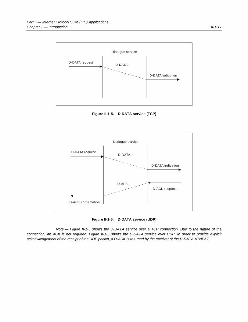
Figure II-1-5. D-DATA service (TCP)
Figure II-1-6. D-DATA service (UDP)
Note.— Figure II-1-5 shows the D-DATA service over a TCP connection. Due to the nature of the
connection, an ACK is not required. Figure II-1-6 shows the D-DATA service over UDP. In order to provide explicit
acknowledgement of the receipt of the UDP packet, a D-ACK is returned by the receiver of the D-DATA ATNPKT.
D-DATA indication
D-DATA requestD-DATA
Dialogue service
D-ACK response
D-DATA indication
D-DATA requestD-DATA
Dialogue service
D-ACK
D-ACK confirmation
II-1-18 Manual on the ATN using IPS Standards and Protocols
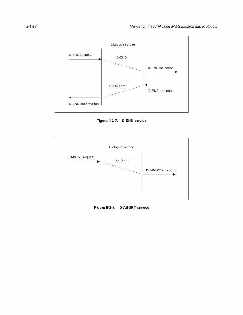
Figure II-1-7. D-END service
Figure II-1-8. D-ABORT service
D-END response
D-END indication
D-END requestD-END
Dialogue service
D-END cnf
D-END confirmation
D-ABORT indication
D-ABORT requestD-ABORT
Dialogue service

Part II — Internet Protocol Suite (IPS) Applications
Chapter 1 — Introduction II-1-19
Figure II-1-9. D-P-ABORT service
Note.— There is no ATNPKT format defined for the D-P-ABORT service, as it is a local indication to
the DS-user.
Figure II-1-10. D-UNIT-DATA service (TCP)
Dialogue service
D-P-ABORT indication D-P-ABORT indication
D-UNIT-DATA indication
D-UNIT DATA requestD-UNIT-DATA
Dialogue service
II-1-20 Manual on the ATN using IPS Standards and Protocols
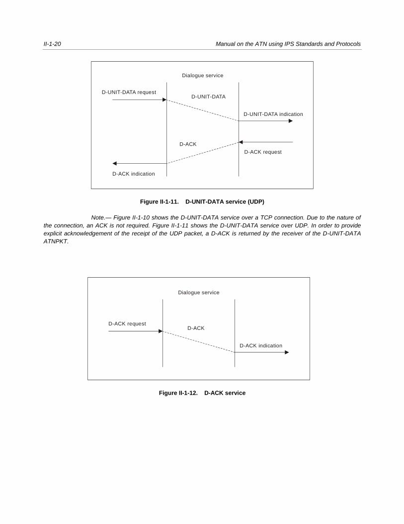
Figure II-1-11. D-UNIT-DATA service (UDP)
Note.— Figure II-1-10 shows the D-UNIT-DATA service over a TCP connection. Due to the nature of
the connection, an ACK is not required. Figure II-1-11 shows the D-UNIT-DATA service over UDP. In order to provide
explicit acknowledgement of the receipt of the UDP packet, a D-ACK is returned by the receiver of the D-UNIT-DATA
ATNPKT.
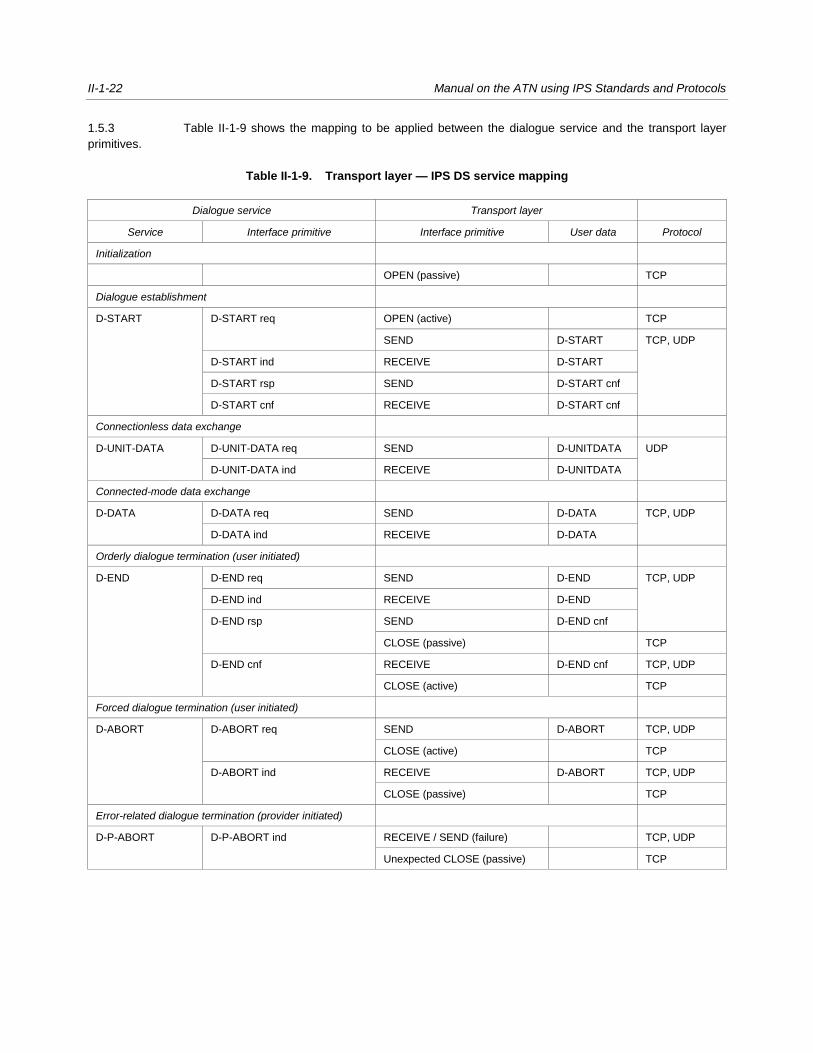
Figure II-1-12. D-ACK service
D-ACK request
D-UNIT-DATA indication
D-UNIT-DATA requestD-UNIT-DATA
Dialogue service
D-ACK
D-ACK indication
D-ACK indication
D-ACK requestD-ACK
Dialogue service

Part II — Internet Protocol Suite (IPS) Applications
Chapter 1 — Introduction II-1-21
Figure II-1-13. D-KEEPALIVE service
1.5 TRANSPORT LAYER
Overview
1.5.1 The IPS DS has been designed to allow a user to select either TCP or UDP for the transport protocol.
For simplicity, port-related operations are not considered as primitives.
1.5.2 The transport layer primitives are given in Table II-1-8.
Table II-1-8. Transport layer primitives used in the IPS DS
Transport layer
Interface primitive Description TCP UDP
OPEN Connection establishment (referred as “active” on initiator
side, “passive” on the other side)
CLOSE Connection termination (referred as “active” on initiator side,
“passive” on the other side)
RECEIVE Receive transport level datagram
SEND Send transport level datagram
D-KEEPALIVE indication
D-KEEPALIVE requestD-KEEPALIVE
Dialogue service
II-1-22 Manual on the ATN using IPS Standards and Protocols
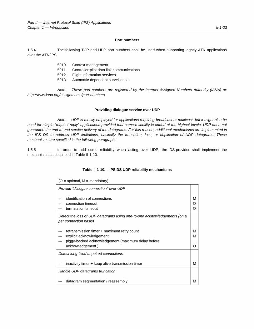
1.5.3 Table II-1-9 shows the mapping to be applied between the dialogue service and the transport layer
primitives.
Table II-1-9. Transport layer — IPS DS service mapping
Dialogue service Transport layer
Service Interface primitive Interface primitive User data Protocol
Initialization
OPEN (passive) TCP
Dialogue establishment
D-START D-START req OPEN (active) TCP
SEND D-START TCP, UDP
D-START ind RECEIVE D-START
D-START rsp SEND D-START cnf
D-START cnf RECEIVE D-START cnf
Connectionless data exchange
D-UNIT-DATA D-UNIT-DATA req SEND D-UNITDATA UDP
D-UNIT-DATA ind RECEIVE D-UNITDATA
Connected-mode data exchange
D-DATA D-DATA req SEND D-DATA TCP, UDP
D-DATA ind RECEIVE D-DATA
Orderly dialogue termination (user initiated)
D-END D-END req SEND D-END TCP, UDP
D-END ind RECEIVE D-END
D-END rsp SEND D-END cnf
CLOSE (passive) TCP
D-END cnf RECEIVE D-END cnf TCP, UDP
CLOSE (active) TCP
Forced dialogue termination (user initiated)
D-ABORT D-ABORT req SEND D-ABORT TCP, UDP
CLOSE (active) TCP
D-ABORT ind RECEIVE D-ABORT TCP, UDP
CLOSE (passive) TCP
Error-related dialogue termination (provider initiated)
D-P-ABORT D-P-ABORT ind RECEIVE / SEND (failure) TCP, UDP
Unexpected CLOSE (passive) TCP
Part II — Internet Protocol Suite (IPS) Applications
Chapter 1 — Introduction II-1-23
Port numbers
1.5.4 The following TCP and UDP port numbers shall be used when supporting legacy ATN applications
over the ATN/IPS:
5910 Context management
5911 Controller-pilot data link communications
5912 Flight information services
5913 Automatic dependent surveillance
Note.— These port numbers are registered by the Internet Assigned Numbers Authority (IANA) at:
http://www.iana.org/assignments/port-numbers
Providing dialogue service over UDP
Note.— UDP is mostly employed for applications requiring broadcast or multicast, but it might also be
used for simple “request-reply” applications provided that some reliability is added at the highest levels. UDP does not
guarantee the end-to-end service delivery of the datagrams. For this reason, additional mechanisms are implemented in
the IPS DS to address UDP limitations, basically the truncation, loss, or duplication of UDP datagrams. These
mechanisms are specified in the following paragraphs.
1.5.5 In order to add some reliability when acting over UDP, the DS-provider shall implement the
mechanisms as described in Table II-1-10.
Table II-1-10. IPS DS UDP reliability mechanisms
(O = optional, M = mandatory)
Provide “dialogue connection” over UDP
— identification of connections
— connection timeout
— termination timeout
M
O
O
Detect the loss of UDP datagrams using one-to-one acknowledgements (on a
per connection basis)
— retransmission timer + maximum retry count
— explicit acknowledgement
— piggy-backed acknowledgement (maximum delay before
acknowledgement )
M
M
O
Detect long-lived unpaired connections
— inactivity timer + keep alive transmission timer M
Handle UDP datagrams truncation
— datagram segmentation / reassembly M

II-1-24 Manual on the ATN using IPS Standards and Protocols
Connection-ids
1.5.6 A pair of connection-ids, the source ID and destination ID, shall be assigned during the connection
phase (D-START / D-START cnf) by every participating DS peer and used over any subsequent exchanges.
Note 1.— DS connection identification above the UDP layer will be handled by the assignment of this
pair of connection-ids.
Note 2.— The 2 byte size for these identifiers was chosen because this will allow the DS-provider to
associate a particular semantic to the dialogue-id assigned on its side (without interfering with the involved peer
DS-user). In such a case, the identifier might be an index in a context table, making it implicitly unique, but also allowing
the receiving DS-provider to find out the context without having to use multiple search criteria and parsing the whole
context table.
1.5.7 The source ID and destination ID shall be conveyed in the variable part of the ATNPKT based on DS
primitives as described in Table II-1-11:
Table II-1-11. Source ID and destination ID usage
(O = optional, M = mandatory)
DS primitive field Source ID Destination ID
D-START M Identifier given by the DS-
provider who initiates the
dialogue; it will allow the
user to find out the
dialogue context during
the whole dialogue
duration.
– Unassigned at this time
D-START cnf M Identifier given by the DS-
provider who accepts the
dialogue; it will allow the
provider to find out the
dialogue context during
the whole dialogue
duration.
M Identifier of the DS-provider who
initiated the dialogue.
D-DATA – No need to transport it
since it would be
meaningless for the
destination DS-provider.
M Identifier of the peer DS-provider.
D-END –- No need to transport it
since it would be
meaningless for the
destination DS-provider.
M Identifier of the peer DS-provider.
D-END cnf – No need to transport it
since it would be
meaningless for the
destination DS-provider.
M Identifier of the peer DS-provider.

Part II — Internet Protocol Suite (IPS) Applications
Chapter 1 — Introduction II-1-25
DS primitive field Source ID Destination ID
D-ABORT before
D-START cnf
M Identifier given by the DS-
provider who initiated the
dialogue.
– Unknown for now.
D-ABORT other cases – No need to transport it
since it would be
meaningless for the
destination DS-provider.
M Identifier of the peer DS-provider.
Detecting lost datagrams
Note 1.— The loss of UDP datagrams is detected through a one-to-one acknowledgement
mechanism, on a per DS connection basis, i.e. one data packet sent and one acknowledgement to be received before
more data can be sent again.
Note 2.— The acknowledgement may be piggy-backed with a dialogue message in the reverse
direction for the same dialogue; this will be possible for instance with confirmed primitives.
1.5.8 For unconfirmed DS services, the receiving user shall use an explicit acknowledgement by sending an
ATNPKT with no data and with a specific value (D-ACK) as “DS primitive”.
Note 1.— For acknowledgement purposes, the “sequence numbers” field of the ATNPKT variable part
will be used.
Note 2.— This sequence number is required to avoid delivering duplicated data to the peer DS-user
following retransmission (i.e. if a D-ACK has been lost), and in more exceptional circumstances, i.e. when UDP
datagrams are delivered out of sequence by the network.
1.5.9 The DS-provider shall associate an incremented sequence number to outgoing ATNPKTs and store
the sequence number of the last ATNPKT received from the peer DS-provider in order to acknowledge it in a
subsequent transmission.
1.5.10 Both outgoing and incoming sequence numbers shall be respectively carried by the N(S) and N(R)
subfields of the “sequence numbers”.
Note 1.— N(S) corresponds to the current sequence number of the ATNPKT that has been sent; N(R)
is the sequence number expected of the next ATNPKT to be received.
Note 2.— Using sequence numbers will allow the DS-provider to detect missing or duplicated
ATNPKTs. There is at most one unacknowledged ATNPKT; for this reason, there will be no grouped acknowledgements
and there is no need to implement a selective reject mechanism.
Note 3.— The lack of a timely acknowledgement will entail a retransmission. An excessive number of
retransmissions will break the DS connection. The timeout values and the maximum number of retransmissions are
detailed in Table II-1-12.

II-1-26 Manual on the ATN using IPS Standards and Protocols
Connection timeout
Note.— In order to avoid long-lived unpaired DS connections, a simple mechanism for detecting
inactivity is implemented. Both ends of the DS connection will transmit a keepalive packet when the “keepalive
transmission timer” expires. The keepalive transmission timer is restarted by the sender each time it sends data on the
connection, avoiding unnecessary keepalive transmissions.
1.5.11 A keepalive (an ATNPKT with no data and with a value of D-KEEPALIVE as DS primitive) shall be
sent at each expiry of the local keepalive transmission timer.
1.5.12 The keepalive transmission timer may be set to 1/3 of the inactivity timer of the peer DS-provider, or
1/3 of the default inactivity timer.
Note.— The lack of reception of either data or keepalive packets for an interval of time corresponding
to the inactivity time will break the DS connection. The parameter value for this time is detailed in Table II-1-12.
1.5.13 The optional ATNPKT field “inactivity time” may be used at dialogue initialization time (i.e. in D-START
and D-START cnf) so that each DS-provider can adjust its local keepalive transmission timer.
Note.— Absence of the inactivity time indicates use of the default inactivity time value as in
Table I-1-12.
“More” indicator
Note.— Most of the ATN application messages do not exceed 1 000 bytes. Additionally, the suggested
value of 1 024 bytes does not exceed the IP payload (1 500 bytes) in the Ethernet frame (1 518 bytes).
1.5.14 A D-DATA with a user data part exceeding 1 024 bytes shall be segmented using the more bit
reserved in the ATNPKT fixed part.
Note.— Upon receipt of a D-DATA with the more bit set, the receiving side is responsible for ordering
and reassembling the segmented data.
DS-provider parameters
1.5.15 The values specified in Table II-1-12 shall be applied to the identified DS-provider parameters:
Table II-1-12. DS-provider parameters
Parameter Minimum Maximum Default
Delay before retransmission 1 second 60 seconds 15 seconds
Maximum number of transmissions 1 10 3
Inactivity time 3 minutes 15 minutes 4 minutes

Part II — Internet Protocol Suite (IPS) Applications
Chapter 1 — Introduction II-1-27
1.6 IPS DIALOGUE SERVICE (DS) STATE TABLES
Table II-1-13. IPS DS state table for TCP
Events
State
D-IDLE D-CONNECTED D-START-SENT
D-START-
RECEIVED D-TRANSFER D-END-SENT
D-END-
RECEIVED
D-WAIT-
CLOSE
During initialization
phase
OPEN (passive)
DS
-use
r ev
ents
D-START req OPEN (active) -
Map D-START
req to D-START -
SEND (D-START)
- Enter D-START-
SENT state
D-START rsp Map D-START cnf
to D-START cnf -
SEND (D-START
cnf) - In case of
positive response
: - Start tinact -
Enter
D-TRANSFER
state - Otherwise :
-Enter D-WAIT-
CLOSE state
D-DATA req Map D-DATA req
to D-DATA -
SEND (D-DATA)
D-END req Cancel tinact - Map
D-END req to
D-END - SEND
(D-END) - Enter
D-END-SENT
state
D-END rsp Map D-END rsp to
D-END cnf -
SEND (D-END
cnf) -In case of
positive response
: -Enter D-WAIT-
CLOSE state -
Otherwise : - Start
tinact - Enter
D-TRANSFER
state
D-ABORT req Map D-ABORT
req to D-ABORT -
SEND (D-ABORT)
- Enter D-WAIT-
CLOSE state
Map D-ABORT
req to D-ABORT -
SEND (D-ABORT)
- Enter D-WAIT-
CLOSE state
Cancel tinact - Map
D-ABORT req to
D-ABORT - SEND
(D-ABORT) -
Enter D-WAIT-
CLOSE state
Map D-ABORT
req to D-ABORT -
SEND
(D-ABORT) -
Enter D-WAIT-
CLOSE state
Map D-ABORT
req to D-ABORT -
SEND
(D-ABORT) -
Enter D-WAIT-
CLOSE state
TC
P e
vent
s
OPEN (passive)
completed
Enter
D-CONNECTED
state
RECEIVE
(D-START)
Map D-START to
D-START ind -

II-1-28 Manual on the ATN using IPS Standards and Protocols
Events
State
D-IDLE D-CONNECTED D-START-SENT
D-START-
RECEIVED D-TRANSFER D-END-SENT
D-END-
RECEIVED
D-WAIT-
CLOSE
During initialization
phase
OPEN (passive)
Report D-START
ind to DS-User -
Enter D-START-
RECEIVED state
RECEIVE
(D-START cnf)
Map D-START cnf
to D-START cnf -
Report D-START
cnf to DS-user - In
case of positive
response : - Start
tinact - Enter
D-TRANSFER
state -
Otherwise : -
CLOSE (active) -
Enter D-IDLE
state
RECEIVE (D-
DATA)
Reset tinact - Map
D-DATA to
D-DATA ind -
Report D-DATA
ind to DS-user
RECEIVE (D-
END)
Cancel tinact - Map
D-END to D-END
ind - Report
D-END ind to DS-
user - Enter
D-END-
RECEIVED state
RECEIVE
(D-END cnf)
Map D-END cnf to
D-END cnf -
Report D-END cnf
to DS-user - In
case of positive
response : -
CLOSE (active) -
Enter D-IDLE
state - Otherwise :
- Start tinact - Enter
D-TRANSFER
state
TC
P e
vent
s
RECEIVE
(D-ABORT)
Map D-ABORT to
D-ABORT ind -
Report D-ABORT
ind to DS-user -
CLOSE (active) -
Enter D-IDLE
state
Cancel tinact - Map
D-ABORT to D-
ABORT ind -
Report D-ABORT
ind to DS-user -
CLOSE (active) -
Enter D-IDLE
state
Map D-ABORT to
D-ABORT ind -
Report D-ABORT
ind to DS-user -
CLOSE (active) -
Enter D-IDLE
state
Map D-ABORT to
D-ABORT ind -
Report D-ABORT
ind to DS-user -
CLOSE (active) -
Enter D-IDLE
state
CLOSE
(passive)
CLOSE (active) -
Enter D-IDLE
state
Report D-P-
ABORT ind to
DS-user - CLOSE
(active) -Enter
D-IDLE state
Report D-P-
ABORT ind to
DS-user - CLOSE
(active) -Enter
D-IDLE state
Cancel tinact -
Report D-P-
ABORT ind to
DS-User - CLOSE
(active) - Enter
D-IDLE state
Report D-P-
ABORT ind to
DS-user - CLOSE
(active) - Enter
D-IDLE state
Report D-P-
ABORT ind to
DS-user - CLOSE
(active) - Enter
D-IDLE state
CLOSE
(active) -
Enter D-IDLE
state

Part II — Internet Protocol Suite (IPS) Applications
Chapter 1 — Introduction II-1-29
Events
State
D-IDLE D-CONNECTED D-START-SENT
D-START-
RECEIVED D-TRANSFER D-END-SENT
D-END-
RECEIVED
D-WAIT-
CLOSE
During initialization
phase
OPEN (passive)
DS
-pro
vide
r ev
ents
tinact expires Report D-P-
ABORT ind to
DS-user - Enter
D-IDLE state
Table II-1-14. IPS DS state table for UDP
Events State
D-IDLE D-START-SENT D-START-RECEIVED D-TRANSFER D-END-SENT D-END-RECEIVED
DS
-use
r ev
ents
D-START req Map D-START req to
D-START - SEND
(D-START) - Start
tconnect - Enter
D-START-SENT state
D-START rsp Map D-START cnf to
D-START cnf - SEND
(D-START cnf) -In case
of positive response : -
Start tinact -Enter
D-TRANSFER state -
Otherwise : -Enter
D-IDLE state
D-DATA req Map D-DATA req to
D-DATA - SEND
(D-DATA)
D-END req Cancel tinact -Map
D-END req to D-END -
SEND (D-END) - start
tterm - Enter D-END-
SENT state
D-END rsp Map D-END rsp to
D-END cnf - SEND
(D-END cnf) - In case
of positive response : -
Enter D-IDLE state -
Otherwise : - Start tinact
- Enter D-TRANSFER
state
D-ABORT req Cancel tconnect -Map
D-ABORT req to
D-ABORT - SEND
(D-ABORT) - Enter
D-IDLE state
Map D-ABORT req to
D-ABORT - SEND
(D-ABORT) - Enter
D-IDLE state
Cancel tinact - Map
D-ABORT req to
D-ABORT - SEND
(D-ABORT) - Enter
D-IDLE state
Cancel tterm - Map
D-ABORT req to
D-ABORT - SEND
(D-ABORT) - Enter
D-IDLE state
Map D-ABORT req to
D-ABORT - SEND
(D-ABORT) - Enter
D-IDLE state

II-1-30 Manual on the ATN using IPS Standards and Protocols
Events State
D-IDLE D-START-SENT D-START-RECEIVED D-TRANSFER D-END-SENT D-END-RECEIVED
UD
P e
vent
s
RECEIVE (D-
START)
Map D-START to
D-START ind - Report
D-START ind to DS-
-user - Enter D-START-
RECEIVED state
RECEIVE (D-START
cnf)
Cancel tconnect -Map
D-START cnf to
D-START cnf - Report
D-START cnf to DS-
user -In case of positive
response : -Start tinact -
Enter D-TRANSFER
state - Otherwise : -
Enter D-IDLE state
RECEIVE (D-DATA) Reset tinact - Map
D-DATA to D-DATA ind
- Report D-DATA ind to
DS-user
RECEIVE (D-END) Cancel tinact -Map
D-END to D-END ind -
Report D-END ind to
DS-user - Enter
D-END-RECEIVED
state
RECEIVE (D-END
cnf)
Cancel tterm -Map
D-END cnf to D-END
cnf - Report D-END cnf
to DS-user - In case of
positive response : -
Enter D-IDLE state -
Otherwise : - Start tinact
- Enter D-TRANSFER
state
RECEIVE (D-
ABORT)
Map D-ABORT to
D-ABORT ind - Report
D-ABORT ind to DS-
user - Enter D-IDLE
state
Cancel tinact - Map
D-ABORT to D-ABORT
ind - Report D-ABORT
ind to DS-user - Enter
D-IDLE state
Cancel tterm - Map
D-ABORT to D-ABORT
ind - Report D-ABORT
ind to DS-user - Enter
D-IDLE state
Map D-ABORT to
D-ABORT ind - Report
D-ABORT ind to DS-
user - Enter D-IDLE
state
DS
eve
nts
tconnect expires Report D-P-ABORT ind
to DS-user - Enter
D-IDLE state
tinact expires Report D-P-ABORT ind
to DS-user - Enter
D-IDLE state
tterm expires Report D-P-ABORT ind
to DS-user - Enter
D-IDLE state
Part II — Internet Protocol Suite (IPS) Applications
Chapter 1 — Introduction II-1-31
Chapter 2
Internet Protocol-Based Applications
2.1 Telephony (VoIP)
Telephony ground applications shall be governed by EUROCAE document ED-137B, Interoperability
Standards for VoIP ATM Components, VOL 2 – Telephone, edition February 2012.
Note: ED-137B - Interoperability Standards for VoIP ATM Components, edition February 2012 is available on the
EUROCAE website at:
http://www.eurocae.net/
2.2 Air-Ground Radio (via VoIP)
Radio air-ground applications on the ground component shall be governed by EUROCAE document ED-137B,
Interoperability Standards for VoIP ATM Components, VOL 1 – Radio, edition February 2012.

II-1-32 Manual on the ATN using IPS Standards and Protocols
______________________

Part III
Guidance Material


III-1-1
CHAPTER 1
INTRODUCTION
1.1 GENERAL OVERVIEW
1.1.1 This part of the manual contains information to assist ICAO Contracting States in the deployment of an
ATN/IPS network to support air traffic management (ATM) services. The following minimum core services should be
provided by the ATN/IPS network.
1.1.2 These core services enable ATN applications to provide voice and data services using the appropriate
priority and security over the ATN/IPS network.
1.1.3 The protocols discussed in this document are based on the open system interconnection (OSI)
reference model. Figure III-1-1 depicts the relationship between OSI, ATN/OSI and the ATN/IPS protocols using the
4-layer model of the IETF.
Figure III-1-1. Protocol reference model
Application layer 7
Session layer 5
Transport layer 4
Network layer 3
Link layer 2
Physical layer 1
Presentation layer 6
OSI reference model
ATN/ISO protocols
ATN/IPS
Fast-byte
Fast-byte
ATN applications
(e.g. CMIP, X.400)
Transport layer
class 4
LLC/MAC
IPv6 and ICMPv6
TCP/UDP
Consolidated
application
services
(e.g. SMTP,
SNMPv3,
FTP, X.400
and Telnet)
LAP B (HDLC)
Physical layer
(e.g. EIA-232, V.35, X.21)
Physical layer
(e.g. FDDI, 802.X)
SNDCF
ES-IS/CLNP
X.25 PLP

III-1-2 Manual on the ATN using IPS Standards and Protocols
1.2 BACKGROUND
The ATN/IPS has been established with the specific goal of providing global ATM services based on commercial off-the-
shelf technologies. According to ICAO Standards and Recommended Practices (SARPs), ATN services can be provided
using the ISO-based ICAO protocols as specified in Doc 9705 and Doc 9880, or as specified in this manual. This manual
describes the technical approach for networking based on IPS, and will enable ICAO Contracting States to provide ATM
services on this basis.
1.3 GENERAL GUIDANCE
1.3.1 This section contains information about the implementation of ATN/IPS for ATN applications, multicast
and VoIP.
The ATN/IPS
The ATN/IPS internetwork
1.3.2 The ATN/IPS internetwork is specifically and exclusively intended to provide data communications
services to air traffic service (ATS) provider organizations and aircraft operating agencies supporting the following types
of communications traffic:
— ATS communication (ATSC). Communication related to air traffic services including air traffic
control, aeronautical and meteorological information, position reporting, and services related to
safety and regularity of flight. This communication involves one or more air traffic service
administrations.
— Aeronautical operational control (AOC). Communication required for the exercise of authority over
the initiation, continuation, diversion or termination of flight for safety, regularity and efficiency
reasons.
— Aeronautical administrative communication (AAC). Communication used by aeronautical
operating agencies in relation to the business aspects of operating their flights and transport
services. This communication is used for a variety of purposes, such as flight and ground
transportation, bookings, deployment of crew and aircraft or any other logistical purposes that
maintain or enhance the efficiency of overall flight operation.
1.3.3 In order to support these communications types, this manual specifies a set of technical and
administrative requirements upon the entities that constitute the ATN/IPS internetwork. See Figure III-1-2.
1.3.4 Technical requirements in this manual are levied against an IPS router, an IPS host, or an IPS node
when the requirement applies to both. This manual adopts the RFC 2460 definition of an IPS node as a device that
implements IPv6 and distinguishes between an IPS router as a node that forwards IP packets to others, and an IPS host
as a node that is not a router.
1.3.5 Administrative requirements in this manual are levied against administrative domains. An
administrative domain is an organizational entity which can be an individual State, a group of States (e.g. an ICAO
region or a regional organization), an air communications service provider (ACSP), an air navigation service provider
(ANSP), or other organizational entity that manages ATN/IPS network resources and services.

Part III — Guidance Material
Chapter 1 — Introduction III-1-3
Figure III-1-2. The ATN/IPS internetwork
1.3.6 The primary requirement is that each administrative domain participating in the ATN/IPS internetwork
must operate one or more IPS routers which execute an inter-domain routing protocol called the border gateway
protocol (BGP). This is essentially so that the ATN/IPS can be formed across the various administrative domains
whereby any IPS host can reach any other IPS host in the ATN/IPS internetwork.
1.3.7 An inter-domain routing protocol is used to exchange routing information among autonomous systems.
An autonomous system (AS), as defined in RFC 1930, is a connected group of one or more IP prefixes run by one or
more network operators which has a single and clearly defined routing policy. From this definition, there are two distinct
entities: one is the AS as a group of IP prefixes and the other is the network operators, i.e. the administrative domains.
This distinction is meaningful in the Internet since it permits multiple organizations (i.e. administrative domains) to run
BGP to an Internet service provider (ISP) which in turn connects each of these organizations to the Internet. This manual
does not preclude using ISPs in this fashion; however, as noted above, requirements are levied directly on the
administrative domains.
IPShost
IPShost
IPShost
IPShost
IPShost
IPShost
IPShost
IPShost
IPShost
IPSrouter
IPSrouter
IPSrouter
IPSrouter
IPSrouter
IPSrouter
IPSrouter
IPSrouter
IPSrouter
ATN/IPSinternetwork
ATN/IPSinternetwork
ATN/IPSinternetwork
ATN/IPSinternetwork
AD AD
AD
AD
AD
AD
AD
AD
AD
AD
AD
AD

III-1-4 Manual on the ATN using IPS Standards and Protocols
Coordination of policies among administrative domains
1.3.8 IPS routers will exchange information about their internal network prefixes with their immediate
neighbour routers, but may also forward routing information about other network prefixes learned from other BGP
neighbours. As a result, traffic between two administrative domains may be relayed by a number of intermediate
administrative domains. Such traffic being carried on behalf of two others is termed “transit traffic”.
1.3.9 This manual does not specify which routes are to be advertised between IPS routers nor basic traffic
management policies for a dynamically routed environment. Administrative domains, however, are required to
coordinate their policy for carrying transit traffic with peer administrative domains. Administrative domains that participate
in the ATN/IPS should ensure the proper handling of transit traffic on the following basis:
— an administrative domain should not advertise a network prefix if it is not prepared to accept
incoming traffic to that network prefix destination;
— when establishing the interconnections between two administrative domains a charging
mechanism may be agreed upon to support implicit corresponding transit policy; and
— administrative domains that relay transit traffic should ensure that the associated security and
QoS policies of the traffic are maintained.
ATN/IPS internetworking with mobility
1.3.10 The fixed or ground-ground ATN/IPS described in 1.3.2 to 1.3.7 may be extended to support mobility,
that is, it may be extended to support air-ground communications. This is accomplished through the use of mobile IPv6,
the IETF’s general mobility solution. Mobile IPv6 permits mobile nodes (MN) (i.e. aircraft in the ATN/IPS) to
communicate transparently with correspondent nodes (CN) (i.e. ground automation systems in the ATN/IPS) while
moving within or across air-ground networks. An administrative domain in the ATN/IPS which offers mobile IPv6 service
is called a mobility service provider (MSP). Thus, the ATN/IPS is extended to support mobility through the addition of
MSPs providing mobility service to mobile nodes. Figure III-1-3 depicts the ATN/IPS with an MSP. As is shown in this
figure, in order to provide mobility service, the MSP must operate one or more home agents. The home agent provides a
key role in that it provides location management (LM) to keep track of the movement of a mobile node and to locate the
mobile node for data delivery, while it also operates as an inter-domain router providing connectivity to the rest of the
ATN/IPS. (Note that this is a logical view. Different physical configurations are possible in actual implementations.) It
should be noted that mobile IPv6 RFC 3775 is being updated by the IETF (RFC 3775 bis). Implementation of RFC 3775
should take those updates into account.
1.3.11 Figure III-1-3 shows the minimal configuration, e.g. for ATSC, where the MSP might be an ACSP.
However, this is not the only possible configuration. An ANSP may choose to become its own MSP and obtain access
service from an ACSP. To support AOC and AAC an airline may likewise become an MSP. Similarly, an airport authority
may decide to become an MSP and offer service to the ATN/IPS. In this case, IP layer mobility service may be offered
along with or in addition to link layer mobility. As noted in 1.3.2 to 1.3.7, the ATN/IPS is intended to support ATSC, AAC
and AOC, however, the mobility approach may be used by other aviation organizations. These organizations may
become MSPs and support other types of communications such as airline passenger communications (APC). The
enhanced forms of Mobile IP listed in Sections 1.6.9, 1.6.10 and 1.6.11 may be offered to support all types of
communication traffic.
Network transition mechanisms
1.3.12 IPv6 has been adopted by the IETF and the Internet authorities to cope with the ever increasing
growth rate of the global Internet. IPv6 solves many of the technical problems associated with IPv4, in particular the
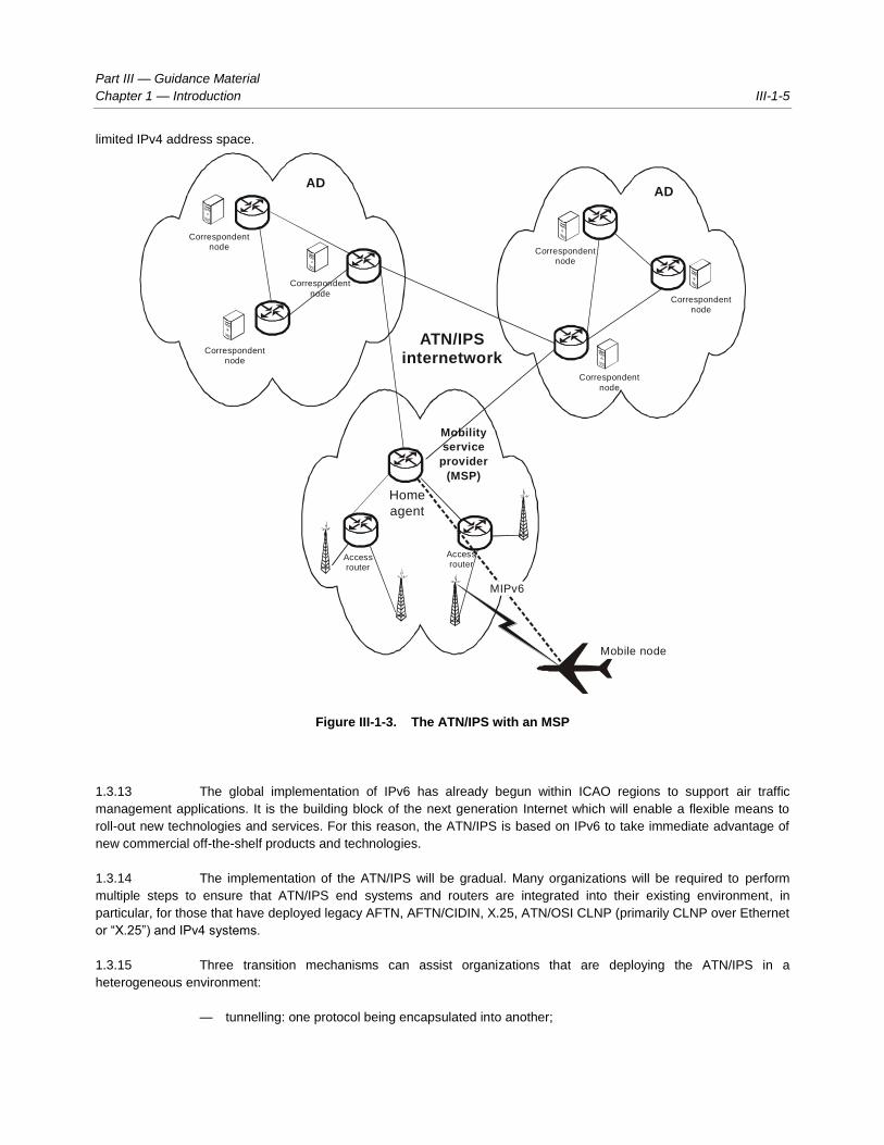
Part III — Guidance Material
Chapter 1 — Introduction III-1-5
limited IPv4 address space.
Figure III-1-3. The ATN/IPS with an MSP
1.3.13 The global implementation of IPv6 has already begun within ICAO regions to support air traffic
management applications. It is the building block of the next generation Internet which will enable a flexible means to
roll-out new technologies and services. For this reason, the ATN/IPS is based on IPv6 to take immediate advantage of
new commercial off-the-shelf products and technologies.
1.3.14 The implementation of the ATN/IPS will be gradual. Many organizations will be required to perform
multiple steps to ensure that ATN/IPS end systems and routers are integrated into their existing environment, in
particular, for those that have deployed legacy AFTN, AFTN/CIDIN, X.25, ATN/OSI CLNP (primarily CLNP over Ethernet
or “X.25”) and IPv4 systems.
1.3.15 Three transition mechanisms can assist organizations that are deploying the ATN/IPS in a
heterogeneous environment:
— tunnelling: one protocol being encapsulated into another;
AD
AD
Mobile node
Correspondentnode
Correspondentnode
Correspondent
node
Correspondent
node
Accessrouter
Accessrouter
Mobility
service
provider
(MSP)
Home
agent
Correspondentnode
Correspondentnode
ATN/IPS
internetwork
MIPv6

III-1-6 Manual on the ATN using IPS Standards and Protocols
— dual stack: an environment in which multiple protocols operate simultaneously; and
— translation: the conversion from one protocol to another.
1.3.16 An in-depth description of the first two mechanisms can be found in RFC 4213 (Basic Transition
Mechanisms for IPv6 Hosts and Routers). The applicability of the above three mechanisms to the ATN/IPS are further
described below.
Tunnelling
1.3.17 IPv6 has been specified to operate over a variety of lower layer interfaces such as Frame Relay, ATM,
HDLC, PPP and LAN technologies. Tunnelling implies that a given protocol is encapsulated into another, meaning that
IPv6 would be encapsulated into another functionally equivalent network protocol. With regard to the ATN/IPS, the key
benefit of this mechanism would be for aeronautical organizations that already operate IPv4 networks to allow the
ATN/IPS hosts and routers to communicate between each other over such an underlying IPv4 network. Furthermore, if
the interconnecting infrastructure between the two ATN/IPS administrative domains is limited to IPv4, this mechanism
can be applied.
1.3.18 It is recalled that IPv6 cannot operate over X.25; an IPv6 tunnel over IPv4 can be in turn tunnelled
over an X.25 network. A specific tunnelling mechanism termed IP SNDCF is defined for ATN/OSI applications, and it is
to be noted that this enables interoperability between ATN/OSI applications over an IP network but does not enable
interoperability with ATN/IPS applications.
1.3.19 Tunnelling mechanisms lead to an increase of protocol overhead and the segregation of the two
routed domains creates additional network management, e.g. an IPv6 routed domain over an underlying IPv4 routed
domain will need to be managed in terms of QoS, security, and route optimization. In addition, this mechanism only
foresees interoperability between ATN/IPS systems as it does not enable interoperability between ATN/OSI systems nor
other IPv4 systems within the organization. Nevertheless, it may provide an effective way to deploy the ATN/IPS within
and between two administrative domains.
1.3.20 The tunnelling mechanism is best suited to resolve lower layer communication issues between
ATN/IPS IPv6 hosts and routers; but it does not provide interoperability with non-compliant ATN/IPS systems.
Dual stack
1.3.21 The dual stack mechanism implies that an implementation handles more than one communications
protocol for a given application or function. Within the Internet domain a significant number of communication
applications have been dual stacked, e.g. HTTP, FTP, SSH, DNS, SMTP, by supporting both IPv4 and IPv6 protocols.
However, in the context of the ATN/IPS, the purpose of dual stacking is to resolve similar yet different issues.
1.3.22 The concept of dual stacking is ideally suited for systems that need to support ATN applications for
both OSI and IPS. In such environments, the applications are designed in an abstract fashion to be independent of the
lower layers, e.g. they are unaware which lower layer communications protocol (OSI or IP) is being used to
communicate with their peer. X.400 vendors have taken this approach to support both OSI and IP environments
avoiding the need to develop complex ad hoc lower layer communication gateways. Usually such implementations rely
on some form of directory or “lookup table” associating a high-level address with a specific communications protocol
address.
1.3.23 The concept of dual stacking can be extended to multiple stacking, e.g. IPv4, IPv6, X.25. ATN AMHS

Part III — Guidance Material
Chapter 1 — Introduction III-1-7
manufacturers usually support operation over multiple protocols such as OSI, TCP/IP and X.25.
1.3.24 The dual stack mechanism provides the maximum level of interoperability with peers while reducing
the complexity of lower layer communication protocol gateways and additional single points of failure. It is ideally suited
for applications such as the ATS message handling system (AMHS), whereby some systems have already been
implemented on the basis of OSI and others on TCP/IP. A dual stack approach can be valid for air-ground data link
ground systems to support CPDLC over multiple data link services, such as ATN/OSI and ATN/IPS.
Translation
1.3.25 Translation mechanisms imply the conversion from one protocol to another. This mechanism can be
interpreted as a lower layer communications gateway between two protocols that share a high degree of commonality.
Several translators such as RFC 2766 ─ Network Address Translation–Protocol Translation (NAT-PT), have been
developed in the context of the transition from IPv4 to IPv6 as both versions share a number of common features.
1.3.26 Within the overall transition from IPv4 to IPv6, it was envisaged that some systems may be only
capable of communicating with IPv4 while others only with IPv6. Considering global Internet scalability issues and the
fact that most Internet applications and systems have become dual stacked, the need for translators has declined.
1.3.27 However, translators may play an important short-term role in the case of the ATN/IPS. For example,
although existing AMHS systems operate on dual stack operating systems, none of them have upgraded their
application code to make use of IPv6. In other words, RFC 1006 is supported but not RFC 2126. In such particular cases
and in view of the limited number of systems, the deployment of translators provides a short-term measure for such
systems to comply with the ATN/IPS and interwork with RFC 2126 enabled systems.
1.3.28 IPv4/IPv6 translators increase the complexity of the IP infrastructure and its management. A dual
stack approach is to be preferred but in specific cases translators may be the only short-term measure to provide
compliance with the ATN/IPS.
Combining the mechanisms
1.3.29 As the ATN/IPS implementation will be gradual, it is understandable that a combination of the above
three mechanisms will be applied.
1.3.30 Specific combinations of the above mechanisms can be deployed to better fit within the environment
of the administrative domain environment.
1.4 PROTOCOL STACK
Physical and link layer guidance
1.4.1 Physical and link layer issues will be determined by the required service and Contracting State
connections. The physical and link layer issues will be on a service-need basis and should be contained in a
Memorandum of Agreement (MoA).
Network layer
1.4.2 The ATN/IPS makes use of IPv6, which uses 128 bit addresses versus 32 in IPv4. IPv6 prefixes are

III-1-8 Manual on the ATN using IPS Standards and Protocols
exchanged between administrative domains using static routes or BGP to ensure global ATN/IPS routing.
Address plan
1.4.3 Unlike IPv4, there is no notion of private addresses within IPv6. Similar to existing practices for X.25,
each administrative domain will be required to develop an IPv6 addressing plan (refer to Part I, 2.3.8 to 2.3.13, Network
addressing). This will involve the receipt of a unique IPv6 prefix and assignment procedures to networks and hosts.
Application interface to the network layer
1.4.4 Although applications generally interface to the communication service at the transport layer, it is
sometimes necessary to transmit and receive datagrams at the network level. This is granted by some socket API
extensions specified in RFC 3542 ─ Advanced Sockets Application Program Interface (API) for IPv6.
Inter-domain routing
1.4.5 Inter-domain routing allows the exchange of IPv6 prefixes between administrative domains. These
exchanges are supported by the configuration of static routing or the border gateway protocol (BGP) between ATN/IPS
routers to ensure global ATN/IPS routing.
1.4.6 Depending on the scale of the administrative domain, further internal levels of inter- and intra-domain
routing or BGP confederations may exist.
Autonomous systems (AS) numbering plan
1.4.7 AS numbers need to be assigned and configured in ATN/IPS routers to announce their autonomous
systems within the routed domain. The AS numbering plan is presented in the Appendix to Part I.
ATN/IPS router ids
1.4.8 In order to establish BGP between two neighbours, each BGP peer must define a router id. If two
routers make use of the same router-id value, BGP sessions cannot be established. As the router id is a 32-bit field, it is
usually on the IPv4 address of the router.
1.4.9 As ATN/IPS routers may not have IPv4 interfaces or unique IPv4 addresses, a scheme needs to be
recommended. Although global uniqueness of these values is not a prerequisite, to ease implementation of the ATN/IPS
the following scheme is recommended (based on draft-dupont-durand-idr-ipv6-bgp-routerid-01.txt):
— 4 bits set to one, 16 bits set to the AS number (the global AS number plan is in the Appendix to
Part I);
— 12 bits manually allocated within the domain (allows for 4 096 different router ids in each routing
domain).
Routing advertisement
1.4.10 ATN/IPS routers should advertise network prefixes based on consistent prefix lengths or aggregate
route prefixes.

Part III — Guidance Material
Chapter 1 — Introduction III-1-9
Traffic type segregation
1.4.11 BGP-4 does not natively allow setting up different sets of routes for different traffic types to the same
destination. ATN/IPS requirements on traffic type segregation may be fulfilled by appropriate provisions in the ATN
addressing plan; if the ATN address incorporates an indication of the traffic type, BGP-4 will transparently flood
segregated route information for the various traffic types.
Traffic priority and differentiated service
1.4.12 Historically, network layer priority was selected explicitly by sending an application through the type of
service (TOS) field in the IP header. Although differentiated services (RFC 2474) preserves the IP precedence semantic
of the TOS field, this approach is now deprecated. This is partly because the IP precedence has been superseded by
the per-hop behaviour (PHB) strategy of differentiated service, and also partly because network administrators usually
do not trust application settings. Differentiated service (RFC 2474) provides a means for specifying and implementing
QoS handling consistently in the ATN/IPS network. This specification is made on a per node basis, specifying behaviour
of individual nodes concerning QoS (PHB). The general framework/current practices is depicted in detail in RFC 2475 —
Architecture for Differentiated Services.
Note.— Refer to paragraph 4 — Quality of Service (QoS).
Multicast
1.4.13 The need to send the same information to multiple receivers is one of the main requirements of
surveillance data distribution. This requirement can be supported by IPv4 and IPv6 multicast services. Other networking
techniques that achieve the same multicast objective are not further considered within the scope of this document.
1.4.14 A limited number of ICAO Contracting States have deployed national IPv4 multicast services for
surveillance data distribution. However, the limited range of the IPv4 multicast address space and the absence of
gateways between IPv4 and IPv6 inhibits a scalable deployment for the ATN/IPS.
1.4.15 In recent years, significant technical progress has been made in the field of IP multicast, namely
source-specific multicast (SSM). Contrary to existing deployments on the basis of PIM-SM (Protocol Independent
Multicast—Sparse Mode), SSM provides added simplicity and resiliency to the routing of IP multicast traffic and is also
ideally suited for surveillance needs. Its use over IPv6 is recommended in a EUROCONTROL guideline entitled
“EUROCONTROL Guidelines for Implementation Support (EGIS) Part 5: Communication & Navigation Specifications,
Chapter 12, Surveillance Distribution over IP Multicast Profile Requirement List (PRL)” available at:
http://www.eurocontrol.int/communications/public/standard_page/com_network.html
1.4.16 A source-specific multicast (SSM) data channel is defined by the combination of a destination
multicast address and a source unicast address. This corresponds to a single surveillance data flow made available from
a specific source in the ATN/IPS (see Figure III-1-4).
| 8 | 4 | 4 | 8 | 8 | 64 | 32 |
+--------+----+----+--------+--------+----------------+----------+
|11111111|0011|1110|00000000|00000000| 000……………………000 | group ID |
+--------+----+----+--------+--------+----------------+----------+
Figure III-1-4. SSM multicast IPv6 address with global scope IPv6
III-1-10 Manual on the ATN using IPS Standards and Protocols
— The IPv6 multicast group ID shall be in the range 0x8000000 to 0xFFFFFFFF allowed for dynamic
assignment by a host, as specified in RFC 3307, section 4.3 and RFC 4607, section 1.
— The resulting available IPv6 SSM address range is FF3E::8000:0/97 (FF3E:0:0:0:0:0:8000:0 / 97).
— Assuming the appropriate access to the service, to receive an SSM, stream one requires the
following three parameters:
1. Source address (unicast address)
2. Multicast address (as indicated by the source application)
3. Port (default is 8600 for ASTERIX surveillance data in Europe)
Transport layer
1.4.17 The transport layer protocols are used to provide reliable or “best-effort” communication services over
the ATN/IPS. There are two mandatory transport protocols, TCP and UDP. TCP is used to provide reliable transport
services and UDP is used to provide best-effort services. Other transport protocols may be used but cannot affect
ATN/IPS communications or services.
Transmission control protocol (TCP)
1.4.18 The Internet protocol (IP) works by exchanging groups of information called packets. Packets are
short sequences of bytes consisting of a header and a body. The header describes the packet's routing information,
which routers on the Internet use to pass the packet along in the right direction until it arrives at its final destination. The
body contains the application information. TCP is optimized for accurate delivery rather than timely delivery and
sometimes incurs long delays while waiting for out-of-order messages or retransmissions of lost messages; it is not
particularly suitable for real time applications like voice-over IP (VoIP). Real time applications require protocols like the
real time transport protocol (RTP) running over the user datagram protocol (UDP).
1.4.19 TCP is a reliable stream delivery service that guarantees to deliver a stream of data sent from one
host to another without duplication or losing data. Since packet transfer is not reliable, a technique known as positive
acknowledgement with retransmission is used to guarantee reliability of packet transfers. This fundamental technique
requires the receiver to respond with an acknowledgement message as it receives the data. The sender keeps a record
of each packet it sends, and waits for acknowledgment before sending the next packet. The sender also keeps a timer
from when the packet was sent, and retransmits a packet if the timer expires. The timer is needed in case a packet
becomes lost or corrupt.
1.4.20 In the event of congestion, the IP can discard packets. For efficiency reasons, two consecutive
packets on the Internet can take different routes to the destination. Packets may arrive at the destination in the wrong
order.
1.4.21 The TCP software library uses the IP and provides a simpler interface to applications by hiding most of
the underlying packet structures, rearranging out-of-order packets, minimizing network congestion, and retransmitting
discarded packets. Thus, TCP significantly simplifies the task of writing network applications.
1.4.22 TCP provides a connection-oriented service with a reliable semantic. It operates above the network
layer which does not necessarily detect and report all errors (e.g. corruption, misrouting). For this purpose, it provides:
— error detection based on a checksum covering the transport header and payload as well as some

Part III — Guidance Material
Chapter 1 — Introduction III-1-11
vital network layer information; and
— recovery from errors based on retransmission of erroneous or lost packets.
1.4.23 TCP is also designed to detect and manage end-to-end network congestion and maximum user data
segment sizes. This is essential for operation over heterogeneous sub-networks with some low bandwidth and high
latency trunks, such as the actual ATN/IPS air and/or ground sub-networks.
User datagram protocol (UDP)
1.4.24 UDP provides a connectionless service with limited error detection and no recovery and no congestion
management mechanisms. It is dedicated for light data exchanges, where undetected occasional loss or corruption of
packets is acceptable, and when simplicity of use is the goal.
Transport layer addressing
1.4.25 Transport layer addressing relies on port numbers (16-bit integer values) that are associated with
source and destination end points to identify separate data streams. Ports are classified in three categories with an
associated range of values:
— Well-known ports are those from 0 through 1 023 and are assigned by IANA. On most systems,
these ports can only be used by system (or root) processes or by programs executed by
privileged users. Such predefined well-known port numbers associated to distinct TCP and/or
UDP applications makes them visible (“well-known”) to client applications without specific
knowledge or configuration.
— Registered ports are those from 1 024 through 49 151 and are registered by IANA following user
request. Such ports play the same role as well-known ports but for widespread or less critical
applications. The use of such ports does not require specific privileges.
— Dynamic and/or private ports are those from 49 152 through 65 535. They may be used freely by
applications.
1.4.26 Port assignment is obtained on request to IANA. An up-to-date image of the port registry is available
at: http://www.iana.org/assignments/port-numbers
1.4.27 This assignment plan is compulsory over the public Internet. It should be made applicable to ATN/IPS
(at least concerning well-known ports) in order to avoid any conflict.
1.4.28 Furthermore, ATN/IPS hosts are required to support the following registered port numbers:
— tcp 102 for ATSMHS
— tcp 8500 for FMTP
— tcp/udp 5910 for CM
— tcp/udp 5911 for CPDLC
— tcp/udp 5912 for FIS
— tcp/udp 5913 for ADS

III-1-12 Manual on the ATN using IPS Standards and Protocols
Application interface to the transport layer
1.4.29 The application interface to the TCP and UDP transport layers is provided on a wide range of
platforms/operating systems as specified in RFC 3493 — Basic Socket Interface Extensions for IPv6. This RFC extends
the socket interface (originally developed by Berkeley University for supporting IPv4 in their BSD Unix distribution) to
IPv6.
Congestion avoidance
1.4.30 In order to adapt to varying conditions for draining traffic in sub-networks, TCP implements basically
four mechanisms: slow-start, congestion-avoidance, fast-retransmit and fast-recovery. These are specified in RFC 2581
— TCP Congestion Control. The two first mechanisms aim at preventing important loss of packets when congestion
occurs, while the two others attempt to shorten the delay for retransmitting the lost packets. These mechanisms are
implemented independently in every end system; they do not completely avoid loss of packets.
1.4.31 In the case of low bandwidth sub-networks (e.g. ATN air/ground sub-networks), TCP applications may
make use of the explicit congestion notification mechanism which will more likely provide a significant benefit. It is
specified in RFC 3168 — The Addition of Explicit Congestion Notification (ECN) to IP. This feature anticipates
congestion, significantly reducing packet loss. However, it impacts the transport and network layers, and requires
participation of a significant number of routers in the networks (preferentially, the routers at the edge of low speed / high
latency sub-networks).
Error detection and recovery
1.4.32 TCP error detection relies on lack of timely received acknowledgements. Recovery is performed
through retransmission of (supposed) lost packets. Loss of a large numbers of packets in a short period of time may
heavily impede the TCP connection throughput (hence performance). This may become critical for high latency sub-
networks (e.g. ATN air/ground sub-networks). Support of the TCP selective acknowledgement options may mitigate this
problem by allowing selective retransmission of lost packets only (instead of the whole sequence from the first to the last
packet lost). This option is specified in RFC 2018 — TCP Selective Acknowledgment Options.
Performance enhancing proxies (PEPs)
1.4.33 Performance enhancing proxies (PEPs) are often employed to improve severely degraded TCP
performance caused by different link characteristics in heterogeneous environments, e.g. in wireless or satellite
environments that are common in aeronautical communications. Transport layer or application layer PEPs are applied to
adapt the TCP parameters to the different link characteristics. RFC 3135 — Performance Enhancing Proxies Intended to
Mitigate Link-Related Degradations is a survey of PEP performance enhancement techniques, and describes some of
the implications of using PEPs. Most implications of using PEPs result from the fact that the end-to-end semantics of
connections are usually broken. In particular, PEPs disable the use of end-to-end IPsec encryption thus having
implications on mobility and handoff procedures.
Transport layer usage
1.4.34 How transport layer connections are used has great impact on the Quality of Service (QoS)
experienced by the application. Application messages may have different Classes of Service (CoS); some may require
reliable delivery in the correct order. Four options exist to use the TCP transport layer service:
Part III — Guidance Material
Chapter 1 — Introduction III-1-13
— I. Re-establishing a TCP connection for each transmission and for each service
Each service instance uses a dedicated TCP connection. When the application service data
are generated, the transport layer connection is opened and the data are then transmitted.
After successful transmission, the connection is closed.
— II. Establishing a TCP connection once for each service and keeping it open
Each service uses a dedicated TCP connection. The connection is opened at the time of
logon or first-use and closed at the time of logoff or handover.
— III. Re-establishing a TCP connection for each transmission of a multiplexed set of services
A shared TCP connection is established for all services in the set (one application may host
several services). Datagrams produced by these applications are transmitted over this
shared connection. The connection is opened at the time the service datagram is generated
and closed after successful transmission.
Note.— All services of the multiplexed set should require the same CoS and be produced by the
same application.
— IV. Establishing a TCP connection once for a multiplexed set of services and keeping it open
A shared TCP connection is opened for all services in the set (one application may host
several services). Datagrams produced by these applications are transmitted over this
shared connection. The connection is opened at the time of logon or first-use and is closed at
the time of logoff or handover.
Note.— All applications of the multiplexed set should require the same CoS and be generated by
the same application.
1.4.35 Multiplexing services generated by the same application but with different CoS requirements, as in
options III and IV, are not advised, as network layer QoS is performed per TCP connection. TCP has no means to
provide differentiated QoS within one connection, so any CoS information would at least be partially lost. Multiplexing
services generated by the same application and with the same CoS requirements does not create this problem.
1.4.36 It is recommended to use at least one dedicated transport connection for each service (options I and
II). The connection may be established either per service or per application.
1.4.37 If different services of one application are multiplexed to a shared TCP connection, all services must
require the same CoS (options III and IV).
1.4.38 For air-ground applications, it is recommended to open the connection at the time of logon or first-use
and to keep it open until logoff or handover (options II and IV).
Application layer
ASN.1 extensions to context management (CM)
1.4.39 The ATN CM application requires ASN.1 adaptations to operate over the ATN/IPS.
Note.— It is expected that a future edition of Doc 9880 will contain these extensions.

III-1-14 Manual on the ATN using IPS Standards and Protocols
CM ASN.1 definition
1.4.40 In order to support the conveyance of address information specific to IPS, the CM application ASN.1
needs to be updated. While there are other possible methods of obtaining addressing information applications, CM also
provides additional information intended to facilitate correlation of aircraft information with flight plan information.
1.4.41 New definitions of ASN.1 were added with a goal to retain backwards compatibility with previous CM
implementations. When exchanging application information, the OSI ATN CM used an AEQualifierVersionAddress
element. This would be supplemented with an AEEnhancedQualifierVersionAddress element, with a specific new
element of APEnhancedAddress. This is shown below:
AEEnhancedQualifierVersionAddress ::= SEQUENCE
{
aeQualifier AEQualifier,
apVersion VersionNumber,
apAddress APEnhancedAddress
}
The APEnhancedAddress element would allow the carriage of either a TSAP for OSI network usage
or an IP address for IPS usage. The APEnhancedAddress is shown below:
APEnhancedAddress ::= CHOICE
{
longTsap [0] LongTsap,
shortTsap [1] ShortTsap,
ipAddress [2] IPAddress,
...
}
1.4.42 The IPAddress element is new and is used to convey the actual IPv6 address. A specific IPv4
definition was not included in this definition. This was done to simplify definitions and to encourage IPv6 migration. If
IPv4 addresses are required by some implementations, they can still be represented in IPv6 format using the common
IPv4 mapping procedure, i.e. the first 80 bits set to zero, the next 16 set to 1, and the last 32 as the representation of the
IPv4 address.
1.4.43 Also, an optional port element is included. The intention was to allow the specification of a port for the
IP address that pertains to a particular application. The port is not needed if the implementation uses the standard IANA
port numbers assigned to the IPS applications. The IPAddress element is shown below:
IPAddress ::= SEQUENCE
{
ipHostOrAddr IPHostOrAddress,
port Port OPTIONAL,
...
}
1.4.44 The IPHostOrAddress element provides further flexibility in that a host name or an IPv6 address can
be used. The host name is further defined as an IA5 string of size between 2 and 255 characters, the port as an integer
from 0 to 65 536, and the IPv6 address as an octet string of size 16. These are shown below:

Part III — Guidance Material
Chapter 1 — Introduction III-1-15
IPHostOrAddress ::= CHOICE
{
hostname [0] Hostname,
ipv6Address [1] IPv6Address,
…
}
IPv6Address ::= OCTET STRING(16)
Port ::= INTEGER(0..65536)
Hostname ::= IA5String(SIZE(2..255))
CM ASN.1 usage
1.4.45 The usage of the IPv6 ASN.1 will be similar to the usage of the OSI version. This means that when
CM wants to provide address information for supported applications, it needs to identify the application, version number
of the application, and address of the application for each of the applications that can be supported. This needs to be
done regardless of the network technology being used.
1.4.46 For an ATN application running over the IPS, the IPv6 address will be used for the addressing of each
supported application. Currently, no usage of host name is defined, so only the IPv6Address element will be used in the
IPHostOrAddress. The IPv6Address element will take the value of the IPv6 address of the application.
1.4.47 The port number will not need to be provided, since port numbers are already defined for the
applications and therefore do not need to be conveyed end-to-end. Therefore, the IPAddress element will only contain
the IPHostOrAddress.
1.4.48 The APEnhancedAddress element will use the IPAddress choice, as the TSAP definitions have no
relevance to the IPS. And finally, the AEQualifier and VersionNumber elements would need to be provided as part of
the AEEnhancedQualifierVersionAddress. The AEQualifier and VersionNumber elements will be filled out in the
same manner as for OSI applications, i.e. the AEQualifier would reference an integer, defined in Doc 9880, Part III,
from 0 to 255 that identifies the application (e.g. ADS is value “0”) and the VersionNumber would be an integer from 0
to 255 that identifies the version of the application.
1.4.49 Once exchanged, the application information would be made available to other systems or processes
on the air and ground systems, as necessary, in order to allow operation of the applications. This is unchanged from OSI
CM.
1.5 QUALITY OF SERVICE (QoS)
Introduction
1.5.1 The IETF defined DiffServ per-hop behaviour (PHB) as a means to describe, classify and manage
network traffic to support the provision of QoS on IP networks. The RFCs do not dictate how PHBs are implemented
within a network and this is typically vendor dependent.
1.5.2 In practice, private and public IP network operators provide services based on a limited number of
PHBs:

III-1-16 Manual on the ATN using IPS Standards and Protocols
— EF (Expedited Forwarding) – defined in RFC 3246, intended as a low loss, low delay, low jitter
service. This would typically be used for voice applications.
— AF (Assured Forwarding) – defined in RFC 2597 and updated in RFC 3260. Assured forwarding
allows the operator to provide assurance of delivery as long as the traffic does not exceed a
subscribed rate. These classes would be used for delay-sensitive data applications usually
labelled AFx with a drop precedence. Typically, each specific customer application would be
matched to a specific AF class, and usually one AF class is associated to multimedia applications,
e.g. video. AF classes are independent of each other and have the benefit of individual
guaranteed bandwidth. This prevents one critical application to take all the available bandwidth
and block other critical applications.
— Default – a best-effort class which would be used for non-mission-critical and non-delay-sensitive
applications.
Class definitions
Context
1.5.3 ATN/IPS communication service providers are likely to make use of the same IPS infrastructure for
ATN and other non-ATN-defined applications, e.g. ATSMHS and surveillance data. Sharing of resources can be at
different levels, i.e. ATN/IPS applications can use the same type of class of service as other non-ATN applications over
the same IP routed infrastructure. Alternatively, ATN/IPS communication service providers may only wish to share the
same physical infrastructure and operate a virtual private network (VPN) per service; in this case, a separate CoS model
can be applied to each VPN service, one being the ATN/IPS. Fundamentally, ATN/IPS communication service providers
have flexibility in how they enable CoS for the ATN/IPS over their infrastructure.
1.5.4 For CoS definitions, it is essential that ATN/IPS traffic is sufficiently qualified, i.e. through the use of
appropriate port numbers and/or other means, in order to properly mark ingress traffic. As the IP packet enters the
network core, PHBs are enforced, depending on the packet marking. ATN/IPS communication service providers will
need to handle unmarked or pre-marked ingress traffic and be prepared to mark or re-mark the traffic before it is routed
over their infrastructure. The internal techniques, mechanisms and policies to enforce the PHB within the
communications service provider networks are considered out of scope of the ATN/IPS.
ATN/IPS PHBs/CoS
1.5.5 The ATN/IPS is to support legacy ATN applications over the IPS. Currently, this intended support
covers CM(DLIC), FIS(ATIS), CPDLC, ADS-C, ATSMHS. Indeed, directory services (DIR) (see Doc 9880, Part IVA) is
only specified for ATN/OSI and it is foreseen that AIDC will be implemented through regional solutions.
1.5.6 As each ATN application is mapped to a given CoS, the dynamic support of different priorities per user
message category is not considered.
1.5.7 Table III-1-1 provides an example of an administrative domain that supports several applications and
Classes of Service (CoS) that are labelled very high, high, normal and best-effort.

Part III — Guidance Material
Chapter 1 — Introduction III-1-17
Table III-1-1. ATN/IPS priority mapping to classes
Priority/application mapping Traffic identification (ingress)
Class
(CoS type)
Drop
precedence
ATN
priority
ATN
application
TCP/UDP
port IP address
Very high (EF) Voice (VoIP) RTP numbers
16384-32767
—
High
(AF)
1 0 — — —
1 — — —
2 — — —
3 ADS-C TCP 5913
UDP 5913
The source or
destination address will
be part of a reserved
address space
assigned to mobile
service providers.
CPDLC TCP 5911
UDP 5911
Normal
(AF)
1 4 AIDC TCP 85001
FIS(ATIS) TCP 5912
UDP 5912
The source or
destination address will
be part of a reserved
address space
assigned to mobile
service providers.
2 5 METAR — —
3 6 CM(DLIC) TCP 5910
UDP 5910
The source or
destination address will
be part of a reserved
address space
assigned to mobile
service providers.
ATSMHS TCP 102
7
Best-effort
(default)
8 – 14 — —
1. This is applicable when OLDI/FMTP is used as a means to enable AIDC services.

III-1-18 Manual on the ATN using IPS Standards and Protocols
1.5.8 In order to mark ingress traffic, the ATN/IPS provider has several means to identify the traffic:
destination transport port number, IP source address, and/or IP destination address.
Note.— Making use of the DiffServ Code Point (DSCP)/Type of Service (ToS) value set by the
application or prior communication service provider may not be the optimum approach, as the value may be incorrectly
configured or unknown.
DiffServ code point (DSCP) values
1.5.9 The PHB is indicated by encoding a 6-bit value called the differentiated services code point (DSCP)
into the 8-bit differentiated services (DS) field of the IP packet header. The DSCP value of the field is treated as a table
index to select a particular packet handling mechanism. This mapping must be configurable and administrative domains
may choose different values when mapping code-points to PHBs. However, it is widely accepted that DSCP value
101110 refers to EF (Expedited Forwarding).
1.5.10 Table III-1-2 provides an example of mapping DSCP values to ATN/IPS PHBs where a number of
applications share the same IP network infrastructure. In this table, air-ground applications have been assigned special
class selector code-points, as specified in Doc 9880, for the ATN IP SNDCF; but within the ATN/IPS it would be better to
make use of AF PHBs to avoid any interaction with legacy applications that make use of IP precedence.
Table III-1-2. Example of DSCP to PHB mapping
DSCP value PHB Application
000000 CS0 Best effort
001000 CS1
001010 AF11 AIDC
001100 AF12
001110 AF13
010000 CS2 CM
010010 AF21 ATSMHS
010100 AF22
010110 AF23
011000 CS3 FIS
011010 AF31 Voice recording
011100 AF32
011110 AF33
100000 CS4 CPDLC, ADS-C
100010 AF41 Voice signalling
100100 AF42
100110 AF43

Part III — Guidance Material
Chapter 1 — Introduction III-1-19
DSCP value PHB Application
101000 CS5
101110 EF Voice
110000 NC1/CS6
111000 NC2/CS7
Traffic characterization
1.5.11 Traffic characterization is a means to express the type of traffic patterns, integrity and delay
requirements. It provides further information to the communication service provider in order to fully meet the user
requirements within a specific network operation. Typically, traffic characterization information is part of the contracted
service level agreement in which further parameters are defined, such as service delivery points, service resilience,
required bursting in excess of committed bandwidth, service metric points, MTTR, and port speeds.
1.5.12 Table III-1-3 provides an example of traffic characterization for ground-ground services which are
derived from the Pan-European Network Services (PENS) specifications.
Table III-1-3. Example of traffic characterization
ATN
application
Average
message
length
Expressed
integrity Jitter
Typical
bandwidth
(point-to-point)
Network delay
(1-way)
Voice (VoIP using
G.729)
70
(bytes)
– <15 ms 12 kbps <100 ms
OLDI/FMTP (regional
AIDC)
150 (bytes) 1 user corrupt
message in
2 000
N/A 10k bps <1 s
ATSMHS 3 kbytes 10-6
(in terms of
1 000 bytes
message
blocks)
N/A 20 kbps <5 s
1.6 MOBILITY GUIDANCE
Mobile IPv6
1.6.1 This manual specifies that the IP mobility solution for the ATN/IPS is mobile IPv6 (MIPv6) as specified
in RFC 3775 – with optional extensions listed in Sections 1.6.9, 1.6.10, 1.6.11 . With mobile IP a mobile node (MN) has
two addresses: a home address (HoA), which is a permanent address, and a dynamic care-of address (CoA), which
changes as the mobile node changes its point of attachment (see Figure III-1-5). The fundamental technique of mobile
IP is forwarding. A correspondent node (CN), which is any peer node with which a mobile node is communicating, sends
packets to the home agent (HA) of the mobile node. The CN reaches the HA through normal IP routing. Upon receipt of
a packet from the CN, the HA will forward these packets to the MN at its current CoA. The HA simply tunnels the original

III-1-20 Manual on the ATN using IPS Standards and Protocols
packet in another packet with its own source address and a destination address of the current CoA. This is possible
because of the mobile IP protocol whereby the MN sends “binding update” messages to the HA whenever its point of
attachment changes. The binding update associates the mobile nodes HoA with its current CoA. The HA maintains a
“binding cash” that stores the current CoA of the MN.
Figure III-1-5. Mobile IP
MIPv6 bidirectional tunnelling
1.6.2 In the reverse direction, the MN could simply send packets directly to the CN using normal IP routing.
However, this results in triangular routing and depending on the relative location of the HA, there can be a situation
where the path in one direction (e.g. CN to HA to MN) is significantly longer than the path in the reverse direction (e.g.
MN to CN). A further consideration in this case occurs if the MN uses its home address as a source address, which
could create a problem in that many networks perform ingress filtering of incoming packets and will not accept packets
that are topologically incorrect. This would be the case with packets from the MN because they actually originate from
the care-of address but the source address in the IP packet is the home address. Because of these issues, MIPv6
allows the MN to follow the same path back to the CN via the HA using bidirectional tunnelling whereby, in addition to
the HA tunnelling packets to the MN, the MN reverse tunnels packets to the HA. The HA will decapsulate a tunnelled IP
packet and forward it to the CN. With bidirectional tunnelling the CN is not required to support mobile IP.
MIPv6 route optimization
1.6.3 Bidirectional tunnelling solves the problems of triangular routing and ingress filtering; however, there
still can be suboptimal routing since the path from the MN to the CN via the HA may be relatively long even when the
MN and CN are in close proximity. With MIPv6 the situation where the path through the HA is longer than a direct path to
the CN may be addressed using a technique called route optimization. With route optimization the MN sends binding
updates to both the HA and the CN. In this case, the MN and CN can communicate directly and adapt to changes in the
MN’s CoA. RFC 3775 defines the procedures for route optimization. It requires that the MN initiate the return route
procedure. This procedure provides the CN with some reasonable assurance that the MN is able to be addressed at its
claimed care-of address and its home address.
1.6.4 It is generally acknowledged that there are drawbacks to route optimization. RFC 4651 presents a
Foreign network
Home network Remote network
MN
CN
AR AR
HA
HoA
CoA1 CoA2
movement

Part III — Guidance Material
Chapter 1 — Introduction III-1-21
taxonomy and analysis of enhancements to MIPv6 route optimization. This document notes that the two reach tests of
the return route procedure can lead to a handoff delay unacceptable for many real time or interactive applications,
whereby security and return-route procedure guarantees might not be sufficient for security-sensitive applications, and
periodically refreshing a registration at a correspondent node may imply a hidden signal overhead. Because of the
overhead and delay associated with the return route procedure, and because at least for ATSC it is expected that the
CN and HN will be in relative close proximity, this manual requires that IPS CNs that implement mobile IPv6 route
optimization allow route optimization to be administratively enabled or disabled with the default being disabled. New
solutions to route optimization are expected as a result of IETF chartered work in the Mobility Extensions for IPv6
(MEXT) Working Group which includes aviation-specific requirements.
Enhancements to MIPv6
1.6.5 When a mobile node (MN) changes its point of attachment to the network, the change may cause
delay, packet loss, and generally result in overhead traffic on the network.
Hierarchical mobile IPv6 (HMIPv6)
1.6.6 One technology developed to address these issues is “hierarchical mobile IPv6 (HMIPv6)” (RFC
4140). RFC 4140 introduces extensions to mobile IPv6 and IPv6 neighbour discovery to allow for local mobility handling.
HMIPv6 reduces the amount of signalling between an MN, its CNs, and its HA. HMIPv6 introduces the concept of the
mobility anchor point (MAP). A MAP is essentially a local home agent for a mobile node. A mobile node entering a MAP
domain (i.e. a visited access network) will receive router advertisements containing information about one or more local
MAPs. The MN can bind its current location, i.e. its on-link care-of address (LCoA), with an address on the MAP’s sub-
net, called a regional care-of address (RCoA). Acting as a local HA, the MAP will receive all packets on behalf of the
mobile node it is serving and will encapsulate and forward them directly to the mobile node’s current address. If the
mobile node changes its current address within a local MAP domain (LCoA), it only needs to register the new address
with the MAP. The RCoA does not change as long as the MN moves within a MAP domain. RFC 4140 notes that the
use of the MAP does not assume that a permanent HA is present; an MN need not have a permanent HoA or HA in
order to be HMIPv6-aware or use the features of HMIPv6. HMIPv6-aware mobile nodes can use their RCoA as the
source address without using a home address option. In this way, the RCoA can be used as an identifier address for
upper layers. Using this feature, the mobile node will be seen by the correspondent node as a fixed node while moving
within a MAP domain. This usage of the RCoA does not have similar penalties as mobile IPv6 (i.e. no bindings or home
address options are sent back to the HA), but still provides local mobility management (MM) to the mobile nodes with
near-optimal routing. However, such use of RCoA does not provide global mobility.
Fast handovers for mobile IPv6 (FMIPv6)
1.6.7 A further enhancement to MIPv6 is “fast handovers for mobile IPv6 (FMIPv6)” (RFC 4068). FMIPv6
attempts to reduce the chance of packet loss through low latency handoffs. FMIPv6 attempts to optimize handovers by
obtaining information for a new access router before disconnecting from the previous access router. Access routers
request information from other access routers to acquire neighbourhood information that will facilitate handover. Once
the new access router is selected, a tunnel is established between the old and new router. The previous care-of address
(pCoA) is bound to a new care-of address (nCoA) so that data may be tunnelled from the previous access router to the
new access router during handover. Combining HMIPv6 and FMIPv6 would contribute to improved MIPv6 performance,
but this comes at the cost of increased complexity.
Proxy mobile IPv6 (PMIPv6)
1.6.8 In MIPv6 as described above the MN updates the HA with binding updates messages. This mode of

III-1-22 Manual on the ATN using IPS Standards and Protocols
operation is called node-based mobility management. A complimentary approach is for access network service providers
to provide network-based mobility management using proxy mobile IPv6 (PMIPv6) on access links that support or
emulate a point-to-point delivery. This approach to supporting mobility does not require the mobile node to be involved in
the exchange of signalling messages between itself and the home agent to potentially optimize the access network
service provision. A proxy mobility agent in the network performs the signalling with the home agent and does the
mobility management on behalf of the mobile node attached to the network. The core functional entities for PMIPv6 are
the local mobility anchor (LMA) and the mobile access gateway (MAG). The local mobility anchor is responsible for
maintaining the mobile node’s reach state and is the topological anchor point for the mobile node’s home network
prefix(es). The MAG is the entity that performs the mobility management on behalf of a mobile node and it resides on the
access link where the mobile node is anchored. The MAG is responsible for detecting the mobile node’s movements to
and from the access link and for initiating binding registrations to the mobile node’s LMA. An access network which
supports network-based mobility would be indifferent to the capability in the IPv6 stack of the nodes which it serves. IP
mobility for nodes which have mobile IP client functionality in the IPv6 stack as well as those nodes which do not, would
be supported by enabling proxy mobile IPv6 protocol functionality in the network. The advantages of PMIPv6 are reuse
of home agent functionality and the messages/format used in mobility signalling and common home agent would serve
as the mobility agent for all types of IPv6 nodes. PMIPv6 like HMIPv6 is a local mobility management approach which
further reduces the air-ground signalling overhead.
Network mobility (NEMO)
1.6.9 Mobile IPv6 supports the movement of an individual network node. However, there are scenarios in
which it would be necessary to support the movement of an entire network in the ATN/IPS. One case is for APC, where
it would be wasteful of bandwidth to have mobility signalling for every individual passenger. Another case may be when
there is a common airborne router supporting multiple traffic types, provided proper security issues can be addressed.
The extension to mobile IPv6 which supports these scenarios is called network mobility (NEMO). This manual lists
NEMO in accordance with RFC 3963 as an option for implementation. The NEMO operational model introduces a new
entity called a mobile network node (MNN) which is a node in the network that moves as a unit. It can be a host moving
with other MNNs or a mobile router. The mobile router operates like any mobile IP host on the egress interface (to a
fixed access router). The mobile router also negotiates a prefix list with the home agent. The home agent uses this list to
forward packets arriving for the MNNs that share a common prefix to the mobile router. On the ingress interface (to the
mobile network), the mobile router advertises one or more prefixes to the MNNs. Although on the surface NEMO
appears to be a straight-forward extension to mobile IP, there are several considerations that are still being investigated
in IETF working groups. These issues include NEMO route optimization and prefix delegation and management.
1.6.10 One possible implenetation of NEMO mimics Proxy Mobile IPv6 in that it is the network access points
that implement the mobility support. When a mobile node attaches to the access link, the ground access point will set up
a virtual Mobile Router that registers the relevant network prefixes with the Home Agent. All traffic received by the virtual
Mobile Router for the registered mobile network prefixed will be forwarded across the air-ground link to the connected
mobile node. The moble node need not support any Mobile IPv6 or Network Mobility signialling and can also auto-
configure the IPv6 address if the virtual Mobile Router sends Router Advertisemenets for the mobile network prefixes
across the air-ground link. When the mobile node connects to another ground access pioint, the virual router is moved
by the ground access network to the new access point with updates to the Home Agent as if the router was physically
present on the mobile node.
1.6.11 This implementation model allows for mobile nodes with IPv6 stacks that are agnostic of the fact that
they resided on a mobile link and also reduces the protocol overhead for each message that is sent across the air-
ground link.

Part III — Guidance Material
Chapter 1 — Introduction III-1-23
1.7 SECURITY GUIDANCE
1.7.1 This section contains a description of the rationale for the requirements in 2.5 of Part I. It provides
background information when additional clarification is warranted and general guidance for implementation of security
provisions.
Requirements for implementation
1.7.2 The requirement to implement security is intended to be consistent with the security architecture for
IPv6, which requires that all IPv6 implementations comply with the requirements of RFC 4301. Although all ATN/IPS
nodes are required to implement Internet protocol security (IPsec) and the Internet key exchange 2 (IKEv2) protocol, the
actual use of these provisions is to be based on a system threat and vulnerability analysis.
III-1-24 Manual on the ATN using IPS Standards and Protocols
Ground-ground security
Ground-ground IPsec
1.7.3 The baseline for ground-ground security is to require network layer security in the ATN/IPS
internetwork, implemented using IPsec. IPsec creates a boundary between unprotected and protected interfaces. IPsec
is typically used to form a virtual private network (VPN) among gateways (NIST 800-77). A gateway may be a router or
another security device such as a firewall. In this context, other security devices are considered to be ATN/IPS nodes.
The gateway-to-gateway model protects communications among ATN/IPS networks between regions or between States
or organizations in a particular region. IPsec may also be used in a host-to-gateway environment, typically to allow hosts
on a non-secure network to gain access to protected resources. IPsec may also be used in a host-to-host environment
where end-to-end protection of applications is provided.
1.7.4 To achieve interoperability across the ATN/IPS internetwork, this manual specifies support for the
IPsec security architecture, the encapsulating security payload (ESP) protocol and a common set of cryptographic
algorithms. The architecture is as specified in RFC 4301. ESP is as specified in RFC 4303 and the cryptographic
algorithms which may be used are specified in RFC 4835. This ATN/IPS manual further specifies that ESP encryption is
optional but authentication is always performed.
1.7.5 This manual specifies that ATN/IPS nodes in the ground-ground environment may implement the IP
authentication header (AH) protocol as specified in RFC 4302. This is in recognition that while AH may exist in certain
products, it’s use in IPsec has been downgraded. RFC 4301 states, “Support for AH has been downgraded to MAY
because experience has shown that there are very few contexts in which ESP cannot provide the requisite security
services. Note that ESP can be used to provide only integrity, without confidentiality, making it comparable to AH in most
contexts”.
Ground-ground IKEv2
1.7.6 The IPsec architecture (RFC 4301) specifies support for both manual and automated key
management. As the ATN/IPS evolves, use of manual key management will not scale well. Therefore, this manual
specifies that nodes in the ground-ground environment shall implement the Internet key exchange 2 (IKEv2) protocol as
specified in RFC 4306 for automated key management. IKEv2 is the latest version of this protocol. The IKEv2
specification is less complicated than the first version of the protocol which should contribute to better interoperability
among different implementations.
1.7.7 As is the case for ESP, the IKEv2 protocol requires a set of mandatory-to-implement algorithms for
interoperability. This manual requires that nodes in the ground-ground environment implement the cryptographic
algorithms specified in RFC 4307.
Alternatives to IPsec/IKEv2 for ground-ground security
1.7.8 Alternatives to network security may be appropriate in certain operating environments. Alternatives to
IPsec may be applied at the data link, transport, or application layer. NIST SP 800-772 describes the main alternatives,
characterizes the alternatives in terms of strengths and weaknesses, and identifies potential cases where these may be
used.
2. Refer to http://csoc.nist.gov/publication/nistpubs/800-77/sp800-77.pdf

Part III — Guidance Material
Chapter 1 — Introduction III-1-25
Air-ground security
Air-ground IPsec
1.7.9 Similar to the ground-ground environment, to achieve interoperability in the air-ground environment
this manual specifies that ATN/IPS nodes support the IPsec security architecture and the ESP protocol. As in the ground
case, the architecture is as specified in RFC 4301 and ESP is as specified in RFC 4835. However, rather than
implement all of the cryptographic algorithms which are identified in RFC 4835, specific default algorithms are identified
for authentication and for encryption and authentication together. This is in consideration of bandwidth-limited air-ground
links and so as not to have unused codes in the avionics platform.
1.7.10 The authentication algorithm selected for use when confidentiality is not also selected is
AUTH_HMAC_SHA2_256-128 as specified in RFC 4868. This algorithm uses a 256-bit key to compute a hash message
authentication code (HMAC) tag using the SHA-256 hash function. The tag is truncated to 128 bits. The same algorithm
is used for integrity in IKEv2 as described below.
1.7.11 If ESP encryption is used, this manual specifies that the advanced encryption standard (AES) be used
in Galois/Counter Mode (GCM). AES-GCM is used with an 8 octet integrity check value (ICV) and with a key length
attribute of 128 as specified in RFC 4106. AES-GCM is a “combined mode” algorithm which offers both confidentiality
and authentication in a single operation. Combined mode algorithms offer efficiency gains when compared with
sequentially applying encryption and then authentication. When AES-GCM is used the ICV consists solely of the AES-
GCM authentication tag and a separate HMAC tag is not applied.
Air-ground IKEv2
1.7.12 Because manual key management is not practical in the air-ground environment, this manual requires
that ATN/IPS nodes implement the Internet key exchange 2 (IKEv2) protocol as specified in RFC 4306. As is the case of
ESP in consideration of bandwidth limitations, and so that there will not be unused codes in the avionics platform, this
manual specifies a set of default algorithms for use in IKEv2. The selection of transforms is intended to be compatible
with the selections of the Air Transport Association (ATA), the Digital Security Working Group (DSWG), the Airlines
Electronic Engineering Committee (AEEC) and the Data Link Security (DSEC) working groups, to the extent possible;
however, this manual only uses transforms that have been registered with IANA. Five transforms are used by IKEv2.
1. There is a pseudo-random function (PRF) which is used in IKEv2 for generating keying material
and for authentication of the IKE security association. This manual requires the use of
PRF_HMAC_SHA_256 as specified in RFC 4868 as the PRF.
2. IKEv2 uses the Diffie-Hellman key exchange protocol to derive a shared secret value used by the
communicating peers. The Diffie-Hellman calculation involves computing a discrete logarithm
using either finite field or elliptic curve arithmetic. When elliptic curve cryptography is used, the
conventional choices are to use either prime characteristic or binary curves. This manual selects
a prime characteristic curve and requires the use of the 233-bit random ECP group as specified in
RFC 4753.
3. When public key certificates are used in IKEv2 for entity authentication certain data must be
signed in the IKEv2 exchange. This manual requires that signing be performed using the elliptic
curve digital signature algorithm (ECDSA) using SHA-256 as the hash algorithm on the 256-bit
prime characteristic curve as specified in RFC 4754.

III-1-26 Manual on the ATN using IPS Standards and Protocols
4. The authentication exchange of IKEv2 has a payload that is encrypted and integrity-protected.
This manual specifies that AES-CBC with 128-bit keys as specified in RFC 3602 be used as the
IKEv2 encryption transform.
5. This manual specifies that the encrypted payload be integrity protected using HMAC-SHA-256-
128 as specified in RFC 4868.
1.7.13 The above suite of algorithms together with the use of AES-GCM for ESP encryption is the “Suite-B-
GCM-128” set specified in RFC 4869. This suite is expected to be available as a commercial-off-the-shelf (COTS)
implementation and should provide adequate cryptographic strength beyond 2030. See NIST SP 800-57 for additional
guidance on cryptographic algorithm and key size selection.
1.7.14 The use of IKEv2, while offering the advantage of COTS availability and flexibility in signalling
algorithms, authentication mechanisms, and other parameters, will result in more overhead than might otherwise be
incurred in a custom aviation-specific solution. IKEv2 requires at least four messages to be exchanged to establish a
session key for air-ground communications. In addition, the encryption algorithms in IKEv2 and ESP result in message
expansion. While this expansion may be negligible for large messages, it will represent a more significant percentage for
small messages. While this is a significant consideration for bandwidth-constrained data links, it is expected to be less of
an issue when there is a high-speed data link approved for safety services.
Securing air-ground end-to-end communications
1.7.15 Figure III-1-6 depicts the options for securing end-to-end communications in the ATN/IPS air-ground
environment. IKEv2 and ESP of IPsec are required to be implemented. This manual also defines options for TLS and for
IKEv2 with application-level security. In all cases, this manual defines a default set of cryptographic algorithms.
Air-ground end-to-end network layer security
1.7.16 As described in 1.7.9 to 1.7.14, for air-ground end-to-end network layer security, this manual requires
that ESP be implemented along with IKEv2 for key establishment. Figure III-1-6 depicts the CN interfacing to a PKI
certificate server. The interface method is considered a local matter. This may be a lightweight directory access protocol
(LDAP) interface to a database of X.509 certificates and certificate revocation lists (CRLs) or another certificate
management protocol. As noted above, a “Suite-B” set of algorithms as specified in RFC 4869 is being used for ESP
and IKEv2. The United States National Security Agency Suite B certificate and CRL profile identify the certificate
management messages over CMS protocol, as specified in RFC 2797, which is the preferred protocol. The actual
authentication method used in an administrative domain is a local matter and will depend on the application. IKEv2
permits pre-shared keys or digital certificates to be used with digital certificates considered to be a stronger method. It
would be possible to use pre-shared keys in the downlink direction and to use digital certificates in the uplink direction.
Since there is no practical way for the MN to independently check a CRL, short-lived certificates could be used in the
uplink direction. In the downlink direction, if digital certificates are used, it is recommended that rather than the MN
sending an actual certificate, the MN should use the IKEv2 “hash and URL” method. With this method the MN sends the
URL of a PKI certificate server where the CN can retrieve its certificate. This method uses certificates for authentication
when strong authentication is required. This is the preferred approach in the end-to-end environment even though it
would be possible to use IKEv2 and the extensible authentication protocol (ESP) with an authentication, authorization,
and accounting (AAA) infrastructure. It is expected that the PKI bridge concept being developed by the Air Transport
Association (ATA) Digital Security Working Group (DSWG) will facilitate operating a PKI on a global basis. Under the
PKI bridge concept, each administrative domain may certify to a central bridge rather than each administrative domain
cross-certifying with every other administrative domain. (Paragraph 1.7.25 contains more guidance on PKI profiles and
certificate policy.)

Part III — Guidance Material
Chapter 1 — Introduction III-1-27
Figure III-1-6. Options for air-ground end-to-end security
Air-ground end-to-end transport layer security
1.7.17 This manual permits ATN/IPS mobile nodes and correspondent nodes to implement the transport
layer security (TLS) protocol as specified in RFC 5246. This permits applications that already use TLS to operate in the
ATN/IPS air-ground environment. If TLS is used, then the following cipher suite, as defined in RFC 4492, is required:
TLS_ECDH_ECDSA_WITH_AES_128_CBC_SHA
1.7.18 This cipher suite is for:
1. The transport layer security (TLS) protocol. Version 1.0 or 1.1 may be used.
2. Elliptic Curve Diffie Hellman (ECDH) key agreement.
3. Elliptic curve digital signature algorithm (ECDSA) for client authentication.
Mobile node
Mobility
service
provider
(MSP)
Accessrouter
Accessrouter
Home
agent
IKEv2/IPsec(ESP),
TLS,
IKEv2/Appl-Scty
Correspondentnode
PKIcertificate
server
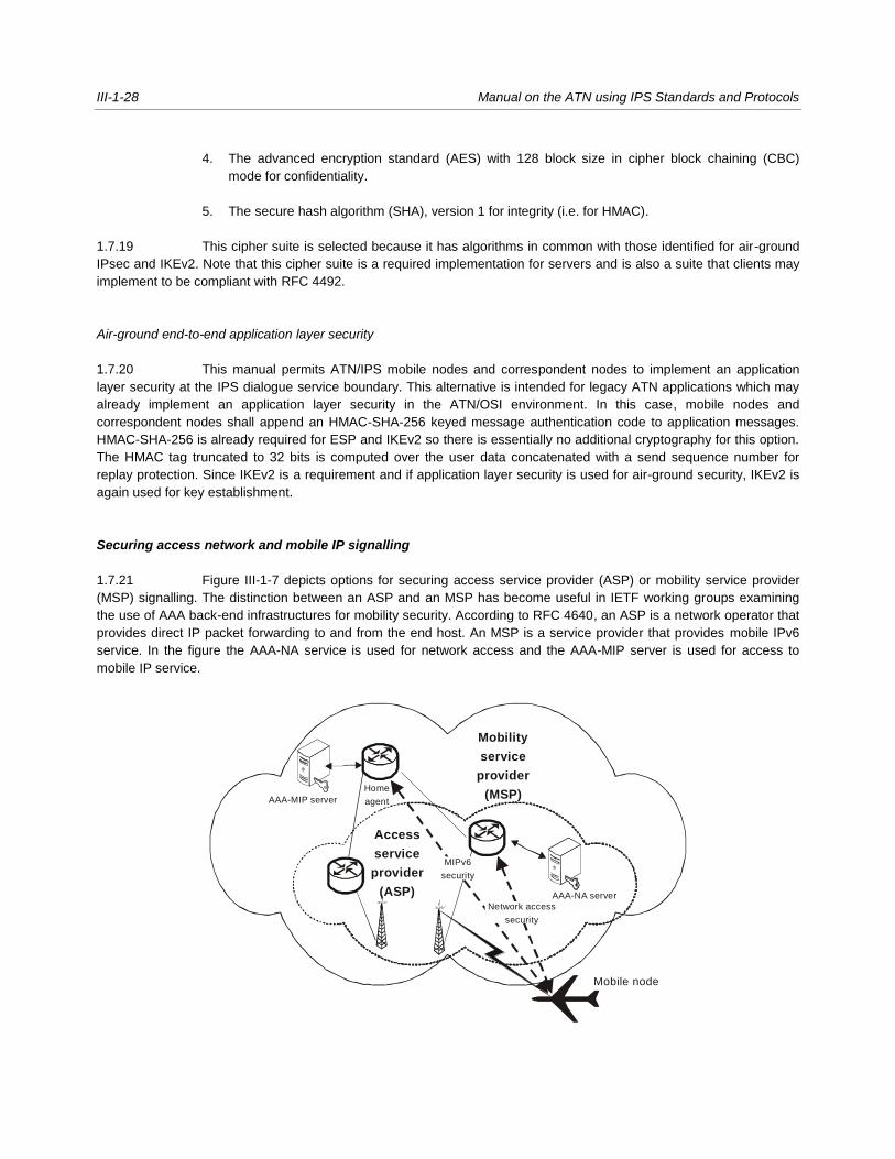
III-1-28 Manual on the ATN using IPS Standards and Protocols
4. The advanced encryption standard (AES) with 128 block size in cipher block chaining (CBC)
mode for confidentiality.
5. The secure hash algorithm (SHA), version 1 for integrity (i.e. for HMAC).
1.7.19 This cipher suite is selected because it has algorithms in common with those identified for air-ground
IPsec and IKEv2. Note that this cipher suite is a required implementation for servers and is also a suite that clients may
implement to be compliant with RFC 4492.
Air-ground end-to-end application layer security
1.7.20 This manual permits ATN/IPS mobile nodes and correspondent nodes to implement an application
layer security at the IPS dialogue service boundary. This alternative is intended for legacy ATN applications which may
already implement an application layer security in the ATN/OSI environment. In this case, mobile nodes and
correspondent nodes shall append an HMAC-SHA-256 keyed message authentication code to application messages.
HMAC-SHA-256 is already required for ESP and IKEv2 so there is essentially no additional cryptography for this option.
The HMAC tag truncated to 32 bits is computed over the user data concatenated with a send sequence number for
replay protection. Since IKEv2 is a requirement and if application layer security is used for air-ground security, IKEv2 is
again used for key establishment.
Securing access network and mobile IP signalling
1.7.21 Figure III-1-7 depicts options for securing access service provider (ASP) or mobility service provider
(MSP) signalling. The distinction between an ASP and an MSP has become useful in IETF working groups examining
the use of AAA back-end infrastructures for mobility security. According to RFC 4640, an ASP is a network operator that
provides direct IP packet forwarding to and from the end host. An MSP is a service provider that provides mobile IPv6
service. In the figure the AAA-NA service is used for network access and the AAA-MIP server is used for access to
mobile IP service.
Mobile node
AAA-MIP server
AAA-NA server
Network access
security
Mobility
service
provider
(MSP)
Access
service
provider
(ASP)
MIPv6
security
Home
agent

Part III — Guidance Material
Chapter 1 — Introduction III-1-29
Figure III-1-7. ASP or MSP security
Securing mobile IP signalling
1.7.22 Consistent with RFC 3775, this manual requires that IPsec be used specifically for protection of mobile
IP signalling in conformance to RFC 4877. RFC 4877 is an update of RFC 3776 and describes how IKEv2 is to be used
for automated key management. RFC 4877 in particular describes how IKEv2 with EAP as the authentication method
may be used. When extensible authentication is used in IKEv2 there is an additional exchange after the IKE_SA_INIT
and IKE_SA_AUTH exchanges. In this case, the MN will not include an authentication payload in the IKE_SA_AUTH
exchange but rather will include an EAP payload in the next message. The HA then interacts with the AAA-MIP server to
complete the authentication exchange and, if successful, completes the IKEv2 exchange.
Air-ground access network security
1.7.23 Mobile nodes shall implement the security provisions of the access network. The security provisions of
an access network are those associated with access control to the network itself and are typically implemented using an
AAA infrastructure.
1.7.24 The IETF mobility working groups and other standards development organizations have recognized
that, although mobile IPv6 and proxy mobile IPv6 were originally designed without integration with an AAA infrastructure,
it may be more efficient to authenticate users using credentials stored at the AAA server. Furthermore, use of an AAA
infrastructure may facilitate other bootstrapping functions such as dynamic configuration of other parameters (i.e. the
home address and home agent address) in order to accomplish mobility registration. EAP between the MN and
authenticator may operate over the access network link level protocol or in conjunction with IKEv2 as described for
securing mobile IP signalling. EAP between the authenticator and AAA server operates over RADIUS (RFC 2865) or
DIAMETER (RFC 3588).
Public key infrastructure profile and certificate policy
1.7.25 this manual requires that ATN/IPS nodes use the Internet X.509 public key infrastructure certificate
and certificate revocation list (CRL) profile as specified in RFC 5280 and the Internet X.509 public key infrastructure
certificate policy and certificate practices framework as specified in RFC 3647. This manual notes that the Air Transport
Association (ATA) Digital Security Working Group (DSWG) has developed a certificate policy (ATA Specification 42) for
use in the aviation community. ATA Specification 42 includes certificate and CRL profiles that are suitable for
aeronautical applications. These profiles provide greater specificity than, but do not conflict with, RFC 5280. The ATA
Specification 42 profiles are interoperable with an aerospace industry PKI bridge. Interoperability with an operational
aerospace and defence PKI bridge will provide the opportunity to leverage existing infrastructure rather than develop an
infrastructure unique to the ATN/IPS and will more readily achieve interoperability and policy uniformity in a multi-
national, multi-organizational aerospace and defence environment.
General guidance for implementation of security
1.7.26 Many government agencies have developed additional guidance and profiles for implementing
security. In the United States the NIST 800 series of recommendations is an example of general security implementation
guidance covering a broad range of topics.
1.7.27 In the IETF there have been many Internet drafts dealing with security. Two informational RFCs of
particular interest are RFC 4942 and RFC 4864. RFC 4942 gives an overview of security issues associated with IPv6.
The issues are grouped into three general categories: issues due to the IPv6 protocol itself; issues due to transition
mechanisms; and issues due to IPv6 deployment. RFC 4864 notes that network address translation (NAT) is not

III-1-30 Manual on the ATN using IPS Standards and Protocols
required in IPv6 and describes how local network protection (LNP) mechanisms can provide the security benefits
associated with NAT. In particular, RFC 4864 describes how the IPv6 tools for privacy addresses, unique local
addresses, DHCPv6 prefix delegation, and untraceable IPv6 addresses may be used to provide the perceived security
benefits of NAT, including the following: gateway between the Internet and an internal network; simple security (derived
from stateful packet inspection); user/application tracking; privacy and topology hiding; independent control of
addressing in a private network; global address pool conservation; and multihoming and renumbering. RFC 4864
describes the additional benefits of native IPv6 and universal unique addressing, including the following: universal any-
to-any connectivity, auto-configuration, native multicast services, increased security protection, mobility, and merging
networks.
1.8 VOICE-OVER INTERNET PROTOCOL (VoIP)
1.8.1 The key advantages associated with the use of a packet network for the transmission of digitized voice
are:
— bandwidth allocation efficiency;
— the ability to use modern voice compression methods;
— associate economics with shared network use;
— reduced costs;
— enhanced reliability of packet networks; and
— the ability to use multiple logical connections over a single physical circuit.
1.8.2. EUROCAE publishes a series of documents on VoIP for ATM which may be used as additional specification
material. These documents are numbered ED 136, ED 137, ED 138 and consist of:
- ED-136 – VoIP ATM System Operational and Technical requreiements, edition, February ####
- ED-137 – Interoperability Standards for VoIP ATM Components with the following volumes;
o VOL1 – Radio, edition January 2012
o ED137/2B - VOL 2 – Telephone, edition January 2012
o ED137/3B - VOL 3 – European Legacy Telephone Interworking, edition January 2012
o ED137/4B - VOL 4 – Recording, edition January 2012
o ED137/5B - VOL 5 – Supervision, edition January 2012
- ED-138 - Network Requirements and Performances for VoIP ATM Systems with the following
parts:
o ED-138 Part1 – Network Specification, edition February 2009

Part III — Guidance Material
Chapter 1 — Introduction III-1-31
o ED-138 Part 2 – Network Design Guideline, edition February 2009
They are available on the EUROCAE website at; http://www.eurocae.net/
1.9 IPS IMPLEMENTATIONS
Online data interchange (OLDI)
1.9.1 Online data interchange (OLDI) combined with the flight message transfer protocol (FMTP) is a means
to enable AIDC operational requirements for the coordination and transfer of aircraft between adjacent air traffic control
units. The relationship between AIDC and OLDI messages is described in the Manual of Air Traffic Services Data Link
Applications (Doc 9694), Part VI, Chapter 1, Appendix. The OLDI specification does not mandate the implementation of
OLDI messages but specifies the requirements that need to be met when implementing such facilities. If OLDI
messages are implemented as the result of regulatory provisions, or based on bilateral agreement between air traffic
control units, then the requirements outlined as mandatory in this specification for those messages become mandatory
for implementation. This is required in order to meet the purposes of the messages and to ensure interoperability
between systems. The coordination procedure requires that systems identify whether transfers are in accordance with
the Letters of Agreements (LoAs). The process which checks such compliance is referred to in the OLDI specification as
“the filter”. The database used for the filter may include the following:

III-1-32 Manual on the ATN using IPS Standards and Protocols
— agreed coordination points;
— eligible (or ineligible) flight levels which may also be associated with the coordination points;
— aerodromes of departure;
— destinations;
— agreed direct routes;
— time and/or distance limits prior to the COP, after which any coordination message is considered
non-standard; and
— any other conditions, as bilaterally agreed.
1.9.2 All items in this list may be combined to define more complex conditions. The format of the messages
(see ICAO Procedures for Air Navigation Services ─ Air Traffic Management (PANS-ATM) (Doc 4444) or
EUROCONTROL Standard Document for ATS Data Exchange Presentation (ADEXP) to be transmitted and received
has to be agreed bilaterally. The address of the ATS units providing the services has to be agreed bilaterally and has to
be different from the addresses of the other units to which the ATS units are already connected or planned to be
connected. The ATS unit addresses are part of the OLDI message.
Flight message transfer protocol (FMTP)
1.9.3 The flight message transfer protocol (FMTP) is a communications stack based on TCP/IPv6 to support
the transmission of OLDI messages. FMTP is a state machine that handles connection establishment and session
management. Each FMTP system requires an identification value that is to be exchanged during connection
establishment. The identification values have to be agreed bilaterally and must be different from the values of the other
units to which the ATS units are already connected or planned to be connected.
1.9.4 The FMTP specification assumes the transfer of ASCII characters, but implementations of the protocol
may extend this support to other character sets or binary transfers. Further guidance material on FMTP is available from
EUROCONTROL at the following website:
http://www.eurocontrol.int/communications/public/standard_page/com_network.html
Testing OLDI/FMTP
1.9.5 EUROCONTROL has developed a test tool named EUROCONTROL inter centre test tool (ETIC) to
validate OLDI/FMTP implementations and build test scenarios. The tool can be made available upon request at:
AMHS

Part III — Guidance Material
Chapter 1 — Introduction III-1-33
1.9.6 AMHS has already achieved operational status over TCP/IP in the European and North American
regions. It is to be noted that the European deployments make use of IPv6 for network interconnections in line with Part
II of this document.
______________________


III-APP-1
APPENDIX to Part III
REFERENCE DOCUMENTS
IETF STANDARDS AND PROTOCOLS
The following documents are available publicly at http://www.ietf.org and form part of this manual to the extent specified
herein. In the event of conflict between the documents referenced herein and the contents of this manual, the provisions
of this manual shall take precedence.
Request for comments (RFCs)
netlmm-mn-ar-if Network-based Localized Mobility Management Interface between Mobile Node and Mobility Access
Gateway, May 2007
RFC 768 User Datagram Protocol, August 1980
RFC 793 Transmission Control Protocol (TCP), September 1981
RFC 1006 ISO Transport Service on top of TCP, May 1987
RFC 1122 Requirements for Internet Hosts – Communication Layers
RFC 1123 Requirements for Internet Hosts – Application and Support
RFC 1323 TCP Extensions for High Performance, May 1992
RFC 1981 Path Maximum Transmission Unit (MTU) Discovery for IP Version 6, August 1996
RFC 2126 ISO Transport Service on top of TCP, March 1997
RFC 2385 Protection of BGP Sessions via the TCP MD5 Signature Option
RFC 2460 Internet Protocol, Version 6 (IPv6) Specification, December 1998
RFC 2474 Definition of Differentiated Services Field (DS Field) in the IPv4 and IPv6 Headers, December 1998
RFC 2475 An Architecture for Differentiated Service
RFC 2488 Enhancing TCP over Satellite Channels, January 1999
RFC 2597 Assured Forwarding PHB Group
RFC 2858 Multiprotocol Extensions for Border Gateway Protocol (BGP-4), June 2000
RFC 3095 Robust Header Compression (ROHC): Framework and Four Profiles; RTP, UDP, ESP, and
Uncompressed
RFC 3241 Robust Header Compression (ROHC) over PPP
RFC 3246 An Expedited Forwarding PHB (Per-Hop Behaviour)
RFC 3602 The AES-CBC Cipher Algorithm and Its Use with IPsec
RFC 3647 Internet X.509 Public Key Infrastructure Certificate Policy and Certification Practices Framework
RFC 3775 Mobility Support in IPv6, June 2004
RFC 3963 Network Mobility (NEMO) Basic Support Protocol
RFC 4106 The use of Galois/Counter Mode (GCM) in IPsec Encapsulating Security Payload (ESP)
RFC 4213 Basic Transition Mechanisms for IPv6 Hosts and Routers
RFC 4271 A Border Gateway Protocol 4 (BGP-4), January 2006
RFC 4291 IP Version 6 Addressing Architecture, February 2006
RFC 4301 Security Architecture for the Internet Protocol, December, 2005
RFC 4302 Internet Protocol (IP) Authentication Header, December 2005
RFC 4303 IP Encapsulating Security Payload (ESP), December 2005
RFC 4306 Internet Key Exchange (IKEv2) Protocol, December 2005
RFC 4307 Cryptographic Algorithms for Use in the Internet Key Exchange Version 2 (IKEv2), December 2005
RFC 4443 Internet Control Message Protocol (ICMPv6) for the Internet Protocol Version 6 (IPv6) Specification,
March 2006

III-APP-2 Manual on the ATN using IPS Standards and Protocols
RFC 4492 Elliptic Curve Cryptography (ECC) Cipher Suites for Transport Layer Security (TLS), May 2006
RFC 4555 IKEv2 Mobility and Multihoming Protocol (MOBIKE), June 2006
RFC 4753 Encryption Control Protocol (ECP) Groups for IKE and IKEv2
RFC 4754 IKE and IKEv2 Authentication Using the Elliptic Curve Digital Signature Algorithm (ECDSA)
RFC 4830 Problem Statement for Network-Based Localized Mobility Management (NETLMM), April 2007
RFC 4831 Goals for Network-Based Localized Mobility Management (NETLMM), April 2007
RFC 4835 Cryptographic Algorithm Implementation Requirements for Encapsulating Security Payload (ESP) and
Authentication Header (AH) ,April 2007
RFC 4843 An IPv6 Prefix for Overlay Routable Cryptographic Hash Identifiers (ORCHID)
RFC 4868 Using HMAC-SHA-256, HMAC-SHA-384 and HMAC-SHA-512 with IPsec
RFC 4877 Mobile IPv6 Operation with IKEv2 and the Revised IPsec Architecture
RFC 4996 Robust Header Compression (ROHC): A Profile for TCP/IP (ROHC-TP)
RFC 5246 The Transport Layer Security (TSL) Protocol Version 1.2
RFC 5280 Internet X.509 Public Key Infrastructure Certificate and Certificate Revocation List (CRL) Profile
RELEVANT ICAO PUBLICATIONS
In the event of a conflict between this manual and the provisions in Annex 10, the provisions of Annex 10 shall take
precedence.
Annex 2 — Rules of the Air
Annex 3 — Meteorological Service for International Air Navigation
Annex 10 — Aeronautical Telecommunications, Volume III — Communication Systems, Part I — Digital Data
Communication Systems
Annex 11 — Air Traffic Services
Procedures for Air Navigation Services — Air Traffic Management (PANS-ATM) (Doc 4444)
ICAO Manuals
Manual of Air Traffic Services Data Link Applications (Doc 9694)
Manual of Technical Provisions for the Aeronautical Telecommunication Network (ATN) (Doc 9705)
Comprehensive Aeronautical Telecommunication Network (ATN) Manual (Doc 9739)
Manual on Detailed Technical Specifications for the Aeronautical Telecommunication Network (ATN) using ISO/OSI
Standards and Protocols (Doc 9880) (in preparation)
ICAO EUR AMHS Manual, EUR DOC 020, Version 9.0
http://www.paris.icao.int/documents_open/files.php?subcategory_id=74
IP Infrastructure Test Guidelines for European AMHS, EUR DOC 027, Version 1.0
http://www.paris.icao.int/documents_open/files.php?subcategory_id=158

Part III — Guidance Material
Appendix — Reference documents III-APP 3
EUROCAE Documents
The following documents are available at http://www.eurocae.net and form part of this manual to the extent specified
herein. In the event of conflict between the documents referenced herein and the contents of this manual, the provisions
of this manual shall take precedence.
ED-136 – VoIP ATM System Operational and Technical requreiements, edition, February 2009
ED-137 – Interoperability Standards for VoIP ATM Components with the following volumes;
o VOL1 – Radio, edition January 2012
o ED137/2B - VOL 2 – Telephone, edition January 2012
o ED137/3B - VOL 3 – European Legacy Telephone Interworking, edition January 2012
o ED137/4B - VOL 4 – Recording, edition January 2012
o ED137/5B - VOL 5 – Supervision, edition January 2012
ED-138 - Network Requirements and Performances for VoIP ATM Systems with the following parts:
o ED-138 Part1 – Network Specification, edition February 2009
o ED-138 Part 2 – Network Design Guideline, edition February 2009
EUROCONTROL DOCUMENTS
The following documents are available publicly at http://www.eurocontrol.int/ses and form part of this manual to the
extent specified herein. In the event of conflict between the documents referenced herein and the contents of this
manual, the provisions of this manual shall take precedence.
EUROCONTROL-SPEC-0100-EUROCONTROL Specification of Interoperability and Performance Requirements for the
Flight Message Transfer Protocol (FMTP), Edition 2.0, June 2007
EUROCONTROL-SPEC-0106-EUROCONTROL Specification for On-Line Data Interchange (OLDI), Edition 4.1,
January 2008
“Coordination Guidelines for PENS-Interconnected COM Centres”
available on AMC (ATS Messaging Management Centre, see http://www.eurocontrol.int/amc/ ), under
“Helpdesk Functions / Download Support Information”.
— END —