pulsed alternators - university of texas at austin · pdf filesteam turbine. brushed...
TRANSCRIPT
PULSED ALTERNATORS
Scott Pish, Jon Hahne, Angelo Gattozzi
Center for Electromechanics
The University of Texas at Austin
8/14/17

Tutorial Objectives
• Provide a detailed understanding
of rotating-machine-based pulsed
power systems
• Review the maturation of pulsed
alternator technology
• Introduce technologies enabling
increased power and energy
density
• Discuss shipboard integration
Iron-Core Compensated Pulsed Alternator
Twin
Round-Bore
Railguns
SSFTP Pulsed Alternator
Railgun &
Resistive
Load

Presenters
Mr. Jon Hahne
• Senior Engineering Scientist, Program Manager
• Development, design, manufacture, and test of prototype rotating
electrical machines.
• B.S., Mechanical Engineering 1986
Dr. Angelo Gattozzi
• Research Associate, IEEE Senior Member
• Electric power system modeling and simulation, smart-grid/micro-grid
systems, Navy power systems, high-speed motors/generators
• Ph.D., Electrical Engineering and Applied Physics 1978
Mr. Scott Pish
• Research Engineer, Program Manager
• Manufacture & test of prototype rotating machines,
• Design, analysis, & fabrication of composite structures
• B.S. Mechanical Engineering 1996

TECHNOLOGY
BACKGROUND

How We Got Here
• Chinese technical literature credits the University of Texas
researchers with the invention of the modern pulsed alternator
• But pulsed alternators evolved, rather than were invented,
through UT’s efforts to make rotating machines more power
and energy dense (Motors, Generators, Energy storage)
• Increasing power and energy density is a long term research
objective of UT and requires advances in
• Rotating machine design
• Materials
• Power electronics
• Advanced controls
All areas of traditional and growing expertise at UT’s CEM
Power and Energy Density
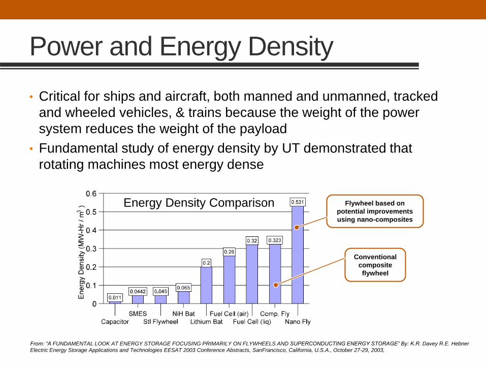
• Critical for ships and aircraft, both manned and unmanned, tracked
and wheeled vehicles, & trains because the weight of the power
system reduces the weight of the payload
• Fundamental study of energy density by UT demonstrated that
rotating machines most energy dense
Flywheel based on
potential improvements
using nano-composites
Conventional
composite
flywheel
From: “A FUNDAMENTAL LOOK AT ENERGY STORAGE FOCUSING PRIMARILY ON FLYWHEELS AND SUPERCONDUCTING ENERGY STORAGE” By: K.R. Davey R.E. Hebner
Electric Energy Storage Applications and Technologies EESAT 2003 Conference Abstracts, SanFrancisco, California, U.S.A., October 27-29, 2003,
Energy Density Comparison

Powering EM guns
• EM guns have been successfully
powered by
• Rotating machines
• Batteries
• Capacitors
• Inductors
• The Army and Marines both developed
EM guns for wheeled vehicles
• Both were based on pulsed alternators as they provided the greatest
power and energy density
• The Navy chose a less power dense solution for their initial efforts
• Likely that the Army pushed the power density beyond the Navy’s
threshold

CENTER FOR
ELECTROMECHANICS

UT-Austin Center for Electromechanics
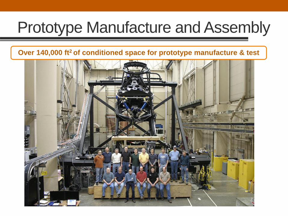
Prototype Manufacture and Assembly
Over 140,000 ft2 of conditioned space for prototype manufacture & test
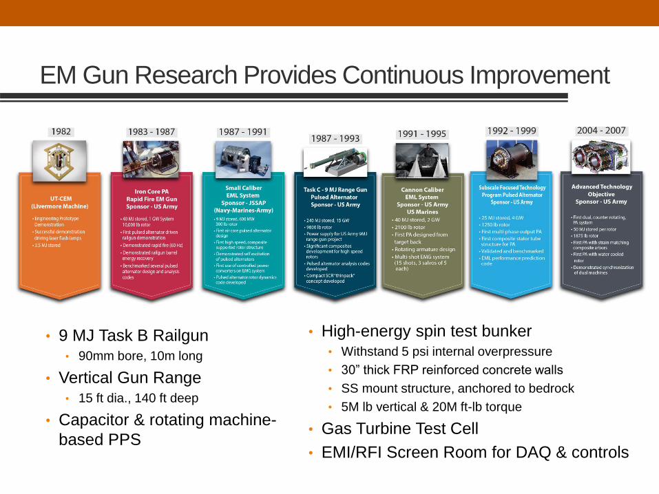
EM Gun Research Provides Continuous Improvement
• 9 MJ Task B Railgun • 90mm bore, 10m long
• Vertical Gun Range • 15 ft dia., 140 ft deep
• Capacitor & rotating machine-
based PPS
• High-energy spin test bunker• Withstand 5 psi internal overpressure
• 30” thick FRP reinforced concrete walls
• SS mount structure, anchored to bedrock
• 5M lb vertical & 20M ft-lb torque
• Gas Turbine Test Cell
• EMI/RFI Screen Room for DAQ & controls

Design and Testing of Power Systems
3MW, 15 krpm4MW, 480MJ
2MW, 15 krpm
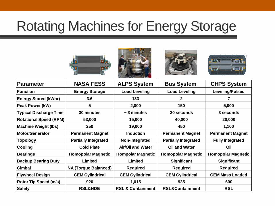
Rotating Machines for Energy Storage
Parameter NASA FESS ALPS System Bus System CHPS System
Function Energy Storage Load Leveling Load Leveling Leveling/Pulsed
Energy Stored (kWhr) 3.6 133 2 7
Peak Power (kW) 5 2,000 150 5,000
Typical Discharge Time 30 minutes ~ 3 minutes 30 seconds 3 seconds
Rotational Speed (RPM) 53,000 15,000 40,000 20,000
Machine Weight (lbs) 250 19,000 450 1,100
Motor/Generator Permanent Magnet Induction Permanent Magnet Permanent Magnet
Topology Partially Integrated Non-Integrated Partially Integrated Fully Integrated
Cooling Cold Plate Air/Oil and Water Oil and Water Oil
Bearings Homopolar Magnetic Hompolar Magnetic Homopolar Magnetic Homopolar Magnetic
Backup Bearing Duty Limited Limited Significant Significant
Gimbal NA (Torque Balanced) Required Required Required
Flywheel Design CEM Cylindrical CEM Cylindrical CEM Cylindrical CEM Mass Loaded
Rotor Tip Speed (m/s) 920 1,015 935 600
Safety RSL&NDE RSL & Containment RSL&Containment RSL

Pulsed Power Testing
Capacitor-based 12 MJ Pulse Forming Network
(PFN)
Railgun4m long, 54mm
square-bore
Projectile Soft-Catch system

Microgrid Facility
Supports Navy and other research
with new HIL & CHIL capability

Providing solutions
Prototype Navy EMALS generator developed at UT-CEM successfully transitioned
to industrial partners for deployment
• Developed system simulation models
• Design, built, & tested the prototype generator
• 20% lower mass & volume than commercially available power supplies

PULSED ALTERNATOR
TECHNOLOGY BASICS OVERVIEW
Jon Hahne
Center for Electromechanics
The University of Texas at Austin
8/14/2017
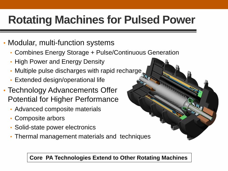
Rotating Machines for Pulsed Power
• Modular, multi-function systems
• Combines Energy Storage + Pulse/Continuous Generation
• High Power and Energy Density
• Multiple pulse discharges with rapid recharge
• Extended design/operational life
• Technology Advancements Offer
Potential for Higher Performance
• Advanced composite materials
• Composite arbors
• Solid-state power electronics
• Thermal management materials and techniques
Core PA Technologies Extend to Other Rotating Machines

Flywheel Topologies
• ee
Non-Integrated Topology
• Larger than other topologies, but
may have most simple assembly
• Maximum use of conventional M/G
systems and technology
• Flexible / adaptive design
• Power generation outside of vacuum
• Requires shaft seal and coupling
Partially-Integrated Topology
• Smaller and more efficient than non-
integrated
• Good use of available M/G technology,
but integration required
• Good design adaptability
• Favors use of PM generator
• Heat generation on rotor requires
careful engineering
Fully-Integrated Topology
• Most compact system
• Special purpose flywheel system
• Favors use of PM generator
• Heat generation on rotor requires
special engineering
• Rotating magnets at large radius

Non-Integrated Topology
• Federal Railroad Authority –
Advanced Locomotive
Propulsion System
• 480 MJ, 15 krpm flywheel
• 3 MW motor/generator
• Flex drive coupling
interconnect
UT-CEM

Partially Integrated Topology
• Transit Bus flywheel battery
power system
• 7 MJ, 40 krpm flywheel
• 150 KW motor/generator
• Flywheel & Electrical section
• On common shaft
• Inside vacuum enclosure
UT-CEM

Fully Integrated Topology
• US Army Subscale
Focused Technology
Program pulsed alternator
• 22 MJ, 12 krpm flywheel
• Wound field coil
• 2 GW peak delivered
power
• Energy storage in power
generation section
UT-CEM

PULSED ALTERNATORS

Pulsed Alternators Are:
• A unique class of rotating electrical machines
• Specifically designed for driving transient loads
• A well-characterized and demonstrated technology
• “Conventional” electrical devices with “Non-conventional”
challenges
• Mechanical design
• Thermal design
• Assembly processes
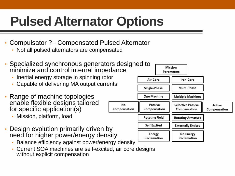
Pulsed Alternator Options
• Compulsator ?– Compensated Pulsed Alternator• Not all pulsed alternators are compensated
• Specialized synchronous generators designed to minimize and control internal impedance • Inertial energy storage in spinning rotor
• Capable of delivering MA output currents
• Range of machine topologies enable flexible designs tailored for specific application(s)• Mission, platform, load
• Design evolution primarily driven by need for higher power/energy density• Balance efficiency against power/energy density
• Current SOA machines are self-excited, air core designs without explicit compensation

Armature Compensation
• Compensation: Methods used to control machine internal
impedance
• More critical for single phase, single-pulse machines
• Determines output pulse characteristics
• Three basic approaches to compensation:
• Active – compensation provided by a secondary armature winding in
series with the primary winding. This provides a sharp “peaky” pulse
• Passive – compensation provided by continuous conductive shield
between the field and armature windings; impedance independent of
rotor position providing roughly sinusoidal output pulse
• Selective Passive – compensation provided by shorted compensating
windings; varying impedance with rotor position provides pulse shaping
Compensation Increases Complexity and Technical Risk
Multi-phase Air-Core Machines do not Require Explicit Compensation

Synchronous Generator Operation
• Voltage induced in each stator winding by passage of the
rotating magnetic field created by the field winding
P As x B x L x D2 x w
As – stator line current densityB – air gap flux densityL – lengthD – diameterw– angular velocity

Power to Load
Voltage Regulator
(Field Current
Control)
Mechanical
Torque
Brushless Synchronous Generator
• DC field excitation provided by exciter and rotating rectifier
• Voltage regulator modulates exciter field current which in turn controls generator field current and thus the output voltage
Exciter Field
Excitation
Excitation
Power
Input
Power Input
Diesel Genset
Gas Turbine
Motor
Steam Turbine
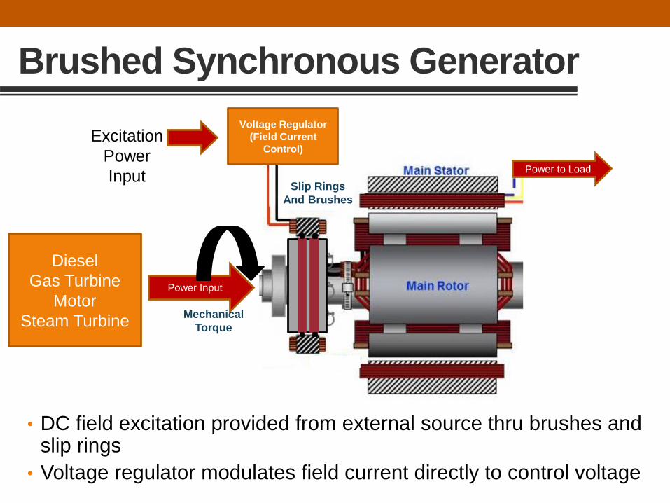
Brushed Synchronous Generator
• DC field excitation provided from external source thru brushes and slip rings
• Voltage regulator modulates field current directly to control voltage
Excitation
Power
Input
Diesel
Gas Turbine
Motor
Steam Turbine
Power to Load
Voltage Regulator
(Field Current
Control)
Mechanical
Torque
Slip Rings
And Brushes
Power Input
Power To FieldVoltage Regulator
(Field Current
Control)
Mechanical
Torque
Slip Rings
And Brushes
Main Generator OutputExciter
Seed
Current
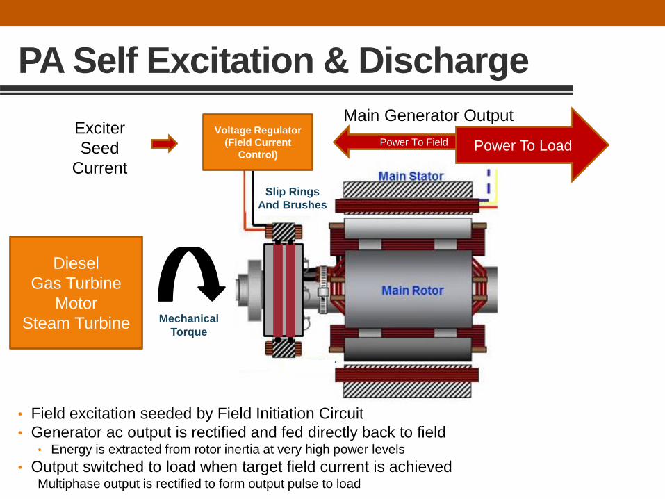
PA Self Excitation & Discharge
• Field excitation seeded by Field Initiation Circuit
• Generator ac output is rectified and fed directly back to field• Energy is extracted from rotor inertia at very high power levels
• Output switched to load when target field current is achievedMultiphase output is rectified to form output pulse to load
Power To Load
Diesel
Gas Turbine
Motor
Steam Turbine

Pulsed Alternator System

Hardware Example --Army Focused Technology System
• Self Excited
• Air Core
• 3 phase output
• Diode
converters
• Explosives
safety switching
3 Phase Alternator
(22 MJ stored)
Field Int. Mod.
3 phase
Field converter (1/2 of FW bridge)
EM Launcher
3 phase
Field converter (1/2 of FW bridge)
Gun converter (half wave)
Fixed resist. load
Explosive switches
Explosive switch

Discharge Sequence & Timeline
The electrical angle of the output is acquired with a cycle portion
encoder and from here excitation of the generator and the discharge
into to railgun along with energy reclamation is accomplished
• Initial Conditions:
• Rotor at Speed
• Field Initiation
Capacitor
Charged

Example PA Output
• 15,000 rpm discharge simulation
• 4 phase output
• 4 m launcher
• Pulses after exit are energy reclamation
• “Flatter” pulse shape is desired
--------------------------------------
• Higher frequency switching improves pulse shape• Faster machine speeds
• Higher pole count
• “Phase shifting” multiple machine outputs smoothespulse shape
1.6
1.4
1.2
1.0
0.8
0.6
0.4
0.2
0.0
Curr
ent
(MA
)
2422201816
Time (msec)
20
18
16
14
12
10
8
6
4
2
0
Dis
pla
cem
ent (m
)
ILP Exits GunAcceleration Ratio : 63%
Gun Curr
ILP Arm Curr
Muzz Curr
Phase Arm1
Phase Arm2
Phase Arm3
Phase Arm4
ILP disp

Applying PA Technology to Real Hardware
• Six generations of
pulsed alternator
development history
• Each generation
designed for specific
system requirements
• Evolution of
technology
development
• Steady progression in
energy and power
density
ATO

PA TECHNOLOGY DEVELOPMENT
Scott Pish
Center for Electromechanics
The University of Texas at Austin
8/14/17

Pulsed Alternator Development at UT
Pulsed Alternator Research
• CEM invents CPA (1978)
• Livermore Machine Prototype
• Iron Core CPA
• Small Caliber EML System
• Subscale FTP PA System
• Army ATO PA System
Related Research:
• ESRDC (2003-present)
• EMALS generator demo (2003)
• EM Gun Soft Catch demo (2014)
• CHPS development spin test (2015)
• EM Gun Microgrid Integration (2016)

• Every contractor defined technical requirement was demonstrated
• 40 MJ, 1 GW iron-core compulsator
• Demonstrated “firsts”:
• Fully operational multi shot system with auxiliaries
• First demonstration rail gun energy recovery
• First use of solid-state thyristor switch in PPS
• Benchmarked rail gun system and component design & analysis codes
• Developed resin-transfer VPI system (still in use today)
• Fully demonstrated system performance
• Outcomes:
• Developed higher fidelity design and analysis tools that previously did not exist
• Iron core too massive for tactical application and without adequate growth potential
Iron Core CPA EML System

• Order of magnitude increase in energy/power density
• Demonstrated “firsts”:
• First self-excited air-core CPA
• First demonstration of self-excitation in PPS
• First demonstration of muzzle shunt with a passive muzzle switch to significantly reduce muzzle arc
• First use of ceramic (rolling element) bearings and fluid dampeners in PPS
• Validated self-excited, air-core compulsator performance codes
• Demonstrated single shot predicted performance from 21,500 rpm
• Complex non-conducting shaft led to rotor dynamics issue
• Rotor vibration issues limited peak speed
• Full electrical and shot energy performance was demonstrated
• Outcomes:
• Identified need for high fidelity rotor dynamic model.
• Stationary two-pole field limits growth in energy and power density.
Small Caliber CPA EML System
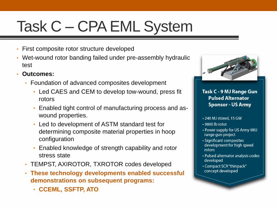
Task C – CPA EML System
• First composite rotor structure developed
• Wet-wound rotor banding failed under pre-assembly hydraulic
test
• Outcomes:
• Foundation of advanced composites development
• Led CAES and CEM to develop tow-wound, press fit
rotors
• Enabled tight control of manufacturing process and as-
wound properties.
• Led to development of ASTM standard test for
determining composite material properties in hoop
configuration
• Enabled knowledge of strength capability and rotor
stress state
• TEMPST, AXIROTOR, TXROTOR codes developed
• These technology developments enabled successful
demonstrations on subsequent programs:
• CCEML, SSFTP, ATO
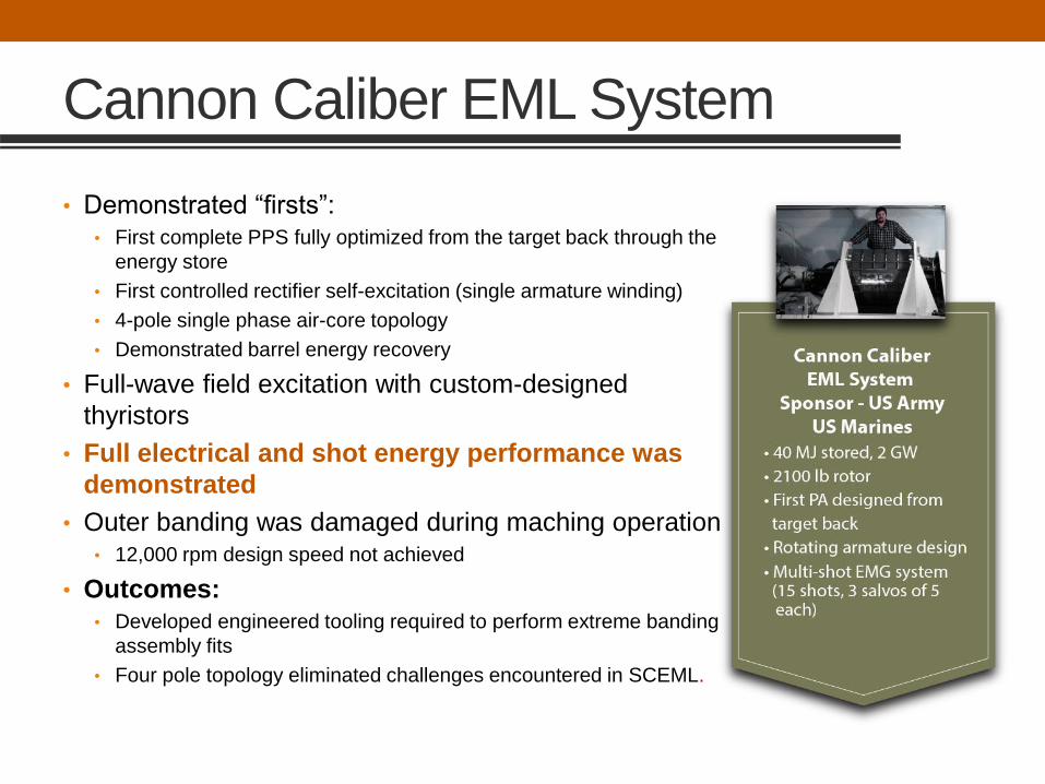
Cannon Caliber EML System
• Demonstrated “firsts”:• First complete PPS fully optimized from the target back through the
energy store
• First controlled rectifier self-excitation (single armature winding)
• 4-pole single phase air-core topology
• Demonstrated barrel energy recovery
• Full-wave field excitation with custom-designed
thyristors
• Full electrical and shot energy performance was
demonstrated
• Outer banding was damaged during maching operation• 12,000 rpm design speed not achieved
• Outcomes:• Developed engineered tooling required to perform extreme banding
assembly fits
• Four pole topology eliminated challenges encountered in SCEML.

Subscale FTP EML System
• Demonstrated “firsts”:
• First rotating field, multi-phase, air-core PA (no compensation)
• First demonstration of field energy recovery
• First composite stator and armature structure
• First use of LSS thyristor device technology developed for EML
application
• Development of very high-speed, high accuracy encoder for
measuring rotor position
• Originally conceived as a rotor spin test, after the start of
manufacturing two requirements were added:
• Operation of machine electrically
• Very accurate a-priori performance prediction
• Rotor field winding insulation failure prompted rotor redesign.
• Met every program goal and objective including matching
a-priori predicted performance simulations
• Outcomes:
• Led to improvements in high strain-capable insulation systems
• Led to designing all composite rotor rim structure on ATO program.
• SSFTP rotor titanium shell and end bells limited efficiency and
power and energy density.
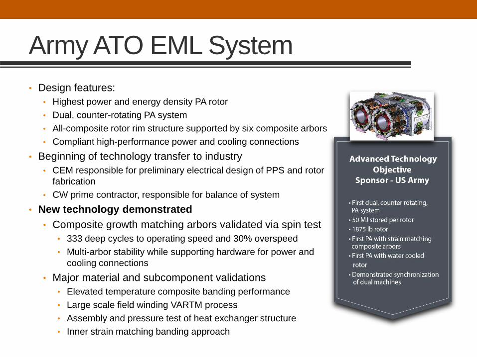
Army ATO EML System
• Design features:
• Highest power and energy density PA rotor
• Dual, counter-rotating PA system
• All-composite rotor rim structure supported by six composite arbors
• Compliant high-performance power and cooling connections
• Beginning of technology transfer to industry
• CEM responsible for preliminary electrical design of PPS and rotor
fabrication
• CW prime contractor, responsible for balance of system
• New technology demonstrated
• Composite growth matching arbors validated via spin test
• 333 deep cycles to operating speed and 30% overspeed
• Multi-arbor stability while supporting hardware for power and
cooling connections
• Major material and subcomponent validations
• Elevated temperature composite banding performance
• Large scale field winding VARTM process
• Assembly and pressure test of heat exchanger structure
• Inner strain matching banding approach
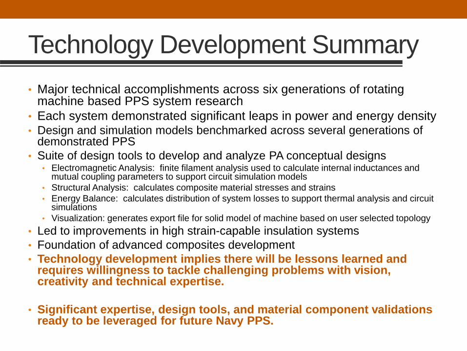
Technology Development Summary
• Major technical accomplishments across six generations of rotating machine based PPS system research
• Each system demonstrated significant leaps in power and energy density• Design and simulation models benchmarked across several generations of
demonstrated PPS
• Suite of design tools to develop and analyze PA conceptual designs• Electromagnetic Analysis: finite filament analysis used to calculate internal inductances and
mutual coupling parameters to support circuit simulation models
• Structural Analysis: calculates composite material stresses and strains
• Energy Balance: calculates distribution of system losses to support thermal analysis and circuit simulations
• Visualization: generates export file for solid model of machine based on user selected topology
• Led to improvements in high strain-capable insulation systems
• Foundation of advanced composites development
• Technology development implies there will be lessons learned and requires willingness to tackle challenging problems with vision, creativity and technical expertise.
• Significant expertise, design tools, and material component validations ready to be leveraged for future Navy PPS.

CRITICAL TECHNOLOGIES
Scott Pish
Center for Electromechanics
The University of Texas at Austin
8/14/17

Critical Technologies
• Alternators are well-understood rotating electrical machines.
• The Pulsed Alternator is a special class of alternator
designed for high power and energy density.
• To achieve the highest power and energy densities, the PA
must be optimized in several ways.
• This requires specialized capabilities and knowledge
including:
• Refined performance simulations and modelling capabilities
• High-fidelity thermal models and active cooling
• Advanced switching and controls experience
• Unique manufacturing and assembly expertise
• High performance composite design and manufacture

Simulation and Modelling Tools
• A general design code has been developed for the PA system• Combines previous simple EM design modeling of linear air-core pulsed alternators
with practical mechanical design experience in SOA rotating machinery.
• Benchmarked against several generations of demonstrated systems.
• Set-up to optimize in a range of tip speeds (shortest rotor, highest tip speed, highest short circuit current capability).
• Requires advanced EM knowledge and specific experience in the field of advanced pulsed alternator design to create the input file.
• Selected inputs to the code:• Muzzle energy and velocity of the ILP
• Gun acceleration length, L’, R’
• Number of shots stored inertially and thermally in the rotor and stator
• Experience based embedded parameters• Current density in the field winding and the peak DC current.
• The average magnetic flux density at the armature.
• The allowable hoop stress of the rotor banding material.
• Armature winding active length to diameter ratio is set in a dynamically stable range.
• Flywheel tip speed

Simulation and Modelling Tools
• An output is a 3-D model of the alternator.
• Detailed 3-D modeling of windings is performed and passed to 3-D finite filament code to produce impedance matrix for simulation
• Bearings and seals are commercial items and TXROTOR sizes damper
• The casing design uses TEMPEST to size containment
• Drive motors are designed in Maxwell 3-D to meet recharge requirements
• Polar moment of inertia of arbors is calculated at this point detail design follows
• Brush design comes from multi-generations of pulse discharged rotating machines
Nested rings code
TEMPEST sizes
banding for rotor/field
coil

PULSED POWER SWITCHING

Pulsed Power Converters
• Generations of converter and controls experience for pulsed power systems.
• CEM characterized prototype switch devices on the Army program.
• Conducted thousands of device tests on switch development capacitor bank
• Individual device characterization
• Series stack voltage sharing tests
• Module current sharing tests
• Module checkout tests
• Trigger circuit development and demonstration
• SSFTP pulsed alternator used to demonstrate prototype SCRs and field energy recovery.
• Recently worked with ARL to develop electrical and thermal model to help optimize switch device packaging.

Electrical Requirements
Converter Leg
Configuration
2 parallel by
3 series
Worst Case
Stress
Device
Rating
Required
Devices Units
∫i2dt 26 15 2 MA
2s
Ipk 40 - 1 kA
di/dt 279 3000 1 A/µs
V 6.89 5 3 V
Device
Stress Units
Factor of
Safety
6.5 MA2s 2.3
20 kA -
139.5 A/µs 21.5
2.3 V 2.2
Curr
ent
(A)
Time (s)

125 mm SCR Test Results
Device Performance Data
I pk = 172.2 kA Test # 760
I2 t = 3.6 MA2s Test # 760
Di/dt on = 3.2 kA/μs Test # 734
Vforward = 3.0 kV Test # 760
Test # 760
Test # 734Test # 760

Voltage Sharing Tests
11
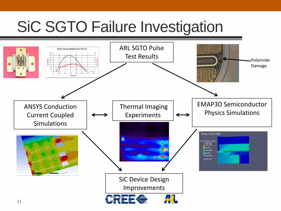
ARL SGTO Pulse Test Results
ANSYS Conduction Current Coupled
Simulations
EMAP3D Semiconductor Physics Simulations
Thermal Imaging Experiments
SiC Device Design Improvements
Polyimide Damage
SiC SGTO Failure Investigation

SiC Thermal Imaging Test
Pulse test SiC wire-bond devices
and use high speed thermal
imaging to determine hot spots
due to current concentration.
Pulsed Device Tester
ROI Temp(°C)
DT (°C)
1 97.8 74.8
2 73.8 50.5
3 50.7 27.9
4 53.1 30.2
5 34.1 10.9
X8Y6 Thermal Data: t0 + 862 ms

HIGH-PERFORMANCE COMPOSITES
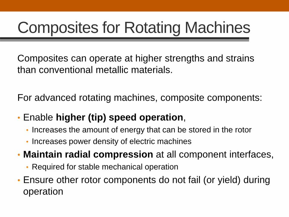
Composites for Rotating Machines
Composites can operate at higher strengths and strains
than conventional metallic materials.
For advanced rotating machines, composite components:
• Enable higher (tip) speed operation,
• Increases the amount of energy that can be stored in the rotor
• Increases power density of electric machines
• Maintain radial compression at all component interfaces,
• Required for stable mechanical operation
• Ensure other rotor components do not fail (or yield) during
operation

Different machines types
• Flywheels • Electrical machines

Design considerations
• Ultimate strength • High strength is often required for retention (outermost) bandings.
• In many electrical machines, must be thin because they reside in magnetic air gap.
• Unlike other components, outer bandings are not biased in compression at rest.
• Hoop modulus • High hoop modulus can lower deflection in the operating speed range.
• Intermediate modulus materials often have higher strain capability.
• Often the highest modulus composites do not have the highest strength.
• Peak service temperature • Composite components subject to heat loads
• Resistive or eddy current losses in electrical machines.
• Windage heating (in flywheels & electrical machines) is caused by friction when there is relative motion between the rotor and air gap (even when operating in partial vacuum).
• Composites typically have lower thermal conductivity than conventional metallic materials.
• Higher temperatures can accelerate viscoelastic response

Quality Control & Material Characterization
High performance rotating
machines demand:
– High-fidelity analytical tools
– Well-characterized materials
– Refined manufacturing and assembly
processes
CEM developed now standard
hydroburst test for:
– Quality control
– Assessing material lot variability
– Tensile strength, modulus
– Fatigue properties (elevated temp.)
– Establish Factor of Safety

Composite Arbors
• Arbors improve power and energy density by
focusing rotor weight at the outer rim where it is
most effective.
• Provide structural attachment of rotor rim to rotor
shaft
• Match rotor rim’s radial growth due to spin loads
• Transmit discharge torque
• Provide lateral stiffness for stable mechanical
operation
• Can support additional mechanical hardware for
connection of power and cooling circuits to the
rotor rim.
• Several arbor designs successfully validated in
spin test
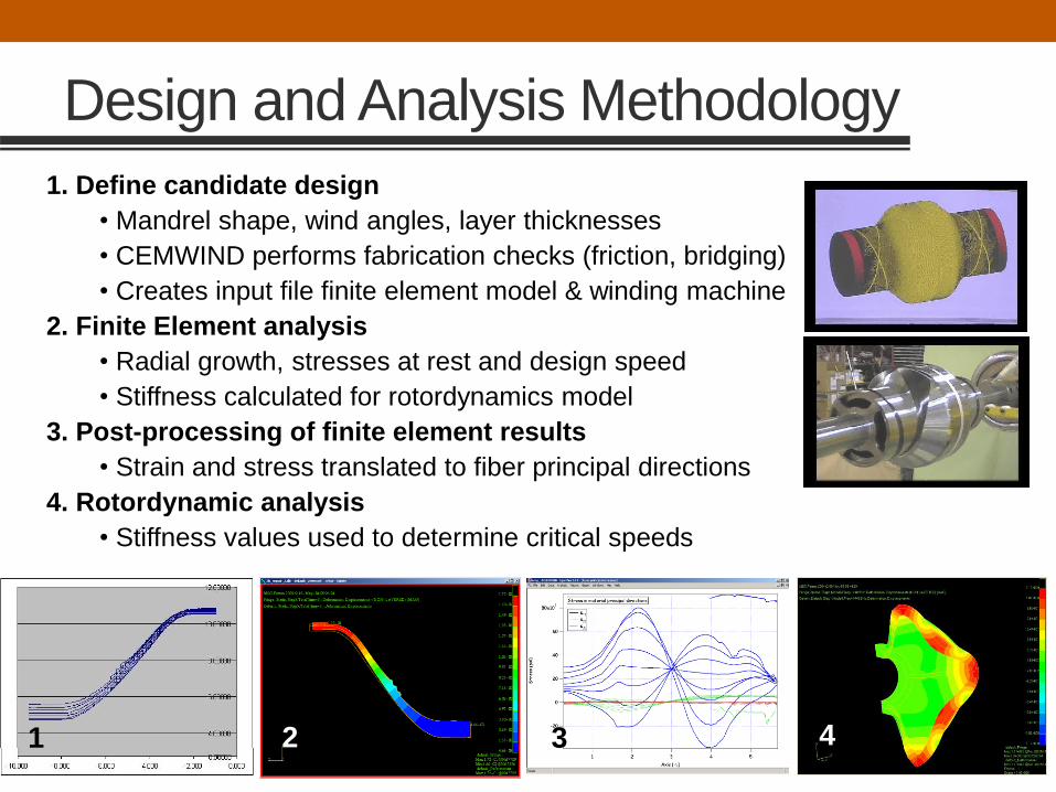
Design and Analysis Methodology
1. Define candidate design
• Mandrel shape, wind angles, layer thicknesses
• CEMWIND performs fabrication checks (friction, bridging)
• Creates input file finite element model & winding machine
2. Finite Element analysis
• Radial growth, stresses at rest and design speed
• Stiffness calculated for rotordynamics model
3. Post-processing of finite element results
• Strain and stress translated to fiber principal directions
4. Rotordynamic analysis
• Stiffness values used to determine critical speeds
1 2 3 4

Composite Characterization & Validation
• Structural tests (rap, deflection)
• Spin tests • Validate analysis tools, mechanical
performance, and can demonstrate how composite components fail.
• NASA Arbor Development (2003)• Demonstrated 50,000 rpm (1100 m/s)
• Overspeed test (1340 m/s) demonstrated 1.5 FoS
• Matched analysis predictions,
• Well behaved, stable operation
• DARPA Flywheel Program (2002)• Over 112,000 fatigue cycles completed
• Flywheel speed excursions from 27 to 36 krpm
• Peak tip speed 825 m/s
• Operating temperature of 140 F
• No structural degradation
• Army ATO Program (2004-2006)• Structural arbor tests: 1000 cycles (7.5k - 15k rpm)
• Multi-Arbor Spin Test: 333 cycles (2k - 12k rpm)
• Matched analysis predictions,
• Well behaved, stable operation

Summary
• Prior programs made significant investment in several critical technology areas• Refined performance simulations and modelling capabilities
• Advanced switching and controls for pulsed power systems
• High performance composite design and manufacture
• Specialized engineering knowledge exists including:• High-fidelity thermal modelling
• Active cooling solutions
• Unique manufacturing and assembly expertise for high-performance composite structures
• Large potential payoff of recent and near-term technology advances in a Navy system.

SHIP INTEGRATIONAngelo Gattozzi

Ship Integration of Large Pulsed Mission Systems
• Previous presentations have discussed the characteristics, and
potential benefits of Pulsed Alternators. They should be
evaluated as a possible option along with other technologies.
• Therefore, large pulsed mission systems can be supported by:
• Batteries
• Capacitors
• Flywheels
• Pulsed Alternators
• In all cases, the technology of choice needs to be integrated
with the ship power system. This will be discussed next
summarizing the results of three studies done for the US Navy
by the Center for Electromechanics of The University of Texas.

Storage Design Example 1:
Generalized Energy Magazine Concept
• System-level comprehensive evaluation of energy storage and power conversion systems for a notional Energy Magazine (EM).
• Its simulation results apply equally well to systems using a broad variety of generators, pulsed power loads, or ship bus loads, provided they can be represented by an equivalent mathematical model.
• This rather general approach, allows the definition of the performance attributes of an EM system and an estimate of its benefits independent of the specific technology adopted for its realization.
❖ Best solution may be a combination of different technologies

Basic Reference System Used
PPS
...
Generation
Storage
Ship busloads
Sh
ip’s
DC
Bu
s

Assumed Ship Bus Load Characteristics
• Ship Bus Loads. Aggregated load to represent power
requirements for all loads other than PPS. Stochastic
nature as bounded random walk:
• step amplitude changes – Less than 0.6 pu and greater than 0.3 pu
• number of points – 200 (1 point per second for a 200 second
simulation)
• maximum change point-to-point – 0.5 pu
• start to finish change – 0.3 pu.

• PPS load. Modeled as follows:• Number and rate of charge/discharge cycles - 16 times at a rate of 10
per minute
• Peak power – 0.3 pu
• Starting time – between 10 s and 30 s
• Duration of initial power ramp up in constant current mode – 2 s
• Duration of completion of charging in constant power mode – 3 s
• Duration of discharge time – 1 s
Assumed PPS Load Characteristics
Pulse detail
Constant
current
Constant
power
Discharge
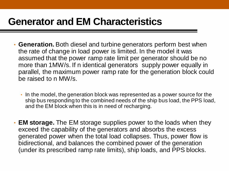
• Generation. Both diesel and turbine generators perform best when the rate of change in load power is limited. In the model it was assumed that the power ramp rate limit per generator should be no more than 1MW/s. If n identical generators supply power equally in parallel, the maximum power ramp rate for the generation block could be raised to n MW/s.
• In the model, the generation block was represented as a power source for the ship bus responding to the combined needs of the ship bus load, the PPS load, and the EM block when this is in need of recharging.
• EM storage. The EM storage supplies power to the loads when they exceed the capability of the generators and absorbs the excess generated power when the total load collapses. Thus, power flow is bidirectional, and balances the combined power of the generation (under its prescribed ramp rate limits), ship loads, and PPS blocks.
Generator and EM Characteristics

System and Variables Definition
Generation Ship Bus
Loads
PPSStorage
Bus
Vg
ig R
Vs
is R
VL
iLR
Vp
ipR
VB
Ship Loads
Profile
Generator Current
to Match Total Load
PPS Load
Profile
Targets:
Gen. Ramp Rate
Energy Set-point

First Result: Generalization of a Known Instability
Condition for stability:
𝑝𝐿 ≥ 𝑘 𝑖𝐿𝛼
where k = constant > 0 and > 1.0
in which case the differential impedance would be equal to
𝐿 =𝑑𝑣𝐿
𝑑𝑖𝐿= −
𝑘𝑖𝐿𝛼
𝑖𝐿2 +
𝑘𝛼𝑖𝐿𝛼−1
𝑖𝐿= 𝑘 𝛼 − 1 𝑖𝐿
𝛼−2
Given that it must be 𝑣𝐿𝑖𝐿 = 𝑝𝐿 𝑡 (Prescribed Power Load – PPL)
The differential impedance L is, therefore, given by
L = 𝑑𝑣𝐿
𝑑𝑖𝐿= −
𝑝𝐿
𝑖𝐿2 +
1
𝑖𝐿
𝑑𝑝𝐿
𝑑𝑖𝐿
Analysis shows that stability is possible if the following condition is met
First Result: Every load for which the power drawn is prescribed is potentially unstable

Second Result: Topology Induced Instability
In order for both iL and ip to be real, the following condition must be met:
vg−Rig2
4𝑅≥ greater of pL, pp
This leads to requiring that the following be both true at the same time:
pL ≤ pp pp ≤ pL
We conclude that the only way both iL and ip can always be real is if
pp = pL
which would be a very peculiar case, since pL and pp are presumed to
be quite arbitrary functions of time and independent of each other.
Second Result: PPLs located in close electrical proximity induce system instability

Solution Example

Actual Demonstration:
Railgun Shot from Microgrid
The electromagnetic gun system. The launcher is in the concrete bunker in the foreground and the longer concrete bunker contains the soft catch system for the projectiles. The capacitor bank is
adjacent to the gun and soft catch. Maximum stored energy of 12 MJ and muzzle energy of 2 MJ.

PFN Charging
with HESM
Centralized HESM
Distributed HESM
Ramped PFN
Charging
Hybrid PFN
Charging
Ramped PFN
Charging
Hybrid PFN
Charging
PFN = Pulse Forming Network (capacitor bank)
NOTE – Concept of operation (CONOPS): Both ship power system and
HESM power mission system at the same time
Storage Design Example 2:
Hybrid Energy Storage Module (HESM) for Railgun
HESM placement
Charging mode
(ramped vs. hybrid)

GEN
GEN
Zone 4
Load Center
Zone 3
Load Center
Zone 2
Load Center
Zone 1
Load Center
HESM Topology 1: Centralized
4.4 kV
240 Hz
4.4 kV
60 Hz
6 kVDC
6 kVDC
M
PFN power
supply
PFN
HESM motor/generator
HESM flywheel
HESM bi-direcitonal converter
Ppfn
PhesmPship
Isolated dc bus
[Stern] [Bow]
[Starboard]
[Port]
Single
feeder
Protective
device
A single compartment for
both PFN and HESM units
Legend*
GEN Synchronous generator
Circuit breaker
Bus, switchboard, or load center
AC/DC bi-directional power converter
M Flywheel, and motor / generator
DC-DC converter
Load
*Most symbols comply to IEEE Std 315-1975:
Graphic symbols for electrical and electronics diagrams
AC-DC converter
Protective device
5 MW 5 MW 5 MW 5 MW
The PFN and HESM are connected from zone 1 at an isolated dc bus. This
topology implies a single dc feeder to serve both the HESM and PFN,
compartmental proximity between the HESM and PFN, and the maximum storage
requirement for the single HESM unit.

The two HESM units considered for this topology are distributed over zones 2 and
3. Additional HESM modules can be considered. The advantages of the distributed
topology are the inter-zonal placements that allow the HESMs to supplement
generation ride-though, reduced failure probability under battle impact, and
simplified integration. Furthermore, each distributed HESM unit is smaller and
weighs less than the single HESM unit in the centralized case.
GEN
GEN
Zone 4
Load Center
Zone 3
Load Center
Zone 2
Load Center
Zone 1
Load Center[Stern] [Bow]
HESM Topology 2: Distributed
HESM 2 in Zone 2
HESM 1 in Zone 3
4.4 kV
240 Hz
4.4 kV
60 Hz
6 kVDC
6 kVDC
Legend*
GEN Synchronous generator
Circuit breaker
Bus, switchboard, or load center
AC/DC bi-directional power converter
M Flywheel, and motor / generator
DC-DC converter
Load
*Most symbols comply to IEEE Std 315-1975:
Graphic symbols for electrical and electronics diagrams
AC-DC converter
M
M
PFN power
supply
Ppfn
PFN
Phesm2
Phesm1
HESM 2 motor/generator
HESM 2 flywheel
HESM 1 motor/generator
HESM 1 flywheel
[Starboard]
[Port]
Feeder for
HESM unit 1
Feeder for
HESM unit 2
Feeder for
PFN
HESM 1 bi-direcitonal
converter
HESM 2 bi-
direcitonal
converter
5 MW 5 MW 5 MW 5 MW

Charging Profiles for Capacitor Bank PFNConstant Current vs. Hybrid (Constant Current and Constant Power)
Ppfn ≈ 40 MW
(peak)
Pship ≈ 17 MW
Phesm ≈ -23 MW
(discharging)
Ppfn ≈ 23 MW
(peak)
Phesm ≈ -6 MW
(discharging)
PFN Charging Variant 1:
Ramped Power (Constant Current)
PFN Charging Variant 2:
Hybrid Power
Phesm ≈ 17 MW
(charging)Phesm ≈ 17 MW
(charging)
Pship ≈ 17 MW
Constant current: more efficient but needs peak charging power of twice the average.
Hybrid constant current/constant power charging: reduces peak power demands on
the charging power supplies and energy storage sub-system.

Result Examples
• The notional load used in the comparison was a high energy, capacitor-based, Pulse Forming Network (PFN) operated with a repetition rate of 12 charge/discharge cycles per minute.
• Two hybrid solutions were evaluated:
1. One was based on lithium ion batteries and used a flywheel to improve the power delivery.
2. The other was a rotating-machine based HESM designed to mitigate the impact of transient (pulsed) loads on the ship’s distribution power system.
• An important finding was that the transient load could be effectively buffered with only the flywheel energy storage element.

Storage Design Example 3:
Back-fit of Laser Load on a DDG51 Destroyer
• Collaboration with NPS: laser power (30-125 kW)

Modeled Four Storage Scenarios for Laser
Lead-Acid Battery
Li-Ion Battery
Flywheel
Capacitor

General Structure of Models
ABT = Automatic Bus Transfer
BMS = Battery Management System
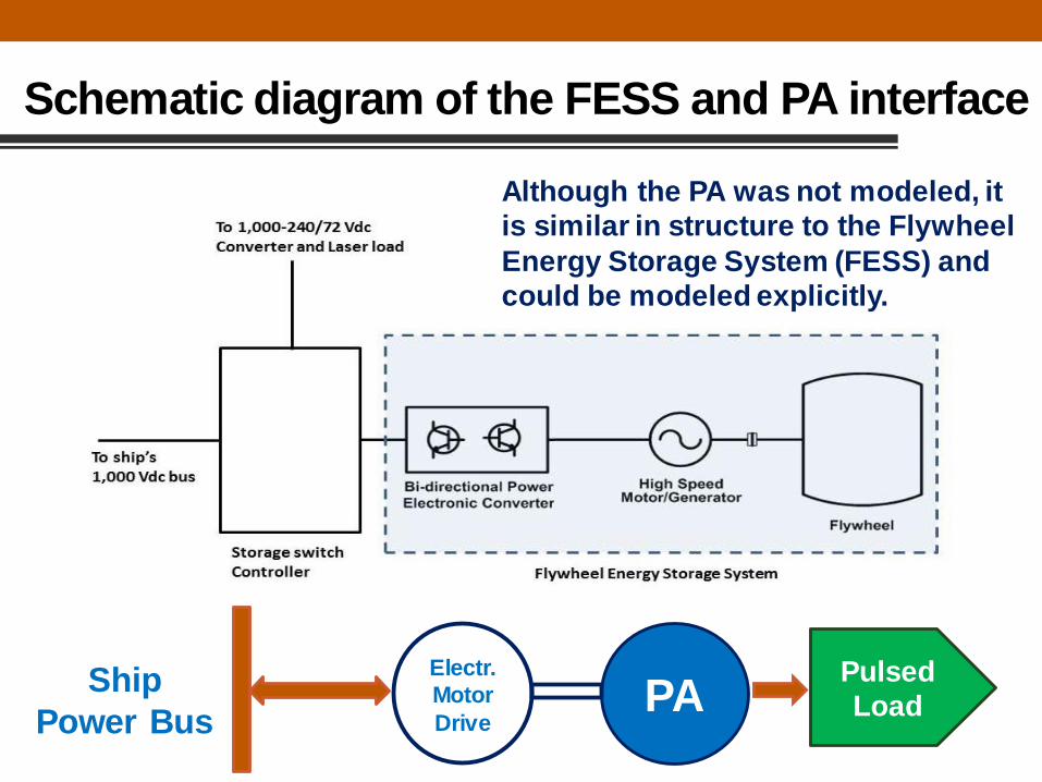
Schematic diagram of the FESS and PA interface
PAElectr.
Motor
Drive
Pulsed
LoadShip
Power Bus
Although the PA was not modeled, it
is similar in structure to the Flywheel
Energy Storage System (FESS) and
could be modeled explicitly.

Operation, Critical Parameters, Performance
In the given CONOPS, the mission system is powered only by the energy storage module, which in turn is recharged by the ship power system when the laser is not firing. Critical parameters are:
• The laser power rating
• The laser duty cycle
• The capacity of the available energy storage
• The charge-discharge characteristics of the energy storage
• The length of the engagement.
Thus, various scenarios need to be studied and performance optimized with respect to given metrics.
Ship Power Ship Power
Charging Discharging

Example of FESS Performance:
125 kW Laser, 40% Duty Cycle, 12 Shots/min
Lase
r O
utp
ut, k
WF
lyw
he
el, R
PM
Time, s
125 kW
25 kW
8,000 RPM
100 RPM
Impact on Ship’s Power Quality
Similar results are obtained for the
other storage technologies.
These models allow the optimization
of energy storage to support the
pulsed Laser load within the given
concept of operation.

• The PA is another alternative option for the Energy
Magazine (EM)
• Particularly suited for railgun
• Can be used as bus support (UPS, etc.) or for load
leveling function when not firing the railgun
• It should be evaluated along other EM options (batteries,
capacitors, flywheels)
• Like all other EM options, its stability characteristics
should be taken into account
Conclusions
SUMMARY REMARKSScott Pish
Center for Electromechanics
The University of Texas at Austin
8/14/17

Rotating Machines Show Promise
• The need to accommodate large transient loads and
mission systems is increasing.
• Each energy storage technology has merits, and multi-
dimensional solutions are likely.
• Pulsed Alternators are versatile rotating machines with
very high power and energy density supported by a firm
technology foundation.
• Generations of system and component level technology
development
• Design tools are benchmarked against multiple systems

Pulsed Alternators Gaining Attention
• Pulsed Alternators were the power supply of choice for
Army mobile platforms.
• But US research is this area has been idle for the last decade
• Focus of pulsed-power research in China for the past 20
years
• Two privately funded research groups have recently
investigated using a pulsed alternator for plasma research.
• A small commercial company is developing plans to use a
pulsed alternator for an application in the oil and gas
industry. The PA offers a compact, power and energy dense
mobile platform for remote well sites.
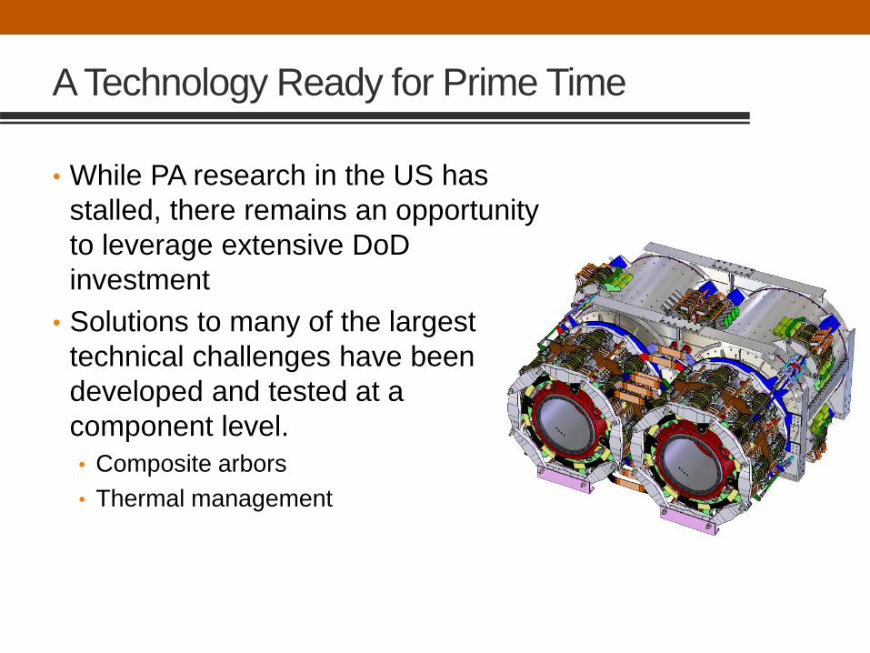
A Technology Ready for Prime Time
• While PA research in the US has
stalled, there remains an opportunity
to leverage extensive DoD
investment
• Solutions to many of the largest
technical challenges have been
developed and tested at a
component level.
• Composite arbors
• Thermal management

What are the Next Steps?
• Need to capture interim technological advancements
• Advanced switching and controls,
• Thermal management,
• Composite materials
• Need to update simulations for current SW platforms/
capabilities
• Need to transition expertise to future generations before it
is gone