pump p-920
TRANSCRIPT

User Manual
18-1125-54
Pump P-920
Terms and Conditions of Sale
Unless otherwise agreed in writing, all goods and ser-vices are sold subject to the terms and conditions ofsale of the company within the Amersham Biosciencesgroup which supplies them. A copy of these terms andconditions is available on request.
Should you have any comments on this product, wewill be pleased to receive them at:
Amersham Biosciences ABSE-751 84 UppsalaSweden
TrademarksDrop Design, ÄKTA, ÄKTAFPLC and UNICORN aretrademarks of Amersham Biosciences Limited.Amersham and Amersham Biosciences are trademarksof Amersham plc.
Microsoft, Windows and Windows 2000 are eitherregistered trademarks or trademarks of MicrosoftCorporation in the United States and/or other coun-tries.
Office Addresses
Amersham Biosciences AB
SE-751 84 UppsalaSweden
Amersham Biosciences UK Limited
Amersham PlaceLittle ChalfontBuckinghamshireEngland HP7 9NA
Amersham Biosciences Corp.
800 Centennial AvenueP.O. Box 1327Piscataway, N.J. 08855USA
Amersham Biosciences Europe Gmbh
Munzinger Strasse 9D-79111 FreiburgGermany
Amersham Biosciences KK
Sanken Building3-25-1 Hyakunincho, Shinjuku-kuTokyo 169–0073Japan
© Copyright Amersham Biosciences AB 2002- All rights reserved
Important user information
All users must read this entire manual to fully unders-tand the safe use of ÄKTAFPLC Pump P-920.
Safety symbols
The following Warning symbols highlights instruc-tions that must be strictly followed in order to avoidpersonal injury. Be sure not to proceed until theinstructions are clearly understood and all stated con-ditions are met.
WARNING! Read the instruction to avoidhazardous conditions.
Caution notices
Caution! The Caution sign highlights instructions orconditions that must be followed to avoid damage tothe product or other equipment. Be sure not to pro-ceed until the instructions are clearly understood andall stated conditions are met.
Notes
Note: The Note sign is used to indicate informationimportant for trouble-free and optimal use of the pro-duct.
CE Certifying
This product meets all requirements of applicable CE-directives. A copy of the corresponding Declaration ofConformity is available on request.
The CE symbol and corresponding declaration of con-formity, is valid for the instrument when it is:
– used as a stand-alone unit, or
– connected to other CE-marked Amersham Biosciences instruments, or
– connected to other products recommended or described in this manual, and
– used in the same state as it was delivered from Amersham Biosciences except for
alterations described in this manual.
WARNING! This is a Class A product. In a domestic environmentthis product may cause radio interference in whichcase the user may be required to take adequate measu-res.

Contents
1 Introduction
1.1 General ..................................................................................................................11.2 Accessories.............................................................................................................21.3 Safety .....................................................................................................................3
2 Installation
2.1 Unpacking..............................................................................................................42.2 General precautions ...............................................................................................42.3 Connecting electrical signal cables .........................................................................42.4 Connecting to UniNet-1 communication link ........................................................52.5 Connecting to supply voltage.................................................................................52.6 Rinsing tubing .......................................................................................................62.7 Connecting the inlet and outlet tubing...................................................................62.8 Running-in the new pump .....................................................................................72.9 Installation of accessories.......................................................................................8
3 Operation
3.1 On/off ....................................................................................................................93.2 Menu selection and settings ...................................................................................93.3 Menu overview ....................................................................................................103.4 Starting and stopping the pump...........................................................................113.5 Setting the flow rate and starting the pump.........................................................123.6 Setting concentration B ........................................................................................123.7 Running a simple gradient ...................................................................................133.8 Ending the run and storage..................................................................................133.9 Changing eluent ..................................................................................................143.10 Restart after power failure ...................................................................................15
4 Maintenance
4.1 Periodic maintenance ...........................................................................................164.2 Pump cleaning .....................................................................................................164.3 General care.........................................................................................................174.4 Changing rinsing solution ....................................................................................174.5 Testing leakage ....................................................................................................184.6 Replacing the piston seal .....................................................................................194.7 Replacing a damaged piston ................................................................................224.8 Cleaning the 6-port pump valve...........................................................................22
Pump P-920User Manual 18-1125-54 Edition AD i
Contents

5 Trouble-shooting
5.1 General ................................................................................................................235.2 Faults and actions ................................................................................................235.3 Error messages .....................................................................................................255.4 Checking the pump pressure ................................................................................27
A-D Reference information
A Description ..........................................................................................................28A.1 Module .....................................................................................................28A.2 Rear panel.................................................................................................28A.3 Fluid delivery ............................................................................................29A.4 6-port pump valve.....................................................................................29A.5 Pressure monitoring ..................................................................................30A.6 Protective covers .......................................................................................30A.7 Using an external chart recorder ...............................................................30
B Menus..................................................................................................................31B.1 Check menu ..............................................................................................31
B.1.1 Checking piston status ..............................................................31B.1.2 Checking the number of piston strokes.....................................31B.1.3 Checking mixer run time ..........................................................31B.1.4 Checking service mode..............................................................31
B.2 Setup menu ...............................................................................................32B.2.1 Set pressure limit.......................................................................32B.2.2 Set wash pressure limit .............................................................32B.2.3 Set pressure unit........................................................................32B.2.4 Set gradient base .......................................................................32B.2.5 Set mixer operation...................................................................32B.2.6 Set pulse compensation mode ...................................................33B.2.7 Set pressure offset .....................................................................33B.2.8 Setup language..........................................................................33B.2.9 Setup unit number ....................................................................33B.2.10 Setup display angle ...................................................................33
B.3 Alarm timer...............................................................................................34B.4 Service displays .........................................................................................34B.5 Menu and text overview ...........................................................................35
C Technical specifications .......................................................................................36C.1 Operating data ..........................................................................................36C.2 Physical data .............................................................................................36
D Accessories and consumables ...............................................................................38
Short instructions on back page
Pump P-920User Manual 18-1125-54 Edition ADii
Contents

About this manualThis manual comprises two parts; a practical part (sections 1 – 5)and a reference part (sections A – D). Sections 1 – 5 contain thenecessary information for installing, operating and maintaining the instrument.
Contents
Pump P-920User Manual 18-1125-54 Edition AD iii

Contents
Pump P-920User Manual 18-1125-54 Edition AD
iv

1 Introduction
1.1 GeneralPump P-920 is a high precision laboratory pump for use in liquidchromatography and other applications where constant flow isrequired. The performance of Pump P-920 is accurate andreproducible from low flow rates over the whole pressure range. Thechemical resistance of the pump allows its use with corrosive liquidsand organic solvents as well as aqueous solutions with high saltconcentrations.
Pump P-920 facilitates routine chromatography work.
It is utilised as system pump in ÄKTAFPLC™ chromatographysystems, or is used as a stand-alone unit. The flow rate is set locallywith a front dial, or from a PC running UNICORN™ 3.0 or higher.
Pump P-920 works with a wide range of columns and mediasupplied by Amersham Biosciences.
The pump can be used to form accurate and reproducible gradients.
In stand-alone configurations, setup parameters are stated in a Setupmenu, see Reference information B.2.
Pump P-920 features:
• A pressure sensor connected to pump module A and B.
• Pulse compensation
P-920
01
Pump P-920User Manual 18-1125-54 Edition AD 1
Introduction 1

Pump P-920User Manual 18-1125-54 Edition AD2
1.2 AccessoriesMixer M-925 can be connected to the pump. When P-920 isconnected to UNICORN, the mixer can be controlled on/off/autofrom UNICORN. When P-920 is run as a stand-alone unit, themixer is operated via the local user interface.
M-925
1 Introduction

1.3 Safety• The module is designed for indoor use only.
• Do not use in a dusty atmosphere or close to spraying water.
• Do not block the air inlet and outlet of the unit.
WARNING! Hands and fingers risk being squeezed between thepiston driving arm and the pump housing when running the pumpwithout the protective covers fitted.
WARNING! During normal operation, all protective covers overinternal capillaries, piston rods and glass cylinders must be inplace when running the pump.
WARNING! Incorrectly fitted tubing may loosen, causing a jet ofliquid to spray out. This is especially dangerous if hazardouschemicals are being used. Connect the tubing by first inserting thetubing fully, then tightening the connector fingertight.
WARNING! NaOH is injurious to health. Avoid spillage.
WARNING! When using hazardous chemicals, all suitableprotective measures, such as protective glasses, must be taken.
WARNING! The module must not be opened by the user. Itcontains high voltage circuits that can give a lethal electric shock.
WARNING! Always disconnect the power supply beforeattempting to replace any item on the module.
WARNING! The module must be connected to a grounded mainssocket.
Pump P-920User Manual 18-1125-54 Edition AD 3
Introduction 1

2 Installation
2.1 UnpackingUnpack the module and check the items against the supplied packinglist. Inspect the items for obvious damage that may have occurredduring transportation.
We recommend that all packing materials be retained if onwardtransport of the module is expected.
2.2 General precautionsThe module should be installed in a non-corrosive atmosphere.
The module should be located in a place of low temperaturevariations, away from heat sources, draughts and direct sunlight.
The module may be operated at normal ambient temperatures in therange +4 to +40 °C.
The module should be installed on a stable laboratory bench or inan ÄKTA™design chromatography system. To ensure correctventilation, a free space of 0.1 m is required behind and in front ofthe module. Place the module directly on the bench. To ensure thatthe ventilation inlet below the front is not blocked, do not place softmaterial under the module.
2.3 Connecting electrical signal cablesThe sockets for electrical signals are located on the rear panel.
Voltage
WARNING! For continued protection againstrisk of fire, replace only woth fuseof the specified type and current ratings
Frequency Power, max Fuse
100-200 V- 50-60 Hz 600 VA T 6,3 AL
Leakage current, max
3,5 mA
Mains
Mains output
UniNet 1
UniNet 2
Remote
PressureAnalogue out 0-1 V
CAUTION! Read the following information carefully to ensurethat the module is installed correctly.
Pump P-920User Manual 18-1125-54 Edition AD4
2 Installation

Pump P-920User Manual 18-1125-54 Edition AD 5
Installation 2Connecting to chart recorder (if used)1 Connect the chart recorder to the Mini-DIN-socket Pressure
Analogue out 0-1 V using the cable supplied.
Pin Signal1 Pressure signal2 Signal ground3–6 Not used (reserved for factory testing)
Note: The signal cable is delivered with protective covers on eachwire. Do not remove the protective covers from unused connectionsas a short circuit may disturb the measurement.
2 Set the recorder to 0–0.5 V input, full scale. 0.1 V corresponds to1 MPa.
2.4 Connecting to UniNet-1 communication linkWhen used in ÄKTAdesign chromatography system, the pump iscontrolled from a PC running UNICORN version 3.0 or higher viaUniNet-1 cables.
1 Connect two UniNet-1 cables to the UniNet-1 connectors. Themodule can be connected in series anywhere in the chain betweenthe PC and the termination plug. The UniNet-1 link connects, inseries, the PC with Pump P-920 and other modules. Thetermination plug is connected to the last module in the chain.
2.5 Connecting to supply voltage1 Make sure the on/off switch is in the OFF-position marked O.
2 Connect a mains cable between the module and a groundedmains socket. Any voltage from 100–240 V AC, 50–60 Hz can beused.
The module contains one user-replaceable fuse. See TechnicalSpecifications for fuse ratings.
WARNING! The module must be connected to a groundedmains socket.
CAUTION! The mains power to the ÄKTAdesignchromatography system must be switched OFF before connectingthe module to the UniNet-1 link.
12
345
6

2.6 Rinsing tubingThe rinsing tubing for the piston seals is installed at the factory andfilled with 20% ethanol. Check that the rinsing solution is presentbehind the pistons and that the rinsing tubing is connected andundamaged. Always use 20% ethanol as rinsing solution. Changerinsing solution at least every month.
2.7 Connecting the inlet and outlet tubingIn ÄKTAFPLC, the inlet and outlet tubing are installed at the factory.
When using P-920 in stand-alone applications, the inlet and outlettubing must be installed.
The outlet tubing (PEEK tubing, i.d. 0.50 mm, o.d. 1/16”) hastubing connectors attached at both ends.
The inlet tubings (A1, B1, teflon tubing i.d. 1.6 mm, o.d. 1/8”) havetubing connectors attached at one end and inlet filters at the otherend. The inlet filters have replacable filter inserts.
The inlet tubings are connected to the inlets marked A IN and B INon the pump valves and the outlet tubing is connected to the upperconnection on the pressure sensor marked OUT. The other end of theoutlet tubing is connected to a mixer inlet.
Pump P-920User Manual 18-1125-54 Edition AD6
2 Installation
Pump rinsing tubing
Pump rinsing tubing
Inlet pump module A Inlet pump
module B
Outlet tomixer
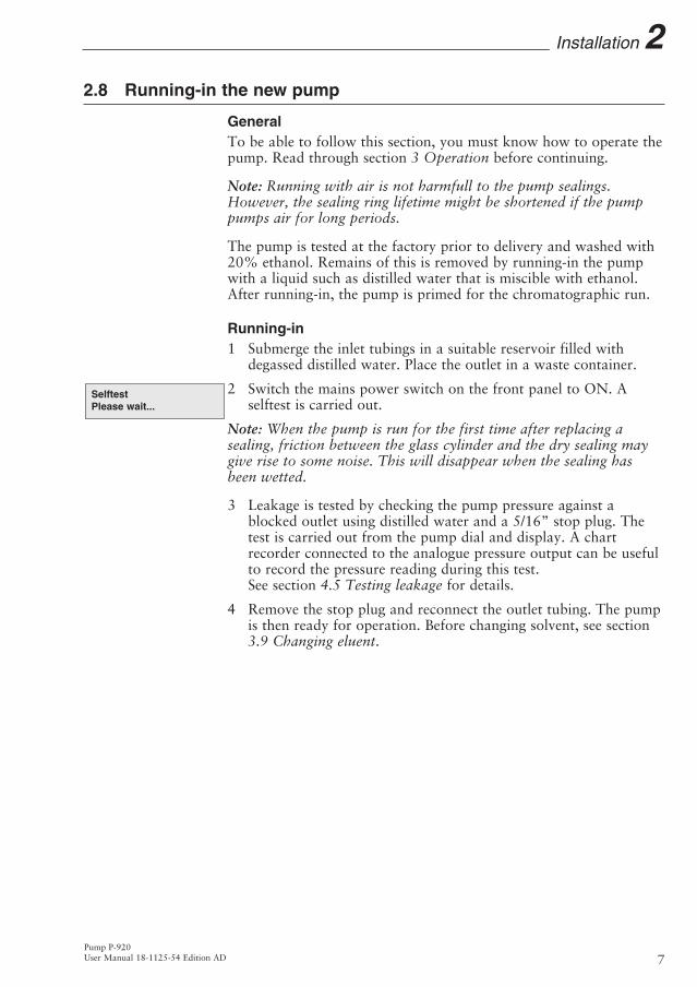
2.8 Running-in the new pump
GeneralTo be able to follow this section, you must know how to operate thepump. Read through section 3 Operation before continuing.
Note: Running with air is not harmfull to the pump sealings.However, the sealing ring lifetime might be shortened if the pumppumps air for long periods.
The pump is tested at the factory prior to delivery and washed with20% ethanol. Remains of this is removed by running-in the pumpwith a liquid such as distilled water that is miscible with ethanol.After running-in, the pump is primed for the chromatographic run.
Running-in1 Submerge the inlet tubings in a suitable reservoir filled with
degassed distilled water. Place the outlet in a waste container.
2 Switch the mains power switch on the front panel to ON. A selftest is carried out.
Note: When the pump is run for the first time after replacing asealing, friction between the glass cylinder and the dry sealing maygive rise to some noise. This will disappear when the sealing hasbeen wetted.
3 Leakage is tested by checking the pump pressure against ablocked outlet using distilled water and a 5/16” stop plug. Thetest is carried out from the pump dial and display. A chartrecorder connected to the analogue pressure output can be usefulto record the pressure reading during this test. See section 4.5 Testing leakage for details.
4 Remove the stop plug and reconnect the outlet tubing. The pumpis then ready for operation. Before changing solvent, see section3.9 Changing eluent.
SelftestPlease wait...
Pump P-920User Manual 18-1125-54 Edition AD 7
Installation 2

2.9 Installation of accessoriesInstall Mixer M-925 as follows:
01
M-925
UniNet 1
UniNet 2
Remote
PressureAnalogue out 0-1 V
CAUTION! Before connecting the mixer M-925, make sure thepower switch is in OFF position.
-Loosen the two screws
-Mount the attached mounting bracket with the two screws
Use one of the mounting rails
Pump P-920User Manual 18-1125-54 Edition AD8
2 Installation
The mixer isconnected tothe UniNet 2connector
Stop plug
Mixer outlet
Inlet tubing A1
Inlet tubing B1
Outlet tubing
3 Operation
3.1 On/offSwitch on the module at the mains switch on the front panel. At switch on, the module performs a selftest. Several beeps are heard during this process. If an error is detected, an error message is shown.
Name and software version number is shown for 2 seconds.
The selftest takes approximately 1/2 minute. When start-up is completed with no errors, the display shows the main menu with thepump in End mode. All parameters are factory set to default values.
3.2 Menu selection and settings
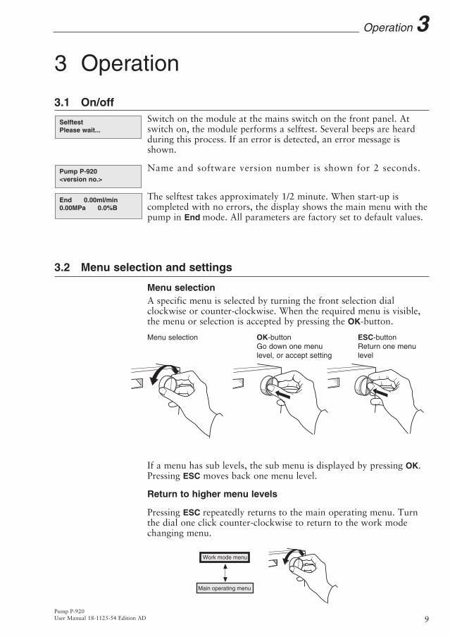
Menu selectionA specific menu is selected by turning the front selection dialclockwise or counter-clockwise. When the required menu is visible,the menu or selection is accepted by pressing the OK-button.
Menu selection OK-button ESC-buttonGo down one menu Return one menu level, or accept setting level
Select sub-menu Return one menu level
If a menu has sub levels, the sub menu is displayed by pressing OK.Pressing ESC moves back one menu level.
Return to higher menu levels
Pressing ESC repeatedly returns to the main operating menu. Turnthe dial one click counter-clockwise to return to the work modechanging menu.
Work mode menu
Main operating menu
End 0.00ml/min0.00MPa 0.0%B
Pump P-920<version no.>
SelftestPlease wait...
Pump P-920User Manual 18-1125-54 Edition AD 9
Operation 3

Selecting a valueA cursor below a text or numerical value shows what is affected bythe dial. To increase the value, turn the dial clockwise. To decreasethe value, turn the dial counter-clockwise. The value can be reset byturning the dial several clicks counter-clockwise.
To simplify entering large numerical values, the cursor moves up tothe next digit if the dial is turned quickly in one direction. Thecursor moves back one place to the right every two seconds if thedial is not turned. The text or numerical value displayed is acceptedby pressing OK. To cancel, press ESC.
3.3 Menu overviewWork mode changing menu. From here the pump is started, stopped, held, paused and continued. This menu is accessed from all positions by turning the dial one click counter-clockwise. The appearance of this menu depends on the current mode.
Main operating menu. The menu is accessed from all positions by pressing ESC repeatedly.
Setting flow rate in ml/min.
Setting concentration and gradient values.
Wash program selection. Individual pump cylinder assemblies or a complete pump wash can be selected.
Pump synchronisation selection. This means that the pump cylinder(s) are run to one stop position. Individual pump cylinder assemblies or a complete pump synchronisation can be selected.
Change piston direction selection. Individual piston direction or both piston directions can be selected.
Check internal operating values. See Reference information sectionB.1.
Setup language, pressure limits and unit, etc. See Reference information section B.2.
Set different timer options. The pump can be started or stopped at set times. See Reference information section B.3.
Alarm/Timer 12:30:52
Setup
Check
Change Direction
Pump Sync 20ml/min
Pump Wash 20ml/min
Set Conc./Gradient(0.0%B)
Set Flow Rate(0.00ml/min)
Run 13.40ml/min2.00MPa 45.5%B
End 1.00ml/minRun
Pump P-920User Manual 18-1125-54 Edition AD10
3 Operation
Setup Hi Press Limit(5.00MPa) 5.00
Parameter
Current value New value to be set

3.4 Starting and stopping the pump
Main operating menuThe main operating menu shows the current flow rate together with work mode indication, pressure and %B, if used. The available workmodes are:
Run The pump is running with set flow rate.End The pump is not running. Flow rate and gradient are reset.Pause The pump is stopped but the set flow rate and the
gradient are retained.Hold The gradient is held at the value displayed and the
pump continues to run.
Continue Not a work mode. Used to continue from Hold or Pause.
Work mode changing menuWork mode changes are made in the work mode changing menu above the main operating menu (turn dial counter-clockwise). The current work mode is shown in the upper left corner of the display. Available actions are shown at the lower right. There are four different displays for this menu and the menu displayed will depend on the current mode (see below). When a new mode is selected, theappearance of the menu will change.
Pressing OK in a work mode changing display selects the underlined work mode. Different work modes are selected by turning the dial.
• To start the pump, select Run and press OK.
• To stop the pump, select End and press OK.
Hold 1.00ml/minEnd Continue Pause
Pause 1.00ml/minEnd Hold Continue
End 1.00ml/minRun
Run 1.00ml/minEnd Hold Pause
Run 13.40ml/min2.00MPa 45.5%B
WARNING! All protective covers over internal capillaries, pistonrods and glass cylinders must be in place when running the pump.
WARNING! Incorrectly fitted tubing may loosen, causing a jetof liquid to spray out. This is especially dangerous if hazardouschemicals are being used. Connect the tubing by first insertingthe tubing fully, then tightening the connector fingertight.
Pump P-920User Manual 18-1125-54 Edition AD 11
Operation 3
Current workmode
Availableactions forthe currentwork mode
Preparation before starting
1 Check that there is sufficient solvent present for the run, and thatthe solvent filter is fully immersed. If the eluent is to be changed,see section 3.9 Changing eluent.
Note: The pump may not work if the buffer vessels are sealed, or ifthey are placed too far below the pump inlets. Do not close thevessels off completely. Place the buffer vessels on the workbench oron the buffer tray on top of ÄKTAFPLC.
2 Check that there is rinsing liquid (20% ethanol) in the rinsingsystem (behind the piston heads).
3 Set the pressure limit. Refer to section B.2.1 in Referenceinformation. If the pressure limit is exceeded, the pump isstopped.
Emergency stopUse the front power switch, or disconnect the mains supply from thepump.
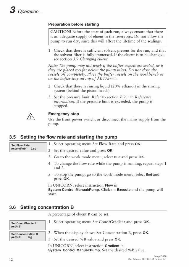
3.5 Setting the flow rate and starting the pump1 Select operating menu Set Flow Rate and press OK.
2 Set the desired value and press OK.
3 Go to the work mode menu, select Run and press OK.
4 To change the flow rate while the pump is running, repeat steps 1and 2.
5 To stop the pump, go to the work mode menu, select End andpress OK.
In UNICORN, select instruction Flow inSystem Control:Manual:Pump. Click on Execute and the pump willstart.
3.6 Setting concentration BA percentage of eluent B can be set.
1 Select operating menu Set Conc./Gradient and press OK.
2 When the display shows Set Concentration B, press OK.
3 Set the desired %B value and press OK.
In UNICORN, select instruction Gradient inSystem Control:Manual:Pump. Set the desired %B value.
Set Concentration B(0.0%B) 5.0
Set Conc./Gradient(0.0%B)
Set Flow Rate(0.00ml/min) 2.50
CAUTION! Before the start of each run, always ensure that thereis an adequate supply of eluent in the reservoirs. Do not allow thepump to run dry, since this will affect the lifetime of the sealings.
Pump P-920User Manual 18-1125-54 Edition AD12
3 Operation
!

Pump P-920User Manual 18-1125-54 Edition AD 13
Operation 33.7 Running a simple gradient
Gradients can be run in time or volume base. The default is timebase. To change base, see B.2.4 in section Reference information.
The gradient is run from currentconcentration to target concentration,over a set time or volume. Thegradient can be set in any operatingmode.
1 Select operating menu Set Conc./Gradient and press OK.
2 When the display shows Set Concentration B, turn the dial to select operating menu Set Gradient Length and press OK.
3 Set the desired value and press OK.
4 Turn the dial to select operating menu Set Gradient Target and press OK. Set the desired gradient target value in %B and press OK. If the pump is in work mode Run, the gradient starts immediately.
5 At the end of the set gradient time, the pump continues to run atthe target concentration.
In UNICORN, select instruction Gradient inSystem Control:Manual:Pump. In the Parameters window set Targetand Length. Click on Execute.
3.8 Ending the run and storageOvernight storage: The pump can be left filled with a buffer.
Note: If buffers or water are stored at room temperature, bacterialgrowth may occur.
If no further runs are planned, the pump should be washedimmediately with pure eluent. If aqueous buffers have been used,washing with pure distilled water is particularly important toprevent salt precipitation.
Weekend and long term storage: Wash the pump with water andthen fill it with 20% ethanol.
Set Gradient Target(0.0%B) 50.0
Set Gradient Length(0.0min) 8.0
Set Conc./Gradient(0.0%B)
0%
100%
Target concentration
Current concentration
Start ofgradient
Gradient length
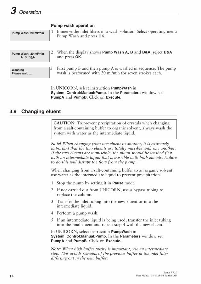
Pump wash operation1 Immerse the inlet filters in a wash solution. Select operating menu
Pump Wash and press OK.
2 When the display shows Pump Wash A, B and B&A, select B&Aand press OK.
3 First pump B and then pump A is washed in sequence. The pumpwash is performed with 20 ml/min for seven strokes each.
In UNICORN, select instruction PumpWash in System Control:Manual:Pump. In the Parameters window setPumpA and PumpB. Click on Execute.
3.9 Changing eluent
Note! When changing from one eluent to another, it is extremelyimportant that the two eluents are totally miscible with one another.If the two eluents are immiscible, the pump should be washed firstwith an intermediate liquid that is miscible with both eluents. Failureto do this will disrupt the flow from the pump.
When changing from a salt-containing buffer to an organic solvent,use water as the intermediate liquid to prevent precipitation.
1 Stop the pump by setting it in Pause mode.
2 If not carried out from UNICORN, use a bypass tubing toreplace the column.
3 Transfer the inlet tubing into the new eluent or into theintermediate liquid.
4 Perform a pump wash.
5 If an intermediate liquid is being used, transfer the inlet tubinginto the final eluent and repeat step 4 with the new eluent.
In UNICORN, select instruction PumpWash inSystem Control:Manual:Pump. In the Parameters window setPumpA and PumpB. Click on Execute.
Note: When high buffer purity is important, use an intermediatestep. This avoids remains of the previous buffer in the inlet filterdiffusing out in the new buffer.
CAUTION! To prevent precipitation of crystals when changingfrom a salt-containing buffer to organic solvent, always wash thesystem with water as the intermediate liquid.
WashingPlease wait......
Pump Wash 20 ml/minA B B&A
Pump Wash 20 ml/min
Pump P-920User Manual 18-1125-54 Edition AD14
3 Operation

3.10 Restart after power failureIf the power supply to the pump is interrupted, it automaticallyrestarts after performing a selftest when power is restored. All valuesunder the Setup menu are retained. Other operating values, e.g. flowrate, are reset.
Pump P-920User Manual 18-1125-54 Edition AD 15
Operation 3

4 MaintenanceNote: The piston seals have a limited lifetime depending on the flowrate, pressure and eluents used. The seals are regarded asconsumables and are available as a sealing kit. The wear of thepiston seals is not covered by the warranty of the pump. A typicallifetime is around 1000 run hours.
4.1 Periodic maintenance
Interval Action (see procedures below)Daily General careMonthly Change rinsing solution (20% ethanol)Every two months Leakage testWhen required Fixing leaking connections
Replacing the piston sealsReplacing a damaged pistonCleaning or replacingthe 6-port pump valve
4.2 Pump cleaningPerform a pump wash using a cleaning or sanitising agent. Thestandard recommendation is to use 1 M NaOH and then wash outwith buffer or distilled water.
WARNING! NaOH is injurious to health. Avoid spillage.
CAUTION! Only spare parts approved or supplied by AmershamBiosciences may be used for maintaining and servicing themodule.
WARNING! Incorrectly fitted tubing may loosen, causing a jet ofliquid to spray out. This is especially dangerous if hazardouschemicals are being used. Connect the tubing by first inserting thetubing fully, then tightening the connector fingertight.
WARNING! Always disconnect the power supply beforeattempting to replace any item on the module duringmaintenance.
Pump P-920User Manual 18-1125-54 Edition AD16
4 Maintenance

4.3 General careInspect the pump daily for eluent leaks.
If, at any time, air bubbles are trapped in a cylinder assembly, purge the pump by manually changing the direction of the piston when the piston reaches its end position. Change direction several times until the air bubbles are removed.
General recommendations for all eluentsIt is essential that all liquids passing through the pump are clean,pure and degassed. Impure or dirty eluents will not only causebaseline noise and drift, but also block the channels in the 6-portpump valves, shortening their lifetime. Degassing prevents formationof air bubbles, which can cause baseline noise, drift anddeteriorating gradient formation.
Additional recommendations for aqueous eluentsAfter running with an aqueous eluent, the pump should always bethoroughly washed with pure, distilled water to prevent saltprecipitation.
4.4 Changing rinsing solutionThe rinsing solution should be changed monthly. Use a 20%solution of ethanol/distilled water.
1 Remove the rinsing tubing between the glass cylinders for boththe A and B pump.
2 Select 50%B and run the pump at 20 ml/min to flush out theused rinsing solution. Allow the pump to perform a couple ofstrokes to remove as much rinsing solution as possible from theglass cylinders.
3 Stop the pump when the pistons are at the middle of the glasscylinders.
4 Refit the rinsing tubing to the lower cylinders in each pumpmodule.
5 Add fresh rinsing solution to the lower cylinders by submergingthe rinsing tubing open ends in rinsing solution and starting thepump. Continue to run until approximately half of the cylinderchambers are filled. Stop the pump.
6 Refit the rinsing tubing to the upper cylinders.
7 Run the pump and allow a couple of strokes to wash out asmuch contamination from the old rinsing solution as possible.
8 If required, repeat steps 1-6 one or two times, to ensure that allcontamination is washed out.
Change directionA B A&B
Pump P-920User Manual 18-1125-54 Edition AD 17
Maintenance 4
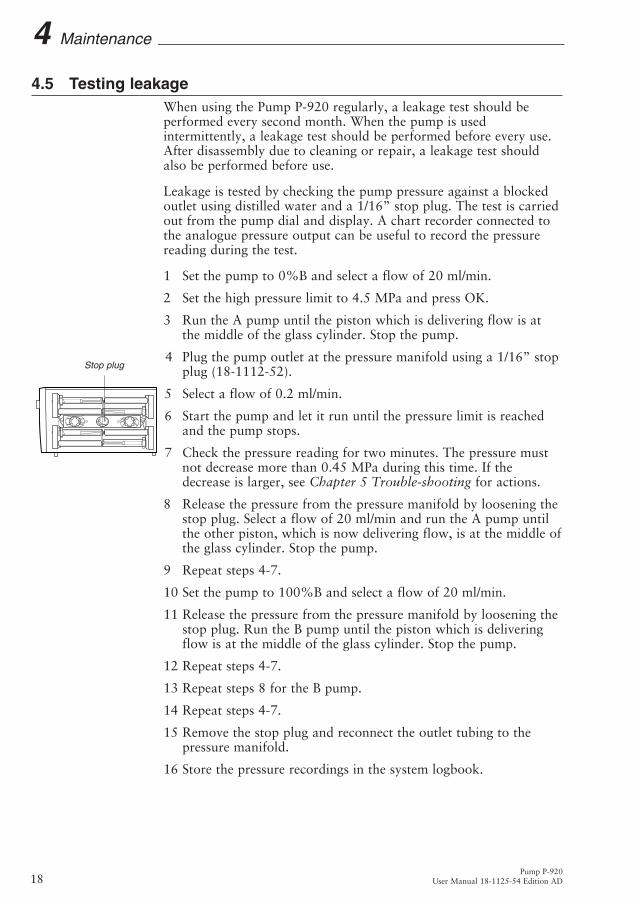
4.5 Testing leakageWhen using the Pump P-920 regularly, a leakage test should beperformed every second month. When the pump is usedintermittently, a leakage test should be performed before every use.After disassembly due to cleaning or repair, a leakage test shouldalso be performed before use.
Leakage is tested by checking the pump pressure against a blockedoutlet using distilled water and a 1/16” stop plug. The test is carriedout from the pump dial and display. A chart recorder connected tothe analogue pressure output can be useful to record the pressurereading during the test.
1 Set the pump to 0%B and select a flow of 20 ml/min.
2 Set the high pressure limit to 4.5 MPa and press OK.
3 Run the A pump until the piston which is delivering flow is atthe middle of the glass cylinder. Stop the pump.
4 Plug the pump outlet at the pressure manifold using a 1/16” stop plug (18-1112-52).
5 Select a flow of 0.2 ml/min.
6 Start the pump and let it run until the pressure limit is reached and the pump stops.
7 Check the pressure reading for two minutes. The pressure must not decrease more than 0.45 MPa during this time. If the decrease is larger, see Chapter 5 Trouble-shooting for actions.
8 Release the pressure from the pressure manifold by loosening thestop plug. Select a flow of 20 ml/min and run the A pump untilthe other piston, which is now delivering flow, is at the middle ofthe glass cylinder. Stop the pump.
9 Repeat steps 4-7.
10 Set the pump to 100%B and select a flow of 20 ml/min.
11 Release the pressure from the pressure manifold by loosening thestop plug. Run the B pump until the piston which is deliveringflow is at the middle of the glass cylinder. Stop the pump.
12 Repeat steps 4-7.
13 Repeat steps 8 for the B pump.
14 Repeat steps 4-7.
15 Remove the stop plug and reconnect the outlet tubing to thepressure manifold.
16 Store the pressure recordings in the system logbook.
Pump P-920User Manual 18-1125-54 Edition AD18
4 Maintenance
Stop plug

4.6 Replacing the piston sealIf there are signs of leakage between piston seal and glass cylinder,replace the piston seal of the leaking pump cylinder.
A seal leakage will gradually fill up the rinsing chamber completely,causing excess fluid to leak out around the rinsing tubing connections.
Note: Before disassembling the pump mechanism, move all inputbuffer bottles to below the level of the pump pistons to preventsiphoning.
Note: Always replace the piston seals on both piston heads of apump module at the same time.
Required spare parts and toolsSeal kit containing (see Reference information D for code numbers): • Piston seal kit containing two piston seals,two gaskets and two wipers.• M6 wrench (included in ÄKTAFPLC tool kit).• 2.5 mm Allen key (included in ÄKTAFPLC tool kit).• U-wrench NV 5.5 (included in ÄKTAFPLC tool kit).
Note: After new sealings have been installed, check the pump forleakage. See section 4.5 Testing leakage.
Replacement instruction
1 Use operating menu Setup Pulsecomp. to check that pulse compensation is off, see Section B.2.6. If not, select off. Otherwise, adjustment is not possible.
2 Start the pump and run until the piston head reaches the middle of its cylinder. Stop the pump by setting it to END work mode.
Run 1.00ml/min
Setup Pulsecomp.(on) on off
CAUTION! Read the following instructions carefully. Avoidfitting the individual parts of the pump cylinder assemblyincorrectly. Ensure that the orientation of each part is correctbefore continuing with the next instruction.
CAUTION! Do not disassemble the pump mechanism unlessthere is good reason to believe that the seal is leaking. Alwaysensure that sufficient spare components are available beforeattempting to replace the piston seal. We do not recommendrefitting a used piston seal after removal.
Pump P-920User Manual 18-1125-54 Edition AD 19
Maintenance 4

Pump P-920User Manual 18-1125-54 Edition AD20
4 Maintenance
3 Switch OFF the pump at the mains power switch on the front panel.
4 Remove the protective perspex cover by unscrewing the fixing screws.
5 Remove the protective metal cover over the piston rod by gently pressing it together while pulling it off.
6 Remove the rinsing tubing. Also remove the tubing cover by undoing the two Philips screws.
7 Disengage the piston rod from the driving arm by loosening the stop screw with the 2.5 mm Allen key.
8 Unscrew the locking screw for the pump cylinder assembly in a clock-wise direction and remove it. Disconnect the inlet and outlet tubings from the pump cylinder assembly.
9 Unscrew the M3 nuts from the support rods. Carefully remove the glass cylinder together with the end piece and gently pull out the piston.
10 Remove the piston seal using a needle. Be careful not to damage the piston head during this operation. Fit the new seal by hand.
11 The wiper is removed by pressing it out from the rod. Press a new wiper onto the rod. The hole on the wiper should point towards the pump head.
12 Wet the piston head with distilled water and push it into theglass cylinder.
13 Change the end piece gasket located between the end piece andthe glass cylinder. Use a spatula to remove the worn gasket.
14 Place the flat edge of the support rod assembly on a flat surface.
15 Mount the end piece on the support rod assembly so the tubingconnectors are parallel to the flat edge.
16 Mount the glass cylinder with the piston and the wiper onto theend piece. Check that the rinsing tubing connector pointsupwards.
CAUTION! Do not push the piston at an angle to the cylinder anddo not twist the piston.
Covers Philips screws
Rinsing tubing
Piston rodstop screws
Locking screw
Inlet andoutlet (rear) connections
Support rods
M3 nuts
Glass cylinder
Piston
Piston head
End pieceWiper
Piston seal

17 Make sure that both the end piece gasket and the wiper are inposition. Insert the two support rods into the holes in the endpiece. When the glass cylinder is properly seated, tighten the twoM3 nuts gently.
18 Refit the pump cylinder assembly. Check that the end piecerinsing tubing connector points towards you. Connect the inletand outlet tubings to the pump cylinder assembly. Check theassembly alignment and the connections carefully to eliminate therisk of glass cylinders bursting when pressure is applied.
19 Tighten the locking screw for the pump cylinder assembly andpull the piston rod to the end piece.
20 Switch on the pump with the mains power switch on the frontpanel. After the selftest, run the pump at a low flow rate so thatthe piston rod slips into the hole in the driving arm. Continue torun the pump until the 6-port pump valve switches. Just as thevalve switches, stop the pump.
21 Engage the piston rod in the driving arm by tightening the stopscrew with the Allen key.
22 Fill the rinsing system with 20% ethanol and replace the rinsingtubing.
23 Replace the tubing cover, the protective cover over the piston rodand the perspex cover. Make sure that no capillary is stuckbetween covers and the pump housing.
24 Run in the new sealings as described in section 2.8 Running-inthe new pump.
WARNING! Hands and fingers risk being squeezed between thepiston driving arm and the pump housing when running the pumpwithout the protective covers fitted.
Pump P-920User Manual 18-1125-54 Edition AD 21
Maintenance 4
Rinsing tubing connector
Piston rod
Outlet connector
Inlet connector
Locking screw
Pump cylinder assembly
End piecePull

Pump P-920User Manual 18-1125-54 Edition AD22
4 Maintenance
4.7 Replacing a damaged pistonTypical symptoms of a damaged piston are observed as excessivepiston seal wear, unstable pressure, a reduction in the flow or, insome cases, noise as the piston moves. The piston should beremoved, examined for damage or salt precipitation and thenreplaced with a new piston if necessary.
If a damaged piston has been in operation, the piston seal will bedestroyed and should also be replaced. To replace the piston and theseal, follow the instructions in section 4.6 Replacing the piston seal.
In addition to the spare parts listed in section 4.4, a pump headcomplete and possibly, if scratches are found inside the glasscylinder, a glass cylinder are also required (see Referenceinformation D for code numbers).
4.8 Cleaning the 6-port pump valveFaulty operation of the 6-way pump valve is usually indicated by noflow and that the pressure sensor gives no indication that the backpressure has increased. The probable cause is that one or morechannels are blocked.
Identify the relevant pump cylinder assembly by observing whichpump head is not delivering flow.
First, try to clean the inlet channel in–place by disconnecting theinlet tubing and the tubing from the corresponding pump cylinderassembly. Clean the channels in the valve by flushing nitrogen inreverse flow direction through the valve. Observe the capillarymarkings when reconnecting the tubing.
If this does not correct the problem, call Amersham Biosciences forservice.
CAUTION! Change the solvent to distilled water and flush outall salt before flushing the 6-port pump valve.
WARNING! Incorrectly fitted tubing may loosen, causing a jet ofliquid to spray out. This is especially dangerous if hazardouschemicals are being used. Connect the tubing by first inserting thetubing fully, then tightening the connector fingertight. Finallytighten the internal connectors a further 1/4 turn using the keysupplied.

5 Trouble-shooting
5.1 GeneralWhen contacting Amersham Biosciences for support, state theversion number of the module. This is shown for 2 seconds duringstart-up. The version and model can also be checked by using theCheck Service Mode operating menu.
We recommend you make a pressure recording since muchinformation can be gained from the pressure trace. See section 5.4Checking the pump pressure, for more information.
5.2 Faults and actionsIf the suggested actions do not correct the fault, call AmershamBiosciences.
Fault ActionLarge spillage over/into 1 Unplug the mains inlet cable.system/module 2 Clean and dry the system/module with a dry cloth or paper.
If necessary, tilt the system/module backwards to drain.3 Call Amersham Biosciences local service for advice.
No text on the front display 1 Check that the mains cable is connected and the power switch is in ON-position I.
2 Check the mains power supply.3 Check the mains inlet fuse.
Erratic flow, noisy baseline signal, irregular pressure traceAir bubbles passing 1 Check that there is sufficient eluent present in the through or trapped in the pump reservoirs.
2 Check all connections for leakage.
6-port pump valve 1 Follow the instructions in section 4.8 Cleaning the not functioning correctly 6-port pump valve.
2 Clean the valve in-place. If improvement is not seen, call Amersham Biosciences for service.
Piston seal leaking 1 Replace the piston seal according to the instructions in section 4.6 Replacing the piston seal.
WARNING! The module must not be opened by the user. It contains high voltage circuits that can give a lethal electricshock.
Pump P-920User Manual 18-1125-54 Edition AD 23
Trouble-shooting 5

Fault Action
Blockage or partial blockage 1 Flush through to clear blockage.2 If necessary, replace tubing.3 Check inlet tubing filter. It can become clogged if unfiltered
buffers or samples are applied.See instructions for flushing through at the end of the run in section 3.8 Ending the run and storage.
Liquid leaking from the Wiper and/or end piece gasket incorrectly fitted or worn.pump cylinder assembly 1 Replace or re-install the faulty part(s).
Low eluent flow and noise 1 Disassemble the pump cylinder assembly and examine the as the pistons move piston seal and glass cylinder walls according to section
4.6 Replacing the piston seal. Replace if necessary.2 If the glass cylinder walls are scratched, check the piston
seal. Ensure that the piston rinsing system is always used, especially when working with aqueous buffers with high salt concentrations.
3 Check the piston for damage. If damaged, replace the piston according to section 4.7 Replacing a damaged piston.
4 Never reinstall used or old parts that may be worn.
Leaking connection and/or 1 Unscrew the tubing connector and check if it is worn or crystalised material around incorrectly fitted. If so, replace the connector.a connector 2 Tighten the connector properly.
Error in external chart recorder 1 Check the chart recorder according to its manual.
Pump P-920User Manual 18-1125-54 Edition AD24
5 Trouble-shooting

5.3 Error messagesIf the suggested actions do not correct the fault, call AmershamBiosciences.
Message Action1 Reboot system.2 If error remains, notify instrument support.
1 Switch off the module.2 Check the UniNet-2 connections to the mixer.3 Check the mixer.4 Switch on the module.
1 Switch off the module.2 Check all UniNet 2 connections.3 Switch on the module.
1 Switch off the module.2 Switch on the module.3 If still persistent, call service.
1 Check high pressure limit setting.2 Check the column (may be blocked).3 Check the flowpath for blockage.1 Check low pressure limit setting2 Check the column (may be leaking).3 Check the flowpath for leakage.4 Check for air in the pump.1 Switch off the module and let it cool.2 Clean or clear the air inlets.3 Switch on the module and check that the fan is running.1 Call service.
84 ERROR endsensorspump B call service
83 ERROR endsensorspump A call service
82 WARNING pumpoverheated check fan
81 WARNING Pump underpressure
80 WARNINGPump overpressure
76 Error in valveBCont./Call service
75 Error in valveACont./Call service
73 WARNING UniNet2Check connection
72 Error in UniNet2Check units
71 Error in mixerCheck mixer
70 WARNING no mixerCheck connection
35 ERROR in softwarenotify instr support
34 ERROR in softwarenotify instr support
33 ERROR in softwarenotify instr support
1 ERROR in softwarenotify instr support
Pump P-920User Manual 18-1125-54 Edition AD 25
Trouble-shooting 5

1 Reboot system.2 If error remains, call service.
1 Call service for recalibration.
1 Select other instruction, or change mode (End, Run or Pause).
1 Reboot system.2 If error remains, notify instrument support.
1 Low pressure limit can not be set higher than high pressure limit. Reset limit.
1 Low pressure limit for warning can not be set higher than high pressure limit for warning. Overlapping ranges due to hysterersis are not allowed. Reset limit.
1 Release pressure in system before setting analogue output voltage.
1 Call instrument support.
1 Full scale pressure must be greater than zero. Reset value.3636 Value must begreater than 0
3620 Error hardwarenotify instr suppor
3610 Discon pressurethen set analog V.
3605 Low lim>hi-limHysteresis
3600 Low lim>hi-lim
3624 Error softwarnotify instr support
3622 Error softwarnotify instr support
3621 Error softwar notifyinstr support
3510 Error softwarnotify instr support
3411 Error softwarnotify instr support
3410 Error softwar notifyinstr support
3401 Error softwarnotify instr support
3400 Error software notifyinstr support
3300 Error softwarenotify instr support
88 Not allowed incurrent mode.
86 ERROR in EEPROMRecalib. all values
85Failed to set offset
Pump P-920User Manual 18-1125-54 Edition AD26
5 Trouble-shooting

1 The key was pressed during self-test, or is faulty.2 Switch off the module.3 Switch on the module.
1 Switch off the module.2 Check all connections.3 Switch on the module.
1 Switch off the module.2 Check all UniNet 1 and UniNet 2 connections.3 Switch on the module.
5.4 Checking the pump pressureTo check the pump function, make a recording of the pressure on achart recorder, or check the pressure in UNICORN. This pressurerecording is more sensitive than the reading on the display. Byobserving the piston running indicator in Check menu (see sectionB.1.1) together with the pressure trace, the pump cylinder assemblywhich is functioning abnormally can be identified.
There can be several causes of an abnormal pressure recording, forexample:
• partially blocked solvent filters• leaking connections• piston seal leakage• 6-port pump valve malfunction• piston and glass cylinder damaged• flow restrictor blocked• column blocked• mixer blocked• sample injection valve blocked.
ERROR number 118
ERROR number 106-108
ERROR number 120-121
ERROR number 109-113
ERROR number 100
ERROR key (OK+Esc)
ERROR key (Esc)
ERROR key (OK)
Pump P-920User Manual 18-1125-54 Edition AD 27
Trouble-shooting 5
Reference informationA Description
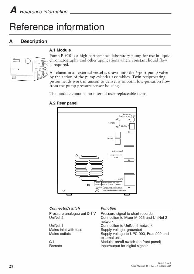
A.1 Module Pump P-920 is a high performance laboratory pump for use in liquidchromatography and other applications where constant liquid flowis required.
An eluent in an external vessel is drawn into the 6-port pump valveby the action of the pump cylinder assemblies. Twin reciprocatingpiston heads work in unison to deliver a smooth, low-pulsation flowfrom the pump pressure sensor housing.
The module contains no internal user-replaceable items.
A.2 Rear panel
Connector/switch FunctionPressure analogue out 0-1 V Pressure signal to chart recorderUniNet 2 Connection to Mixer M-925 and UniNet 2
networkUniNet 1 Connection to UniNet-1 networkMains inlet with fuse Supply voltage, groundedMains outlets Supply voltage to UPC-900, Frac-900 and
external units0/1 Module on/off switch (on front panel)Remote Input/output for digital signals
Voltage
WARNING! For continued protection againstrisk of fire, replace only woth fuseof the specified type and current ratings
Frequency Power, max Fuse
100-200 V- 50-60 Hz 600 VA T 6,3 AL
Leakage current, max
3,5 mA
Mains
Mains output
UniNet 1
UniNet 2
Remote
PressureAnalogue out 0-1 V
P-920
01
Pump P-920User Manual 18-1125-54 Edition AD28
A Reference information

Auxiliary equipment with digital signal interface can be connected tothe 9-pole D-SUB female REMOTE connector (5 V TTL signalsonly).
Pin Signal Function1-4 Digital input 1-4 Active status=low or closed terminal to pin 55 0 V Signal ground6-9 Digital ouput 1-4 Active status=+5 V in reference to pin 5
When used in combination with UNICORN and the ÄKTAFPLCstrategy, 4 digital inputs and 4 digital outputs can be handled via theREMOTE connector. Pins 1–4 are used as inputs, and pins 6–9 as outputs. All input/output signals are 5 V TTL signalswith ground reference to pin 5.
A.3 Fluid deliveryPumping action is provided by a stepper motor, through a gear boxand a ball screw, to two alternating pistons mounted on the right-hand side of the pump module.
The driving mechanism is located behind the side panel. The pistonsreciprocate in two high precision glass cylinders. The pistons aredriven so that one piston draws in solvent while the other expelsolvent.
The change of piston direction is controlled by opto-electronicswitches at the end positions. These switches also control the 6-portpump valve movement.
Each piston consists of three parts:
• head
• sealing
• connecting rod
The pump cylinder assembly is resistant to corrosive fluids and iseasy to disassemble when servicing.
A.4 6-port pump valveThe 6-port pump valve is a motorised rotary valve driven by a DC-motor through a gear box. The function of the valve is to control thesolvent flow to and from the cylinder assemblies. The valve has sixtubing connections.
The 6-port pump valve operates automatically when the pistonsreach their end positions. The end positions are detected by opto-electronic switches. The valve is also operated when manual changeof direction is ordered via the front dial.
12345
6789
Pump P-920User Manual 18-1125-54 Edition AD 29
Reference information A
In stand-alone applications, all connections except IN and OUT arefitted at the factory. When used in ÄKTAFPLC chromatographysystems, the IN and OUT connections are also connected at thefactory.
A.5 Pressure monitoringThe pressure generated by the pump is continuously monitored by apressure transducer housed in an outlet manifold block. The pressuretransducer generates a signal which is proportional to pumppressure. This signal is read by UNICORN via the UniNet 1connection, and is also displayed on the front panel display. It is alsofed to the rear panel connector Pressure analogue out 0-1 V, where 0.1 V corresponds to 1 MPa.
The pressure transducer has two main functions:
• to continuously measure the operating pressure
• to sense excessive pressure that could damage the columns
If the pressure builds up to the set limit, the pump automaticallyshuts down and an alarm is given.
A.6 Protective covers
Pump P-920 is equipped with covers to protect both the user and thepump from accidental damage.A perspex cover is fitted over the fluid delivery side of the pump.The perspex cover is fixed with screws.
Metal covers are located over the moving part of the piston rods outside the glass cylinders. These covers are held in position by springaction.
A.7 Using an external chart recorderThe facility for recording the actual pressure at the pump outlet canbe used for recording the pressure during an overnight run and forchecking the pump function for any abnormality.
The external chart recorder output for pressure is 0–1 V, where 0.1 V corresponds to 1 MPa.
WARNING! All protective covers over internal capillaries, pistonrods and glass cylinders must be in place when running the pump.
Pump P-920User Manual 18-1125-54 Edition AD30
A Reference information
B Menus
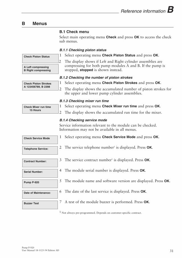
B.1 Check menuSelect main operating menu Check and press OK to access the checksub menus.
B.1.1 Checking piston status
1 Select operating menu Check Piston Status and press OK.
2 The display shows if Left and Right cylinder assemblies arecompressing for both pump modules A and B. If the pump is stopped, stopped is shown instead.
B.1.2 Checking the number of piston strokes
1 1 Select operating menu Check Piston Strokes and press OK.
2 The display shows the accumulated number of piston strokes for the upper and lower pump cylinder assemblies.
B.1.3 Checking mixer run time
1 1 Select operating menu Check Mixer run time and press OK.
2 The display shows the accumulated run time for the mixer.
B.1.4 Checking service mode
Service information relevant to the module can be checked.Information may not be available in all menus.
1 Select operating menu Check Service Mode and press OK.
2 The service telephone number1 is displayed. Press OK.
3 The service contract number1 is displayed. Press OK.
4 The module serial number is displayed. Press OK.
5 The module name and software version are displayed. Press OK.
6 The date of the last service is displayed. Press OK.
7 A test of the module buzzer is performed. Press OK.
1 Not always pre-programmed. Depends on customer-specific contract.
Buzzer Test
Date of Maintenance:
Pump P-920
Serial Number:
Contract Number:
Telephone Service:
Check Service Mode
Check Mixer run time15 Hours
Check Piston StrokesA 123456789, B 2398
A Left compressingB Right compressing
Check Piston Status
Pump P-920User Manual 18-1125-54 Edition AD 31
Reference information B

B.2 Setup menuSelect main operating menu Setup and press OK to access the setupsub menus.
B.2.1 Set pressure limit
Sets high and low pressure limits. When the limit is reached, thepump is set in Pause mode, a buzzer sounds and an error messageOverpressure (for ascending pressure) or Underpressure (for descendingpressure) is shown. This message has to be confirmed by pressingOK.
1 Select sub menu Setup Hi Press Limit, press OK.
2 Set the value, press OK.
3 Repeat steps 1 and 2 for Setup Lo Press Limit.
Note: Low pressure limit cannot be set above High pressure limit and High pressure limit cannot be set below Low pressure limit. The low pressure limit check is delayed at start-up to allow for system pressure build-up.
B.2.2 Set wash pressure limit
Sets wash pressure high limit. When the limit is reached, the pump isset in Pause mode, a buzzer sounds and an error message Washoverpressure is shown. This message has to be confirmed by pressingOK.
1 Select sub menu Setup Wash Press Lim, press OK.
2 Set the value, press OK.
B.2.3 Set pressure unit
Sets the pressure unit used in the display.
1 Select sub menu Setup Pressure Unit, press OK.
2 Select either MPa, bar or psi, press OK.
B.2.4 Set gradient base
Sets the base for the gradient to either time or volume.
1 Select sub menu Setup Gradient Base, press OK.
2 Select either time or volume, press OK.
B.2.5 Set mixer operation
Sets the condition of the mixer connected to the pump.
1 Select sub menu Setup Mixer, press OK.
2 Select either on, off or auto, press OK. “auto” means the mixer is running when the pump is in Run, Pause or Hold mode.
Setup Mixer(auto) on off auto
Setup Gradient Base(time) time volume
Setup Pressure Unit(bar) MPa bar psi
Setup Wash Press Lim(5.00MPa) 4.50
Setup Lo Press Limit(0.00MPa) 1.00
Setup Hi Press Limit(5.00MPa) 4.50
Pump P-920User Manual 18-1125-54 Edition AD32
B Reference information

B.2.6 Set pulse compensation mode
Sets the condition for pulse compensation.
1 Select sub menu Setup Pulsecomp., press OK.
2 Select either on or off, press OK.
B.2.7 Set pressure offset
Allows pressure offset calibration.
1 Select sub menu Setup Press Offset, press OK.
2 A warning message is shown that the pressure must be zero in thepressure transducer to perform the calibration.
3 Press OK to acknowledge or Esc to cancel. When acknowledged, the display returns to Setup Press Offset.
4 Press OK to perform the calibration.
B.2.8 Setup language
Sets the language used in the display.
1 Select sub menu Setup Language and press OK.
2 Select the desired language.GB = EnglishD = GermanF = FrenchE = SpanishI = Italian
B.2.9 Setup unit number
The unit number is the identification the pump has on the UniNet-1communication link. It should correspond to the number set inUNICORN for the pump. The number should be set to 0 if onepump is used. If more than one pump is used, they must all havedifferent identification numbers. Factory default setting=0.
1 Select sub menu Setup Unit Number, press OK.
2 Select unit number (0–25), press OK.
B.2.10 Setup display angle
Sets the display angle to compensate for different viewing heights.
1 Select main menu Setup, press OK.
2 Select sub menu Set Display Angle, press OK.
3 Select display angle (->\ Up, ->| Mid or ->/ Down), press OK. Set Display Angle( ->|) ->\ ->| ->/
Setup Unit Number(0)
Setup language
Calib Press Offset
Calib Press Offset
Note! Zero pressure
Setup Press Offset
Setup Pulsecomp.(on) on off
Pump P-920User Manual 18-1125-54 Edition AD 33
Reference information B

B.3 Alarm timerYou can set the alarm function to either a fixed alarm time or use acount-down timer. The pump can be started or stoppedautomatically, or an alarm can sound, at the set time. It is notpossible to set both an alarm time and the count-down timer.Current values are shown in parentheses.
1 Select main menu Alarm/Timer, press OK.
2 Set the action to take place. Press OK to select action. Buzzerwill generate an audible alarm for 15 s with a message. Run will start the pump at the set flow rate. End will stop the pump. Each generates one beep and a message.
3 Use the sub menu Set Alarm if you want to set an alarm at a fixed time. Press OK to enter the time in the form HH.MM.SS. Press the OK button after entering each time unit.
4 If you want to set a count-down time, turn the dial to select sub menu Set Timer. Press OK to enter the count-down value in the form HH.MM.SS. Press the OK button after entering each time unit.
5 Press ESC button to return to the Alarm/Timer menu, which now shows the set alarm time or count-down time as BuzzerHH:MM:SS.
6 When the alarm time is due or the count-down timer reaches 00:00:00, an alert display is shown and the module beeps, until the OK button is pressed. A second alert display is shown, until the OK button is pressed
The alarm timer is based on the internal module clock, which can beset in the Set Clock menu located after the Alarm/Timer menu. The clock will be reset when power is turned OFF.
A set alarm/timer function can be reset by pressing OK in the menu Alarm/Timer off?
B.4 Service displaysThe module has service displays for use by authorised service personnel. If the service display Enter Access Code! is accidentally selected, press the ESC-button to return to the normal operating menus.
Enter Access Code!
Alarm/Timer off?
Set Clock
12:41:29 12:41:49
Alarm/Timer 12:30:52
Set Timer
Set Alarm 12:32:21
Alarm/Timer Action
Alarm/Timer 12:30:52
B Reference information
Pump P-920User Manual 18-1125-54 Edition AD34

Pump P-920User Manual 18-1125-54 Edition AD 35
Reference information BB.5 Menu and text overviewTurn Dial to select menus on same level. Press OK to acknowledgeselection. Press Esc to move up one menu level. Press Esc again tomove up further.
Setup Hi Press Limit(5.00MPa) 4.50
Setup Lo Press Limit
Set Conc./Gradient(0.0%B)
Setup
Run 23.40ml/min
Set Flow Rate
Check
Run 1.00ml/min Pause 1.00ml/min Hold 1.00ml/minEnd 1.00ml/min
Set Concentration B(0.0%B) 5.0
Set Gradient Length
Alarm/Timer 12:30:52 Alarm/Timer action
Set Gradient Target(0.0%B) 10.0
Telephone Service:012345678901
Contract Number:
Serial Number:
Pump P-920
Date of Maintenance:
Buzzer Test
Set Alarm 12:32:21
Set Timer
Set Clock
Alarm/Timer off?
Check Piston Status A Left compressingB Right compressing
Pump Wash 20ml/min Pump Wash 20ml/min Washing Warning! Pump paused
Pressure at 3 ml/min
Pump Sync 20ml/min Pump Sync 20ml/min Synchronizing pumps Warning! Pump paused
Pressure at 3 ml/min
Change direction Change direction
Check Piston StrokesA 123456789, B 3467
Check mixer run time15 hours
Check Service Mode
Setup Wash Press Lim(5.00MPa) 4.50
Setup Pressure Unit
Setup Gradient Base
Setup Mixer(auto) off on autoSetup Pulsecomp.
Setup Press Offset
Setup language
Setup Unit number
Set Display Angle
Note! Zero pressure
Calib Press Offset
Calib Press Offset

C Technical specifications
C.1 Operating dataFlow rate range
isocratic mode 0.01–20 ml/min in steps of 10 µl/mingradient mode 0.1–20 ml/min in steps of 1 µl/min
Pressure range 0–5 MPa (50 bar, 725 psi)Pressure pulsation Max. 6% (dP/P) during pump strokepH stability range 1–13, (1–14 <1 day exposure)Viscosity Max 5 cP for complete flow rate range. At
reduced flow rate (£5 ml/min); 10 cPFlow rate reproducibility
flow rate 0.5-10 ml/min rsd < 0.2%Gradient composition
accuracy between turnings ±2% at 0.5–5 ml/min and <5 MPaaccuracy during turnings ±2% at 0.5–5 ml/min and 0.5-2.0 MPareproducibility rsd <0.5% at 0.5–20 ml/min and <5 MPa
Leakage <0.5 ml/min (pump module A and B each)Pressure sensor
range 0–7 MPaoffset error Max. ±0.05 MPascale error Max. ±2%
C.2 Physical dataDelay volumes
per pump cylinder assembly 10 ml
Inlet tubing Tubing connector for 1/8“ o.d. tubing Outlet tubing Fingertight connector, 1/16” o.d.Fuse specification T 6.3 ALControl Stand-alone or from a PC running
UNICORN version 3.0 or higher, viaUniNet 1 cable connection.
Degree of protectionhousing IP 20
Wetted materialspiston head PEEKpiston rod Titaniumglass cylinder Borosilicate glasspump seal Simriz6-port valve PEEK, titanium and ruby/sapphire.
Chemical resistance The wetted parts are resistant to organic solvents and salt buffers commonly used in chromatography of biomolecules.
Power requirement 100–240 V AC, 50–60 HzPower consumption 600 VA including accessoriesDigital input 5 V TTL low or contact closure
(see section A.2 for pin connections)Digital output TTL, open collectorsRecorder output 0–1 V full scale (0.1 V corresponds to 1
MPa)Functions Languages available; English, German,
Spanish, French, Italian
Pump P-920User Manual 18-1125-54 Edition AD36
C Reference information

Display 2 rows with 20 characters eachEnvironment +4 to +40 °C
20–95% relative humidity84–106 kPa (840–1060 mbar)
Dimensions, H x W x D 150 x 260 x 370 mmWeight 18 kg
Reference information C
Pump P-920User Manual 18-1125-54 Edition AD 37

Pump P-920
38 User Manual 18-1125-54 Edition AD
D Accessories and ConsumablesItem Quant./pack A/C* Code no.Sealing kit, containing two sealingstwo gaskets and two wipers 1 C 18-1032-16Pump head complete 1 A 18-1032-15Glass cylinder 1 A 18-1512-01Internal tubing kit P-920 1 C 18-1128-70Rinsing tubing, 1.1 mm i.d., 3.1 mm o.d. 2 m A 18-1032-11Union 1/16” female/M6 male, PEEK 6 A 18-1112-57
Fingertight connector 1/16”, for PEEK tubing o.d. 1/16” 10 A 18-1112-55
Union, 1/16” male/1/16” male,for 1/16” o.d. tubing, PEEK 10 A 18-1120-92
Stop plug, 5/16”, PEEK 5 A 18-1112-50
Stop plug, 1/16”, PEEK 5 A 18-1112-52
Tubing cutter 1 A 18-1112-46U-wrench, M6 1 A 19-7481-01U-wrench, 1/4” 1 A 18-1112-45Allen key, 2.5 mm 1 A 19-4442-01Signal cable, 6 pin mini-DIN - open 1 A 18-1110-64Chart Recorder REC 111, 1 channel 1 A 18-1132-32Chart Recorder REC 112, 2 channel 1 A 18-1132-33
*) A=accessories C=consumables
D Reference information

Contents
Pump P-905
User Manual 18-1125-54 Edition AD 39

Contents
Pump P-905
40 User Manual 18-1125-54 Edition AD Dec
embe
r 20
02


Short instructionsThe following short instructions are intended as a guide tousers who are fully familiar with the safety precautions andoperating instructions described in this manual. These shortinstructions assume that the module is installed according tothe installation instructions.
Select OK ESC
P-920
01
TC
info
rmat
ion
ab,
Upp
sala
. P
rinte
d in
Sw
eden
by
TK
i U
ppsa
la A
B
1 Switch on the module with the mains switch on the rear panel.
2 A self-test is performed. The version number is shown for two seconds.
3 The main operating menu is shown.
4 Set the flow rate.
5 Start the pump by setting it in RUN mode.
6 The main operating menu is shown.
7 Set concentration and gradient.
8 Start a gradient by setting the Gradient Length and Gradient Target.
9 Stop the pump by setting it in END mode.
End 2.50ml/minRun
Set Gradient Target(0.0%B) 10.0
Set Gradient Length
Set Conc./Gradient(0.0%B) 10.0
Run 2.50ml/min2.0MPa 0.0%B
End 2.50ml/minRun
Set Flow Rate(0.00ml/min) 2.5
End 0.00ml/min
Pump P-920
Selftest