purchase description family of improved load bearing equipment
TRANSCRIPT
10 May 2011 **UPDATED 14 July 2011**
This update supersedes all previous versions
PURCHASE DESCRIPTION
FAMILY OF IMPROVED LOAD BEARING EQUIPMENT
This document is approved for use by all Departments and Agencies of the Department of Defense (DoD). 1. SCOPE 1.1 Description. This document covers the Family of Improved Load Bearing Equipment (FILBE) utilized by the United States Marine Corps (USMC). The load bearing equipment system is designed to allow Marines to carry equipment needed in support of combat operations. The system is modular in order to meet the unique needs of the warfighter. The load bearing equipment system shall maximize the ability to carry combat loads efficiently, minimize the burdens of weight, improve overall system compatibility and increase the combat effectiveness of the user.
1.2 Classification. The load bearing equipment shall be of the following Class: Class 1 – Coyote 498 Class 2 – Woodland MARPAT Class 3 – Desert MARPAT Class 4 – Snow MARPAT Class 5 – OCP
Class 6 – Tan 499 Beneficial comments (recommendations, additions, deletions) and any pertinent data which may be used in improving this document, which is not in reference to any active solicitations, should be addressed to: Trevor Scott, (508) 233-5580, DSN 256-5580, [email protected], US Army Natick Soldier RDEC, Kansas Street, Natick, MA 01760
1

1.3 FILBE Components. The FILBE shall consist of the following components:
A) USMC Pack System a. Main Pack
(1) Frame (2) Shoulder Harness Assembly (3) Hip Belt (4) Main Bag
b. Assault Pack c. Assault Pouch d. Sustainment Pouch (Qty. 2) e. Hydration Pouch (Qty. 2) f. Hydration Carrier g. Hydration Bladder System
(1) Hydration Bladder (2) Hydration Tube with Cover (3) Tube Holder (4) Hydration Bite Valve with Cover
h. Sternum Cinch i. Sub-Belt (also known as “Girth Hip Belt”) j. Repair Kit k. USMC Pack Instruction Card
B) Chest Rig a. USMC Chest Rig
C) USMC Equipment Pouches D) USMC Holster E) USMC Corpsman Assault Pack F) Individual Water Purification System
2. APPLICABLE DOCUMENTS 2.1 General. The documents listed in this section are specified in Sections 3 and 4 of this specification. This section does not include documents cited in other sections of the specification or recommended for additional information or as examples. While every effort has been made to ensure the completeness of this list, document users are cautioned that they must meet all specified requirements documents cited in Sections 3 and 4 of this specification, whether or not they are listed. All part numbers are listed in alphabetical order by manufacturer, not by preference. 2.2 Government Drawings. The following drawings form a part of this specification to the extent specified herein. DRAWINGS U.S. Army Natick Research, Development and Engineering Center 2-1-2525 - Woodland MARPAT Pattern 4 color (Coyote 476) 2-1-2526 - Woodland MARPAT Pattern 4 color (Green 474 with EGA symbol)
2

2-1-2527 - Woodland MARPAT Pattern 4 color (Black 477) 2-1-2528 - Woodland MARPAT Pattern 4 color (Khaki 475) 2-1-2529 - Desert MARPAT Pattern 4 color (Light Tan 479) 2-1-2530 - Desert MARPAT Pattern 4 color (Urban Tan 478) 2-1-2531 - Desert MARPAT Pattern 4 color (Light Coyote 481 with EGA symbol) 2-1-2532 - Desert MARPAT Pattern 4 color (Highland 480) 2-6-111 - GRENADE GAUGE ASSEMBLY 2-6-112 - GRENADE GAUGE 2-6-113 - STEM 2-6-114 - LEVER 2-6-101 - LADDERLOCK, ONE INCH 2-6-102 - SLIDE, ONE INCH 2-4-0101 - FASTENER, ONE INCH 2-1-2242 - 40 MM PYROTECHNIC GRENADE GAUGE 2-1-2243 - 40 MM HIGH EXPLOSIVE GRENADE GAUGE 2-6-110 - M16 30 ROUND MAGAZINE GAUGE 2-4-0102 - MOLDED LOCKING CARIBINER 2-6-329 - MOLLE POCKET ATTACHMENT 2.3 Chest Rig Drawings. The following drawings form a part of this specification to the extent specified herein. DRAWINGS U.S. Army Natick Research, Development and Engineering Center 2-6-0801 - MARINES, CHEST RIG, ASSEMBLY 2-6-0792 - ATTACHING STRAP, ASSEMBLY (MARINES) 2-6-0852 - IMTV/PC ATTACHING STRAP, ASSEMBLY 2-6-0794 - HARNESS ASSEMBLY (TAP) 2-3-0632 - SINGLE BAR SIDE RELEASE FASTENER, 1 INCH 2-6-0798 - QUICK ATTACH, BUCKLE 1 INCH 2-6-0799 - SINGLE, BAR SIDE RELEASE BUCKLE, 1 INCH 2-6-234 - IDENTIFICATION/INSTRUCTION, LABELS MOLLE II 2.4 Pouch Drawings. The following drawings form a part of this specification to the extent specified herein.
DRAWINGS U.S. Army Natick Research, Development and Engineering Center
2-6-0761 - GROUND ILLUMINATION FLARE SINGLE POUCH ASSEMBLY 2-6-0762 - PATTERNS, ILLUMINATION FLARE SINGLE 2-6-0763 - SHOTGUN SHELL AMMUNITION POUCH ASSY, 12 GA., 10 ROUND 2-6-0764 - PATTERNS, SHOTGUN AMMUNITION POUCH 2-6-0765 - UTILITY/SQUAD AUTOMATIC WEAPON (SAW) AMMO. POUCH ASSEMBLY WITH DIVIDER 2-6-0766 - PATTERNS, UTILITY/SQUAD AUTOMATIC WEAPON POUCH 2-6-0767 - SMOKE GRENADE POUCH ASSEMBLY
3

2-6-0768 - PATTERNS, SMOKE GRENADE FBP POUCH 2-6-0769 - M67 GRENADE POUCH ASSEMBLY 2-6-0770 - PATTERNS, M67 GRENADE POUCH 2-6-0773 - MAGAZINE DUMP POUCH ASSEMBLY 2-6-0774 - PATTERNS, MAGAZINE DUMP POUCH 2-6-0775 - 9MM, 15 ROUND, MAGAZINE POUCH ASSEMBLY 2-6-0776 - PATTERNS, 9MM, 15 ROUNDS, MAGAZINE POUCH 2-6-0777 - M16/M4 SPEED RELOAD POUCH ASSEMBLY 2-6-0778 - PATTERNS, M16/M4 SPEED RELOAD POUCH 2-6-0779 - 40MM GRENADE POUCH ASSEMBLY 2-6-0780 - PATTERNS, 40MM GRENADE POUCH 2-6-0781 - M16/M4 DOUBLE/SINGLE MAGAZINE POUCH ASSEMBLY 2-6-0782 - PATTERNS, M16/M4 DOUBLE/SINGLE MAGAZINE POUCH 2.5 USMC Pack Drawings. The following USMC Pack drawings form a part of this specification to the extent specified herein. DRAWINGS U.S. Army Natick Research, Development and Engineering Center 2-6-0805 - FRAME, USMC PACK 2-6-0887 - HYDRATION POUCH ASSEMBLY, USMC PACK 2-6-0889 - ASSAULT POUCH ASSEMBLY, USMC PACK 2-6-0890 - HIP BELT ASSEMBLY, USMC PACK 2-6-0891 - SUSTAINMENT POUCH ASSEMBLY, USMC PACK 2-6-0892 - ASSAULT PACK ASSEMBLY, USMC PACK 2-6-0893 - HYDRATION CARRIER ASSEMBLY, USMC PACK 2-6-0894 - USMC MAIN PACK ASSEMBLY 2-6-0896 - SHOULDER HARNESS ASSEMBLY, USMC PACK 2-6-0897 - FRONT POCKET ASSEMBLY, ASSAULT PACK 2-6-0898 - SHOULDER HARNESS ASSEMBLY, ASSAULT PACK 2-6-0902 - SHOULDER HARNESS POCKET ASSY, ASSAULT PACK 2-6-0903 - LID, USMC MAIN PACK ASSEMBLY 2-6-0904 - IDENTIFICATION & INSTRUCTION LABEL 2-6-0905 - HANDLE ASSEMBLY, ASSAULT PACK 2-6-0906 - SHOULDER HARNESS, USMC PACK 2-6-0907 - BLADDER, HYDRATION SYSTEM, USMC PACK 2-6-0908 - FRONT POCKET, HYDRATION CARRIER, USMC PACK 2-6-0920 - PATTERNS, HYDRATION CARRIER 2-6-0921 - PATTERNS, HYDRATION POUCH 2-6-0922 - PATTERNS, ASSAULT POUCH 2-6-0923 - PATTERNS, HIP BELT 2-6-0924 - PATTERNS, SUSTAINMENT POUCH 2-6-0925 - PATTERNS, MAIN BAG 2-6-0926 - PATTERNS, ASSAULT PACK 2-6-0927 - PATTERNS, SHOULDER HARNESS
4
(Copies of specifications, standards and drawings required by contractors in connection with specification procurement functions should be obtained from the procuring activity or as directed by the Contracting Officer). 2.6 Non-Government Publications. The following document(s) form a part of this document to the extent specified herein. Unless otherwise specified, the issues of the documents which are Department of Defense Index of Specifications and Standards (DoDISS) adopted, are those listed in the issue of the DoDISS cited in the solicitation. Unless otherwise specified, the issues of the documents not listed in the DoDISS are the issues of the documents cited in the solicitation. AMERICAN ASSOCIATION OF TEXTILE CHEMISTS AND COLORISTS (AATCC) AATCC METHOD 8-1989 - Colorfastness to Crocking: AATCC Crockmeter Method AATCC METHOD 16-1993 - Colorfastness to Light AATCC METHOD 22-1989 - Water Repellency: Spray Test
AATCC METHOD 61-1994 - Colorfastness to Laundering, Home and Commercial: Accelerated AATCC METHOD 70-1994 - Water Repellency: Tumble Jar Dynamic Absorption Test AATCC METHOD 119 - Color Change Due to Flat Abrasion (frosting) Screen Wire Method
(Applications for copies should be addressed to the American Association of Textile Chemists and Colorists, PO Box 122215, Research Triangle Park, NC 27709-2215). AMERICAN SOCIETY FOR TESTING AND MATERIALS (ASTM) ASTM D 2207 - Test Method for Bursting Strength of Leather by the Ball Method ASTM D 3776 - Mass per Limit Area (weight) of Woven Fabric ASTM D 5034 - Breaking Force and Elongation of Textile Fabrics: Grab Test (Applications for copies should be addressed to the American Society for Testing and Materials, 100 Barr Harbor Drive, West Conshohocken, PA 19428). ANSI/ASQC Z1.4 SAMPLING PROCEDURES AND TABLES FOR INSPECTION BY ATTRIBUTES (Applications for copies should be obtained from: American Society for Quality Control, 611 West Wisconsin Ave., Milwaukee, WI 53202). 2.7 Order of Precedence. In the event of a conflict between the text of this document and references cited herein, the text of this document takes precedence. Nothing in this document however, supersedes applicable laws and regulations unless a specific exemption has been obtained.
5

3. REQUIREMENTS 3.1 First Article Test and Lot Acceptance Test. When specified, complete FILBE samples, unless otherwise stated, representing full production quality, shall be subjected to First Article Testing (FAT) in accordance with paragraph 4.2 and Quality Conformance Inspection in accordance with paragraph 4.3. 3.2 System Requirements. 3.2.1 Fit. FILBE components shall fit the United States Marine Corps 5th percentile female – 95th percentile male anthropometrics. 3.2.2 Compatibility. FILBE components shall be compatible with currently fielded ballistic protection equipment, individual equipment, uniforms and weapons. 3.2.3 Empty Weight. When annotated, the FILBE component shall not exceed the maximum empty weight. Empty weight is defined as dry component, free of external equipment while maintaining all functional capability.
A) Individual Water Purification System. a. The entire system must weigh less than 11.0 ounces (dry), to include
packaging. B) USMC Holster.
a. The leg holster assembly, to include attached holster, shall not exceed 28.0 ounces (dry).
C) USMC Pack. a. Main Bag: The dry weight of one main bag shall not exceed 80.0 ounces. b. Frame: The weight of one frame shall not exceed 30.0 ounces. c. Shoulder Harness Assembly: The dry weight of one shoulder harness shall
not exceed 35.0 ounces. d. Hip Belt: The dry weight of one hip belt shall not exceed 25.0 ounces. e. Assault Pack: The dry weight of one assault pack shall not exceed 70.0
ounces. f. Assault Pouch: The dry weight of one assault pouch shall not exceed 7.0
ounces. g. Sustainment Pouch: The dry weight of one sustainment pouch shall not
exceed 7.0 ounces. h. Hydration Pouch: The dry weight of one hydration pouch shall not exceed
6.0 ounces. i. Hydration Bladder System: The dry weight of one bladder system shall
not exceed 9.0 ounces. j. Sternum Cinch: The dry weight of one sternum cinch shall not exceed 4.0
ounces.
3.2.4 Resistance. The system shall be resistant to petroleum, oils and lubricants (POLs), corrosion, fungus, insect repellant, and salt water.
6

3.2.5 Service Life. The system shall have a minimum service life of 360 operational hours of field use, unless otherwise specified. 3.2.6 Load Weight. The Main Pack and Assault Pack components (see paragraph 1.3) of the USMC Pack system shall be capable of carrying a maximum combined load of 120 lbs. 3.2.7 Care and Use Manual/Instruction Card. All Care and Use Manuals/Instruction Cards shall provide the Marine with information necessary for installation, operation, maintenance, and training purposes. 3.3 USMC Pack. See paragraph 1.3 for a complete listing of USMC Pack subsystems and components. 3.3.1 Main Pack. The Main Pack of the USMC Pack is composed of (1) Frame, (1) Shoulder Harness Assembly, (1) Hip Belt, and (1) Main Bag. The sustainment pouches, hydration pouches, and assault pouch are attachable to the Main Pack’s Pouch Attachment Ladder System (PALS) webbing. The dry weight of the Main Pack shall not exceed 170 ounces. 3.3.1.1 Volume, Main Pack. The approximate internal volume of the main pack shall be 3400 cubic inches in the main compartment and 1600 cubic inches in the lower compartment. 3.3.2 Frame. The USMC Pack Frame shall be capable of allowing the main pack to securely mount onto it without the use of tools. The frame shall be made of a lightweight, high strength polymer that is resistant to fracture. When used in conjunction with the hip belt and shoulder harness, the frame shall successfully distribute the load contained in the pack onto the user’s hips and shoulders. The frame shall be shaped in order to properly integrate with all fielded body armor systems. See paragraph 3.30.3 Durability and paragraph 4.6.5.1 Airdrop Slide Impact Test for specific requirements.
A) The Main Pack Frame shall be Down East Inc. P/N 1606AC or equivalent. Color shall be Coyote 498.
3.3.3 Shoulder Harness Assembly. The Shoulder Harness shall be able to be rigidly mounted onto the Main Pack Frame without the use of tools. The harness shall be able to be moved up or down on the frame in order to accommodate different torso lengths. The harness shall have adjustable, padded shoulder straps that are used to carry the main pack. Adjustable load lifter straps shall attach the shoulder straps to the top of the harness in order to pull the load carried in closer to the user’s body. A sternum strap attaching the two shoulder straps together shall allow the shoulder straps to be properly positioned on the user’s body. In the case of an emergency doffing situation, the shoulder straps shall be able to be quickly separated using quick release hardware, allowing the pack to fall off the user. 3.3.4 Hip Belt. The Hip Belt shall be able to be rigidly mounted onto the Main Pack Frame without the use of tools. The hip belt shall be able to be securely tightened around the user’s hips and fastened with a buckle. The hip belt shall tighten with a forward motion. The hip belt
7
shall comfortably transfer the majority of the load contained in the pack onto the user’s hips, reducing the weight burden on the user’s upper body. 3.3.5 Main Bag. The main bag shall consist of two compartments separated by a shelf. The bag shall be able to be converted into one large compartment by opening a slide fastener located on the shelf. The bag shall be able to be closed at the top using cord and a locking hardware device. The bag shall have an extendable collar made of water resistant nylon material that extends approximately twelve inches and is capable of being independently closed. A lid containing a pocket shall cover the top of the main bag. The exterior of the bag shall have PALS webbing used to mount modular pouches. One large sleeve per each side shall be capable of retaining long items such as mortars or skis. Below each sleeve shall be a stretchable pocket in order to aid in the retention of the long item being carried. The bag shall have a handle on the top to aid in carrying when not worn on the back and two handles on the back to aid in donning. The bag shall have webbing straps attached to the exterior used to compress smaller loads carried. The bag shall be capable of internally carrying a radio. The radio pouch shall be able to accommodate the Single Channel Ground Airborne Radio System (SINCGARS) radio and the Advanced Lightweight SINCGARS Improved Program (ASIP) radio. 3.3.6 Assault Pack. The Assault Pack shall consist of one main compartment and a fixed front pocket. The main compartment and the front pocket shall be able to be closed using slide fasteners. Mesh pockets on the inside of the main compartment and front pocket shall keep small items secure. A lightweight, removable plastic stiffener shall give the assault pack rigidity. The exterior of the assault pack shall have PALS webbing used to mount modular pouches. The assault pack shall have padded shoulder straps and a hip belt that both can be tucked away inside the assault pack when not being used. The assault pack shall be capable of attaching onto the top of the main pack. The assault pack shall have webbing straps attached to the exterior which can be used to compress smaller loads. The assault pack shall be capable of internally carrying a radio. The radio pouch shall be able to accommodate the Single Channel Ground Airborne Radio System (SINCGARS) radio and the Advanced Lightweight SINCGARS Improved Program (ASIP) radio. 3.3.6.1 Volume, Assault Pack. The Assault Pack shall have an approximate internal volume of 1525 cubic inches in the main compartment and 825 cubic inches in the front pocket. 3.3.7 Assault Pouch. One (1) Assault Pouch shall be included with the USMC Pack. The pouch shall be capable of being mounted onto PALS webbing. The pouch shall have a means to quickly and easily allow water to drain from the bottom. A slide fastener along the top of the pouch shall secure the pouch closed. 3.3.8 Sustainment Pouch. Two (2) Sustainment Pouches shall be included with the USMC Pack. The pouches shall be able to be mounted to PALS webbing. The pouches shall be able to be closed using cord and a locking hardware device. A lid capable of being fastened down with a buckle shall cover the top opening of each pouch. Each pouch shall have an extendable collar made of water resistant nylon material that is independently capable of being closed. The pouches shall have a means to quickly and easily allow water to drain from the bottom. Each pouch shall have an approximate internal volume of 500 cubic inches.
8

3.3.9 Hydration Pouch. Two (2) Hydration Pouches shall be included with the USMC Pack. The Hydration Pouches shall be capable of being mounted onto PALS webbing. Each pouch shall be capable of carrying one (1) full 100 ounce hydration bladder (also known as a reservoir). A hydration pouch lid capable of being fastened down with a buckle shall cover the top opening of each pouch. A loop, located at the top of the inside rear pouch panel, shall allow the bladder to be hooked onto the hydration pouch minimizing bladder movement. The pouch shall have a means to quickly and easily allow water to drain from the bottom. 3.3.10 Hydration Carrier. The Hydration Carrier shall provide a Marine with the capability to drink while road marching with a loaded Main Pack, without the need to stop. The Hydration Carrier shall be capable of being worn with shoulder straps. Two (2) small pockets on the front of the carrier shall allow the user to secure small items. One (1) of the pockets shall be covered with PALS webbing in order to allow attachment of modular pouches and other mission essential items. A lid, secured with two slide fasteners, shall cover the top opening of the carrier. The second pocket shall be located in the lid and shall be able to accommodate USMC microbiological filters and/or water treatment tablets. The Hydration Carrier shall come with four (4) ITW Grimloc buckles or equivalent (see paragraph 3.12.1.2.14). The buckles shall be placed in the front pocket of the Hydration Carrier. 3.3.11 Hydration Bladder System. The Hydration Bladder System shall fit securely in the Hydration Carrier (see paragraph 3.3.10) and shall include a front opening (fill port) to facilitate rapid filling or emptying. The Hydration Bladder System shall include one (1) hydration bladder, one (1) hydration tube with cover, one (1) tube holder and one (1) hydration bite valve with cover. The Hydration System shall provide the Marine with an ability to transfer liquid from a hydration bladder to the Marine’s mouth while on-the-move. The system shall self-seal when not activated and be able to be placed in a hands free mode (i.e. “on” position). All connection points on the hydration bladder shall be compatible with USMC microbiological filters and currently fielded hydration tubes. The entire system shall be able to support a static load of 500 pounds without leaking when the bite valve is self-sealed and all other valves are closed while at room temperature (see paragraph 3.3.11.1).
A) The Hydration Bladder System shall be CamelBak P/N 90817 (Bulk) or CamelBak P/N 90820 (Single) or equivalent.
3.3.11.1 Hydration Bladder. The bladder shall allow easy filling to full capacity while inserted or while not inserted into the carrier. They hydration bladder shall be able to maintain a sealed system when being removed or inserted into the hydration pouch or hydration carrier. The hydration bladder shall have a handle or grab point that allows for secure handling when opening, filling and closing.
A) Capacity. The bladder shall have a minimum capacity of 100 ounces (± 1.0 ounce). B) Cap/Fill Port. The cap of the hydration bladder shall tighten securely but be designed
so that it cannot be over-tightened. The cap of the bladder must be easily opened and closed with one hand while wearing USMC issued cold weather gloves. The cap shall be on a tether attached to a point on the Hydration Bladder System to prevent loss.
9

C) Bladder. The design of the bladder shall allow for a gloved hand (minimum of 80 mm) to fit into the interior of the bladder in order for it to be cleaned. When fully filled with 100 ounces of water, the bladder thickness shall not exceed a total thickness of 3.0 inches.
D) Material. The bladder shall be constructed from rugged, puncture resistant film with high tensile strength and burst resistant seams. The hydration bladder film shall accept a shock and deform elastically. The following tests may be performed by the Government in order to determine conformance: (1) The bladder filled to capacity shall be laid flat and compressed at the midline with a 20 in² round anvil on an Instron test machine with a 1000 lb cell. It shall be set at 500 lb cyclic compression. Mechanical valves that restrict the flow of water to the bite valve shall be closed during the test. There shall be no damage or leakage after three cycles at a speed of 0.5 in/min. (2) The hydration bladder film shall meet a minimum puncture force of 90 N when tested to ASTM F1306-90 with a stylus of 3.2 mm diameter moving at a velocity of 25 mm/min. (3) Permanent deformation under stress shall be < 25% when tested to ISO527-3 with the following conditions:
Lo = length before test Lt = length during pull stress L1 = length after pull stress Test Challenge: Lt/Lo = 2.0 Pass Result: L1/Lo = ≤ 1.25
E) Antimicrobial. The bladder and tube shall have an antimicrobial treatment in the bladder material that will continuously inhibit fungus and bacteria from growing on all surfaces. The antimicrobial agent shall not contain Triclosan or other compounds which can degrade to dioxin or other harmful byproducts. The bladder film shall meet with the requirements of water/drink containers and have an independent approval to meet one of either US FDA requirements or European Equivalents.
F) Quick Disconnect. The bladder shall have a female connection point where the tube connects via a male counterpart. The female connection point shall have a release button and an auto shut-off valve that engages when the tube is disconnected. Both connection pieces shall be made from food-grade materials. The male connector shall be functionally and dimensionally compliant with CPC P/N APC22004 or equivalent. The auto-shutoff mechanism, release button mechanism, and the corresponding mating components of the female connector shall be functionally and dimensionally compliant with CPC P/N 3038100 or equivalent. The opposite portion of the female connector which marries to the bladder may be of a different configuration than on P/N 3038100 to meet the specific requirements of the bladder.
3.3.11.2 Hydration Tube with Cover. The Hydration Tube shall contain one (1) on/off (shut off) switch adjacent to the hydration bite valve attachment point. The shut off valve shall be a single operation type either by a lever or slide pull action. When the male tube connector is detached from the female connection point on the hydration bladder, the female connection point on the hydration bladder shall automatically seal, preventing liquid from leaking from the bladder. When the bite valve is detached from the bite valve female connection point and the shut off valve is in the “off” position, liquid shall not leak out of the bite valve female connection point. Note: If the bite valve is lost or removed, the Marine shall be able to drink liquid directly from
10
the bite valve female connection point by turning the shut off valve to the “on” position. To stop the flow of liquid, the Marine will manually turn the shut off valve to the “off” position.
A) Tube Dimensions. The hydration tube length shall be a minimum of 100 cm long. The tube shall have an inside diameter of 5.5 mm minimum and an outside diameter of 11 mm maximum.
B) Tube Cover. The hydration tube shall be equipped with a Coyote 498 sleeve that protects the tube from both UV exposure and abrasion
C) Kink Distance. The hydration tube including installed sleeve shall meet a maximum kink distance of 7.5 inches (190 mm) when tested to EN13868 Annex A (short term kink resistance).
D) Material. The hydration tube shall be free of hazardous phthalates as specified in the REACH Regulation (EC) No. 1907/2006 & limits for Substances for Very High Concern and California Proposition 65: Regulation of substance known to cause cancer, birth defects or other reproductive harm. The tube shall have fitment retention strength of > 50 lbs between the tube and fittings tested at room temperature after a 6 hour heat cycle at 65 degrees C and 85% humidity. The water contact material of the tube shall meet with the requirements of water/drink containers and have independent approval to meet one of either US FDA requirements or European equivalent.
3.3.11.3 Tube Holder. The Hydration Tube shall be equipped with an attaching mechanism that allows the user to attach the Hydration Tube to the body armor or shoulder area when worn. The attaching mechanism shall facilitate hands free drinking when the shut off valve is open.
A) The Tube Holder shall be Camelbak P/N 90840 (Bulk) or Camelbak P/N 90837 (Single) or equivalent.
3.3.11.4 Hydration Bite Valve with Cover. The Hydration Bite Valve component shall be a straight design. The hydration bite valve shall be easy to remove and replace. The hydration bite valve shall be soft in the mouth with a return memory and allow hands free operation. The bite valve shall automatically self seal when not activated to prevent entry of outside matter and prevent loss of water. The bite valve shall be equipped with a Coyote 498 cover tethered to prevent loss, and the cover shall encompass the entire soft mouth piece and protect it from dirt and debris. 3.3.11.5 Standards. The product shall comply with the following or equivalent internationally recognized testing standards that govern the safety of plastics and other materials for water/food contact and consumption:
A) US FDA Standards a) US FDA 21 CFR 175.300 - Compliance with FDA for resinous and polymeric
coatings b) US FDA 21 CFR 177.1020 - Compliance with FDA for ABS c) US FDA 21 CFR 177.1210 - Compliance with FDA for polymer closures with
sealing gaskets for food containers
11
d) US FDA 21 CFR 177.1520 - Compliance with FDA for olefin polymers e) US FDA 21 CFR 177.1680 - Compliance with FDA for polyurethane resins f) US FDA 21 CFR 177.2470 - Compliance with FDA for polyoxymethylene
copolymers - Acetal (Delrin) g) US FDA 21 CFR 177.2600 - Compliance with FDA for rubber articles h) US FDA 21 CFR 180.22 - Compliance with FDA for acrylonitile copolymers i) FD&C Act: 21 U.S.C. 348 - Food Contact Notice
B) EU Standards a) Regulation EC 1935/2004 - European Community Regulation on materials and
articles intended to come into contact with food b) Regulation EU 10/2011 - Plastic materials and articles intended to come into
contact with food c) Directive 2002/72/EC - Directive related to plastic material and articles
intended to come into contact with foodstuffs C) Additional Relevant Standards
a) REACH Regulation (EC) No. 1907/2006 & limits for Substances for Very High Concern
b) California Proposition 65: Regulation of substance known to cause cancer, birth defects or other reproductive harm
3.3.12 Sternum Cinch. The Sternum Cinch shall be capable of attaching to all fielded body armor systems. When used properly, the sternum cinch shall prevent the pack’s shoulder straps from sliding off the body armor being worn and mitigate chaffing of the user’s arms and under arms.
A) The Sternum Cinch shall be Mystery Ranch P/N A1330 (Mystery Cinch – Coyote 498) or equivalent.
3.3.13 Sub-Belt. The Sub-Belt shall be made from fabric and thread specified in this document and shall integrate with FILBE components. The Sub-Belt shall be designed so that pouches/pockets and other individual equipment items can be easily attached/detached and securely held in place without tools. The Sub-Belt and USMC Pack Hip Belt shall not interfere with each other when worn together. The Sub-Belt shall integrate with the drop down components of the pistol holster and it shall include a minimum of two (2) rows of PALS webbing for at least 75% of the belt length. The Sub-Belt shall be padded. 3.3.14 Repair Kits.
A) USMC Pack Buckle Repair Kit, User Level. This repair kit facilitates quick common
field repairs that can be accomplished by the individual user without special skills or equipment. One (1) USMC Pack Buckle Repair Kit, User Level shall be furnished with each USMC Pack system. The USMC Pack Buckle Repair Kit, User level (packed in a clear, re-sealable plastic bag) shall be placed inside the main bag lid. The USMC Pack Buckle Repair Kit, User Level shall contain the following items or equivalent:
12

ITW 350-2000 Toaster Ellipse Cordloc Qty: 1 ITW 110-4100 Grimloc Qty: 1 ITW 100 GTLL Split-bar Qty: 1 National Molding 9700 1” Male Techno Grab Qty: 2 National Molding 9378 1” Female Snap-on Repairable Qty: 2
B) USMC Pack Buckle Repair Kit, Unit Level. The USMC Pack Buckle Repair Kit, Unit
Level shall contain the following items or equivalent: ITW 350-2000 Toaster Ellipse Cordloc Qty: 500 ITW 110-4100 Grimloc Qty: 1000 ITW 100 GTLL Split-bar Qty: 500 ITW 09223-27 MQRB Latch Qty: 250 ITW 150-1150 1.5” TSR Qty: 500 MIL-DTL-10884H Snap Fastener Style 2 Qty: 100 MIL-G-16491 Grommet Ty III Cl 3 Sz 0 Qty: 100 Mystery Ranch A1330 Mystery Cinch Qty: 250 National Molding 10151 2” Tensionlock Split-bar Qty: 250 National Molding 9700 1” Male Techno Grab Qty: 1000 National Molding 9378 1” Female Snap-on Repairable Qty: 1000 National Molding 5433/5431 2” Lock Monster Qty: 250
C) Hip Belt Buckle Repair Kit, Unit Level. The Hip Belt Buckle Repair Kit, Unit Level shall contain the following items or equivalent: National Molding 10151 2” Tensionlock Split-bar Qty: 100 National Molding 5433/5431 2” Lock Monster Qty: 100
3.3.15 USMC Pack Instruction Card. The system shall include an Instruction Card that provides the user with information necessary for installation, operation, maintenance, and training purposes. One (1) Instruction Card, made of light weight, weather resistant material, shall be furnished with each USMC Pack system and be placed in the lid of the main bag. 3.4 Chest Rig. The Chest Rig shall provide the user with an alternate method of carrying the basic assault load on a body armor system and shall also be able to be used in a “stand-alone” configuration with a detachable harness. The Chest Rig shall allow Marines to rapidly transition fighting loads between USMC fielded body armor systems. The Chest Rig shall be compatible with the quick release system of USMC fielded body armor systems, eliminating interference with the quick release function.
A) USMC Chest Rig. The USMC Chest Rig shall internally accommodate the following basic assault load: six (6) fully loaded M4/M16 magazines, one PRC-148/153, one GPS system (or like size item), and other equipment carried as part of the Marine’s Basic Assault Load. One (1) USMC Chest Rig includes the following components: (1) one Marines (USMC) Chest Rig Assembly, (1) one Chest Rig Buckle Kit and (1) one Tri-Fold Instruction Card.
13

3.4.1 Chest Rig Repair Kit. The Chest Rig repair kit facilitates quick common field repairs that can be accomplished by the individual user without special skills or equipment. One (1) Chest Rig repair kit shall be furnished with each Chest Rig. Chest Rig Repair Kits are as follows:
A) The USMC Chest Rig Buckle Kit. The repair kit includes the following buckles or equivalent: ITW 810-1076-5679 1" Quick Attach Surface Mount Qty: 6 U/I: Each ITW 810-1072-5679 1" Single Bar Repairable, Male Qty: 2 U/I: Each ITW 810-1082-5679 1" Waveloc Repairable, Female Qty: 2 U/I: Each ITW 810-1083-5679 1" Waveloc Repairable, Male Qty: 2 U/I: Each
B) The USMC Chest Rig Repair Kit. The repair kit includes the following buckles and components. The buckles are stated item or equivalent. The USMC Chest Rig Repair Kit shall be placed in a re-sealable clear plastic bag and includes the following: Drawing # 2-6-0792 Attaching Strap, Assembly (Marines) Qty: 4 U/I: Each Drawing # 2-6-0852 IMTV/PC Attaching Strap, Assembly Qty: 4 U/I: Each ITW 810-1076-5679 1" Quick Attach Surface Mount Qty: 6 U/I: Each ITW 810-1072-5679 1" Single Bar Repairable, Male Qty: 2 U/I: Each ITW 810-1082-5679 1" Waveloc Repairable, Female Qty: 2 U/I: Each ITW 810-1083-5679 1" Waveloc Repairable, Male Qty: 2 U/I: Each
3.5 Equipment Pouches. The Equipment Pouches shall be compatible with the clothing and equipment commonly worn, carried and used by the individual Marine, to include all USMC body armor systems and FILBE components. The pouches shall be compatible with all individual airborne rigging procedures. 3.6 USMC Holster. Reserved for future use. 3.7 USMC Corpsman Assault Pack. Reserved for future use. 3.8 Individual Water Purification System. Reserved for future use. 3.9 Reserved for future use. 3.10 Reserved for future use. 3.11 Standard Sample. When applicable, the finished cloths or findings shall match the standard samples for shade and appearance and shall match the standard sample with respect to all characteristics for which the standard sample is referenced. 3.12 Materials and Components. The contractor shall select the materials that meet all applicable specifications, standards, and patterns specified herein. All part or component manufacturers are listed in alphabetical order, not by preference.
14

3.12.1 Hardware. All part numbers are listed in alphabetical order by manufacturer, not by preference. Unless otherwise specified, all hardware shall be compatible with FILBE components and their associated hardware. Unless otherwise specified, the color of all hardware shall be: Class 1 – Coyote 498, Class 2 – Coyote 498, Class 3 – Coyote 498, Class 4 – Arctic White 488, Class 5 – Tan 499 and shall meet the Infrared Spectral Reflectance requirements in Tables III through X. 3.12.1.1 Barrel lock. 3.12.1.1.1 Barrel lock. The barrel lock shall be ITW P/N GTSP Cordloc 350-6000 or equivalent. 3.12.1.1.2 Barrel lock. The barrel lock shall be ITW P/N Toaster Ellipse Cordloc 350-2000 or equivalent. 3.12.1.1.3 Barrel lock. The barrel lock shall be National Molding P/N Pop Lock 6523 or equivalent. 3.12.1.2 Buckle. 3.12.1.2.1 Buckle, nonslip double bar. The 1.0 inch quick release nonslip buckle shall conform to MIL-B-543 Type V Class III. The nonslip buckle shall be ITW Waterbury P/N 00648-09 or equivalent. 3.12.1.2.2 Buckle, repairable, female. The 1.0 inch female repairable buckle shall be ITW P/N 810-1082 or equivalent. 3.12.1.2.3 Buckle, repairable, male. The 1.0 inch male repairable buckle shall be ITW P/N 810-1083 or equivalent. 3.12.1.2.4 Buckle, repairable, single-bar, male. The 1.0 inch male single-bar repairable buckle shall be ITW P/N 810-1072 or equivalent. 3.12.1.2.5 Buckle, quick attach, female. The 1.0 inch female quick attach surface mount buckle shall be ITW P/N 810-1076 or equivalent. 3.12.1.2.6 Buckle, side release. The 1.0 inch side release buckle shall be National Molding P/N 5000, 5707, 5709 or equivalent. 3.12.1.2.7 Buckle, center-release. The 2.0 inch center-release buckle shall be ITW P/N 154-5050 or equivalent. 3.12.1.2.8 Buckle, quick-release, female. The 1.0 inch metal quick release buckle housing shall be ITW P/N 09223-26 or equivalent. 3.12.1.2.9 Buckle, quick-release, male. The 1.0 inch metal quick release buckle latch shall be
15

ITW P/N 09223-27 or equivalent. 3.12.1.2.10 Buckle, friction. The 1.0 inch male friction buckle shall be National Molding P/N Techno Grab 9700 or equivalent. 3.12.1.2.11 Buckle, friction. The 1.0 inch female friction buckle shall be National Molding P/N Techno Grab 10023 or equivalent. 3.12.1.2.12 Buckle, repairable. The 1.0 inch male repairable buckle shall be National Molding P/N Snap On Repairable 9739 or equivalent. 3.12.1.2.13 Buckle, repairable. The 1.0 inch female repairable buckle shall be National Molding P/N Snap On Repairable 9378 or equivalent. 3.12.1.2.14 Buckle. The buckle shall be ITW P/N Grimloc 110-4100 or equivalent. 3.12.1.2.15 Buckle, side-release. The 1.0 inch side release buckle shall be National Molding P/N Heavy Duty Mojave Buckle 8781 or equivalent. 3.12.1.2.16 Buckle, side-release. The 1.0 inch side release buckle shall be National Molding P/N Heavy Duty Mojave Buckle 8762 or equivalent. 3.12.1.2.17 Buckle, side-release. The 2.0 inch side release buckle shall be National Molding Lock Monster P/N 5433/5431 or equivalent. 3.12.1.2.18 Buckle, side-release. The 2.0 inch side release buckle shall be ITW P/N 815-0006/815-0007 2” Contoured Waist Belt Buckle TSR200 or equivalent. 3.12.1.2.19 Buckle, side-release. The 0.75 inch side release buckle shall be National Molding P/N Mojave Side Squeeze Buckle Male 5205 and Female 5206 or equivalent. 3.12.1.2.20 Buckle, side-release. The 0.75 inch side release buckle shall be ITW P/N TSR ¾ inch 150-0075 or equivalent. 3.12.1.2.21 Buckle, side-release. The 1.0 inch side release buckle shall be ITW P/N TSR 1.0 inch 150-0100 or equivalent. 3.12.1.2.22 Buckle, side-release. The 1.5 inch side release buckle shall be ITW P/N TSR 1 ½ inch 150-1150 or equivalent. 3.12.1.2.23 Buckle, side-release. The 1.0 inch female side release buckle shall be National Molding P/N Dual Adjustment Side Squeeze Buckle 5317 or equivalent. 3.12.1.2.24 Tube holder. The 1.0 inch hydration tube holder hardware shall be National Molding P/N MOD-U-LUX Sternum Strap System Base 7324 and Hydration Tube Clip 7301 or equivalent.
16

3.12.1.3 D-ring. 3.12.1.3.1 D-ring, plastic. The 1.0 inch D-ring shall be ITW P/N 110-0100 or National Molding P/N 4275 or equivalent. 3.12.1.3.2 D-ring, metal. The metal D-ring shall be ITW P/N 01047-20 or equivalent. 3.12.1.4 Eyelet. 3.12.1.4.1 Eyelet. The metal eyelets shall conform to MIL-E-20652/1B dash numbers BBE-114, BBW101, brass and have a dull chemical finish suitable for copper alloys. 3.12.1.4.2 Eyelet. The metal eyelets shall conform to MIL-E-20652/1B dash number ABE-131, aluminum with a chemical finish. 3.12.1.5 Fastener. 3.12.1.5.1 Fastener, snap (regular wire spring clamp type). The snap fasteners shall conform to MIL-DTL-10884H, Style 2. The snap fasteners shall have a black chemical finish, except button cap shells be color as specified, baked on enamel finish. The enamel shall be uniformly coated over the top surface of the shell including the visible portion of the edge. The gloss for the black chemical finish and the enamel finish shall be no more than 40. The enamel shall be capable of withstanding attachment operations without removal of any enamel. The enamel coating shall be smooth and free of sags, runs and streaks. 3.12.1.5.2 Fastener, snap (small wire spring clamp type). The snap fasteners shall conform to MIL-DTL-10884H, Style 2A. The snap fasteners shall have a black chemical finish, except button cap shells be color as specified, baked on enamel finish. The enamel shall be uniformly coated over the top surface of the shell including the visible portion of the edge. The gloss for the black chemical finish and the enamel finish shall be no more than 40. The enamel shall be capable of withstanding attachment operations without removal of any enamel. The enamel coating shall be smooth and free of sags, runs and streaks. 3.12.1.6 Grommet. 3.12.1.6.1 Grommet. The grommets shall conform to MIL-G-16491, Type III, Class 3, Size 0. 3.12.1.6.2 Grommet. The grommets shall conform to MIL-G-16491, Type III, Class 3, Size 1. 3.12.1.7 Oval Slide. 3.12.1.7.1 Oval slide, rounded. The 1.0 inch rounded oval slide shall be ITW Waterbury P/N 08090-22 or equivalent. 3.12.1.8 Ring.
17

3.12.1.8.1 Ring, oval. The 1.0 inch oval ring shall be ITW Waterbury P/N 01004-20 or equivalent. The ring shall be welded. 3.12.1.9 Buckle, friction. 3.12.1.9.1 Tri-glide. The 1.0 inch tri-glide shall be ITW P/N 105-0100 or National Molding P/N Heavy Duty Sliplock 4783 or equivalent. 3.12.1.9.2 Buckle, sternum. The 1.0 inch sternum buckle shall be ITW P/N Sternum Tri-glide 642-0100 or equivalent. 3.12.1.9.3 Buckle, sternum. The repairable sternum buckle shall be National Molding P/N Heavy Duty Sternum Slider 9380 or equivalent. 3.12.1.9.4 Buckle, lock. The 2.0 inch lock buckle shall be National Molding P/N 10151 or equivalent. 3.12.1.9.5 Buckle, lock. The 2.0 inch lock buckle shall be ITW P/N GT Ruck 200 or equivalent. 3.12.1.9.6 Buckle, lock. The 1.0 inch repairable lock buckle shall be ITW P/N GTLL 100 Split –bar or equivalent. 3.12.1.9.7 Buckle, lock. The 1.0 inch lock buckle shall be ITW P/N GTLL 154-0200 or equivalent. 3.12.1.9.8 Buckle, lock. The 1.0 inch lock buckle shall be National Molding P/N Mega Duckbill with Hole 7352 or equivalent. 3.12.1.9.9 Buckle, lock. The 2.0 inch repairable lock buckle shall be National Molding P/N 10151 Split Bar or equivalent. 3.12.1.9.10 Buckle, lock. The 0.5 inch lock buckle shall be National Molding P/N Standard Tensionlock 4925 or equivalent. 3.12.1.9.11 Buckle, lock. The 1.0 inch lock buckle shall be ITW P/N Ladderloc 104-0100 or National Molding P/N Standard Tensionlock 4199 or equivalent. 3.12.1.9.12 Buckle, lock. The 1.0 inch repairable lock buckle shall be ITW P/N Ladderloc Split-bar 104-3100 or equivalent. 3.12.1.9.11 Hook. The hook shall be National Molding P/N Glove Hook 4891 or equivalent. Color shall be black. 3.12.2 Foam.
18

3.12.2.1 Foam. The 0.5 inch thick foam padding shall conform to ASTM-D-6576 Type II, grade C, condition soft, color black. 3.12.2.2 Foam. The 0.25 inch thick foam padding shall conform to ASTM-D-6576 Type II, grade C, condition soft, color black. 3.12.2.3 Foam. The foam located in the Assault Pack shoulder straps shall be closed cell cross-linked ethylene vinyl acetate copolymer foam with a thickness of 3/8 inch. The foam shall conform to the properties specified in Table I-A when tested in accordance with ASTM D-3575. 3.12.2.4 Foam. The foam located in the Main Pack shoulder straps shall be closed cell cross-linked ethylene vinyl acetate copolymer foam with a thickness of 5/8 inch. The foam shall conform to the properties specified in Table I-A when tested in accordance with ASTM D-3575. Table I-A. Foam Characteristics (see 3.12.2) Characteristic Requirement Density (lb/ft³) 3.15 ± 0.15 Compression Strength (psi) @ 25% deflection @ 50% deflection
6.5 ± 0.5 15.5 ± 0.5
Elongation at Break (%)(min) Tear Resistance (lbf/in)(min) Water Absorption of Surface (lb/ft²)(max)
220 19
0.04 3.12.2.5 Foam, molded hip-belt. The molded hip belt foam shall be UFP P/N MOLLE II Molded Waistbelt USMC variant using a four way stretch woven fabric as the facing, or equivalent. 3.12.2.6 Foam. The reinforcing foam used in the hip belt lumbar support shall be 10 lb/ft³ ± 10 % density, cross-linked polyethylene foam with a thickness of 0.25 inch. 3.12.2.7 Foam. The foam used in the hip belt lumbar support shall be open-cell polyether based polyurethane foam with a thickness of 1.0 inch. The foam shall conform to the properties in Table I-B when tested in accordance with ASTM D-3574. 3.12.2.8 Foam. The foam used in the shoulder harness and assault pack back support shall be open-cell polyether based polyurethane foam with a thickness of 0.75 inch. The foam shall conform to the properties in Table I-B when tested in accordance with ASTM D-3574. Table I-B. Foam Characteristics (see 3.12.2) Characteristic Requirement Density (lb/ft³) 2.5 ± 0.25 Indentation Force Deflection (lb/50 in²) @ 25% deflection @ 65% deflection
130 ± 10 230 ± 10
Elongation at Break (%)(min) Tensile Strength (psi)(min)
100 25
19

3.12.2.9 Foam. The foam used in the hydration carrier shall be low-density, cross-linked polyethylene foam with a thickness of 3/16 inch. 3.12.3 Stiffener. 3.12.3.1 Stiffener, plastic. The plastic stiffener shall be high density polyethylene, 0.030 inch thick. Natural color. 3.12.3.2 Stiffener, plastic. The plastic stiffener shall be high density polyethylene, 0.045 inch thick. Natural color. 3.12.3.3 Stiffener, plastic. The plastic stiffener shall be high density polyethylene, 0.060 inch thick. Natural color. 3.12.3.4 Stiffener, plastic. The plastic stiffener shall be high density polyethylene, 0.125 inch thick. Color black. 3.12.3.5 Stiffener, plastic. The plastic stiffener shall be polyester strapping with dimensions 0.5 inch by 0.028 inch. Length shall be as specified on patterns. The stiffener shall have a minimum tensile strength of 820 lbs ± 10. Color shall be black. 3.12.3.6 Stiffener, fiberglass. The fiberglass pultrusion strip shall be 1/8 inch in height by 3/8 inch wide. Length shall be 8.5 inches. Natural color. 3.12.4 Webbing and tapes. Webbings and tapes shall be heat cut smooth with no burrs or residual melt. Unless otherwise specified the Color shall be: Class 1 – Coyote 498, Class 2 – Coyote 498, Class 3 – Coyote 498, Class 4 – Arctic White 488, Class 5 – OCP (4-Color) and shall meet the requirements in Tables III through X. Webbings and tapes shall conform to the following requirements. 3.12.4.1 Webbing, 1.0 inch. The 1.0 inch webbing shall conform to A-A-55301, Type III, except that the spectral reflectance requirements shall be in accordance with paragraph 3.27.3 and Tables III through X when tested in accordance with paragraph 4.7.1. Producer colored, textured yarns may be used.
3.12.4.2 Webbing, 1.5 inch. The 1.5 inch webbing shall conform to A-A-55301, Type VI, except that the spectral reflectance requirements shall be in accordance with paragraph 3.27.3 and Tables III through X when tested in accordance with paragraph 4.7.1. Producer colored, textured yarns may be used. When used, thickness shall be 0.039 inch (min); weight shall be 0.90 oz/yd (min). 3.12.4.3 Webbing, 2.0 inch. The 2.0 inch webbing shall conform to MIL-W-17337, except that the spectral reflectance requirements shall be in accordance with paragraph 3.27.3 and Tables III through X when tested in accordance with paragraph 4.7.1. Producer colored, textured yarns may be used. When used, continuous filament textured nylon yarn denier shall be 1000 warp and 500
20
fill; breaking strength shall be 1450 lb (min); thickness shall be 0.042 in. (min) to 0.054 in. (max); filling yarns per inch shall be 40; full warp ends shall be 160; and width binder ends shall be 38. 3.12.4.4 Webbing, 3.0 inch. The 3.0 inch webbing shall conform to MIL-W-17337, Class 2. Continuous filament textured nylon shall be used.
3.12.4.5 Tape, 1.0 inch. The 1.0 inch tape shall conform to MIL-PRF-5038, Type III, Class 2. Continuous filament textured yarns shall be used except that the spectral reflectance requirements shall be in accordance with paragraph 3.27.3 and Tables III through X when tested in accordance with paragraph 4.7.1. 3.12.4.6 Webbing, nylon. The 0.75 inch woven nylon webbing shall conform to MIL-W-4088, Type Ia, Class 2. 3.12.4.7 Webbing, nylon. The 2.0 inch woven nylon webbing shall conform to MIL-W-4088, Type VIIIb, Class 2. 3.12.4.8 Webbing, nylon. The 0.5 inch woven nylon webbing shall conform to MIL-W-4088, Type XIV, Class 2. 3.12.4.9 Webbing, ribbon. The 3/8 inch ribbon webbing shall conform to MIL-T-5038 Type III. Color shall be gray. 3.12.5 Webbing, elastic. Elastic webbing shall be heat cut smooth with no burrs or residual melt. Unless otherwise specified the Color shall be: Class 1 – Coyote 498, Class 2 – Coyote 498, Class 3 – Coyote 498, Class 4 – Arctic White 488, Class 5 – Tan 499 and shall meet the requirements in paragraph 3.27.3 and Tables III through X. Elastic webbing shall conform to the following requirements. 3.12.5.1 Webbing, elastic. Width – 1.0 inch ± 0.060, construction – knitted, warp – textured polyester 150/1, filler – textured polyester 750d total, rubber – natural or equivalent, rubber strands – 60, thickness - 0.040-0.045, picks per inch – 50 ±4, stretch – 110% ±15%.
3.12.5.2 Webbing, elastic. Width – 1.5 inch ± 0.060, construction – knitted, warp – textured polyester 150/1, filler – textured polyester 750d total, rubber – natural or equivalent, rubber strands – 60, thickness - 0.040-0.045, picks per inch – 50 ±4, stretch – 110% ±15%. 3.12.5.3 Webbing, elastic. Width – 3.0 inch ± 0.060, construction – knitted, warp – textured polyester 150/1, filler – textured polyester 750d total, rubber – natural or equivalent, rubber strands – 60, thickness - 0.040-0.045, picks per inch – 50 ±4, stretch – 110% ±15%.
3.12.5.4 Webbing, elastic. Width – 4.0 inch ± 0.060, construction – knitted, warp – textured polyester 150/1, filler – textured polyester 750d total, rubber – natural or equivalent, rubber strands – 60, thickness - 0.040-0.045, picks per inch – 50 ±4, stretch – 110% ±15%.
21

3.12.5.5 Webbing, elastic. Width – 0.5 inch ± 0.060, construction – knitted, warp – textured polyester 150/1, filler – textured polyester 750d total, rubber – natural or equivalent, rubber strands – 60, thickness - 0.040-0.045, picks per inch – 50 ±4, stretch – 110% ±15%. 3.12.5.6 Webbing, elastic. Width – 0.75 inch ± 0.060, construction – knitted, warp – textured polyester 150/1, filler – textured polyester 750d total, rubber – natural or equivalent, rubber strands – 60, thickness - 0.040-0.045, picks per inch – 50 ±4, stretch – 110% ±15%. 3.12.6 Fasteners, hook and loop. Hook and loop fasteners shall conform to A-A-55126, Type II, Class 1 or Class 4, in 5/8 inch, 0.75 inch, 1.0 inch, 1.5 inch, 2.0 inch, and 4.0 inch widths. Unless otherwise specified the Color shall be: Class 1 – Coyote 498, Class 2 – Coyote 498, Class 3 – Coyote 498, Class 4 – Arctic White 488, Class 5 – Tan 499 and shall meet the requirements in paragraph 3.27.3 and Tables III through X. 3.12.7 Cloth. Unless otherwise specified, the color of the cloths shall be: Class 1 – Coyote 498, Class 2 – Woodland MARPAT, Class 3 – Desert MARPAT, Class 4 – Snow MARPAT, Class 5 – OCP. The infrared reflectance of the finished cloth shall conform to the requirements specified in Tables III through X when tested as specified in paragraph 4.7.1. 3.12.7.1 Cloth, nylon. The 1000 denier textured nylon duck cloth shall conform to GL/PD 10-07 Type I Class 3. 3.12.7.2 Cloth, nylon. The 500 denier textured nylon duck shall conform to GL/PD 10-07 Type III Class 3. 3.12.7.3 Cloth, nylon. The water repellent nylon plain weave cloth shall conform to MIL-C-43128. 3.12.7.4 Cloth, nylon. The nylon duck cloth shall conform to MIL-C-7219 Type III Class 4. 3.12.7.5 Cloth, mesh. The raschel knit nylon cloth shall conform to MIL-C-8061 Type II. The cloth shall weigh not more than 11.5 ounces per square yard; have a thickness of not more than 0.05 inch, a minimum bursting strength of 325 pounds, a minimum breaking strength of 315 pounds in the wale direction and 200 pounds in the course direction, and a minimum tearing strength of 25 pounds in both directions. The cloth shall have a maximum shrinkage of 7.5 percent in both directions, a maximum ultimate elongation of 95 percent in the wale direction and 140 percent in the course direction, and a maximum stiffness (load-pounds) of 0.010 in the wale direction and 0.010 in the course direction. A non-durable acrylic finish shall be used to meet the stiffness requirements. 3.12.7.6 Cloth, mesh. The mesh cloth shall be Dri-lex P/N Aerospacer #622 or equivalent. 3.12.8 Thread. Unless otherwise specified the Color shall be: Class 1 – Coyote 498, Class 2 – Coyote 498, Class 3 – Coyote 498, Class 4 – Arctic White 488, Class 5 – Tan 499 and shall meet the requirements in Table III through X. Thread shall conform to the following requirements.
22

3.12.8.1 Thread. The nylon thread shall conform to A-A-59826 Type II Class A Size F. 3.12.8.2 Thread. The nylon thread shall conform to A-A-59826 Type II Class A Size E. 3.12.8.3 Thread. The nylon thread shall conform to A-A-59826 Type II Class A Size FF. 3.12.9 Fastener, slide. Unless otherwise specified the Color shall be black and shall conform to the following requirements. 3.12.9.1 Fastener, slide. The Hydration Carrier front pocket slide fastener shall be chain #5 continuous element coil, closed on both sides, with two sliders in throat-to-throat configuration. The tape shall have a water repellant treatment. A round cord thong shall be used in place of a pull on the slider bodies (see paragraph 3.12.10.3). The two ends of the cord shall be tied together in an overhand knot and seared to prevent the knot from becoming untied. The finished length of the thong shall measure 2.0 inches ± 0.25. The slide fastener shall conform to A-A-55634, Type 1, Style 18. The color shall be Coyote 498. 3.12.9.2 Fastener, slide. The Hydration Carrier side access, lid pocket, and lid slide fasteners shall be #5 continuous element coil, closed on both sides, with a single slider. The tape shall have a water repellant treatment. A round cord thong shall be used in place of a pull on the slider bodies (see paragraph 3.12.10.3). The two ends of the cord shall be tied together in an overhand knot and seared to prevent the knot from becoming untied. The finished length of the thong shall measure 2.0 inches ± 0.25. The slide fasteners shall conform to A-A-55634, Type 1, Style 18. The color shall be Coyote 498. 3.12.9.3 Fastener, slide. The Main Pack shelf slide fastener shall be chain #10 individual element molded plastic, separating, with a double-pull reversible slider. The slide fastener shall be YKK P/N Vislon #10 or equivalent. 3.12.9.4 Fastener, slide. The Main Pack sleep compartment slide fastener shall be chain #10 continuous element coil, closed on both sides, with two sliders in throat-to-throat configuration. The ¾ inch tape shall have a water repellant treatment. A round cord thong shall be used in place of a pull on the slider bodies (see paragraph 3.12.10.3). The two ends of the cord shall be tied together in an overhand knot and seared to prevent the knot from becoming untied. The finished length of the thong shall measure 2.0 inches ± 0.25. The slide fastener shall conform to A-A-55634, Type 1, Style 18. 3.12.9.5 Fastener, slide. The Assault Pack water-resistant slide fasteners shall be chain #10 continuous element coil, closed on both sides, with two sliders in throat-to-throat configuration. A round cord thong shall be used in place of a pull on the slider bodies (see paragraph 3.12.10.3). The two ends of the cord shall be tied together in an overhand knot and seared to prevent the knot from becoming untied. The finished length of the thong shall measure 2.0 inches ± 0.25. The slide fasteners shall be YKK P/N Uretek coil #10 with 3/4 inch matte black tape or equivalent.
23

3.12.9.6 Fastener, slide. The Main Pack lid pocket slide fastener shall be chain #8 continuous element coil, closed on both sides, with two sliders in throat-to-throat configuration. The 5/8 inch tape shall have a water repellant treatment. A round cord thong shall be used in place of a pull on the slider bodies (see paragraph 3.12.10.3). The two ends of the cord shall be tied together in an overhand knot and seared to prevent the knot from becoming untied. The finished length of the thong shall measure 2.0 inches ± 0.25. The slide fastener shall conform to A-A-55634, Type 1, Style 18. 3.12.9.7 Fastener, slide. The Assault Pack inner pockets and Main Pack mesh lid pocket slide fasteners shall be #8 continuous element coil, closed on both sides, with a single slider. The 5/8 inch tape shall have a water repellant treatment. A round cord thong shall be used in place of a pull on the slider bodies (see paragraph 3.12.10.3). The two ends of the cord shall be tied together in an overhand knot and seared to prevent the knot from becoming untied. The finished length of the thong shall measure 2.0 inches ± 0.25. The slide fastener shall conform to A-A-55634, Type 1, Style 6. 3.12.9.8 Fastener, slide. The Main Pack radio access water-resistant slide fastener shall be chain #10 continuous element coil, closed on both sides, with two sliders in mouth-to-mouth configuration. A round cord thong shall be used in place of a pull on the slider bodies (see paragraph 3.12.10.3). The two ends of the cord shall be tied together in an overhand knot and seared to prevent the knot from becoming untied. The finished length of the thong shall measure 2.0 inches ± 0.25. The slide fastener shall be YKK P/N Uretek coil #10 with 3/4 inch matte black tape or equivalent. 3.12.9.9 Fastener, slide. The Assault Pouch water-resistant slide fastener shall be chain #8 continuous element coil, closed on both sides, with two sliders in throat-to-throat configuration. A round cord thong shall be used in place of a pull on the slider bodies (see paragraph 3.12.10.3). The two ends of the cord shall be tied together in an overhand knot and seared to prevent the knot from becoming untied. The finished length of the thong shall measure 2.0 inches ± 0.25. The slide fastener shall be YKK P/N Uretek coil #8 with 5/8 inch matte black tape or equivalent. 3.12.9.10 Fastener, slide. The Chest Rig slide fastener shall be chain #10 continuous element coil, closed on both sides, with a single slider. The slide fastener shall conform to A-A-55634, Type 1, Style 6. 3.12.10 Cord. 3.12.10.1 Braid, tubular. The 11/32 inch tubular braid shall conform to MIL-B-371 Type VII Class 2. 3.12.10.2 Cord, elastic. The 1/8 inch elastic cord shall be Hope Webbing Style 2831 round or equal. 3.12.10.3 Cord, round. The round cord shall conform to MIL-C-5040 Type II. This specification is inactive; however, for the purposes of this document the specification remains applicable.
24

3.12.10.4 Cord, flat. The flat cord shall conform to MIL-C-5040 Type IIA. This specification is inactive; however, for the purposes of this document the specification remains applicable. 3.13 Hook and loop fastener. Hook and loop fasteners shall not be stitched in the selvage edge to prevent associated fraying durability problems in repeated use. If Class 4 is used, the hook and loop fasteners shall be stitched 1/8 inch from the edge. 3.14 Matching, webbing. The color of the webbing shall match the solid shade shell standard sample when viewed under filtered tungsten lamp which approximates artificial daylight having a correlated color temperature of 7500 ± 200K, with illumination of 100 ± 20 foot candles, and shall be a good match to the standard sample under incandescent lamplight at 2300 ± 200 K. 3.15 Stitching. Stitching shall conform to ASTM D-6193, 9-10 stitches per inch. End of seams and stitches (stitch type 301) that are not caught in other seams or stitching shall be securely back tacked or back stitched. Thread breaks or bobbin run-outs occurring during sewing shall be secured by stitching back of the break minimum of 0.5 inch. There shall be no stitch run-off allowed. Thread tension shall be maintained so that there will be no loose stitching resulting in loose bobbin or top thread, or excessively high stitching resulting in puckering of the materials being sewn. Thread ends shall be trimmed to a length of not more than 0.25 inch. 3.16 Automatic Stitching. Automatic stitching machines may be used to perform any of the stitching patterns provided the requirements for the stitch pattern, stitches per inch, size and type of thread are met, and at least three or more tying, overlapping, or back stitches are used to secure the ends of the stitching. 3.17 Bartacks. There shall be no needle cutting by bartack. Double bartacks (one on top of the other) shall be avoided to prevent needle cutting and weakening of the attachment point. 3.18 Bartack Alignment for Pouch Attachment Ladder System. The required spacing of vertical bartacks which is needed for physical compatibility of PALS components on FILBE is specified below:
a) Distance between vertical bartacks on horizontal webbing shall be 1.5 inch -0 / +0.0625.
b) Distance between non-consecutive horizontal webbing shall be 1.125 inch
±0.0625. c) Vertical bartacks on consecutive horizontal webbing rows shall be vertical
aligned with an offset of 0.75 inch -0 / +0.0625 bottom to top in a vertical straight line.
3.19 Buttonholes. Buttonholes shall be straight cut. Position in accordance with the marks indicated on the pattern, with the ends of the buttonholes securely tacked. Size as indicated on patterns.
25

3.20 Snap Setting. A hole shall be pre-punched to receive the button and eyelet components of the snap fastener. The hole shall be smaller than the outside diameter of the button and eyelet barrels. The fastener shall be securely clinched without cutting the adjacent materials, and no splits shall occur in the button or eyelet barrels.
3.21 Snap Fastener Reinforcement. Snap fastener reinforcement that will not ravel is required on any single fabric layer application. 3.22 Binding. All ends of binding not completely encased are to be seared. 3.23 Drainage. The USMC Pack shall provide a durable means to allow water in the components to drain out quickly and easily. 3.24 Emergency Release Mechanism. The shoulder straps shall have an emergency release buckle. The activator shall be located on the upper portion of the shoulder strap within 4.0 inches of the release buckle and be capable of being activated by either hand, with or without gloves on. Upon activation of the mechanism, the shoulder strap shall separate, allowing the pack system to fall away from the body. 3.25 Identification and Instruction Label. Each component of the FILBE shall have an identification and instruction label (exceptions noted) conforming to MIL-DTL-32075. Labels shall be readable under low light conditions; moonlight and red or blue filtered flashlight. The label shall be permanently affixed (i.e. sewn). The label shall be of sufficient strength to withstand repeated abrasion during field use and cleaning. The color of the label shall be Coyote 498 and the marking medium shall be black. The printing shall be legible and shall not show off-setting, smearing or bleeding. All printing shall be in capitals except where otherwise indicated on the instruction label. Size of the characters shall be in accordance with MIL-STD-130N paragraph 4.3b. The identification portion of the label shall contain item description, National Stock Number (NSN), contract number, lot number and contractor’s name. 3.26 Responsibility for Compliance. All items shall meet all requirements of section 3 and 4 of this specification. The absence of any inspection requirements shall not relieve the contractor of the responsibility of ensuring that all items submitted to the government for acceptance shall comply with all requirements of the contract. Sampling inspection, as part of manufacturing operations, is an acceptable practice to ascertain conformance to requirements; however, this does not authorize submission of known defective material, either indicated or actual, nor does it commit the government to accept defective material. If there is a conflict between the stated requirements and the ANSI standard, the more restrictive requirement shall apply. 3.27 Physical Requirements of Cloth. 3.27.1 Matching. The color of the finished cloth shall match the standard sample when viewed under filtered tungsten lamps and approximate artificial daylight and that has a correlated color temperature of 7500 + 200K, with illumination of 100 + 20 foot-candles, and shall be a good match to the standard sample under incandescent lamplight at 2300 + 200K.
26

3.27.2 Colorfastness. 3.27.2.1 Colorfastness, Coyote 498. The dyed and printed finished cloth in Coyote 498 shall meet the following colorfastness requirements when tested in accordance with paragraph 4.6.6 for the characteristics listed below. Table II. Colorfastness Examination
Colorfastness Characteristics Requirements
Fastness to laundering (after 3 launderings)
Equal to or better than "3-4" rating on AATCC Gray Scale for Color Change and
Staining when compared to the unlaundered sample.
Fastness to Accelerated laundering (black print only)
Equal to or better than "3-4" rating on AATCC Gray Scale for Color Change
when compared to the unlaundered sample
Fastness to light (after 40 hours) Equal to or better than "3-4" rating on ATCC Gray Scale for Color Change.
Fastness to Crocking Equal to or better than "3-4" rating on AATCC Gray Scale for Staining.
Blocking Rating Number 2 Maximum rating. Frosting Rating Equal to or better than "4.0" rating on
AATCC Gray Scale for Color Change. 3.27.2.2 Colorfastness, Woodland MARPAT. The finished camouflage printed cloth shall show fastness to: light (after 40 AATCC standard fading hours or 170 Kilojoules); laundering (after 3 cycles); and perspiration (acid and alkaline). The colorfastness of the cloth shall be equal to or better than the standard sample, or equal to or better than a rating of “4” using the AATCC Gray Scale for Color Change and a rating of “3-4” using the AATCC Gray Scale for Staining for each of the colors. The finished cloth shall show fastness to crocking equal to or better than the standard sample or shall have an AATCC Chromatic Transference Scale Rating not lower than 4.0 for all the colors. 3.27.2.3 Colorfastness, Desert MARPAT. The finished camouflage printed cloth shall show fastness to: light (after 40 AATCC standard fading hours or 170 Kilojoules); laundering (after 3 cycles); and perspiration (acid and alkaline). The colorfastness of the cloth shall be equal to or better than the standard sample, or equal to or better than a rating of “4” using the AATCC Gray Scale for Color Change and a rating of “3-4” using the AATCC Gray Scale for Staining for each of the colors. The finished cloth shall show fastness to crocking equal to or better than the standard sample or shall have an AATCC Chromatic Transference Scale Rating not lower than 4.0 for all the colors. 3.27.2.4 Colorfastness, Snow MARPAT. The finished camouflage printed cloth shall show fastness to: light (after 40 AATCC standard fading hours or 170 Kilojoules); laundering (after 4
27
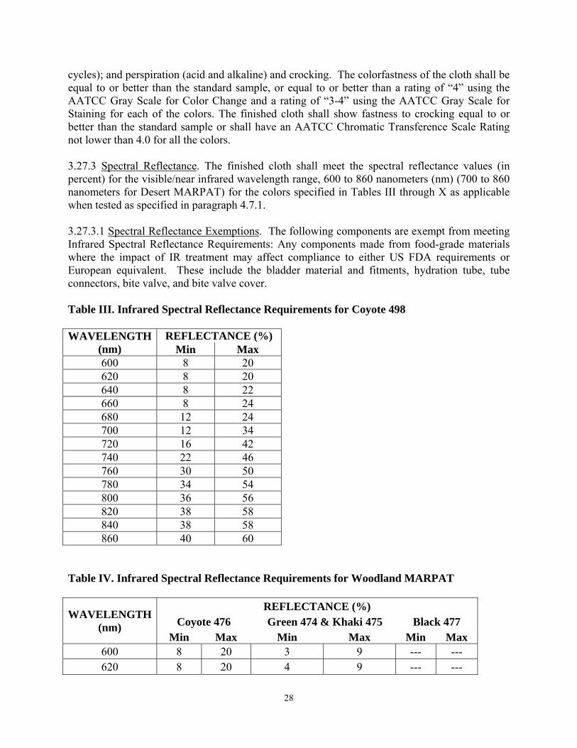
cycles); and perspiration (acid and alkaline) and crocking. The colorfastness of the cloth shall be equal to or better than the standard sample, or equal to or better than a rating of “4” using the AATCC Gray Scale for Color Change and a rating of “3-4” using the AATCC Gray Scale for Staining for each of the colors. The finished cloth shall show fastness to crocking equal to or better than the standard sample or shall have an AATCC Chromatic Transference Scale Rating not lower than 4.0 for all the colors. 3.27.3 Spectral Reflectance. The finished cloth shall meet the spectral reflectance values (in percent) for the visible/near infrared wavelength range, 600 to 860 nanometers (nm) (700 to 860 nanometers for Desert MARPAT) for the colors specified in Tables III through X as applicable when tested as specified in paragraph 4.7.1. 3.27.3.1 Spectral Reflectance Exemptions. The following components are exempt from meeting Infrared Spectral Reflectance Requirements: Any components made from food-grade materials where the impact of IR treatment may affect compliance to either US FDA requirements or European equivalent. These include the bladder material and fitments, hydration tube, tube connectors, bite valve, and bite valve cover. Table III. Infrared Spectral Reflectance Requirements for Coyote 498
WAVELENGTH
(nm) REFLECTANCE (%)
Min Max 600 8 20 620 8 20 640 8 22 660 8 24 680 12 24 700 12 34 720 16 42 740 22 46 760 30 50 780 34 54 800 36 56 820 38 58 840 38 58 860 40 60
Table IV. Infrared Spectral Reflectance Requirements for Woodland MARPAT
WAVELENGTH (nm)
REFLECTANCE (%) Coyote 476 Green 474 & Khaki 475 Black 477
Min Max Min Max Min Max 600 8 20 3 9 --- --- 620 8 20 4 9 --- ---
28

640 8 20 5 9 --- --- 660 8 20 6 12 --- --- 680 10 30 7 14 --- --- 700 18 50 8 28 --- 20 720 22 54 9 44 --- 30 740 30 56 10 52 --- 33 760 35 58 11 56 --- 33 780 40 62 12 56 --- 34 800 55 80 13 56 --- 34 820 55 80 14 60 --- 35 840 55 82 15 60 --- 35 860 60 82 16 60 --- 35
Table V. Infrared Spectral Reflectance Requirements for Snow MARPAT
WAVELENGTH (nm)
REFLECTANCE (%) White Snow
506 Light Snow Gray
507 Medium Snow Gray
508 Min Max Min Max Min Max
600 80 98 46 66 28 36 620 80 98 47 66 30 40 640 78 98 48 66 30 44 660 78 98 49 68 34 44 680 78 98 50 72 36 48 700 78 98 51 72 40 56 720 78 98 52 72 40 56 740 78 98 53 72 42 56 760 78 98 54 72 44 56 780 78 98 55 74 46 58 800 78 98 56 74 46 60 820 78 98 57 76 48 64 840 76 99 58 76 48 66 860 76 99 59 76 50 66
29
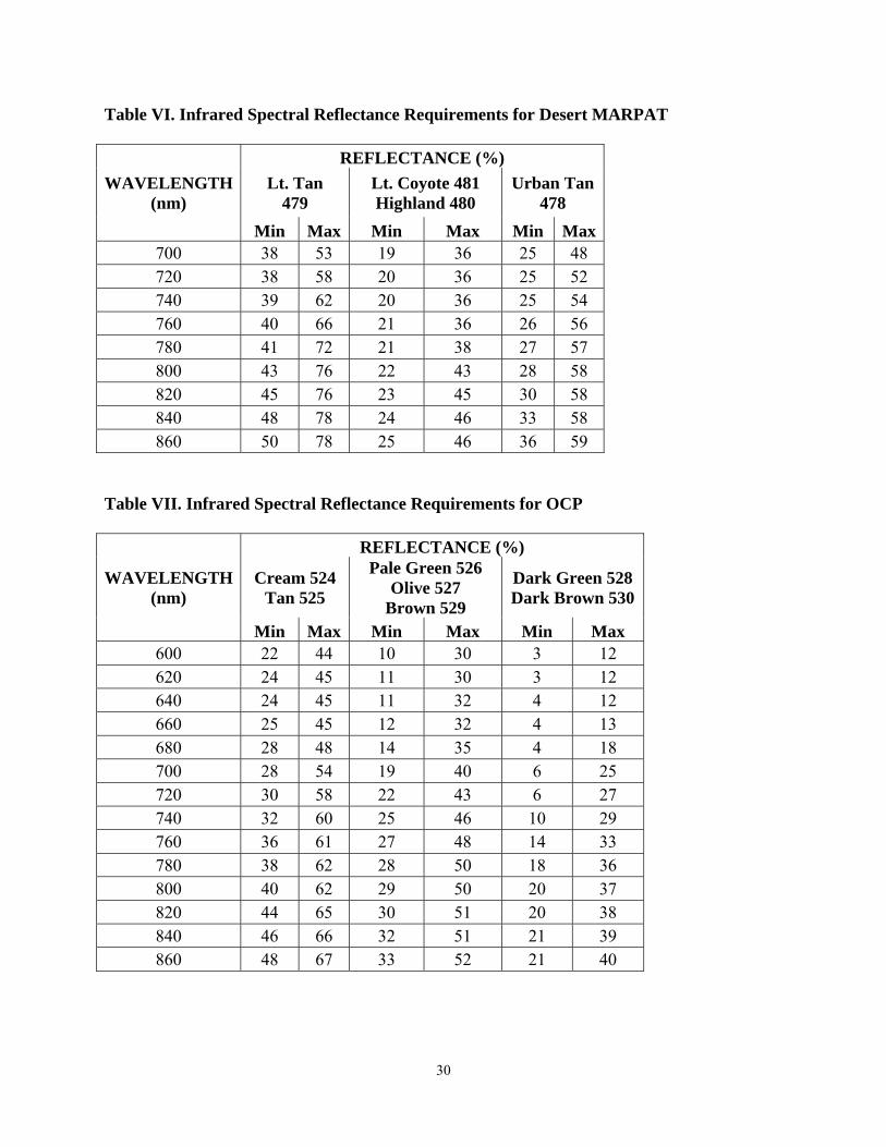
Table VI. Infrared Spectral Reflectance Requirements for Desert MARPAT
WAVELENGTH (nm)
REFLECTANCE (%) Lt. Tan
479 Lt. Coyote 481 Highland 480
Urban Tan 478
Min Max Min Max Min Max700 38 53 19 36 25 48 720 38 58 20 36 25 52 740 39 62 20 36 25 54 760 40 66 21 36 26 56 780 41 72 21 38 27 57 800 43 76 22 43 28 58 820 45 76 23 45 30 58 840 48 78 24 46 33 58 860 50 78 25 46 36 59
Table VII. Infrared Spectral Reflectance Requirements for OCP
WAVELENGTH (nm)
REFLECTANCE (%)
Cream 524 Tan 525
Pale Green 526 Olive 527
Brown 529
Dark Green 528 Dark Brown 530
Min Max Min Max Min Max 600 22 44 10 30 3 12 620 24 45 11 30 3 12 640 24 45 11 32 4 12 660 25 45 12 32 4 13 680 28 48 14 35 4 18 700 28 54 19 40 6 25 720 30 58 22 43 6 27 740 32 60 25 46 10 29 760 36 61 27 48 14 33 780 38 62 28 50 18 36 800 40 62 29 50 20 37 820 44 65 30 51 20 38 840 46 66 32 51 21 39 860 48 67 33 52 21 40
30

Table VIII. Infrared Spectral Reflectance Requirements for Foliage Green 504
WAVELENGTH (nm)
REFLECTANCE (%) Min Max
600 8 18 620 8 18 640 8 20 660 10 26 680 10 26 700 12 28 720 16 30 740 16 30 760 18 32 780 18 34 800 20 36 820 22 38 840 24 40 860 26 42
Table IX. Infrared Spectral Reflectance Requirements for Foliage Green 504 Acetal Hardware
WAVELENGTH (nm)
REFLECTANCE (%) Min Max
600 8 18 620 8 18 640 8 18 660 10 26 680 10 26 700 12 28 720 20 36 740 26 40 760 30 52 780 32 56 800 32 60 820 34 60 840 36 60 860 36 60
31

Table X. Infrared Spectral Reflectance Requirements for Black 357
WAVELENGTH (nm)
REFLECTANCE (%) Max
700 20 720 30 740 33 760 33 780 34 800 34 820 35 840 35 860 35
3.28 Interface requirements. The FILBE shall be compatible with the clothing and equipment commonly worn, carried and used by the individual Marine, to include body armor systems and ballistic helmets. All components of the system shall be compatible with each other. Integration of the components shall be accomplished with minimum use of straps/belts or hardware. 3.29 Pouch Attachment. The Pouch Attachment Ladder System (PALS) shall be used to attach modular pouches to the Chest Rig, Main Pack and Assault Pack. This system is a patented design and is not allowed for commercial sale without a license. There are no restrictions on the sale of this system under signed contracts with Federal agencies. 3.30 Performance. 3.30.1 Function. Components of FILBE, to include the USMC Pack, shall be easily and quickly donned and doffed. When in use, the entire system or individual components shall not impede proper head rotation of the user while standing or in a prone position, or carrying and shouldering of weapons in all firing positions. 3.30.2 Reliability. The components of the FILBE shall have a minimum service life of 360 operational hours of field use, unless otherwise specified. Additionally, the fabric used for the primary components shall be rot and mildew resistant and non-fabric parts of primary components shall be salt water-resistant. 3.30.3 Durability. 3.30.3.1 Durability, USMC Pack. The main pack with frame, hip-belt and shoulder harness, shall be capable of withstanding a Free Fall Drop test in accordance with paragraph 4.6.5.2 and an Airdrop Slide Impact test in accordance with paragraph 4.6.5.1. There shall be no rupture of seams or visual damage to the frame, fabric or components. Two separate items shall be used for the Free Fall Drop test and Airdrop Slide Impact test. Verification tests may be performed by the Government. 3.30.4 Environment. The FILBE will be used in all climatic categories during day and night
32

operations. Operation of all hardware components shall be easily operable when wearing heavy gloves, while operating during periods of darkness, and shall provide for a secure connection of the components. 4. VERIFICATION 4. 1 Classification of Inspections. The inspection requirements specified herein are classified as outlined below. Unless otherwise specified, the contractor is responsible for the performance of all inspection requirements specified herein. The Government reserves the right to perform any of the inspections set forth in this document where such inspections are deemed necessary to ensure the supplies conform to prescribed requirements.
a) First Article Test (see paragraph 4.2) b) Quality Conformance Inspection (see paragraph 4.3)
4.2 First Article Test. When a First Article Test is required, it shall be examined for design (paragraph 3.3), compatibility and interchangeability of components, inspection requirements (paragraph 4.5), data, certificate, or compliance for testing requirements (paragraphs 4.6 and 4.7), and overall workmanship. The procuring activity may waive any test(s) when sufficient documentation already exists to verify compliance. This is encouraged in cases when additional models, or minor changes from the currently approved model, are to be verified. In these cases, only the applicable portions of the First Article Test will be conducted. 4.2.1 Material Qualification. At any point after a First Article Test has been approved, any desired material change(s) must be submitted to the government via an Engineering Change Proposal (ECP) and shall be subject to testing in accordance with the appropriate paragraph of this Purchase Description. Changes to any material approved through First Article Testing must be approved in writing by the Government prior to presentation for inspection and acceptance. 4.3 Quality Conformance Inspection. Unless otherwise specified, at a minimum, the contractor’s quality plan shall be performed in accordance with ANSI/ASQC Z1.4 General Inspection Level II and an AQL of 2.5 for majors and an AQL of 4.0 for minors. The lot size shall be expressed in units of complete systems or individual components (when components are purchased separately). A sample unit shall be one system. Quality Conformance Inspection in accordance with paragraphs 4.3.1, 4.5, 4.6 4.3.1 Compatibility. The FILBE shall be examined to verify compatibility between components (attaching/detaching). 4.4 Certificate of Compliance (COC). COCs shall be provided when requested by the Government. The Government reserves the right to inspect any item to determine the validity of the certification.
4.5 Demonstration Verification. The performance requirement is verified by observation and operation that the properties, characteristics and parameters of the item meet the functional
33

requirements specified in applicable paragraphs of Section 3. Pass or fail criteria are simple accept or reject indications of functional performance since no qualitative values exist or are difficult to measure.
4.6 Requirements and Verifications. The following are performance requirements verified through visual methods, including physical measurements in order to determine that no deficiencies exist.
4.6.1 End Item Visual Inspection. The end items shall be inspected for the defects listed in Table XI and Table XII. The lot size shall be expressed in units of complete systems, or individual components (when components are purchased separately). A sample unit shall be one complete system or individual component. The number of sample units selected for sampling will be dictated by the inspection level. Table XI. End Item Visual Examination
CLASSIFICATION EXAMINE DEFECT MAJOR MINOR Fabric Hole, cut, tear, smash, broken or missing yarn, or
open place clearly visible at normal inspection distance (approximately 3 feet).
101
Shade bar or abrasion mark. 201 Defective or partially omitted coating 202 Webbing or Tape Any hole, cut, tears, or smash. 102 Not firmly and tightly woven, edges frayed or
scalloped. 103
Multiple floats 203 Abrasion mark, slub, or broken end or pick. 104 Cut ends of webbing not fused as specified. 105 Fastener Tape Any hole, cut, or tear. 106 Hooks flattened, broken, or missing. Impairing
function. 107
Hardware Broken or malformed, failing to serve intended purpose, corroded area, burr or sharp edge.
108
Finish omitted, not as specified, or area of partial or no finish.
110
Any required component improperly installed causing failure to serve intended purpose.
111
Not assembled as specified. 112 Size or type not as specified. 205 Snap fasteners
Any fastener not functioning properly. i.e. fails to snap closed, provide a secure closure, or to open freely.
NOTE: The fasteners shall be snapped and un-snapped twice to determine whether parts of fastener separate freely; and also affect a
113
34

secure closure. Clinched excessively tight, cutting adjacent
material. 114
Clinched loosely, permitting any component to rotate freely but not to the degree that any component can be expected to become detached during use.
206
Clinched loosely to the degree that components can be expected to become detached during use. NOTE: Incomplete roll of end of button or
eyelet barrel is evidence of improper and insecure clinching.
115
Incorrect style. 116 Any splits in eyelet or button barrels. 207 Drawstrings Cut, chafed, or abraded. 117 Ends not fused. 208 Not threaded through grommets or knotted as
specified. 209
Omitted. 118 Barrel lock Reversed. 210 Sub-assemblies Not attached as specified. 211 Brass grommets and eyelets
Clinched excessively tight, cutting adjacent material.
119
Insecurely clinched to a degree that grommet or eyelet may be detached from material.
120
Washer installed on incorrect side of material. 212 Eyelet barrel split. 213 Slide fastener
Not functioning properly, failing to effect a secure closure or to open freely.
121
Not specified type or size. 214 Slider jams or fails to interlock. 122 Thong omitted (if applicable). 123 Fastener tape cut or torn. 124 SEAMS AND STITCHING: Open seam 1/2 Inch or less. 215 More than 1/2 inch.
NOTE: A seam shall be classified as open when one or more stitches joining a seam are broken or when two or more consecutive skipped or run-off stitches occur. On double stitched seams, a seam shall be considered open when either one or both sides of the seam are open.
125
Raw edge (on edge required to be
More than 1/2 inch when securely caught in stitching.
216
35

finished) NOTE: Raw edge not securely caught in stitching shall be classified as an open seam.
Run-off (see open seam)
Seam and stitch type Wrong seam or stitch type. 126 Bartacks Any bartack omitted. 127 Any bartack not as specified or not in specified
location. 217
Loose stitching, incomplete or broken. 218 Stitch tension Loose, resulting in loose bobbin or top thread. 219 Excessively tight, resulting in puckering of
material. 220
Stitches per inch Up to two stitches less than minimum specified. 221 Three or more stitches less than minimum
specified. 128
One or more stitches in excess of maximum specified.
NOTE: Variation in the number of stitches per inch caused by the operator speeding up the machine and pulling the fabric in order to sew over heavy seams, or in turning corner shall be classified as follows:
(a) Within the minor defect classification no defect.
(b) Within the major defect classification minor defect.
222
Stitching ends Not secured as specified. 223 Thread breaks,
skipped stitches, or run-offs
Not overstitched as specified. NOTE: Thread breaks or two or more consecutive skipped or run-off stitches not overstitched shall be classified as open seams.
224
Rows of stitching Any row missing except on box, and box-x stitching.
129
On box, and box-x stitching: - one row of stitching omitted. - two or more rows of stitching omitted.
130
225
Component and assembly
Any component part omitted or not as specified or any operation omitted or not as specified (unless otherwise classified herein).
131
Needle chews. 132 Any mend, darn, patch, splice or other
unauthorized repair. 133
Any material pleated or caught in stitching where 226
36
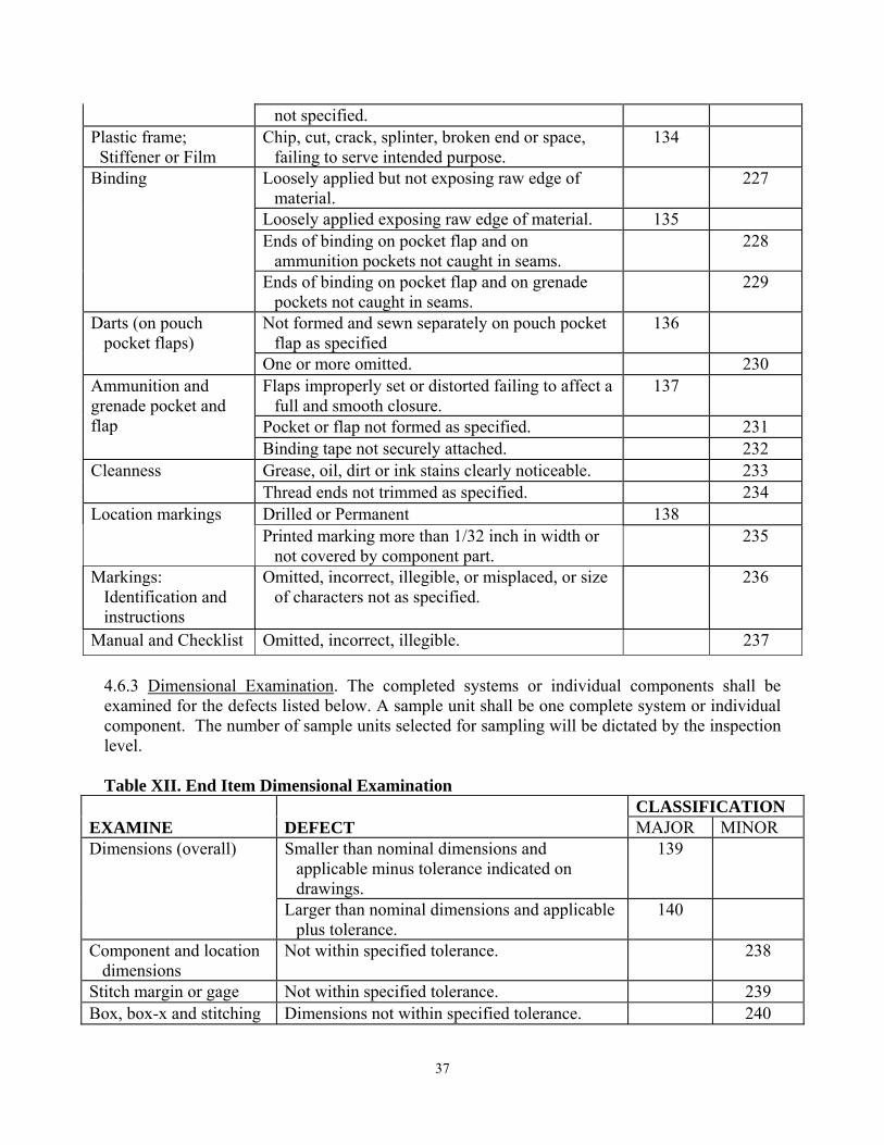
not specified. Plastic frame; Stiffener or Film
Chip, cut, crack, splinter, broken end or space, failing to serve intended purpose.
134
Binding Loosely applied but not exposing raw edge of material.
227
Loosely applied exposing raw edge of material. 135 Ends of binding on pocket flap and on
ammunition pockets not caught in seams. 228
Ends of binding on pocket flap and on grenade pockets not caught in seams.
229
Darts (on pouch pocket flaps)
Not formed and sewn separately on pouch pocket flap as specified
136
One or more omitted. 230 Ammunition and grenade pocket and flap
Flaps improperly set or distorted failing to affect a full and smooth closure.
137
Pocket or flap not formed as specified. 231 Binding tape not securely attached. 232
Cleanness Grease, oil, dirt or ink stains clearly noticeable. 233 Thread ends not trimmed as specified. 234 Location markings Drilled or Permanent 138 Printed marking more than 1/32 inch in width or
not covered by component part. 235
Markings: Identification and instructions
Omitted, incorrect, illegible, or misplaced, or size of characters not as specified.
236
Manual and Checklist Omitted, incorrect, illegible. 237 4.6.3 Dimensional Examination. The completed systems or individual components shall be examined for the defects listed below. A sample unit shall be one complete system or individual component. The number of sample units selected for sampling will be dictated by the inspection level. Table XII. End Item Dimensional Examination
CLASSIFICATION EXAMINE DEFECT MAJOR MINOR Dimensions (overall) Smaller than nominal dimensions and
applicable minus tolerance indicated on drawings.
139
Larger than nominal dimensions and applicable plus tolerance.
140
Component and location dimensions
Not within specified tolerance. 238
Stitch margin or gage Not within specified tolerance. 239 Box, box-x and stitching Dimensions not within specified tolerance. 240
37
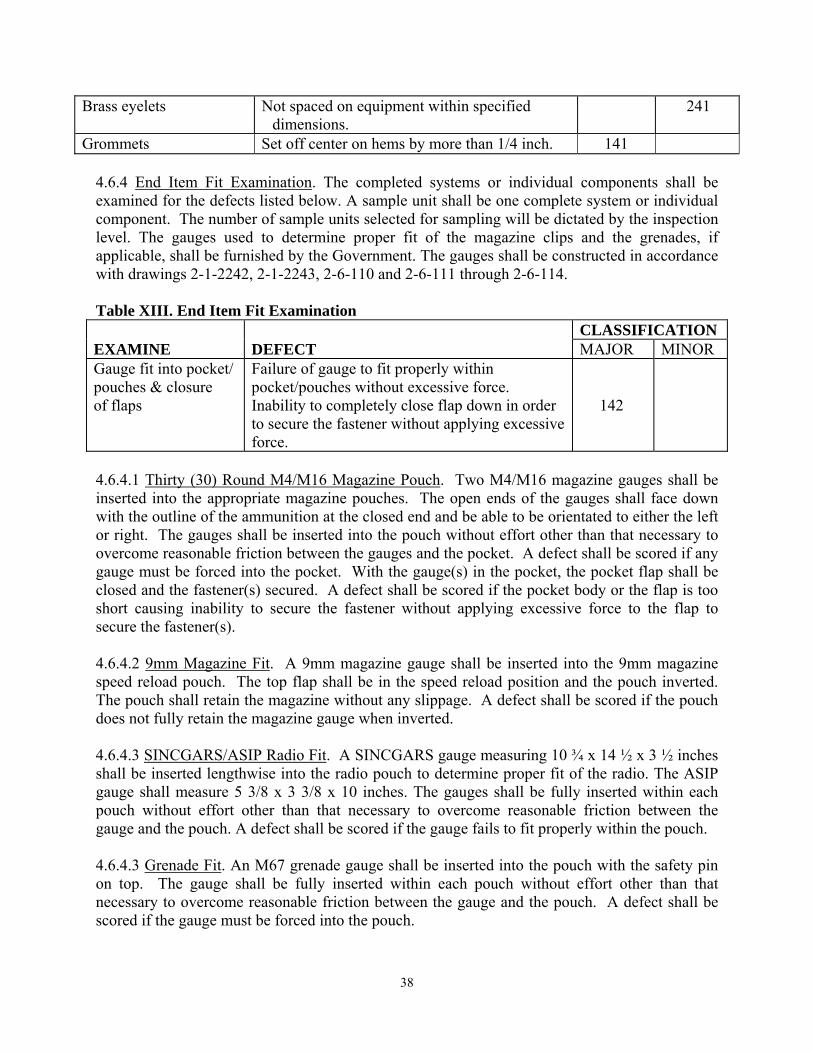
Brass eyelets Not spaced on equipment within specified dimensions.
241
Grommets Set off center on hems by more than 1/4 inch. 141 4.6.4 End Item Fit Examination. The completed systems or individual components shall be examined for the defects listed below. A sample unit shall be one complete system or individual component. The number of sample units selected for sampling will be dictated by the inspection level. The gauges used to determine proper fit of the magazine clips and the grenades, if applicable, shall be furnished by the Government. The gauges shall be constructed in accordance with drawings 2-1-2242, 2-1-2243, 2-6-110 and 2-6-111 through 2-6-114. Table XIII. End Item Fit Examination CLASSIFICATION EXAMINE DEFECT MAJOR MINOR Gauge fit into pocket/ pouches & closure of flaps
Failure of gauge to fit properly within pocket/pouches without excessive force. Inability to completely close flap down in order to secure the fastener without applying excessive force.
142
4.6.4.1 Thirty (30) Round M4/M16 Magazine Pouch. Two M4/M16 magazine gauges shall be inserted into the appropriate magazine pouches. The open ends of the gauges shall face down with the outline of the ammunition at the closed end and be able to be orientated to either the left or right. The gauges shall be inserted into the pouch without effort other than that necessary to overcome reasonable friction between the gauges and the pocket. A defect shall be scored if any gauge must be forced into the pocket. With the gauge(s) in the pocket, the pocket flap shall be closed and the fastener(s) secured. A defect shall be scored if the pocket body or the flap is too short causing inability to secure the fastener without applying excessive force to the flap to secure the fastener(s). 4.6.4.2 9mm Magazine Fit. A 9mm magazine gauge shall be inserted into the 9mm magazine speed reload pouch. The top flap shall be in the speed reload position and the pouch inverted. The pouch shall retain the magazine without any slippage. A defect shall be scored if the pouch does not fully retain the magazine gauge when inverted. 4.6.4.3 SINCGARS/ASIP Radio Fit. A SINCGARS gauge measuring 10 ¾ x 14 ½ x 3 ½ inches shall be inserted lengthwise into the radio pouch to determine proper fit of the radio. The ASIP gauge shall measure 5 3/8 x 3 3/8 x 10 inches. The gauges shall be fully inserted within each pouch without effort other than that necessary to overcome reasonable friction between the gauge and the pouch. A defect shall be scored if the gauge fails to fit properly within the pouch. 4.6.4.3 Grenade Fit. An M67 grenade gauge shall be inserted into the pouch with the safety pin on top. The gauge shall be fully inserted within each pouch without effort other than that necessary to overcome reasonable friction between the gauge and the pouch. A defect shall be scored if the gauge must be forced into the pouch.
38

4.6.4.4 Shotgun Shell Fit. A 12-gauge shotgun shell or dummy round shall be inserted into each of the elastic loops. Each shell or dummy round shall be cylindrical in shape measuring 51/64 ± 1/64 inches in diameter and 2 13/32 ± 1/32 inches long. The shall or dummy round must be fully inserted within each loop without effort other than that necessary to overcome reasonable friction between the shell or dummy round and the elastic webbing. The loaded panel shall be shaken three times in a sharp downward motion. If any shotgun shell or dummy rounds come loose, a defect shall be scored. 4.6.4.5 40mm High Explosive/Pyrotechnic Grenade Fit. The gauge shall be inserted into each high explosive grenade pouch. The flat ends of the fit gauges shall face towards the tab/flap of the pouch. A defect shall be scored if the gauge must be forced into the pouch. 4.6.4.6 Utility/Squad Automatic Pouch. A wooden gauge measuring 5 9/16 inch x 4 5/8 inch x 2 5/8 inch that represents a 100 round 7.62mm Linked Ammunition box shall be inserted lengthwise into the Utility/Squad Automatic pouch to determine proper fit. The gauge shall be fully inserted within each pocket without effort other than that necessary to overcome reasonable friction between the gauge and the pouch. A defect shall be scored if box fails to fit properly within the pouch. A wooden block 7 ¾ inch x 6 ½ inch x 3 1/8 inch representing a 200 round SAW drum shall be inserted lengthwise into the 200 round SAW drum pouch to determine proper fit. The gauge shall be fully inserted within each pouch without effort other than that necessary to overcome reasonable friction between the gauge and the pouch. A defect shall be scored if the drum fails to fit. 4.6.4.7 Ground Illumination Flare Single (Pop Up) Pouch. The pouch shall have a single closure device and securely contain one (1) ground illumination flare. The pouch shall contain the device with the cap facing up. 4.6.4.8 Thirty (30) Round M16/M4 Speed Reload Pouch Fit. The Speed Reload Pouch shall allow easy accessibility in order to provide the shooter his first choice for reloading. The magazine shall have adequate retention in the pouch without the use of a closure device and must be able to remain in the pouch without the use of the closure device during normal combat operations. The pouch shall have a single closure device that can be undone with one hand and shall not interfere with the quick reload capability. The pouch shall allow the magazine to be placed in the pouch with the rounds facing to either the left or right. 4.6.4.9 Magazine “Dump” Pouch. The pouch shall be able to contain eight (8) empty M16/M4 Magazines and have a closure device. The pouch shall be adjustable by two inches in the vertical direction and compatible with the martial arts belt and PALS webbing. 4.6.4.10 Multi-Grenade Pouch: Smoke/Riot/Thermite Grenade Pouch/Flash Bang. The pouch shall use a single closure device to keep the contents of the pouch secure until such time as the user desires. Neither the spoon nor safety pin shall protrude from the pouch. When not carrying a smoke grenade the pouch shall be able to hold at least one (1) flash bang. 4.6.5 End Item Testing.
39

4.6.5.1 Airdrop Slide Impact Test. The main pack with frame, hip-belt and shoulder harness shall be uniformly loaded with sand bags and cloth ballast to a capacity of 120 lbs. The loaded pack shall be slid down a wire at 45 degrees from vertical and reach a final velocity of 31 to 34 feet per second upon impacting the surface. The test shall be conducted three (3) times with impact on the frame and an additional three (3) times with impact on the main pack. Both slide impact tests shall be conducted on asphalt or concrete surfaces. There shall be no rupture of seams or visual damage to the frame, fabric or components. The sample unit shall be one frame and one main pack. 4.6.5.2 Free Fall Drop Test. The main pack with frame, hip-belt and shoulder harness shall be uniformly loaded with sand bags and cloth ballast to a capacity of 120 lbs. From a height of 10 feet, the loaded pack shall be dropped three (3) times with impact on the frame. The same item shall be dropped from a height of 10 feet an additional three (3) times with impact on the main pack. Both drop tests shall be conducted on asphalt or concrete surfaces. There shall be no rupture of seams or visual damage to the frame, fabric or components. The sample unit shall be one frame and one main pack. 4.6.6 Material Tests. The finished cloth and thread shall be tested for the characteristics listed in Table XIV. Table XIV. Material Tests
Characteristic Test MethodFabric Textured Nylon Weight ASTM D 3776 Breaking strength ASTM D 5034 Water repellency AATCC METHODS Colorfastness to: Laundering, after 3 cycles AATCC METHOD 61-1994 Laundering (accelerated black
print only) AATCC METHOD 61-1994
Light AATCC METHOD 16-1993 Crocking AATCC METHOD 8-1989 Resistance to frosting, for carbon
black AATCC METHOD 119 1/
Infrared reflectance Matching standard sample Visual Spray rating ATCC-22 Direct Transfer Hydrostatic resistance ATCC-127 Thread Breaking strength ASTM D 2207 Water repellency ASTM D 2207 2/ Webbing and Tape 1 inch webbing Weight ASTM D 3776 Breaking strength 3/
40

Fastness to: Laundering AATCC 61-1994 4/ Light AATCC 16-1993 5/ Crocking AATCC 8-1989 1 inch elastic webbing Weight ASTM D-3776 Load range 3/ Tension set 3/ Fastness to: Laundering AATCC 61-1994 4/ Light AATCC 16-1993 5/ Crocking AATCC 8-1989 1.5 inch webbing Weight ASTM D-3776 Breaking strength 3/ Fastness to: Laundering AATCC 61-1994 4/ Light AATCC 16-1993 5/ Crocking AATCC 8-1989 Spectral reflectance 2 inch webbing Weight ASTM D-3776 Breaking strength 3/ Fastness to: Laundering AATCC 61-1994 4/ Light AATCC 16-1993 5/ Crocking AATCC 8-1989 Spectral reflectance Tape, binding Weight ASTM D-3776 Breaking strength 3/ Fastness to: Laundering AATCC 61-1994 4/ Light AATCC 16-1993 5/
1) Except that the number of abrasion cycles shall be 300. 2) Single strand method. 3) As specified in contract. 4) Use Test 1A, Table I with the following changes: temperature = 100° + 40F, total liquid volume is 100 ml, time = 30 minutes. 5) Use option "A".
41
4.7 Method of Inspection.
4.7.1 Spectral Reflectance Measurements in the Visible/Near Infrared. Spectral reflectance data shall be obtained from 700 to 860 nanometers (nm) at 20 nm intervals for Desert MARPAT and 600 to 860 nanometers (nm) at 20 nm intervals for all other classes, on a spectrophotometer (see 6.3) relative to a barium sulfate standard, the preferred white reference standard. Other white reference materials may be used, provided they are calibrated to absolute white; e.g., Halon, magnesium oxide, or vitrolite tiles (see paragraph 6.4). Reflectance measurements may be made by either the monochromatic or polychromatic mode of operation. When the polychromatic mode is used, the spectrophotometer shall operate with the specimen diffusely illuminated with the full emission of a source that simulates either CIE Source A or CIE Source D65. Measurements will be taken on a minimum of two (2) different areas and the data averaged. The measured areas should be at least 6.0 inches away from the selvage. The specimen shall be measured as a single layer backed with layers of the same fabric and shade as follows: Class 1, Coyote 498, three (3) backing layers shall be used; Class 2, Woodland MARPAT, four (4) backing layers for Green 474, Khaki 475 and Coyote 476 and two (2) backing layers for Black 477; Class 3, Desert MARPAT, four (4) backing layers of the same shade; Class 4, Snow MARPAT, six (6) backing layers of the same shade; Class 5, Universal Camouflage Pattern, four (4) backing layers of the same shade. Loop fastener tape shall be measured as a single layer. The specimen shall be viewed at an angle not greater than 10 degrees from normal with the specular component included. Photometric accuracy of the spectrophotometer shall be within 1 percent and wavelength accuracy within 2.0 nm. The standard aperture size used in the color measurement device shall be 1.0 to 1.25 inches in diameter for Class 1 – Coyote 498 and 0.3725 inches or larger for Class 2 – Woodland MARPAT, Class 3 – Desert MARPAT, Class 4 – Snow MARPAT and Class 5 – Universal Camouflage Pattern. When the measured reflectance values for any color at four or more wavelengths do not meet the limits specified in Table III through X it shall be a test failure. 4.7.2 Determination of Fluorescence. One sample of cloth and one specimen from the standard sample shall be compared under ultraviolet light in an otherwise completely dark room. The specimen shall be considered satisfactory if its hue of fluorescence is the same as the standard sample. The result shall be reported as "pass" or "fail". 4.7.3 Verification Tests. Verification field tests may be conducted to verify requirements in Section 3 for which standard test methods are not available. The following requirements shall be verified:
A) Compatibility with clothing and equipment. B) Compatible with individual airborne equipment items and rigging
procedures. C) Individual components - Not impede head rotation while standing or in
prone position. D) Individual components - Not impede shouldering or firing weapons in all
firing position. E) Ease of attaching/detaching components. F) Secure connection of components to vest and frame. G) Durability of thread/stitching and fabric.
42

H) Easily field repairable. I) Carry varied combat loads through multiple mission profiles. J) Main pack and frame withstand Airdrop Slide Impact test (paragraph
4.6.5.1). K) Fit 5th percentile female Marine through the 95th percentile male Marine
population. 4.7.4 Thread Water Repellency Test. The finished treated thread shall be tested for water repellency in accordance with the vertical rise non-wicking procedure specified in paragraph 4.7.4.2 (initial) and the laundering procedure specified in paragraph 4.7.4.3 (after three launderings). The test apparatus shall be as specified in paragraph 4.7.4.1. 4.7.4.1 Test Apparatus. Test apparatus shall be as follows: Launder-Ometer. Launder-Ometer or similar machine in which tightly capped one-pint glass jars are held with their bases toward a horizontal shaft 2.0 inches from the center of rotation with the shaft rotating at a speed of 40 to 45 revolutions per minute (r.p.m.). The Launder-Ometer shall be maintained at a temperature of 160° + 2°F.
A) Detergent Solution. A 0.25 percent solution of sodium sulfate salt of oleyl methyl tauride (2.5 grams per liter).
B) Circulating Air Oven. A circulating air oven capable of maintaining a temperature of 221° to 230°F.
C) Twist Tester. A twist tester or other suitable device for twisting and cabling skeins. D) Water Tank. Vessel capable of holding a minimum 6.0 inch (152 mm) depth of
water. E) Laboratory Stand. Laboratory stand with movable crossbar rising 28 inches (711
mm) or more above the base. F) Weight. Weight, nonferrous, 3/4 to 7/8 ounce (21 g to 25 g). G) Dye. Dye-Basic Blue 9, color index 52015, salt and wetting agent free. H) Blotting Paper. The blotting paper shall be approximately 1.0 inch (25 mm) square. I) Yarn Reel. A 54 inch (1.37 mm) periphery skein reel or other suitable device for
preparing the specimen. J) Distilled Water. K) Paper Clip or Similar Clamp.
4.7.4.2 Non-Wicking Procedure (initial). The test specimen shall consist of twenty-strand skein of thread in one continuous 30 yard (27.4m) length made on a 54 inch (1.37m) periphery skein reel. The skein shall be reeled under enough tension to cause the strands in the skein to lie uniformly, side by side, on the reel. The finishing end of the skein shall be tied to the starting end of the skein in such a manner that the knot will not add additional length to the reel skein. The skein shall be hung over the crossbar of the laboratory stand with the other end hanging over the vessel. The weight shall be placed in the lower catenary of the skein to keep it taut and straight. The skein shall be arranged so that the strands are touching each other in flat ribbon form. The vessel shall be filled to a depth of at least 5.0 inches (127 mm) with distilled water at room temperature, which has been mixed with 0.05 percent dye. A piece of blotting paper shall
43

be attached by means of a paper clip or similar clamp to one full side (twenty strands) of the skein, 3.0 inches (76 mm) above the lower catenary of the skein. The position of the crossbar shall be so adjusted that when the skein is hung freely in the liquid, two inches of the skein will be immersed in the liquid and the lower edge of the blotter is 1.0 inch (25 mm) above the liquid surface. The skein shall then be slowly lowered into the dyebath and the time of entry shall be noted. Depending on the dimensions of the vessel and the length of the crossbar, several specimens can be tested at the same time in the same dye bath, by hanging the skeins sufficiently apart of the crossbar. The skein shall be exposed for 6 hours. The blotter shall be examined for wetting or staining at least once every hour. The test shall be terminated whenever staining or wetting of the blotter is observed, within the 6 hour test duration either in initial or laundered state. 4.7.4.3 Launder-Ometer Procedure. (Laundered). The thread shall be tested as specified in AATCC 61-1993 except as prepared below: The test specimen shall consist of a twenty-strand skein of thread in one continuous 30-yard length made on a 54-inch periphery skein reel. The skein shall be folded flat then twisted around its long axis for a total of 25 turns by use of a twist tester or other suitable device in the same direction as that of the final ply twist of the thread. The two ends shall be brought together and the folded skein allowed to back twist on itself. The ends shall be tied off to prevent untwisting during laundering. The specimen shall be placed in a 1 pint jar containing 100 ml of the 0.25 percent detergent solution at a temperature of 120° + 2°F. The jar shall then be sealed and agitated for 45 minutes at a temperature of 120° + 2°F in the Launder-Ometer at a speed of 40 to 45 rpm. At the end of the laundering period, the specimen shall be removed from the jar and rinsed thoroughly in running water at a temperature of 104° + 9°F and agitated occasionally during rinsing. Care should be exercised to insure that all traces of detergent are removed. The specimen shall then be extracted or wrung and oven dried at a temperature of 221° to 230° F until thoroughly dry. Repeat procedure two (2) more times, undo the tied ends from the skein, untwist skein and conduct procedure specified in paragraph 4.7.4.1 for laundered determination. 5. PACKAGING 5.1 Packaging. For acquisition purposes, the packaging requirements shall be as specified in the contract or order. 6. NOTES (This section contains information of a general or explanatory nature, which may be helpful, but is not mandatory). 6.1 Intended Use. The FILBE system is intended for use by Marines for man-transportation of mission essential items. 6.2 Standard Samples, Specifications/Drawings and Pattern Drawings. For access to the standard samples of finished fabrics, address the contracting activity issuing the invitation for bids or request for proposal.
44
45
6.3 Spectrophotometers. Suitable spectrophotometers for measuring spectral reflectance in the visible/near-infrared are the Diano Hardy, Diano Match Scan, Hunter D54-IR, Hunter VIS/NIR spectrocolorimeter and Macbeth 1500 with IR option. 6.4 Source of Material. Barium sulfate of suitable quality for use as white standard is available from Eastman Kodak Co. The same source has available magnesium reagent (ribbon) and Halo. Suitable tiles can be obtained from the National Bureau of Standards or from the instrument manufacturers. 6.5 Water Repellency. Approval of such compounds and combinations is the responsibility of the U.S. Army, Natick Soldier Center, Natick, MA 01760-5014, and is based on more extensive tests, including those for toxicity, which are not set forth in this document. Because of the time necessary to conduct full evaluation (approximately 6 months), only those chemical treatments already approved and so listed in the invitation for bids or request for proposal shall be considered acceptable for the related procurement.