pure sine wave bi-directional inverters manual - gb...
TRANSCRIPT

0
Microcare
Inverter
Manual

1
Contents
1. INTRODUCTION .......................................... 2
2. SAFETY INSTRUCTION .............................. 3
3. SYSTEM DESCRIPTION.............................. 6
4. INVERTER OPERATION .............................. 9
5. INVERTER PROGRAMMING ..................... 14
6. SPECIFICATIONS OF INVERTERS .......... 24

2
1. INTRODUCTION
1.1 General Description The Microcare Pure Sine Wave Inverter delivers clean true sine wave output power. Applicable for any kind of loads such as air-conditioners, home appliances, consumer electronics and office equipment. This series features a durable and continuous 24 hour operation. The compact and modular design makes utility interactive installations easier and more cost effective. It is a high quality product that offers the best price/performance ratio in the industry.
1.2 Key Features
1. Multiple microprocessor design base. 2. Compatible with both linear and non-linear load. 3. 24 hours operation on the inverter. 4. DC start and automatic self-diagnostic function. 5. THD less than 3%. 6. High Power 3 stage Charger 7. High efficiency design to save electricity. 8. Low heat dissipation in long time operation. 9. Design to operate under harsh environment. 10. Wall Mounted.
1.3 Important Notices • Read instructions carefully before operating Inverter.
• Inverter connection instructions must be followed.
• The unit should only be opened by skilled personal.
• Retain the load within in the rating of Inverter to prevent faults.
• Keep the Inverter clean and dry.
• If a 220vac supply is connected to the inverter and it is to be used as a UPS, then the inverter can only supply its rated power.

3
2. SAFETY INSTRUCTION
2.1 Positioning 1. Do not put the Inverter on rugged or inclined surface. 2. Do not install the Inverter near water or in damp environments. 3. Do not install the Inverter where it would be exposed to direct sunlight or near
heat. 4. Do not block off ventilation openings in the Inverter housing and don’t leave
objects on top of the Inverter. 5. Keep the Inverter far away from heat emitting sources. 6. Do not expose it to corrosive gas. 7. Ambient temperature: 0˚C - 40˚C.
2.2 Installation. MOUNT THE SINGLE HANGING BRACKET ONTO THE WALL. SLIDE THE INVERTER OVER THE BRACKET SO THE INVERTER HANGS FROM THE BRACKET.
1. Connect the Inverter AC OUTPUT only to an earthed DB Panel. 2. The AC connections are located at the top of the inverter under the top side
cover. (Where the Live and N In, Live and N Out and Earth Connections are.) 3. If a 220 vac supply or a generator is available connect into the Live In and
Neutral. 4. Make sure the BATTERY INPUT CIRCUIT BREAKER is OFF. 5. Place cables in such a way that no one can step on or trip over them. 6. Battery Cables must be a minimum size of 35mm² and short as possible. 7. The battery cables come out of the bottom of the unit next to the input circuit
breaker. 8. The unit must be mounted in a vertical position against the wall. 9. Designed to operate on a 48v battery system. 10. Minimum 300amp hour batteries to be used.
2.3 Earthing of Equipment. Equipment surge protection products are an effective way of controlling dangerous surges that can enter a facility. When strategically placed and correctly installed, the Surge Protectors will effectively reduce harmful over voltage conditions that can damage electrical and electronic equipment. It is important that the protection system includes both structural and surge protection equipment.
When lightning current passes into the ground through any conductor (Example: Tree Trunk) a powerful electromagnetic force is set up due to the fast rise times of the strike. This electromagnetic force then couples into any inductive loops that may be available in nearby buildings. When these currents equalize, damage usually occurs to the equipment.

4
1. LIVE IN and N IN – Connect to Grid 2. LIVE OUT and N OUT – Connect to AC Load. 3. EARTH 1 – Connect to Earth Bar. 4. EARTH 2 – Connect to Chassis Earth.
2.3.1 The Microcare inverter is designed primarily for Grid / Mains connection to
include charging. When Mains is connected to the inverter the Neutral connection is Earthed via the Mains.
If the Inverter is connected as a stand-alone inverter with no Mains Connection, The Neutral is required to be earthed using an earth spike.
If the Inverter is not earthed; warranty will be null and void.
2.3.2. INVERTER NEUTRAL CONNECTION
The inverter has a floating neutral so the neutral voltage will be close to 110v. In this case the live voltage with respect to the earth will also be around 110v.
5
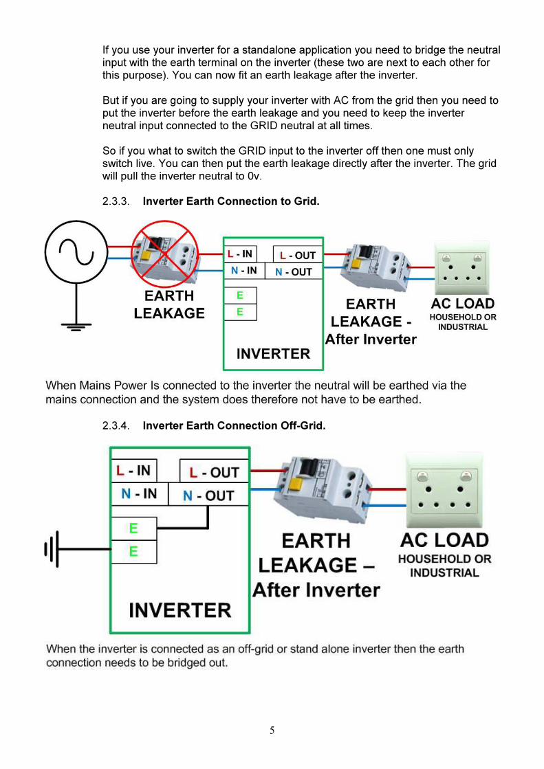
If you use your inverter for a standalone application you need to bridge the neutral input with the earth terminal on the inverter (these two are next to each other for this purpose). You can now fit an earth leakage after the inverter. But if you are going to supply your inverter with AC from the grid then you need to put the inverter before the earth leakage and you need to keep the inverter neutral input connected to the GRID neutral at all times. So if you what to switch the GRID input to the inverter off then one must only switch live. You can then put the earth leakage directly after the inverter. The grid will pull the inverter neutral to 0v. 2.3.3. Inverter Earth Connection to Grid.
2.3.4. Inverter Earth Connection Off-Grid.

6
2.4 Maintenance and Service
1. Caution – Risk of Electric Shock. 2. Batteries may cause electric shock and have a high short-circuit current. Please
take the precautionary measures specified below and any other measures necessary when working with batteries.
• Remove wristwatches, rings and other metal objects.
• Use only tools with insulated grips and handles.
3. SYSTEM DESCRIPTION
3.1 System Description. (1Kw;2Kw;3Kw and 5Kw Unit)
3.1.1 System Front View. (1Kw – 5Kw Unit)
3.1.2 System Back View. (1Kw – 5Kw Unit)

7
3.2 System Description. (10Kw and 12Kw) 3.2.1 System Front View. (10Kw – 12Kw Unit)
3.2.2 System Left View. (10Kw – 12Kw Unit)

8
3.2.3 System Right View. (10Kw – 12Kw Unit)
3.3 Front Panel Description for LCD Model.
3.3.1 LCD Display: This indicates the UPS’s operational information, including output voltage, battery voltage, output load and inside temperature.
3.3.2 UP–Key: Use to move the display up. 3.3.3 DOWN–Key: Use to move the display down. 3.3.4 ENTER–Key: It is pressed with the UP–Key to turn on the UPS. Push the ENTER
button to confirm or store DATA. 3.3.5 Push the UP and DOWN keys together to turn off the inverter. 3.3.6 Fault LED (Red): To indicate the INVERTER is in a fault condition because of
inverter shutdown or over temperature. 3.3.7 Warning LED (Yellow): To indicate the INVERTER is in the status of overload or
battery LOW. 3.3.8 Normal LED (Green): To indicate the INVERTER is operating normally.
3.4 Outline Description
Wall mount unit.
9
4. INVERTER OPERATION
4.0 Check Prior to Start Up
1. Ensure the INVERTER is mounted vertically. 2. Check input output cables are secured. 3. Check if Battery voltage meets the INVERTER rating required.
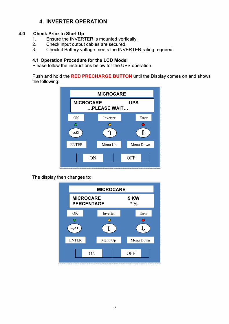
4.1 Operation Procedure for the LCD Model Please follow the instructions below for the UPS operation. Push and hold the RED PRECHARGE BUTTON until the Display comes on and shows the following:
The display then changes to:
MICROCARE 5 KW
PERCENTAGE * %
MICROCARE
ON OFF
ENTER Menu Down Menu Up
OK Inverter Error
MICROCARE UPS
…PLEASE WAIT…
MICROCARE
ON OFF
ENTER Menu Down Menu Up
OK Inverter Error

10
The display then changes to:
The display then changes to:
While holding in the PRECHARGE BUTTON turn on the MAIN CIRCUIT BREAKER.
UPS TURNED OFF
MICROCARE
ON OFF
ENTER Menu Down Menu Up
OK Inverter Error
UPS TURNED OFF
…CALIBRATING…
MICROCARE
ON OFF
ENTER Menu Down Menu Up
OK Inverter Error

11
1. By pressing the Enter-key and the UP-key simultaneously for 3 seconds, the UPS will start up and the OK LED lights up to indicate the power is from the inverter to the load and the MAINS / FAIL LED comes ON. The display will show:
2. By turning on a load the OUTPUT % will change to indicate the amount of LOAD as a % of the unit being used in KW.
3. When the Up-key and the Down-key are pressed simultaneously for 3 seconds, the
UPS will be turned OFF after two beeps. LCD DISPLAY MENU With the inverter in the ON position use the Up/Down keys to select menu-displays of the LCD described below. The screen will show the following: INV TURNED ON Push the OK button. Using the UP/Down Buttons the following screens can be seen.
This shows the power rating of the UPS and its % output.
Error
MICROCARE 5 KW
OUTPUT = INVERTER STANDBY
MICROCARE
ON OFF
ENTER Menu Down Menu Up
OK Inverter
Error
MICROCARE 5 KW
OUTPUT = INVERTER STANDBY
MICROCARE
ON OFF
ENTER Menu Down Menu Up
OK Inverter

12
Using the UP arrows the following details can be checked: This shows the battery voltage and the amps that the UPS is drawing from the battery.
This shows the output voltage and amps that the load is drawing from the Inverter.
This shows the internal temperature of the UPS.
TEMPERATURE
26.3 deg/cel
MICROCARE
ON OFF
ENTER Menu Down Menu Up
OK Inverter Error
UPS VOLTS : 220.0v
UPS AMPS : 0.0
MICROCARE
ON OFF
ENTER Menu Down Menu Up
OK Inverter Error
BATT VOLT : 54.0
BATT AMPS : 0.0
MICROCARE
ON OFF
ENTER Menu Down Menu Up
OK Inverter Error
13
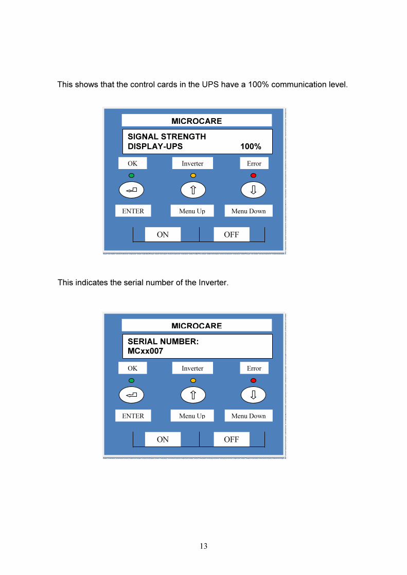
This shows that the control cards in the UPS have a 100% communication level.
This indicates the serial number of the Inverter.
SERIAL NUMBER: MCxx007
MICROCARE
ON OFF
ENTER Menu Down Menu Up
OK Inverter Error
SIGNAL STRENGTH
DISPLAY-UPS 100%
MICROCARE
ON OFF
ENTER Menu Down Menu Up
OK Inverter Error

14
5. INVERTER PROGRAMMING
There are two MENUS’ which allow the user to change either the SET UP or the BATTERY menus. Push the UP / DOWN keys to select which menu is to be changed.
Push ENTER if you want to change the set up menu.
By pushing ENTER you can change whether the inverter runs in SOLAR mode or MANUAL mode or only turns on if there is a load AUTO mode. In the AUTO mode the inverter uses the least amount of battery power when there is no load.
UPS MODE MANUAL SENSE
MICROCARE
ON OFF
ENTER Menu Down Menu Up
OK Inverter Error
ENTER SETUP MENU ?
MICROCARE
ON OFF
ENTER Menu Down Menu Up
OK Inverter Error

15
Push the ENTER button. The menu changes to:
Push the ENTER button. The menu changes to:
In order to run correctly in Solar Control Mode, the BATTERY OFF AT setup needs to be changed in the BATTERY SETUP MENU to: (2V – 48V; 1.5V – 36V; 1V – 24V; 0.5V – 12V) Less than the BATTERY RUN TO Value setup in the SETUP MENU.
When the inverter is running in solar control mode and the Charge level is set to LEVEL 1, the inverter will run the load using mains power and the solar regulator will charge the battery bank. The inverter will switch back over to battery power when the AC RUN TO Value is reached.
UPS MODE AUTO SENSE
MICROCARE
ON OFF
ENTER Menu Down Menu Up
OK Inverter Error
UPS MODE
SOLAR CONTROL
MICROCARE
ON OFF
ENTER Menu Down Menu Up
OK Inverter Error

16
Push the UP button in SOLAR mode you can then access the battery run to menu: (This allows the user to set the level the battery will go down to before switching to mains power.)
Battery Run To: 48v System – 46v (Default) (Can be changed in 2v Increments)
36v System – 34.5v (Default) (Can be changed in 1.5v Increments)
24v System – 23v (Default) (Can be changed in 1v Increments) 12v System – 11.5v (Default) (Can be changed in 0.5v Increments)
Push the ENTER button. The Menu settings can be changed.) Push the UP button. The menu changes to AC RUN TO menu: (Allows the user to set the level the mains will charge the battery to before the inverter switches back to battery power.)
AC Run To: 48v System – 54.4v (Default) (Can be changed in 2v Increments) 36v System – 40.5v (Default) (Can be changed in 1.5v Increments)
24v System – 24v (Default) (Can be changed in 1v Increments) 12v System – 12v (Default) (Can be changed in 0.5v Increments)
Push the ENTER button. The Menu settings can be changed.
SOLAR CONTROL AC RUN TO 54.4v
MICROCARE
ON OFF
ENTER Menu Down Menu Up
OK Inverter Error
SOLAR CONTROL BAT RUN TO 46.0v
MICROCARE
ON OFF
ENTER Menu Down Menu Up
OK Inverter Error

17
Push the UP button. The menu changes to:
This may be selected between LEVEL 1 which is the most sensitive to LEVEL 3 which is the least sensitive by pushing the ENTER button. To change the menu push the UP button.
The menu will then change to:
The sensitivity of the OVERLOAD TRIP may be changed thru 5 LEVELS. The factory default level is 2. Level 1 is HIGH and 2 is MEDIUM. These are instant trips. Levels 3 and 4 are HIGH and MEDIUM but have a 3 retry operation. If the inverter trips then it will try to restart using a soft start mode. LEVEL 5 is LOW. Push ENTER to select the mode.
LOAD MONITORING LEVEL (X) SELECTED
MICROCARE
ON OFF
ENTER Menu Down Menu Up
OK Inverter Error
MAINS MONITORING LEVEL 2 SELECTED
MICROCARE
ON OFF
ENTER Menu Down Menu Up
OK Inverter Error

18
Pushing the UP button will give you 3 options to SAVE the changed data. The display will show:
EXIT, DO NOT SAVE SET UP MENU ?
MICROCARE
ON OFF
ENTER Menu Down Menu Up
OK Inverter Error
RESTORE FACTORY
SET UP MENU ?
MICROCARE
ON OFF
ENTER Menu Down Menu Up
OK Inverter Error
EXIT AND SAVE
SET UP MENU ?
MICROCARE
ON OFF
ENTER Menu Down Menu Up
OK Inverter Error

19
If the changes to the settings need to be saved push ENTER if the enter button is pushed for any of the above then the unit will show:
If no entry is made for 1 minute the display will return to the main menu and the back light will turn off. Use the UP button to select BATTERY menu:
ENTER BATTERY MENU ?
MICROCARE
ON OFF
ENTER Menu Down Menu Up
OK Inverter Error
SAVING DATA TO INTERNAL MENU
MICROCARE
ON OFF
ENTER Menu Down Menu Up
OK Inverter Error

20
To change the BATTERY CHARGE menu push ENTER, the following will show:
This allows the user to program the charge rate from 0 to 100%. LEVEL 4 is the factory default. Level 1 is 0%, Level 2 is 5%, Level 3 is 25%, Level 4 is 50%, Level 5 is 75%, Level 6 is 100%.
INVERTER CHARGE AMPS
1Kw12V 40A
1Kw24V 30A
1Kw36V 20A
1Kw48V 10A
2Kw12V 80A
2Kw24V 40A
2Kw36V 30A
2Kw48V 20A
3Kw24V 60A
3Kw36V 40A
3Kw48V 30A
5Kw24V 100A
5Kw36V 75A
5Kw48V 50A
10Kw36V 100A
10Kw48V 100A
12Kw48V 100A
Above is the list of charge amps for all of the inverters. In regards to the battery charge level – The Level selected will allow the battery charge to the batteries. LEVEL 3 – 25% – On a 5Kw48V Inverter will allow a charge of 12.5A to the battery. LEVEL 5 – 75% – On a 5Kw48V Inverter will allow a charge of 37.5A to the battery.
BATTERY CHARGE
LEVEL (X) SELECTED
MICROCARE
ON OFF
ENTER Menu Down Menu Up
OK Inverter Error

21
Push the UP button. The menu changes to:
This allows the UPS to extract the maximum amount of power from a generator. The UPS constantly monitors the voltage from the generator and then applies maximum charge. LEVEL 1 is the lightest load to the generator while LEVEL 6 is the maximum. The factory default LEVEL is 1. This only needs to be adjusted if there is a generator connected. When a generator is running the generator will supply the AC Load first and the inverter will charge batteries with any excess power created from the generator.
AC INPUT MODE
LEVEL (X) SELECTED
MICROCARE
ON OFF
ENTER Menu Down Menu Up
OK Inverter Error

22
Push the UP button. The menu changes to:
By pushing ENTER this allows the user to adjust the BATTERY BOOST voltage. Push the UP key the next MENU is:
This allows the user to select the TIME that the BOOST VOLTAGE will be held at before changing to FLOAT. By pushing ENTER you can select 1, 2 or 3 hours.
BATTERY BST TIME BST FOR 1 HOUR
MICROCARE
ON OFF
ENTER Menu Down Menu Up
OK Inverter Error
Error
BATTERY BOOST BST = 57.2 VOLTS
MICROCARE
ON OFF
ENTER Menu Down Menu Up
OK Inverter

23
Push the UP button. The menu changes to:
This selects at what BATTERY LOW VOLTAGE the UPS will shut down. By pushing ENTER you can select to change the voltage.
Push the UP button. It is possible to FORCE the charger to go into another charge mode on a temporary basis. If the charger is in FLOAT but you require it to go back into BOOST then the next menu will allow this.
Pushing the ENTER button allows the charge to be changed from AUTO to BOOST or FLOAT. Push the UP button:
This will give you the options of saving the changes that have been made. Push ENTER at the correct SAVE menu.
BATTERY LOW OFF AT 40.0 VOLTS
MICROCARE
ON OFF
ENTER Menu Down Menu Up
OK Inverter Error
FORCE BAT INTO
AUTO CHARGE
MICROCARE
ON OFF
ENTER Menu Down Menu Up
OK Inverter Error

24
6. SPECIFICATIONS OF INVERTERS
MODEL 12/1000 MODEL 12/2000
Capacity Watt 1000 2000
Input
Nominal Voltage 12 Vdc 12 Vdc
Acceptable Voltage Range 10-15 Vdc 10-15 Vdc
Maxi Input Amps 100 200
Standby Power (manual mode) 15 watts 24 watts
Standby Power ( search mode) 8 watts 8 watts
Output
Voltage 220 Vac 220 Vac
Amps 5 amps 10 amps
Voltage Regulation < 3 % RMS for entire battery voltage
range < 3 % RMS for entire battery voltage
range
Frequency 50Hz 50Hz
Frequency Regulation ± 0.1Hz ± 0.1Hz
Power Factor 1 1
Wave Form Pure Sine Wave Pure Sine Wave
Efficiency 96% 96%
Circuit Breaker Circuit Breaker
Overload Protection Programmable Overload levels and
Auto Retry Programmable Overload levels and
Auto Retry
Charger
Float Voltage 13.8 13.8
Boost Voltage 13.8…….15.5 13.8…….15.5
Boost Time Selectable 1, 2, 3 hours. Selectable 1, 2, 3 hours.
Maximum Current 40 amps 80 amps
Generation Mode Depending on the generator power
available. Depending on the generator power
available.

25
MODEL 24/1000 MODEL 24/2000 MODEL 24/3000 MODEL 24/5000
Capacity Watt 1000 2000 3000 5000
Input
Nominal Voltage 24 Vdc 24 Vdc 24 Vdc 24 Vdc
Acceptable Voltage Range 20-30 Vdc 20-30 Vdc 20-30 Vdc 20-30 Vdc
Maxi Input Amps 55 75 150 250
Standby Power (manual mode) 20 watts 48 watts 48 watts
Standby Power ( search mode) 10 watts 15 watts 15 watts
Output
Voltage 220 Vac 220 Vac 220 Vac 220 Vac
Amps 5 amps 10 amps 14 amps 22 amps
Voltage Regulation < 3 % RMS for entire battery voltage range
< 3 % RMS for entire battery voltage range
< 3 % RMS for entire battery voltage range
< 3 % RMS for entire battery voltage range
Frequency 50Hz 50Hz 50Hz 50Hz
Frequency Regulation ± 0.1Hz ± 0.1Hz ± 0.1Hz ± 0.1Hz
Power Factor 1 1 1 1
Wave Form Pure Sine Wave Pure Sine Wave Pure Sine Wave Pure Sine Wave
Efficiency > 90 % 96% 96% > 90 %
Circuit Breaker Circuit Breaker Circuit Breaker Circuit Breaker
Overload Protection 110 % ~ 150 % for 30
Sec, > 150 % for 200ms
Programmable Overload levels and
Auto Retry
Programmable Overload levels and
Auto Retry
110 % ~ 150 % for 30 Sec, > 150 % for
200ms
Charger
Float Voltage 27.6 27.6 27.6 27.6
Boost Voltage 28.6……….31 27.6…….31 28.6…….31.0 28.6…….31.0
Boost Time Selectable 1, 2, 3
hours Selectable 1, 2, 3
hours. Selectable 1, 2, 3
hours. Selectable 1, 2, 3
hours.
Maximum Current 25 amps 40 amps 60 amps
Generation Mode Depending on the generator power
available.
Depending on the generator power
available
Depending on the generator power
available.
Depending on the generator power
available.

26
MODEL 36/5000 MODEL 36/10000
Capacity Watt 5000 10000
Input
Nominal Voltage 36 Vdc 36 Vdc
Acceptable Voltage Range 30-45 Vdc 30-45 Vdc
Maxi Input Amps 150 333 amps
Standby Power (manual mode) 60 watts 100 watts
Standby Power ( search mode) 20 watts 50 watts
Output
Voltage 220 Vac 220 Vac
Amps 22 amps 45 amps
Voltage Regulation < 3 % RMS for entire battery voltage
range < 3 % RMS for entire battery voltage
range
Frequency 50Hz 50Hz
Frequency Regulation ± 0.1Hz ± 0.1Hz
Power Factor 1 1
Wave Form Pure Sine Wave Pure Sine Wave
Efficiency 90% 92%
Circuit Breaker Circuit Breaker
Overload Protection 110 % ~ 150 % for 30 Sec, > 150 % for
200ms
Charger
Float Voltage 41.4 41.4
Boost Voltage 42.9…….46.5 42.9…….46.5
Boost Time Selectable 1, 2, 3 hours. Selectable 1, 2, 3 hours.
Maximum Current 70 amps 120 amps
Generation Mode Depending on the generator power
available. Depending on the generator power
available.

27
MODEL 48/1000 MODEL 48/2000 MODEL 48/3000
Capacity Watt 1000 2000 3000
Input
Nominal Voltage 48 Vdc 48 Vdc 48 Vdc
Acceptable Voltage Range 40-60 Vdc 40-60 Vdc 40-60 Vdc
Maxi Input Amps 25 75 75
Standby Power (manual mode)
30 watts 30 watts 48 watts
Standby Power ( search mode)
10 watts 10 watts 15 watts
Output
Voltage 220 Vac 220 Vac 220 Vac
Amps 5 amps 10 amps 14 amps
Voltage Regulation < 3 % RMS for entire battery voltage range
< 3 % RMS for entire battery voltage range
< 3 % RMS for entire battery voltage range
Frequency 50Hz 50Hz 50Hz
Frequency Regulation ± 0.1Hz ± 0.1Hz ± 0.1Hz
Power Factor 1 1 1
Wave Form Pure Sine Wave Pure Sine Wave Pure Sine Wave
Efficiency 96% 96% 96%
Circuit Breaker Circuit Breaker Circuit Breaker
Overload Protection Programmable Overload
levels and Auto Retry Programmable Overload
levels and Auto Retry Programmable Overload
levels and Auto Retry
Charger
Float Voltage 55.2 55.2 55.2
Boost Voltage 57.2V-62.0V 57.2V-62.0V 57.2V-62.0V
Boost Time Selectable 1, 2, 3 hours. Selectable 1, 2, 3 hours. Selectable 1, 2, 3 hours.
Maximum Current 10 amps 20 amps 30 amps
Generation Mode Depending on the
generator power available. Depending on the generator
power available. Depending on the
generator power available.

28
MODEL 48/5000 MODEL 48/10000 MODEL 48/12000
Capacity Watt 5000 10000 12000
Input
Nominal Voltage 48 Vdc 48V 48V
Acceptable Voltage Range 40-60 Vdc 40V-60V 40V-60V
Maxi Input Amps 125 250 Amps 300 Amps
Standby Power (manual mode)
60 watts 100 Watts 100 Watts
Standby Power ( search mode)
20 watts 50 Watts 50 Watts
Output
Voltage 220 Vac 220V 220V
Amps 22 amps 45 Amps 45 Amps
Voltage Regulation < 3 % RMS for entire battery
voltage range < 3 % RMS for entire battery voltage range
< 3 % RMS for entire battery voltage range
Frequency 50Hz 50 Hz 50 Hz
Frequency Regulation ± 0.1Hz ± 0.1 Hz ± 0.1 Hz
Power Factor 1 1 1
Wave Form Pure Sine Wave Pure Sine Wave Pure Sine Wave
Efficiency 90 % @ 90% Load 92% 92%
Circuit Breaker
Overload Protection Programmable Overload
levels and Auto Retry
Circuit Breaker / Programmable Overload
levels and Auto Retry
Circuit Breaker / Programmable Overload
levels and Auto Retry
Charger
Float Voltage 55.2 55.4V 55.4V
Boost Voltage 57.2V-62.0V 57.2V-62.0V 57.2V-62.0V
Boost Time Selectable 1, 2, 3 hours. Selectable 1, 2, 3 hours. Selectable 1, 2, 3 hours.
Maximum Current 50 amps 100 Amps 125 Amps
Generation Mode Depending on the generator
power available.
Depending on the generator power
available.
Depending on the generator power available.
29
J&J ELECTRONICS LIMITED WARRANTY
J&J Electronics warrants its full range of products against defects in workmanship and materials, fair wear and tear accepted, for a period of three (3) years from the date of delivery/collection for all equipment and are based on a bring-in-basis. Where the installation of the product makes it impractical to bring-in to our workshops, J&J Electronics reserves the right to charge for travel time and kilometres travelled to and from the site where the product is installed. During this warranty year period, J&J Electronics will, at its own discretion, repair or replace the defective product free of charge. This warranty will be considered void if the unit has suffered any physical damage or alteration, either internally or externally, and does not cover damages arising from improper use such as, but not exclusive to:
• Reverse of battery polarity.
• Inadequate or incorrect connection of the product and/or of its accessories.
• Mechanical shock or deformation. • Contact with liquid or oxidation by condensation.
• Use in an inappropriate environment (dust, corrosive vapour, humidity, high temperature, biological infestation).
• Breakage or damage due to lightning, surges, spikes or other electrical events.
• Connection terminals and screws destroyed or other damage such as overheating due to insufficient tightening of terminals.
• When considering any electronic breakage except due to lightning, reverse polarity, over-voltage, etc. the state of the internal control circuitry determines the warranty.
This warranty will not apply where the product has been misused, neglected, improperly installed, or repaired by anyone else than J&J Electronics or one of its authorised Qualified Service Partners. In order to qualify for the warranty, the product must not be disassembled or modified. Repair or replacement are our sole remedies and J&J Electronics shall not be liable for damages, whether direct, incidental, special, or consequential, even caused by negligence or fault. J&J Electronics owns all parts removed from repaired products. J&J Electronics uses new or re-conditioned parts made by various manufacturers in performing warranty repairs and building replacement products. If J&J Electronics repairs or replaces a part of a product, its warranty term is not extended. Removal of serial nos. may void the warranty. All remedies and the measure for damages are limited to the above. J&J Electronics shall in no event be liable for consequential, incidental, contingent or special damages, even if having been advised of the probability of such damages. Any and all other warranties expressed or implied arising by law, course of dealing, course of performance, usage of trade or otherwise, including but not limited to implied warranties of merchantability and fitness for a particular purpose, are limited in duration to a period of three (3) years from the date of purchase.

30
Life Support Policy: As a general policy, J&J Electronics does not recommend the use of any of its products in life support applications where failure or malfunction of the J&J Electronics product can be reasonably expected to cause failure of the life support device or to significantly affect its safety or effectiveness. J&J Electronics does not recommend the use of any of its products indirect patient care. J&J Electronics will not knowingly sell its products for use in such applications unless it receives in writing assurances satisfactory to J&J Electronics that the risks of injury or damage have been minimised, the customer assumes all such risks, and the Liability of J&J Electronics is adequately protected under the circumstances. Caution: Our products are sensitive. While all care is taken by us to dispatch goods with adequate packaging, J&J Electronics is not responsible for any damaged caused to products after they have left our premises. Semi-sealed batteries have to be transported upright and must not be put on their side. Please ensure that your transport company or delivery team is aware of the sensitivity of the products they are collecting. Goods return policy: The following terms apply to returns of items purchased from J&J Electronics, and we require the following information:
1. Details of the item(s) you would like to return. 2. Our invoice number. 3. The reason for the return. 4. J&J Electronics must be notified within 7 days of your intention to return the
goods which were purchased. 5. All items returned will be inspected prior to refund. If our technicians are not
immediately available, the goods will have to be left with us until such time as a technician is available to check the items.
6. Proof of purchase is required for all returns. 7. The price paid by the customers is the price on which the refund is based. 8. Items purchased can be returned for a refund, replacement or exchange,
provided proof of purchase is provided and subject to all other conditions as set down here.
9. All returns may be subject to an administration and handling fee of 10% of purchase price plus VAT.
10. Returns are based on a bring-in basis. 11. Returns will be refused in the following circumstances:
a. Where an item has been tampered with, altered or damaged in any way, or
b. Where a return is deemed unreasonable, this will be referred to management.
Severability: If a part of the terms and conditions set out above is held invalid, void, or unenforceable due to any particular national or international legislation, it shall not affect other parts of the terms and conditions remaining.
_______________________________________________________________