pure water series - village marinepw_3000_to_7000)_2012.pdf · pure water series pw 3,000-7,000 gpd...
TRANSCRIPT

Pure Water SeriesPW 3,000-7,000 GPD
Installation, Operation & Maintenance
Village Marine-PW 3000
Part Number: 95-0026

i
TABLE OF CONTENTS
1.0 SYSTEM DESCRIPTION 1
1.1 SPECIFICATIONS 1
1.1.1 PERFORMANCE CHARACTERISTICS 1
1.1.2 PHYSICAL CHARACTERISTICS 2
1.1.3 UTILITY REQUIREMENTS 2
1.1.4 ENVIRONMENTAL REQUIREMENTS 3
1.2 EQUIPMENT REQUIRED FOR OPERATION 3
1.2.1 CONSUMABLES 3
1.2.2 TEST EQUIPMENT 4
2.0 PREPARATION FOR USE, INSTALLATION AND INITIAL ADJUSTMENT 5
2.1 UNPACKING AND HANDLING 5
2.2 LOCATION 5
3.0 GENERAL THEORY OF OPERATION 9
3.1 REVERSE OSMOSIS THEORY 9
3.2 APPLICATION OF REVERSE OSMOSIS 10
3.3 PRODUCT WATER QUALITY STANDARDS 11
3.4 FACTORS AFFECTING PERMEATE PRODUCTION 11
3.4.1 VARIATIONS IN TEMPERATURE, PRESSURE AND SALINITY 11
3.4.2 TEMPERATURE CORRECTION FACTOR 12
3.5 OPERATIONAL DESCRIPTION 14
3.5.1 FILTRATION SYSTEM 14
3.5.2 REVERSE OSMOSIS SYSTEM 14
3.5.3 PRODUCT MONITORING SYSTEM 15
3.5.4 MEMBRANE CLEANING SYSTEM 15
3.6 WATER QUALITY MONITOR 16
3.6.1 PUSHBUTTONS 16
3.6.2 DISPLAYS AND LIGHTS 16
3.7 CONTROLS AND INSTRUMENTATION 16
ii
4.0 OPERATION 19
4.1 START-UP PROCEDURE 19
4.2 SHUTDOWN PROCEDURES 21
4.2.1 SHUTDOWN PROCEDURE (SHORT TERM) 21
4.2.2 SHUTDOWN PROCEDURE (EXTENDED) 22
4.3 FRESH WATER FLUSH PROCEDURE 22
5.0 MAINTENANCE INSTRUCTIONS 23
5.1 GENERAL 23
5.2 RAW WATER STRAINER INSPECTION 24
5.3 FILTER ELEMENT CLEANING OR REPLACEMENT 24
5.4 DRIVE BELT INSPECTION AND REPLACEMENT 25
5.5 RO MEMBRANE CLEANING 26
5.5.1 CLEANING CHEMICALS 26
5.5.2 WHEN TO CLEAN 27
5.6 RO ELEMENT PRESERVATION 30
5.7 RESTARTING UNIT AFTER PRESERVATION 31
5.8 HIGH PRESS7URE PUMP OIL CHANGE 31
5.9 HIGH PRESSURE PUMP MOTOR LUBRICATION 31
5.10 INSPECTION LOG 31
6.0 PRESSURE VESSELS AND MEMBRANES 34
6.1 PRESSURE VESSEL DISASSEMBLY 34
6.3 PRESSURE VESSEL ASSEMBLY 36
7.0 PRESERVATION FOR STORAGE 38
8.0 TROUBLESHOOTING 38
9.0 SYSTEM DRAWINGS AND DIAGRAMS / PARTS LIST 39
iii
LIST OF FIGURES
Figure 2.0 - Recommended Installation (Below Water Line) ............................................ 5
Figure 2.1 - Proper Installation (Above Water Line) ......................................................... 6
Figure 3.0 - Simple (Reverse) Osmotic System ............................................................... 9
Figure 3.1 - Simplified Schematic of an RO System....................................................... 10
Figure 5.0 - Maintenance Task Chart ............................................................................. 23
Figure 5.1 - Sample Operational Log ............................................................................. 32
Figure 5.2 - Sample Discrepancy Report ....................................................................... 33
Figure 6.0 - Pressure Vessel End Plug .......................................................................... 34
Figure 6.1 - Brine Seal Orientation ................................................................................. 35
Figure 6.2 - End Plug Installation Aid ............................................................................. 36
LIST OF TABLES
Table 1.0 - Performance Specification ............................................................................. 1
Table 1.1 - Unit Dimensions ............................................................................................. 2
Table 1.2 - Unit Weights................................................................................................... 2
Table 1.3 - HP Pump Horsepower.................................................................................... 2
Table 1.4 - Utility Requirements ....................................................................................... 2
Table 1.5 - Design Flow ................................................................................................... 3
Table 1.6 - Nominal Operating Conditions ....................................................................... 3
Table 1.7 - Consumables ................................................................................................. 4
Table 1.8 - Recommended Test Equipment..................................................................... 4
Table 3.0 - WHO Drinking Water Standards .................................................................. 11
Table 3.1 - Factors Affecting Permeate Quality.............................................................. 12
Table 3.2 - Temperature Correction Factors (TCF) ........................................................ 13
Table 3.3 - Instrumentation and Controls ....................................................................... 18
Table 4.0 - Valve/Switch Line Up - Initial Start-up .......................................................... 19
Table 5.0 - Filter Tank Parts List. ................................................................................... 24
Table 5.1 - Chemical Requirements ............................................................................... 26
Table 5.2 - Lubrication Requirements ............................................................................ 31
iv
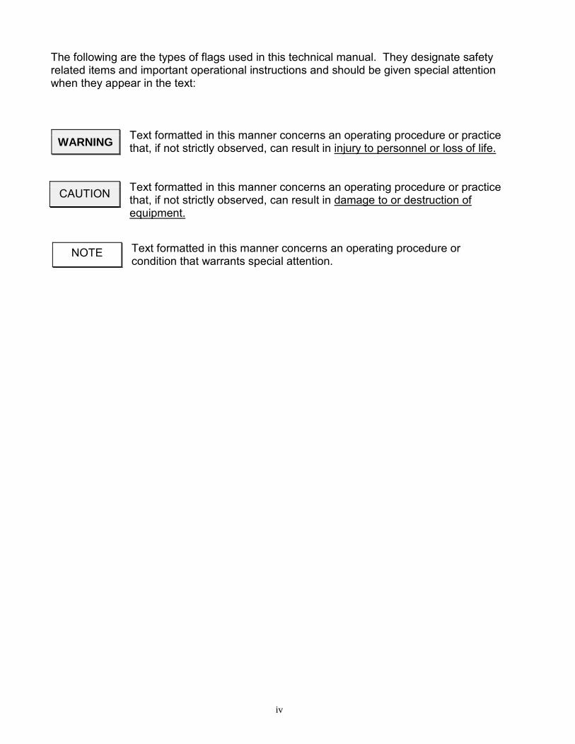
The following are the types of flags used in this technical manual. They designate safetyrelated items and important operational instructions and should be given special attentionwhen they appear in the text:
Text formatted in this manner concerns an operating procedure or practicethat, if not strictly observed, can result in injury to personnel or loss of life.
Text formatted in this manner concerns an operating procedure or practicethat, if not strictly observed, can result in damage to or destruction ofequipment.
Text formatted in this manner concerns an operating procedure orcondition that warrants special attention.
WARNING
CAUTION
NOTE
PW-3000 to PW-20000 Manual 1 Last Revised 01/12
1.0 SYSTEM DESCRIPTION
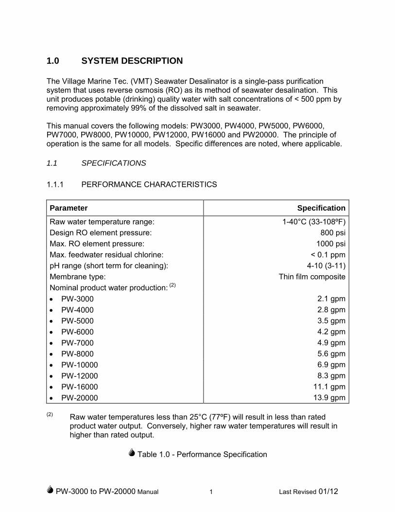
The Village Marine Tec. (VMT) Seawater Desalinator is a single-pass purificationsystem that uses reverse osmosis (RO) as its method of seawater desalination. Thisunit produces potable (drinking) quality water with salt concentrations of < 500 ppm byremoving approximately 99% of the dissolved salt in seawater.
This manual covers the following models: PW3000, PW4000, PW5000, PW6000,PW7000, PW8000, PW10000, PW12000, PW16000 and PW20000. The principle ofoperation is the same for all models. Specific differences are noted, where applicable.
1.1 SPECIFICATIONS
1.1.1 PERFORMANCE CHARACTERISTICS
Parameter Specification
Raw water temperature range: 1-40°C (33-108ºF)
Design RO element pressure: 800 psi
Max. RO element pressure: 1000 psi
Max. feedwater residual chlorine: < 0.1 ppm
pH range (short term for cleaning): 4-10 (3-11)
Membrane type: Thin film composite
Nominal product water production: (2)
PW-3000 2.1 gpm
PW-4000 2.8 gpm
PW-5000 3.5 gpm
PW-6000 4.2 gpm
PW-7000 4.9 gpm
PW-8000 5.6 gpm
PW-10000 6.9 gpm
PW-12000 8.3 gpm
PW-16000 11.1 gpm
PW-20000 13.9 gpm
(2) Raw water temperatures less than 25°C (77ºF) will result in less than ratedproduct water output. Conversely, higher raw water temperatures will result inhigher than rated output.
Table 1.0 - Performance Specification

PW-3000 to PW-20000 Manual 2 Last Revised 01/12
1.1.2 PHYSICAL CHARACTERISTICS
PW3000-5000
PW6000PW7000-
12000PW16000-
20000
Length 84" 84" 84" 84”
Width 34" 44" 48" 52”
Height 35" 35" 35" 43”
Table 1.1 - Unit Dimensions
PW3000 PW4000 PW5000 PW6000 PW7000
Weight 800 LB 900 LB 1000 LB 1050 LB 1500 LB
PW8000 PW10000 PW12000 PW16000 PW20000
Weight 1600 LB 1800 LB 1900 LB 2200 LB 2250 LB
Table 1.2 – Unit Weights
1.1.3 UTILITY REQUIREMENTS
See the nameplate attached to top of the unit for power requirements.
PW3000 PW4000 PW5000 PW6000 PW7000
Motor HP 10 10 15 15 15
PW8000 PW10000 PW12000 PW16000 PW20000
Motor HP 20 20 25 25 30
Table 1.3 – HP Pump Horsepower
Utility ConnectionDesign Pressure
Minimum(psi)
Design PressureMaximum
(psi)
Raw water inlet 1 ½” ANSI Flange 0 50
Reject discharge* 1 ½” ANSI Flange 0 15
Product water discharge 1” ANSI Flange 0 15
Flush water inlet 1 ½” NPT 20 50
* Vacuum condition at shutdown is not acceptable, syphon breaker may be reqd.
Table 1.4 - Utility Requirements
PW-3000 to PW-20000 Manual 3 Last Revised 01/12
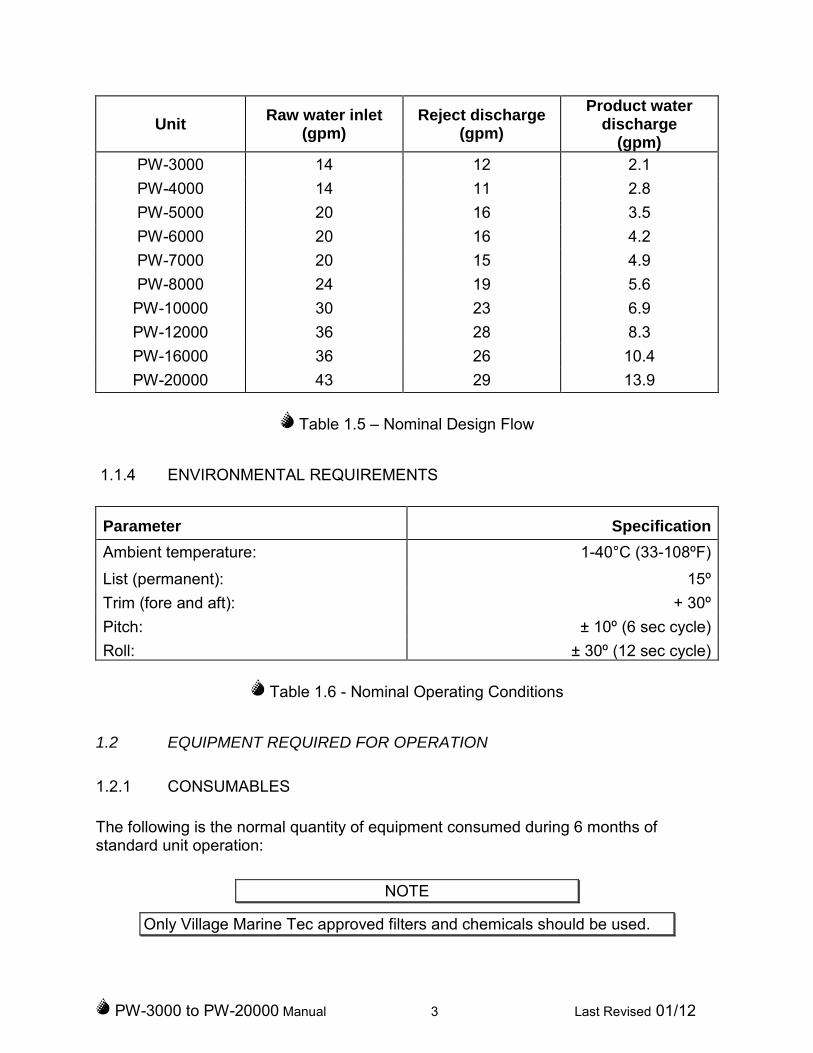
UnitRaw water inlet
(gpm)Reject discharge
(gpm)
Product waterdischarge
(gpm)
PW-3000 14 12 2.1
PW-4000 14 11 2.8
PW-5000 20 16 3.5
PW-6000 20 16 4.2
PW-7000 20 15 4.9
PW-8000 24 19 5.6
PW-10000 30 23 6.9
PW-12000 36 28 8.3
PW-16000 36 26 10.4
PW-20000 43 29 13.9
Table 1.5 – Nominal Design Flow
1.1.4 ENVIRONMENTAL REQUIREMENTS
Parameter Specification
Ambient temperature: 1-40°C (33-108ºF)
List (permanent): 15º
Trim (fore and aft): + 30º
Pitch: ± 10º (6 sec cycle)
Roll: ± 30º (12 sec cycle)
Table 1.6 - Nominal Operating Conditions
1.2 EQUIPMENT REQUIRED FOR OPERATION
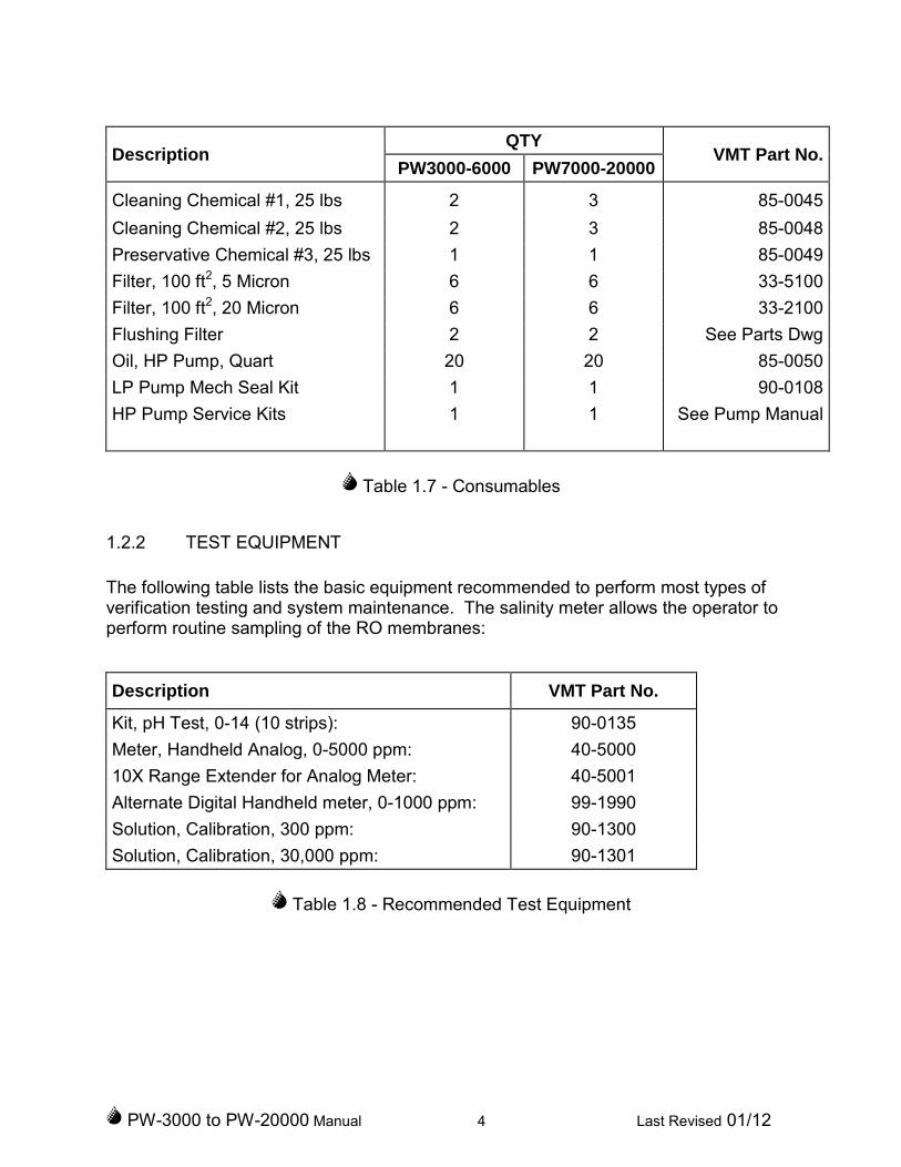
1.2.1 CONSUMABLES
The following is the normal quantity of equipment consumed during 6 months ofstandard unit operation:
NOTE
Only Village Marine Tec approved filters and chemicals should be used.
PW-3000 to PW-20000 Manual 4 Last Revised 01/12
DescriptionQTY
VMT Part No.PW3000-6000 PW7000-20000
Cleaning Chemical #1, 25 lbs 2 3 85-0045
Cleaning Chemical #2, 25 lbs 2 3 85-0048
Preservative Chemical #3, 25 lbs 1 1 85-0049
Filter, 100 ft2, 5 Micron 6 6 33-5100
Filter, 100 ft2, 20 Micron 6 6 33-2100
Flushing Filter 2 2 See Parts Dwg
Oil, HP Pump, Quart 20 20 85-0050
LP Pump Mech Seal Kit 1 1 90-0108
HP Pump Service Kits 1 1 See Pump Manual
Table 1.7 - Consumables
1.2.2 TEST EQUIPMENT
The following table lists the basic equipment recommended to perform most types ofverification testing and system maintenance. The salinity meter allows the operator toperform routine sampling of the RO membranes:
Description VMT Part No.
Kit, pH Test, 0-14 (10 strips): 90-0135
Meter, Handheld Analog, 0-5000 ppm: 40-5000
10X Range Extender for Analog Meter: 40-5001
Alternate Digital Handheld meter, 0-1000 ppm: 99-1990
Solution, Calibration, 300 ppm: 90-1300
Solution, Calibration, 30,000 ppm: 90-1301
Table 1.8 - Recommended Test Equipment
PW-3000 to PW-20000 Manual 5 Last Revised 01/12
2.0 PREPARATION FOR USE, INSTALLATION AND INITIAL
ADJUSTMENT
2.1 UNPACKING AND HANDLING
Remove unit from shipping crate and inspect for shipping damage.
CAUTION
Do not allow unit or any components to be exposed to freezingtemperatures. If it is anticipated that the unit may be exposed to freezing
temperature, please contact VMT in advance for technical assistance.
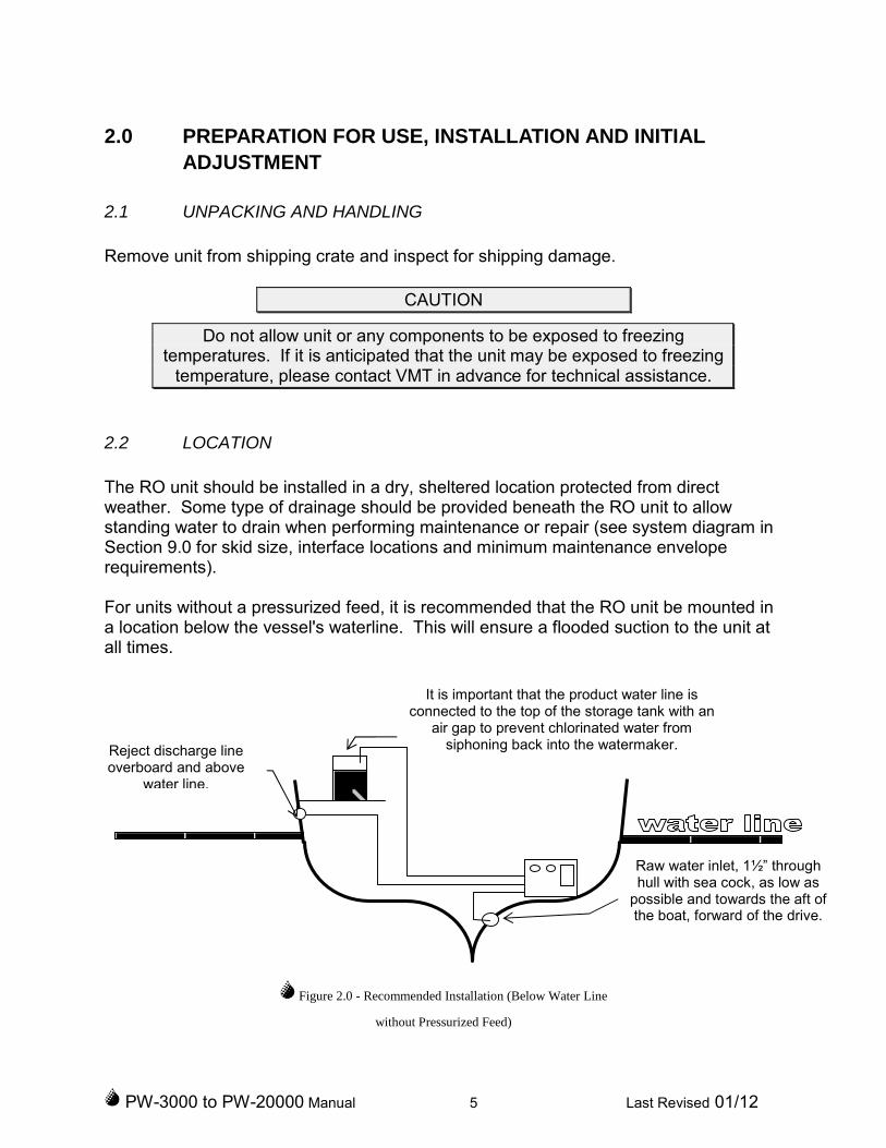
2.2 LOCATION
The RO unit should be installed in a dry, sheltered location protected from directweather. Some type of drainage should be provided beneath the RO unit to allowstanding water to drain when performing maintenance or repair (see system diagram inSection 9.0 for skid size, interface locations and minimum maintenance enveloperequirements).
For units without a pressurized feed, it is recommended that the RO unit be mounted ina location below the vessel's waterline. This will ensure a flooded suction to the unit atall times.
Figure 2.0 - Recommended Installation (Below Water Line
without Pressurized Feed)
It is important that the product water line isconnected to the top of the storage tank with an
air gap to prevent chlorinated water fromsiphoning back into the watermaker.
Raw water inlet, 1½” throughhull with sea cock, as low as
possible and towards the aft ofthe boat, forward of the drive.
Reject discharge lineoverboard and above
water line.

PW-3000 to PW-20000 Manual 6 Last Revised 01/12
If it is not possible to mount the watermaker below the water line, the boost pump canlift to a maximum height of 15 feet (5 feet for 50 Hz units) above the water line with theboost pump removed from the frame and installed below the RO frame near the throughhull. A check valve might be required in the suction line to maintain adequate systempriming. Locating the system any more than 15 feet above the water line requiresinstallation of external pumps to maintain a pressurized feed.
Figure 2.1 - Proper Installation
(Above Water Line)
Since every installation is unique, the mounting instructions are provided for guidanceonly. It is recommended that you use your own discretion as to the exact method ofmounting and placement of any mounting bolts.
1) Place the RO unit in an appropriate location and use existing holes or drill newholes for a minimum of four point mounting by studs or bolts. Mount the RO unitsecurely making sure that the base of the unit is continuously supported.
2) Make the following plumbing connections to the RO unit's piping interfaces (referto Section 9.0 for the exact piping interface locations):
a) Connect the raw water supply (1½" flange connection inlet) to a cleanseawater source.
CAUTION
Raw water inlet, 1-1/2” throughhull with sea cock, low as possible
and towards theAft of the vessel, forward of the
drive.
Reject dischargeline overboard andabove water line.
It is important that the product water line isconnected to the top of the storage tank to prevent
chlorinated water from siphoning back into thewatermaker.
Boost pump below water linewith flooded suction.
PW-3000 to PW-20000 Manual 7 Last Revised 01/12
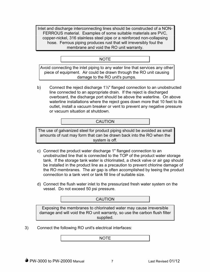
Inlet and discharge interconnecting lines should be constructed of a NON-FERROUS material. Examples of some suitable materials are PVC,copper-nickel, 316 stainless steel pipe or a reinforced non-collapsing
hose. Ferrous piping produces rust that will irreversibly foul themembrane and void the RO unit warranty.
NOTE
Avoid connecting the inlet piping to any water line that services any otherpiece of equipment. Air could be drawn through the RO unit causing
damage to the RO unit's pumps.
b) Connect the reject discharge 1½" flanged connection to an unobstructedline connected to an appropriate drain. If the reject is dischargedoverboard, the discharge port should be above the waterline. On abovewaterline installations where the reject goes down more that 10 feet to itsoutlet, install a vacuum breaker or vent to prevent any negative pressureor vacuum situation at shutdown.
CAUTION
The use of galvanized steel for product piping should be avoided as smallamounts of rust may form that can be drawn back into the RO when the
system is off.
c) Connect the product water discharge 1" flanged connection to anunobstructed line that is connected to the TOP of the product water storagetank. If the storage tank water is chlorinated, a check valve or air gap shouldbe installed in the product line as a precaution to prevent chlorine damage ofthe RO membranes. The air gap is often accomplished by teeing the productconnection to a tank vent or tank fill line of suitable size.
d) Connect the flush water inlet to the pressurized fresh water system on thevessel. Do not exceed 50 psi pressure.
CAUTION
Exposing the membranes to chlorinated water may cause irreversibledamage and will void the RO unit warranty, so use the carbon flush filter
supplied.
3) Connect the following RO unit's electrical interfaces:
NOTE

PW-3000 to PW-20000 Manual 8 Last Revised 01/12
Strictly observe all applicable electrical codes and regulations governingthe installation and wiring of electrical equipment. Typical codes specifythe type and size of conduit, wire diameter and class of wire insulationdepending upon the amperage and environment. The power supply
should always be of a greater service rating than the requirements of theRO unit. This will assure proper voltage even if power supply voltage is
slightly less than required. Never connect the RO unit to a line thatservices another electrical device. The RO unit should have its own
dedicated power supply and breaker.
WARNING
Disconnect electrical power to RO unit and the power source beforeconnecting to RO unit interface. Failure to do so can cause serious
injury or death to personnel.
a) Connect the correct voltage/power supply to the three-phase or single phasesupply point in the Motor Starter Box. Correct high pressure pump rotation isclockwise when viewing the motor fan (or counter-clockwise when viewingfrom the shaft and pulley end. Correct rotation for the low pressure boostpump is clockwise when viewing the motor fan.
IMPORTANT NOTE
Three phase power supplies will spin the motors and pumps eitherrotation direction, depending on the phase sequence of the three hotpower legs. It is very important not to rotate the low pressure pumpbackwards. Even “bumping” the motor for one second can cause
significant damage. The high pressure pump will not be damaged fromrunning backwards. Either use a phase meter to determine the rotation,
or use the high pressure pump only to check rotation and adjust theinput power legs accordingly prior to checking the low pressure pump. Ifthe low pressure pump is inadvertently “bumped” backwards, open thepump and check the impellor is secured on the motor shaft and spins
freely prior to starting it again.
b) Connect a suitable ground to the RO unit skid (as determined by thespecifics of your installation).

PW-3000 to PW-20000 Manual 9 Last Revised 01/12
3.0 GENERAL THEORY OF OPERATION
3.1 REVERSE OSMOSIS THEORY
Reverse osmosis, like many other practical scientific methods, has been developedfrom processes first observed in nature. Osmosis is a naturally occurring phenomenonin which a semi-permeable membrane separates a pure and a concentrated solution (asemi-permeable membrane is defined as one that preferentially passes a particularsubstance). Every fluid has an inherent potential that is directly related to the type andamount of solids in solution. This potential, referred to as osmotic pressure, increasesin proportion to relative concentration of a solution. A concentrated solution, therefore,has an osmotic pressure that is higher than that of a pure solution.
In an osmotic system, the less concentrated solution will attempt to equalize theconcentrations of both solutions by migrating across the semi-permeable membrane.When enough pure solution migrates across the membrane such that the inherentpotential difference between the solutions is no longer higher than the osmotic pressureof the membrane, the purer solution will stop flowing. If the pressure on theconcentrated solution is increased to above the osmotic pressure, fluid flow will bereversed. This condition, called Reverse Osmosis, can be established by artificiallypressurizing the more concentrated solution using a high pressure pump. In this type ofsystem, the concentrated solution (normally referred to as feedwater) will become moreconcentrated as pure water flows out of solution and across the membrane to thepermeate side. Discounting the effects of feedwater temperature and salinity, theoperating pressure normally required to produce significant amounts of pure water is atleast twice the osmotic pressure of the membrane being used.
SALINE
SOLUTION
PURE
SOLUTION
SEMI-PERMEABLE MEMBRANE
ATMOSPHERIC
PRESSURE
(14.7 PSI)
SALINE
SOLUTION
PURE
SOLUTION
HIGH
PRESSURE
(800 PSI)
OSMOSIS REVERSE OSMOSIS
Figure 3.0 - Simple (Reverse) Osmotic System
PW-3000 to PW-20000 Manual 10 Last Revised 01/12
3.2 APPLICATION OF REVERSE OSMOSIS
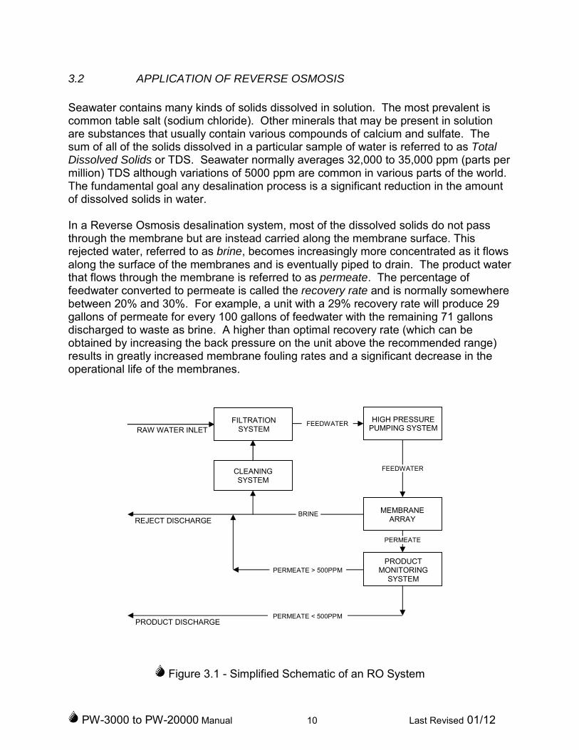
Seawater contains many kinds of solids dissolved in solution. The most prevalent iscommon table salt (sodium chloride). Other minerals that may be present in solutionare substances that usually contain various compounds of calcium and sulfate. Thesum of all of the solids dissolved in a particular sample of water is referred to as TotalDissolved Solids or TDS. Seawater normally averages 32,000 to 35,000 ppm (parts permillion) TDS although variations of 5000 ppm are common in various parts of the world.The fundamental goal any desalination process is a significant reduction in the amountof dissolved solids in water.
In a Reverse Osmosis desalination system, most of the dissolved solids do not passthrough the membrane but are instead carried along the membrane surface. Thisrejected water, referred to as brine, becomes increasingly more concentrated as it flowsalong the surface of the membranes and is eventually piped to drain. The product waterthat flows through the membrane is referred to as permeate. The percentage offeedwater converted to permeate is called the recovery rate and is normally somewherebetween 20% and 30%. For example, a unit with a 29% recovery rate will produce 29gallons of permeate for every 100 gallons of feedwater with the remaining 71 gallonsdischarged to waste as brine. A higher than optimal recovery rate (which can beobtained by increasing the back pressure on the unit above the recommended range)results in greatly increased membrane fouling rates and a significant decrease in theoperational life of the membranes.
Figure 3.1 - Simplified Schematic of an RO System
FEEDWATER
CLEANINGSYSTEM
PRODUCTMONITORING
SYSTEM
MEMBRANEARRAY
HIGH PRESSUREPUMPING SYSTEM
FEEDWATER
PERMEATE
REJECT DISCHARGE
PRODUCT DISCHARGE
RAW WATER INLET
BRINE
PERMEATE > 500PPM
PERMEATE < 500PPM
FILTRATIONSYSTEM
PW-3000 to PW-20000 Manual 11 Last Revised 01/12
It should be noted that no system is capable of removing all of the dissolved solids fromseawater. The system is actually designed to reject approximately 99% of the TDS or,in other words, to allow 1% of the 35,000 ppm TDS in the seawater to pass into theproduct water. This yields water of less than 500 ppm, the recommended TDS fordrinking water. A system such as this is said to have a salt passage percentage of 1%or a salt rejection of 99%.
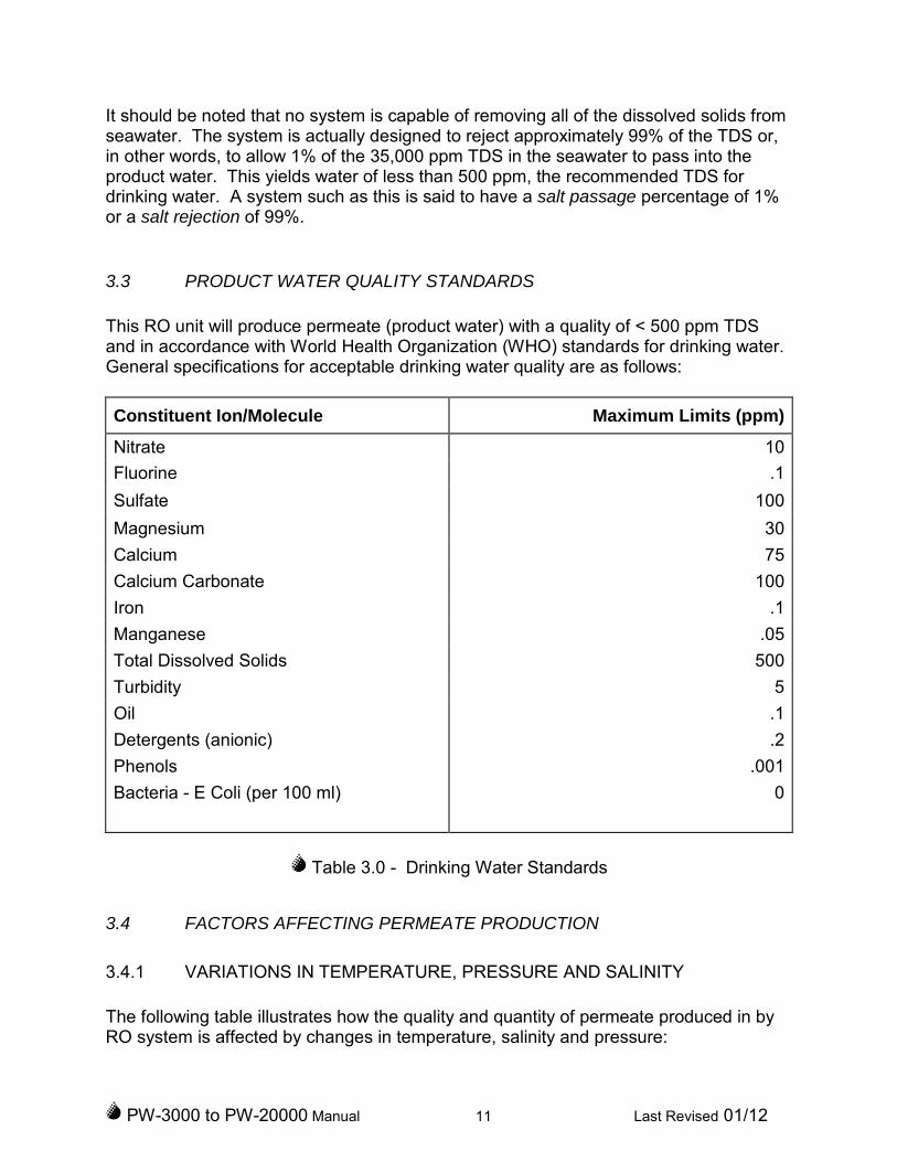
3.3 PRODUCT WATER QUALITY STANDARDS
This RO unit will produce permeate (product water) with a quality of < 500 ppm TDSand in accordance with World Health Organization (WHO) standards for drinking water.General specifications for acceptable drinking water quality are as follows:
Constituent Ion/Molecule Maximum Limits (ppm)
Nitrate 10
Fluorine .1
Sulfate 100
Magnesium 30
Calcium 75
Calcium Carbonate 100
Iron .1
Manganese .05
Total Dissolved Solids 500
Turbidity 5
Oil .1
Detergents (anionic) .2
Phenols .001
Bacteria - E Coli (per 100 ml) 0
Table 3.0 - Drinking Water Standards
3.4 FACTORS AFFECTING PERMEATE PRODUCTION
3.4.1 VARIATIONS IN TEMPERATURE, PRESSURE AND SALINITY
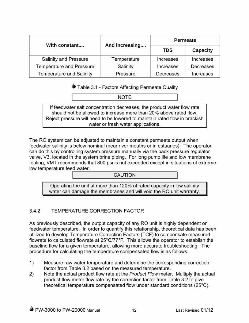
The following table illustrates how the quality and quantity of permeate produced in byRO system is affected by changes in temperature, salinity and pressure:
PW-3000 to PW-20000 Manual 12 Last Revised 01/12
With constant.... And increasing....Permeate
TDS Capacity
Salinity and Pressure Temperature Increases Increases
Temperature and Pressure Salinity Increases Decreases
Temperature and Salinity Pressure Decreases Increases
Table 3.1 - Factors Affecting Permeate Quality
NOTE
If feedwater salt concentration decreases, the product water flow rateshould not be allowed to increase more than 20% above rated flow.
Reject pressure will need to be lowered to maintain rated flow in brackishwater or fresh water applications.
The RO system can be adjusted to maintain a constant permeate output whenfeedwater salinity is below nominal (near river mouths or in estuaries). The operatorcan do this by controlling system pressure manually via the back pressure regulatorvalve, V3, located in the system brine piping. For long pump life and low membranefouling, VMT recommends that 800 psi is not exceeded except in situations of extremelow temperature feed water.
CAUTION
Operating the unit at more than 120% of rated capacity in low salinitywater can damage the membranes and will void the RO unit warranty.
3.4.2 TEMPERATURE CORRECTION FACTOR
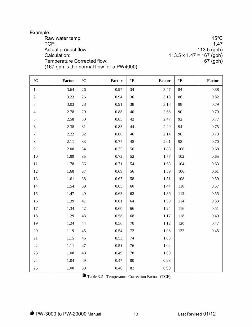
As previously described, the output capacity of any RO unit is highly dependent onfeedwater temperature. In order to quantify this relationship, theoretical data has beenutilized to develop Temperature Correction Factors (TCF) to compensate measuredflowrate to calculated flowrate at 25°C/77°F. This allows the operator to establish thebaseline flow for a given temperature, allowing more accurate troubleshooting. Theprocedure for calculating the temperature compensated flow is as follows:
1) Measure raw water temperature and determine the corresponding correctionfactor from Table 3.2 based on the measured temperature.
2) Note the actual product flow rate at the Product Flow meter. Multiply the actualproduct flow meter flow rate by the correction factor from Table 3.2 to givetheoretical temperature compensated flow under standard conditions (25°C).
PW-3000 to PW-20000 Manual 13 Last Revised 01/12
Example:Raw water temp: 15°CTCF: 1.47Actual product flow: 113.5 (gph)Calculation: 113.5 x 1.47 = 167 (gph)Temperature Corrected flow: 167 (gph)(167 gph is the normal flow for a PW4000)
°C Factor °C Factor °F Factor °F Factor
1 3.64 26 0.97 34 3.47 84 0.88
2 3.23 26 0.94 36 3.18 86 0.82
3 3.03 28 0.91 38 3.18 88 0.79
4 2.78 29 0.88 40 2.68 90 0.79
5 2.58 30 0.85 42 2.47 92 0.77
6 2.38 31 0.83 44 2.29 94 0.75
7 2.22 32 0.80 46 2.14 96 0.73
8 2.11 33 0.77 48 2.01 98 0.70
9 2.00 34 0.75 50 1.88 100 0.68
10 1.89 35 0.73 52 1.77 102 0.65
11 1.78 36 0.71 54 1.68 104 0.63
12 1.68 37 0.69 56 1.59 106 0.61
13 1.61 38 0.67 58 1.51 108 0.59
14 1.54 39 0.65 60 1.44 110 0.57
15 1.47 40 0.63 62 1.36 112 0.55
16 1.39 41 0.61 64 1.30 114 0.53
17 1.34 42 0.60 66 1.24 116 0.51
18 1.29 43 0.58 68 1.17 118 0.49
19 1.24 44 0.56 70 1.12 120 0.47
20 1.19 45 0.54 72 1.08 122 0.45
21 1.15 46 0.53 74 1.05
22 1.11 47 0.51 76 1.02
23 1.08 48 0.49 78 1.00
24 1.04 49 0.47 80 0.93
25 1.00 50 0.46 82 0.90
Table 3.2 - Temperature Correction Factors (TCF)

PW-3000 to PW-20000 Manual 14 Last Revised 01/12
3.5 OPERATIONAL DESCRIPTION
3.5.1 FILTRATION SYSTEM
Seawater supplied to the intake of the Village Marine RO desalination unit will initiallyflow through the raw water strainer, ST1, which removes large particulate matter.Once through the strainer, the raw water is supplied to the low pressure boost pump,P1, which raises the pressure of the water in order to provide enough positive feedpressure to flow through the filtration system and into the suction of the high pressurepump.
For units equipped with a (optional) Media Filtration System:
When a unit operates in areas where the raw water source of high turbidity ororganic materials, VMT recommends installing a media filtration system (IMF).The media pump and filter, is installed upstream of the watermaker and will removeparticles as small as 25 microns in diameter. The filtration media is comprised amultiple layers of specific materials that are specifically designed to removesuspended particulate matter from the raw water stream. The benefit is tosignificantly reduce the cleaning and replacement frequency for the micron filters.When the media filter is fully loaded (indicated by high filter differential pressure), theoperator initiates a backwash cleaning cycle designed to flush trapped particulatematter out of the filter and into the system drain. Please see the IMF manual or IMFbulletin for further details.
The raw water next passes through the micron filter array, F1 & F2, which is designedto reduce raw water turbidity to a nominal 5 microns in diameter. The micron filter arrayconsists of one 20 micron filter cartridge and one 5 micron filter cartridge.
Each filter housing contains one (1) filter element with an effective filtering area of 100ft2 and is equipped with an integral air/oil separator bleed. Bleed is continuouslydischarged to the reject header and overboard.
The discharge pressure from the filter housings is monitored by a pressure gauge,PG1, and pressure switch, PS1, that allow the operator to determine when the filterelements require cleaning or replacement.
3.5.2 REVERSE OSMOSIS SYSTEM
The clean and filtered raw water (now referred to as feedwater) is supplied to the inlet ofthe high pressure pump, P2. This pump raises feedwater pressure to 800 psi, thenominal pressure required for optimal system recovery. The pressurized feedwater

PW-3000 to PW-20000 Manual 15 Last Revised 01/12
then flows directly into the membrane array. The membrane array is an arrangementof fiberglass pressure vessels each containing a RO membrane element.
The pressurized feedwater flows along the membrane elements where reverse osmosistakes place (see Section 3.1). The feedwater flow is divided into two streams - the highpurity product stream (referred to as the permeate) and the increasingly concentratedreject stream (referred to as the brine or reject).
After exiting the membrane array, the brine (which contains higher concentrations ofsalts) flows through the back pressure regulator valve, V3. This manually adjustablevalve is used to control the back pressure through the membrane array. After passingthrough the back pressure regulator, the brine flows through the reject flow meter, FM1and exits the RO unit.
3.5.3 PRODUCT MONITORING SYSTEM
The product water stream (or permeate) flows past a conductivity sensor, whichprovides a signal to the water quality monitor. Depending on the concentration of totalof dissolved solids (TDS) in the permeate stream, the following occurs:
If permeate TDS is > 500 ppm, indicating poor quality water, a signal is sent to close the2-way product diversion valve, V6. This causes permeate system pressure to riseuntil it equals the activation set point of the permeate relief valve, V7. With the reliefvalve open, the poor quality water is diverted to the reject stream and away from yourstorage tanks. A product pressure gauge, PG3 is supplied to enable accurateadjustment of the product relief valve to about 40 psi in most installations.
If the permeate has < 500 ppm TDS, indicating good quality (drinking) water, a signal issent to open the product diversion valve. The relief valve then shuts allowing thepermeate to pass through the product flow meter, FM2 and then on to the potablewater storage tank(s).
3.5.4 MEMBRANE CLEANING SYSTEM
This RO unit includes a membrane cleaning system which provides a means forremoving performance degrading organic foulants and scale deposits from the ROmembranes (occurs approximately every 30 – 90 days during constant use). By usingthe filter housings as cleaning solution tanks, the pumps, a cleaning valve V5, and ahigh pressure bypass valve V4, the membranes can be chemically cleaned in place.Complete information and cleaning procedures can be found in Section 5.5.
PW-3000 to PW-20000 Manual 16 Last Revised 01/12
3.6 WATER QUALITY MONITOR
The Water Quality Monitor (MON) monitors and displays permeate salinity, temperatureand accumulated unit operating hours. It also provides operational mode control of thesystem product valve.
3.6.1 PUSHBUTTONS
Temperature – allows the operator to display permeate temperature (as opposed tothe normal permeate salinity display). By changing a jumper located on the back ofthe monitor, the temperature can be displayed in ºF or ºC.
Salinity Alarm Set Point – allows the operator to display and vary (via a control knoblocated on the back of the monitor) the salinity alarm set point.
Mode – allows the operator to bypass the normal automatic operation and manuallyclose the product valve (called DUMP mode, used, for instance, during cleaning).
3.6.2 DISPLAYS AND LIGHTS
Normal Operation – a green light is illuminated when the product valve is energizedand permeate is flowing through the product valve.
Dump/Cleaning – a yellow light is illuminated when the product valve is de-energizedand the product valve is closed.
Salinity Alarm – a red, flashing light indicates that permeate quality is above thesalinity set point.
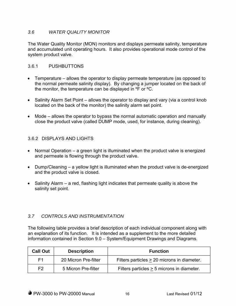
3.7 CONTROLS AND INSTRUMENTATION
The following table provides a brief description of each individual component along withan explanation of its function. It is intended as a supplement to the more detailedinformation contained in Section 9.0 – System/Equipment Drawings and Diagrams.
Call Out Description Function
F1 20 Micron Pre-filter Filters particles > 20 microns in diameter.
F2 5 Micron Pre-filter Filters particles > 5 microns in diameter.
PW-3000 to PW-20000 Manual 17 Last Revised 01/12
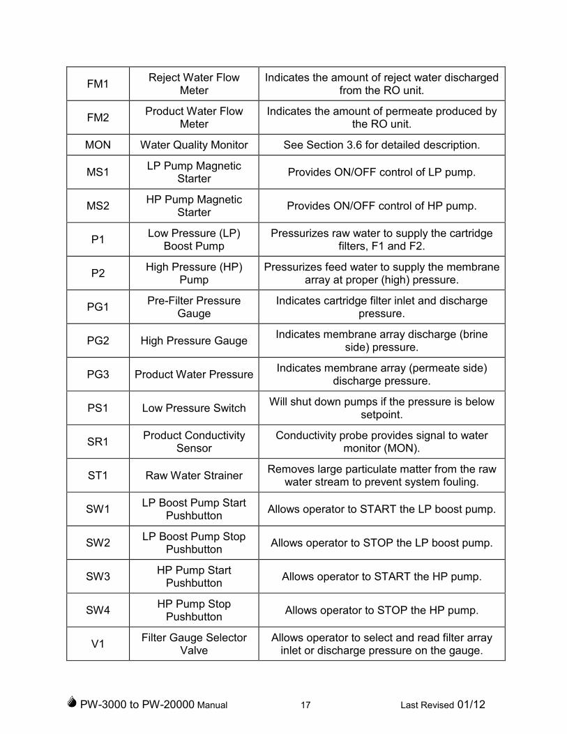
FM1Reject Water Flow
MeterIndicates the amount of reject water discharged
from the RO unit.
FM2Product Water Flow
MeterIndicates the amount of permeate produced by
the RO unit.
MON Water Quality Monitor See Section 3.6 for detailed description.
MS1LP Pump Magnetic
StarterProvides ON/OFF control of LP pump.
MS2HP Pump Magnetic
StarterProvides ON/OFF control of HP pump.
P1Low Pressure (LP)
Boost PumpPressurizes raw water to supply the cartridge
filters, F1 and F2.
P2High Pressure (HP)
PumpPressurizes feed water to supply the membrane
array at proper (high) pressure.
PG1Pre-Filter Pressure
GaugeIndicates cartridge filter inlet and discharge
pressure.
PG2 High Pressure GaugeIndicates membrane array discharge (brine
side) pressure.
PG3 Product Water PressureIndicates membrane array (permeate side)
discharge pressure.
PS1 Low Pressure SwitchWill shut down pumps if the pressure is below
setpoint.
SR1Product Conductivity
SensorConductivity probe provides signal to water
monitor (MON).
ST1 Raw Water StrainerRemoves large particulate matter from the raw
water stream to prevent system fouling.
SW1LP Boost Pump Start
PushbuttonAllows operator to START the LP boost pump.
SW2LP Boost Pump Stop
PushbuttonAllows operator to STOP the LP boost pump.
SW3HP Pump Start
PushbuttonAllows operator to START the HP pump.
SW4HP Pump Stop
PushbuttonAllows operator to STOP the HP pump.
V1Filter Gauge Selector
ValveAllows operator to select and read filter array
inlet or discharge pressure on the gauge.
PW-3000 to PW-20000 Manual 18 Last Revised 01/12
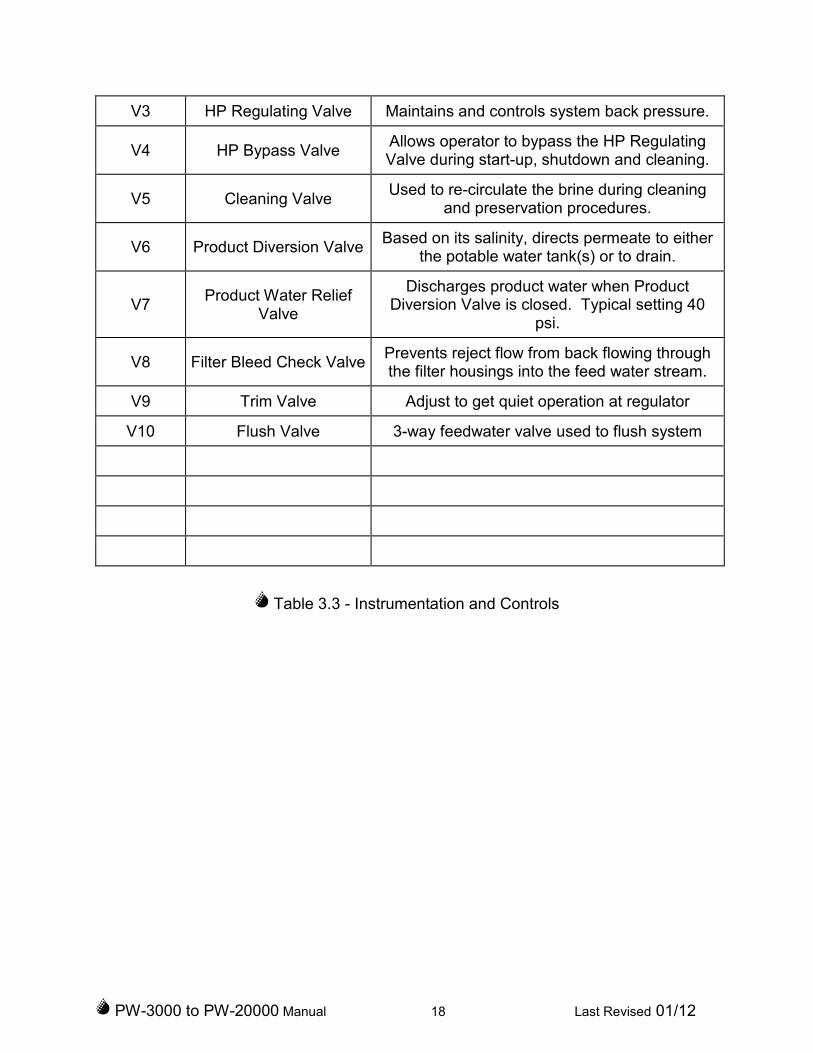
V3 HP Regulating Valve Maintains and controls system back pressure.
V4 HP Bypass ValveAllows operator to bypass the HP RegulatingValve during start-up, shutdown and cleaning.
V5 Cleaning ValveUsed to re-circulate the brine during cleaning
and preservation procedures.
V6 Product Diversion ValveBased on its salinity, directs permeate to either
the potable water tank(s) or to drain.
V7Product Water Relief
Valve
Discharges product water when ProductDiversion Valve is closed. Typical setting 40
psi.
V8 Filter Bleed Check ValvePrevents reject flow from back flowing throughthe filter housings into the feed water stream.
V9 Trim Valve Adjust to get quiet operation at regulator
V10 Flush Valve 3-way feedwater valve used to flush system
Table 3.3 - Instrumentation and Controls
PW-3000 to PW-20000 Manual 19 Last Revised 01/12
4.0 OPERATION
4.1 START-UP PROCEDURE
NOTE
The HP Pump should rotate in the counter-clockwise direction (whenfacing the protruding end of the shaft).
1) Check the HP pump oil level by observing sight gauge located on the pump.
2) On initial start up, check the drive belt tension by removing the belt guard. SeeSection 5.4 for detailed procedure.
WARNING
De-energize (lock out or disconnect) the electrical supply to RO unitbefore attempting to check or adjust drive belt tension. Serious injury to
personnel can result if the RO unit is started while checking drive belttension.
3) Open the raw saltwater supply to the unit. On pressurized feed systems, watermay now be flowing through the watermaker.
4) On initial start up, check the tightness of all lines and fittings.
5) If equipped with an IMF or other media filter, backwash and rinse media filter asrequired for initial startup or after long periods of standby. With fresh fill ofmedia, multiple backwash and rinse sequences will be required. See IMFmanual.
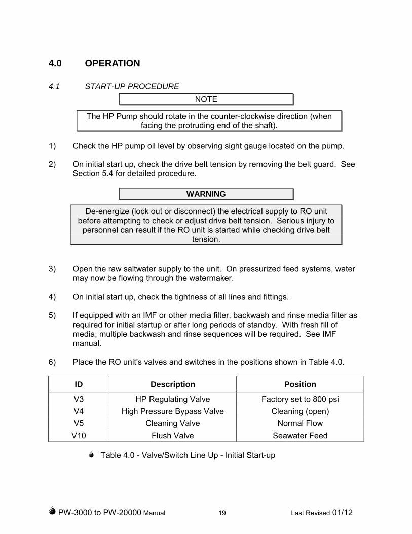
6) Place the RO unit's valves and switches in the positions shown in Table 4.0.
ID Description Position
V3 HP Regulating Valve Factory set to 800 psi
V4 High Pressure Bypass Valve Cleaning (open)
V5 Cleaning Valve Normal Flow
V10 Flush Valve Seawater Feed
Table 4.0 - Valve/Switch Line Up - Initial Start-up

PW-3000 to PW-20000 Manual 20 Last Revised 01/12
CAUTION
Failure to open the High Pressure Bypass Valve (which is required tobleed any entrapped air) can result in hydraulic shock to the system.
6) Verify electrical power is supplied to the RO unit.
CAUTION
The low pressure (LP) boost pump should not be started if the feed systempressure as read on the inlet side of the Pre-filter Pressure gauge is more than40 psi. Operate with only the HP pump if feed pressure is in excess of 40 psi to
avoid overpressure to the feed water system components.
7) Start the pumps in turn, feed pump (if equipped), boost pump and then the HPpump. At least 10 psi must be indicated on the discharge side of the Pre-filterPressure gauge.
8) Inspect all plumbing connections in the unit for leakage. Temperature variationsduring shipment may cause plumbing connections to seep when initially startedon-site. Secure the unit and repair any leaks prior to proceeding. Once the leakshave been repaired, open the raw water source and re-start the unit.
9) When flow through the reject discharge flow meter appears to be free of airbubbles, place the High Pressure Bypass Valve, V4, in the closed position byslowly turning the handle in the clockwise direction.
NOTE
When the High Pressure Bypass Valve is closed, the salinity of the initialpermeate produced may be temporarily high and will probably be
enough to temporarily energize the salinity alarm.
10) Observe the system pressure on the discharge side of the RO Membrane ArrayPressure gauge. For seawater applications, indicated pressure should be presetto 800 psi. If the indication is other than 800 psi, adjust the nut on top of the backpressure regulator valve, V3, using a wrench until the discharge side of the ROMembrane Array Pressure gauge indicates 800 psi. In conjunction withadjustment of the regulator, adjust the trim valve, V9, to find the quietestoperating point.

PW-3000 to PW-20000 Manual 21 Last Revised 01/12
WARNING
Pressure, as indicated on the inlet side of the RO Membrane Array gauge,should never exceed 1000 psi.
NOTE
The system pressure required to produce equivalent amounts of permeateis lower for fresh water sources (approximately 200 psi) and brackishwater sources (approximately 400 psi) than for seawater applications.
Reduce system pressure as necessary to maintain system output at nomore than 120% of rated capacity.
11) Normally, during start-up using seawater, the Salinity alarm (red) will remain litfor approximately 2 minutes. When the product water quality drops below 500ppm TDS, the green lamp will light. The water quality monitor will then open theproduct diversion valve, which will direct the product water to the product waterflow meter. If the green lamp does not light within 10 minutes, sample theproduct water from the pressure vessel sample valves and confirm with ahandheld salinity meter.
12) Observe the Product Flow meter. This flow meter indicates, in gallons perminute (gpm), the product water flow rate. Record the product flow after 5 hoursof operation (use the sample log sheet provided in Figure 5.1). This indicationwill provide the baseline used to determine RO membrane cleaningrequirements. Normally, a drop of 10-15% in the temperature corrected productwater production rate indicates the need for RO membrane cleaning (see Section3.4 for a more detailed information concerning variations in product flow).
13) Observe the Reject Flow meter. This flow meter indicates, in gallons per minute(gpm) the reject flow rate from the RO array. Record the reject flow after the first5 hours of operation (use the sample log sheet provided in Figure 5.1).
4.2 SHUTDOWN PROCEDURES
4.2.1 SHUTDOWN PROCEDURE (SHORT TERM)
1) Release the pressure from the system by turning the High Pressure BypassValve, V4, counter-clockwise to the Cleaning (open) position.
2) Secure the HP pump by pressing the red HP PUMP STOP button located on thefront panel.

PW-3000 to PW-20000 Manual 22 Last Revised 01/12
3) If required, secure the LP boost pump by pressing the red LP PUMP STOPbutton located on the front panel.
4) Secure the feedwater system by closing a feedwater valve upstream of the watermaker or by turning the Flush Valve, V10, to the midway position. If theanticipated shutdown period will be 24 hours or more, flush the system as perSection 4.3 - Flushing Procedure.
4.2.2 SHUTDOWN PROCEDURE (EXTENDED)
Since bacteria and biologic growth increases significantly the longer stagnant water is incontact with the membranes, the fresh flushing procedure (Section 4.3) should be usedwhenever the unit will be secured for more than 1 or 2 days. Although they do notattack the membranes or other system components directly, high concentrations ofbiological matter can block enough of the product water channels to cause a reductionof as much as 40% of the total system capacity.
CAUTION
Failure to follow the extended shutdown procedure can result inirreversible fouling to the RO membranes.
Bacterial contamination can be avoided by following the following procedures:
Flush the RO unit with non-chlorinated fresh water for 2 - 4 minutes. Reflush the RO unit for 2 - 4 minutes every 7 days. Or, Pickle the RO unit with a preservative solution. Refresh the preservative
every 3 months. Follow the preservation instructions provided in Section 5.6.
4.3 FRESH WATER FLUSH PROCEDURE
Note: Fresh flushing water should pass through the carbon flush filter supplied on thePW unit so it is non-chlorinated. Exposing the membranes to chlorinated water maycause irreversible membrane damage. The carbon filter element should be changedonce per year or after 50 flushes. It is designed to remove normal concentrations offree chlorine (0.5 to 1.0 ppm). Do not flush with shock-chlorinated water. Once thewatermaker is shut off and isolated, the flush procedure is:
1) Make sure the HP Bypass Valve, V4, is in the counterclockwise (open) position.
2) Turn the Flush Valve, V10, to the flush position to bring freshwater to the feed ofthe watermaker.
3) Start the LP boost pump.

PW-3000 to PW-20000 Manual 23 Last Revised 01/12
4) Once you have observed fresh water flow through Reject Flow meter, run thesystem for an additional 2 to 4 minutes. For greater flushing flow, start the HPpump as well.
5) Secure the pumps. Return the Flush Valve, V10, to midway position, isolatingthe watermaker.
5.0 MAINTENANCE INSTRUCTIONS
5.1 GENERAL
The service life of most of the system equipment is directly related to the raw water inletconditions. Improper maintenance will also significantly reduce the life expectancy ofthe major unit components (such as the membranes, filters and pumps) as well as thereliability of the unit as a whole. Under normal conditions, and with propermaintenance, a reverse osmosis membrane (which is the major consumable item)should have an effective service life somewhere between 1 to 2 years heavy use.
Da
ily
We
ekly
Mo
nth
ly
Qu
art
erly
Se
mi-A
nn
ua
lly
An
nua
lly
As
Re
qu
ired
La
bo
rH
ou
rs(a
pp
roxim
ate
)
Clean and inspect strainer basket 0.3
Clean and inspect micron filter(s) 0.5
Replace filter(s) 0.5
Clean membranes 4.0
Replace membranes 2.0
Inspect pump drive belt 1.0
Check pump oil level 0.1
Change pump oil(1) 1.0
Lubricate pump motors 1.0
Backflush media filter(2) 0.3
(1) After first 50 hours and every 500 hours thereafter(2) For units equipped with the optional media filtration system.
Figure 5.0 - Maintenance Task Chart

PW-3000 to PW-20000 Manual 24 Last Revised 01/12
5.2 RAW WATER STRAINER INSPECTION
1) Isolate the raw water supply and open the strainer housing.
2) Remove the screen from the strainer bowl. Remove any debris from screen andinspect the screen closely for damage. Replace as required.
3) Check the sealing gasket or o-ring is in good condition, and keeping the seal inplace install the screen and reclose the strainer housing hand tight. Start the ROand check for leaks.
5.3 FILTER ELEMENT CLEANING OR REPLACEMENT
The filter elements should be replaced when the discharge side of the pressure gaugedrops below 5 psi or the differential pressure is 20 psi. Each PW3000-20000 employs afilter array consisting of one (1) 20 micron, 100 ft2 filter in series with one (1) 5 micron,100 ft2 filter. VMT filters can be washed and re-used 2-3 times provided it is notcontaminated with oil or organic growth.
Description Qty VMT Part #
Micron filter, 20 micron, 100 ft2 1 33-2100
Micron filter, 5 micron, 100 ft2 1 33-5100
O-ring, filter lid, 100 ft2 2 30-0405
Filter, complete assembly, 100 ft2 2 30-4353
Table 5.0 - Filter Tank Parts List.
CAUTION
VMT filter cartridges are specifically designed for RO applications andconstructed with an oil attractive polypropylene. Use of non-approved
cartridges will void the RO unit warranty.
Replace the filter element(s) using the following procedure:
1) Secure the RO unit. Close the raw water supply (external) to RO unit.
2) Loosen and remove the bolts or wing-nuts that hold the filter tank lid in place.Remove the tank lid.
3) Remove the filter element. If required, first break the filter seal by rocking thefilter from side to side.
PW-3000 to PW-20000 Manual 25 Last Revised 01/12
4) The filter element may be cleaned by flushing it with water to remove foreignmatter from the filter pleats. If the filter element appears oil-fouled or is damagedin any way, discard it and install a new element.
5) Reinstall the filter element. Be sure to install the filter element with the endmarked "TOP" upwards. Ensure a proper seal by pressing the filter elementdown into place until it reaches the bottom and is fully seated.
6) Reinstall the filter tank lid. Tighten the bolts or nuts.
7) After the filter element has been changed, operate the RO unit and check forleaks.
5.4 DRIVE BELT INSPECTION AND REPLACEMENT
Proper adjustment of the HP pump drive belt(s) is essential for proper operation of thesystem. The drive belt(s) should be inspected for cracking, fraying and excessive wear.Replace the belts immediately it the inspection indicates that the belt(s) are damaged.
WARNING
Disconnect electrical supply to RO unit before attempting to check.Serious injury to personnel can result if RO unit is started when checking
drive belt.
1) Remove the mounting screws that hold the left front panel in place and removethe panel.
2) Inspect drive belt carefully for wear and proper tension. The belt should deflectapproximately ½ " when a force of 6-9 lbs is applied at a point halfway betweenthe pulleys. Remember that cogged drive belts are never kept as tight as V drivebelts, and overtightened belts will create a squealing sound and can damagebearings. Adjust the base plate as required to obtain proper belt tension.
3) If the drive belt is damaged or shows any evidence of excessive wear, replacethe drive belt:
a) Locate the HP pump's mounting nuts on the adjustable pump base.Loosen the nuts to relax the belt tension.
b) Remove the old drive belt and install new one ensuring they are properlypositioned in the pulleys.
PW-3000 to PW-20000 Manual 26 Last Revised 01/12
c) Check the drive belt tension. Adjust the base plate as required to obtainproper belt tension.
(d) Be sure to properly align the pump and motor pulleys using a straightedge (at a minimum). After the belt has been sufficiently tightened andaligned, secure the HP pump by tightening the pump mounting nuts.
4) Replace the side panel on the RO unit
5.5 RO MEMBRANE CLEANING
This section is designed to guide the operator in the periodic chemical cleaning of ROmembrane elements used in the PW3000-20000 unit. The basic procedure for allcleaning and preservative treatments is the same - a specific chemical solution iscirculated through the system for a pre-determined length of time.
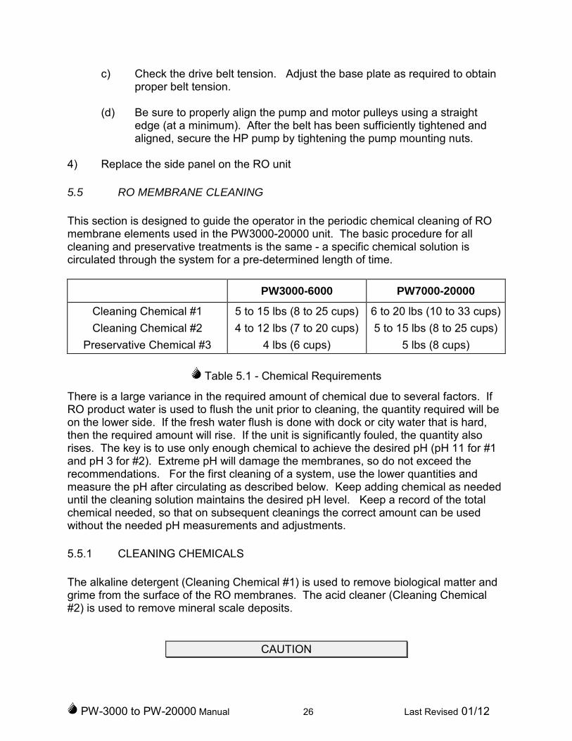
PW3000-6000 PW7000-20000
Cleaning Chemical #1 5 to 15 lbs (8 to 25 cups) 6 to 20 lbs (10 to 33 cups)
Cleaning Chemical #2 4 to 12 lbs (7 to 20 cups) 5 to 15 lbs (8 to 25 cups)
Preservative Chemical #3 4 lbs (6 cups) 5 lbs (8 cups)
Table 5.1 - Chemical Requirements
There is a large variance in the required amount of chemical due to several factors. IfRO product water is used to flush the unit prior to cleaning, the quantity required will beon the lower side. If the fresh water flush is done with dock or city water that is hard,then the required amount will rise. If the unit is significantly fouled, the quantity alsorises. The key is to use only enough chemical to achieve the desired pH (pH 11 for #1and pH 3 for #2). Extreme pH will damage the membranes, so do not exceed therecommendations. For the first cleaning of a system, use the lower quantities andmeasure the pH after circulating as described below. Keep adding chemical as neededuntil the cleaning solution maintains the desired pH level. Keep a record of the totalchemical needed, so that on subsequent cleanings the correct amount can be usedwithout the needed pH measurements and adjustments.
5.5.1 CLEANING CHEMICALS
The alkaline detergent (Cleaning Chemical #1) is used to remove biological matter andgrime from the surface of the RO membranes. The acid cleaner (Cleaning Chemical#2) is used to remove mineral scale deposits.
CAUTION
PW-3000 to PW-20000 Manual 27 Last Revised 01/12
The use of chemicals or cleaning methods other than those outlined belowwill void the RO unit warranty. Non-ionic surfactants for membrane
cleaning or other chemicals not approved in writing by VMT will void theRO unit warranty.
5.5.2 WHEN TO CLEAN
During normal operations, mineral scale and biological matter will foul the ROmembranes. These deposits build up over time and will eventually cause a loss ofproduct water output, salt rejection capability, or both. The RO elements should becleaned whenever the temperature corrected product water output drops by 10-15%from the initial baseline established during the first hours of operation with newmembranes. Prior to cleaning the membranes, verify that any reduction in productoutput is not the result of a corresponding variation in raw water inlet temperature orsalinity. See Section 3.4 for more detailed information.
NOTE
Product water output of the system is dependent upon feedwatertemperature, RO feed pressure and feedwater salinity. Reductions in
product water output due to these factors are normal and may not indicatethe need for membrane cleaning. See Section 3.4 for more detail.
Use the following procedure to clean the RO elements:
1) Flush the watermaker per section 4.3, so it is filled with fresh water, notseawater.
2) Dissolve the appropriate amount of Cleaning Chemical #1 (see Table 5.1) in apail of fresh water. Make sure that that the chemical is completely dissolved (usewarm water if necessary).
NOTE
Cleaning Chemical #1 is an alkaline detergent. Use appropriate safetyprecautions.
3) Verify the High Pressure Bypass Valve, V4, is in its Cleaning (open) position.
4) Place the Cleaning Valve, V5, in the Cleaning Flow position.
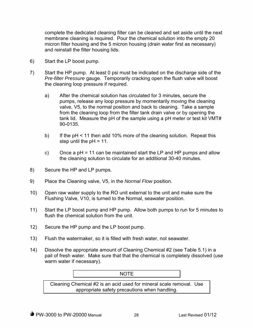
5) Remove the filter elements from both filter tanks and replace the 5 micron filterwith a dedicated cleaning filter (5 micron). A dedicated cleaning filter should beused to prevent fouling of the operational filters. When the cleaning process is
PW-3000 to PW-20000 Manual 28 Last Revised 01/12
complete the dedicated cleaning filter can be cleaned and set aside until the nextmembrane cleaning is required. Pour the chemical solution into the empty 20micron filter housing and the 5 micron housing (drain water first as necessary)and reinstall the filter housing lids.
6) Start the LP boost pump.
7) Start the HP pump. At least 0 psi must be indicated on the discharge side of thePre-filter Pressure gauge. Temporarily cracking open the flush valve will boostthe cleaning loop pressure if required.
a) After the chemical solution has circulated for 3 minutes, secure thepumps, release any loop pressure by momentarily moving the cleaningvalve, V5, to the normal position and back to cleaning. Take a samplefrom the cleaning loop from the filter tank drain valve or by opening thetank lid. Measure the pH of the sample using a pH meter or test kit VMT#90-0135.
b) If the pH < 11 then add 10% more of the cleaning solution. Repeat thisstep until the pH = 11.
c) Once a pH = 11 can be maintained start the LP and HP pumps and allowthe cleaning solution to circulate for an additional 30-40 minutes.
8) Secure the HP and LP pumps.
9) Place the Cleaning valve, V5, in the Normal Flow position.
10) Open raw water supply to the RO unit external to the unit and make sure theFlushing Valve, V10, is turned to the Normal, seawater position.
11) Start the LP boost pump and HP pump. Allow both pumps to run for 5 minutes toflush the chemical solution from the unit.
12) Secure the HP pump and the LP boost pump.
13) Flush the watermaker, so it is filled with fresh water, not seawater.
14) Dissolve the appropriate amount of Cleaning Chemical #2 (see Table 5.1) in apail of fresh water. Make sure that that the chemical is completely dissolved (usewarm water if necessary).
NOTE
Cleaning Chemical #2 is an acid used for mineral scale removal. Useappropriate safety precautions when handling.
PW-3000 to PW-20000 Manual 29 Last Revised 01/12
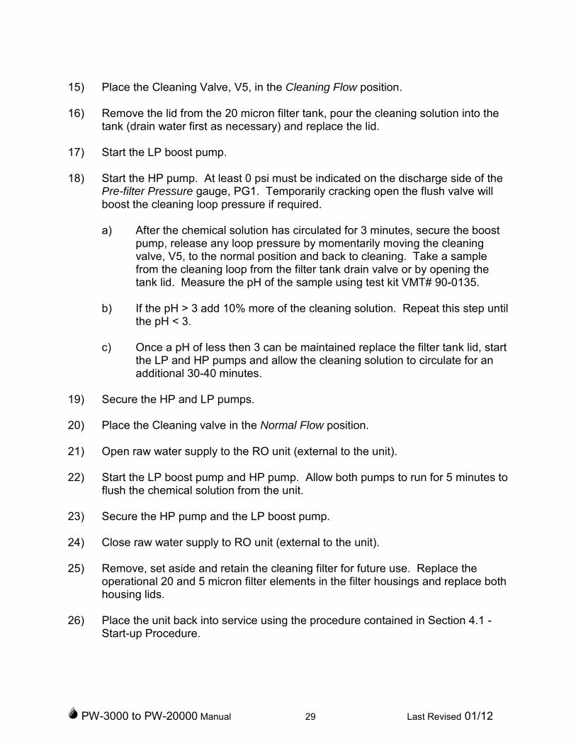
15) Place the Cleaning Valve, V5, in the Cleaning Flow position.
16) Remove the lid from the 20 micron filter tank, pour the cleaning solution into thetank (drain water first as necessary) and replace the lid.
17) Start the LP boost pump.
18) Start the HP pump. At least 0 psi must be indicated on the discharge side of thePre-filter Pressure gauge, PG1. Temporarily cracking open the flush valve willboost the cleaning loop pressure if required.
a) After the chemical solution has circulated for 3 minutes, secure the boostpump, release any loop pressure by momentarily moving the cleaningvalve, V5, to the normal position and back to cleaning. Take a samplefrom the cleaning loop from the filter tank drain valve or by opening thetank lid. Measure the pH of the sample using test kit VMT# 90-0135.
b) If the pH > 3 add 10% more of the cleaning solution. Repeat this step untilthe pH < 3.
c) Once a pH of less then 3 can be maintained replace the filter tank lid, startthe LP and HP pumps and allow the cleaning solution to circulate for anadditional 30-40 minutes.
19) Secure the HP and LP pumps.
20) Place the Cleaning valve in the Normal Flow position.
21) Open raw water supply to the RO unit (external to the unit).
22) Start the LP boost pump and HP pump. Allow both pumps to run for 5 minutes toflush the chemical solution from the unit.
23) Secure the HP pump and the LP boost pump.
24) Close raw water supply to RO unit (external to the unit).
25) Remove, set aside and retain the cleaning filter for future use. Replace theoperational 20 and 5 micron filter elements in the filter housings and replace bothhousing lids.
26) Place the unit back into service using the procedure contained in Section 4.1 -Start-up Procedure.
PW-3000 to PW-20000 Manual 30 Last Revised 01/12
5.6 RO ELEMENT PRESERVATION / PICKLING
During periods when the RO unit is to be shut down for an extended period of time, it isnecessary to circulate a preservative solution through the membranes to prevent thegrowth of biological organisms. Use the following procedure to preserve the ROelements:
1) Secure the raw water supply to RO unit (external to the unit).
2) Dissolve the appropriate amount of Cleaning Chemical #3 (see Table 5.1) in apail of non-chlorinated product water. Make sure that that the chemical iscompletely dissolved (use warm water if necessary).
NOTE
Preservative Chemical #3 is a food-grade preservative. See warning labelon package and observe all safety precautions on label.
3) Flush the watermaker, so it is filled with fresh water, not seawater (see section4.3)
4) Make sure the High Pressure Bypass Valve is in the Cleaning (open) position.
5) Place the Cleaning Valve in the Cleaning Flow position.
6) Remove one of the filter housing lids (draining water as necessary) and pour inthe preservative solution prepared in step #1. Reinstall the lid. Leave the filterselements in place.
7) Start the LP boost pump.
8) Start the HP pump. At least 0 psi must be indicated on the discharge side of thePre-filter Pressure gauge. Temporarily cracking open the flush valve will boostthe cleaning loop pressure if required. Allow the chemical solution to circulate for10 minutes.
9) Secure the LP and HP pumps.
10) The system is now properly conditioned and may be left idle for an extendedperiod of time. This preservation procedure (including the fresh flush to removeold pickling solution) should be repeated at least every 3 months during theshutdown. In colder climates the interval between preservation cycles may beextended to 6 months.

PW-3000 to PW-20000 Manual 31 Last Revised 01/12
5.7 RESTARTING UNIT AFTER PRESERVATION
Restart unit using the procedure contained in Section 4.1 - Start-up Procedure. Use theMODE button on the Water Quality Monitor to light the DUMP lamp for the first 15minutes of production to make sure all preservative is flushed clear prior to filling thefresh water tanks.
5.8 HIGH PRESSURE PUMP OIL CHANGE
See equipment literature in back of this manual for instructions for changing the oil onyour particular pump.
5.9 MOTOR LUBRICATION
Locate the grease fittings on the electric motor. Use a clean cloth to wipe this fittingclean. If applicable, remove any caps. Free the drain hole of any hard grease (use apiece of wire if necessary). Add 2-3 strokes of grease using a low pressure grease gun(see Table 5.2 for grease type).
Location Type
High pressure pump oil VMT pump oil #85-0050
High pressure pump motor grease
Shell Oil Dolium RTexaco Premium RB
Exxon Mobil PolyrexEMChevron SRI
O-rings & gaskets Glycerin or silicone lubricant
Table 5.2 - Lubrication Requirements
5.10 INSPECTION LOG
Figure 5.2 depicts a sample operation log for the PW3000-20000 RO unit. The operatorof the RO unit should establish a program for entering the required data on a regularbasis. Maintaining accurate operational data is the first, and most important, step indetermining preventative maintenance requirements and reducing system downtime.The data maintained in the log must be provided by the Purchaser to make any ROelement warranty claim. Figure 5.3 depicts a sample discrepancy report that may beused for reporting and tracking problems with the RO unit.
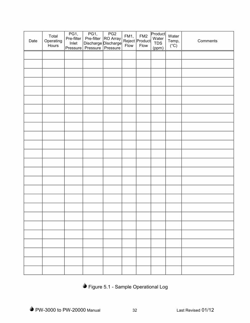
PW-3000 to PW-20000 Manual 32 Last Revised 01/12
DateTotal
OperatingHours
PG1,Pre-filter
InletPressure
PG1,Pre-filter
DischargePressure
PG2RO ArrayDischargePressure
FM1,RejectFlow
FM2Product
Flow
ProductWaterTDS
(ppm)
WaterTemp,(°C)
Comments
Figure 5.1 - Sample Operational Log

PW-3000 to PW-20000 Manual 33 Last Revised 01/12
COMMENT/DISCREPANCY REPORT
Village Marine Tec.
RO Desalinator Model PW-3000 to PW-20000
Plant No: Date:Log Task No: Time:System Affected: Technician :
Comment/Discrepancy:
Corrective Action:
Action Taken:
Date Completed:Printed Name:Signature:
Figure 5.2 - Sample Discrepancy Report
PW-3000 to PW-20000 Manual 34 Last Revised 01/12
6.0 PRESSURE VESSEL AND MEMBRANES
6.1 PRESSURE VESSEL DISASSEMBLY
NOTE
It is not necessary to remove a pressure vessel from the RO unit fordisassembly.
1) Disconnect all plumbing connections from the pressure vessel to bedisassembled.
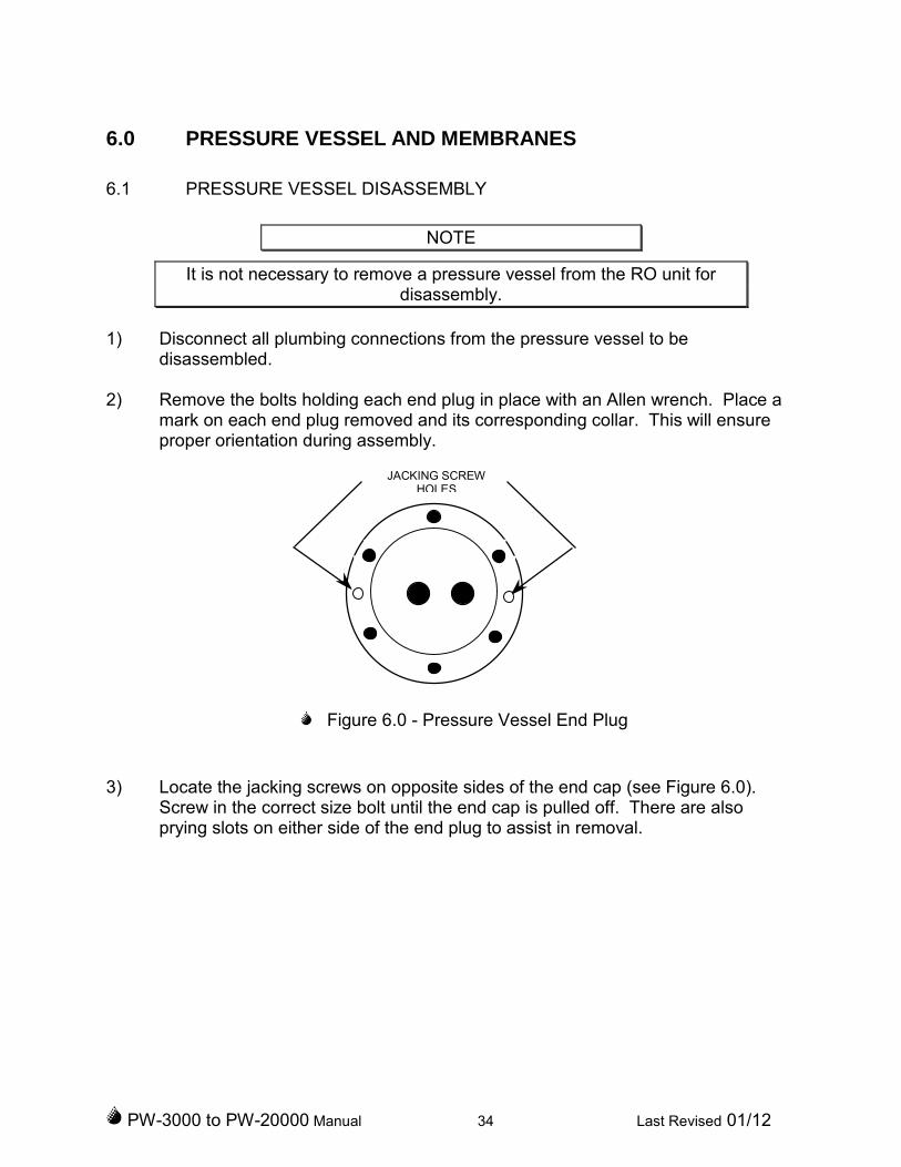
2) Remove the bolts holding each end plug in place with an Allen wrench. Place amark on each end plug removed and its corresponding collar. This will ensureproper orientation during assembly.
Figure 6.0 - Pressure Vessel End Plug
3) Locate the jacking screws on opposite sides of the end cap (see Figure 6.0).Screw in the correct size bolt until the end cap is pulled off. There are alsoprying slots on either side of the end plug to assist in removal.
JACKING SCREWHOLES

PW-3000 to PW-20000 Manual 35 Last Revised 01/12
Figure 6.1 - Brine Seal Orientation
4) Note which end of the pressure vessel the brine seal is visible from. This is thefeed end of the pressure vessel. When reinstalling the RO membrane, the brineseal must be located at the feed end of the pressure vessel. Note the feed flowdirection marked by a sticker on the outside of the pressure vessel, or trace theflow direction from the high pressure pump to confirm the high pressure flowdirection. See Figure 6.1.
CAUTION
Never force a membrane out of a pressure vessel by applying pressure onthe product water tube (center tube) as this will damage the membrane. Ifthe membrane is difficult to remove, use a length of 2" plastic pipe to apply
pressure on the protected end of membrane.
5) Whenever possible, remove the membrane from the discharge end of thepressure vessel (opposite the brine seal). This is accomplished by pushing onthe membrane from the feed end of the pressure vessel until it is visible at thedischarge end. Then grasp the protruding membrane and pull it out of pressurevessel. Place the membrane in a clean area.
6) Remove the product water o-rings and end plug o-ring from each end plug forinspection. The product water o-rings are internal o-rings located inside thecenter hole in the end cap.
PW-3000 to PW-20000 Manual 36 Last Revised 01/12
6.2 PRESSURE VESSEL ASSEMBLY
1) Clean all parts thoroughly. Inspect the o-rings on all fittings. Replace any partsthat are damaged.
NOTE
Do not apply Teflon tape or other sealant to straight thread fittings such asthose used on HP hose assemblies and their adapters.
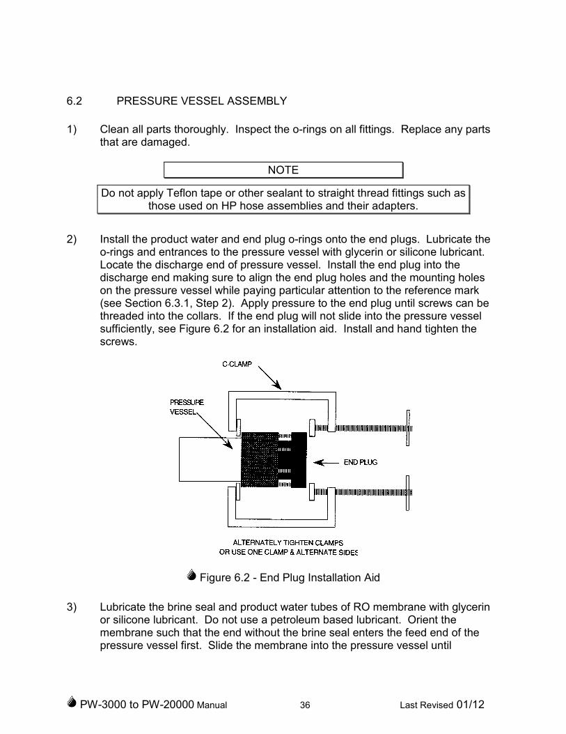
2) Install the product water and end plug o-rings onto the end plugs. Lubricate theo-rings and entrances to the pressure vessel with glycerin or silicone lubricant.Locate the discharge end of pressure vessel. Install the end plug into thedischarge end making sure to align the end plug holes and the mounting holeson the pressure vessel while paying particular attention to the reference mark(see Section 6.3.1, Step 2). Apply pressure to the end plug until screws can bethreaded into the collars. If the end plug will not slide into the pressure vesselsufficiently, see Figure 6.2 for an installation aid. Install and hand tighten thescrews.
Figure 6.2 - End Plug Installation Aid
3) Lubricate the brine seal and product water tubes of RO membrane with glycerinor silicone lubricant. Do not use a petroleum based lubricant. Orient themembrane such that the end without the brine seal enters the feed end of thepressure vessel first. Slide the membrane into the pressure vessel until
PW-3000 to PW-20000 Manual 37 Last Revised 01/12
resistance is felt. Continue to apply moderate pressure until the product watertube seats in the end plug.
4) Install the remaining end plug making sure to align the end plug holes with themounting holes on the pressure vessel while paying particular attention to thereference mark (see Section 6.3.1, Step 2). Apply moderate pressure to the endplug until the screws can be threaded into the collar. If the end plug will not slideinto the pressure vessel sufficiently, see Figure 6.2 for installation aid. Install andhand tighten the capscrews.
5) Make sure that antiseize compound is applied to each screw before the finaltightening and torque the screws to 15 ft-lbs.
6) Reconnect all plumbing connections to pressure vessels.
PW-3000 to PW-20000 Manual 38 Last Revised 01/12
7.0 PRESERVATION FOR STORAGE
When the Village Marine Tec RO unit is to be shut down for an extended period of time,it is necessary take steps to prevent the growth of biological organisms and to preventthe water in the RO unit from freezing. Either continue to flush the unit with fresh watereach week, or circulate a preservative solution (see section 5.6). If the unit will at anytime be exposed to air temperatures of 32ºF (0ºC) or less, the membranes must beremoved and the unit fully drained or the unit filled with an anti freeze solution such aspropylene glycol.
8.0 TROUBLESHOOTING
No amount of trouble shooting advice can replace common sense and direct plantknowledge gained through the operation and maintenance of your unit. However ourexperience taking tec calls suggests some points to check.
1. Always verify proper valve configuration for each of the operational modesselected. Verify valve positions for valves within the unit and also external valvesare open as required.
2. Always check for positive pressure at the HP pump suction. Many problemsstem from low or erratic feed water supply. Check filters, strainer, seacock,boost pumps, etc to be sure of flooded suction to the HP pump.
3. Always check for loose connections or broken wires when inspecting electricalparts. Checking for continuity and solid contact can sometimes avoid hours oftroubleshooting effort.
4. Prior to cleaning or replacing membranes, verify that any reduction in productoutput is not the result of a corresponding variation in raw water inlet temperatureor salinity. See Section 3.4 for more detailed information.
Call or email us at the Village Marine Tec Service representative or distributor forassistance.

PW-3000 to PW-20000 Manual 39 Last Revised 01/12
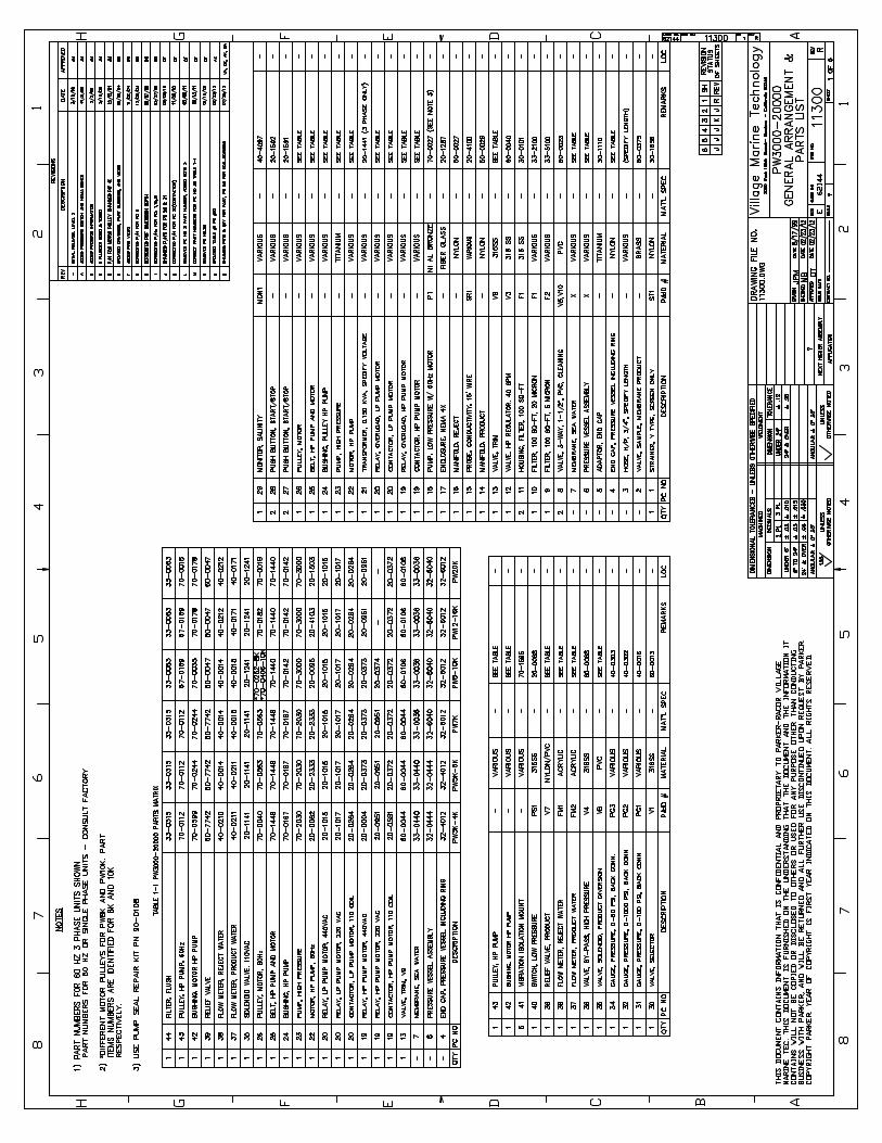
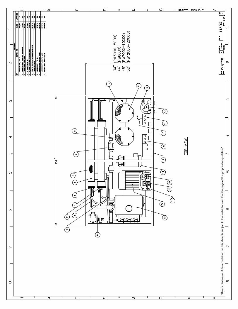
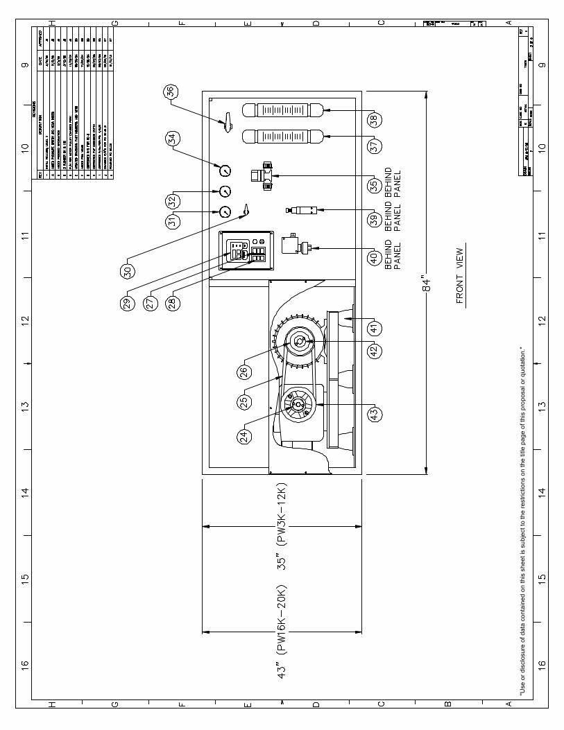
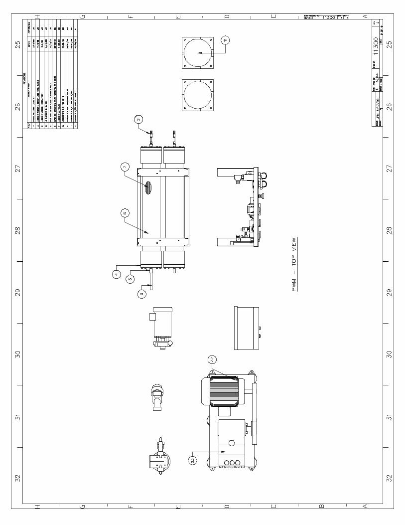
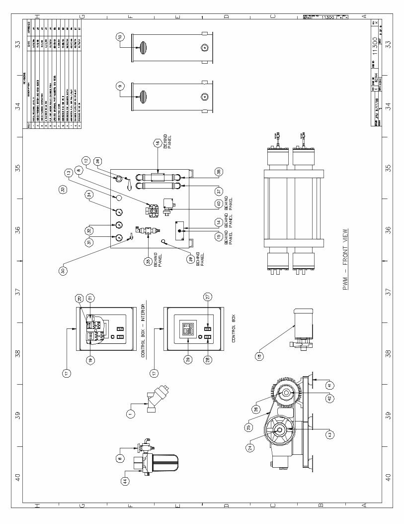
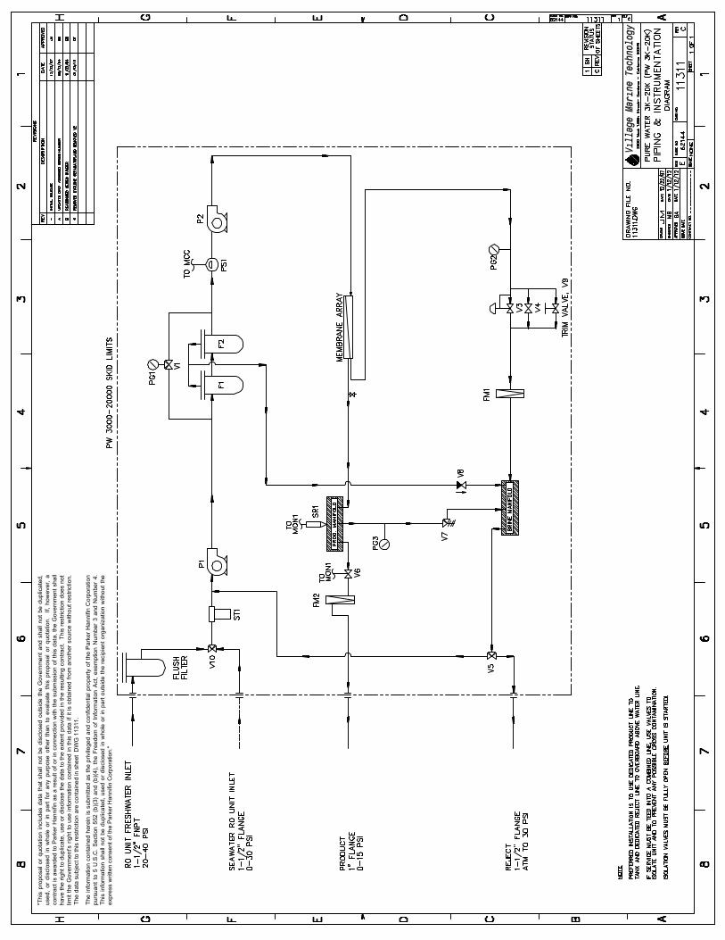
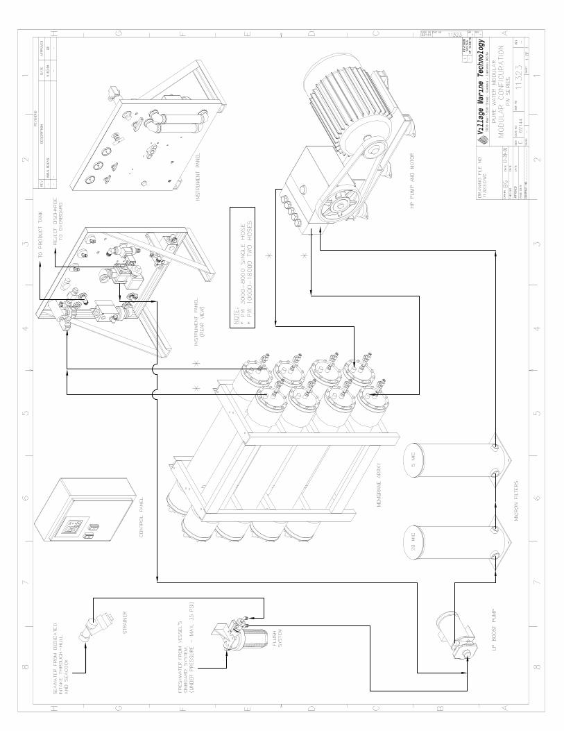
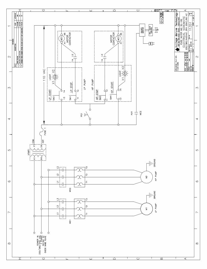
9.0 SYSTEM DRAWINGS AND DIAGRAMS AND PARTS LIST
"Use
or
dis
clo
su
reo
fd
ata
co
nta
ine
do
nth
issh
ee
tis
su
bje
ct
toth
ere
str
ictio
ns
on
the
title
pa
ge
of
this
pro
po
salo
rq
uo
tatio
n."
"Use
or
dis
clo
su
reo
fd
ata
con
tain
ed
on
this
sh
ee
tis
sub
ject
toth
ere
str
ictio
ns
on
the
title
pa
ge
ofth
isp
rop
osa
lo
rq
uota
tion
."

"Use
or
dis
closu
reof
data
conta
ined
on
this
shee
tis
subje
ctto
the
restr
ictio
ns
on
the
title
pag
eofth
ispro
posalor
qu
ota
tion."


"Th
isp
ropo
sal
or
quo
tatio
nin
cludes
data
that
shall
not
be
dis
close
do
uts
ide
the
Go
ve
rnm
ent
and
shall
not
be
dup
lica
ted,
use
d,
or
dis
close
din
whole
or
inp
art
for
any
purp
ose
oth
er
than
toe
valu
ate
this
pro
po
sal
or
quo
tation.
If,
how
ever,
acon
tract
isa
wa
rded
toP
ark
er
Han
nifin
as
are
sult
of
or
inconn
ect
ion
with
the
subm
issio
no
fth
isd
ata
,th
eG
ove
rnm
ent
shall
have
the
rig
ht
tod
uplic
ate
,use
or
dis
close
the
data
toth
ee
xtent
pro
vided
inth
ere
sultin
gcon
tract.
This
restr
iction
does
not
limit
the
Govern
men
t'srig
ht
touse
info
rma
tion
con
tain
ed
inth
isd
ata
ifit
iso
bta
ined
fro
ma
no
ther
sou
rce
witho
ut
restr
iction.
The
data
subje
ctto
this
rest
rict
ion
are
conta
ine
din
sheet
DW
G1
13
11
.
The
info
rma
tion
con
tain
ed
here
inis
sub
mitte
das
the
privile
ged
and
con
fide
ntia
lp
rop
ert
yo
fth
eP
ark
er
Han
nifin
Corp
ora
tion
purs
uant
to5
U.S
.C.
Sect
ion
552
(b)(
3)
and
(b)(
4),
the
Fre
edom
of
Info
rmatio
nA
ct,
exe
mp
tion
Nu
mber
3a
nd
Nu
mber
4.
This
info
rma
tion
shall
not
be
dup
lica
ted,
use
do
rd
iscl
ose
din
whole
or
inp
art
outs
ide
the
recip
ient
org
an
izatio
nw
itho
ut
the
exp
ress
written
con
sento
fth
eP
ark
er
Han
nifin
Co
rpora
tion."

PW3000-18000 Manual 43 Last Revised 4/08
10.0 MANUFACTURER'S LITERATURE AND OPTIONS


REVISION C

TABLE OF CONTENTS INTRODUCTION..................................................................................................................................................................... 1 INITIAL START-UP INFORMATION...................................................................................................................................... 2
LUBRICATION .................................................................................................................................................................... 2 PUMP FLOW DESIGN........................................................................................................................................................ 2 PULLEY SELECTION ......................................................................................................................................................... 2 MOTOR SELECTION.......................................................................................................................................................... 3 MOUNTING THE PUMP ..................................................................................................................................................... 3 DISCHARGE PLUMBING ................................................................................................................................................... 3 PUMPED FLUIDS ............................................................................................................................................................... 4 STORAGE ........................................................................................................................................................................... 4
INLET CONDITION CHECKLIST........................................................................................................................................... 5 INLET SUPPLY ................................................................................................................................................................... 5 INLET LINE SIZE ................................................................................................................................................................ 5 INLET PRESSURE.............................................................................................................................................................. 5 INLET ACCESSORIES ....................................................................................................................................................... 6
PREVENTIVE MAINTENANCE SCHEDULE......................................................................................................................... 7 MAINTENANCE RECORD..................................................................................................................................................... 8 TROUBLESHOOTING............................................................................................................................................................ 9 SERVICE............................................................................................................................................................................... 12
INTRODUCTION ............................................................................................................................................................... 12 TOOLS NEEDED .............................................................................................................................................................. 12 DETACHING THE MANIFOLD FROM THE CRANKCASE .............................................................................................. 13 SERVICING THE CRANKCASE ....................................................................................................................................... 13 PLUG, OIL DRAIN, O-RING REPLACEMENT.................................................................................................................. 13 OIL SEAL REPLACEMENT............................................................................................................................................... 13 BEARING SIDE PLATE O-RING/SEAL REPLACEMENT ................................................................................................ 15 COVER, CRANKCASE O-RING REPLACEMENT ........................................................................................................... 16 CRANKSHAFT BEARING, CONNECTING ROD-PISTON ASSEMBLY SERVICE ......................................................... 17 SERVICING THE MANIFOLD........................................................................................................................................... 18 ADAPTER O-RING REPLACEMENT................................................................................................................................ 18 VALVE ASSEMBLY SERVICING ...................................................................................................................................... 18 MANIFOLD SEAL SERVICING ......................................................................................................................................... 20 ATTACHING THE MANIFOLD TO THE CRANKCASE .................................................................................................... 22
3P20 DRAWINGS................................................................................................................................................................. 23
LIST OF FIGURES Fig. 1: Oil Level Sight Glass Detail. ........................................................................................................................................ 2 Fig. 2: Manifold Assembly Removal...................................................................................................................................... 13 Fig. 3: Oil Seal Removal View............................................................................................................................................... 14 Fig. 4: Plunger Assembly View ............................................................................................................................................. 14 Fig. 5: Plunger Retaining Nut Assembly ............................................................................................................................... 15 Fig. 7: Bolt tightening sequence............................................................................................................................................ 17 Fig. 8: Manifold Assembly ..................................................................................................................................................... 18 Fig. 9: Valve Assembly.......................................................................................................................................................... 19 Fig. 10: Orientation for Manifold Seal Servicing.................................................................................................................... 20 Fig. 11: Weep Ring Extraction ............................................................................................................................................. 21 Fig. 12: High-Pressure Seals Installation View.................................................................................................................... 21 Fig. 13: Pump Assembly Orientation View............................................................................................................................ 22

LIST OF TABLES Table 1: Approximate Horsepower Required.......................................................................................................................... 3 Table 2: Tool List For Pump Service..................................................................................................................................... 12
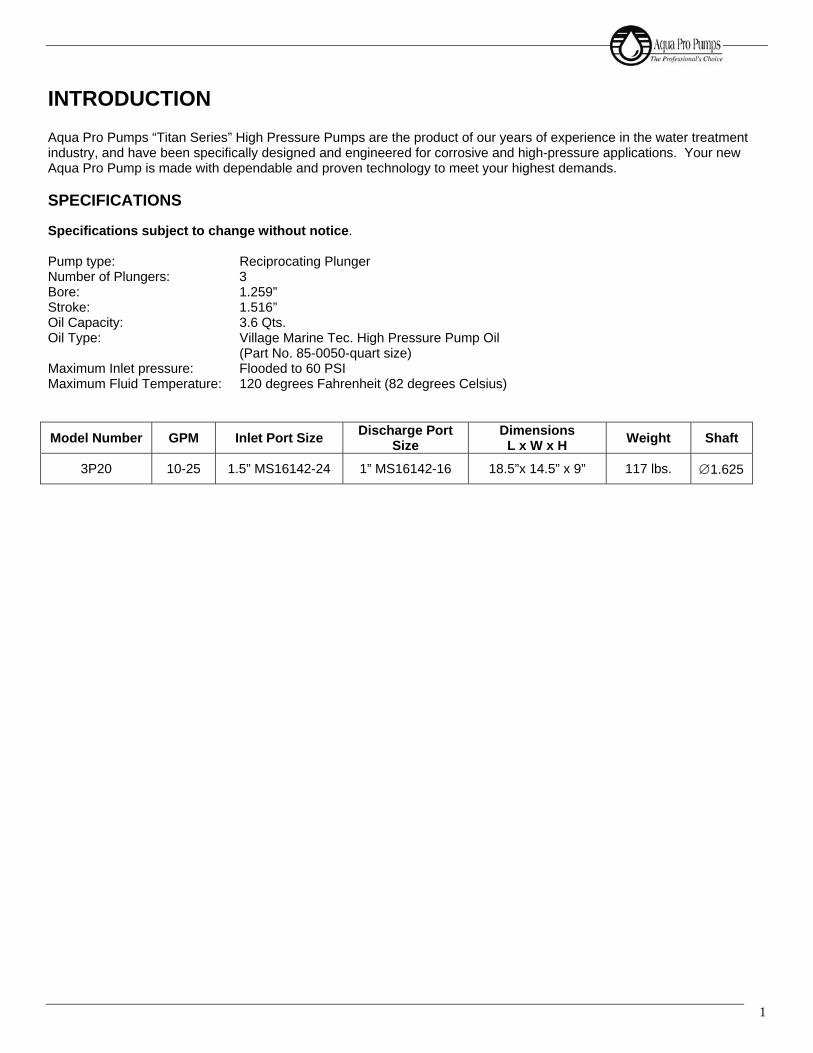
1
INTRODUCTION Aqua Pro Pumps “Titan Series” High Pressure Pumps are the product of our years of experience in the water treatment industry, and have been specifically designed and engineered for corrosive and high-pressure applications. Your new Aqua Pro Pump is made with dependable and proven technology to meet your highest demands. SPECIFICATIONS Specifications subject to change without notice. Pump type: Reciprocating Plunger Number of Plungers: 3 Bore: 1.259” Stroke: 1.516” Oil Capacity: 3.6 Qts. Oil Type: Village Marine Tec. High Pressure Pump Oil
(Part No. 85-0050-quart size) Maximum Inlet pressure: Flooded to 60 PSI Maximum Fluid Temperature: 120 degrees Fahrenheit (82 degrees Celsius)
Model Number GPM Inlet Port Size Discharge Port Size
Dimensions L x W x H Weight Shaft
3P20 10-25 1.5” MS16142-24 1” MS16142-16 18.5”x 14.5” x 9” 117 lbs. ∅1.625

3P20 Titan Series High Pressure Titanium Positive Displacement Pump
2
(2.1) RPM Desired""GPM Desired""
RPM RatedGPM Rated :RPM Pump Desired =
INITIAL START-UP INFORMATION
The performance of the pump depends on the entire fluid system and will operate best with the proper installation of plumbing, operation, and maintenance of the pump.
LUBRICATION It is recommended that pump be filled with Village Marine Tec’s specially blended high pressure pump oil. To check the oil level, ensure the pump has stopped running. Observe oil level through the sight glass in the crankcase cover. The oil should be level with the mark on the sight glass (Fig.1).
Fig. 1: Oil Level Sight Glass Detail.
PUMP FLOW DESIGN For application design purposes this pump is rated for 20 GPM at 816 RPM. To drive the pump to give the desired discharge volume for your specific application, equation 2.1 is to be used.
PULLEY SELECTION It is essential that an appropriate pulley size be selected to meet your application needs. Based on the required pump discharge volume (in GPM), the correct pulley size can be selected using equation 2.2.
WARNING
This is a positive displacement pump. A properly designed pressure relief safety valve must be installed in the discharge piping. Failure to install such a relief mechanism could result in personal injury or damage to the pump or system. Aqua Pro Pumps does not assume any liability or responsibility for the operation of a customer’s high-pressure system.
NOTE
Change the original oil in the pump after 50 hours of operation. After the initial oil change, the oil should be changed at 500-hour service intervals.
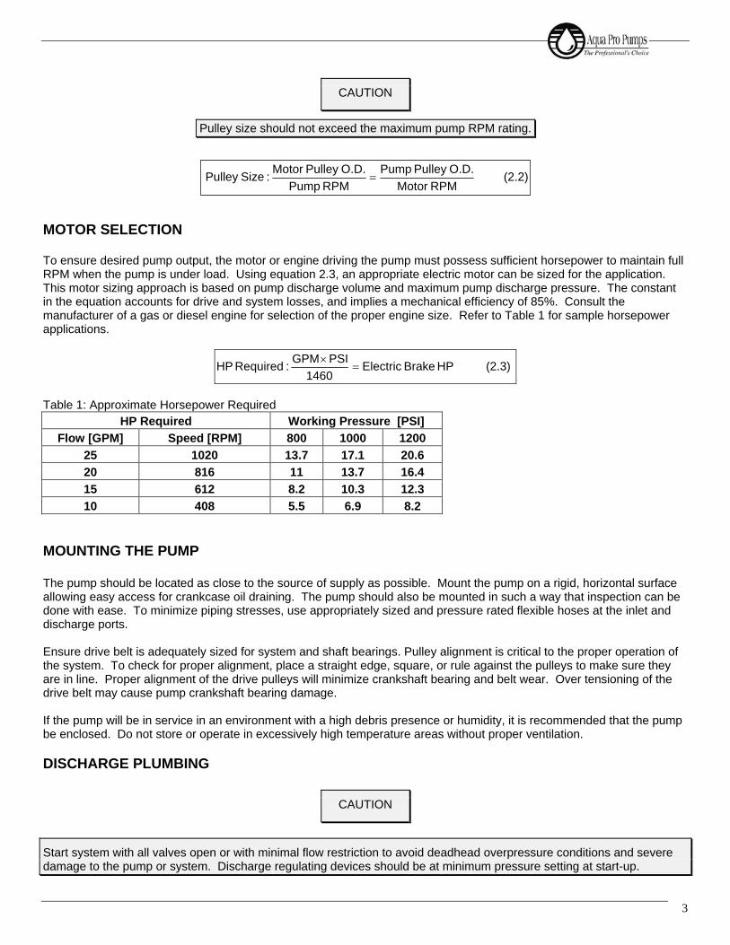
3
MOTOR SELECTION To ensure desired pump output, the motor or engine driving the pump must possess sufficient horsepower to maintain full RPM when the pump is under load. Using equation 2.3, an appropriate electric motor can be sized for the application. This motor sizing approach is based on pump discharge volume and maximum pump discharge pressure. The constant in the equation accounts for drive and system losses, and implies a mechanical efficiency of 85%. Consult the manufacturer of a gas or diesel engine for selection of the proper engine size. Refer to Table 1 for sample horsepower applications.
(2.3) HP BrakeElectric 1460
PSI GPM :Required HP =×
Table 1: Approximate Horsepower Required
HP Required Working Pressure [PSI] Flow [GPM] Speed [RPM] 800 1000 1200
25 1020 13.7 17.1 20.6 20 816 11 13.7 16.4 15 612 8.2 10.3 12.3 10 408 5.5 6.9 8.2
MOUNTING THE PUMP The pump should be located as close to the source of supply as possible. Mount the pump on a rigid, horizontal surface allowing easy access for crankcase oil draining. The pump should also be mounted in such a way that inspection can be done with ease. To minimize piping stresses, use appropriately sized and pressure rated flexible hoses at the inlet and discharge ports. Ensure drive belt is adequately sized for system and shaft bearings. Pulley alignment is critical to the proper operation of the system. To check for proper alignment, place a straight edge, square, or rule against the pulleys to make sure they are in line. Proper alignment of the drive pulleys will minimize crankshaft bearing and belt wear. Over tensioning of the drive belt may cause pump crankshaft bearing damage. If the pump will be in service in an environment with a high debris presence or humidity, it is recommended that the pump be enclosed. Do not store or operate in excessively high temperature areas without proper ventilation.
DISCHARGE PLUMBING
CAUTION
Pulley size should not exceed the maximum pump RPM rating.
CAUTION
Start system with all valves open or with minimal flow restriction to avoid deadhead overpressure conditions and severe damage to the pump or system. Discharge regulating devices should be at minimum pressure setting at start-up.
(2.2) RPM Motor
O.D.Pulley PumpRPM Pump
O.D.Pulley Motor :SizePulley =
3P20 Titan Series High Pressure Titanium Positive Displacement Pump
4
In installations utilizing a Pulsation Dampening device, the device should be mounted directly to the discharge line. Consult a dampening device manufacture for optimum pre-charge. A reliable pressure gauge should be installed near the discharge outlet of the manifold. This is extremely important for adjusting pressure-regulating devices; and when appropriate, for sizing of the nozzle or restricting orifice. The pump is rated for a maximum pressure, which is the pressure measured at the discharge manifold of the pump. A pressure relief or unloader valve must be installed to prevent over-pressure in the event the discharge or down-stream plumbing becomes restricted or is shut off. Severe damage to the pump will result if this condition occurs without a relief valve in the line.
On fittings not using o-ring seals, use PTFE liquid sparingly, or tape to connect accessories or plumbing. Do not wrap tape beyond the last thread to prevent tape from becoming lodged in the pump or accessories. This condition will cause a malfunction of the pump or system.
PUMPED FLUIDS Some fluids may require a flush between operations or before storing. For pumping fluids other than water, contact your supplier or Village Marine Tec.
STORAGE For extended storage or between uses in cold climates, drain all pumped fluids from pump and flush with antifreeze solution to prevent freezing and damage to the pump.
CAUTION
FAILURE TO INSTALL A SAFETY RELIEF VALVE WILL VOID THE WARRANTY ON THE PUMP.
CAUTION
DO NOT RUN PUMP WITH FROZEN FLUID. DO NOT RUN PUMP DRY.
5
INLET CONDITION CHECKLIST Review this checklist before operation of system. It is critical that all factors are carefully considered and met.
INLET SUPPLY Inlet supply should be adequate to accommodate the maximum flow being delivered by the pump.
1. Open inlet valve and turn on supply to avoid starving the pump.
2. Avoid closed loop systems, especially with high temperature, ultra-high pressure or large volumes. Conditions vary with regulating/unloader valve.
3. Low vapor pressure fluids, such as solvents, require positive heads to assure adequate inlet supply.
4. Higher viscosity fluids require that the pump be flooded to 60 PSI to assure adequate inlet supply.
5. Higher temperature fluids tend to vaporize and require positive heads to assure adequate inlet supply.
6. When using an inlet supply reservoir, size it to provide adequate supply of fluid to accommodate 6-10 minutes retention time at the rated GPM (however, a combination of system factors can change this requirement). Provide adequate baffling in the tank to eliminate air bubbles and turbulence. Install diffusers on all return lines to the tank.
INLET LINE SIZE Inlet line size should be adequate to avoid starving the pump. Pump suction should never operate in a vacuum.
1. Line size must be a minimum of one size larger than the pump inlet fitting. Minimize the use of thick walled fittings, tees, 90-degree elbows, or valves in the inlet line of the pump to reduce the risk of flow restriction, vacuum, and cavitation.
2. The inlet line MUST be a FLEXIBLE hose, NOT a rigid pipe, and REINFORCED ON SUCTION SYSTEMS to avoid collapsing.
3. The simpler the inlet plumbing, the less the potential for problems. It is recommended to keep the length, number of joints, and the number of inlet accessories to a minimum.
4. Use pipe sealant as appropriate to ensure airtight positive sealing pipe joints.
INLET PRESSURE Inlet pressure should be between flooded (zero) to 60 PSI.
1. High RPM, high temperatures, low vapor pressures, or high viscosity reduces inlet pressure. The pump may require a pressurized inlet to maintain adequate inlet supply.
2. Optimum pump performance and service life is obtained with 20 PSI (1.4 BAR) inlet pressure. With adequate inlet plumbing, most pumps will perform with flooded suction. Maximum inlet pressure is 60 PSI (5 BAR).
3. After prolonged storage, the pump should be purged of air to facilitate priming. With the pump shut off, disconnect the discharge port and allow fluid to pass through pump, then reconnect the discharge port.
CAUTION
DO NOT RUN PUMP DRY.

3P20 Titan Series High Pressure Titanium Positive Displacement Pump
6
INLET ACCESSORIES Inlet accessories are designed to protect against over-pressurization, to control inlet flow, contamination or temperature, and provide ease of servicing.
1. An inlet/supply shut-off valve is recommended to facilitate maintenance.
2. A standpipe can be used in some applications to help maintain a positive head in the inlet line.
3. Inspect and clean the inlet filters on a regular schedule, if applicable.
4. A vacuum/pressure gauge should be installed to monitor the inlet pressure. A gauge should be mounted as close to the pump inlet as possible. Short term, intermittent cavitation will not register on a standard gauge.
5. All accessories should be sized to avoid restricting the inlet flow.
6. All accessories should be compatible with the solution being pumped to prevent premature failure or malfunction.
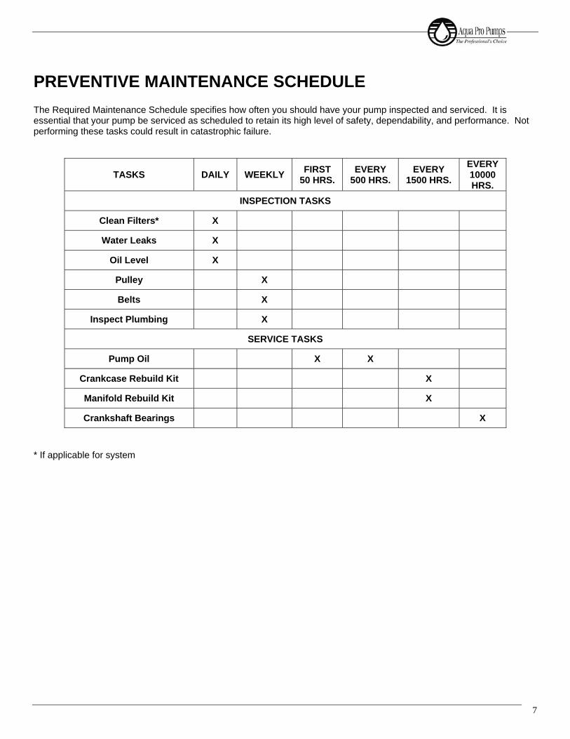
7
PREVENTIVE MAINTENANCE SCHEDULE The Required Maintenance Schedule specifies how often you should have your pump inspected and serviced. It is essential that your pump be serviced as scheduled to retain its high level of safety, dependability, and performance. Not performing these tasks could result in catastrophic failure.
TASKS DAILY WEEKLY FIRST 50 HRS.
EVERY 500 HRS.
EVERY 1500 HRS.
EVERY 10000 HRS.
INSPECTION TASKS
Clean Filters* X
Water Leaks X
Oil Level X
Pulley X
Belts X
Inspect Plumbing X
SERVICE TASKS
Pump Oil X X
Crankcase Rebuild Kit X
Manifold Rebuild Kit X
Crankshaft Bearings X * If applicable for system
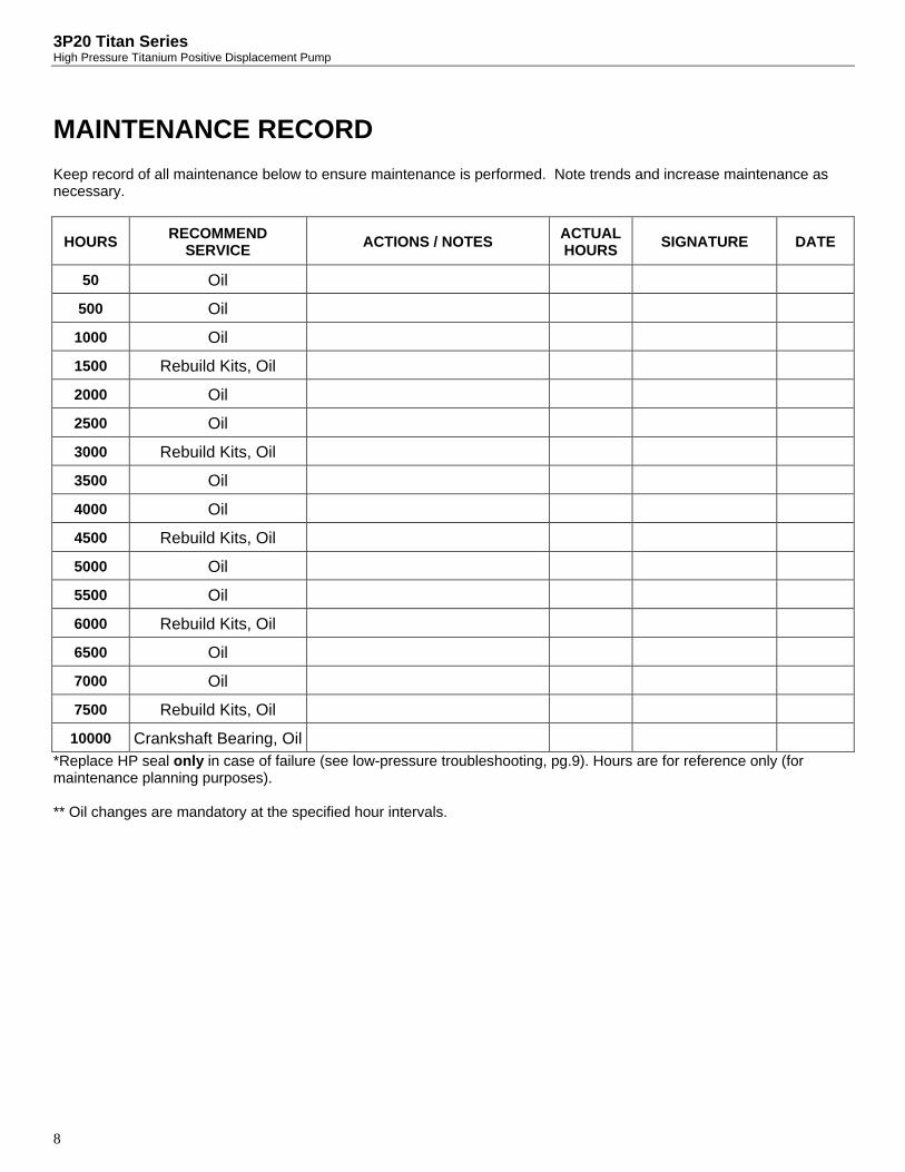
3P20 Titan Series High Pressure Titanium Positive Displacement Pump
8
MAINTENANCE RECORD Keep record of all maintenance below to ensure maintenance is performed. Note trends and increase maintenance as necessary.
HOURS RECOMMEND SERVICE ACTIONS / NOTES ACTUAL
HOURS SIGNATURE DATE
50 Oil
500 Oil
1000 Oil
1500 Rebuild Kits, Oil
2000 Oil
2500 Oil
3000 Rebuild Kits, Oil
3500 Oil
4000 Oil
4500 Rebuild Kits, Oil
5000 Oil
5500 Oil
6000 Rebuild Kits, Oil
6500 Oil
7000 Oil
7500 Rebuild Kits, Oil
10000 Crankshaft Bearing, Oil *Replace HP seal only in case of failure (see low-pressure troubleshooting, pg.9). Hours are for reference only (for maintenance planning purposes). ** Oil changes are mandatory at the specified hour intervals.
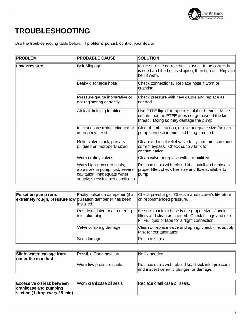
9
TROUBLESHOOTING Use the troubleshooting table below. If problems persist, contact your dealer. PROBLEM PROBABLE CAUSE SOLUTION
Low Pressure Belt Slippage Make sure the correct belt is used. If the correct belt is used and the belt is slipping, then tighten. Replace belt if worn.
Leaky discharge hose Check connections. Replace hose if worn or cracking.
Pressure gauge inoperative or not registering correctly.
Check pressure with new gauge and replace as needed.
Air leak in inlet plumbing Use PTFE liquid or tape to seal the threads. Make certain that the PTFE does not go beyond the last thread. Doing so may damage the pump.
Inlet suction strainer clogged or improperly sized
Clear the obstruction, or use adequate size for inlet pump connection and fluid being pumped.
Relief valve stuck, partially plugged or improperly sized
Clean and reset relief valve to system pressure and correct bypass. Check supply tank for contamination.
Worn or dirty valves Clean valve or replace with a rebuild kit.
Worn high-pressure seals; abrasives in pump fluid, severe cavitation; inadequate water supply; stressful inlet conditions.
Replace seals with rebuild kit. Install and maintain proper filter, check line size and flow available to pump
Pulsation pump runs extremely rough, pressure low
Faulty pulsation dampener (if a pulsation dampener has been installed.)
Check pre-charge. Check manufacturer’s literature on recommended pressure.
Restricted inlet, or air entering inlet plumbing
Be sure that inlet hose is the proper size. Check filters and clean as needed. Check fittings and use PTFE liquid or tape for airtight connection.
Valve or spring damage Clean or replace valve and spring, check inlet supply tank for contamination
Seal damage Replace seals.
Slight water leakage from under the manifold
Possible Condensation No fix needed.
Worn low pressure seals Replace seals with rebuild kit, check inlet pressure and inspect ceramic plunger for damage.
Excessive oil leak between crankcase and pumping section (1 drop every 15 min)
Worn crankcase oil seals Replace crankcase oil seals.

3P20 Titan Series High Pressure Titanium Positive Displacement Pump
10
PROBLEM PROBABLE CAUSE SOLUTION
Oil leaking from crankshaft area
Worn crankshaft oil seal Replace damaged oil seals.
Bad bearing Replace bearing.
Cut or worn o-ring on bearing case
Replace o-ring on bearing cap.
Water in crankcase Humid air condensing into water inside the crankcase
Change oil every three months or 500 hours
Worn or improperly installed crankcase oil seals
Replace seals; follow proper installation procedure.
Excessive water leaking through Low Pressure Seals
Replace seals.
Excessive play in the end of the crankshaft
Worn bearing Replace bearing.
Oil leaking in the rear portion of the crankcase
Damaged or improperly installed crankcase cover, crankcase cover o-ring, drain-plug, or drain-plug o-ring.
Replace crankcase cover o-ring or drain-plug o-ring.
Loud knocking noise in pump Pulley loose on crankshaft Check key and tighten setscrew.
Restricted Inlet Clear obstruction or replace valve.
Worn bearing, connecting rod or crankshaft.
Consult supplier for crankcase servicing.
Worn belts Replace belts.
Frequent or premature failure of the seals
Running pump dry NEVER RUN THE PUMP WITHOUT WATER.
Abrasive material in the fluid being pumped
Install proper filtration on pump inlet plumbing.
Excessive temperature of pumped fluid (120 degrees F max.)
Reduce fluid inlet temperature to specifications.
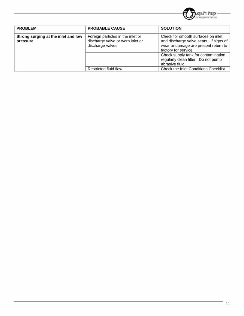
11
PROBLEM PROBABLE CAUSE SOLUTION
Strong surging at the inlet and low pressure
Foreign particles in the inlet or discharge valve or worn inlet or discharge valves
Check for smooth surfaces on inlet and discharge valve seats. If signs of wear or damage are present return to factory for service.
Check supply tank for contamination, regularly clean filter. Do not pump abrasive fluid.
Restricted fluid flow Check the Inlet Conditions Checklist.
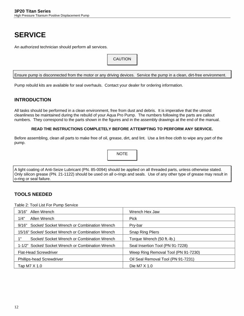
3P20 Titan Series High Pressure Titanium Positive Displacement Pump
12
SERVICE An authorized technician should perform all services.
Pump rebuild kits are available for seal overhauls. Contact your dealer for ordering information.
INTRODUCTION All tasks should be performed in a clean environment, free from dust and debris. It is imperative that the utmost cleanliness be maintained during the rebuild of your Aqua Pro Pump. The numbers following the parts are callout numbers. They correspond to the parts shown in the figures and in the assembly drawings at the end of the manual.
READ THE INSTRUCTIONS COMPLETELY BEFORE ATTEMPTING TO PERFORM ANY SERVICE. Before assembling, clean all parts to make free of oil, grease, dirt, and lint. Use a lint-free cloth to wipe any part of the pump.
TOOLS NEEDED Table 2: Tool List For Pump Service
3/16” Allen Wrench Wrench Hex Jaw
1/4” Allen Wrench Pick
9/16" Socket/ Socket Wrench or Combination Wrench Pry-bar
15/16” Socket/ Socket Wrench or Combination Wrench Snap Ring Pliers
1" Socket/ Socket Wrench or Combination Wrench Torque Wrench (50 ft.-lb.)
1-1/2” Socket/ Socket Wrench or Combination Wrench Seal Insertion Tool (PN 91-7228)
Flat-Head Screwdriver Weep Ring Removal Tool (PN 91-7230)
Phillips-head Screwdriver Oil Seal Removal Tool (PN 91-7231)
Tap M7 X 1.0 Die M7 X 1.0
CAUTION
Ensure pump is disconnected from the motor or any driving devices. Service the pump in a clean, dirt-free environment.
NOTE
A light coating of Anti-Seize Lubricant (PN. 85-0094) should be applied on all threaded parts, unless otherwise stated. Only silicon grease (PN. 21-1122) should be used on all o-rings and seals. Use of any other type of grease may result in o-ring or seal failure.

13
DETACHING THE MANIFOLD FROM THE CRANKCASE You will need these tools and parts to do the following:
15/16” Socket/ Socket Wrench or Combination Wrench Pry-bar
Remove the 2 manifold nuts (53), see Fig.13, with a 15/16” socket wrench or Combination Wrench. Loosen the manifold assembly by prying off the manifold using the slots in the crankcase as shown in Fig. 2. Set the manifold assembly aside in a clean work area. If the manifold assembly locating dowel pins (50) fall out, reinsert them into the manifold alignment pin hole.
Fig. 2: Manifold Assembly Removal
SERVICING THE CRANKCASE The following are the procedures for servicing the crankcase assembly using the 3P20 Crankcase Rebuild Kit (PN. 70-0624). The manifold assembly must be detached from the crankcase to do the following service. PLUG, OIL DRAIN, O-RING REPLACEMENT You will need these tools and parts to do the following:
1” Socket/ Socket Wrench Pick O-Ring, Drain Plug (4): PN. 30-1286 Anti-Seize Lubricant: PN. 85-0094 Silicon Grease Lubricant: PN. 21-1122
Remove the oil drain plug with a 1” wrench and drain the crankcase oil. Clean the drain plug (5), and remove the o-ring (4) with the aide of the pick if necessary. Replace the o-ring with the new one supplied with kit. Apply anti-seize lube to the threads of the drain plug (5) and reinstall. OIL SEAL REPLACEMENT You will need these tools and parts to do the following:
9/16” Socket/ Socket Wrench Torque Wrench Seal, Oil, Plunger Rod (6): PN. 70-3062 Washer, Plunger Retainer (31): PN. 70-3017 O-Ring, Plunger Retainer (30): PN. 70-3411 Ring, Back-Up, Plunger Retainer (29): PN. 70-3019 Slinger Barrier (25): PN. 70-3023 Washer, Keyhole (26): PN. 70-3022 Ceramic Lubricant: PN. 85-0087 Silicone Grease Lubricant: PN. 21-1122 Red Loctite # 262

3P20 Titan Series High Pressure Titanium Positive Displacement Pump
14
Lint-free Cloths Seal Removal Tool: PN. 91-7231
Remove the seal retainer (33) and set aside, see Fig.6. Remove the plunger retainer nut (32) with a 9/16” wrench and set aside. Remove the plunger retainer washer (31), and back-up ring(29), Fig.5, and remove the ceramic plunger (27). Remove the keyhole washer (26), then remove the slinger (25), see Fig.4. Using the seal removal tool in Fig.3, drive the screws into the plunger rod oil seal(6) and use the lanyard(provided with tool) to remove the seal from the crankcase bore. Inspect the seal retainer washers for damage; if none evident then reuse; if damage is evident consult the factory.
Fig. 3: Oil Seal Removal View
Insert new plunger rod oil seal (6) into crankcase ensuring that the seal is fully seated. Place slinger (25) onto the plunger rod (8), followed by the keyhole washer (26) as shown in Fig. 4. Chase the thread of the plunger rod and the retainer stud with the tap and die to ensure the removal of any left over loctite prior to reassembly.
Fig. 4: Plunger Assembly View
NOTE
A light coating of silicon grease (PN. 21-1122) should be used on all new o-rings and seals. Use of any other type of grease may result in o-ring or seal failure.
NOTE
Examine the ceramic plungers (27), Fig. 6, for cracks, heavy scoring, or unusual wear. If there is a problem, contact the factory.
25
8
6
26
Seal Removal Tool
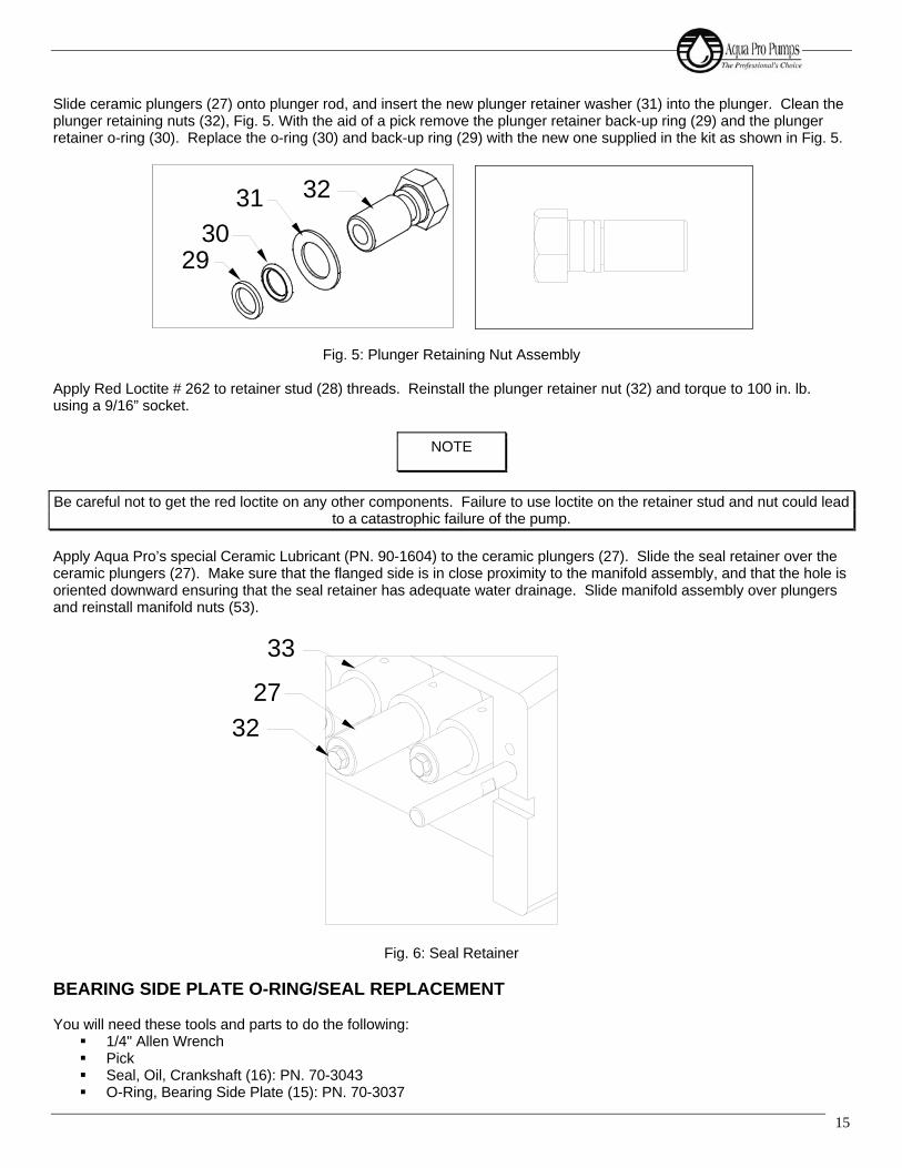
15
Slide ceramic plungers (27) onto plunger rod, and insert the new plunger retainer washer (31) into the plunger. Clean the plunger retaining nuts (32), Fig. 5. With the aid of a pick remove the plunger retainer back-up ring (29) and the plunger retainer o-ring (30). Replace the o-ring (30) and back-up ring (29) with the new one supplied in the kit as shown in Fig. 5.
Fig. 5: Plunger Retaining Nut Assembly Apply Red Loctite # 262 to retainer stud (28) threads. Reinstall the plunger retainer nut (32) and torque to 100 in. lb. using a 9/16” socket.
Apply Aqua Pro’s special Ceramic Lubricant (PN. 90-1604) to the ceramic plungers (27). Slide the seal retainer over the ceramic plungers (27). Make sure that the flanged side is in close proximity to the manifold assembly, and that the hole is oriented downward ensuring that the seal retainer has adequate water drainage. Slide manifold assembly over plungers and reinstall manifold nuts (53).
Fig. 6: Seal Retainer BEARING SIDE PLATE O-RING/SEAL REPLACEMENT You will need these tools and parts to do the following:
1/4" Allen Wrench Pick Seal, Oil, Crankshaft (16): PN. 70-3043 O-Ring, Bearing Side Plate (15): PN. 70-3037
NOTE
Be careful not to get the red loctite on any other components. Failure to use loctite on the retainer stud and nut could lead to a catastrophic failure of the pump.
31
2930
32
33
27
32
3P20 Titan Series High Pressure Titanium Positive Displacement Pump
16
Silicon Grease Lubricant: PN. 21-1122 Anti-Seize Lubricant: PN. 85-0094
Remove the 4 socket head cap screws (17) with a 1/4” Allen Wrench from each of bearing side plate (13), (14). With the aide of a pick remove the o-rings from the grooves and remove the crankshaft oil seal (16) from the pulley side bearing cap (14).
Press new crankshaft oil seal (16) into pulley side bearing cap (14), install o-ring (15) in o-ring groove on the crankshaft bearing caps (13) and (14), and reinstall caps on pump.
Install the 4 socket head cap screws (17) onto each of the bearing side plates and tighten with a 1/4” Allen Wrench. COVER, CRANKCASE O-RING REPLACEMENT In this procedure you will replace the o-rings on the crankcase cover as provided in the rebuild kit. You will need these tools and parts to do the following:
3/16” Allen Wrench Phillips-head Screwdriver Pick Silicone Grease Lubricant: PN. 21-1122 Red Loctite # 262 Anti-Seize Lubricant: PN. 85-0094
Unscrew the 10 crankcase cover screws (24) with the 3/16” Allen wrench. Remove the 6 sight glass retaining screws (23) with the Phillips-head screwdriver. Remove the sight glass retaining frame (22) and the sight glass (21). With the aide of the pick remove the sight glass o-ring (20), and remove the crankcase cover o-ring (18).
Install the new sight glass o-ring (20) and the crankcase cover o-ring (18) provided with the rebuild kit.
CAUTION
Crankshaft oil seal is press fit at the factory, so care is to be exercised during removal to prevent any damage to sealing surface.
NOTE
A light coating of silicon grease (PN. 21-1122) should be used on all new o-rings and seals. Use of any other type of grease may result in o-ring or seal failure.
NOTE
A light coating of Anti-Seize Lubricant (PN. 85-0094) should be applied on all threaded parts, unless otherwise stated.
NOTE
A light coating of silicon grease (PN. 21-1122) should be used on all new o-rings and seals. Use of any other type of grease may result in o-ring or seal failure.
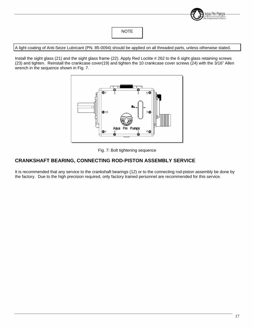
17
Install the sight glass (21) and the sight glass frame (22). Apply Red Loctite # 262 to the 6 sight glass retaining screws (23) and tighten. Reinstall the crankcase cover(19) and tighten the 10 crankcase cover screws (24) with the 3/16” Allen wrench in the sequence shown in Fig. 7.
Fig. 7: Bolt tightening sequence
CRANKSHAFT BEARING, CONNECTING ROD-PISTON ASSEMBLY SERVICE It is recommended that any service to the crankshaft bearings (12) or to the connecting rod-piston assembly be done by the factory. Due to the high precision required, only factory trained personnel are recommended for this service.
NOTE
A light coating of Anti-Seize Lubricant (PN. 85-0094) should be applied on all threaded parts, unless otherwise stated.
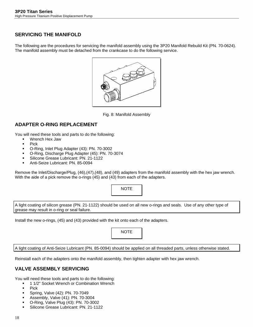
3P20 Titan Series High Pressure Titanium Positive Displacement Pump
18
SERVICING THE MANIFOLD The following are the procedures for servicing the manifold assembly using the 3P20 Manifold Rebuild Kit (PN. 70-0624). The manifold assembly must be detached from the crankcase to do the following service.
Fig. 8: Manifold Assembly ADAPTER O-RING REPLACEMENT You will need these tools and parts to do the following:
Wrench Hex Jaw Pick O-Ring, Inlet Plug Adapter (43): PN. 70-3002 O-Ring, Discharge Plug Adapter (45): PN. 70-3074 Silicone Grease Lubricant: PN. 21-1122 Anti-Seize Lubricant: PN. 85-0094
Remove the Inlet/Discharge/Plug, (46),(47),(48), and (49) adapters from the manifold assembly with the hex jaw wrench. With the aide of a pick remove the o-rings (45) and (43) from each of the adapters.
Install the new o-rings, (45) and (43) provided with the kit onto each of the adapters.
Reinstall each of the adapters onto the manifold assembly, then tighten adapter with hex jaw wrench. VALVE ASSEMBLY SERVICING You will need these tools and parts to do the following:
1 1/2" Socket Wrench or Combination Wrench Pick Spring, Valve (42): PN. 70-7049 Assembly, Valve (41): PN. 70-3004 O-Ring, Valve Plug (43): PN. 70-3002 Silicone Grease Lubricant: PN. 21-1122
NOTE
A light coating of silicon grease (PN. 21-1122) should be used on all new o-rings and seals. Use of any other type of grease may result in o-ring or seal failure.
NOTE
A light coating of Anti-Seize Lubricant (PN. 85-0094) should be applied on all threaded parts, unless otherwise stated.

19
Anti-Seize Lubricant: PN. 85-0094 Lint-Free Cloths
If manifold assembly has been removed from the crankcase assembly, place the assembly on a clean work surface. Remove all of the valve plug assemblies from the manifold assembly using a 1 1/2” socket wrench or combination wrench. Remove the valve (41) from the assembly, followed by the valve spring (42). With the aide of a pick remove the o-ring (43) from the valve plug.
Clean and inspect all valve plugs (44) prior to reassembly. If there is a problem, contact your dealer. Once all valve plugs (44) are clean and dry, install new valve plug o-ring (43) onto valve plug (44). Install the valve spring (42) onto the valve plug (44). Press the valve (41) onto the valve spring (42). Complete valve assembly shown in Fig. 9.
Fig. 9: Valve Assembly
Inspect the manifold (34) for debris or other fouling and clean if necessary. Inspect the valve seat surface in the manifold. If there is a problem, contact your dealer. Reinstall all the valve plug assemblies with a 1 1/2" socket wrench or combination wrench and tighten.
NOTE
Valves may be serviced while the manifold assembly is attached to the crankcase assembly.
NOTE
Valve plugs (44) will be reused.
A light coating of silicon grease (PN. 21-1122) should be used on all new o-rings and seals. Use of any other type of grease may result in o-ring or seal failure.
NOTE
A light coating of Anti-Seize Lubricant (PN. 85-0094) should be applied on all threaded parts, unless otherwise stated.
44
43
4241

3P20 Titan Series High Pressure Titanium Positive Displacement Pump
20
MANIFOLD SEAL SERVICING
You will need these tools and parts to do the following:
Snap Ring Pliers Tool, Weep Ring Extractor: PN. 91-7230 Tool, Seal Insertion: PN. 91-7228 Flat screw driver Seal, HP (36): PN. 70-2502 Ring, Snap (38): PN. 70-3009 Ring, Weep (37): PN. 70-3008 Seal, LP (40): PN. 70-2501 Silicone Grease Lubricant: PN. 21-1122 Lint-Free Cloths
For manifold seal servicing purposes the manifold must be placed with the valve plugs sitting on a flat surface and the plunger bores facing upward. This will facilitate service technician access to the seals for removal and installation, as shown in Fig. 10.
Fig. 10: Orientation for Manifold Seal Servicing With a flat screw driver remove the low-pressure seal (40). Manually remove the low-pressure seal spacer (39). With the snap ring pliers remove the snap ring (38). Using the weep ring extracting tool, remove the weep ring (37) as shown in Fig. 11.
NOTE
Pump manifold assembly must be detached from the crankcase assembly to service the seals.
NOTE
Extraction of the rings is accomplished by inserting tool in relaxed state into the inner diameter of the rings, then tightening the expansion bolt to grip the ring.

21
Fig. 11: Weep Ring Extraction With a flat screwdriver remove the high-pressure seals (36). Manually remove the high-pressure seal spacer (35). You must clean and inspect the following parts for re-use:
• Spacer, High-Pressure Seal (35): PN. 70-0407 • Spacer, Low-Pressure Seal (39): PN. 70-3010
Insert the high-pressure seal spacer (35) into the bore.
Insert the high-pressure seal (36) into the bore until the seal is fully seated on the high-pressure seal spacer (35), using the seal insertion tool. See Fig. 12 for high-pressure seal installation view.
Fig. 12: High-Pressure Seals Installation View Insert the weep ring (37) into the bore after the installation of the high-pressure seals (36), using the driver from the seal insertion tool. Install the snap ring (38) using the snap ring pliers.
NOTE
A light coating of silicon grease (PN. 21-1122) should be used on all new o-rings and seals. Use of any other type of grease may result in o-ring or seal failure.
NOTE
Ensure that the snap ring (38) is fully seated in the snap ring groove before continuing.
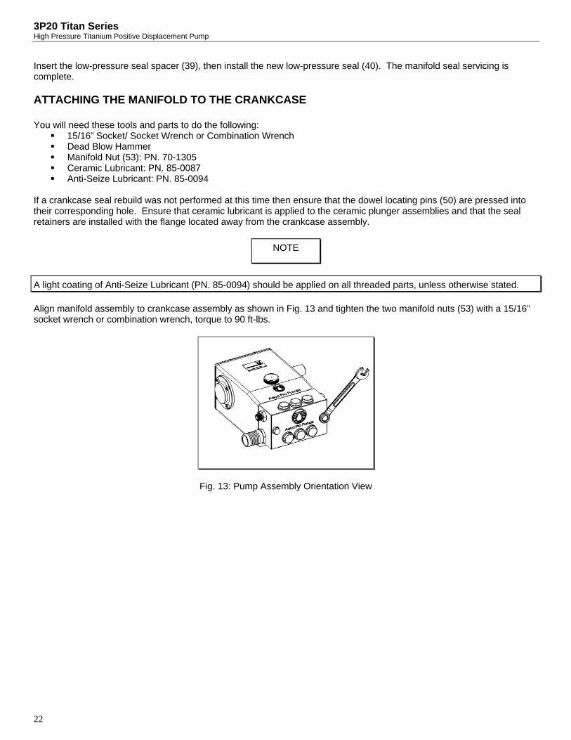
3P20 Titan Series High Pressure Titanium Positive Displacement Pump
22
Insert the low-pressure seal spacer (39), then install the new low-pressure seal (40). The manifold seal servicing is complete.
ATTACHING THE MANIFOLD TO THE CRANKCASE You will need these tools and parts to do the following:
15/16” Socket/ Socket Wrench or Combination Wrench Dead Blow Hammer Manifold Nut (53): PN. 70-1305 Ceramic Lubricant: PN. 85-0087 Anti-Seize Lubricant: PN. 85-0094
If a crankcase seal rebuild was not performed at this time then ensure that the dowel locating pins (50) are pressed into their corresponding hole. Ensure that ceramic lubricant is applied to the ceramic plunger assemblies and that the seal retainers are installed with the flange located away from the crankcase assembly.
Align manifold assembly to crankcase assembly as shown in Fig. 13 and tighten the two manifold nuts (53) with a 15/16” socket wrench or combination wrench, torque to 90 ft-lbs.
Fig. 13: Pump Assembly Orientation View
NOTE
A light coating of Anti-Seize Lubricant (PN. 85-0094) should be applied on all threaded parts, unless otherwise stated.
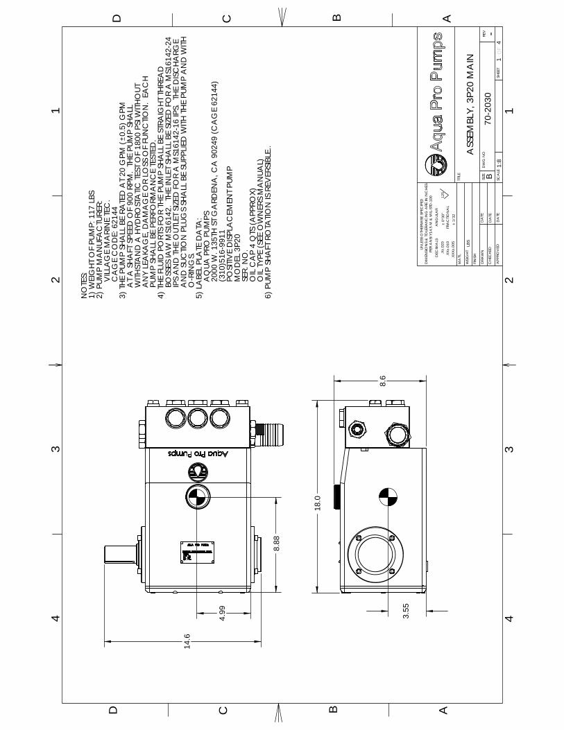
8.88
4.99 3.55
14.6
18.0
8.6
NO
TES:
1) W
EIG
HT
OF
PUM
P: 1
17 L
BS2)
PUM
P M
AN
UFA
CTU
RER:
VIL
LAG
E M
ARI
NE
TEC
.C
AG
E C
OD
E: 6
2144
3) T
HE
PUM
P SH
ALL
BE
RATE
D A
T 20
GPM
(0.
5) G
PM
AT
A S
HA
FT S
PEED
OF
900
RPM
. TH
E PU
MP
SHA
LL
WITH
STA
ND
A H
YDRO
STA
TIC T
EST
OF
1800
PSI
WITH
OUT
A
NY
LEA
KAG
E, D
AM
AG
E O
R LO
SS O
F FU
NC
TION
. EA
CH
P
UMP
SHA
LL B
E PE
RFO
RMA
NC
E TE
STED
.4)
TH
E FL
UID
PO
RTS
FOR
THE
PUM
P SH
ALL
BE
STRA
IGH
T TH
REA
D
BO
SSES
IAW
MS1
6142
. TH
E IN
LET
SHA
LL B
E SI
ZED
FO
R A
MS1
6142
-24
I
PS A
ND
TH
E O
UTLE
T SI
ZED
FO
R A
MS1
6142
-16
IPS.
TH
E D
ISC
HA
RGE
A
ND
SUC
TION
PLU
GS
SHA
LL B
E SU
PPLI
ED W
ITH T
HE
PUM
P A
ND
WITH
O
-RIN
GS.
5) L
ABE
L PL
ATE
DA
TA:
AQ
UA P
RO P
UMPS
2000
W. 1
35TH
ST
GA
RDEN
A, C
A 9
0249
(CA
GE
6214
4)(3
10)5
16-9
911
POSI
TIVE
DIS
PLA
CEM
ENT
PUM
PM
OD
EL 3
P20
SER.
NO
.O
IL C
AP
4 Q
TS (A
PPRO
X)O
IL T
YPE
(SEE
OW
NER
S M
AN
UAL)
6) P
UMP
SHA
FT R
OTA
TION
IS R
EVER
SIBL
E..
43
REV
OF
SHEE
T
125
.X±.
020
DEC
IMA
LS
DIM
ENSI
ON
S &
TO
LERA
NC
ING
ARE
IN IN
CH
ESPE
R A
NSI
Y14
.5 M
& M
IL-S
TD-1
00A
NG
ULA
R
± 0°
30"
UN
LESS
OTH
ERW
ISE
SPEC
IFED
TITL
E
SIZE
SCA
LE
B
WEI
GH
T
DRA
WN
FIN
ISH.X
X±.0
10.X
XX±.
005
MA
T'L
APP
ROV
ED
CH
ECKE
D
DA
TE
DA
TE
DA
TE
± 1/
32FR
AC
TIO
NA
L
DW
G N
O
LBS
41
1:8
-70
-203
0
ASS
EMBL
Y, 3
P20
MA
IN
32
14
D C B AAD C B
21
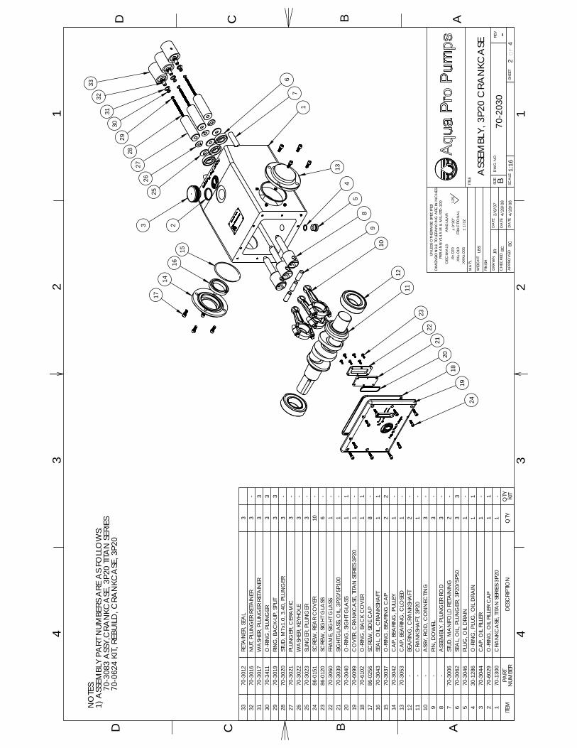
1
REV
OF
SHEE
T
125
.X±.
020
DEC
IMA
LS
DIM
ENSI
ON
S &
TO
LERA
NC
ING
ARE
IN IN
CH
ESPE
R A
NSI
Y14
.5 M
& M
IL-S
TD-1
00A
NG
ULA
R
± 0°
30"
UN
LESS
OTH
ERW
ISE
SPEC
IFED
TITL
E
SIZE
SCA
LE
B
WEI
GH
T
DRA
WN
FIN
ISH.X
X±.0
10.X
XX±.
005
MA
T'L
APP
ROV
ED
CH
ECKE
D
DA
TE
DA
TE
DA
TE
± 1/
32FR
AC
TIO
NA
L
DW
G N
O
BC
2/6/
07JR L
BS
42
1:16
-70
-203
0
ASS
EMBL
Y, 3
P20
CRA
NKC
ASE
4/28
/08
4/28
/08
32
14
D C B AAD C B
24
3BC
28
1416
152
1
2930
31
263
27
33
25
67
13
17
5
9
2322
21
1924
1112
2018
10
8
4
32
70-0
624
KIT,
REB
UILD
, CRA
NKC
ASE
, 3P2
070
-308
3 A
SSY,
CRA
NKC
ASE
, 3P2
0 TIT
AN
SER
IES
1) A
SSEM
BLY
PART
NUM
BERS
ARE
AS
FOLL
OW
S:N
OTE
S:
ITEM
PART
N
UMBE
RD
ESC
RIPT
ION
QTY
QTY
KI
T
3370
-301
2RE
TAIN
ER, S
EAL
332
70-3
016
NUT
, PLU
NG
ER R
ETA
INER
3-
3170
-301
7W
ASH
ER, P
LUN
GER
RET
AIN
ER3
330
70-3
411
O-R
ING
, PLU
NG
ER3
329
70-3
019
RIN
G, B
AC
K-UP
, SPL
IT3
328
70-3
020
STUD
, M7x
1.0,
3.4
0, P
LUN
GER
3-
2770
-302
1PL
UNG
ER, C
ERA
MIC
3-
2670
-302
2W
ASH
ER, K
EYHO
LE3
-25
70-3
023
SLIN
GER
, PLU
NG
ER3
-24
86-0
151
SCRE
W, R
EAR
CO
VER
10-
2386
-012
0SC
REW
, SIG
HT G
LASS
6-
2270
-306
0FR
AM
E, S
IGHT
GLA
SS1
-21
70-3
039
SIG
HTG
LASS
, OIL,
3P2
0/5P
100
1-
2070
-304
0O
-RIN
G, S
IGHT
GLA
SS1
119
70-6
099
CO
VER
, CRA
NKC
ASE
, TITA
N S
ERIE
S 3P
201
-18
70-6
102
O-R
ING
, BA
CK
CO
VER
11
1786
-025
6SC
REW
, SID
E C
AP
8-
1670
-304
3SE
AL,
OIL,
CRA
NKS
HAFT
11
1570
-303
7O
-RIN
G, B
EARI
NG
CA
P2
214
70-3
042
CA
P, B
EARI
NG
, PUL
LEY
1-
1370
-305
3C
AP,
BEA
RIN
G, C
LOSE
D1
-12
-BE
ARI
NG
, CRA
NKS
HAFT
2-
11-
CRA
NKS
HAFT
, 3P2
01
-10
-A
SSY,
RO
D, C
ON
NEC
TING
3-
9-
PIN
, DO
WEL
3-
8-
ASS
EMBL
Y, P
LUN
GER
RO
D3
-7
70-3
006
STUD
, MA
NIFO
LD R
ETA
ININ
G2
-6
70-3
062
SEA
L, O
IL, P
LUN
GER
, 3P2
0/5P
503
35
70-3
046
PLUG
, OIL
DRA
IN1
-4
30-1
286
O-R
ING
, PLU
G, O
IL D
RAIN
11
370
-304
4C
AP,
OIL
FILLE
R1
-2
70-6
029
O-R
ING
, OIL
FILLE
R C
AP
11
170
-130
0C
RAN
KCA
SE, T
ITAN
SER
IES
3P20
1-

ITEM
PART
N
UMBE
RD
ESC
RIPT
ION
QTY
QTY
KI
T
5070
-305
0PI
N, D
OW
EL2
-49
70-3
066
PLUG
,MS1
8229
-16,
TI1
-48
70-3
065
PLUG
,MS1
8829
-24,
TI1
-47
70-3
059
AD
TR, F
AC
E SE
AL
1-
4670
-306
4A
DTR
, 2.0
HB,
MS1
8229
-24
1-
4570
-307
4O
-RIN
G, A
PTR,
INLE
T2
244
70-3
001
PLUG
, VA
LVE,
MS1
8229
-16
6-
4370
-300
2O
-RIN
G, V
ALV
E8
842
70-7
049
SPRI
NG
, VA
LVE,
3P2
0/5P
506
641
70-3
004
VA
LVE,
PUM
P,3P
20/5
P50
66
4070
-250
1SE
AL,
LO
W P
RESS
URE
33
3970
-301
0SP
AC
ER, L
OW
PRE
SSUR
E SE
AL
33
3870
-300
9RI
NG
, RET
AIN
ING
, 3P2
0/5P
503
337
70-3
008
ASS
EMBL
Y, W
EEP
RIN
G,3
P20/
5P50
33
3670
-250
2SE
AL,
HIG
H PR
ESSU
RE3
335
70-0
407
RIN
G, S
PAC
ER, H
P SE
AL
33
3470
-130
1M
AN
IFO
LD, T
ITAN
SER
IES
3P20
1-
REV
OF
SHEE
T
125
.X±.
020
DEC
IMA
LS
DIM
ENSI
ON
S &
TO
LERA
NC
ING
ARE
IN IN
CH
ESPE
R A
NSI
Y14
.5 M
& M
IL-S
TD-1
00A
NG
ULA
R
± 0°
30"
UN
LESS
OTH
ERW
ISE
SPEC
IFED
TITL
E
SIZE
SCA
LE
B
WEI
GH
T
DRA
WN
FIN
ISH.X
X±.0
10.X
XX±.
005
MA
T'L
APP
ROV
ED
CH
ECKE
D
DA
TE
DA
TE
DA
TE
± 1/
32FR
AC
TIO
NA
L
DW
G N
O
LBS
43
1:12
-70
-203
0
ASS
EMBL
Y, 3
P20
MA
NIF
OLD
32
14
D C B AAD C B
24
31
42
44
43
41 47
46
34
35
50
37
36
38
39
40
48
49
45
NO
TES:
1) A
SSEM
BLY
PART
NUM
BERS
ARE
AS
FOLL
OW
S:70
-612
2 A
SSY,
MA
NIF
OLD
, 3P2
0 TIT
AN
SER
IES
70-0
623
KIT,
REB
UILD
, MA
NIF
OLD
, 3P2
0
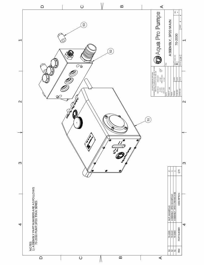
D C B AAD C B
24
3
REV
OF
SHEE
T
125
.X±.
020
DEC
IMA
LS
DIM
ENSI
ON
S &
TO
LERA
NC
ING
ARE
IN IN
CH
ESPE
R A
NSI
Y14
.5 M
& M
IL-S
TD-1
00A
NG
ULA
R
± 0°
30"
UN
LESS
OTH
ERW
ISE
SPEC
IFED
TITL
E
SIZE
SCA
LE
B
WEI
GH
T
DRA
WN
FIN
ISH.X
X±.0
10.X
XX±.
005
MA
T'L
APP
ROV
ED
CH
ECKE
D
DA
TE
DA
TE
DA
TE
± 1/
32FR
AC
TIO
NA
L
DW
G N
O
LBS
44
1:16
-70
-203
0
ASS
EMBL
Y, 3
P20
MA
IN
32
14
1
70-2
030
PUM
P,3P
20 T
ITAN
SER
IES
1) A
SSEM
BLY
PART
NUM
BERS
ARE
AS
FOLL
OW
S:N
OTE
S:
ITEM
PART
NUM
BER
DES
CRI
PTIO
NQ
TY.
5370
-130
5N
UT, M
AN
IFOLD
252
70-6
122
ASS
EMBL
Y, 3
P20
MA
NIFO
LD1
5170
-308
3A
SSEM
BLY,
3P2
0 C
RAN
KCA
SE1
52
51
53
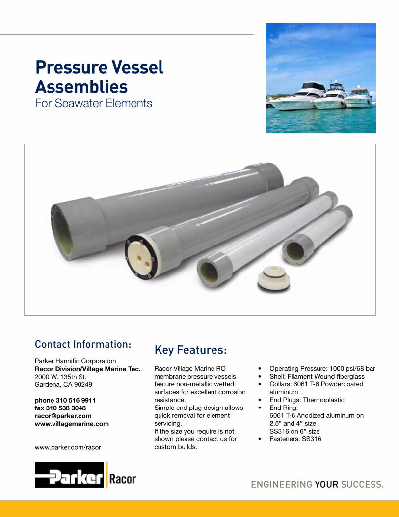
Racor Village Marine RO membrane pressure vessels feature non-metallic wetted surfaces for excellent corrosion resistance.Simple end plug design allows quick removal for element servicing.If the size you require is not shown please contact us for custom builds.
Pressure Vessel Assemblies
Contact Information:Parker Hannifin CorporationRacor Division/Village Marine Tec.2000 W. 135th St.Gardena, CA 90249
phone 310 516 9911fax 310 538 [email protected]
www.parker.com/racor
Key Features:• Operating Pressure: 1000 psi/68 bar• Shell: Filament Wound fiberglass• Collars: 6061 T-6 Powdercoated
aluminum• End Plugs: Thermoplastic• End Ring:
6061 T-6 Anodized aluminum on 2.5” and 4” sizeSS316 on 6” size
• Fasteners: SS316
For Seawater Elements
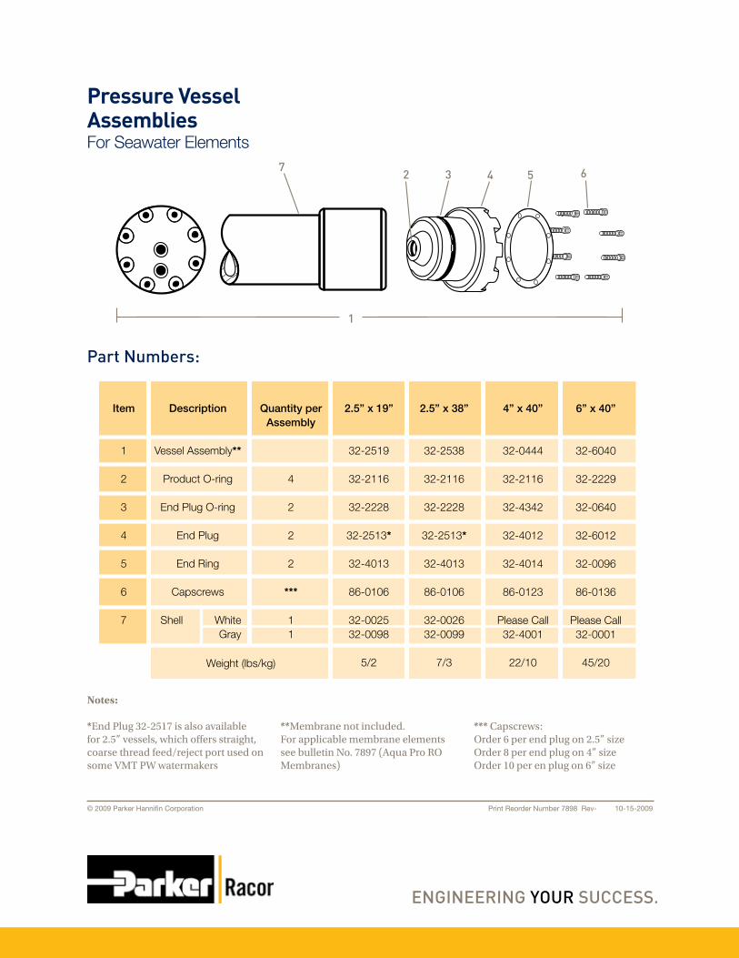
Description
Vessel Assembly**
Product O-ring
End Plug O-ring
End Plug
End Ring
Capscrews
Shell WhiteGray
Item
1
2
3
4
5
6
7
Quantity per Assembly
4
2
2
2
***
11
2.5” x 19”
32-2519
32-2116
32-2228
32-2513*
32-4013
86-0106
32-002532-0098
5/2
2.5” x 38”
32-2538
32-2116
32-2228
32-2513*
32-4013
86-0106
32-002632-0099
7/3
4” x 40”
32-0444
32-2116
32-4342
32-4012
32-4014
86-0123
Please Call32-4001
22/10
6” x 40”
32-6040
32-2229
32-0640
32-6012
32-0096
86-0136
Please Call32-0001
45/20Weight (lbs/kg)
Notes:
*End Plug 32-2517 is also available for 2.5” vessels, which offers straight, coarse thread feed/reject port used on some VMT PW watermakers
**Membrane not included.For applicable membrane elements see bulletin No. 7897 (Aqua Pro RO Membranes)
*** Capscrews: Order 6 per end plug on 2.5” sizeOrder 8 per end plug on 4” sizeOrder 10 per en plug on 6” size
Print Reorder Number 7898 Rev- 10-15-2009© 2009 Parker Hannifin Corporation
Pressure Vessel AssembliesFor Seawater Elements
Part Numbers:
1
2 3 4 5 67

Aqua Pro® Sea WaterRO Membranes
Contact Information:Parker Hannifin CorporationRacor Division/Village Marine Tec.2000 W. 135th St.Gardena, CA 90249
phone 310 516 9911fax 310 538 [email protected]
www.parker.com/racor
Aqua Pro® thin film composite membranes deliver high salt rejection while maintaining high production rates to obtain the energy efficiency demanded by plant operators.
By selecting the highest grade of materials and thoroughly testing performance, Racor Village Marine is able to offer the highest quality Aqua Pro® products.
Key Feature:
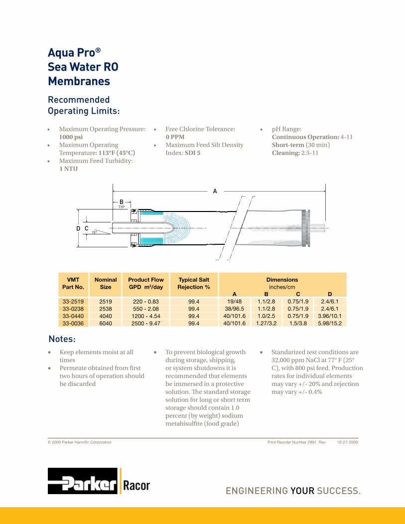
• MaximumOperatingPressure:1000 psi
• MaximumOperatingTemperature:113°F (45°C)
• MaximumFeedTurbidity:1 NTU
• FreeChlorineTolerance:0 PPM• MaximumFeedSiltDensity
Index:SDI 5
• pHRange: Continuous Operation:4-11 Short-term(30min) Cleaning:2.5-11
Print Reorder Number 7897 Rev- 10-27-2009© 2009 Parker Hannifin Corporation
Aqua Pro®
Sea Water RO Membranes
Notes:
RecommendedOperating Limits:
A
BTYP
CD15°
Nominal Size
2519253840406040
Product FlowGPD m3/day
220 - 0.83550 - 2.08
1200 - 4.542500 - 9.47
Typical SaltRejection %
99.499.499.499.4
VMTPart No.
33-251933-023833-044033-0036
Dimensionsinches/cm
A19/48
38/96.540/101.640/101.6
B1.1/2.81.1/2.81.0/2.5
1.27/3.2
C0.75/1.90.75/1.90.75/1.91.5/3.8
D2.4/6.12.4/6.1
3.96/10.15.98/15.2
• Keepelementsmoistatalltimes
• Permeateobtainedfromfirsttwohoursofoperationshouldbediscarded
• Topreventbiologicalgrowthduringstorage,shipping,orsystemshutdownsitisrecommendedthatelementsbeimmersedinaprotectivesolution.Thestandardstoragesolutionforlongorshorttermstorageshouldcontain1.0percent(byweight)sodiummetabisulfite(foodgrade)
• Standarizedtestconditionsare32,000ppmNaClat77°F(25°C),with800psifeed.Productionratesforindividualelementsmayvary+/-20%andrejectionmayvary+/-0.4%

Filter HousingsFRP Shell with Nylon Caps100X-FRP
Contact Information:Parker Hannifin CorporationRacor Division/Village Marine Tec.2000 W. 135th St.Gardena, CA 90249
phone: 310 516-9911 800 C-Parkerfax: 310 538-3048email: [email protected]
www.parker.com/racor
Racor Village Marine offers fiberglass filter housings specifically designed for seawater use. Simple but secure closure systems allow quick cartridge change. Aluminum collars are bonded to fiberglass shells offer superior corrosion resistance. The base and lid are nylon.
The housings fit VMT pleated cartridge elements of 100 square feet area. Available in 0.5, 1, 5, 20, and 100 micron ratings.

Filter HousingsFRP Shell with Nylon Caps100X-FRP
DWG
1
2
3
4
5
6
7
8
9
Part Number
30-4353
M4353-4
M1157-1
M4353-2
30-0405
86-0022
86-0264
86-0006
86-0269
86-0260
Description
Filter Assembly
Vessel Shell
Base
Lid
O-Ring
Nuts - Bottom
Studs
Washer
Wingnut
Bolt - Bottom
Specifications
Design Pressure* 80 psi
Test Pressure 120 psi
Inlet 1.5” FPT
Outlet 1.5” FPT
Height 33”/84 cm
Diameter 13”/33 cm
© 2011 Parker Hannifin Corporation
To maintain peak performance always use genuine Parker Racor Village Marine replacement parts.We reserve the right to change our specifications or standards without notice.
*Filter Housing Vessel is designed in accordance with ASME section x pressure vessel code.
Print Reorder Number 7940 Rev-B 09-26-2011
8 Req’d
8 Req’d
8 Req’d
2 Req’d
8 Req’d
8 Req’d

The Village Marine Tec. line of pleated filters are designed specifically for the RO watermaker industry and are superior to wound or polyspun cartridges to give you a longer filter life as well as increasing flow rates and keeping cartridge size down.
Available in a wide arrange of sizes and micron ranges to ensure that every type of watermaker filter need is taken care of. Stock sizes fit most standard filter housings, if the size you need is not shown please contact us with the dimensions required.
Pleated Filters and Filter Cartridge Kits
Contact Information:Parker Hannifin CorporationRacor Division/Village Marine Tec.2000 W. 135th St.Gardena, CA 90249
phone: 310 516-9911 800 C-Parkerfax: 310 538-3048email: [email protected]
www.parker.com/racor
Single use Cleaning and Preservative Cartridge Kits are designed specifically for small RO Systems. The Cartridges allow for easy and effective membrane maintenance.
The Cleaning and Preservative Cartridge Kits eliminate the trouble and mess of measuring powdered chemicals and ensuring correct chemical concentrations. The Chemical cartridges fit directly into 2.5” x 10” or 4.5” x 10” housings and contain the correct amount of chemical for a single use.
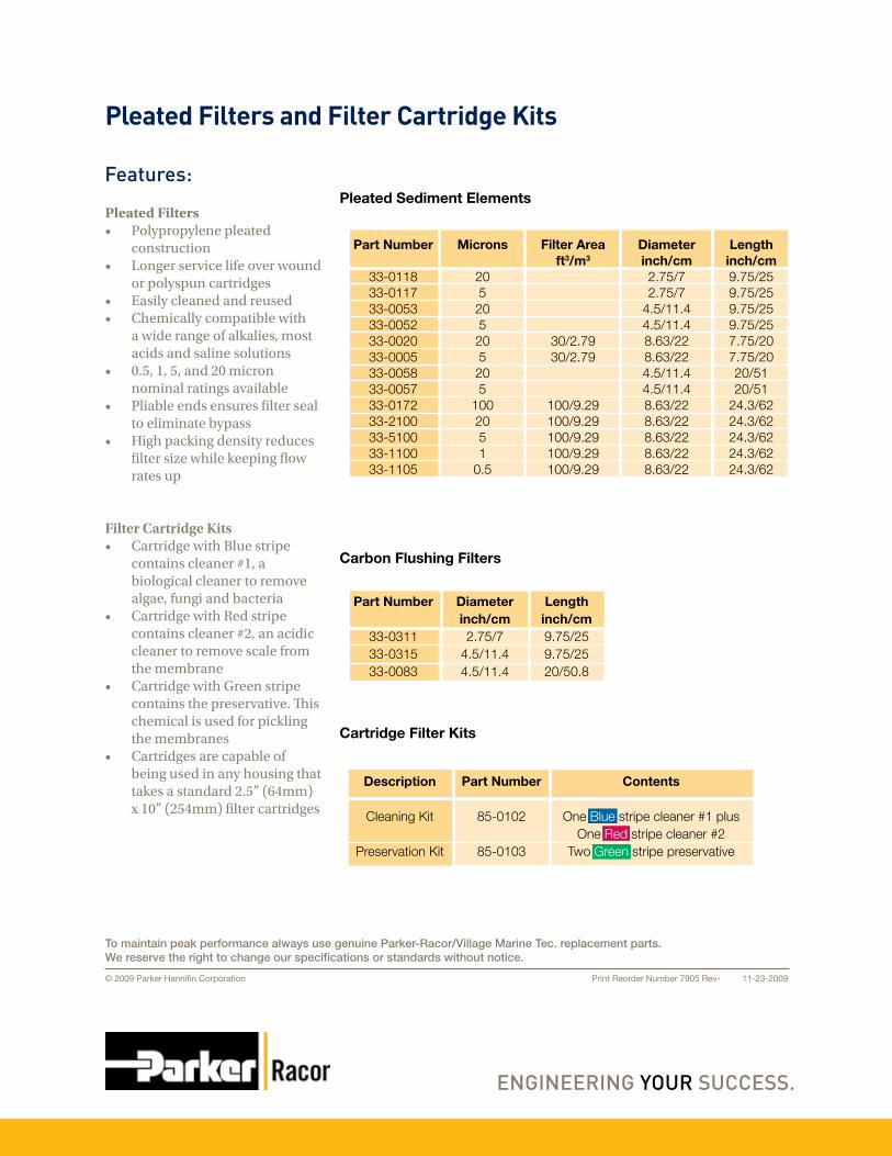
Pleated Filters• Polypropylene pleated
construction• Longer service life over wound
or polyspun cartridges• Easily cleaned and reused• Chemically compatible with
a wide range of alkalies, most acids and saline solutions
• 0.5, 1, 5, and 20 micron nominal ratings available
• Pliable ends ensures filter seal to eliminate bypass
• High packing density reduces filter size while keeping flow rates up
Filter Cartridge Kits• Cartridge with Blue stripe
contains cleaner #1, a biological cleaner to remove algae, fungi and bacteria
• Cartridge with Red stripe contains cleaner #2, an acidic cleaner to remove scale from the membrane
• Cartridge with Green stripe contains the preservative. This chemical is used for pickling the membranes
• Cartridges are capable of being used in any housing that takes a standard 2.5” (64mm) x 10” (254mm) filter cartridges
Pleated Filters and Filter Cartridge Kits
Features:
Carbon Flushing Filters
Cartridge Filter Kits
Pleated Sediment Elements
Part Number
33-011833-011733-005333-005233-002033-000533-005833-005733-017233-210033-510033-110033-1105
Microns
205
205
205
205
1002051
0.5
Filter Areaft3/m3
30/2.7930/2.79
100/9.29 100/9.29100/9.29100/9.29100/9.29
Diameterinch/cm2.75/72.75/7
4.5/11.44.5/11.48.63/228.63/224.5/11.44.5/11.48.63/22 8.63/228.63/228.63/228.63/22
Lengthinch/cm9.75/259.75/259.75/259.75/257.75/207.75/2020/5120/51
24.3/62 24.3/6224.3/6224.3/6224.3/62
Diameterinch/cm2.75/7
4.5/11.44.5/11.4
Lengthinch/cm9.75/259.75/2520/50.8
Part Number
33-031133-031533-0083
Part Number
85-0102
85-0103
Description
Cleaning Kit
Preservation Kit
Contents
One Blue stripe cleaner #1 plusOne Red stripe cleaner #2
Two Green stripe preservative
Print Reorder Number 7905 Rev- 11-23-2009© 2009 Parker Hannifin Corporation
To maintain peak performance always use genuine Parker-Racor/Village Marine Tec. replacement parts.We reserve the right to change our specifications or standards without notice.