puritan bennett 840 ventilator user’s pocket guidertasap.com/ppt/pb840quickguide.pdf · ii...
TRANSCRIPT

iPuritan Bennett™ 840 Ventilator Pocket Guide
Puritan Bennett™ 840 Ventilator User’s Pocket Guide

ii Puritan Bennett™ 840 Ventilator Pocket Guide
The Puritan Bennett™ 840 Ventilator System is manufactured in accordance with Covidien proprietary information, covered by one or more of the following U.S. Patents and foreign equivalents: 4,954,799; 5,161,525; 5,271,389; 5,301,921; 5,319,540; 5,339,807; 5,368,019; and 5,390,666. 840, Flow-by, DualView, SandBox, SmartAlert and Bi-Level are trademarks of Covidien Puritan Bennett™.
The information contained in this manual is the sole property of Covidien and may not be duplicated without permission. This manual may be revised or replaced by Covidien at any time and without notice. While the information set forth herein is believed to be accurate, it is not a substitute for the exercise of professional judgment.
The ventilator should be operated and serviced only by trained professionals. Covidien acknowledges sole responsibility with respect to the ventilator, and its use, as stated in the limited warranty provided.
Nothing in this publication shall limit or restrict in any way Covidien the right to revise or otherwise change or modify the equipment (including its software) described herein, without notice. In the absence of an express, written agreement to the contrary, Covidien has no obligation to furnish any such revisions, changes or modifications to the owner or user of the equipment (including its software) described herein.

iiiPuritan Bennett™ 840 Ventilator Pocket Guide
TaBle of conTenTsIntroduction . . . . . . . . . . . . . . . . . . . . . . . . . . . . . . . . . . . . . . . . . . . . . . . . . 1The Puritan Bennett™ 840 Ventilator . . . . . . . . . . . . . . . . . . . . . . . . . . . . 2Connections . . . . . . . . . . . . . . . . . . . . . . . . . . . . . . . . . . . . . . . . . . . . . . . . . 4
Power . . . . . . . . . . . . . . . . . . . . . . . . . . . . . . . . . . . . . . . . . . . . . . . . . . . . 4Air and oxygen supplies . . . . . . . . . . . . . . . . . . . . . . . . . . . . . . . . . . . . . . . 6Patient circuit . . . . . . . . . . . . . . . . . . . . . . . . . . . . . . . . . . . . . . . . . . . . . . . . 8Patient setup . . . . . . . . . . . . . . . . . . . . . . . . . . . . . . . . . . . . . . . . . . . . . . . .12
New patient setup . . . . . . . . . . . . . . . . . . . . . . . . . . . . . . . . . . . . . . . . .13Apnea settings . . . . . . . . . . . . . . . . . . . . . . . . . . . . . . . . . . . . . . . . . . . .14Calibrating the oxygen sensor . . . . . . . . . . . . . . . . . . . . . . . . . . . . . . .14Once patient setup is complete . . . . . . . . . . . . . . . . . . . . . . . . . . . . . .14Inspiratory pause . . . . . . . . . . . . . . . . . . . . . . . . . . . . . . . . . . . . . . . . . .15Expiratory pause . . . . . . . . . . . . . . . . . . . . . . . . . . . . . . . . . . . . . . . . . .15
Alarm settings . . . . . . . . . . . . . . . . . . . . . . . . . . . . . . . . . . . . . . . . . . . . . . .21Main setting changes . . . . . . . . . . . . . . . . . . . . . . . . . . . . . . . . . . . . . . . . .22Mode, breath type and batch (multiple) changes . . . . . . . . . . . . . . . . .23
Previous setup . . . . . . . . . . . . . . . . . . . . . . . . . . . . . . . . . . . . . . . . . . . .23Humidification type, humidifier volume, O2 sensor
enable/disable, and disconnect sensitivity (DSENS) . . . . . . . . . . .24Constant during rate change . . . . . . . . . . . . . . . . . . . . . . . . . . . . . . . .25
Alarm handling . . . . . . . . . . . . . . . . . . . . . . . . . . . . . . . . . . . . . . . . . . . . .26Alarm silence . . . . . . . . . . . . . . . . . . . . . . . . . . . . . . . . . . . . . . . . . . . . .27Alarm reset . . . . . . . . . . . . . . . . . . . . . . . . . . . . . . . . . . . . . . . . . . . . . . .27Alarm log . . . . . . . . . . . . . . . . . . . . . . . . . . . . . . . . . . . . . . . . . . . . . . . .28Alarm messages . . . . . . . . . . . . . . . . . . . . . . . . . . . . . . . . . . . . . . . . . . .29
Graphics. . . . . . . . . . . . . . . . . . . . . . . . . . . . . . . . . . . . . . . . . . . . . . . . . . . .37Display . . . . . . . . . . . . . . . . . . . . . . . . . . . . . . . . . . . . . . . . . . . . . . . . . .37Color . . . . . . . . . . . . . . . . . . . . . . . . . . . . . . . . . . . . . . . . . . . . . . . . . . . .37Freezing . . . . . . . . . . . . . . . . . . . . . . . . . . . . . . . . . . . . . . . . . . . . . . . . .39Plot setup . . . . . . . . . . . . . . . . . . . . . . . . . . . . . . . . . . . . . . . . . . . . . . . .39Once graphics are displayed . . . . . . . . . . . . . . . . . . . . . . . . . . . . . . . .40
The ? key . . . . . . . . . . . . . . . . . . . . . . . . . . . . . . . . . . . . . . . . . . . . . . . . . . .41Bi-Level . . . . . . . . . . . . . . . . . . . . . . . . . . . . . . . . . . . . . . . . . . . . . . . . . . . .42
Patient setup. . . . . . . . . . . . . . . . . . . . . . . . . . . . . . . . . . . . . . . . . . . . . .42Constant during rate change . . . . . . . . . . . . . . . . . . . . . . . . . . . . . . . .43Using pressure support with Bi-Level . . . . . . . . . . . . . . . . . . . . . . . .44Manual inspiration in Bi-Level mode . . . . . . . . . . . . . . . . . . . . . . . .45
Tube compensation . . . . . . . . . . . . . . . . . . . . . . . . . . . . . . . . . . . . . . . . . .46Patient setup. . . . . . . . . . . . . . . . . . . . . . . . . . . . . . . . . . . . . . . . . . . . . .46
Ventilator self-tests . . . . . . . . . . . . . . . . . . . . . . . . . . . . . . . . . . . . . . . . . .48Running SST . . . . . . . . . . . . . . . . . . . . . . . . . . . . . . . . . . . . . . . . . . . . .48
Safety modes . . . . . . . . . . . . . . . . . . . . . . . . . . . . . . . . . . . . . . . . . . . . . . . .53Preventive maintenance . . . . . . . . . . . . . . . . . . . . . . . . . . . . . . . . . . . . . .55

iv Puritan Bennett™ 840 Ventilator Pocket Guide
fiGUres
Figure 1. Puritan Bennett™ 840 Ventilator components . . . . . . . . . 3Figure 2. Connecting the ventilator power cord . . . . . . . . . . . . . . . . 4Figure 3. Connecting the air and oxygen supplies . . . . . . . . . . . . . . 6Figure 4. Connecting the patient circuit . . . . . . . . . . . . . . . . . . . . . . 8Figure 5. Installing the expiratory filter and
collector vial . . . . . . . . . . . . . . . . . . . . . . . . . . . . . . . . . . . . . . 9Figure 6. Using the collector vial with or without
drain bag . . . . . . . . . . . . . . . . . . . . . . . . . . . . . . . . . . . . . . . .10Figure 7. Ventilator startup screen . . . . . . . . . . . . . . . . . . . . . . . . . .12Figure 8. Puritan Bennett™ 840 Ventilator
graphic user interface (GUI) . . . . . . . . . . . . . . . . . . . . . . .20Figure 9. Alarm setup . . . . . . . . . . . . . . . . . . . . . . . . . . . . . . . . . . . . .21Figure 10. Constant during rate change
(inspiratory time selected) . . . . . . . . . . . . . . . . . . . . . . . . .25Figure 11. Alarm indicators . . . . . . . . . . . . . . . . . . . . . . . . . . . . . . . . .26Figure 12. Alarm log . . . . . . . . . . . . . . . . . . . . . . . . . . . . . . . . . . . . . . .29Figure 13. Alarm message format . . . . . . . . . . . . . . . . . . . . . . . . . . . .30Figure 14. Pressure-volume loop . . . . . . . . . . . . . . . . . . . . . . . . . . . . .38Figure 15. Bi-Level breath timing bar . . . . . . . . . . . . . . . . . . . . . . . . .43Figure 16. Bi-Level with pressure support . . . . . . . . . . . . . . . . . . . . .45
TaBles
Table 1. Inspiratory pause maneuver displays . . . . . . . . . . . . . . . .16Table 2. Alarm messages . . . . . . . . . . . . . . . . . . . . . . . . . . . . . . . . . .31Table 3. Ideal body weight (IBW) and tube I.D. . . . . . . . . . . . . . .47Table 4. Individual test results in SST . . . . . . . . . . . . . . . . . . . . . . .50Table 5. Overall SST results . . . . . . . . . . . . . . . . . . . . . . . . . . . . . . .51Table 6. Maintenance summary. . . . . . . . . . . . . . . . . . . . . . . . . . . .55

1Puritan Bennett™ 840 Ventilator Pocket Guide
inTrodUcTion
This pocket guide gives you a quick overview of how to set up and use the Puritan Bennett™ 840 Ventilator System.
As you read through this pocket guide, this symbol: ➪ asks you to take an action
This pocket guide is intended to supplement (not replace) the Puritan Bennett™ 840 Ventilator Operator’s and Technical Reference Manual, which should always be available while using the ventilator.
Different versions of the Puritan Bennett™ 840 Ventilator can have minor variations in labeling (e.g., keyboard over-lays and off-screen alarm status indicators).
For more detailed information on any of the topics covered in this pocket guide, please see the Puritan Bennett 840 Ventilator Operator’s and Technical Reference Manual. (Also please see the Puritan Bennett™ 840 Ventilator Service Manual.)
2 Puritan Bennett™ 840 Ventilator Pocket Guide
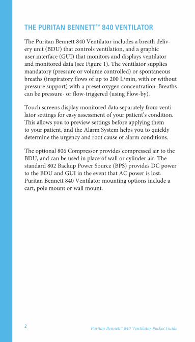
The PUriTan BenneTT™ 840 VenTilaTor
The Puritan Bennett 840 Ventilator includes a breath deliv-ery unit (BDU) that controls ventilation, and a graphic user interface (GUI) that monitors and displays ventilator and monitored data (see Figure 1). The ventilator supplies mandatory (pressure or volume controlled) or spontaneous breaths (inspiratory flows of up to 200 L/min, with or without pressure support) with a preset oxygen concentration. Breaths can be pressure- or flow-triggered (using Flow-by).
Touch screens display monitored data separately from venti-lator settings for easy assessment of your patient’s condition. This allows you to preview settings before applying them to your patient, and the Alarm System helps you to quickly determine the urgency and root cause of alarm conditions.
The optional 806 Compressor provides compressed air to the BDU, and can be used in place of wall or cylinder air. The standard 802 Backup Power Source (BPS) provides DC power to the BDU and GUI in the event that AC power is lost. Puritan Bennett 840 Ventilator mounting options include a cart, pole mount or wall mount.

3Puritan Bennett™ 840 Ventilator Pocket Guide
Graphic User Interface (GUI)
Compressor Cart
Breath Delivery Unit (BDU)
802 Backup Power Source (BPS)
fiGUre 1.Puritan Bennett 840 Ventilator components

4 Puritan Bennett™ 840 Ventilator Pocket Guide
connecTions
This section tells you how to connect the Puritan Bennett™ 840 Ventilator to AC power, air and oxygen supplies and the patient circuit.
Power
➪ Plug the ventilator power cord to AC power (see Figure 2). The power cord retainer protects against accidental disconnection, and must always be in place during operation.
To avoid electrical shock hazard, connect the ventilator power cord into a grounded AC power outlet.
Power cord retainer
Power cord
To AC power
WarninG
fiGUre 2. Connecting the ventilator power cord

5Puritan Bennett™ 840 Ventilator Pocket Guide
Normally, the Puritan Bennett™ 840 Ventilator System is mains-powered. The mandatory 802 Backup Power Source (BPS) operates the ventilator when AC power drops below a minimum level. The ventilator recharges the BPS during AC power operation.
noTe:The BPS is designed for short-term use only, and is not intended as a primary alternative power source. The BPS is intended to power the BDU and GUI only. In case of AC power loss, no power is available for the compressor or humidifier.
If you turn on the ventilator after it has been unplugged for an extended period, the LOW BATTERY alarm may become active. If so, recharge the BPS by leaving it connected to an operating ventilator for up to eight hours. If the LOW BATTERY alarm is still active or if the INOPERATIVE BATTERY alarm is active, the BPS battery must be replaced by a qualified service technician.

6 Puritan Bennett™ 840 Ventilator Pocket Guide
air and oxyGen sUPPlies
➪ Connect air and oxygen supplies to the ventilator (see Figure 3). The ventilator can use air and oxygen from cylinder or wall supplies. Supply pressures must be 35 to 100 psi (241 to 690 kPa).
Connect only air to the air inlet, and only oxygen to the oxygen inlet. Do not attempt to switch air and oxygen or connect any other gas.
Air inlet connector
Oxygen inlet conncer
Air hose (from air supply) Oxygen hose
(from oxygen supply)
Air inlet filter bowl
WarninG
fiGUre 3. Connecting the air and oxygen supplies

7Puritan Bennett™ 840 Ventilator Pocket Guide
To ensure that a constant gas supply is available to the patient, always connect at least two gas sources to the ventilator. (There are three gas source connections: the compressor, air inlet and oxygen inlet.)
To prevent damage to the ventilator, ensure that the connections to the air and oxygen supplies are clean and unlubricated, and that there is no water in the air or oxygen supply gas. If you suspect water in the air supply gas, use an external wall air water trap to prevent water damage to the ventilator and its components.
caUTion
WarninG

8 Puritan Bennett™ 840 Ventilator Pocket Guide
PaTienT circUiT
➪ Connect the patient circuit to the ventilator (see Figure 4).
Humidifier
(From patient)
(To patient)
Inspiratory filter
Tubing
Expiratory filter
Inspiratory limb of patient circuit
Collector vial
fiGUre 4. Connecting the patient circuit

9Puritan Bennett™ 840 Ventilator Pocket Guide
➪ Figure 5 shows you how to install the expiratory filter and collector vial to the ventilator. Attach the expiratory limb of the patient circuit to the filter’s expiratory limb connection.
Slide filter rim onto these tracks
Filter housing
area
Expiratory limb connection
Pull latch up to install filter, pull down to hold filter and collector vial in place
fiGUre 5. Installing the expiratory filter and collector vial

10 Puritan Bennett™ 840 Ventilator Pocket Guide
➪ Cap the collector vial drain port if you are not using the drain bag (see Figure 6).
➪ If you are using the drain bag, install clamp on tubing. Uncap collector vial drain port and install tubing to collector vial drain port. Connect other end of tubing to drain bag. If the ventilator is mounted on the cart, place the drain bag in the cart drawer (see Figure 6). The drain bag is designed to lie flat, and is not designed to be suspended.
Place drain bag in cart drawer
Tubing
fiGUre 6. Using the collector vial with or without drain bag
11Puritan Bennett™ 840 Ventilator Pocket Guide
Covidien recommends that you use one of the identified patient circuits (see the Puritan Bennett™ 840 Ventilator Operator’s and Technical Reference Manual for patient circuit testing specifications). Using a circuit with a higher resistance does not prevent ventilation, but can cause an SST fault or compromise the patient’s ability to breathe through the circuit.
noTe:To ensure optimum compliance compensation, Covidien recommends that you use low-compliance patient circuits. (For pediatric patients, the compliance compensation volume limit is four times the set tidal volume, in addition to the set tidal volume.)
noTe:To ensure optimum ventilation, use pediatric circuits for patients whose ideal body weight (IBW) is 24 kg (53 lbs) or less, and adult circuits for patients whose IBW is more than 24 kg.
WarninG

12 Puritan Bennett™ 840 Ventilator Pocket Guide
PaTienT seTUP
Once you turn on the ventilator or run SST, the ventilator runs POST, then displays the Ventilator Startup screen (see Figure 7) on the lower screen.
noTe:If TC was used on the previous patient setup, a note emphasizing tube type and tube I.D. appears below the SAME PATIENT button explanation.
➪ Touch SAME PATIENT, then press ACCEPT to continue ventilating with the most recent settings. Ventilation does not begin until a patient is connected.
➪ Touch NEW PATIENT to begin ventilating with new settings.
fiGUre 7. Ventilator startup screen

13Puritan Bennett™ 840 Ventilator Pocket Guide
noTe:If you are unsure of the meaning of any symbol for ventilator settings, alarms or monitored data, touch the symbol on the screen; its definition will appear at the left bottom corner of the lower screen. (Figure 8 shows where symbol definitions appear on the GUI.)
new patient setup
➪ Touch the IBW button, then turn the knob to adjust the IBW. (Many initial settings and setting limits are automatically determined based on the IBW.) The proposed value is shown in red.
➪ Touch CONTINUE (this button does not appear until you touch IBW), or touch RESTART to return to the Ventilator Startup screen.
➪ At the New Patient Setup screen, settings for mode, mandatory type (for manual inspirations, if the selected mode is SPONT), spontaneous type (if applicable) and trigger type appear. For any setting you want to change, touch its button, then turn the knob to select the value. When you are finished changing settings, touch CONTINUE.
➪ At the New Patient Settings screen, more settings appear. Touch each setting you want to change, then turn the knob to select its value. (To cancel a highlighted change, press CLEAR.)
➪ Press ACCEPT to put all settings into effect. Normal ventilation begins once a patient is connected. (Any time before you press ACCEPT, you can touch RESTART to restart setting changes.)

14 Puritan Bennett™ 840 Ventilator Pocket Guide
apnea settings
Although you aren’t required to change or confirm apnea settings, you should verify that they are appropriate for the patient. Apnea settings are automatically determined based on IBW, but can be changed.
➪ If you selected NEW PATIENT, the Current Apnea Settings screen appears at the end of patient setup.
➪ If you selected SAME PATIENT, touch the APNEA button at the bottom of the lower screen to view apnea settings.
➪ If you change any apnea settings, press ACCEPT to put new settings into effect.
calibrating the oxygen sensor
Press the 100% O2 /CAL 2 MIN key. This causes the ventilator to deliver 100% oxygen (if available) for two minutes and calibrates the oxygen sensor.
The ventilator’s oxygen monitoring feature is always active unless you disable the oxygen sensor (see the More Settings screen). The oxygen sensor is always enabled when you power up the ventilator.
once patient setup is complete
Once the settings are accepted, you can attach a patient to the ventilator. Ventilation only begins when the ventilator senses that a patient is attached. (If you attach a patient before completing setup, the ventilator begins safety ventilation and declares a PROCEDURE ERROR alarm that resets once patient setup is complete.)

15Puritan Bennett™ 840 Ventilator Pocket Guide
inspiratory pause
Pressing the INSP PAUSE key causes the ventilator to schedule an automatic pause maneuver as follows (see Table 1).
• At the next scheduled inspiration, the inspiratory and expiratory valves close to allow pressure to equilibrate between the patient and the circuit.
• The inspiratory pause continues until a stable pressure is reached or until two seconds elapse, whichever comes first.
• The graphics screen will automatically be displayed (if it is not already active). The trace freezes and the values for compliance and resistance are displayed.
• You can extend the pause beyond two seconds to a maximum of seven seconds by holding down the INSP PAUSE key.
expiratory pause
Pressing the EXP PAUSE key causes the ventilator to schedule an automatic expiratory pause maneuver as follows:
• Press EXP PAUSE key to schedule automatic expiratory pause maneuver.
• During the next exhalation, the inspiratory and expiratory valves close to allow pressure to equilibrate between the circuit and the patient.
• The expiratory pause continues until a stable pressure is reached or two seconds elapse, whichever comes first.
• The graphics screen will automatically be displayed (if it is not already active). The trace freezes and the values for intrinsic (auto) PEEP and total PEEP are displayed.
• You can extend the pause beyond two seconds to a maximum of 20 seconds by holding down the EXP PAUSE key.

16 Puritan Bennett™ 840 Ventilator Pocket Guide
TaBle 1. Inspiratory pause maneuver displays
C <
0.1
mL/
cm H
2O o
r pat
ient
flow
< 0
.1 L
/m
in. T
his p
oint
s to
ques
tiona
ble
inpu
ts to
th
e C
equ
atio
n, w
hich
wou
ld in
turn
rend
er
R qu
estio
nabl
e. T
he lo
w p
atie
nt fl
ow is
bel
ow
the
thre
shol
d of
relia
ble
mea
sure
men
t.
The
diffe
renc
e in
pre
ssur
e be
twee
n en
d pl
a-te
au a
nd e
nd e
xhal
atio
n <
0.1
cm H
2O. T
his
is be
low
the
limits
of r
elia
ble
reso
lutio
n. T
he
R an
d C
val
ues a
re th
eref
ore
ques
tiona
ble.
C ≤
0 m
L/cm
H2O
or C
< 5
00 m
L/cm
H2O
. Th
ese
mea
sure
men
ts a
re o
utsid
e of
ph
ysio
logi
cal l
imits
.
C (*
****
*)
C (*
****
*)
C (
0 )
or
C (5
00)
R (*
****
*)
R (*
****
*)
R (
)
Mes
sage
as
dict
ated
by
othe
r te
sts
Che
ck th
e br
eath
ing
wav
efor
ms a
nd
mon
itore
d pa
tient
dat
a fo
r clu
es
abou
t the
se q
uest
iona
ble
inpu
ts.
Che
ck th
e br
eath
ing
wav
efor
ms a
nd
mon
itore
d pa
tient
dat
a fo
r clu
es
abou
t the
se q
uest
iona
ble
inpu
ts.
Che
ck th
e pa
tient
-ven
tilat
or in
tera
c-tio
n, th
e br
eath
ing
wav
efor
ms,
and
the
patie
nt c
ircui
t for
und
erly
ing
caus
es.
Whe
n yo
u se
e co
mpl
ianc
e (c
):o
r re
sist
ance
(r)
(if d
ispl
ayed
):it
mea
ns:
do
this
:

17Puritan Bennett™ 840 Ventilator Pocket Guide
R ≤
0 cm
H2O
/L/s
or R
< 5
00 c
m H
2O/L
/s.
Thes
e m
easu
rem
ents
are
out
side
of p
hysi-
olog
ical
lim
its.
Sub-
thre
shol
d in
put v
alue
(s) C
< 1
/3 o
f ven
-til
ator
bre
athi
ng sy
stem
com
plia
nce
(der
ived
fr
om S
ST).
Both
C a
nd R
are
que
stio
nabl
e.
Exha
latio
n w
as n
ot c
ompl
ete.
Thi
s ren
ders
en
d-ex
pira
tory
pre
ssur
e an
d to
tal e
xhal
ed
flow
val
ues q
uest
iona
ble.
C (
)
Mes
sage
as
dict
ated
by
othe
r tes
ts
C (x
xx)
C (x
xx)
Inco
mpl
ete
exha
latio
n
R ( 0
) or
R
(500
)
R (y
yy)
R (y
yy)
Inco
mpl
ete
exha
latio
n
Che
ck th
e pa
tient
-ven
tilat
or
inte
ract
ion,
the
brea
thin
g
wav
efor
ms,
and
the
patie
nt
circ
uit f
or u
nder
lyin
g ca
uses
.
If th
e pa
tient
’s IB
W ≤
24
kg, c
onsid
er
inst
allin
g a
pedi
atric
pat
ient
circ
uit.
Che
ck fo
r an
insu
ffici
ent e
xpira
tory
in
terv
al. I
f pos
sible
, sho
rten
in
spira
tion
time
and
redu
ce
resp
irato
ry ra
te.
Whe
n yo
u se
e co
mpl
ianc
e (c
):o
r re
sist
ance
(r)
(if d
ispl
ayed
):it
mea
ns:
do
this
:
TaBle 1. Inspiratory pause maneuver displays (continued)

18 Puritan Bennett™ 840 Ventilator Pocket Guide
Plat
eau
is no
t “fla
t” (l
ung
and
circ
uit
pres
sure
s did
not
equ
ilibr
ate)
or p
ause
pr
essu
re w
as e
xces
sivel
y no
isy. T
hese
pr
oble
ms r
ende
r R a
nd C
que
stio
nabl
e.
C <
1.0
mL/
cm H
2O. T
his r
esul
ts fr
om
ques
tiona
ble
inpu
t dat
a. T
his o
ut-o
f-ra
nge
valu
e al
so re
nder
s R q
uest
iona
ble.
R >
150
cm H
2O/L
/s. T
his r
esul
ts fr
om
ques
tiona
ble
inpu
t dat
a, p
ossib
ly C
.
R (y
yy)
No
plat
eau
R (y
yy)
Que
stio
nabl
e m
easu
rem
ent
R (y
yy)
Out
of r
ange
If pl
atea
u co
ntin
ues t
o de
clin
e, c
heck
fo
r a le
ak in
the
brea
thin
g ci
rcui
t, po
ssib
ly a
roun
d th
e cu
ff. If
pla
teau
is
unst
able
, che
ck fo
r moi
stur
e co
nden
sing
in a
“laz
y” lo
op o
r a
brea
thin
g ci
rcui
t bei
ng ji
ggle
d.
Che
ck th
e br
eath
ing
wav
efor
ms a
nd
mon
itore
d pa
tient
dat
a fo
r clu
es
abou
t the
se q
uest
iona
ble
inpu
ts.
Che
ck th
e br
eath
ing
wav
efor
ms a
nd
mon
itore
d pa
tient
dat
a fo
r clu
es
abou
t the
se q
uest
iona
ble
inpu
ts.
or
resi
stan
ce (r
) (if
dis
play
ed):
it m
eans
:d
o th
is:
TaBle 1. Inspiratory pause maneuver displays (continued)
Whe
n yo
u se
e co
mpl
ianc
e (c
):

19Puritan Bennett™ 840 Ventilator Pocket Guide
or
resi
stan
ce (r
) (if
dis
play
ed):
it m
eans
:d
o th
is:
The
pres
sure
rose
slow
ly a
t the
end
of t
he
squa
re fl
ow w
avef
orm
. Thi
s sug
gest
s tha
t th
e pr
essu
res,
volu
mes
and
flow
s inv
olve
d ar
e m
inim
al a
nd q
uest
iona
ble.
Thi
s is n
ot
expe
cted
dur
ing
norm
al v
entil
atio
n.
The
diffe
renc
e be
twee
n th
e ci
rcui
t pre
ssur
e at
the
end
of th
e pl
atea
u an
d th
e pr
essu
re
at th
e en
d of
exh
alat
ion
< 0.
5 cm
H2O
. Thi
s re
sults
in a
que
stio
nabl
e R
valu
e.
R (y
yy)
Que
stio
nabl
e m
easu
rem
ent
R (y
yy)
Que
stio
nabl
e m
easu
rem
ent
Che
ck th
e pr
essu
re-t
ime
wav
efor
m
to se
e w
heth
er th
e pa
tient
del
ayed
in
spira
tion
until
the
end
of g
as
deliv
ery.
C
heck
for a
hig
hly
com
plia
nt lu
ng
infla
ted
sligh
tly. I
f the
tida
l vol
ume
can
be sa
fely
incr
ease
d, tr
y th
at.
TaBle 1. Inspiratory pause maneuver displays (continued)W
hen
you
see
com
plia
nce
(c):

20 Puritan Bennett™ 840 Ventilator Pocket Guide
The top of the upper screen shows monitored data (data outside the normal range flashes). Once normal ventilation is in progress, ventilator settings are displayed across the top of the lower screen. (Figure 8 shows how information is displayed on the GUI.)
Upper screen:monitored information (alarms, patient data)
Lower screen: ventilator settings
Off-screen keys Knob
fiGUre 8. Puritan Bennett™ 840 Ventilator graphic user interface (GUI)
21Puritan Bennett™ 840 Ventilator Pocket Guide
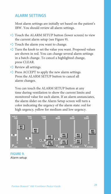
alarm seTTinGs
Most alarm settings are initially set based on the patient’s IBW. You should review all alarm settings.
➪ Touch the ALARM SETUP button (lower screen) to view the current alarm setup (see Figure 9).
➪ Touch the alarm you want to change.➪ Turn the knob to set the value you want. Proposed values
are shown in red. You can change several alarm settings in a batch change. To cancel a highlighted change, press CLEAR.
➪ Review all settings.➪ Press ACCEPT to apply the new alarm settings.
Press the ALARM SETUP button to cancel all alarm changes.
You can touch the ALARM SETUP button at any time during ventilation to show the current limits and monitored value for each alarm. If an alarm annunciates, the alarm slider on the Alarm Setup screen will turn a color indicating the urgency of the alarm state: red for high urgency, yellow for medium and low urgency.
fiGUre 9. Alarm setup

22 Puritan Bennett™ 840 Ventilator Pocket Guide
main seTTinG chanGes
Main settings are the buttons displayed at the top of the lower screen, and you can only change them individually. Follow these steps to change main settings:
➪ Touch the setting you want to change➪ Turn the knob to the set value➪ Press ACCEPT to apply the new setting
Remember: touch, turn, ACCEPT!
noTe:The upper limits for the spontaneous exhaled tidal volume and mandatory exhaled tidal volume alarms are always the same. Changing the upper limit of one alarm automatically changes the upper limit of the other.

23Puritan Bennett™ 840 Ventilator Pocket Guide
mode, BreaTh TyPe and BaTch
(mUlTiPle) chanGes
➪ Touch the SETUP button on the lower screen. The Current Vent Setup screen appears.
➪ To change ventilation setup (mode, mandatory breath type, spontaneous type or trigger type), touch its button, then turn the knob to set the value. Proposed changes are shown in red. (Press CLEAR to cancel a change you’ve just made.)
➪ Once you’ve made all the changes you want (you don’t have to make any changes at all), touch CONTINUE. Appropriate settings for the ventilation setup you’ve selected appear on the lower screen.
➪ For each of the current ventilator settings you want to change, touch its button, then turn the knob to set its value. (Press CLEAR to cancel a change you’ve just made.)
➪ Once you’ve made any changes you want, review the settings, then press ACCEPT to apply all the new settings at the same time. (Touch SETUP to cancel all changes.)
Previous setup
Once ventilator settings are in effect, the PREVIOUS SETUP button appears at the bottom of the lower screen when you press SETUP, and allows you to restore the entire previous setup (including alarm and apnea settings) that was in effect immediately before you made setting changes using the Ventilator Setup screen.
➪ To restore the previous setup, touch PREVIOUS SETUP, then press ACCEPT.

24 Puritan Bennett™ 840 Ventilator Pocket Guide
humidification type, humidifier volume, o2 sensor enable/disable and disconnect sensitivity (dsens)
To view or change:
➪ Touch the OTHER SCREENS button, then touch the MORE SETTINGS button.
➪ Touch each setting you want to change (you can change multiple settings), then turn the knob to set its value. To leave settings unchanged, touch the OTHER SCREENS button again.
➪ Press ACCEPT to apply the new settings.

25Puritan Bennett™ 840 Ventilator Pocket Guide
constant during rate change
If you selected pressure control (PC), you can select one of three timing variables (inspiratory time, I:E ratio, or expiratory time) to be held constant when the respiratory rate setting changes.
➪ Touch SETUP.➪ Touch CONTINUE. The breath timing bar appears in the
lower screen (see Figure 10).➪ Touch one of the lock icons to select TI, I:E, or TE as
the setting that remains constant when the rate setting changes.
➪ Review settings and change if necessary, then press ACCEPT. The value displayed is the one held constant during rate changes, and becomes the only setting you can adjust directly.
noTe:You can change the value of the constant setting at any time, but the value does not change as a result of changing the rate setting.
fiGUre 10. Constant during rate change (inspiratory time selected)

26 Puritan Bennett™ 840 Ventilator Pocket Guide
alarm handlinG
The SmartAlert Alarm System offers prioritized alarm annunciation that distinguishes primary alarms from secondary, dependent alarms (that is, alarms that arise due to the initial alarm condition) and indicates the urgency level of each alarm. An alarm log keeps a time-and-date-stamped record of alarms, alarm silences, and resets in order of occurrence.
Alarms on the Puritan Bennett™ 840 Ventilator are classified as high-, medium- or low-urgency (see Figure 11).
noTe:You can always change an alarm setting even when alarms are active. You do not need to press ALARM RESET or wait for the alarm to autoreset.
Low-urgency alarm indicator (yellow): Indicates a change in the patient-ventilator system.
High-urgency alarm indicator (red): Immediate attention required to ensure patient safety.
Medium-urgency alarm indicator (yellow): Prompt attention required.
fiGUre 11. Alarm indicators

27Puritan Bennett™ 840 Ventilator Pocket Guide
alarm silence
Pressing ALARM SILENCE mutes the alarm sound for two minutes. The key’s LED lights during the silence period, and turns off if the alarm is reset. Every time you press ALARM SILENCE, the two-minute silence period restarts. An on-screen alarm silence notification appears on the display when alarm silence is active.
Never leave patient unattended when ALARM SILENCE is activated. ALARM RESET will cancel silence.
alarm reset
Pressing the off-screen ALARM RESET key resets the detection algorithms of all active alarms, except for these:
AC POWER LOSSCOMPRESSOR INOPERATIVEDEVICE ALERTO2 SENSORINOPERATIVE BATTERYLOW AC POWER LOW BATTERYNO AIR SUPPLYNO O2 SUPPLYPROCEDURE ERROR
Pressing ALARM RESET has no effect on patient data. If an alarm condition persists, the alarm becomes active again, according to the detection algorithm for that alarm. For example, if the APNEA alarm is active, ALARM RESET resets the apnea detection algorithm to its initial state and returns the ventilator to normal ventilation.
WarninG

28 Puritan Bennett™ 840 Ventilator Pocket Guide
Pressing ALARM RESET cancels alarm silence if active (this avoids silencing an alarm condition that arises shortly after pressing ALARM RESET). Pressing ALARM RESET clears any high-urgency alarm that has autoreset (and the steadily lit high-urgency alarm indicator turns off).
ALARM RESET gives you a way to return the ventilator to normal operation if an alarm condition has been resolved, without waiting for alarm detection algorithms to reset the alarm.
alarm log
To view the alarm log, touch the ALARM LOG button on the upper screen. The alarm log shows alarm events (including time-and-date-stamped alarms, silences and resets) in order of occurrence, with the most recent event at the top of the list (see Figure 12). The alarm log can store up to 80 of the most recent entries. Completing a new patient setup clears the alarm log.
A question mark in a triangle appears on the ALARM LOG button if the log includes an event that hasn’t been viewed yet. The question mark in a triangle disappears after you’ve viewed the event.
To scroll through the alarm log, move the scroll box up or down and turn the knob to page through the alarm log. An icon shows your relative position in the log.

29Puritan Bennett™ 840 Ventilator Pocket Guide
alarm messages
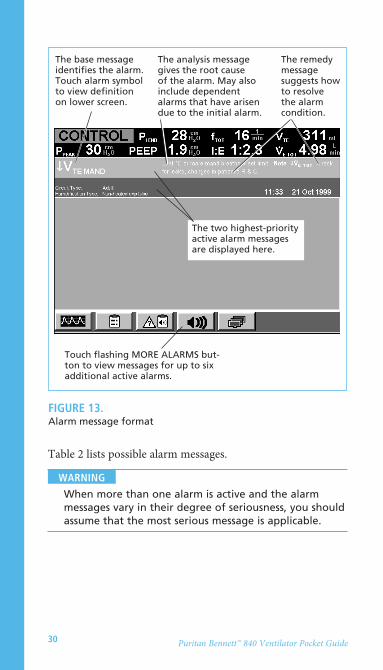
The upper screen displays the two highest-urgency active alarms. Alarms are color coded, both on the Alarm Setup screen and in the alarm status section on the upper screen. Red for high urgency; yellow for medium and low urgency. An alarm icon flashes on the MORE ALARMS button if there are other active alarms. Pressing the icon displays a full screen of up to eight active alarms.
Each alarm message consists of a base message, an analysis message (supplementary information that includes any associated alarm conditions) and a remedy message that suggests corrective actions (see Figure 13).
Alarm log button Indicates that log includes unread entries
Touch symbols to see definition at bottom of screen
Touch scroll box and turn rotary encoder to scroll through log
fiGUre 12. Alarm log
30 Puritan Bennett™ 840 Ventilator Pocket Guide
Table 2 lists possible alarm messages.
When more than one alarm is active and the alarm messages vary in their degree of seriousness, you should assume that the most serious message is applicable.
WarninG
The base message identifies the alarm. Touch alarm symbol to view definition on lower screen.
The analysis message gives the root cause of the alarm. May also include dependent alarms that have arisen due to the initial alarm.
The two highest-priority active alarm messages are displayed here.
Touch flashing MORE ALARMS but-ton to view messages for up to six additional active alarms.
The remedy message suggests how to resolve the alarm condition.
fiGUre 13. Alarm message format

31Puritan Bennett™ 840 Ventilator Pocket Guide
The power switch is ON, AC power is not available, and the ventilator is being powered by the backup power source (BPS).
The set apnea interval has elapsed without the ventilator, patient or operator triggering a breath.
There is a disconnection in the patient circuit before the patient wye or patient disconnect is detected following power restoration from an unintentional power loss with the power switch ON.
Compressor cannot maintain sufficient supply pressure.
A background test or power on self-test (POST) has detected a problem.
Prepare for power loss. Obtain alternate ventilation. Check integrity of AC power source. Contact service if necessary.
Check patient and settings.
Check patient. Reconnect patient circuit. Press ALARM RESET.
Check patient. Obtain alternate ventilation. Remove ventilator from use and contact service.
Check patient. If prompted to do so, obtain alternate ventilation or contact service.
TaBle 2. Alarm messages
AC POWER LOSS
APNEA
CIRCUIT DISCONNECT
COMPRESSOR INOPERATIVE
DEVICE ALERT
When you see It means: Do this: this message:

32 Puritan Bennett™ 840 Ventilator Pocket Guide
Background checks have detected a problem with the O2 sensor.
The measured airway pressure is equal to or greater than the set limit. Reduced tidal volume likely.
The O2% measured during any phase of a breath cycle is 7% (12% during the first hour of operation) or more above the O2% setting for at least 30 seconds. (These percentages increase by 5% for four minutes following a decrease in the O2% setting.)
The patient’s exhaled tidal volume for any breath is equal to or greater than the set limit.
The patient’s expiratory minute volume is equal to or greater than the set limit.
O2 sensor is out of calibration or has failed. Press 100% O2 CAL; replace or disable the sensor.
Check patient, patient circuit and endotracheal tube.
Check patient, air and oxygen supplies, oxygen analyzer and ventilator.
Check patient and settings. Consider whether the patient’s compliance or resistance has changed.
Check patient and settings.
O2 SENSOR
PCIRC (High circuit pressure)
O2% (High delivered O2%)
VTE (High exhaled tidal volume)
V.
E TOT (High exhaled total minute volume)
When you see it means: do this: this message:
TaBle 2. Alarm messages (continued)

33Puritan Bennett™ 840 Ventilator Pocket Guide
V.
ti SPONT Alarm
fTOT (High respira-tory rate)
PVENT (High internal ventilator pressure)
PCOMP
INOPERATIVE BATTERY
INSPIRATION TOO LONG
Check patient. Check for leaks, tube type/I.D. setting.
Check patient and settings.
Check patient. Obtain alternate ventilation. Remove ventilator from use and contact service.
Check patient. Check for leaks, tube type/I.D. setting.
Contact service.
Check patient. Check for leaks.
The delivered volume of any tube compensated (TC) breath is equal to or greater than the inspired tidal volume limit. Ventilator transitions to exhalation.
The breath rate from all breaths is greater than or equal to the set limit.
The inspiratory pressure transducer has measured a pressure of at least 100 cm H2O. Active only during volume-controlled breaths. Ventilator transitions to exhalation. Reduced tidal volume likely.
The target pressure of a tube compensated (TC) breath equals the PCIRC limit. This limit is equal to the setting of PPEAk. Inspiration pressure is limited during this alarm.
BPS is installed but not functioning.
IBW-based inspiratory time for a spontaneous breath exceeds ventilator-set limit.
When you see it means: do this: this message:
TaBle 2. Alarm messages (continued)

34 Puritan Bennett™ 840 Ventilator Pocket Guide
The ventilator power switch is on and there is insufficient power from the AC supply and the BPS. There may not be a visual indicator for this alarm, but an independent audio alarm sounds for at least 120 seconds.
Mains AC power has dropped below 80% of nominal voltage for at least one second. Warns that AC power has dropped significantly, and that a more severe power drop may be imminent. The ventilator turns off the compressor (if installed), and otherwise operates normally.
The BPS has less than approximately two minutes of operational time remaining.
Check integrity of AC power and BPS connections. Obtain alternate ventilation.
Check integrity of connection to AC power. Check AC power supply.
Replace BPS or allow it to recharge during normal ventilator operation.
LOSS OF POWER
LOW AC POWER
LOW BATTERY
When you see it means: do this: this message:
TaBle 2. Alarm messages (continued)

35Puritan Bennett™ 840 Ventilator Pocket Guide
↓O2% (Low delivered O2%)
↓VTE MAND (Low exhaled mandatory tidal volume)
↓VTE SPONT (Low exhaled spontaneous tidal volume)
↓V.
E TOT (Low exhaled total minute volume)
NO AIR SUPPLY
Check patient, air and oxygen supplies, oxygen analyzer and ventilator. Calibrate oxygen sensor (press 100% O2/CAL 2 min key).
Check patient. Check for leaks or changes in the patient’s resistance or compliance.
Check patient and settings.
Check patient and settings.
Check patient and air source. Obtain alternate ventilation.
The O2% measured during any phase of a breath cycle is 7% (12% during the first hour of operation) or more below the O2% setting for at least 30 seconds, or below 18%. (These percentages increase by 5% for four minutes following an increase in the O2% setting.)
The patient’s exhaled mandatory tidal volume is less than or equal to the set limit.
The patient’s exhaled spontaneous tidal volume is less than or equal to the set limit.
The minute volume for all breaths is less than or equal to the set limit.
Air supply pressure is less than the minimum required pressure for correct ventilator operation throughout its range of flows. Accurate O2% delivery may be compromised. You cannot set or disable the NO AIR SUPPLY alarm.
When you see it means: do this: this message:
TaBle 2. Alarm messages (continued)

36 Puritan Bennett™ 840 Ventilator Pocket Guide
Oxygen supply pressure is less than the minimum required pressure for correct ventilator operation throughout its range of flows. Accurate O2% delivery may be compromised. You cannot set or disable the NO O2 SUPPLY alarm.
Patient attached before ventilator startup is complete. Safety ventilation is active.
Patient circuit is severely occluded.
Check patient and oxygen source. Obtain alternate ventilation.
Provide alternate ventilation. Complete ventilator startup procedure.
Check patient. Obtain alternate ventilation if necessary. Check patient circuit for crimps, blocked filter. If problem persists, remove ventilator from use and contact service.
NO O2 supply
PROCEDURE ERROR
SEVERE OCCLUSION
When you see it means: do this: this message:
TaBle 2. Alarm messages (continued)

37Puritan Bennett™ 840 Ventilator Pocket Guide
GraPhics
The graphics function displays real-time patient data, including:
• Pressure-time curve• Flow-time curve• Volume-time curve• Pressure-volume loop
display
➪ To display the most recently selected graphics, press the GRAPHICS button at the bottom of the upper screen.
• If the pressure-volume loop is selected, the loop for the next full breath is displayed, then updated every other breath. The inspiratory area is calculated based on the area inside the loop to the left of the baseline (see Figure 14).
• Curves (pressure-time, flow-time and volume-time) are drawn on the screen at the start of a breath, beginning with the last 0.5 second of the previous breath.
color
Curves and loops are enhanced by color:
• Inspiration is green
• Expiration is yellow
• Spontaneous breaths are orange

38 Puritan Bennett™ 840 Ventilator Pocket Guide
Graphics are automatically displayed when you press the EXP PAUSE or INSP PAUSE key. The measured values for intrinsic and total PEEP are displayed at the end of the expiratory pause. The measured values for compliance and resistance (for VC with a square flow pattern) are displayed at the end of an inspiratory pause. During both the expiratory pause and inspiratory pause, the most recently selected graphics are displayed and frozen.
Graphics won’t be displayed when:
• The ventilator begins apnea ventilation or safety ventilation. (However, you can choose to redisplay graphics by pressing the graphics button.)
• You touch the MORE PATIENT DATA, ALARM LOG, MORE ALARMS or OTHER SCREENS button.
Inspiratory area
fiGUre 14. Pressure-volume loop

39Puritan Bennett™ 840 Ventilator Pocket Guide
freezing
Follow these steps to freeze graphics on the screen:
➪ Touch FREEZE. The screen flashes the message “FREEZING,” the UNFREEZE button appears, and the scaling buttons disappear. Plotting continues until the screen is full.
➪ Once the screen is filled and frozen, the other onscreen scaling buttons reappear. You can now redo the plot setup and adjust the scales for the last 48 seconds of frozen data. (The pressure-volume display shows the most recent full breath within the 48-second freeze period.)
➪ Press UNFREEZE at any time to resume real-time graphics display.
Graphics remain frozen even if you switch to another screen (for example, MORE ALARMS).
Plot setup
You can choose to display one or two time curves at a time. (The pressure-volume loop uses the entire screen, so no other waveform can be displayed at the same time.)
➪ Touch the graphics button at the lower left of the upper screen. Graphics appear.
➪ Touch PLOT SETUP at the upper left of the screen. Touch Plot 1, then turn the knob to select any one of the waveforms. (If you select pressure-volume, which uses the entire screen, Plot 2 disappears.)
➪ Touch Plot 2, if applicable. Turn the knob to select either of the two remaining waveforms or none. If you select none, only one enlarged plot (with higher resolution) appears.
➪ Touch CONTINUE to display the graphics you’ve selected. (You don’t have to press ACCEPT.)

40 Puritan Bennett™ 840 Ventilator Pocket Guide
once graphics are displayed
Setting baseline pressure:
➪ To move the baseline on a pressure-volume loop, touch the baseline pressure button, then use the knob to position the baseline.
The default position of the baseline is the PEEP setting. If the PEEP setting changes, the baseline resets to PEEP.
Adjusting scales:
➪ To adjust vertical and horizontal scales, touch the arrow buttons, then turn the knob to select.
41Puritan Bennett™ 840 Ventilator Pocket Guide
The ? key
The ? key on the GUI displays basic operating information about the Puritan Bennett™ 840 Ventilator, including:
• A few basics — information about screens, sounds, keys and symbols.
• Ventilator, alarm and apnea settings.
• New patient setup — how to configure the ventilator for a new patient.
• How to view patient data, including graphics.
• Graphics — setting up, viewing and freezing waveforms and loops.
• Alarm handling — what to do in case of alarm.
• Short self-test (SST).
• Service, including O2 sensor calibration, cleaning, periodic maintenance and when to call for help.

42 Puritan Bennett™ 840 Ventilator Pocket Guide
Bi-leVel
Bi-Level is a breath mode in which the patient has the ability to breathe spontaneously at two levels of PEEP. Its pressure waveform resembles pressure controlled ventilation but differs in its ability to allow unrestricted spontaneous breathing at both the upper and lower pressure levels. Therefore, only a minimally necessary degree of ventilatory augmentation needs to be applied.
Patient setup
To select Bi-Level ventilation:➪ Touch the SETUP button on the lower screen.➪ Touch the Mode button, then turn the knob to select
Bi-Level.
noTe:Once you have selected Bi-Level, the PC mandatory breath type is selected and cannot be changed.
➪ Select PS or none as the spontaneous type (or TC if this option is active), select P-TRIG or V-TRIG as your trigger type, then press CONTINUE.
➪ Settings for Bi-Level are displayed. For each setting you want to change, touch its button and turn the knob to set its value.
noTe:PEEPH must always be set at least 5 cm H2O greater than PEEPL. Otherwise, the settings for PEEPH and PEEPL do not affect each other. When you have finished changing settings, press ACCEPT to put all settings into effect.
noTe:Rise time % determines the rise time to reach the pressure target in pressure support (PSUPP) or transitions from PEEPL to PEEPH.

43Puritan Bennett™ 840 Ventilator Pocket Guide
noTe:Expiratory sensitivity (ESENS) applies to all spontaneous breaths.
constant during rate change
In Bi-Level ventilation as in pressure control, you can select one of three timing variables: inspiratory time (TH), I:E ratio (TH:TL ratio), and expiratory time (TL) to be held constant when the frequency setting changes.
➪ Touch SETUP.➪ Touch CONTINUE. The breath timing bar appears in the
lower screen (see Figure 15).➪ Touch one of the lock icons to select TH, TH:TL, or TL as
the setting that remains constant when the respiratory rate changes, and to determine which timing variable will be present on the timing button.
➪ Review settings and change if necessary, then press ACCEPT. The value displayed is the one held constant during rate changes and becomes the only setting you can adjust directly.
fiGUre 15. Bi-Level breath timing bar

44 Puritan Bennett™ 840 Ventilator Pocket Guide
noTe:You can change the value of the constant setting at any time, but the value does not change as a result of changing the respiratory rate setting.
Using pressure support with Bi-Level
Spontaneous breaths in Bi-Level mode can be augmented with pressure support according to these rules:
• Pressure support can assist spontaneous breaths at PEEPL and PEEPH, and is always relative to PEEPL.
• If PSUPP + PEEPL is less than PEEPH, all spontaneous breaths at PEEPL are augmented by the PSUPP setting, and all spontaneous breaths at PEEPH are augmented by 1.5 cmH2O.
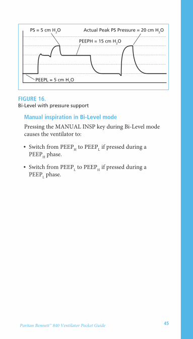
• If PSUPP + PEEPL is greater than PEEPH, all spontaneous breaths at PEEPL are augmented by the PSUPP setting, and all spontaneous breaths at PEEPH are augmented by (PSUPP + PEEPL – PEEPH). For example, if PEEPL = 5 cm H2O, and PEEPH = 15 cmH2O, and PSUPP = 15 cm H20:
• All spontaneous breaths at PEEPL are augmented by 15 cmH2O of pressure support (PSUPP + PEEPL) for a total pressure of 20 cm H2O.
• All spontaneous breaths at PEEPH are augmented by 5 cm H2O of pressure support (PSUPP + PEEPL – PEEPH) for a total pressure of 20 cm H2O (see Figure 16).
45Puritan Bennett™ 840 Ventilator Pocket Guide
manual inspiration in Bi-Level mode
Pressing the MANUAL INSP key during Bi-Level mode causes the ventilator to:
• Switch from PEEPH to PEEPL if pressed during a PEEPH phase.
• Switch from PEEPL to PEEPH if pressed during a PEEPL phase.
PS = 5 cm H2O
PEEPL = 5 cm H2O
PEEPH = 15 cm H2O
Actual Peak PS Pressure = 20 cm H2O
fiGUre 16. Bi-Level with pressure support

46 Puritan Bennett™ 840 Ventilator Pocket Guide
TUBe comPensaTion
Tube Compensation (TC) assists a patient’s spontaneous breath by delivering positive pressure proportional to the inspired flow, which overcomes the estimated resistance of an artificial airway. TC supports all spontaneous breaths for patients with an ideal body weight ≥ 7.0 kg (15.4 lb), and for endotracheal/tracheostomy tubes with an inside diameter (I.D.) of ≥ 4.5 mm. TC can be used within SPONT, BI-LEVEL or SIMV. With the Bi-Level option selected, TC supports spontaneous breaths at both PEEP levels.
Patient setup
To select TC option:1. Touch the VENT SETUP button on the lower screen.2. Touch the MODE button and turn the knob to select
either SPONT, BI-LEVEL or SIMV, all of which allow for TC to be selected as the spontaneous type.
3. Touch the SPONTANEOUS TYPE button and turn the knob to select TC.
4. Touch the CONTINUE button. The settings applicable to the selected mode, and for TC, appear on the lower screen.
5. Touch the on-screen button for each setting you wish to change, and then turn the knob to set the desired value (see Table 3 for tube I.D. and IBW). Proposed changes are highlighted. Press the CLEAR key above the knob to cancel any changes you’ve just made. Flashing arrows indicate TC settings.
noTe:If you select an I.D. that does not match the IBW, you must touch the Ok button to continue. The tube type and tube I.D. indicators flash if TC is a new selection.
6. When you have made the settings you want, press the ACCEPT key above the knob to apply the new settings, or the CLEAR key to cancel the last change.

47Puritan Bennett™ 840 Ventilator Pocket Guide
TaBle 3. Ideal body weight (IBW) and tube I.D.
iBW (kg) iBW (lb) eT/Trach i.d. eT/Trach i.d. (mm) (low) (mm) (high)
7-10 15-22 4.5 4.5
11-13 23-29 4.5 5.0
14-16 30-35 4.5 5.5
17-18 36-40 4.5 6.0
19-22 41-49 5.0 6.0
23-24 50-53 5.0 6.0
25-27 54-60 5.5 6.5
28-31 61-68 5.5 7.0
32-35 69-77 6.0 7.0
36 78-79 6.0 7.5
37-42 80-93 6.5 7.5
43-49 94-108 6.5 8.0
50-53 109-117 7.0 8.0
54-59 118-130 7.0 8.5
60 131-132 7.0 9.0
61-69 133-152 7.5 9.0
70 153-154 7.5 9.5
71-79 155-174 8.0 9.5
80-100 175-220 8.0 10.0
101-130 221-287 8.5 10.0
131-150 288-330 9.0 10.0

48 Puritan Bennett™ 840 Ventilator Pocket Guide
VenTilaTor self-TesTs
The Puritan Bennett™ 840 Ventilator has three self tests to verify microprocessor, pneumatic and circuit integrity. The tests include:
• Power on self-test (POST): A several-second test that automatically checks microprocessor function when you power up the ventilator.
• Short self-test (SST): A short and simple sequence of tests that verify proper ventilator operation. SST checks the patient circuit for leaks and measures circuit compliance.
• Extended self-test (EST): A more exhaustive test of ventilator integrity, designed to be run by a qualified service technician.
running ssT
Use SST to check the patient circuit for leaks and to calculate circuit compliance and resistance. Always rerun SST whenever you change the circuit type or the humidification type, or when you install a new or sterilized exhalation filter.
Incorrectly specifying the patient circuit type or humidification type (or changing either type after you’ve run SST) can affect the accuracy of compliance calculation and measured exhaled tidal volume. (You must rerun SST to change the circuit type. You can change the humidification type during ventilation by touching the OTHER SCREENS, then the MORE SETTINGS buttons.) Humidifier Volume allows you to mimimize inaccuracies due to a change in humidifier type.
WarninG

49Puritan Bennett™ 840 Ventilator Pocket Guide
➪ Ensure that the patient is not connected to the circuit and that the patient wye is unblocked.
Disconnect the ventilator from the patient before running SST. Running SST while the ventilator is connected to the patient can injure the patient.
➪ Turn the power switch (at the front of the ventilator) to the ON position. You can only run SST immediately after you turn on the ventilator.
➪ At the Ventilator Startup screen, touch SST, then press the TEST button (on the side of the ventilator) within five seconds. (Waiting longer than five seconds cancels SST.)
➪ At the Current SST Setup screen, select the patient circuit and humidification type (and humidifier volume, if applicable), then press ACCEPT.
➪ The ventilator automatically starts the test sequence. Some tests (SST flow sensor, Expiratory filter and Circuit resistance) require your intervention and will wait indefinitely for your response. Otherwise, you don’t need to do anything until a test result is ALERT or FAILURE, or SST is complete.
➪ As each test is performed, the SST Status screen shows test results (see Table 4).
To ensure reliable SST results, do not repeat an individual test with a different patient circuit if the test result is FAILURE or ALERT. If you suspect a defective patient circuit, restart SST from the beginning with a different patient circuit.
WarninG
WarninG

50 Puritan Bennett™ 840 Ventilator Pocket Guide
➪ You can touch EXIT SST during SST to halt testing. You can touch EXIT SST again to resume testing, or press ACCEPT to restart the ventilator (if SST has not detected an ALERT or FAILURE).
To ensure ventilation that correctly compensates for cir-cuit resistance and compliance, do not exit SST and begin normal ventilation until the entire SST has been success-fully completed with the circuit to be used attached.
WarninG
TaBle 4. Individual test results in SST
Nothing, unless prompted by the ventilator.
Touch one of these buttons, then press ACCEPT:
Repeat SST from the beginning.
Repeat the test.
Skip to the next test.
Touch one of these buttons, then press ACCEPT:
Repeat SST from the beginning.
Repeat the test.
Passed
ALERT
FAILURE
No problems found.
Test results not ideal, but not critical. SST halts.
A critical problem has been detected, and SST cannot complete until the ventilator passes the failed test.
if the test it means: do this: result is:
REPEAT
REPEAT
RESTART SST
RESTART SST
NEXT

51Puritan Bennett™ 840 Ventilator Pocket Guide
When all of the tests in SST are complete, the SST Status screen displays all individual test results and SST outcome. Table 5 summarizes overall SST outcomes and how to proceed in each case.
➪ To begin normal ventilation (if SST has not detected an ALERT or FAILURE), touch EXIT SST, then press ACCEPT. The ventilator reruns POST.
➪ The ventilator displays the Ventilator Startup screen. Confirm or change the last valid settings.
TaBle 5. Overall SST results
Touch one of these buttons, then press ACCEPT:
To exit SST and begin normal ventilation.
To repeat SST from the beginning.
Touch one of these buttons, then press ACCEPT:
To repeat SST from the beginning.
To override the alert, as allowed by your institution’s protocol, touch EXIT SST. Then press ACCEPT to begin normal ventilation.
Passed
ALERT
All tests passed.
One or more noncritical problems were detected. Follow your institution’s protocol for overriding an ALERT. Immediate service not required.
if the test it means: do this: result is:
EXIT SST
RESTART SST
RESTART SST
OVERRIDE

52 Puritan Bennett™ 840 Ventilator Pocket Guide
TaBle 5. Overall SST results (continued)
Restart SST with a different patient circuit. Touch
then press ACCEPT to repeat SST from the beginning.
If the failure persists, contact a qualified service technician.
FAILURE One or more critical problems were detected. The ventilator enters a ventilator inoperative state and cannot be used for normal ventilation until it passes SST. Service required.
if the test it means: do this: result is:
RESTART SST

53Puritan Bennett™ 840 Ventilator Pocket Guide
safeTy modes
The Puritan Bennett™ 840 Ventilator offers these safety modes:
Safety ventilation: If you attach a patient before completing setup, the ventilator alarms and begins safety ventilation. Safety ventilation delivers pressure control (PC) mandatory breaths with predetermined settings and a high pressure limit of 20 cm H2O until the setup is complete.
Apnea ventilation: The ventilator monitors the time from the start of one breath to the start of the next. If that time exceeds the operator-set apnea interval, the ventilator begins apnea ventilation according to operator-determined settings. Apnea ventilation continues until the patient initiates two consecutive breaths and the exhaled volume is equal to or greater than 50% of the delivered volume (autoreset). May also be manually reset by the operator.
Occlusion status cycling (OSC): The ventilator checks the patient circuit for severe occlusions during all modes of breathing to protect the patient from excessive airway pressures. If the ventilator detects a severe occlusion, it opens the safety valve and enters OSC. In OSC, the ventilator periodically attempts to deliver a pressure-based breath while monitoring for a severe occlusion. Normal ventilation resumes once the occlusion is corrected.
Idle mode (disconnect detection): Once the ventilator detects a patient circuit disconnect, it enters idle mode, in which the exhalation valve opens, idle flow (5 L/min flow at 100% O2, if available) begins, and breath triggering is disabled. The ventilator displays the length of time that the patient has been without ventilatory support. Once the ventilator confirms that the disconnect has been corrected, normal ventilation resumes.

54 Puritan Bennett™ 840 Ventilator Pocket Guide
The Puritan Bennett™ 840 Ventilator is also designed to enter emergency states (ventilator inoperative and safety valve open, SVO) under some circumstances. A ventilator inoperative condition always includes the SVO state, but an SVO state does not necessarily indicate a ventilator inoperative condition.
Ventilator inoperative: The ventilator declares a ventilator inoperative condition if a hardware failure or critical software error that could compromise safe ventilation occurs. In case of a ventilator inoperative condition, the ventilator enters the SVO state. To correct a ventilator inoperative condition, the ventilator must be turned off, then powered on again; at power on, a qualified service technician must run EST. The ventilator must pass EST before normal ventilation can resume.
SVO: The safety valve allows the patient to breathe room air unassisted when the ventilator is in the SVO state. The ventilator remains in the SVO state until the condition that caused the SVO state is corrected or, if the ventilator declared a ventilator inoperative condition, POST verifies that power levels to the ventilator are acceptable and that the major electronics systems are functioning correctly.
The ventilator enters the SVO state if a hardware or software failure occurs that could compromise safe ventilation, both air and oxygen supplies are lost or an occlusion is detected. In case of a malfunction that prevents software from opening the safety valve, there is also an analog circuit that opens the safety valve if system pressure exceeds 100 to 120 cm H2O.

55Puritan Bennett™ 840 Ventilator Pocket Guide
PreVenTiVe mainTenance
Table 6 summarizes maintenance intervals and procedures.
interval
Several times a day or as required by your institution’s policy
250 hours (or more often, if required)
Annually or after 100 autoclave cycles
Every two years or as necessary
Every 10,000 hours
Procedure
Check patient circuit for water buildup; empty and clean as necessary.
Inspect and check the resistance across inspiratory and expiratory filters before every use, after 15 days of continuous use in the exhalation limb or if you suspect excess resistance. (SST checks the resistance of the expiratory filter.)
Collector vial, water traps and drain bag: check and empty as needed.
Air inlet filter bowl: if cracked, replace bowl. If any sign of moisture is visible, remove ventilator from use and contact service or maintenance.
Clean compressor inlet filter.
Replace reusable inspiratory and expiratory bacteria filters. Sterilize between patients and circuit changes, or according to your institution’s policy. Sterilize before nondestructive disposal.
Replace oxygen sensor and BPS internal battery pack. (Must be replaced by a qualified service technician according to instructions in the Puritan Bennett™ 840 Ventilator Service Manual.)
Use appropriate preventive maintenance kit (preventive maintenance must be performed by a qualified service technician according to instructions in the Puritan Bennett 840 Ventilator Service Manual).
TaBle 6. Maintenance summary

COVIDIEN, COVIDIEN with logo, Covidien logo and positive results for life are U.S.
and internationally registered trademarks of Covidien AG. Other brands are trademarks of a
Covidien company. ©2008, 2011 Covidien. All rights reserved
11-VE-0259 VE07000
6135 Gunbarrel AvenueBoulder, CO 80301
800-635-5267 www.covidien.com