putting all together: using the artdeco approach in the ...12.pdf · putting all together: using...
TRANSCRIPT
Putting all together: using the ArtDecoapproach in the wine business domain
Eugenio Zimeo, Valentina Mazza, Giorgio Orsi, Elisa Quintarelli, AntonioRomano, Paola Spoletini, Giancarlo TretolaAlessandro Amirante, Alessio Botta, Luca Cavallaro, Domenico Consoli,Ester Giallonardo, Fabrizio Maria Maggi, Gabriele Tiotto
Abstract This chapter presents an approach for developing the models thatthe large-scale middleware infrastructure, designed in the ArtDeco project,uses to drive the behaviours of the information systems of a sample net-worked enterprise in the domain of wine production. This domain is suf-ficiently wide to cover many business aspects that highlight the ability ofthe proposed infrastructure to adapt itself to the evolving execution contextand to react to unexpected events with a very limited human interven-tion. However, the same approach has been experimented also in differentdomains, including fashion industry, value added services for telecommu-nication providers and logistics.
1 Introduction
With the advent of globalization, companies typically operate capturing thetrends of the market and delivering products that fit the needs of customers.Moreover, value chains should be faster to react to changes by using infor-mation systems that collect and process a large amount of data from the
Eugenio Zimeo, Giancarlo TretolaUniversity of Sannio e-mail: \{zimeo,tretola\}@unisannio.it
Valentina Mazza, Giorgio Orsi, Elisa QuintarelliPolitecnico di Milano e-mail: \{vmazza,orsi,quintarelli\}@elet.polimi.it
Paola SpoletiniUniversity of Insubria e-mail: [email protected]
Antonio RomanoScuola Superiore S. Anna di Pisa e-mail: [email protected]
Alessandro Amirante, Alessio Botta, Luca Cavallaro, Domenico Consoli, Ester Gial-lonardo, Fabrizio Maria Maggi, Gabriele TiottoGII Ph.D. School 2008, L’Aquila
435
436 Authors Suppressed Due to Excessive Length
business environment in order to satisfy the needs that emerge from thecustomers and to respond to anomalies that occur in the environment.
In the wine industry, the value chain typically consists of all the enterprisesand consumers that participate to the overall business process, starting fromwine design and ending with wine sales.The enterprises interact with the aimof improving their profits and reducing costs by producing the right amountof high-quality wine and by exploiting at the best the available resources inthe virtual organization.
Each enterprise runs internal processes, which aim at improving the benefitsfor the specific organisation, and participates to external processes, which aregenerated by the interaction of each enterprise with the other ones belongingto the network.
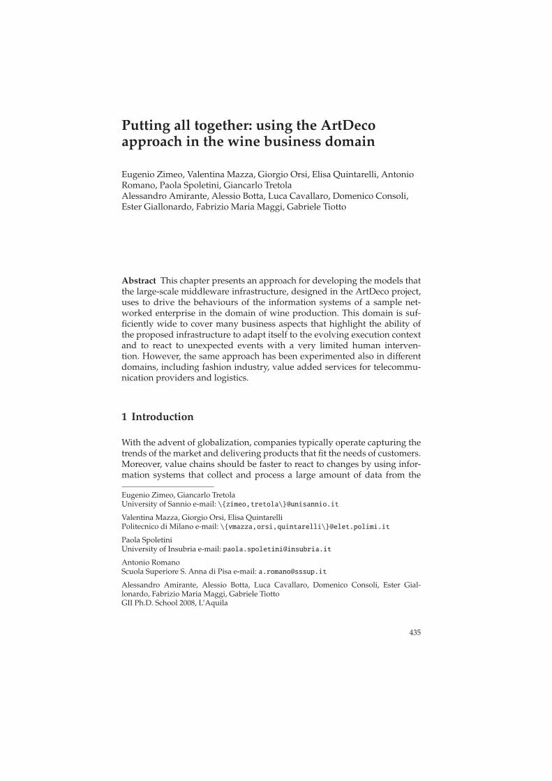
While wineries’ internal processes are typically orchestrated, as in ev-ery other manufacturing organisation, due to their well-known structure,external processes may be orchestrated (every supplier works for the wineproducer and interacts with it - see Fig. 1.a) or choreographed (suppliershave their own independent market and interact among them by forming apeer network - see Fig. 1.b), depending on the business models adopted.
Winery Marketing
Retailer
Carrier
Grape
grower
Material
producer
Marketing
Retailer
Carrier
Grape
grower
Material
producer
Winery
Fig. 1 (a) Centralised networked enterprise; (b) Decentralised networked enterprise.
While the former model is mostly adopted by specialised enterprises,the latter is better for not specialised ones since it is much more flexible andtolerant when the market is unstable (the enterprises can organise themselvesin networks to create new business opportunities). However, in both casescontextual events can alter a predefined business process so that it is able toevolve towards the successful termination in the new running conditions.
The structure of orchestrated processes can be changed as result of acentraslised decision, triggered by internal or external events. On the otherhand, the structure of decentralised processes can be altered as a result of adecentralised decision that leads to a new equilibrium point of the networkedenterprise to align the business to the changing market conditions (since inthis case, the external goal could be not known a priori).
Putting all together: using the ArtDeco approach in the wine business domain 437
Handling these events and changing the behavior of enterprises belongingto a network are not simple tasks (for related efficiency and cost dependency)without an adequate IT support that overcomes the current technologiesadopted by supply chains. The technologies and the methods developed inthe ArtDeco project could be a promising way to provide the desired ITsupport to help enterprises in improving their businesses and to survive inthe global market.
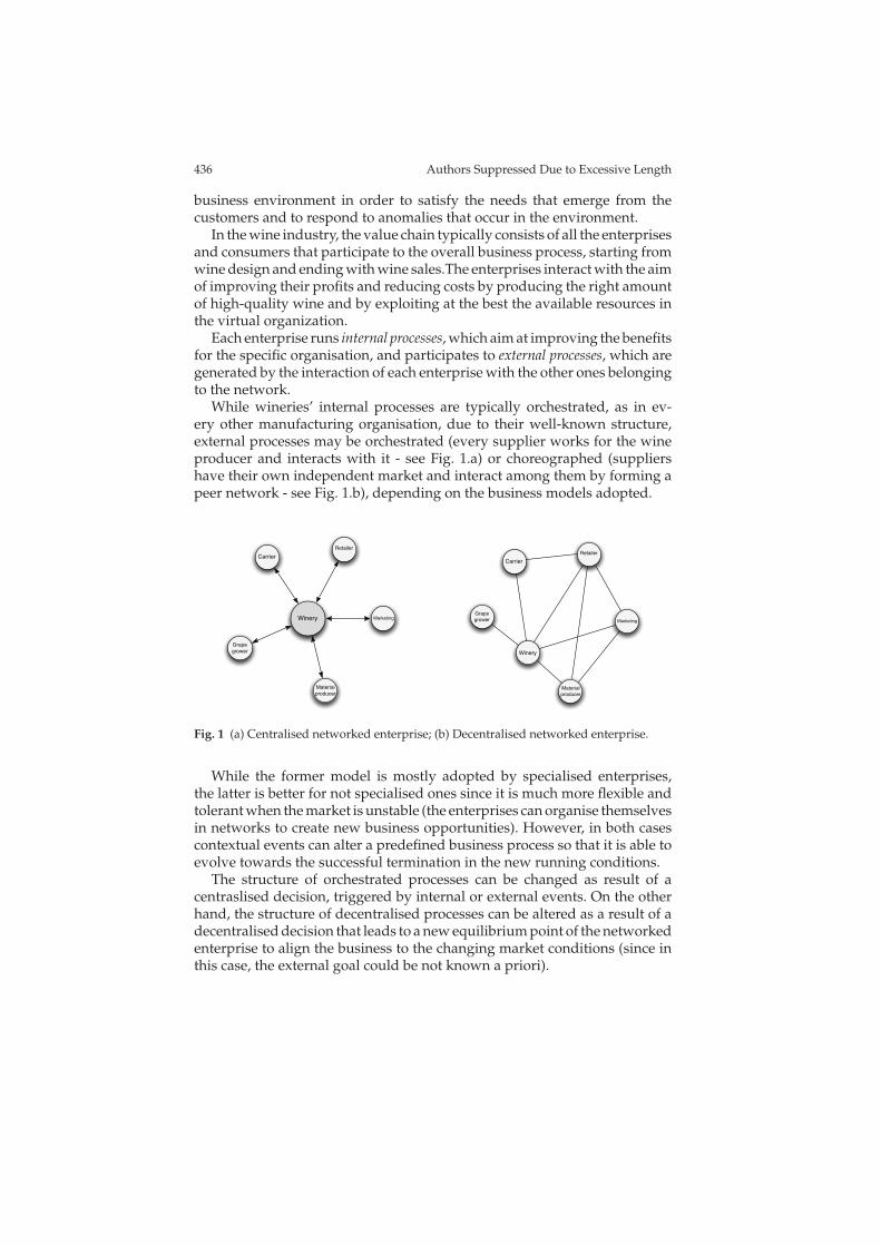
The overall ArtDeco system is composed of three main layers (see figure 2):business process, application, and logical layers. The high-level layer is in chargeof handling business processes, crossing different enterprises, through theirfunctional, non functional requirements, and active and reactive behaviours.The second layer represents the information systems distributed among thevalue chain partners that are able to execute workflows by providing datafrom different sources: data bases, data warehouses and wireless sensor networks.The lower level layer is responsible for abstracting the physical resourceswith the aim of enabling concrete actions and interactions with them.
Physical devices
abstraction
Local processes
Local information
Shared services and processes
Shared information
...
Company 1 Company 2 Company N
Physical devices
abstraction
Local processes
Local information
Physical devices
abstraction
Local processes
Local information
VirtualNetworked Enterprise
shared serv. / proc.
shared information
ArtDeco portal
Abort OK
Login....
ServicesMenu
Password...
Processlayer
Application layer
Abstractionlayer
Fig. 2 Networked Enterprise: the vertical view shows different abstraction processeswhereas the horizontal view highlights the owners of the different information systems.The enterprises involved in the network are federated through the registration in a busi-ness registry.
The basic paradigm to implement the Process Layer is Service OrientedComputing (SOC). With this paradigm, the value chain may become moreautomated basing the collaboration among participants on interactionsamong IT systems through the invocation of service operations, coordinatingand controlling complex processes in the form of distributed applications bymeans of workflow technology. However, basic SOC is not sufficient to en-sure the desired degree of autonomy since human beings are responsible toperform most of optimizing activities in more and more complex workflows.
Context awareness significantly enhances workflow technology by allow-ing business processes to adapt themselves to their environments exploitingthe opportunities and avoiding the problems that might emerge. However,this implies: (1) an increasing complexity of the analysis and the conceptionphases of processes’ lifecycle; (2) handling a large amount of data due to the
438 Authors Suppressed Due to Excessive Length
need for analyzing processes’ data during the execution; (3) run-time actionsto dynamically improve and adapt the business processes.
A further step to handle workflow complexity is proposed by autonomiccomputing 66. It has been already applied to automatically manage soft-ware systems by assigning to them the responsibility to self-manage theirresources and services, in order to stay operative and efficient when theexternal conditions change.
Self-management is typically based on the MAPE [7] cycle: Monitor theresources, Analyze the collected data, Plan the intervention, Execute the properactions. Monitored events can be originated internally to the organisationsby physical or virtual (human driven) sensors, or externally as the result ofthe actions of other enterprises or by other sources of the execution context.
This chapter discusses how do ArtDeco tools and methods can be used fordeveloping the models that drive the behaviours of the information systemsof a sample networked enterprise in the domain of wine production. The ap-proach requires enterprises re-engineering their business and organisationalmodels to work in a networked environment (see Part 1 of this book).
The information systems of these enterprises need to be enhanced withnew technology to handle the changes that occur in the business environ-ment during the execution of business processes, opportunely sensed bythese new infrastructures. Moreover, domain experts need novel design ap-proaches and validation techniques to model business processes that areable to survive to variations and anomalies arising in the business context,as proposed in Part 2.
Working in a open world [4] and with continuously changing conditionsrequires novel techniques to define data-models that can be successfully ex-ploited in heterogenous environments and in a variety of execution contexts.Moreover, new techniques to extract knowledge from the business environ-ment are needed, as described in Part 3. This knowledge regards whateverkind of information that can be collected by the middleware infrastructureand that can be usefully exploited to suggest a proper control onto the en-terprises’ choices.
A particular kind of information is the one coming from the physical en-vironment where the business processes take place. This information can beobserved by one or more networks of wireless sensors that are disseminatedin the physical space and whose data are propagated to the informationsystems for their analysis finalised to take proper decisions.
Driving the actions of the higher-level software infrastructure requireswireless networks to be programmed with expressive and powerful con-structs that are able to instruct networks to deliver only useful informationby reducing at minimum the possibility of faults due to excessive powerconsumption or other kinds of unexpected events, as discussed in Part4.
The remaining part of the chapter is organized as follows. Section 2 de-scribes and models the scenario used in this chapter to show the role ofeach technology or methodology developed in the ArtDeco project. Section
Putting all together: using the ArtDeco approach in the wine business domain 439
3 presents an integrated view of the middleware architecture and how appli-cations for it can be modelled, programmed, executed and verified. Section4 describes the school organised during the project and reports on lessonslearnt from the Ph.D. students that attended the school. Finally, Section 5concludes the chapter.
2 Application scenario and modelling
The scenario presented in 1 is detailed in this section with the aim of iden-tifying some demonstration cases of the results produced in the ArtDecoproject. The focus of the scenario is around a hypothetical winery (namedGialloRosso)1 that operates as main contractor in a networked enterprise.
The winery uses IT technologies in order to increase wine quality andto reduce production and distribution costs. It interacts with other companiesthat provide materials, transportation, storage and distribution. The wholevalue chain is able to adapt its business processes to the evolution of theenvironment with the aim of satisfying the requirements defined duringthe wine design phase. In particular, wine quality depends on all the phasesof the wine production: grapes cultivation, wine maturation and distribution.However, the major contribution to quality depends on the basic ingredientof wine: the grapes.
The GialloRosso winery handles several vineyards that are monitoredduring the cultivation to provide the agronomist, the oenologist and theinformation systems with sufficient data for avoiding irrecoverable damagesto the grapes, ensuring their high quality, and controlling the amount ofgrapes useful for producing the desired wine. However, if critical damagesoccur, the winery is able to replace the harvesting with an order from otherwineries of specific kinds of grapes, with a competitive price, that ensureproducing the amount of wine that the Giallorosso winery is able to sell(data that can be extracted from the statistics of the winery or from themarket trend).
The winery is also interested in monitoring wine during storage in cel-lars since this information helps the oenologist and the system to monitorwine aging. Moreover, wine temperature during transportation should bemonitored to reduce losses of quality and consequent returns.
In addition to information needed for ensuring wine quality, the winery isalso interested in reducing the final cost of a wine bottle in order to increasesales for medium-quality wines or to improve the saving for high-qualitywines. To this end, many inefficiencies should be eliminated by revising the
1 The information about wine life-cycle reported in this chapter is inspired by discussionsthat we had with two sicilian wine producers: Donnafugata and Planeta. The scenariodepicted is a collection of fragments (not complete) of real business processes that highlightthe main innovations obtained as a result of the ArtDeco project.
440 Authors Suppressed Due to Excessive Length
organisational models of the winery and its cooperation with other enter-prises that are involved in the business scenario. For example, transportationof wine could be optimised by coordinating the planning of several wineriesthat are interested in delivering the final product to the same distribution orselling point.
To achieve the desired level of flexibility and control, the GialloRossowinery adopts both traditional (legacy) and novel IT technologies to handleits internal processes and the interaction with the external environment.This way, the application logic of existing IT systems is integrated by usingworkflow management systems and accessed by human operators through aportal, which enables the sharing of both information and services inside thewinery and outside with other enterprises that belong to the same businessnetwork.
2.1 BPMN modelling
All the IT systems of the winery are handled in a uniform way through aset of processes (each one modelling the wine life-cycle for each year). Inthe following, we mainly refer to one of this process (named main process)that characterises the life cycle of the current year (nevertheless, interactionswith other processes related to other years could be useful in some cases).The human operators involved are agronomist, oenologist, farmer, worker, ware-houseman, quality manager, etc..
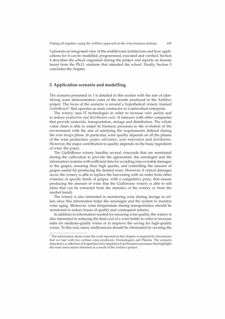
The main process can be decomposed in some sub-processes (see Fig. 3)that are related to the main phases of wine life-cycle: cultivation, productionand distribution. This process is executed and controlled by a workflow man-agement system that is able to interact with the environment though severalperipheral systems: physical and logical sensors, and physical and logicalactuators.
Before starting such a process, information from the marketing is neededto estimate the kind and the related amount of wine to produce for differentgeographic areas, which are the commercial target of the winery. This mar-keting information represents the input to derive the kind and the amountof grapes to cultivate in the first part of the main process.
Fig. 3 Main process of the winery
Putting all together: using the ArtDeco approach in the wine business domain 441
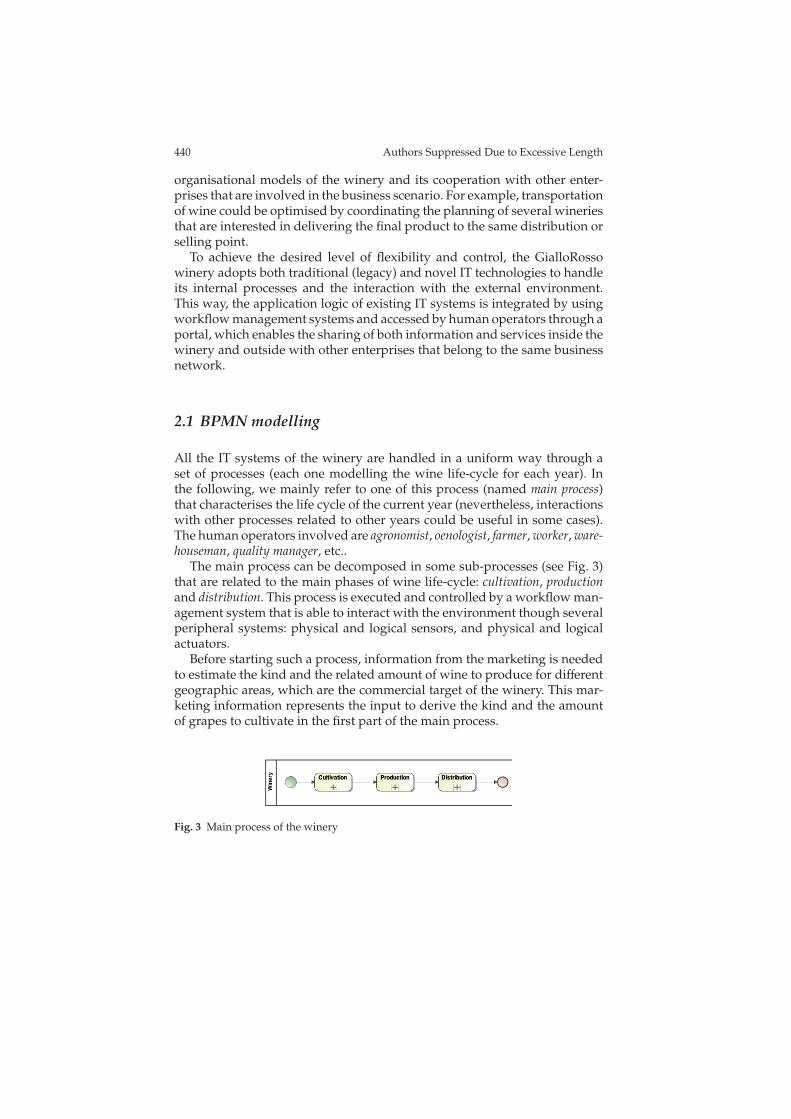
Fig. 4 Cultivation sub-process
The cultivation phase is handled by grape growers that can be internal to thewinery or external organisations. Anyway, this phase is organised accordingto a process composed of sub-processes that reflect the phases of the grapelife-cycle: vegetative rest, sprouting, flowering, accretion, and harvesting.
Each one of this sub-process is split into as many sub-processes as thereare vineyards to manage and are assigned to operators. The activities of theseoperators are organised on daily basis and can be changed as consequenceof unexpected events. For example, during vegetative rest, processes to beperformed daily may be those shown in Fig. 4.
The events that can occur during the different phases of the grapes life-cycle and some possible recoverable actions are reported in Table 2.1, illus-trated in the introduction of this book. The events are tied to observablephenomena that are monitored though specific sensors.
The values monitored are assigned to high-level parameters that are usedto identify some critical conditions, such as: (1) hailstorm has destroyed thegrapes of the vineyard, (2) rain does not allow for harvesting, (3) presence of powderymildew. For every phenomenon, a possible corrective action can be defined
442 Authors Suppressed Due to Excessive Length
by using reactive rules. For example, in case (1), the system could solve theproblem by buying grapes from other producers. In case (2), the systemdelays or suspends the harvest, and in (3) it plans the intervention of theagronomist.
During the production phase, the measured parameters can be used to as-sess changes in the mix of grapes used in previous years. A wide array ofsensors monitors the environmental conditions of cellars. Also the fermen-tation phase is controlled with periodical chemical analysis that allows forassessing how the composition of the wine is evolving. When the wine isin bottles, monitoring humidity and temperature is important to ensure agood preservation: wine, in fact, must not suffer of temperature fluctuationshigher than 5 degrees, and humidity fluctuations higher than 5%.
Fig. 5 Distribution sub-process
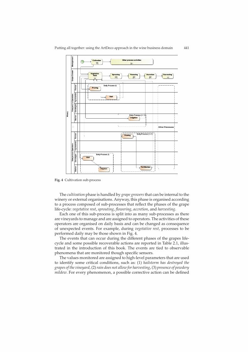
As a consequence, during the distribution phase, these two attributes maybe used to substantially influence the choice of the carrier performed by thewinery. These parameters, in fact, are measured and exploited for evaluatingthe quality of the previous subcontractors’ performances. Temperature andhumidity of the package during transportation are recorded in data loggersfor subsequent analyses. Fig. 5 shows the distribution sub-process. It is aimedto discover and to select a carrier for delivering the wine bottles, on thebasis of the quality of the delivery service. During the delivering activity,temperature and humidity are measured and stored. Process performance isassessed and used to subsequently update the carrier reputation.

Putting all together: using the ArtDeco approach in the wine business domain 443
3 Middleware architecture and programming
Due to the complexity of the interactions and the need for handling unex-pected events, existing technology for managing business processes are nolonger sufficient for networked enterprises working in the global market.Therefore, we consider having a new technology substrate in each enter-prise that contributes to create a virtual information system able to drive theactors of the whole network.
The complex mix of information systems adopted at application layer ishard to manage without a support from the system itself. In this direction,autonomic computing, data integration and, in particular, the techniquesand the technologies discussed in the previous chapters represent promisingsolutions to handle such kind of complexity.
Centralised and decentralised
coordination system
WSN
RFID network
WSN
WSN
Knowldege extraction and management system
Carrier
Winery - production: monitoring
Co
nte
xt M
on
ito
rin
g WSN
WSN
Winery - cultivation: monitoring
Kn
ow
led
ge
Extr
actio
n
Winery: information system
...
...
Other information sources
Interactions
ExternalWinery
OtherSupplier
InformationSystem
DB
Web Portal
Se
rvic
e in
vo
ca
tio
ns
Se
rvic
e in
vo
ca
tio
ns
Co
nte
xt E
ve
nts
Me
ssa
gin
g
Inter Enterprise Service Bus Enterprise Service BusInter Enterprise Service BusInter Enterprise Service Bus Enterprise Service BusEnterprise Service Bus
Co
nte
xt E
ve
nts
Me
ssa
gin
g
Web Portal
Winery: Portal
Retailer
OtherSupplier
Other supplier
Business registry
WS
N d
ata
a
cq
uis
itio
nsu
bsyste
m
WS
N d
ata
a
cq
uis
itio
nsu
bsyste
m
WS
N d
ata
a
cq
uis
itio
nsu
bsyste
m
Fig. 6 Architecture of the ArtDeco System deployed in the networked enterprise
It is worth noting that the results proposed in the previous chapters ofthis book contributed to address some scientific issues that represent theenablers of a new-generation middleware, which will be described and detailedin the next sub sections. However, several additional aspects (security, privacy,transactions management, performance, and scalability), which make it possible
444 Authors Suppressed Due to Excessive Length
to adopt such a middleware in real deployments, have not been addressedduring the ArtDeco project but they will be addressed in future work.
The main components of the current design of the middleware infras-tructure are (see figure 6): (1) the autonomic sub-system for centralised anddecentralised coordination of actions; (2) the knowledge extraction and man-agement sub-system; (3) the wireless sensors networks and the related mid-dleware for data acquisition.
These components are connected by exploiting some buses: an enter-prise bus is used for connecting components inside enterprises and an inter-enterprise bus is used for connecting components belonging to different or-ganisations. These buses are also structured in order to enable two differentkinds of interactions: event-driven, to handle events from the business envi-ronment, and invocation-based, to ask for the execution of specific servicesprovided by the middleware components. The current implementation ofthese buses is only for proof of concepts; therefore, a significative workcould be devoted in the future to enhance existing enterprise service buseswith the features identified during the ArtDeco project.
Developing applications for the ArtDeco middleware requires the defini-tion of internal processes and their relationships with external informationsystems, global processes that aims at finding new business collaborations,data acquisition and management from different sources. In the next sub-sections, the three main sub-systems shown in Fig. 6 are detailed and dis-cussed as concerning their roles and programming features.
3.1 Handling internal processes and their interactions withexternal systems
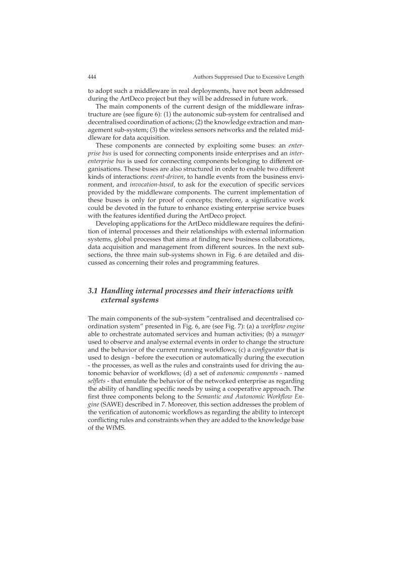
The main components of the sub-system ”centralised and decentralised co-ordination system” presented in Fig. 6, are (see Fig. 7): (a) a workflow engineable to orchestrate automated services and human activities; (b) a managerused to observe and analyse external events in order to change the structureand the behavior of the current running workflows; (c) a configurator that isused to design - before the execution or automatically during the execution- the processes, as well as the rules and constraints used for driving the au-tonomic behavior of workflows; (d) a set of autonomic components - namedselflets - that emulate the behavior of the networked enterprise as regardingthe ability of handling specific needs by using a cooperative approach. Thefirst three components belong to the Semantic and Autonomic Workflow En-gine (SAWE) described in 7. Moreover, this section addresses the problem ofthe verification of autonomic workflows as regarding the ability to interceptconflicting rules and constraints when they are added to the knowledge baseof the WfMS.
Putting all together: using the ArtDeco approach in the wine business domain 445
Workflow Engine
Control Layer
Binding Layer
Interaction Layer
Me
ta W
ork
flo
w E
lem
en
ts
MW
P
WS WSWS WS
ESB
Engine Monitor
QoS
Monitor
WS
WSN
WS
RFID
WS WS
Manager
Composer Binder Interactor
Configurator
e-Context
Monitor
Business Environment
Rule Ed
MWP
Goal AbstractProcess
ConcreteProcess
Rule
Context Ed
Context
SAWE
Client
HTTP SOAP
Portal
Parser
Ad
min
istr
atio
n
Inte
rfa
ce
Rules
Working
memory
ProcessManager
Selflet A
Selflet B
Selflet C
Enterprise A
Enterprise B
Enterprise C
Selflet E
Business Environment
Selflets
Fig. 7 Coordination system architecture
3.1.1 Centralised management of a networked enterprise
In this sub-section, we discuss some examples of autonomic workflows byusing an orchestrated view. The workflows are mainly referred to the internalprocesses of the winery even though some considerations are reported asregarding the interactions with other enterprises belonging to the network.These interactions typically involve the conversation among the informationsystems of different enterprises by using web services as enabling technology.
As reported in chapter 7, programming an autonomic workflow requiresthe definition of two separate sets of instructions: a typical flow of control,following an imperative model, and an event-driven behavior, based on adeclarative language. In the following, the two parts of some sample work-flows related to the scenario presented in Section 2.1 are illustrated.
Programming the workflow engine
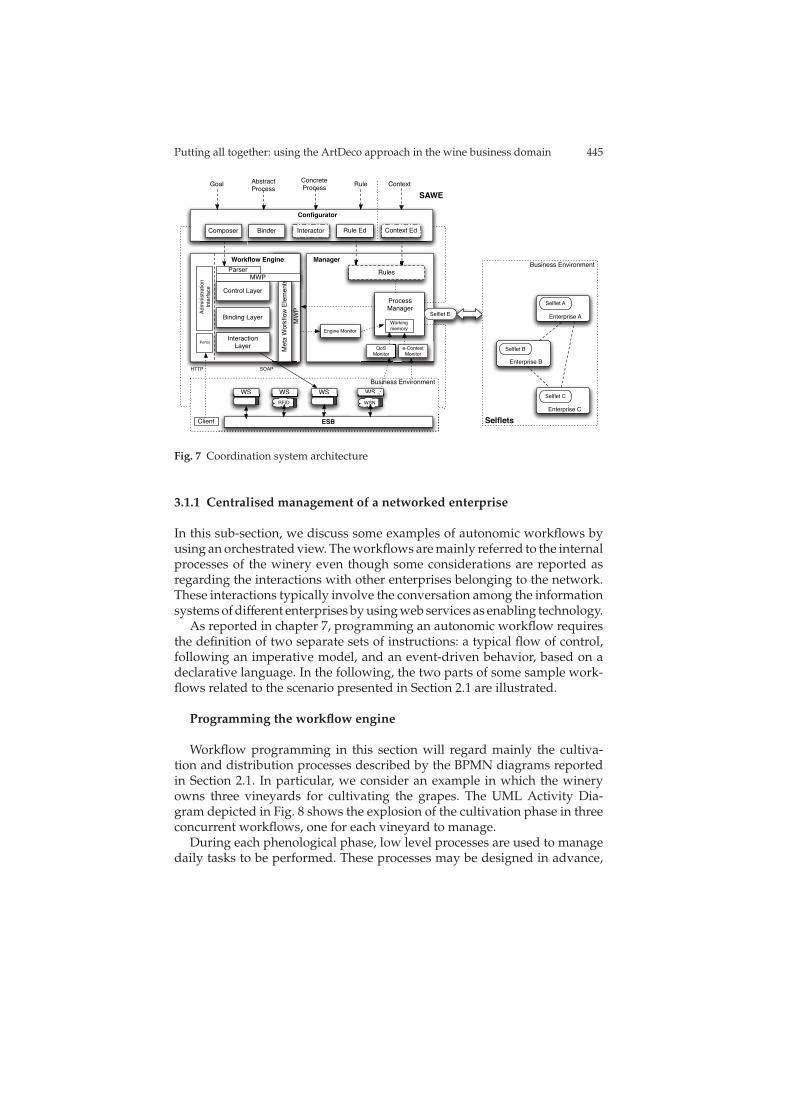
Workflow programming in this section will regard mainly the cultiva-tion and distribution processes described by the BPMN diagrams reportedin Section 2.1. In particular, we consider an example in which the wineryowns three vineyards for cultivating the grapes. The UML Activity Dia-gram depicted in Fig. 8 shows the explosion of the cultivation phase in threeconcurrent workflows, one for each vineyard to manage.
During each phenological phase, low level processes are used to managedaily tasks to be performed. These processes may be designed in advance,
446 Authors Suppressed Due to Excessive Length
Fig. 8 Activity diagram representing the cultivation process
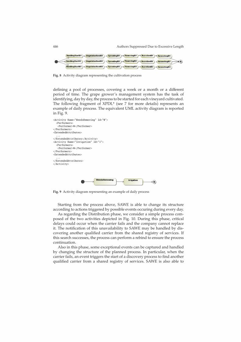
defining a pool of processes, covering a week or a month or a differentperiod of time. The grape grower’s management system has the task ofidentifying, day by day, the process to be started for each vineyard cultivated.The following fragment of XPDL* (see 7 for more details) represents anexample of daily process. The equivalent UML activity diagram is reportedin Fig. 9.
<Activity Name="WeedsRemoving" Id="0">
<Performers>
<Performer>0</Performer>
</Performers>
<ExtendedAttributes>
...
</ExtendedAttributes>/Activity>
<Activity Name="Irrigation" Id="1">
<Performers>
<Performer>0</Performer>
</Performers>
<ExtendedAttributes>
...
</ExtendedAttributes>
</Activity>
Fig. 9 Activity diagram representing an example of daily process
Starting from the process above, SAWE is able to change its structureaccording to actions triggered by possible events occuring during every day.
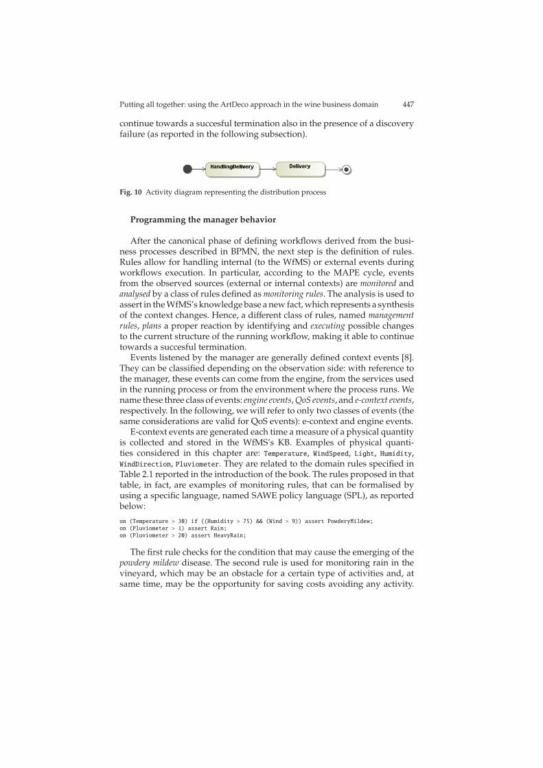
As regarding the Distribution phase, we consider a simple process com-posed of the two activities depicted in Fig. 10. During this phase, criticaldelays could occur when the carrier fails and the company cannot replaceit. The notification of this unavailability to SAWE may be handled by dis-covering another qualified carrier from the shared registry of services. Ifthis search successes, the process can perform a rebind to ensure the processcontinuation.
Also in this phase, some exceptional events can be captured and handledby changing the structure of the planned process. In particular, when thecarrier fails, an event triggers the start of a discovery process to find anotherqualified carrier from a shared registry of services. SAWE is also able to
Putting all together: using the ArtDeco approach in the wine business domain 447
continue towards a succesful termination also in the presence of a discoveryfailure (as reported in the following subsection).
Fig. 10 Activity diagram representing the distribution process
Programming the manager behavior
After the canonical phase of defining workflows derived from the busi-ness processes described in BPMN, the next step is the definition of rules.Rules allow for handling internal (to the WfMS) or external events duringworkflows execution. In particular, according to the MAPE cycle, eventsfrom the observed sources (external or internal contexts) are monitored andanalysed by a class of rules defined as monitoring rules. The analysis is used toassert in the WfMS’s knowledge base a new fact, which represents a synthesisof the context changes. Hence, a different class of rules, named managementrules, plans a proper reaction by identifying and executing possible changesto the current structure of the running workflow, making it able to continuetowards a succesful termination.
Events listened by the manager are generally defined context events [8].They can be classified depending on the observation side: with reference tothe manager, these events can come from the engine, from the services usedin the running process or from the environment where the process runs. Wename these three class of events: engine events, QoS events, and e-context events,respectively. In the following, we will refer to only two classes of events (thesame considerations are valid for QoS events): e-context and engine events.
E-context events are generated each time a measure of a physical quantityis collected and stored in the WfMS’s KB. Examples of physical quanti-ties considered in this chapter are: Temperature, WindSpeed, Light, Humidity,WindDirection, Pluviometer. They are related to the domain rules specified inTable 2.1 reported in the introduction of the book. The rules proposed in thattable, in fact, are examples of monitoring rules, that can be formalised byusing a specific language, named SAWE policy language (SPL), as reportedbelow:
on (Temperature > 30) if ((Humidity > 75) && (Wind > 9)) assert PowderyMildew;
on (Pluviometer > 1) assert Rain;
on (Pluviometer > 20) assert HeavyRain;
The first rule checks for the condition that may cause the emerging of thepowdery mildew disease. The second rule is used for monitoring rain in thevineyard, which may be an obstacle for a certain type of activities and, atsame time, may be the opportunity for saving costs avoiding any activity.
448 Authors Suppressed Due to Excessive Length
The third rule is used for identifying heavy rain, which, if is coupled withhailstorm, can cause heavy damage to the vineyard.
The same approach can be followed when measures are referred to virtualsensors that are able to collect more complex and aggregate measures. Anexample of such a sensor is a feedback from a human being related to anobservation of the external environment. The rule reported below uses aphysical quantity, named GrapesQuality, monitored by a virtual sensor toassert that the quality of the vineyard identified by ID1 is not able to producehigh-quality grapes and therefore harvesting is not possible.
on (GrapesQuality.<ID1>==LOW) assert NotHarvesting.<ID1>;
The monitoring rules typically are used to generate higher level events,possibly coupled with management rules. These rules exploit meta-operationsto change the current structure of the running workflow (see chapter 7 forthe complete semantics of the meta-operations), as exemplified below:
on (PowderyMildew) add Spraying;
on (Rain) drop Spraying;
on (Rain) drop Irrigation;
on (HeavyRain) add AgronomistVisit;
Powdery mildew insurgence is contrasted using appropriate chemical sub-stances to be sprayed in the vineyard (thus, an activity - Spraying - is addedto the workflow). In another situation, rain may be an obstacle for sprayingwhich have to be dropped while, at same time, it is an opportunity that maybe exploited for avoiding to perform irrigation. Heavy rain requires par-ticular attention and call for planning an agronomist visit to supervise thephenomenon and, if it is the case, introducing in the system information thatmay cause the generation of an event signaling low quality for some grapes.
As regarding the example on grapes quality, the id of the vineyard in-terested by low quality is obtained by exploiting specific info provided bythe agronomist. This info is used to extract statistical information on grapesvariety and amount from the database and consequently the harvest activityis replaced by buying.
on (NotHarvesting.<ID1>) replace Harvesting.<ID1> with Buying.<ID1>;
It is worth noting that the angular brackets are used to refer to an implicitinformation used to correlate the replacing and the replaced activities.
Management rules have to be verified against a set of high level con-straints, expressed in SPL. The following constraints can be used for sup-porting the autonomic adaptation of the cultivation process, in order to avoidinconsistency at run-time. They allow for reacting to events and, at same time,to guarantee workflow correctness. The symbol ->!means mutual exclusionbetween the two involved activities and <->means dependence between theinvolved activities.
AgronomistVisit ->! Irrigation
OenologistVisit <-> Harvesting
Buying ->! Harvesting
Putting all together: using the ArtDeco approach in the wine business domain 449
The first constraint states that it is not possible to have, in the same han-dling process (that spans for a day), an agronomist visit and an irrigationactivity. The second constraint states that during harvesting process, an oe-nologist visit is needed for assessing grapes quality. The last constraintssuggests that buying of grapes is permitted only if harvesting is not possible(for a whole vineyard in the example).
Both monitoring and management rules expressed in SPL are currentlytranslated in CLIPS rules, for their execution in a Jess engine. In the following,the translation of the management rules for the daily processes previouslydescribed is reported:
(assert (ADD (event PowderyMildew) (activity Spraying)))
(assert (DROP (event Rain) (activity Irrigation)))
(assert (DROP (event Rain) (activity Spraying)))
(assert (ADD (event HeavyRain) (activity AgronomistVisit)))
Translation is based on templates to factorise the common behaviour of theoperation and to perform verification before executing the adaptation. Thefollowing fragment of code shows an example for the ADD meta-operation.
(deftemplate ADD (slot event) (slot activity))
(defrule ADD-Management
(ADD (event ?e) (activity ?a))
(ContextEvent {type == CONTEXT}
(name ?e) (sourceId ?sId) (processId ?pId) (value ?e)
(measurementUnit ?mu) (description ?d) (areaId ?aId))
(not (ConstraintViolation {type == Mutex}
(activityA ?a) (activityB ?aB) (procId ?pId)))
(not (ConstraintViolation {type == Dependence}
(activityA ?a) (activityB ?aB) (procId ?id))))
=>
(call ?manager addActivity ?a ?pId)
)
In the Distribution process, it is possible that a carrier is not available,i.e. the static binding defined at the beginning of the process is not satisfiedand/or there is no service in the registry able to satisfy the needed functional-ity. If this happens, a binding failure occurs. The related event is propagatedto the management level for its processing by firing the following manage-ment rules.
on (BindingFailure) compose <BindingFailure>.service
on (ComposingSuccess) invoke <ComposingSuccess>.service
The first rule is used to request the composition of the failed service toexternal systems supporting the workflow execution: the semantic func-tional description of the service is used for defining the service that must becomposed.
The second rule is used to receive the result of the composition, as per-formed by the external system and to invoke the composed service. Thisalters the executing process, replacing the failed activity with another onethat is in charge of invoking the received composition. Also in these cases,the angular brackets refer to implicit information used to correlate the events
450 Authors Suppressed Due to Excessive Length
and the actions (in the example, the service description used for the compo-sition is extracted from the triggering event of type BindingFailure).
It is worthy noting that also the composition may fail. In this case, anotherlevel of autonomic action could be performed (not described in this examplebut available in SAWE): re-planning of the remaining process, from the currentstate to the goal. This recovery action is able to find an alternative flow ofactivities able to reach the process objective. This kind of failure recovery isnot always possible. It depends a lot on the kind of workflow executed andon the availability of equivalent services.
When every failure mechanism provided by SAWE fails, a notification issent to the human manager.
3.1.2 Decentralised management of networked enterprises
During the execution, the workflow requires the invocation of a service fora delivery activity. Such activity could be accomplished either by a deliverycompany, or by some other wineries belonging to the network of enterprisessubscribed in the service registry. It is possible that, no service is available inthe registry and as a consequence, no binding is found for that activity anda binding failure occurs.
In the Artdeco architecture, different components could support the work-flow engine in order to offer an autonomic behaviour; in particular the work-flow of the GialloRosso winery (and the workflow of the others enterprisesbelonging to the network) can be bound to a SelfLet 6 able to react tochanges in the surrounding environment and make decision on the basis ofthe sensed context.
Reasoning on the sensed context means managing information about theinternal and/or the external execution environment. In particular, a SelfLetcould access to the information regarding other enterprises belonging to thenetwork. Such information could be related to a particular service offeredfor a certain time by an enterprise and, due to its nature, not possible to findin the registry. In fact, while the workflow is mainly thought to access tostable information valid for a long period of time (generally stored in a reg-istry), the SelfLets are conceived to be more suitable to observe and to reactto the continuously changing environment in which the network evolves;in particular, the SelfLets are able to access to information having a ”tem-porary” validity obtained reasoning on the current status of the enterprisescomposing the network.
Since the workflow is not able to identify any service satisfying its needs,it generates an event requesting the intervention of the SelfLet. It receivesthe description of the problem and reacts to the event: on the basis of thegathered information it can decide, which is the best solution optimizingcost and efficiency requirements. In particular, it could decide to contact adelivery company or another winery and could inform the workflow of the
Putting all together: using the ArtDeco approach in the wine business domain 451
result of the decision. Thanks to this, the workflow of GialloRosso is able tocontinue the execution without failures.
While a binding failure, occurring during the execution of a traditionalworkflow, implies a human intervention to decide the next step or the abortof the process, in the Artdeco workflow the binding failure suspends thefailed task while the other activities currently executing can continue with-out problems. In such a way, the workflow engine could access to externalresources in order to overcome the failure; due to this, the workflow switchesin the ”composing” mode and communicates with the other components ableto accomplish the needed task.
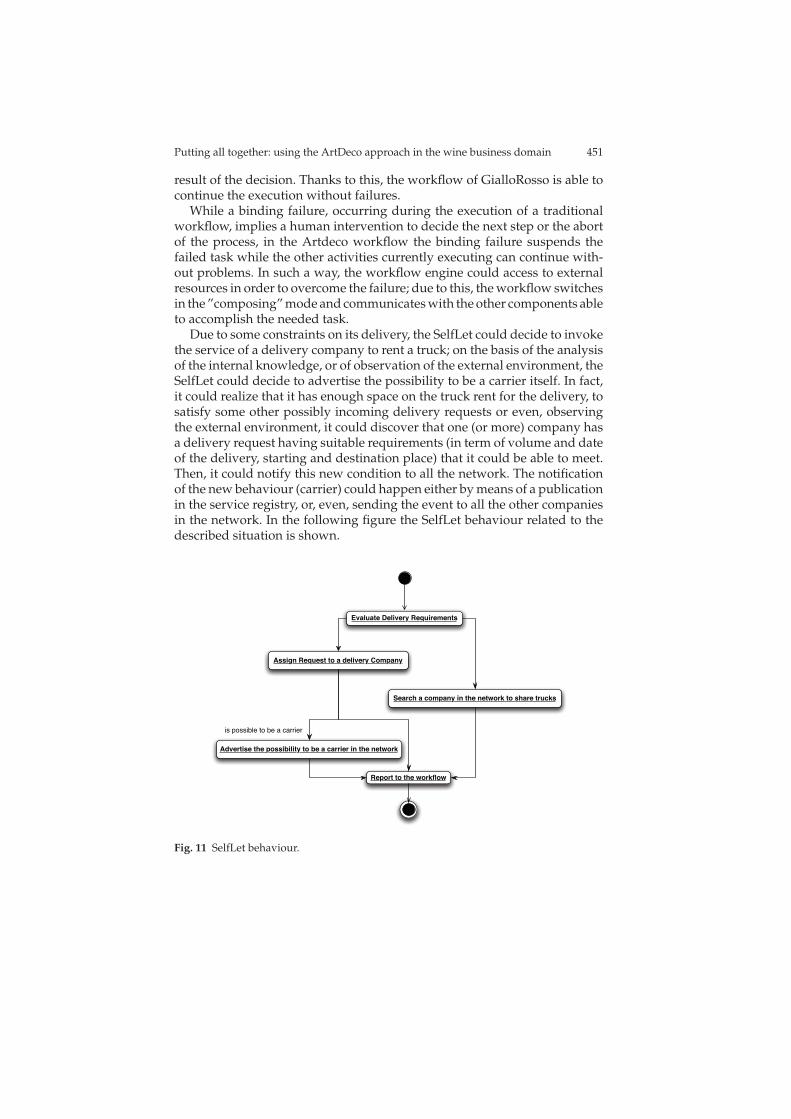
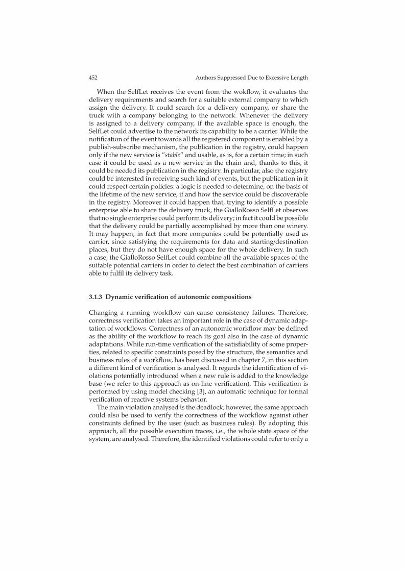
Due to some constraints on its delivery, the SelfLet could decide to invokethe service of a delivery company to rent a truck; on the basis of the analysisof the internal knowledge, or of observation of the external environment, theSelfLet could decide to advertise the possibility to be a carrier itself. In fact,it could realize that it has enough space on the truck rent for the delivery, tosatisfy some other possibly incoming delivery requests or even, observingthe external environment, it could discover that one (or more) company hasa delivery request having suitable requirements (in term of volume and dateof the delivery, starting and destination place) that it could be able to meet.Then, it could notify this new condition to all the network. The notificationof the new behaviour (carrier) could happen either by means of a publicationin the service registry, or, even, sending the event to all the other companiesin the network. In the following figure the SelfLet behaviour related to thedescribed situation is shown.
Report to the workflow
Advertise the possibility to be a carrier in the network
Assign Request to a delivery Company
Evaluate Delivery Requirements
Search a company in the network to share trucks
is possible to be a carrier
Fig. 11 SelfLet behaviour.
452 Authors Suppressed Due to Excessive Length
When the SelfLet receives the event from the wokflow, it evaluates thedelivery requirements and search for a suitable external company to whichassign the delivery. It could search for a delivery company, or share thetruck with a company belonging to the network. Whenever the deliveryis assigned to a delivery company, if the available space is enough, theSelfLet could advertise to the network its capability to be a carrier. While thenotification of the event towards all the registered component is enabled by apublish-subscribe mechanism, the publication in the registry, could happenonly if the new service is ”stable” and usable, as is, for a certain time; in suchcase it could be used as a new service in the chain and, thanks to this, itcould be needed its publication in the registry. In particular, also the registrycould be interested in receiving such kind of events, but the publication in itcould respect certain policies: a logic is needed to determine, on the basis ofthe lifetime of the new service, if and how the service could be discoverablein the registry. Moreover it could happen that, trying to identify a possibleenterprise able to share the delivery truck, the GialloRosso SelfLet observesthat no single enterprise could perform its delivery; in fact it could be possiblethat the delivery could be partially accomplished by more than one winery.It may happen, in fact that more companies could be potentially used ascarrier, since satisfying the requirements for data and starting/destinationplaces, but they do not have enough space for the whole delivery. In sucha case, the GialloRosso SelfLet could combine all the available spaces of thesuitable potential carriers in order to detect the best combination of carriersable to fulfil its delivery task.
3.1.3 Dynamic verification of autonomic compositions
Changing a running workflow can cause consistency failures. Therefore,correctness verification takes an important role in the case of dynamic adap-tation of workflows. Correctness of an autonomic workflow may be definedas the ability of the workflow to reach its goal also in the case of dynamicadaptations. While run-time verification of the satisfiability of some proper-ties, related to specific constraints posed by the structure, the semantics andbusiness rules of a workflow, has been discussed in chapter 7, in this sectiona different kind of verification is analysed. It regards the identification of vi-olations potentially introduced when a new rule is added to the knowledgebase (we refer to this approach as on-line verification). This verification isperformed by using model checking [3], an automatic technique for formalverification of reactive systems behavior.
The main violation analysed is the deadlock; however, the same approachcould also be used to verify the correctness of the workflow against otherconstraints defined by the user (such as business rules). By adopting thisapproach, all the possible execution traces, i.e., the whole state space of thesystem, are analysed. Therefore, the identified violations could refer to only a

Putting all together: using the ArtDeco approach in the wine business domain 453
subset of the complete set of traces. This suggests to not removing potentiallyconflicting rules from the knowledge base but to move the verification torunt-time. On the other hand, if the current set of rules satisfies the desiredproperties, run-time verification is not needed.
On-line verification has been used for analysing the cultivation handlingphase, considering also the adaptation rules. The model checking has beenperformed using the following steps:
1. Modelling: target system is formally described, using the verification toolformalism;
2. Specification: temporal logic is used for specifying system properties;3. Verification: the model is checked against the property using the engine
of the model checker.
The case study workflow has been evaluated using two different ModelChecking approaches. The first one is the symbolic model checker NuSMV [17],derived from SMV (Symbolic Model Verifier). The model has been realizedusing Petri nets for representing the workflow, as described in the XPDL*,and the possible adaptation, as described in the management rules, sincePetri nets are easily translated in the checker input language. Then, thebranching temporal logic CTL has been used for stating the correct behav-ior that we want to guarantee with the specification of the workflow and itsadaptation rules. The automatic verification of the model has given a positiveresult: the workflow and the policy rules are correct against the properties.
The second approach has used the model checker Spin [6]. In this casethe process has been modeled using a finite state machine with a state foreach phenological phases of the grapes. Additional states has been used formodeling alarm states, which describe critical situation to be handled, anddisastrous states, which describe states in which the system goes when acritical situation has not been solved.
The external events, which occur with the time evolution, have beenintroduced using a dedicate process (Nature) that simulates the changingof season. The automaton and the external components are easily mappedin Promela, the input language of Spin. The overall behavior has been thenchecked using Spin and the obtained result has been that the workflow is ableto handle correctly the events that may emerge during cultivation. Furtherdetails on the representation of the systems in both the approaches and someexample of the verified properties can be found in chapter 8.
The verification process has been iterated online in order to consider thealteration of the KB during workflow enactment. In such a view, verificationof correctness must be performed when the rules are asserted or retracted inthe KB. The proposed approach employes model checking, in particular theuse of Spin, to evaluate correctness of the autonomic workflow at runtime,interfacing it with the workflow that runs. This would allow to check thecorrectness of the workflow every time the KB is modified.
454 Authors Suppressed Due to Excessive Length
In order to have a complete automatic execution and evolution of theworkflow, the online use of model checking has been embedded in the work-flow and the modeling phase of the target system has been automatised usinga translation mechanism that transforms the XPDL process together with therules and the constraints on the activities into Promela, the input languageof Spin.
The translation process consists mainly of four functions:
• The function variableGenerator(XPDL), using information from the XPDLprocess and the rules, generates the variables needed for the model. Inparticular, the possible states of the workflow, that consist of the statesactually described in the XPDL file together with the states that can beadded by the rules, are encoded assigning to each of them a uniqueidentifier and a boolean value, contained in the array (active_states ,that denotes if a state has to be executed or not. Analogously, all thepossible events are represented by a variable that can assume differentvalues depending on the different possible occurring events.
• The function environmentGenerator(Rules), using the events in the rules,randomly generates the events that trigger the ECA rules, together withtwo special values that simulate “no event” and the special event “endof activity”.
• The function rulesTranslator(Rules,XPDL, Constraints) encodes the rulesand the constraints into two communicating processes. The first onesimulates the rules, each with a branch in a conditional structure. Thecondition is given by the event and when the considered event occurs,the corresponding consequence simulates the performing of the action,after having checked with the other process if the constraints are notviolated.
• The function processTranslator(Rules,XPDL)generates a process that sim-ulates the overall structure of the workflow, also taking into account thepossible new states that can be created by the rules.
Using this functions, every time the KB is modified a new Promela modelis generated ad is checked against predefined safety and liveness properties,that once verified can be assumed as guaranteed for the new process. Inthis way it should be possible to verify, at run time and automatically, if thealteration of the adaptation rules cause the workflow to be still correct or tobecome not correct.
Consider as example the simple process represented in Fig. 9, composedby the sequence of the two states WeedsRemovingand Irrigation, together withthe following simple rule:
on (PowderyMildew) add Spraying;
and the following constraint:
Spraying <-> WeedsRemoving
Putting all together: using the ArtDeco approach in the wine business domain 455
The workflow together with the rule and the constraint will be trans-lated2 into five communicating processes: environment , rules , constraints ,procWorkflow and the special process init , that initializes all the involvedvariables and runs the other processes. First, the process environmentuses thefollowing non deterministic choice to simulates external events:
if
::event=0;
::event=1;
::event=2;
fi;
where the value 0means that no event occurred, 2 simulates the end of thecurrent activity and 1 encodes the event PowderyMildew . The above processcommunicates with the others, with the only exception of init , using arandezvous interaction via Promela channels. The process rules analyzesthe occurred event and, if it is the case, performes the required action. Forexample the rules in our example is encoded as
if
::e==1-> in!1,3; in?x,1;
if
::x!=0->memo=status; status=4; active_states[4]=1;
::else;
fi;
...
fi;
The condition of the if checks if the rule is triggered; if it is the case, the pro-cess communicates with the process constraints to check if some constraintis violated ( in!1,3 , where 1 represents the rules that we want to apply and3 the identifier of the process to communicate with); it evaluates if the ruleviolates the constraint, i.e. it checks the array active_states to ensure that theposition in the array corresponding to the state WeedsRemoving is set to 1 . If itis the case, it sends on the channel the value 1 , otherwise the value 0 . Theprocess rules reads from the channel ( in?x,1 ) and, only if the property ofthe constraint holds, it applies the rule adding the needed state.
The process procWorkflow simulates the overall structure of the workflow.The duration of each activity, i.e. the permanence in a given state, is bounded,but not fixed. Once in a state, the process checks from events in the environ-ment: if the event is 2 the process changes state as suggested in the workflow,if it is 0 it remains unchanged, while if it is a different value it checks if somerule is applicable. After a bounded number of interaction with the environ-ment, if event has always assumed the value 0 , it changes state according tothe workflow structure.
As already said, the obtained communicating processes can be checkedagainst pre-defined properties. If they hold, the workflow meets the require-ments, otherwise a violation may occur. Notice that this information can beused in a double way: indeed, if the violated property is critical, the workflow
2 Notice that the translator implements an optimized Promela code, while in the followingexample the proposed translation does not consider any optimization of the code suchthat the translation is more intuitive for the reader.
456 Authors Suppressed Due to Excessive Length
execution needs to be interrupted and a designer intervention is required,but, if it is not the case, the property can be monitored online to check if thesequence of events at runtime is a sequence that will violate it.
The proposed technique requires a new translation and verification phaseevery time the KB is changed. In the future, we aim to improve this mech-anism using incremental techniques that do not need to verify again thewhole process but only concentrates on the differences between the new andthe old specification.
3.2 Extracting knowledge from heterogeneous sources
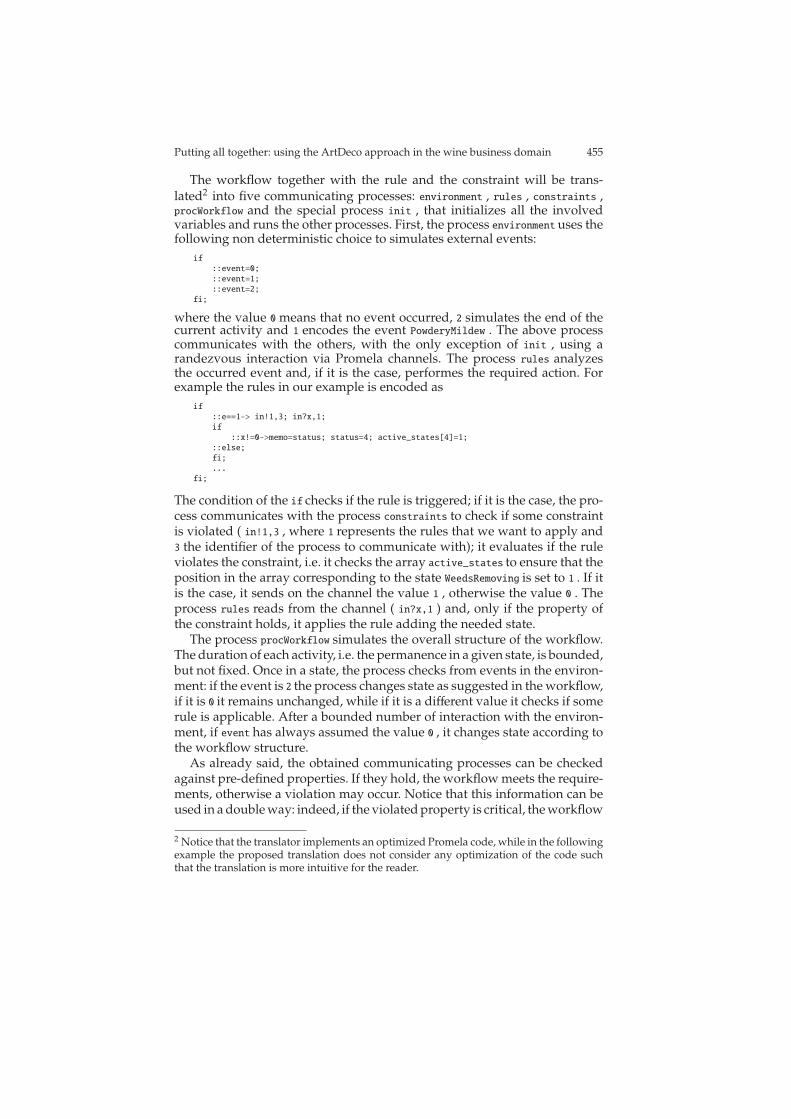
According to the global system architecture presented in Fig. 6, we nowdescribe the “Knowledge Extraction and Management” sub-system and therelationships between its components.
Fig. 12 Data and knowledge base architecture
The sub-system consists mainly of three modules: (i) an ontology-basedindexing mechanism for accessing Web documents that may be of interest forthe quality control unit (e.g., the quality-manager); (ii) a federated relationaldatabase that provides a virtual integrated-schema for various informationsources such as the operational and analytical databases of the enterpriseas well as the database extensions for managing the Web documents andthe sensors data; (c) a data warehouse materialising the result of interestingpre-computed queries for supporting precise analytical tasks ranging from
Putting all together: using the ArtDeco approach in the wine business domain 457
common sales analysis to more innovative tasks such as product-qualityassessment using the sensors data collected during the product’s life-cycleand customers taste prediction based on data collected from wine blogs andweb-sites.
3.2.1 Semantic indexer
This component can be exploited by the Quality Manager or by the Mar-keting (during wine design) to search for specific documents from a sharedrepository. Search is supported by semantic annotations that link documentswords with the concepts of a domain ontology. This way, the keywords usedduring search can be significant also when they have not a direct matchwith the words of the searched documents. Ontology navigations make itpossible to find semantically equivalent concepts and consequently to findfurther significant keywords for performing the search. This approach makesit possible to retrieve a larger set of documents from the repository.
To perform semantic search, three phases are needed: (1) text extractionfrom heterogenous documents; (2) text annotation with concepts of a domainontology; (3) semantic indexing of documents with concepts. Only at thispoint, queries can be issued. In the following, the three phases are describedwith reference to an example in the context of the wine scenario.
The Text Extractor module gathers text from several document formats(PDF, HTML pages, etc.). The extracted text, as well as the original documentfile (if any), are stored into the Document Repository. For each word of thedocuments, the engine selects the related concept of the Domain Ontology.Thus, the Conceptual Index provides an abstract view of the documents,permitting users to search for concepts. A classic TF-IDF scheme is applied, inorder to generate the documents’ concept vectors, stored into the ConceptualIndex.
The concepts-words mappings generated during the indexing proce-dure are then arranged as an index and stored into the Conceptual Index.As an example, consider the sentence ”The bottle with red label containsBarolo, a red wine”. The human expert associates words and concepts,producing ”The bottle/WINE-BOTTLE with red label/WINE-LABEL con-tains Barolo/BAROLO-WINE, a red/RED-WINE wine/WINE”, where WINE-BOTTLE, WINE-LABEL, BAROLO-WINE, RED-WINE, and WINE representconcept IDs (see chapter 9 for details).
Now, if the system has been trained to recognise concepts in the follow-ing set WINE-BOTTLE, WINE-LABEL, BAROLO-WINE, RED-WINE, WINEand the document set is composed of D1 =”Barolo is a small village wheregood wine is produced” and D2=”Barolo is a red wine”, the system extractsthe following sets of concepts C1=WINE, WINE and C2=BAROLO-WINE,RED, WINE. The TF-IDF calculates the weight wc,d associated to each con-cepts c, for each document d; thus, the following vectors are generated:

458 Authors Suppressed Due to Excessive Length
V1=[0, 0, 0, 0, WWINE,D1] and V2=[0, 0, WBAROLO−WINE,D2
, WRED−WINE,D2,
WWINE,D2].
The Query Engine, exploiting both the Conceptual Index and the DomainModel, permits to formulate concept-based queries on the document collec-tion. Searching for a given concept, the system finds every mapped word,and calculates a ranked list of documents. Keyword based queries are com-posed of a sequence of words, connected by either AND or OR boolean logicoperators. As an example of AND query, if the user issues Q=”Barolo wine”,the system indexes the text and produces the following sequence of con-cepts: VQ=[0, 0, WBAROLO−WINE,Q, 0, WWINE,Q]. Then, it compares the vectorVQ against V1 and V2, and finds the nearest document.
3.2.2 Federated database
As it is commonly done in modern information integration systems, the datastructures supporting the Knowledge Extraction and Management systemare engineered by following classic conceptual and logical design flowsconsisting of:
• Conceptual Design of the mediated global schema, also called integrationschema.
• Logical Design of the mediated global schema.• Logical Design of the mappings between the global schema and the
data-source schemas.• Conceptual Design of the data warehouse for the analysis of facts of
interest.• Logical Design of the data warehouse.
In addition to the steps above, we also need to design the necessary structuresto allow context-aware querying. This requires two additional steps in thedesign methodology, namely:
• Conceptual Design of the context-model for quality assessment.• Logical Design of the context-aware views.
The first step is the design of the mediated schema, which acts as a globalview over the enterprise’s information legacy.
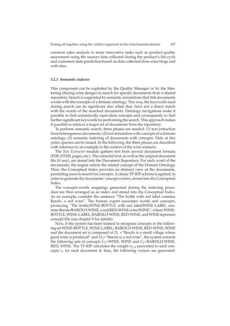
The schema models all the information related to the wine productionprocess and the structures needed to store sensors data collected for all theobjects of interests (e.g., cellars, vineyards, barrels and bottles). Moreover,we collect also data about atmospheric phenomena that interested certainareas of the vineyard, since they could have affected the quality of the wine,along with information about the returned lots of products that are usually astarting point for the quality assessment process. The relational schema thatwe adopt for the wine case-study is shown in Fig. 13.
Putting all together: using the ArtDeco approach in the wine business domain 459
WINE(appellation, category, vinification)
REF-COMP(appellation, tech−name, min %, max %)
GRAPEVINE(tech−name, name, variety)HARVEST(h− id,vineyard− id, note)
CELLAR(cl− id, material, type, vineyard-id, harvest-id)BARREL(bl− id, wood, type, cellar-id)COMPOSITION(bottle− id,barrel− id, wine %)BOTTLE(b− id, bott-date, harvest-date, price, appellation,lot-id)LOT(l− id, pkg-date, pkg-type, return-date, sale-date, cr-id, cs-id)CUSTOMER(c− id, name, address)VINEYARD(v− id, hectares, fraction, municipality, district, region, zone)ROW(r− id,vineyard− id, plant-date, tech-name, phenological-phase)
PHENOMENON(vineyard− id,phenomenon,date, type, notes, emergency-plan)
DAMAGE((vineyard− id,row− id,name,date), analysis)
SENSOR-BOARD((sb− id), coordinates, act-date, obj-id)
SENSOR(s− id, type, model, meas-unit)MEASURE-DATA(date, time,sensor− id, value)
Fig. 13 Relational Schema for the Wine Use-case
3.2.3 Creating the Data-Mart for quality assessment
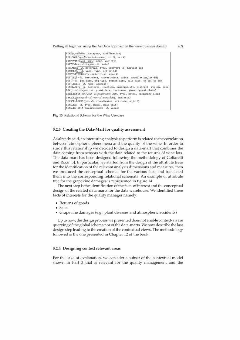
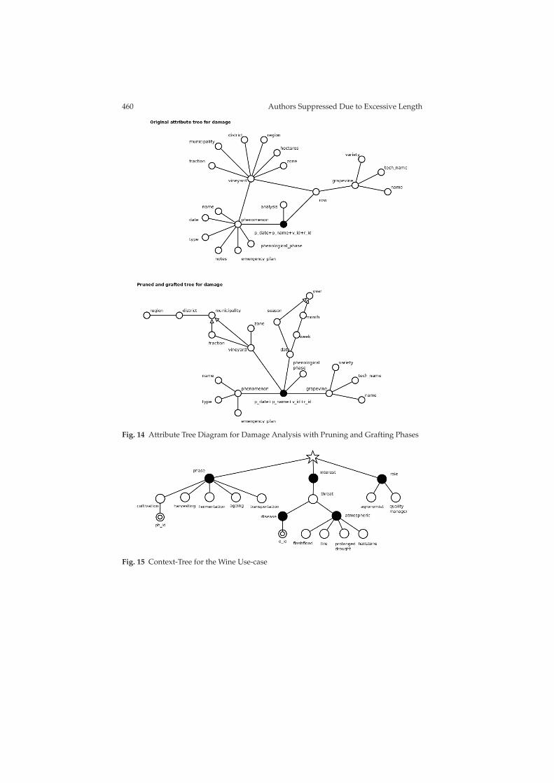
As already said, an interesting analysis to perform is related to the correlationbetween atmospheric phenomena and the quality of the wine. In order tostudy this relationship we decided to design a data-mart that combines thedata coming from sensors with the data related to the returns of wine lots.The data mart has been designed following the methodology of Golfarelliand Rizzi [5]. In particular, we started from the design of the attribute treesfor the identification of the relevant analysis dimensions and measures, thenwe produced the conceptual schemas for the various facts and translatedthem into the corresponding relational schemata. An example of attributetree for the grapevine damages is represented in figure 14.
The next step is the identification of the facts of interest and the conceptualdesign of the related data marts for the data warehouse. We identified threefacts of interests for the quality manager namely:
• Returns of goods• Sales• Grapevine damages (e.g., plant diseases and atmospheric accidents)
Up to now, the design process we presented does not enable context-awarequerying of the global schema nor of the data-marts. We now describe the lastdesign step leading to the creation of the contextual views. The methodologyfollowed is the one presented in Chapter 12 of the book.
3.2.4 Designing context relevant areas
For the sake of explanation, we consider a subset of the contextual modelshown in Part 3 that is relevant for the quality management and the
460 Authors Suppressed Due to Excessive Length
Fig. 14 Attribute Tree Diagram for Damage Analysis with Pruning and Grafting Phases
Fig. 15 Context-Tree for the Wine Use-case
Putting all together: using the ArtDeco approach in the wine business domain 461
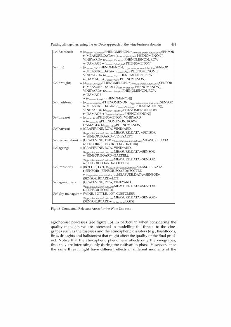
Rel(flashfood) = {σname=′ f lash f ood′PHENOMENON, πtype,value,measunit,date,timeSENSORZ(MEASURE DATAX (σname=′ f lash f ood′PHENOMENON)),VINEYARDX (σname=′ f lash f ood′PHENOMENON, ROWX(DAMAGEZ (σname=′ f lash f ood′PHENOMENON)}
Rel(fire) = {σname=′ f ire′PHENOMENON, πtype,value,measunit,date,timeSENSORZ(MEASURE DATAX (σname=′ f ire′PHENOMENON)),VINEYARDX (σname=′ f ire′PHENOMENON, ROWX(DAMAGEZ (σname=′ f ire′PHENOMENON)}
Rel(drought) = {σname=′drought′PHENOMENON, πtype,value,measunit,date,timeSENSORZ(MEASURE DATAX (σname=′drought′PHENOMENON)),VINEYARDX (σname=′drought′PHENOMENON, ROWX(DAMAGEZ (σname=′drought′PHENOMENON)}
Rel(hailstone) = {σname=′hailstone′PHENOMENON, πtype,value,measunit,date,timeSENSORZ(MEASURE DATAX (σname=′hailstone′PHENOMENON)),VINEYARDX (σname=′hailstone′PHENOMENON, ROWX(DAMAGEZ (σname=′hailstone′PHENOMENON)}
Rel(disease) = {σname=$d idPHENOMENON, VINEYARDX (σname=$d idPHENOMENON, ROWXDAMAGEZ (σname=$d idPHENOMENON)}
Rel(harvest) = {GRAPEVINE, ROW, VINEYARD,πtype,value,measunit,date,timeMEASURE DATA ZSENSORX(SENSOR BOARDZVINEYARD)}
Rel(fermentation) = {GRAPEVINE, TUB πtype,value,measunit,date,timeMEASURE DATAZSENSORX(SENSOR BOARDZTUB)}
Rel(ageing) = {GRAPEVINE, ROW, VINEYARD,πtype,value,measunit,date,timeMEASURE DATAZSENSORX(SENSOR BOARDZBARREL),πtype,value,measunit,date,timeMEASURE DATAZSENSORX(SENSOR BOARDZBOTTLE)}
Rel(transport) = {BOTTLE, LOT, πtype,value,measunit,date,timeMEASURE DATAZSENSORX(SENSOR BOARDZBOTTLEZ πtype,value,measunit,date,timeMEASURE DATAZSENSORX(SENSOR BOARDZLOT)}
Rel(agronomist) = {GRAPEVINE, ROW, VINEYARD,πtype,value,measunit,date,timeMEASURE DATAZSENSORX(SENSOR BOARD}
Rel(qlty-manager) = {WINE, BOTTLE, LOT, CUSTOMER,πtype,value,measunit,date,timeMEASURE DATAZSENSORX(SENSOR BOARDZ σc id<>nullLOT)}
Fig. 16 Contextual Relevant Areas for the Wine Use-case
agronomist processes (see figure 15). In particular, when considering thequality manager, we are interested in modelling the threats to the vine-grapes such as the diseases and the atmospheric disasters (e.g., flashfloods,fires, droughts and hailstones) that might affect the quality of the final prod-uct. Notice that the atmospheric phenomena affects only the vinegrapes,thus they are interesting only during the cultivation phase. However, sincethe same threat might have different effects in different moments of the
462 Authors Suppressed Due to Excessive Length
cultivation phase, we need a parameter to distinguish among the differentmoments of the cultivation (i.e., the phenological phases). The other phasesrepresented in the context model are interesting for the analysis of the sen-sors data, in order to identify possible problems in the production chain thatmight affect the quality of the wine.
Moreover, we are interested in modelling also the information that arerelevant for the agronomist, during the harvest phase, which include, besidesthe information related to vineyards and grapevines, the data collected bysensors placed in the vineyards. Other phases represented in the contextmodel, and in particular the cultivation and ageing phases, are interestingfor the agronomist as well; indeed she/he can analyse sensors data that areplaced in the vineyards, in order to identify possible problems related to thecultivation in different periods of year.
By leveraging on the context model, for each value of each dimension, wedefine a view over the database (or the data warehouse) that consists of all thedata that might be of interest for that value (i.e., the relevant area). Figure 16shows the definitions in Relational Algebra of the views associated to theatmospherical events and to the quality-manager and agronomist roles.
Once the all the views corresponding to the dimension values have beendefined, the methodology described in Part 3 allows us to combine themto obtain the view associated to a given context. Consider for example, thesituation of the quality manager interested in the analysis of data comingfrom sensors during the transportation phase. The associated contexts C1
and C2 will be:
C1 = < transport, *, quality-manager >C1 = < harvest, *, agronomist >
Where the symbol ’*’ means that we do not care about the value of theinterest dimension. Given the views definitions given above, the resultingview for the context C1 and C2 is shown in Figure 17. This view can beeasily implemented as an SQL view over the WineDB database and usedwhenever the quality manager is analysing the sensors data collected duringthe transportation phases.
Rel(harvest, , agronomist) = {GRAPEVINE, ROW, VINEYARD,πtype,value,measunit,date,timeMEASURE DATAZSENSORX(SENSOR BOARDZVINEYARD)}
Rel(transport, ,qlty-manager) = {BOTTLE, LOT, πtype,value,measunit,date,timeMEASURE DATAZSENSORX(SENSOR BOARDZ σc id<>nullLOT)}
Fig. 17 Contextual Views
Putting all together: using the ArtDeco approach in the wine business domain 463
3.3 Monitoring physical environments with wireless sensors
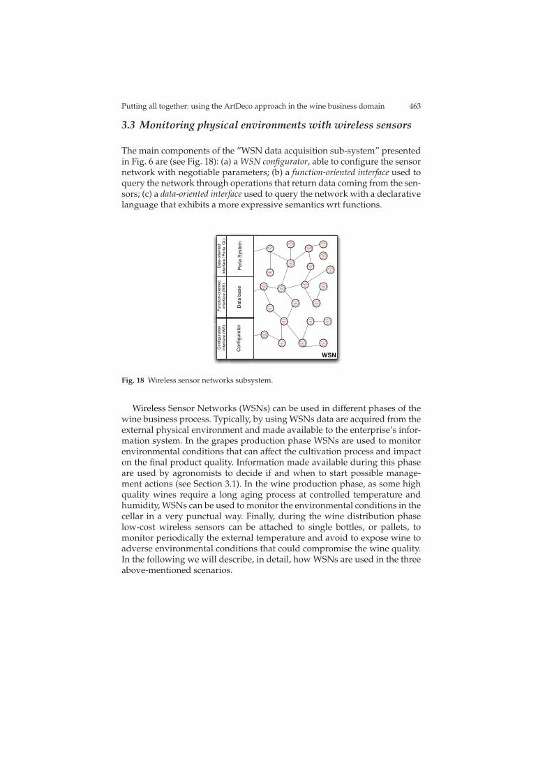
The main components of the ”WSN data acquisition sub-system” presentedin Fig. 6 are (see Fig. 18): (a) a WSN configurator, able to configure the sensornetwork with negotiable parameters; (b) a function-oriented interface used toquery the network through operations that return data coming from the sen-sors; (c) a data-oriented interface used to query the network with a declarativelanguage that exhibits a more expressive semantics wrt functions.
WSN
Pe
rla
Syste
mD
ata
ba
se
Co
nfig
ura
tor
Fu
nctio
n-o
rie
nte
d
inte
rfa
ce
(W
S)
Da
ta-o
rie
nte
d
inte
rfa
ce
(P
erla
Q
L)
Co
nfig
ura
tio
n
inte
rfa
ce
(W
S)
Fig. 18 Wireless sensor networks subsystem.
Wireless Sensor Networks (WSNs) can be used in different phases of thewine business process. Typically, by using WSNs data are acquired from theexternal physical environment and made available to the enterprise’s infor-mation system. In the grapes production phase WSNs are used to monitorenvironmental conditions that can affect the cultivation process and impacton the final product quality. Information made available during this phaseare used by agronomists to decide if and when to start possible manage-ment actions (see Section 3.1). In the wine production phase, as some highquality wines require a long aging process at controlled temperature andhumidity, WSNs can be used to monitor the environmental conditions in thecellar in a very punctual way. Finally, during the wine distribution phaselow-cost wireless sensors can be attached to single bottles, or pallets, tomonitor periodically the external temperature and avoid to expose wine toadverse environmental conditions that could compromise the wine quality.In the following we will describe, in detail, how WSNs are used in the threeabove-mentioned scenarios.
464 Authors Suppressed Due to Excessive Length
3.3.1 WSN middleware
The middleware represents the physical interface between the WSN and therest of the enterprise’s information system. To allow an efficient interactionbetween application processes and sensor nodes, two different middlewaresolutions have been developed in the project, which take alternative ap-proaches. The former solution, described in Chapter 4.3, relies on a service-oriented paradigm. The middleware layer allows an application process toestablish a service agreement with the underling WSN and hide low leveldetatil as programming interface and embedded OS. (see the module Con-figurator in Fig. 18).
For the wine application scenario, three different kinds of service havebeen considered and, correspondingly, the following three service contractshave been defined.
• Periodic Measurement contract: is used to periodically measure a certainphysical quantity (e.g., temperature);
• Event Monitoring contract: is used to monitor specific events (e.g., Tem-perature exceeding or the Battery Voltage go down a given threshold);
• Network Management contract: is used to manage and control the WSNbehaviour.
The above schemas are used for both adaptation of the behavior of thesensors to the environmental conditions and for reducing the power con-sumption of the sensors. Both are important aspects to be considered whenusing sensor networks for monitoring outdoor scenarios such as vineyards.The first goal was to implement a mechanism to automatically reconfigure aWSN. The scenario envisages a sensor that periodically acquires data relatedto the brightness level it senses, and sends such data to the base station. Wesupposed that a year is divided in two different periods, namely the sum-mer and the winter, and that during the winter the rate at which the sensorcollects and sends data can be reduced to the half of the corresponding rateduring the summer. To this end, we implemented a function that automati-cally sets the sampling rate (the rate at which the sensor collects and sendsdata) during the winter at the half of the sampling rate during the summer.Furthermore, we implemented another function, which allows to set thesampling frequency from the base station, by sending an asynchronous mes-sage. The payload of the message contains the desired value of the samplingfrequency, and the sensor has to extract that payload and appropriately setthe sampling rate.
The nesC language has been utilized for the activities on sensor networkprogramming with sensors running the TinyOS operating system. In theactivities, they worked towards the implementation of two new in-networkfunctions.
The second goal was related to the reduction of the power consumption.This is a very hot topic and a critical issue whenever it is difficult to replace
Putting all together: using the ArtDeco approach in the wine business domain 465
the batteries of the sensors. The scenario under analysis envisages a coupleof sensors sending packets to each other. In this scenario, when a sensor isnot sending or receiving packets, it has to ’go to sleep’ for a certain time byswitching off the radio (that is the most power-consuming functionality). Toimplement this behavior, we exploit the LowPowerListening functionalities.LowPowerListening interfaces allow to set the local node’s radio sleep inter-val which define the time interval in which the radio is switched off. Afterthis interval the radio is turned on for receiving check intervals to performClear Channel Assessment according to the 802.15.4 standard.
As a candidate application, we consider the temperature monitoring ina certain region of a vineyard and we study the behavior of a concreteimplementation of the middleware, tailored to TinyOS 2.x and featured by asimple QoS admission control module. For the sake of simplicity, the WSNtestbed is characterized by a network star topology, in which a node acts asa coordinator and the other ones act as end-devices. The nodes are deployedall around the monitored area and have different tasks according to theircategory:
• The Coordinator node, connected to a resource-unconstrained machine(i.e. a pc), is responsible for interfacing the WSN with the higher level ar-chitecture through the WSNGateway. The coordinator receives data com-ing from the end-devices and forwards them to the WSNGateway. Also, itreceives commands from the WSNGateway and forwards them to properend-device nodes. In the current implementation, commands concern ac-tivation and deactivation of sensors on a node, and setting/changing ofthe sampling periods.
• The End-Device node is responsible for gathering data from active sensorsand sending them to the coordinator node.
Every end-device node is a composed by:
• Crossbow MicaZ a 2.4 Ghz mote module used for enabling low-power,wireless sensor network, featuring the:
• ATMEL ATmega128, a low-power CMOS based on the AVR enhancedRISC architecture.
• Chipcon SmartRF CC2420, a single-chip 2.4 GHz IEEE 802.15.4 compli-ant RF transceiver.
• Crossbow BelosB mote platform including a suite sensor with light,temperature and humidity sensor, featuring the:
– TI MSP430, a powerful 16-bit RISC CPU.– Chipcon SmartRF CC2420, a single-chip 2.4 GHz IEEE 802.15.4 com-
pliant RF transceiver.
• Crossbow Sensor Board MDA100CB, a sensor board that provides aprecision thermistor, a light sensor/photocell and general prototypingarea.
466 Authors Suppressed Due to Excessive Length
Moreover, the TelosB platform is equipped with a Voltage sensor thatallow monitoring the battery level and using this information for estimationof battery decrease as a function of the sampling time. On every node, theTinyOS 2.0 embedded operating system runs along with the applicationprogram written in the NesC language. In particular, the Coordinator noderuns the BaseStation TinyOS application to manage data packets comingfrom the network and send command packets to the network. Every end-device runs an application program composed by several TinyOS interfaceslinked together to provide the following features:
• dynamic adjustment of sensor sampling rates.• power saving through the asynchronous low power listening (LPL) strat-
egy.• dynamic sensor activation/deactivation.
The alternative solution, described in Chapter 4.4, takes a data-orientedapproach and regards the entire WSN as a database [9]. The WSN can thusbe queried just as a traditional database. A specific middleware layer and alanguage to install queries and extract data from a WSN have been designedand implemented in the project. Specifically, the following three differenttypes of queries can be executed.
• Low Level Queries are used to access data produced by sensor nodes.Both periodic and event-triggered data extraction paradigms are sup-ported;
• High Level Queries are used to perform data manipulation operations;• Actuation Queries are used to set parameters at sensor nodes (e.g., for
modifying software variable).
Both solutions have been defined and implemented. The application devel-oper can thus select one the two above-mentioned approaches to programinteractions between applications processes and the underlying WSN.
In the following, we will assume the presence of two different types ofdevices:
• DA which embeds temperature and humidity sensors.• DB which embeds only a pressure sensor.
The sensors are configured as logical objects with the following attributes:
• LA: id, device type, zone, temp, hr• LB: id, device type, zone, bar
where id is a unique identifier for the logical object, zone is a static attributeconfigured at deploy-time and temp, hr and bar represent the sensed values.For example if we want to continuously sample the temperature and thehumidity over the entire vineyard and put the results in a stream calledMEASURE DATA. We suppose that sampling frequency is of 1 sample every300 seconds. The correspondent PERLA query will result as follows:
Putting all together: using the ArtDeco approach in the wine business domain 467
CREATE [OUTPUT] STREAM MEASURE_DATA AS
LOW:
EVERY ONE
SELECT id, temp, hr FROM LA
SAMPLING
EVERY 300 s
If we want to filter the previous stream in order to generate an alarmcondition to cope with the alarm condition about rime (where rime occurswith a condition of temperature ¡ 5C and humidity ¿ 75%. We have thefollowing query:
SELECT id FROM MEASURE_DATA
WHERE temp < 5 AND hr > 75 %
Sometimes it is not necessary to activate all the sensors at the same time.For example, if we want to monitor a group of adversities with a restrictedgroup of sensors, we might start by monitoring the common magnitudes andthen start the other sensors when certain alarm conditions are reached. If wewant to monitor the average temperature in a given zone of the vineyardand we suppose to start the sampling of pressure conditions on the samezone only if the temperature raises up to 30 Celsius, we’ll have the followingquery:
CREATE [OUTPUT] STREAM ZONE_TEMP AS
SELECT id, temp, zone
GROUP BY (zone)
HAVING AVG(Temp) > 30
WHERE zone = \$zone_id
CREATE [OUTPUT] STREAM PRESSURE AS
LOW:
EVERY ONE
SELECT bar FROM LB
PILOT JOIN ZONE_TEMP ON ZONE_TEMP.zone=LB.zone
3.3.2 WSN deployment and data communication
Data acquired by sensors are transferred, through a wireless Gateway node,to the Data Collection Server, from where they can be accessed - even re-motely - to support appropriate decisions.
As anticipated in Section 3.1, the following physical quantities need to bemonitored in a vineyard to control the grapes cultivation process: tempera-ture, leaf witness, soil moisture, wind speed and direction, and rain intensity.Therefore, sensor nodes must be equipped with appropriate sensors. Specif-ically, all sensor nodes in the network include sensors for temperature, leafwetness and soil moisture, so as to achieve a fine-grain monitoring of the cor-responding physical quantities. In addition, there are one pluviometer andone anemometer for the entire network. Technical characteristics of sensorsused in our testbed are shown in Table 1.

468 Authors Suppressed Due to Excessive Length
Fig. 19 Sensors used for vineyard monitoring.
Sensor nodes are deployed on plants in the vineyard - at a distance of10-20m - so as to form a regular grid. A single-hop or a multi-hop networkcan be used, depending on the size of the monitoring area. In both casesdata acquired by sensors are transferred, through short-range wireless com-munication, to the local Gateway that is in charge of collecting data andtransferring them to the Data Server. To this purpose, the Gateway nodeuses a long-range radio link. The Gateway is also responsible for receivingcontrol messages from the Data Server and forwarding them to all sensornodes, or a subset of them (e.g., for changing the configuration parameters).Irrespective of the network topology (i.e., single-hop or multi-hop), commu-nication must be energy efficient as sensor nodes are powered by batteriesand have a limited energy budget. Therefore, specific energy conservationtechniques must be implemented to prolong the network lifetime [1]. Solu-tions for efficient energy management in single-hop and multi-hop WSNshave been discussed in Chapters 4.1 and 4.2, respectively. The proposed ap-proaches rely on the concept of duty cycle, i.e., sensor nodes switch off theirradio when there is no message to receive or transmit. Duty cycle is a veryeffective solution for sensor nodes as they have a limited network activityand use short-range communication. However, this is not sufficient for theGateway node as (i) it manages an amount of traffic much larger than anyother node in the network, and (ii) it uses long-range radio communication totransmit data to the Data Server, which consumes a lot of energy. Therefore,the Gateway also includes an energy harvesting system, based on solar cells,to scavenge energy from the external environment. A detailed descriptionof the Gateway node and its integrated energy harvesting system is given inChapter 4.1. Many of the concepts presented above for the vineyard WSNalso apply to the cellar WSN used for monitoring the wine aging process. Inthis application scenario the relevant environmental data to be monitored aretemperature and humidity. To this end, sensors already integrated in sensornodes are used, without any need for specific external sensors. Sensor nodesare deployed strategically in some specific points of the cellar to provide afine-grain monitoring of the sensing area. As in the vineyard WSN, both asingle-hop or multi-hop topology can be used - depending on the size ofthe sensing area - and similar energy management techniques are used forenergy conservation at sensor nodes. As above, data acquired by sensors are
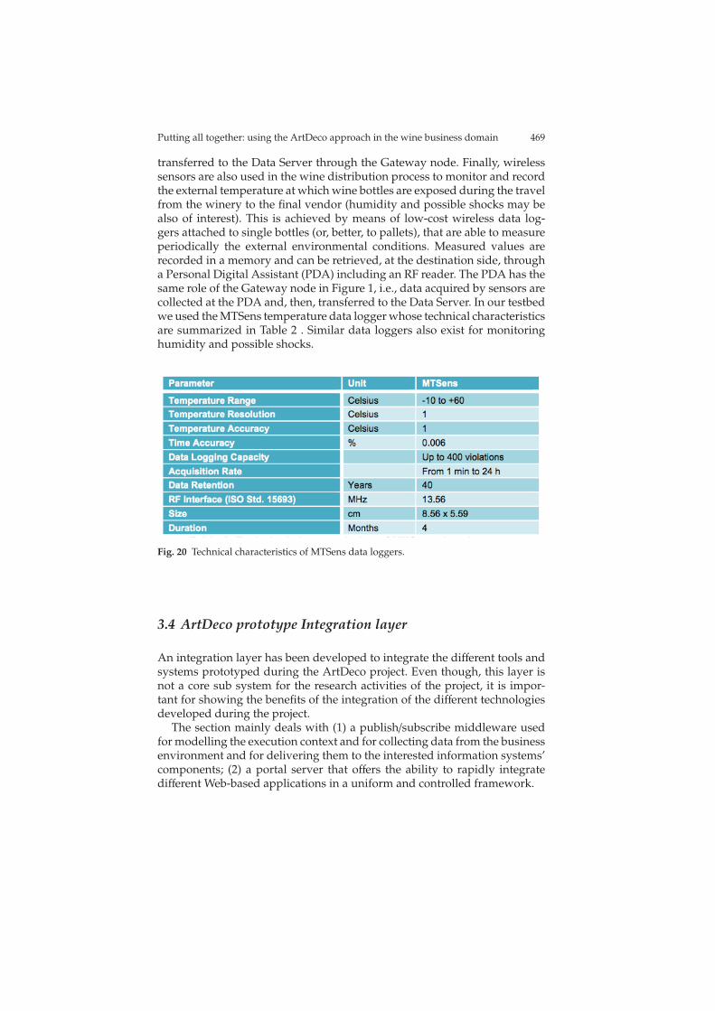
Putting all together: using the ArtDeco approach in the wine business domain 469
transferred to the Data Server through the Gateway node. Finally, wirelesssensors are also used in the wine distribution process to monitor and recordthe external temperature at which wine bottles are exposed during the travelfrom the winery to the final vendor (humidity and possible shocks may bealso of interest). This is achieved by means of low-cost wireless data log-gers attached to single bottles (or, better, to pallets), that are able to measureperiodically the external environmental conditions. Measured values arerecorded in a memory and can be retrieved, at the destination side, througha Personal Digital Assistant (PDA) including an RF reader. The PDA has thesame role of the Gateway node in Figure 1, i.e., data acquired by sensors arecollected at the PDA and, then, transferred to the Data Server. In our testbedwe used the MTSens temperature data logger whose technical characteristicsare summarized in Table 2 . Similar data loggers also exist for monitoringhumidity and possible shocks.
Fig. 20 Technical characteristics of MTSens data loggers.
3.4 ArtDeco prototype Integration layer
An integration layer has been developed to integrate the different tools andsystems prototyped during the ArtDeco project. Even though, this layer isnot a core sub system for the research activities of the project, it is impor-tant for showing the benefits of the integration of the different technologiesdeveloped during the project.
The section mainly deals with (1) a publish/subscribe middleware usedfor modelling the execution context and for collecting data from the businessenvironment and for delivering them to the interested information systems’components; (2) a portal server that offers the ability to rapidly integratedifferent Web-based applications in a uniform and controlled framework.
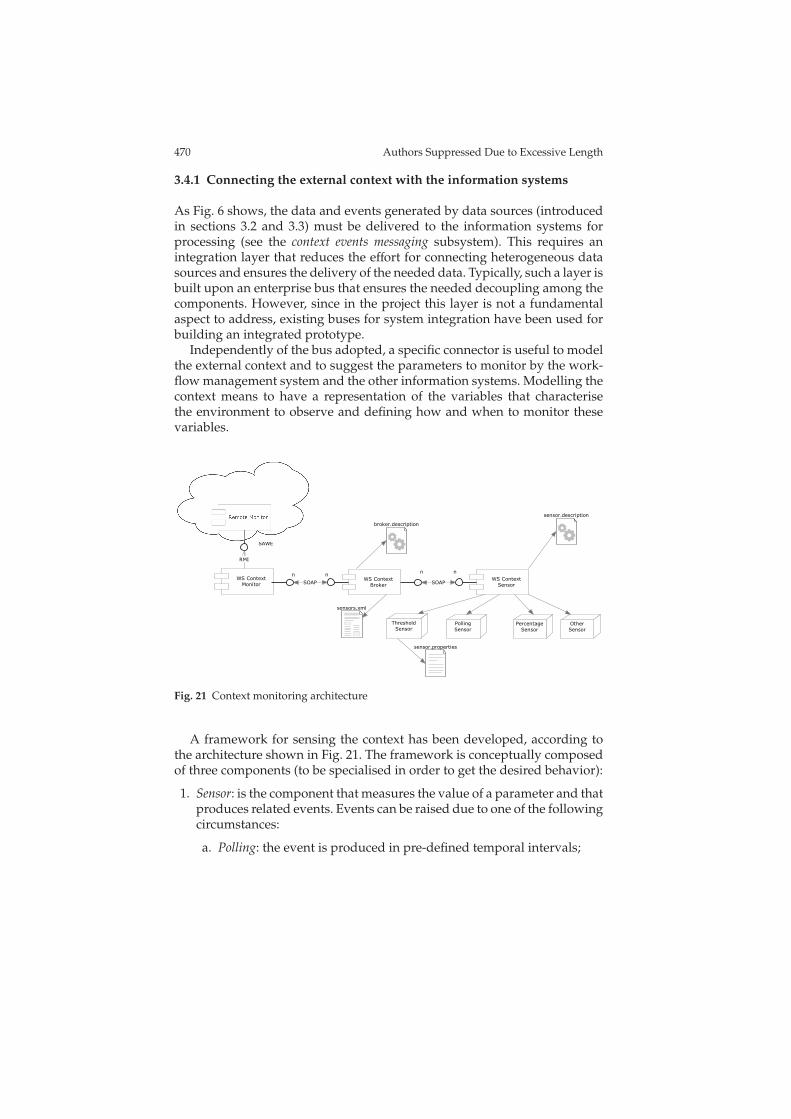
470 Authors Suppressed Due to Excessive Length
3.4.1 Connecting the external context with the information systems
As Fig. 6 shows, the data and events generated by data sources (introducedin sections 3.2 and 3.3) must be delivered to the information systems forprocessing (see the context events messaging subsystem). This requires anintegration layer that reduces the effort for connecting heterogeneous datasources and ensures the delivery of the needed data. Typically, such a layer isbuilt upon an enterprise bus that ensures the needed decoupling among thecomponents. However, since in the project this layer is not a fundamentalaspect to address, existing buses for system integration have been used forbuilding an integrated prototype.
Independently of the bus adopted, a specific connector is useful to modelthe external context and to suggest the parameters to monitor by the work-flow management system and the other information systems. Modelling thecontext means to have a representation of the variables that characterisethe environment to observe and defining how and when to monitor thesevariables.
!"#$%"&'$()%$*
+, -$(%".%
'$()%$*+, -$(%".%
/*$0"*
+, -$(%".%
,"(1$*
23*"13$45
,"(1$*6$44)(7
,"(1$*6"*8"(%97"
,"(1$*
1"(1$*:;*$;"*%)"1
1"(1$*:5"18*);%)$(
<*$0"*:5"18*);%)$(
1"(1$*1:.#4
,=+>
!'?
,@=6 ,@=6
( (( (
@%3"*
,"(1$*
Fig. 21 Context monitoring architecture
A framework for sensing the context has been developed, according tothe architecture shown in Fig. 21. The framework is conceptually composedof three components (to be specialised in order to get the desired behavior):
1. Sensor: is the component that measures the value of a parameter and thatproduces related events. Events can be raised due to one of the followingcircumstances:
a. Polling: the event is produced in pre-defined temporal intervals;
Putting all together: using the ArtDeco approach in the wine business domain 471
b. Threshold: the event is produced in case of overcoming of one deter-mined threshold;
c. Variation: the event is produced when the parameter varies of a cer-tain percentage in comparison to its preceding value;
2. Monitor: is the component that deals with the received events and notifiesthem to the upper layers;
3. Broker: is the intermediary component that receives events from sensorsand notifies them to the monitors. Its use is optional, but strongly rec-ommended, since it promotes the loose-coupling (in fact a Monitor maynot know the addresses of all the Measurers from which it is interestedto receive events) and it allows for the aggregation and the processing ofthe received events.
The interface for subscribing is the same for every component, so that itis possible for a Monitor to subscribe to a Sensor, to a Broker or to both andit is possible to define chains of Brokers before reaching a Monitor. A Brokermay subscribe more than one Sensor and a Sensor can be subscribed by morethan one Broker. The same behavior may be used also between Monitors andBrokers. As the monitoring, also sensing can be built in a ’recursive’ way.
For using the framework, it is needed to use a Broker as ’responsible’ ofevery context area. The Broker has the knowledge of all the Sensors of thatdetermined area and acts as intermediary between the Monitor and them.The Broker uses a semantic layer to get the description of an observablearea and the parameters available. The framework is specialized throughthe definition of three objects.
1. Event: the object that defines the event; it contains all the useful fieldsto the qualification of the same event (used by the monitoring rulesdescribed in section 3.1);
2. Measure: the object that represents the measure;3. EventListener: it defines the specific behavior of the monitor for the re-
ceived events.
The parameters belonging to a context are handled by the Context Broker.For each parameter it is possible to specify whether it is negotiable or not. Inthe case of negotiable parameter, the Context Broker negotiates a model fordata retrieving through the use of WS-Agreement. That agreement will thenbe used by the sensor of the parameter to take measurements and to sendevents.
The following is an example of the sensors.xml file managed by the Con-text Broker:
<sensors>
<sensor param="Humidity" area="ID1" negotiable="false">http://...</sensor>
<sensor param="Wind" area="ID1" negotiable="false">http://...</sensor>
<sensor param="Pluviometer" area="ID1" negotiable="false">http://...</sensor>
<sensor param="Temperature" area="ID1" negotiable="true">http://...</sensor>
<sensor param="LeafHumidity" area="ID1" negotiable="false">http://...</sensor>
<sensor param="Data" area="ID1" negotiable="false">http://...</sensor>
</sensors>
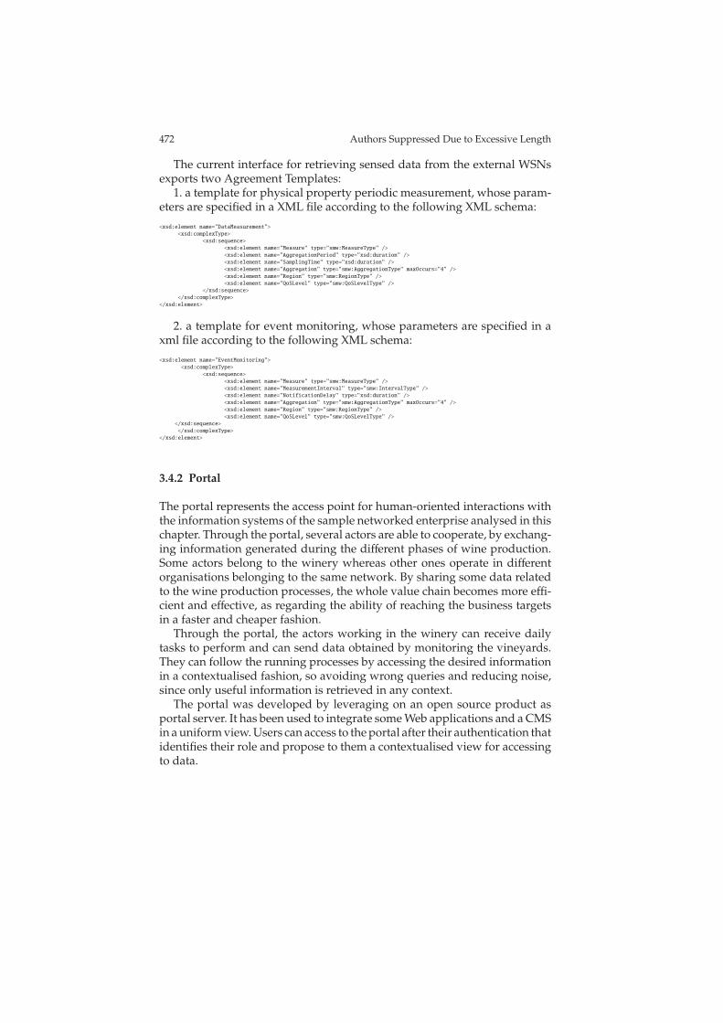
472 Authors Suppressed Due to Excessive Length
The current interface for retrieving sensed data from the external WSNsexports two Agreement Templates:
1. a template for physical property periodic measurement, whose param-eters are specified in a XML file according to the following XML schema:
<xsd:element name="DataMeasurement">
<xsd:complexType>
<xsd:sequence>
<xsd:element name="Measure" type="smw:MeasureType" />
<xsd:element name="AggregationPeriod" type="xsd:duration" />
<xsd:element name="SamplingTime" type="xsd:duration" />
<xsd:element name="Aggregation" type="smw:AggregationType" maxOccurs="4" />
<xsd:element name="Region" type="smw:RegionType" />
<xsd:element name="QoSLevel" type="smw:QoSLevelType" />
</xsd:sequence>
</xsd:complexType>
</xsd:element>
2. a template for event monitoring, whose parameters are specified in axml file according to the following XML schema:
<xsd:element name="EventMonitoring">
<xsd:complexType>
<xsd:sequence>
<xsd:element name="Measure" type="smw:MeasureType" />
<xsd:element name="MeasurementInterval" type="smw:IntervalType" />
<xsd:element name="NotificationDelay" type="xsd:duration" />
<xsd:element name="Aggregation" type="smw:AggregationType" maxOccurs="4" />
<xsd:element name="Region" type="smw:RegionType" />
<xsd:element name="QoSLevel" type="smw:QoSLevelType" />
</xsd:sequence>
</xsd:complexType>
</xsd:element>
3.4.2 Portal
The portal represents the access point for human-oriented interactions withthe information systems of the sample networked enterprise analysed in thischapter. Through the portal, several actors are able to cooperate, by exchang-ing information generated during the different phases of wine production.Some actors belong to the winery whereas other ones operate in differentorganisations belonging to the same network. By sharing some data relatedto the wine production processes, the whole value chain becomes more effi-cient and effective, as regarding the ability of reaching the business targetsin a faster and cheaper fashion.
Through the portal, the actors working in the winery can receive dailytasks to perform and can send data obtained by monitoring the vineyards.They can follow the running processes by accessing the desired informationin a contextualised fashion, so avoiding wrong queries and reducing noise,since only useful information is retrieved in any context.
The portal was developed by leveraging on an open source product asportal server. It has been used to integrate some Web applications and a CMSin a uniform view. Users can access to the portal after their authentication thatidentifies their role and propose to them a contextualised view for accessingto data.
Putting all together: using the ArtDeco approach in the wine business domain 473
4 Validation and discussion
This section reports on the experience of the Ph.D. students that attendedthe GII school organised in the context of the project.
The content of the school was designed around three groups of students,each one composed of about eight people characterized by different skills(software engineering, data base, computer networks, artificial intelligence).The two weeks of the school were structured in theoretical and practicalsessions.
During the theoretical sessions, students were provided with the mainconcepts related to the methodologies and technologies developed in theframework of the ArtDeco project, whereas during the practical sessionsstudents were involved in the experimentation with the results of the projectthough a set of exercises framed within a coherent project work. The test caseswere implemented and used by the students to experiment with the toolsdeveloped in the ArtDeco project.
In particular, each group of students worked on the same topics, solvedthe same set of exercises and prepared the same set of test cases. At the endof the school, the results of the groups were compared and the authors of thebest ones were chosen for participating in writing this chapter by providingus with some comments about their experience, that we summarize in thefollowing subsection.
4.1 Lesson learnt
Business environments involve increasingly complex and changeable pro-cesses today. To keep and improve their competitiveness, companies needinnovative methodologies to efficiently and effectively manage their Busi-ness Processes (BPs). The autonomic approach can be considered, in thisscenario, as a valuable support for the Business Process Management (BPM)lifecycle automation. BPM represents a systematic approach to incrementallydefine, analyse and innovate BPs, which can be applied to address intra- andinter-organizational issues. The BPM lifecycle starts with a modelling phaseto define user requirements describing a BP as a model. Afterwards, the BPis implemented (in the configuration phase) and executed. Finally, the BPexecution is monitored and the gathered data is analysed to identify im-provement actions to be applied to the original model. On the basis of theupdated model a new cycle can start. Operating in this manner, a BP canincreasingly evolve.
Based on organizational and business models for the development of newsystems, the autonomic methodology allows the structure and the organiza-tion of a process to be concisely and accurately represented. This guarantees
474 Authors Suppressed Due to Excessive Length
an in-depth comprehension of the process, without ambiguity, and allowsthe stakeholders to share information about its peculiarities.
Another crucial issue in the BPM life cycle is process automation i.e. thetranslation of a process model (describing a BP from the domain expert pointof view) into an executable process. To support process automation, the pro-posed methodology provides for the translation of abstract requirements,described as a process model, into an executable process through succes-sive transformations of the original model. The process model is enrichedwith implementative details and more detailed process models are generatedwhich can be easily converted into executable code. In this way the auto-nomic methodology also represents an effective support to the configurationphase in the BPM life cycle providing a workflow design approach whichproduces progressively concrete models directly executable by informationsystems.
Moreover companies working in a highly competitive and ever chang-ing environment also have to make their BPs adaptable. It often happensthat existing BPs become inadequate due to the natural changeability andcompetitiveness of the business world. To support flexibility in BPM, the au-tonomic workflows are implemented according to the ’sense-and-respond’paradigm. From this point of view an autonomic workflow provides for theexecution of the normal flow together with reactive rules able to change thebusiness processes when unexpected events occur. Using this approach BPsexecution is tailored according to different context factors and is able to fulfillthe critical issue of process adaptability in an automated and easy way .
The autonomic approach also includes techniques for process monitor-ing generating a set of data (e.g. event logs) which can be analysed to re-design the original model and improve it. For this purpose process miningtechniques could be a valuable instrument to be used within the proposedmethodology. In this context, over the last decade a variety of techniquesand algorithms have been proposed for mining process models from eventlogs, showing that information contained in the logs can be used to formal-ize or improve process models. Proposed methods have shown that eventlogs can be used to construct from scratch models underlying an automatedprocess (i.e. process discovery), or to identify discrepancies between eventlogs generated by an automated process in place and a predefined processmodel representing its formal definition (i.e. conformance testing). Both ofthese approaches to process mining can effectively meet the evolutionarynature of the ’sense-and-respond’ paradigm.
5 Conclusion
This chapter presented an approach for programming the information sys-tems of a value chain though the help of a middleware substrate designed
Putting all together: using the ArtDeco approach in the wine business domain 475
and developed in the framework of the ArtDeco project. The approach hasbeen experimented in the context of wine production and distribution, start-ing from process information gathered from domain experts. It impacts onmodelling and programming aspects (such as service description, processmodelling, workflow, data bases) and information systems used to run thewhole processes (such as WfMS, DBMS, WSN, etc).
Standard business process management languages have been extendedin order to program two orthogonal and concurrent dimensions: normalcontrol flow and context events handling. This involves the need for using anovel approach for programming the workflows that implement the businessprocesses in order to obtain an autonomic behavior at run-time. To thisend, reactive actions are driven by context events that are observed by aspecific workflow management system, extended with a context handlerthat gathers these events from heterogenous sources, such as sensors usedduring cultivation and wine production, or QoS estimates that suggest touse a supplier instead of another one.
Workflow data or queries produced by domain experts (agronomists,oenologists, etc.) are retrieved from data bases by using a context-awareapproach that reduces the amount of information that is not particularlyuseful for specific application contexts. Real-time data are collected by wire-less sensors disseminated in the business environment and programmedfollowing autonomic principles in order to improve the capacity of WSNs tosurvive as long as possible. Moreover, data mining techniques and semanticsearch have been shown as promising techniques to obtain useful informa-tion to take proper decisions in different phases of the whole process of wineproduction and distribution.
A significant part of the chapter has been devoted to the integrationproblems among the different components of the whole architecture. Themiddleware proposed in this chapter represents a conceptual framework forthe integration. However, it could be significantly enhanced in the future byproviding it with some additional non-functional features, such as: security,privacy, transactions management, performance, and scalability.
6 Acknowledgements
We thank Gaetano Anastasi, Andrea Cameli, Romolo Camplani, AngeloFurno, Ilaria Giannetti, Eugenio Marotti, Marina Polese, Emilio Sellitto, andQuirino Zagarese for their valuable contribution in developing some addi-tional components that helped the integration of the tools developed in theArtDeco Project.
476 Authors Suppressed Due to Excessive Length
References
1. Giuseppe Anastasi, Marco Conti, Mario Di Francesco, and Andrea Passarella. Energyconservation in wireless sensor networks: A survey. Ad Hoc Networks, 7(3):537–568,2009.
2. A. Cimatti, E. Clarke, E. Giunchiglia, F. Giunchiglia, M. Pistore, M. Roveri, R. Sebas-tiani, and A. Tacchella. NuSMV Version 2: An OpenSource Tool for Symbolic ModelChecking. In Proc. International Conference on Computer-Aided Verification (CAV 2002),volume 2404 of LNCS, Copenhagen, Denmark, July 2002. Springer.
3. Peled D., Pelliccione P., and Spoletini P. Model checking. In Wiley Encyclopedia ofComputer Science and Engineering. John Wiley & Sons, Inc., 2008.
4. Carlo Ghezzi. The challenges of open-world software. In WOSP, pages 90–, 2007.5. Matteo Golfarelli and Stefano Rizzi. Data Warehouse Design: Modern Principles and
Methodologies. McGraw-Hill, Inc., New York, NY, USA, 2009.6. Gerard Holzmann. Spin model checker, the: primer and reference manual. Addison-Wesley
Professional, 2003.7. Markus C. Huebscher and Julie A. McCann. A survey of autonomic computing—
degrees, models, and applications. ACM Comput. Surv., 40(3):1–28, 2008.8. Marina Polese, Giancarlo Tretola, and Eugenio Zimeo. Self-adaptive management of
web processes. In WSE 2010, pages 423–428, 2010.9. Fabio A. Schreiber, Romolo Camplani, Marco Fortunato, Marco Marelli, and Filippo
Pacifici. Perla: A data language for pervasive systems. Pervasive Computing and Com-munications, IEEE International Conference on, 0:282–287, 2008.