pv commissioning tips and best practicesprocedures. commissioning technicians face many of the same...
TRANSCRIPT

18 S O L A R PR O | March/April 2018
When done correctly, PV system-commissioning activi-ties ensure customer satisfaction, project safety and lon-gevity, while adding very little in terms of time and cost. Commissioning agents can prove that a system is working as promised, set performance baselines and verify that it
is properly documented. In return, this modest investment greatly facilitates future operations and maintenance activities.
Here we provide an overview of key precommissioning activities based on our experiences as a certified commissioning agent. We then share some post-construction commissioning tips to help you avoid common issues. These con-cepts and procedures will leave you better prepared, regardless of whether your projects are subject to in-house acceptance and sign-off tests or independent inspections by third-party commissioning agents.
What Is Commissioning? Many incentive programs, certification entities and installation manuals use the term commissioning generically to describe a set of start-up or closeout pro-cedures. In this informal context, a system installer might verify field connec-tions and ac and dc voltage levels before “commissioning” an inverter. Qualified persons adhere to similar start-up procedures before energizing any electrical component. While these steps are essential for electrical safety, they do not guarantee system performance or verify as-built conditions.
Whether you measure your project size
in kilowatts or megawatts, understanding
the key concepts and processes for
commissioning PV systems increases your
bottom line and your clients’ satisfaction.
By Nate Goodell, David Tedeyan and Gordon Woodcock
Co
urt
esy
Ta
ite
m E
ng
ine
eri
ng
PV Commissioning Tips and Best Practices
solarprofessional.com | S O L A R PR O 19
PV Commissioning Tips and Best Practices
20 S O L A R PR O | March/April 2018
PV Commissioning
In this article, we define commissioning more for-mally as a standardized and unbiased process that not only guarantees the safe operation of a PV system, but also confirms, via independent verification activities, that its documentation is correct and that it is perform-ing as expected. Commissioning agents use a variety of testing and inspection techniques to proactively iden-tify and address issues that affect plant production, operations, maintenance or safety. These formal com-missioning activities not only promote compliance with codes and engineered plans, but also help ensure that PV systems will meet energy production estimates.
In some cases, solar installation companies imple-ment common commissioning tests as part of an in-house safety or quality control program. While this is an admirable best practice, an internal company review is not necessarily unbiased from the perspec-tive of the system owner. This is why contract terms for some projects specify that project deliverables must include a third-party commissioning report. Every project pursuing LEED certification is subject to independent commissioning and verification require-ments. Many financial backers of large PV systems require independent third-party commissioning to validate their investment.
The commissioning agents responsible for gen-erating this third-party report represent the system owner rather than the installer. These agents build on the installer’s start-up procedures by performing spot checks and specialized operational tests, evaluating build quality as well as system efficiency and function-ality. They document all their findings and recommen-dations and report these directly to the system owner.
PRECONSTRUCTIONThe commissioning process begins during project planning, before construction has even started. Based on the proj-ect design documents, you want to prepare or customize a construction inspection checklist, analyze job hazards and develop a commissioning plan that reflects test priorities. All of these activities presume that you already have access to some basic yet flexible data forms and templates, as well as a library documenting common test procedures. These organizational resources are an important and often over-looked aspect of successful commissioning. To optimize workflow on-site and back in the office, companies need to have a process in place for identifying and recording abnor-malities that is accurate and easy for others to follow, which requires some advanced planning.
Prepare checklists. Commissioning agents use construc-tion inspection checklists to identify common defects and Code issues, to initiate and track the status of repairs, to
meet compliance requirements, and to ensure and docu-ment that a project is ready for functional testing.
It helps to have the end user in mind when you prepare checklists. Try to organize them logically based on the work-flow in the field. Strive to capture all relevant information. However, avoid making checklists and test forms so com-plicated that technicians spend more time filling out docu-ments than inspecting and testing the system. Reserve room for personnel to make notes in the field. The goal is to create practical and usable documents.
Weigh the benefits of using digital versus paper forms. On the one hand, digital files and data are easy to share; on the other, printed checklists never run out of batteries. A paper checklist that gets left out in a rainstorm is also less expensive to replace than a tablet or laptop. Often the best solution to field documentation is a hybrid approach. Take a set of hard-copy forms into the field and enter data by hand. At the conclusion of each component C O N T I N U E D O N PA G E 2 2
Sh
aw
n S
ch
rein
er
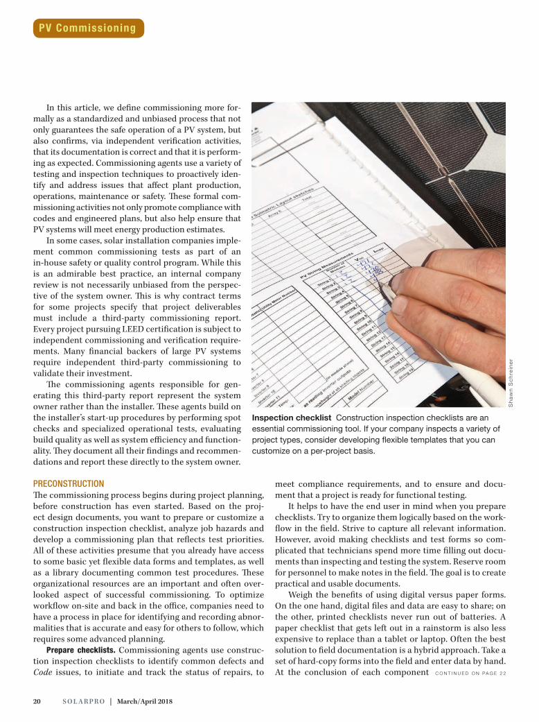
Inspection checklist Construction inspection checklists are an essential commissioning tool. If your company inspects a variety of project types, consider developing flexible templates that you can customize on a per-project basis.

22 S O L A R PR O | March/April 2018
test, photograph the completed forms so that you have a digital backup. If you use your cell phone as a camera, you can directly convert each page to a PDF with a scanner app.
A construction inspection checklist may include any of the following issues: unsupported or improperly bonded conduit; reversed conductor polarities; open homeruns; incorrectly torqued module clamps, attachments and termi-nals; improperly seated or terminated conductors; unsealed conduit or enclosure penetrations; grounding deficiencies; missing labels or system information; and discrepancies between the engineering drawings and the as-built condi-tions. Consider sharing these checklists with the project manager or site supervisor. The better they understand your pass-fail criteria, the fewer issues you should find.
Analyze hazards. Like any other employer, commissioning service providers need to systematically assess and address job hazards and develop clearly defined and documented safety procedures. Commissioning technicians face many of the same job hazards as installers, and some commissioning activ-ities may even carry a greater degree of risk. To perform opera-tional tests, for example, technicians must have the PV system up and running, which exposes them to lethal shock and arc-flash hazards. Commissioning tests intentionally simulate all
possible operating conditions. To test safety devices, techni-cians must even simulate faults and failure modes that could result in unintended consequences or equipment damage.
To comply with OSHA requirements, companies need to not only document safe working practices, but also train and supervise workers to ensure that they follow these practices. When developing a safety plan, consider every testing pro-cedure with an eye toward unwanted results. By consider-ing these hazards in advance, you can ensure that workers in the field have access to the appropriate personal protective equipment (PPE) and training.
While a comprehensive discussion of safe work prac-tices is beyond the scope of this article, commissioning personnel need to keep a few safety issues at the forefront of their minds:
P Identify all sources of power before opening any panel or enclosure.P Always utilize lockout and tagout procedures to prevent others from accidentally energizing components that you are testing.P Never assume that no voltage or current is present in a conductor unless you test it yourself, even if you just opened a disconnect.
PV Commissioning
www.solmetric.com
Expert tools.Beeer solar.
Highest accuracy and throughputLargest display with best array troubleshooong featuresDatabase of 50,000 PV modulesMeasures up to 1500V at 30A3000 wireless sensor range
...all day long in the heat of the desert. Doesn’t sound fun, but if
you’re up for it, so is the
Solmetric PV Analyzer New!
1500 Volt 30 Amp I-V Curves
solarprofessional.com | S O L A R PR O 23
To work safely, every commissioning technician needs at a minimum to have a digital multimeter with an amp clamp that can read both ac and dc current, electrically insulated
screwdrivers and gloves, and safety glasses or a face shield. These PPE requirements get more stringent as operating voltages and arc-flash hazards increase.
Develop a test plan. Visual inspections as well as performance and operational tests are an important part of the com-missioning process. The extent of these tests will depend on the size and scope of the project. As project scale increases, it becomes impractical to visually inspect or physically test every system subcompo-nent. So what and how many components
will you inspect or test?When developing a functional test plan, you need to bal-
ance testing costs against the potential financial benefits
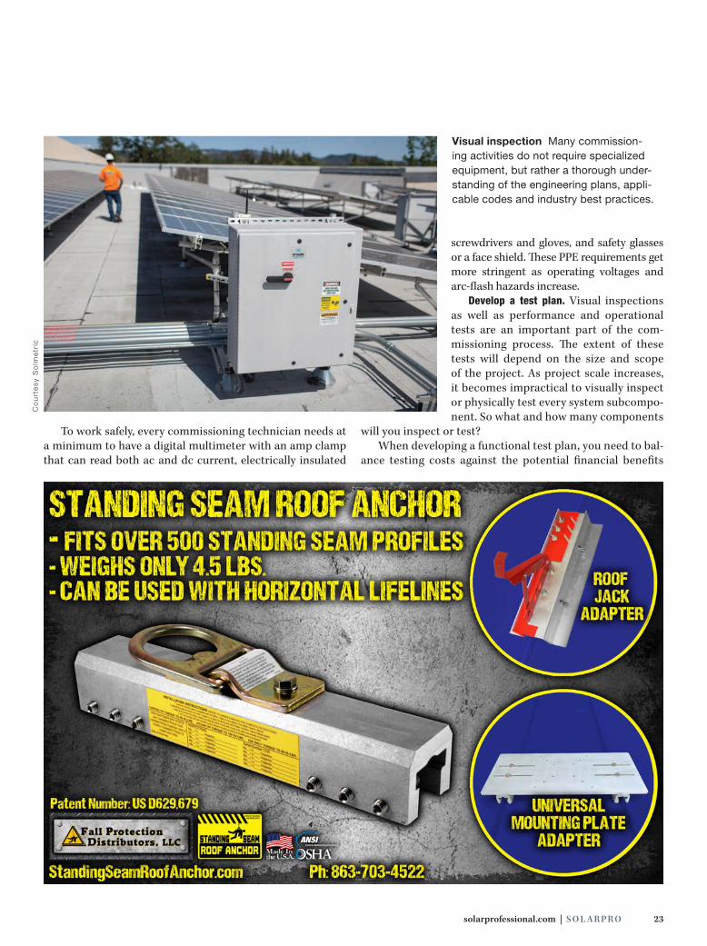
Visual inspection Many commission-ing activities do not require specialized equipment, but rather a thorough under-standing of the engineering plans, appli-cable codes and industry best practices.
Co
urt
esy
So
lme
tric

24 S O L A R PR O | March/April 2018
associated with avoided prob-lems. Many installers under-stand this balance intuitively. On the one hand, it is a function of risk and probability: What are the worst-case consequences of a component failure and how common is that failure? On the other, it is a function of expedi-ence: How easily or quickly can you run the test?
A good commissioning test plan produces maximum effect with minimum effort. Large sys-tems often necessitate sampling, in which agents test a represen-tative set of units (source circuits, combiner boxes, fuses, discon-nects and so forth) rather than all units. If multiple units within a randomly selected sample fail in the same way, you may have identified a recurring problem. In this case, you should expand the sample size. When examining these additional units, it is not necessary to run the whole battery of tests—just check for signs of a systemic issue.
POST-CONSTRUCTION By the time the project is ready for testing, you should have confirmed the commissioning test deliverables, completed installation checklists and prepared the test plan. Except in cases of recommissioning or retro commissioning, most PV system commissioning activities take place after installation is complete but prior to project closeout. In this scenario, the commissioning team is responsible for ensuring that the fielded project meets the owner’s requirements before the owner takes control.
In an earlier SolarPro article (see “Commissioning like a Pro” for more details), Blake Gleason describes the basic ele-ments of a PV system commissioning as follows:
P Verify that the installation is complete.P Verify that the installation is safe.P Verify that the installation is aesthetically acceptable.P Verify that the installation is robust and permanent.P Document as-built conditions.P Verify system performance and proper operation.P Complete required acceptance documentation.
Since Gleason elaborates on these steps, we will not spe-cifically consider each task here. Instead, we will share some
tips for successful commissioning, recommend how and when to perform critical tests, and discuss some specialized tools that commissioning agents use. Larger commercial and industrial-size systems, for example, require additional assur-ance beyond using checklists and testing voltage and current, which is where you will need more-advanced tools such as infrared (IR) cameras and I-V curve tracers.
Allocate resources wisely. When implementing the test plan, consider how you will allocate resources and look for opportunities to streamline the workflow to improve oper-ational efficiencies. Some tests are a one-person job, mean-ing that multiple people can perform these tasks at various locations in the system. Other tests are better suited to a tag-team approach, meaning they are most efficient when two or more people work together. Some tests, for example, require that technicians take readings at multi-ple locations simultaneously. In this scenario, it is best to designate one person as the lead documenter. Both tech-nicians can still take notes, but one person is specifically responsible for ensuring that all tests are completed and documented properly.
All else being equal, we recommend a workflow that starts with independent testing activities designed to identify the most obvious potential issues and then transitions to simul-taneous testing activities after team members establish a rhythm. Testing location is another consideration. Teams can lose a lot of time when they have to travel from a rooftop array down to a basement panelboard and back to the roof again.
Commissioning like a Pro
Looking for more information about commissioning activities and tools? We got you covered. For a deep dive into a variety of commissioning-related topics,
check out these articles from the SolarPro archives:
“PV System Commissioning” by Blake Gleason, October/November 2009
“Implementing a Successful Safety Program” by Karl Riedlinger, October/ November 2011
“Data Acquisition System Installation and Commissioning” by Adam Burstein and Josh Haney, April/May 2013
“Commissioning and O&M Tools” by Brian Mehalic and David Brearley, February/March 2014
“Calculating DC Arc-Flash Hazards in PV Systems” by Finley Shapiro and Brian Radibratovic, February/March 2014
“Winter Commissioning” by Michael Vance, April/May 2014
“Interpreting I-V Curve Deviations” by Paul Hernday, August/September 2014
PV Commissioning
solarprofessional.com | S O L A R PR O 25
Look for opportunities to minimize downtime by optimizing test activities around specific locations.
Know your targets. To avoid unnecessary callback visits, commissioning technicians need to verify that performance test data are within expected ranges. If the measured data do not make sense based on the anticipated results, it is impor-tant to determine whether something went wrong during the test process or whether something is wrong with the system. It is much easier to determine the root cause of an unexpected measurement in the field than back in the office.
When gathering performance test data in the field, make sure that you are documenting all of the requi-site information. If you find outliers or suspect values in the data, verify that the measurement is representative of the system and not a problem with the testing tools or methods. If an I-V curve looks strange, run another trace. If string voltage measurements do not make sense, make sure that the multimeter is not accidentally set to measure ac voltage.
In most cases, a quick investigation will turn up the cause of an erroneous or out-of-range measurement. If the problem is indeed an installation error, do your best to identify the nature of the problem in the commissioning notes. For example, you can add a lot of value to a commis-sioning report by noting that someone misidentified and incorrectly terminated a pair of conductors rather than simply reporting that you did not measure any voltage on strings 1 and 2.
Verify performance. The simplest performance verifi-cation tests start with the nameplate power rating of the system and calculate the effects of real-world irradiance and temperature measurements, as well as the estimated system-level efficiency. The aforementioned Gleason article outlines a five-step performance verification pro-cess that calculates expected power (PE) based on the fol-lowing equation:
PE = PSTC × KI × KT × KS
where PSTC is the nameplate rating of the array under standard test conditions, KI is the irradiance factor, KT is the module cell temperature factor and KS is a system derating factor.
It is not difficult to calculate the irradiance, temperature and system derate factors. To find KI, simply divide the mea-sured irradiance by the irradiance at STC (1,000 W/m2). To estimate KS, multiply system-level efficiencies together to account for power tolerance, soiling losses, age of system, inverter efficiency, and ac and dc wiring losses. The calcula-tion for KT is slightly more involved:
KT = 1 + (CT × (TC − TSTC))
Solar hot water defi ned
Engineering & manufacturing excellence since 1924
Accelera® 220 E58-gal. heat pump water heater
Accelera® 300 E80-gal. heat pump water heater
Accelera® Heat Pump Water Heater plus solar electric
800.582.8423 www.StiebelEltron.us800.582.8423 www.StiebelEltron.us
1
SOLkit 22 collectors, 80-gal. tank, plus additional componentsSOLkits come as packages of 1, 2, or 3 collectors
SOLkit Solar Thermal2

26 S O L A R PR O | March/April 2018
where CT is the module temperature coefficient, TC is the measured cell temperature and TSTC is the cell temperature under STC conditions (25°C).
The SunSpec Alliance’s best practices guide, “Com- missioning for PV Performance” (see Resources), details an initial commissioning-capacity test method, known as the power temperature coefficient model, similar to Gleason’s method. To evaluate inverter- or system-level performance in this fashion, technicians require accurate plane-of-array and module temperature measurements. Teamwork is helpful and sometimes required to capture these measurements simulta-neously with a power-output reading.
While these types of instantaneous performance tests are relatively straightforward to execute and reasonably accurate, the process does require concentration and
attention to detail. Rather than running numbers while taking measurements on the roof, have a partner sit down with a pencil and calcula-tor. If you use a spreadsheet to automate the process, technicians simply have to enter field measurements instead of performing calcu-lations manually.
Measure voltage. PV sys-tem commissioning is not necessarily a one-size-fits-all endeavor. When commiss- ioning a residential proj-ect with a multi-MPPT string inverter, you may be able to verify proper sys-tem operation—or at least rule out major issues— simply by scrolling through the inverter’s display screen. What are the Vmp values for each string? Do these values make sense based on the ambient conditions and the number of modules per source circuit? If inverter-output power also checks out, this quick-and-dirty per-formance analysis may be adequate as a system execu-tion test within the context of LEED commissioning and verification activities.
A more common and reliable commissioning practice is to independently mea-sure the Voc of each string. By isolating each string, you can tell whether a source circuit has the correct polarity and the proper number of modules in series. With con-sistent test conditions, a spreadsheet and an accurate multimeter, you can even identify module-level issues such as a failed bypass diode. When checking voltage in an inverter with multiple strings on a common bus, it is important to isolate each source circuit. In a larger inverter, you can usually open and close fuseholders under no-load conditions to take these measurements. Where two or three strings are paralleled without series fusing, as is often the case on multi-MPPT string invert-ers, you may need a tool to isolate individual source- circuit conductors.
Performance verification In addition to collecting performance verification data, com-missioning agents should verify that the measured results make sense based on predicted values. Spreadsheets are a good way to expedite this process and eliminate the need for avoidable callbacks.
Sh
aw
n S
ch
rein
er
PV Commissioning

solarprofessional.com | S O L A R PR O 27
When isolating source circuits in inverters or combiner boxes, it is important to use a dc clamp meter to check for current before opening any fuseholders or lifting any wires. If a voltage mismatch exists between strings paralleled at a
common busbar or MPPT channel—perhaps due to an installation error or equipment issues—then the higher-voltage strings can dump current into the lower-voltage string even if the dc disconnect is turned off. While the 15 A or 20 A string fusing prevents mod-ule damage, opening a circuit with current flowing in it can pull an arc capable of dam-aging equipment or starting a fire.
Check for ground faults. To check for ground faults while taking Voc measurements, simply mea-sure the voltage to ground from both the PV positive lead and the PV negative lead. Unless one of the poles of the array is intentionally connected to ground, the expected voltage
Check for current first Whenever PV source circuits are paralleled on a common bus—like the four-circuit groupings shown here—technicians need to use a dc clamp meter to test for current before opening fuseholders to take voltage measurements. Opening a circuit with current flowing in it can pull an arc capable of damaging equip-ment or starting a fire.
Co
urt
esy
Ta
ite
m E
ng
ine
eri
ng
222 North Union Street • Bryan, Ohio 43506Ph: 800-722-2679 • Fx: 800-237-7269
© 2018 Allied Moulded Products, Inc. w w w . a l l i e d m o u l d e d . c o mw w w . a l l i e d m o u l d e d . c o mw w w . a l l i e d m o u l d e d . c o mw w w . a l l i e d m o u l d e d . c o mw w w . a l l i e d m o u l d e d . c o m
222 North Union Street • Bryan, Ohio 43506
• Fiberglass Reinforced Polyester (FRP) or Polycarbonate material
• Lightweight
• Non-corrosive
• Non-conductive
• UV resistant
• Custom modifi cations
• Premium accessories
• 3D model library for easy download
NEMA 4X Vent Kit
12" x 12" AM & AM-RSeries
(FRP) or Polycarbonate material
NEMA 4X Vent Kit
ULTRAPLUG® Hole Plugs
NEMA 4X/IP66 Nonmetallic Enclosures for your Toughest Applications
Scan to learn more aboutAllied Moulded and the latest in
nonmetallic enclosures & accessories.
Or connect with us online!
HMI Cover Kits& Prop ArmNEW! 8" x 8" HMI sizes
28 S O L A R PR O | March/April 2018
reading is 0 Vdc, so it is easy to tell if a string has a ground fault.
The exception occurs where PV systems are deployed with rapid-shutdown boxes. This practice is most common in string inverter systems subject to the array-level rapid-shutdown requirements that first appeared in NEC 2014. Because the rapid-shutdown box will skew ground-fault measurements, you need to lift the strings from the box to accurately measure voltage to ground. Fortunately, it is seldom necessary to test individual strings for ground faults in this scenario, as the inverter itself is equipped with advanced ground-fault detection technology.
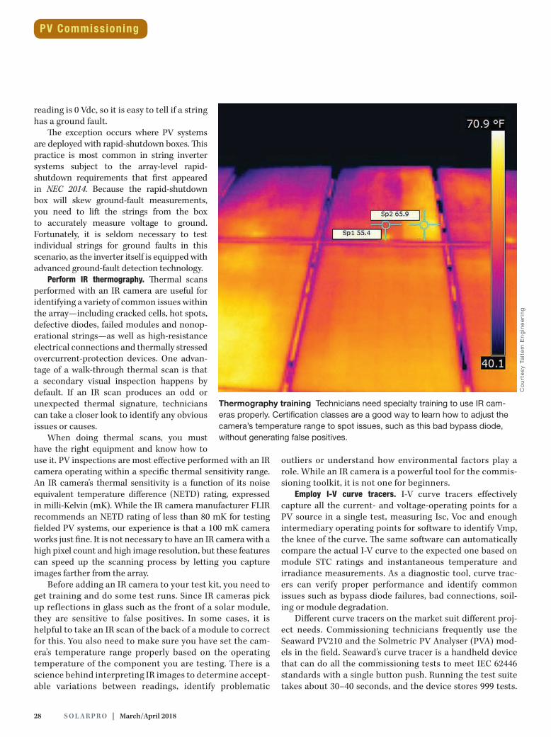
Perform IR thermography. Thermal scans performed with an IR camera are useful for identifying a variety of common issues within the array—including cracked cells, hot spots, defective diodes, failed modules and nonop-erational strings—as well as high-resistance electrical connections and thermally stressed overcurrent-protection devices. One advan-tage of a walk-through thermal scan is that a secondary visual inspection happens by default. If an IR scan produces an odd or unexpected thermal signature, technicians can take a closer look to identify any obvious issues or causes.
When doing thermal scans, you must have the right equipment and know how to use it. PV inspections are most effective performed with an IR camera operating within a specific thermal sensitivity range. An IR camera’s thermal sensitivity is a function of its noise equivalent temperature difference (NETD) rating, expressed in milli-Kelvin (mK). While the IR camera manufacturer FLIR recommends an NETD rating of less than 80 mK for testing fielded PV systems, our experience is that a 100 mK camera works just fine. It is not necessary to have an IR camera with a high pixel count and high image resolution, but these features can speed up the scanning process by letting you capture images farther from the array.
Before adding an IR camera to your test kit, you need to get training and do some test runs. Since IR cameras pick up reflections in glass such as the front of a solar module, they are sensitive to false positives. In some cases, it is helpful to take an IR scan of the back of a module to correct for this. You also need to make sure you have set the cam-era’s temperature range properly based on the operating temperature of the component you are testing. There is a science behind interpreting IR images to determine accept-able variations between readings, identify problematic
outliers or understand how environmental factors play a role. While an IR camera is a powerful tool for the commis-sioning toolkit, it is not one for beginners.
Employ I-V curve tracers. I-V curve tracers effectively capture all the current- and voltage-operating points for a PV source in a single test, measuring Isc, Voc and enough intermediary operating points for software to identify Vmp, the knee of the curve. The same software can automatically compare the actual I-V curve to the expected one based on module STC ratings and instantaneous temperature and irradiance measurements. As a diagnostic tool, curve trac-ers can verify proper performance and identify common issues such as bypass diode failures, bad connections, soil-ing or module degradation.
Different curve tracers on the market suit different proj-ect needs. Commissioning technicians frequently use the Seaward PV210 and the Solmetric PV Analyser (PVA) mod-els in the field. Seaward’s curve tracer is a handheld device that can do all the commissioning tests to meet IEC 62446 standards with a single button push. Running the test suite takes about 30–40 seconds, and the device stores 999 tests.
Thermography training Technicians need specialty training to use IR cam-eras properly. Certification classes are a good way to learn how to adjust the camera’s temperature range to spot issues, such as this bad bypass diode, without generating false positives.
Co
urt
esy
Ta
ite
m E
ng
ine
eri
ng
PV Commissioning
solarprofessional.com | S O L A R PR O 29
While the display screen provides only basic information, the accompanying Android app can show the full trace. The small form factor of the Seaward PV210 is very useful for running tests on a pitched rooftop, as is often the case in residential or small commercial applications.
In comparison, the Solmetric PVA requires a laptop to run tests. Depending on the situation, this can be advanta-geous or not. On the one hand, a laptop is one more thing to set up and manage on a rooftop. To capture an insulation resistance measurement as specified in the IEC 62446 stan-dard, technicians need yet another tool. On the other, the Solmetric PVA software can create an inverter tree and save each curve trace to the proper location in real time. On sys-tems over 500 kW, this greatly speeds documentation since you do not have to manually identify every string later. The Solmetric PVA can also do a curve trace in about 3 seconds and display it on the computer screen, allowing the user to immediately evaluate the curve. When you are working on systems with hundreds or thousands of strings, this can save hours or even days on-site.
Depending on project location and time of year, weather conditions may not be ideal to use curve tracers for for-mal performance verification activities. Consistent high- irradiance conditions are required to capture accurate data. For example, Solmetric recommends a minimum irradiance of 600 W/m2 and Seaward recommends at least 700 W/m2. In winter, there are few opportunities to meet these crite-ria in many parts of the country. Temperature can also be a consideration, as the Seaward curve tracer will not operate properly if the module temperature or ambient temperature drop below freezing.
When you are dealing with marginal weather conditions, it is important to consider your test goals. Some commissioning contracts specify that you conduct formal performance verifi-cation tests under optimal test conditions, so you may have to wait until the weather improves before capturing curve traces and IR images of the array. If requirements are less stringent, you can identify many of the most significant performance issues under suboptimal conditions. Just bear in mind that some issues will not show up without enough current flowing through the modules. In addition, the accuracy of your results suffers under suboptimal test conditions, meaning these data are not as useful for performance verification purposes.
Protect your data. When relying on electronic testing tools, it is important to consider worst-case scenarios and plan for every eventuality. For example, save data early and often; carry a spare set of fused test leads; bring chargers, backup batteries and data cards; take more photos than you think you need; and write down initiation times for each test.
Photos and electronic records are usually time-stamped, but these data are correct only if you properly initialized the device. Write down test initiation times and you can
subsequently verify test sequence or correlate results to weather conditions and so forth. You can also use these data to measure productivity in the field, which will help you improve planning and budgeting activities for the next project.
Use remote performance monitoring. Technology trends provide an increasing number of opportunities for remote performance verification. Consider a PV system deployed with module-level power electronics and monitoring. In this scenario, it is easy to tell if something is not working, or is working at a reduced capacity, by comparing the instanta-neous power output and cumulative energy production for each device over a period of time. This trend toward granular monitoring is also evident in large-scale applications, where some multi-MPPT string inverters provide string-level per-formance data, including remote I-V curve traces.
Even basic production monitoring allows you to infer a lot about the operational performance of an array. By reviewing trend data or skimming large data sets, you may be able to identify small deviations indicative of a mean-ingful issue. It may not be possible to spot a single under-performing module, but you might spot the aggregated effects of two or three underperforming modules in the monitoring data under specific operating conditions. With a quality production estimate, you can see how close actual production matches predicted output and pinpoint devia-tions by comparing results to similar systems.
Track and resolve issues. As the owner’s agent, it is your job to ensure that responsible parties resolve any items that fail inspection prior to project closeout. You need to have a process in place to report issues to the appropriate parties and track the status of these issues. For larger systems, you may want to develop a quick reference system to expedite the process of reporting and following up. Depending on the system size and the type of issues, you may have to postpone performance verification tests until after the responsible parties have resolved all open items. Then you can use the performance verification test site visit as an opportunity to verify the completion of corrective actions and visually inspect the workmanship and quality of any rework.
Nate Goodell, PE / Taitem Engineering / Ithaca, NY /
[email protected] / taitem.com
Dave Tedeyan / Taitem Engineering / Ithaca, NY /
[email protected] / taitem.com
Gordon Woodcock / Taitem Engineering / Ithaca, NY /
[email protected] / taitem.com
RESOURCESSunSpec Alliance, “Commissioning for PV Performance: Best Practice
Guide,” October 2014
g C O N T A C T