pva4 power vent adaptor kit installation instructions...
TRANSCRIPT

PVA4 Power Vent Adaptor KitInstallation Instructions
C/HD4
Wolf Steel Ltd., 24 Napoleon Rd., Barrie, ON L4M 0G8 Canada • 1(866)820-8686 • www.napoleon�replaces.comW415-1202 / B / 05.02.18
Installer: Leave these instructions with the appliance.These instructions are to be used in conjunction with those for the GPV and the appliance.
This information supersedes that in the appliance installation instructions.Consumer: Retain these instructions for future reference.
Included in this kit:W750-0127 Wire, 14” (35.6cm) jumperW750-0218 Wire harness, unit (electrical box)W750-0291 Wire, switchRP5 Restrictor plate
Use only Wolf Steel-approved venting components.Refer to the appliance installation instructions for assembly and clearance requirements.
Terminal InstallationRefer to GPV installation instructions.
Wiring Diagram and InstallationRefer to GPV installation instructions sections “SIT IPI 885 ProFlame 1 Not Equipped with a Remote Control” or “SIT IPI 885 ProFlame 1 with a Remote Control” depending on whether a modulating remote has been installed.
Venting Installation
Wolf Steel Ltd., 24 Napoleon Rd., Barrie, ON L4M 0G8 Canada • 1(866)820-8686 • www.napoleon�replaces.com
W415-1202 / B / 05.02.18
Firestop Venting Installation
! WARNING• The firestop assembly must be installed with the vent shield to the top.• Do not fill the cavity between the pipe and the framing with any type of material.• Terminals must not be recessed into a wall or siding more than the depth of the return flange of the mounting plate.
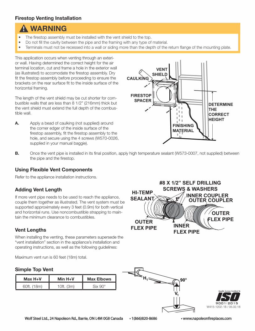
This application occurs when venting through an exteri-or wall. Having determined the correct height for the air terminal location, cut and frame a hole in the exterior wall (as illustrated) to accomodate the firestop assembly. Dry fit the firestop assembly before proceeding to ensure the brackets on the rear surface fit to the inside surface of the horizontal framing.
The length of the vent shield may be cut shorter for com-bustible walls that are less than 8 1/2” (216mm) thick but the vent shield must extend the full depth of the combus-tible wall.
A. Apply a bead of caulking (not supplied) around the corner edger of the inside surface of the firestop assembly, fit the firestop assembly to the hole, and secure using the 4 screws (W570-0026, supplied in your manual baggie).
B. Once the vent pipe is installed in its final position, apply high temperature sealant (W573-0007, not supplied) between the pipe and the firestop.
Using Flexible Vent ComponentsRefer to the appliance installation instructions.
Adding Vent LengthIf more vent pipe needs to be used to reach the appliance, couple them together as illustrated. The vent system must be supported approximately every 3 feet (0.9m) for both vertical and horizontal runs. Use noncombustible strapping to main-tain the minimum clearance to combustibles.
Vent LengthsWhen installing the venting, these parameters supersede the “vent installation” section in the appliance’s installation and operating instructions, as well as the following guidelines:
Maximum vent run is 60 feet (18m) total.
Simple Top Vent
Max H+V Min H+V Max Elbows60ft. (18m) 10ft. (3m) Six 90°
DETERMINETHECORRECTHEIGHT
CAULKING
FIRESTOPSPACER
VENTSHIELD
FINISHINGMATERIAL
HI-TEMPSEALANT
#8 X 1/2” SELF DRILLING SCREWS & WASHERS
INNER COUPLEROUTER COUPLER
OUTERFLEX PIPE INNER
FLEX PIPE
OUTERFLEX PIPE
DETERMINETHECORRECTHEIGHT
CAULKING
FIRESTOPSPACER
VENTSHIELD
FINISHINGMATERIAL
HI-TEMPSEALANT
#8 X 1/2” SELF DRILLING SCREWS & WASHERS
INNER COUPLEROUTER COUPLER
OUTERFLEX PIPE INNER
FLEX PIPE
OUTERFLEX PIPE
DETERMINETHECORRECTHEIGHT
CAULKING
FIRESTOPSPACER
VENTSHIELD
FINISHINGMATERIAL
HI-TEMPSEALANT
#8 X 1/2” SELF DRILLING SCREWS & WASHERS
INNER COUPLEROUTER COUPLER
OUTERFLEX PIPE INNER
FLEX PIPE
OUTERFLEX PIPE

W415-1202 / B / 05.02.18
Wolf Steel Ltd., 24 Napoleon Rd., Barrie, ON L4M 0G8 Canada • 1(866)820-8686 • www.napoleon�replaces.com
Multi-ElbowMulti-elbow installations are possible up to a maximum of six 90°.
MaxV1 + V2 + V3+H1 + H2 + H3
MinV1 + V2 + V3 +H1 + H2 + H3
Max Elbows
60ft. (18m) 10ft. (3m) Six 90°
Downward Vertical VentingDownward venting installations are only allowed when the appliance is set to Intermittent Pilot Ignition (I.P.I.) Electronic Ignition (E.I.).
MaxH1 + H2 + V
MinH1 + H2 + V
Max D Max Elbows
60ft. (18m) 10ft. (3m) 8ft. (2.4m) Six 90°
Venturi Adjustment
Venturi Adjustment Chart
Fuel C/HD4NG 1/16” (1.6mm)P 5/16” (7.9mm)
Restrictor Plate InstallationVertical installations may display a very active flame. If this appearance is not desirable, the vent exit may be restricted using a restrictor vent kit (the appropriate kit has been supplied). This will reduce the velocity of the exhaust gases, slowing down the flame pattern and creating a more traditional, gentle flame appearance. Specific instructions are included with the kit.
This appliance has an air shutter that has been factory set open according to the chart below:Regardless of venturi orientation, closing the air shutter will cause a more yellow flame, but can lead to carbonization. Opening the air shutter will cause a more blue flame, but can cause flame lifting from the burner ports. The flame may not appear yellow immediately; allow 15 to 30 minutes for the final flame colour to be established. AIR SHUTTER ADJUSTMENT MUST ONLY BE DONE BY A QUALIFIED INSTALLER!
AIR SHUTTER OPENING
VENTURIBURNER
ORIFICE
33.1
It is important that the orifice is securely inserted into the venturi.note:
If an anti-condensation switch is being used, downward vertical venting is not allowed.
note:
Wolf Steel Ltd., 24 Napoleon Rd., Barrie, ON L4M 0G8 Canada • 1(866)820-8686 • www.napoleonfoyers.comW415-1202 / B / 05.02.18
:
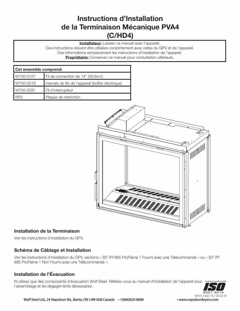
Instructions d’Installation de la Terminaison Mécanique PVA4
(C/HD4)Installateur: Laissez ce manuel avec l’appareil.
Ces instructions doivent être utilisées conjointement avec celles du GPV et de l’appareil.Ces informations remplacement les instructions d’installation de l’appareil.
Propriétaire: Conservez ce manuel pour consultation ultérieure.
Cet ensemble comprend:W750-0127 Fil de connection de 14” (35,6cm)W750-0218 Harnais de fils de l’appareil (boîtier électrique)W750-0291 Fil d’interrupteurRP5 Plaque de restriction
Installation de la TerminaisonVoir les instructions d’installation du GPV.
Schéma de Câblage et InstallationVoir les instructions d’installation du GPV, sections « SIT IPI 885 ProFlame 1 Fourni avec une Télécommande » ou « SIT IPI 885 ProFlame 1 Non Fourni avec une Télécommande ».
Installation de l’ÉvacuationN’utilisez que des composants d’évacuation Wolf Steel. Référez-vous au manuel d’installation de l’appareil pourl’assemblage et les dégagements décessaires.

! AVERTISSEMENT• L’espaceur coupe-feu doit être installé avec l’écran protecteur orienté vers le haut.• Ne remplissez l’espace entre le conduit d’évent et le manchon de l’espaceur coupe-feu avec aucun type de matériau.• Les terminaisons ne doivent pas être enchâssés dans le mur ou le revêtement extérieur plus que l’épaisseur de la
bride de la plaque de montage.
Wolf Steel Ltd., 24 Napoleon Rd., Barrie, ON L4M 0G8 Canada • 1(866)820-8686 • www.napoleonfoyers.com
:
W415-1202 / B / 05.02.18
Installation de l’Évacuation et de l’Espaceur Coupe-Feu
Cette configuration s’applique lorsque le conduit d’évent traverse un mur extérieur. Une fois que vous aurez déter-miné la hauteur exacte pour l’emplacement de la termi-naison, découpez et charpentez une ouverture dans le mur extérieure tel qu’illustré pour permettre l’installation de l’espaceur coupe-feu. Avant de continuer, placez l’espa-ceur coupe-feu dans l’ouverture pour vous assurer que les supports sur la surface arrière soient placés à l’intérieure de la pièce de charpente horizontale.
La protecteur de conduit d’évacuation peut coupé plus court pour les murs combustibles dont l’épaisseur est moins de 8 1/2” (216mm) mais le protecteur de conduit d’évacuation doit se prolonger sur toute la profondeur du mur combusti-ble.
A. Appliquez un joint de calfeutrage (non fourni) tout autour de la bordure de la face intérieure de l’espaceur, installez l’espaceur dans le trou, et fixez à l’aide des quatre vis (W570-0026, fournies dans le sac de votre manuel).B. Une fois que le conduit d’évent est en place, appliquez du scellant à haute température (W573-0002, non fouri) entre le conduit d’évent et l’espaceur coupe-feu.
SCELLANT À HAUTE
TEMPÉRATURE
VIS AUTO-PERCEUSES #8 X 1/2” ET RONDELLES
BAGUE D’ACCOUPLEMENTINTÉRIEUREBAGUE D’ACCOUPLEMENT
EXTÉRIEURE
GAINE FLEXIBLE EXTÉRIEURE GAINE
FLEXIBLE INTÉRIEURE
GAINE FLEXIBLE EXTÉRIEURE
DÉTERMINEZLA BONNEHAUTEUR
CALFEUTRAGE
ESPACEUR COUPE-FEU
PROTECTEURDE CONDUIT
D’ÉVACUATION
MATÉRIAUDE FINITION
Utilisations de Composants Flexibles d’ÉvacuationRéférez-vous au manuel d’installation de l’appareil.
Ajout de Longueur d’ÉventSi plus de sections de gaine doivent être utilisées pour attein-dre l’appareil, raccordez-les ensemble tel qu’illustré. Les courses horizontales et verticales du système d’évacuation doivent être supportés à chaque 3 pieds (0,9m) approximativement. Utilisez des supports incombustibles afin de maintenir le dégagement minimal aux matériaux combustibles.
SCELLANT À HAUTE
TEMPÉRATURE
VIS AUTO-PERCEUSES #8 X 1/2” ET RONDELLES
BAGUE D’ACCOUPLEMENTINTÉRIEUREBAGUE D’ACCOUPLEMENT
EXTÉRIEURE
GAINE FLEXIBLE EXTÉRIEURE GAINE
FLEXIBLE INTÉRIEURE
GAINE FLEXIBLE EXTÉRIEURE
DÉTERMINEZLA BONNEHAUTEUR
CALFEUTRAGE
ESPACEUR COUPE-FEU
PROTECTEURDE CONDUIT
D’ÉVACUATION
MATÉRIAUDE FINITION
Longueur des Conduits d’ÉvacuationLors de l’installation de l’évacuation, les paramètres suivants remplaceront la section « installation des évents » dans le manu-el d’instructions d’installation et d’opération de l’appareil:
La déviation maximale est de 60 pieds (18m) en tout.
Évacuation sur le Dessus, Configuration Simple
H+V Max H+V Min Coudes Max60pi. (18m) 10pi. (3m) Six 90°
SCELLANT À HAUTE
TEMPÉRATURE
VIS AUTO-PERCEUSES #8 X 1/2” ET RONDELLES
BAGUE D’ACCOUPLEMENTINTÉRIEUREBAGUE D’ACCOUPLEMENT
EXTÉRIEURE
GAINE FLEXIBLE EXTÉRIEURE GAINE
FLEXIBLE INTÉRIEURE
GAINE FLEXIBLE EXTÉRIEURE
DÉTERMINEZLA BONNEHAUTEUR
CALFEUTRAGE
ESPACEUR COUPE-FEU
PROTECTEURDE CONDUIT
D’ÉVACUATION
MATÉRIAUDE FINITION

Coudes MultiplesLes installations à coudes multiples sont possibles jusqu’à un maximum de six coudes de 90°.
V1 + V2 + V3+H1 + H2 + H3
Max
V1 + V2 + V3 +H1 + H2 + H3
Min
Coudes Max
60pi. (18m) 10pi. (3m) Six 90°
Évacuation Verticale DescendanteLes installations d’évacuation descendantes sont seulement permises quand l’appareil est réglé à Allumage Intermittent de la Veilleuse (I.P.I.) Allum-age Électronique (E.I.).
H1 + H2 + VMin
H1 + H2 + VMin
DMax
CoudesMax
60pi. (18m) 10pi. (3m) 8pi. (2,4m) Six 90°
Réglage du VenturiL’ouverture du volet d’air a été préréglée en usine selon le tableau ci-dessous:Indépendamment de l’orientation du venturi, plus le volet est fermé, plus la flamme est jaune et aura tendance à causer des dépôts de carbone. Plus le volet est ouvert, plus la flamme est bleue et plus elle a tendance à se détacher des orifices du brûleur. La flamme peut ne pas être jaune immédiatement; allouez de 15 à 30 minutes pour que la couleur finale de la flamme se stabilise.LE RÉGLAGE DU VOLET D’AIR DOIT ÊTRE EXÉCUTÉ PAR UN TECHICIEN OU INSTALLATEUR QUALIFIÉ!
OUVERTURE DU VOLET D’AIR
VENTURI
INJECTEUR
33.1
Il est important que l’injecteur soit correctement inséré dans le venturi.note:
Tableau du Réglage du Venturi
Combustible C/HD4GN 1/16” (1,6mm)P 5/16” (7,9mm)
Installation de la Plaque de RestrictionCertaines configurations d’évacuation verticales peuvent avoir une flamme très active. Si cette apparence n’est pas désirée, la sortie du conduit d’évacuation doit être réduite en utilisant une plaque de restriction (la trousse appropriée a été fournie). Ceci diminuera la vélocité des gaz de combustion, ralentissant ainsi le mouvement de la flamme et créant une apparence plus traditionnelle. Les instructions sont incluses avec l’ensemble.
:
W415-1202 / B / 05.02.18
Wolf Steel Ltd., 24 Napoleon Rd., Barrie, ON L4M 0G8 Canada • 1(866)820-8686 • www.napoleonfoyers.com
L’évacuation verticale descendante n’est pas permise avec l’utilisation d’un interrupteur anti-condensation.
note: