pvc schedule 80 pipe and fittings pvc schedule 40 pipe and ... · 6 schedule 80 fittings tee s x s...
TRANSCRIPT

DIMENSIONAL CATALOG
Pres
sure
© 2001-2019 Charlotte Pipe and Foundry Company
DC-PR
PVC Schedule 80 Pipe and Fittings
PVC Schedule 40 Pipe and Fittings
FlowGuard Gold® CPVC CTS Pipe and Fittings
(Updated July 22, 2019)

Charlotte Pipe and “You can’t beat the system” are registered trademarks of Charlotte Pipe and Foundry Company.
FlowGuard Gold is a registered trademark of Lubrizol Coporation.
PagePipe Data - PVC Schedule 80, Plain End................... 3
Pipe Data - PVC Schedule 80, Belled End ................. 4
Schedule 80 and Schedule 40 Tapered Socket Dimensions ........................................................ 5
American National Standard Taper Pipe Threads ....... 5
PVC Schedule 80 Fittings Dimensions and Weights .......................................................6-24
Pipe Data - PVC Schedule 40, Plain End................. 25
Pipe Data - PVC Schedule 40, Belled End ............... 26
Pipe Data - PVC Well Casing and SDR Pipe ............ 27
PVC Schedule 40 Fittings Dimensions and Weights ....................................................28-45
Pipe Data - FlowGuard® CPVC CTS SDR 11 ........... 46
FlowGuard Gold® CPVC CTS Fitting Dimensions ..... 47
FlowGuard Gold® CPVC CTS Fittings Dimensions and Weights ..............................48-58Certification .....................................................59-60Limited Warranty ................................................... 61FlowGuard Gold® Limited Warranty ........................ 62
PRESSURE PIPE AND FITTINGS DIMENSIONAL CATALOG
TABLE OF CONTENTS
Download our Tech Tools App for dimensional info, tech calculators and more on your mobile device.

3
PVC
SCHEDULE
80
PIPE
Pipe Data
PVC 10002 1⁄4” x 20’ 04920 15140’ 0.540 .119 1130 PSI 10.0 PVC 10003 3⁄8” x 20’ 04917 9360’ 0.675 .126 920 PSI 13.8 PVC 10005 1⁄2” x 20’ 03968 6880’ 0.840 .147 850 PSI 20.3 PVC 10007 3⁄4” x 20’ 03969 4200’ 1.050 .154 690 PSI 27.5 PVC 10010 1” x 20’ 03970 3540’ 1.315 .179 630 PSI 40.5 PVC 10012 11⁄4” x 20’ 03973 4240’ 1.660 .191 520 PSI 55.9 PVC 10015 11⁄2” x 20’ 03976 3300’ 1.900 .200 470 PSI 67.7 PVC 10020 2” x 20’ 03977 1980’ 2.375 .218 400 PSI 93.6 PVC 10025 21⁄2” x 20’ 03978 1360’ 2.875 .276 420 PSI 142.8 PVC 10030 3” x 20’ 03979 960’ 3.500 .300 370 PSI 194.2 PVC 10040 4” x 20’ 03980 1140’ 4.500 .337 320 PSI 279.3 PVC 10050 5” x 20’ 04831 760’ 5.563 .375 290 PSI 387.3 PVC 10060 6” x 20’ 03981 520’ 6.625 .432 280 PSI 532.7 PVC 10080 8” x 20’ 04175 300’ 8.625 .500 250 PSI 808.9 PVC 10100 10” x 20’ 04768 160’ 10.750 .593 230 PSI 1199.3 PVC 10120 12” x 20’ 04770 120’ 12.750 .687 230 PSI 1650.1 PVC 10140 14” x 20’ 04816 60’ 14.000 .750 220 PSI 1930.0 PVC 10160 16” x 20’ 04919 60’ 16.000 .843 220 PSI 2544.1
PVC Schedule 80 Pipe, Type 1, Grade 1 - Plain End
PVC SCHEDULE 40 (WHITE) PLAIN END PVC 1120 ASTM D 2665 PVC SCHEDULE 80 (GRAY) PLAIN END PVC 1120 MAX WORK PART NO. NOM. SIZE UPC # QTY. PER AVG. OD MIN. WALL PRESSURE AT WT. PER 611942- SKID (IN.) (IN.) 23° C OR 73° F 100 FT. (LBS.)
MADE INU.S.A.
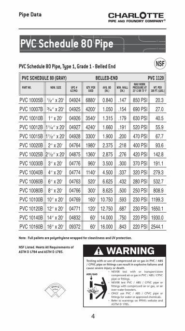
Note: Full pallets are polyethylene wrapped for cleanliness and UV protection.
NSF Listed. Meets All Requirements of ASTM D 1784 and ASTM D 1785.
PVC Schedule 80 Pipe
Testing with or use of compressed air or gas in PVC / ABS / CPVC pipe or fittings can result in explosive failures and cause severe injury or death.
• NEVER test with or transport/store compressed air or gas in PVC / ABS / CPVC pipe or fittings.
• NEVER test PVC / ABS / CPVC pipe or fittings with compressed air or gas, or air over water boosters.
• ONLY use PVC / ABS / CPVC pipe or fittings for water or approved chemicals.
• Refer to warnings on PPFA’s website and ASTM D 1785.
4
Pipe Data
MADE INU.S.A.
Note: Full pallets are polyethylene wrapped for cleanliness and UV protection.
NSF Listed. Meets All Requirements of ASTM D 1784 and ASTM D 1785.
PVC 10005B 1⁄2” x 20’ 04924 6880’ 0.840 .147 850 PSI 20.3 PVC 10007B 3⁄4” x 20’ 04925 4200’ 1.050 .154 690 PSI 27.0 PVC 10010B 1” x 20’ 04926 3540’ 1.315 .179 630 PSI 40.5 PVC 10012B 11⁄4” x 20’ 04927 4240’ 1.660 .191 520 PSI 55.9 PVC 10015B 11⁄2” x 20’ 04928 3300’ 1.900 .200 470 PSI 67.7 PVC 10020B 2” x 20’ 04764 1980’ 2.375 .218 400 PSI 93.6 PVC 10025B 21⁄2” x 20’ 04875 1360’ 2.875 .276 420 PSI 142.8 PVC 10030B 3” x 20’ 04776 960’ 3.500 .300 370 PSI 191.1 PVC 10040B 4” x 20’ 04774 1140’ 4.500 .337 320 PSI 279.3 PVC 10060B 6” x 20’ 04763 520’ 6.625 .432 280 PSI 532.7 PVC 10080B 8” x 20’ 04766 300’ 8.625 .500 250 PSI 808.9 PVC 10100B 10” x 20’ 04769 160’ 10.750 .593 230 PSI 1199.3 PVC 10120B 12” x 20’ 04771 120’ 12.750 .687 230 PSI 1650.1 PVC 10140B 14” x 20’ 04832 60’ 14.000 .750 220 PSI 1930.0 PVC 10160B 16” x 20’ 09372 60’ 16.000 .843 220 PSI 2544.1
PVC Schedule 80 Pipe, Type 1, Grade 1 - Belled End
PVC SCHEDULE 40 (WHITE) PLAIN END PVC 1120 ASTM D 2665 PVC SCHEDULE 80 (GRAY) BELLED-END PVC 1120
PVC Schedule 80 Pipe
Testing with or use of compressed air or gas in PVC / ABS / CPVC pipe or fittings can result in explosive failures and cause severe injury or death.
• NEVER test with or transport/store compressed air or gas in PVC / ABS / CPVC pipe or fittings.
• NEVER test PVC / ABS / CPVC pipe or fittings with compressed air or gas, or air over water boosters.
• ONLY use PVC / ABS / CPVC pipe or fittings for water or approved chemicals.
• Refer to warnings on PPFA’s website and ASTM D 1785.
MAX WORK PART NO. NOM. SIZE UPC # QTY. PER AVG. OD MIN. WALL PRESSURE AT WT. PER 611942- SKID (IN.) (IN.) 23° C OR 73° F 100 FT. (LBS.)

5
Schedule 80 Fittings
Schedule 80 and Schedule 40 Tapered Socket Dimensions
PVC SCHEDULE 80 - ASTM D 2467PVC SCHEDULE 40 - ASTM D 2466
American National StandardTaper Pipe Threads (NPT)ANSI / ASME B1.20.1, ASTM D 2467, ASTM F 1498
Effective Nominal Thread Threads Pitch of Size Length (L) Per Inch Thread (P)
1⁄2 0.5337 14.0 .07143 3⁄4 0.5457 14.0 .07143 1 0.6828 11.5 .08696 11⁄4 0.7068 11.5 .08696 11⁄2 0.7235 11.5 .08696 2 0.7565 11.5 .08696 21⁄2 1.1375 8.0 .12500 3 1.2000 8.0 .12500 4 1.3000 8.0 .12500
Schedule 80 and Schedule 40 Socket Diameter Schedule 80 Schedule 40 Nominal Entrance Bottom Tolerance Socket Length Socket Length Size A B C (Minimum) C (Minimum)
1⁄2 0.848 0.836 ±0.004 0.875 0.688 3⁄4 1.058 1.046 ±0.004 1.000 0.719 1 1.325 1.310 ±0.005 1.125 0.875 11⁄4 1.670 1.655 ±0.005 1.290 0.938 11⁄2 1.912 1.894 ±0.006 1.375 1.094 2 2.387 2.369 ±0.006 1.500 1.156 21⁄2 2.889 2.868 ±0.007 1.750 1.750 3 3.516 3.492 ±0.008 1.875 1.875 4 4.518 4.491 ±0.009 2.250 2.000 6 6.647 6.614 ±0.011 3.000 3.000 8 8.655 8.610 ±0.015 4.000 4.000 10 10.780 10.735 ±0.015 5.000 5.000 12 12.780 12.735 ±0.015 6.000 6.000
SCHEDULE
80
FITTINGS

6
Schedule 80 Fittings
Tee S x S x S
PVC PART NO. 8400
• S = SOCKET, SPG = SPIGOT, MPT = MALE PIPE THREAD, FPT = FEMALE PIPE
THREAD
• ALL DIMENSIONS ARE IN INCHES.
TOLERANCES
S = (SOCKET LENGTH) MINIMUM
G = (LAYING LENGTH) INTERSECTION OF CENTER LINES TO BOTTOM OF SOCKET/
THREAD, 90° ELBOWS, TEES, CROSSES, ± 1/32”
H = INTERSECTION OF CENTER LINES TO FACE OF FITTINGS; 90° ELBOWS, TEES,
CROSSES, ± 1/32”
J = (LAYING LENGTH) INTERSECTION OF CENTER LINES TO BOTTOM OF SOCKET/
THREAD; 45° ELBOWS, ± 1/32”
L = OVERALL LENGTH OF FITTINGS, (INCLUDING CAPS), ± 1/16”
M = OUTSIDE DIAMETER OF SOCKET/THREAD HUB, ± 1/16”
N = SOCKET/THREAD BOTTOM TO SOCKET/THREAD BOTTOM; COUPLINGS, ± 1/16”
• DIMENSIONS ARE SUBJECT TO CHANGE WITHOUT NOTIFICATION.
Universal Approx Size Part Number L H G Wt. (Lbs.)
1⁄2 801-005 215⁄16 115⁄32 19⁄32 0.11
3⁄4 801-007 37⁄16 123⁄32 11⁄16 0.17
1 801-010 4 2 27⁄32 0.29
11⁄4 801-012 49⁄16 29⁄32 1 0.42 11⁄2 801-015 47⁄8 27⁄16 11⁄32 0.51 2 801-020 53⁄4 27⁄8 15⁄16 0.84 21⁄2 801-025 615⁄16 315⁄32 121⁄32 1.49 3 801-030 71⁄2 33⁄4 127⁄32 2.38 4 801-040 93⁄8 411⁄16 27⁄16 3.76 6 801-060 141⁄8 71⁄16 41⁄32 10.75 8 801-080 1719⁄32 813⁄16 43⁄4 20.13

7
Universal Apprpx. Size Part Number L H H1 G G1 Wt. (Lbs.)
3⁄4 x 3⁄4 x
1⁄2 801-101 33⁄16 119⁄32 121⁄32 9⁄16 3⁄4 0.15
1 x 1 x 1⁄2 801-130 315⁄32 13⁄4 119⁄32 19⁄32
11⁄16 0.23 1 x 1 x
3⁄4 801-131 321⁄32 113⁄16 127⁄32 11⁄16 27⁄32 0.23
11⁄4 x 11⁄4 x 1 801-168 417⁄64 21⁄8 21⁄16 13⁄16 15⁄16 0.36
11⁄2 x 11⁄2 x 3⁄4 801-210 45⁄32 23⁄32 21⁄32 11⁄16 1 0.36
11⁄2 x 11⁄2 x 1 801-211 41⁄2 21⁄4 29⁄32 7⁄8 15⁄32 0.42 11⁄2 x 11⁄2 x 11⁄4 801-212 51⁄8 25⁄8 25⁄16 13⁄16 11⁄32 0.51 2 x 2 x
1⁄2 801-247 45⁄32 23⁄32 25⁄32 9⁄16 11⁄4 0.44 2 x 2 x
3⁄4 801-248 413⁄32 27⁄32 29⁄32 11⁄16 11⁄4 0.48 2 x 2 x 1 801-249 43⁄4 23⁄8 29⁄16 7⁄8 113⁄32 0.60 2 x 2 x 11⁄2 801-251 53⁄8 211⁄16 213⁄16 13⁄16 113⁄32 0.73 3 x 3 x 2 801-338 65⁄8 35⁄16 311⁄32 17⁄16 113⁄16 1.62 4 x 4x 2 801-420 79⁄16 325⁄32 41⁄8 11⁄2 219⁄32 2.77 4 x 4x 3 801-422 85⁄8 45⁄16 45⁄32 21⁄16 219⁄32 3.13 6x 6 x 2 801-528 917⁄32 425⁄32 51⁄16 13⁄4 317⁄32 6.16 6x 6 x 4 801-532 111⁄2 53⁄4 6 223⁄32 323⁄32 7.21 8x8x6 801-585 155⁄8 713⁄16 71⁄8 33⁄4 41⁄16 15.29
Schedule 80 Fittings
Reducing Tee S x S x S
PVC PART NO. 8400
SCHEDULE
80
FITTINGS

8
Schedule 80 Fittings
Universal Apprpx. Size Part Number L H G H1 G1 Wt. (Lbs.) 1⁄2 802-005 213⁄16 113⁄32
17⁄32 111⁄32 19⁄32 0.15
3⁄4 802-007 33⁄16 121⁄32 21⁄32 117⁄32 25⁄32 0.22
1 802-010 311⁄16 127⁄32 23⁄32 113⁄16 13⁄16 0.34
Tee S x S x FPT
PVC PART NO. 8401
Universal Approx. Size Part Number L H G Wt. (Lbs.)
1⁄2 805-005 25⁄8 15⁄16 17⁄32 0.14
3⁄4 805-007 215⁄16 115⁄32 21⁄32 0.19
1 805-010 37⁄16 123⁄32 3⁄4 0.34
11⁄4 805-012 37⁄8 115⁄16 15⁄16 0.48
11⁄2 805-015 43⁄16 23⁄32 11⁄32 0.64 2 805-020 43⁄4 23⁄8 15⁄16 0.90 3 805-030 71⁄16 317⁄32 129⁄32 2.73 4 805-040 87⁄16 47⁄32 215⁄32 4.49
Tee FPT x FPT x FPT
PVC PART NO. 8402

9
Universal Approx. Size Part Number H G Wt. (Lbs.)
1⁄2 806-005 115⁄32 19⁄32 0.08 3⁄4 806-007 111⁄16
11⁄16 0.13 1 806-010 2
27⁄32 0.19 11⁄4 806-012 29⁄32 1 0.32 11⁄2 806-015 27⁄16 11⁄32 0.42 2 806-020 227⁄32 15⁄16 0.63 21⁄2 806-025 37⁄16 121⁄32 1.13 3 806-030 33⁄4 127⁄32 1.60 4 806-040 411⁄16 27⁄16 2.85 6 806-060 611⁄16 311⁄16 8.27 8 806-080 819⁄32 419⁄32 15.46
Schedule 80 Fittings
90 Degree Elbow S x S
PVC PART NO. 8300
90 Degree Elbow S x FPT
PVC PART NO. 8301
Universal Approx. Size Part Number H G H1 G1 Wt. (Lbs.)
1⁄2 807-005 13⁄8 1⁄2 113⁄32 22⁄32 .138 3⁄4 807-007 121⁄32 5⁄8 15⁄8 13⁄16 .173 1 807-010 127⁄32 23⁄32 125⁄32 27⁄32 .265 11⁄4 807-012 21⁄4 11⁄4 2 1 .434 11⁄2 807-015 23⁄8 1 21⁄8 11⁄16 .562 2 807-020 23⁄4 11⁄4 27⁄16 17⁄16 .802
SCHEDULE
80
FITTINGS

10
Schedule 80 Fittings
Universal Approx. Size Part Number T G H Wt. (Lbs.)
1⁄2 808-005 3⁄4 21⁄32 113⁄32 0.11
3⁄4 808-007 25⁄32 27⁄32 15⁄8 0.18
1 808-010 31⁄32 3⁄4 123⁄32 0.26
11⁄4 808-012 1 31⁄32 131⁄32 0.42
11⁄2 808-015 11⁄16 15⁄32 27⁄32 0.54 2 808-020 13⁄32 113⁄32 21⁄2 0.82 3 808-030 15⁄8 115⁄16 39⁄16 2.30 4 808-040 111⁄16 21⁄2 43⁄16 3.62
90 Degree Elbow FPT x FPT
PVC PART NO. 8302
Universal Approx. Size Part Number H J Wt. (Lbs.)
1⁄2 817-005 15⁄32 1⁄4 0.07 3⁄4 817-007 111⁄32
5⁄16 0.10 1 817-010 115⁄32
5⁄16 0.16 11⁄4 817-012 111⁄16
13⁄32 0.22 11⁄2 817-015 17⁄8
1⁄2 0.30 2 817-020 25⁄32
21⁄32 0.48 21⁄2 817-025 21⁄2
23⁄32 0.83 3 817-030 211⁄16
25⁄32 1.16 4 817-040 39⁄16 19⁄32 2.21 6 817-060 5 2 5.50 8 817-080 61⁄4 21⁄4 10.42
45 Degree Elbow S x S
PVC PART NO. 8309

11
Schedule 80 Fittings
45 Degree Elbow FPT x FPT
PVC PART NO. 8312
Universal Approx. Size Part Number H J T Wt. (Lbs.)
1⁄2 819-005 11⁄32 9⁄32 3⁄4 0.07
3⁄4 819-007 11⁄8 11⁄32
25⁄32 0.10 1 819-010 111⁄32
3⁄8 31⁄32 0.16
11⁄4 819-012 17⁄16 7⁄16 1 0.23
11⁄2 819-015 19⁄16 17⁄32 11⁄32 0.31
2 819-020 13⁄4 23⁄32 11⁄32 0.46
3 819-030 23⁄4 7⁄8 17⁄8 1.74
Wye S x S x S
PVC PART NO. 8600
SCHEDULE
80
FITTINGS
*Maximum pressure rating is 250 psi at 73°F.
Universal Approx. Size Part Number L J H Wt. (Lbs.)
11⁄2* 875-015 31⁄16 11⁄16 213⁄32 0.65 2* 875-020 37⁄8 21⁄32 37⁄32 1.06 3* 875-030 415⁄16 11⁄16 69⁄16 2.51

12
Schedule 80 Fittings
Coupling S x S
PVC PART NO. 8100
Wye S x S x S
PVC PART NO. 8600
Universal Approx. Size Part Number L N Wt. (Lbs.)
1⁄2 829-005 115⁄16 1⁄8 0.05
3⁄4 829-007 23⁄16 1⁄8 0.08
1 829-010 27⁄16 1⁄8 0.12
11⁄4 829-012 211⁄16 1⁄8 0.17
11⁄2 829-015 215⁄16 1⁄8 0.23
2 829-020 33⁄16 1⁄8 0.33
21⁄2 829-025 33⁄4 3⁄16 0.57
3 829-030 4 3⁄16 0.84
4 829-040 43⁄4 3⁄16 1.35
6 829-060 69⁄32 1⁄4 3.46
8 829-080 81⁄4 1⁄4 6.61
**Maximum pressure rating is 150 psi at 73°F.
Universal Approx. Size Part Number L J H Wt. (Lbs)
4** 875-040 63⁄16 13⁄16 53⁄8 4.42 6** 875-060 93⁄8 113⁄32 731⁄32 11.95

13
Schedule 80 Fittings
Reducer Coupling S x S
PVC PART NO. 8100
Universal Approx. Size Part Number L N Wt. (Lbs.)
3⁄4 x 1⁄2 829-101 23⁄16 1⁄4 0.07
1 x 1⁄2 829-130 23⁄8 5⁄16 0.11
1 x 3⁄4 829-131 27⁄16 1⁄4 0.11
11⁄4 x 1 829-168 23⁄4 5⁄16 0.17 11⁄2 x 1 829-211 27⁄8 5⁄16 0.21 11⁄2 x 11⁄4 829-212 215⁄16 1⁄4 0.23 2 x 1 829-249 31⁄2 3⁄8 0.32 2 x 11⁄2 829-251 33⁄16 7⁄8 0.32 3 x 2 829-338 41⁄8 3⁄4 0.78 4 x 2 829-420 51⁄8 15⁄16 1.32 4x 3 829-422 51⁄8 15⁄16 1.38 6 x 4 829-532 65⁄8 13⁄8 3.08
SCHEDULE
80
FITTINGS
Coupling FPT x FPT
PVC PART NO. 8102
Universal Approx. Size Part Number L N Wt. (Lbs.)
1⁄2 830-005 15⁄8 1⁄8 0.08
3⁄4 830-007 111⁄16 1⁄8 0.09
1 830-010 21⁄16 1⁄8 0.15
11⁄4 830-012 23⁄16 1⁄8 0.23
11⁄2 830-015 21⁄4 3⁄16 0.28
2 830-020 25⁄16 3⁄16 0.36
3 830-030 31⁄2 1⁄8 1.09
4 830-040 35⁄8 1⁄8 1.61

14
Schedule 80 Fittings
Female Adapter S x FPT
PVC PART NO. 8101
Universal Approx. Size Part Number L N Wt. (Lbs.)
1⁄2 835-005 125⁄32 3⁄32 0.07
3⁄4 835-007 115⁄16 3⁄32 0.10
1 835-010 29⁄32 3⁄32 0.16
11⁄4 835-012 23⁄8 1⁄8 0.22
11⁄2 835-015 29⁄16 1⁄8 0.27
2 835-020 223⁄32 3⁄32 0.39
21⁄2 835-025 319⁄32 7⁄32 0.73
3 835-030 33⁄4 7⁄32 0.96
4 835-040 41⁄4 1⁄4 1.52
Male Adapter S x MPT
PVC PART NO. 8109
Universal Approx. Size Part Number L N Wt. (Lbs.)
1⁄2 836-005 113⁄16 3⁄16 0.05
3⁄4 836-007 2 1⁄4 0.06
1 836-010 23⁄8 3⁄16 0.10
11⁄4 836-012 21⁄2 1⁄4 0.15
11⁄2 836-015 25⁄8 1⁄4 0.19
2 836-020 27⁄8 9⁄32 0.27
21⁄2 836-025 311⁄16 11⁄32 0.50
3 836-030 37⁄8 3⁄8 0.73
4 836-040 41⁄2 7⁄16 1.40

15
Schedule 80 Fittings
Reducer Bushing, Flush StyleSPG x S
PVC PART NO. 8107
Universal Approx. Size Part Number L N Wt. (Lbs.)
3⁄4 x 1⁄2 837-101 19⁄32
13⁄32 0.02 1 x
1⁄2 837-130 113⁄32 17⁄32 0.07
1 x 3⁄4 837-131 113⁄32
13⁄32 0.04 11⁄4 x
1⁄2 837-166 11⁄2 5⁄8 0.11
11⁄4 x 3⁄4 837-167 11⁄2
1⁄2 0.11 11⁄4 x 1 837-168 119⁄32
15⁄32 0.08 11⁄2 x
1⁄2 837-209 123⁄32 27⁄32 0.15
11⁄2 x 3⁄4 837-210 123⁄32
23⁄32 0.20 11⁄2 x 1 837-211 123⁄32
19⁄32 0.14 11⁄2 x 11⁄4 837-212 123⁄32
15⁄32 0.08 2 x
1⁄2 837-247 17⁄8 1 0.21 2 x
3⁄4 837-248 17⁄8 7⁄8 0.22
2 x 1 837-249 17⁄8 3⁄4 0.24
2 x 11⁄4 837-250 17⁄8 5⁄8 0.24
2 x 11⁄2 837-251 129⁄32 17⁄32 0.17
21⁄2 x 1 837-289 25⁄32 1 0.46 21⁄2 x 11⁄4 837-290 25⁄32
29⁄32 0.48 21⁄2 x 11⁄2 837-291 25⁄32
25⁄32 0.39 21⁄2 x 2 837-292 25⁄32
21⁄32 0.28 3 x 1 837-335 21⁄4 11⁄8 0.67 3 x 11⁄4 837-336 21⁄4 1 0.66 3 x 11⁄2 837-337 21⁄4
7⁄8 0.64 3 x 2 837-338 21⁄4
3⁄4 0.59 3 x 21⁄2 837-339 21⁄4
1⁄2 0.42 4 x 2 837-420 225⁄32
9⁄32 1.10 4x 3 837-422 225⁄32
29⁄32 0.76 6 x 3 837-530 317⁄32 111⁄32 2.60 6 x 4 837-532 317⁄32 19⁄32 2.50 8 x 6 837-585 415⁄16 17⁄8 5.52
SCHEDULE
80
FITTINGS

16
Schedule 80 Fittings
Reducer Bushing, Flush StyleSPG x FPT
PVC PART NO. 8108
Universal Approx. Size Part Number L SPG N Wt. (Lbs.)
3⁄4 x 1⁄2 838-101 11⁄4 11⁄32 1⁄2 0.03
1 x 1⁄2 838-130 17⁄16 15⁄32 11⁄16 0.06
1 x 3⁄4 838-131 13⁄8 15⁄32 19⁄32 0.04
11⁄4 x 1 838-168 19⁄16 19⁄32 9⁄16 0.09 11⁄2 x
3⁄4 838-210 13⁄4 113⁄32 19⁄32 0.16 11⁄2 x 1 838-211 13⁄4 113⁄32 11⁄32 0.15 11⁄2 x 11⁄4 838-212 121⁄32 113⁄32 21⁄32 0.10 2 x
3⁄4 838-248 17⁄8 117⁄32 13⁄32 0.23 2 x 1 838-249 17⁄8 117⁄32 27⁄32 0.28 2 x 11⁄4 838-250 129⁄32 117⁄32 13⁄32 0.24 2 x 11⁄2 838-251 129⁄32 117⁄32 7⁄8 0.19 21⁄2 x 2 838-292 23⁄16 125⁄32 15⁄32 0.31 3 x 2 838-338 29⁄32 129⁄32 17⁄32 0.64 3 x 21⁄2 838-339 29⁄32 129⁄32 27⁄32 0.49 4 x 2 838-420 211⁄16 25⁄16 111⁄16 1.11 4x 3 838-422 211⁄16 25⁄16 111⁄16 0.86

17
Schedule 80 Fittings
Reducer Bushing, Flush StyleMPT x FPT
PVC PART NO. 8200
Universal Approx. Size Part Number L N T1 Wt. (Lbs.)
3⁄4 x 1⁄2 839-101 1
9⁄32 3⁄4 0.02 1 x
1⁄2 839-130 11⁄4 17⁄32 3⁄4 0.05
1 x 3⁄4 839-131 11⁄4
9⁄32 3⁄4 0.04 11⁄4 x 1 839-168 15⁄16
5⁄16 1 0.06 11⁄2 x 1 839-211 13⁄8
5⁄16 1 0.11 11⁄2 x 11⁄4 839-212 13⁄8
5⁄16 1 0.07 2 x 1 839-249 17⁄16
5⁄16 1 0.19 2 x 11⁄2 839-251 17⁄16
5⁄16 1 0.13 21⁄2 x 2 839-292 115⁄16
3⁄8 1 0.24 3 x 2 839-338 2
3⁄8 1 0.51 4 x 2 839-420 211⁄16
3⁄8 25⁄16 0.99
SCHEDULE
80
FITTINGS

18
Schedule 80 Fittings
CapS
PVC PART NO. 8116
Universal Approx. Size Part Number S L Wt. (Lbs.)
1⁄2 847-005 7⁄8 13⁄8 0.04 3⁄4 847-007 1 115⁄32 0.06 1 847-010 11⁄8 15⁄8 0.09 11⁄4 847-012 11⁄4 113⁄16 0.15 11⁄2 847-015 13⁄8 2 0.18 2 847-020 11⁄2 25⁄32 0.28 21⁄2 847-025 13⁄4 219⁄32 0.51 3 847-030 17⁄8 213⁄16 0.72 4 847-040 21⁄4 35⁄16 1.20 6 847-060 3 411⁄16 3.10 8 847-080 4 67⁄16 6.11
Cap FPT
PVC PART NO. 8117
Universal Approx. Size Part Number T L Wt. (Lbs.)
1⁄2 848-005 3⁄4 11⁄32 0.05 3⁄4 848-007 7⁄8 17⁄32 0.06 1 848-010 1 13⁄8 0.11 11⁄4 848-012 1 117⁄32 0.15 11⁄2 848-015 11⁄32 15⁄8 0.19 2 848-020 11⁄32 113⁄16 0.29 3 848-030 17⁄16 223⁄32 0.80 4 848-040 11⁄2 3 1.30

19
Schedule 80 Fittings
Plug MPT
PVC PART NO. 8113
Universal Approx. Size Part Number L T Wt. (Lbs.)
1⁄2 850-005 15⁄16 3⁄4 0.02
3⁄4 850-007 1 3⁄4 0.03
1 850-010 11⁄4 1 0.05 11⁄4 850-012 15⁄16 1 0.07 11⁄2 850-015 15⁄16 1 0.10 2 850-020 11⁄2 11⁄16 0.18
SCHEDULE
80
FITTINGSFlange, One Piece**
S
PVC PART NO. 8500
Universal Size Part Number D L N R
1⁄2 851-005 31⁄2 11⁄8 7⁄32 9⁄16
3⁄4 851-007 37⁄8 13⁄16 3⁄16 9⁄16
1 851-010 41⁄4 15⁄16 3⁄16 5⁄8
11⁄4 851-012 419⁄32 17⁄16 3⁄16 11⁄16
* BOLT LENGTHS WERE CALCULATED USING TWO CHARLOTTE FLANGES. LENGTHS MAY VARY WHEN MATING WITH OTHER BRANDS OR ACCESSORIES. ** THE MAXIMUM WORKING PRESSURE IS 150 PSI AT 73°F.
BOLT CIRCLE BOLT HOLE NO. OF BOLT BOLT MIN. BOLT Approx. Size DIA. DIA. HOLES DIA. LENGTH* Wt. (Lbs.)
1⁄2 23⁄8 5⁄8 4
1⁄2 21⁄4 0.18 3⁄4 23⁄4
5⁄8 4 1⁄2 21⁄4 0.25
1 31⁄8 5⁄8 4
1⁄2 21⁄4 0.33 11⁄4 31⁄2
5⁄8 4 1⁄2 21⁄2 0.43

20
BOLT BOLT NO. OF BOLT MIN. BOLT Approx. Size CIRCLE DIA. HOLE DIA. BOLT HOLES DIA. LENGTH* Wt. (Lbs.)
1⁄2 23⁄8 5⁄8 4
1⁄2 21⁄4 0.19 3⁄4 23⁄4
5⁄8 4 1⁄2 21⁄4 0.25
1 31⁄8 5⁄8 4
1⁄2 21⁄4 0.33 11⁄4 31⁄2
5⁄8 4 1⁄2 21⁄2 0.44
11⁄2 37⁄8 5⁄8 4
1⁄2 21⁄2 0.57 2 43⁄4
3⁄4 4 5⁄8 3 0.92
Schedule 80 Fittings
* BOLT LENGTHS WERE CALCULATED USING TWO CHARLOTTE FLANGES. LENGTHS MAY VARY WHEN MATING WITH OTHER BRANDS OR ACCESSO-RIES. ** THE MAXIMUM WORKING PRESSURE IS 150 PSI AT 73°F.
Flange, One Piece**FPT
PVC PART NO. 8560
Universal Size Part Number D L N R
1⁄2 852-005 31⁄2 1 1⁄4 9⁄16
3⁄4 852-007 37⁄8 1 3⁄16 19⁄32
1 852-010 41⁄4 11⁄8 1⁄8 21⁄32
11⁄4 852-012 419⁄32 17⁄32 7⁄32 23⁄32
11⁄2 852-015 5 11⁄4 1⁄4 13⁄16
2 852-020 6 13⁄4 3⁄8 13⁄16

21
Schedule 80 Fittings
SCHEDULE
80
FITTINGS
* BOLT LENGTHS WERE CALCULATED USING TWO CHARLOTTE FLANGES. LENGTHS MAY VARY WHEN MATING WITH OTHER BRANDS OR ACCESSORIES. ** THE MAXIMUM WORKING PRESSURE IS 150 PSI AT 73°F.
Blind Flange, One Piece**PVC PART NO. 8510
Universal BOLT BOLT NO. OF MIN. Approx. Part CIRCLE HOLE BOLT BOLT BOLT Wt. Size Number D R DIA. DIA. HOLES DIA. LENGTH* (Lbs.)
2 853-020 57⁄8 13⁄16 4 3⁄4 3⁄4 4
5⁄8 3 0.84 3 853-030 77⁄16 29⁄32 6
3⁄4 4 5⁄8 33⁄4 1.58
4 853-040 91⁄32 11⁄16 7 1⁄2 3⁄4 8
5⁄8 31⁄2 2.50 6 853-060 111⁄32 11⁄8 91⁄2
15⁄16 8 3⁄4 33⁄4 3.69
8 853-080 131⁄2 115⁄32 1123⁄32 15⁄16 8
3⁄4 41⁄2 7.83

22
Schedule 80 Fittings
Van Stone Flange** S
PVC PART NO. 8530
* BOLT LENGTHS WERE CALCULATED USING TWO CHARLOTTE FLANGES. LENGTHS MAY VARY WHEN MATING WITH OTHER BRANDS OR ACCESSORIES. ** THE MAXIMUM WORKING PRESSURE IS 150 PSI AT 73°F.
Universal Size Part Number D L N R
11⁄2 854-015 415⁄16 19⁄16 3⁄32 23⁄32
2 854-020 57⁄8 123⁄32 3⁄32 13⁄16
21⁄2 854-025 611⁄16 131⁄32 1⁄8 29⁄32
3 854-030 77⁄16 21⁄8 1⁄8 29⁄32
4 854-040 91⁄32 25⁄8 1⁄8 11⁄16
6 854-060 1031⁄32 37⁄32 1⁄8 17⁄32
8 854-080 1311⁄32 45⁄16 3⁄16 11⁄2 10 854-100 16 511⁄16 5⁄8 111⁄16
12 854-120 19 75⁄16 9⁄16 111⁄16
BOLT CIRCLE BOLT HOLE NO. OF BOLT BOLT MIN. BOLT Approx. Size DIA. DIA. HOLES DIA. LENGTH* Wt. (Lbs.)
11⁄2 37⁄8 5⁄8 4
1⁄2 21⁄2 0.54 2 43⁄4
3⁄4 4 5⁄8 3 0.84
21⁄2 51⁄2 3⁄4 4
5⁄8 31⁄4 1.27 3 6
3⁄4 4 5⁄8 31⁄4 1.55
4 71⁄2 3⁄4 8
5⁄8 31⁄2 2.71 6 91⁄2
31⁄32 8 3⁄4 4 3.88
8 113⁄4 29⁄32 8
3⁄4 41⁄2 7.21 10 141⁄4 1 12
7⁄8 5 12.59 12 17 1 12
7⁄8 5 20.74

23
Schedule 80 Fittings
Union, with Viton® O-Ring Seal*S
PVC PART NO. 8700
Union, with EPDM O-Ring Seal*S
PVC PART NO. 8710
Universal Part Number with Viton with EPDM Approx. Size O-Ring Seal O-Ring Seal L N S Wt. (Lbs.)
1⁄2 857-005 897-005 21⁄8 5⁄16 29⁄32 0.18
3⁄4 857-007 897-007 27⁄16 7⁄16 1 0.26
1 857-010 897-010 25⁄8 3⁄8 11⁄8 0.36
11⁄4 857-012 897-012 215⁄16 7⁄16 11⁄4 0.52
11⁄2 857-015 897-015 33⁄16 7⁄16 13⁄8 0.57
2 857-020 897-020 321⁄32 21⁄32 11⁄2 0.90
3 857-030 897-030 51⁄8 15⁄16 129⁄32 2.22 * THE MAXIMUM WORKING PRESSURE IS 235 PSI AT 73°F.
SCHEDULE
80
FITTINGS
Union, with Viton® O-Ring Seal*FPT
PVC PART NO. 8800
Union, with EPDM O-Ring Seal*FPT
PVC PART NO. 8810 Universal Part Number with Viton with EPDM Approx. Size O-Ring Seal O-Ring Seal L N T Wt. (Lbs.)
1⁄2 858-005 898-005 23⁄16 1⁄2 15⁄16 0.19
3⁄4 858-007 898-007 213⁄32 9⁄16 13⁄32 0.27
1 858-010 898-010 25⁄8 9⁄16 13⁄32 0.40
11⁄4 858-012 898-012 231⁄32 23⁄32 11⁄4 0.58
11⁄2 858-015 898-015 31⁄8 23⁄32 111⁄32 0.67
2** 858-020 898-020 35⁄8 27⁄32 119⁄32 1.03
3† 858-030 898-030 51⁄8 13⁄4 111⁄16 2.49 * THE MAXIMUM WORKING PRESSURE IS 235 PSI AT 73°F. ** THE MAXIMUM WORKING PRESSURE IS 200 PSI AT 73°F. † THE MAXIMUM WORKING PRESSURE IS 185 PSI AT 73°F.

24
Schedule 80 Fittings
Union, with Viton® O-Ring Seal*S x FPT
PVC PART NO. 8820
Union, with EPDM O-Ring Seal*S x FPT
PVC PART NO. 8830
Universal Part Number with Viton with EPDM Approx. Size O-Ring Seal O-Ring Seal L N S Wt. (Lbs.)
1⁄2 859-005 899-005 21⁄8 5⁄16 15⁄16 0.18 3⁄4 859-007 899-007 27⁄16 7⁄16 13⁄32 0.27 1 859-010 899-010 25⁄8 3⁄8 13⁄32 0.37 11⁄4(N) 899-012 215⁄16 7⁄16 11⁄4 0.52 11⁄2 859-015 899-015 33⁄16 7⁄16 111⁄32 0.62 2** 859-020 899-020 321⁄32 21⁄32 119⁄32 0.98
* THE MAXIMUM WORKING PRESSURE IS 235 PSI AT 73°F. ** THE MAXIMUM WORKING PRESSURE IS 200 PSI AT 73°F.
(N) NOTE: AVAILABLE IN PART NO. PVC 8830 ONLY.

25
Pipe Data
PVC
SCHEDULE
40
PIPE
PVC 4005 1⁄2” x 10’ 06658 .840 .109 600 PSI 15.9 PVC 4005 1⁄2” x 20’ 03922 .840 .109 600 PSI 15.9 PVC 4007 3⁄4” x 10’ 06661 1.050 .113 480 PSI 21.1 PVC 4007 3⁄4” x 20’ 03925 1.050 .113 480 PSI 21.1 PVC 4010 1” x 10’ 06664 1.315 .133 450 PSI 31.3 PVC 4010 1” x 20’ 03928 1.315 .133 450 PSI 31.3 PVC 7100* 11⁄4” x 10’ 03945 1.660 .140 370 PSI 42.4 PVC 7100* 11⁄4” x 20’ 03946 1.660 .140 370 PSI 42.4 PVC 7112* 11⁄2” x 10’ 03947 1.900 .145 330 PSI 51.8 PVC 7112* 11⁄2” x 20’ 03948 1.900 .145 330 PSI 51.8 PVC 7200* 2” x 10’ 03949 2.375 .154 280 PSI 69.5 PVC 7200* 2” x 20’ 03950 2.375 .154 280 PSI 69.5 PVC 4025‡ 21⁄2” x 20’ 04205 2.875 .203 300 PSI 110.0 PVC 7300* 3” x 10’ 03951 3.500 .216 260 PSI 144.2 PVC 7300* 3” x 20’ 03952 3.500 .216 260 PSI 144.2 PVC 7400 † 4” x 10’ 03953 4.500 .237 220 PSI 205.5 PVC 7400 † 4” x 20’ 03954 4.500 .237 220 PSI 205.5 PVC 7500 † 5” x 20’ 04837 5.563 .258 190 PSI 272.5 PVC 7600 † 6” x 10’ 03955 6.625 .280 180 PSI 361.2 PVC 7600 † 6” x 20’ 03956 6.625 .280 180 PSI 361.2 PVC 7800 † 8” x 10’ 13087 8.625 .322 160 PSI 543.6 PVC 7800 † 8” x 20’ 03958 8.625 .322 160 PSI 543.6 PVC 7910 † 10” x 20’ 03959 10.750 .365 140 PSI 770.7 PVC 7912 † 12” x 20’ 03961 12.750 .406 130 PSI 1019.0 PVC 7914 † 14” x 20’ 04862 14.000 .437 130 PSI 1205.0 PVC 7916 † 16” x 20’ 04918 16.000 .500 130 PSI 1575.7
MADE INU.S.A.
PVC Schedule 40 Pipe - Plain End
PVC SCHEDULE 40 (WHITE) PLAIN END PVC 1120 ASTM D 2665
PVC Schedule 40 Pipe
PVC SCHEDULE 40 (WHITE) PLAIN END PVC 1120 ASTM D 1785 MAX WORK PART NO. NOM. SIZE UPC # AVG. OD MIN. WALL PRESSURE WT. PER 611942- (IN.) (IN.) AT 23° C OR 73° F 100 FT. (LBS.)
* Dual Marked ASTM D 1785 & ASTM D 2665. † Triple Marked ASTM D 1785 & ASTM D 2665 & ASTM F 480.‡ Dual Marked ASTM D 1785 & ASTM F 480.
NSF Listed. Meets All Requirements of ASTM D 1784 and ASTM D 1785.
Note: When ordering, please specify plain end or bell end.
Testing with or use of compressed air or gas in PVC / ABS / CPVC pipe or fittings can result in explosive failures and cause severe injury or death.
• NEVER test with or transport/store compressed air or gas in PVC / ABS / CPVC pipe or fittings.
• NEVER test PVC / ABS / CPVC pipe or fittings with compressed air or gas, or air over water boosters.
• ONLY use PVC / ABS / CPVC pipe or fittings for water or approved chemicals.
• Refer to warnings on PPFA’s website and ASTM D 1785.

26
Pipe Data
PVC 4005B** 1⁄2” x 10’ 04986 .840 .109 600 PSI 2.00 15.9 PVC 4005B** 1⁄2” x 20’ 03923 .840 .109 600 PSI 2.00 15.9 PVC 4007B** 3⁄4” x 10’ 04987 1.050 .113 480 PSI 2.25 21.1 PVC 4007B** 3⁄4” x 20’ 03926 1.050 .113 480 PSI 2.25 21.1 PVC 4010B** 1” x 10’ 04988 1.315 .133 450 PSI 2.50 31.3 PVC 4010B** 1” x 20’ 03929 1.315 .133 450 PSI 2.50 31.1 PVC 4012B§ 11⁄4” x 10’ 04989 1.660 .140 370 PSI 2.75 42.4 PVC 4012B§ 11⁄4” x 20’ 03930 1.660 .140 370 PSI 2.75 42.4 PVC 4015B§ 11⁄2” x 10’ 04990 1.900 .145 330 PSI 3.00 51.8 PVC 4015B§ 11⁄2” x 20’ 03931 1.900 .145 330 PSI 3.00 51.8 PVC 4020B† 2” x 10’ 04991 2.375 .154 280 PSI 4.00 69.5 PVC 4020B† 2” x 20’ 03932 2.375 .154 280 PSI 4.00 69.5 PVC 4025B‡ 21⁄2” x 20’ 04206 2.875 .203 300 PSI 4.00 110.0 PVC 7300B§ 3” x 10’ 04853 3.500 .216 260 PSI 4.00 147.6 PVC 4030B† 3” x 20’ 03933 3.500 .216 260 PSI 4.00 144.2 PVC 7400B§ 4” x 10’ 04835 4.500 .237 220 PSI 4.00 212.3 PVC 9400B† 4” x 20’ 03964 4.500 .237 220 PSI 5.00 210.6 PVC 7600B§ 6” x 10’ 04850 6.625 .280 180 PSI 6.50 379.3 PVC 9600B† 6” x 20’ 03965 6.625 .280 180 PSI 6.50 373.2 PVC 7800B† 8” x 10’ 09903 8.625 .322 160 PSI 7.00 556.9 PVC 9800B† 8” x 20’ 03967 8.625 .322 160 PSI 7.00 564.0 PVC 7910B† 10” x 20’ 03960 10.750 .365 140 PSI 9.00 781.4 PVC 7912B† 12” x 20’ 03962 12.750 .406 130 PSI 10.00 1033.2 PVC 7914B† 14” x 20’ 04863 14.000 .437 130 PSI 10.00 1221.8 PVC 7916B† 16” x 20’ 04929 16.000 .500 130 PSI 10.00 1594.5
MADE INU.S.A.
PVC Schedule 40 Pipe - Bell End*
PVC SCHEDULE 40 (WHITE) PLAIN END PVC 1120 ASTM D 2665 PVC SCHEDULE 40 (WHITE) BELL END PVC 1120 ASTM D 1785 MAX WORK PART NO. NOM. SIZE UPC # AVG. OD MIN. WALL PRESSURE AT BELL DEPTH WT. PER 611942- (IN.) (IN.) 23° C OR 73° F (IN.) 100 FT. (LBS.)
* Bell dimensions meet either ASTM D 2672 or ASTM F 480, depending upon pipe diameter** ASTM D 1785‡ Dual Marked ASTM D 1785 & ASTM F 480§ Dual Marked ASTM D 1785 & ASTM D 2665† Triple Marked ASTM D 1785 & ASTM D 2665 & ASTM F 480
Testing with or use of compressed air or gas in PVC / ABS / CPVC pipe or fittings can result in explosive failures and cause severe injury or death.
• NEVER test with or transport/store compressed air or gas in PVC / ABS / CPVC pipe or fittings.
• NEVER test PVC / ABS / CPVC pipe or fittings with compressed air or gas, or air over water boosters.
• ONLY use PVC / ABS / CPVC pipe or fittings for water or approved chemicals.
• Refer to warnings on PPFA’s website and ASTM D 1785.

27
Pipe Data
PVC
WELLCASING
&
SDR
PIPE
PVC 4020B 2” x 20’ 03932 2.375 .154 4.00 69.5 PVC 4025B 21⁄2” x 20’ 04206 2.875 .203 4.00 110.0 PVC 4030B 3” x 20’ 03933 3.500 .216 4.00 144.2 PVC 9400B 4” x 20’ 03964 4.500 .237 5.00 210.6 PVC 9600B 6” x 20’ 03965 6.625 .280 6.50 373.2 PVC 9800B 8” x 20’ 03967 8.625 .322 7.00 564.0 PVC 7910B 10” x 20’ 03960 10.750 .365 9.00 781.4PVC 7912B 12” x 20’ 03962 12.750 .406 10.00 1033.2PVC 7914B 14” x 20’ 04863 14.000 .437 10.00 1221.8PVC 7916B 16” x 20’ 04929 16.000 .500 10.00 1594.5
PVC Well CasingPVC SCHEDULE 40 (WHITE) PLAIN END PVC 1120 ASTM D 2665 PVC SCHEDULE 40 (WHITE) BELL END WELL CASING PVC 1120 ASTM F 480
PART NO. NOM. SIZE UPC # AVG. OD MIN. WALL BELL DEPTH WT. PER 611942- (IN.) (IN.) (IN.) 100 FT. (LBS.)
Note: When ordering, please specify plain end or bell end.
MADE INU.S.A.
PVC 23155B *1⁄2” x 20’ 03991 .840 .062 315 PSI 2.00 10.0 PVC 20007B 3⁄4” x 10’ 10742 1.050 .060 200 PSI 2.25 11.8 PVC 20007B 3⁄4” x 20’ 03984 1.050 .060 200 PSI 2.25 11.8 PVC 20010B 1” x 20’ 03986 1.315 .063 200 PSI 2.50 15.7 PVC 20012B 11⁄4” x 20’ 03987 1.660 .079 200 PSI 2.75 25.5 PVC 20015B 11⁄2” x 20’ 03988 1.900 .090 200 PSI 3.00 32.4 PVC 20020B 2” x 20’ 03989 2.375 .113 200 PSI 4.00 50.8*PR 315 / SDR 13.5
PVC SDR PipePVC SCHEDULE 40 (WHITE) PLAIN END PVC 1120 ASTM D 2665 PR 200 PVC 1120 BELL END ASTM D 2241 SDR 21
MAX WORK PART NO. NOM. SIZE UPC # AVG. OD MIN. WALL PRESSURE AT BELL DEPTH WT. PER 611942- (IN.) (IN.) 23° C OR 73° F (IN.) 100 FT. (LBS.)
PVC 16012B 11⁄4” x 20’ 04211 1.660 .064 160 PSI 2.75 21.5 PVC 16015B 11⁄2” x 20’ 04210 1.900 .073 160 PSI 3.00 26.6 PVC 16020B 2” x 20’ 04212 2.375 .091 160 PSI 4.00 41.4 PVC 16030B 3” x 20’ 04222 3.500 .135 160 PSI 4.00 90.8
PVC SCHEDULE 40 (WHITE) PLAIN END PVC 1120 ASTM D 2665 PR 160 PVC 1120 BELL END ASTM D 2241 SDR 26 MAX WORK BELL PART NO. NOM. SIZE UPC # AVG. OD MIN. WALL PRESSURE AT DEPTH WT. PER 611942- (IN.) (IN.) 23° C OR 73° F (IN.) 100 FT. (LBS.)
Testing with or use of compressed air or gas in PVC / ABS / CPVC pipe or fittings can result in explosive failures and cause severe injury or death.
• NEVER test with or transport/store compressed air or gas in PVC / ABS / CPVC pipe or fittings.
• NEVER test PVC / ABS / CPVC pipe or fittings with compressed air or gas, or air over water boosters.
• ONLY use PVC / ABS / CPVC pipe or fittings for water or approved chemicals.
• Refer to warnings on PPFA’s website and ASTM D 1785.

28
Schedule 40 Fittings
Tee S x S x S
PVC PART NO. 2400
Universal Approx. Size Part Number L H G Wt. (Lbs)
1⁄2 401-005 21⁄2 11⁄4 1⁄2 0.067 3⁄4 401-007 3 11⁄2 9⁄16 0.079 1 401-010 31⁄8 19⁄16 11⁄16 0.136 11⁄4 401-012 41⁄4 21⁄8 7⁄8 0.310 11⁄2 401-015 45⁄8 25⁄16 1 0.340 2 401-020 413⁄16 213⁄32 11⁄4 0.412 21⁄2 401-025 69⁄16 39⁄32 11⁄2 0.944 3 401-030 75⁄8 313⁄16 113⁄16 1.361 4 401-040 83⁄4 43⁄8 25⁄16 2.212 6 401-060 14 7 31⁄2 7.158 8 401-080 171⁄8 89⁄16 41⁄2 12.332

29
Universal Apprpx. Size Part Number L H G H1 G1 Wt. (Lbs.)
1⁄2 x 1⁄2 x 3⁄4 401-074 27⁄8 17⁄16 11⁄16 117⁄32 17⁄32 0.082
3⁄4 x 1⁄2 x 3⁄4 401-095 31⁄4 * 3⁄4 121⁄32 21⁄32 0.106
3⁄4 x 3⁄4 x1⁄2 401-101 31⁄8 19⁄16 9⁄16 13⁄8 5⁄8 0.106
3⁄4 x 3⁄4 x1 401-102 35⁄8 113⁄16 13⁄16 125⁄32 21⁄32 0.134
1 x 1 x 1⁄2 401-130 33⁄8 111⁄16 9⁄16 15⁄8 7⁄8 0.134
1 x 1 x 3⁄4 401-131 39⁄16 125⁄32 5⁄8 113⁄16 13⁄16 0.148
11⁄4 x 11⁄4 x 1⁄2 401-166 31⁄2 13⁄4 1⁄2 15⁄8 7⁄8 0.196
11⁄4 x 11⁄4 x 3⁄4 401-167 313⁄16 129⁄32 11⁄16 2 1 0.226 11⁄4 x 11⁄4 x 1 401-168 41⁄16 21⁄32 13⁄16 21⁄8 1 0.256 11⁄2 x 11⁄2 x 1⁄2 401-209 33⁄4 17⁄8 9⁄16 17⁄8 11⁄8 0.234 11⁄2 x 11⁄2 x 3⁄4 401-210 315⁄16 131⁄32 21⁄32 2 1 0.256 11⁄2 x 11⁄2 x 1 401-211 41⁄4 21⁄8 13⁄16 27⁄32 13⁄32 0.294 2 x 2 x 3⁄4 401-248 41⁄16 21⁄32 21⁄32 23⁄8 13⁄8 0.320 2 x 2 x 1 401-249 43⁄8 23⁄16 13⁄16 217⁄32 13⁄8 0.383 2 x 2 x 11⁄4 401-250 43⁄4 23⁄8 1 25⁄8 13⁄8 0.436 2 x 2 x 11⁄2 401-251 5 21⁄2 11⁄8 211⁄16 13⁄8 0.479 3 x 3 x 2 401-338 611⁄16 311⁄32 111⁄32 33⁄16 113⁄16 1.100 4 x 4 x 2 401-420 613⁄16 313⁄32 111⁄32 37⁄8 21⁄2 1.594 4 x 4 x 3 401-422 81⁄8 41⁄16 2 43⁄8 23⁄8 1.982 6 x 6 x 4 401-532 121⁄16 61⁄32 217⁄32 55⁄8 39⁄16 4.900
Schedule 40 Fittings
Reducing Tee S x S x S
PVC PART NO. 2400
SCHEDULE
40
FITTINGS
* H dimension on left side = 11⁄2
H dimension on right side = 13⁄4

30
Universal Approx. Size Part Number L H G H1 G1 Wt. (Lbs.)
1⁄2 402-005 29⁄16 19⁄32 17⁄32 19⁄32 1⁄2 0.077
3⁄4 402-007 35⁄16 121⁄32 21⁄32 113⁄32 5⁄8 0.130
1 402-010 313⁄16 129⁄32 25⁄32 129⁄32 7⁄8 0.184
11⁄4 402-012 415⁄32 21⁄4 1 2 1 0.292 11⁄2 402-015 47⁄8 27⁄16 11⁄8 27⁄16 15⁄32 0.408 2 402-020 51⁄2 23⁄4 13⁄8 27⁄16 15⁄8 0.535
Schedule 40 Fittings
Tee S x S x FPT
PVC PART NO. 2401
Universal Approx. Size Part Number L H G H1 G1 Wt. (Lbs.)
3⁄4 x 3⁄4 x 1⁄2 402-101 31⁄8 19⁄16 9⁄16 113⁄32 5⁄8 0.122
1 x 1 x 1⁄2 402-130 35⁄16 121⁄32 17⁄32 117⁄32 25⁄32 0.142
1 x 1 x 3⁄4 402-131 39⁄16 125⁄32 21⁄32 13⁄4 11⁄32 0.158 11⁄4 x 11⁄4 x 1⁄2 402-166 39⁄16 125⁄32 17⁄32 123⁄32 1 0.202 11⁄4 x 11⁄4 x 3⁄4 402-167 313⁄16 129⁄32 21⁄32 115⁄16 11⁄4 0.232 11⁄4 x 11⁄4 x 1 402-168 41⁄8 21⁄16 13⁄16 21⁄8 11⁄8 0.280 11⁄2 x 11⁄2 x 1⁄2 402-209 31⁄2 13⁄4 15⁄32 113⁄16 11⁄16 0.230 11⁄2 x 11⁄2 x 3⁄4 402-210 329⁄32 131⁄32 21⁄32 113⁄16 1 0.256 11⁄2 x 11⁄2 x 1 402-211 41⁄4 21⁄8 13⁄16 21⁄4 11⁄4 0.326 2 x 2 x 1 402-249 43⁄8 23⁄16 13⁄16 23⁄16 15⁄16 0.420
Reducing Tee S x S x FPT
PVC PART NO. 2401

31
Schedule 40 Fittings
90 Degree Elbow S x S
PVC PART NO. 2300
Universal Approx. Size Part Number H G Wt. (Lbs)
1⁄2 406-005 11⁄4 1⁄2 0.048
3⁄4 406-007 15⁄16 9⁄16 0.055
1 406-010 119⁄32 11⁄16 0.100
11⁄4 406-012 21⁄8 7⁄8 0.200
11⁄2 406-015 21⁄8 1 0.256 2 406-020 27⁄16 19⁄32 0.316 21⁄2 406-025 31⁄4 11⁄2 0.770 3 406-030 313⁄16 113⁄16 1.040 4 406-040 43⁄8 25⁄16 1.722 6 406-060 615⁄16 37⁄16 5.234 8 406-080 81⁄2 47⁄16 9.139
Reducing 90 Degree Elbow S x S
PVC PART NO. 2300
Universal Approx. Size Part Number H G H1 G1 Wt. (Lbs.)
3⁄4 x 1⁄2 406-101 117⁄32 17⁄32 19⁄32
17⁄32 0.070
1 x 1⁄2 406-130 111⁄16 9⁄16 19⁄16
13⁄16 0.116 1 x 3⁄4 406-131 125⁄32
21⁄32 125⁄32 25⁄32 0.128
SCHEDULE
40
FITTINGS

32
Universal Approx. Size Part Number H G H1 G1 Wt. (Lbs.)
1⁄2 407-005 11⁄4 1⁄2 11⁄4
15⁄32 0.064 3⁄4 407-007 19⁄16
9⁄16 111⁄32 9⁄16 0.100
1 407-010 113⁄16 23⁄32 17⁄8
7⁄8 0.166 11⁄4 407-012 25⁄32
15⁄16 21⁄4 11⁄4 0.293 11⁄2 407-015 29⁄32 1 25⁄16 11⁄4 0.355 2 407-020 211⁄16 15⁄16 21⁄2 15⁄16 0.534
Schedule 40 Fittings
90 Degree Elbow S x FPT
PVC PART NO. 2301
Reducing 90 Degree Elbow S x FPT
PVC PART NO. 2301
Universal Approx. Size Part Number H G H1 G1 Wt. (Lbs.)
3⁄4 x 1⁄2 407-101 11⁄2 1⁄2 13⁄8
19⁄32 0.102 1 x 1⁄2 407-130 15⁄8 1⁄2 117⁄32 3⁄4 0.126 1 x 3⁄4 407-131 125⁄32
21⁄32 119⁄32 27⁄32 0.135
Universal Approx. Size Part Number H G Wt. (Lbs)
1⁄2 408-005 15⁄16 17⁄32 0.070
3⁄4 408-007 115⁄32 5⁄8 0.098
1 408-101 113⁄16 13⁄16 0.164
90 Degree Elbow FPT x FPT
PVC PART NO. 2302

33
Schedule 40 Fittings
90 Degree Street Elbow SPG x S
PVC PART NO. 2304
Universal Approx. Size Part Number H G H1 G1 Wt. (Lbs.)
1⁄2 409-005 11⁄2 3⁄4 15⁄32
13⁄32 0.050 3⁄4 409-007 119⁄32
13⁄16 13⁄8 9⁄16 0.077
1 409-010 115⁄16 1 113⁄16
11⁄16 0.127 11⁄4 409-012 27⁄16 17⁄32 23⁄16
15⁄16 0.225 11⁄2 409-015 27⁄16 11⁄4 27⁄16 15⁄32 0.292 2 409-020 223⁄32 115⁄32 23⁄4 13⁄8 0.426
SCHEDULE
40
FITTINGS
90 Degree Street Elbow MPT x S
PVC PART NO. 2306
Universal Approx. Size Part Number H G H1 G1 Wt. (Lbs.)
1⁄2 410-005 11⁄2 3⁄4 15⁄32
13⁄32 0.048 3⁄4 410-007 117⁄32
25⁄32 13⁄8 9⁄16 0.076
1 410-010 21⁄8 1 113⁄16 11⁄16 0.135
11⁄4 410-012 21⁄4 11⁄4 23⁄16 15⁄16 0.219
11⁄2 410-015 213⁄32 113⁄32 25⁄16 1 0.276 2 410-020 217⁄32 117⁄32 225⁄32 13⁄8 0.436

34
Schedule 40 Fittings
90 Degree Street Elbow MPT x FPT
PVC PART NO. 2307
Universal Approx. Size Part Number H G H1 G1 Wt. (Lbs.)
1⁄2 412-005 115⁄32 23⁄32 11⁄8 3⁄8 0.052
3⁄4 412-007 119⁄32 23⁄32 15⁄16 9⁄16 0.080
Side Outlet Elbow S x S x S
PVC PART NO. 2510
Universal Approx. Size Part Number G H G1 H1 Wt. (Lbs.)
1⁄2 413-005 1⁄2 11⁄4 1⁄2 11⁄4 0.062 3⁄4 413-007 9⁄16 13⁄8 9⁄16 13⁄8 0.090 1 413-010 11⁄16 19⁄16 11⁄16 19⁄16 0.147
35
Schedule 40 Fittings
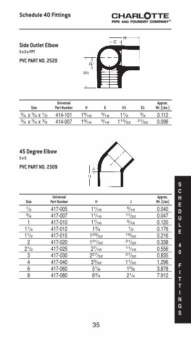
Side Outlet Elbow S x S x FPT
PVC PART NO. 2520
45 Degree ElbowS x S
PVC PART NO. 2309
Universal Approx. Size Part Number H J Wt. (Lbs)
1⁄2 417-005 11⁄16 5⁄16 0.040
3⁄4 417-007 11⁄16 11⁄32 0.047
1 417-010 17⁄16 5⁄16 0.120
11⁄4 417-012 13⁄4 1⁄2 0.176
11⁄2 417-015 129⁄32 19⁄32 0.216
2 417-020 131⁄32 21⁄32 0.338
21⁄2 417-025 27⁄16 11⁄16 0.556
3 417-030 227⁄32 27⁄32 0.835
4 417-040 33⁄32 11⁄32 1.296 6 417-060 51⁄8 15⁄8 3.878 8 417-080 63⁄4 21⁄4 7.912
Universal Approx. Size Part Number H G H1 G1 Wt. (Lbs.)
3⁄4 x 3⁄4 x 1⁄2 414-101 19⁄16 9⁄16 11⁄2
3⁄4 0.112 3⁄4 x 3⁄4 x 3⁄4 414-007 19⁄16
9⁄16 115⁄32 21⁄32 0.096
SCHEDULE
40
FITTINGS

36
Schedule 40 Fittings
Cross S x S x S x S
PVC PART NO. 2410
Universal Approx. Size Part Number L H G Wt. (Lbs)
1⁄2 420-005 29⁄16 19⁄32 17⁄32 0.080
3⁄4 420-007 35⁄16 121⁄32 21⁄32 0.152
1 420-010 37⁄8 115⁄16 13⁄16 0.222
11⁄4 420-012 41⁄2 21⁄4 1 0.372 11⁄2 420-015 47⁄8 27⁄16 11⁄8 0.450 2 420-020 51⁄2 23⁄4 13⁄8 0.678
Coupling S x S
PVC PART NO. 2100
Universal Approx. Size Part Number L N Wt. (Lbs)
1⁄2 429-005 17⁄8 1⁄8 0.028 3⁄4 429-007 111⁄16 3⁄32 0.038 1 429-010 23⁄32 3⁄32
0.067 11⁄4 429-012 25⁄8 1⁄8 0.136 11⁄2 429-015 23⁄4 1⁄8 0.116 2 429-020 27⁄8 1⁄8 0.165 21⁄2 429-025 325⁄32 3⁄16 0.444 3 429-030 41⁄32 3⁄16 0.786 4 429-040 43⁄4 3⁄16 0.966 6 429-060 69⁄32 9⁄32 2.218 8 429-080 811⁄32 1⁄4 4.370

37
Universal Approx. Size Part Number L N Wt. (Lbs)
1⁄2 430-005 15⁄8 7⁄32 0.039 3⁄4 430-007 13⁄4 11⁄32 0.052
Schedule 40 Fittings
Coupling FPT x FPT
PVC PART NO. 2102
Reducing Coupling S x S
PVC PART NO. 2100
Universal Approx. Size Part Number L N Wt. (Lbs)
3⁄4 x 1⁄2 429-101 17⁄8 1⁄8 0.052 1 x 3⁄4 429-131 21⁄4 1⁄8 0.080
SCHEDULE
40
FITTINGS
Riser Extension FPT x MPT
PVC PART NO. 2103
Universal Approx. Size Part Number L N T1 Wt. (Lbs)
1⁄2 x1⁄2 434-005 21⁄16 9⁄16 3⁄4 0.042

38
Schedule 40 Fittings
Universal Approx. Size Part Number L N Wt. (Lbs)
1⁄2 435-005 127⁄32 1⁄8 0.053 3⁄4 435-007 23⁄32 1⁄16 0.067 1 435-010 23⁄32 1⁄16 0.108 11⁄4 435-012 25⁄8 1⁄8 0.164 11⁄2 435-015 27⁄16 5⁄32 0.148 2 435-020 23⁄8 1⁄8 0.186 21⁄2 435-025 317⁄32 3⁄16 0.440 3 435-030 313⁄16 3⁄16 0.604 4 435-040 315⁄16 3⁄16 0.884
Female Adapter S x FPT
PVC PART NO. 2101
Universal Approx. Size Part Number L N T Wt. (Lbs)
1⁄2 x 3⁄4 435-074 125⁄32 3⁄32 1 0.053
Reducing Female Adapter S x FPT
PVC PART NO. 2104

39
Schedule 40 Fittings
Reducing Female Adapter S x FPT
PVC PART NO. 2101
Universal Approx. Size Part Number L N T Wt. (Lbs)
3⁄4 x 1⁄2 435-101 2 1⁄8 7⁄8 0.059
3⁄4 x 1 435-102 115⁄16 3⁄32 11⁄8 0.090 1 x 3⁄4 435-131 23⁄32 5⁄32
13⁄16 0.075
Universal Approx. Size Part Number L N T Wt. (Lbs)
1⁄2 436-005 119⁄32 5⁄32 11⁄16 0.029
3⁄4 436-007 15⁄8 5⁄32 23⁄32 0.037
1 436-010 23⁄16 3⁄16 7⁄8 0.080
11⁄4 436-012 27⁄16 3⁄16 1 0.122 11⁄2 436-015 27⁄16 3⁄16
15⁄16 0.144 2 436-020 221⁄32 7⁄32 11⁄32 0.234 21⁄2 436-025 319⁄32 7⁄32 15⁄8 0.388 3 436-030 37⁄8 7⁄32 115⁄32 0.546 4 436-040 331⁄32 1⁄4 111⁄16 0.820 6 436-060 53⁄4 21⁄32 19⁄16 2.114
Male Adapter MPT x S
PVC PART NO. 2109
SCHEDULE
40
FITTINGS
40
Schedule 40 Fittings
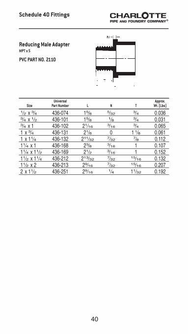
Reducing Male Adapter MPT x S
PVC PART NO. 2110
Universal Approx. Size Part Number L N T Wt. (Lbs)
1⁄2 x 3⁄4 436-074 15⁄8 5⁄32 3⁄4 0.036
3⁄4 x 1⁄2 436-101 15⁄8 1⁄8 3⁄4 0.031
3⁄4 x 1 436-102 21⁄16 3⁄16 3⁄4 0.065
1 x 3⁄4 436-131 21⁄8 0 1 1⁄8 0.061 1 x 11⁄4 436-132 211⁄32 7⁄32
7⁄8 0.112 11⁄4 x 1 436-168 23⁄8 3⁄16 1 0.107 11⁄4 x 11⁄2 436-169 21⁄2 3⁄16 1 0.152 11⁄2 x 11⁄4 436-212 213⁄32 7⁄32
15⁄16 0.132 11⁄2 x 2 436-213 29⁄16 7⁄32
15⁄16 0.207 2 x 11⁄2 436-251 29⁄16 1⁄4 11⁄32 0.192

41
Schedule 40 Fittings
Reducer Bushing, Flush Style SPG x S
PVC PART NO. 2107
Universal Approx. Size Part Number L SPG N Wt. (Lbs)
3⁄4 x 1⁄2 437-101 11⁄32 25⁄32
1⁄8 0.023 1 x 1⁄2 437-130 13⁄16
15⁄16 9⁄32 0.052
1 x 3⁄4 437-131 13⁄16 15⁄16
3⁄16 0.038 11⁄4 x 3⁄4 437-167 11⁄2 11⁄4
1⁄2 0.112 11⁄4 x 1 437-168 19⁄16 11⁄4
7⁄16 0.069 11⁄2 x 1⁄2 437-209 115⁄16 15⁄32
23⁄32 0.112 11⁄2 x 3⁄4 437-210 11⁄2 13⁄16
1⁄2 0.118 11⁄2 x 1 437-211 11⁄2 15⁄32
11⁄32 0.114 11⁄2 x 11⁄4 437-212 11⁄2 13⁄16
1⁄4 0.062 2 x 3⁄4 437-248 119⁄32 17⁄32
19⁄32 0.164 2 x 1 437-249 15⁄8 17⁄32
1⁄2 0.170 2 x 11⁄4 437-250 15⁄8 11⁄4
3⁄8 0.205 2 x 11⁄2 437-251 15⁄8 17⁄32
15⁄32 0.148 21⁄2 x 2 437-292 25⁄32 13⁄4
25⁄32 0.270 3 x 1 437-335 27⁄16 2 117⁄32 0.459 3 x 2 437-338 29⁄32 17⁄8
29⁄32 0.497 3 x 21⁄2 437-339 29⁄32 17⁄8
17⁄32 0.420 4 x 2 437-420 25⁄16 21⁄16
15⁄16 0.888 4 x 3 437-422 211⁄32 21⁄16
3⁄8 0.736 6 x 4 437-532 33⁄8 3 111⁄32 2.001 8 x 4 437-582 411⁄16 41⁄16 25⁄8 3.712 8 x 6 437-585 411⁄16 41⁄16 15⁄8 3.852
SCHEDULE
40
FITTINGS

42
Schedule 40 Fittings
Universal Approx. Size Part Number L SPG N Wt. (Lbs)
3⁄4 x 1⁄2 438-101 11⁄16 25⁄32 9⁄32 0.029
1 x 1⁄2 438-130 13⁄16 15⁄16 7⁄16 0.053
1 x 3⁄4 438-131 13⁄16 15⁄16 15⁄32 0.042
11⁄4 x 1⁄2 438-166 19⁄16 11⁄4 7⁄8 0.120
11⁄4 x 3⁄4 438-167 19⁄16 11⁄4 13⁄16 0.115
11⁄4 x 1 438-168 19⁄16 11⁄4 9⁄16 0.092
11⁄2 x 1⁄2 438-209 111⁄16 15⁄16 11⁄32 0.107 11⁄2 x 3⁄4 438-210 111⁄16 15⁄16
13⁄32 0.163 11⁄2 x 1 438-211 123⁄32 15⁄16
3⁄4 0.150 11⁄2 x 11⁄4 438-212 123⁄32 15⁄16
23⁄32 0.100 2 x 1⁄2 438-247 125⁄32 13⁄8 11⁄32 0.214 2 x 3⁄4 438-248 125⁄32 13⁄8
1 0.221 2 x 1 438-249 125⁄32 13⁄8
3⁄4 0.225 2 x 11⁄2 438-251 113⁄16 13⁄8
25⁄32 0.185 3 x 2 438-338 29⁄32 17⁄8 17⁄32 0.638 3 x 21⁄2 438-339 25⁄16 129⁄32
27⁄32 0.490 4 x 2 438-420 223⁄32 25⁄16 13⁄4 1.164 4 x 3 438-422 223⁄32 25⁄16 13⁄32 0.910 6 x 4 438-532 4 31⁄2 21⁄4 1.976
Reducer Bushing, Flush Style SPG x FPT
PVC PART NO. 2108

43
Reducer Bushing MPT x FPT
PVC PART NO. 2112
Schedule 40 Fittings
Universal Approx. Size Part Number L T N Wt. (Lbs)
3⁄4 x 1⁄2 439-101 1 3⁄4 1⁄4 0.022
1 x 1⁄2 439-130 11⁄4 3⁄4 1⁄2 0.059
1 x 3⁄4 439-131 11⁄4 3⁄4 1⁄2 0.043
11⁄4 x 3⁄4 439-167 15⁄16 3⁄4 9⁄16 0.092
11⁄4 x 1 439-168 15⁄16 1 5⁄16 0.063
11⁄2 x 3⁄4 439-210 13⁄8 23⁄32 21⁄32 0.128
11⁄2 x 1 439-211 13⁄8 1 11⁄32 0.110
11⁄2 x 11⁄4 439-212 13⁄8 1 3⁄8 0.068
2 x 11⁄2 439-251 17⁄16 1 7⁄16 0.143
Cap S
PVC PART NO. 2116
Universal Approx. Size Part Number L S Wt. (Lbs)
1⁄2 447-005 11⁄8 3⁄4 0.024 3⁄4 447-007 13⁄32 3⁄4 0.035 1 447-010 15⁄8 15⁄32 0.060 11⁄4 447-012 113⁄16 11⁄4 0.094 11⁄2 447-015 13⁄4 11⁄8 0.116 2 447-020 25⁄32 113⁄32 0.184 21⁄2 447-025 217⁄32 113⁄16 0.368 3 447-030 215⁄16 129⁄32 0.463 4 447-040 31⁄8 21⁄32 0.720 6 447-060 41⁄2 31⁄32 2.349 8 447-080 63⁄16 4 4.074
SCHEDULE
40
FITTINGS

44
Schedule 40 Fittings
Universal Approx. Size Part Number L T Wt. (Lbs)
1⁄2 448-005 11⁄8 7⁄8 0.033 3⁄4 448-007 11⁄4 1 0.046 1 448-010 19⁄32 15⁄16 0.068 11⁄4 448-012 17⁄16 1 0.108 11⁄2 448-015 19⁄16 1 0.140 2 448-020 15⁄8 11⁄16 0.192
Cap FPT
PVC PART NO. 2117
Plug SPG
PVC PART NO. 2118
Universal Approx. Size Part Number L SPG Wt. (Lbs)
1⁄2 449-005 29⁄32 11⁄16 0.017 3⁄4 449-007 1 3⁄4 0.028 1 449-010 15⁄32 7⁄8 0.047 11⁄2 449-015 11⁄2 13⁄16 0.102 2 449-020 15⁄8 11⁄4 0.152

45
Schedule 40 Fittings
Plug MPT
PVC PART NO. 2113
Universal Approx. Size Part Number L T Wt. (Lbs)
1⁄2 450-005 15⁄16 3⁄4 0.017 3⁄4 450-007 1 3⁄4 0.028 1 450-010 11⁄4 1 0.050 11⁄4 450-012 15⁄16 1 0.074 11⁄2 450-015 15⁄16 1 0.102 2 450-020 115⁄32 11⁄16 0.184
SCHEDULE
40
FITTINGS
HVAC Condensate P Trap(D) SPG x SPG
PVC PART NO. 2700
Universal Approx. Size Part Number A B Wt. (Lbs)
3⁄4 489-007 7 3⁄4 2 7⁄8 0.193
HVAC Condensate Running Trap (D) SPG x SPG
PVC PART NO. 2701
Universal Approx. Size Part Number A Wt. (Lbs)
1⁄2 (C) 488-005 105⁄16 0.145 3⁄4 488-007 107⁄16 0.193
A
B
A
(D) Does not conform to ASTM D 2466.(C) Contact sales office for availability.

46
Pipe Data
CTS 12005 1⁄2” x 10’ 04979 12,000’ .625 .068 400 PSI 8.3 CTS 12005 1⁄2” x 20’ 04993 24,000’ .625 .068 400 PSI 8.3 CTS 12007 3⁄4” x 10’ 04980 6,000’ .875 .080 400 PSI 13.9 CTS 12007 3⁄4” x 20’ 05145 12,000’ .875 .080 400 PSI 13.9 CTS 12010 1” x 10’ 05146 3,600’ 1.125 .102 400 PSI 22.2 CTS 12010 1” x 20’ 05147 7,200’ 1.125 .102 400 PSI 22.2 CTS 12012 11⁄4” x 10’ 05148 2,400’ 1.375 .125 400 PSI 33.3 CTS 12012 11⁄4” x 20’ 05321 4,800’ 1.375 .125 400 PSI 33.3 CTS 12015 11⁄2” x 10’ 05150 1,440’ 1.625 .148 400 PSI 46.6 CTS 12015 11⁄2” x 20’ 05306 2,880’ 1.625 .148 400 PSI 46.6 CTS 12020 2” x 10’ 05152 960’ 2.125 .193 400 PSI 79.5 CTS 12020 2” x 20’ 05322 1,920’ 2.125 .193 400 PSI 79.5
CPVC Copper Tube Size Pipe
PVC SCHEDULE 40 (WHITE) PLAIN END PVC 1120 ASTM D 2665
FlowGuard Gold® Pipe
STRAIGHT LENGTHS PLAIN END SDR 11 CPVC COPPER TUBE SIZE PIPE ASTM D 2846 MAX WORK WT. PER PART NO. NOM. SIZE UPC # QTY. PER AVG. OD MIN. WALL PRESSURE 100 FT. 611942- SKID (IN.) (IN.) AT 23°C OR 73°F (LBS.)
FlowGuard Gold is a registered trademark of The Lubrizol Corporation.
MADE INU.S.A.
NSF Listed. Meets All Requirements of ASTM D 2846.
CTS 12005 1⁄2”x150’ 05313 3,750’ .625 .068 400 PSI 8.3 CTS 12007 3⁄4”x100’ 05314 2,500’ .875 .080 400 PSI 13.9 CTS 12010 1”x100’ 10643 1,200’ 1.125 .102 400 PSI 22.2
PVC SCHEDULE 40 (WHITE) PLAIN END PVC 1120 ASTM D 2665 COILED PIPE SDR 11 COILED SDR CPVC COPPER TUBE SIZE PIPE ASTM D 2846 MAX WORK WT. PER PART NO. NOM. SIZE UPC # QTY. PER AVG. OD MIN. WALL PRESSURE 100 FT. 611942- SKID (IN.) (IN.) AT 23°C OR 73°F (LBS.)
NOTE: STRAIGHT LENGTH PIPE ARE SHIPPED IN FULL BUNDLE QUANTITY ONLY.
Testing with or use of compressed air or gas in PVC / ABS / CPVC pipe or fittings can result in explosive failures and cause severe injury or death.
• NEVER test with or transport/store compressed air or gas in PVC / ABS / CPVC pipe or fittings.
• NEVER test PVC / ABS / CPVC pipe or fittings with compressed air or gas, or air over water boosters.
• ONLY use PVC / ABS / CPVC pipe or fittings for water or approved chemicals.
• Refer to warnings on PPFA’s website and ASTM D 1785.

47
1⁄2 0.633 (16.08) 0.500 (12.70) 3⁄4 0.884 (22.45) 0.700 (17.78) 1 1.135 (28.83) 0.900 (22.86) 11⁄4 1.386 (35.20) 1.100 (27.94) 11⁄2 1.640 (41.66) 1.300 (33.02) 2 2.141 (54.38) 1.700 (43.18)
1⁄2 0.382 (9.70) 0.183 (4.65) 0.102 (2.59) 3⁄4 0.507 (12.88) 0.235 (5.97) 0.102 (2.59) 1 0.633 (16.08) 0.287 (7.29) 0.102 (2.59) 11⁄4 0.758 (19.25) 0.339 (8.61) 0.102 (2.59) 11⁄2 0.884 (22.45) 0.391 (9.93) 0.102 (2.59) 2 1.134 (28.83) 0.495 (12.57) 0.102 (2.59)
NOMINAL “G” MINIMUM “J” MINIMUM “N” MINIMUM SIZE (IN.) IN. (mm) IN. (mm) IN. (mm)
TAPERED SOCKET DIMENSIONS FOR CPVC 41,SDR 11 PLASTIC PIPE FITTINGS
NOMINALSIZE (IN.)
SOCKET ENTRANCE DIAMETER, IN. (mm) SOCKET LENGTH, IN. (mm) “A” AVERAGE “C” MINIMUM
MINIMUM DIMENSIONS FROM CENTER TO END OF SOCKET(LAYING LENGTH) FOR CPVC 41, SDR 11 FITTINGS
FlowGuard Gold® Fittings
FLOWGUARD
GOLD

48
FlowGuard Gold® CPVC CTS Fittings
Coupling S x S
CTS PART NO. 2100
UPC# Approx. Size 611942- L N Wt. (Lbs) 1⁄2 04994 11⁄8 1⁄8 0.016 3⁄4 05154 11⁄2 1⁄8 0.027 1 05155 115⁄16 1⁄8 0.050 11⁄4 05156 211⁄32 1⁄8 0.085 11⁄2 05157 211⁄16 1⁄8 0.134 2 05158 317⁄32 1⁄8 0.300
Coupling S x S
CTS PART NO. 2100
UPC# Approx. Size 611942- L N Wt. (Lbs) 3⁄4 x 1⁄2 05159 113⁄32 3⁄16 0.02 1 x 3⁄4 05160 113⁄16 3⁄16 0.04 11⁄4 x 1(A) 09942 21⁄2 9⁄16 0.12(A) Assembled

49
FlowGuard Gold® CPVC CTS Fittings
Transition Coupling IPS S x CTS S
CTS PART NO. 2100I
UPC# Approx. Size 611942- L N Wt. (Lbs) 3⁄4 04996 15⁄8 3⁄16 0.50 1 05175 21⁄8 1⁄8 0.07
Reducer Bushing SPG x S
CTS PART NO. 2107
UPC# Approx. Size 611942- L N Wt. (Lbs) 3⁄4 x 1⁄2 04998 27⁄32 11⁄32 0.010 1 x 1⁄2 05177 11⁄32 17⁄32 0.030 1 x 3⁄4 05178 11⁄32 5⁄16 0.020 11⁄4 x 1⁄2 05179 11⁄4 3⁄4 0.050 11⁄4 x 3⁄4 05180 17⁄32 1⁄2 0.060 11⁄4 x 1 05181 11⁄4 11⁄32 0.040 11⁄2 x 1⁄2 05182 17⁄16 15⁄16 0.080 11⁄2 x 3⁄4 05183 17⁄16 23⁄32 0.080 11⁄2 x 1 05184 17⁄16 17⁄32 0.083 11⁄2 x 11⁄4 05185 17⁄16 5⁄16 0.050 2 x 1⁄2 05186 113⁄16 15⁄16 0.170 2 x 3⁄4 05187 113⁄16 13⁄32 0.170 2 x 1 05188 113⁄16 7⁄16 0.180 2 x 11⁄4 05189 113⁄16 11⁄16 0.160 2 x 11⁄2 05190 113⁄16 1⁄2 0.150
FLOWGUARD
GOLD

50
FlowGuard Gold® CPVC CTS Fittings
Transition Bushing IPS SPG X CTS S
CTS PART NO. 2107I
UPC# Approx. Size 611942- L N Wt. (Lbs) 1⁄2 04999 11⁄32 17⁄32 0.01 3⁄4 05191 11⁄8 13⁄32 0.02 1 05192 19⁄32 3⁄8 0.03 11⁄4 05193 13⁄8 11⁄32 0.06 11⁄2 05194 11⁄2 3⁄16 0.07 2 05195 17⁄8 5⁄32 0.10
Male Adapter S x MPT
CTS PART NO. 2109**
UPC# Approx. Size 611942- L N Wt. (Lbs) 1⁄2 05000 15⁄16 1⁄8 0.02 3⁄4 05196 15⁄8 3⁄32 0.04 1 05197 131⁄32 1⁄8 0.07 11⁄4 05198 215⁄32 1⁄4 0.12 11⁄2 05199 27⁄8 9⁄32 0.18 2 05200 35⁄8 7⁄32 0.34
** For cold water applications only. Does not conform to the requirements of ASTM D 2846.

51
FlowGuard Gold® CPVC CTS Fittings
Reducing Male Adapter S x MPT
CTS PART NO. 2110**
UPC# Approx. Size 611942- L N Wt. (Lbs) 3⁄4 x 1⁄2 05252 13⁄4 5⁄32 0.040
** For cold water applications only. Does not conform to the requirements of ASTM D 2846.
Cap S
CTS PART NO. 2116
UPC# Approx. Size 611942- L S Wt. (Lbs) 1⁄2 05002 3⁄4 1⁄2 0.01 3⁄4 05202 1 23⁄32 0.02 1 05203 11⁄8 29⁄32 0.04 11⁄4 05204 19⁄16 11⁄8 0.06 11⁄2 05205 123⁄32 15⁄16 0.10 2 05206 21⁄16 123⁄32 0.21
FLOWGUARD
GOLD

52
FlowGuard Gold® CPVC CTS Fittings
90 Degree Elbow S x S
CTS PART NO. 2300
UPC# Approx. Size 611942- H G G1 H1 Wt. (Lbs) 1⁄2 04982 7⁄8 3⁄8 0.025 3⁄4 04983 11⁄4 9⁄16 0.049 1 04984 117⁄32 5⁄8 0.073 11⁄4 05006 127⁄32 3⁄4 0.135 11⁄2 05207 23⁄16 7⁄8 0.213 2 05208 227⁄32 15⁄32 0.456
90 Degree Elbow, Reducing S x S
CTS PART NO. 2300
UPC# Approx. Size 611942- G G1 H H1 Wt. (Lbs) 3⁄4 x 1⁄2 05209 13⁄32 17⁄32 11⁄8 11⁄32 0.037

53
FlowGuard Gold® CPVC CTS Fittings
Drop Ear Elbow All CPVC - S x S
CTS PART NO. 2300D
UPC# Approx. Size 611942- H G Wt. (Lbs) 1⁄2 05007 29⁄32 3⁄8 0.03
90 Degree Street Elbow SPG x S
CTS PART NO. 2304
UPC# Approx. Size 611942- H G H1 G1 Wt. (Lbs) 1⁄2 05011 11⁄32 17⁄32 7⁄8 3⁄8 0.03 3⁄4 04985 113⁄32 11⁄16 117⁄32 13⁄16 0.05 1 09922 123⁄32 13⁄16 117⁄32 5⁄8 0.08 11⁄4 08162 27⁄16 29⁄32 215⁄32 17⁄32 0.23
FLOWGUARD
GOLD

54
FlowGuard Gold® CPVC CTS Fittings
45 Degree Elbow S x S
CTS PART NO. 2309
UPC# Approx. Size 611942- H J Wt. (Lbs) 1⁄2 05012 11⁄16 3⁄16 0.020 3⁄4 05228 15⁄16 1⁄4 0.039 1 05229 13⁄16 9⁄32 0.059 11⁄4 05230 17⁄16 11⁄32 0.109 11⁄2 05231 111⁄16 3⁄8 0.174 2 05232 23⁄16 1⁄2 0.373
Street Elbow 45 Degree SPG x S
CTS PART NO. 2310
UPC# Approx. Size 611942- H J Wt. (Lbs) 1⁄2 05013 11⁄16 3⁄16 0.02 3⁄4 05233 15⁄16 1⁄4 0.03 1 10652 17⁄32 5⁄16 0.06

55
FlowGuard Gold® CPVC CTS Fittings
Tee S x S x S
CTS PART NO. 2400
UPC# Approx. Size 611942- L H G Wt. (Lbs) 1⁄2 05014 113⁄16 29⁄32 13⁄32 0.032 3⁄4 05238 27⁄16 17⁄32 1⁄2 0.059 1 05239 31⁄16 117⁄32 5⁄8 0.104 11⁄4 05240 33⁄4 17⁄8 25⁄32 0.177 11⁄2 05241 43⁄8 23⁄16 7⁄8 0.286 2 05242 511⁄16 227⁄32 11⁄8 0.624
FLOWGUARD
GOLD

56
FlowGuard Gold® CPVC CTS Fittings
Reducer Tee S x S x S
CTS PART NO. 2400
UPC# Approx. Size 611942- L H G H1 G1 Wt. (Lbs) 1⁄2 x 1⁄2 x 3⁄4 10685 21⁄16 11⁄32 1⁄2 11⁄4 17⁄32 0.04 3⁄4 x 3⁄4 x 1⁄2 05243 27⁄16 17⁄32 1⁄2 11⁄32 1⁄2 0.05 3⁄4 x 3⁄4 x 1 05019 33⁄8 111⁄16 5⁄8 117⁄32 5⁄8 0.15 3⁄4 x 1⁄2 x 1⁄2 05244 27⁄32 17⁄32 1⁄2 11⁄32 1⁄2 0.05 3⁄4 x 1⁄2 x 3⁄4 05245 21⁄4 17⁄32 1⁄2 17⁄32 1⁄2 0.06 1x1⁄2x1⁄2 05020 37⁄32 117⁄32 5⁄8 111⁄16 13⁄16 0.17 1 x 1⁄2 x 3⁄4 05021 37⁄32 117⁄32 5⁄8 111⁄16 13⁄16 0.16 1 x 1⁄2 x 1 05022 37⁄32 117⁄32 5⁄8 117⁄32 5⁄8 0.13 1 x 3⁄4 x 1⁄2 05023 37⁄32 117⁄32 5⁄8 111⁄16 31⁄32 0.16 1 x 3⁄4 x 3⁄4 10598 225⁄32 17⁄16 17⁄32 111⁄32 5⁄8 0.08 1 x 3⁄4 x 1 05025 231⁄32 119⁄32 11⁄16 19⁄16 21⁄32 0.11 1 x 1 x 1⁄2 10599 25⁄8 15⁄16 11⁄32 129⁄32 17⁄32 0.08 1 x 1 x 3⁄4 05469 215⁄16 115⁄32 9⁄16 13⁄8 21⁄32 0.09 11⁄4 x 1 x 1 05038 37⁄8 17⁄8 3⁄4 2 13⁄32 0.15 11⁄4 x 11⁄4 x 1⁄2 11262 3 11⁄2 3⁄8 19⁄32 3⁄4 0.12 11⁄4 x 11⁄4 x 3⁄4 11192 33⁄16 119⁄32 15⁄32 11⁄2 25⁄32 0.13 11⁄4 x 11⁄4 x 1 11233 31⁄2 13⁄4 5⁄8 111⁄16 25⁄32 0.15 11⁄2 x 1 x 1 05056 41⁄2 21⁄4 15⁄16 211⁄32 11⁄2 0.21 11⁄2 x 11⁄2 x 1⁄2 11592 37⁄8 115⁄16 5⁄8 111⁄32 13⁄16 0.21 11⁄2 x 11⁄2 x 3⁄4 11232 37⁄8 115⁄16 5⁄8 121⁄32 15⁄16 0.21 11⁄2 x 11⁄2 x 1 10686 37⁄8 115⁄16 5⁄8 123⁄32 25⁄32 0.21 2 x 2 x 1⁄2 11234 43⁄16 23⁄32 3⁄8 15⁄8 13⁄32 0.35 2 x 2 x 3⁄4 11235 47⁄16 27⁄32 1⁄2 17⁄8 15⁄32 0.37 2 x 2 x 1 10687 411⁄16 211⁄32 5⁄8 131⁄32 11⁄16 0.41 2 x 2 x 11⁄2 11236 53⁄8 211⁄16 31⁄32 27⁄16 11⁄8 0.51

57
FlowGuard Gold® CPVC CTS Fittings
Low-Lead Female Adapter, Brass Threads BRASS FPT X CTS HUB
CTS PART NO. 2105L
UPC# Approx. Size 611942- L T Wt. (Lbs) 1⁄2 11632 111⁄16 5⁄8 0.17 3⁄4 11634 131⁄32 5⁄8 0.22 1 11635 29⁄16 5⁄8 0.48 11⁄4 12404 31⁄16 3⁄4 0.88 11⁄2 12405 39⁄32 7⁄8 1.07 2 12406 311⁄16 31⁄32 1.48
Low-Lead Male Adapter, Brass Threads BRASS MPT X CTS HUB
CTS PART NO. 2115L
UPC# Approx. Size 611942- L T Wt. (Lbs) 1⁄2 11636 17⁄8 1⁄2 0.17 3⁄4 11637 21⁄8 1⁄2 0.20 1 11638 23⁄4 3⁄4 0.39 11⁄4 12407 33⁄16 25⁄32 0.83 11⁄2 12408 31⁄2 13⁄16 1.12 2 12409 41⁄32 13⁄16 1.85
FLOWGUARD
GOLD

58
FlowGuard Gold® CPVC CTS Fittings
Low-Lead CPVC/Brass Drop Ear Elbow 90 Degree BRASS FPT X CPVC HUB
CTS PART NO. 2302L
UPC# Approx. Size 611942- H H1 G G1 Wt. (Lbs) 1⁄2 11640 29⁄32 13⁄4 13⁄32 17⁄32 0.28

59
Certification
This is to certify that all Plastic Pipe and Fittings manufactured by Charlotte Pipe and Foundry Company are manufactured in the United States and conform to the following standards:
PVC SCH. 40 SOLID WALL PIPEASTM D 1784, ASTM D 1785, ASTM D 2665FHA UM 79aFEDERAL SPECIFICATION L-P-320aNSF STANDARD NO. 14 AND 61
PVC SCH. 40 DWV CELLULAR CORE PIPEASTM D 4396, ASTM F 891NSF STANDARD NO. 14
PVC SCH. 40 DWV FITTINGSASTM D 1784, ASTM D 2665, ASTM D 3311, ASTM F 1866FHA UM 79aFEDERAL SPECIFICATION L-P-320aNSF STANDARD NO. 14
PVC SDR-21 AND SDR-26 PRESSURE PIPEASTM D 1784, ASTM D 2241NSF STANDARD NO. 14 AND 61
PVC SCH. 40 PRESSURE FITTINGSASTM D 1784, ASTM D 2466NSF STANDARD NO. 14 AND 61
PVC SCH. 40 WELL CASING PIPEASTM D 1784, ASTM F 480NSF STANDARD NO. 14 AND 61
PVC SCH. 80 PIPEASTM D 1784, ASTM D 1785, PVC 1120NSF STANDARD NO. 14 AND 61
PVC SCH. 80 FITTINGSASTM D 1784, ASTM D 2467, ASTM D 2464, ASTM F 1970NSF STANDARD NO. 14 AND 61
CERTIFICATION

60
Certification
PVC SDR 35 SEWER MAIN PIPEASTM D 1784, ASTM D 3034 SDR 35ASTM D 3212, ASTM F 477
PVC SEWER AND DRAIN PIPEASTM D 1784, ASTM D 2729
PVC THIN WALL PIPE & FITTINGSASTM D 1784, ASTM D 2949NSF STANDARD NO. 14
CPVC FLOWGUARD GOLD® CTS PIPE & FITTINGSASTM D 1784, ASTM D 2846FHA UM-61aNSF STANDARD NO. 14. AND 61 CSA LISTED ON SPECIFIED ITEMS
CPVC CHEMDRAIN® SCH. 40 PIPE & FITTINGSASTM D 1784, ASTM F 2618NSF STANDARD NO. 14
ABS SCH. 40 DWV CELLULAR CORE PIPEASTM D 3965, ASTM F 628NSF STANDARD NO. 14
ABS PLUS® SCH. 40 DWV CELLULAR CORE PIPEASTM D 3965, ASTM D 4396, ASTM F 1488NSF STANDARD NO. 14.
ABS SCH. 40 DWV FITTINGSASTM D 3965, ASTM D 2661, ASTM D 3311FHA UM 79aFEDERAL SPECIFICATION L-P-322bNSF STANDARD NO. 14
MADE INU.S.A.

61
LIMITED WARRANTY
Charlotte and Charlotte Pipe are registered trademarks of Charlotte Pipe and Foundry Company.
Charlotte Pipe and Foundry Company® (Charlotte Pipe®) Products are warranted to be free from manufacturing defects and to conform to currently applicable ASTM standards for a period of five (5) years from date of delivery. Buyer’s remedy for breach of this warranty is limited to replacement of, or credit for, the defective product. This warranty excludes any expense for removal or reinstallation of any defective product and any other incidental, consequential, or punitive damages. This limited warranty is the only warranty made by seller and is expressly in lieu of all other warranties, express and implied, including any warranties of merchantability and fitness for a particular purpose. No statement, conduct or description by Charlotte Pipe or its representative, in addition to or beyond this Limited Warranty, shall constitute a warranty. This Limited Warranty may only be modified in writing signed by an officer of Charlotte Pipe.This Limited Warranty will not apply if:1) The Products are used for purposes other than their intended purpose as defined by local
plumbing and building codes, and the applicable ASTM standard.2) The Products are not installed in good and workmanlike manner consistent with normal
industry standards; installed in compliance with the latest instructions published by Charlotte Pipe and good plumbing practices; and installed in conformance with all applicable plumbing, fire and building code requirements.
3) This limited warranty does not apply when the products of Charlotte Pipe are used with the products of other manufacturers that do not meet the applicable ASTM or CISPI standards or that are not marked in a manner to indicate the entity that manufactured them.
4) In hubless cast iron installations, this warranty will not apply if products are joined with unshielded hubless couplings. Charlotte Pipe requires that its hubless cast iron pipe and fittings be joined only with shielded hubless couplings manufactured in accordance with CISPI 310, ASTM C 1277 and certified by NSF® International or with Heavy Duty Couplings meeting ASTM C 1540.
5) The Products fail due to defects or deficiencies in design, engineering, or installation of the piping system of which they are a part.
6) The Products have been the subject of modification; misuse; misapplication; improper maintenance or repair; damage caused by the fault or negligence of anyone other than Charlotte Pipe; or any other act or event beyond the control of Charlotte Pipe.
7) The Products fail due to the freezing of water in the Products.8) The Products fail due to contact with chemical agents, fire stopping materials, thread sealant,
plasticized vinyl products, or other aggressive chemical agents that are not compatible.9) Pipe outlets, sound attenuation systems or other devices are permanently attached to the
surface of Charlotte® PVC, ABS or CPVC products with solvent cement or adhesive glue.Charlotte Pipe products are manufactured to the applicable ASTM or CISPI standard. Charlotte Pipe and Foundry cannot accept responsibility for the performance, dimensional accuracy, or compatibility of pipe, fittings, gaskets, or couplings not manufactured or sold by Charlotte Pipe and Foundry. Any Charlotte Pipe products alleged to be defective must be made available to Charlotte Pipe at the following address for verification, inspection and determination of cause:
Charlotte Pipe and Foundry CompanyAttention: Technical Services
2109 Randolph RoadCharlotte, North Carolina 28207
Purchaser must obtain a return materials authorization and instructions for return shipment to Charlotte Pipe of any product claimed defective or shipped in error.Any Charlotte Pipe product proved to be defective in manufacture will be replaced F.O.B. point of original delivery, or credit will be issued, at the discretion of Charlotte Pipe. 4/24/15
Testing with or use of compressed air or gas in PVC / ABS / CPVC / Cast Iron pipe or fittings can result in explosive failures and cause severe injury or death.
• NEVER test with or transport/store compressed air or gas in PVC / ABS / CPVC / Cast Iron pipe or fittings.
• NEVER test PVC / ABS / CPVC / Cast Iron pipe or fittings with compressed air or gas, or air over water boosters.
• ONLY use PVC / ABS / CPVC / Cast Iron pipe or fittings for water or approved chemicals.
• Refer to warnings on PPFA’s website and ASTM D 1785.
LIMITED
WARRANTY

62
Charlotte Pipe and Foundry Company (Charlotte Pipe®) warrants to the original owner of the structure in which its FlowGuard Gold CTS CPVC Pipe and Fittings (the “Products”) have been installed, that the Products will be free from manufacturing defects and conform to currently applicable ASTM standards under normal use and service for a period of ten (10) years. Buyer’s remedy for breach of this warranty is limited to replacement of, or credit for, the defective product. This warranty excludes any expense for removal or reinstallation of any defective product and any other incidental, consequential, or punitive damages. This limited warranty is the only warranty made by seller and is expressly in lieu of all other warranties, express and implied, including any warranties of merchantability and fitness for a particular purpose. No statement, conduct or description by Charlotte Pipe or its representative, in addition to or beyond this Limited Warranty, shall constitute a warranty. This Limited Warranty may only be modified in writing signed by an officer of Charlotte Pipe.This Limited Warranty will not apply if:1) The Products are used for purposes other than the transmission of domestic water.2) The Products are not installed in good and workmanlike manner consistent with normal
industry standards; installed in compliance with the latest instructions published by Charlotte Pipe and good plumbing practices; and installed in conformance with all applicable plumbing, fire and building code requirements.
3) This limited warranty does not apply when the products of Charlotte Pipe are used with the products of other manufacturers that do not meet the ASTM standard or that are not marked in a manner to indicate the entity that manufactured them.
4) The Products fail due to defects or deficiencies in design, engineering, or installation of the water distribution system of which they are a part.
5) The Products have been the subject of modification; misuse; misapplication; improper maintenance or repair; damage caused by the fault or negligence of anyone other than Charlotte Pipe; or any other act or event beyond the control of Charlotte Pipe.
6) The Products fail due to the freezing of water in the Products.7) The Products fail due to contact with chemical agents, fire stopping materials, thread
sealant, plasticized vinyl products, or other aggressive chemical agents not compatible with CPVC compounds.
Charlotte Pipe products are manufactured to the applicable ASTM standard. Charlotte Pipe and Foundry cannot accept responsibility for the performance, dimensional accuracy, or compatibility of pipe, fittings, gaskets, or couplings not manufactured or sold by Charlotte Pipe and Foundry. Any Charlotte Pipe products alleged to be defective must be made available to Charlotte Pipe at the following address for verification, inspection and determination of cause:
Charlotte Pipe and Foundry CompanyAttention: Technical Services
2109 Randolph RoadCharlotte, North Carolina 28207
Purchaser must obtain a return materials authorization and instructions for return shipment to Charlotte Pipe of any product claimed defective or shipped in error. Any Charlotte Pipe product proved to be defective in manufacture will be replaced F.O.B. point of original delivery, or credit will be issued, at the discretion of Charlotte Pipe.
3/25/10
FlowGuard Gold® CPVC CTS Limited Warranty
Charlotte Pipe is a registered trademark of Charlotte Pipe and Foundry Company.FlowGuard Gold is a registered trademark of Lubrizol Corporation.
Testing with or use of compressed air or gas in PVC / ABS / CPVC pipe or fittings can result in explosive failures and cause severe injury or death.
• NEVER test with or transport/store compressed air or gas in PVC / ABS / CPVC pipe or fittings.
• NEVER test PVC / ABS / CPVC pipe or fittings with compressed air or gas, or air over water boosters.
• ONLY use PVC / ABS / CPVC pipe or fittings for water or approved chemicals.
• Refer to warnings on PPFA’s website and ASTM D 1785.

63
Notes

PO BOX 35430
CHARLOTTE
NORTH CAROLINA 28235
PHONE (704) 348-6450
(800) 438-6091
FAX (800) 553-1605
WWW.CHARLOTTEPIPE.COM