pw/pwe 085 - 096rdl-hydraulics.com/wp-content/uploads/2013/10/poclain-pompy-pw-p… · pw/pwe 085 -...
TRANSCRIPT

H E A V Y -D U TY H Y D R O S TA TIC P U M P
T E C H N I C A L C A T A L O G
P W /P W E 085 - 096

2 27/11/2015
Heavy-duty pump PW/PWe 085 - 096 POCLAIN HYDRAULICS
OVERVIEWPWe085/PWe096 is a compact unit able to be directy mounted on the main internal combustion engine, LPG or Diesel, or on a power take-off.
Variable displacement, axial piston pump, with swashplate system, for closed loop hydrostatic transmissions.
It provides a continuously variable flow rate between zero and maximum in forward and reverse direction. Flow rate is proportional to rotation speed and swashplate angle.
It is featured with a charge pump to keep the circuit pressurised. This avoids risk of cavitations and ensures a good performance of the transmission.
It is equipped with high pressure relief valves and control pressure cut-off valve.
It is available in single or tandem version.
As options PWe085/PWe096 can be featured with exchange valve, filter on charge pressure line and safety devices to ensure safe operation of the machine.
PW/PWe085 PW/PWe096
Displacement cm³/rev[in³/rev.]
85,2[5.20]
96,4 [5.88]
Theoretical Flow at rated speed
L/min[GPM]
170[44.91]
192[50.72]
Mass moment of inertia of rotating components
kg.m2
[slug.ft2]0,0127
[0.0091]0,0125
[0.0089]Pump torqueat vg max and p
Nm [in.lbf]p = bar [PSI]
582 [5151]p = 430 [6237]
580 [5133]p = 380 [5511]
Theoretical Power kW [hp] 223 [299]
at vg max, max. continuous speed and p p = bar [PSI] p = 430 [6237] p = 380 [5511]
Mounting flange SAE - C
Control Solenoid control with feedback sensor and control pressure cut-off valve
Mass kg [lb] 71 [157]
Rotation Clockwise or Counterclockwise

27/11/2015 3
POCLAIN HYDRAULICS Heavy-duty pump PW/PWe 085 - 096
Syst
em d
esig
n Pa
ram
eter
sM
odel
Cod
eO
pera
ting
Para
met
ers
Tech
nica
l sp
ecifi
catio
nsFe
atur
esO
ptio
nsC
ontr
ols
PWe
inst
alla
tion
PWe
pack
age
desc
riptio
n
The PW & PWe range: Productivity, Comfort and Energy Efficiency
Used in hydrostatic transmission systems composed of motors, valves, and electronic controls, the PW & PWe range offers you the benefit of over 50 years of expertise gained by Poclain Hydraulics in the field of hydrostatic transmissions.
The performance and added value they provide will help make your machines a commercial success.
The upcoming anti-pollution standards impose new constraints which must be taken into consideration. End users look for reliable, precise, high performance machines that minimize energy expenditure and maximize comfort.
Designed with compactness, energy efficiency and high power density in mind, the “Heavy Duty” PW & PWe pump range meets these requirements.

4 27/11/2015
Heavy-duty pump PW/PWe 085 - 096 POCLAIN HYDRAULICS
PWE INSTALLATION 33PWe ECU description 33PWe ECU characteristics 34PWe ECU environmental performances 35PWe ECU input characteristics 35PWe ECU output characteristics 36Wiring 37Pump command interface 40Auxiliaries 43PWe ECU Configurator 45Description of functions 48
PWE PACKAGE DESCRIPTION 53Definitions 53List of functions 53Anti-stall 54Brake lights 54Driver presence 55Temperature protection 55Over pressure protection 56Over power protection 56Engine over speed protection 57Diagnostic 57Command device 58Start-up check 59Hill start 60Proportional engine control 60Fixed engine control 61Mixed engine control 62CAN broadcasting 63Braking/Inching 68Speed control loop 69CAN slave management 70Details of CAN messages 71

POCLAIN HYDRAULICS Heavy-duty pump PW/PWe 085 - 096
27/11/2015 5
CONTENT
Syst
em d
esig
n Pa
ram
eter
sM
odel
Cod
eO
pera
ting
Para
met
ers
Tech
nica
l sp
ecifi
catio
nsFe
atur
esO
ptio
nsC
ontr
ols
PWe
inst
alla
tion
PWe
pack
age
desc
riptio
n
MODEL CODE 6
TECHNICAL SPECIFICATIONS 9Main dimensions for PW 9Port characteristics 9Main dimensions for PWe 10Port characteristics 10
OPERATING PARAMETERS 11Operating parameters 11Charge pressure 11Case pressure 11Pressure ratings 11Speed ratings 11Poclain Hydraulics recommandations for fluid 12Theoretical output 12Viscosity range 13Fluid and filtration 13
SYSTEM DESIGN PARAMETERS 15Sizing equations 15Redundant braking system requirement 15Reservoir 15Case drain usage for tandem pump 15Bearing life and external shaft loading 16Mounting flange loads 17Hydraulic unit life 17Tandem pumps 18
FEATURES 19High pressure relief valves 19Charge pressure relief valve 20Charge pump 21Filtration 22Mounting flange and shafts 25Auxiliary mounting pad 26
CONTROLS 29Solenoid control with feedback sensor and cut-off valve 29
OPTIONS 75Installed speed sensor or predisposition 75Bypass of orifices in SA control 77Without control pressure cut-off valve 78Special paint or no paint 78Exchange valve 792 bolt bearing flange mounting 80Pressure sensors on A&B lines 80Temperature sensor 82

Heavy-duty pump PW/PWe 085 - 096 POCLAIN HYDRAULICS
6 27/11/2015
MODELSize D
* Not recommended for front pump in tandem configuration.
MMounting flange and shaftSAE-C; splined shaft; z = 21; 16/32 D.P. 2SAE-C; splined shaft; z = 23; 16/32 D.P. 3SAE-C; splined shaft; z = 13; 8/16 D.P. 5SAE-C; splined shaft; z = 14; 12/24 D.P. * 6
CControlsSolenoid control 12 Vwith feedback sensor and control pressure cut-off valve A
Solenoid control 24 Vwith feedback sensor and control pressure cut-off valve B
SizeDisplacement cm3/rev [in3/rev]85,2 [5.20] 08596,4 [5.88] 096
M C O
W eH1
DDirection of rotationClockwise (CW) RCounterclockwise (CCW) L
OPorts mm [inch](P) inlet (S1) servo (S2) servo (T)
w/o w/o w/o N/A 00,8 [0.031] 0,8 [0.031] 0,8 [0.031] N/A 1
w/o 1,5 [0.059] 1,5 [0.059] N/A 2w/o 0,8 [0.031] 0,8 [0.031] N/A 3
H1High pressure relief valve (A) **bar (± 15) [PSI (± 218)] 320 [4641] A350 [5076] B380 [5511] C400 [5802] D420 [6092] E450 [6527]* F480 [6962]* G* not available for PW096
P
Embedded electronice
H2High pressure relief valve (B) **bar (± 15) [PSI (± 218)] 320 [4641] A350 [5076] B380 [5511] C400 [5802] D420 [6092] E450 [6527] * F480 [6962] * G* not available for PW096
H2
MODEL CODE

POCLAIN HYDRAULICS Heavy-duty pump PW/PWe 085 - 096
27/11/2015 7
Syst
em d
esig
n Pa
ram
eter
sM
odel
Cod
eO
pera
ting
Para
met
ers
Tech
nica
l sp
ecifi
catio
nsFe
atur
esO
ptio
nsC
ontr
ols
PWe
inst
alla
tion
PWe
pack
age
desc
riptio
n
CODEFAL
AAuxiliary mounting padWithout auxiliary mounting pad 0SAE-A; z = 9; 16/32 D.P. 1SAE-B; z = 13; 16/32 D.P. 2SAE-BB; z = 15; 16/32 D.P. 3SAE-C; z = 14; 12/24 D.P. 4SAE-C; z = 21; 16/32 D.P. 5
SOptionsWithout option 0T4 speed sensor (without rotation direction) 2Predisposition for speed sensor 8Bypass of orifices in SA control (only on PW) BWithout control pressure cut-off valve (only on PW) CSpecial paint or no paint DExchange valve H2 bolt bearing flange mounting MCustomized identification plate PPressure sensors on A&B lines RTemperature sensor T
In case of request for a combination of several options, please contact your Poclain Hydraulics application engineer for further information.
LCharge pressure relief valve **bar (± 0,5) [PSI (± 7.25)]18 [261] A19 [276] B20 [290] C21 [305] D22 [319] E23 [334] F24 [348] G25 [363] H26 [377] J27 [392] K28 [406] L29 [421] M30 [435] N
S
FFiltrationSuction filtration (no filter) 0Integral filter (filtration after charge pump)+ filtration bypass A
Integral filter (filtration after charge pump)+ pollution indicator + filtration bypass B
Remote filtration C
**Consult setings of HPRVs and CPRV with your Poclain Hydraulics application engineer in order to avoid that maximum pressure is exceeded.
P C E B
P (Only available for PWe)Software packagesStandard packages AStandard + Driving packages BStandard + Protection packages CStandard + Driving + Protection packages D
CAN slave E
C (Only available for PWe)Pump command interfaceJoystick (Electronic) ATravel pedal (Electronic) BDA-Like automotive CNo pump command interface 0
E (Only available for PWe)Engine managementNo engine management 0CAN engine management A
B (Only available for PWe)Brake/Inching pedalNo braking/inching management 0Braking/inching management A
GCharge pump displacementcm3/rev [in3/rev]17 [1.04]* 222 [1.34] 3*not available for PW096
G

Heavy-duty pump PW/PWe 085 - 096 POCLAIN HYDRAULICS
8 27/11/2015

POCLAIN HYDRAULICS Heavy-duty pump PW/PWe 085 - 096
27/11/2015 9
Syst
em d
esig
n Pa
ram
eter
sM
odel
Cod
eO
pera
ting
Para
met
ers
Tech
nica
l sp
ecifi
catio
nsFe
atur
esO
ptio
nsC
ontr
ols
PWe
inst
alla
tion
PWe
pack
age
desc
riptio
n
TECHNICAL SPECIFICATIONSMain dimensions for PW
Port characteristics
8 5P W
0
9 60
D M C O H1 H2 SFG L A
196,9 [7.75]14,5 [0.57]
294 [11.57]
12,7[0.50 ]
0-0,5
0-0.02
Ø 1
27[d
ia. 5
.00
]
0 -0,0
5 0 -0
.002
57,25[2.25]
114,5 [4.51]
max
. 155
[6.1
0]m
ax. 1
13[4
.45]
max
. 180
[7.0
9]4x Ø 14 [dia. 0.55 ]
+0,3- 0,1
+0.012- 0.004
max. 165 [5.50] max. 165 [5.50]56
[2.20]
57,2
5[2
.25]
114,
5 [4
.51]
T1 M4 S M3
T2
M1 A
BM2T3M5
H2
H1
L
V2
V1V3
) (
173 [6.81]
Y
4x R40 [1.57]
"Y"
27
[1.06]
Clockwise (R)
Counterclockwise (L)
Position sensor
Solenoid valve V1
Solenoidvalve V3(cut off)
Manipulation port - M10
Solenoid valve V2
Screw head and washer space
S
M1
M2
T2
B
M4
T1A
M3
M5
T3
Port Function Size Norm
A, B Main port PN400 DN254xM12 ISO 6162-2
S Charge inlet 1 5/16-12 UN-2B ISO 11926-1M1/M2 A-B ports pressure gauge 13G - G1/4 ISO 1179-1M3 Charge pressure 7/8-14 UNF-2B ISO 11926-1M4/M5 Gauge control pressure 7/16-20 UNF-2B ISO 11926-1T1/T2 Gauge case drain 1 1/6-12-UN-2B ISO 11926-1T3 Drain temperature port 13G - G1/4 ISO 1179-1

Heavy-duty pump PW/PWe 085 - 096 POCLAIN HYDRAULICS
10 27/11/2015
S
M1
M2
T2
B
M4
T1A
M3
M5
T3
Main dimensions for PWe
D M C O H1 H2 SFG L A8 5W e
0
9 60P
P C E B
Port characteristics
Port Function Size Norm
A, B Main port PN400 DN254xM12 ISO 6162-2
S Charge inlet 1 5/16-12 UN-2B ISO 11926-1M1/M2 A-B ports pressure gauge 13G - G1/4 ISO 1179-1M3 Charge pressure 7/8-14 UNF-2B ISO 11926-1M4/M5 Gauge control pressure 7/16-20 UNF-2B ISO 11926-1T1/T2 Gauge case drain 1 1/6-12-UN-2B ISO 11926-1T3 Drain temperature port 13G - G1/4 ISO 1179-1
max
. 113
[4.4
5]
4x Ø 14 [dia. 0.55 ]
+0.012- 0.004
114,5 [4.51]
57,25[2.25]
max
. 190
[7.4
8]
max. 200[7.87]
max. 165[6.49]
[2.2
5]
114,
5 [4
.51]
[d
ia. 5
.00
]
0 -0,0
5
0 -0.0
02
[6.4
9]
172,9[6.81]
41
78[3.07]
17[0
.66]
35[1
.37]
165
Ø 1
27
57,2
5
[1.6]
T1 M4 S M3
T2
M1 A
BM2T3M5
H2
H1
L
V2
V1V3
) (
4x R40 [1.57]
"Y"
27
[1.06]
Y
196,9 [7.75]14,5 [0.57]
294 [11.57]
12,7[0.50 ]
0-0,5
0-0.02
56[2.20]
Clockwise (R)
Counterclockwise (L)
Solenoid valve V1
Solenoidvalve V3 (cut off)
Manipulation port - M10
Solenoid valve V2
Screw head and washer space
Position sensor
Temperature sensorSpeed sensor
Pressure sensor
Pressuresensor

POCLAIN HYDRAULICS Heavy-duty pump PW/PWe 085 - 096
27/11/2015 11
Syst
em d
esig
n Pa
ram
eter
sM
odel
Cod
eO
pera
ting
Para
met
ers
Tech
nica
l sp
ecifi
catio
nsFe
atur
esO
ptio
nsC
ontr
ols
PWe
inst
alla
tion
PWe
pack
age
desc
riptio
n
OPERATING PARAMETERSOperating parameters
PW/PWe085 PW/PWe096
Speed ratings
Minimum
min-1(rpm)
500
Nominal 2000
Max. continuous 3650Max. intermittent 3850
Maximum pressure (port A or B)
bar [PSI]
450 [6527] 400 [5802]
Maximum peak pressure (port A or B) 500 [7252] 450 [6527]
Charge pressure (port M3) 30 [435]
Minimum pressure at charge inlet (port S) 0,7 [10.2]
Continuous case drain (port T1 or T2) 3 [43.5]
Intermittent case drain (port T1 or T2) 5 [72.5]
Pressure in piloting chamber (port M4 or M5) 30 [435]
Charge pressure
A charge flow is required to maintain a positive pressure in the low pressure loop of a closed loop hydrostatic transmission. Charge pressure ensures proper lubrication and rotating group operation. It is recommended to maintain the charge pressure at a minimum of 6 bar [87 PSI] above case pressure. For more details, refer to charge pump paragraph, page 21.
Case pressure
Case pressure must be maintained within the limits shown in the table ''Operating parameters''. Ensure that housing is always filled with hydraulic fluid and especially during start-up of the machine.
Pressure ratings
Maximum peak pressureIt is the maximum allowable pressure. A self-propelled machine can reach the maximum peak pressure value no more than 1-2% of that work cycle.
Work cycleA fundamental factor for ensuring correct hydrostatic transmission sizing is the machine work cycle (pressure-time ratio, seasonality, pressure vs. percentage of time at max. displacement, machine type). Part service life depends on the correct choice in relation to the work cycle.
OverloadsIt is mandatory to protect parts against any possible overloads.
Speed ratings
The table ''Operating parameters'' gives minimum and maximum rated speeds.
Maximum speed is the highest operating speed allowed. Over speeding reduces pump life time, can lead to loss of hydrostatic power and braking capacity. Never exceed the maximum speed limit under any operating conditions.
Nominal speed is the speed offering the maximal efficiency.
Heavy-duty pump PW/PWe 085 - 096 POCLAIN HYDRAULICS
12 27/11/2015
Theoretical output
Theoretical output flow is a function of pump displacement and speed. It is relevant to size the rest of the circuit. Theoretical flow does not take into account losses due to leakage or variations in displacement.
Poclain Hydraulics recommandations for fluidPoclain hydraulics recommends the use of hydraulic fluids defined by the ISO 15380 and ISO 6743-4 standards.For temperate climates, the following types are recommended.• HM 46 or HM 68 for fixed installations.• HV 46 or HV 68 for mobile installations.• HEES 46 for mobile installations.
These specifications correspond to category 91H of the CETOP standard, parts 1, 2 and 3 of the DIN 51524 standard, and grades VG32, VG 46 and VG68 of the ISO 6743-4 standards.
It is also possible to use ATF, HD, HFB, HFC or HFD type hydraulic fluid upon Poclain Hydraulics specific approval of the components’ operating conditions.
Standardized designations for the fluids• HM : Mineral fluids having specific antioxidant, anticorrosion and antiwear properties (HLP equivalent to DIN 51524
parts 1 and 2).• HV : HM mineral fluids providing improved temperature and viscosity properties (DIN 51524 part 3).• HEES :Biodegradable fluids based on organic esters.It is also possible to use a fluid that meets the biodegradability criteria and is compatible in the event of accidental food contact. The BIOHYDRAN FG 46 fluid designed by the company Total has undergone testing of its properties and performance on our test benches. Since this type of fluid has not yet been categorized, it is the responsibility of machine manufacturers to validate its compatibility with all of the components used in order to guarantee that the intended functions will be fulfilled and this for the desired life time of all equipment items.
During operation, the temperature of the oil must be between 0°C [32°F] and 80°C [176°F]; the minimum and maximum temperatures may be exceeded momentarily by ± 20°C [± 68°F] for a duration of less than 30 minutes.For all applications outside these limits, please consult with your Poclain Hydraulics’ application engineer.
For biodegradable fluids, consult your Poclain Hydraulics’ application engineer.

POCLAIN HYDRAULICS Heavy-duty pump PW/PWe 085 - 096
27/11/2015 13
Syst
em d
esig
n Pa
ram
eter
sM
odel
Cod
eO
pera
ting
Para
met
ers
Tech
nica
l sp
ecifi
catio
nsFe
atur
esO
ptio
nsC
ontr
ols
PWe
inst
alla
tion
PWe
pack
age
desc
riptio
n
Fluid and filtration
To prevent premature wear, it is imperative that only clean fluid enter the hydrostatic transmission circuit. A filter capable of controlling thefluid cleanliness to ISO 4406 class 22/18/13 (SAE J1165) or better under normal operating conditions is recommended.
The filter may be located either on the inlet (suction filtration) or discharge (charge pressure filtration) side of the charge pump. Theselection of a filter depends on a number of factors including the contaminant ingression rate, the generation of contaminants in the system,the required fluid cleanliness, and the desired maintenance interval. Filters are selected to meet the above requirements using ratingparameters of efficiency and capacity.
Filter efficiency may be measured with a Beta ratio1 ( X). For simple suction-filtered closed circuit transmissions and open circuittransmissions with return line filtration, a filter with a -ratio within the range of 35-45 = 75 ( 10 2) or better has been found to besatisfactory. For some open circuit systems, and closed circuits with cylinders being supplied from the same reservoir, a considerably higher filter efficiency is recommended. This also applies to systems with gears or clutches using a common reservoir. For these systems, a charge pressure or return filtration system with a filter -ratio in the range of 15-20 = 75 ( 10 10) or better is typically required.
Because each system is unique, only a thorough testing and evaluation program can fully validate the filtration system.
1 Filter x-ratio is a measure of filter efficiency defined by ISO 4572. It is defined as the ratio of the number of particles greater than a given diameter (“x” in microns) upstream of the filter to the number of these particles.
Viscosity range
For both max. efficiency and life of the unit, the operative viscosity should be chosen within the optimum range of:opt = optimum operating viscosity from 16 to 36 mm2/s [from 74.1 to 166.8 SUS] referred to the closed loop temperature.
Working conditions: the following limits of viscosity applymin = 5 mm2/s [23 SUS] short-duration at a max. permissible leakage oil temperature of 90° C [194°F]max = 1000 mm2/s [4 634 SUS] short-duration, on cold start.
VG 22VG 32VG 46VG 68
VG 100
-40
10
5
20
40
60
100
200
400600
10001600
46
23
93
185
278
463
927
1854278046347414
-25 -10 0 10 30 50 70 90 115
-40 -13 14 32 50 86 122 158 194 239
°C
[°F]
mm2/s [SUS]
Hydraulic fluid temperature range
For brief instants during the cold starting
Optimum viscosity
For b
rief i
nsta
nts
with
leak
age
oil a
t 90°
C
Ensure fluid temperature and viscosity limits are concurrently satisfied.

Heavy-duty pump PW/PWe 085 - 096 POCLAIN HYDRAULICS
14 27/11/2015

POCLAIN HYDRAULICS Heavy-duty pump PW/PWe 085 - 096
27/11/2015 15
Syst
em d
esig
n Pa
ram
eter
sM
odel
Cod
eO
pera
ting
Para
met
ers
Tech
nica
l sp
ecifi
catio
nsFe
atur
esO
ptio
nsC
ontr
ols
PWe
inst
alla
tion
PWe
pack
age
desc
riptio
n
SYSTEM DESIGN PARAMETERSConsult your Poclain Hydraulics application engineer to validate your design parameters before using the pump in your application.
Sizing equations
The following equations are helpful when sizing hydraulic pumps. Generally, the sizing process is initiated by an evaluation of the machine system to determine the required motor speed and torque to perform the necessary work function. First, the motor is sized to transmit the maximum required torque. The pump is then selected as a flow source to achieve the maximum motor speed.
SI units
Output flow Q = (l/min)
Vg=Displacement per revolution cm3/tr [in3/rev]p = po - pi (system pressure) bar [PSI]
n = Speed min-1 [rpm]v = Volumetric efficiencym = Mechanical efficiencyt = Overall efficiency ( v. m)
Input torque M = (N.m)
Input power P = = (kW)
US units
Output flow Q = [GPM]
Input torque M = [lbf.in]
Input power P = = [hp]
Redundant braking system requirement
Reservoir
The reservoir provides clean fluid, dissipates heat, and removes entrained air from the hydraulic fluid. It allows for fluid volume changes associated with fluid expansion and cylinder differential volumes. Minimum reservoir capacity depends on the volume needed to perform these functions. Typically, a capacity of one half of the charge pump flow (per minute) is satisfactory for a closed reservoir. Open circuit systems sharing a common reservoir require greater fluid capacity.
Locate the reservoir outlet (suction line) near the bottom, allowing clearance for settling foreign particles. Use a 100 - 125 μm screen covering the outlet port.
Place the reservoir inlet (return lines) below the lowest expected fluid level, as far away from the outlet as possible.
Use a baffle (or baffles) between the reservoir inlet and outlet ports to promote de-aeration and reduce fluid surging.
Case drain usage for tandem pump
A case drain line must be connected to one of the case outlets (T1 or T2) to return internal leakage to the system reservoir. The higher of the two case outlets should be used to promote complete filling of the case. Since the case drain fluid is typically the hottest fluid in the system, it is advantageous to return this flow through heat exchanger.
Vg.n. v1000
Vg. p20. . m
M. n.30 000
Q. p600. t
Vg.n. v231
Vg. p2. . m
M.n.198 000
Q. p1714. t
Unintended vehicle or machine movement hazard.The loss of hydrostatic drive line power, in any mode of operation (forward, neutral, or reverse) may cause the system to lose hydrostatic braking capacity. You must provide a braking system, redundant to the hydrostatic transmission, sufficient to stop and hold the vehicle or machine in the event of hydrostatic drive power loss.

Heavy-duty pump PW/PWe 085 - 096 POCLAIN HYDRAULICS
16 27/11/2015
Bearing life and external shaft loading
Bearing life:
Bearing life is a function of speed, pressure , swashplate angle and external loads. Oil type and viscosity impact bearing life.
Normal bearing life in B10 hours is shown in the above table. Figures have been calculated under the following operating conditions:Continuous differential pressure of 320 bar [4 641 PSI], 2000 rpm shaft speed, maximum displacement, without any external shaft side load. The data is based on a 50% forward, 50% reverse duty cycle, standard charge pump size, and standard charge pressure.
Shaft Loads:
PW/PWe 085-096 pumps are designed with bearings that can accept external radial and thrust loads. The external radial shaft load limits depend on the load position, orientation, and operating conditions of the unit.
The maximum permissible radial load (Re), is based on the maximum external moment (Me), and the distance (L) from the mounting flange to the load. It may be determined using the table and formula below. Thrust (axial) load limits are also shown.
Re = Me / L
All external shaft loads affect bearing life. In applications with external shaft loads, minimize the impact by positioning the load at 0° or 180° as shown in the figure.
Contact your Poclain Hydraulics representative for an evaluation of unit bearing life if: • Continuously applied external loads exceed 25 % of the maximum allowable radial load Re.• The pump swashplate is positioned on one side of center all or most of the time.• The unit bearing life (B10) is critical.
Radial load position
Bearing life (B10 hours)
Standard 4-bolt flange 2-bolt flange (option M)
PW/PWe085 34 000 26 500
PW/PWe096 23 000 17 700
External moment (Me)N.m [in.lbf]
Maximum shaft thrust in (Tin)N [lbf]
Maximum shaft thrust out (Tout)N [lbf]
PW/PWe085PW/PWe096 120 [1062] 4000 [899] 2400 [540]
at 200 bar [2901 PSI] and 2000 rpm
L
Re
TinTout
0° Re
180° Re
90° Re270° Re
Me
For an accurate calculation, consult your Poclain Hydraulics application engineer.

POCLAIN HYDRAULICS Heavy-duty pump PW/PWe 085 - 096
27/11/2015 17
Syst
em d
esig
n Pa
ram
eter
sM
odel
Cod
eO
pera
ting
Para
met
ers
Tech
nica
l sp
ecifi
catio
nsFe
atur
esO
ptio
nsC
ontr
ols
PWe
inst
alla
tion
PWe
pack
age
desc
riptio
n
Hydraulic unit life
Hydraulic unit life is the life expectancy of the hydraulic components. It depends on speed and system pressure.High pressure, generated by high load, reduces hydraulic unit life.
Design the hydraulic system according to the expected machine duty cycle. Take in consideration the expected percentages of time at various loads and speeds. Ask your Poclain Hydraulics representative to calculate an appropriate pressure based your hydraulic system design. If duty cycle data is not available, input power and pump displacement are used to calculate system pressure.
All pressure limits are absolute pressures.
PWe085 / PWe096 pumps will meet satisfactory life expectancy if applied within the parameters specified in this technical documentation. For more detailed information see Operating Parameters on 11.
Mounting flange loads
Adding tandem mounted pumps, and/or tandem auxillary pump(s), subjecting pumps to shock loads may generate excessive loads on the front mounting flange. The overhung load moment for multiple pump mounting can be estimated as shown in the figure bellow
Overhung load example
Estimating overhung load moments
W = Weight of pump (kg)L = Distance from mounting flange to pump center of gravity (CG)
MR = GR (W1L1 + W2L2 + ... + WnLn)MS = GS (W1L1 + W2L2 + ... + WnLn)
Where:MR = Rated load moment (N.m)MS = Shock load moment (N.m)GR*= Rated (vibratory) acceleration (m/sec²) = 10*gGS*= Maximum shock acceleration (m/sec²) = 20*g
*Calculations is carried out by multiplying the gravity (g = 9.81 m/sec²) with a given factor.
Allowable overhung load moment are shown in the table below. Exceeding these values requires additional pump support.
L1
L2
CGpump 2
CGpump 1 Auxiliary pad
Mounting flange
For an accurate calculation, consult your Poclain Hydraulics application engineer.
Rated moment (MR) N.m [in.lbf]
Shock load moment (MS) N.m [in.lbf]
4-bolt mounting flange 4200 [37 173] 8400 [74 346]
2-bolt mounting flange(option M) 1400 [12 391] 4000 [35 403]

Heavy-duty pump PW/PWe 085 - 096 POCLAIN HYDRAULICS
18 27/11/2015
Tandem pumps
For tandem definition ensure that: • maximum shaft and coupling torques will not be exceeded, see section “Mounting flange and shafts”, page 25 and “Auxiliary mounting pad”,
pages 26 to 28. • maximum overhung load moment will not be exceeded otherwise use of additional pump support will be needed, see the page 17 for
allowable moment values.
Rear axial pump
Front axial pump
Me3 for the next pumpMe2 for the second pumpMe input torque
Me1 for the first pump
M1/2
Contact your Poclain Hydraulics application engineer for specific tandem configurations.

POCLAIN HYDRAULICS Heavy-duty pump PW/PWe 085 - 096
27/11/2015 19
Syst
em d
esig
n Pa
ram
eter
sM
odel
Cod
eO
pera
ting
Para
met
ers
Tech
nica
l sp
ecifi
catio
nsFe
atur
esO
ptio
nsC
ontr
ols
PWe
inst
alla
tion
PWe
pack
age
desc
riptio
n
FEATURESHigh pressure relief valve
The high pressure relief valves maintain circuit pressure in the proper range. The check valves allow charge flow to replenish the low pressure loop of the circuit. The high pressure relief valves ensure a high pressure protection of the high pressure loop of the circuit.
High pressure relief valves are available in a range of settings with tolerance ± 15 bar [218 PSI].
Bypass of A and B ports is integrated in high pressure relief valves. The bypass connect the ports A-B and must be used only in emergency case and only for short movement.
High pressure relief valves are intended for transient overpressure protection and are not intended for continuous pressure control. Flow over relief valves for extended periods of time may result in severe heat build up. High flows over relief valves may result in pressure levels exceeding the nominal valve setting and potential damage to system components.
T1 M4 S M3 M1
M2M5
H2
H1A
B
T2 T3
V2
V1
) (
V3
L
ISO VG46 hydraulic fluid at 50°C [122°F]
High pressure relief valve
High pressure relief valve available setting
bar [PSI]PW/PWe 085-096
320 [4 641] A A
350 [5 076] B B
380 [5 511] C C
400 [5 802] D D
420 [6 092] E E
450 [6 527] - F F
480 [6 962] - G G
Pre
ssur
e
D M C O H1 H2 SFG L A8 5
W e
0
9 60
Charge relief valve setting
Differential pressure*
Max. pressure
* Differential pressure = High pressure relief valve setting(Max. pressure = HPRV setting + CPRV setting)
Flow (l/min [gal/min])
520
400
420
440
460
480
500480 bar [6962 PSI]
bar PSI
7542
5802
6092
6382
7252
6962
6672
160[42.3]
120[31.7]
80[21.1]
40[10.6]
140[37.0]
100[26.4]
60[15.9]
20[5.3]
0[0]
450 bar [6527 PSI]
420 bar [6092 PSI]
P
P C E BP W
Max flow through relief function is 150l/min.

Heavy-duty pump PW/PWe 085 - 096 POCLAIN HYDRAULICS
20 27/11/2015
Charge pressure relief valve
The charge pressure relief valve provides a relief outlet for charge circuit. This valve is used to set the charge pressure of the circuit. Flow through the valve is ported to case.
The nominal charge relief setting is referenced to case pressure.
Incorrect charge pressure settings may result in the inability to build required system pressure and/or inadequate loop flushing flows. Ensure correct charge pressure under all conditions of operation to maintain pump control performance.
15
20
25
30
35
40
30 bar [435 PSI]
bar PSI
217.6
290
362.6
435
580
507,6
100[26.4]
80[21.1]
60[15.9]
40[10.6]
20[5.3]
0[0]
25 bar [362.6 PSI]
20 bar [290 PSI]
T1 M4 S M3
T2
M1 A
BM2T3M5
H2
H1
L
V2
V1V3
) (
Flow (l/min [gal/min])
Pre
ssur
e
ISO VG46 hydraulic fluid at 50°C [122°F]
Charge relief valve
Charge relief valve available settings
bar [PSI]18 [261] A
19 [276] B
20 [290] C
21 [305] D
22 [319] E
23 [334] F
24 [348] G
25 [363] H
26 [377] J
27 [392] K
28 [406] L
29 [421] M
30 [435] N
D M C O H1 H2 SFG L A8 50
9 60
P C E B
W eP
P W

POCLAIN HYDRAULICS Heavy-duty pump PW/PWe 085 - 096
27/11/2015 21
Syst
em d
esig
n Pa
ram
eter
sM
odel
Cod
eO
pera
ting
Para
met
ers
Tech
nica
l sp
ecifi
catio
nsFe
atur
esO
ptio
nsC
ontr
ols
PWe
inst
alla
tion
PWe
pack
age
desc
riptio
n
Charge pump
Charge flow is required on all PW/PWe 085-096 pumps used in closed circuit installations. The charge pump provides flow to make up internal leakage, maintain a positive pressure in the main circuit, provide flow for cooling and filtration, replace any leakage losses from external valving or auxiliary systems, and to provide flow and pressure for the control system.Many factors influence the charge flow requirements. These factors include system pressure, pump speed, pump swashplate angle, type of fluid, temperature, size of heat exchanger, length and size of hydraulic lines, control response characteristics, auxiliary flow requirements, hydrostatic motor type, etc.Unusual application conditions may require a more detailed review of charge pump sizing. Charge pressure must be maintained at a specified level under all operating conditions to prevent damage to the transmission. Poclain Hydraulics recommends testing under actual operating conditions to verify this.
Charge pump sizing/selection
In most applications a general guideline is that the charge pump displacement should be at least 20% of the main pump displacement.
T1 M4 S M3
T2
M1 A
BM2T3M5
H2
H1
L
V2
V1V3
) (
Charge pump Displacement cm³/rev [in³/rev]
Optional* 17 [1.04] 2
Standard 22 [1.34] 3
* not available for PW096
Contact your Poclain Hydraulics application engineer for more information.
D M C O H1 H2 SFG L A8 50
9 60
P C E B
W eP
P W

Heavy-duty pump PW/PWe 085 - 096 POCLAIN HYDRAULICS
22 27/11/2015
Filtration
0 Suction filtration
The suction filter is placed in the circuit between the reservoir and the inlet to the charge pump. The use of a filter contamination monitor is recommended.
A Integral filter
D M C O H1 H2 SFG L A8 50
9 60
P C E B
W eP
P W
52*[2.05*]
25 [0.98]204,5 ± 2 [8.05 ± 0.08]
max
. 180
[7.0
9]
max. 330 [11.00]
222
[8.7
4]
T1 M4 S M3
T2
M1 A
BM2T3M5
H2
H1
L
V2
V1V3
) (
200 [7.87]cable length
Required spacefor disassembling
Filter characteristicMax. operating pressure 40 bar [580 PSI]
Operating temperature
-30°C~ 100°C[-22°F ~ 212°F]
Connector Deutsch DT04-2PProtection IP67
* 38 [1.50] for 2-bolt bearing flange (option M)

POCLAIN HYDRAULICS Heavy-duty pump PW/PWe 085 - 096
27/11/2015 23
Syst
em d
esig
n Pa
ram
eter
sM
odel
Cod
eO
pera
ting
Para
met
ers
Tech
nica
l sp
ecifi
catio
nsFe
atur
esO
ptio
nsC
ontr
ols
PWe
inst
alla
tion
PWe
pack
age
desc
riptio
n
Filtration
B Integral filter with pollution indicator
Integral filter can be equipped with pollution indicator for early warning that the filter needs to be cleaned or replaced.
C Remote pressure filtration
The pressure filter can be mounted remotely for easy servicing. A 100-125 m mesh screen, located in the reservoir or the charge inlet line, is recommended when using charge pressure filtration. The remote pressure filter has to be capable to withstand charge pressure.
* 203,9 ±2 [8.03 ± 0.08] for 2-bolt bearing flange (option M)
D M C O H1 H2 SFG L A8 50
9 60
P C E B
W eP
P W
T1 M4 S M3
T2
M1 A
BM2T3M5
H2
H1
L
V2
V1V3
) (
T1 M4 S M3
T2
M1 A
BM2T3M5
H2
H1
L
V2
V1V3
) (
44 [1.73]217,9 ± 2 [8.58 ± 0.08]*
E
D
E
D
Port Function Size NormD Charge filtration port - filter input
7/8-14 UNF-2B ISO 11926-1E Charge filtration port - filter output

Heavy-duty pump PW/PWe 085 - 096 POCLAIN HYDRAULICS
24 27/11/2015
Filtration
A Integral filter with exchange valve
B Integral filter with pollution indicator and with exchange valve
D M C O H1 H2 SFG L A8 50
9 60
P C E B
W eP
P W
52*[2.05*]
25 [0.98]204,5 ± 2 [8.05 ± 0.08]
max
. 180
[7.0
9]
max. 330 [11.00]
272
[10.
71]
200 [7.87]
T1 M4 S M3
T2
M1 A
M2T3M5
H2
H1
L
V2
V1V3
) (
B
L2
cable lengthRequired spacefor disassembling
* 38 [1.50] for 2-bolt bearing flange (option M)

POCLAIN HYDRAULICS Heavy-duty pump PW/PWe 085 - 096
27/11/2015 25
Syst
em d
esig
n Pa
ram
eter
sM
odel
Cod
eO
pera
ting
Para
met
ers
Tech
nica
l sp
ecifi
catio
nsFe
atur
esO
ptio
nsC
ontr
ols
PWe
inst
alla
tion
PWe
pack
age
desc
riptio
n
Mounting flange and shaftsSAE-C; splined shaft
2 21 teeth; Shaft torque: 820 Nm [7 258 in.lbf](without radial force) 3 23 teeth; Shaft torque: 1000 Nm [8 851 in.lbf]
(without radial force)
5 13 teeth; Shaft torque: 1500 Nm [13 276 in.lbf](without radial force) 6 14 teeth; Shaft torque: 600 Nm [5 310 in.lbf]
(without radial force)
D M C O H1 H2 SFG L A8 50
9 60
P C E B
W eP
P W
12,7 [0.50 ] 0-0,5
0-0.02
Ø 3
4,92
5[d
ia. 1
.375
]
[dia
. 5.0
0
]
0 -0,0
5 0 -0
.002
27 [1.06]
56[2.20]
R0,8 [0.03] max
Ø 1
27
Splined ANSI B92.1-1996Pitch 16/32” DPPressure angle 30°Tolerance class: 5Flat root side fit
12,7 [0.50 ] 0-0,5
0-0.02
Ø 3
8,1
[dia
. 1.5
0]
[dia
. 5.0
0
]
0 -0,0
5 0 -0
.002
27 [1.06]
56[2.20]
R0,8 [0.03] max
Ø 1
27
Splined ANSI B92.1-1996Pitch 16/32” DPPressure angle 30°Tolerance class: 5Flat root side fit
12,7 [0.50 ] 0-0,5
0-0.02
27 [1.06]
56[2.20]
R0,8 [0.03] max
Ø 4
4,45
[dia
. 1.7
50]
[dia
. 5.0
0
]
0 -0,0
5 0 -0
.002
Ø 1
27
Splined ANSI B92.1-1996Pitch 8/16” DPPressure angle 30°Tolerance class: 5Flat root side fit
12,7 [0.50 ] 0-0,5
0-0.02
26 [1.02]
56[2.20]
R0,8 [0.03] max
Ø 3
1,75
[dia
. 1.2
5]
[dia
. 5.0
0
]
0 -0,0
5 0 -0
.002
Ø 1
27
Splined ANSI B92.1-1996Pitch 12/24” DPPressure angle 30°Tolerance class: 5Flat root side fit

Heavy-duty pump PW/PWe 085 - 096 POCLAIN HYDRAULICS
26 27/11/2015
Auxiliary mounting pad
0 Without auxiliary mounting pad
See chapter “Technical specifications”, for pump layout.
1 SAE-A; Coupling torque: 113 Nm [1000 in.lbf]; minimum active spline lenght: 10 mm [0.39 inch]
2 SAE-B; Coupling torque: 283 Nm [2505 in.lbf]; minimum active spline lenght: 12 mm [0.47 inch]
D M C O H1 H2 SFG L A8 50
9 60
P C E B
W eP
P W
306,9 [12.08 ]+1,0- 0,5
+0.04 -0.02
Ø 8
2,55
[d
ia. 4
.00
]
+0,0
4 0
+0.0
016
0
X
"X"
53,2
[2.0
9]10
6,4
[4.1
9]
53,2[2.09]
106,4 [4.19]
4x 3/8-16 UNC-2B16
14,3 [0.56] Splined ANSI B92.1-1996Pitch 16/32” DPPressure angle 30°9 teethTolerance class: 5Flat root side fit
Min. depth:
O-ring: OR-1.78-85.34-NBR70P/N: A44937U
6x 1/2-13 UNC-2B21
44,9
[1.7
7]89
,8 [3
.54]
23 [0.91]14,3 [0.56]
Ø 1
01,6
[d
ia. 4
.00
]
+0,0
4 0
+0.0
016
0 X
"X"
44,9[1.77]89,8 [3.54]
73[2.87]
146 [5.75]
306,9 [12.08 ]+1,0- 0,5
+0.04 -0.02
Splined ANSI B92.1-1996Pitch 16/32” DPPressure angle 30°13 teethTolerance class: 5Flat root side fit
Min. depth:
O-ring: OR-1.78-101.32-NBR70P/N: A47888C

POCLAIN HYDRAULICS Heavy-duty pump PW/PWe 085 - 096
27/11/2015 27
Syst
em d
esig
n Pa
ram
eter
sM
odel
Cod
eO
pera
ting
Para
met
ers
Tech
nica
l sp
ecifi
catio
nsFe
atur
esO
ptio
nsC
ontr
ols
PWe
inst
alla
tion
PWe
pack
age
desc
riptio
n
Auxiliary mounting pad
3 SAE-BB; Coupling torque: 407Nm [3602 in.lbf]; minimum active spline lenght: 13 mm [0.51 inch]
4 SAE-C; Coupling torque: 701 Nm [6204 in.lbf]; minimum active spline lenght: 14,5 mm [0.57 inch]
D M C O H1 H2 SFG L A8 50
9 60
P C E B
W eP
P W
6x 1/2-13 UNC-2B21
44,9
[1.7
7]89
,8 [3
.54]
23 [0.91]14,3 [0.56]
Ø 1
01,6
[d
ia. 4
.00
]
+0,0
4 0
+0.0
016
0 X
"X"
44,9[1.77]89,8 [3.54]
73[2.87]
146 [5.75]
306,9 [12.08 ]+1,0- 0,5
+0.04 -0.02
Min. depth:
Splined ANSI B92.1-1996Pitch 16/32” DPPressure angle 30°15 teethTolerance class: 5Flat root side fit
O-ring: OR-1.78-101.32-NBR70P/N: A47888C
23 [0.91]14,3 [0.56]
Ø 1
27
[dia
. 5.0
0
]
+0,0
4 0 +0
.001
6 0 X
"X"
90,5[3.56]
181 [7.13]
57,25[2.25]
114,5 [4.51]
4x 1/2-13 UNC-2B25
2x 5/8-11 UNC-2B25
57,2
5[2
.25]
114,
5 [4
.51]
306,9 [12.08 ]+1,0- 0,5
+0.04 -0.02
Splined ANSI B92.1-1996Pitch 12/24” DPPressure angle 30°14 teethTolerance class: 5Flat root side fit
Min. depth:
Min. depth:
O-ring: OR-2.62-126.67-NBR70P/N: 002130476K

Heavy-duty pump PW/PWe 085 - 096 POCLAIN HYDRAULICS
28 27/11/2015
Auxiliary mounting pad
5 SAE-C; Coupling torque: 918 Nm [8125 in.lbf]; minimum active spline lenght: 15 mm [0.59 inch]
D M C O H1 H2 SFG L A8 50
9 60
P C E B
W eP
P W
23 [0.91]14,3 [0.56]
Ø 1
27
[dia
. 5.0
0
]
+0,0
4 0 +0
.001
6 0 X
"X"
90,5[3.56]
181 [7.13]
57,25[2.25]
114,5 [4.51]
4x 1/2-13 UNC-2B25
2x 5/8-11 UNC-2B25
57,2
5[2
.25]
114,
5 [4
.51]
306,9 [12.08 ]+1,0- 0,5
+0.04 -0.02
Splined ANSI B92.1-1996Pitch 16/32” DPPressure angle 30°21 teethTolerance class: 5Flat root side fit
Min. depth:
Min. depth:
O-ring: OR-2.62-126.67-NBR70P/N: 002130476K

POCLAIN HYDRAULICS Heavy-duty pump PW/PWe 085 - 096
27/11/2015 29
Syst
em d
esig
n Pa
ram
eter
sM
odel
Cod
eO
pera
ting
Para
met
ers
Tech
nica
l sp
ecifi
catio
nsFe
atur
esO
ptio
nsPW
e in
stal
latio
nC
ontr
ols
PWe
pack
age
desc
riptio
n
CONTROLSSolenoid control with feedback sensor and cut-off valve
Features:
Proportional electronic control driven by Poclain Hydraulics electronic boxes: • Our electronic control boxes control the displacement and the direction of the flow while monitoring permanently the functioning
parameters of the engine and of the complete hydraulic system. • Two contamination resistant (IP69K) solenoid valves controls the displacement and the direction of the flow. • A sensor linked to the swash plate monitors permanently the actual displacement setting.
Control pressure cut-off valve: • Ensures the safe return of pump to neutral position in case of electronic failure or control valves pollution. • Ensures that machine will not move until proper activation of the pump control.
For some special application where the pump is not used as main drive (e.g. assist drive) the cut-off valve is not mandatory, see chapter Options, “Without control pressure cut-off valve”, page 58.
Shaft rotationClockwise Counter clockwise
Actuated solenoid V1 V2 V1 V2Servo cylinder M5 M4 M5 M4Port A flow inlet outlet outlet inletPort B flow outlet inlet inlet outlet
D M C O H1 H2 SFG L A8 50
9 60
P C E B
W eP
P W
T1 M4 S M3
T2
M1 A
BM2T3M5
H2
H1
L
V2
V1V3
) (
ControlsSolenoid control 12 Vwith feedback sensor and control pressure cut-off valve A
Solenoid control 24 Vwith feedback sensor and control pressure cut-off valve B

Heavy-duty pump PW/PWe 085 - 096 POCLAIN HYDRAULICS
30 27/11/2015
Solenoid control with feedback sensor and cut-off valve
196,9 [7.75]
max
. 155
[6.1
0]m
ax. 1
80 [7
.09]
13,5° 32[1.26]
40°
133
[5.2
4]
Position sensor specificationSupply voltage 5 VDCSupply current 0,012 A max.Connector type Deutsch DTM04-3PProtection IP67
Connector wiringPin 1 GroundPin 2 Output signal (0,4 to 4,5V)Pin 3 Supply voltage
Solenoids specificationOperating voltage 12 VDC ± 10% 24 VDC ± 10%Resistance at 50°C [122°F] 9,4 37,2
Resistance at 20°C [68°F] 6,4 26,2
Rated current 1,15 A 0,59 AConnector type Deutsch DT04-2PPower 22 WProtection IP69KMass 0,24 kg [0.53 lb]
Cut-off valves specificationOperating voltage 12 VDC 24 VDCResistance at 20°C [68°F] 7,1 28,5
Initial current draw 1,7 A 0,8 AConnector type Deutsch DT04-2PPower 20,5 W 18,2 WProtection IP69KMass 0,41 kg [0.90 lb]

POCLAIN HYDRAULICS Heavy-duty pump PW/PWe 085 - 096
27/11/2015 31
Syst
em d
esig
n Pa
ram
eter
sM
odel
Cod
eO
pera
ting
Para
met
ers
Tech
nica
l sp
ecifi
catio
nsFe
atur
esO
ptio
nsPW
e in
stal
latio
nC
ontr
ols
PWe
pack
age
desc
riptio
n
3-pin DTM Deutsch connector
Commercial name KIT-CONNECT-DTM-3S-NW8.5Part number B02468GCompatibility Position sensor
FeaturesManufacturer DeutschComponents 1 Deutsch connector DTM DTM 06-3S
1 Backshell 180° NW8.5 1028-005-0305
1 Wedgelock WM-3S4 socket contact size 20 0462-201-20141
Wire section 0.2 to 0.5 mm2
Cable diameter 1.35 to 3.05 mmOperating temperature -55°C to +125°C [-40°F to +257°F]Ingress Protection IP6K9K
Mounting toolCrimp tool: HDT-48-00
Layout
14[0
.55]
16,26[0.64]
27,5
6[1
.08]
16[0.63]
[1.3
8]35
,1
20,3[0.79]
11,91[0.47]
18,9
2[0
.74]
5,46
[0.2
1]
16,4
3[0
.65]
Ø2,
56
for PW pump only

Heavy-duty pump PW/PWe 085 - 096 POCLAIN HYDRAULICS
32 27/11/2015
2-pin DT Deutsch connector
Commercial name KIT-CONNECT-2-PIN-DEUTSCHPart number A42310PCompatibility Electro valve
FeaturesManufacturer DeutschComponents 1x Deutsch connector DT DT 06-2S
1x Wedgelock W2S-P0123x socket contact 0462-201-16141
Wire section 0.5 to 0.1 mm2
Cable diameter 2.23 to 3.68 mmOperating temperature -55°C to +125°C [-40°F to +257°F]Ingress Protection IP67
Mounting toolCrimp tool: HDT-48-00
Layout
15 [0.59]
16 [0
.63]
31,2 [1.23]
11,58
10,4
4[0
.41]
19,3 [0.76]
15 [0
.59]
[0.46]
3,05
[0.1
2]
18,98 [0.75]
Connector Wedgelock
Socket contact
for PW pump only

27/11/2015 33
POCLAIN HYDRAULICS Heavy-duty pump PW/PWe 085 - 096
Mod
elC
ode
Tech
nica
l sp
ecifi
catio
nsO
pera
ting
Para
met
ers
Syst
em d
esig
n Pa
ram
eter
sFe
atur
esPW
e in
stal
latio
nC
ontr
ols
Opt
ions
PWe
pack
age
desc
riptio
n
PWE INSTALLATION
• The pump is delivered with its ECU (Electronic control unit) and its harness assembled.• The ECU is already programmed to manage the pump in according to the command interface.• The pump management can be optimized in using PWe Configurator software.
PWe ECU description
110
1120
12
Pump harness HMI connector
LED 1
LED 2
Diag. connector
HMI connectorPIN Name Function Wire gauge (mm2)
1 DIGOUT_4 Digital output 4 0,75 to 12 DIGOUT_1 Fault lamp 0,75 to 1 3 DIG_2 Reverse_in 0,35 to 0,54 DIG_4 Neutral_in 0,35 to 0,55 NC Not connected6 ANA_6 Inching/Braking pedal 0,35 to 0,57 CAN1L Vehicle CAN 1 bus low 0,35 to 0,58 CAN1H Vehicle CAN 1 bus high 0,35 to 0,59 AGND Analog ground 0,35 to 0,5
10 VBAT - Battery - 1,5 to 211 DIGOUT_3 Not used 0,75 to 112 DIGOUT_2 Brake lamp relay 0,75 to 113 DIG_1 Forward_in 0,35 to 0,514 DIG_3 P-brake_in 0,35 to 0,515 DIG_5 Operator presence 0,35 to 0,516 ANA_5 Travel pedal/Joystick/Inching 0,35 to 0,517 UN_1 Pump speed signal 0,35 to 0,518 UN_2 Joystick/Travel pedal 0,35 to 0,519 5V SENSOR 5V sensor supply 0,35 to 0,520 VBAT+ Battery + 1,5 to 2
Diag. connectorPIN Name Function Wire gauge (mm2)
1 CAN2H PH CAN bus high 0,35 to 0,52 CAN2L PH CAN bus low 0,35 to 0,5

34 27/11/2015
Heavy-duty pump PW/PWe 085 - 096 POCLAIN HYDRAULICS
PWe ECU characteristics
Operating voltage 8 V to 32 VOperating temperature - 40°C to 100°C [-40 °F to 212°F]Material PA66 30% GF; Silicon (potting)Mass 0,225 kg ±10% [0,496 lb] ±10%Ingress protection (with mating connectors mounted) IP6K9K (ISO20653)12V system max current 17 A24V system max current 8,5 APerformance level Capacity to reach PL d level according to ISO13849:2006 standardMean Time To Failure (MTTF) 162 years (duty cycle is 229 days of 8 hours)Mean Time To Dangerous Failure (MTTFd) 324 yearsDiagnostic Coverage (DC) 95.4 %Category 2Electrical protection Over-voltage, reverse polarity (with fuse), ground and battery short circuitECU programming Programming with a PC using the PHASES™-CT software applicationECU set-up Set-up with the software PHASES™-CTDigital inputs 5Analog inputs (AN) 7Universal inputs 2HSD PWM outputs 4HSD DIG 2,6A outputs 2HSD DIG 0,5A outputs 2Sensor supply 5V 1

27/11/2015 35
POCLAIN HYDRAULICS Heavy-duty pump PW/PWe 085 - 096
Mod
elC
ode
Tech
nica
l sp
ecifi
catio
nsO
pera
ting
Para
met
ers
Syst
em d
esig
n Pa
ram
eter
sFe
atur
esPW
e in
stal
latio
nC
ontr
ols
Opt
ions
PWe
pack
age
desc
riptio
n
PWe ECU environmental performances
Type Standard ParametersEC marking 2004/108/ECElectro-Magnetic Compatibility EN/ISO14982:2009 Agricultural and forestry machinesElectro-Magnetic Compatibility EN13309:2010 Construction machinesElectro-Magnetic Compatibility EN12895:2000 ForkliftsE marking 2004/104/EC Automotive EMC directive
PWe ECU input characteristics
Digital inputs• These inputs are active in high side• They are protected against short circuits to ground, battery and over voltage up to +48 VInput range 0 to 32 VMax voltage for low level 1,75 VMax voltage for high level 3,25 VSwitch current 10 mA under 28 V
Analog inputs • These inputs are populated to perform 0-5V measurement. • These inputs are protected against short-circuit to ground and battery. Input range 0 to 5VInput resistance >170 kResolution 12 bitsFull scale accuracy 1%
Universal inputs Input range 1 Hz to 8500 HzMax voltage for low level 1,65 VMax voltage for high level 3,85 VSwitch current in PNP mode 15 mA (input at 28 V)Switch current in NPN mode 10 mA (input at 0 V, supply voltage at 28 V)Accuracy < 1%

36 27/11/2015
Heavy-duty pump PW/PWe 085 - 096 POCLAIN HYDRAULICS
PWe ECU output characteristics
PWM outputs 2A at 12V (1A at 24V)These outputs can be configured in PWm mode and current control.DC voltage (ON state) >(Battery voltage - 1V)DC current control 2 A max. at 12V and 1A max. at 24VPWM frequency 100 to 500 Hz
PWM duty cycle 0 or 5% to 100%Resolution of 0,6%
Digital outputs 2,6A (STOR 3/4) at 12V (1,3A at 24V)DC voltage (On state) >(Battery voltage - 1V)DC current 2,6 A max.(inductive load) at 12V and 1,3A at 24V
Digital outputs 0,5A (STOR 1/2)DC voltage (On state) >(Battery voltage - 1V)DC current 0,5 A max. (resistive load)
Sensor supply 5V outputDC voltage (On state) 5V ±2%DC current 200 mA max.
CommunicationPWe controller has 2 CAN standard 2.0A or extended 2.0B buses, whose speed can reach 500 kb/s max.
CAN 1 is used to communicate with customer machine.CAN 2 is used for downloading, diagnostic and communication with other Poclain Hydraulics components.
LEDPWe controller has 2 LEDs for diagnostic:
LED 1 is green and is used to check that the power supply is ON. LED 1 OFF: ECU not correctly powered or ECU problem.
LED 2 is bi-colour (red of green) and is controlled by applicative software for diagnostic:
5Hz red blinking: Safety error1Hz red blinking: System error1 green flash at 2Hz: pump stroked1 green flash at 1Hz: wait for initial condition (safety check)Fixed green: pump in neutral1 orange flash 1Hz: Parameter load failure2 orange flash 1Hz: Wrong MAFLED OFF: ECU problem
If some of these conditions are active simultaneously, the LED will light according to the first condition and then will be OFF for 0,5s and light again according to the second condition ...

27/11/2015 37
POCLAIN HYDRAULICS Heavy-duty pump PW/PWe 085 - 096
Mod
elC
ode
Tech
nica
l sp
ecifi
catio
nsO
pera
ting
Para
met
ers
Syst
em d
esig
n Pa
ram
eter
sFe
atur
esPW
e in
stal
latio
nC
ontr
ols
Opt
ions
PWe
pack
age
desc
riptio
n
Wiring
CAN busThe CAN bus must be wired using shielded or unshielded twisted pair. CAN bus must be wired according to SAE J1939-11 or SAE J1939-15.If the PWe ECU is in end of the line, add a termination resistor of 120 . For this Poclain Hydraulics offers 120 connector kit(KIT-PLUG-120-DTM-2S: A52539H).
CAN messages information:
Supply
5A
-VBAT+VBAT
+VBAT
GND
PIN 20
PIN 10
20A
Controller
Emergency stop
The correct wiring of the power supply pin (+VBAT) and pin connected to ground, is shown in previous figure. Power supply must beconnected through an automotive fuse SAE J1284 20A.A-GND pin is used as ground for analog sensors. It should not be connected to vehicle ground.
All CAN messages information sent by Poclain ECU cannot be used for safety applications. For safety critical data by CAN, please contact your Poclain Hydraulics application engineer.

38 27/11/2015
Heavy-duty pump PW/PWe 085 - 096 POCLAIN HYDRAULICS
Parking brake:To prevent vehicle movement during engine start, it is recommended to wire parking brake switch in serial with starter.
Diagram:
Parking brake lamp:A lamp on the dashboard must give the real status of the parking brake.
The logic must be as follows:• Lamp on, parking brake applied• Lamp off, parking brake released
Operator presence switch:Switch is wired between pin 15 and pin 19, it is open in when operator is not present.
Fault lamp output:Output is wired between pin 2 and pin 12 and power ground (Vbat-).Lamp has to be relayed.
Auxiliary functions
Key switch
COM
+VBAT
STARTER
Parking brakeswitch applied
Starter Ignition
sensor supply
PIN 14
PIN 19
PIN 15
PIN 19
Operatorpresence
Sensor supply
PIN 2
Vbat -
Fault lamp

27/11/2015 39
POCLAIN HYDRAULICS Heavy-duty pump PW/PWe 085 - 096
Mod
elC
ode
Tech
nica
l sp
ecifi
catio
nsO
pera
ting
Para
met
ers
Syst
em d
esig
n Pa
ram
eter
sFe
atur
esPW
e in
stal
latio
nC
ontr
ols
Opt
ions
PWe
pack
age
desc
riptio
n
Brake lamp output:Output is wired between pin 12 and power ground (Vbat-). Lamp has to be relayed.
Vehicle CAN bus:CAN high is pin 8, CAN low is pin 7.
The CAN bus must be wired using shielded or unshielded twisted pair.If the PWe ECU is in end of the line, add a termination resistor of 120 . For this Poclain Hydraulics offers 120 connector kit (KIT-PLUG-120-DTM-2S: A52539H).
Vbat +
PIN 12
Vbat -
Brake lamp

40 27/11/2015
Heavy-duty pump PW/PWe 085 - 096 POCLAIN HYDRAULICS
Travel pedal
Joystick
Sensor supply
Nominal signal
AGND
Sensor supply
Redundant signal(mandatory for PLd)
AGND
PIN 19
PIN 16
PIN 9
PIN 19
PIN 18
PIN 9
PIN 4Joystick neutral
Sensor supplyPIN 19
TravelPedal
Sensor supply
AGND
Sensor supply
AGND
PIN 19
PIN 18
PIN 9
PIN 19
PIN 16
PIN 9
Nominal signal
Redundant signal
D M C O H1 H2 SFG L A8 5W e
0
9 60P B
P C E B
Safety requirements for compliance PLd, the joystick must:• be powered by the +5V OUT and A_GND• provide two independent signals:
- These signals must be between 0.5V and 4.5V to detect open circuits and short circuits.- The source signal will vary from 2.5V to 4.5V for forward and 2.5V to 0.5V for reverse.- Provide a neutral signal (contact closed in forward or reverse).- Not operate (signal has to be out of range 0,5V-4,5V) when supply is in reverse polarity.
It is imperative to perform a calibration in operations of installation / commissioning and maintenance / repair on safety-critical inputs(pedal, joystick, ...), to take account of the complete measurement chain (physical implementation, sensor harness, controller ...).The customer has to use a joystick for EMC directive of machine application field (Offroad/Onroad).
D M C O H1 H2 SFG L A8 5W e
0
9 60P A
P C E B
Pump command interfaceJoystick

27/11/2015 41
POCLAIN HYDRAULICS Heavy-duty pump PW/PWe 085 - 096
Mod
elC
ode
Tech
nica
l sp
ecifi
catio
nsO
pera
ting
Para
met
ers
Syst
em d
esig
n Pa
ram
eter
sFe
atur
esPW
e in
stal
latio
nC
ontr
ols
Opt
ions
PWe
pack
age
desc
riptio
n
Braking pedal
Sensor supply
AGND
Sensor supply
AGND
PIN 19
PIN 6
PIN 9
PIN 19
PIN 16
PIN 9
Nominal signal
Redundant signal(mandatory for PLd)
DA-Like automotive
Safety requirements for compliance PLd, the braking pedal must:• be powered by the +5V OUT and A_GND• provide two independent signals:
- These signals must be between 0.5V and 4.5V to detect open circuits and short circuits.- The signal source should be 0.5V when the pedal is released and 4.5V when the pedal is fully depressed.- Not operate (signal has to be out of range 0,5V-4,5V) when supply is in reverse polarity.
D M C O H1 H2 SFG L A8 5W e
0
9 60P C
P C E B
F N RR
F
N
COM
Forward switch
Neutral switch(mandatory for PLd)
Reverse switch
PIN 13
PIN 4
PIN 3
FNR
Sensor supplyPIN 19
Safety requirements for compliance PLd, the sensor must:• Provide three logic signals remain independent• not be connected to loads (valve) in parallel• have gold contacts
Safety requirements for compliance PLd, the sensor must:• be powered by the +5V OUT and A_GND• provide two independent signals:
- These signals must be between 0.5V and 4.5V to detect open circuits and short circuits.- The signal source should be 0.5V when the pedal is released and 4.5V when the pedal is fully depressed.- Not operate (signal has to be out of range 0,5V-4,5V) when supply is in reverse polarity.
It is imperative to perform a calibration in operations of installation / commissioning and maintenance / repair on safety-critical inputs(pedal, joystick, ...), to take account of the complete measurement chain (physical implementation,sensor, harness, controller ...).The customer has to use a travel pedal for EMC directive of machine application field (Offroad/Onroad).

42 27/11/2015
Heavy-duty pump PW/PWe 085 - 096 POCLAIN HYDRAULICS
It is imperative to perform a calibration in operations of installation / commissioning and maintenance / repair on safety-critical inputs(pedal, joystick, ...), to take account of the complete measurement chain (physical implementation,sensor, harness, controller ...).The customer has to use a brake pedal for EMC directive of machine application field (Offroad/Onroad).
Braking-Inching pedal
D M C O H1 H2 SFG L A8 5W e
0
9 60P
P C
AE B
Braking pedal
Sensor supply
AGND
PIN 19
PIN 6
PIN 9
Nominal signal
Safety requirements for compliance PLd, the braking pedal must:• be powered by the +5V OUT and A_GND
- This signal must be between 0.5V and 4.5V to detect open circuits and short circuits.- The signal should be 0.5V when the pedal is released and 4.5V when the pedal is fully depressed.- Not operate (signal has to be out of range 0,5V-4,5V) when supply is in reverse polarity.
It is imperative to perform a calibration in operations of installation / commissioning and maintenance / repair on safety-critical inputs(pedal, joystick, ...), to take account of the complete measurement chain (physical implementation,sensor, harness, controller ...).The customer has to use a brake pedal for EMC directive of machine application field (Offroad/Onroad).
Safety requirements for compliance PLd, the sensor must:• provide three logic signals remain independent• not be connected to loads (valve) in parallel• have gold contacts
F N RR
F
N
COM
Forward switch
Neutral switch(mandatory for PLd)
Reverse switch
PIN 13
PIN 4
PIN 3
FNR
Sensor supplyPIN 19

27/11/2015 43
POCLAIN HYDRAULICS Heavy-duty pump PW/PWe 085 - 096
Mod
elC
ode
Tech
nica
l sp
ecifi
catio
nsO
pera
ting
Para
met
ers
Syst
em d
esig
n Pa
ram
eter
sFe
atur
esPW
e in
stal
latio
nC
ontr
ols
Opt
ions
PWe
pack
age
desc
riptio
nMounting tools for the connector
Auxiliaries
CharacteristicsCommercial name KIT-CONNECT-PWE-DIAGPoclain Hydraulics part number B03983DFunction SmartDrive™ CT PWe controller's Counter-part connectors.Compatibility Electronic transmission management with SmartDrive™ CT PWe controller.
Component Molex reference Quantity
Connector 33471-0201 x1
Pin 33012-3003 x2
Wire gauge 0,35 to 0,5 mm² [0.0005 to 0.0007 in²]Insulation diameter 1,2 to 2,69 mm [0.047 to 0.105 in]Operating temperature -40°C to 125°C [-40°F to 257°F]
CharacteristicsCommercial name KIT-CONNECT-PWE-CUSTOMERPoclain Hydraulics part number B03982CFunction SmartDrive™ CT PWe controller's Counter-part connectors.Compatibility Electronic transmission management with SmartDrive™ CT PWe controller.
Component Molex reference Quantity Wire gauge
Connector 33472-2001 x1
Pin 33012-3001 x2 1,5 to 2 mm² [0.0023 to 0.0031 in²]
Pin 33012-3002 x4 0,75 to 1 mm² [0.0011 to 0.0015 in²]
Pin 33012-3003 x14 0,35 to 0,5 mm² [0.0005 to 0.0007 in²]
Plug 34345-0001 x20
Insulation diameter 1,5 to 2,5 mm [0.05 to 0.098 in]Operating temperature -40°C to 125°C [-40°F to 257°F]
Description Molex reference Wire gauge
Crimping tool 63811-5900 1,5 mm2 to 2 mm2
Crimping tool 63811-6000 0,35 mm2 to 1 mm2
Pin extractor 63813-1500

44 27/11/2015
Heavy-duty pump PW/PWe 085 - 096 POCLAIN HYDRAULICS
Machine safety recommendationsPoclain Hydraulics has identified requirements for the controller, sensors and actuators to meet and satisfy the requirements of a performance level d according to ISO 13849-1 (PLd) at the vehicle system. To quantify for a performance level d (PLd) it is imperative to adhere to at least the following:
Installation and commissioning:
Maintenance and repair:
IPrecaution before maintenance and repair:
Operation after maintenance and repair:
Caution during electric welding:
Pump:
A risk analysis must be conducted by the manufacturer toensure the non-hazardous nature of the machine in case of failure on one of these components.
The safe state is opening of HSD and LSD (Pump coils). The customer must realize a safety analysis of the machine to check that there is no safety aspect due to the opening of the HSD and LSD (Pump back to neutral).
Upon system design and configuration, it could be needed to perform calibrations of safety critical inputs, to take intoaccount the complete measurement chain (physical imple-mentation, sensor, harness, controller…).
Any maintenance or repair of the controller shall be done ac-cording to the warranty terms. Otherwise, the integrity of the controller and the effectiveness of safety principles can not be guaranteed.
Before any maintenance or repair or decommissioning the controller must be disconnected from the power source, in particular before disconnecting interfaces connectors. To per-form this operation, it is recommended to disconnect the bat-tery fully after complete stop of the vehicle and its engine.
After maintenance or repair of the machine, it is necessary to perform a calibration of the safety inputs.
The connectors on the controller and associated sensors must be disconnected during the electric welding process.
The safety state of a hydrostatic transmission is stoppedvehicle by a rapid and mastered return to neutral of the pump.
To do so, it is necessary to add:• restrictors to be correctly sized depending on the application, the machine ... When using multi- displacements motors, provide a bypass valve for these retrictors.• A cut-off valve, allowing to bypass the supply of the pump.

27/11/2015 45
POCLAIN HYDRAULICS Heavy-duty pump PW/PWe 085 - 096
Mod
elC
ode
Tech
nica
l sp
ecifi
catio
nsO
pera
ting
Para
met
ers
Syst
em d
esig
n Pa
ram
eter
sFe
atur
esPW
e in
stal
latio
nC
ontr
ols
Opt
ions
PWe
pack
age
desc
riptio
n
The user interface provides a simple and intuitive access to the functions and its design is suitable for easy and comfortable use of PWe Configurator on a tablet.
The screen is divided into two areas:
· Side menu bar which allows navigation through the application.· Working area where user can interact with his design...
PWe Configurator customization
Side tabsHoneycomb
Configuration
Working area
CABLE-COM--PWE--MOLEX (P/N B08453M)CABLE-USB-CAN-CONVERTER
(P/N A48780W)
CONNECT-CT-DB9-DB9-CAN-120 P/N A48781X
SD-CT-PWE (P/N B03822D)
Install the PHASES™ CT software (see installation guide n° A48679M).Connect the SmartDrive™ CT controller to the PC by connecting the PC's USB to controller's communication connector (CAN bus link) via cable COM-CABLE-COM-PWE-MOLEX (P/N B08453M), SUBD9 connector with integrated 120 termination resistor and adapter CABLE-USB-CAN-CONVERTER (P/N A48780W). These cables are supplied with PHASES™ CT PWe kit P/N B12234W.
“PWe ECU configurator” tool is used to select functions to be activated.a “Ct file” is created
PHASES CT is used to : - Download the “CT file” on PWe ECU.- Adjust and control the operating parameters of the PWe ECU.- Calibrate and to check the functioning of the sensors connected to the PWe ECU.- Diagnose the possible malfunctions of the hydrostatic transmission by displaying the logical error log memorized by the PWe ECU.
PWe ECU Configurator software enables you to configure electronic functions of your PWe pump.It provides you a “.ct” file that you can use with PHASES CT software to configure your PWe pump.PWe ECU Configurator application is free and can be downloaded at: http://phases.poclain-hydraulics.com/downloadcenter
PWe ECU Configurator

46 27/11/2015
Heavy-duty pump PW/PWe 085 - 096 POCLAIN HYDRAULICS
Side menu bar
The side menu bar is always displayed and contains tabs allowing user to access software modules.
Working area
The working area displays the module selected in the left side menu bar.
The modules are:
Required elements
Before proceeding to installation, ensure that you have the following items:
• PC equipped with:- Processor: 2 GHz minimum- Memory (RAM): 2 GB minimum- Hard disk: 200MB free space- Windows 7- Colour monitor with minimum resolution of 1024 x 768
Using software on a tablet holding it by left hand, user can navigate through modules with left thumb, keeping right hand free to interact with working area.
Honeycomb Configure the PWe pump functionalities.
Configuration module Allows to adjust the PC software.
PWe Configurator installation
Download procedure
You can download the last version of PWe Configurator on the web page:
http://phases.poclain-hydraulics.com/downloadcenter
Software installation procedure
· Close all active programs and deactivate any antivirus that may be running on the PC. Only Windows must be running.· Run the executable software you download from the website and follow instructions.· Restart the computer if it is requested.

27/11/2015 47
POCLAIN HYDRAULICS Heavy-duty pump PW/PWe 085 - 096
Mod
elC
ode
Tech
nica
l sp
ecifi
catio
nsO
pera
ting
Para
met
ers
Syst
em d
esig
n Pa
ram
eter
sFe
atur
esPW
e in
stal
latio
nC
ontr
ols
Opt
ions
PWe
pack
age
desc
riptio
n
Initial use and configuration
To launch PWe ECU configurator double click on desktop icon created during installation or use the start menu.
· The main screen will be displayed (see opposite).
Proceed as follows:
· In the side menu bar click on “Configuration” or press “F2” to display the configuration screen.
· Choose desired language from the collapsible menu.

48 27/11/2015
Heavy-duty pump PW/PWe 085 - 096 POCLAIN HYDRAULICS
The honeycomb screen is automatically displayed when the software starts-up.
1. Enter the model code.2. Choose and set your functions.3. Save your configuration.
Description of functions
Honeycomb
Model CodeEnter the model code of your PWe pump into this text field. Model code can be tipped using keyboard or directly pasted from clipboard. When the model code is complete the icon changes:
Available functionsThese function can be dragged and dropped to the chosen function area.
SettingsConfigure selected function.
OpenOpen existing configuration.
InformationA short description about selected function.
Chosen functionsThe configuration is completed when all selected function has been correctly configured and there is no more: icon.
SaveSave current configuration as “.des” file for partial configuration or “.ct” file for complete configuration. “.ct” file are used by PHASES CT to send configuration in PWe ECU.

27/11/2015 49
POCLAIN HYDRAULICS Heavy-duty pump PW/PWe 085 - 096
Mod
elC
ode
Tech
nica
l sp
ecifi
catio
nsO
pera
ting
Para
met
ers
Syst
em d
esig
n Pa
ram
eter
sFe
atur
esPW
e in
stal
latio
nC
ontr
ols
Opt
ions
PWe
pack
age
desc
riptio
n
The color of hexagons determines in which packages they are available:
Packages
Standard package:
Driving package:
Protection package:
Disabled hexagon:
Mandatory hexagon:
Configuration needed:
Selected / Under configuration:

50 27/11/2015
Heavy-duty pump PW/PWe 085 - 096 POCLAIN HYDRAULICS
Hexagon signification
Hexagon concered by configuration (not chosen):
Hexagon concered by configuration (chosen):
Documentation about functions is available by clicking on the icons.
Help
Help iconThis help icon opens documentation about the clicked function in the available function area.
Help iconThis help icon opens documentation about the function selected in the chosen function area.

27/11/2015 51
POCLAIN HYDRAULICS Heavy-duty pump PW/PWe 085 - 096
Mod
elC
ode
Tech
nica
l sp
ecifi
catio
nsO
pera
ting
Para
met
ers
Syst
em d
esig
n Pa
ram
eter
sFe
atur
esPW
e in
stal
latio
nC
ontr
ols
Opt
ions
PWe
pack
age
desc
riptio
n
PWe Configurator can generate two types of files:
· “.des” is generated when the configuration is not complete. This file can be used to save and load partial configuration including model code, function activated and options selected. This file cannot be used with PHASES CT to configure the PWe pump.
· “.ct” is generated when the configuration is complete. This file can be used to save and load configuration including model code, function activated and options selected. Use this file with PHASES CT to configure the PWe pump.
File generation
The configuration is completed when the model code entered is completed and to act:
Model code not completed:
Model code completed:
When the model code is complete and design is complete:
honeycomb button has to be like this: and not like this:
Configuration module
In the configuration module it´s possible to change language and display part numbers (PN).To see part numbers of PC software and database proceed as follows:
· In the side menu bar click on {Configuration} or press <F2> to display the configuration screen.
· Click on [More info...]. Desired information are displayed in opened window.

52 27/11/2015
Heavy-duty pump PW/PWe 085 - 096 POCLAIN HYDRAULICS

27/11/2015 53
POCLAIN HYDRAULICS Heavy-duty pump PW/PWe 085 - 096
Mod
elC
ode
Tech
nica
l sp
ecifi
catio
nsO
pera
ting
Para
met
ers
Syst
em d
esig
n Pa
ram
eter
sFe
atur
esPW
e in
stal
latio
nC
ontr
ols
Opt
ions
PWe
pack
age
desc
riptio
n
PWE PACKAGE DESCRIPTIOND M C O H1 H2 SFG L A8 5
W e0
9 60P
P C E B
Acronym DefinitionECU Electronic control unitCAN Control Area Network (high speed serial communication bus)EMC Electromagnetic compatibilityI/O Input/Output
J1939 Standard SAE CAN - protocol for agricultural vehicleSD Poclain Hydraulics transmission controllerTP Travel pedal
LimpMode Minimum drive while failure
List of functions
Standard package Start-up check (1)
Command device (travel pedal, joystick or DA-Like) (1) (2)
Proportional engine controlFixed engine control (adjustable by Display 1.5 )Driver presenceBrake lightsBraking/Inching managementDiagnostic (by failure lamp or Display 1.5 ) (1) (3)
Driving packageAntistallHill startCAN broadcastingSpeed control loop (mode deactivable by Display 1.5 )Mixed (Automotive or Fixed) engine control (change by Display 1.5 )
Protection package Overpressure protectionOverpower protectionEngine overspeed protectionTemperature protection
CAN slave
Software packagesA Standard packageB Standard + Driving packagesC Standard + Protection packages
D Standard + Driving + Protection packages
E CAN slave
(1) Functions activated by default. (2) By default, command device selected in the model code is 1 signal device with F/R direction switches (in case of travel pedal).(3) By default, diagnostic is done with failure lamp.

54 27/11/2015
Heavy-duty pump PW/PWe 085 - 096 POCLAIN HYDRAULICS
Anti-stall
Aim of the functionPrevents the engine from stalling.
DescriptionPWe ECU monitors engine speed.• When engine speed is lower than expected, PWe ECU reduces pump displacement, thus torque needed by pump. • When engine speed is back to its expected value, PWe ECU gently drives the pump to recover driver command.
ErgonomicsDriver uses standard joystick or pedal to require machne to move.
Inputs/Outputs• CAN Bus
Brake lights
Aim of the functionSwitches on and off the brake lights.
DescriptionPWe ECU monitors machine acceleration and deceleration and - if appropriate - the braking command. When deceleration overpasses defined level or when driver braking request is detected, PWe ECU switches on the brake lights.PWe ECU switches off the brake lights when deceleration is lower than defined level and when there is no more driver braking request.
ErgonomicsDriver uses standard joystick, pedal or DA-like, and if present the braking pedal, to drive the machine. When appropriate, PWe ECU switches on the brake lights.
Inputs/Outputs• Driver command interface: Joystick, pedal or DA-like, brake pedal input if present.• 1 digital output to drive brake lights relay.
Anti-stall management
Command device Enginecommand
Enginefeedback
Pumpcommand
Braking light management
Joystick
Travel pedal
Brake pedal

27/11/2015 55
POCLAIN HYDRAULICS Heavy-duty pump PW/PWe 085 - 096
Mod
elC
ode
Tech
nica
l sp
ecifi
catio
nsO
pera
ting
Para
met
ers
Syst
em d
esig
n Pa
ram
eter
sFe
atur
esPW
e in
stal
latio
nC
ontr
ols
Opt
ions
PWe
pack
age
desc
riptio
n
Driver presence
Aim of the functionCheck that driver is present. Stop the machine if needed.
DescriptionPWe ECU checks that driver is present thanks to a seat switch.When PWe ECU detects that driver is not on the seat, PWe ECU stops the machine.
ErgonomicsWhen driver leaves his seat, machine stops accordingly to a parameter defined ramp. If driver is back before machine has stopped, to avoid machine acceleration, brake security loop is engaged. The operator will first have to bring the joystick or travel pedal back to the position matching the current vehicle speed to recover the full control of the speed.
Inputs/Outputs• 1 digital input for reading the seat switch.
Temperature protection
Aim of the functionProtect the hydrostatic transmission against over temperature to preserve components lifetime.
Description
PWe ECU monitors temperature in transmission.When temperature overpass a limit defined with a parameter, PWe ECU reduces machine speed to recover acceptable temperature.
Machine speed reduction is managed thanks to: • A reduction of the pump displacement.• A reduction of the engine command.
The reduction ratios values are set by parameters.
Ergonomics
When system recovers acceptable temperature, reduction of machine speed is not more needed. To avoid machine acceleration a brake security loop is engaged.The operator will first have to bring the joystick or travel pedal back to the position matching the current vehicle speed to recover the full control of the speed.
Inputs/Outputs• 1 analog input to read temperature sensor.
Driver presencemanagement
Enginecommand
Enginefeedback
Pumpcommand
Over temperaturemanagement
Enginecommand
Pumpcommand
Temperaturesensor
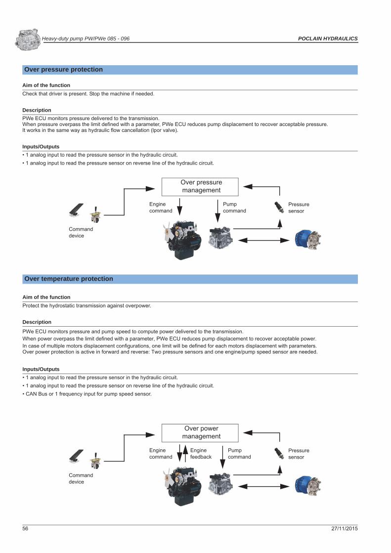
56 27/11/2015
Heavy-duty pump PW/PWe 085 - 096 POCLAIN HYDRAULICS
Over pressure protection
Aim of the functionCheck that driver is present. Stop the machine if needed.
DescriptionPWe ECU monitors pressure delivered to the transmission. When pressure overpass the limit defined with a parameter, PWe ECU reduces pump displacement to recover acceptable pressure.It works in the same way as hydraulic flow cancellation (lpor valve).
Inputs/Outputs• 1 analog input to read the pressure sensor in the hydraulic circuit.• 1 analog input to read the pressure sensor on reverse line of the hydraulic circuit.
Over temperature protection
Aim of the functionProtect the hydrostatic transmission against overpower.
Description
PWe ECU monitors pressure and pump speed to compute power delivered to the transmission.When power overpass the limit defined with a parameter, PWe ECU reduces pump displacement to recover acceptable power.In case of multiple motors displacement configurations, one limit will be defined for each motors displacement with parameters.Over power protection is active in forward and reverse: Two pressure sensors and one engine/pump speed sensor are needed.
Inputs/Outputs• 1 analog input to read the pressure sensor in the hydraulic circuit.• 1 analog input to read the pressure sensor on reverse line of the hydraulic circuit.• CAN Bus or 1 frequency input for pump speed sensor.
Over pressuremanagement
Enginecommand
Pumpcommand
Commanddevice
Pressuresensor
Over powermanagement
Enginecommand
Pumpcommand
Commanddevice
Pressuresensor
Enginefeedback

27/11/2015 57
POCLAIN HYDRAULICS Heavy-duty pump PW/PWe 085 - 096
Mod
elC
ode
Tech
nica
l sp
ecifi
catio
nsO
pera
ting
Para
met
ers
Syst
em d
esig
n Pa
ram
eter
sFe
atur
esPW
e in
stal
latio
nC
ontr
ols
Opt
ions
PWe
pack
age
desc
riptio
n
Engine over speed protection
Aim of the functionProtect the engine against overspeed.
DescriptionPWe ECU monitors motor/pump speed.When engine speed overpass a limit defined with a parameter, PWe ECU will limit hydrostatic deceleration to recover acceptable enginespeed.
ErgonomicsAccording to engine speed, ramp of deceleration will be adjusted (time to decelerate is increased) to limit hydrostatic deceleration. Deceleration will be automatically adjusted to the engine braking performances whatever is the slope or the load of the machine. To ensure that the driver will be able to stop the machine, a braking device is mandatory (braking/inching or combined braking).
Inputs/Outputs• CAN Bus or 1 frequency input for pump speed sensor.• 1 analog input for braking pressure sensor or braking pedal sensor.
Diagnostic
Aim of the functionGive driver feedback on transmission status.
DescriptionPWe ECU detects errors on the system and informs the user.
Ergonomics
Two configurations:Failure lamp: • Blinking in case of error.Display: • Displays error code and cause.
• Displays transmission information (speed, power, ...).
Inputs/Outputs• 1 digital output for failure lamp.• CAN bus for display.
Over-speed limitationmanagement
Enginecommand
Enginefeedback
Pumpcommand
Brake pedal
Diagnosticmanagement
SD-Display-1.5 Failure lamp
CAN-Bus Wired

58 27/11/2015
Heavy-duty pump PW/PWe 085 - 096 POCLAIN HYDRAULICS
Command device
Aim of the functionDefine user ergonomics.
Ergonomics
Possibility to select:
• Travel pedal (1 signal or 2 signals for redundancy) associated with forward/reverse direction switches or forward/neutral/reverse direction switches (for redundancy).• Joystick (1 signal or 2 signals for redundancy).• DA-like (pump speed defines pump displacement). A braking is mandatory to ensure deceleration if engine stays at high speed.
Inputs/Outputs
Joystick:• 1 analog input to read the joystick or 2 analog inputs for redundancy.• 1 digital input for joystick neutral switch.
Travel pedal:• 1 analog input to read the travel pedal or 2 analog inputs for redundancy. • 2 digital inputs for forward/reverse or 3 digital inputs for forward/neutral/reverse.
DA-like:• 1 frequency input for pump speed sensor.• 2 digital inputs for forward/reverse or 3 digital inputs for forward/neutral/reverse.
Command devicemanagement
Enginecommand
Pumpcommand
Commanddevice
Directionswitches
Pump/Enginespeed

27/11/2015 59
POCLAIN HYDRAULICS Heavy-duty pump PW/PWe 085 - 096
Mod
elC
ode
Tech
nica
l sp
ecifi
catio
nsO
pera
ting
Para
met
ers
Syst
em d
esig
n Pa
ram
eter
sFe
atur
esPW
e in
stal
latio
nC
ontr
ols
Opt
ions
PWe
pack
age
desc
riptio
n
Start-up check
Aim of the functionEnsure that all conditions are valid before making machine move after a powering up.
ErgonomicsEnsures that after PWe ECU powering up, embedded software checks PWe ECU supply voltage, internal supply voltage, command device, direction switches, pump feedback and parameters values (all at the same time).Ensures that after PWe ECU powering up, command device is seen at 0% and the direction switches are in neutral (all at the same time).
Check of battery voltageAn error occurs if battery voltage is below 9V or above 30V.
Pump loop errorAn error occurs in case of difference between pump command and real displacement of the pump based on calculation using pump feedback sensor. The machine stops.
Check of 5V supplyAn error occurs if the 5V supply provided by the PWe ECU is below 4.8V or above 5.2V. The machine stops.
Check Travel pedal or Joystick pedalAn error occurs if the signal from Travel Pedal or Joystick is below 0.25V or above 4.75V. The machine stops.
Simultaneous activation of Forward, Neutral and Reverse switches
These actions are done when two switches (or more) are in the same state:• Deceleration of machine according ramp.• Error activation on direction switches
Check of pump feedback sensor signalAn error occurs if the signal from the feedback sensor is below 0.25V or above 4.75V. The machine stops.
Check of parameters checksumAn error occurs in case of parameter checksum or calibration value checksum. Then machine stay at stop.
Battery voltage checking
Pump loop error checking
5V supply voltage checking
Command device signal checking
Simultaneous activation of Forward/Reverse checking
Pump feedback sensor signal checking
Parameters checksum checking

60 27/11/2015
Heavy-duty pump PW/PWe 085 - 096 POCLAIN HYDRAULICS
Hill start
Aim of the functionPrevent any rollback when starting in a slope.
DescriptionPWe ECU makes a jump on pump displacement to compensate leakages due to slope.
ErgonomicsTo activate hill start, driver must apply the park brake, provide a command device and then remove park brake.
Inputs/Outputs• 1 analog input for Travel pedal or Joystick.• 1 digital input for the park brake.
Proportional engine control
Aim of the functionDrive engine speed proportionally to the command device.
DescriptionEngine is controlled from minimum to maximum speed (parameters) proportionally to command device position.
ErgonomicsDriver uses command device to manage pump displacement and engine speed simultaneously.
Inputs/Outputs• CAN bus for engine (J1939 protocol).• Command device: joystick or pedal.
Hill startmanagement
Enginecommand
Pumpcommand
Command
Parkbrake
Driver command
Max RPM
Idle RPM
Engine

27/11/2015 61
POCLAIN HYDRAULICS Heavy-duty pump PW/PWe 085 - 096
Mod
elC
ode
Tech
nica
l sp
ecifi
catio
nsO
pera
ting
Para
met
ers
Syst
em d
esig
n Pa
ram
eter
sFe
atur
esPW
e in
stal
latio
nC
ontr
ols
Opt
ions
PWe
pack
age
desc
riptio
n
Fixed engine control
Aim of the functionMachine translation is managed with fixed engine speed.
DescriptionWhen driver requests the machine to move, PWe ECU drives the engine from idle speed to fixed speed. PWe ECU adjust machine speed with pump displacement only. After machine stops, PWe ECU waits for a parameter defined delay, then drives the engine speed to its idle speed.
Ergonomics• Driver uses standard joystick or pedal to require machine to move.• Driver uses a display to set the desired speed for fixed engine control.
Inputs/Outputs• Command device: joystick or pedal.• CAN bus for engine (J1939 protocol).• CAN bus for display.
Driver command
Idle RPM
Working RPM
Engine command

62 27/11/2015
Heavy-duty pump PW/PWe 085 - 096 POCLAIN HYDRAULICS
Mixed engine control
Aim of the functionPossibility for driver to select fixed engine control or a proportional engine control.
Description• Fixed engine control: when driver requests the machine to move, PWe ECU drives the engine from idle speed to fixed speed. PWe ECU adjusts machine speed with pump displacement only. After machine stops, PWe ECU waits for a parameter defined delay, then drives the engine speed to its idle speed.• Proportional engine control: engine is controlled from minimum to maximum speed (parameters) proportionally to command device position.
Ergonomics
Driver uses display to select between fixed engine control and proportional engine control.• For proportional engine control: driver uses command device to set machine and engine speed simultaneously.• For fixed engine control: driver uses standard joystick or pedal to require machine to move and uses a display to set the desired speed.
Inputs/Outputs• Command device. joystick or pedal.• CAN bus for engine (J1939 protocol).• CAN bus for display.
Driver command
Idle RPM
Working RPM
Max RPM
Use SD-Display to selectengine management mode.
Proportional engine control
Fixed engine control
Engine command

27/11/2015 63
POCLAIN HYDRAULICS Heavy-duty pump PW/PWe 085 - 096
Mod
elC
ode
Tech
nica
l sp
ecifi
catio
nsO
pera
ting
Para
met
ers
Syst
em d
esig
n Pa
ram
eter
sFe
atur
esPW
e in
stal
latio
nC
ontr
ols
Opt
ions
PWe
pack
age
desc
riptio
n
CAN broadcasting
Aim of the functionSend transmission information through CAN bus for driver display and diagnostic purpose.
DescriptionSend transmission information accordingly to J1939: Pump command
Pump flowPump speedDriver commandBrake commandInching commandHigh pressure AHigh pressure BMachine speedModeDirectionPowerOver power protection statusOver pressure protectin statusAnti-stall statusEngine overspeed statusSpeed control loop statusTemperature protection statusError codes
Inputs/Outputs• CAN bus (J1939 protocol).
ECU 2 ECU 3ECU 1
Display

64 27/11/2015
Heavy-duty pump PW/PWe 085 - 096 POCLAIN HYDRAULICS
CAN Bus J1939 standardThis function builds CAN Bus frames following J1939 standard and puts these frames on the bus. These frames can be read by customer´s CAN bus display. These frames are sent each 40ms ne frame, so 5 frames are repeated each 200ms. Sending of these frames can be disabled/enabled by parameter “CAN_J1939”.
PH SPN Signal Name Representation Length Limits (Range) Notes0 Pump1 Command H 2 bytes 0 to 65535 cc1 Pump2 Command H 2 bytes 0 to 65535 cc Not used2-4 reserved
5 Pump1 flow A 3 bytes 0 to 838860,8 L/h0 to 13981,01 L/min
6 Pump2 flow A 3 bytes 0 to 838860,8 L/h0 to 1981,01 L/min Not used
7-9 reserved10 Pump1 speed D 2 bytes 0 to 8191,87 rpm11 Pump2 speed D 2 bytes 0 to 8191, 87 rpm Not used12-14 reserved15-19 reserved20 Driver command B 1 byte -100 to 100 %21-24 reserved25 Brake command B 1 byte -100 to 100 %26-29 reserved30 Inching command B 1 byte -100 to 100 %31-34 reserved35-39 reserved
40 High pressure A C 2 bytes 0 to 1 048 560 kPa0 to 10 485,6 bar
41 High pressure B C 2 bytes 0 to 1 048 560 kPa0 to 10 485,6 bar
42-49 reserved
50 Machine speed measured 2 bytes 0 to 255,99 km/h Not used
51 Machine speed flow G 2 bytes 0 to 255,99 km/h52-59 reserved
60 Mode J 4 bits
Transmission:0 = Neutral1 = Work mode2 = Road modeAssist:0 = Freewheel1 = Assist2 = CreepCDM:0 = Freewheel1 = Creep
Not used
61 Actual gear E 4 bits
0 = Undefined1 = Gear 12 = Gear 2...15 = Gear 15
Not used
62 Direction F/N/R I 2 bits
0 = Neutral1 = Forward2 = Reverse3 = Not available
63 Limp mode code K 1 byte 0 to 255 Not used
64 Limp mode activation I 2 bits
0 = Not Active1 = Active2 = Not defined3 = Not available
Not used
65 Power level 1 F 2 bytes 0 to 32 767,5 kW66 Power level 2 F 2 bytes 0 to 32 767,5 kW67-69 reserved

27/11/2015 65
POCLAIN HYDRAULICS Heavy-duty pump PW/PWe 085 - 096
Mod
elC
ode
Tech
nica
l sp
ecifi
catio
nsO
pera
ting
Para
met
ers
Syst
em d
esig
n Pa
ram
eter
sFe
atur
esPW
e in
stal
latio
nC
ontr
ols
Opt
ions
PWe
pack
age
desc
riptio
nPGN definitions
70 Power limitation 1 activated I 2 bits
0 = Not active1 = Active2 = Not defined3 = Not available
71 Power limitation 2 activated I 2 bits
0 = Not active1 = Active2 = Not defined3 = Not available
72-74 reserved
75 Pressure limiter 1 activated I 2 bits
0 = Not active1 = Active2 = Not defined3 = Not available
76 Pressure limiter 2 activated I 2 bits
0 = Not active1 = Active2 = Not defined3 = Not available
77-79 reserved
80 Torque limitation 1 activated I 2 bits
0 = Not active1 = Active2 = Not defined3 = Not available
Not used
81 Torque limitation 2 activated I 2 bits
0 = Not active1 = Active2 = Not defined3 = Not available
Not used
82-84 reserved
85 Antistall activated I 2 bits
0 = Not active1 = Active2 = Not defined3 = Not available
86 Engine overspeed activated I 2 bits
0 = Not active1 = Active2 = Not defined3 = Not available
87 Speed loop activated I 2 bits
0 = Not active1 = Active2 = Not defined3 = Not available
88 Temperature security status I 2 bits
0 = Not active1 = Active2 = Not defined3 = Not available
89 reserved
90
Active error codes every n seconds the SmartDrive will shift this value to the next active error code
K 1 byte0 = No error1-255 = Active Error code
91 PDU1 Format frame command 1 byte 1 = cf message PHR_1
Name Identifier (Hex) Byte Bit Comment/Parameter PH SPN Length of
resolutionOperating data range Notes
PH_1
18 FF 80 xx(P=6PGN = 65408SA = xxh)
1-2 Pump1 Command 0 1 cc/bit 0 to 65 535 cc3-5 Pump1 flow 5 0.05 L/h per bit 0 to 838 860,8 L/h6-7 Pump1 speed 10 0.125 rpm/bit 0 to 8 191,87 rpm8 Not used 0xFF
PH_2
18 FF 81 xx(P=6PGN = 65409SA = xxh)
1-2 Pump2 Command 1 1 cc/bit 0 to 65 535 cc Not used3-5 Pump2 flow 6 0.05 L/h per bit 0 to 838 860,8 L/h Not used6-7 Pump2 speed 11 0.125 rpm/bit 0 to 8 191,87 rpm Not used8 Not used 0xFF
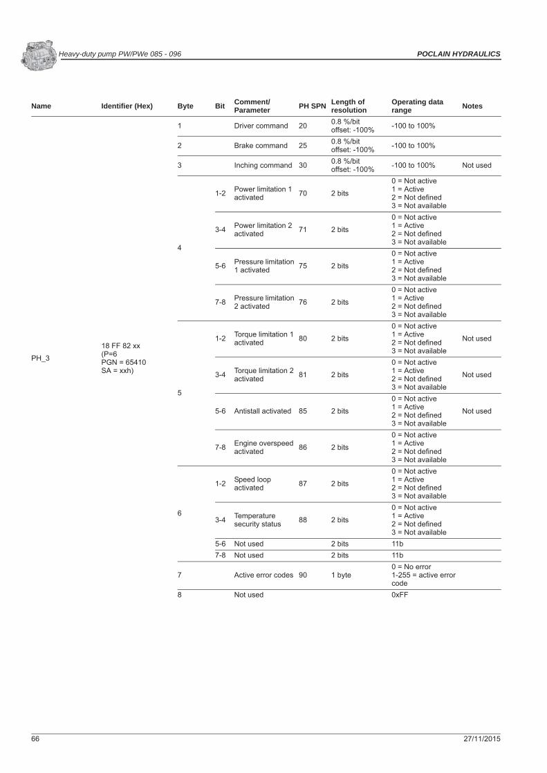
66 27/11/2015
Heavy-duty pump PW/PWe 085 - 096 POCLAIN HYDRAULICS
Name Identifier (Hex) Byte Bit Comment/Parameter PH SPN Length of
resolutionOperating data range Notes
PH_3
18 FF 82 xx(P=6PGN = 65410SA = xxh)
1 Driver command 20 0.8 %/bitoffset: -100% -100 to 100%
2 Brake command 25 0.8 %/bitoffset: -100% -100 to 100%
3 Inching command 30 0.8 %/bitoffset: -100% -100 to 100% Not used
4
1-2 Power limitation 1 activated 70 2 bits
0 = Not active1 = Active2 = Not defined3 = Not available
3-4 Power limitation 2 activated 71 2 bits
0 = Not active1 = Active2 = Not defined3 = Not available
5-6 Pressure limitation 1 activated 75 2 bits
0 = Not active1 = Active2 = Not defined3 = Not available
7-8 Pressure limitation 2 activated 76 2 bits
0 = Not active1 = Active2 = Not defined3 = Not available
5
1-2 Torque limitation 1 activated 80 2 bits
0 = Not active1 = Active2 = Not defined3 = Not available
Not used
3-4 Torque limitation 2 activated 81 2 bits
0 = Not active1 = Active2 = Not defined3 = Not available
Not used
5-6 Antistall activated 85 2 bits
0 = Not active1 = Active2 = Not defined3 = Not available
Not used
7-8 Engine overspeed activated 86 2 bits
0 = Not active1 = Active2 = Not defined3 = Not available
6
1-2 Speed loop activated 87 2 bits
0 = Not active1 = Active2 = Not defined3 = Not available
3-4 Temperature security status 88 2 bits
0 = Not active1 = Active2 = Not defined3 = Not available
5-6 Not used 2 bits 11b7-8 Not used 2 bits 11b
7 Active error codes 90 1 byte0 = No error1-255 = active error code
8 Not used 0xFF

27/11/2015 67
POCLAIN HYDRAULICS Heavy-duty pump PW/PWe 085 - 096
Mod
elC
ode
Tech
nica
l sp
ecifi
catio
nsO
pera
ting
Para
met
ers
Syst
em d
esig
n Pa
ram
eter
sFe
atur
esPW
e in
stal
latio
nC
ontr
ols
Opt
ions
PWe
pack
age
desc
riptio
n
Name Identifier (Hex) Byte Bit Comment/Parameter PH SPN Length of resolution
Operating data range Notes
PH_4
18 FF 83 xx(P=6PGN = 65411SA = xxh)
1-2 Machine speed measured 50 1/256 km/h per bit 0 to 255,99 km/h Not used
3-4 Machine speed flow 51 1/256 km/h per bit 0 to 255,99 km/h
5
1-4 Mode 60 4 bits
Transmission:0 = Neutral1 = Work mode2 = Road modeAssist:0 = Freewheel1 = Assist2 = CreepCDM:0 = Freewheel1 = Creep
Not used
5-8 Actual gear 61 4 bits
0 = Undefined1 = Gear 12 = Gear 2...15 = Gear 15
Not used
6
1-2 Direction (F/N/R) 62 2 bits
0 = Neutral1 = Forward2 = Reverse3 = Not available
3-4 Limp mode activated 64 2 bits
0 = Not active1 = Active2 = Not defined3 = Not available
Not used
5-8 Not used 4 bits 1111b7 Limp mode code 63 8 bits 0 to 255 Not used8 Not used 0xFF
PH_5
18 FF 84 xx(P=6PGN = 65412SA = xxh)
1-2 High pressure A 40 16 kPa/bit 0 to 1 048 560 kPa0 to 10 485,6 bar
3-4 High pressure B 41 16 kPa/bit 0 to 1 048 560 kPa0 to 10 485,6 bar
5-6 Power level 1 65 0.5 kW/bit 0 to 32 767,5 kW7-8 Power level 2 66 0.5 kW/bit 0 to 32 767,5 kW

68 27/11/2015
Heavy-duty pump PW/PWe 085 - 096 POCLAIN HYDRAULICS
Braking/Inching management
Aim of the function• Provide hydrostatic braking according to driver request (braking function).• Provide inching, reduced machine speed, according to driver request (inching function).
Description• Braking: PWe ECU manages hydrostatic braking (m/s²) proportionally to braking/inching pedal position.• Inching: PWe ECU manages requested machine speed thanks to: command device position x (1 – braking/inching pedal position).First part of pedal range is used for inching and second part for braking. Pedal position to switch from inching to braking is adjustable by parameter.
Ergonomics• When using braking, machine decelerates until stop. When releasing braking/inching pedal before machine stop, the driver will first have to bring the joystick or travel pedal back to the position matching the current vehicle speed to recover the full control of the speed.• When using inching, machine speed is reduced according to braking/inching pedal position, following standard deceleration ramp. When inching is released, machine recovers original speed following standard acceleration ramp.
Inputs/Outputs• 1 analog input or 2 analog inputs (for redundancy) to read braking/inching pedal position.• CAN bus for 1 frequency input for pump speed sensor.
Braking/Inchingmanagement
Enginecommand
Pumpcommand
Commanddevice
Braking/Inching pedal
Pump/Engine feedback
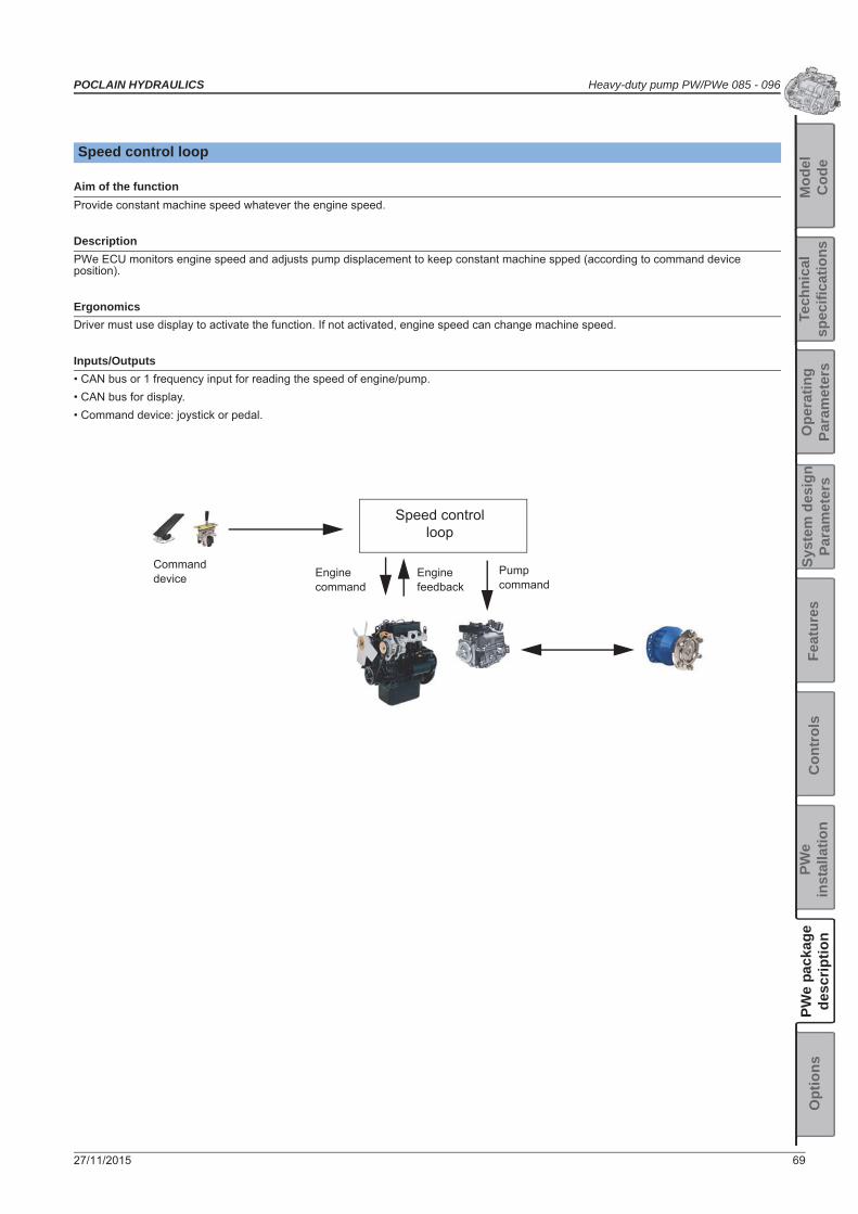
27/11/2015 69
POCLAIN HYDRAULICS Heavy-duty pump PW/PWe 085 - 096
Mod
elC
ode
Tech
nica
l sp
ecifi
catio
nsO
pera
ting
Para
met
ers
Syst
em d
esig
n Pa
ram
eter
sFe
atur
esPW
e in
stal
latio
nC
ontr
ols
Opt
ions
PWe
pack
age
desc
riptio
n
Speed control loop
Aim of the functionProvide constant machine speed whatever the engine speed.
DescriptionPWe ECU monitors engine speed and adjusts pump displacement to keep constant machine spped (according to command device position).
ErgonomicsDriver must use display to activate the function. If not activated, engine speed can change machine speed.
Inputs/Outputs• CAN bus or 1 frequency input for reading the speed of engine/pump.• CAN bus for display.• Command device: joystick or pedal.
Speed controlloop
Enginecommand
Pumpcommand
Commanddevice Engine
feedback

70 27/11/2015
Heavy-duty pump PW/PWe 085 - 096 POCLAIN HYDRAULICS
CAN slave management
Usage sum upCAN communication used by CAN slave is matching J1939 communication rules and frame definition. Used PGN are defined within customer specific ID range.To command the pump, following data are required:
• Pump direction (Neutral, direction A or direction B)• Pump enable (Active or not)• Pump command (in cc, with ramp management following parameter)
To improve safety of the command sent to the PWe pump throughout CAN bus, there is a counter that should be incremented each time a new can frame is transmitted. This counter is 8bits long and is free running. It will return to 0 after 255. A second message will be sent as redundancy purpose, it will contain one complemented data from main command frame. PWe ECU will check consistency between main and redundancy CAN frame. In case of recurrent discrepancy PWe pump will enter in safe mode and bring pump back to neutral.
Conditions of CAN communication that can stop the pump:
• If main or redundant messages are missing for 0.5s, pump will go back to neutral following a specific ramp (1.5s).• If main and redundant messages are inconsistent 3 times (consecutively) pump will go back to neutral following a specific ramp (1.5s). • If counter of main message isn’t increasing, pump will go back to neutral following a specific ramp (1.5s).
To ensure that redundant message will not be received before main message, redundant message will be sent at least 10ms after main message.After pump start-up an initial condition must be observed regarding the pump command to be able to stroke the pump. This initial condition must be:
• Pump command = 0cc• Pump enable = FALSE• Pump direction = Neutral
To inform master PWe ECU of transmission condition pump will send CAN frames containing pressure, speed, temperature information. Those information will be transmitted in two ways:
• Physical values, computed using parameters value defining sensor characteristics.
.
• Electrical values that are direct RAW reading. Master PWe ECU will have to compute by its own physical values based on its own parameters. Master PWe ECU will also have to take care of signal range validity to detect sensor disconnection
Parametres dedicated to CAN slave communication
Name Rate of PHPI messagesDescription Define the transmission period for PHPIx messages.Min. value 0,01sMax. value 0,20s
Name Rate of PHPC messages and pump control tasks.Description Define the typical period for PHPCx messages.Min. value 0,01sMax. value 0,10s
Name Ramp of deceleration in case of fault..
DescriptionDefine the ramp used to bring the pump back to neutral when CAN communication is lost with master PWe ECU. This parameter defines time in s taken to bring the pump from full displacement to neutral. (I.e. if the pump was stroked to half displacement when the fault occurred, it will take half the specified time to get back to neutral).
Min. value 0,5sMax. value 6553,4s
Name Wait for 1st valid command after powerUP.
Description Define the initial time allowed after PWe pump power up to start communication with master PWe ECU. This is intended to let time to master PWe ECU to boot up and start CAN communication without triggering errors.
Min. value 0,1sMax. value 30s

27/11/2015 71
POCLAIN HYDRAULICS Heavy-duty pump PW/PWe 085 - 096
Mod
elC
ode
Tech
nica
l sp
ecifi
catio
nsO
pera
ting
Para
met
ers
Syst
em d
esig
n Pa
ram
eter
sFe
atur
esPW
e in
stal
latio
nC
ontr
ols
Opt
ions
PWe
pack
age
desc
riptio
n
POCLAIN HYDRAULICS PUMP COMMAND#1 (PHPC1) - PGN 61184(Transmission rate: 10 - 100ms):
POCLAIN HYDRAULICS PUMP COMMAND#2 (PHPC2) - PGN 61184(Transmission rate: 10 - 100ms):
• For those messages DA value comes from “Own J1939 address in Slave” parameter.• For those messages SA value comes from “J1939 address of commander” parameter.
Name Own J1939 address in SlaveDescription J1939 address of PWe ECUMin. value 0Max. value 255
Name J1939 address of commanderDescription J1939 address of master PWe ECUMin. value 0Max. value 255
Details of CAN messages
INPUTS (Master to PWe pump):
Name Identifier (Hex) Byte Bit Comment/Parameter SPN Length or resolution Operating data range
PHPC1
18 EF yy xx(P=6 PGN=61148DA = yyhSA = xxh)
1 Data index 1 byte 01h = pump command
2 1-2 Pump direction 2 bits
00b = Neutral01b = Direction A10b = Direction B11b = Not defined (Neutral)
3-4 Pump enable 2 bits
00b = Not activated01b = Activated10b = Not defined (Not activated)11b = Not defined(Not activated)
5-8 Not used N/A 1111b
3-4 Pump command 2 bytes1/10th cc 0.0 to 6553.4 cc
5-6 Not used 2 bytes FFFFh7 Not used 1 byte FFh8 Command message counter 1 byte 0 to 255
Name Identifier (Hex) Byte Bit Comment/Parameter SPN Length or resolution Operating data range
PHPC2
18 EF yy xx(P6=6 PGN= 61148DA = yyhSA = xxh)
1 Data index 1 byte 02h = pump command redundancy
2 Data index 1 byte = ~PHPC1.byte83 Redundant signal 1 byte = ~PHPC1.byte74 Redundant signal 1 byte = ~PHPC1.byte65 Redundant signal 1 byte = ~PHPC1.byte56 Redundant signal 1 byte = ~PHPC1.byte47 Redundant signal 1 byte = ~PHPC1.byte38 Redundant signal 1 byte = ~PHPC1.byte2

72 27/11/2015
Heavy-duty pump PW/PWe 085 - 096 POCLAIN HYDRAULICS
POCLAIN HYDRAULICS PUMP INFO#1 (PHP11) - PGN 65386(Transmission rate: 10 - 100ms [parameter, 100ms by default]):
POCLAIN HYDRAULICS PUMP INFO#2 (PHPI2) - PGN 65387(Transmission rate: 10 - 100ms [parameter, 100ms by default]):
• For those messages SA value comes from “Own J1939 address in Slave” parameter.
OUTPUTS (PWe pump to master):
Name Identifier (Hex) Byte Bit Comment/Parameter SPN Length or resolution Operating data range
PHPI1
18 EF yy xx(P=6PGN=61148DA = yyhSA = xxh)
1-2 Pump displacement 2 bytes 1/10th cc 0.00 to 6553.4 cc FFFFh = N/A3-4 Pump feedback voltage 2 bytes mV 0000 to 5200 mV FFFFh = N/A
5-6 Drift voltage 2 bytes mV -5200 to 5200 mV offset: RAW = mV + 5200 FFFFh = N/A
71
Pump enabled isPumpOk() &
pumpEnable_received bool 0b = Pump disabled
1b = Pump enabled
2 S1 connection error bool 0b = Cnx OK1b = Cnx fault
3 S2 connection error bool 0b = Cnx OK1b = Cnx fault
4 Cut-off connection error bool 0b = Cnx OK1b = Cnx fault
5 By-pass connection error bool 0b = Cnx OK1b = Cnx fault
6 Loop error bool 0b = Error not active1b = Error active
7 Drift error bool 0b = Error not active1b = Error active
8 FB error bool 0b = Error not active1b = Error active
8 1 Pollution bool 0b = No pollution1b = Pollution
2 General safe state bool 0b = NoGSS1b = GSS
3-4 Pump direction 2 bits
00b = Neutral01b = Direction A10b = Direction B11b = Not defined (Neutral)
5 Initial frame received N/A 0b = Frame not received1b = Frame was received
6 Communication error flag N/A 0b = Error not active1b = Error active
7 Not used N/A 1b8 Not used N/A 1b
Name Identifier (Hex) Byte Bit Comment/Parameter SPN Length or resolution Operating data range
PHPI2
18 FF6Bxx(P=6PGN = 65386SA = xxh)
1-2 Power supply voltage 2 bytes 1mV/bit 0000 to32000 mVFFFFh = N/A
3-4 5V supply output 2 bytes 1 mV/bit 000000 to 5500 mVFFFFh = N/A
5-6 Max. pump displacement 2 bytes 1/10th cc 0.0 to 6553.4 ccFFFFh = N/A
7-8 Not used 2 bytes FFFFh

27/11/2015 73
POCLAIN HYDRAULICS Heavy-duty pump PW/PWe 085 - 096
Mod
elC
ode
Tech
nica
l sp
ecifi
catio
nsO
pera
ting
Para
met
ers
Syst
em d
esig
n Pa
ram
eter
sFe
atur
esPW
e in
stal
latio
nC
ontr
ols
Opt
ions
PWe
pack
age
desc
riptio
n
The pump can be equipped of sensors (temperature, pressure and speed). Their value will be send on the CAN bus.2 types of information on the CAN bus:• Physical value (in V or Hz)• Calculated value (in bars or RPM or °C)If the sensor voltage is out of valid range (0.5V – 4.5V), calculated value will be FFFFh. There is no management for sensors.With Phases we have possibility to modify sensor’s parameter for pressure and temperature sensors (Bar/Volt, Degree/Volt,...).
POCLAIN HYDRAULICS PUMP INFO#3 (PHPI3) - PGN 65388(Transmission rate: 10 - 100ms [parameter, 100ms by default]):
POCLAIN HYDRAULICS PUMP INFO#4 (PHPI4) - PGN 65389(Transmission rate: 10 - 100ms [parameter, 100ms by default]):
• For those messages SA value comes from “Own J1939 address in Slave” parameter.
Other available outputs:
Name Identifier (Hex) Byte Bit Comment/Parameter SPN Length or resolution Operating data range
PHPI3
18 FF6Dxx(P=6PGN=65386SA = xxh)
1-2 HPA pressure sensor voltage
2 bytes 1mV/bit 0000 to 5200 mV
3-4 HPA pressure sensor 2 bytes 16kPa/bit 000000 to 100000 kPaFFFFh = signal not present
5-6 HPB pressure sensor voltage 2 bytes 1mV/bit 0000 to5200 mV
7-8 HPB pressure sensor 2 bytes 16kPa/bit 000000 to 100000 kPaFFFFh = signal not present
Name Identifier (Hex) Byte Bit Comment/Parameter SPN Length or resolution Operating data range
PHPI4
18 FF6Dxx(P=6PGN=65386SA = xxh)
1-2 Speed sensor frequency 2 bytes 0,15 Hz/bit 0000 to 8500 Hz3-4 Speed sensor 2 bytes 0,125 RPM/bit 0000 to 5000 RPM
5-6 Temperature sensor voltage 2 bytes 1mV/bit 0000 to 5000 mV
FFFFh = signal not present
7 Temperature sensor 1 byte 1°C/bit-40°C to +210°Coffset: RAW = °C + 40FFFFh = signal not present
8 Not used 1 byte FFh

74 27/11/2015
Heavy-duty pump PW/PWe 085 - 096 POCLAIN HYDRAULICS

POCLAIN HYDRAULICS Heavy-duty pump PW/PWe 085 - 096
27/11/2015 75
Syst
em d
esig
n Pa
ram
eter
sM
odel
Cod
eO
pera
ting
Para
met
ers
Tech
nica
l sp
ecifi
catio
nsFe
atur
esO
ptio
nsC
ontr
ols
PWe
inst
alla
tion
PWe
pack
age
desc
riptio
n
OPTIONS
T4 speed sensor specification
Installed speed sensor or predisposition
Commercial name T4 SENSOR 12-44Part number A22082CLenght L 44 [1.73]Function Detect movements : rotation speedCompatibility Electronic transmission management
D M C O H1 H2 SFG L A8 50
9 60
P C E B
W eP
P W
T4 speed sensor (without rotation direction) 2Predisposition for speed sensor 8
45 m
in.
[1.7
7 m
in.]
3 [0
.12]
M12
8 [0
.31]
Y
1
2
3 4
L
A-A
To install the sensor, see the ''Installation guide'' brochure No. 801478197L.
Max. length Y = Standard number of pulses per revolution =
15,2 [0.60]9
140,9 [5.55]
A
AX
"X"

Heavy-duty pump PWe085-PWe096 POCLAIN HYDRAULICS
76 27/11/2015
Installed speed sensor or predisposition
FeaturesSupply voltage 8 - 30 V
Output type - 1 push-pull square frequency signal- Maximum load current: 20 mA- Voltage at low state: < 1.5 V- Voltage at high state: > (power supply voltage - 3.5 V)
Maximum range 1.15 mm [0.045’’]
Current consumption 20 mA max.
Frequency range 0 to 15 kHz
Operating temperature - 40°C to + 125°C [- 40°F to 257°F]
Material Stainless steel
Protection rating IP68 (sensitive side) / IP67 (connector side)
Electrical protection Reverse polarity
Connection of the speed sensorRemove the plastic plug on the connector.
Function Pin number
Power supply 1Not present 2Ground 3Square frequency signal 4
For the connection of connectors, please refer to the connection table and the general cabling plan contained in the installation brochure for your transmission.
Electrical connections 90° 180°Commercial name ELEC-CABLE-M12-90°-5000 ELEC-CABLE-M12-180°-5000Part number A04999J A07468S
Signals are not protected against short circuit to ground or supply.

POCLAIN HYDRAULICS Heavy-duty pump PW/PWe 085 - 096
27/11/2015 77
Syst
em d
esig
n Pa
ram
eter
sM
odel
Cod
eO
pera
ting
Para
met
ers
Tech
nica
l sp
ecifi
catio
nsFe
atur
esO
ptio
nsC
ontr
ols
PWe
inst
alla
tion
PWe
pack
age
desc
riptio
n
By-pass of orifices in SA control
• Pump control optional function. • Ensures fast pump response in normal working modes and in the same time ensures slow (safe) pump return to neutral position when
it´s required or in case of electronic failure. • Size of orifices has to be defined based on the application.
B
Ports mm [inch](P) inlet (S1) servo (S2) servo (T)
0,8 [0.031] 0,8 [0.031] 0,8 [0.031] N/A 1w/o 1,5 [0.059] 1,5 [0.059] N/A 2w/o 0,8 [0.031] 0,8 [0.031] N/A 3
D M C O H1 H2 SFG L A8 50
9 60
P C E B
W eP
P W
228
[8.9
8]18
3.8
[7.2
4]
T1 M4 S M3
T2
M1 A
BM2T3M5
H2
H1
L
V2
V1V3
V4

Heavy-duty pump PWe085-PWe096 POCLAIN HYDRAULICS
78 27/11/2015
Special paint or no paint
The pumps are delivered with Poclain Hydraulics black primer (RAL 9005) as standard.
Without control pressure cut-off valve
Control pressure cut-off valve is not mandatory for some specific applications where the pump is not used as main drive (e.g. assist drive).
DM C O H1 H2 SFG L A8 50
9 60
P C E B
W eP
P W
Consult your Poclain Hydraulics application engineer for other colors of primer or topcoat.
CM C O H1 H2 SFG L A8 50
9 60
P C E B
W eP
P W
T1 M4 S M3
T2
M1 A
BM2T3M5
H2
H1
L
V2
V1
M3
Port Function Size NormM3 Charge pressure 7/8-14 UNF-2B ISO 11926-1

POCLAIN HYDRAULICS Heavy-duty pump PW/PWe 085 - 096
27/11/2015 79
Syst
em d
esig
n Pa
ram
eter
sM
odel
Cod
eO
pera
ting
Para
met
ers
Tech
nica
l sp
ecifi
catio
nsFe
atur
esO
ptio
nsC
ontr
ols
PWe
inst
alla
tion
PWe
pack
age
desc
riptio
n
Exchange valve
Inside the pump cover, a purge valve can be fitted with discharge inside the pump casing by means of a calibrated hole. The exchange valve is useful in case the temperature of the oil in the closed circuit is too high.
HM C O H1 H2 SFG L A8 50
9 60
P C E B
W eP
P W
X
161
[6.3
4]
58,2[2.29]
194,5 [7.66]77,8[3.06]
108 [4.25]
"X"
T1 M4 S M3
T2
M1 A
M2T3M5
H2
H1
L
V2
V1V3
) (
B
L2
Setting of exchange valve should be approximately 3~5 bar [44~73 PSI] lower than for charge relief valve (see chapter “Charge pressure relief valve”, page 20).Consult with your Poclain Hydraulics application engineer for precise setting.
adjustment screw
P (bar)
Pressure drop
Q (L/min)
SpecificationExchange valve adjustment range
18 to 30 bar[261 to 435 PSI]
Exchange flow(10 bar [145 PSI] P)
60 L/min[15.85 gal/min]
Exchange direction Forward and/or reverse
Example: relief valve set at 20 bar

Heavy-duty pump PWe085-PWe096 POCLAIN HYDRAULICS
80 27/11/2015
Pressure sensor specification
2-bolt bearing flange mounting&
All length dimensions of pump body with different auxiliary mounting pads are shorter compare to standard 4-bolt flange of 14 mm [0.55 inch].
Pressure sensors on A&B lines
The pump can be equipped with 600 bar [8702 PSI] pressure sensors.
Commercial name PRES-SENSOR-600B-G1/4-DINPart number A53472WCompatibility Electronic transmission management
MM C O H1 H2 SFG L A8 50
9 60
P C E B
W eP
P W
90,5[3.56]
90,5[3.56]
2x Ø 17,5 [dia. 0.69 ]
+0,3- 0,1+0.012- 0.004
15 [0.59]
max. 281 [11.06]*56[2.20]
Bearing life and maximum overhung moment is significantly lower compare to 4 bolt flange, see page 16 for Bearing life (B10 hours) and page 17 for allowable moment values.
RM C O H1 H2 SFG L A8 50
9 60
P C E B
W eP
P W
235 [9.25]
59[2
.32]
63[2
.48]
59 [2.32]
18°

POCLAIN HYDRAULICS Heavy-duty pump PW/PWe 085 - 096
27/11/2015 81
Syst
em d
esig
n Pa
ram
eter
sM
odel
Cod
eO
pera
ting
Para
met
ers
Tech
nica
l sp
ecifi
catio
nsFe
atur
esO
ptio
nsC
ontr
ols
PWe
inst
alla
tion
PWe
pack
age
desc
riptio
n
Pressure sensors on A&B lines
FeaturesSupply voltage 5 V ± 0,5 V
Output signal 0,5 V ~ 4,5 V ratiometric
Pressure range 600 bar [8702 PSI]
Over pressure safety 1200 bar [17404 PSI]
Pressure connection with VITONrectangular seal G 1/4” (DIN 3852-E)
Response time < 5 ms
Accuracy < 1%
Using temperature range
Medium - 40 °C to 125 °C [- 40 °F to 257 °F]
Ambient - 40 °C to 100 °C [- 40 °F to 212 °F]
Storage - 40 °C to 120 °C [- 40 °F to 248 °F]
Ingress protection IP69K (IEC 60529)
CE conformity EN 61326
Overvoltage and reverse polarity protection ± 30 VShock resistance 500 g according to DIN EN 837
Vibration resistance 20 g according to IEC 68-2
Electrical connection DIN 72585, 4 pins
1: +5 VDC2: Ground3: Output signal4: Not used
1
2
3
4

Heavy-duty pump PWe085-PWe096 POCLAIN HYDRAULICS
82 27/11/2015
Temperature sensor specification
Temperature sensor
The pump can be equipped with analog temperature sensor.
Commercial name TEMP-SENSOR-ANALOG-G1/4-M12Part number A22147XCompatibility Electronic transmission managementFonction Measure the temperature of the hydraulic circuit
FeaturesPower supply 5V ± 0.5 V
Output signal0.5 V to 4.5 V radiometricSaturation at 0.4 V for temperatures < -23°C [-9.4°F]
Response time 5 s
Accuracy ±1.5% FS from -20°C [-4°F] to 0°C [32°F]±1% FS from 0°C [32°F] to 120°C [248°F]
Permissible pressure 750 bar [10 877 PSI]
Using temperature range -20 to +120°C [-4 to +248°F]
Housing material Inox 304
Ingress protection IP67
Electrical protection- Over voltage: 30 V- Reverse polarity,- Short circuit.
Shock resistance 1m 3 axes
Vibration resistance 20 g
Electrical connection 90° 180°Commercial name ELEC-CABLE-M12-90°-5000 ELEC-CABLE-M12-180°-5000Part No. A04999J A07468S
1: nc2:+5 V3: Output signal 0,5 ~ 4,5 V4: 0 V (Ground)
TM C O H1 H2 SFG L A8 50
9 60
P C E B
W eP
P W
110 [4.33] 124,5 [4.90]
15°
58 [2.2
8]
120-20
4,5
0,5
-23
0,4
V
°C
1 2
3 4

POCLAIN HYDRAULICS Heavy-duty pump PW/PWe 085 - 096
27/11/2015 83
Syst
em d
esig
n Pa
ram
eter
sM
odel
Cod
eO
pera
ting
Para
met
ers
Tech
nica
l sp
ecifi
catio
nsFe
atur
esO
ptio
nsC
ontr
ols
PWe
inst
alla
tion
PWe
pack
age
desc
riptio
n

www.poclain-hydraulics.com
Poclain Hydraulics reserves the right to make any modifications it deems necessary to the products described in this document without prior notification.The information contained in this document must be confirmed by Poclain Hydraulics before any order is submitted.Illustrations are not binding.The Poclain Hydraulics brand is the property of Poclain Hydraulics S.A.
B03739N
27/11/2015