px-320 midi implementation - support · 19 b04 04 midi/music library channel04 music library...
TRANSCRIPT
1
Part I MIDI Message Overview
1 Product Configuration as a MIDI Device.......................................................................................... 51.1 System Section.................................................................................................................................... 51.2 Performance Controller Section .......................................................................................................... 5
1.3 Auto Accompaniment and Auto Performance MIDI Send ................................................................... 5
1.4 Sound Generator Section .................................................................................................................... 61.4.1 Sound Generator Common Block ..........................................................................................................61.4.2 Part Block...............................................................................................................................................6
2 Conditions that Disable Message Send and Receive...................................................................... 7
3 Timbre Type Specific Operation ...................................................................................................... 7
Part II Channel Message
4 Receive Channel ............................................................................................................................. 8
5 Send Channel .................................................................................................................................. 8
6 Note Off ........................................................................................................................................... 8
7 Note On ........................................................................................................................................... 8
8 Polyphonic Key Pressure................................................................................................................. 9
9 Control Change................................................................................................................................ 99.1 Bank Select (00H) ............................................................................................................................... 9
9.2 Modulation (01H) ............................................................................................................................... 109.3 Data Entry (06H,26H) ........................................................................................................................ 10
9.4 Volume (07H) .................................................................................................................................... 10
9.5 Pan (0AH).......................................................................................................................................... 119.6 Expression (0BH) .............................................................................................................................. 11
9.7 General Use Controllers 1 through 8 (10H through 13H, 50H through 53H)..................................... 11
9.8 Hold1 (40H) ....................................................................................................................................... 129.9 Sostenuto (42H) ................................................................................................................................ 12
9.10 Soft (43H) .......................................................................................................................................... 13
9.11 Vibrato Rate (4CH) ............................................................................................................................ 139.12 Vibrato Depth (4DH) .......................................................................................................................... 13
9.13 Vibrato Delay (4EH)........................................................................................................................... 14
9.14 Reverb Send (5BH) ........................................................................................................................... 149.15 Chorus Send (5DH) ........................................................................................................................... 14
PX-320 MIDI Implementation
CASIO COMPUTER CO., LTD.
Contents
2
9.16 NRPN (62H,63H)............................................................................................................................... 15
9.17 RPN (64H,65H) ................................................................................................................................. 159.17.1 Pitch Bend Sensitivity ..........................................................................................................................159.17.2 Fine Tune..............................................................................................................................................169.17.3 Coarse Tune..........................................................................................................................................169.17.4 Modulation Depth ................................................................................................................................169.17.5 Null.......................................................................................................................................................16
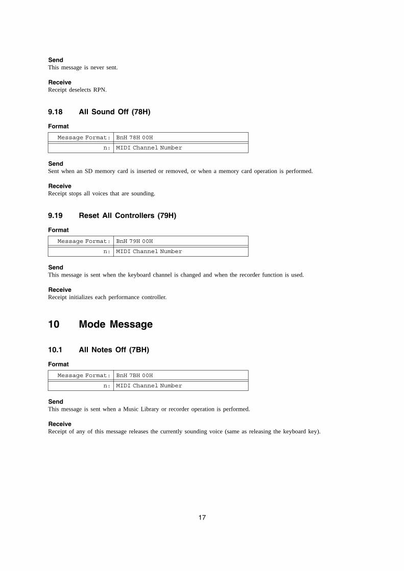
9.18 All Sound Off (78H) ........................................................................................................................... 179.19 Reset All Controllers (79H)................................................................................................................ 17
10 Mode Message .............................................................................................................................. 1710.1 All Notes Off (7BH) ............................................................................................................................ 17
10.2 Omni Off (7CH).................................................................................................................................. 1810.3 Omni On (7DH).................................................................................................................................. 18
10.4 Mono (7EH) ....................................................................................................................................... 18
10.5 Poly (7FH) ......................................................................................................................................... 18
11 Program Change ........................................................................................................................... 1911.1 About the Timbre Type ...................................................................................................................... 19
11.2 DSP Assignments During Tone Selection ......................................................................................... 19
11.2.1 DSP Line Structure...............................................................................................................................1911.2.2 DSP Line Assignment ..........................................................................................................................1911.2.3 Use of the Same DSP Line by Multiple Parts ......................................................................................20
12 Channel Aftertouch ........................................................................................................................ 20
13 Pitch Bend ..................................................................................................................................... 20
Part III System Messages
14 Active Sensing ............................................................................................................................... 21
15 System Exclusive Message ........................................................................................................... 2115.1 Universal Realtime System Exclusive Message................................................................................ 21
15.1.1 Master Volume.....................................................................................................................................2115.1.2 Master Balance.....................................................................................................................................2215.1.3 Master Fine Tuning ..............................................................................................................................2215.1.4 Master Coarse Tuning ..........................................................................................................................2215.1.5 Reverb Parameter .................................................................................................................................2315.1.6 Chorus Parameter .................................................................................................................................2315.1.7 GM System Message............................................................................................................................2515.1.8 GS Message..........................................................................................................................................25
15.2 Instrument-Specific System Exclusive Message ............................................................................... 26
Part IV Instrument-Specific System Exclusive Messages
16 Format ........................................................................................................................................... 2716.1 Message Classifications .................................................................................................................... 2716.2 Basic Message Structure................................................................................................................... 27
3
16.3 Format of Each Field ......................................................................................................................... 28
16.3.1 SX : System Exclusive Message Status ...............................................................................................2816.3.2 MAN : Manufacturer's ID ....................................................................................................................2816.3.3 MOD : Model ID..................................................................................................................................2816.3.4 dev : MIDI Device ID 00H-7FH ..........................................................................................................2816.3.5 act : Action ...........................................................................................................................................2916.3.6 cat : Category .......................................................................................................................................3016.3.7 mem : Memory Area ID .......................................................................................................................3116.3.8 pset : Parameter Set Number................................................................................................................3116.3.9 blk : Block Number ..............................................................................................................................3116.3.10 pkt : Packet Number .............................................................................................................................3216.3.11 prm : Parameter ID...............................................................................................................................3216.3.12 idx : Data Index Number ......................................................................................................................3216.3.13 len : Data Length ..................................................................................................................................3216.3.14 data : Parameter Data...........................................................................................................................3216.3.15 img : Parameter Set Image ...................................................................................................................3316.3.16 sum : Check Sum..................................................................................................................................3316.3.17 EOX : End of System Exclusive Message ...........................................................................................34
17 Individual Parameter Operations ................................................................................................... 34
18 Parameter Set Transfer Modes ..................................................................................................... 3418.1 Communication Modes...................................................................................................................... 34
18.1.1 One-way and Handshake......................................................................................................................3418.1.2 Session and Subsession ........................................................................................................................35
18.2 One-way Mode Communication Flow................................................................................................ 3518.3 Handshake Mode Communication Flow............................................................................................ 36
Part V Parameter List
19 System Parameters ....................................................................................................................... 3919.1 System Information Parameter.......................................................................................................... 39
19.2 Data Management Parameter ........................................................................................................... 39
20 Setup Parameter............................................................................................................................ 4020.1 MIDI Parameter ................................................................................................................................. 40
21 Patch Parameters .......................................................................................................................... 4021.1 Master Tune Parameter..................................................................................................................... 40
21.2 Master Mixer Parameter .................................................................................................................... 40
21.3 System Chorus Parameter ................................................................................................................ 4021.4 System Reverb Parameter ................................................................................................................ 41
21.5 System Acoustic Resonance Parameter ........................................................................................... 41
21.6 Brilliance Parameter .......................................................................................................................... 4121.7 Part Parameter .................................................................................................................................. 42
22 Tone Parameters ........................................................................................................................... 4222.1 Basic Parameters .............................................................................................................................. 42
22.2 LFO Parameter.................................................................................................................................. 4322.3 DSP Parameter ................................................................................................................................. 43
23 Music Library Parameter................................................................................................................ 44
4
Part VI Parameter Set List
24 Music Library Parameter Set ......................................................................................................... 45
Part VII DSP Parameter List
25 Tone with DSP List ........................................................................................................................ 46
26 DSP Algorithm ID Table................................................................................................................. 4726.1 Monaural Tone DSP .......................................................................................................................... 4726.2 Stereo Tone DSP .............................................................................................................................. 47
27 DSP Parameter Table.................................................................................................................... 4727.1 Algorithm 0001 : Mono-Mono Tremolo Parameter ............................................................................ 47
27.2 Algorithm 0002 : Mono-Mono 3Band EQ Parameter......................................................................... 4727.3 Algorithm 0008 : Mono-Mono Enhancer Parameter .......................................................................... 48
27.4 Algorithm 000B : Mono-Stereo Auto Pan Parameter......................................................................... 48
27.5 Algorithm 0011 : Mono-Mono Wide 3Band EQ Parameter................................................................ 4827.6 Algorithm 0013 : Mono-Mono Distortion Parameter .......................................................................... 48
27.7 Algorithm 2001 : Stereo-Stereo 3Band EQ Parameter...................................................................... 48
27.8 Algorithm 200B : Mix-Stereo Eary Reflection .................................................................................... 4927.9 Algorithm 200C : Mono-Stereo Rotary Parameter............................................................................. 49
27.10 Algorithm 200D : Mono-Stereo Drive Rotary Parameter ................................................................... 49
27.11 Algorithm 2017 : Stereo-Stereo Wide 3Band EQ Parameter ............................................................ 49
Part VIII Setting Values and Send/Receive Values
28 Setting Value Tables...................................................................................................................... 5028.1 Off/On Setting Value Table................................................................................................................ 5028.2 Slow/Fast Setting Value Table .......................................................................................................... 50
28.3 Rotate/Brake Setting Value Table ..................................................................................................... 50
28.4 -64 - 0 - 63 Setting Value Table......................................................................................................... 5028.5 Pan Setting Value Table.................................................................................................................... 50
28.6 -100 - 0 - 99 Setting Value Table....................................................................................................... 50
28.7 Reverb Type Setting Value Table...................................................................................................... 5028.8 Chorus Type Setting Value Table...................................................................................................... 51
28.9 Equalizer Mid Frequency Setting Value Table .................................................................................. 51
28.10 Wide Band Equalizer Mid Frequency Setting Value Table................................................................ 5128.11 Brilliance Gain Setting Value Table ................................................................................................... 52
28.12 DSP Equalizer Gain Setting Value Table .......................................................................................... 52
Part IX MIDI Implementation Notation
29 Value Notation ............................................................................................................................... 5329.1 Hexadecimal Notation ....................................................................................................................... 5329.2 Binary Notation .................................................................................................................................. 53
5
Part I
MIDI Message Overview
1 Product Configuration as a MIDI DeviceAs a MIDI device, the instrument consists of the System Section, Performance Controller Section, and Sound Generator Section described below. Each of these sections can send and receive specific MIDI Messages in accordance with its function.
• System Section– Device Settings
• Sound Generator Section– Common
∗ Sound Generator Common Block∗ System Effect Block∗ Master Effect Block (Brilliance Function)∗ Mixer Master Block
– Channel Independent∗ Instrument Parts ∗ Insertion Effect Block∗ Mixer Channel Independent Block
• Performance Controller Section– Keyboard– Pedal and other real-time controllers– Auto Accompaniment and Auto Accompaniment function
1.1 System Section
The System Section is divided between a sound generator and functions that are not directly related to Instrument play.In addition to manipulating Instrument setting parameters, this section is also used to exchange commands and information. For example, parameters can be initialized upon receipt of a System Section MIDI message, and memory use information can be sent.
1.2 Performance Controller Section
The Performance Controller Section consists of the keyboard, pedal and other real-time controllers, as well as blocks that generate auto accompaniment, auto performance, and other performance information.An operation causes the corresponding message to be transmitted to the sound generator and to be sent from MIDI OUT. The channel number of the sent message is in accordance with Instrument's part number.
1.3 Auto Accompaniment and Auto Performance MIDI Send
This document includes information for each type of information that describes what operation causes the message to be sent. However, since there are so many messages sent by an auto accompaniment or auto performance operation, those messages are not covered herein.
6
1.4 Sound Generator Section
The Sound Generator Section consists of a common part that does not depend on the channel and a part that specific to each channel. Mainly it receives performance information and performs operations.
1.4.1 Sound Generator Common BlockThe common section consists of a sound generator setting blocks that do not depend on the sound generator part, such as system effects, mixer master control, etc. These can be controlled by system exclusive messages that are basically exclusive to this particular instrument, but several parameters also can be controlled by general universal system exclusive messages.
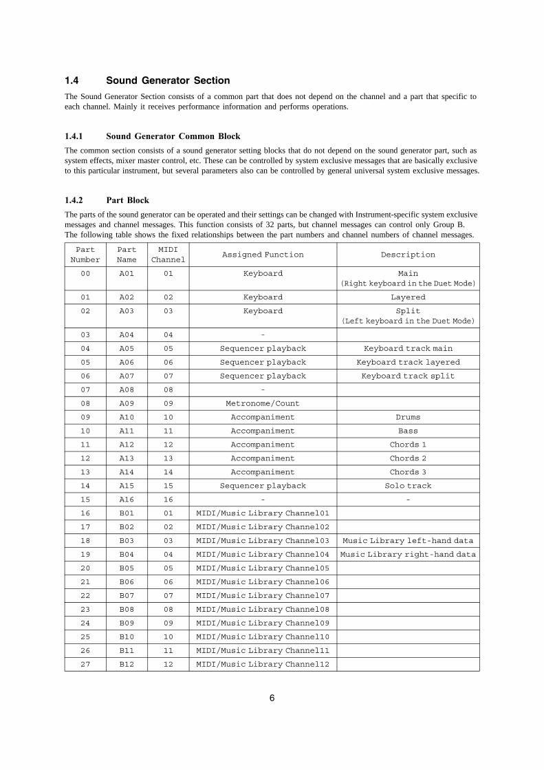
1.4.2 Part BlockThe parts of the sound generator can be operated and their settings can be changed with Instrument-specific system exclusive messages and channel messages. This function consists of 32 parts, but channel messages can control only Group B.The following table shows the fixed relationships between the part numbers and channel numbers of channel messages.
Part Number
Part Name
MIDI Channel
Assigned Function Description
00 A01 01 Keyboard Main(Right keyboard in the Duet Mode)
01 A02 02 Keyboard Layered
02 A03 03 Keyboard Split(Left keyboard in the Duet Mode)
03 A04 04 -
04 A05 05 Sequencer playback Keyboard track main
05 A06 06 Sequencer playback Keyboard track layered
06 A07 07 Sequencer playback Keyboard track split
07 A08 08 -
08 A09 09 Metronome/Count
09 A10 10 Accompaniment Drums
10 A11 11 Accompaniment Bass
11 A12 12 Accompaniment Chords 1
12 A13 13 Accompaniment Chords 2
13 A14 14 Accompaniment Chords 3
14 A15 15 Sequencer playback Solo track
15 A16 16 - -
16 B01 01 MIDI/Music Library Channel01
17 B02 02 MIDI/Music Library Channel02
18 B03 03 MIDI/Music Library Channel03 Music Library left-hand data
19 B04 04 MIDI/Music Library Channel04 Music Library right-hand data
20 B05 05 MIDI/Music Library Channel05
21 B06 06 MIDI/Music Library Channel06
22 B07 07 MIDI/Music Library Channel07
23 B08 08 MIDI/Music Library Channel08
24 B09 09 MIDI/Music Library Channel09
25 B10 10 MIDI/Music Library Channel10
26 B11 11 MIDI/Music Library Channel11
27 B12 12 MIDI/Music Library Channel12
7
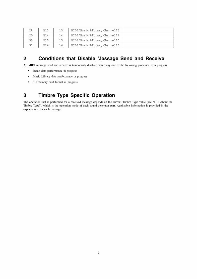
2 Conditions that Disable Message Send and ReceiveAll MIDI message send and receive is temporarily disabled while any one of the following processes is in progress.
• Demo data performance in progress
• Music Library data performance in progress
• SD memory card format in progress
3 Timbre Type Specific OperationThe operation that is performed for a received message depends on the current Timbre Type value (see "11.1 About the Timbre Type"), which is the operation mode of each sound generator part. Applicable information is provided in the explanations for each message.
28 B13 13 MIDI/Music Library Channel1329 B14 14 MIDI/Music Library Channel1430 B15 15 MIDI/Music Library Channel1531 B16 16 MIDI/Music Library Channel16
8
Part II
Channel Message
4 Receive ChannelThe channel number of the channel message received by each part is shown in the table under "1.4.2 Part Block". The channel number of a channel message that changes the settings of a DSP coincides with the channel of the part that is using the DSP.
5 Send ChannelBasically, the MIDI channel of the channel message sent when the Instrument is played coincides with the MIDI channel of the part being played. Note, however, that the MIDI channel of the performance information that corresponds to the keyboard main part is the Keyboard Channel setting value.
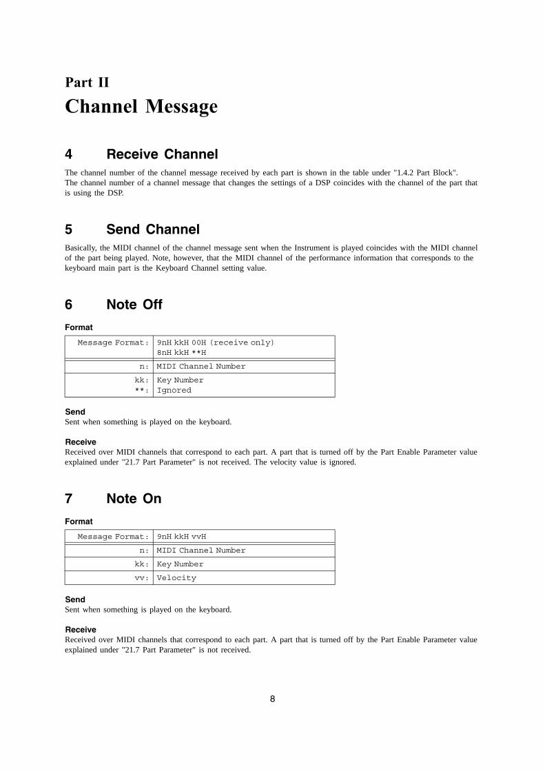
6 Note Off
Format
SendSent when something is played on the keyboard.
ReceiveReceived over MIDI channels that correspond to each part. A part that is turned off by the Part Enable Parameter value explained under "21.7 Part Parameter" is not received. The velocity value is ignored.
7 Note On
Format
SendSent when something is played on the keyboard.
ReceiveReceived over MIDI channels that correspond to each part. A part that is turned off by the Part Enable Parameter value explained under "21.7 Part Parameter" is not received.
Message Format: 9nH kkH 00H (receive only)8nH kkH **H
n: MIDI Channel Number
kk:**:
Key NumberIgnored
Message Format: 9nH kkH vvH
n: MIDI Channel Number
kk: Key Number
vv: Velocity
9
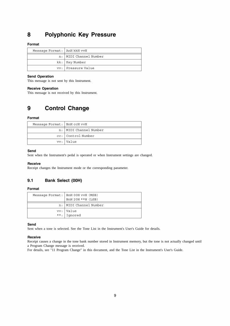
8 Polyphonic Key Pressure
Format
Send OperationThis message is not sent by this Instrument.
Receive OperationThis message is not received by this Instrument.
9 Control Change
Format
SendSent when the Instrument's pedal is operated or when Instrument settings are changed.
ReceiveReceipt changes the Instrument mode or the corresponding parameter.
9.1 Bank Select (00H)
Format
SendSent when a tone is selected. See the Tone List in the Instrument's User's Guide for details.
ReceiveReceipt causes a change in the tone bank number stored in Instrument memory, but the tone is not actually changed until a Program Change message is received.For details, see "11 Program Change" in this document, and the Tone List in the Instrument's User's Guide.
Message Format: AnH kkH vvH
n: MIDI Channel Number
kk: Key Number
vv: Pressure Value
Message Format: BnH ccH vvH
n: MIDI Channel Number
cc: Control Number
vv: Value
Message Format: BnH 00H vvH (MSB)BnH 20H **H (LSB)
n: MIDI Channel Number
vv:**:
ValueIgnored
10
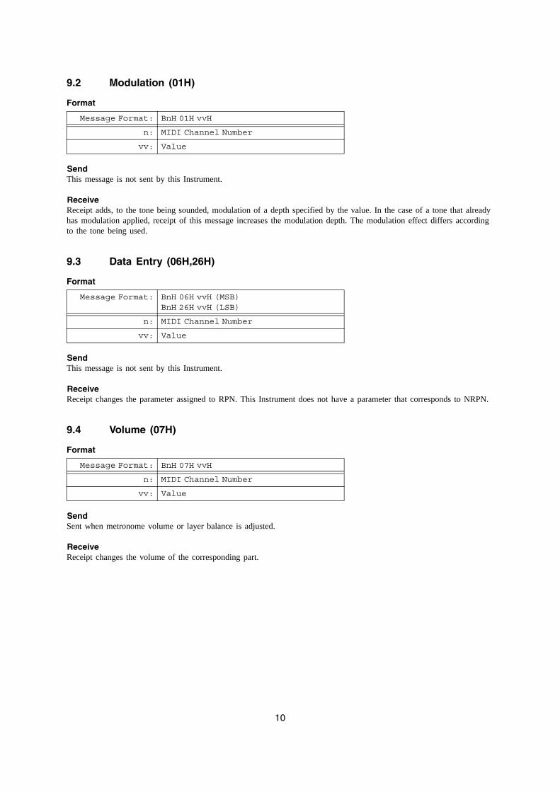
9.2 Modulation (01H)
Format
SendThis message is not sent by this Instrument.
ReceiveReceipt adds, to the tone being sounded, modulation of a depth specified by the value. In the case of a tone that already has modulation applied, receipt of this message increases the modulation depth. The modulation effect differs according to the tone being used.
9.3 Data Entry (06H,26H)
Format
SendThis message is not sent by this Instrument.
ReceiveReceipt changes the parameter assigned to RPN. This Instrument does not have a parameter that corresponds to NRPN.
9.4 Volume (07H)
Format
SendSent when metronome volume or layer balance is adjusted.
ReceiveReceipt changes the volume of the corresponding part.
Message Format: BnH 01H vvH
n: MIDI Channel Number
vv: Value
Message Format: BnH 06H vvH (MSB)BnH 26H vvH (LSB)
n: MIDI Channel Number
vv: Value
Message Format: BnH 07H vvH
n: MIDI Channel Number
vv: Value
11
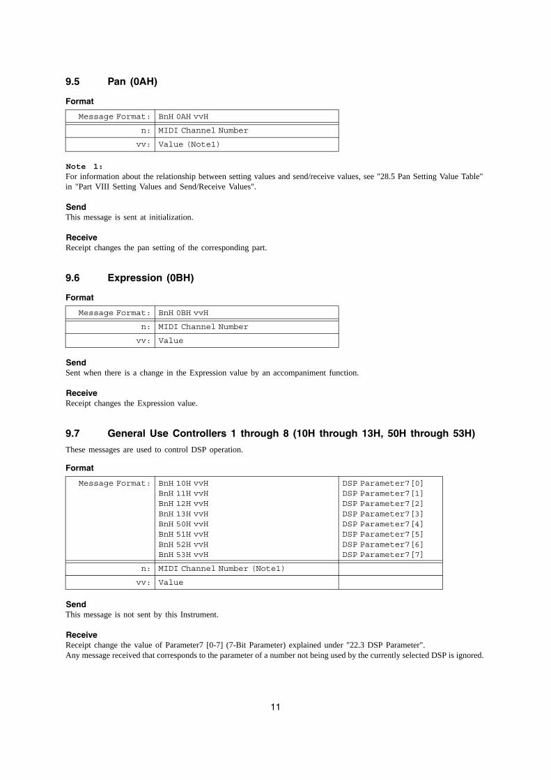
9.5 Pan (0AH)
Format
Note 1:For information about the relationship between setting values and send/receive values, see "28.5 Pan Setting Value Table" in "Part VIII Setting Values and Send/Receive Values".
SendThis message is sent at initialization.
ReceiveReceipt changes the pan setting of the corresponding part.
9.6 Expression (0BH)
Format
SendSent when there is a change in the Expression value by an accompaniment function.
ReceiveReceipt changes the Expression value.
9.7 General Use Controllers 1 through 8 (10H through 13H, 50H through 53H)
These messages are used to control DSP operation.
Format
SendThis message is not sent by this Instrument.
ReceiveReceipt change the value of Parameter7 [0-7] (7-Bit Parameter) explained under "22.3 DSP Parameter".Any message received that corresponds to the parameter of a number not being used by the currently selected DSP is ignored.
Message Format: BnH 0AH vvH
n: MIDI Channel Number
vv: Value (Note1)
Message Format: BnH 0BH vvH
n: MIDI Channel Number
vv: Value
Message Format: BnH 10H vvHBnH 11H vvHBnH 12H vvHBnH 13H vvHBnH 50H vvHBnH 51H vvHBnH 52H vvHBnH 53H vvH
DSP Parameter7[0]DSP Parameter7[1]DSP Parameter7[2]DSP Parameter7[3]DSP Parameter7[4]DSP Parameter7[5]DSP Parameter7[6]DSP Parameter7[7]
n: MIDI Channel Number (Note1)
vv: Value
12
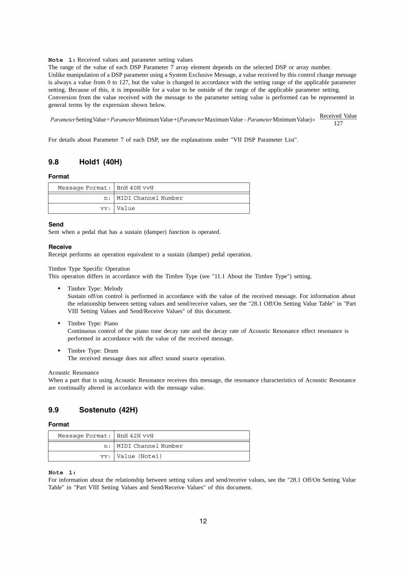
Note 1: Received values and parameter setting valuesThe range of the value of each DSP Parameter 7 array element depends on the selected DSP or array number.Unlike manipulation of a DSP parameter using a System Exclusive Message, a value received by this control change message is always a value from 0 to 127, but the value is changed in accordance with the setting range of the applicable parameter setting. Because of this, it is impossible for a value to be outside of the range of the applicable parameter setting.Conversion from the value received with the message to the parameter setting value is performed can be represented in general terms by the expression shown below.
For details about Parameter 7 of each DSP, see the explanations under "VII DSP Parameter List".
9.8 Hold1 (40H)
Format
SendSent when a pedal that has a sustain (damper) function is operated.
ReceiveReceipt performs an operation equivalent to a sustain (damper) pedal operation.
Timbre Type Specific OperationThis operation differs in accordance with the Timbre Type (see "11.1 About the Timbre Type") setting.
• Timbre Type: MelodySustain off/on control is performed in accordance with the value of the received message. For information about the relationship between setting values and send/receive values, see the "28.1 Off/On Setting Value Table" in "Part VIII Setting Values and Send/Receive Values" of this document.
• Timbre Type: PianoContinuous control of the piano tone decay rate and the decay rate of Acoustic Resonance effect resonance is performed in accordance with the value of the received message.
• Timbre Type: DrumThe received message does not affect sound source operation.
Acoustic ResonanceWhen a part that is using Acoustic Resonance receives this message, the resonance characteristics of Acoustic Resonance are continually altered in accordance with the message value.
9.9 Sostenuto (42H)
Format
Note 1:For information about the relationship between setting values and send/receive values, see the "28.1 Off/On Setting Value Table" in "Part VIII Setting Values and Send/Receive Values" of this document.
Parameter Setting Value = Parameter Minimum Value + (Parameter Maximum Value - Parameter Minimum Value) × Received Value127
Message Format: BnH 40H vvH
n: MIDI Channel Number
vv: Value
Message Format: BnH 42H vvH
n: MIDI Channel Number
vv: Value (Note1)
13
SendSent when a pedal that has a sostenuto function is operated.
ReceiveReceipt performs an operation equivalent to a sostenuto pedal operation.
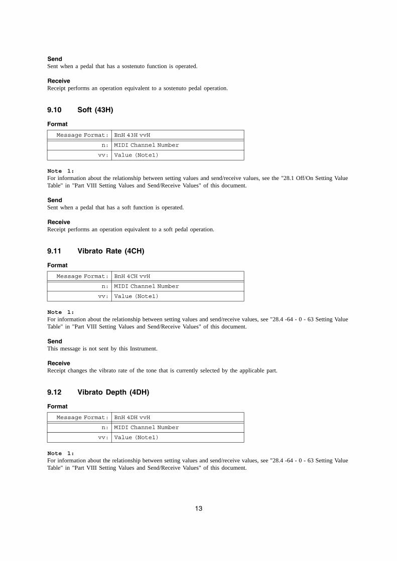
9.10 Soft (43H)
Format
Note 1:For information about the relationship between setting values and send/receive values, see the "28.1 Off/On Setting Value Table" in "Part VIII Setting Values and Send/Receive Values" of this document.
SendSent when a pedal that has a soft function is operated.
ReceiveReceipt performs an operation equivalent to a soft pedal operation.
9.11 Vibrato Rate (4CH)
Format
Note 1:For information about the relationship between setting values and send/receive values, see "28.4 -64 - 0 - 63 Setting Value Table" in "Part VIII Setting Values and Send/Receive Values" of this document.
SendThis message is not sent by this Instrument.
ReceiveReceipt changes the vibrato rate of the tone that is currently selected by the applicable part.
9.12 Vibrato Depth (4DH)
Format
Note 1:For information about the relationship between setting values and send/receive values, see "28.4 -64 - 0 - 63 Setting Value Table" in "Part VIII Setting Values and Send/Receive Values" of this document.
Message Format: BnH 43H vvH
n: MIDI Channel Number
vv: Value (Note1)
Message Format: BnH 4CH vvH
n: MIDI Channel Number
vv: Value (Note1)
Message Format: BnH 4DH vvH
n: MIDI Channel Number
vv: Value (Note1)
14
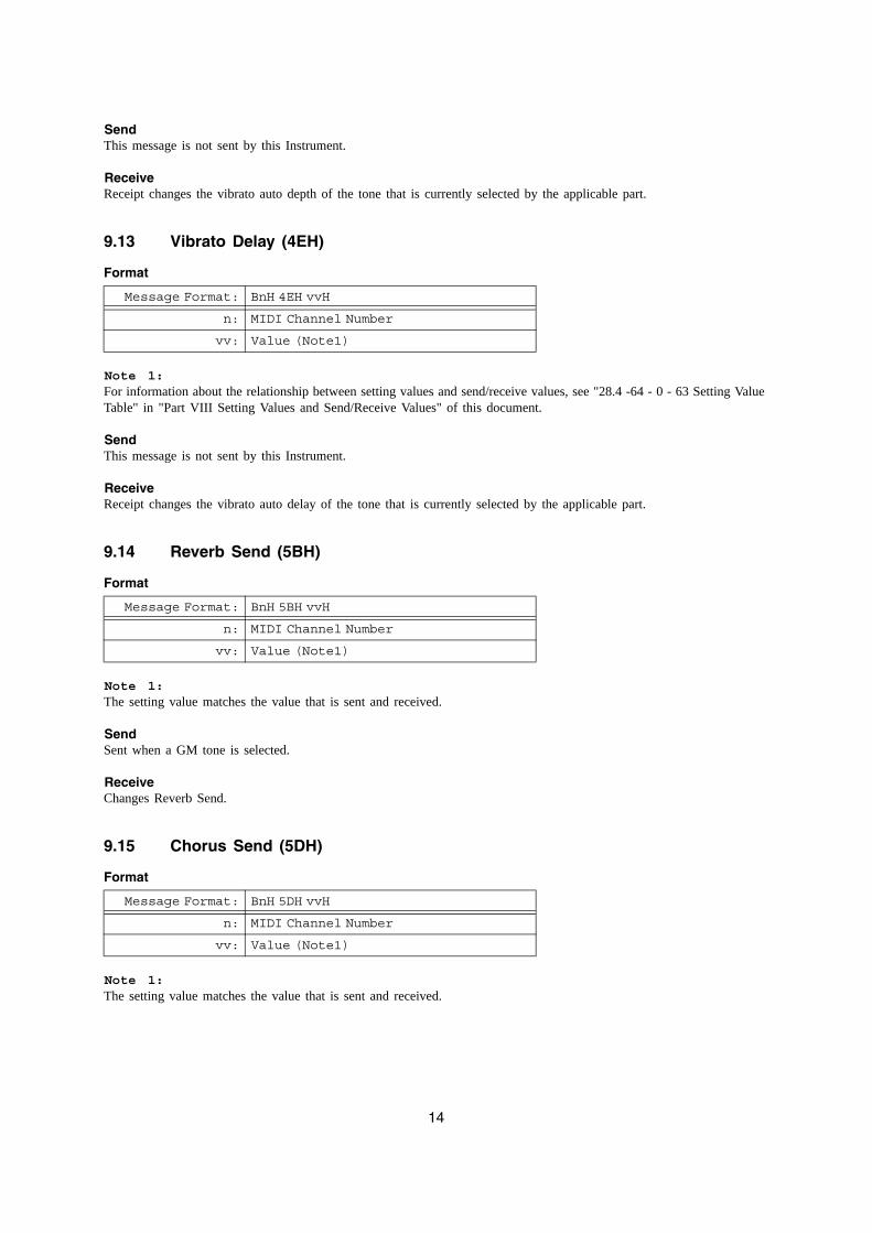
SendThis message is not sent by this Instrument.
ReceiveReceipt changes the vibrato auto depth of the tone that is currently selected by the applicable part.
9.13 Vibrato Delay (4EH)
Format
Note 1:For information about the relationship between setting values and send/receive values, see "28.4 -64 - 0 - 63 Setting Value Table" in "Part VIII Setting Values and Send/Receive Values" of this document.
SendThis message is not sent by this Instrument.
ReceiveReceipt changes the vibrato auto delay of the tone that is currently selected by the applicable part.
9.14 Reverb Send (5BH)
Format
Note 1:The setting value matches the value that is sent and received.
SendSent when a GM tone is selected.
ReceiveChanges Reverb Send.
9.15 Chorus Send (5DH)
Format
Note 1:The setting value matches the value that is sent and received.
Message Format: BnH 4EH vvH
n: MIDI Channel Number
vv: Value (Note1)
Message Format: BnH 5BH vvH
n: MIDI Channel Number
vv: Value (Note1)
Message Format: BnH 5DH vvH
n: MIDI Channel Number
vv: Value (Note1)
15
SendThis message is sent at initialization, when the panel tone selection is changed, and when a chorus on/off operation is performed.
ReceiveChanges Chorus Send.
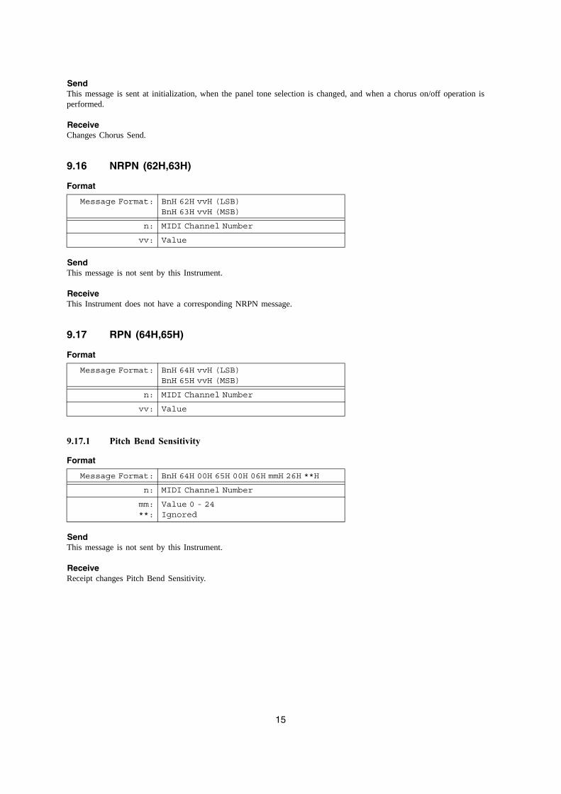
9.16 NRPN (62H,63H)
Format
SendThis message is not sent by this Instrument.
ReceiveThis Instrument does not have a corresponding NRPN message.
9.17 RPN (64H,65H)
Format
9.17.1 Pitch Bend Sensitivity
Format
SendThis message is not sent by this Instrument.
ReceiveReceipt changes Pitch Bend Sensitivity.
Message Format: BnH 62H vvH (LSB)BnH 63H vvH (MSB)
n: MIDI Channel Number
vv: Value
Message Format: BnH 64H vvH (LSB)BnH 65H vvH (MSB)
n: MIDI Channel Number
vv: Value
Message Format: BnH 64H 00H 65H 00H 06H mmH 26H **H
n: MIDI Channel Number
mm:**:
Value 0 - 24Ignored
16
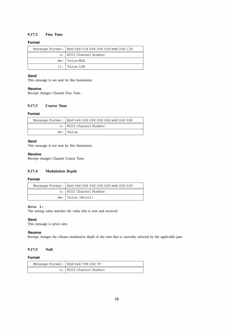
9.17.2 Fine Tune
Format
SendThis message is not sent by this Instrument.
ReceiveReceipt changes Channel Fine Tune.
9.17.3 Coarse Tune
Format
SendThis message is not sent by this Instrument.
ReceiveReceipt changes Channel Coarse Tune.
9.17.4 Modulation Depth
Format
Note 1:The setting value matches the value that is sent and received.
SendThis message is never sent.
ReceiveReceipt changes the vibrato modulation depth of the tone that is currently selected by the applicable part.
9.17.5 Null
Format
Message Format: BnH 64H 01H 65H 00H 06H mmH 26H llH
n: MIDI Channel Number
mm: Value MSB
ll: Value LSB
Message Format: BnH 64H 02H 65H 00H 06H mmH 26H 00H
n: MIDI Channel Number
mm: Value
Message Format: BnH 64H 05H 65H 00H 06H mmH 26H 00H
n: MIDI Channel Number
mm: Value (Note1)
Message Format: BnH 64H 7FH 65H 7F
n: MIDI Channel Number
17
SendThis message is never sent.
ReceiveReceipt deselects RPN.
9.18 All Sound Off (78H)
Format
SendSent when an SD memory card is inserted or removed, or when a memory card operation is performed.
ReceiveReceipt stops all voices that are sounding.
9.19 Reset All Controllers (79H)
Format
SendThis message is sent when the keyboard channel is changed and when the recorder function is used.
ReceiveReceipt initializes each performance controller.
10 Mode Message
10.1 All Notes Off (7BH)
Format
SendThis message is sent when a Music Library or recorder operation is performed.
ReceiveReceipt of any of this message releases the currently sounding voice (same as releasing the keyboard key).
Message Format: BnH 78H 00H
n: MIDI Channel Number
Message Format: BnH 79H 00H
n: MIDI Channel Number
Message Format: BnH 7BH 00H
n: MIDI Channel Number
18
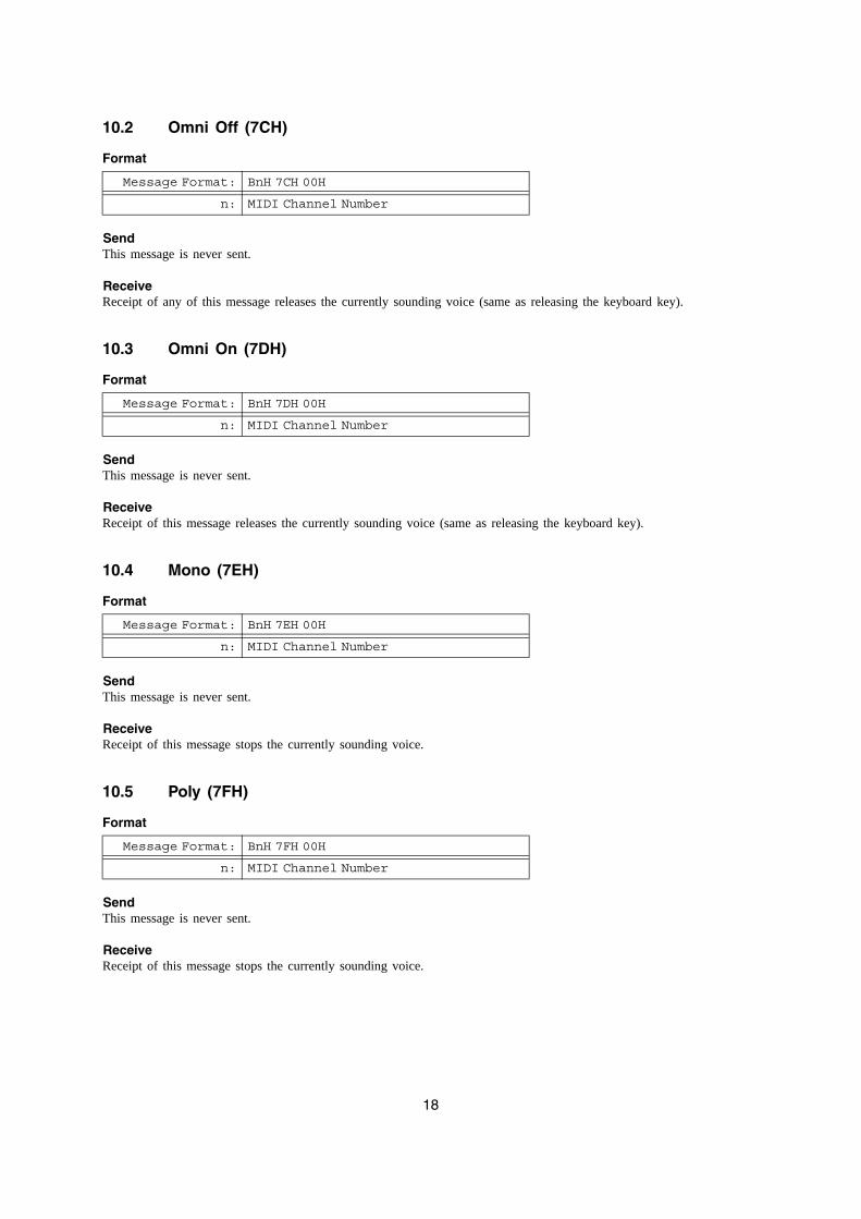
10.2 Omni Off (7CH)
Format
SendThis message is never sent.
ReceiveReceipt of any of this message releases the currently sounding voice (same as releasing the keyboard key).
10.3 Omni On (7DH)
Format
SendThis message is never sent.
ReceiveReceipt of this message releases the currently sounding voice (same as releasing the keyboard key).
10.4 Mono (7EH)
Format
SendThis message is never sent.
ReceiveReceipt of this message stops the currently sounding voice.
10.5 Poly (7FH)
Format
SendThis message is never sent.
ReceiveReceipt of this message stops the currently sounding voice.
Message Format: BnH 7CH 00H
n: MIDI Channel Number
Message Format: BnH 7DH 00H
n: MIDI Channel Number
Message Format: BnH 7EH 00H
n: MIDI Channel Number
Message Format: BnH 7FH 00H
n: MIDI Channel Number
19
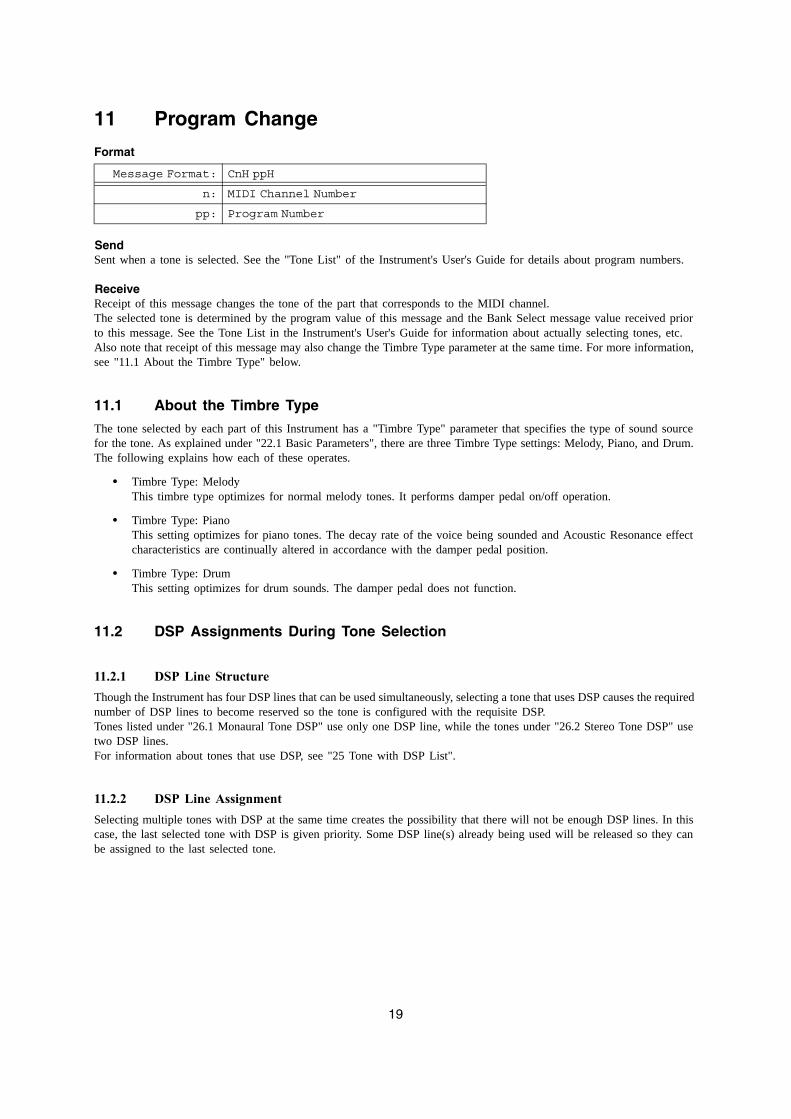
11 Program Change
Format
SendSent when a tone is selected. See the "Tone List" of the Instrument's User's Guide for details about program numbers.
ReceiveReceipt of this message changes the tone of the part that corresponds to the MIDI channel.The selected tone is determined by the program value of this message and the Bank Select message value received prior to this message. See the Tone List in the Instrument's User's Guide for information about actually selecting tones, etc.Also note that receipt of this message may also change the Timbre Type parameter at the same time. For more information, see "11.1 About the Timbre Type" below.
11.1 About the Timbre Type
The tone selected by each part of this Instrument has a "Timbre Type" parameter that specifies the type of sound source for the tone. As explained under "22.1 Basic Parameters", there are three Timbre Type settings: Melody, Piano, and Drum. The following explains how each of these operates.
• Timbre Type: MelodyThis timbre type optimizes for normal melody tones. It performs damper pedal on/off operation.
• Timbre Type: Piano This setting optimizes for piano tones. The decay rate of the voice being sounded and Acoustic Resonance effect characteristics are continually altered in accordance with the damper pedal position.
• Timbre Type: Drum This setting optimizes for drum sounds. The damper pedal does not function.
11.2 DSP Assignments During Tone Selection
11.2.1 DSP Line StructureThough the Instrument has four DSP lines that can be used simultaneously, selecting a tone that uses DSP causes the required number of DSP lines to become reserved so the tone is configured with the requisite DSP.Tones listed under "26.1 Monaural Tone DSP" use only one DSP line, while the tones under "26.2 Stereo Tone DSP" use two DSP lines.For information about tones that use DSP, see "25 Tone with DSP List".
11.2.2 DSP Line AssignmentSelecting multiple tones with DSP at the same time creates the possibility that there will not be enough DSP lines. In this case, the last selected tone with DSP is given priority. Some DSP line(s) already being used will be released so they can be assigned to the last selected tone.
Message Format: CnH ppH
n: MIDI Channel Number
pp: Program Number
20
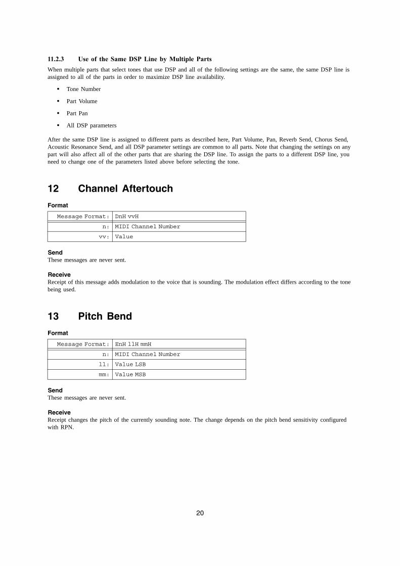
11.2.3 Use of the Same DSP Line by Multiple PartsWhen multiple parts that select tones that use DSP and all of the following settings are the same, the same DSP line is assigned to all of the parts in order to maximize DSP line availability.
• Tone Number
• Part Volume
• Part Pan
• All DSP parameters
After the same DSP line is assigned to different parts as described here, Part Volume, Pan, Reverb Send, Chorus Send, Acoustic Resonance Send, and all DSP parameter settings are common to all parts. Note that changing the settings on any part will also affect all of the other parts that are sharing the DSP line. To assign the parts to a different DSP line, you need to change one of the parameters listed above before selecting the tone.
12 Channel Aftertouch
Format
SendThese messages are never sent.
ReceiveReceipt of this message adds modulation to the voice that is sounding. The modulation effect differs according to the tone being used.
13 Pitch Bend
Format
SendThese messages are never sent.
ReceiveReceipt changes the pitch of the currently sounding note. The change depends on the pitch bend sensitivity configured with RPN.
Message Format: DnH vvH
n: MIDI Channel Number
vv: Value
Message Format: EnH llH mmH
n: MIDI Channel Number
ll: Value LSB
mm: Value MSB
21
Part III
System Messages
14 Active Sensing
Format
SendThis message is never sent.
ReceiveOnce this message is received, the Active Sensing mode is entered. If no MIDI message is received for a specified amount of time, voices being sounded by the Instrument's sound source are released, the controller is reset, and the Active Sensing mode is exited.
15 System Exclusive Message
Format
The Instrument sends and receives standard universal system exclusive messages, and system exclusive messages that have Instrument-specific formats.
15.1 Universal Realtime System Exclusive Message
Format
15.1.1 Master Volume
Format
Note 1:The setting value matches the value that is sent and received.
SendThis message is never sent.
ReceiveReceipt changes the Master Volume parameter. Note that the Master Volume parameter cannot be changed with an Instrument operation.
Message Format: FEH
Message Format: F0H....F7H
Message Format: F0H 7FH....F7H
Message Format: F0H 7FH 7FH 04H 01H llH mmH F7H
ll: Value LSB (Note1)
mm: Value MSB (Note1)
22
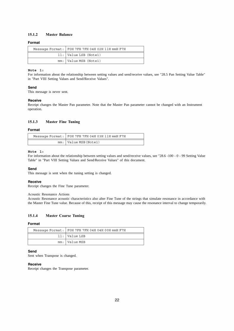
15.1.2 Master Balance
Format
Note 1:For information about the relationship between setting values and send/receive values, see "28.5 Pan Setting Value Table" in "Part VIII Setting Values and Send/Receive Values".
SendThis message is never sent.
ReceiveReceipt changes the Master Pan parameter. Note that the Master Pan parameter cannot be changed with an Instrument operation.
15.1.3 Master Fine Tuning
Format
Note 1:For information about the relationship between setting values and send/receive values, see "28.6 -100 - 0 - 99 Setting Value Table" in "Part VIII Setting Values and Send/Receive Values" of this document.
SendThis message is sent when the tuning setting is changed.
ReceiveReceipt changes the Fine Tune parameter.
Acoustic Resonance ActionsAcoustic Resonance acoustic characteristics also alter Fine Tune of the strings that simulate resonance in accordance with the Master Fine Tune value. Because of this, receipt of this message may cause the resonance interval to change temporarily.
15.1.4 Master Coarse Tuning
Format
SendSent when Transpose is changed.
ReceiveReceipt changes the Transpose parameter.
Message Format: F0H 7FH 7FH 04H 02H llH mmH F7H
ll: Value LSB (Note1)
mm: Value MSB (Note1)
Message Format: F0H 7FH 7FH 04H 03H llH mmH F7H
mm: Value MSB(Note1)
Message Format: F0H 7FH 7FH 04H 04H 00H mmH F7H
ll: Value LSB
mm: Value MSB
23
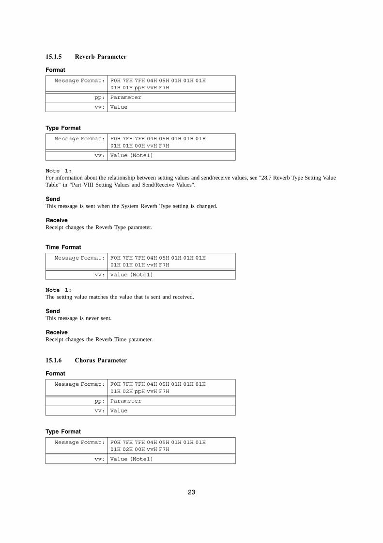
15.1.5 Reverb Parameter
Format
Type Format
Note 1:For information about the relationship between setting values and send/receive values, see "28.7 Reverb Type Setting Value Table" in "Part VIII Setting Values and Send/Receive Values".
SendThis message is sent when the System Reverb Type setting is changed.
ReceiveReceipt changes the Reverb Type parameter.
Time Format
Note 1:The setting value matches the value that is sent and received.
SendThis message is never sent.
ReceiveReceipt changes the Reverb Time parameter.
15.1.6 Chorus Parameter
Format
Type Format
Message Format: F0H 7FH 7FH 04H 05H 01H 01H 01H 01H 01H ppH vvH F7H
pp: Parameter
vv: Value
Message Format: F0H 7FH 7FH 04H 05H 01H 01H 01H 01H 01H 00H vvH F7H
vv: Value (Note1)
Message Format: F0H 7FH 7FH 04H 05H 01H 01H 01H 01H 01H 01H vvH F7H
vv: Value (Note1)
Message Format: F0H 7FH 7FH 04H 05H 01H 01H 01H 01H 02H ppH vvH F7H
pp: Parameter
vv: Value
Message Format: F0H 7FH 7FH 04H 05H 01H 01H 01H 01H 02H 00H vvH F7H
vv: Value (Note1)
24
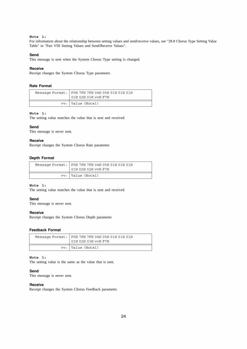
Note 1:For information about the relationship between setting values and send/receive values, see "28.8 Chorus Type Setting Value Table" in "Part VIII Setting Values and Send/Receive Values".
SendThis message is sent when the System Chorus Type setting is changed.
ReceiveReceipt changes the System Chorus Type parameter.
Rate Format
Note 1:The setting value matches the value that is sent and received.
SendThis message is never sent.
ReceiveReceipt changes the System Chorus Rate parameter.
Depth Format
Note 1:The setting value matches the value that is sent and received.
SendThis message is never sent.
ReceiveReceipt changes the System Chorus Depth parameter.
Feedback Format
Note 1:The setting value is the same as the value that is sent.
SendThis message is never sent.
ReceiveReceipt changes the System Chorus Feedback parameter.
Message Format: F0H 7FH 7FH 04H 05H 01H 01H 01H 01H 02H 01H vvH F7H
vv: Value (Note1)
Message Format: F0H 7FH 7FH 04H 05H 01H 01H 01H 01H 02H 02H vvH F7H
vv: Value (Note1)
Message Format: F0H 7FH 7FH 04H 05H 01H 01H 01H 01H 02H 03H vvH F7H
vv: Value (Note1)
25
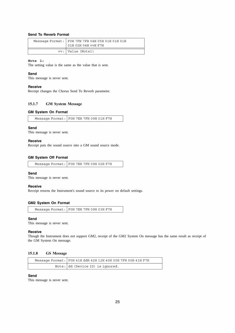
Send To Reverb Format
Note 1:The setting value is the same as the value that is sent.
SendThis message is never sent.
ReceiveReceipt changes the Chorus Send To Reverb parameter.
15.1.7 GM System Message
GM System On Format
SendThis message is never sent.
ReceiveReceipt puts the sound source into a GM sound source mode.
GM System Off Format
SendThis message is never sent.
ReceiveReceipt returns the Instrument's sound source to its power on default settings.
GM2 System On Format
SendThis message is never sent.
ReceiveThough the Instrument does not support GM2, receipt of the GM2 System On message has the same result as receipt of the GM System On message.
15.1.8 GS Message
SendThis message is never sent.
Message Format: F0H 7FH 7FH 04H 05H 01H 01H 01H 01H 02H 04H vvH F7H
vv: Value (Note1)
Message Format: F0H 7EH 7FH 09H 01H F7H
Message Format: F0H 7EH 7FH 09H 02H F7H
Message Format: F0H 7EH 7FH 09H 03H F7H
Message Format: F0H 41H ddH 42H 12H 40H 00H 7FH 00H 41H F7H
Note: dd (Device ID) is ignored.
26
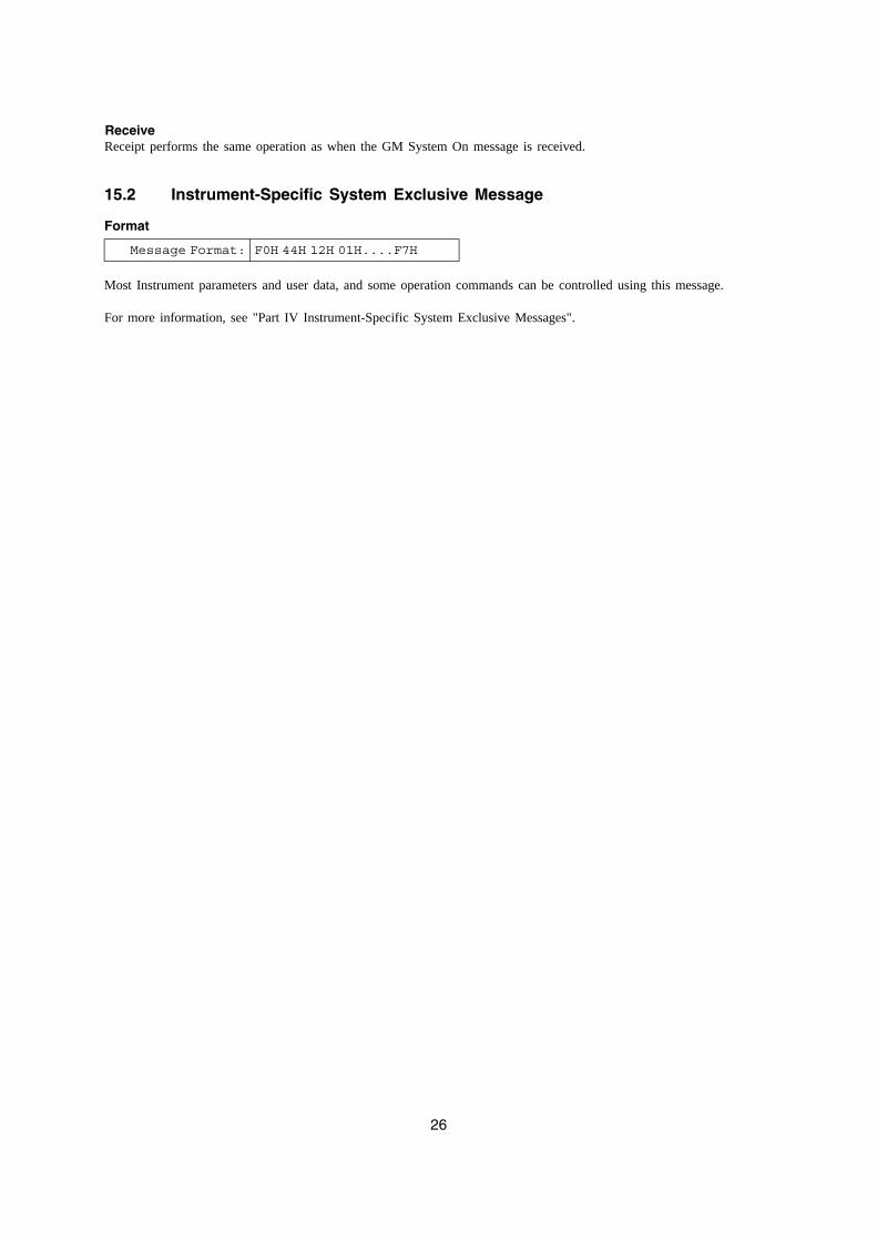
ReceiveReceipt performs the same operation as when the GM System On message is received.
15.2 Instrument-Specific System Exclusive Message
Format
Most Instrument parameters and user data, and some operation commands can be controlled using this message.
For more information, see "Part IV Instrument-Specific System Exclusive Messages".
Message Format: F0H 44H 12H 01H....F7H
27
Part IV
Instrument-Specific System Exclusive Messages
16 Format
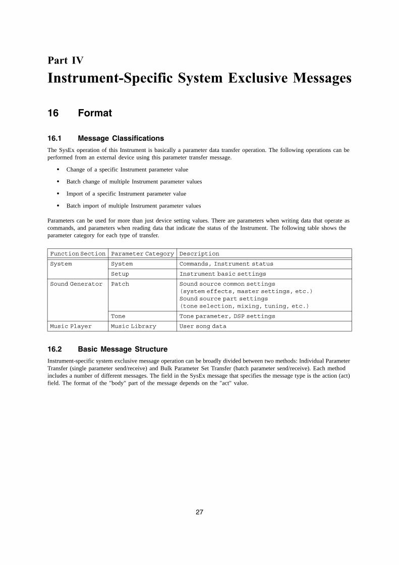
16.1 Message Classifications
The SysEx operation of this Instrument is basically a parameter data transfer operation. The following operations can be performed from an external device using this parameter transfer message.
• Change of a specific Instrument parameter value
• Batch change of multiple Instrument parameter values
• Import of a specific Instrument parameter value
• Batch import of multiple Instrument parameter values
Parameters can be used for more than just device setting values. There are parameters when writing data that operate as commands, and parameters when reading data that indicate the status of the Instrument. The following table shows the parameter category for each type of transfer.
16.2 Basic Message Structure
Instrument-specific system exclusive message operation can be broadly divided between two methods: Individual Parameter Transfer (single parameter send/receive) and Bulk Parameter Set Transfer (batch parameter send/receive). Each method includes a number of different messages. The field in the SysEx message that specifies the message type is the action (act) field. The format of the "body" part of the message depends on the "act" value.
Function Section Parameter Category Description
System System Commands, Instrument status
Setup Instrument basic settings
Sound Generator Patch Sound source common settings(system effects, master settings, etc.)Sound source part settings (tone selection, mixing, tuning, etc.)
Tone Tone parameter, DSP settings
Music Player Music Library User song data
28
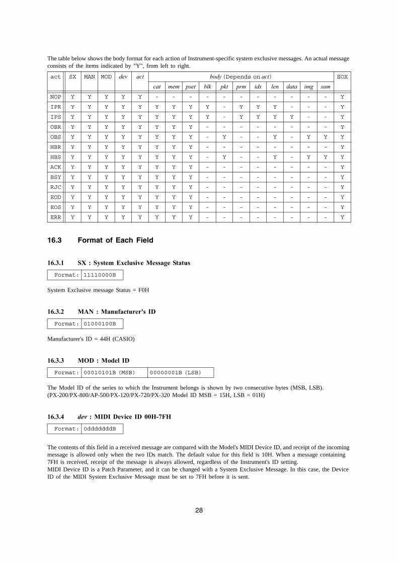
The table below shows the body format for each action of Instrument-specific system exclusive messages. An actual message consists of the items indicated by "Y", from left to right.
16.3 Format of Each Field
16.3.1 SX : System Exclusive Message Status
System Exclusive message Status = F0H
16.3.2 MAN : Manufacturer's ID
Manufacturer's ID = 44H (CASIO)
16.3.3 MOD : Model ID
The Model ID of the series to which the Instrument belongs is shown by two consecutive bytes (MSB, LSB).(PX-200/PX-800/AP-500/PX-120/PX-720/PX-320 Model ID MSB = 15H, LSB = 01H)
16.3.4 dev : MIDI Device ID 00H-7FH
The contents of this field in a received message are compared with the Model's MIDI Device ID, and receipt of the incoming message is allowed only when the two IDs match. The default value for this field is 10H. When a message containing 7FH is received, receipt of the message is always allowed, regardless of the Instrument's ID setting.MIDI Device ID is a Patch Parameter, and it can be changed with a System Exclusive Message. In this case, the Device ID of the MIDI System Exclusive Message must be set to 7FH before it is sent.
act SX MAN MOD dev act body (Depends on act) EOX
cat mem pset blk pkt prm idx len data img sum
NOP Y Y Y Y Y - - - - - - - - - - - Y
IPR Y Y Y Y Y Y Y Y Y - Y Y Y - - - Y
IPS Y Y Y Y Y Y Y Y Y - Y Y Y Y - - Y
OBR Y Y Y Y Y Y Y Y - - - - - - - - Y
OBS Y Y Y Y Y Y Y Y - Y - - Y - Y Y Y
HBR Y Y Y Y Y Y Y Y - - - - - - - - Y
HBS Y Y Y Y Y Y Y Y - Y - - Y - Y Y Y
ACK Y Y Y Y Y Y Y Y - - - - - - - - Y
BSY Y Y Y Y Y Y Y Y - - - - - - - - Y
RJC Y Y Y Y Y Y Y Y - - - - - - - - Y
EOD Y Y Y Y Y Y Y Y - - - - - - - - Y
EOS Y Y Y Y Y Y Y Y - - - - - - - - Y
ERR Y Y Y Y Y Y Y Y - - - - - - - - Y
Format: 11110000B
Format: 01000100B
Format: 00010101B (MSB) 00000001B (LSB)
Format: 0dddddddB
29
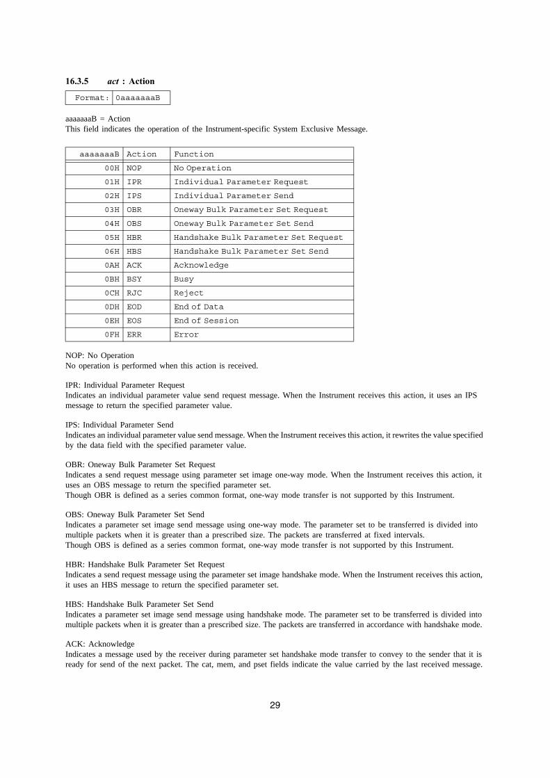
16.3.5 act : Action
aaaaaaaB = ActionThis field indicates the operation of the Instrument-specific System Exclusive Message.
NOP: No OperationNo operation is performed when this action is received.
IPR: Individual Parameter RequestIndicates an individual parameter value send request message. When the Instrument receives this action, it uses an IPS message to return the specified parameter value.
IPS: Individual Parameter SendIndicates an individual parameter value send message. When the Instrument receives this action, it rewrites the value specified by the data field with the specified parameter value.
OBR: Oneway Bulk Parameter Set RequestIndicates a send request message using parameter set image one-way mode. When the Instrument receives this action, it uses an OBS message to return the specified parameter set.Though OBR is defined as a series common format, one-way mode transfer is not supported by this Instrument.
OBS: Oneway Bulk Parameter Set SendIndicates a parameter set image send message using one-way mode. The parameter set to be transferred is divided into multiple packets when it is greater than a prescribed size. The packets are transferred at fixed intervals.Though OBS is defined as a series common format, one-way mode transfer is not supported by this Instrument.
HBR: Handshake Bulk Parameter Set RequestIndicates a send request message using the parameter set image handshake mode. When the Instrument receives this action, it uses an HBS message to return the specified parameter set.
HBS: Handshake Bulk Parameter Set SendIndicates a parameter set image send message using handshake mode. The parameter set to be transferred is divided into multiple packets when it is greater than a prescribed size. The packets are transferred in accordance with handshake mode.
ACK: AcknowledgeIndicates a message used by the receiver during parameter set handshake mode transfer to convey to the sender that it is ready for send of the next packet. The cat, mem, and pset fields indicate the value carried by the last received message.
Format: 0aaaaaaaB
aaaaaaaB Action Function
00H NOP No Operation
01H IPR Individual Parameter Request
02H IPS Individual Parameter Send
03H OBR Oneway Bulk Parameter Set Request
04H OBS Oneway Bulk Parameter Set Send
05H HBR Handshake Bulk Parameter Set Request
06H HBS Handshake Bulk Parameter Set Send
0AH ACK Acknowledge
0BH BSY Busy
0CH RJC Reject
0DH EOD End of Data
0EH EOS End of Session
0FH ERR Error
30
BSY: BusyIndicates a message to convey to the requester that that the Instrument cannot send back data after a parameter set one-way mode or handshake mode send request is received. The cat, mem, and pset fields indicate the value carried by the last received message.
RJC: RejectIndicates a message to convey to the other side that an ongoing parameter set one-way mode or handshake mode send or receive session was interrupted. The cat, mem, and pset fields indicate the value carried by the last received message.
EOD: End of DataIndicates a message to convey to the receiver that a one-way mode or handshake mode serial packet transfer for sending a sub-session (one parameter set) is complete. The cat, mem, and pset fields indicate the value carried by the last received message.
EOS: End of SessionIndicates a message to convey to the receiver that a one-way mode or handshake mode serial parameter set transfer session send, which was launched by some operation, is complete. The cat, mem, and pset fields indicate the value carried by the last received message.
ERR: ErrorIndicates a message to convey to the sender that the checksum or message format of the previous packet was not correct when receiving a parameter set with handshake mode. The cat, mem, and pset fields indicate the value carried by the last received message.
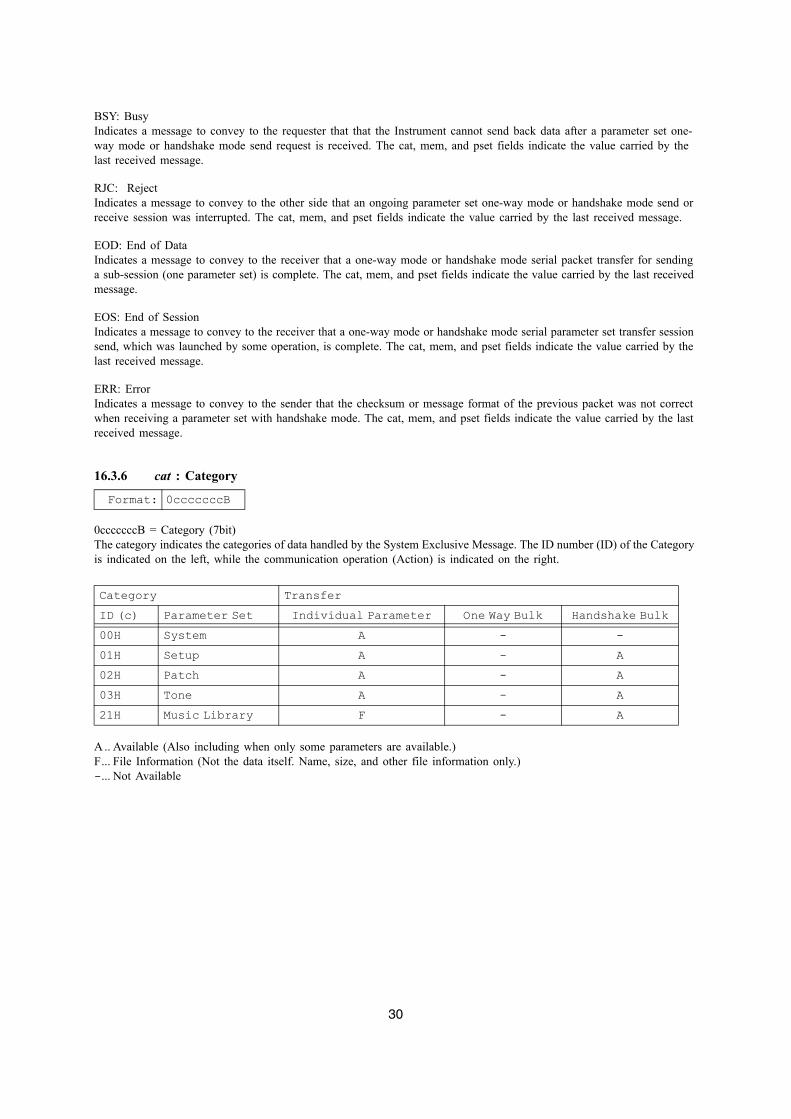
16.3.6 cat : Category
0cccccccB = Category (7bit)The category indicates the categories of data handled by the System Exclusive Message. The ID number (ID) of the Category is indicated on the left, while the communication operation (Action) is indicated on the right.
A .. Available (Also including when only some parameters are available.)F... File Information (Not the data itself. Name, size, and other file information only.)-... Not Available
Format: 0cccccccB
Category TransferID (c) Parameter Set Individual Parameter One Way Bulk Handshake Bulk00H System A - -01H Setup A - A02H Patch A - A03H Tone A - A21H Music Library F - A
31
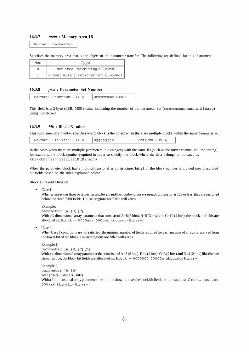
16.3.7 mem : Memory Area ID
Specifies the memory area that is the object of the parameter transfer. The following are defined for this Instrument.
16.3.8 pset : Parameter Set Number
This field is a 2-byte (LSB, MSB) value indicating the number of the parameter set (mmmmmmmnnnnnnnB, Binary) being transferred.
16.3.9 blk : Block NumberThis supplementary number specifies which block is the object when there are multiple blocks within the same parameter set.
In the cases when there are multiple parameters in a category with the same ID (such as the mixer channel volume setting), for example, the block number required in order to specify the block where the data belongs is indicated as kkkkkkkjjjjjjjiiiiiiiB (Binary).
When the parameter block has a multi-dimensional array structure, bit 21 of the block number is divided into prescribed bit fields based on the rules explained below.
Block Bit Field Division
• Case 1 When an array has three or fewer nesting levels and the number of arrays in each dimension is 128 or less, they are assigned below the three 7-bit fields. Unused regions are filled will zeros.
Example: parameter [A][B][C] With a 3-dimensional array parameter that consists of A=8 (3 bits), B=5 (3 bits) and C=10 (4 bits), the block bit fields are allocated as: Block = 0000aaa 000bbb ccccccc (Binary).
• Case 2 When Case 1 conditions are not satisfied, the minimal number of fields required for each number of arrays is reserved from the lower bit of the block. Unused regions are filled will zeros.
Example 1: parameter [A][B][C][D] With a 4-dimensional array parameter that consists of A=3 (2 bits), B=4 (2 bits), C=3 (2 bits) and D=4 (2 bits) like the one shown above, the block bit fields are allocated as: Block = 0000000 00000a abbccdd (Binary).
Example 2: parameter [A][B] A=3 (2 bits), B=200 (8 bits) With a 2-dimensional array parameter like the one shown above, the block bit fields are allocated as: Block = 0000000 000aab bbbbbbb (Binary).
Format: 0mmmmmmmB
Mem Type
0 User area (rewriting allowed)
1 Preset area (rewriting not allowed)
Format: 0nnnnnnnB (LSB) 0mmmmmmmB (MSB)
Format: 0iiiiiiiB (LSB) 0jjjjjjjB 0kkkkkkkB (MSB)
32
16.3.10 pkt : Packet Number
This is the divided packet number kkkkkkkjjjjjjjiiiiiiiB (Binary) for transferring a single parameter set.
16.3.11 prm : Parameter ID
The Parameter ID indicates the parameter type. When transferring parameters (see "Part V Parameter List" below) individually (as opposed to bulk transfer), this field is used to identify the parameter being transferred by its parameter ID.
16.3.12 idx : Data Index Number
The data index number indicates the first array number of the array from which transfer starts.
16.3.13 len : Data Length
Data length indicates the transfer array length minus 1 for individual parameter transfer when the parameter contains a character string or other similar array structure.In the case of bulk parameter set transfer, data length indicates the number of data words (16-bit data) included within a packet minus 1.
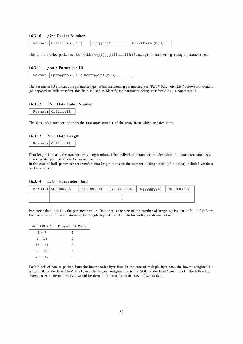
16.3.14 data : Parameter Data
Parameter data indicates the parameter value. Data that is the size of the number of arrays equivalent to len + 1 follows.For the structure of one data item, the length depends on the data bit width, as shown below.
Each block of data is packed from the lowest order byte first. In the case of multiple-byte data, the lowest weighted bit is the LSB of the first "data" block, and the highest weighted bit is the MSB of the final "data" block. The following shows an example of how data would be divided for transfer in the case of 32-bit data.
Format: 0iiiiiiiB (LSB) 0jjjjjjjB 0kkkkkkkB (MSB)
Format: 0pppppppB (LSB) 0qqqqqqqB (MSB)
Format: 0iiiiiiiB
Format: 0lllllllB
Format: 0dddddddB (0eeeeeeeB) (0fffffffB) (0gggggggB) (0hhhhhhhB)
::
dddddB + 1 Number of Data
1 - 7 1
8 - 14 2
15 - 21 3
22 - 28 4
29 - 32 5
33
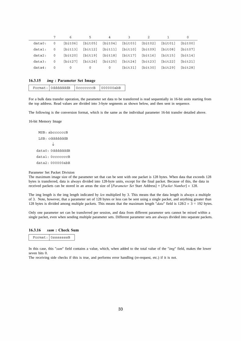
16.3.15 img : Parameter Set Image
For a bulk data transfer operation, the parameter set data to be transferred is read sequentially in 16-bit units starting from the top address. Read values are divided into 3-byte segments as shown below, and then sent in sequence.
The following is the conversion format, which is the same as the individual parameter 16-bit transfer detailed above.
16-bit Memory Image
Parameter Set Packet DivisionThe maximum image size of the parameter set that can be sent with one packet is 128 bytes. When data that exceeds 128 bytes is transferred, data is always divided into 128-byte units, except for the final packet. Because of this, the data in received packets can be stored in an areas the size of [Parameter Set Start Address] + [Packet Number] × 128.
The img length is the img length indicated by len multiplied by 3. This means that the data length is always a multiple of 3. Note, however, that a parameter set of 128 bytes or less can be sent using a single packet, and anything greater than 128 bytes is divided among multiple packets. This means that the maximum length "data" field is 128/2 × 3 = 192 bytes.
Only one parameter set can be transferred per session, and data from different parameter sets cannot be mixed within a single packet, even when sending multiple parameter sets. Different parameter sets are always divided into separate packets.
16.3.16 sum : Check Sum
In this case, this "sum" field contains a value, which, when added to the total value of the "img" field, makes the lower seven bits 0.The receiving side checks if this is true, and performs error handling (re-request, etc.) if it is not.
7 6 5 4 3 2 1 0
data0: 0 [bit06] [bit05] [bit04] [bit03] [bit02] [bit01] [bit00]
data1: 0 [bit13] [bit12] [bit11] [bit10] [bit09] [bit08] [bit07]
data2: 0 [bit20] [bit19] [bit18] [bit17] [bit16] [bit15] [bit14]
data3: 0 [bit27] [bit26] [bit25] [bit24] [bit23] [bit22] [bit21]
data4: 0 0 0 0 [bit31] [bit30] [bit29] [bit28]
Format: 0dddddddB 0cccccccB 000000abB
MSB: abccccccB
LSB: cdddddddB
↓
data0: 0dddddddB
data1: 0cccccccB
data2: 000000abB
Format: 0sssssssB
34
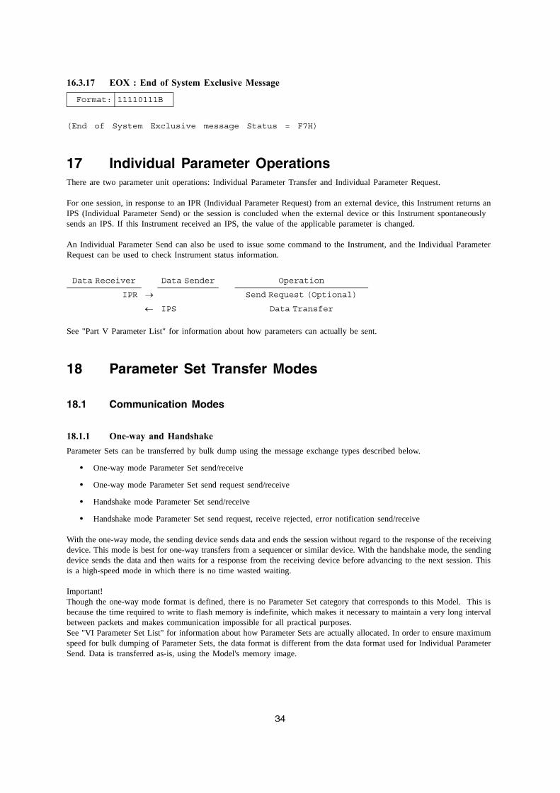
16.3.17 EOX : End of System Exclusive Message
(End of System Exclusive message Status = F7H)
17 Individual Parameter OperationsThere are two parameter unit operations: Individual Parameter Transfer and Individual Parameter Request.
For one session, in response to an IPR (Individual Parameter Request) from an external device, this Instrument returns an IPS (Individual Parameter Send) or the session is concluded when the external device or this Instrument spontaneously sends an IPS. If this Instrument received an IPS, the value of the applicable parameter is changed.
An Individual Parameter Send can also be used to issue some command to the Instrument, and the Individual Parameter Request can be used to check Instrument status information.
See "Part V Parameter List" for information about how parameters can actually be sent.
18 Parameter Set Transfer Modes
18.1 Communication Modes
18.1.1 One-way and HandshakeParameter Sets can be transferred by bulk dump using the message exchange types described below.
• One-way mode Parameter Set send/receive
• One-way mode Parameter Set send request send/receive
• Handshake mode Parameter Set send/receive
• Handshake mode Parameter Set send request, receive rejected, error notification send/receive
With the one-way mode, the sending device sends data and ends the session without regard to the response of the receiving device. This mode is best for one-way transfers from a sequencer or similar device. With the handshake mode, the sending device sends the data and then waits for a response from the receiving device before advancing to the next session. This is a high-speed mode in which there is no time wasted waiting.
Important!Though the one-way mode format is defined, there is no Parameter Set category that corresponds to this Model. This is because the time required to write to flash memory is indefinite, which makes it necessary to maintain a very long interval between packets and makes communication impossible for all practical purposes.See "VI Parameter Set List" for information about how Parameter Sets are actually allocated. In order to ensure maximum speed for bulk dumping of Parameter Sets, the data format is different from the data format used for Individual Parameter Send. Data is transferred as-is, using the Model's memory image.
Format: 11110111B
Data Receiver Data Sender Operation
IPR → Send Request (Optional)
← IPS Data Transfer
35
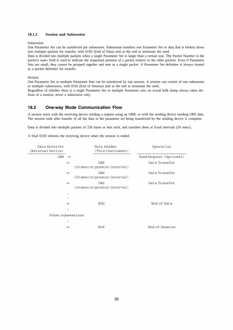
18.1.2 Session and Subsession
SubsessionOne Parameter Set can be transferred per subsession. Subsession transfers one Parameter Set or data that is broken down into multiple packets for transfer, with EOD (End of Data) sent at the end to terminate the send.Data is divided into multiple packets when a single Parameter Set is larger than a certain size. The Packet Number in the packet's index field is used to indicate the sequential position of a packet relative to the other packets. Even if Parameter Sets are small, they cannot be grouped together and sent as a single packet. A Parameter Set delimiter is always treated as a packet delimiter for transfer.
SessionOne Parameter Set or multiple Parameter Sets can be transferred by one session. A session can consist of one subsession or multiple subsessions, with EOS (End of Session) sent at the end to terminate the send.Regardless of whether there is a single Parameter Set or multiple Parameter sets, an actual bulk dump always takes the form of a session, never a subsession only.
18.2 One-way Mode Communication Flow
A session starts with the receiving device sending a request using an OBR, or with the sending device sending OBS data. The session ends after transfer of all the data in the parameter set being transferred by the sending device is complete.
Data is divided into multiple packets of 256 bytes or less each, and transfers them at fixed intervals (20 msec).
A final EOD informs the receiving device when the session is ended.
Data Receiver(External Device)
Data Sender(This Instrument)
Operation
OBR → Send Request (Optional)
← OBS(20 msec or greater interval)
Data Transfer
← OBS(20 msec or greater interval)
Data Transfer
← OBS(20 msec or greater interval)
Data Transfer
::
← EOD End of Data
:
Other subsessions
:
← EOS End of Session
36
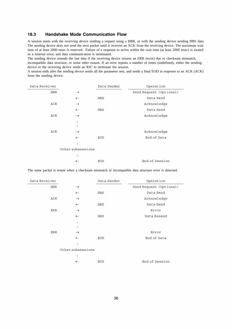
18.3 Handshake Mode Communication Flow
A session starts with the receiving device sending a request using a HBR, or with the sending device sending HBS data.The sending device does not send the next packet until it receives an ACK from the receiving device. The maximum wait time of at least 2000 msec is reserved. Failure of a response to arrive within the wait time (at least 2000 msec) is treated as a timeout error, and data communication is terminated.The sending device resends the last data if the receiving device returns an ERR (error) due to checksum mismatch, incompatible data structure, or some other reason. If an error repeats a number of times (undefined), either the sending device or the receiving device sends an RJC to terminate the session.A session ends after the sending device sends all the parameter sets, and sends a final EOD in response to an ACK (ACK) from the sending device.
The same packet is resent when a checksum mismatch or incompatible data structure error is detected.
Data Receiver Data Sender Operation
HBR → Send Request (Optional)
← HBS Data Send
ACK → Acknowledge
← HBS Data Send
ACK → Acknowledge
::
ACK → Acknowledge
← EOD End of Data
:
Other subsessions
:
← EOS End of Session
Data Receiver Data Sender Operation
HBR → Send Request (Optional)
← HBS Data Send
ACK → Acknowledge
← HBS Data Send
ERR → Error
← HBS Data Resend
::
ERR → Error
← EOD End of Data
:
Other subsessions
:
← EOS End of Session
37
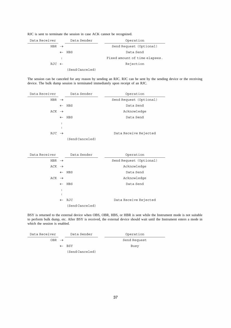
RJC is sent to terminate the session in case ACK cannot be recognized.
The session can be canceled for any reason by sending an RJC. RJC can be sent by the sending device or the receiving device. The bulk dump session is terminated immediately upon receipt of an RJC.
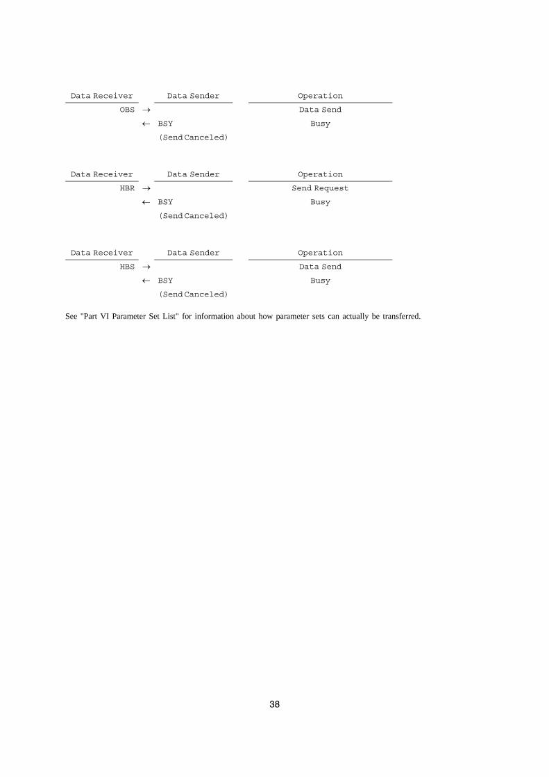
BSY is returned to the external device when OBS, OBR, HBS, or HBR is sent while the Instrument mode is not suitable to perform bulk dump, etc. After BSY is received, the external device should wait until the Instrument enters a mode in which the session is enabled.
Data Receiver Data Sender Operation
HBR → Send Request (Optional)
← HBS Data Send
: Fixed amount of time elapses.
RJC ← Rejection
(Send Canceled)
Data Receiver Data Sender Operation
HBR → Send Request (Optional)
← HBS Data Send
ACK → Acknowledge
← HBS Data Send
::
RJC → Data Receive Rejected
(Send Canceled)
Data Receiver Data Sender Operation
HBR → Send Request (Optional)
ACK → Acknowledge
← HBS Data Send
ACK → Acknowledge
← HBS Data Send
::
← RJC Data Receive Rejected
(Send Canceled)
Data Receiver Data Sender Operation
OBR → Send Request
← BSY Busy
(Send Canceled)
38
See "Part VI Parameter Set List" for information about how parameter sets can actually be transferred.
Data Receiver Data Sender Operation
OBS → Data Send
← BSY Busy
(Send Canceled)
Data Receiver Data Sender Operation
HBR → Send Request
← BSY Busy
(Send Canceled)
Data Receiver Data Sender Operation
HBS → Data Send
← BSY Busy
(Send Canceled)
39
Part V
Parameter List
How to Read the Tables
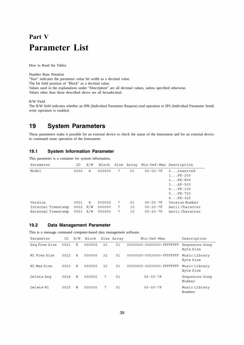
Number Base Notation "Size" indicates the parameter value bit width as a decimal value.The bit field position of "Block" as a decimal value.Values used in the explanations under "Description" are all decimal values, unless specified otherwise.Values other than those described above are all hexadecimal.
R/W FieldThe R/W field indicates whether an IPR (Individual Parameter Request) read operation or IPS (Individual Parameter Send) write operation is enabled.
19 System ParametersThese parameters make it possible for an external device to check the status of the Instrument and for an external device to command some operation of the Instrument.
19.1 System Information Parameter
This parameter is a container for system information.
19.2 Data Management Parameter
This is a message command computer-based data management software.
Parameter ID R/W Block Size Array Min-Def-Max Description
Model
VersionInternal TimestampExternal Timestamp
0000
000100020003
R
RR/WR/W
000000
000000000000000000
7
777
01
011010
00-00-7F
00-00-7F00-20-7F00-20-7F
0...reserved 1...PX-2002...PX-8003...AP-5004...PX-1205...PX-7206...PX-320Version NumberAscii CharacterAscii Character
Parameter ID R/W Block Size Array Min-Def-Max Description
Seq Free Size 0021 R 000000 32 01 00000000-00000000-FFFFFFFF Sequencer Song Byte Size
Ml Free Size 0022 R 000000 32 01 00000000-00030000-FFFFFFFF Music Library Byte Size
Ml Max Size 0023 R 000000 32 01 00000000-00030000-FFFFFFFF Music Library Byte Size
Delete Seq 0024 W 000000 7 01 00-00-7F Sequencer Song Number
Delete Ml 0025 W 000000 7 01 00-00-7F Music Library Number
40
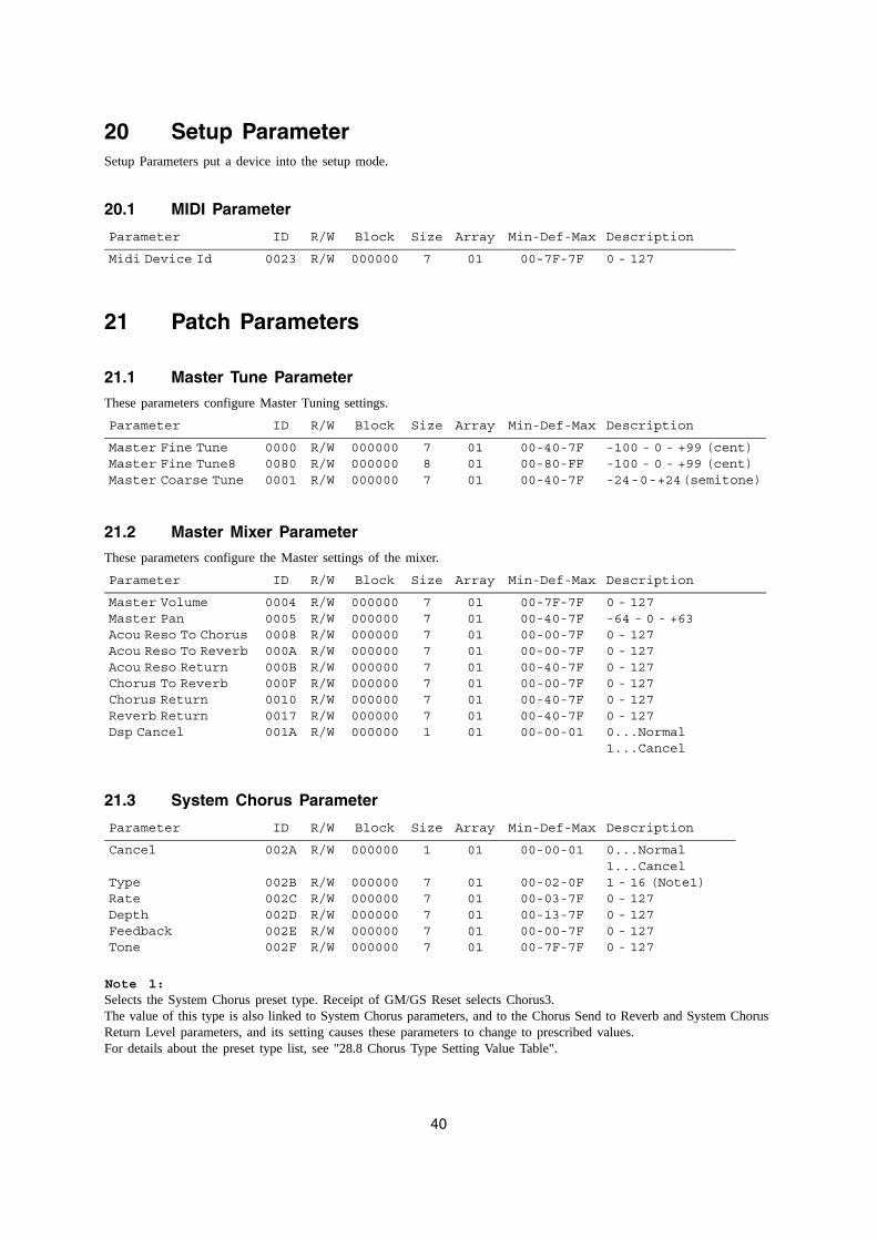
20 Setup ParameterSetup Parameters put a device into the setup mode.
20.1 MIDI Parameter
21 Patch Parameters
21.1 Master Tune Parameter
These parameters configure Master Tuning settings.
21.2 Master Mixer Parameter
These parameters configure the Master settings of the mixer.
21.3 System Chorus Parameter
Note 1:Selects the System Chorus preset type. Receipt of GM/GS Reset selects Chorus3.The value of this type is also linked to System Chorus parameters, and to the Chorus Send to Reverb and System Chorus Return Level parameters, and its setting causes these parameters to change to prescribed values.For details about the preset type list, see "28.8 Chorus Type Setting Value Table".
Parameter ID R/W Block Size Array Min-Def-Max Description
Midi Device Id 0023 R/W 000000 7 01 00-7F-7F 0 - 127
Parameter ID R/W Block Size Array Min-Def-Max Description
Master Fine TuneMaster Fine Tune8Master Coarse Tune
000000800001
R/WR/WR/W
000000000000000000
787
010101
00-40-7F00-80-FF00-40-7F
-100 - 0 - +99 (cent)-100 - 0 - +99 (cent)-24 - 0 - +24 (semitone)
Parameter ID R/W Block Size Array Min-Def-Max Description
Master VolumeMaster PanAcou Reso To ChorusAcou Reso To ReverbAcou Reso ReturnChorus To ReverbChorus ReturnReverb ReturnDsp Cancel
000400050008000A000B000F00100017001A
R/WR/WR/WR/WR/WR/WR/WR/WR/W
000000000000000000000000000000000000000000000000000000
777777771
010101010101010101
00-7F-7F00-40-7F00-00-7F00-00-7F00-40-7F00-00-7F00-40-7F00-40-7F00-00-01
0 - 127-64 - 0 - +630 - 1270 - 1270 - 1270 - 1270 - 1270 - 1270...Normal1...Cancel
Parameter ID R/W Block Size Array Min-Def-Max Description
Cancel
TypeRateDepthFeedbackTone
002A
002B002C002D002E002F
R/W
R/WR/WR/WR/WR/W
000000
000000000000000000000000000000
1
77777
01
0101010101
00-00-01
00-02-0F00-03-7F00-13-7F00-00-7F00-7F-7F
0...Normal1...Cancel1 - 16 (Note1)0 - 1270 - 1270 - 1270 - 127
41
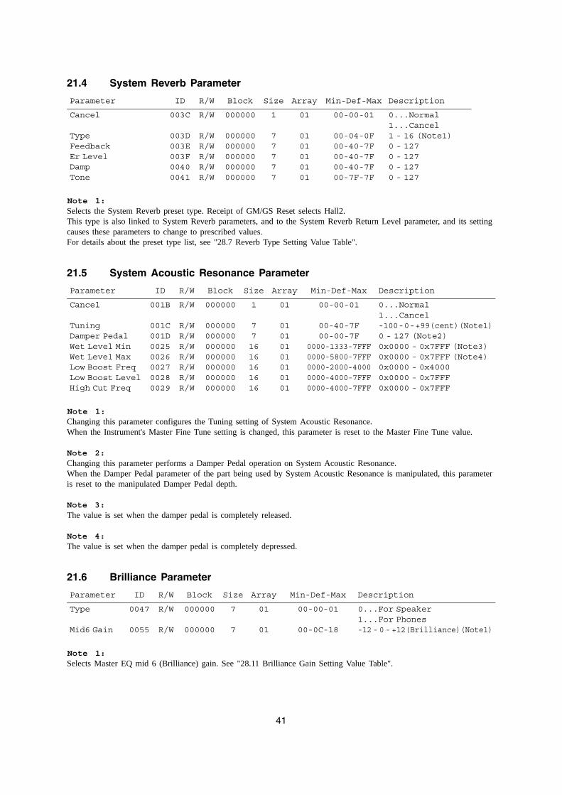
21.4 System Reverb Parameter
Note 1:Selects the System Reverb preset type. Receipt of GM/GS Reset selects Hall2.This type is also linked to System Reverb parameters, and to the System Reverb Return Level parameter, and its setting causes these parameters to change to prescribed values.For details about the preset type list, see "28.7 Reverb Type Setting Value Table".
21.5 System Acoustic Resonance Parameter
Note 1:Changing this parameter configures the Tuning setting of System Acoustic Resonance.When the Instrument's Master Fine Tune setting is changed, this parameter is reset to the Master Fine Tune value.
Note 2:Changing this parameter performs a Damper Pedal operation on System Acoustic Resonance.When the Damper Pedal parameter of the part being used by System Acoustic Resonance is manipulated, this parameter is reset to the manipulated Damper Pedal depth.
Note 3:The value is set when the damper pedal is completely released.
Note 4:The value is set when the damper pedal is completely depressed.
21.6 Brilliance Parameter
Note 1:Selects Master EQ mid 6 (Brilliance) gain. See "28.11 Brilliance Gain Setting Value Table".
Parameter ID R/W Block Size Array Min-Def-Max Description
Cancel
TypeFeedbackEr LevelDampTone
003C
003D003E003F00400041
R/W
R/WR/WR/WR/WR/W
000000
000000000000000000000000000000
1
77777
01
0101010101
00-00-01
00-04-0F00-40-7F00-40-7F00-40-7F00-7F-7F
0...Normal1...Cancel1 - 16 (Note1)0 - 1270 - 1270 - 1270 - 127
Parameter ID R/W Block Size Array Min-Def-Max Description
Cancel
TuningDamper PedalWet Level MinWet Level MaxLow Boost FreqLow Boost LevelHigh Cut Freq
001B
001C001D00250026002700280029
R/W
R/WR/WR/WR/WR/WR/WR/W
000000
000000000000000000000000000000000000000000
1
771616161616
01
01010101010101
00-00-01
00-40-7F00-00-7F
0000-1333-7FFF0000-5800-7FFF0000-2000-40000000-4000-7FFF0000-4000-7FFF
0...Normal1...Cancel-100 - 0 - +99(cent)(Note1)0 - 127 (Note2)0x0000 - 0x7FFF (Note3)0x0000 - 0x7FFF (Note4)0x0000 - 0x40000x0000 - 0x7FFF0x0000 - 0x7FFF
Parameter ID R/W Block Size Array Min-Def-Max Description
Type
Mid6 Gain
0047
0055
R/W
R/W
000000
000000
7
7
01
01
00-00-01
00-0C-18
0...For Speaker1...For Phones-12 - 0 - +12(Brilliance)(Note1)
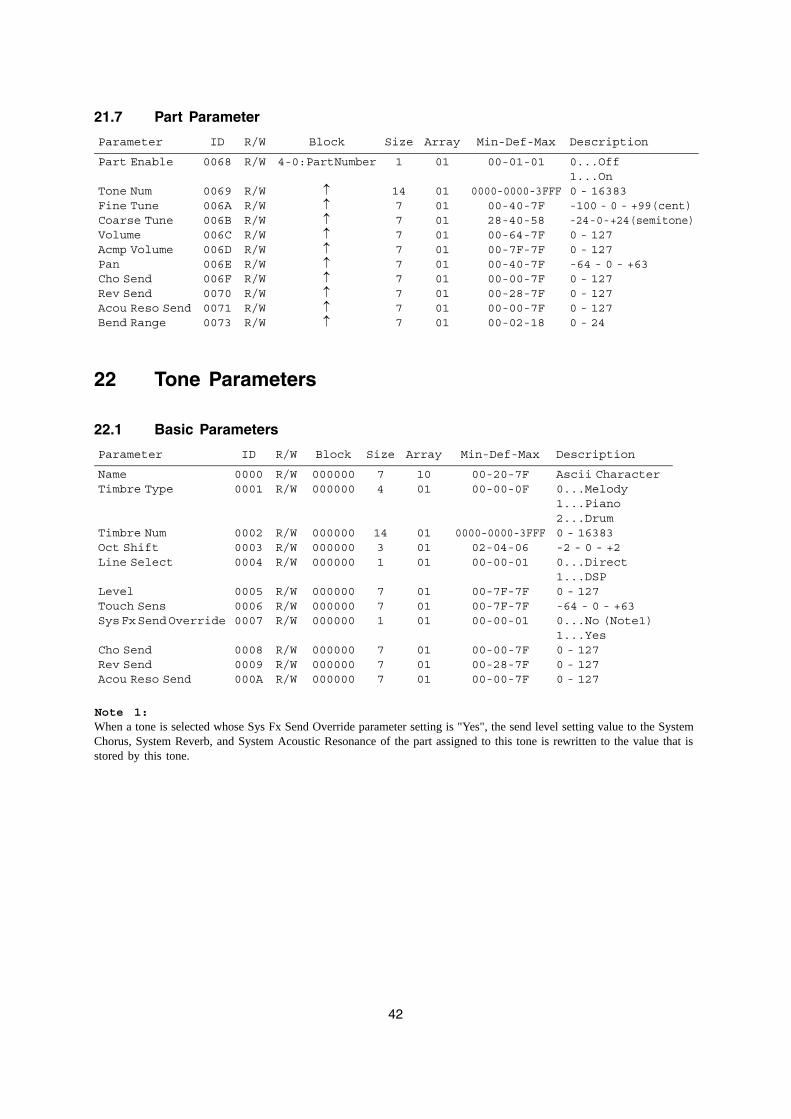
42
21.7 Part Parameter
22 Tone Parameters
22.1 Basic Parameters
Note 1:When a tone is selected whose Sys Fx Send Override parameter setting is "Yes", the send level setting value to the System Chorus, System Reverb, and System Acoustic Resonance of the part assigned to this tone is rewritten to the value that is stored by this tone.
Parameter ID R/W Block Size Array Min-Def-Max Description
Part Enable
Tone NumFine TuneCoarse TuneVolumeAcmp VolumePanCho SendRev SendAcou Reso SendBend Range
0068
0069006A006B006C006D006E006F007000710073
R/W
R/WR/WR/WR/WR/WR/WR/WR/WR/WR/W
4-0: Part Number
↑↑↑↑↑↑↑↑↑↑
1
14777777777
01
01010101010101010101
00-01-01
0000-0000-3FFF00-40-7F28-40-5800-64-7F00-7F-7F00-40-7F00-00-7F00-28-7F00-00-7F00-02-18
0...Off1...On0 - 16383-100 - 0 - +99(cent)-24 - 0 - +24(semitone)0 - 1270 - 127-64 - 0 - +630 - 1270 - 1270 - 1270 - 24
Parameter ID R/W Block Size Array Min-Def-Max Description
NameTimbre Type
Timbre NumOct ShiftLine Select
LevelTouch SensSys Fx Send Override
Cho SendRev SendAcou Reso Send
00000001
000200030004
000500060007
00080009000A
R/WR/W
R/WR/WR/W
R/WR/WR/W
R/WR/WR/W
000000000000
000000000000000000
000000000000000000
000000000000000000
74
1431
771
777
1001
010101
010101
010101
00-20-7F00-00-0F
0000-0000-3FFF02-04-0600-00-01
00-7F-7F00-7F-7F00-00-01
00-00-7F00-28-7F00-00-7F
Ascii Character0...Melody1...Piano2...Drum0 - 16383-2 - 0 - +20...Direct1...DSP0 - 127-64 - 0 - +630...No (Note1)1...Yes0 - 1270 - 1270 - 127
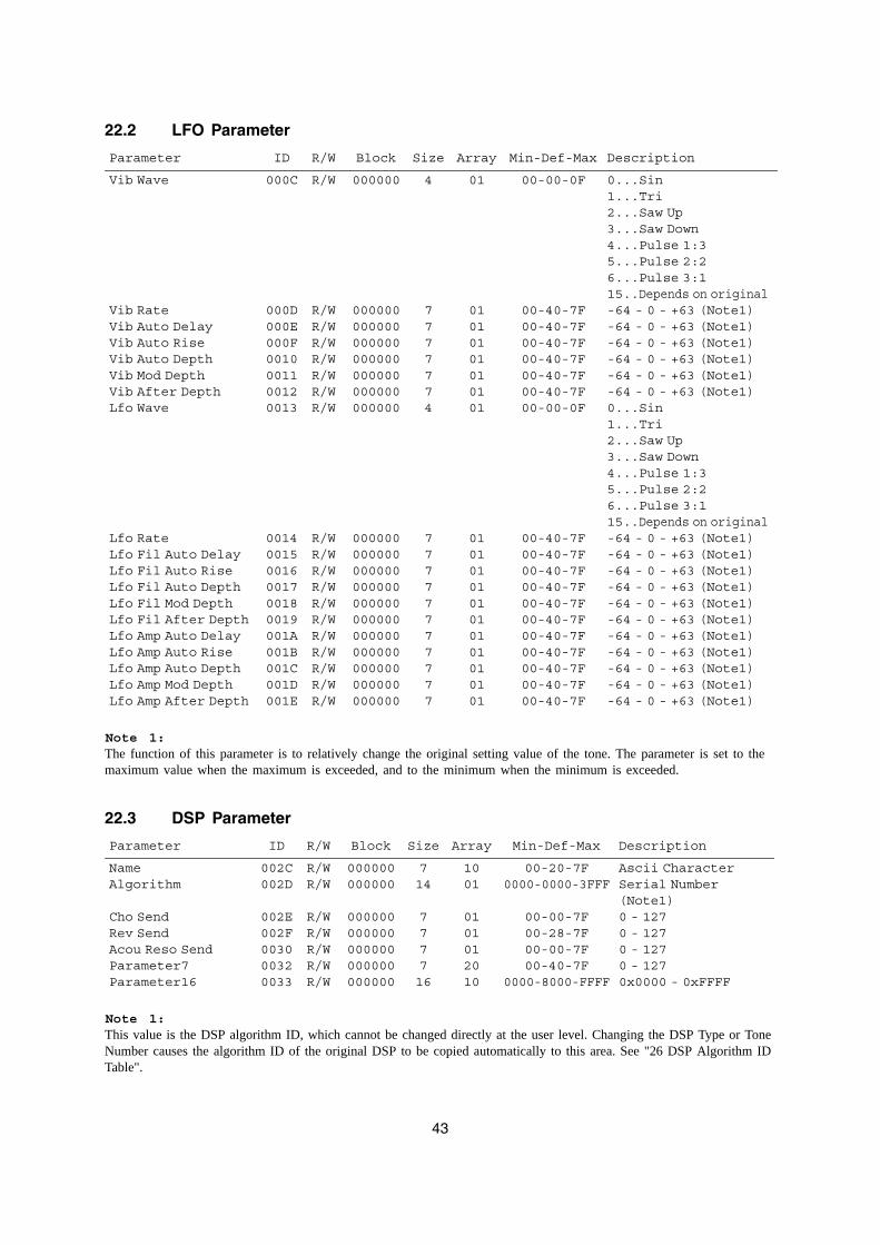
43
22.2 LFO Parameter
Note 1:The function of this parameter is to relatively change the original setting value of the tone. The parameter is set to the maximum value when the maximum is exceeded, and to the minimum when the minimum is exceeded.
22.3 DSP Parameter
Note 1:This value is the DSP algorithm ID, which cannot be changed directly at the user level. Changing the DSP Type or Tone Number causes the algorithm ID of the original DSP to be copied automatically to this area. See "26 DSP Algorithm ID Table".
Parameter ID R/W Block Size Array Min-Def-Max Description
Vib Wave
Vib RateVib Auto DelayVib Auto RiseVib Auto DepthVib Mod DepthVib After DepthLfo Wave
Lfo RateLfo Fil Auto DelayLfo Fil Auto RiseLfo Fil Auto DepthLfo Fil Mod DepthLfo Fil After DepthLfo Amp Auto DelayLfo Amp Auto RiseLfo Amp Auto DepthLfo Amp Mod DepthLfo Amp After Depth
000C
000D000E000F0010001100120013
001400150016001700180019001A001B001C001D001E
R/W
R/WR/WR/WR/WR/WR/WR/W
R/WR/WR/WR/WR/WR/WR/WR/WR/WR/WR/W
000000
000000000000000000000000000000000000000000
000000000000000000000000000000000000000000000000000000000000000000
4
7777774
77777777777
01
01010101010101
0101010101010101010101
00-00-0F
00-40-7F00-40-7F00-40-7F00-40-7F00-40-7F00-40-7F00-00-0F
00-40-7F00-40-7F00-40-7F00-40-7F00-40-7F00-40-7F00-40-7F00-40-7F00-40-7F00-40-7F00-40-7F
0...Sin1...Tri2...Saw Up3...Saw Down4...Pulse 1:35...Pulse 2:26...Pulse 3:115..Depends on original-64 - 0 - +63 (Note1)-64 - 0 - +63 (Note1)-64 - 0 - +63 (Note1)-64 - 0 - +63 (Note1)-64 - 0 - +63 (Note1)-64 - 0 - +63 (Note1)0...Sin1...Tri2...Saw Up3...Saw Down4...Pulse 1:35...Pulse 2:26...Pulse 3:115..Depends on original-64 - 0 - +63 (Note1)-64 - 0 - +63 (Note1)-64 - 0 - +63 (Note1)-64 - 0 - +63 (Note1)-64 - 0 - +63 (Note1)-64 - 0 - +63 (Note1)-64 - 0 - +63 (Note1)-64 - 0 - +63 (Note1)-64 - 0 - +63 (Note1)-64 - 0 - +63 (Note1)-64 - 0 - +63 (Note1)
Parameter ID R/W Block Size Array Min-Def-Max Description
NameAlgorithm
Cho SendRev SendAcou Reso SendParameter7Parameter16
002C002D
002E002F003000320033
R/WR/W
R/WR/WR/WR/WR/W
000000000000
000000000000000000000000000000
714
777716
1001
0101012010
00-20-7F0000-0000-3FFF
00-00-7F00-28-7F00-00-7F00-40-7F
0000-8000-FFFF
Ascii CharacterSerial Number(Note1)0 - 1270 - 1270 - 1270 - 1270x0000 - 0xFFFF
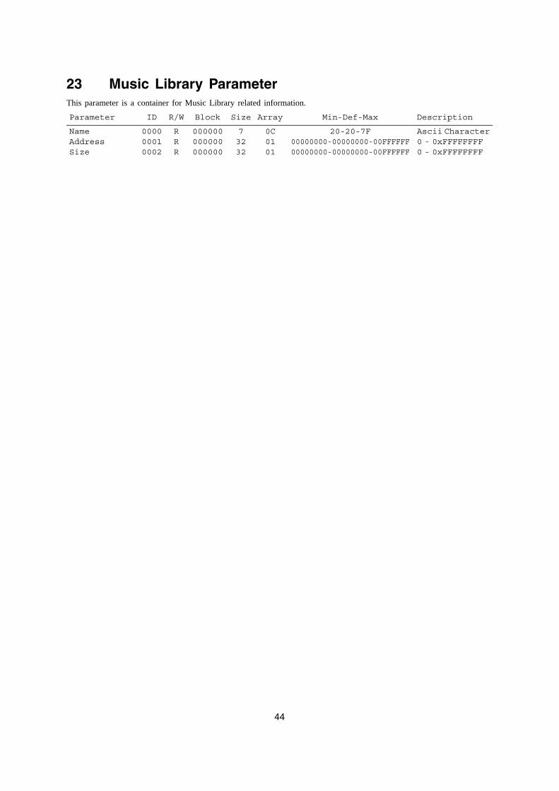
44
23 Music Library ParameterThis parameter is a container for Music Library related information.
Parameter ID R/W Block Size Array Min-Def-Max Description
NameAddressSize
000000010002
RRR
000000000000000000
73232
0C0101
20-20-7F00000000-00000000-00FFFFFF00000000-00000000-00FFFFFF
Ascii Character0 - 0xFFFFFFFF0 - 0xFFFFFFFF
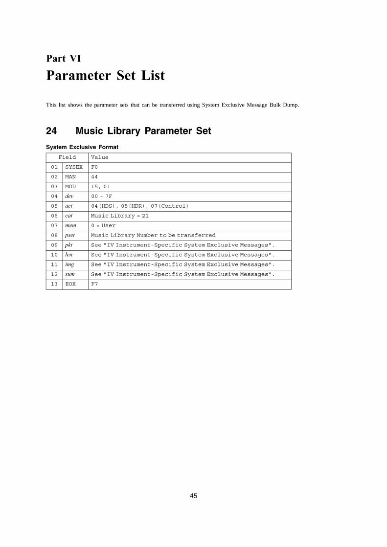
45
Part VI
Parameter Set List
This list shows the parameter sets that can be transferred using System Exclusive Message Bulk Dump.
24 Music Library Parameter Set
System Exclusive Format
Field Value
01 SYSEX F0
02 MAN 44
03 MOD 15, 01
04 dev 00 - 7F
05 act 04(HDS), 05(HDR), 07(Control)
06 cat Music Library = 21
07 mem 0 = User
08 pset Music Library Number to be transferred
09 pkt See "IV Instrument-Specific System Exclusive Messages".
10 len See "IV Instrument-Specific System Exclusive Messages".
11 img See "IV Instrument-Specific System Exclusive Messages".
12 sum See "IV Instrument-Specific System Exclusive Messages".
13 EOX F7
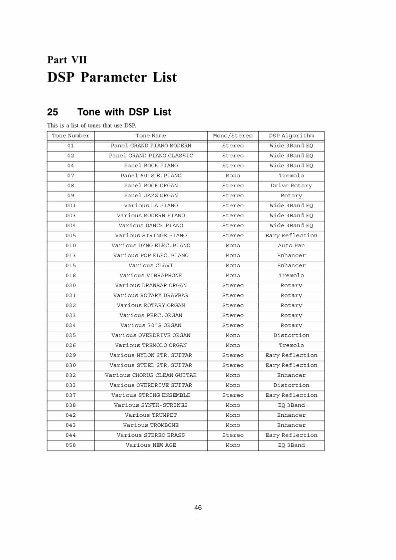
46
Part VII
DSP Parameter List
25 Tone with DSP ListThis is a list of tones that use DSP.
Tone Number Tone Name Mono/Stereo DSP Algorithm
01 Panel GRAND PIANO MODERN Stereo Wide 3Band EQ
02 Panel GRAND PIANO CLASSIC Stereo Wide 3Band EQ
04 Panel ROCK PIANO Stereo Wide 3Band EQ
07 Panel 60’S E.PIANO Mono Tremolo
08 Panel ROCK ORGAN Stereo Drive Rotary
09 Panel JAZZ ORGAN Stereo Rotary
001 Various LA PIANO Stereo Wide 3Band EQ
003 Various MODERN PIANO Stereo Wide 3Band EQ
004 Various DANCE PIANO Stereo Wide 3Band EQ
005 Various STRINGS PIANO Stereo Eary Reflection
010 Various DYNO ELEC.PIANO Mono Auto Pan
013 Various POP ELEC.PIANO Mono Enhancer
015 Various CLAVI Mono Enhancer
018 Various VIBRAPHONE Mono Tremolo
020 Various DRAWBAR ORGAN Stereo Rotary
021 Various ROTARY DRAWBAR Stereo Rotary
022 Various ROTARY ORGAN Stereo Rotary
023 Various PERC.ORGAN Stereo Rotary
024 Various 70’S ORGAN Stereo Rotary
025 Various OVERDRIVE ORGAN Mono Distortion
026 Various TREMOLO ORGAN Mono Tremolo
029 Various NYLON STR.GUITAR Stereo Eary Reflection
030 Various STEEL STR.GUITAR Stereo Eary Reflection
032 Various CHORUS CLEAN GUITAR Mono Enhancer
033 Various OVERDRIVE GUITAR Mono Distortion
037 Various STRING ENSEMBLE Stereo Eary Reflection
038 Various SYNTH-STRINGS Mono EQ 3Band
042 Various TRUMPET Mono Enhancer
043 Various TROMBONE Mono Enhancer
044 Various STEREO BRASS Stereo Eary Reflection
058 Various NEW AGE Mono EQ 3Band
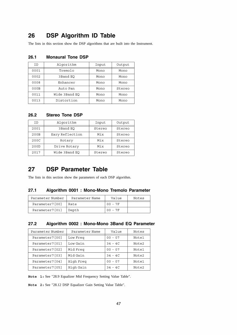
47
26 DSP Algorithm ID TableThe lists in this section show the DSP algorithms that are built into the Instrument.
26.1 Monaural Tone DSP
26.2 Stereo Tone DSP
27 DSP Parameter TableThe lists in this section show the parameters of each DSP algorithm.
27.1 Algorithm 0001 : Mono-Mono Tremolo Parameter
27.2 Algorithm 0002 : Mono-Mono 3Band EQ Parameter
Note 1: See "28.9 Equalizer Mid Frequency Setting Value Table".
Note 2: See "28.12 DSP Equalizer Gain Setting Value Table".
ID Algorithm Input Output
0001 Tremolo Mono Mono
0002 3Band EQ Mono Mono
0008 Enhancer Mono Mono
000B Auto Pan Mono Stereo
0011 Wide 3Band EQ Mono Mono
0013 Distortion Mono Mono
ID Algorithm Input Output
2001 3Band EQ Stereo Stereo
200B Eary Reflection Mix Stereo
200C Rotary Mix Stereo
200D Drive Rotary Mix Stereo
2017 Wide 3Band EQ Stereo Stereo
Parameter Number Parameter Name Value Notes
Parameter7[00] Rate 00 - 7F
Parameter7[01] Depth 00 - 7F
Parameter Number Parameter Name Value Notes
Parameter7[00] Low Freq 00 - 07 Note1
Parameter7[01] Low Gain 34 - 4C Note2
Parameter7[02] Mid Freq 00 - 07 Note1
Parameter7[03] Mid Gain 34 - 4C Note2
Parameter7[04] High Freq 00 - 07 Note1
Parameter7[05] High Gain 34 - 4C Note2
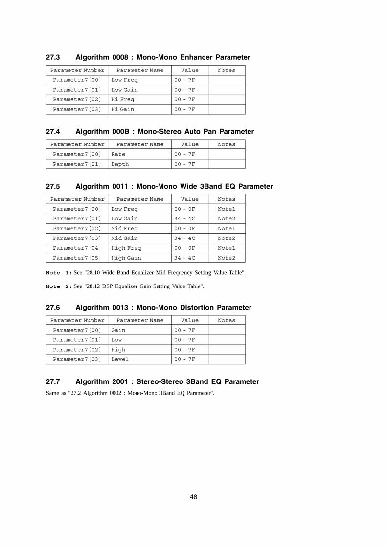
48
27.3 Algorithm 0008 : Mono-Mono Enhancer Parameter
27.4 Algorithm 000B : Mono-Stereo Auto Pan Parameter
27.5 Algorithm 0011 : Mono-Mono Wide 3Band EQ Parameter
Note 1: See "28.10 Wide Band Equalizer Mid Frequency Setting Value Table".
Note 2: See "28.12 DSP Equalizer Gain Setting Value Table".
27.6 Algorithm 0013 : Mono-Mono Distortion Parameter
27.7 Algorithm 2001 : Stereo-Stereo 3Band EQ Parameter
Same as "27.2 Algorithm 0002 : Mono-Mono 3Band EQ Parameter".
Parameter Number Parameter Name Value Notes
Parameter7[00] Low Freq 00 - 7F
Parameter7[01] Low Gain 00 - 7F
Parameter7[02] Hi Freq 00 - 7F
Parameter7[03] Hi Gain 00 - 7F
Parameter Number Parameter Name Value Notes
Parameter7[00] Rate 00 - 7F
Parameter7[01] Depth 00 - 7F
Parameter Number Parameter Name Value Notes
Parameter7[00] Low Freq 00 - 0F Note1
Parameter7[01] Low Gain 34 - 4C Note2
Parameter7[02] Mid Freq 00 - 0F Note1
Parameter7[03] Mid Gain 34 - 4C Note2
Parameter7[04] High Freq 00 - 0F Note1
Parameter7[05] High Gain 34 - 4C Note2
Parameter Number Parameter Name Value Notes
Parameter7[00] Gain 00 - 7F
Parameter7[01] Low 00 - 7F
Parameter7[02] High 00 - 7F
Parameter7[03] Level 00 - 7F
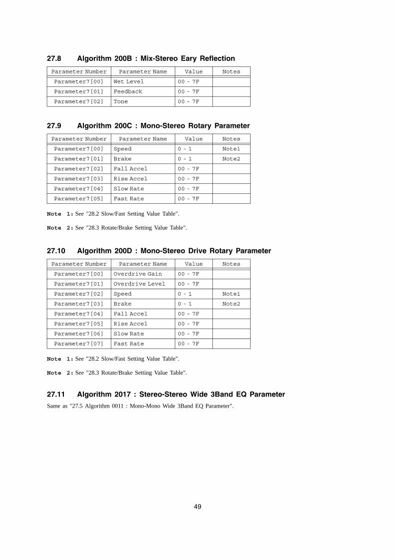
49
27.8 Algorithm 200B : Mix-Stereo Eary Reflection
27.9 Algorithm 200C : Mono-Stereo Rotary Parameter
Note 1: See "28.2 Slow/Fast Setting Value Table".
Note 2: See "28.3 Rotate/Brake Setting Value Table".
27.10 Algorithm 200D : Mono-Stereo Drive Rotary Parameter
Note 1: See "28.2 Slow/Fast Setting Value Table".
Note 2: See "28.3 Rotate/Brake Setting Value Table".
27.11 Algorithm 2017 : Stereo-Stereo Wide 3Band EQ Parameter
Same as "27.5 Algorithm 0011 : Mono-Mono Wide 3Band EQ Parameter".
Parameter Number Parameter Name Value Notes
Parameter7[00] Wet Level 00 - 7F
Parameter7[01] Feedback 00 - 7F
Parameter7[02] Tone 00 - 7F
Parameter Number Parameter Name Value Notes
Parameter7[00] Speed 0 - 1 Note1
Parameter7[01] Brake 0 - 1 Note2
Parameter7[02] Fall Accel 00 - 7F
Parameter7[03] Rise Accel 00 - 7F
Parameter7[04] Slow Rate 00 - 7F
Parameter7[05] Fast Rate 00 - 7F
Parameter Number Parameter Name Value Notes
Parameter7[00] Overdrive Gain 00 - 7F
Parameter7[01] Overdrive Level 00 - 7F
Parameter7[02] Speed 0 - 1 Note1
Parameter7[03] Brake 0 - 1 Note2
Parameter7[04] Fall Accel 00 - 7F
Parameter7[05] Rise Accel 00 - 7F
Parameter7[06] Slow Rate 00 - 7F
Parameter7[07] Fast Rate 00 - 7F
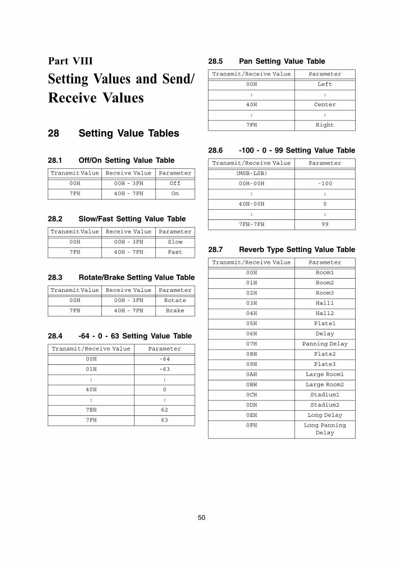
50
Part VIII
Setting Values and Send/Receive Values
28 Setting Value Tables
28.1 Off/On Setting Value Table
28.2 Slow/Fast Setting Value Table
28.3 Rotate/Brake Setting Value Table
28.4 -64 - 0 - 63 Setting Value Table
28.5 Pan Setting Value Table
28.6 -100 - 0 - 99 Setting Value Table
28.7 Reverb Type Setting Value Table
Transmit Value Receive Value Parameter
00H 00H - 3FH Off
7FH 40H - 7FH On
Transmit Value Receive Value Parameter
00H 00H - 3FH Slow
7FH 40H - 7FH Fast
Transmit Value Receive Value Parameter
00H 00H - 3FH Rotate
7FH 40H - 7FH Brake
Transmit/Receive Value Parameter
00H -64
01H -63
: :
40H 0
: :
7EH 62
7FH 63
Transmit/Receive Value Parameter
00H Left
: :
40H Center
: :
7FH Right
Transmit/Receive Value Parameter
(MSB-LSB)
00H-00H -100
: :
40H-00H 0
: :
7FH-7FH 99
Transmit/Receive Value Parameter
00H Room1
01H Room2
02H Room3
03H Hall1
04H Hall2
05H Plate1
06H Delay
07H Panning Delay
08H Plate2
09H Plate3
0AH Large Room1
0BH Large Room2
0CH Stadium1
0DH Stadium2
0EH Long Delay
0FH Long Panning Delay
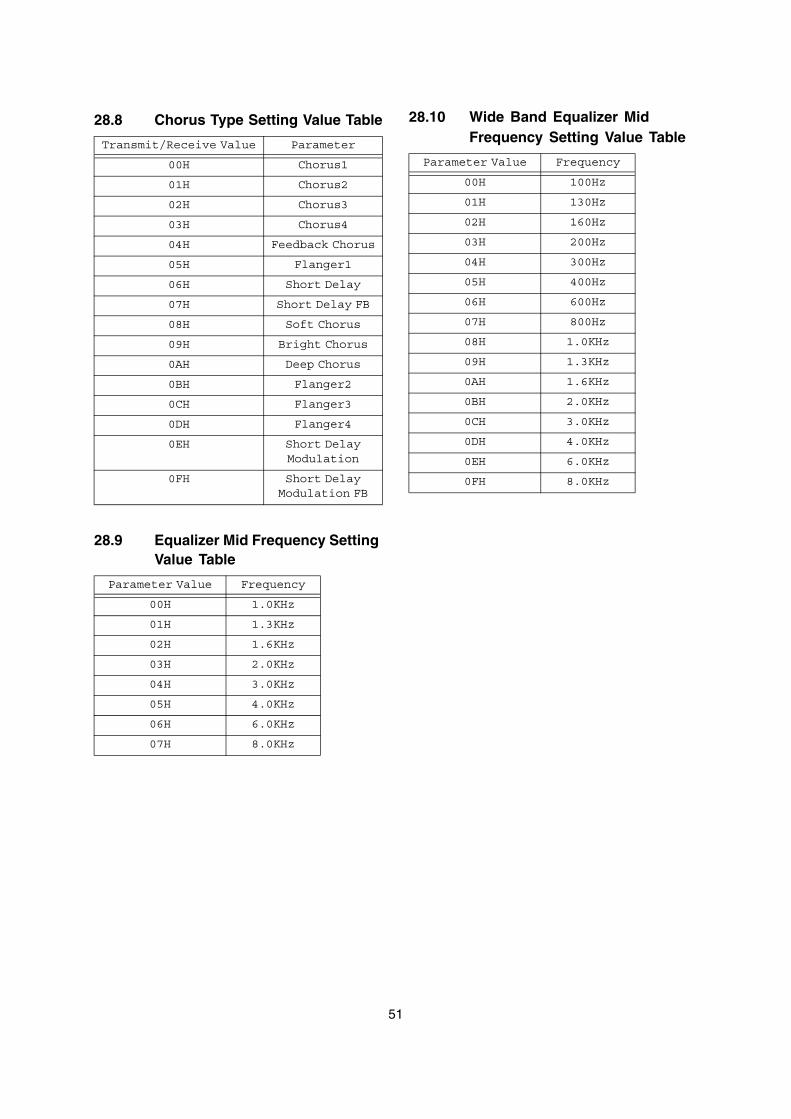
51
28.8 Chorus Type Setting Value Table
28.9 Equalizer Mid Frequency Setting Value Table
28.10 Wide Band Equalizer Mid Frequency Setting Value TableTransmit/Receive Value Parameter
00H Chorus1
01H Chorus2
02H Chorus3
03H Chorus4
04H Feedback Chorus
05H Flanger1
06H Short Delay
07H Short Delay FB
08H Soft Chorus
09H Bright Chorus
0AH Deep Chorus
0BH Flanger2
0CH Flanger3
0DH Flanger4
0EH Short Delay Modulation
0FH Short Delay Modulation FB
Parameter Value Frequency
00H 1.0KHz
01H 1.3KHz
02H 1.6KHz
03H 2.0KHz
04H 3.0KHz
05H 4.0KHz
06H 6.0KHz
07H 8.0KHz
Parameter Value Frequency
00H 100Hz
01H 130Hz
02H 160Hz
03H 200Hz
04H 300Hz
05H 400Hz
06H 600Hz
07H 800Hz
08H 1.0KHz
09H 1.3KHz
0AH 1.6KHz
0BH 2.0KHz
0CH 3.0KHz
0DH 4.0KHz
0EH 6.0KHz
0FH 8.0KHz
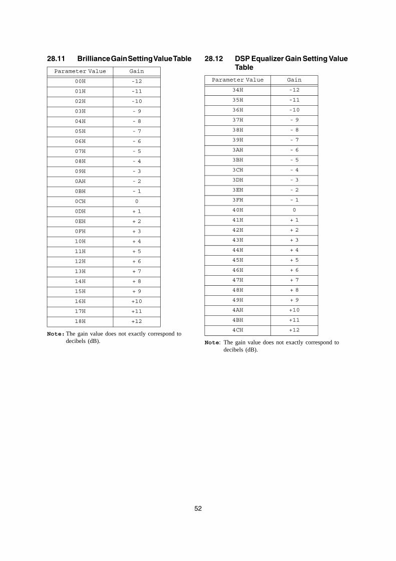
52
28.11 Brilliance Gain Setting Value Table
Note:The gain value does not exactly correspond to decibels (dB).
28.12 DSP Equalizer Gain Setting Value Table
Note: The gain value does not exactly correspond to decibels (dB).
Parameter Value Gain
00H -12
01H -11
02H -10
03H - 9
04H - 8
05H - 7
06H - 6
07H - 5
08H - 4
09H - 3
0AH - 2
0BH - 1
0CH 0
0DH + 1
0EH + 2
0FH + 3
10H + 4
11H + 5
12H + 6
13H + 7
14H + 8
15H + 9
16H +10
17H +11
18H +12
Parameter Value Gain
34H -12
35H -11
36H -10
37H - 9
38H - 8
39H - 7
3AH - 6
3BH - 5
3CH - 4
3DH - 3
3EH - 2
3FH - 1
40H 0
41H + 1
42H + 2
43H + 3
44H + 4
45H + 5
46H + 6
47H + 7
48H + 8
49H + 9
4AH +10
4BH +11
4CH +12
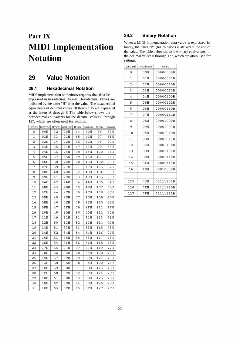
53
Part IX
MIDI Implementation Notation
29 Value Notation
29.1 Hexadecimal NotationMIDI implementation sometimes requires that data be expressed in hexadecimal format. Hexadecimal values are indicated by the letter "H" after the value. The hexadecimal equivalents of decimal values 10 through 15 are expressed as the letters A through F. The table below shows the hexadecimal equivalents for the decimal values 0 through 127, which are often used for settings.
29.2 Binary Notation
When a MIDI implementation data value is expressed in binary, the letter "B" (for "binary") is affixed at the end of the value. The table below shows the binary equivalents for the decimal values 0 through 127, which are often used for settings.
Decimal Hexadecimal Decimal Hexadecimal Decimal Hexadecimal Decimal Hexadecimal
0 00H 32 20H 64 40H 96 60H
1 01H 33 21H 65 41H 97 61H
2 02H 34 22H 66 42H 98 62H
3 03H 35 23H 67 43H 99 63H
4 04H 36 24H 68 44H 100 64H
5 05H 37 25H 69 45H 101 65H
6 06H 38 26H 70 46H 102 66H
7 07H 39 27H 71 47H 103 67H
8 08H 40 28H 72 48H 104 68H
9 09H 41 29H 73 49H 105 69H
10 0AH 42 2AH 74 4AH 106 6AH
11 0BH 43 2BH 75 4BH 107 6BH
12 0CH 44 2CH 76 4CH 108 6CH
13 0DH 45 2DH 77 4DH 109 6DH
14 0EH 46 2EH 78 4EH 110 6EH
15 0FH 47 2FH 79 4FH 111 6FH
16 10H 48 30H 80 50H 112 70H
17 11H 49 31H 81 51H 113 71H
18 12H 50 32H 82 52H 114 72H
19 13H 51 33H 83 53H 115 73H
20 14H 52 34H 84 54H 116 74H
21 15H 53 35H 85 55H 117 75H
22 16H 54 36H 86 56H 118 76H
23 17H 55 37H 87 57H 119 77H
24 18H 56 38H 88 58H 120 78H
25 19H 57 39H 89 59H 121 79H
26 1AH 58 3AH 90 5AH 122 7AH
27 1BH 59 3BH 91 5BH 123 7BH
28 1CH 60 3CH 92 5CH 124 7CH
29 1DH 61 3DH 93 5DH 125 7DH
30 1EH 62 3EH 94 5EH 126 7EH
31 1FH 63 3FH 95 5FH 127 7FH
Decimal Hexadecimal Binary
0 00H 00000000B
1 01H 00000001B
2 02H 00000010B
3 03H 00000011B
4 04H 00000100B
5 05H 00000101B
6 06H 00000110B
7 07H 00000111B
8 08H 00001000B
9 09H 00001001B
10 0AH 00001010B
11 0BH 00001011B
12 0CH 00001100B
13 0DH 00001101B
14 0EH 00001110B
15 0FH 00001111B
16 10H 00010000B
: :
125 7DH 01111101B
126 7EH 01111110B
127 7FH 01111111B

MA0710-A
CASIO COMPUTER CO.,LTD.6-2, Hon-machi 1-chome
Shibuya-ku, Tokyo 151-8543, Japan