py2n20 material properties and phase diagrams...py2n20 material properties and phase diagrams...
TRANSCRIPT

PY2N20-10
PY2N20
Material Properties and
Phase Diagrams
Lecture 10
P. Stamenov, PhD
School of Physics, TCD

Modern CMOS pair structure

Photolithographic Process

CMOS Processing Steps

Cu Damascene Process

6
• Bonding:
- Mostly ionic, some covalent.
- % ionic character increases with difference in
electronegativity.
Adapted from Fig. 2.7, Callister 7e. (Fig. 2.7 is adapted from Linus Pauling, The Nature of the Chemical
Bond, 3rd edition, Copyright 1939 and 1940, 3rd edition. Copyright 1960 by
Cornell University.
• Large vs small ionic bond character:
Ceramic Bonding
SiC: small
CaF2: large

7
Ceramic Crystal Structures
Oxide structures oxygen anions much larger than metal cations
close packed oxygen in a lattice (usually FCC)
cations in the holes of the oxygen lattice
often with direct relation between coordination
numbers and type of local environment
structures are often represented by mixed
polyhedral/atomic models
partial substitutions often lead to distortions of the
ideal structure
a few different elements can do similar tricks (Se,
Te, …)

8
Which sites will cations occupy?
Site Selection
1. Size of sites
– does the cation fit in the site
2. Stoichiometry
– if all of one type of site is full the
remainder have to go into other types of
sites.
3. Bond Hybridization

9
Ionic Bonding & Structure
1. Size - Stable structures:
-maximize the # of nearest oppositely charged neighbors.
Adapted from Fig. 12.1,
Callister 7e.
- -
- - +
unstable
• Charge Neutrality:
- Net charge in the
structure should
be zero.
- General form:
- -
- - +
stable
- -
- - +
stable
CaF 2 : Ca 2+
cation
F -
F -
anions +
A m X p
m, p determined by charge neutrality
10
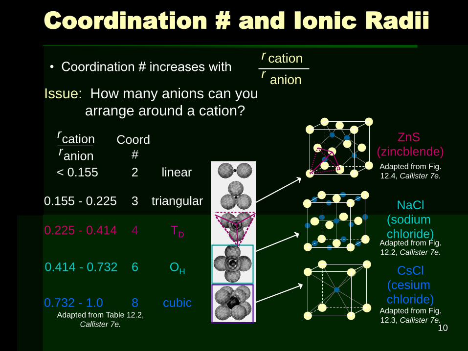
• Coordination # increases with
Coordination # and Ionic Radii
Adapted from Table 12.2,
Callister 7e.
2
r cation r anion
Coord
#
< 0.155
0.155 - 0.225
0.225 - 0.414
0.414 - 0.732
0.732 - 1.0
3
4
6
8
linear
triangular
TD
OH
cubic
Adapted from Fig.
12.2, Callister 7e.
Adapted from Fig.
12.3, Callister 7e.
Adapted from Fig.
12.4, Callister 7e.
ZnS (zincblende)
NaCl (sodium chloride)
CsCl (cesium chloride)
r cation
r anion Issue: How many anions can you
arrange around a cation?

11
Cation Site Size
Determine minimum rcation/ranion for OH site (C.N. = 6)
a = 2ranion
anion cation anion2 2 2 2r r r =
anion cation anion2r r r = cation anion( 2 1)r r=
anion cation2 2 2r r a =
4140anion
cation .r
r=

12
Site Selection II
2. Stoichiometry
If all of one type of site is full the remainder have to
go into other types of sites.
Ex: FCC unit cell has 4 OH and 8 TD sites.
If for a specific ceramic each unit cell has 6 cations
and the cations prefer OH sites
4 in OH
2 in TD

13
Site Selection III
3. Bond Hybridization – significant covalent bonding
the hybrid orbitals can have impact if significant
covalent bond character present
For example in SiC
XSi = 1.8 and XC = 2.5
2
Si C% character 100 {1-exp[-0.25( ) ]} 11.5%ionic X X= =
• ca. 89% covalent bonding
• both Si and C prefer sp3 hybridization
• Therefore in SiC get TD sites

14
• On the basis of ionic radii, what crystal structure
would you predict for FeO?
• Answer:
cation
anion
0.077
0.140
0.550
r
r=
=
based on this ratio,
- coord # = 6
- structure = NaCl
Data from Table 12.3,
Callister 7e.
Example: Predicting Structure of FeO
Ionic radius (nm)
0.053
0.077
0.069
0.100
0.140
0.181
0.133
Cation
Anion
Al 3+
Fe 2 +
Fe 3+
Ca 2+
O 2-
Cl -
F -

15
Rock Salt Structure
Same concepts can be applied to ionic solids in general.
Example: NaCl (rock salt) structure
rNa = 0.102 nm
rNa/rCl = 0.564
cations prefer OH sites
Adapted from Fig.
12.2, Callister 7e.
rCl = 0.181 nm

16
MgO and FeO
MgO and FeO also have the NaCl
structure O2- rO = 0.140 nm
Mg2+ rMg = 0.072 nm
rMg/rO = 0.514
cations prefer OH sites
So each oxygen has 6 neighboring Mg2+
Adapted from Fig.
12.2, Callister 7e.

17
AX Crystal Structures
AX–Type Crystal Structures include NaCl, CsCl, and zinc blende
Cs
Cl
0.1700.939
0.181
r
r
= =
Adapted from Fig.
12.3, Callister 7e.
Cesium Chloride structure:
cubic sites preferred
So each Cs+
has 8 neighboring Cl-

18
AX Crystal Structures
So each Zn2+
has 4 neighboring O2-
Zinc Blende structure
Adapted from Fig.
12.4, Callister 7e.
?? 529.0140.0
074.0
2
2
O
ZnHO
r
r==
• Size arguments predict Zn2+
in OH sites,
• In observed structure Zn2+
in TD sites
Why is Zn2+ in TD sites?
bonding hybridization of
zinc favors TD sites
Ex: ZnO, ZnS, SiC

19
AX2 Crystal Structures
Fluorite structure
• Calcium Fluorite (CaF2)
• cations in cubic sites
• UO2, ThO2, ZrO2, CeO2
• antifluorite structure –
cations and anions
reversed
Adapted from Fig.
12.5, Callister 7e.

20
ABX3 Crystal Structures
Perovskite Example:
complex oxide
BaTiO3
Adapted from Fig.
12.6, Callister 7e.

21
Mechanical Properties
We know that ceramics are more
brittle than metals. Why?
Consider method of deformation
slippage along slip planes
in ionic solids this slippage is very difficult
too much energy needed to move one
anion past another anion

22
Silicate Ceramics
Most common elements on earth are Si & O
SiO2 (silica) structures are quartz (trigonal),
crystobalite (tetragonal), & tridymite (hexagonal,
orthorhombic and monoclinic) – coesite, stishovite
and siefertite at high pressure and temperature
The strong Si-O bond leads to a strong, high melting
material (1710ºC)
Si4+
O2-
Adapted from Figs.
12.9-10, Callister 7e.
crystobalite

23
Amorphous Silica
Silica gels - amorphous SiO2
Si4+ and O2- not in well-ordered
lattice
Charge balanced by H+ (to form
OH-) at “dangling” bonds
very high surface area > 200 m2/g
SiO2 is quite stable, therefore
unreactive
makes good catalyst support
Adapted from Fig.
12.11, Callister 7e.

24
Silica Glass
Dense form of amorphous silica
Charge imbalance corrected with
“counter cations” such as Na+
Borosilicate glass is the pyrex glass
used in labs
better temperature stability & less brittle than sodium glass

25
• Frenkel Defect
- a cation is out of place.
• Shottky Defect
- a paired set of cation and anion vacancies.
• Equilibrium concentration of defects /~ DQ kTe
Adapted from Fig. 12.21, Callister
7e. (Fig. 12.21 is from W.G.
Moffatt, G.W. Pearsall, and J.
Wulff, The Structure and
Properties of Materials, Vol. 1,
Structure, John Wiley and Sons,
Inc., p. 78.)
Defects in Ceramic Structures
Shottky
Defect:
Frenkel
Defect

26
• Impurities must also satisfy charge balance = Electroneutrality
• Ex: NaCl
• Substitutional cation impurity
Impurities
Na + Cl -
initial geometry Ca 2+ impurity resulting geometry
Ca 2+
Na +
Na +
Ca 2+
cation vacancy
• Substitutional anion impurity
initial geometry O 2- impurity
O 2-
Cl -
an ion vacancy
Cl -
resulting geometry

27
Ceramic Phase Diagrams
MgO-Al2O3 diagram:
Adapted from Fig.
12.25, Callister 7e.