pyrolysis of palmoil residues in malaysia newsletters/pynews 19.pdf · pyrolysis of palm oil...
TRANSCRIPT
PyNe Contact details:
Co-ordinator: Tony BridgwaterTel: +44(0)121 204 3381Fax: +44(0)121 204 3680 Email: [email protected]
Newsletter/website administrator:
Emily Wakefield, Tel: +44(0)121 204 3420Fax: +44(0)121 204 3680Email: [email protected]: www.pyne.co.uk
By R.H. Venderbosch, E. Gansekoele, J.F. Florijn, D. Assink, BTG Biomass Technology Group B.V. and H.Y.Ng, Genting Bio-oil BHD
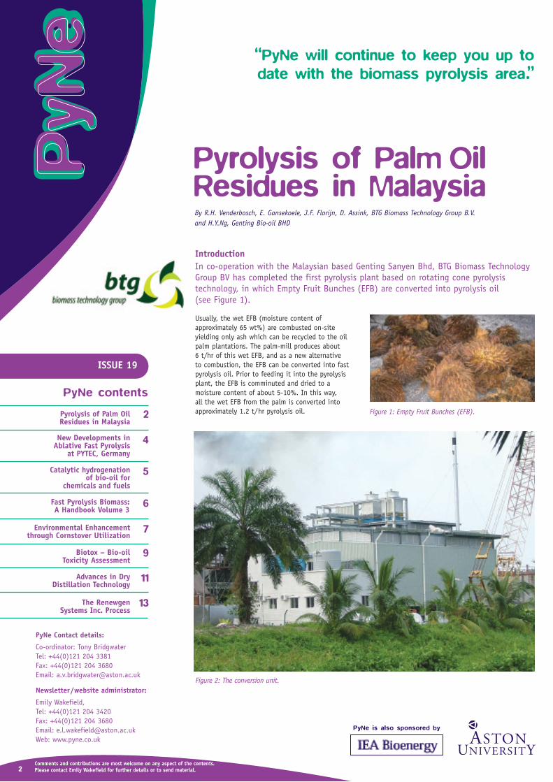
IntroductionIn co-operation with the Malaysian based Genting Sanyen Bhd, BTG Biomass TechnologyGroup BV has completed the first pyrolysis plant based on rotating cone pyrolysis technology, in which Empty Fruit Bunches (EFB) are converted into pyrolysis oil(see Figure 1).
Usually, the wet EFB (moisture content of approximately 65 wt%) are combusted on-site yielding only ash which can be recycled to the oilpalm plantations. The palm-mill produces about 6 t/hr of this wet EFB, and as a new alternative to combustion, the EFB can be converted into fastpyrolysis oil. Prior to feeding it into the pyrolysisplant, the EFB is comminuted and dried to a moisture content of about 5-10%. In this way,all the wet EFB from the palm is converted intoapproximately 1.2 t/hr pyrolysis oil.
Figure 2: The conversion unit.
Figure 1: Empty Fruit Bunches (EFB).
“PyNe will continue to keep you up to date with the biomass pyrolysis area.”
Comments and contributions are most welcome on any aspect of the contents.Please contact your country representative for further details or send material to Emily Wakefield.
2
Pyrolysis of Palm Oil Residues in Malaysia
2
New Developments in Ablative Fast Pyrolysis
at PYTEC, Germany
4
Catalytic hydrogenation of bio-oil for
chemicals and fuels
5
7Environmental Enhancement through Cornstover Utilization
Fast Pyrolysis Biomass:A Handbook Volume 3
6
Advances in Dry Distillation Technology
Biotox – Bio-oil Toxicity Assessment
11
9
The Renewgen Systems Inc. Process
13
2
ISSUE 19
PyNe contents
Comments and contributions are most welcome on any aspect of the contents.Please contact Emily Wakefield for further details or to send material.
Pyrolysis of Palm OilResidues in Malaysia
PyNe is also sponsored by

The pyrolysis plant was designed and built within 9 months in The Netherlands by BTG and Zeton. In January 2005 the plant was shipped to Malaysiaand re-assembled. From April 2005 onwards the pyrolysis plant has been extensively tested, modifiedand optimised. The main achievements were:
• Significant improvement in overall plant reliability, including pretreatment section.
• Production of first batches of good quality pyrolysis oil from the dry EFB.
• Significant improvement in pyrolysis oil quality,with respect to water content and ash content. A consistent oil is produced with a typical watercontent of about 25 wt%.
The project has now entered the final stage of commissioning.
Indications of pyrolysis investment costs range from 2 to 3 M€ for a 2 t/hr installation. This broad rangeof costs is a consequence of uncertainties in location,means of control, type of feedstock, etc. The highlyautomated plant can be operated by two (trained)persons. The electrical consumption is below 150 kWe,and principally, all this electricity can be generatedby the pyrolysis gas in an appropriate gas engine.Charcoal is used to supply the heat required by theplant. Additionally, it is expected that most of theheat for the drier can also be taken from the excessheat generated in the pyrolysis system.
Any party interested in green oil are welcome to talk with either BTG or Genting Bio-oil Sdn Bhdwww.genting.com about their specific requirements.Deliveries of varying amounts can be made, from small amounts of 10 litres up to 20 to 100 tons or more.
For further details contact:
R.H. VenderboschBiomass Technology Group BTGBusiness & Science ParkPantheon 12PS Enschede, 7521NetherlandsTel: +31 53 4886 2281Fax: +31 53 432 5399Email: [email protected]
3
Figure 3: Malaysian Pyrolysis Plant. Figure 4: Feedstock reception area.

4
New Developments inAblative Fast Pyrolysis atPYTEC, GermanyBy Dietrich Meier, BFH-Institute for Wood Chemistry, Germany; Stefan Schoell and Hannes Klaubert, PYTEC, Germany
IntroductionPYTEC Thermochemische Anlagen GmbH, Lüneburg, Germany, has installed the first fastpyrolysis plant in Germany operating with an ablative pyrolyser. Inauguration of the plantwas on 4th August 2005, with the Minister for Environment of Lower Saxony; Hannover inattendance, as his office is strongly supporting the pyrolysis project. Commissioning of theplant is envisaged for October 2005. Figure 1 shows an overall view of the new PYTEC site.
Figure 1: The PYTEC site.
Figure 2: Feed bin and drum dryer.
Figure 3: Insulated disc compartment.
Figure 4: CHP plant.
Figure 5: Mercedes Engine.
The plant is designed for 6 tonnes per day throughput of normal wood chips without prior grinding. Figure 2 shows the feed bin (blue container) and below the drum dryer. The chips fall from the top bin into the dryer and are thentransported via a conveyor to the top of the pyrolyser where they enter the compactor unit. From here the chips are hydraulically pressed againsta heated rotating disk which forms the heart of theplant. Figure 3 shows the insulated disc compartment. After collection and storage of the bio-oil it is burnt in the CHP plant (see Figure 4).
The special feature of the plant is that all system components are placed in standard containers in order to facilitate authorisation, transportation and assembly. The pyrolysis plant is erected at a saw millsite in Bülkau (near Cuxhaven, North Germany) whichis producing roughly 100 tonnes per day of untreatedwaste wood chips.
An important milestone was reached by PYTEC inDecember 2004, when they continuously operated amodified 12 cylinder Mercedes-Benz CHP diesel engineon bio-oil for 12 hours (Figure 5). Only 4 vol.% offossil diesel fuel was added. The bio-oil was deliveredby FORTUM, Finland, and produced in their Forestera®plant. During the smooth engine operation, ca. 3 MWelectricity (300-320 kWel/h) were produced and fedinto the grid. No fouling of the motor parts could beobserved. These results encouraged PYTEC to installthe same CHP-type system at their ablative pyrolyserplant in Bülkau.
For further details contact:
Mr Stefan Schoell (Manager)Mr Hannes Klaubert (Engineer)PytecBahnhofstr. 7, D-21337 LüneburgGermanyTel: +49 (0)40 734 30 808Email: [email protected]: www.pytecsite.com

Project Summary:Utilising the expertise developed in the earlier work,the research in this area since 2003 has involvedtesting innovative metal catalysts designed for usewith the high-moisture environment of bio-oil. The combination of these catalysts with processingconditions better suited to bio-oil has led to newproduct slates through upgrading both whole bio-oil(from different biomasses and biorefinery residue, i.e. bagasse) and bio-oil fractions, such as pyrolyticlignin. Specifically, the project involves the processdevelopment of enabling technology for catalytichydrogenation for converting bio-oil to value-addedproducts. Basic chemistry studies are underway inbench-scale reactor systems to better understand catalytic effects on chemical mechanisms and kinetics for upgrading. Initial results have identifiedproduct fractions, which have value as chemical products, e.g. cyclohexanols and phenolics. In some cases, the product slates have properties moreapplicable to conventional petroleum refining operations. Specifically, such products were testedand found to be useful feedstock in conventionalhydrocracking technology for production of hydrocarbon product streams.
Project Strategy:The scope of work includes optimising processingconditions and demonstrating catalyst lifetime forcatalyst formulations that are readily scaleable to commercial operations. We use a bench-scale, continuous-flow, packed-bed, catalytic, tubular reactor, which can be operated in the range of 100-400 mL/hr., from 50-400ºC and up to 20MPa (see Figure 1).
With this unit we produce upgraded bio-oil fromwhole bio-oil or useful bio-oil fractions, specificallypyrolytic lignin. The product oils are fractionated, forexample by distillation, for recovery of chemicalproduct streams. Other products from our tests havebeen used in further testing in petroleum refiningtechnology at UOP and fractionation for productrecovery in our own lab. Further scale-up of the technology is envisioned and we will carry out or support process design efforts with industrial partners, such as UOP.
Recent Accomplishments:A better understanding has been developed of theproperties of current bio-oil products as producedwith various catalyst metals over a range of processing conditions. Earlier process chemistry modelling carried out in batch reactor demonstratedsome of that chemistry1. The experiments in the continuous-flow catalytic reactor system have sinceverified those results. The products are being analysedby gas chromatography with mass spectrometric detector (GC-MS) and a flame ionisation detector (GC-FID), as well as carbon-13 nuclear magnetic resonance (NMR) analysis.
Future Plans:In line with the support of the U.S. Department ofEnergy for the bio-refinery concept, evaluations will be carried out of new catalyst formulations and processing conditions for efficient conversion of bio-oilto value-added products. Catalyst lifetime issues willalso be investigated. Sufficient hydrogenated product is generated so that product tests can be performed,including any required separation and purification.
For further details contact:
Mr Douglas C. ElliottPacific Northwest National Laboratory902 Battelle BoulevardPO Box 999, MSIN K2-12RichlandWashington99352 USATel: +1 509 375 2248Fax: +1 509 372 4732Email: [email protected]
Catalytic hydrogenation of bio-oil for chemicals and fuelsBy Douglas C. Elliott, Pacific Northwest National Laboratory, Richland, Washington, USA
5
Figure 1: Bench-scale catalytic hydrotreater system for bio-oil.
Important reactions identified include:
hydroxyacetaldehyde ã ethylene glycol
acetol ã propylene glycol
acetic acid ã ethanol
furfural ã tetrahydrofuran-methanol
methyl-hydroxy-cyclopentenone ã methyl-cyclopentanone ã methyl-cyclopentane
isoeugenol and eugenol ã 4-propyl-guaiacol
acetovanillone ã ethyl-guaiacol
alkyl-(propyl, methyl, and ethyl) guaiacols ã alkyl-methoxy-cyclohexanols ã alkyl-cyclohexanols or to alkyl-phenols ã alkyl-cyclohexanes
oleic acid ã stearic acid ã heptadecane
1Elliott, D.C.; Neuenschwander, G.G.; Hart, T.R.; Hu, J.; Solana, A.E.; Cao, C. 2005. “Hydrogenation of Bio-Oil for Chemical and Fuel Production.” In: Science in Thermal and Chemical Biomass Conversion, A. V. Bridgwater and D. G. B. Boocock, eds., Blackie Academic & Professional, London, in press.

6
The third volume in the PyNe series is now available. This handbook provides a companionvolume to the first and second handbooks and contains the following chapters:
1. The Pyrolysis Network PyNe.
2. Determination of Norms and Standards for Bio-oil as an alternative renewable fuel for electricity and heat production.
3. Characterisation, Analysis, Norms & Standards.
4. Environment, Health and Safety Aspects Related to Pyrolysis.
5. Biodegradability of Fast Pyrolysis Oil.
6. Bio-oil Toxicity Assessment Versus Pyrolysis Parameters.
7. Applications of Biomass Fast Pyrolysis Oil.
8. Kinetics and Modelling of Biomass Pyrolysis.
9. The Science and Technology of Charcoal Production.
10. Opportunities for Bio-oil in European Heat and Power Markets.
11. Technical and Non-Technical Barriers for Implementation of Fast Pyrolysis Technologies.
12. Policies and Strategies for Fast Pyrolysis.
Fast Pyrolysis of Biomass:A Handbook Volume 3
The first two volumes are also still available:
Published by CPL Press, Liberty House, The Enterprise Centre, New Greenham Park, Newbury, Berks, RG19 6HW. Tel: +44 (0)1635 817408 Fax: +44 (0)1635 817409 Email: [email protected] Web: www.cplpress.com
The book can be bought online at: http://www.cplbookshop.com/contents/C1836.htm

7
Environmental Enhancement throughCornstover UtilisationBy Robert C. Brown, Iowa State University, USA
Iowa State University is leading a researchconsortium to develop a pyrolysis-basedsystem that employs Cornstover for production of a nitrogen-rich, biologicallyactive char that both enriches the soil andsequesters carbon from the atmosphere.
Cornstover - the part of a corn crop remaining in the field after harvest - is one of the largest biomassresources in the United States that could be marshalled into early service as feedstock for the production of bio-based products. The potential supply of this fibrous biomass in the United States is between 75 million and 230 million dry tons peryear, depending on the intensity of crop production.1
Opinion is divided on exploiting this resource sincecorn tillage requires intensive use of inorganic fertilisers and some fraction of uncollected stovercontributes to soil carbon.2 The proposed fibre-to-fertiliser system would address these concerns by providing a renewable source of energy for productionof nitrogen fertiliser while building soil carbon.
ProcessIn this system concept, illustrated in Figure 1. Cornstover, or other fibred-rich agricultural residues, is collected and pyrolysed to yield fine, porous char(Figure 2) and energy-rich bio-oil (Figure 3). The bio-oil, which can be thought of as densified biomass, is transported by tanker truck to a central facility for steam reforming to hydrogen,3
followed by some part of it being converted to anhydrous ammonia (the process yields excess hydrogen for other applications). Using existing infrastructure of the agricultural fertiliser industry,anhydrous ammonia is transported back to the distributed pre-processing facilities where it is reactedwith carbon dioxide, water, and char,4 which arebyproducts from pyrolysis of biomass, to yield ammoniabicarbonate (NH4HCO3) precipitated within the pores of the char. The nitrogen-rich char is injected into the soil where it serves three purposes: nitrogen fertiliser, biologically-active soil amendment, and ameans for sequestering carbon from the atmosphere.
Continued overleaf...
Combuster
Combuster
Pyrolyzer
Gas
CharFertiliser
• Central processing
– Bio-oil steam reformedto H2
– Ammonia synthesisfrom N2 and H2
• Distributed preprocessing
– Pyrolysis of stover intobio-oil, char and gas
• Distributed synthesis ofchar/ammoniumbicarbonate fertiliser
Cornstover
Cent
ral
Proc
essi
ngDi
stri
bute
d Pr
oces
sing
NH4HCO3Synthesis
SteamReformer
HaberProcess
Heat
Steam
H2H2
Nitrogen
AmmoniaBio-oil
(densifiedbiomass)
Figure 1: Cornstover Pyrolysis Process.

8
BackgroundThe idea of using char to enrich soils originates fromstudies of Terra Preta soils in the Amazon Basin ofSouth America.5 These anthropogenic soils were created by the gradual addition of charcoal to the soil by pre-Columbian indigenous people. A number of investigations show these soils to have remarkablyenhanced fertility compared to untreated soils in the same locations, which is thought to arise fromincreased biological activity within the porous char.6
Furthermore, this carbon appears to have been stablysequestered as soil organic matter (SOM) for hundredsof years.
In this system, the farmer provides the energy tomanufacture the fertiliser required for his own farm,with substantial benefits to both farmer and theenvironment. A 250 ha farm in corn production wouldsave 1,000 GJ of natural gas annually by using stoverto manufacture ammonia and would avoid releasing57 t of CO2 into the atmosphere. For supplying stoverto the fertiliser manufacturer, the farmer would alsoreceive a fuel credit equal to about 50% of the costof anhydrous ammonia.
While switching from conventional tillage to no-tillwould sequester only about 280 t of carbon dioxideper year, the charcoal produced by this farm wouldeffectively sequester 1,630 t of carbon dioxide—theannual tailpipe emissions from 330 automobiles.Although their value in the U.S. is only speculativeat this time, the value of carbon credits in international markets averages about $3.50/t, orabout $6,650 for a 250 ha farm.
Project The team assembled for this investigation includesIowa State University, National Renewable EnergyLaboratory, Oak Ridge National Laboratory, the USDA ARS North Central Soil Conservation ResearchLaboratory, Cargill Corporation, and Eprida, Inc. The goals of this project include controlling pyrolysisconditions to achieve optimum mass fractions of bio-oil, char, and gas for production of fertiliser;improving steam reforming of bio-oil to obtain hydrogen for synthesis of anhydrous ammonia; synthesising ammonium bicarbonate-impregnated charwith desirable agronomic properties; establishing thecarbon sequestration potential of the proposed N-richchar fertiliser; evaluating the corn yield response tothe application of different amounts of nitrogen-charfertiliser to soils; and evaluating the economic performance of the proposed fertiliser system.
The U.S. Department of Agriculture recently announcedits intent to support this work as a three year project(http://www.usda.gov/wps/portal/!ut/p/_s.7_0_A/7_0_1OB?contentidonly=true&contentid=2005/10/0426.xml).Additional support comes from the Iowa Energy Centerand Iowa State University.
For further details contact:
Robert C BrownIPRT Biomass Energy ProgramIowa State UniversityCentre for Coal and the Environment286 Metals Development BuildingAmesIowa, 50011USATel: +1 515 294 7934Fax: +1 515 294 3091Email: [email protected]
Figure 2: Porous char. Figure 3: Energy rich bio-oil.
References1. Oak Ridge National Laboratory, Biomass as Feedstock for a Bioenergy Industry: The Technical Feasibility of a Billion-Ton Annual Supply, USDA
and U.S. DOE Report, February 2005.2. Keeney, D.R. and T.H. DeLuca. 1992. Biomass as an energy source for the Midwestern U.S. Am. J. Alternative Agric., Vol 7, 137-144.3. Czernik, S., French, R., Feik, C., and Chornet, E. (2002) Hydrogen by catalytic steam reforming of liquid by-products from biomass thermo-conversion
processes. Ind. Eng. Chem. Res., 41, 4209-4215.4. Lee, J., Oak Ridge National Laboratory, personal communication, February 10, 2005.5. Mann, Charles C., The Real Dirt on Rainforest Fertility, Science, 267:920-92, 2002.6. Glaser, Bruno and William I. Woods (eds), Amazonian Dark Earths: Explorations in Space and Time, Springer-Verlag, Berlin, 2004.

9
Biotox – Bio-oil Toxicity AssessmentBy Joel Blin & Philippe Girard, Cirad, France
ObjectivesThe project has screened a total of 21 bio-oils from a wide variety of technologies, feedstocks and production conditions for their impact on the environment and onhumans. A representative oil was then subjected to a comprehensive assessment of the toxicity and eco-toxicity in order to compile a dossier for formal notification and an authoritative MSDS.
Samples screenedSamples were produced from different pyrolysis reactors (fluid bed, rotating cone, circulating fluid bed, ablativepyrolysis, vacuum pyrolysis, slow pyrolysis), under different temperature conditions (450 to 600°C), and from different biomass types (forest residues, wood chips, energy crops). These bio-oils were then chemically and physically characterised and their biodegradability and evaluation of toxicity were assessed in screening tests.
Based on the screening tests results, a suitable bio-oil sample was selected for a complete set of toxicological and eco-toxicological analysis, which is still ongoing. Results of these mandatory tests, required by the EU legalauthorities, were used to draw up the MSDS safety procedure and guidelines for bio-oils usage and transportpreparation, as well as recommendations on the best operating conditions to be used to obtain environmentallyfriendly products.
Screening testsDetails of all analytical tests performed on the fourteen bio-oils are summarised in Table 1.
Results of the physicochemical testsMost of the oils showed typical characteristics of fast pyrolysis liquids: the water contents were in the range of 22 to 30%; density was around the normal value of 1.2 gcm-1; the solid content varied between 0.03 to 2.5%.
The gas chromatographic results show that a maximum of 28.7 wt% of the whole bio-oil could be identified by GC corresponding to 70-80% of the total GC-peak area. The identified single components were clustered into different chemical groups (see Figure 1 overleaf), of which acids, phenols, and sugars dominated. The variation of these groups within the oils is quite substantial and reflects the different processing parameters such as pyrolysis techniques and condensation modes.
The oils produced with the longest vapour residence times, exhibit the highest PAH values. The same is true for fractionated vacuum pyrolysis oil. The latter has the highest PAH content of 104 ppm. The other PAH levelsvary between 23 and 3 ppm. The reason for the large variation is not yet clear, but it appears that temperatureshigher and lower than 500°C tend to give high PAH concentration.
Continued overleaf...
Table 1 – Analytical tests carried out on bio-oils.
Type of study Detailed analysis
Physico chemical Chemical compositionViscosity (at 20 & 50°C)pHDensityStabilitySolids contentWater insoluble contentPAHElemental Analysis C,H,N & O
Toxicological Bacterial reverse mutation test Eco-toxicological Algal growth inhibition test
Acute toxicity in Daphnia MagnaBiodegradability study Modified Sturm test

10
Figure 1: Distribution of chemical groups in the bio-oils (wt.% based on wet oil).
Results of the Toxicological testsAll toxicological and eco-toxicological were carried out onthe water soluble components of the samples provided.
An Ames test for mutagenicity was carried out for all thebio-oils using five strains of bacteria. In all cases, therewas at least one test for a Salmonella typhimurium strainwhere the increase in number of revertants reached thelevel specified in international regulations to be considered as a positive mutagenic result. Based on theseresults all bio-oils must be considered to be mutagenic.
Results of the Eco-toxicological screening testsThe toxicity of bio-oil to daphnia magna was studied,and showed that bio-oils have a weak or nil eco-toxicological effect. The Algal growth inhibitionstudy demonstrated a very rare effect of fast pyrolysisoils on the unicellular green algal: low concentrationsof bio-oils in the medium had a fertiliser effect,increasing algal growth, and high concentrations of bio-oils induced an inhibition of algal growth. The Acute toxicity in daphnia magna study demonstrates that bio-oils have no toxicological effect on small animals.
Complete set of toxicologicaland eco-toxicological tests Based on the screening tests results and the experienceof the partners, the following parameters were selectedto produce the representative sample for the full toxicological and eco-toxicological tests:
• A temperature of 500°C : based on the results ofthe chemical analysis which determined the best pyrolysis temperature around 500°C to minimisethe PAH level
• Spruce feedstock: soft wood is a typical European biomass
• Fluidised bed process: this is the common industrial process used for bio-oil production.
The necessary full toxicological and eco-toxicologicaltests for notification are currently being finalised byCIT and are listed in Table 2 (on next page).

11
Table 2 – Full toxicological and eco-toxicological tests.
Study title
Physico-chemical properties
A6 / Water solubility
A8 / Estimation of the partition coefficient
A14 / Explosive properties
Toxicological studies
B1 tris / Oral route - rat
B3 / Cutaneous - rat
B4 / Cutaneous - rabbit
B5 / Eye irritation - rabbit
B6 / LLNA
TSR / 7-day study oral route in rats
MAS / Micronucleus test in vivo
MNV / Micronucleus test in vitro
Eco-toxicological study
C2 / Acute toxicity in daphnia magna
Outcomes• The results of the full characterisation of the
bio-oil are to be used to establish a definitiveMaterials Safety Data Sheet (MSDS) and to set upthe dossier which could be used to complete adossier for a future full notification under REACH.
• This MSDS sheet will be published on the PyNewebsite (www.pyne.co.uk)
• Fast pyrolysis bio-oils appear to offer no eco-toxicological effects
• Fast pyrolysis oils appear to have a slight mutagenic effect, but appear overall to be lessharmful than conventional diesel fuel.
• The detailed biodegradability results will be published in the next issue of PyNe.
• Protocols used for these tests, full results, andthe dossier for notification will be availableshortly on the PyNe Website
• This project has been conducted with the EU supportand through support from all bio-oil producers.
For further details contact:
Joel BlinCIRAD Forestry Department, International Research Centre for Agricultural and Development, UPR Biomass Energy,TA 10/16, 73, avenue J.-F. Breton,34398 Montpellier, Cedex 5, FranceFax: +33-4-67-61-65-15Email: [email protected]
Advances in Dry DistillationTechnologyBy Peter Fransham, Advanced Biorefinery Inc., Canada
BackgroundAdvanced BioRefinery Inc. (ABRI) is the new name for the former Encon Enterprises Inc.In the late 1980’s and early 90’s Encon experimented with fluidised bed pyrolysis systems. A 200 kg/hr mobile pyrolysis unit was constructed on a standard drop decktrailer with the intention of converting Newfoundland peat moss to liquid fuels. The system was tested extensively until 1994 when it became evident that design limitations precluded the scale-up to a commercial size. In 1994, Encon started workingwith heated augers to drive off wood preservatives from salvaged utility poles. A benchscale unit was built and tested with positive results. While it is possible to drive offvolatile matter with a hot shell auger, scale-up becomes impractical on account of heattransfer limitations through the auger shell. Perhaps the most impressive outcome of the experiments was the potential recovery of upwards of 60% by weight of quality bio-liquid at reactor temperatures around 400ºC.
Continued overleaf...

12
Process developmentTo overcome energy transfer limitations through theauger shell, a hot, high-density heat carrier is mixedwith the biomass in the mixing auger. The volatile matter is rapidly driven off and immediately condensed.The system is therefore inherently different from sandtransport bed and fluid bed reactors in that the hotvapours are rapidly removed from the char. Bench scaletesting has shown that all of the volatile matter can beefficiently driven off from the biomass at approximately380ºC. The lower reactor temperature also limits secondary reactions prior to condensation. No sweepgas is required thereby eliminating the need for largeblowers to move the sand heat carrier. The system has wide turndown capabilities and canoperate over a range of temperature and residencetime. The overall system is greatly simplified and overall capital costs are significantly reduced.
Current statusABRI has evolved since the early days of fluid bedtechnology. A 5 dry tonne per day (dtpd) mobile system has been constructed and is operational at alarge chicken farm in Alabama. A 15 dtpd plant is waiting for permission to be completed and will be setup at a saw mill in Massachusetts. ABRI has departedfrom conventional thinking that big is better and ispresently commissioning its 1 dtpd system for on-farmuse. Figure 1 shows the system complete with a chainflail dryer and pyrolysis system. The option to burnchar in a furnace has been included. Currently theprocess gas is flared, but ultimately ABRI plans to useto gas to provide the necessary electricity to run theplant. The char provides the necessary heat for dryingand conversion. More char is produced than is requiredfor the process and work is underway to concentratenitrogen in the char and provide a viable fertiliser.Poultry feed contains fat and therefore the liquid produced has a higher calorific value than woody biomass. A boiler is presently being designed and constructed to burn the bio-liquids and provide heat for the poultry barns. Natural Resources Canada and Agriculture Canada are providing funding for this project.
ABRI is also constructing a transportable 50 dtpd plantfor onsite management of logging wastes. The plant ismade up of seven skids and can be transported to thebiomass. The 50 dtpd plant is slated for shakedowntesting during the second quarter of 2006 and will likely see service in the field sometime later in thesummer. The bio-liquids will be shipped to a pulp and paper mill and will be used to offset combustion of expensive natural gas. Ontario Ministry of NaturalResources and industrial partners are funding this three year pilot study as part of an overall effort by the Ontario Government to increase the utilisation of forest resources.
For further details contact:
Peter B. Fransham, Ph.DAdvanced BioRefinery Inc.1391 Normandy Cres.Ottawa, OntarioK2C 0N4CanadaTel: +1 613 852-6161Email: [email protected]: www.advbiorefineryinc.ca
Figure 1: One tonne per day mobile pyrolysis unit.

Up to now, most wood charcoal manufacturingprocesses in forestry clear cuts have either utilised the product gas stream as fuel for the carbonisationprocess or flared it. Only large and centralised woodcharcoal process plants are designed to utilise theproduct gas stream for further processing. The innovation of the Renewgen process is the utilisation of the product gas to dry incoming feed as well as to collect and store the gas from several skid-based portable processes in a typical forestryclearcut. The gas can be delivered to a central processing plant for conversion and/or recovery toyield methanol, acetic acid and other fractions.
In a typical forestry clear cut, the slash and other undesirable biomass, such as SDU or pine beetle infestedtimber is left to dry and then burnt in piles.
This slashburning process is a pre-requisite step to silviculture and regulatory forest fire prevention measures. Silviculture is itself a pre-requisite step toforestry road de-commissioning and stream and wetland rehabilitation. The field based portable wood charcoal bio-refinery not only speeds up several stages in forest harvesting practices, but also yields valuable products.
Renewgen has initiated evaluation of the Lurgimethanol to propylene process (a building block with 6% annual increase in demand). In addition,Renewgen is currently evaluating the Lambiotte & Cie SA processes that develop a set of products frommethanol to formaldehyde which leads to a family of acetal solvents and eventually aerosols, cosmetics and resins.
The Renewgen process is the miniaturisation, optimisation and computer control of awood charcoal based biorefinery. This low temperature pyrolysis of wood (such as slash,SDU (Small Diameter Underutilised) and pine beetle infested) is a continuous process. It can yield up to 33% of wood charcoal for fuel and activated carbon. Much moreimportantly, the process can yield significant amounts of methanol, acetic acid and tars.
13
The Renewgen Systems Inc. ProcessBy Sam Ahad, Renewgen, Canada
FieldCharcoalRetort
FieldCharcoalRetort
FieldCharcoalRetort
Field Collection Systemfor Retort Emissions
Truck to CentralProcessing Plant
CentralProcessing Plant
Tar Bottoms
Acetic Acid Methanol
Figure 1: Renewgen process concept.
For further details contact:
Sam AhadRenewgen Systems Inc. Suite 105, 218 Blue Mountain St.Coquitlam, BCCanada V3K 4H2Tel: +1 604-657-2506Fax: +1 604-933-2401Web: www.renewgen.com