pyrotenax commercial mi wiring cable installation...
TRANSCRIPT

Commercial MI Wiring Cable
INSTALLATION MANUAL FOR SYSTEM 1850, SYSTEM 1850-SE, AND SYSTEM 500 WIRING SYSTEMS
THERMAL MANAGEMENT SOLUTIONS WWW.THERMAL.PENTAIR.COM

ii EN-PyrotenaxMIcommercialwiring-IM-H57864 05/13
Important Safeguards and Warnings
WARNING: FIRE AND SHOCK HAZARD.
Pyrotenax mineral insulated (MI) power cables must be installed in accordance with these manufacturer’s installation instructions and the requirements of national and local codes. In addition, fire-rated cables must be installed in accordance with all requirements of the UL Electrical Circuit Integrity System Listing. Read these important safeguards and carefully follow the installation instructions.
• Ensure the cable has been stored properly and is in good condition prior to commencing installation.
• Take all appropriate precautions when installing cables, including following OSHA and other applicable regulations.
• Store pull ropes in a clean, dry area, out of direct sunlight, and away from extreme heat.
• Store cables indoors in a clean, dry area.
• During the time that the cables are exposed and during cable pulling activities, protect cables from nearby or overhead work to prevent damage to the cable sheath.
• When installing fire-rated cables, use only steel or copper in the support system; no other materials are acceptable.
• Do not pull cables around corners that have sharp edges, such as corners in cable trays, or other obstructions.
• Prevent damage to cable by removing any abrasions or sharp edges from surface of support system.
• Support fire-rated cable in the manner described in the Electrical Circuit Integrity System Listing.

iiiEN-PyrotenaxMIcommercialwiring-IM-H57864 05/13
Table of Contents
1 General Information 11.1 Use of the Manual 11.2 Safety Guidelines 11.3 Approvals 21.4 Warranty 21.5 Markings 3
2 Introduction 42.1 General 42.2 Typical MI Cable Applications 5
3 Storage and Handling 83.1 Storage 83.2 Handling 9
4 Pre-Installation 144.1 Minimum Installation Temperature 144.2 Precautions 144.3 Installation Equipment 154.4 Set-up 164.5 Cable Attachment Methods 18
5 Installation 195.1 General Installation Guidelines 195.2 Installing Pyrotenax System 1850
2-Hour Fire-Rated Cable 315.3 Installing Pyrotenax System 500
Non-Fire-Rated Cable 535.4 Installing Pyrotenax System 1850-SE
Service Entrance Cable System 55
6 Testing 656.1 Insulation Resistance (IR) Testing 65
7 Appendixes 68

iv EN-PyrotenaxMIcommercialwiring-IM-H57864 05/13

1EN-PyrotenaxMIcommercialwiring-IM-H57864 05/13
1 General Information
1.1 Use of the ManualThis manual covers storage and installation of Pyrotenax System 1850 2-hour fire-rated, System 1850-SE service entrance, and System 500 non-fire-rated mineral insulated (MI) cables. It is assumed that the cables have been properly sized and the installation properly designed. Installers must be properly trained and familiar with relevant codes and generally accepted good practice for handling and installing power cables. For installations or situa-tions that are not covered in this guide, please con-tact Pentair Thermal Management for guidance.
This manual gives general instructions that apply to all three systems listed above. Where applicable, instructions that apply only to a specific system, or to the USA or Canada, are clearly identified.
For additional information, contact:Pentair Thermal Management7433 Harwin Drive Houston, TX 77036 USA Tel: +1.800.545.6258Tel: +1.650.216.1526Fax: +1.800.527.5703Fax: [email protected]
1.2 Safety GuidelinesThe safety and reliability of an MI cable system, and fire-rated systems in particular, depend on the prop-er design and installation of the system, and use of the proper materials for support, as well as the qual-ity of the cable selected. Incorrect design or instal-lation or use of inappropriate support materials can result in a system that may not perform properly, and in the case of a fire-rated system, it may not perform under fire conditions.
The guidelines and instructions contained in this booklet are important. Follow them carefully to ensure that the MI cable system will perform reli-ably. For fire-rated systems, pay special attention to

2 EN-PyrotenaxMIcommercialwiring-IM-H57864 05/13
1 General Information
installation details so that the system will perform reliably if subjected to a fire.
• Important instructions are marked Important
• Warnings are marked WARNING
1.3 ApprovalsMI power cable and terminations are manufactured and approved to US and Canadian standards.
System 1850 MI cables are:• UL Listed and CSA Certified• 2-hour fire-rated per UL 2196 and ULC-S139
(1850°F with a water hose stream)• A Classified Electrical Circuit Integrity System
(FHIT), System No. 1850, in the UL Fire Resistance Directory
• A Listed Electrical Circuit Integrity System (FHITC), System No. 1850, in the ULC Fire Resistance Directory
• Factory Mutual (FM) Specification Tested 2-hour fire resistive cable
Important certification notice. At the time of publi-cation (May 2013), the following elements are not listed or certified for use in 2-hour fire-resistive applica-tions. Refer to UL online directory for latest updates or contact Pentair Thermal Management.
• Polymer jacketed MI cables• Field installed fire-rated joints• Galvanized / zinc coated cable tray
System 500 MI non-fire-rated cables are:• UL Listed and CSA Certified
1.4 WarrantyPentair Thermal Management Pyrotenax commercial wiring products Limited Warranty applies to these products. For details, see the complete warranty on our web site at www.thermal.pentair.com.

3EN-PyrotenaxMIcommercialwiring-IM-H57864 05/13
1 General Information
Important: For the Pentair Thermal Management warranty and agency approvals to apply, the instruc-tions that are included in this manual and product packages must be followed.
1.5 Typical Cable Markings
C(UL)US DIR.BUR, GASOLINE & OIL RES I, II-1C 500KCMIL-1/500-
1000-PYROTENAX SYSTEM 1850 TYPE MI CABLE-CIR 2H, ULC S139
& UL 2196, MAX 600 V, HOSE STREAM, FIRE
RESISTIVE CABLE FOR USE IN ELECTRICAL CIRCUIT INTEGRITY
SYSTEMS, SYSTEM NO.1850, SEE UL & ULC FIRE RESISTANCE
DIRECTORY-4ZY0-FM APPROVALS GP-1, 2 HOUR FIRE RESISTANT,
PYROTENAX TYPE MI CABLE 600V-CSA-C/US HL DATECODE

4 EN-PyrotenaxMIcommercialwiring-IM-H57864 05/13
2 Introduction
2.1 GeneralPyrotenax MI power cable is manufactured with high conductivity copper conductors embedded in highly compacted magnesium oxide insulation within a robust, ductile copper sheath (Figure 1). This con-struction and the nature of the inorganic materials used provide MI cables with characteristics that surpass those of other cable types without the need for additional protection such as conduit. One of the most exceptional qualities of MI cable is its fire resistance — the bare cable will not burn, support combustion, propagate flame, or emit smoke or toxic gases.
MI cable can be used for indoor and outdoor applica-tions, either surface mounted or for buried installa-tions in both industrial and commercial installations. It is extensively used for emergency back-up power supply systems, emergency equipment, and fire alarm systems in high-rise commercial buildings, hospitals, tunnels, and airports — in fact, wherever public safety is important. For general information on using and installing MI cable, refer to the National Electrical Code (NEC) or the Canadian Electrical Code (CEC) where applicable.
Solid copper conductors
Magnesium oxide (MgO) insulation
Seamless copper sheath
Figure 1: Pyrotenax MI cable

5EN-PyrotenaxMIcommercialwiring-IM-H57864 05/13
2 Introduction
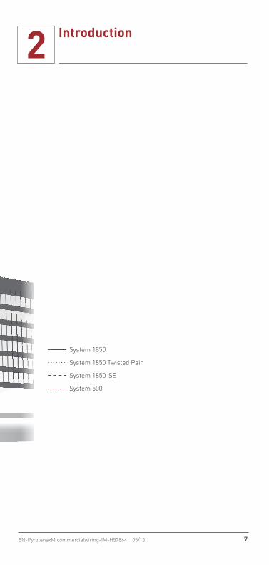
2.2 Typical MI Cable ApplicationsMI cable may be used in a wide variety of environ-ments. Typical applications of each cable system within a high-rise building are shown in Figure 2.
System 1850 2-hour Fire-Rated CableThe National Electrical Code and Canadian National Building Code recognize critical electrical circuits which, in the event of a fire, must continue to per-form their intended functions. NEC Article 695 and Article 700 address “Fire Pump” and “Emergency System” applications respectively. Both require a minimum of a 2-hour fire resistance rating which can be achieved by installing Pyrotenax System 1850 MI Cable. System 1850 can be found in the following environments:• Fire pump feeders• Emergency generator feeders• Emergency exhaust fans• Emergency lighting• Exit signs• Firefighter’s elevators• Emergency communications systems
System 1850-SE Service Entrance CableSystem 1850-SE is an MI service entrance wiring cable system that allows service entrance conduc-tors to be routed inside the building. In some juris-dictions, the Authorities Having Jurisdiction (AHJs) have accepted this system as an alternative where conditions make concrete encasement difficult or impractical. System 1850-SE can be used in the fol-lowing environments:• High-rise buildings• Health care facilities• Historic buildings• Airports, stadiums, hotels, banks, etc.

6 EN-PyrotenaxMIcommercialwiring-IM-H57864 05/13
2 Introduction
System 500 Non-Fire-Rated CablePyrotenax System 500 MI power cable allows up to 80% space savings over traditional rigid conduit and wire solutions. The cable is easily installed in areas where space is limited and along difficult runs. System 500 can be found in the following environments:• High-rise buildings• Banks and financial institutions• Historic buildings where it can be installed
unobtrusively
Important: System 500 is not a fire-rated wiring cable.
System 1850
System 1850 Twisted Pair
System 1850-SE
System 500
Figure 2: Typical MI cable application
7EN-PyrotenaxMIcommercialwiring-IM-H57864 05/13
2 Introduction
System 500 Non-Fire-Rated CablePyrotenax System 500 MI power cable allows up to 80% space savings over traditional rigid conduit and wire solutions. The cable is easily installed in areas where space is limited and along difficult runs. System 500 can be found in the following environments:• High-rise buildings• Banks and financial institutions• Historic buildings where it can be installed
unobtrusively
Important: System 500 is not a fire-rated wiring cable.
System 1850
System 1850 Twisted Pair
System 1850-SE
System 500
Figure 2: Typical MI cable application

8 EN-PyrotenaxMIcommercialwiring-IM-H57864 05/13
3 Storage and Handling
MI cable is very rugged; however, following the stor-age and handling measures below will minimize the possibility of damage to the cable.
3.1 StorageTo protect cables from physical damage and the environment, store indoors and protect from mois-ture, construction equipment, falling objects, chemi-cal spills, moving vehicles, and other hazards.
Initial InspectionWhen the cables are received:• Inspect the protective covering on the cable for
evidence of shipment damage.• Leave the factory-applied protective cover in place
until removal is absolutely necessary.• Where possible, check the copper sheath and, if
supplied, the polymer jacket, for evidence of ship-ment damage.
Pyrotenax MI cables are shipped from the factory with the exposed ends sealed with heat shrinkable end caps. These caps are weatherproof and seal the cable against moisture and other contaminants during shipment and storage. If the ends are dam-aged, missing, or removed, check the insulation resistance for the presence of moisture in the cable using a megohmmeter (see Section 6). If moisture is present, follow the instructions in Appendix C to remove the moisture or contact Pentair Thermal Management for guidance.
Important: Do not remove heat shrinkable end caps until ready to terminate the cable.
Storage Measures• Store cables indoors in a dry location.• Do not stack reels.• Ensure that both ends of the cable are securely
fastened to the reel flange.• Do not remove the protective heat shrinkable end
caps until the cable is ready to be terminated.

9EN-PyrotenaxMIcommercialwiring-IM-H57864 05/13
3 Storage and Handling
• Do not store reels flat. Store reels upright on their flanges (Figure 3).
• Store reels on a firm surface, paved if possible, or on planking to prevent reels from rotting.
• Cover reels with additional protection to shield against the effects of the environment, such as when stored in excessively damp, dirty, or dusty areas.
Always load and store reels upright on their flanges and block securely.
Upended heavy reels will often be damaged.
Right WrongFigure 3: Store reels upright on flanges
3.2 Handling
Moving Reels• Handle or install cables within suitable tempera-
ture limits (See Section 4.1).• Handle in a manner that prevents deterioration
of, and physical damage to, the reel and to the cable.
• Handle cable reels utilizing equipment designed for that purpose.
• Do not drop reels from any height, particularly from trucks or other transporting equipment.
• Lift or handle cable reels in such a manner that the lifting/handling device does not make direct contact with the cable or its protective covering.

10 EN-PyrotenaxMIcommercialwiring-IM-H57864 05/13
3 Storage and Handling
• Take precautions to ensure that the flange of one reel does not impact the cable on another reel.
Important: If a reel is dropped or damaged or the protective covering is damaged, examine the MI cable.
The following lifting methods are recommended (Figure 4):• Insert a suitable properly-secured shaft through
the reel arbor hole and lift with slings using a crane or boom-type equipment. Use a spreader or other device to minimize sling pressure against the reel flange.
• Move smaller, narrower reels using a forklift. Place fork tines so that lifting pressure is on both reel flanges, not on the cable.

11EN-PyrotenaxMIcommercialwiring-IM-H57864 05/13
3 Storage and Handling
Lower reels from a truck using a hydraulic gate, hoist or fork lift. LOWER CAREFULLY.
Right Wrong
Reels can be hoisted with a properly secured shaft extending through both flanges.
Cradle both reel flanges between fork tines.
Never drop reels.
Do not lift by a single reel flange. Cable or reel may be damaged.
Never allow fork tines to touch the cable surface or reel wrap.
Figure 4: Reel handling DOs and DON’Ts

12 EN-PyrotenaxMIcommercialwiring-IM-H57864 05/13
3 Storage and Handling
• Roll reels to move them short distances and in the direction so that the cable does not unwind (Figure 5); this will tighten the cable windings, not loosen them. Surfaces over which the reels are rolled must be firm, level, and clear of debris that may damage the cable.
Roll reel in the direction indicated by the arrow.
Figure 5: Reel rolling
Uncoiling Cable• Do not transfer cable to another reel as it will
become work hardened making it less easy to install.
• Uncoil cable with reel or coil in the vertical posi-tion by rolling rather than pulling from the periph-ery or the center of the coil or feed cable from a pay-off-reel (Figure 6). This will greatly ease the handling and prevent possible twisting, bending, and kinking.
• Use appropriate precautions when uncoiling cable (see Section 4.2).
• Handle cable carefully during uncoiling to prevent damage due to kinking or bending to radius small-er than allowable limits.
• Ensure that the cable is not twisted during installation.
• Do not lay cable on rough ground, run over cable, drag cable over sharp objects, or subject cable to other such treatment that could cause damage.
• Do not bend cable to a radius smaller than the minimum pulling radius when uncoiling (see Table 2 on page 24).

13EN-PyrotenaxMIcommercialwiring-IM-H57864 05/13
3 Storage and Handling
Right Wrong
Right Wrong
Reel
Coil
Figure 6: Unreeling/uncoiling cable

14 EN-PyrotenaxMIcommercialwiring-IM-H57864 05/13
4 Pre-Installation
This section deals with factors that should be considered prior to installation. It is highly recom-mended that cable installations be preplanned. It is important to ensure that personnel are properly trained and qualified for the specific task they are performing. All applicable rules and regulations including federal, state, local, and municipal laws must be followed. For further information on install-ing MI cables, contact Pentair Thermal Management Technical Support at (800) 545-6258.
4.1 Minimum Installation TemperatureDue to the fact that cable materials become brittle at low temperatures, a minimum installation tem-perature of 14°F (–10°C) is recommended for MI cables because this will allow for a considerable degree of rough handling. However, bare MI cable may be installed at a temperature as low as –40°F (–40°C).
When installing System 500 polymer jacketed cables, warm in a heated area (at least 50°F (10°C)) for at least 24 hours prior to installation. Install cable as quickly as possible after warming.
Important: System 1850 cables used in fire-rated applications are not available with a polymer jacket.
4.2 PrecautionsWhen installing Pyrotenax MI cables, all appropriate precautions shall be followed, including OSHA and other applicable regulations. Therefore, in addition to observing standard safety practices, observe the following:• Ensure that the cable reel is properly secured
prior to cable installation.• Use pulling devices and the pull rope within their
rating.• Make sure all equipment is in good operating
condition.• Take appropriate measures to protect personnel
in case the pull rope breaks. Personnel shall not stand in line with a pull rope that is under tension.

15EN-PyrotenaxMIcommercialwiring-IM-H57864 05/13
4 Pre-Installation
• Take reasonable precautions to prevent damage to the cable from severe blows with sharp instru-ments and pulling over sharp objects.
• Do not pull cables around corners that have sharp edges, such as corners in cable trays, or other obstructions. Use cable sheaves of the proper diameter (see Table 2 on page 24) or hand feed cables if possible.
• Protect exposed cables from any nearby or over-head work that could damage the cable.
• Do not pull cables around a radius smaller than the minimum pulling radius (see see Table 2 on page 24).
It is recommended that cable sizes from 1/0 AWG to 500 kcmil be pulled one at a time. When pulling smaller cable sizes, limit pulls of more than one cable run to straight sections only. Cables can then be individually pulled past bends using properly sized sheaves or rollers.
4.3 Installation Equipment
Pulling EquipmentSmall diameter MI cables may be installed by hand; however, it is recommended that large diameter MI cables be installed using mechanical pulling equip-ment that provides a steady continuous pull on the cable. Use pulling equipment with a capacity large enough to handle the maximum allowable pulling tension (see Table 3 on page 26) on each cable run without causing damage to the equipment or cables. Consult the pulling equipment manufac-turer’s specifications for capacity limitation.
To prevent damage to the cable during installation, use pulling equipment that can monitor pulling tensions and limit the cable tension to less than the maximum allowable pulling tension. Monitor the pull force for all high tension pulls (such as mechanical pullers, tuggers, and so on) using a ten-sion measuring device.

16 EN-PyrotenaxMIcommercialwiring-IM-H57864 05/13
4 Pre-Installation
SheavesUse sheaves or pulleys of the proper diameter to avoid damage to the cable (see see Table 2 on page 24).
Pulling RopeUse non-stretch pulling rope with swivels between the cable and pulling rope (pull rope diameter and length will depend on the pull to be made and pull-ing equipment available). Use a pulling rope with a capacity large enough to handle the maximum allowable pulling tension (see Table 3 on page 26) on each cable run without causing damage to the equipment or cables. Consult the pulling equipment and pulling rope manufacturer’s specifications for capacity limitation.
SwivelsTo prevent damage to the cable from possible twist-ing forces imparted when pulling the cable, use swivels between the cable grips and pull rope on all mechanically assisted pulls. The capacity of the swivel shall be large enough to handle the maximum allowable pulling tension on each cable run without causing damage to the equipment or cables. Consult the swivel manufacturer’s specifications for capacity limitation.
4.4 Set-upBefore installation, verify that the cable(s) can be installed according to the designed routing and minimum bending radius requirements. Take pre-cautions when routing in close proximity to hot pipes or other heat sources because of ampacity consid-erations. For 350 and 500 kcmil cables with pulls over 360 degrees in total offsets and bends, contact Pentair Thermal Management Technical Support at (800) 545-6258.
Examine trapeze support systems, cable trays, and other support systems for acceptability prior to pull-ing activities. Install permanent supports properly to ensure the rigidity of the trapeze, cable tray, or other support system so that neither the support system nor the cable will be subjected to damage during the pulling process.

17EN-PyrotenaxMIcommercialwiring-IM-H57864 05/13
4 Pre-Installation
Minimize the amount of tension necessary to pull a cable as follows:• Set up the cable reel assembly properly. The first
sheave must be installed at a point higher than the support system (Figure 7). The setup shall ensure that the cable is not kinked or bent beyond the minimum pulling radius or subject to exces-sive twisting force.
• Pull in the proper direction. Where practical, a cable pull should begin nearest the end having the least degrees of bends and exit the end having the greater degrees of bends if at all possible. Also, in vertical sections, an upward pull is preferred.
• Minimize the number and degrees of bends the cable is pulled around under tension. Accomplish this by finding the straightest route possible using the least amount of bends.
Sheave Roller
Right Wrong
Figure 7: Reel setup
Station an experienced cable pulling observer at the pulling end, in contact (visually, by radio, or by phone) with the other members of the crew. Use a suitable guide device to protect and guide the cable from the cable reel into the trapeze or tray. Make sure that the radius of the feeder device is not less than the minimum pulling radius of the cable. Protect cables exiting the trapeze or tray by similar means.

18 EN-PyrotenaxMIcommercialwiring-IM-H57864 05/13
4 Pre-Installation
4.5 Cable Attachment MethodsInstall cable grips and pulling eyes according to the manufacturer’s instructions. Form all cable connec-tions to the pulling device in a cylindrical configura-tion. Do not exceed the maximum allowable pulling tension (see Table 3 on page 26).
Basket Weave Grips or Split GripsUse basket weave or split grips to pull cables. Attach the grip to the cable sheath rather than the conduc-tor. Ensure grip is securely fastened to the cable sheath to prevent it from loosening during the pull. Use a swivel between the grip and pulling rope. For other cable attachment methods, contact Pentair Thermal Management Technical Support.
Pulling EyeAttach the pulling eye to the conductors. Use a swiv-el between the pulling eye and pulling rope.

19EN-PyrotenaxMIcommercialwiring-IM-H57864 05/13
5 Installation
The information in Section 5.1 applies to all MI cable installations unless otherwise noted. Further instal-lation details that apply specifically to System 1850 2-hour fire-rated cables, System 1850-SE service entrance cables, and System 500 non-fire-rated cables are shown in Sections 5.2 through 5.4. Following these installation instructions will con-sistently produce satisfactory MI cable installa-tions. Further information on proper installation techniques may be obtained by contacting Pentair Thermal Management Technical Support at (800) 545-6258.
5.1 General Installation GuidelinesThis section covers general installation guidelines that apply to Pyrotenax MI cables.• Where independent circuits are required or
desired, maintain proper separation and segrega-tion from other electrical circuits.
• All conductors of the same circuit, and where used, the grounded conductor (neutral) and all conductors bonding equipment to ground, must be contained within the same cable tray or bundled with the cables within a trapeze system or equiva-lent, unless otherwise permitted in accordance with the NEC/CEC. These requirements apply separately to parallel circuits.
• Protect cables from physical damage. The cable is generally not installed in conduit. Refer to MI cable in the NEC and CEC.
• Metal components and cable sheath must be of materials suitable for the environment in which they are to be installed.
• For concrete encasement, the copper sheath must be covered with a polymer jacket. Polymer jacket cables must not be used in applications where a fire-rating is required.
• Metal supports, cable sheath, and other metal enclosures for the cables must be metallically joined together and must be connected to all boxes, fittings, and cabinets so as to provide effec-tive electrical continuity.

20 EN-PyrotenaxMIcommercialwiring-IM-H57864 05/13
5 Installation
• Cable shall be pulled in line with the reel. Maintain a slow but steady speed to eliminate galloping (surging) and avoid reverse bending or overrunning. This can be achieved by applying a light back pressure on the cable reel as the cable leaves the reel.
• Conductors to be joined in parallel shall follow the applicable sections of the NEC/CEC.
• Where a single conductor carrying alternating current passes through metal with magnetic properties, the inductive effect shall be mini-mized by:(a) cutting slots in the metal between the indi-vidual holes through which the individual conduc-tors pass.(b) passing all the conductors in the circuit through a brass plate sufficiently large for all of the conductors of the circuit (Figure 14).
• Multiple circuits shall be appropriately spaced for ampacity considerations.
• Ensure that you do not invalidate the listing of the equipment when cutting holes.
• Install cables in accordance with the applicable requirements of the NEC or CEC and all other state/provincial or local codes.
Moisture AbsorptionThe magnesium oxide insulation of MI cable absorbs moisture when left exposed to air, causing the insulation resistance (IR) to fall. Low IR can be corrected as outlined in Appendix C.
Expansion and VibrationWhen crossing expansion joints, or when connect-ing the cable to vibrating equipment, it may be nec-essary to take precautions to prevent mechanical damage to MI cable. See Appendix B for details.
Protection Against CorrosionBare copper sheathed MI cable can be used without additional protection for most commercial installa-tions. In areas of high humidity, or where moisture is present and the bare copper cable is in contact

21EN-PyrotenaxMIcommercialwiring-IM-H57864 05/13
5 Installation
with dissimilar metals, it is recommended that the cables be supported as follows:• For fire-rated applications, wrap electrical tape
around the copper MI cable to prevent corrosion of the cable tray or strut at the point of contact and use only copper or stainless steel clamps to bundle the cables.
• For non-fire-rated applications, wrap electrical tape around the copper MI cable to prevent corro-sion of the cable tray or strut at the point of con-tact and use copper or stainless steel clamps, or use clamps with an integral rubber liner, to bundle the cables.
In corrosive environments, the copper sheath must be covered with a polymer jacket. Polymer jacket cables must not be used in applications where a fire-rating is required.For more information on corrosion and MI cable, refer to publication number H57614 available from our web site at www.thermal.pentair.com.
Equipment BondingThe copper sheath of MI cable exceeds the code requirements for an equipment-to-ground bonding conductor. However, in the case of fire pump instal-lations using a 600% over-current protective device, a separate equipment-to-ground bonding conductor is required. Where it is foreseen that the ground con-tinuity may be subsequently impaired by corrosion of the enclosure, it is recommended that the enclosure be suitably protected.
Straightening and Dressing the CableThe cable is annealed before leaving the factory, making it soft and easy to handle. Prior to secur-ing the cable to a wall or ceiling, the cable may be straightened by hand or using a bending hickey (Figure 9). Final dressing may be carried out using a hammer and a block of wood, rubber mallet, etc., as shown in Figure 8. Do not use a metal hammer alone as it may result in unsightly dents that cannot be removed.

22 EN-PyrotenaxMIcommercialwiring-IM-H57864 05/13
5 Installation
Cables
CablesupportWooden
blockRubbermallet
Figure 8: Straightening and dressing MI cable
Bending RadiusAll normal bending may be carried out without the use of tools; however, two sizes of bending hickeys are available for use with the larger diameter cables or when multiple bends are required. These hickeys are specially designed to prevent cable damage dur-ing bending (Figure 9). Alternatively, a conduit bend-ing tool may be utilized.
When offsetting the cable to enter an enclosure via a gland, 2 to 3 in (50 to 75 mm) of straight cable should be left between the gland and the final bend to facilitate withdrawal of the gland from the enclosure.

23EN-PyrotenaxMIcommercialwiring-IM-H57864 05/13
5 Installation
Figure 9: Bending MI cable
The minimum bending radius for permanent training of Pyrotenax MI cable is shown in Table 1. The rela-tionship between cable diameter and bending radius is shown in Figure 10. Bend in small increments. Do not try to make the entire bend in one operation. Shape into final position gradually.
TABLE 1: MINIMUM BENDING RADIUS
Cable O.D. (Outside diameter) NEC CEC
0.75 in (19 mm) and smaller 5 times cable diameter
6 times cable diameter
Larger than 0.75 in (19 mm) 10 times cable diameter
12 times cable diameter
(see Table 1)
Note: CEC bending radius shown for 0.75" and smaller cables
Cable O.D.
Figure 10: Minimum bending radius

24 EN-PyrotenaxMIcommercialwiring-IM-H57864 05/13
5 Installation
Pulling the Cable into PositionPull the cable into position using a series of sheaves or pulleys (Figure 11). This ensures quick and neat installation, especially if a number of cables are being installed along a parallel path. Use the recom-mended sizes for sheaves or pulleys and observe the minimum pulling radius shown in Table 2 when pulling (using undersized sheaves or pulleys will result in work-hardening of the cable). For 350 and 500 kcmil cables with pulls over 360 degrees in total offsets and bends, contact Pentair Thermal Management Technical Support for assistance. Do not exceed the maximum allowable pulling tension shown in Table 3.
MI cable
Sheave or pulley(properly sized)
Figure 11: Pulling MI cable
TABLE 2: MINIMUM SHEAVE/PULLEY DIAMETER AND PULLING RADIUS
Cable diameter Sheave/pulley diameter Pulling radius
Smaller than0.5 in (12.7 mm)
10 in (250 mm) or larger 5 in (125 mm)
0.5 to 0.75 in (12.7 to 19 mm)
18 in (460 mm) or larger 9 in (230 mm)
Larger than0.75 in (19 mm)
24 in (610 mm) or larger 12 in (305 mm)
25EN-PyrotenaxMIcommercialwiring-IM-H57864 05/13
5 Installation
Maximum Allowable Pulling TensionWhen cables are pulled into cable tray or open runs, they are subjected to physical stresses caused by friction of the cable against the supporting and con-tact surfaces. Cable weight, direction of the pull, and the angle of the pull are all factors that have an effect on pulling tension. The maximum allowable pulling tension for Pyrotenax fire-rated and non-fire-rated MI cables is shown in Table 3.

26 EN-PyrotenaxMIcommercialwiring-IM-H57864 05/13
5 Installation
TABLE 3: MAXIMUM ALLOWABLE PULLING TENSION
System 1850 and System 1850-SE
System 500 non-fire-rated cable
Cable reference
Cable size (AWG/kcmil)
Tension (lbs)
Cable reference
Cable size (AWG/kcmil)
Tension (lbs)
1/500-1000 500 4200 1/500-975L 500 3400
1/350-834 350 3000 1/350-815L 350 2400
1/250-746 250 2300 1/250-699L 250 1800
1/4/0-684 4/0 2000 1/4/0-653L 4/0 1400
1/3/0-621 3/0 1600 1/10-230L 10 160
1/2/0-580 2/0 1300
1/1/0-512 1/0 1100
1/1-496 1 900
1/2-449 2 750
1/3-449 3 640
1/4-402 4 520
1/6-340 6 370
1/8-298 8 260
1/10-277 10 200
1/12-246 12 170
1/14-230 14 140
1/16-215 16 100
2/1-975 1 2300 2/10-418L 10 400
2/2-865 2 1800 2/12-355L 12 300
2/3-768 3 1450 2/14-324L 14 230
2/4-684 4 1100
2/6-590 6 800
2/8-512 8 600
2/10-449 10 500
2/12-402 12 350
2/14-371 14 300
2/16-340 16 220

27EN-PyrotenaxMIcommercialwiring-IM-H57864 05/13
5 Installation
TABLE 3: MAXIMUM ALLOWABLE PULLING TENSION
System 1850 and System 1850-SE
System 500 non-fire-rated cable
Cable reference
Cable size (AWG/kcmil)
Tension (lbs)
Cable reference
Cable size (AWG/kcmil)
Tension (lbs)
3/3-834 3 1900 3/8-480L 8 650
3/4-746 4 1500 3/12-387L 12 360
3/6-621 6 1000
3/8-590 8 700
3/10-480 10 500
3/12-480 12 400
3/14-387 14 310
3/16-355 16 240
4/6-730 6 1300 4/10-480L 10 570
4/8-590 8 900 4/14-371L 14 300
4/10-590 10 600
4/12-465 12 500
4/14-465 14 420
4/16-387 16 290
7/8-710 8 1200 7/10-559L 10 900
7/10-621 10 1000 7/12-480L 12 600
7/12-543 12 700 7/14-434L 14 460
7/14-496 14 500
7/16-449 16 400
Important: Because MI cable is delivered in a soft annealed state, the maximum pulling tension must not be exceeded. Exceeding the maximum pulling tension may stretch the cable, resulting in loss of insulation and sheath thickness, and reduced conductor diameter.
28 EN-PyrotenaxMIcommercialwiring-IM-H57864 05/13
5 Installation
Brass PlatesWhen single-conductor cables enter a ferrous metal enclosure, precautions must be taken to prevent heating by induction. This is done by cutting out a section of the steel enclosure and replacing it with a 1/4 in (6.4 mm) thick brass plate (Figure 12 and Figure 14) at each end of the cable run. Avoid cutting holes in listed enclosures, such as wet-rated and fire pump enclosures, as it might void the enclosure’s listing; check with the enclosure’s manufacturer if in doubt. When cutting a hole in the enclosure is not allowed, the cables must be terminated into an intermediate enclosure (through a brass plate) and introduced into the listed enclosure through a con-ventional raceway entry (Figure 13).
Bond the brass plate to the enclosure using a prop-erly sized bonding conductor. This is achieved by drilling and tapping an appropriate sized hole at a suitable location on the brass plate, and bolting a connector, sized for the bonding conductor, to the plate. The brass plate is not required when installing multiconductor cables.
In the USA, the NEC requires the brass (nonferrous) plate for all single-conductor cables. In Canada, the CEC requires the brass plate only when conductor current exceeds 200 A.
Important: Ensure that enough material remains around the edges of the enclosure to allow the brass plate to be attached to the enclosure as shown in Figure 12.

29EN-PyrotenaxMIcommercialwiring-IM-H57864 05/13
5 Installation
Brassplate
Cut and remove metalbelow brass plateleaving just enoughmaterial around edgeto mount plate
Note: Not suitable for fire pump controllers
Steelenclosure
Figure 12: Brass plate installation
Brass plate
Steel enclosure
Fire pumpcontroller
Conduit to firepump controller
Entry in accordance withfire pump controllermanufacturer’s instructions
MI cable
Figure 13: Recommended method of connecting MI cable to fire pump controller
For free air installations as described in the NEC/CEC, the transition from bundled cables must com-mence 24 in (610 mm) minimum from the enclosure as shown in Figure 14.

30 EN-PyrotenaxMIcommercialwiring-IM-H57864 05/13
5 Installation
MulticonductorMI cable
enters ferrousenclosure
withoutbrass plate
Single-conductorMI cables
Brass gland
Brass plate1/4" (6 mm)thick (sizeas required)
Steelenclosure
Lockwasher
Details of brass plate
Steel enclosurecutout (steel must be removed frombeneath brassplate)
1/2", 3/4", 1", 1-1/4" NPT drilledand tapped holesas required
Lockwasher
Lock nuts
For “free air” ratings, the transition from bundled cables must commence 24" (610 mm) minimum from the enclosure
The brass plate must be bonded to the enclosure. Drill and tap the brass plate to accept the bonding connector. For separately derived systems, refer to the NEC
Figure 14: Equipment grounding/bonding using brass plate
Emergency GeneratorWhen connecting MI cable to an emergency gen-erator, terminate the MI cables in an intermediate enclosure through a brass plate. Use flexible cables to make the connection from the intermediate enclo-sure to the generator.

31EN-PyrotenaxMIcommercialwiring-IM-H57864 05/13
5 Installation
5.2 Installing Pyrotenax System 1850 2-Hour Fire-Rated CableThe instructions in Section 5.2 are for Pyrotenax System 1850 2-hour fire-rated MI cable, a 2-hour fire-rated system as classified by UL and listed by ULC. The details of this system appear in the Fire Resistance Directory under Electrical Circuit Integrity Systems (FHIT/FHITC), System No. 1850, and are reproduced in Appendix A. These require-ments must be followed to maintain the 2-hour rating in a fire-rated area.
A typical 2-hour fire-rated power circuit installation utilizing System 1850 MI cable is shown in Figure 15. In addition to the requirements in Electrical Circuit Integrity Systems (FHIT/FHITC), System No. 1850, these systems must be installed in accordance with all provisions of the NEC/CEC and the requirements in this manual.
Important: Authorities Having Jurisdiction should be consulted in all cases as to the specific require-ments covering the installation and use of these clas-sified systems.

32 EN-PyrotenaxMIcommercialwiring-IM-H57864 05/13
5 Installation
Emergencysplitter
Emergencysplitter
Generator
Firepump
Transferswitch
Transferswitch
Mainelectricalswitchgear
Factoryjoint
Brass plate
QuickTerm terminationkit
Flexibletails
Gearclamp
Pipeclamp
System 1850 fire-rated MI cable
Figure 15: Typical System 1850 2-hour fire-rated power circuit
Single-Conductor CableArrange the cable runs in the configurations shown in Figure 16, Figure 17, and Figure 18. Cables may be run in trifoil or quadrifoil (includes a neutral), or alternatively, side-by-side configuration. The trifoil/quadrifoil configuration is recommended for best sheath current cancellation.
Bundle the cables in groups containing one conduc-tor from each phase with the sheaths touching over the entire length of the run, except when entering the enclosure (see Figure 14). Where parallel runs are required, cable bundles must be spaced distance “S” apart as shown in Figure 16, Figure 17, and Figure 18. If using a separate equipment-to-ground

33EN-PyrotenaxMIcommercialwiring-IM-H57864 05/13
5 Installation
bonding conductor, bundle it within the cable group, and when entering the enclosure, connect it to the brass plate using an appropriate connector and then bond the plate to the enclosure. Follow the require-ments of the NEC/CEC as applicable, when installing parallel runs of cable.
Single circuit(preferred)
Single circuit(alternative)
Two cables inparallel per phase
(preferred)Two cables in
parallel per phase(alternative)
Three or more cablesin parallel per phase
(preferred)Three or more cablesin parallel per phase
(alternative)
Note: For free air ampere ratings, the spacing “S” between bundles shall be a minimum of 2.15 cable diameters in the U.S. (NEC), and Canada (CEC). For magnetic effect purposes, the neutral may be located as shown, or outside groups in the most convenient location.
S
S
S S
Single Phase
SS
Figure 16: Recommended installation configurations, single phase

34 EN-PyrotenaxMIcommercialwiring-IM-H57864 05/13
5 Installation
Single circuit(preferred)
Single circuit(alternative)
Two cables inparallel per phase
(preferred)Two cables in
parallel per phase(alternative)
Three or more cablesin parallel per phase
(preferred)Three or more cablesin parallel per phase
(alternative)
S
S
S
S
S
S
Three-Phase • 3 Wire
Note: For free air ampere ratings, the spacing “S” between bundles shall be a minimum of 2.15 cable diameters in the U.S. (NEC), and Canada (CEC). For magnetic effect purposes, the neutral may be located as shown, or outside groups in the most convenient location.
Figure 17: Recommended installation configurations, three-phase • 3 wire
Single circuit(preferred)
Single circuit(alternative)
Two cables inparallel per phase
(preferred)Two cables in
parallel per phase(alternative)
Three or more cablesin parallel per phase
(preferred)Three or more cablesin parallel per phase
(alternative)
Note: For free air ampere ratings, the spacing “S” between bundles shallbe a minimum of 2.15 cable diameters in the U.S. (NEC), and Canada (CEC). For magnetic effect purposes, the neutral may be located as shown, or outside groups in the most convenient location.
S
S
S
S
S
S
Three-Phase • 4 Wire
Figure 18: Recommended installation configurations, three-phase • 4 wire

35EN-PyrotenaxMIcommercialwiring-IM-H57864 05/13
5 Installation
On horizontal and vertical runs, MI cable may be supported with steel channel as shown in Figure 19.
Concrete ormasonry surface
Pipe/conduit clampwith fasteners
Support to fire-rated structureusing approved fasteners
Single-conductorMI cables
Spacing “S” betweenmultiphase paralleled
single-conductor cables
Figure 19: Supporting MI cables using steel channel
Multiconductor CableA brass plate is not required for multiconductor cables. Connect the brass termination gland directly to the steel enclosure using lock nuts on either side of the gland connector as shown in Figure 14. Ensure that the brass gland is properly bonded to the steel enclosure once the lock nuts have been tightened. Install multiconductor cables following all applicable requirements in the NEC/CEC.
Twisted Pair Fire Alarm and Communication CableSystem 1850 twisted pair cables are installed in the same manner as multiconductor cables. When installing circuits requiring twisted pair cables, ensure that the cable parameters are compatible with the equipment.

36 EN-PyrotenaxMIcommercialwiring-IM-H57864 05/13
5 Installation
Exposed or Surface InstallationsComponents used to support System 1850 MI fire-rated cable must be made of appropriate materials such as copper, steel, or stainless steel and attached to a fire-rated surface (such as concrete or masonry) equal to the cable rating.
Important: Do not use material such as aluminum, brass, plastic, lead, wood, etc., since these materials will fail quickly during a fire and jeopardize the integ-rity of the electrical circuit protective system.
Important: If a fire-rated surface is not available, please contact the local Authority Having Jurisdiction for assistance.
Important: The actual sizes of hangers, bolts, nuts and fasteners are to be adjusted for the weight sup-ported and area seismic conditions. Provide seismic bracing where required. Comply with “System 1850” UL Fire Resistance Directory.
System 1850 MI fire-rated cable must be support on horizontal and vertical runs by a 2-hour fire-rated assembly, with supports spaced according to the requirements in Table 4.
TABLE 4: MAXIMUM SPACING BETWEEN SUPPORTS AND STRAPS/GEAR CLAMPS IN FIRE-RATED INSTALLATIONS
Cable diameter
Horizontal/ vertical supports
Straps/gear clamps
0.3 in (7.6 mm)and smaller
4 ft (1220 mm) 2 ft (610 mm)
Greater than0.3 in (7.6 mm)
6 ft (1830 mm) 3 ft (915 mm)
Install exposed runs of cables parallel to build-ing lines to present a neat appearance as shown in Figure 8. When subject to potentially damaging abuse, protect the cable with angle iron, steel chan-nel, or a short piece of conduit.

37EN-PyrotenaxMIcommercialwiring-IM-H57864 05/13
5 Installation
Figure 20: MI cable bends
When transitioning from a straight run of MI cable to a bend, use additional supports at the start of the bend and the end of the bend as shown in Figure 20. All cable runs, including bundled cables, must be supported in this manner using the support method being utilized (i.e. trapeze, steel channel, clips and straps, or the banding & bracket system).
Several support methods may be used, as shown fol-lowing; however, the steel rod and channel (trapeze) system is recommended due to its wide availability and familiarity among installing contractors.
Important: Follow all requirements in Section 5.1 when installing cables.
Trapeze SupportThe trapeze support system shown in Figure 21 and Figure 22 must consist of 12 gauge, 1-1/2 in (38 mm) or 1-5/8 in (41 mm) minimum, galvanized, slotted steel channel with hemmed flange edges; width of the steel channel must not exceed 36 in (915 mm). Rods must be 3/8 in (10 mm) diameter minimum threaded steel rods with 1-1/2 in (38 mm) steel washers and steel nuts. Securely anchor steel

38 EN-PyrotenaxMIcommercialwiring-IM-H57864 05/13
5 Installation
rods to a fire-rated structure, such as concrete or masonry.
Bundle single-conductor MI cables tightly together in groups (see Figure 16, Figure 17, and Figure 18 for configurations) and secure cables in place with 16 gauge minimum steel single bolt pipe clamps, sized to correspond with the outside diameter of the cable or cable bundle (Figure 21 and Figure 22). Table 5 shows recommended loading guidelines for a trapeze-type system that is used to support MI fire-rated cables.
Additionally, bundle each group of cables tightly together between supports using stainless steel gear clamps or using 1/2 in (13 mm) wide by 0.020 in (0.51 mm) thick stainless steel straps in conjunc-tion with 1/2 in (13 mm) wide steel banding clips as shown in Figure 21 and Figure 22. Refer to Table 4 for spacing.
Do not exceed the support spacing shown in Table 4. Anchors for the trapeze system/tray MUST BE STEEL. Aluminum or other low melting point materials and combustible materials are NOT ACCEPTABLE. For further information on the tra-peze installation method, contact Pentair Thermal Management Technical Support at (800) 545-6258.
39EN-PyrotenaxMIcommercialwiring-IM-H57864 05/13
5 Installation
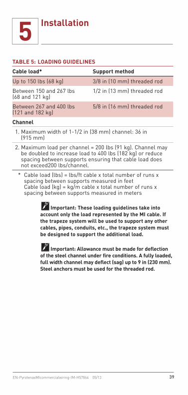
TABLE 5: LOADING GUIDELINES
Cable load* Support method
Up to 150 lbs (68 kg) 3/8 in (10 mm) threaded rod
Between 150 and 267 lbs (68 and 121 kg)
1/2 in (13 mm) threaded rod
Between 267 and 400 lbs (121 and 182 kg)
5/8 in (16 mm) threaded rod
Channel
1. Maximum width of 1-1/2 in (38 mm) channel: 36 in (915 mm)
2. Maximum load per channel = 200 lbs (91 kg). Channel may be doubled to increase load to 400 lbs (182 kg) or reduce spacing between supports ensuring that cable load does not exceed200 lbs/channel.
* Cable load (lbs) = lbs/ft cable x total number of runs x spacing between supports measured in feet Cable load (kg) = kg/m cable x total number of runs x spacing between supports measured in meters
Important: These loading guidelines take into account only the load represented by the MI cable. If the trapeze system will be used to support any other cables, pipes, conduits, etc., the trapeze system must be designed to support the additional load.
Important: Allowance must be made for deflection of the steel channel under fire conditions. A fully loaded, full width channel may deflect (sag) up to 9 in (230 mm). Steel anchors must be used for the threaded rod.

40 EN-PyrotenaxMIcommercialwiring-IM-H57864 05/13
5 Installation
Steel rod securelyanchored tofire-ratedstructureSupport spacing as
specified in Table 4
1-1/2 in (38 mm)minimum steelchannel
1-1/2 in (38 mm)steel washers and steel nuts
Spacing “S” betweenmultiphase paralleledsingle- conductorcables
MulticonductorMI cable
Pipe/conduitclamp withfasteners
Single-conductorMI cables
Stainless steel strap/gear clamp between supports as shown in Table 4
Figure 21: Typical installation using trapeze support – common method

41EN-PyrotenaxMIcommercialwiring-IM-H57864 05/13
5 Installation
Steel rod securelyanchored tofire-ratedstructure
Support spacing asspecified in Table 4
1-1/2 in (38 mm)minimum steelchannel 1-1/2 in (38 mm)
steel washers and steel nuts
Spacing “S” betweenmultiphase paralleledsingle-conductorcables
MulticonductorMI cable
Pipe/conduitclamp withfasteners
Single-conductorMI cables
Stainless steel strap/gear clamp between supports as shown in Table 4
Figure 22: Typical installation using trapeze support – alternate method

42 EN-PyrotenaxMIcommercialwiring-IM-H57864 05/13
5 Installation
Surface Mounted Using Steel ChannelThe installation methods shown in Figure 23 and Figure 24 may be used as alternatives to trapeze type support systems.
For surface mounted installations, use 12 gauge, 1-1/2 in (38 mm) or 1-5/8 in (41 mm) minimum, gal-vanized, slotted steel channel with hemmed flange edges. Securely anchor the steel channel to a fire-rated structure, such as concrete or masonry, using 1/4 in (6.4 mm) diameter minimum by 2-1/4 in (57 mm) long minimum steel concrete screws or other approved fasteners.
Bundle single-conductor MI cables tightly together in groups (see Figure 16, Figure 17, and Figure 18 for configurations) and secure cables in place with 16 gauge minimum steel single bolt pipe clamps, sized to correspond with the outside diameter of the cable or cable bundle (Figure 23 and Figure 24).
Additionally, bundle each group of cables tightly together between supports using stainless steel gear clamps or using 1/2 in (13 mm) wide by 0.020 in (0.51 mm) thick stainless steel straps in conjunc-tion with 1/2 in (13 mm) wide steel banding clips as shown in Figure 23 and Figure 24. Refer to Table 4 for spacing. This minimizes sheath currents and stabilizes the cables under short circuit and fire conditions.
Do not exceed the support spacing shown in Table 4. For further information on this installation method, contact Pentair Thermal Management Technical Support.

43EN-PyrotenaxMIcommercialwiring-IM-H57864 05/13
5 Installation
Support spacing asspecified in Table 4
Support tofire-rated structureusing approvedfasteners
Single-conductorMI cables
Pipe/conduit clampwith fasteners
Spacing “S” betweenmultiphase paralleledsingle-conductor cables
Concrete ormasonry
wall
1-1/2 in(38 mm)
steel channel (to
maintain NEC/CEC
free air rating)
Stainless steel strap/gear clamp between supports as shown in Table 4.
Figure 23: Typical horizontal surface-mounted installation using steel channel

44 EN-PyrotenaxMIcommercialwiring-IM-H57864 05/13
5 Installation
Support spacing as specified in Table 4
Support to fire-ratedstructure usingapproved fasteners
1-1/2 in (38 mm)steel channel(to maintainNEC/CEC free air rating)
Pipe/conduit clampwith fasteners
Spacing “S” betweenmultiphase paralleledsingle-conductor cables
Concrete or masonry wall
Single-conductorMI cables
Stainless steel strap/gear clamp between supports as shown in Table 4.
Figure 24: Typical vertical surface-mounted installation using steel channel

45EN-PyrotenaxMIcommercialwiring-IM-H57864 05/13
5 Installation
Surface Mounted Using Clips and StrapsSupport multi-conductor cables directly to concrete or masonry surfaces using 3/8 in to 1 in (9.5 to 25 mm) wide copper clips or straps (Figure 25) avail-able from Pentair Thermal Management.
Bundle the MI cables tightly together in side-by-side groups and securely anchor the clips or straps to the structure using 3/16 in (4.8 mm) diameter minimum by 2-1/4 in (57 mm) long minimum steel concrete screws or other approved fasteners.
Do not exceed the support spacing shown in Table 4. For further information on this installation method, contact Pentair Thermal Management Technical Support.
Copper clips or strapssecured to fire-rated
structure usingapproved fasteners
MulticonductorMI cable
Concrete ormasonry wall
Support spacing asspecified in Table 4
Figure 25: Typical surface-mounted installation using clips or straps

46 EN-PyrotenaxMIcommercialwiring-IM-H57864 05/13
5 Installation
Banding and Bracket Support SystemThe banding and bracket system shown in Figure 26 and Figure 27 is available from Pentair Thermal Management. This method may be used to support a single run of MI cable up to 500 kcmil, 3 bundled runs of cable up to 2/0 AWG, or 4 bundled runs of cable up to 1/0 AWG. The steel bracket is 1 in (25 mm) wide by 4-3/8 in (110 mm) long by 0.125 in (3.2 mm) minimum thickness and stainless steel strap-ping is 1/2 in (13 mm) wide by 0.020 in (0.51 mm) thick and is held together with 1/2 in (13 mm) wide steel banding clips.
Cut a 10 to 12 in (250 to 300 mm) piece of strapping from the roll, form one end as shown in Figure 26a, and push the other end through the banding clip. Insert the strapping through the two square holes in the hanger, then secure the bracket directly to a fire-rated structure, such as concrete or masonry, using 1/4 in (6.4 mm) diameter minimum by 2-1/4 in (57 mm) long minimum steel concrete screws or other approved fasteners (Figure 26b).
Insert temporary hangers into several brackets (Figure 26c) and fix the cables loosely along the lines they are being installed. Use the hangers to tempo-rarily support the cables. Bundle single-conductor MI cables tightly together in groups (see Figure 16, Figure 17, and Figure 18 for configurations). Band the cables to the bracket with the strapping. Use a tensioning tool to tighten the strapping and crimp the clip in place with a suitable crimping tool (Figure 26d).
Additionally, bundle each group of cables tightly together between supports using the stainless steel strapping and clips as shown in Figure 27. Refer to Table 4 for spacing. This minimizes sheath cur-rents and stabilizes the cables under short circuit and fire conditions. Figure 27 shows the completed installation.

47EN-PyrotenaxMIcommercialwiring-IM-H57864 05/13
5 Installation
ClipStainless steelstrapping
BracketClip
Strapping
Secure to fire-ratedstructure usingapproved fasteners
Cable
Hanger(used to temporarilysupport cables priorto banding)
DC
BA
Figure 26: Banding bracket installation

48 EN-PyrotenaxMIcommercialwiring-IM-H57864 05/13
5 Installation
Concrete ormasonry wall
Note: Use to support -
1 run of MI cable up to 500 kcmil3 bundled runs of cable up to 2/0 AWG4 bundled runs of cable up to 1/0 AWG
Single-conductorMI cables
Support spacingas specified inTable 4
Stainless steel strap/gear clamp between supports
as shown in Table 4.
Banding bracketand stainless steel
strapping supportedto fire-rated
structure usingapproved fasteners
Figure 27: Typical banding and bracket installation for supporting bundled MI cables
Cable TrayCable tray, when used to support cable in fire-rated applications, must be solid bottom, open ladder or ventilated trough type steel cable tray capable of functioning at temperatures to 1850°F for a period of two hours. The tray must be rigidly secured to the wall or floor assembly, supported at spacing requirements shown in Table 4, and installed per all national and local electrical codes. Typical “Loading Guidelines” may be found in Table 5.
Important: Trays made of aluminum, galvanized or zinc plated steel, or other low melting point materi-als are NOT ACCEPTABLE. Anchors for tray MUST BE STEEL.

49EN-PyrotenaxMIcommercialwiring-IM-H57864 05/13
5 Installation
Embedded InstallationsCables embedded in concrete must be protected against puncture damage from the medium itself, and the pouring equipment, by means acceptable to the engineer. Where a section of fire-rated cable may be embedded in concrete, the copper sheath must be protected from corrosion by wrapping electrical tape around the cable.When cables emerge from a slab, protect against shear damage by covering the cables with a short length of metal plate or angle iron, at the point of egress. This protection must extend 18 inches below finished grade to eight feet above finished grade.
Wall or Floor PenetrationsWhen System 1850 penetrates a wall or floor, place a sleeve in the opening to protect the cable during pulling operations. Once the cable is in place, fill the opening using an approved “fire-stop” system. A list of UL and ULC certified systems appears in the “Through-Penetration Fire Stop Systems” in the Fire Resistance Directory, Guide XHEZ and XHEZC respectively.
Factory-Installed JointWhen the circuit length exceeds the nominal coil length of a particular cable configuration, factory-installed welded joints (Figure 28) are supplied for cable diameters of 0.402 in (10.2 mm) and larger.Where factory-installed welded joints are supplied, reinforcing sleeves are affixed at both ends of every joint to avoid damage to the welds when the cable is pulled into position. Do not exceed the pulling ten-sion shown in Table 6.
Important: Factory-installed joints are only avail-able for cable diameters of 0.402 in (10.2 mm) and larger.

50 EN-PyrotenaxMIcommercialwiring-IM-H57864 05/13
5 Installation
Figure 28: Factory-installed joint for System 1850 MI cable
TABLE 6: MAXIMUM PULLING TENSION FOR FACTORY-INSTALLED JOINTS
Cable O.D. Pulling tension (lbs)
Smaller than 0.5 in (12.7 mm) See Table 3 for specific cable
0.5 to 0.74 in (12.7 to 18.8 mm)
See Table 3 for specific cable and limit pulling tension to the value in Table 3 or 1500 lbs maximum.
Larger than 0.74 in (18.8 mm) See Table 3 for specific cable and limit pulling tension to the value in Table 3 or 2200 lbs maximum.
The proper procedure for pulling cables with factory-installed joints is shown in Figure 29. Pull the joint past the sheave/pulley first, then bend the cable around the sheave/pulley by hand and continue pull-ing the cable.
Important: Do not pull the joint directly over a sheave/pulley.

51EN-PyrotenaxMIcommercialwiring-IM-H57864 05/13
5 Installation
Right Wrong
Figure 29: Procedure for pulling factory-installed joints
When fastening the joint to a wall or ceiling, sup-port the joint using the banding and bracket method shown in Figure 26. The joint must be supported at its center and 39 in (1 m) on either side of this sup-port as shown in Figure 30.
When using any other method to support fire-rated cables, such as a trapeze system, stagger the joints if possible and ensure that each joint is firmly sup-ported. This can be accomplished by supporting each joint with additional trapeze supports or by securing the joint on top of a section of steel channel and firmly attaching the channel between existing trapeze supports.
Steel bracket
Support spacingper Table 4 39 in 39 in
(1 m) (1 m)
Stainless steel banding
Joint
Figure 30: Supporting the factory-installed joint

52 EN-PyrotenaxMIcommercialwiring-IM-H57864 05/13
5 Installation
Cable TerminationsSystem 1850 must be terminated with one of three approved Pyrotenax terminations kits, the QuickTerm kit or the Sized-up QuickTerm kit for single-conduc-tor cables, or the Pyropak kit for single and multi-conductor cables (Figure 31). Follow the instructions supplied with these kits to complete the termination. Prior to installing the termination, check the cable with a 500 V megohmmeter, to ensure the IR is acceptable. Refer to Section 6 and the instructions supplied with the termination kit.
Important: The System 1850 MI cable terminations must be made outside the fire-zone.

53EN-PyrotenaxMIcommercialwiring-IM-H57864 05/13
5 Installation
Spacer diskand insulatingsleeving assembly
Self-sealingtape
Brassglands
Heat-shrinkablesleeving
Brassglands
Mastic sealingcompound
Crimpconnectors
Brasspots
Pyropak termination kit
QuickTerm termination kit
Figure 31: System 1850 termination kits

54 EN-PyrotenaxMIcommercialwiring-IM-H57864 05/13
5 Installation
5.3 Installing Pyrotenax System 500 Non-Fire-Rated CableThe instructions in Section 5.3 are for Pyrotenax System 500 non-fire-rated MI power cables. These cables are not fire-rated and must not be used where a fire-rating is required. Install System 500 cables in accordance with all provisions of the NEC/CEC and requirements in this manual. A typical power circuit installation utilizing System 500 MI cable is shown in Figure 32.
Main electricalswitchgear Equipment
enclosure
Brassplate
Gearclamp
Pipeclamp
Field splices
Brassplate
Flexibletails
Flexibletails
QuickTermtermination
kit QuickTermtermination
kit
Figure 32: Typical System 500 power circuit

55EN-PyrotenaxMIcommercialwiring-IM-H57864 05/13
5 Installation
System 500 cables may be installed by following the installation details for fire-rated cables shown in Section 5.2, with the following differences:• Cables may be installed on any surface capable of
supporting the cables.• Required spacing between cable supports is
shown in Table 7.
In addition to exposed and surface installations, System 500 cables may be embedded into plaster walls and easily hidden due to their small diameter.
Important: Follow all requirements in Section 5.1 when installing cables.
Important: The actual sizes of hangers, bolts, nuts, and fasteners are to be adjusted for the weight supported and area seismic conditions. Provide seis-mic bracing where required.
System 500 cables must be supported on horizontal and vertical runs according to the spacing require-ments in Table 7.
TABLE 7: MAXIMUM SPACING BETWEEN SUPPORTS FOR NON-FIRE-RATED INSTALLATIONS
Horizontal runs Vertical runs
USA 6 ft (1830 mm) 6 ft (1830 mm)
Canada 6.56 ft (2000 mm) 6.56 ft (2000 mm)
Factory-Installed and Field-Installed JointsWhen the circuit length exceeds the nominal coil length of a particular cable configuration, factory installed joints are supplied. For installation details, refer to Section 5.2. A field installed joint is also available to extend the cable length (Figure 33).

56 EN-PyrotenaxMIcommercialwiring-IM-H57864 05/13
5 Installation
Factory-installed joint
Field-installed joint
Figure 33: Joints for System 500 MI cable
Cable TerminationsThe cable termination for System 500 cable is identical to the termination for System 1850 cable. Refer to Section 5.2 for more information on cable terminations.
5.4 Installing Pyrotenax System 1850-SE Service Entrance Cable SystemThe instructions in Section 5.4 are for the Pyrotenax System 1850-SE Service Entrance Cable System. The system is designed as an alternative to concrete encasement for service conductors and provides a 2-hour fire-rating. A typical service entrance system utilizing System 1850 single-conductor MI cable is shown in Figure 34.
Important: Authorities Having Jurisdiction (AHJs) must be consulted in all cases as to the specific requirements covering the installation and use of the Pyrotenax service entrance cable system. In some jurisdictions, the AHJs have accepted this system as an alternative where conditions make concrete encase-ment difficult or impractical.

57EN-PyrotenaxMIcommercialwiring-IM-H57864 05/13
5 Installation
In areas with high levels of thunderstorm activ-ity, the System 1850 cables must be protected with the lightning protection package (Part number: SE-PROTECT). This kit may also be used in any loca-tion where there is a concern about lightning activ-ity. Please contact Pentair Thermal Management for more information regarding lightning protection for System 1850 cables used in Service Entrance applications.

58 EN-PyrotenaxMIcommercialwiring-IM-H57864 05/13
5 Installation
Utilityconnection
Insidebuilding
Outsidebuilding
Utilitytransformer
Electricalroom mainswitchgear
Flexibletails
Brassplate
Flexibletails
Brassplate
Tray
QuickTermtermination
kit
QuickTermtermination
kit
Figure 34: Typical System 1850-SE power circuit

59EN-PyrotenaxMIcommercialwiring-IM-H57864 05/13
5 Installation
Important: The SE-PROTECT lightning protection kit must be used in areas where lightning activity is exceptionally high, and may also be used in any loca-tion where there is a concern about lightning activity.
Arrange the cable runs in the configurations shown in Figure 35. Bundle the cables in groups containing one conductor from each phase with the sheaths touching over the entire length of the run, except when entering the enclosure (Figure 14). Where parallel runs are required, cable bundles must be spaced distance “S” apart as shown in Figure 35. If using a separate equipment-to-ground bond-ing conductor, bundle it within the cable group and when entering the enclosure, connect it to the brass plate using an appropriate connector and then bond the plate to the enclosure (see Section 5.1 for fur-ther information on using brass plates). Follow the requirements of the NEC as applicable, when install-ing parallel runs of cable.
Three-Phase • 4 Wire
Single circuit
Two cables inparallel per phase
Three or more cablesin parallel per phase
S
S S
Note: For free air ampere ratings, the spacing “S” between bundles shall be a minimum of 2.15 cable diameters in the U.S. (NEC).
Figure 35: Recommended installation configurations
Install System 1850 fire-rated cables for service entrance applications only in ventilated steel cable tray (non-galvanized and free of zinc coating), complete with louvered cover, clamps, 90° and 45° bends, offsets, etc. For horizontal runs, support the tray using a steel rod and channel trapeze type sys-tem. On vertical runs, support the tray using steel channel directly secured to a concrete or masonry structure using approved fasteners.

60 EN-PyrotenaxMIcommercialwiring-IM-H57864 05/13
5 Installation
Important: Do not support the cable tray using materials such as aluminum, brass, plastic, lead, wood, etc. since these materials will fail quickly dur-ing a fire and jeopardize the integrity of the service entrance system.
Important: If a fire-rated surface is not available, please contact the local Authority Having Jurisdiction for assistance.
Important: The actual sizes of hangers, bolts, nuts and fasteners must be adjusted for the weight sup-ported and area seismic conditions. Provide seismic bracing where required.
The cable tray must be supported at intervals depen-dent on the cable tray loading and the configuration (number of trays, size of trapeze rods). Table 8 gives typical loadings and spacings. For other configura-tions, contact Pentair Thermal Management for the calculated distance between supports, based on the specific installation configuration.
Steel rod and channel trapeze systems, as shown in Figure 36 and Figure 37, may be used to support the cable tray. Trapeze support system must consist of 12 gauge, 1-1/2 in (38 mm) or 1-5/8 in (41 mm) minimum, galvanized, slotted steel channel with hemmed flange edges; width of the steel channel must not exceed 36 in (915 mm). Rods must be 3/8 in (10 mm) diameter minimum threaded steel rods with 1-1/2 in (38 mm) steel washers and steel nuts. Securely anchor steel rods to a concrete structure.
Important: Install cables following the require-ments in Section 5.1, where applicable, and pay special attention to details on bending and pulling the cable. Review the service entrance installation with a Pentair Thermal Management Field Services Engineer prior to installing the cables.
Table 8 shows recommended loading guidelines for a trapeze type system that is used to support service entrance cables.

61EN-PyrotenaxMIcommercialwiring-IM-H57864 05/13
5 Installation
TABLE 8: LOADING GUIDELINES
Configuration for 4-wire system, 500 kcmil MI
# sets 4 ft spacing 6 ft spacing
Rod dia. No. of channels Rod dia. No. of channels
1–5 1/2 in Single 1/2 in Single
6 1/2 in Single 5/8 in Double
7–8 5/8 in Double 3/4 in Double
9 5/8 in Double † †
10 † † † †
11–14 † † † †
1. Maximum width of 1-1/2 in (38 mm) channel: 36 in (915 mm)
† Either support spacing must be reduced or cable tray may be double stacked to reduce load on channel. Contact Pentair Thermal Management for assistance.
Configuration for 4-wire system, 350 kcmil MI
# sets 4 ft spacing 6 ft spacing
Rod dia. No. of channels Rod dia. No. of channels
1–5 1/2 in Single 1/2 in Single
6–8 1/2 in Single 5/8 in Double
9 1/2 in Double 5/8 in Double
10 5/8 in Double 3/4 in Double
11–14 † † † †
1. Maximum width of 1-1/2 in (38 mm) channel: 36 in (915 mm)
† Either support spacing must be reduced or cable tray may be double stacked to reduce load on channel. Contact Pentair Thermal Management for assistance.
Important: These loading guidelines take into account only the load represented by the MI cable. For Service Entrance applications, the cable tray must be used to support only the MI cable. Contact Pentair Thermal Management for further information.

62 EN-PyrotenaxMIcommercialwiring-IM-H57864 05/13
5 Installation
Important: Allowance must be made for deflec-tion of the steel channel under fire conditions. A fully loaded, full width channel may deflect (sag) up to 9 in (230 mm). Steel anchors must be used for the threaded rod.
Cable Tray Mounted on Steel TrapezeSupport ventilated cable tray at the spacing shown in Table 8 using steel rod and channel trapeze sys-tem (Figure 36). Bundle cables tightly together in groups (see Figure 35 for configurations) every 2 ft (610 mm) using stainless steel gear clamps or 1/2 in (13 mm) wide by 0.020 in (0.51 mm) thick stain-less steel straps in conjunction with 1/2 in (13 mm) wide steel banding clips. Loop the gear clamps or straps through the holes in the bottom of the tray. This will hold the bundles in place and maintain the required spacing “S” between bundles as shown in Figure 35. Attach warning labels, available from Pentair Thermal Management, with the words “Live Electrical Service” along the entire length of the tray.
1-1/2 in (38 mm)minimum steel
channel
Spacing “S”between multiphase paralleled single- conductor cables
DANGER
LIVE 600 V ELECTRICAL SERVICE
HIGH VOLTAGE STAY CLEAR
1-1/2 in (38 mm)steel washersand steel nuts
Support spacing asspecified in Table 8,or contact PentairThermal Management
Louveredcover
Tray
Steel rod
Single-conductorcables
Concrete
Figure 36: Typical service entrance installation with tray mounted on steel trapeze

63EN-PyrotenaxMIcommercialwiring-IM-H57864 05/13
5 Installation
Steel Trapeze Mounted Inside Cable TraySupport ventilated cable tray using steel trapeze system (Figure 37) and at the spacing shown in Table 8. Bundle cables tightly together in groups (see Figure 35 for configurations) and secure cables in place with 16 gauge minimum steel single bolt pipe clamps, sized to correspond with the outside diameter of the cable bundle. Maintain the required spacing “S” between the cable bundles as shown in Figure 35. In addition, bundle cables tightly together every 2 ft (610 mm) between supports using 1/2 in (13 mm) wide by 0.020 in (0.51 mm) thick stainless steel straps or using stainless steel gear clamps. Attach warning labels, available from Pentair Thermal Management, with the words “Live Electrical Service” along the entire length of the tray.
Spacing “S”between multiphase paralleled single- conductor cables
Support spacing asspecified in Table 8
Louveredcover
Tray
Steel rod1-1/2 in(38 mm)steelwashersand steelnuts
Single-conductor
cables
Pipe/conduitclamp withfasteners
1-1/2 in (38 mm)minimum steelchannel
Concrete
DANGER
LIVE 600 V ELECTRICAL SERVICE
HIGH VOLTAGE STAY CLEAR
Figure 37: Typical service entrance installation with steel trapeze mounted inside cable tray

64 EN-PyrotenaxMIcommercialwiring-IM-H57864 05/13
5 Installation
JointsJoints are not acceptable for service entrance applications.
Cable TerminationsThe installation instructions for the termination pro-cedure for the System 1850-SE cable system must be reviewed prior to installation and terminations must be installed under the supervision of a Pentair Thermal Management Field Services Engineer. A special SE-QuickTerm termination kit is used to splice the solid MI cable conductor to a flexible tail (Figure 38). The mastic sealing compound must be carefully kneaded in and around the open end of the cable, between the conductor and sheath, and then the self-amalgamating tape is applied in accordance with the installation instructions.
Self-sealingtape
Heat-shrinkable sleeving
Brass glands
Crimp connectors
Mastic sealing compound
Figure 38: System 1850-SE termination kit

65EN-PyrotenaxMIcommercialwiring-IM-H57864 05/13
6 Testing
6.1 Insulation Resistance (IR) TestingIR testing is conducted using a megohmmeter and tests the integrity of the insulation between the conductors and the cable sheath, and between conductor pairs in multiconductor cables. If the heat shrinkable end caps are damaged, missing or removed, moisture will enter the mineral insulation, resulting in low IR readings.
Test Equipment500 Vdc Megohmmeter (calibrated).
When ReceivedCheck cable on reel. Note that ends may need to be prepared to allow insulation resistance (IR) readings to be taken. IR readings must not be less than 200 MΩ under any conditions.
After Installing Termination Kit• In a warm, dry environment, IR readings should
be 200 MΩ or higher. • In an outdoor environment or indoors in wet or
humid conditions, IR readings should all be above 100 MΩ.
• Similar cables exposed to similar conditions should all have IR readings in the same general range. Where a large difference in readings is encountered, high readings can be accepted; low readings (below 100 MΩ) should be checked as described below.
Important: Under some installation conditions it may not be possible to obtain IR readings above 100 MΩ. If IR readings are between 25 MΩ and 100 MΩ, wait 24 hours and recheck the IR using the same equipment. If the IR reading has not decreased, the termination is good – a constant low IR reading can result from moisture entrained in the cable while making a good seal; this moisture will not increase. If the IR reading has decreased, the cable must be re-terminated – a low IR reading can result from a poorly made seal which will allow continuing moisture ingress and the seal must be remade.

66 EN-PyrotenaxMIcommercialwiring-IM-H57864 05/13
6 Testing
Important: If IR readings are less than 25 MΩ, fol-low the instructions in Appendix C to dry out the cable.
Test Procedure The megohmmeter connections to check the IR of the MI cable between the conductors and the cable sheath, and between conductor pairs are shown in Figure 39.
Insulation Resistance Test1. Set megohmmeter test voltage at 0 Vdc.2. Connect the positive (+) (earth) lead to the cable
sheath.3. Connect the negative (-) (line) lead to one
conductor.4. Turn on the megohmmeter and set the voltage to
500 Vdc; apply the voltage for one minute. Meter needle should stop moving. Rapid deflection indicates a short. Note the insulation resistance value. It should be greater than 200 MΩ in a warm, dry environment; greater than 100 MΩ in a wet or humid environment.
5. Turn off the megohmmeter.6. If testing a single-conductor cable, proceed to
Step 7. If testing a multiconductor cable, proceed to step 8.
7. Testing is complete. If the megohmmeter does not self-discharge, discharge phase connec-tion to ground with a suitable grounding rod. Disconnect the megohmmeter.
8. If testing a multiconductor cable, repeat steps 3 through 5 for remaining conductors.
9. Next, remove the positive (+) (earth) lead from the cable sheath and connect it to one of the other conductors.
10. Test the cable as in steps 3 through 5.11. Repeat for all conductor pair combinations.12. Testing is complete. If the megohmmeter does
not self-discharge, discharge phase connec-tion to ground with a suitable grounding rod. Disconnect the megohmmeter.

67EN-PyrotenaxMIcommercialwiring-IM-H57864 05/13
6 Testing
5001000150020002500
5001000150020002500
Figure 39: IR test between cable sheath and conductor and between conductor pair

68 EN-PyrotenaxMIcommercialwiring-IM-H57864 05/13
7 Appendixes
Appendix A: System 1850 MI UL “Electrical Circuit Integrity System” Requirements
Important: The following is the Pyrotenax System 1850 system write-up as of May 2013. Please check the Fire Resistance Directory for revisions and new updates.
These systems shall be installed in accordance with all provisions of the National Electrical Code or Canadian Electrical Code and as amended by the details of each individual system (such as type of supports and distance between supports).
Authorities Having Jurisdiction should be consulted in all cases as to the specific requirements covering the installation and use of these systems.
The following details are for Electrical Circuit Integrity System No. 1850, a 2-hour fire-rated sys-tem utilizing Pyrotenax MI cable. These require-ments must be followed to maintain the 2-hour rat-ing in a fire-rated area.
1. Wall or Floor Assembly – Minimum 2 hour fire rated concrete or masonry wall or concrete floor. Opening in wall or floor through which cable or cable tray passes is to be sized to closely follow the contour of the cable or cable tray. Through opening in wall or floor to be firestopped using a compatible firestop system. See Firestop Systems (Guide XHEZ/XHEZC) category for pres-ently Classified/Listed firestop systems.
2. Fire Resistive Cables* – The hourly fire rating applies to cable passing completely through a fire zone and terminating a minimum of 12 inches beyond the fire rated wall or floor bound-ing the fire zone. The cables as identified below may be installed in the horizontal or vertical ori-entations and contain bends with the minimum bend radius as described in the Manufacturer’s Installation Instructions.PENTAIR THERMAL MANAGEMENT CANADA LTD – Type MI (mineral insulated) System 1850. Installation Instructions dated May 2013. Refer

69EN-PyrotenaxMIcommercialwiring-IM-H57864 05/13
7 Appendixes
to FHJR, File R11251 for specific Classified cables.
3. Bracket/Clamp-type Supports – (Figure 40, Figure 41, Figure 42) The MI cable(s) shall be secured to the surface of the wall or floor by (1) steel brackets with stainless steel banding, (2) copper clip, and/or (3) steel pipe clamps secured to steel strut. Refer to the Manufacturer’s Installation Instructions for additional details.
Figure 40: Steel banding and bracket
Figure 41: Copper clip

70 EN-PyrotenaxMIcommercialwiring-IM-H57864 05/13
7 Appendixes
Figure 42: Pipe clamp
3A Trapeze-type Supports – (Figure 43 and Figure 44) The MI cable(s) shall be installed on/from trapeze-type supports. The trapeze-type sup-ports shall be secured from the surface of the floor. Refer to the Manufacturer’s Installation Instructions for additional details.
Figure 43: Steel strut trapeze

71EN-PyrotenaxMIcommercialwiring-IM-H57864 05/13
7 Appendixes
Figure 44: Steel strut trapeze
3B Cable Tray-type Supports – (Figure 45) The MI cable(s) shall be installed within cables trays. The cable tray-type supports shall be secured to the surface of the wall or floor. Refer to the Manufacturer’s Installation Instructions for addi-tional details.
Figure 45: Cable tray
*Bearing the UL Classification Mark and/or ULC Listing Mark
4. Splices - The MI cable may be provided with a factory-installed joint on cables diameters of 0.402 in (10.2 mm) and larger. Refer to the man-ufacturer's installation instructions for additional details.

72 EN-PyrotenaxMIcommercialwiring-IM-H57864 05/13
7 Appendixes
Appendix B: Expansion and Vibration
The electrical properties of MI cables are not affect-ed by vibration, but precautions should be taken to prevent mechanical damage to the cable where it crosses expansion joints or where vibration is present.
Conditions encountered in commercial applications can be satisfied by providing, between securing clips or other fixation methods, a right angle bend (Figure 46), two right angle bends (Figure 47), or one semi-circular bend (Figure 48) in the cable, whichever is most appropriate for a particular installation.
When crossing an expansion joint, or when the termination for single-conductor cables will be sub-jected to vibration, a semicircular bend as shown in Figure 48 is recommended. Where the termination for multiconductor cables is subjected to vibration, an expansion loop as shown in Figure 49is recom-mended. In cases of severe differential vibration, the cable must be terminated into a junction box adja-cent to the vibrating equipment and the final connec-tion made via a flexible conduit and/or cable.
The bending radius must not be less than six times the cable diameter for cables up to 0.75 in (19 mm) diameter and 12 times the cable diameter for cables greater than 0.75 in (19 mm) diameter.
Assumedfixed end
Movement assumed to be in the direction of the arrow
Figure 46: Single right angle bend

73EN-PyrotenaxMIcommercialwiring-IM-H57864 05/13
7 Appendixes
Movement assumed to be in the direction of the arrow
Assumed fixed end
Figure 47: Two right angle bends
Movement assumed to be in the direction of the arrow
Figure 48: One semicircular bend
Figure 49: Expansion loop on termination end

74 EN-PyrotenaxMIcommercialwiring-IM-H57864 05/13
7 Appendixes
Appendix C: Improving Insulation Resistance (IR)
To maintain the high performance of MI cable, the cable must be properly stored and the ends must remain sealed.
Damaged terminations or heat-shrinkable end caps that are damaged, missing, or removed will cause the magnesium oxide insulation (white powder) to absorb moisture, resulting in low IR readings. The cable must be “heated out” to remove the moisture and bring the IR back to an acceptable level. Drying out the MI cable to remove any moisture will nor-mally be unnecessary providing the termination seal is completed within a few minutes of removing the sheath.
With polymer jacketed cables, it will be necessary to peel the covering back prior to “heating out” the cable. Fold it backwards along the cable and use electrical tape to hold it in place to prevent damage while the cable is hot. After the cable has cooled the jacket can be replaced and wrapped with a layer of electrical tape using a 50% overlap (halflaps).
If moisture is found in the cable when checking IR, it may be removed using one of the following methods:1. If excess cable is available, 6 to 12 in (15 to
30 cm) of cable may be removed from the end before sealing the cable.
2. Apply heat to the cable following the procedure below.
Important: Moisture will not normally penetrate more than 12 in (30 cm) into the cable.
If moisture is detected in the cable, use an oxyacety-lene or mapp gas torch with a large flame and “heat out” the cable beginning 12 in (30 cm) back from the end. Gradually move the flame toward and past the cable end. Pyrotenax copper sheath cables should be heated to a blue color. Take care not to overheat any one area of the cable sheath as this could damage the cable.

75EN-PyrotenaxMIcommercialwiring-IM-H57864 05/13
7 Appendixes
Important: When ‘heating out” MI cable, take nor-mal safety precautions including full face protection.
Use a short sweeping motion of the torch and heat about 2 in (5 cm) of cable at a time, repeating 4 to 5 times (Figure 50). Do not sweep the flame in the opposite direction as this will drive the moisture back into the cable.
2 in (5 cm)
Repeat 4 to 5 times
Figure 50: Heat 2 in (50 mm) at a time
Gradually move the flame toward the end of the cable while maintaining the short sweeping motion of the torch (Figure 51). If you heat toward the cable end too quickly you may skip over the moisture and drive it further back into the cable.
2 in (5 cm)
Repeat 4 to 5 times
Figure 51: Stroke flame towards end
It may be necessary to repeat the above procedure several times to completely remove all moisture from the cable. Allow the cable to cool before repeating.

76 EN-PyrotenaxMIcommercialwiring-IM-H57864 05/13
7 Appendixes
The IR of the cables will drop when first heated; however, after the flame has been removed and the cable cools, the IR will increase to an acceptable level if all the moisture has been driven out. On completion, check IR with a 500 Vdc megohmmeter following the instructions in Section 6. If working with shielded twisted pair cable, also test IR between the sheath and inner shield. Reseal cable end with adhesive lined heat shrink tubing if not ready to ter-minate cable.


WWW.THERMAL.PENTAIR.COM
NORTH AMERICA Tel: +1.800.545.6258Fax: +1.800.527.5703Tel: +1.650.216.1526Fax: [email protected]
EUROPE, MIDDLE EAST, AFRICATel: +32.16.213.511Fax: [email protected]
ASIA PACIFICTel: +86.21.2412.1688Fax: [email protected]
LATIN AMERICATel: +1.713.868.4800Fax: [email protected]
Pentair, Pyrotenax, System 1850-SE, System 500, Pyropak and QuickTerm are owned by Pentair or its global affiliates. All other trade-marks are the property of their respective owners. Pentair reserves the right to change specifications without prior notice.
© 2006–2013 Pentair.
THERMAL MANAGEMENT SOLUTIONS EN-PyrotenaxMIcommercialwiring-IM-H57864 05/13