q corresponding melsecnet/h network system reference ... · q corresponding melsecnet/h network...
TRANSCRIPT

Q Corresponding MELSECNET/HNetwork SystemReference Manual (PLC to PLC network)
-QJ71LP21-QJ71LP21-25-QJ71LP21S-25-QJ71LP21G-QJ71LP21GE-QJ71BR11-QJ71NT11B


A - 1 A - 1
SAFETY PRECAUTIONS (Read these precautions before using this product.)
Before using this product, please read this manual and the relevant manuals carefully and pay full
attention to safety to handle the product correctly.
The instructions given in this manual are concerned with this product. For the safety instructions of the
programmable controller system, please read the CPU module user's manual.
In this manual, the safety precautions are classified into to levels: " WARNING" and " CAUTION".
Under some circumstances, failure to observe the precautions given under " CAUTION" may lead to
serious consequences.
Observe the precautions of both levels because they are important for personal and system safety.
Make sure that the end users read this manual and then keep the manual in a safe place for future
reference.
[Design Precautions]
WARNING For operating status of each communication failure, refer to this manual. Incorrect output or
malfunction due to a communication failure may result in an accident. If a coaxial cable is disconnected, this may destabilize the line, and a network communication
error may occur in multiple stations. Provide an interlock circuit in the sequence program so that the system will operate safely even if the above error occurs. Failure to do so may result in an accident due to incorrect output or malfunction.
When changing data of the running programmable controller from a peripheral connected to the CPU module or from a personal computer connected to an intelligent function module or special function module, configure an interlock circuit in the sequence program to ensure that the entire system will always operate safely. For program modification and operating status change, read relevant manuals carefully and ensure the safety before operation. Especially, in the case of a control from an external device to a remote programmable controller, immediate action cannot be taken for a problem on the programmable controller due to a communication failure. To prevent this, configure an interlock circuit in the sequence program, and determine corrective actions to be taken between the external device and CPU module in case of a communication failure.
! !
!
!

A - 2 A - 2
[Design Precautions]
CAUTION Do not install the control lines or communication cables together with the main circuit lines or
power cables. Keep a distance of 100mm or more between them. Failure to do so may result in malfunction due to noise.
[Installation Precautions]
CAUTION Use the programmable controller in the operating an environment that meets the general
specifications given in the user's manual for the CPU module used. Failure to do so may result in electric shock, fire, malfunction, or damage to or deterioration of the product.
To mount the module, while pressing the module mounting lever located in the lower part of module, fully insert the module fixing projection(s) into the hole(s) in the base unit press the module until it snaps into place. Incorrect mounting may cause malfunction, failure or drop of the module. When using the programmable controller in an environment of frequent vibrations, fix the module a screw. Tighten the screw within the specified torque range. Undertightening can cause drop of the screw, short circuit or malfunction. Overtightening can damage the screw and/or module, resulting in drop, short circuit, or malfunction.
Shut off the external power supply for the system in all phases before mounting or removing the module. Failure to do so may result in damage to the product.
Do not directly touch any conductive part of the module. Doing so can cause malfunction or failure of the module.
!
!

A - 3 A - 3
[Wiring Precautions]
WARNING Shut off the external power supply (all phases) used in the system before installation and wiring.
Failure to do so may result in electric shock or damage to the product.
CAUTION Individually ground the FG terminal of the programmable controller with a ground resistance of
100 or less. Failure to do so may result in electric shock malfunction.
Check the rated voltage and terminal layout before wiring to the terminal block for the external power supply, and connect the cable correctly. Connecting a cable to power supply with a different voltage rating or incorrect wiring may cause a fire or failure.
Tighten the terminal screw within the specified torque range. Undertightening can cause drop of the screw, short circuit or malfunction. Overtightening can damage the screw and/or module, resulting in drop, short circuit, or malfunction.
Properly solder the parts of a soldering-type coaxial cable connector. Incomplete soldering may result in malfunction.
Crimp the parts of a crimping-type coaxial cable connector with proper force at a proper position. Failure to do so may cause drop of the cable or malfunction.
Prevent foreign matter such as dust or wire chips from entering the module. Such foreign matter can cause a fire, failure, or malfunction.
A protective film is attached to the top of the module to prevent foreign matter, such as wire chips, from entering the module during wiring. Do not remove this film during wiring. Remove it for heat dissipation before system operation.
Place the cables in a duct or clamp them. Failure to do so may cause damage of the module or the cables due to accidental pull or unintentional shifting of the cables, or malfunctions due to poor contact of the cable.
Do not install the control lines or communication cables together with the main circuit lines or power cables. Keep a distance of 100mm or more between them. Failure to do so may result in malfunction due to noise.
When disconnecting the communication and power cables from the module, do not pull the cable by the cable part. Loosen the screws of connector before disconnecting the cable. When disconnecting a cable connected to a terminal block, loosen the screws on the terminal block first before removing the cable. Failure to do so may result in damage to the module or cable or malfunction due to poor contact.
!
!
A - 4 A - 4
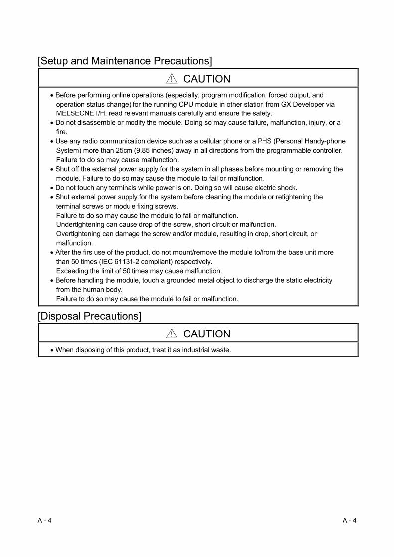
[Setup and Maintenance Precautions]
CAUTION
Before performing online operations (especially, program modification, forced output, and operation status change) for the running CPU module in other station from GX Developer via MELSECNET/H, read relevant manuals carefully and ensure the safety.
Do not disassemble or modify the module. Doing so may cause failure, malfunction, injury, or a fire.
Use any radio communication device such as a cellular phone or a PHS (Personal Handy-phone System) more than 25cm (9.85 inches) away in all directions from the programmable controller. Failure to do so may cause malfunction.
Shut off the external power supply for the system in all phases before mounting or removing the module. Failure to do so may cause the module to fail or malfunction.
Do not touch any terminals while power is on. Doing so will cause electric shock. Shut external power supply for the system before cleaning the module or retightening the
terminal screws or module fixing screws. Failure to do so may cause the module to fail or malfunction. Undertightening can cause drop of the screw, short circuit or malfunction. Overtightening can damage the screw and/or module, resulting in drop, short circuit, or malfunction.
After the firs use of the product, do not mount/remove the module to/from the base unit more than 50 times (IEC 61131-2 compliant) respectively. Exceeding the limit of 50 times may cause malfunction.
Before handling the module, touch a grounded metal object to discharge the static electricity from the human body. Failure to do so may cause the module to fail or malfunction.
[Disposal Precautions]
CAUTION
When disposing of this product, treat it as industrial waste.
!
!

A - 5 A - 5
• CONDITIONS OF USE FOR THE PRODUCT •
(1) Mitsubishi programmable controller ("the PRODUCT") shall be used in conditions;
i) where any problem, fault or failure occurring in the PRODUCT, if any, shall not lead to any major
or serious accident; and
ii) where the backup and fail-safe function are systematically or automatically provided outside of
the PRODUCT for the case of any problem, fault or failure occurring in the PRODUCT.
(2) The PRODUCT has been designed and manufactured for the purpose of being used in general
industries.
MITSUBISHI SHALL HAVE NO RESPONSIBILITY OR LIABILITY (INCLUDING, BUT NOT
LIMITED TO ANY AND ALL RESPONSIBILITY OR LIABILITY BASED ON CONTRACT,
WARRANTY, TORT, PRODUCT LIABILITY) FOR ANY INJURY OR DEATH TO PERSONS OR
LOSS OR DAMAGE TO PROPERTY CAUSED BY the PRODUCT THAT ARE OPERATED OR
USED IN APPLICATION NOT INTENDED OR EXCLUDED BY INSTRUCTIONS, PRECAUTIONS,
OR WARNING CONTAINED IN MITSUBISHI'S USER, INSTRUCTION AND/OR SAFETY
MANUALS, TECHNICAL BULLETINS AND GUIDELINES FOR the PRODUCT.
("Prohibited Application")
Prohibited Applications include, but not limited to, the use of the PRODUCT in;
Nuclear Power Plants and any other power plants operated by Power companies, and/or any other
cases in which the public could be affected if any problem or fault occurs in the PRODUCT.
Railway companies or Public service purposes, and/or any other cases in which establishment of
a special quality assurance system is required by the Purchaser or End User.
Aircraft or Aerospace, Medical applications, Train equipment, transport equipment such as
Elevator and Escalator, Incineration and Fuel devices, Vehicles, Manned transportation,
Equipment for Recreation and Amusement, and Safety devices, handling of Nuclear or
Hazardous Materials or Chemicals, Mining and Drilling, and/or other applications where there is a
significant risk of injury to the public or property.
Notwithstanding the above, restrictions Mitsubishi may in its sole discretion, authorize use of the
PRODUCT in one or more of the Prohibited Applications, provided that the usage of the PRODUCT
is limited only for the specific applications agreed to by Mitsubishi and provided further that no
special quality assurance or fail-safe, redundant or other safety features which exceed the general
specifications of the PRODUCTs are required. For details, please contact the Mitsubishi
representative in your region.

A - 6 A - 6
REVISIONS The manual number is given on the bottom left of the back cover.
Print Date Manual Number Revision Dec., 1999 SH(NA)-080049-A First printing Oct., 2000 SH(NA)-080049-B Correction
Safety Precautions, Contents, About Manuals, About the Generic Terms and Abbreviations, Chapter 1, Section 1.1, 1.2, Chapter 2, Section 2.1.3, 2.1.4, 2.2.2, 3.1.1, 3.1.2, 3.2, 3.2.1, 3.2.2, 3.3, 3.3.1, 3.3.2, 3.3.3, 4.1, 4.2, 4.3.1, 4.3.2, 4.5, 4.5.1, 4.5.2, 4.5.3, 4.6.1, 4.6.2, 4.7, 4.7.1, 4.7.2, 4.8, 4.8.1, 4.8.2, 4.8.3, 4.8.4, Chapter 5, Section 5.1, 5.2, 5.2.3, 5.2.4, 5.2.5, 5.2.6, 5.5, 5.7, 5.7.1, 5.10, 6.1.2, 6.2, 6.2.1, 6.2.2, 6.2.3, 6.3, Chapter 7, Section 7.2, 7.3.1, 7.4, 7.4.1, 7.4.3, 7.4.5, 7.5, 7.5.3, 7.5.4, 7.5.5, 7.6, 7.7, 7.8, Chapter 8, Section 8.1, 8.1.1, 8.2, 8.2.1, 8.2.2, 8.2.3, 8.2.4, 8.2.5, 8.3, 8.4, Appendix 2.2, 3, 4
Addition
Product Configuration, Section 2.4, 2.5, 2.6, Appendix 1.2, Index
Deletion
Section 2.4
May, 2001 SH(NA)-080049-C Module addition
QJ71LP21G, QJ71LP21GE
Correction
Safety Precautions, Contents, About the Generic Terms and Abbreviations, Section 1.1, 1.2, 2.4, 2.13, 2.1.4, 2.2, 2.2.1, 2.3, 3.1.1, 3.1.3, 3.2, 3.2.2, 3.3.2, 3.3.3, 3.3.4, 4.3.2, 4.4.2, 4.5.1, 4.5.2, 4.5.3, 4.6.2, 4.7.1, 4.7.2, Chapter 5, Section 5.1, 5.2.5, 5.2.6, 5.4, 5.6, 5.7.1, 5.7.2, 5.8, 5.9, 6.1.2, 6.2.1, 6.3, Chapter 7, Section 7.2, 7.3, 7.3.1, 7.4.1, 7.4.2, 7.4.5, 7.5, 7.9, 8.1.1, 8.1.4, 8.3, Appendix 2.1
Addition
Section 2.5
Section number changed
Section 2.5 2.6, 2.6 2.7
June, 2002 SH(NA)-080049-D Module addition
QJ71LP21S-25
Correction
Safety Precautions, Contents, About Manuals, Product Configuration, Section 1.1, 1.2, 2.2, 3.1.1, 3.2.2, 3.3.2, 4.2, 5.2.1, 5.6, 6.2.1, 6.2.2, Chapter 7, Section 7.3, 7.3.2, 7.4.5, 8.3, Appendix 3, 4, Index
Apr., 2003 SH(NA)-080049-E Correction
Safety Precautions, Contents, About Manuals, Section 1.2, 2.1.3, 2.2.2, 2.5, 3.1.1, 3.2.1, 3.2.2, 3.3.1, 3.3.3, Chapter 5, Section 5.2.1, 5.7, 5.7.1, 5.7.2, 5.8, 5.9, 6.1.2, 6.2, 6.4, 7.1, 7.4.2, 7.4.3, 7.4.4, 7.4.5, 7.5, 7.5.4, 7.8, 7.9, 8.1, 8.2, 8.2.1, 8.2.5, 8.3

A - 7 A - 7
The manual number is given on the bottom left of the back cover.
Print Date Manual Number Revision Jun., 2004 SH(NA)-080049-F · The contents of function version D were added.
· The entire manual was reviewed. Oct., 2004 SH(NA)-080049-G Mode addition
MELSECNET/H Extended Mode
Correction
Safety Precautions, Product Configuration, Section 1.1, 1.2, 2.1.2, 2.2, 2.2.2, 2.2.3, 3.1.1, 3.2.1, 3.3.2, 4.2, 4.3.3, 4.6.1, 4.6.2, 4.8.1, Chapter 5, Section 5.1, 5.4, 6.2.2, 6.2.3, 7.4.5, 7.6, 7.10.2, 8.1, 8.1.1, 8.1.2, 8.1.3, 8.2, 8.2.1, 8.2.7, 8.3, Appendix 1.1, 1.2, 3, 4, 5, INDEX
Addition
Section 8.2.5, 8.2.9, 8.2.10
Section number changed
Section 8.2.5 8.2.6, 8.2.6 8.2.7, 8.2.7 8.2.8
Oct., 2005 SH(NA)-080049-H Correction
Safety Precautions, Conformation to the EMC Directive and Low Voltage Instruction, Section 1.1, 1.2, 2.1.2, 2.2, 2.2.1, 2.2.3, 3.1.3, 3.3.2, 4.2, 4.6.1, 4.7.1, 4.7.2, 4.8.1, Chapter 5, Section 5.1, 5.4, Chapter 6, 7, Section 7.3.1, 7.7, 7.10.2, 8.1.2, 8.1.3, 8.2, 8.2.5, 8.3, Appendix 1.1, 1.2, 3, 4, 5
Apr., 2006 SH(NA)-080049-I Correction
Section 2.3, 3.1.2, 4.2, 6.3, 7.4.5, Appendix 4
Oct., 2007 SH(NA)-080049-J Change of a term
"PLC" was changed to "programmable controller".
Correction
About the Generic Terms and Abbreviations, 1.2, 2.1.3, 2.1.4, 2.2, 2.3, 3.2.1, 3.3.2, 3.3.3, 4.2, 4.5.1, 4.5.2, 4.5.3, 4.6.1, 4.7.1, 4.7.2, Chapter 5, 5.1, 5.6, 5.7, 5.7.1, 5.7.2, 6.1.1, 6.2.2, 6.3, 6.4, 7.2, 7.4.5, 7.5.5, 7.10.2, 8.1, 8.2.1, 8.2.4, 8.3, Appendix 3, 4, 5
Addition
DEFINITIONS OF TERMINOLOGY
Jul., 2008 SH(NA)-080049-K Correction
SAFETY PRECAUTIONS, Compliance with the EMC and Low Voltage Directives, About the Generic Terms and Abbreviations, DEFINITIONS OF TERMINOLOGY, Chapter 1, Section 2.1, 2.2, 3.1.1, 3.1.3, 3.2, 3.3.2 to 3.3.4, 4.2, 4.3.4, 4.6.2, 4.7.1, 4.7.2, Chapter 5, Section 5.1, 5.4, 5.6 to 5.9, 6.1.1, 6.3, Chapter 7, Section 7.2, 7.3, 7.4.1, 7.4.2, 7.4.5, 7.5, 7.5.5, 7.7 to 7.9, 7.10.2, 7.10.5, 7.10.7, 8.1, 8.3, Appendix 1.1, 2.1, 3, 4

A - 8 A - 8
The manual number is given on the bottom left of the back cover. Print Date Manual Number Revision Jan., 2009 SH(NA)-080049-L Mode addition
QJ71NT11B
Correction
SAFETY PRECAUTIONS, COMPLIANCE WITH THE EMC AND LOW VOLTAGE DIRECTIVES, GENERIC TERMS AND ABBREVIATIONS, PACKING LIST, Section 1.1 to 1.3, 2.1.1, 2.1.2, 2.1.4, 2.2, 2.2.3, 3.1.1 to 3.1.3, 3.2.2, 3.3.2, 3.3.3, 4.1 to 4.3, 4.5, 4.5.1 to 4.5.3, 4.7.1, 4.7.2, 4.8, 4.8.2, Chapter 5, Section 5.1, 5.2.5, 5.4, 5.7.1, 6.1.1, 6.4, 7.1 to 7.3, 7.4.1, 7.4.2, 7.4.5, 7.5.5, 7.9, 7.10.2, 8.2, 8.2.1 to 8.2.4, 8.3, 8.4, Appendix 1.1, 1.2, 3, 4, INDEX
Addition
Section 3.1.4, 3.1.5, 4.2.1 to 4.2.3, 4.6.3, 4.6.4, 5.2.6, 8.2.6, Appendix 5
Section number changed Section 4.3.3 4.3.2, 4.3.4 4.3.3, 4.3.5 4.3.4, 5.2.6 5.2.7, 8.2.6 8.2.7, 8.2.7 8.2.8, 8.2.8 8.2.9, 8.2.9 8.2.10, 8.2.10 8.2.11, Appendix 5 6
Aug., 2009 SH(NA)-080049-M Correction
Section 1.3, 2.2, 2.3, Chapter 8, Appendix 1.2 Addition
Section 8.3.1
Section number changed
Section 8.3(4) 8.3.2
Sep., 2010 SH(NA)-080049-N Correction
GENERIC TERMS AND ABBREVIATIONS, Section 1.3, 2.2.1, 2.3, 4.2.1, 4.2.2, 4.2.3, 4.3.1, 5.8, 6.4, 7.4.5, 7.5.6, 8.2.4, 8.2.8, 8.2.10, 8.3.2, Appendix 4, 6
Addition
CONDITIONS OF USE FOR THE PRODUCT
May, 2012 SH(NA)-080049-O Correction
SAFETY PRECAUTIONS, COMPLIANCE WITH THE EMC AND LOW VOLTAGE DIRECTIVES, GENERIC TERMS AND ABBREVIATIONS, Section 2.2, 2.3, 3.1.3, 3.1.4, 3.2.2, 3.3.1, 4.2.1, 4.6.2, 5.7, 6.1.1, 6.3, 7.4.5, 7.10.2, 8.3.2, Appendix 3, 6
A - 9 A - 9
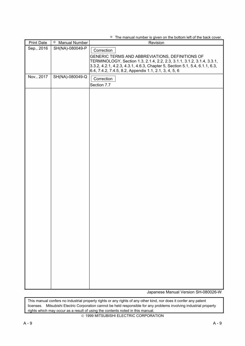
The manual number is given on the bottom left of the back cover. Print Date Manual Number Revision Sep., 2016 SH(NA)-080049-P Correction
GENERIC TERMS AND ABBREVIATIONS, DEFINITIONS OF TERMINOLOGY, Section 1.3, 2.1.4, 2.2, 2.3, 3.1.1, 3.1.2, 3.1.4, 3.3.1, 3.3.2, 4.2.1, 4.2.3, 4.3.1, 4.6.3, Chapter 5, Section 5.1, 5.4, 6.1.1, 6.3, 6.4, 7.4.2, 7.4.5, 8.2, Appendix 1.1, 2.1, 3, 4, 5, 6
Nov., 2017 SH(NA)-080049-Q Correction
Section 7.7
Japanese Manual Version SH-080026-W
This manual confers no industrial property rights or any rights of any other kind, nor does it confer any patent licenses. Mitsubishi Electric Corporation cannot be held responsible for any problems involving industrial property rights which may occur as a result of using the contents noted in this manual.
1999 MITSUBISHI ELECTRIC CORPORATION

A - 10 A - 10
INTRODUCTION
Thank you for purchasing the Mitsubishi Electric MELSEC-Q series programmable controller. Before using the product, please read this manual carefully to develop full familiarity with the functions and performance of the Q series programmable controller to handle the product correctly. Please forward a copy of this manual to the end user.
CONTENTS
SAFETY PRECAUTIONS ............................................................................................................................ A- 1
CONDITIONS OF USE FOR THE PRODUCT ........................................................................................... A- 5
REVISIONS .................................................................................................................................................. A- 6
CONTENTS .................................................................................................................................................. A- 10
MANUALS .................................................................................................................................................... A- 15
COMPLIANCE WITH EMC AND LOW VOLTAGE DIRECTIVES ............................................................. A- 15
GENERIC TERMS AND ABBREVIATIONS ............................................................................................... A- 16
DEFINITIONS OF TERMINOLOGY ............................................................................................................ A- 18
PACKING LIST ............................................................................................................................................ A- 19
1 OVERVIEW 1- 1 to 1-14
1.1 Overview ................................................................................................................................................ 1- 1
1.2 Features ................................................................................................................................................. 1- 4
1.3 Symbols Used in This Manual ............................................................................................................... 1- 14
2 SYSTEM CONFIGURATION 2- 1 to 2-19
2.1 MELSECNET/H Network Configurations .............................................................................................. 2- 1
2.1.1 Single network system .................................................................................................................... 2- 1
2.1.2 Redundant system (Redundant CPU) ............................................................................................ 2- 3
2.1.3 Simple dual-structured system (High Performance model QCPU and Process CPU) ................. 2- 4
2.1.4 Multiple network system (High Performance model QCPU, Process CPU, Redundant CPU,
and Universal model QCPU) .......................................................................................................... 2- 5
2.2 Applicable Systems ................................................................................................................................ 2- 6
2.2.1 Precautions when using link dedicated instructions ....................................................................... 2- 9
2.2.2 Precautions when using network modules in the multiple CPU system ....................................... 2- 11
2.2.3 List of functions for each CPU module ........................................................................................... 2- 17
2.3 Checking Serial Number and Function Version .................................................................................... 2- 18
3 SPECIFICATIONS 3- 1 to 3-52
3.1 Performance Specifications ................................................................................................................... 3- 1
3.1.1 Performance specifications ............................................................................................................. 3- 1
3.1.2 Optical fiber cable specifications .................................................................................................... 3- 5
3.1.3 Coaxial cable specifications ............................................................................................................ 3- 6
3.1.4 Shielded twisted pair cable specifications ...................................................................................... 3- 11
3.1.5 CC-Link Ver. 1.10-compatible cable specifications ........................................................................ 3- 13
3.2 Function Specifications .......................................................................................................................... 3- 14
3.2.1 Cyclic transmission function (periodical communication) .............................................................. 3- 15
3.2.2 RAS function .................................................................................................................................... 3- 18
3.3 Specifications of the Link Data Sending/Receiving Processing Time .................................................. 3- 29
3.3.1 Link data sending/receiving processing ......................................................................................... 3- 29
3.3.2 How to calculate the transmission delay time ................................................................................ 3- 33

A - 11 A - 11
3.3.3 Reducing the link refresh time ........................................................................................................ 3- 47
3.3.4 Reduction of the link scan time ....................................................................................................... 3- 52
3.3.5 Control station shift time .................................................................................................................. 3- 52
4 SETUP AND PROCEDURES BEFORE STARTING THE OPERATION 4- 1 to 4-45
4.1 Procedures Before Starting the Operation ............................................................................................ 4- 1
4.2 Part Names and Settings ....................................................................................................................... 4- 2
4.2.1 QJ71LP21, QJ71LP21-25, QJ71LP21S-25, QJ71LP21G, QJ71LP21GE .................................... 4- 2
4.2.2 QJ71BR11 ....................................................................................................................................... 4- 5
4.2.3 QJ71NT11B ..................................................................................................................................... 4- 7
4.3 Loading and Installation ......................................................................................................................... 4- 8
4.3.1 Handling precautions ...................................................................................................................... 4- 8
4.3.2 Installing and uninstalling the module ............................................................................................. 4- 10
4.3.3 Stopping the CPU module (unintentional output prevention) ........................................................ 4- 11
4.3.4 Checking the input power supply voltage ....................................................................................... 4- 11
4.4 Powering On .......................................................................................................................................... 4- 11
4.4.1 Checking the on status of the POWER LED of the power supply module .................................... 4- 11
4.4.2 Checking the on status of the RUN LED of the network module................................................... 4- 11
4.5 Standalone Check of the Network Module (Offline Tests) ................................................................... 4- 12
4.5.1 Self-loopback test ............................................................................................................................ 4- 13
4.5.2 Internal self-loopback test ............................................................................................................... 4- 15
4.5.3 Hardware test .................................................................................................................................. 4- 17
4.6 Cable Connection .................................................................................................................................. 4- 19
4.6.1 Optical loop system ......................................................................................................................... 4- 19
4.6.2 Coaxial bus system ......................................................................................................................... 4- 22
4.6.3 Twisted bus system (when using a shielded twisted pair cable) ................................................... 4- 27
4.6.4 Twisted bus system (when using CC-Link Ver. 1.10-compatible cable) ....................................... 4- 29
4.7 Offline Tests from GX Developer .......................................................................................................... 4- 30
4.7.1 Station-to-station test ...................................................................................................................... 4- 30
4.7.2 Forward loop/reverse loop test (optical loop system only) ............................................................. 4- 36
4.8 Network Diagnostics from GX Developer (Online Tests) ..................................................................... 4- 41
4.8.1 Loop test (optical loop system only) ............................................................................................... 4- 42
4.8.2 Setup confirmation test (optical loop, coaxial bus system only) .................................................... 4- 43
4.8.3 Station order check test (optical loop system only) ........................................................................ 4- 44
4.8.4 Communication test......................................................................................................................... 4- 45
5 PARAMETER SETTINGS 5- 1 to 5-42
5.1 Setting the Number of Modules (Network Type) .................................................................................. 5- 7
5.2 Network Settings .................................................................................................................................... 5- 9
5.2.1 Starting I/O No. ................................................................................................................................ 5- 9
5.2.2 Network No. ..................................................................................................................................... 5- 9
5.2.3 Total stations ................................................................................................................................... 5- 10
5.2.4 Group No. ........................................................................................................................................ 5- 10
5.2.5 Mode ................................................................................................................................................ 5- 11
5.2.6 Communication speed setting (twisted bus system only) .............................................................. 5- 12

A - 12 A - 12
5.2.7 Example of parameter settings ....................................................................................................... 5- 13
5.3 Common Parameters (Network Range Assignment Screen) .............................................................. 5- 14
5.3.1 Send range for each station (LB/LW settings) ............................................................................... 5- 14
5.3.2 Send range for each station (LX/LY settings) ................................................................................ 5- 15
5.3.3 Specification of the I/O master station ............................................................................................ 5- 16
5.3.4 Specification of the reserved station ............................................................................................... 5- 16
5.3.5 Pairing setting .................................................................................................................................. 5- 16
5.4 Supplementary Settings ......................................................................................................................... 5- 17
5.5 Control Station Return Setting ............................................................................................................... 5- 20
5.6 Station Inherent Parameters (High Performance model QCPU, Process CPU, Redundant CPU,
and Universal model QCPU) ................................................................................................................. 5- 21
5.7 Refresh Parameters ............................................................................................................................... 5- 25
5.7.1 Concept of the link refreshing ......................................................................................................... 5- 28
5.7.2 How to set the refresh parameters ................................................................................................. 5- 30
5.8 Valid Module During Other Station Access ........................................................................................... 5- 39
5.9 Standby Station Compatible Module (High Performance model QCPU and Process CPU) .............. 5- 40
5.10 Writing Parameters to the CPU ........................................................................................................... 5- 42
6 PROGRAMMING 6- 1 to 6-31
6.1 Programming Precautions ..................................................................................................................... 6- 1
6.1.1 Interlock related signals .................................................................................................................. 6- 1
6.1.2 Program example ............................................................................................................................ 6- 4
6.2 Cyclic Transmission ............................................................................................................................... 6- 5
6.2.1 32-bit data assurance ...................................................................................................................... 6- 5
6.2.2 Station-based block data assurance for cyclic data ....................................................................... 6- 7
6.2.3 Interlock program example ............................................................................................................. 6- 8
6.3 Link Dedicated Instruction List ............................................................................................................... 6- 9
6.4 Using the Link Special Relays (SB)/Link Special Registers (SW) ....................................................... 6- 13
7 APPLICATION FUNCTIONS 7- 1 to 7-160
7.1 Direct Access to the Link Devices ......................................................................................................... 7- 2
7.2 Inter-Link Data Transfer Function (High Performance model QCPU, Process CPU,
Redundant CPU, and Universal model QCPU) .................................................................................... 7- 6
7.3 Low-Speed Cyclic Transmission Function (High Performance model QCPU, Process CPU,
Redundant CPU, and Universal model QCPU) .................................................................................... 7- 9
7.3.1 Send range settings ........................................................................................................................ 7- 10
7.3.2 Send timing ...................................................................................................................................... 7- 11
7.3.3 Startup ............................................................................................................................................. 7- 14
7.4 Transient Transmission Function (Non-Periodical Communication).................................................... 7- 16
7.4.1 Communication function.................................................................................................................. 7- 17
7.4.2 Routing function ............................................................................................................................... 7- 20
7.4.3 Group function ................................................................................................................................. 7- 27
7.4.4 Message sending function using the logical channel numbers ..................................................... 7- 28
7.4.5 Programming ................................................................................................................................... 7- 30
7.4.5 (1) Data sending/receiving (JP/GP.SEND, JP/GP.RECV) ............................................................ 7- 36
7.4.5 (2) Reading from/writing to word devices of other stations (JP/GP.READ, JP/GP.SREAD,
JP/GP.WRITE, JP/GP.SWRITE) .................................................................................................... 7- 53

A - 13 A - 13
7.4.5 (3) Requesting transient transmission to other stations (J(P)/G(P).REQ) .................................... 7- 72
7.4.5 (4) Reading/writing word devices of other stations (J(P).ZNRD, J(P).ZNWR) .............................. 7- 82
7.4.5 (5) Remote RUN/Remote STOP (Z(P).RRUN, Z(P).RSTOP) ....................................................... 7- 91 7.4.5 (6) Reading and writing clock data of other station CPU modules (Z(P).RTMRD, Z(P).RTMWR)
......................................................................................................................................................... 7- 100
7.4.6 Setting the clock to stations on a network with GX Developer ...................................................... 7- 109
7.5 Starting the Interrupt Sequence Program ............................................................................................. 7- 110
7.5.1 Interrupt setting parameters ............................................................................................................ 7- 111
7.5.2 Interrupts using the RECVS instruction .......................................................................................... 7- 113
7.5.3 Interrupts by the link devices (LB/LW/LX) for cyclic transmission ................................................. 7- 114
7.5.4 Interrupts by the link special device (SB/SW) ................................................................................ 7- 116
7.5.5 Message reception "one scan completion" instruction (Z.RECVS) ............................................... 7- 117
7.5.6 Application example ........................................................................................................................ 7- 121
7.6 Multiplex Transmission Function (Optical Loop System) ..................................................................... 7- 123
7.7 Simple Dual-Structured Network (High Performance model QCPU and Process CPU) .................... 7- 124
7.8 Stopping/Restarting the Cyclic Transmission and Stopping Link Refreshing (Network Test) ............ 7- 129
7.9 Increasing the Number of Send Points by Installing Multiple Modules with the Same Network
(High Performance model QCPU, Process CPU, Redundant CPU, and Universal model QCPU) ... 7- 132
7.10 Configuring a Network with a Redundant System .............................................................................. 7- 134
7.10.1 Outline of the redundant system operation .................................................................................. 7- 134
7.10.2 Precautions for network configuration including a redundant system ......................................... 7- 137
7.10.3 Pairing setting in a redundant system .......................................................................................... 7- 145
7.10.4 Redundant settings in a redundant system .................................................................................. 7- 149
7.10.5 System switching request to the control system CPU ................................................................. 7- 150
7.10.6 Function for returning to control station in a redundant system .................................................. 7- 152
7.10.7 Data retention time for system switching ...................................................................................... 7- 153
7.10.8 Routing via a redundant system ................................................................................................... 7- 159
8 TROUBLESHOOTING 8- 1 to 8-53
8.1 Network Diagnostics (Network Monitor) ................................................................................................ 8- 2
8.1.1 Host information .............................................................................................................................. 8- 5
8.1.2 Other station information ................................................................................................................. 8- 7
8.1.3 Network monitor details ................................................................................................................... 8- 11
8.1.4 Error history monitor ........................................................................................................................ 8- 15
8.2 Troubleshooting ..................................................................................................................................... 8- 18
8.2.1 Items to be checked first ................................................................................................................. 8- 23
8.2.2 Data link failure on the entire system ............................................................................................. 8- 24
8.2.3 Data link failure caused by reset or power-off of each station ....................................................... 8- 24
8.2.4 Data link failure of a specific station ............................................................................................... 8- 25
8.2.5 Data link failure in MELSECNET/H Extended mode ..................................................................... 8- 25
8.2.6 Data link failure in MELSECNET/H twisted bus system ................................................................ 8- 26
8.2.7 Data link in a redundant system ..................................................................................................... 8- 26
8.2.8 Send/received data failure .............................................................................................................. 8- 27
8.2.9 Link dedicated instruction not complete ......................................................................................... 8- 28
8.2.10 Checking online for reverse optical fiber cable connection ......................................................... 8- 29
8.2.11 When different network types exist in the same network ............................................................ 8- 31
8.3 Error Codes ............................................................................................................................................ 8- 32
8.3.1 How to check error codes ............................................................................................................... 8- 32
A - 14 A - 14
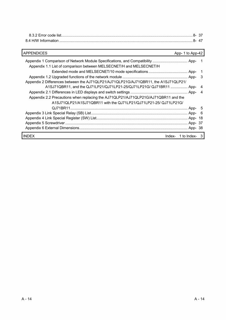
8.3.2 Error code list................................................................................................................................... 8- 37
8.4 H/W Information ..................................................................................................................................... 8- 47
APPENDICES App- 1 to App-42
Appendix 1 Comparison of Network Module Specifications, and Compatibility ................................... App- 1
Appendix 1.1 List of comparison between MELSECNET/H and MELSECNET/H
Extended mode and MELSECNET/10 mode specifications ....................................... App- 1
Appendix 1.2 Upgraded functions of the network module ................................................................. App- 3 Appendix 2 Differences between the AJ71QLP21/AJ71QLP21G/AJ71QBR11, the A1SJ71QLP21/
A1SJ71QBR11, and the QJ71LP21/QJ71LP21-25/QJ71LP21G/ QJ71BR11 ................. App- 4
Appendix 2.1 Differences in LED displays and switch settings ......................................................... App- 4
Appendix 2.2 Precautions when replacing the AJ71QLP21/AJ71QLP21G/AJ71QBR11 and the
A1SJ71QLP21/A1SJ71QBR11 with the QJ71LP21/QJ71LP21-25/ QJ71LP21G/
QJ71BR11 ..................................................................................................................... App- 5 Appendix 3 Link Special Relay (SB) List ................................................................................................ App- 6 Appendix 4 Link Special Register (SW) List ........................................................................................... App- 18 Appendix 5 Screwdriver .......................................................................................................................... App- 37 Appendix 6 External Dimensions ............................................................................................................ App- 38
INDEX Index- 1 to Index- 3

A - 15 A - 15
MANUALS
The following manuals are also relevant to this product. Order each manual as needed, referring to the following list.
Relevant manuals
Manual name Manual number
(Model code)
Q corresponding MELSECNET/H Network System Reference Manual (Remote I/O network)
Specifications, setup and procedures before starting the operation, parameter setting, programming and
troubleshooting of the remote I/O network of the MELSECNET/H network system. (Sold separately)
SH-080124 (13JF96)
Type MELSECNET/10 Network system (PLC to PLC network) Reference Manual
System configuration, performance, specifications and programming of MELSECNET/10 network system
(PLC to PLC network). (Sold separately)
IB-66440 (13JE33)
For QnA/Q4AR MELSECNET/10 Network System Reference Manual
System configuration, performance, specifications and programming of MELSECNET/10 network system
(PLC to PLC network). (Sold separately)
IB-66690 (13JF78)
COMPLIANCE WITH EMC AND LOW VOLTAGE DIRECTIVES
(1) Method of ensuring compliance To ensure that Mitsubishi Electric programmable controllers maintain EMC and Low Voltage Directives when incorporated into other machinery or equipment, certain measures may be necessary. Please refer to one of the following manuals. • QCPU User's Manual (Hardware Design, Maintenance and Inspection)
• Safety Guidelines (This manual is included with the CPU module or base unit.)
The CE mark on the side of the programmable controller indicates compliance with EMC and Low Voltage Directives.
(2) Additional measures
(a) When using QJ71LP21 and QJ71NT11B No additional measures are necessary for the compliance of this product with EMC and Low Voltage Directives.
(b) When using QJ71BR11 To ensure that this product maintains EMC and Low Voltage Directives, please refer to one of the manuals listed under (1).
A - 16 A - 16
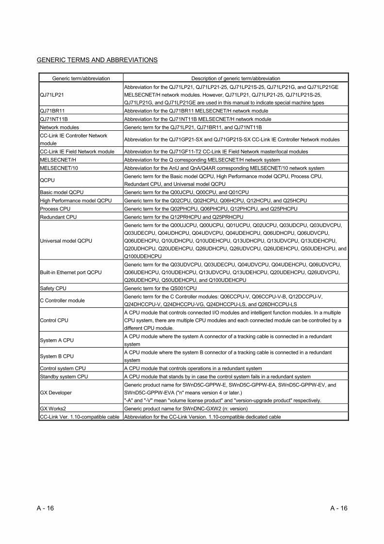
GENERIC TERMS AND ABBREVIATIONS
Generic term/abbreviation Description of generic term/abbreviation
QJ71LP21
Abbreviation for the QJ71LP21, QJ71LP21-25, QJ71LP21S-25, QJ71LP21G, and QJ71LP21GE
MELSECNET/H network modules. However, QJ71LP21, QJ71LP21-25, QJ71LP21S-25,
QJ71LP21G, and QJ71LP21GE are used in this manual to indicate special machine types
QJ71BR11 Abbreviation for the QJ71BR11 MELSECNET/H network module
QJ71NT11B Abbreviation for the QJ71NT11B MELSECNET/H network module
Network modules Generic term for the QJ71LP21, QJ71BR11, and QJ71NT11B
CC-Link IE Controller Network
module Abbreviation for the QJ71GP21-SX and QJ71GP21S-SX CC-Link IE Controller Network modules
CC-Link IE Field Network module Abbreviation for the QJ71GF11-T2 CC-Link IE Field Network master/local modules
MELSECNET/H Abbreviation for the Q corresponding MELSECNET/H network system
MELSECNET/10 Abbreviation for the AnU and QnA/Q4AR corresponding MELSECNET/10 network system
QCPU Generic term for the Basic model QCPU, High Performance model QCPU, Process CPU,
Redundant CPU, and Universal model QCPU
Basic model QCPU Generic term for the Q00JCPU, Q00CPU, and Q01CPU
High Performance model QCPU Generic term for the Q02CPU, Q02HCPU, Q06HCPU, Q12HCPU, and Q25HCPU
Process CPU Generic term for the Q02PHCPU, Q06PHCPU, Q12PHCPU, and Q25PHCPU
Redundant CPU Generic term for the Q12PRHCPU and Q25PRHCPU
Universal model QCPU
Generic term for the Q00UJCPU, Q00UCPU, Q01UCPU, Q02UCPU, Q03UDCPU, Q03UDVCPU,
Q03UDECPU, Q04UDHCPU, Q04UDVCPU, Q04UDEHCPU, Q06UDHCPU, Q06UDVCPU,
Q06UDEHCPU, Q10UDHCPU, Q10UDEHCPU, Q13UDHCPU, Q13UDVCPU, Q13UDEHCPU,
Q20UDHCPU, Q20UDEHCPU, Q26UDHCPU, Q26UDVCPU, Q26UDEHCPU, Q50UDEHCPU, and
Q100UDEHCPU
Built-in Ethernet port QCPU
Generic term for the Q03UDVCPU, Q03UDECPU, Q04UDVCPU, Q04UDEHCPU, Q06UDVCPU,
Q06UDEHCPU, Q10UDEHCPU, Q13UDVCPU, Q13UDEHCPU, Q20UDEHCPU, Q26UDVCPU,
Q26UDEHCPU, Q50UDEHCPU, and Q100UDEHCPU
Safety CPU Generic term for the QS001CPU
C Controller module Generic term for the C Controller modules: Q06CCPU-V, Q06CCPU-V-B, Q12DCCPU-V,
Q24DHCCPU-V, Q24DHCCPU-VG, Q24DHCCPU-LS, and Q26DHCCPU-LS
Control CPU
A CPU module that controls connected I/O modules and intelligent function modules. In a multiple
CPU system, there are multiple CPU modules and each connected module can be controlled by a
different CPU module.
System A CPU A CPU module where the system A connector of a tracking cable is connected in a redundant
system
System B CPU A CPU module where the system B connector of a tracking cable is connected in a redundant
system
Control system CPU A CPU module that controls operations in a redundant system
Standby system CPU A CPU module that stands by in case the control system fails in a redundant system
GX Developer
Generic product name for SWnD5C-GPPW-E, SWnD5C-GPPW-EA, SWnD5C-GPPW-EV, and
SWnD5C-GPPW-EVA ("n" means version 4 or later.)
"-A" and "-V" mean "volume license product" and "version-upgrade product" respectively.
GX Works2 Generic product name for SWnDNC-GXW2 (n: version)
CC-Link Ver. 1.10-compatible cable Abbreviation for the CC-Link Version. 1.10-compatible dedicated cable

A - 17 A - 17
Generic term/abbreviation Description of generic term/abbreviation
SEND Abbreviation for JP.SEND and GP.SEND
RECV Abbreviation for JP.RECV and GP.RECV
READ Abbreviation for JP.READ and GP.READ
SREAD Abbreviation for JP.SREAD and GP.SREAD
WRITE Abbreviation for JP.WRITE and GP.WRITE
SWRITE Abbreviation for JP.SWRITE and GP.SWRITE
REQ Abbreviation for J.REQ, JP.REQ, G.REQ and GP.REQ
ZNRD Abbreviation for J.ZNRD and JP.ZNRD
ZNWR Abbreviation for J.ZNWR and JP.ZNWR
RRUN Abbreviation for Z.RRUN and ZP.RRUN
RSTOP Abbreviation for Z.RSTOP and ZP.RSTOP
RTMRD Abbreviation for Z.RTMRD and ZP.RTMRD
RTMWR Abbreviation for Z.RTMWR and ZP.RTMWR
RECVS Abbreviation for Z.RECVS

A - 18 A - 18
DEFINITIONS OF TERMINOLOGY
Term Description
Cyclic transmission A function by which data are periodically exchanged among stations on the network using
link devices
Transient transmission A function of communication with another station, which is used when requested by a
dedicated instruction or GX Developer
Link dedicated instruction Dedicated instruction used for transient transmission.
RAS Abbreviation for Reliability, Availability, and Serviceability.
This term is used to express the overall usability of automation systems.
Control station Only one station that controls the network to which it is connected.
Each station's send range for cyclic transmission is assigned to the control station.
Normal station Station that performs cyclic transmission according to the range assignment of the control
station.
Reserved station
Station that is not actually connected to the network.
It must be included in the total number of stations in the network, since it is to be connected
in the future.
Relay station A station that includes two or more network modules. Data are passed through this station
to stations on other networks.
Reconnection Processing of restarting data link when a faulty station becomes normal.
Disconnection Processing of stopping data link when a data link error occurs.
Device Devices (X, Y, M, D, etc.) that are contained in a CPU module.
Link Device Devices (LB/LW/LX/LY) that are contained in a network module.
Link scan time
Time required for data of each station to be sent in order and to make one rotation in the
network.
The link scan time changes depending on the data volume or transient transmission
request.
Link scans are performed "asynchronously" with sequence scans of the CPU module.
Link refresh
Processing of data transfer between link devices of the network module and CPU module
devices.
Link refresh is performed in "END processing" of the sequence scan of the CPU module.
Buffer memory Memory area in an intelligent function module, in which data are temporarily stored.
The network module does not have any buffer memory area that is offered to the user.
Baton pass A control mechanism in which transmission right (token) is passed around the network for
data transmission.
Control station shift time Time taken from when the control station went down due to a reason such as power-off
until data link is started by the sub-control station.
Group No.
Number that is assigned for transient transmission to any given stations.
By specifying a group of stations as transient transmission target, data can be sent to the
stations of the same group No.
A - 19 A - 19
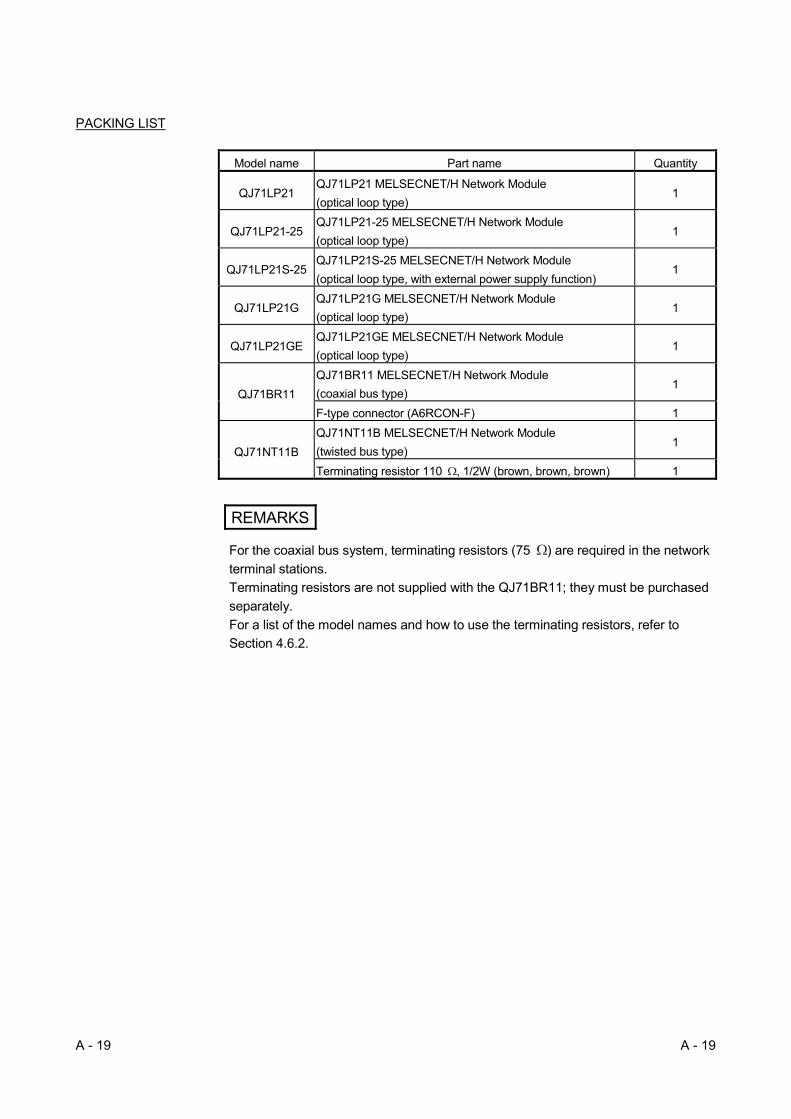
PACKING LIST
Model name Part name Quantity
QJ71LP21 QJ71LP21 MELSECNET/H Network Module
(optical loop type) 1
QJ71LP21-25 QJ71LP21-25 MELSECNET/H Network Module
(optical loop type) 1
QJ71LP21S-25 QJ71LP21S-25 MELSECNET/H Network Module
(optical loop type, with external power supply function) 1
QJ71LP21G QJ71LP21G MELSECNET/H Network Module
(optical loop type) 1
QJ71LP21GE QJ71LP21GE MELSECNET/H Network Module
(optical loop type) 1
QJ71BR11
QJ71BR11 MELSECNET/H Network Module
(coaxial bus type) 1
F-type connector (A6RCON-F) 1
QJ71NT11B
QJ71NT11B MELSECNET/H Network Module
(twisted bus type) 1
Terminating resistor 110 , 1/2W (brown, brown, brown) 1
REMARKS
For the coaxial bus system, terminating resistors (75 ) are required in the network
terminal stations.
Terminating resistors are not supplied with the QJ71BR11; they must be purchased
separately.
For a list of the model names and how to use the terminating resistors, refer to
Section 4.6.2.

1 - 1 1 - 1
MELSEC-Q 1 OVERVIEW
1 OVERVIEW
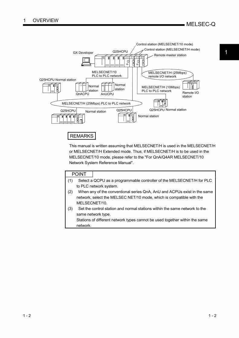
The MELSECNET/H network system includes a PLC to PLC network for
communicating between the control station and normal stations, and a remote I/O
network for communicating between the remote master station and remote I/O stations.
This manual is used for configuring PLC to PLC networks on MELSECNET/H network
systems (hereinafter abbreviated as MESECNET/H.)
When configuring a remote I/O network using MELSECNET/H, refer to Q
corresponding MELSECNET/H Network System Reference Manual (Remote I/O
network).
REMARKS
Networks known as MELSECNET/10H are hereinafter abbreviated as
MELSECNET/H.
1.1 Overview
The PLC to PLC network system of MELSECNET/H provides more functionality,
higher processing speed and more capacity than the conventional PLC to PLC network
system of MELSECNET/10 network system.
In addition, in pursuit of the maximum ease of use of the MELSECNET/10 network
system, the FA system can be networked easily by combining with GX Developer.
The MELSECNET/H system supports the MELSECNET/H and MELSECNET/H
Extended modes (high functionality and high-speed mode) and the MELSECNET/10
mode (functional and performance compatibility mode) to achieve the network
performance improvement and upward compatibility of MELSECNET/10.
Unless otherwise categorized, this is abbreviated as MELSECNET/H for explanatory
purposes in this manual.
1
1 - 2 1 - 2
MELSEC-Q 1 OVERVIEW
Q25HCPUGX DeveloperRemote master station
Control station (MELSECNET/H mode)
MELSECNET/10 PLC to PLC network
MELSECNET/H (25Mbps) remote I/O network
Q25HCPU Normal station
Q25HCPU Q25HCPUNormal station
Normal station
Remote I/O station
MELSECNET/H (10Mbps) PLC to PLC network
Q25HCPU Normal station
Control station (MELSECNET/10 mode)
AnUCPUQnACPU
Normal station
Normal station
MELSECNET/H (25Mbps) PLC to PLC network
REMARKS
This manual is written assuming that MELSECNET/H is used in the MELSECNET/H
or MELSECNET/H Extended mode. Thus, if MELSECNET/H is to be used in the
MELSECNET/10 mode, please refer to the "For QnA/Q4AR MELSECNET/10
Network System Reference Manual".
POINT
(1) Select a QCPU as a programmable controller of the MELSECNET/H for PLC
to PLC network system.
(2) When any of the conventional series QnA, AnU and ACPUs exist in the same
network, select the MELSEC NET/10 mode, which is compatible with the
MELSECNET/10.
(3) Set the control station and normal stations within the same network to the
same network type.
Stations of different network types cannot be used together within the same
network.
1

1 - 3 1 - 3
MELSEC-Q 1 OVERVIEW
The table below shows the CPU modules that can be combined for use on each
network.
CPU
module
Type of networks that can
be used with CPU
Network to be connected
MELSECNET/10 MELSECNET/H
PLC to PLC network PLC to PLC network
QCPU
MELSECNET/H
(10 Mbps)
(MESLECNET/10 mode)
(MESLECNET/H mode,
MELSECNET/H Extended mode)
MELSECNET/H
(25 Mbps)
MELSECNET/H
(Twisted bus)
AnUCPU MELSECNET/10
QnACPU MELSECNET/10
: Use possible : Use not possible
REMARKS
What is network type?
The network type is a parameter set for specifying the network where the network
module is used.
Set the network type of the network module in the Network parameter of GX
Developer.
There are the following network types.
Network type Description
MELSECNET/H mode Set this mode when all CPUs within the network are QCPUs.
MELSECNET/H Extended
mode
The maximum number of link points per station has been increased
compared with the MELSECNET/H mode.
In excess of 2000 bytes, a maximum of 35840 bytes can be set.
Set this mode when the system uses many link points per station.
MELSECNET/10 mode This mode is used to operate the network module on a
MELSECNET/10 network where the QnA/AnU exists.

1 - 4 1 - 4
MELSEC-Q 1 OVERVIEW
1.2 Features
The MELSECNET/H is designed to provide higher processing speed, more capacity,
and more functionality while maintaining the connectivity with the MELSECNET/10; it is
easier to use than ever in combination with GX Developer. Furthermore, the
MELSECNET/H has the following features that were not available with the conventional
MELSECNET (II) and MELSECNET/B data link systems. (1) Achievement of a high-speed communication system
(a) The MELSECNET/H enables high-speed communications with 25Mbps and 10Mbps communication speeds. Communication speeds vary depending on the network system.
Network system Communication speed
Optical loop 10Mbps or 25Mbps 1
Coaxial bus 10Mbps
Twisted bus 156kbps to 10Mbps
1: QJ71LP21-25 and QJ71LP21S-25 only (b) The link scan time has become even faster through the use of processors
specifically designed for linking. (c) Refresh parameter area can be subdivided
By subdividing ranges refresh parameter ranges, refreshing of the areas not used for the sequence program can be eliminated and the refresh time can be reduced by refreshing only those required. (Refer to Section 5.7 "Refresh Parameters.") The number of refresh parameter settings per module is shown below.
Item
Number of settings
Basic model QCPU
Safety CPU
Q00UJCPU
Q00UCPU
Q01UCPU
High Performance model QCPU
Process CPU
Redundant CPU
Universal model QCPU other than listed in the left column.
Link device transfer 8 16 64
SB/SW transfer 1 for each
Also, because the bus speed between a QCPU and a network module has
been improved, the refresh time has been reduced. Network module link device (LB)
Refresh range
QCPU device (B)
Station No. 1(Host)
Station No. 2
Station No. 3
Each station's total send range
Fragmentation
High-speed bus
(d) The optical loop system enables even faster levels of data communication with multiplex transmission (refer to Multiplex Transmission Function in section 7.6.)

1 - 5 1 - 5
MELSEC-Q 1 OVERVIEW
(2) Large-scale and flexible system configuration
(a) The link device has a larger capacity: 16384 points for the link relay (LB) and 16384 points for the link register (LW). (Refer to Section 3.1.1)
(b) The maximum number of link points per station has been increased.
By selecting the network type, the maximum number of link points per station can be increased. 1) MELSECNET/H Extended mode 1
By selecting the MELSECNET/H Extended mode as the network type, the maximum number of link points per station can be set up to 35840 bytes in excess of 2000 bytes. It is not necessary to install multiple network modules for a single CPU module to increase the number of transmission points.
2) MELSECNET/H mode 1 By selecting the MELSECNET/H mode as the network type, the maximum number of link points per station can be set up to 2000 bytes. Furthermore, by installing multiple network modules with the same network number for the same CPU module, the link points of "number of modules maximum number of link points per station" can be sent. (High Performance model QCPU, Process CPU, Redundant CPU, and Universal model QCPU) (Refer to Section 7.9 "Increasing the Number of Send Points by Installing Multiple Modules Having the Same Network Number.")
1: The link scan time varies depending on the network type. Refer to Section 3.3.2 for details.
(c) The commands for transmitting and receiving data with other stations on
the MELSECNET/H network system (SEND, RECV, RECVS, READ, SREAD, WRITE, SWRITE) enable a maximum of 960 words of data to be transmitted and received (refer to Programming in section 7.4.5.)
(d) A system can be expanded to contain a maximum of 239 networks. (Refer
to Section 2.1.4, "A Network System Containing Multiple Networks.")
(e) By using the inter-link data transfer function, data (LB/LW) can be transferred to another network without creating a sequence program. (High Performance model QCPU, Process CPU, Redundant CPU, and Universal model QCPU) (Refer to Section 7.2, "Inter-link Data Transfer Function.")
Network No. 1 Network No. 2
Network module
Network module
3FFFH
00
Inter-link data transfer
LB LBQ25HCPU
Network module 1
Network module 2
Data of network No. 2Data of network No. 1
3FFFH
Q25H CPU
Q25H CPU

1 - 6 1 - 6
MELSEC-Q 1 OVERVIEW
(f) By installing multiple network modules, N:N communication (transient
transmission) with destination stations on eight network systems that use
the programmable controllers as relay stations can be performed using the
routing function.
(Refer to Section 7.4.2, "Routing Function.")
Transient transmission using the routing function can be performed not only
in a system composed of MELSECNET/H networks but also in a system
that contains CC-Link IE Controller Network, CC-Link IE Field Network
and/or MELSECNET/10 networks.
QJ71
LP21
QJ71
LP21
QJ71
LP21
QJ71
LP21
QJ71
LP21
QJ71
LP21
QJ71
LP21
QJ71
LP21
QJ71
LP21
QJ71
LP21
QJ71
LP21
QJ71
LP21
QJ71
LP21
QJ71
LP21
QJ71
LP21
QJ71
LP21
MELSECNET/H MELSECNET/H
MELSECNET/H MELSECNET/H
MELSECNET/HMELSECNET/H
MELSECNET/HMELSECNET/H
No.1
No.2
No.3
No.4
No.5No.6
No.7No.8
Transient transmission
possible.
GX Developer
Request destination
Request
source
Q25H
CPU
Q25H
CPU
Q25H
CPU
Q25H
CPU
Q25H
CPU
Q25H
CPU
Q25H
CPU
Q25H
CPU
Q25H
CPU
: Only the High Performance model QCPU, Process CPU, Redundant
CPU, and Universal model QCPU accept multiple network modules.
(g) The following three types of network systems can be configured
according to applications of each user.
1) Loop system that is more resistant to noise and provides longer distance
in total and between stations. (Up to 30km in total length)
2) Coaxial bus system that allows easier wiring (Up to 500m in total length)
3) Twisted bus system that allows the use of general-purpose cables (Up to
1200m in total length)
(Refer to Section 3.1, "Performance Specifications.")
(h) The following functions facilitate network connection:
1) Any station to be connected in the future can be specified as a reserved
station.
Specifying a station not actually connected as a reserved station
prevents a communication error. (Refer to Section 5.3.4 "Specification of
the reserved station.")
2) It is not necessary to connect stations in order of the station Nos. in the
network. (Refer to Section 4.2 "Part Names and Settings.")
1 - 7 1 - 7
MELSEC-Q 1 OVERVIEW
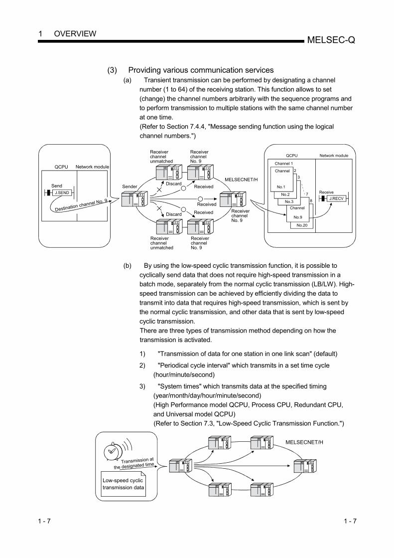
(3) Providing various communication services
(a) Transient transmission can be performed by designating a channel
number (1 to 64) of the receiving station. This function allows to set
(change) the channel numbers arbitrarily with the sequence programs and
to perform transmission to multiple stations with the same channel number
at one time.
(Refer to Section 7.4.4, "Message sending function using the logical
channel numbers.")
MELSECNET/H
Sender
Receiver channel No. 9
Receiver channel No. 9
Receiver channel unmatched
Discard
DiscardReceived
Received
Received
Receiver channel unmatched
Receiver channel No. 9
Network moduleQCPU
J.SEND
Send
Destination channel No. 9
QCPU Network module
No.20
8
7
No.3
3
No.1
Channel
Channel 1
No.9
Channel
No.2
2
J.RECV
Receive
(b) By using the low-speed cyclic transmission function, it is possible to
cyclically send data that does not require high-speed transmission in a
batch mode, separately from the normal cyclic transmission (LB/LW). High-
speed transmission can be achieved by efficiently dividing the data to
transmit into data that requires high-speed transmission, which is sent by
the normal cyclic transmission, and other data that is sent by low-speed
cyclic transmission.
There are three types of transmission method depending on how the
transmission is activated.
1) "Transmission of data for one station in one link scan" (default) 2) "Periodical cycle interval" which transmits in a set time cycle
(hour/minute/second) 3) "System times" which transmits data at the specified timing
(year/month/day/hour/minute/second)
(High Performance model QCPU, Process CPU, Redundant CPU,
and Universal model QCPU)
(Refer to Section 7.3, "Low-Speed Cyclic Transmission Function.")
MELSECNET/H
Transmission at
the designated time
Low-speed cyclic transmission data

1 - 8 1 - 8
MELSEC-Q 1 OVERVIEW
(c) The interrupt sequence program of the host's CPU module can be started
up using the event issue function. This function reduces the response time of the system and process real-time data receiving. (Refer to Section 7.5, "Starting Up the Interrupt Sequence Program.")
END
MAIN
I50
CPU module Network module
Transient transmission from other station
Cyclic transmission
MELSECNET/H
Normal sequence program
Condition check
Interrupt condition parameters• Relay information• Register data• Arrival at a channel• Network status
Conditionsmatched
Interrupt sequence program
IRET
(4) Enhanced RAS functions (Refer to Section 3.2.2, "RAS function.") (a) By using the control station switch function, if the control station of the
network is down, a normal station is substituted for the control station, enabling to continue the network communication.
(b) When a faulty station recovers and can resume normal operation, it
automatically returns to the network to resume the data communication using the automatic return function.
(c) The automatic return control function allows a failed control station to be
reconnected to the network as a normal station, reducing network downtime.
(d) The loopback function (in the optical loop system) isolates a faulty part, where a fault such as cable disconnection or a station error has occurred, and enables data communications among operable stations.
(e) Preventing station failure using external power supply
When two or more stations are faulty and halted in the optical loop system, stations between these faulty stations can continue the data link. Because the loop back is prevented, the link scan time will be stabilized. (The QJ71LP21S-25 is the network module where external power can be supplied.)

1 - 9 1 - 9
MELSEC-Q 1 OVERVIEW
(f) By using the station detach function (coaxial bus system and twisted bus
system), even when some of the connected stations are down due to power off, etc., the normal communication can be continued among other operational stations.
(g) When an error occurs in a normal network due to disconnection, etc. the
data link can be continued by switching to link data refresh on the standby network if two network modules, a regular module and a standby module, are installed for each programmable controller CPU (High Performance model QCPU and Process CPU)
(h) The network module can continue the transient transmission even if an
error that stops the CPU module while the system is operating occurs.
(i) It is possible to check the time when a transient error occurred.
REMARKS
The following faults make the RAS functions valid. Break in cable Power-off of slave station Network setting error Fault detectable by self-diagnostics of CPU module If the network module has become faulty, the RAS functions may not be activated depending on the fault.

1 - 10 1 - 10
MELSEC-Q 1 OVERVIEW
(5) Enhancement and compatibility of the network functions
(a) Because of the 32-bit data assurance, data with double word precision
(32 bits) can be assured without an interlock.
(Refer to Section 6.2.1, "32-bit data assurance.")
Network module LW
CPU module device W
Refresh A
Refresh B
Updated part of refresh A Positional data 1 lower
higher
Refresh C
Updated part of refresh B
Updated part of refresh C
Link refresh in 32-bit units
Positional data 2 lower
higher
Positional data 9 lower
higher
Positional data 10 lower
higher
(b) Through the station-based block data assurance for cyclic data, it is
possible to manipulate multiple word data without interlocks.
(Refer to Section 6.2.2, "Station-based block data assurance for cyclic
data.")
Network module LW
CPU module device W
Updated part of refresh A
Station No. 1
Station No. 2(Host)
Station No. 3
Station No. 4
Updated part of refresh B
Updated part of refresh C
Refresh A
Refresh B
Refresh C
(c) In the network debug mode, the network functions of user programs can
be tested in the online environment without affecting systems being
operated.
(Refer to Section 5.2.5, "Mode.")
MELSECNET/H
Systems being operated
Being debuggedGX Developer
Datareceivepossible
LB/LW

1 - 11 1 - 11
MELSEC-Q 1 OVERVIEW
(d) By using the MELSECNET/10 mode (functional compatibility and
performance compatibility mode), the MELSECNET/H can be used
together with the conventional network modules to easily install a
programmable Controller Network system.
To use the MELSECNET/H in the MELSECNET/10 mode (functional
compatibility and performance compatibility mode), please refer to the "For
QnA/Q4AR MELSECNET/10 Network System Reference Manual".
MELSECNET/H
MELSECNET/10
QCPU QCPU QCPU QCPUA2USCPU
QnACPU
(6) Increased ease of network configuration in combination with GX Developer
(a) The network parameters can easily be set by visualizing pull-down menus,
dialogue boxes, etc.
(b) The settings of network Nos., group numbers and operation modes have
been simplified so that these values can be specified only through software
settings.
(c) On the twisted bus system, the transmission speed setting for the normal
station is not required.
The normal station operates with the transmission speed set to the control
station.
(Refer to Section 5.2.6, "Communication speed setting.")
(Network parameters) Pull-down menu
Simplified

1 - 12 1 - 12
MELSEC-Q 1 OVERVIEW
(c) Troubleshooting process has been simplified through system monitoring.
(System monitor/error code display)
Displays the latest error code.
Displays error history.
Displays the description and corrective action of the error code selected in error history.
(d) After assigning the refresh parameters and inter-link data transfer devices
to a network system in which multiple network modules are installed,
duplicate device settings can easily be checked with [Assignment image
diagram].

1 - 13 1 - 13
MELSEC-Q 1 OVERVIEW
(7) Redundant system configuration
(a) Network modules can be dualized.
A system containing a network module can be dualized (redundant system)
by installing another network module and using redundant CPUs.
In case of an error in the control system CPU or a network module, the
redundant system including double network modules switches the control
system to the standby system, allowing system control and data linking to
be continued on the standby system. (Refer to Section 7.10.1.)
(b) Automatically issuing system switching request to the control system CPU
If failure of a network module mounted to the control system CPU of the
redundant system or a data link error is detected, a system switching
request will be automatically issued to the CPU. (Refer to Section 7.10.5.)
(c) Transient transmission to redundant system is available.
By transient transmission using special link instructions or GX Developer,
device data can be read from or written to the host system, control/standby
system, or system A/B in the redundant system, and remote RUN/STOP
can be executed. (Refer to Section 7.4.5.)
When the redundant system is a target station, even if system switching
occurs, the target can be followed by specifying the CPU type of the station
to control or standby system.
MELSECNET/H PLC to PLC network
Control system Standby system
MELSECNET/H remote I/O network

1 - 14 1 - 14
MELSEC-Q 1 OVERVIEW
1.3 Symbols Used in This Manual
(1) Symbols
Symbol Name
MP Control station
NS Normal station (Station that can serve as a control station)
(2) Symbol format
Group number (1 to 32): GStation number (1 to 64)
MP
SymbolNetwork number (1 to 239)
[Example] 1) Network No. 3, control station, station number 6: 3MP6
2) Network No. 5, normal station, station number 3: 5NS3
(3) Generic terms and abbreviations for CPU modules
Generic terms and
abbreviations for CPU
modules
CPU model
Q00J
Q00
Q01
Q02
Q02H
Q06H
Q12H
Q25H
Q02PH
Q06PH
Q12PH
Q25PH
Q12PRH
Q25PRH
Q00UJ
Q00U
Q01U
Q02U
Q03UD
Q04UDH
Q06UDH
Q10UDH
Q13UDH
Q20UDH
Q26UDH
Q03UDE
Q04UDEH
Q06UDEH
Q10UDEH
Q13UDEH
Q20UDEH
Q26UDEH
Q50UDEH
Q100UDEH
Q03UDV
Q04UDV
Q06UDV
Q13UDV
Q26UDV
QS001
Q06CCPU-V
Q06CCPU-V-B
Q12DCCPU-V
Q24DHCCPU-V
Q24DHCCPU-VG
Q24DHCCPU-LS
Q26DHCCPU-LS
Basic model QCPU
High Performance model
QCPU
Process CPU
Redundant CPU
Universal model QCPU
Safety CPU
C Controller module
Other than Redundant
CPU
Other than Universal
model QCPU
Other than Safety CPU
2 - 1 2 - 1
MELSEC-Q 2 SYSTEM CONFIGURATION
2 SYSTEM CONFIGURATION
This chapter explains system configurations available with the MELSECNET/H.
2.1 MELSECNET/H Network Configurations
This section describes network configurations available with the MELSECNET/H.
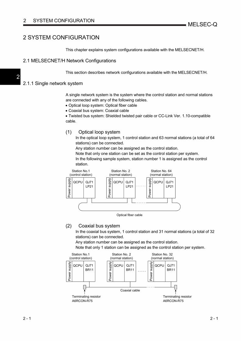
2.1.1 Single network system
A single network system is the system where the control station and normal stations are connected with any of the following cables. Optical loop system: Optical fiber cable Coaxial bus system: Coaxial cable Twisted bus system: Shielded twisted pair cable or CC-Link Ver. 1.10-compatible cable.
(1) Optical loop system
In the optical loop system, 1 control station and 63 normal stations (a total of 64 stations) can be connected. Any station number can be assigned as the control station. Note that only one station can be set as the control station per system. In the following sample system, station number 1 is assigned as the control station.
(2) Coaxial bus system In the coaxial bus system, 1 control station and 31 normal stations (a total of 32 stations) can be connected. Any station number can be assigned as the control station. Note that only 1 station can be assigned as the control station per system.
Optical fiber cable
QCPU
Pow
er s
uppl
y
QJ71LP21
Station No.1 (control station)
QCPU QJ71LP21
QCPU QJ71LP21
Station No. 2 (normal station)
Station No. 64 (normal station)
Pow
er s
uppl
y
Pow
er s
uppl
y
QCPU QCPUQCPU
Terminating resistor A6RCON-R75
Coaxial cable
Terminating resistor A6RCON-R75
QJ71BR11
QJ71BR11
QJ71BR11
Po
wer
sup
ply
Station No.1 (control station)
Station No. 2 (normal station)
Station No. 32 (normal station)
Po
wer
sup
ply
Po
wer
sup
ply
2

2 - 2 2 - 2
MELSEC-Q 2 SYSTEM CONFIGURATION
(3) Twisted bus system
In the twisted bus system, 1 control station and 31 normal stations (a total of 32
stations) can be connected.
Any station number can be assigned as the control station.
Note that, only 1 station can be assigned as the control station per system.
POINT
A safety CPU operates as a normal station. (It cannot be set to a control station.)
QCPU
Station No.1(control station)
Station No.2(normal station)
Station No.32(normal station)
QCPUQJ71NT11B
QJ71NT11B
QJ71NT11B
QCPU
Pow
er s
uppl
y
Pow
er s
uppl
y
Pow
er
supp
ly
Twisted pair cable or CC-Link Ver.1.10-compatible cable
Terminatingresistor
Terminatingresistor
2

2 - 3 2 - 3
MELSEC-Q 2 SYSTEM CONFIGURATION
2.1.2 Redundant system (Redundant CPU)
The redundant system refers to a system where a system including a network module
is dualized by connecting another network module to another redundant CPU
(redundant system).
If failure of the control system CPU or a network module occurs, the redundant system
switches the control system to the standby system, allowing system control and data
linking to be continued on the standby system.
For details, refer to Section 7.10.1.
POINT
The QJ71NT11B does not support the Redundant CPU.
MELSECNET/H PLC to PLC network
Control system Standby system
MELSECNET/H remote I/O network
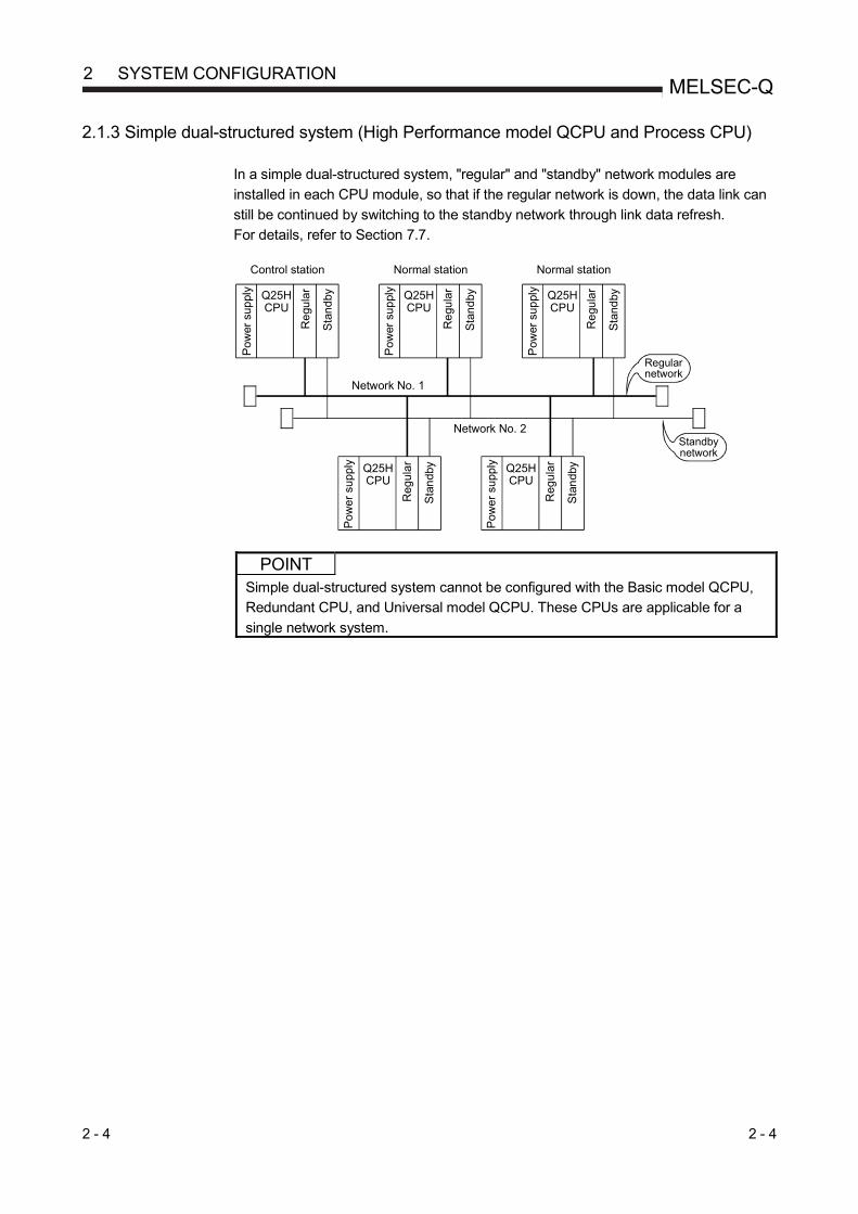
2 - 4 2 - 4
MELSEC-Q 2 SYSTEM CONFIGURATION
2.1.3 Simple dual-structured system (High Performance model QCPU and Process CPU)
In a simple dual-structured system, "regular" and "standby" network modules are
installed in each CPU module, so that if the regular network is down, the data link can
still be continued by switching to the standby network through link data refresh.
For details, refer to Section 7.7.
POINT
Simple dual-structured system cannot be configured with the Basic model QCPU,
Redundant CPU, and Universal model QCPU. These CPUs are applicable for a
single network system.
Network No. 2
Network No. 1
Control station Normal station Normal station
Pow
er s
uppl
y
Standby network
Re
gula
r
Sta
ndby
Pow
er s
uppl
y
Re
gula
r
Sta
ndby
Pow
er s
uppl
y
Re
gula
r
Sta
ndby
Pow
er s
uppl
y
Reg
ular
Sta
ndb
y
Pow
er s
uppl
y
Reg
ular
Sta
ndb
y
Regular network
Q25HCPU
Q25HCPU
Q25HCPU
Q25HCPU
Q25HCPU

2 - 5 2 - 5
MELSEC-Q 2 SYSTEM CONFIGURATION
2.1.4 Multiple network system (High Performance model QCPU, Process CPU, Redundant CPU, and Universal model QCPU)
(1) What is multiple network system The multiple network system is a network system in which multiple networks are connected via relay stations. (a) Duplicated setting of a network number is not allowed. The network
number can be freely set within a range from 1 to 239 unless the same number is used two or more times in a system.
(b) A maximum of 4 network modules can be installed per programmable controller. Note that there are restrictions on the number of modules that can be installed to each programmable controller, depending on the CPU module model. (Refer to the user's manual for the CPU module used.).
POINT
Only one network module can be mounted to the Basic model QCPU, Q00UJCPU, Q00UCPU, Q01UCPU, and safety CPU. For this reason, these CPUs cannot be used as relay stations when configuring a multiple network system using the MELSECNET/H.
(2) Configuration
The following example shows how three networks can be connected.
1st
mod
ule
Network No. 1
Network No. 2
Network No. 4
Network No. 3
2nd
mod
ule
3rd
mod
ule
4th
mod
ule
Q25HCPU
3NS2Normal station
Normal station2NS3
Control station3MP1
1NS3Normal station
Network No. 1
Normal station1NS2
Network No. 2
Normal station2NS2
Po
wer
sup
ply
Control station1MP1
3NS3Normal station
3NS4Normal station
QJ71LP21
QJ71LP21
QJ71LP21
QJ71LP21
Control station2MP1
QJ71LP21
QJ71BR11
QJ71LP21
QJ71BR11
QJ71BR11
QJ71BR11
Network No. 3
Po
wer
sup
ply
Po
wer
sup
ply
Pow
er s
upp
ly
Pow
er s
upp
ly
Pow
er s
uppl
y
Pow
er s
uppl
y
Pow
er s
uppl
y
Q25HCPU
Q25HCPU
Q25HCPU
Q25HCPU
Q25HCPU
Q25HCPU
Q25HCPU

2 - 6 2 - 6
MELSEC-Q 2 SYSTEM CONFIGURATION
2.2 Applicable Systems
This section describes the applicable systems.
No. of mountable modules is the maximum number of mountable network modules
with CC-Link IE Controller Network.
(1) Applicable modules and base units, and number of mountable
modules (a) When mounted with a CPU module
Refer to the user’s manual for the CPU module used. Observe the following: • Use the network module which satisfies the following conditions for the
Redundant CPU.
• Function version D or later
• Network modules other than the QJ71NT11B • Use the network module which satisfies the following conditions for the
safety CPU.
• Serial number (first five digits) "08102" or later
• Function version D or later
• Network modules other than the QJ71NT11B • A shortage of the power capacity may result depending on the
combination of mounted modules or the number of mounted modules. When mounting modules, consider the power capacity. If the power is insufficient, change the combination of modules.
• Mount modules so that the total number of I/O points does not exceed the point range of the CPU module. Modules can be mounted in any slot within the applicable range.
REMARKS
When mounted with a C Controller module, refer to the user’s manual for the C
Controller module used..
(b) When mounted on a MELSECNET/H remote I/O station The network module cannot be mounted on a MELSECNET/H remote I/O
station.
Mount it with a CPU module on the master station.
(c) When mounted on an RQ extension base unit
Refer to the MELSEC iQ-R Module Configuration Manual.
(2) Support of the multiple CPU system
Before using the network module in a multiple CPU system, refer to the QCPU
User’s Manual (Multiple CPU System).
To configure the MELSECNET/H with a multiple CPU system, use a network
module of function version B or later.
For precautions for the use in a multiple CPU system, refer to Section 2.2.2.

2 - 7 2 - 7
MELSEC-Q 2 SYSTEM CONFIGURATION
(3) Compatible network modules Available network types and systems vary depending on the function version of
the network module. (a) When optical loop system or coaxial bus system is used
MELSECNET/H Extended mode MELSECNET/H mode MELSECNET/10 mode
Basic model QCPU Single CPU system
Function version D or later (Serial number (first five digits)
"06092" or later)
Function version A or later
Multiple CPU system Function version B or later
High Performance model QCPU
Single CPU system Function version A or later
Multiple CPU system Function version B or later
Process CPU Single CPU system Function version A or later
Multiple CPU system Function version B or later
Redundant CPU Redundant system Function version D or later
(Serial number (first five digits) "06092" or later)
Function version D or later
Universal model QCPU Single CPU system Function version D or later
(Serial number (first five digits) "06092" or later)
Function version A or later
Multiple CPU system Function version B or later
Safety CPU Single CPU system Function version D or later
(Serial number (first five digits) "08102" or later)
(b) When twisted bus system is used MELSECNET/H Extended mode MELSECNET/H mode
Basic model QCPU Single CPU system
From the first version
Multiple CPU system
High Performance model QCPU
Single CPU system
Multiple CPU system
Process CPU Single CPU system
Multiple CPU system
Redundant CPU Redundant system Not supported
Universal model QCPU Single CPU system
From the first version Multiple CPU system
Safety CPU Single CPU system Not supported

2 - 8 2 - 8
MELSEC-Q 2 SYSTEM CONFIGURATION
(4) Compatible software packages (when using GX Developer) The systems using network modules and compatible software packages are
shown in the table below. (a) When the optical loop system or coaxial bus system is used
MELSECNET/H Extended mode MELSECNET/H mode MELSECNET/10 mode
Q00J/Q00/Q01CPU Single CPU system
Version 8.20W or later
Version 7 or later
Multiple CPU system Version 8 or later
Q02/Q02H/Q06H/ Q12H/Q25HCPU
Single CPU system Version 4 or later
Multiple CPU system Version 6 or later
Q02PH/Q06PHCPU Single CPU system
Version 8.68W or later Multiple CPU system
Q12PH/Q25PHCPU Single CPU system
Version 8.20W or later Version 7.10L or later Multiple CPU system
Q12PRH/Q25PRHCPU Redundant system Version 8.29F or later Version 8.18U or later
Q02U/Q03UD/Q04UDH/ Q06UDHCPU
Single CPU system Version 8.48A or later
Multiple CPU system
Q13UDH/ Q26UDHCPU Single CPU system
Version 8.62Q or later Multiple CPU system
Q03UDE/Q04UDEH/ Q06UDEH/Q13UDEH/ Q26UDEHCPU
Single CPU system Version 8.68W or later
Multiple CPU system
Q00UJ/Q00U/Q01U/ Q10UDH/Q20UDH/ Q10UDEH/Q20UDEHCPU
Single CPU system Version 8.78G or later
Multiple CPU system
QS001CPU Single CPU system Version 8.40S or later
CPU modules other than the above
Single CPU system Not supported
Multiple CPU system
(b) When the twisted bus system is used MELSECNET/H Extended mode MELSECNET/H mode
Q00J/Q00/Q01CPU Single CPU system
Version 8.78G or later
Multiple CPU system
Q02/Q02H/Q06H/ Q12H/Q25HCPU
Single CPU system
Multiple CPU system
Q02PH/Q06PH/ Q12PH/Q25PHCPU
Single CPU system
Multiple CPU system
Q00UJ/Q00U/Q01U/Q02U/ Q03UD/Q04UDH/Q06UDH/ Q10UDH/Q13UDH/Q20UDH/ Q26UDH/Q03UDE/ Q04UDEH/Q06UDEH/ Q10UDEH/Q13UDEH/ Q20UDEH/Q26UDEHCPU
Single CPU system
Version 8.78G or later
Multiple CPU system
CPU modules other than the above
Single CPU system Not supported
Multiple CPU system
(5) Compatible software packages (when using GX Works2)
For a system with a network module and GX Works2 version, refer to the
following manual.
• GX Works2 Version 1 Operating Manual (Common)

2 - 9 2 - 9
MELSEC-Q 2 SYSTEM CONFIGURATION
2.2.1 Precautions when using link dedicated instructions
When accessing to other stations from MELSECNET/H network modules (who issue the request) with function version B or later upon link dedicated instructions, the handling methods are different depending on the module of the target station. The handling methods for each module of the target station are explained below. (1) Link dedicated instructions modified for function version B
The data length of the SEND, READ, SREAD, WRITE and SWRITE instructions is changed (480 words 960 words.) (a) When the target station is a network module
Request issued by
Target station
CC-Link IE Controller Network module
CC-Link IE Field Network
module
MESLECNET/H network module MESLECNET/10 network module Function version B or D Function version A
480 words or less
481 to 960 words 1
: Processed normally : Ends abnormally. Error code returned to the request source. 1: The SEND instruction ends abnormally. Error code returned to the
request source. The READ, SREAD, WRITE, and SWRITE instructions are processed normally.
(b) When the target station is a Q series Ethernet module
Request issued by
Target station (Q series Ethernet module)
Function version D Function version B
Function version A 07082 or later
3 07081 or earlier
3
480 words or less
481 to 960 words 1 1 2
: Processed normally : Ends abnormally. Error code returned to the request source. 1: The SEND instruction ends abnormally. Error code returned to the
request source. The READ, SREAD, WRITE, and SWRITE instructions are processed normally.
2: The operations for the SEND instruction are not normal. (Error support available F7C3H) The READ, SREAD, WRITE, and SWRITE instructions are processed normally.
3: Serial number (first five digits)

2 - 10 2 - 10
MELSEC-Q 2 SYSTEM CONFIGURATION
(2) Instructions added for function version B
Request issued by
Target station
CC-Link IE Controller Network module
CC-Link IE Field Network
module
MELSECNET/H network
module
MELSECNET/10 network
module
Q series Ethernet module
RRUN, RSTOP, RTMRD, RTMWR
: Processed normally. : Ends abnormally. Error code returned to the request source.

2 - 11 2 - 11
MELSEC-Q 2 SYSTEM CONFIGURATION
2.2.2 Precautions when using network modules in the multiple CPU system
Pay attention to the following points when configuring a MELSECNET/H network
system with a multiple CPU system.
(1) Set the network parameters in the control CPU that controls the network
modules.
(2) A maximum of four network modules can be set for each control CPU module.
Note that a total of four network modules can be mounted in the multiple CPU
system.
(a) CPU No.1 controls all network modules. (b) CPU No.1 and CPU No.2 control network modules
separately.
(c) CPU No.1 to CPU No.4 control each network module. (d) Up to 4 network modules can be mounted on the system.
CPU No.1
CPUNo.2
QJ71BR11
QJ71BR11
QJ71BR11
QJ71BR11
CPU No.1
CPUNo.2
QJ71BR11
QJ71BR11
QJ71BR11
QJ71BR11
CPUNo.1
CPUNo.2
QJ71BR11
QJ71BR11
QJ71BR11
QJ71BR11
CPUNo.3
CPUNo.4
CPUNo.1
CPUNo.2
QJ71BR11
QJ71BR11
QJ71BR11
QJ71BR11
QJ71BR11
: The number of modules exceeded the limit.
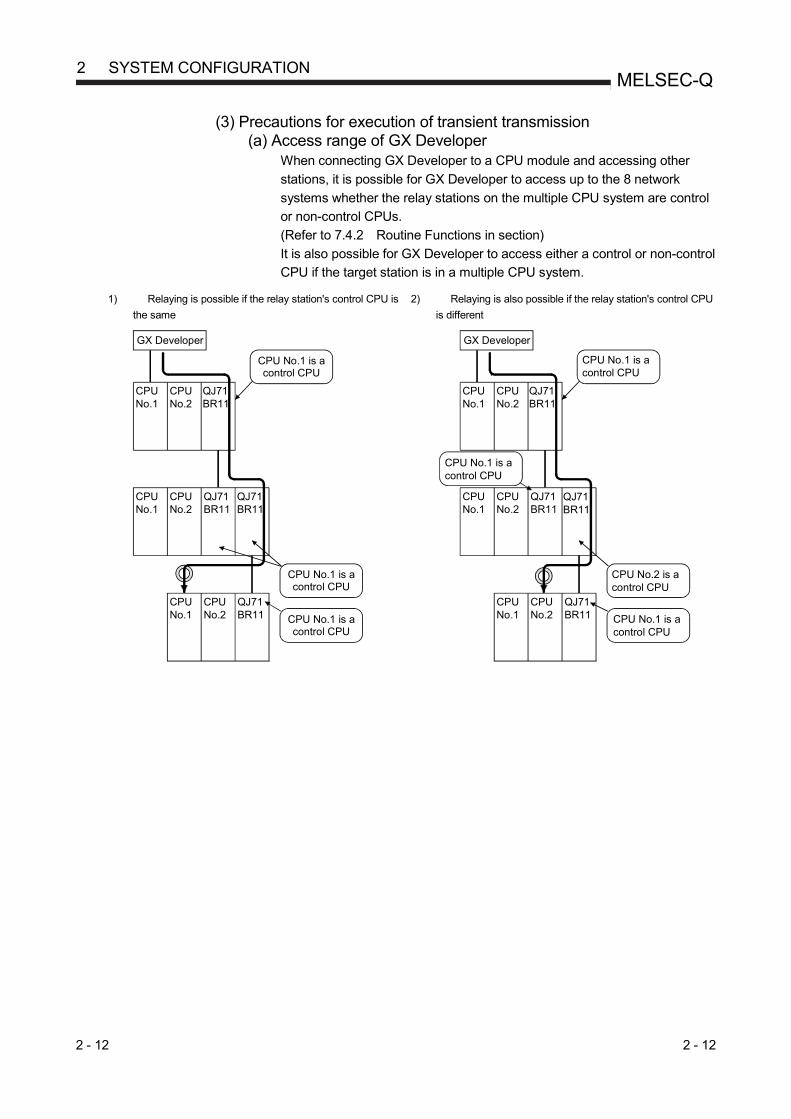
2 - 12 2 - 12
MELSEC-Q 2 SYSTEM CONFIGURATION
(3) Precautions for execution of transient transmission (a) Access range of GX Developer
When connecting GX Developer to a CPU module and accessing other
stations, it is possible for GX Developer to access up to the 8 network
systems whether the relay stations on the multiple CPU system are control
or non-control CPUs.
(Refer to 7.4.2 Routine Functions in section)
It is also possible for GX Developer to access either a control or non-control
CPU if the target station is in a multiple CPU system.
1) Relaying is possible if the relay station's control CPU is
the same
2) Relaying is also possible if the relay station's control CPU
is different
CPUNo.1
CPUNo.2
QJ71BR11
GX Developer
CPUNo.1
CPUNo.2
QJ71BR11
QJ71BR11
CPU No.1
CPU No.2
QJ71BR11
CPU No.1 is a control CPU
CPU No.1 is a control CPU
CPU No.1 is a control CPU
CPU No.1
CPUNo.2
QJ71BR11
GX Developer
CPU No.1
CPU No.2
QJ71BR11
QJ71BR11
CPU No.1
CPU No.2
QJ71BR11
CPU No.1 is a control CPU
CPU No.2 is a control CPU
CPU No.1 is a control CPU
CPU No.1 is a control CPU

2 - 13 2 - 13
MELSEC-Q 2 SYSTEM CONFIGURATION
(b) Setting routing parameters If different control CPUs are set to relay stations, set the same routing
parameter to each of the control CPUs.
The following illustration shows a setting example where transient data are
transmitted from 1Mp1 to 3Ns2.
QCPU(Requestsource)
1Mp1
1Ns3 2Mp1QCPU QCPU
Network No.1
Network No.2
Network No.3
QCPU 1Ns2
QCPU 2Ns3
QCPU 3Ns2
QCPU 2Ns2 3Mp1
1) When different control CPUs are set to relay stations, set the same routing parameter.
When the same control CPU is set to relay stations, set the routing parameter only to the control CPU.
1Ns3 2Mp1QCPU QCPU
No.2No.1
Control CPU is QCPU No.1
Control CPU is QCPU No.2
1Ns3 2Mp1QCPU QCPU
No.2No.1
Control CPU is QCPU No.2
Control CPU is QCPU No.2
(Request destination)
2)
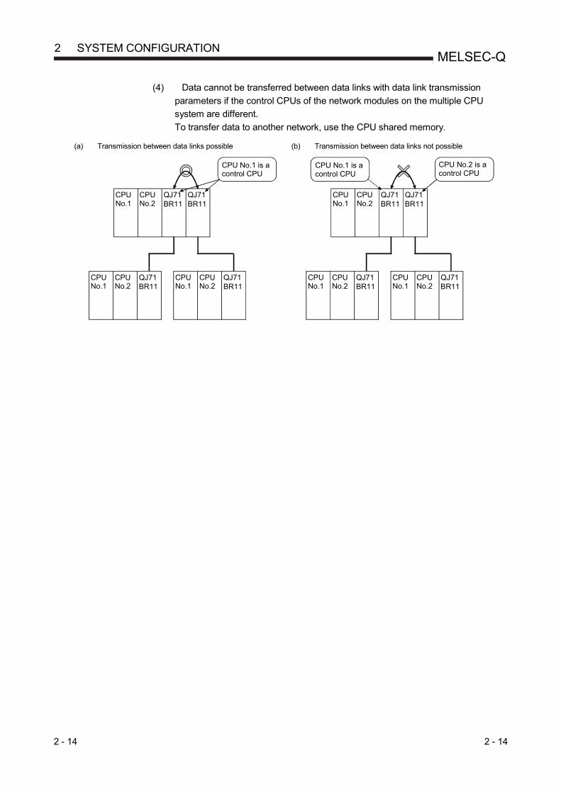
2 - 14 2 - 14
MELSEC-Q 2 SYSTEM CONFIGURATION
(4) Data cannot be transferred between data links with data link transmission
parameters if the control CPUs of the network modules on the multiple CPU
system are different.
To transfer data to another network, use the CPU shared memory.
(a) Transmission between data links possible
(b) Transmission between data links not possible
CPU No.1
QJ71BR11
QJ71BR11
CPUNo.1
CPUNo.2
QJ71BR11
CPU No.1 is a control CPU
CPUNo.1
CPUNo.2
QJ71BR11
CPU No.2
CPUNo.1
QJ71BR11
QJ71BR11
CPUNo.1
CPUNo.2
QJ71BR11
CPU No.2 is a control CPU
CPUNo.1
CPUNo.2
QJ71BR11
CPUNo.2
CPU No.1 is a control CPU

2 - 15 2 - 15
MELSEC-Q 2 SYSTEM CONFIGURATION
(5) Precautions for executing a link dedicated instruction to a multiple CPU system
(Group specification, All stations)
If a WRITE/SWRITE, REQ, RRUN/RSTOP or RTMWR instruction is issued
under the following conditions (a), it may not be executed on some stations
depending on the system configuration (Control CPU setting) of the target
multiple CPU system. (Refer to (b).)
(a) Execution conditions
Item Setting
Target station CPU type ((S1)+3) setting
Set the CPU type to any of the following.
• Multiple CPU system No.1 (03E0H)
• Multiple CPU system No.2 (03E1H)
• Multiple CPU system No.3 (03E2H)
• Multiple CPU system No.4 (03E3H)
Target station No. ((S1)+5) setting
Set the station No. of the target station to either of
the following.
• Group specification (81H to A0H)
• All stations (FFH)
(b) Execution result
Target station
No. ((S1)+5)
setting
Target station CPU type
((S1)+3) setting
Execution result
Target station’s
control CPU is No.1
Target station’s
control CPU is No.2
Target station’s
control CPU is No.3
Target station’s
control CPU is No.4
Group
specification
(81H to A0H) or
All stations
(FFH)
Multiple CPU system
No.1 (03E0H)
Multiple CPU system
No.2 (03E1H)
Multiple CPU system
No.3 (03E2H)
Multiple CPU system
No.4 (03E3H)
O : The instruction is executed.
X : The instruction is not executed. Error completion is not identified on the execution source.

2 - 16 2 - 16
MELSEC-Q 2 SYSTEM CONFIGURATION
(6) When all of the following conditions from a) to d) are met, use a
MELSECNET/H module whose serial number (first five digits) is "10042" or later.
(a) A multiple CPU system containing a Built-in Ethernet port QCPU is
configured.
(b) To the Ethernet port of the Built-in Ethernet port QCPU, GX Developer or
GOT is connected.
(c) From GX Developer or GOT, access is made to another station through a
MELSECNET/H module controlled by another CPU.
(d) The access target on another station is an A/QnA series CPU module.

2 - 17 2 - 17
MELSEC-Q 2 SYSTEM CONFIGURATION
2.2.3 List of functions for each CPU module
The available functions of the MELSECNET/H depend on the CPU module with which a network module is mounted.
1)High Performance model QCPU, Process CPU
2)Basic model QCPU
3)Redundant CPU
4)Universal model QCPU
5)Safety CPU
Function CPU module Reference
section 1) 2) 3) 4) 5)
Cyclic transmission function Section 3.2.1 MELSECNET/H Extended mode Section 5.1
Refresh parameter *1 *1 Section 5.7 Common parameter *2 *2 Section 5.3 Station inherent parameter Section 5.6 Inter-link data transfer function *5*8 Section 7.2 Designation of I/O master station Section 5.3.3 Designation of reserved station Section 5.3.4 Low-speed cyclic transmission function *5*8 Section 7.3 Redundant system function Section 7.10
Transient transmission function Section 7.4 Routing function *1 *1 Section 7.4.2
Group function Section 7.4.3 Message sending function using logical channel numbers Section 7.4.4 Link dedicated instruction *3 *3*6 Section 7.4.5
RAS function Section 3.2.2 Automatic return function Section 3.2.2
Control station shift function Section 3.2.2 Control station return control function Section 3.2.2 Loopback function Section 3.2.2 Station detach function Section 3.2.2 Transient transmission possible even in case of CPU error Section 3.2.2 Confirmation of transient transmission error detection time Section 3.2.2 Module diagnosis Section 3.2.2 Network test *7 *5 *7 Section 7.8 Network diagnosis Section 8.1
Direct accessing of link device Section 7.1 Clock setting to a station on the network by GX Developer Section 7.4.6 Getting the interrupt sequence program started *4 Section 7.5 Multiplexed transmission function Section 7.6 Simplified redundant setting of network Section 7.7 Increasing the number of send points by connecting multiple modules of the same network number Section 7.9
: Available, : Unavailable *1: Up to 8 modules can be set. *2: The low-speed LB/LW cannot be set because these models do not support the low-speed cyclic transmission function. *3: The SREAD/SWRITE instruction’s read/write notice device (D3) becomes invalid. (The same operation as the
READ/WRITE instructions takes place.) *4: It is available for the Basic model QCPU of function version B or later. *5: Available for the Universal model QCPU whose serial No. (first 5 digits) is "09042" or later. *6: For link dedicated instructions for the safety CPU, refer to Section 6.3. *7: Basic model QCPU and safety CPU cannot execute a network test on a sequence program. *8: Applicable to the Universal model QCPU excluding the Q00UJCPU, Q00UCPU, and Q01UCPU.

2 - 18 2 - 18
MELSEC-Q 2 SYSTEM CONFIGURATION
2.3 Checking Serial Number and Function Version
The serial number and function version of the network module can be checked on the
rating plate, front of the module, or system monitor window in GX Developer.
(1) Checking on the rating plate
The rating plate is located on the side of the network module.
(2) Checking on the front of the module The serial number and function version on the rating plate is printed on the front
(at the bottom) of the module.
The following network module is not included.
• QJ71LP21
Serial No.
110620000000000-D Function version

2 - 19 2 - 19
MELSEC-Q 2 SYSTEM CONFIGURATION
(3) Checking on the System Monitor screen (Product Information List) To display the system monitor, select [Diagnostics] [System monitor] Product Inf. List button of GX Developer.
(a) Production number display Since the network module does not support the production number display,
"-" is displayed.
POINT
The serial number displayed on the Product Information List screen of GX
Developer may differ from that on the rating plate or on the front of the module.
• The serial number on the rating plate or on the front of the module indicates
the management information of the product.
• The serial number displayed on the Product Information List screen indicates
the functional information of the product.
The functional information of the product will be updated when a function is
added.
Serial No.Function version
Product No.

3 - 1 3 - 1
MELSEC-Q 3 SPECIFICATIONS
3 SPECIFICATIONS
This chapter explains the performance specifications and function specifications of the network modules as well as the specifications of the send/receive processing time of the link data. For details of the general specifications, refer to the QCPU User's Manual (Hardware Design, Maintenance and Inspection).
3.1 Performance Specifications
3.1.1 Performance specifications
The following table lists the performance specifications of the network modules.
(1) Performance specifications of the optical loop system Item
Optical loop system QJ71LP21 QJ71LP21-25 QJ71LP21S-25 QJ71LP21G QJ71LP21GE
Maximum number of link points per network
LX/LY 8192 points LB 16384 points (8192 points in the MELSECNET/10 mode) LW 16384 points (8192 points in the MELSECNET/10 mode)
Maximum number of link points per station *1 {(LY + LB) / 8 + (2 LW)} 2000 bytes
• MELSECNET/H mode, MELSECNET/10 mode {(LY + LB) / 8 + (2 LW)} 2000 bytes
• MELSECNET/H Extended mode {(LY + LB) / 8 + (2 LW)} 35840 bytes
Communication speed 10 Mbps 25 Mbps/10 Mbps
(Change with mode setting switch) 10 Mbps
Number of stations per network Up to 64 stations (1 control station, 63 normal stations)
Connection cable Optical fiber cable (obtained by user)*2
Applicable connector Two-core optical connector plug (obtained by user) F06/F08 or equivalent (JIS C5975/5977 compliant)
Overall distance 30km
Distance between stations*2
During 25Mbps
SI optical cables: 200m H-PCF optical cables: 400m
Broad-band H-PCF Optical Cables: 1km QSI optical cables: 1km
During 10Mbps
SI optical cables: 500m H-PCF optical cables: 1km
Broad-band H-PCF optical cables: 1km QSI optical cables: 1km
GI-50/125 optical cables: 2km
GI-62.5/125 optical cables: 2km
Maximum number of networks 239 (total including remote I/O networks) Maximum number of groups 32 (9 in the MELSECNET/10 mode) Transmission path format Duplex loop Communication method Token ring Synchronous method Frame synchronous Encoding method NRZI code (Non Return to Zero Inverted) Transmission format Conforms to HDLC (frame type) Error control system Retries based on CRC (X16
+ X12 + X5 + 1) and timeover
RAS function
• Loopback function upon abnormal detection and cable breakage (optical loop system only) • Diagnostic function of host link line check • Prevention of system down by switching the control station • Abnormal detection using link special relays and link special registers
Transient transmission
• N:N communication (monitor, program upload/download, etc.) • Various send/receive instructions from sequence programs (ZNRD/ZNWR, SEND/RECV, RECVS,
READ/WRITE, SREAD/SWRITE, REQ, RRUN/RSTOP, RTMRD/RTMWR.) • Send function addressed to logical channel number of channel numbers 1 to 8
Special cyclic transmission function • Low-speed cyclic transmission function
Number of occupied I/O points 32 points
(I/O assignment: intelli.; 32 points)
48 (I/O assignment: Empty; first 16, intelli.; last 32)*3
32 points (I/O assignment: intelli.; 32 points)
External Power Supply
Voltage 20.4 to 31.2 V DC Current 0.20 A Size of terminal screw M3 Screw Suitable crimp terminal R1.25-3 Suitable cable size 0.3 to 1.25 mm2 Tightening torque 0.42 to 0.58 N·m Allowable momentary power failure time
1ms (Level PS1)
3

3 - 2 3 - 2
MELSEC-Q 3 SPECIFICATIONS
Item Optical loop system
QJ71LP21 QJ71LP21-25 QJ71LP21S-25 QJ71LP21G QJ71LP21GE
External Power Supply
Noise immunity
By noise simulator of 500Vp-p noise voltage, 1s noise width, and 25 to 60Hz noise frequency
Internal current consumption (5VDC) 0.55 A
External dimensions
H 98mm 98mm 98mm W 27.4mm 55.2mm 27.4mm D 90mm 90mm 90mm
Weight 0.11 kg 0.20kg 0.11kg
1 The number of LY points of the stations set in the I/O master station is the sum total of the LY points for output to all stations within the block. 2 For old optical fiber cables (A-2P- ), L type differs from H type in the distance between stations. Refer to Section 4.6.1 for details. 3 Two slots are occupied.
Set the numeric value resulted from adding 10H to the I/O No. of the slot where a module mounted as the "Starting I/O No." of the "Network parameter". The first empty 16 points can be set to "0" on the "I/O assignment" tab screen within the "Q Parameter" screen. Example: Set 10H as the "Starting I/O No." when the module is mounted on slot 0. (Set 0H as the "Starting I/O No." when 0 has been set to slot 0 on the "I/O assignment" tab screen.)
3
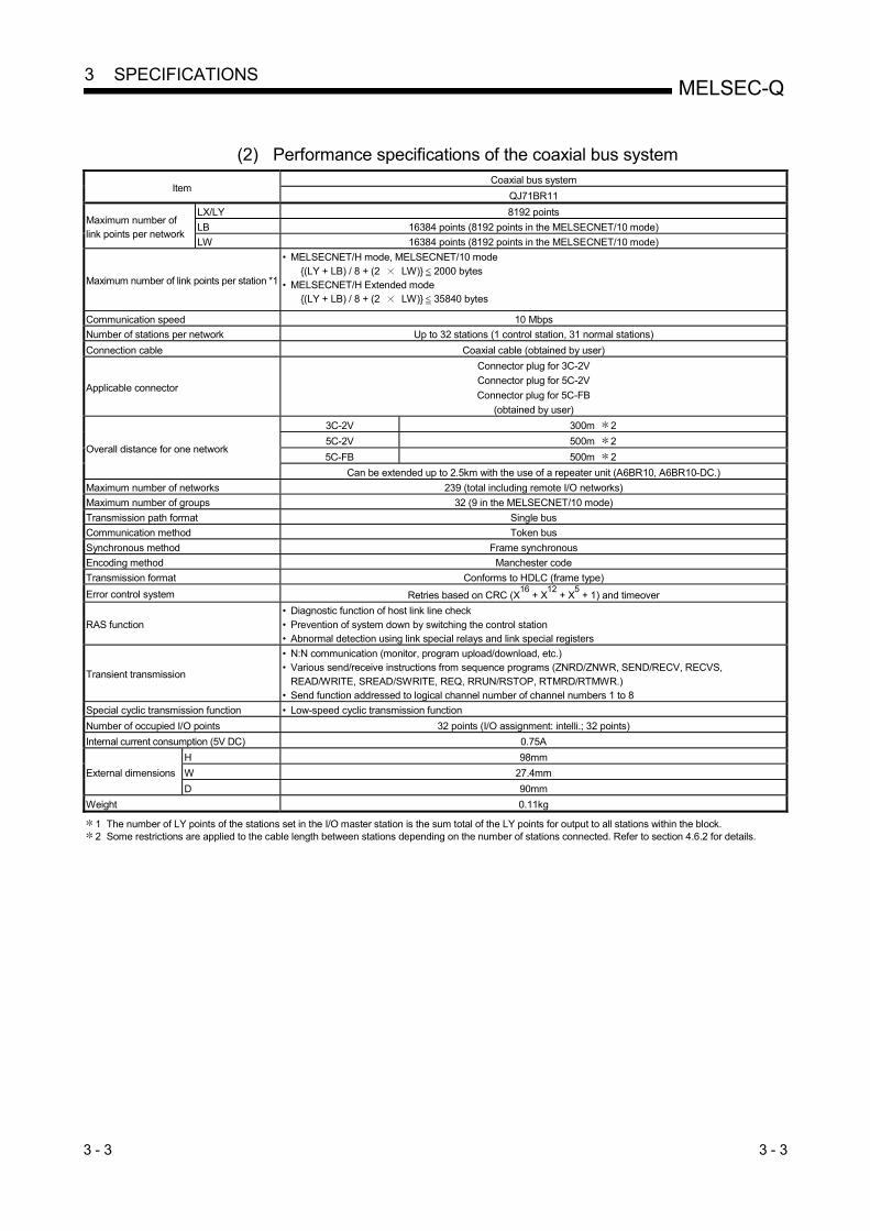
3 - 3 3 - 3
MELSEC-Q 3 SPECIFICATIONS
(2) Performance specifications of the coaxial bus system
Item Coaxial bus system
QJ71BR11
Maximum number of link points per network
LX/LY 8192 points
LB 16384 points (8192 points in the MELSECNET/10 mode)
LW 16384 points (8192 points in the MELSECNET/10 mode)
Maximum number of link points per station *1
• MELSECNET/H mode, MELSECNET/10 mode {(LY + LB) / 8 + (2 LW)} 2000 bytes
• MELSECNET/H Extended mode {(LY + LB) / 8 + (2 LW)} 35840 bytes
Communication speed 10 Mbps
Number of stations per network Up to 32 stations (1 control station, 31 normal stations)
Connection cable Coaxial cable (obtained by user)
Applicable connector
Connector plug for 3C-2V
Connector plug for 5C-2V
Connector plug for 5C-FB
(obtained by user)
Overall distance for one network
3C-2V 300m 2
5C-2V 500m 2
5C-FB 500m 2
Can be extended up to 2.5km with the use of a repeater unit (A6BR10, A6BR10-DC.)
Maximum number of networks 239 (total including remote I/O networks)
Maximum number of groups 32 (9 in the MELSECNET/10 mode)
Transmission path format Single bus
Communication method Token bus
Synchronous method Frame synchronous
Encoding method Manchester code
Transmission format Conforms to HDLC (frame type)
Error control system Retries based on CRC (X16
+ X12
+ X5 + 1) and timeover
RAS function • Diagnostic function of host link line check • Prevention of system down by switching the control station • Abnormal detection using link special relays and link special registers
Transient transmission
• N:N communication (monitor, program upload/download, etc.) • Various send/receive instructions from sequence programs (ZNRD/ZNWR, SEND/RECV, RECVS,
READ/WRITE, SREAD/SWRITE, REQ, RRUN/RSTOP, RTMRD/RTMWR.) • Send function addressed to logical channel number of channel numbers 1 to 8
Special cyclic transmission function • Low-speed cyclic transmission function
Number of occupied I/O points 32 points (I/O assignment: intelli.; 32 points)
Internal current consumption (5V DC) 0.75A
External dimensions
H 98mm
W 27.4mm
D 90mm
Weight 0.11kg
1 The number of LY points of the stations set in the I/O master station is the sum total of the LY points for output to all stations within the block. 2 Some restrictions are applied to the cable length between stations depending on the number of stations connected. Refer to section 4.6.2 for details.

3 - 4 3 - 4
MELSEC-Q 3 SPECIFICATIONS
(3) Performance specifications of the twisted bus system
Item Twisted bus system
QJ71NT11B
Maximum number of
link points per network
LX/LY 8192 points
LB 16384 points
LW 16384 points
Maximum number of link points per station
1
• MELSECNET/H mode
{(LY + LB) / 8 + (2 LW)} 2000 bytes
• MELSECNET/H Extended mode
{(LY + LB) / 8 + (2 LW)} 35840 bytes
Communication speed 156kbps/312kbps/625kbps/1.25Mbps/2.5Mbps/5Mbps/10Mbps (Switched by network parameters)
Number of stations per network Up to 32 stations (1 control station, 31 normal stations)
Connection cable Shielded twisted pair cable or CC-Link Ver.1.10-compatible cable
Overall distance for one network
Communication
speed Shielded twisted pair cable CC-Link Ver.1.10-compatible cable
156kbps 2 1200m 1200m
312kbps 600m 900m
625kbps 400m 600m
1.25Mbps 200m 400m
2.5Mbps
(Not applicable)
200m
5Mbps 150m
10Mbps 100m
Maximum number of networks 239
Maximum number of groups 32
Transmission path format Bus (RS-485)
Communication method Token bus
Synchronous method Frame synchronous
Encoding method Manchester code
Transmission format Conforms to HDLC (frame type)
Error control system Retries based on CRC (X16 + X12 + X5 + 1) and timeover
RAS function
• Diagnostic function of host link line check
• Prevention of system down by switching the control station
• Abnormal detection using link special relays and link special registers
Transient transmission
• N:N communication (monitor, program upload/download, etc.)
• Various send/receive instructions from sequence programs (ZNRD/ZNWR, SEND/RECV, RECVS,
READ/WRITE, SREAD/SWRITE, REQ, RRUN/RSTOP, RTMRD/RTMWR.)
• Send function addressed to logical channel number of channel numbers 1 to 8
Special cyclic transmission function • Low-speed cyclic transmission function
Number of occupied I/O points 32 points (I/O assignment: intelli.; 32 points)
Internal current consumption (5V DC) 0.6A
External dimensions
H 98mm
W 27.4mm
D 90mm
Weight 0.13kg
1 The number of LY points of the stations set in the I/O master station is the sum total of the LY points for output to all stations within the block.
2 This value is set as default of the communication speed.

3 - 5 3 - 5
MELSEC-Q 3 SPECIFICATIONS
3.1.2 Optical fiber cable specifications
This section explains the specifications of the optical fiber cables used with the
MELSECNET/H optical loop system.
Details of the cable specifications must be checked for each cable used.
A technical skill and a special tool are needed when connecting an optical fiber cable
to an exclusive connector.
Optical fiber cables with connectors are available from Mitsubishi Electric System &
Service Co. Ltd. (Catalogs of the optical fiber cables are also available.)
For cabling, consult your local Mitsubishi Electric System & Service representative.
Item
SI (Multi-
particulate
glass)
H-PCF
(Plastic-clad)
Broad-band H-
PCF (Plastic-clad) QSI (Quartz glass)
GI-50/125
(Quartz glass)
GI-62.5/125
(Quartz glass)
Distance
between
stations
10 Mbps 500m 1 km 1 km 1 km 2 km 2 km
25 Mbps 200m 400m 1 km 1 km Must not be used Must not be used
Transmission loss 12 dB/km 6 dB/km 5 dB/km 5.5 dB/km 3 dB/km 3 dB/km
Core diameter 200 m 200 m 200 m 185 m 50 m 62.5 m
Clad diameter 220 m 250 m 250 m 230 m 125 m 125 m
Primary membrane 250 m 250 m Applicable connector F06/F08 or equivalent (JIS C5975/5977 compliant)
REMARKS
The following types of optical fiber cables are available. A type : Cable for connection inside control panel B type : Cable for connection between control panels inside a building C type : Cable for outdoor connection DL type : Reinforced cable for outdoor connection
For other special-purpose cables such as flexible cables or heat-resistant cables, contact Mitsubishi Electric System & Service Co., Ltd.
(1) Cable loss of GI-62.5/125 optical fiber cable
Opticalmodule
IN
OUT
SDRD
SDRD
QJ71LP21GEConversion cable (1m) *1
Adaptor
Connection loss: 1 dB (max.) Connection loss: 1 dB (max.)
AdaptorConversion cable (1m)
SDRD
SDRD
IN
OUT
Total cable loss = 7.5 dB or less
5.5 dB or less
1: Conversion cable
Conversion Type Cable
CA type FC type AGE-1P-CA/FC1.5M-A CA type ST type AGE-1P-CA/ST1.5M-A CA type SMA type AGE-1P-CA/SMA1.5M-A
Purchased from: Mitsubishi Electric Europe GmbH

3 - 6 3 - 6
MELSEC-Q 3 SPECIFICATIONS
3.1.3 Coaxial cable specifications
The following table lists the specifications of the coaxial cables used for the coaxial bus
system.
Use the following high frequency coaxial cables:
• 3C-2V (JIS C 3501 compliant)
• 5C-2V (JIS C 3501 compliant)
• 5C-FB (JIS C 3502 compliant)
(1) Coaxial cable specifications
The following table indicates the specifications of the coaxial cable.
Select coaxial cables that meet the operating ambient temperature (0 to 55 C)
shown in the general specifications of the programmable controller.
Item 3C-2V 5C-2V 5C-FB
Structure Internal conductive material
Insulating material External
conductor Outer sheath
Cable diameter 5.4 mm (0.21 inches) 7.4 mm (0.29 inches) 7.7 mm (0.3 inches)
Minimum allowable bend radius 23 mm (0.91 inches) or more 30 mm (1.18 inches) or more 30 mm (1.18 inches) or more
Internal conductor diameter 0.5 mm (0.02 inches) (annealed
copper wire)
0.8 mm (0.03 inches) (annealed
copper wire)
1.05 mm (0.04 inches) (annealed
copper wire)
Insulating material diameter 3.1 mm (0.12 inches)
(polyethylene)
4.9 mm (0.19 inches)
(polyethylene)
5.0 mm (0.19 inches)
(polyethylene)
External conductor diameter
3.8 mm (0.15 inches)
(single annealed copper wire
mesh)
5.6 mm (0.22 inches)
(single annealed copper wire
mesh)
5.7 mm (0.22 inches)
(aluminum foil tape and annealed
copper wire mesh)
Applicable connector plug
3C-2V connector plug The following connector plugs are recommended: • BNC-P-3-NiCAu*1
(Manufactured by DDK Ltd.) • BCP-C3B*2
(Manufactured by Canare Electric Co., Ltd.)
5C-2V connector plug The following connector plugs are recommended: • BNC-P-5-NiCAu*1
(Manufactured by DDK Ltd.) • BCP-C5B*2
(Manufactured by Canare Electric Co., Ltd.)
5C-FB connector plug BCP-C5FA*2 (manufactured by Canare Electric Co., Ltd.) is recommended.
1: This connector plug is a soldering-type connector plug.
2: This connector plug is a crimping-type connector plug.
REMARKS
To order or for inquiries regarding connector plugs and coaxial cables, contact your local Mitsubishi representative.

3 - 7 3 - 7
MELSEC-Q 3 SPECIFICATIONS
(2) Connecting the coaxial cable connectors
The following section explains how to connect the BNC connector (the connector
plug for the coaxial cable) to the cable.
(a) Using a BNC connector manufactured by DDK Ltd.
The following explains how to connect the BNC-P-3-NiCAu or BNC-P-5-NiCAu to the cable.
CAUTION Correctly solder coaxial cable connectors. Incorrect soldering may result in
malfunction.
Structure of the BNC connector and coaxial cable
Nut Washer Gasket
Clamp Contact
Plug shell
Components of the BNC connector
How to connect the BNC connector and the coaxial cable 1) Cut the portion of the outer sheath of the coaxial cable as shown in the
figure below.
A
Cut this portion of the outer sheath
Cable A
3C-2V 15mm (0.59 inches)
5C-2V, 5C-2V-CCY 10mm (0.39 inches)
2) Fit the nut, washer, gasket, and clamp onto the coaxial cable, as
shown below, and then loosen the external conductor. Clamp
Gasket
WasherNut
3) Cut the external conductor, insulating material and internal conductor
to the dimensions shown below. Note that the external conductor must be cut to the same dimension as the tapered section of the clamp and
smoothed down to the clamp.
B
C
Clamp and external conductor
Insulating materialInternal conductor
Cable B C
3C-2V 6mm
(0.24 inches)
3mm
(0.12 inches)
5C-2V, 5C-2V-CCY 7mm
(0.28 inches)
5mm
(0.20 inches)

3 - 8 3 - 8
MELSEC-Q 3 SPECIFICATIONS
4) Solder the contact to the internal conductor.
Solder here
5) Insert the connector assembly shown in (4) into the plug shell and
screw the nut into the plug shell.
POINT
(1) Note the following precautions when soldering the internal conductor and
contact.
• Make sure that the solder does not bead up at the soldered section. • Make sure there are no gaps between the connector and cable insulator or
they do not cut into each other.
• Perform soldering quickly so the insulation material does not become deformed.
(2) Before connecting or disconnecting the coaxial connector, touch a grounded
metal object to discharge the static electricity from the human body. Failure to do so may result in a module malfunction.

3 - 9 3 - 9
MELSEC-Q 3 SPECIFICATIONS
(b) Using a BNC connector manufactured by Canare Electric Co., Ltd.
The following explains how to connect the BCP-C3B, BCP-C5B, or BCP-
C5FA to the cable. Structure of the BNC connector and coaxial cable
How to connect the BNC connector and the coaxial cable
1) Thread a coaxial cable through a crimping sleeve as shown in the
figure below. When using a cable with aluminum tape, cut the tape as shown in the
figure below.
When cutting the tape, make a clean cut, without leaving any stray
pieces or loose strands. Failure to do so may cause a short circuit or result in an improper crimp.
2) Insert a center contact pin into the internal conductor. Crimp the pin
using a crimp tool to seal the gap between the center contact pin and
the insulating material.
POINT
(1) Use a crimp tool specified for a BNC connector.
(2) Do not crimp the junction of the insulating material and the center contact pin.
(3) Horizontally insert the center contact pin into the insulating material and crimp the pin. If the pin is on the tilt, straight it.

3 - 10 3 - 10
MELSEC-Q 3 SPECIFICATIONS
3) After the crimp, check the crimp height of the crimp part. When the
crimp height at the measurement position is between 1.4mm and
1.5mm, the pin is properly crimped. If the crimp height is not between 1.4mm and 1.5mm, adjust the crimp
tool and crimp the center contact pin again.
4) Hold the root of the coaxial cable and fully insert the cable into a plug.
After inserting the cable, pull it lightly to check that the center contact pin is fixed.
Move the crimp sleeve until it contacts with the plug.
5) Crimp the crimp sleeve using the crimp tool with attention paid to the orientations of the crimp tool and connector.
Do not pull the cable when crimping the sleeve.
POINT
Before connecting or disconnecting the coaxial connector, touch a grounded metal
object to discharge the static electricity from the human body. Failure to do so may
result in a module malfunction.

3 - 11 3 - 11
MELSEC-Q 3 SPECIFICATIONS
3.1.4 Shielded twisted pair cable specifications
The following shows the specifications of a shielded twisted pair cable used in the twisted bus system.
Shielded twisted pair cables that satisfy the following specifications can also be used
even not introduced.
(1) Shielded twisted pair cable specifications The following table lists the shielded twisted pair cable specifications.
Item KNPEV-SB 0.5SQ×1P 1
Cross section
Cable Shielded twisted pair cable
Core 2-core
Conductor resistance (20 C) 39.4 /km or less
Insulation resistance (20 C) 10000M •km or more
Dielectric withstand voltage V-min 1000VAC 1 minute
Capacitance (1KHz) 70nF/km or less on average
Characteristic impedance (100KHz) 110±10
1: Applicable only when the communication speed is 1.25Mbps or less.

3 - 12 3 - 12
MELSEC-Q 3 SPECIFICATIONS
(2) Connection of shielded twisted pair cables and terminals
This section explains connecting method of terminal and cable.
(a) Applicable solderless terminals and crimping tools
Product name Model Manufacturer Remarks
Solderless terminal FA-VTC125T9 For inquiries and orders, please contact
your local Mitsubishi Electric Engineering
Co., Ltd representative.
0.3 to 1.65mm2
Tool dedicated for
solderless terminal FA-NH65A
Solderless terminal TE0.5-10 For inquiries and orders, please contact
your local NICHIFU TERMINAL MFG. Co.,
Ltd representative.
0.3 to 0.5mm2
Tool dedicated for
solderless terminal NH-79
Solderless terminal AI0.5-10WH
For inquiries and orders, please contact
your local Phoenix Contact representative.
0.5mm2
Tool dedicated for
solderless terminal
CRIMPFOX UD6
CRIMPFOX UD6-4 1
CRIMPFOX UD6-6 1
CRIMPFOX ZA3 1: If a shielded or FG wire is crimped to a solderless terminal using the CRIMPFOX UD6-4 or CRIMPFOX
UD6-6, the wire may not be connected to the terminal block depending on the condition of cross section
of the solderless terminal after crimping.
(b) Stripping the cable end
Use an appropriate tool to crimp the solderless terminal. (Refer to (a) in this section)
For details of the crimping method, refer to the manuals for the solderless
terminal or crimping tool used. In the example, a crimping tool "FA-VTC125T9" manufactured by
Mitsubishi is used. 1) Strip the cable jacket by 5.5mm to 6.5mm. 2) Place the terminal in the correct place (in the end) of the locator.
3) Insert the terminal until it reaches to the locator.
4) Insert the stripped cable into the terminal and crimp it.

3 - 13 3 - 13
MELSEC-Q 3 SPECIFICATIONS
3.1.5 CC-Link Ver. 1.10-compatible cable specifications
(1) CC-Link Ver. 1.10-compatible cables for the twisted bus system The following CC-Link Ver. 1.10-compatible cables can be used.
Product name Model Manufacturer
CC-Link Ver. 1.10-
compatible cable
FANC-110SBH Mitsubishi Electric System & Service Co., Ltd.
FA-CBL200PSBH Mitsubishi Electric Engineering Co., Ltd.
(2) Connection of a solderless terminal to the Version 1.10 compatible
CC-Link dedicated cable For connection method of a solderless terminal and the cable, refer to Section
3.1.4 (2).
REMARKS
For details, refer to the CC-Link cable wiring manual issued by CC-Link Partner
Association.

3 - 14 3 - 14
MELSEC-Q 3 SPECIFICATIONS
3.2 Function Specifications
This section describes the functions of the MELSECNET/H. The list of functions is shown below:

3 - 15 3 - 15
MELSEC-Q 3 SPECIFICATIONS
3.2.1 Cyclic transmission function (periodical communication)
The cyclic transmission function periodically allows data communication between stations on the same network using the link devices (LB/LW/LX/LY).
In this manual, the devices on the network module side are prefixed by "L" so that
devices on the CPU module side (B/W/X/Y) and the link devices on the network module side can be distinguished. (1) Communication using LB/LW
By using this function, it is possible to write data to the link relay (LB) and link register (LW) of the network module and to send the data to all the stations
connected within the same network. (a) Available device range
Assign the link devices (LB/LW) in the network within the valid range for writing data of each station on the common parameter LB/LW setting
screen of the control station. In addition, the actual device range may be set
with the refresh parameters or the station inherent parameters for each station.
(b) Data communication
The link relay (LB) can send and receive the on/off information and the link register (LW) can send and receive 16-bit data.
For example, in a network consisting of a control station and two normal
stations, when B0 of the control station turns on, the B0 contacts of the two normal stations turn on. At this point, the station inherent parameters have
not been set. Common parameter
LB/LW settings
B0
B200
B100
Datasendingarea of 1MP1
0
FF100
1FF200
2FF
Control station 1MP1
0
FF100
1FF200
2FF
LB/LW data of 1MP1
LB/LW data of 1NS2
LB/LW data of 1MP1
0
FF100
1FF200
2FF
Normal station 1NS3
B(LB)
B(LB) B(LB)
B100
B200
B0
B100
B0
B200
The LB/LW information of
other stations on the network is
transmitted to each station.
to
to
to
Data receiving area of 1NS2
Data receiving area of 1NS3
Datasendingarea of 1NS2
Data receiving area of 1MP1
Normal station 1NP2
to
to
to
LB/LW data of 1NS2
LB/LW data of 1NS3 LB/LW data of 1NS3
Data receiving area of 1NS3
Data sending area of 1NP3
Data receiving area of 1MP1
Data receiving area of 1NS2
to
to
to

3 - 16 3 - 16
MELSEC-Q 3 SPECIFICATIONS
(2) Communication using LX/LY
This function allows 1:1 communication between the I/O master station that
controls LX/LY and other stations (maximum of 63 stations in the optical loop system and maximum of 31 stations in the coaxial bus system and twisted bus
system).
(a) Available device range
Data communication is performed using the input (X) and output (Y) after the actual I/O of the host.
For the assignments of the link devices (LX/LY) in the network, the I/O
master station and the valid range for writing data for each station are set on the common parameter LX/LY setting screens (two screens) of the
control station. The actually available device ranges can also be set for
each station with refresh parameters. Up to two stations in a network may be set as the I/O master stations.
(b) Data communication
The link input (LX) can send/receive the input information of each station in
the block and the link output (LY) can send/receive the output information of the I/O master station.
For example, in a network consisting of a control station and three normal
stations, the on/off status can be controlled using the input/output devices between each station and the I/O master station in each block, as shown
below.
1NS2
I/O master station 1MP1
1NS3 1NS4
Block 1
LYLY
LYLXLX
LX
1NS2 1NS4
Block 2
Control station 1MP1
Common parameter
LX/LY settings
Block 1 I/O master station
Block 2 I/O master station
LY
LX LY
LX
Normal station 1NS2
Normal station 1NS3
Normal station 1NS4
I/O master station 1NS3
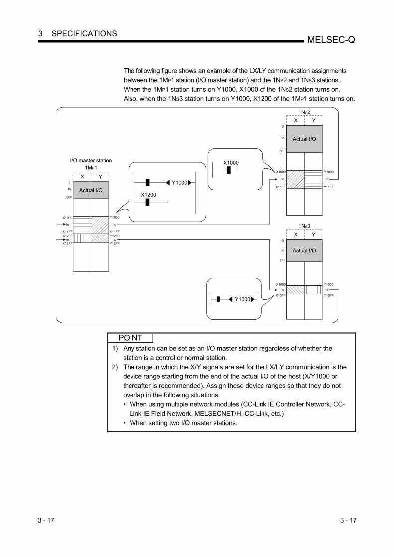
3 - 17 3 - 17
MELSEC-Q 3 SPECIFICATIONS
The following figure shows an example of the LX/LY communication assignments
between the 1MP1 station (I/O master station) and the 1NS2 and 1NS3 stations.
When the 1MP1 station turns on Y1000, X1000 of the 1NS2 station turns on. Also, when the 1NS3 station turns on Y1000, X1200 of the 1MP1 station turns on.
X Y
1NS2
Actual I/O
0
8FF
X1000
X11FF
Y1000
Y11FF
7FF
X1000 Y1000
0
X10FF Y10FF
X Y
1NS3
Actual I/O
X1000
Y1000
X Y
I/O master station1MP1
Actual I/O6FF
X11FFX1200
Y11FFY1200
0
X1000 Y1000
X12FF Y12FF
Y1000
X1200
to to
to to
to
to
toto
to
to to
POINT
1) Any station can be set as an I/O master station regardless of whether the
station is a control or normal station.
2) The range in which the X/Y signals are set for the LX/LY communication is the device range starting from the end of the actual I/O of the host (X/Y1000 or
thereafter is recommended). Assign these device ranges so that they do not
overlap in the following situations: • When using multiple network modules (CC-Link IE Controller Network, CC-
Link IE Field Network, MELSECNET/H, CC-Link, etc.)
• When setting two I/O master stations.
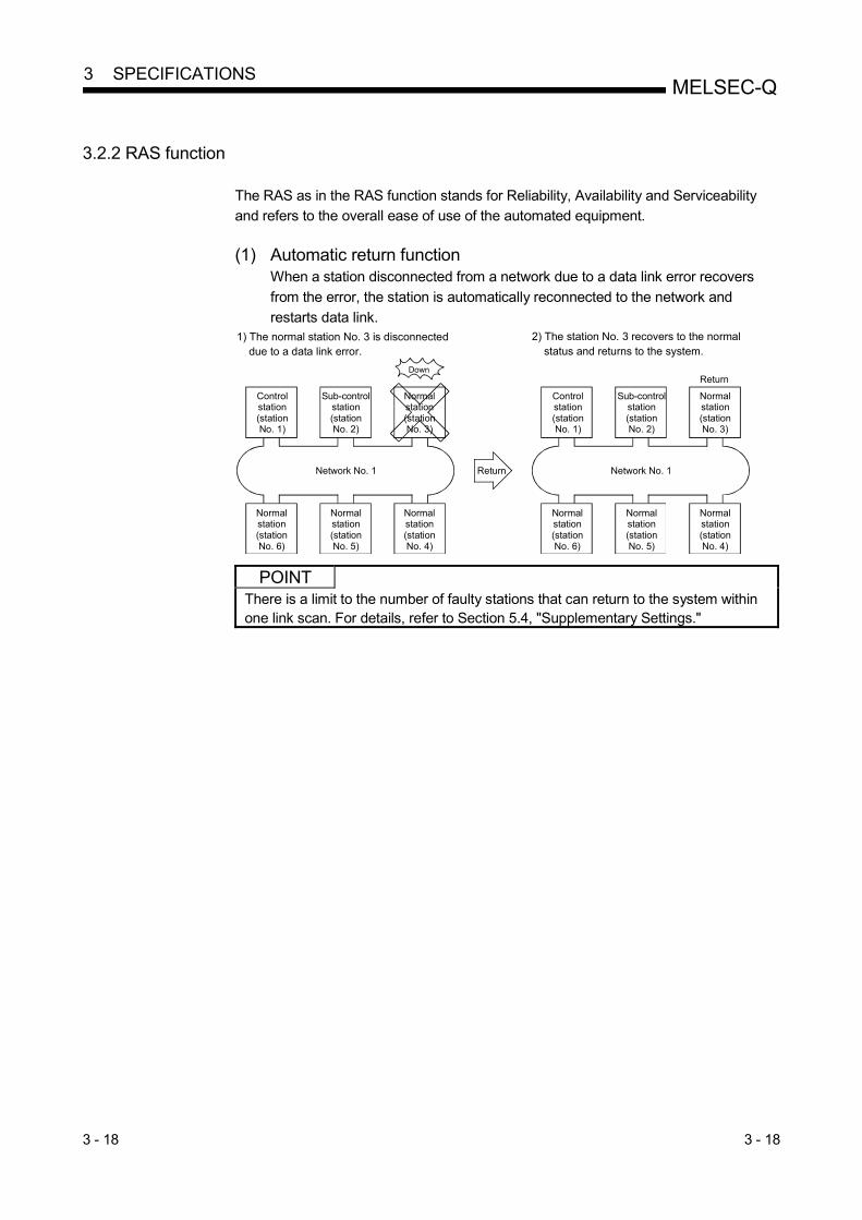
3 - 18 3 - 18
MELSEC-Q 3 SPECIFICATIONS
3.2.2 RAS function
The RAS as in the RAS function stands for Reliability, Availability and Serviceability and refers to the overall ease of use of the automated equipment.
(1) Automatic return function
When a station disconnected from a network due to a data link error recovers
from the error, the station is automatically reconnected to the network and
restarts data link.
Down
Control station (station No. 1)
Network No. 1 Network No. 1Return
1) The normal station No. 3 is disconnected due to a data link error.
2) The station No. 3 recovers to the normal status and returns to the system.
Return
Sub-control station (station No. 2)
Normal station (station No. 3)
Control station (station No. 1)
Sub-control station (station No. 2)
Normal station (station No. 3)
Normal station (station No. 6)
Normal station (station No. 5)
Normal station (station No. 4)
Normal station (station No. 6)
Normal station (station No. 5)
Normal station (station No. 4)
POINT There is a limit to the number of faulty stations that can return to the system within one link scan. For details, refer to Section 5.4, "Supplementary Settings."

3 - 19 3 - 19
MELSEC-Q 3 SPECIFICATIONS
(2) Control station switch function
By using this function, if the control station (the station for which the common
parameters have been set) goes down, another normal station becomes the sub-control station to continue the data link.
Network No. 1 Network No. 1
1) When the control station goes down, the station No. 2 becomes the sub-control station.
2) When the sub-control station No. 2 goes down, the station No. 3 becomes the sub-control station.
Switch Down Switch
Normal station (station No. 6)
Normal station (station No. 5)
Normal station (station No. 4)
Normal station (station No. 6)
Normal station (station No. 5)
Normal station (station No. 4)
Control station (station No. 1)
Sub-control station (station No. 2)
Normal station (station No. 3)
Control station (station No. 1)
Sub-control station (station No. 2)
Sub-control station (station No. 3)
Down
(a) When switching the control station, whether to continue the cyclic transmission or not can be selected from sub-control station. • Common parameter supplementary setting: "Data link by sub-control
station when control station is down." is available. (For more details, refer to Section 5.4, "Supplementary Settings.")
Selection of function Operation during control station switching
Cyclic transmission Transient transmission
1 Select
2 Do not select
: Continued, : Stopped
(b) When the control station is switched, the data link stops temporarily. During
the data link pause, data immediately before the stop is maintained.
(c) During the data link pause, all the stations except the host are treated as faulty stations.
REMARKS
1) The control station does not switch even if the cyclic transmission of the control station is stopped with GX Developer (Refer to Section 7.8).
2) Any of the normal stations whose cyclic transmission is stopped with GX Developer can be a control station.

3 - 20 3 - 20
MELSEC-Q 3 SPECIFICATIONS
(3) Control station return control function
The network stop time can be eliminated by correcting the errors that caused the control station to go down and making it return to the network as a normal station. How the control station returns to the network can be selected by the network settings. For details of the network setting, refer to Section 5.5, "Control Station Return Setting." For the control station return control function in the redundant system, refer to Section 7.10.6.
Selection of function Control station after returning
1 Return as the control station The control station returns as the control station of the network.
2 Return as a normal station
The control station returns to the network again as a normal station, making the operating
sub-control station the new control station of the network. It can become the control station
again only by returning to the network when all other stations have gone down.
Down
Network No. 1 Network No. 1Return
1) When the control station is down, the station No. 2 becomes the sub-control station.
2) The network does not stop since the control station returns to the network as a normal station.
Return
Control station (station No. 1)
Sub-controlstation (station No. 2)
Normal station (station No. 3)
Control station (station No. 1)
Sub-controlstation (station No. 2)
Normal station (station No. 3)
Normal station (station No. 6)
Normal station (station No. 5)
Normal station (station No. 4)
Normal station (station No. 6)
Normal station (station No. 5)
Normal station (station No. 4)
REMARKS
• When "Return as the control station" is selected, the network stop time becomes longer because the baton pass is stopped, but the common parameters can be changed only by resetting the CPU of the control station.
• If "Return as a normal station" is selected, the network does not stop because the control station returns to the network without stopping the baton pass. However, it is necessary to reset the CPUs of all the stations after changing the common parameters of the control station while the network is operating. If only the CPU of the control station is reset, a parameter mismatch error is detected in the control station and it is disconnected from the network.

3 - 21 3 - 21
MELSEC-Q 3 SPECIFICATIONS
(4) Loopback function (optical loop system)
In the optical loop system, the transmission path is dual-structured. When an
error occurs in a transmission path, the faulty area is disconnected by switching the transmission path from the forward loop to the reverse loop or from the
reverse loop to the forward loop, or performing a loopback. The transmission is
continued normally between the stations that are still able to perform data communication.
(a) When normal
The data link is performed using the forward loop (or the reverse loop).
Data flow
Forward loop
Control station(station No. 1)
Reverse loop
Normal station(station No. 6)
Normal station(station No. 5)
Normal station(station No. 3)
Normal station(station No. 4)
Normal station(station No. 2)
(b) When abnormal
1) Error in the forward loop (reverse loop) The data link continues using the reverse loop (forward loop).
Cable disconnection
Control station(station No. 1)
Normal station(station No. 6)
Normal station(station No. 5)
Normal station(station No. 3)
Normal station(station No. 4)
Normal station(station No. 2)
2) When some of the stations are down
The data link continues excluding the stations that are down. When two or more stations are down, the data link cannot be
performed with the station located between the stations that are down.
However, when there are two or more stations between the stations that are down, the normal station with younger station number
becomes the sub-control station to continue the data link.
Sub-control station
Down
DownLoopback Communication
disabled
Loopback
Control station(station No. 1)
Normal station(station No. 6)
Normal station(station No. 5)
Normal station(station No. 3)
Normal station(station No. 4)
Normal station(station No. 2)
Control station(station No. 1)
Normal station(station No. 6)
Normal station(station No. 5)
Normal station(station No. 3)
Normal station(station No. 4)
Normal station(station No. 2)
Down
Down

3 - 22 3 - 22
MELSEC-Q 3 SPECIFICATIONS
(c) Precautions in using the optical loop system
1) When the cable is inserted or removed, the line (forward loop/reverse
loop) may be switched, but the data link will be performed normally.
2) When the loopback is being executed due to a cable disconnection, both the forward and reverse loops may be recognized as normal
depending on the condition of the cable disconnection.
Whether the forward/reverse loop is normal/abnormal is determined by the status of "RD" (receive) of the loopback station.
(Example) In the cases described below, the data link continue by dividing the network into
two loops: "1MP1-1NS5-1NS6" and "1NS2-1NS3-1NS4."
<Loop containing 1MP1-1NS5-1NS6> 1MP1: Forward loop normal/reverse loop normal 1NS5: Forward loop normal/reverse loop normal 1NS6: Forward loop normal/reverse loop normal
<Loop containing 1NS2-1NS3-1NS4> 1NS2: Forward loop "RD" abnormal/reverse loop normal 1NS3: Forward loop normal/reverse loop normal 1NS4: Forward loop normal/reverse loop "RD" abnormal
Forward loopabnormalReverse loopabnormal
Forward loopnormalReverse loopnormal
Loopback
1MP1
Loopback
1NS2 1NS3
1NS6 1NS5 1NS4
Control station
For
war
d R
D
An RD abnormal detection in the forward loop Loopback with the reverse loop
An RD abnormal detection in the reverse loop Loopback with the forward loop
Sub-control station
Normal station Normal station
Re
vers
e S
D
Re
vers
e R
DF
orw
ard
SD
For
war
d R
DR
eve
rse
SD
Re
vers
e R
DF
orw
ard
SD
For
war
d R
DR
eve
rse
SD
Re
vers
e R
DF
orw
ard
SD
For
war
d
SD
Rev
erse
R
D
Rev
erse
S
DF
orw
ard
RD
Loopback Loopback
Normal station Normal station Normal station
For
war
d
SD
Rev
erse
R
D
Rev
erse
S
DF
orw
ard
RD
For
war
d
SD
Rev
erse
R
D
Rev
erse
S
DF
orw
ard
RD
3 - 23 3 - 23
MELSEC-Q 3 SPECIFICATIONS
REMARKS
If the network module has become faulty, a loopback may not be made depending on the fault. In this case, the data link may become deactivated. Identify the faulty network module in the following method. (1) Check the LED indications (RUN LED off, ERR. LED on) of all network modules
for a faulty station. (2) Turn off the power to all stations, then turn it on in order from the control station.
In this process, check to which station of the network loopback is properly executed. Confirm in the Link information of the Network diagnostics (Host information) screen that the control station and the normal station returned to the network is displayed as loopback stations. (Refer to Section 8.1.1.)
Replace any network module in which malfunction has been detected, and confirm that the data link is properly recovered.

3 - 24 3 - 24
MELSEC-Q 3 SPECIFICATIONS
(5) Prevention of station failure by using external power supply (Optical
loop system) Direct power supply (24 V DC) from outside to network modules will prevent the loopback operation. Because of this, station(s) placed between faulty stations will not go down when more than one station go down, (The QJ71LP21S-25 is the network module where power can be supplied from outside.) Even if the distance between normally operating stations (1Ns2 and 1Ns4, 1Ns4 and 1Ns6) is 1 km or more, normal data link will be available
(a) Precautions for operation
If the external power supply of the network module is powered on while the
CPU module power supply is off, the network module will not normally
operate. Power on the CPU module and the external power supply then start system
operations.
REMARKS
Even if the CPU module on the control station is powered off, the control station will not shift to a normal station because the network module operates normally.

3 - 25 3 - 25
MELSEC-Q 3 SPECIFICATIONS
(6) Station detach function (coaxial bus system and twisted bus
system) In the coaxial bus system and twisted bus system, even if the power to a connected station is turned off, the data link continues between other stations
which are still able to perform data communication.
(a) When normal
Terminating resistor
Control station
(station No. 1)
Normal station
(station No. 2)
Normal station
(station No. 3)
Normal station
(station No. 4)
Terminating resistor
(b) When abnormal
The data link continues excluding the station that is down.
Control station
(station No. 1)
Normal station
(station No. 2)
Normal station
(station No. 3)
Normal station
(station No. 4)
Down
POINT
When a cable disconnection occurs, the data link cannot be performed because
there will be no terminating resistors.
Cable disconnection
Control station
(station No. 1)
Normal station
(station No. 2)
Normal station
(station No. 3)
Normal station
(station No. 4)
In addition, even if the cable is normal, the data link cannot be performed if a terminating resistor is detached.

3 - 26 3 - 26
MELSEC-Q 3 SPECIFICATIONS
(7) Transient transmission enabled even at CPU module error
By using this function, the network module can continue the transient transmission even if an error that stops the CPU module occurs while the system is operating. The description of the error of the corresponding station can be checked from other stations using GX Developer.
OPERATION ERROR
GX Developer
QCPU
Po
wer
sup
ply
QJ71
LP21
QCPU
Pow
er s
upp
ly
QJ71
LP21
QCPU
Pow
er s
upp
ly
QJ71
LP21
QCPU
Pow
er s
uppl
y
QJ71
LP21
The following table lists the operations of the cyclic and transient transmissions for each CPU module status.
CPU module status
Cyclic transmission Transient transmission Rank
Battery error
Annunciator error ON, etc.
(Continue error) Minor error Continued Enabled
Parameter error
Instruction code error, etc.
(Stop error) Medium error Stopped Enabled
CPU reset, etc.
(MAIN CPU down) Major error Stopped Disabled 1
1 When the CPU module on the target station is an ACPU, a communication
error occurs. In case of the QCPU and QnACPU, a CC-Link IE Controller Network, CC-Link IE Field Network, MELSECNET/H, MELSECNET/10 error is returned.
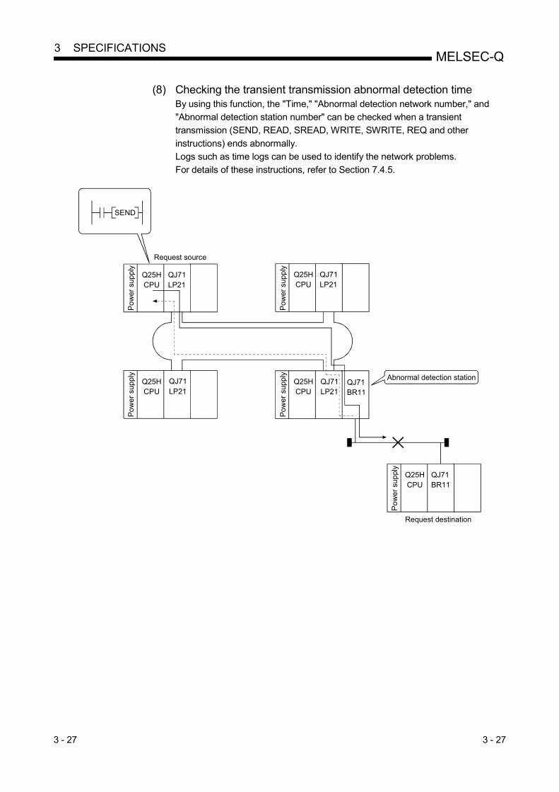
3 - 27 3 - 27
MELSEC-Q 3 SPECIFICATIONS
(8) Checking the transient transmission abnormal detection time
By using this function, the "Time," "Abnormal detection network number," and "Abnormal detection station number" can be checked when a transient
transmission (SEND, READ, SREAD, WRITE, SWRITE, REQ and other
instructions) ends abnormally. Logs such as time logs can be used to identify the network problems.
For details of these instructions, refer to Section 7.4.5.
Request destination
QJ71BR11
Request source
SEND
Abnormal detection station
QJ71LP21
QJ71LP21
QJ71LP21
QJ71LP21
QJ71BR11
Pow
er s
uppl
y
Pow
er s
uppl
y
Pow
er s
uppl
y
Pow
er s
uppl
y
Pow
er s
upp
ly
Q25HCPU
Q25HCPU
Q25HCPU
Q25HCPU
Q25HCPU

3 - 28 3 - 28
MELSEC-Q 3 SPECIFICATIONS
(9) Diagnostic function
The diagnostic function is used to check the network's line status and the module
setting status. The diagnostic function consists mainly of following two types of tests:
• Offline tests
• Online tests
POINT
Execute the online tests when the network module is communicating (T.PASS LED is on). An error occurs if any of the online tests is executed from a station that has
been disconnected from the data link.
1) Offline tests The network module's hardware and the data link cable wiring can be
checked at the system startup by setting the network module or GX
Developer to the test mode.
Item Description Optical loop
system
Coaxial/twisted
bus system
Reference
section
Self-loopback test
Checks hardware including the send/receive circuits and the
cables of the transmission system of an individual network
module.
Section 4.5.1
Internal self-loopback test Checks hardware including the send/receive circuits of the
transmission system of an individual network module. Section 4.5.2
Hardware test Checks hardware inside the network module. Section 4.5.3
Station-to-station test Checks a line between two stations. Section 4.7.1
Forward loop/reverse
loop test
Checks the wiring status of the forward and reverse loops in
the status in which all the stations are connected. Section 4.7.2
2) Online tests The status of a line and other items can be easily checked with GX
Developer.
If an error occurs while the system is in operation, the diagnostics listed below can be executed while remaining in the online status.
Item Description Optical loop
system
Coaxial/twisted
bus system
Data link status
(cyclic transmission or
transient transmission)
Reference
section
Loop test Checks the line status. Pause Section 4.8.1
Setup confirmation test Checks for duplicate control stations and
station numbers. 1 Pause Section 4.8.2
Station order check test
Checks the order of stations connected
in the directions of the forward and
reverse loop.
Pause Section 4.8.3
Communication test
Checks whether or not the transient
transmission can be performed normally.
It also checks the routing parameter
settings.
Continue Section 4.8.4
1: The setup confirmation test cannot be executed in the twisted bus system.
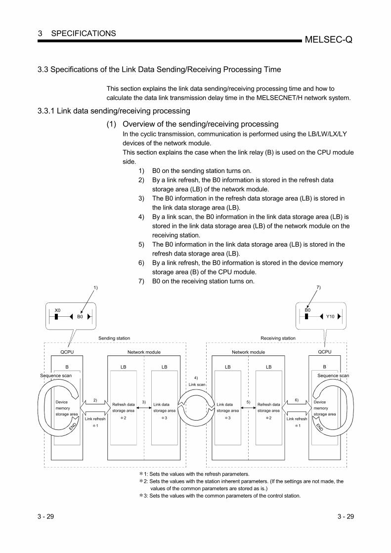
3 - 29 3 - 29
MELSEC-Q 3 SPECIFICATIONS
3.3 Specifications of the Link Data Sending/Receiving Processing Time
This section explains the link data sending/receiving processing time and how to calculate the data link transmission delay time in the MELSECNET/H network system.
3.3.1 Link data sending/receiving processing
(1) Overview of the sending/receiving processing In the cyclic transmission, communication is performed using the LB/LW/LX/LY devices of the network module.
This section explains the case when the link relay (B) is used on the CPU module
side. 1) B0 on the sending station turns on.
2) By a link refresh, the B0 information is stored in the refresh data
storage area (LB) of the network module. 3) The B0 information in the refresh data storage area (LB) is stored in
the link data storage area (LB).
4) By a link scan, the B0 information in the link data storage area (LB) is stored in the link data storage area (LB) of the network module on the
receiving station.
5) The B0 information in the link data storage area (LB) is stored in the refresh data storage area (LB).
6) By a link refresh, the B0 information is stored in the device memory
storage area (B) of the CPU module. 7) B0 on the receiving station turns on.
X0B0
1)
B0Y10
7)
Link refresh
3)
B
QCPU Network module
LB
Link data
storage area
LB
2)
Link scan
4)
1
5)
B
QCPUNetwork module
LBLB
6)
Sending station Receiving station
Device
memory
storage area
Refresh data
storage area
END
Sequence scan
END
Link refresh
Device
memory
storage area
Sequence scan
Refresh data
storage area
Link data
storage area
1
2 3 23
1: Sets the values with the refresh parameters. 2: Sets the values with the station inherent parameters. (If the settings are not made, the
values of the common parameters are stored as is.) 3: Sets the values with the common parameters of the control station.

3 - 30 3 - 30
MELSEC-Q 3 SPECIFICATIONS
(2) Link scan and link refresh
The link scan is executed "asynchronous" with the sequence scan of the CPU
module. The link refresh is executed by the "END processing" of the CPU module.
END0Sequence scan
Link scan
END0 END0 END0
Link refresh Link refresh Link refresh
POINT
When the CPU module is powered on or reset, even if latched device (listed in
"CPU side device" in the table below) data is cleared to "0" using a sequence
program, the latched data may be output depending on the timing of link scan and link refresh.
For how to prevent outputting latched device data, refer to "Method for disabling
output" in the table below.
CPU side device Method for disabling output
Latch relay (L) Clear the device data to "0" using an
initial device value ( 1).
File register (R, ZR)
Extended data register (D)
(Universal model QCPU only)
Delete all latch range settings.
Extended link register (W)
(Universal model QCPU only)
Device within latch range
1: For initial device value setting, refer to the user’s manual (Function
Explanation, Program Fundamentals) for the CPU module used.
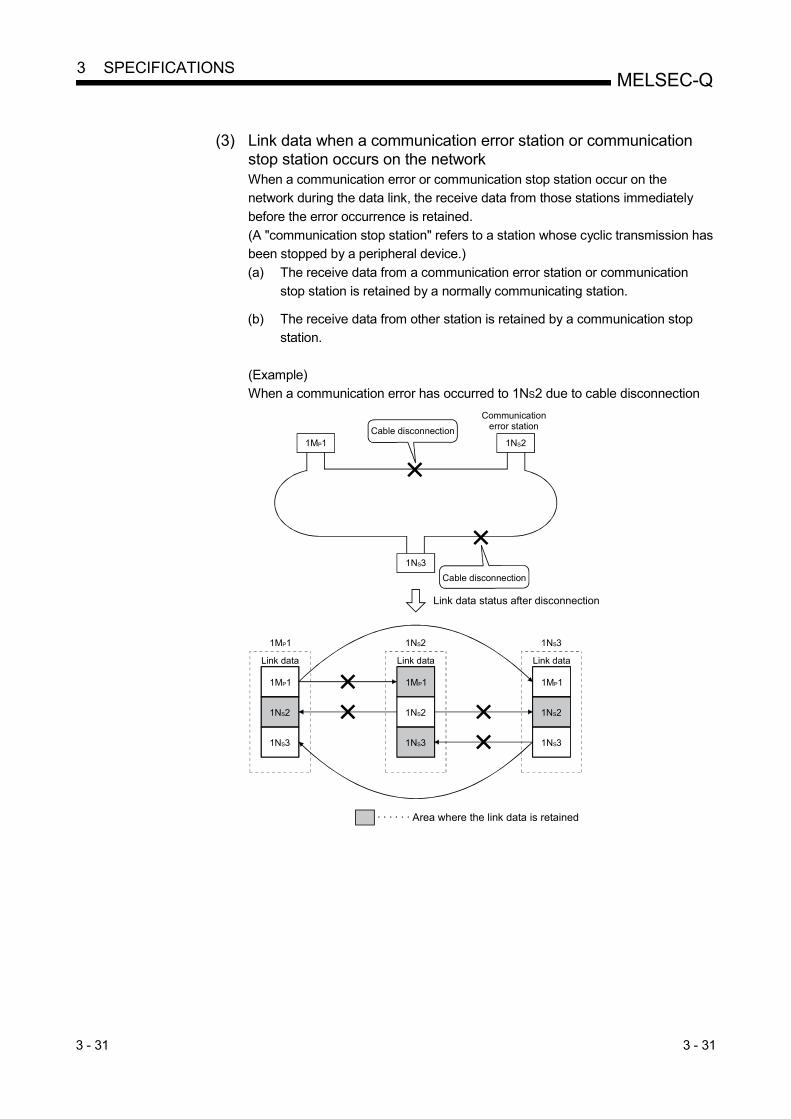
3 - 31 3 - 31
MELSEC-Q 3 SPECIFICATIONS
(3) Link data when a communication error station or communication
stop station occurs on the network When a communication error or communication stop station occur on the network during the data link, the receive data from those stations immediately
before the error occurrence is retained.
(A "communication stop station" refers to a station whose cyclic transmission has been stopped by a peripheral device.)
(a) The receive data from a communication error station or communication
stop station is retained by a normally communicating station.
(b) The receive data from other station is retained by a communication stop station.
(Example) When a communication error has occurred to 1NS2 due to cable disconnection
1NS3
1MP1 1NS2Cable disconnection
Communication error station
1MP1
1NS2
1NS3
1NS2
1MP1
1NS2
1NS3
1MP1
1NS2
1NS3
· · · · · · Area where the link data is retained
1MP1 1NS3
Link data status after disconnection
Link data Link data Link data
Cable disconnection

3 - 32 3 - 32
MELSEC-Q 3 SPECIFICATIONS
(4) SB/SW when a communication error station/communication stop
station occurs on the network The status of whether there are any communication error/communication stop stations on the network can be checked with the link special relay/link special
register (SB/SW).
Use them as interlocks for programs. For interlock program examples, refer to Section 6.1.2.
Link special relays and registers
Link special
relay/link
special
register
Description
Signal status
Off On
SB0020 Shows the communication status between the
network module and CPU module. Normal Abnormal
SB0047 Shows the baton pass execution status of the host.
The baton
pass is being
executed
The baton
pass is
stopped
SB0049 Shows the cyclic transmission status of the host. Normal Abnormal
SB0070
Shows the baton pass execution status of all
stations (including the host). However, it only shows
the status for the number of stations set with
parameters.
The baton
pass is being
executed on
all stations
Occurrence
of
communicati-
on stop
station
SW0070 to
0073
Shows the baton pass execution status of each
station.
Each bit corresponds to the status of each station.
The baton
pass is being
executed
The baton
pass is
stopped
SB0074
Shows the cyclic transmission status of all stations
(including the host). However, it only shows the
status for the number of stations set with
parameters.
All stations
normal
Occurrence
of abnormal
station
SW0074 to
0077
Shows the cyclic transmission status of each station.
Each bit corresponds to the status of each station. Normal Abnormal
SB007A,
007B
Shows the low-speed cyclic transmission status.
The transmission completion is indicated by the
on/off status of either bit SB007A or 007B.
SB007A
SB007B
Low-speed cyclic interval
SW01FC to
SW01FF
Indicates the redundant system status (control
system/standby system) of each station. Each bit
corresponds to the status of each station.
Control
system*1
Standby
system
*1: Signals for the stations in other than a redundant system are off.

3 - 33 3 - 33
MELSEC-Q 3 SPECIFICATIONS
3.3.2 How to calculate the transmission delay time
(1) Transmission delay time in the same network (a) Cyclic transmission (LB/LW/LX/LY periodical communication)
The transmission delay time in the B/W/Y communication is obtained by the
equation below using the following variables: • Scan time for the sending and receiving stations (except link refresh time) • Link refresh time • Link scan time • Tracking time • Scan time delay due to tracking transfer
[Transmission delay time (TD1) in B/W/Y communication]
1) When a non-redundant CPU receives data
2) When a redundant CPU receives data
TD1 = ST + T + (LS 0.5) + (SR + R) 1.5 [ms](MAX : TD1 = ST + T + (LS 1) + (SR + R) 2)
TD1 = ST + T + (LS 0.5) + (SR + R + Ts) 1.5 [ms](MAX : TD1 = ST + T + (LS 1) + (SR + R + Ts) 2)
ST : Scan time of the sending station (except link refresh time)
SR : Scan time of the receiving station (except link refresh time)
T : Link refresh time of the sending station 1 R : Link refresh time of the receiving station 1
LS : Link scan time
Ts : Scan time delay due to tracking transfer 2 1: Total of installed network modules
2: For the scan time delay due to tracking transfer, refer to the
QnPRHCPU User's Manual (Redundant System). The equation above assumes the following conditions: • There is no faulty station. • The transient transmission is not executed.
POINT
(1) For the transmission delay time in the B/W/Y communication (TD1), use the
equation for the "MAX" if the worst conditions coincide because the scan of the
sequence program and the link scan are asynchronous. (2) When the "Block send/receive data assurance per station" boxes is checked,
add the following delay time to the transmission delay time (TD1).
• In the case of ST >LS Normal : Add "+ 0.5 (ST + T)"
MAX : Add "+ 1.0 (ST + T)"
• In the case of ST <LS Normal : Add "+ 0.5 LS"
MAX : Add "+ 1.0 LS"
(3) In the MELSECNET/H Extended mode, the "Block send/receive data assurance per station" boxes are preset by default. Therefore, add any of the values
shown in (2) above to the transmission delay time (TD1).
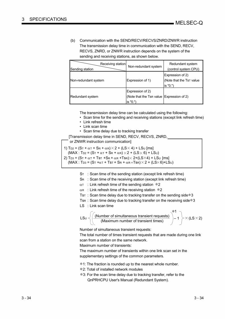
3 - 34 3 - 34
MELSEC-Q 3 SPECIFICATIONS
(b) Communication with the SEND/RECV/RECVS/ZNRD/ZNWR instruction
The transmission delay time in communication with the SEND, RECV,
RECVS, ZNRD, or ZNWR instruction depends on the system of the sending and receiving stations, as shown below.
Receiving station
Sending station Non-redundant system
Redundant system
(control system CPU)
Non-redundant system Expression of 1)
Expression of 2)
(Note that the TsT value
is "0.")
Redundant system
Expression of 2)
(Note that the TsR value
is "0.")
Expression of 2)
The transmission delay time can be calculated using the following: • Scan time for the sending and receiving stations (except link refresh time) • Link refresh time • Link scan time • Scan time delay due to tracking transfer
[Transmission delay time in SEND, RECV, RECVS, ZNRD, or ZNWR instruction communication]
1) TD2 = (ST + T + SR + R) 2 + (LS 4) + LSU [ms] (MAX : TD2 = (ST + T + SR + R) 2 + (LS 6) + LSU)2) TD3 = (ST + T + TsT +SR + R +TsR) 2+(LS 4) + LSU [ms] (MAX : TD3 = (ST +T + TsT + SR + R TsR) 2 + (LS 6)+LSU)
ST : Scan time of the sending station (except link refresh time)
SR : Scan time of the receiving station (except link refresh time) T : Link refresh time of the sending station 2
R : Link refresh time of the receiving station 2
TsT : Scan time delay due to tracking transfer on the sending side 3 TsR : Scan time delay due to tracking transfer on the receiving side 3
LS : Link scan time
LSU(Number of simultaneous transient requests)
(Maximum number of transient times)– 1
1
(LS 2)
Number of simultaneous transient requests:
The total number of times transient requests that are made during one link
scan from a station on the same network. Maximum number of transients:
The maximum number of transients within one link scan set in the
supplementary settings of the common parameters.
1: The fraction is rounded up to the nearest whole number. 2: Total of installed network modules
3: For the scan time delay due to tracking transfer, refer to the
QnPRHCPU User's Manual (Redundant System).

3 - 35 3 - 35
MELSEC-Q 3 SPECIFICATIONS
REMARKS
When executing transient transmissions from multiple stations at the same time, the
execution time of the instruction may be shortened by increasing the setting value
for the maximum number of transient requests in one link scan. For instance, when there are seven stations that execute an instruction, the time for
"LS 4" may be shortened by changing the setting value of the maximum transient
requests from the default value of two to seven or larger with the transient setting in the supplementary settings of the common parameters of GX Developer.
Note, however, that the scan time of the CPU module increases by that time amount.
(c) READ, WRITE, REQ, RRUN, RSTOP, RTMRD, or RTMWR instruction
communication
The transmission delay time in communication with the READ, WRITE, REQ, RRUN, RSTOP, RTMRD, or RTMWR instruction depends on the system of the
sending and receiving stations.
Receiving
station
Sending
station
Non-redundant
system
Redundant system
Host system Other system
Access to control
system CPU
Access to standby
system CPU
Access to standby
system CPU via
control system
Access to control
system CPU via
standby system
Non-redundant
system
Expression of 1) Expression of 2)
(Note that the TsT
value is "0.")
Expression of 2)
(Note that the
values of TsT, SR,
and αR are "0.")
Expression of 3)
(Note that the TsT
value is "0.")
Expression of 3)
(Note that the
values of TsT, SR,
and αR are "0.")
Redundant system Expression of 2)
(Note that the TsR
value is "0.")
Expression of 2) Expression of 2)
(However, the
values of SR, and
αR are "0.")
Expression of 3) Expression of 3)
(Note that the
values of SR, and
αR are "0.")
The transmission delay time in instruction communication can be calculated from the following:
• Scan time of the sending and receiving stations (except link refresh time)
• Link refresh time • Link scan time
• Scan time delay due to tracking transfer [Transmission delay time in READ/WRITE/REQ/RRUN/RSTOP/ RTMRD/RTMWR instruction communication]
3) TD6 = (ST + T + TsT +SR + R +TsR) 2 (LS 4) + 3 + LSU [ms] (MAX : TD6 = (ST +T + TsT + SR + R TsR) 2 (LS 6) + 6 + LSU)
1) TD4 = (ST + T + SR + R) 2 + (LS 4) + LSU [ms] (MAX : TD4 = (ST + T + SR + R) 2 + (LS 6) + LSU)2) TD5 = (ST + T + TsT +SR + R +TsR) 2 (LS 4) + LSU [ms] (MAX : TD5 = (ST +T + TsT + SR + R TsR) 2 + (LS 6) + LSU)
(To next page)

3 - 36 3 - 36
MELSEC-Q 3 SPECIFICATIONS
ST : Scan time of the sending station (except link refresh time)
SR : Scan time of the receiving station 1 (except link refresh time)
T : Link refresh time of the sending station 2 R : Link refresh time of the receiving station 2
LS : Link scan time
TsT : Scan time delay due to tracking transfer on the sending side 4 TsR : Scan time delay due to tracking transfer on the receiving side 4
LSU(Number of simultaneous transient requests)
(Maximum number of transient times)– 1
3
(LS 2)
Number of simultaneous transient requests:
The total number of times transient requests that are made during one link scan from a station on the same network.
Maximum number of transients:
The maximum number of transients within one link scan set in the supplementary settings of the common parameters.
1: For the redundant system, it is a scan time of the control system CPU.
2: Total time for the installed network modules.
3: The fraction is rounded up to the nearest whole number. 4: For the scan time delay due to tracking transfer, refer to the
QnPRHCPU User's Manual (Redundant System).
REMARKS
When executing transient transmissions from multiple stations at the same time, the
execution time of the instruction may be shortened by increasing the setting value
for the maximum number of transient requests in one link scan. For instance, when 7 stations are supposed to execute an instruction, the time for
"LS 4" may be shortened by changing the setting value of the maximum transient
requests from the default value of 2 to 7 or larger in the transient setting in supplementary settings of Common parameters from GX Developer.
Note, however, that the scan time of the CPU module increases by that time amount.
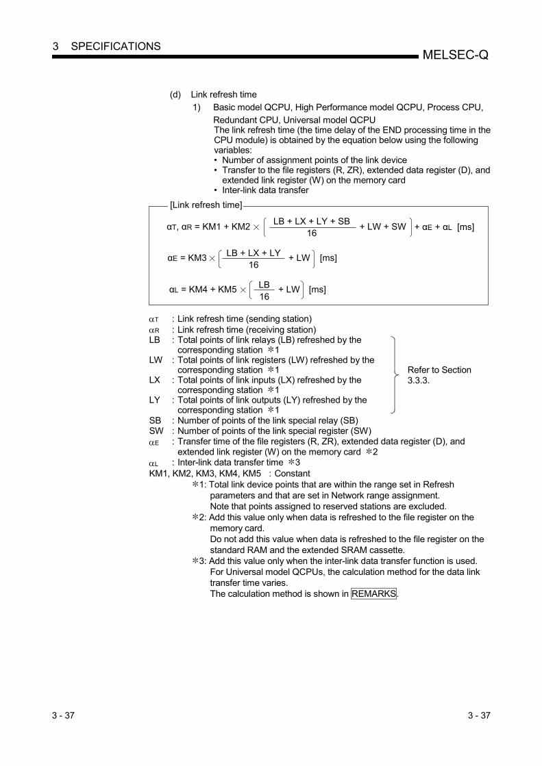
3 - 37 3 - 37
MELSEC-Q 3 SPECIFICATIONS
(d) Link refresh time
1) Basic model QCPU, High Performance model QCPU, Process CPU,
Redundant CPU, Universal model QCPU The link refresh time (the time delay of the END processing time in the CPU module) is obtained by the equation below using the following variables: • Number of assignment points of the link device • Transfer to the file registers (R, ZR), extended data register (D), and
extended link register (W) on the memory card • Inter-link data transfer
[Link refresh time]
αT, αR = KM1 + KM2 + LW + SWLB + LX + LY + SB16
αE = KM3 LB + LX + LY16
+ LW
αL = KM4 + KM5 LB16
+ LW
[ms]
[ms]
+ αE + αL [ms]
T : Link refresh time (sending station) R : Link refresh time (receiving station) LB : Total points of link relays (LB) refreshed by the
corresponding station 1
Refer to Section 3.3.3.
LW : Total points of link registers (LW) refreshed by the corresponding station 1
LX : Total points of link inputs (LX) refreshed by the corresponding station 1
LY : Total points of link outputs (LY) refreshed by the corresponding station 1
SB : Number of points of the link special relay (SB) SW : Number of points of the link special register (SW) E : Transfer time of the file registers (R, ZR), extended data register (D), and
extended link register (W) on the memory card 2 L : Inter-link data transfer time 3 KM1, KM2, KM3, KM4, KM5 : Constant
1: Total link device points that are within the range set in Refresh parameters and that are set in Network range assignment. Note that points assigned to reserved stations are excluded.
2: Add this value only when data is refreshed to the file register on the memory card. Do not add this value when data is refreshed to the file register on the standard RAM and the extended SRAM cassette.
3: Add this value only when the inter-link data transfer function is used. For Universal model QCPUs, the calculation method for the data link transfer time varies. The calculation method is shown in REMARKS.

3 - 38 3 - 38
MELSEC-Q 3 SPECIFICATIONS
• When network modules are installed on the main base unit
Constant
CPU type KM1
(×10-3
)
KM2
(×10-3
)
KM3
(×10-3
)
KM4
(×10-3
)
KM5
(×10-3
)
Basic model QCPU Q00JCPU 1300 0.67 Q00CPU 1100 0.66 Q01CPU 900 0.61
High Performance model QCPU
Q02CPU 300 0.48 0.60 600 140 Q02H/Q06H/Q12H/Q25HCPU 130 0.41 0.53 250 130
Process CPU Q02PH/Q06PH/Q12PH/ Q25PHCPU
130 0.41 0.53 250 130
Redundant CPU Q12PRH/Q25PRHCPU 130 0.41 0.53 250 130
Universal model QCPU
Q00UJ/Q00U/Q01UCPU 160 0.41
The calculation method of inter-link data transfer time differs. (Refer to Remarks.)
Q02UCPU 160 0.41 0.39 Q03UD/Q03UDECPU 90 0.41 0.39 Q04UDH/Q04UDEH/ Q06UDH/Q06UDEH/ Q10UDH/Q10UDEH/ Q13UDH/Q13UDEH/ Q20UDH/Q20UDEH/ Q26UDH/Q26UDEH/ Q50UDEH/Q100UDEHCPU
90 0.41 0.33
Q03UDV/Q04UDV/Q06UDV/ Q13UDV/Q26UDVCPU
45 0.41
• When network modules are installed on the extension base unit
Constant
CPU type KM1
(×10-3
)
KM2
(×10-3
)
KM3
(×10-3
)
KM4
(×10-3
)
KM5
(×10-3
)
Basic model QCPU Q00JCPU 1300 1.50 Q00CPU 1100 1.44 Q01CPU 900 1.42
High Performance model QCPU
Q02CPU 300 1.20 1.32 610 280 Q02H/Q06H/Q12H/Q25HCPU 130 0.97 1.09 270 260
Process CPU Q02PH/Q06PH/Q12PH/ Q25PHCPU
130 0.97 1.09 270 260
Redundant CPU Q12PRH/Q25PRHCPU
Universal model QCPU
Q00UJ/Q00U/Q01UCPU 160 1.06
The calculation
method of inter-link
data transfer time
differs. (Refer to
Remarks.)
Q02UCPU 160 1.06 0.39 Q03UD/Q03UDECPU 90 0.97 0.39 Q04UDH/Q04UDEH/ Q06UDH/Q06UDEH/ Q10UDH/Q10UDEH/ Q13UDH/Q13UDEH/ Q20UDH/Q20UDEH/ Q26UDH/Q26UDEH/ Q50UDEH/Q100UDEHCPU
90 0.97 0.33
Q03UDV/Q04UDV/Q06UDV/Q13UDV/Q26UDVCPU
45 0.97

3 - 39 3 - 39
MELSEC-Q 3 SPECIFICATIONS
2) Safety CPU
T , R 1 .8 5 LB + LX + LY + SB
16+ LW + 1000 10-3 [ms]
[Link refresh time]
=
T : Link refresh time (sending station) R : Link refresh time (receiving station) LB : Total points of link relays (LB) refreshed by the
corresponding station 1
Refer to Section 3.3.3.
LW : Total points of link registers (LW) refreshed by the corresponding station 1
LX : Total points of link inputs (LX) refreshed by the corresponding station 1
LY : Total points of link outputs (LY) refreshed by the corresponding station 1
SB : Number of points of the link special relay (SB) SW : Number of points of the link special register (SW)
1: Total points are the sum of link devices set in refresh parameter settings and network range settings. The points assigned for reserved station are not included.
POINT
The values in this section are calculated on the basis that data are received from all stations during one sequence scan.
When the link scan is long or when the sequence scan is short, data from all
stations may not be received within one sequence scan. If this occurs, the actual link refresh time is less than the calculated value shown in
this section.

3 - 40 3 - 40
MELSEC-Q 3 SPECIFICATIONS
REMARKS
(1) Data link transfer time (for Universal model QCPU) Universal model QCPUs transfer interlink data in several batches.
The following are the calculation formulas for the data link transfer time.
(a) Data link transfer time taken in one END
αL = KM4 + (KM5 × n1) + +LWT × KM6 [ms]LBT
16*1
L : Data link transfer time taken in one END n1 : Number of lines where interlink transmission parameters are set LBT : Total number of link relay (LB) points set in interlink transmission
parameters LWT : Total number of link register (LW) points set in interlink transmission
parameters KM4, KM5, KM6: Constants
1: The number of words that can be transferred in one END (N) is
restricted as follows:
N = Sequence scan time (under no interlink transmission parameter setting) (s) 0.05
CPU type KM4(×10-3
) KM5(×10-3
)
Q00UJ/Q00U/Q01UCPU
Q02UCPU 120 11
Q03UD/Q03UDECPU 34 16.3 Q04UDH/Q04UDEH/ Q06UDH/Q06UDEH/ Q10UDH/Q10UDEH/ Q13UDH/Q13UDEH/ Q20UDH/Q20UDEH/ Q26UDH/Q26UDEH/ Q50UDEH/Q100UDEHCPU
25 16.3
Q03UDV/Q04UDV/Q06UDV/Q13UDV/Q26UDVCPU 12 4
CPU type
KM6(×10-3)
Network module mounting position
Source (main base) →
Target (main base)
Source (main base) →
Target (extension base)
Source (extension base)
→
Target (main base)
Source (extension base)
→
Target (extension base)
Q00UJ/Q00U/Q01UCPU
Q02UCPU 0.76 1.27 1.37 1.79
Q03UD/Q03UDECPU 0.73 1.27 1.37 1.78 Q04UDH/Q04UDEH/ Q06UDH/Q06UDEH/ Q10UDH/Q10UDEH/ Q13UDH/Q13UDEH/ Q20UDH/Q20UDEH/ Q26UDH/Q26UDEH/ Q50UDEH/Q100UDEHCPU
0.73 1.25 1.35 1.78
Q03UDV/Q04UDV/Q06UDV/
Q13UDV/Q26UDVCPU 0.73 1.27 1.37 1.78

3 - 41 3 - 41
MELSEC-Q 3 SPECIFICATIONS
(b) Data link transfer time required for transferring data of all the set points
αL1 = KM7× +LWT [ms]LBT
16 L1 : Data link transfer time taken to transfer all the set points of data LBT : Total number of link relay (LB) points set in interlink transmission
parameters LWT : Total number of link register (LW) points set in interlink transmission
parameters KM7: Constants
CPU type
KM7( 10-3
)
Network module mounting position
Source (main base)
Target (main base)
Source (main base)
Target (extension base)
Source (extension base)
Target (main base)
Source (extension base)
Target (extension base)
Q00UJ/Q00U/Q01UCP 25.00 25.20 25.20 25.50
Q02UCPU 25.00 25.20 25.20 25.50
Q03UD/Q03UDECPU 22.10 22.50 22.70 23.00
Q04UDH/Q04UDEH/
Q06UDH/Q06UDEH/
Q10UDH/Q10UDEH/
Q13UDH/Q13UDEH/
Q20UDH/Q20UDEH/
Q26UDH/Q26UDEH/
Q50UDEH/Q100UDEHCPU
22.10 22.50 22.70 23.00
Q03UDV/Q04UDV/Q06UDV/
Q13UDV/Q26UDVCPU 22.10 22.50 22.70 23.00
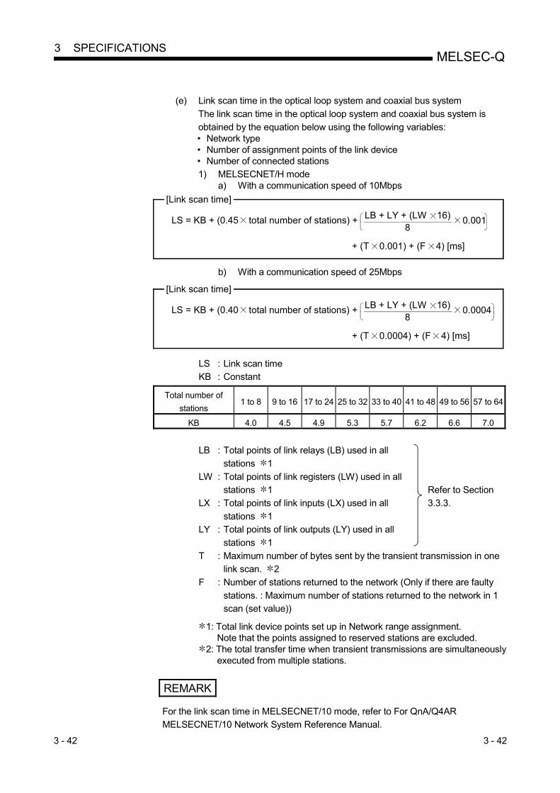
3 - 42 3 - 42
MELSEC-Q 3 SPECIFICATIONS
(e) Link scan time in the optical loop system and coaxial bus system
The link scan time in the optical loop system and coaxial bus system is
obtained by the equation below using the following variables: • Network type • Number of assignment points of the link device • Number of connected stations 1) MELSECNET/H mode
a) With a communication speed of 10Mbps [Link scan time]
LS = KB + (0.45 total number of stations) +
+ (T 0.001) + (F 4) [ms]
0.001LB + LY + (LW 16)8
b) With a communication speed of 25Mbps
[Link scan time]
LS = KB + (0.40 total number of stations) +
+ (T 0.0004) + (F 4) [ms]
0.0004LB + LY + (LW 16)8
LS : Link scan time KB : Constant
Total number of
stations 1 to 8 9 to 16 17 to 24 25 to 32 33 to 40 41 to 48 49 to 56 57 to 64
KB 4.0 4.5 4.9 5.3 5.7 6.2 6.6 7.0
LB : Total points of link relays (LB) used in all
stations 1
Refer to Section
3.3.3.
LW : Total points of link registers (LW) used in all stations 1
LX : Total points of link inputs (LX) used in all
stations 1 LY : Total points of link outputs (LY) used in all
stations 1
T : Maximum number of bytes sent by the transient transmission in one link scan. 2
F : Number of stations returned to the network (Only if there are faulty
stations. : Maximum number of stations returned to the network in 1 scan (set value))
1: Total link device points set up in Network range assignment.
Note that the points assigned to reserved stations are excluded. 2: The total transfer time when transient transmissions are simultaneously
executed from multiple stations.
REMARK
For the link scan time in MELSECNET/10 mode, refer to For QnA/Q4AR MELSECNET/10 Network System Reference Manual.

3 - 43 3 - 43
MELSEC-Q 3 SPECIFICATIONS
2) MELSECNET/H Extended mode
a) With a communication speed of 10Mbps [Link scan time]
LS = KB + (0.45 SP) +
+ (T 0.001) + (F 4) [ms]
0.001LB + LY + (LW 16)8
b) With a communication speed of 25Mbps [Link scan time]
LS = KB + (0.40 SP) +
+ (T 0.0004) + (F 4) [ms]
0.0004LB + LY + (LW 16)8
LS : Link scan time KB : Constant
Total number of stations
1 to 8 9 to 16 17 to 24 25 to 32 33 to 40 41 to 48 49 to 56 57 to 64
KB 4.0 4.5 4.9 5.3 5.7 6.2 6.6 7.0
SP=Number of bytes sent by station No. (i)
2000
n
i=1
n=Total number of stations
Station No.
Station No. 1
Station No. 2
Station No. 3
Station No. 4
8000 bytes
7800 bytes
0 bytes
2000 bytes
a Setting example
The calculation example of SP in the setting example is shown in .a b
1: The number after the decimal point is rounded up. 0 is handled as 1.
1
b Calculation example of SP
SP= 80002000
+ 78002000
02000
20002000
=4 + 4 + 1 + 1
Number after decimal point is rounded up.
0 is handled as 1.
=10
+ +Number of bytes sent by each station
Number of bytes sent = {(LY + LB) / 8 + (2 x LW)}
LB : Total points of link relays (LB) used in all
stations 2
Refer to Section
3.3.3.
LW : Total points of link registers (LW) used in all stations 2
LX : Total points of link inputs (LX) used in all
stations 2 LY : Total points of link outputs (LY) used in all
stations 2
T : Maximum number of bytes sent by the transient transmission in one link scan. 3
F : Number of stations returned to the network (Only if there are faulty
stations. : Maximum number of stations returned to the network in 1 scan (set value))
2: Total link device points set up in the network range parameter assignment. Note that the points assigned to reserved stations are excluded.
3: "0" when not used.

3 - 44 3 - 44
MELSEC-Q 3 SPECIFICATIONS
(f) Link scan time in the twisted bus system
The link scan time in the twisted bus system is obtained by the equation
below using the following variables: • Network type
• Number of assignment points of the link device
• Constant 1 to 3 1) MELSECNET/H mode
[Link scan time]
LS = KB1+(KB2 total number of stations) + KB3
+ (T KB3) + (F 4) [ms]
LB+LX+(LW 16)8
2) MELSECNET/H Extended mode
LB+LX+(LW 16)8
[Link scan time]
LS = KB1+(KB2 SP) + KB3 + (T KB3) + (F 4) [ms]
LS : Link scan time
KB1 to 3: Constant Total number of stations 1 to 8 9 to 16 17 to 24 25 to 32
KB1 8.0 8.5 8.9 9.3
Communication speed 156kbps 312kbps 625kbps 1.25Mbps 2.5Mbps 5Mbps 10Mbps
KB2 4.6 3.83 3.06 2.55 2.05 1.55 1.05
Communication speed 156kbps 312kbps 625kbps 1.25Mbps 2.5Mbps 5Mbps 10Mbps
KB3 0.064 0.032 0.016 0.008 0.004 0.002 0.001
LB : Total points of link relays (LB) used in all stations 1
Refer to Section 3.3.3.
LW : Total points of link registers (LW) used in all
stations 1 LX : Total points of link inputs (LX) used in all
stations 1
LY : Total points of link outputs (LY) used in all stations 1
T : Maximum number of bytes sent by the transient transmission in one
link scan. 2 F : Number of stations returned to the network (Only if there are faulty
stations. : Maximum number of stations returned to the network in 1
scan (set value)) SP : Refer to Section 3.3.3 (e).
1: Total link device points set up in the network range parameter assignment. Note that the points assigned to reserved stations are excluded.
2: "0" when not used.

3 - 45 3 - 45
MELSEC-Q 3 SPECIFICATIONS
(2) Transmission delay time between multiple networks using the inter-
link data transfer function The following shows the cyclic transmission delay time for the case where link device data are transferred to another network with the interlink transfer function.
[Inter-link data transfer]
(Transmission delay time)
TD = (ST + T) + (LST 1) + MR + KM + MT + (LSR 1) + (SR 2) + R [ms]
(Transmission delay time)...For Universal model QCPU
TD = (ST + T) + (LST 1) + MR + MT + (LSR 1) + (SR 2) + R [ms]
ST : Scan time of the sending station (except link refresh time)
SR : Scan time of the receiving station (except link refresh time)
T : Link refresh time of the transmitting station 1 MT : Link refresh time of the relay station and the sending station (for transfer) 1
MR : Link refresh time of the relay station and the receiving station (for transfer) 1
R : Link refresh time of the receiving station 1 LST : Link scan time of the sending station
LSR : Link scan time of the receiving station
KM : Transmission processing time of the CPU module of the relay station 1: Total for the network modules mounted
KM = KM6LB
161000 + KM7 [ms]+ LW
LB : Total of transfer source LB points that are set with interlink transmission parameters.
LW : Total of transfer source LW points that are set with interlink transmission
parameters. KM6 : Constant
KM7 : 4.5 (Worst value: 60)
Module location KM6 ( 10-3)
Transfer source module Transfer target module
Main base unit Main base unit 6.7
Main base unit Extension base unit 10.00
Extension base unit Main base unit 10.00
Extension base unit Extension base unit 12.00
POINT
Although KM7 is usually 4.5ms, it can be 60ms if monitoring or a dedicated
instruction is executed from GX Developer or any other station.
Depending on the monitoring timing from GX Developer or another station, the time may be longer than that.
If the time increase may cause a system problem, use link direct devices in the
sequence program to transfer data.

3 - 46 3 - 46
MELSEC-Q 3 SPECIFICATIONS
(3) Example of the transmission delay time calculation
The following example calculates the transmission delay time with the following
system configuration and under the following conditions:
(System configuration and conditions) 1) CPU module: Q06HCPU
2) Network type: MELSECNET/H mode
3) Communication speed: 10Mbps 4) Total number of stations: 8 stations (1 control station, 7 normal
stations)
5) Number of link device points: LB = 1024 points, LW = 1024 points, LX = LY = 0 points, SB = SW = 512 points
6) Scan time of the CPU module for all stations: 1 ms
7) The file register is not used. 8) The data inter-link transfer and the transient transmission are not used.
9) The network modules are installed on the basic base unit on all
stations. <Constants used when network modules are installed on main base unit>
Constant
CPU type KM1
(×10-3
)
KM2
(×10-3
)
KM3
(×10-3
)
KM4
(×10-3
)
KM5
(×10-3
)
Q06HCPU 130 0.41 0.53 250 130
(a) Link refresh time
Link refresh time = KM1 + KM2 × LB + LX +LY + SB16
The link refresh time on the sending station αT = 130 × 10-3 + 0.41 × 10⁻³
×
The link refresh time on the receiving station αR 0.80 (ms)
+ 1024 + 512 + 0 + 01024 + 0 + 0 + 51216
+ αE + αL+ LW + SW
0.80 (ms)
(b) Link scan time
= 4.0 + (0.45 8)
Link scan time LS = KB + (0.45 total number of stations)
(LB + LY + (LW 16)8
0.001
1024 + 0 + (1024 16)8
0.001
+
+
9.776 (ms)=
(c) Cyclic transmission delay
Transmission delay time TD1 = ST + T + (LS 0.5) + (SR + R) 1.5
= 1 + 0.80 + (9.776 0.5) + (1 + 0.80) 15 = 9.39 (ms)

3 - 47 3 - 47
MELSEC-Q 3 SPECIFICATIONS
3.3.3 Reducing the link refresh time
The link refresh time can be reduced by decreasing the number of refresh points to the CPU module.
Reduce the refresh points by any of the following:
• Refresh parameters • Common parameters
• Direct access to link devices
• Station inherent parameters
(1) Concept of the refresh range (number of points) The ranges set with common parameters and within the set range of Refresh parameters are refreshed.
Network module
Range set withcommonparameters
Range that isactuallyrefreshed
QCPU
DeviceStation inherentparameters
Commonparameters
1NS2
1MP1
1NS3
Empty
Empty
1NS2
1MP1
1NS3
Empty
Empty
LinkRefresh
LinkRefresh
LinkRefresh
Range set inRefresh parameters
POINT
(1) During the initial settings (to return to the initial settings, click the default
button of GX Developer) of the refresh parameters, the range from the start to
end addresses is set, which can be viewed with the assignment image figure of the refresh parameters.
(2) The initial settings of the station inherent parameters are the same as the
setting range of the common parameters.

3 - 48 3 - 48
MELSEC-Q 3 SPECIFICATIONS
(2) How to decrease the number of refresh points
(a) Using the refresh parameters Set the values so that only the required parts are refreshed. For more details, refer to Section 5.7.1.
Commonparameters
1NS2
1MP1
1NS3
Range set withcommon parameters
Set refresh parametersonly for necessaryareas
QCPU
Linkrefresh
Device
Network module
Linkrefresh
Linkrefresh

3 - 49 3 - 49
MELSEC-Q 3 SPECIFICATIONS
(b) Using direct access to link devices
The refresh time can be reduced by directly accessing link devices that are
less frequently used by the host and excluding them from the refresh range. (Refer to Section 7.1)
CPU
Link refresh
Network module
Link refresh
Direct access
Direct access
Range of sending to other stations
Range of receiving from other stations
Less frequently used link devices (read/write only as needed)
Frequently used link devices (read/write always required)

3 - 50 3 - 50
MELSEC-Q 3 SPECIFICATIONS
The link refresh is executed by the END processing of the CPU module, but
reading from/writing to the network module is directly performed when an
instruction is executed; thus the transmission delay time can be reduced.
1) Direct access to the sending station a) When close to step 0
The direct access is faster by a maximum of one scan of a sequence program when compared with the link refresh. (Link refresh)
Sequence scan 0 END
Link scan
0 END
B0
(Direct access)
Sequence scan 0 END
Link scan
0 END
J1\B0Same status as the END processing was executed
b) When close to END The link refresh and the direct access occur at almost the same time. (Link refresh)
Sequence scan 0 END
Link scan
0 END
B0
(Direct access)
Sequence scan 0 END
Link scan
0 END
J1\B0
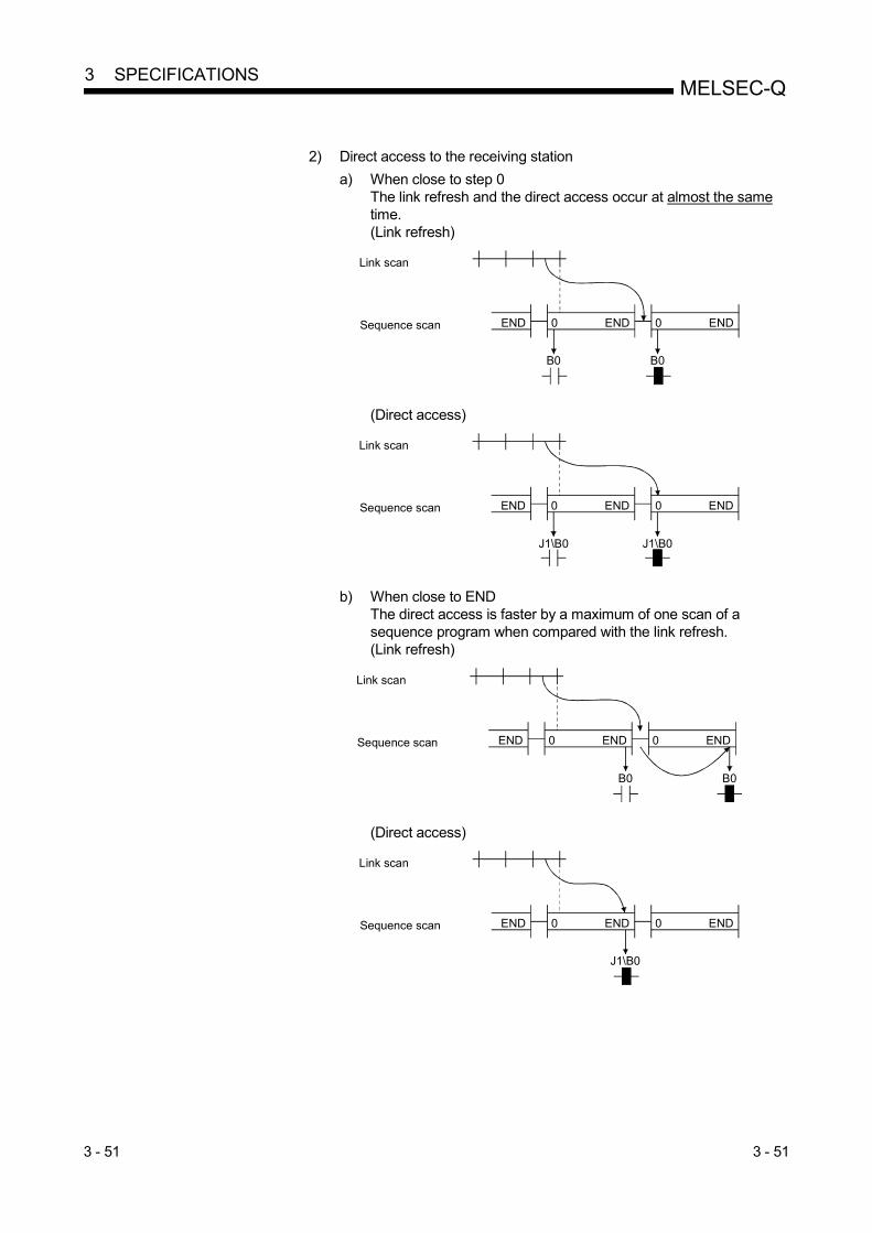
3 - 51 3 - 51
MELSEC-Q 3 SPECIFICATIONS
2) Direct access to the receiving station
a) When close to step 0 The link refresh and the direct access occur at almost the same time. (Link refresh)
Sequence scan END
Link scan
0 END 0 END
B0 B0
(Direct access)
Sequence scan END
Link scan
0 END 0 END
J1\B0 J1\B0
b) When close to END The direct access is faster by a maximum of one scan of a sequence program when compared with the link refresh. (Link refresh)
Sequence scan END
Link scan
0 END 0 END
B0 B0
(Direct access)
Sequence scan END
Link scan
0 END 0 END
J1\B0

3 - 52 3 - 52
MELSEC-Q 3 SPECIFICATIONS
3.3.4 Reduction of the link scan time
The amount of link refresh and link scan data (LB/LW) per END processing can be reduced by assigning the data in the link devices (LB/LW) for normal cyclic
transmission, which does not require high-speed transmission, to the extension area
(2000H to 3FFFH), and transmit it by the low-speed cyclic transmission. (High Performance model QCPU, Process CPU, Redundant CPU, and Universal
model QCPU)
Common
parametersQ25HCPU
1MP1
1NS3
1NS2
1NS3
1NS2
1MP1
Link refresh
Normal cyclic transmission range
0
Low-speed cyclic transmission range
2000
3FFF
1MP1
1NS2
1NS3
1FFF
Low-speed link refresh
3.3.5 Control station shift time
The time required to shift the control station status (control station shift time) can be calculated from the following expression:
[Control station shift time (Csw)]
Csw=( 12) + ( 11) + ( 3) + 450 [ms]a b c
a : Number of normal stations after control station cut-off
b : Number of abnormal stations after control station cut-off
c : Set value of constant link scan (Refer to Section 5.4.)

4 - 1 4 - 1
MELSEC-Q 4 SETUP AND PROCEDURES BEFORE STARTING THE OPERATION
4 SETUP AND PROCEDURES BEFORE STARTING THE OPERATION
This chapter explains the procedures, settings, connections and testing that are required to start the data link operation.
4.1 Procedures Before Starting the Operation
The following flowchart shows the procedure for the data link operation: S ta rt
End
Programming and debugging
Standalone check of the network module
• Self-loopback test• Internal self-loopback test• Hardware test
Offline tests from GX Developer
• Station-to-station test• Forward loop/reverse loop test
Module installation
• Network module installation• CPU module halting (unintentional output prevention)• Input power supply voltage checking
Parameter settings
• Network type, start I/O No., network No., total stations• Send range assignment for each station, pairing setting, redundant settings, and other parameters• Writing parameters to the CPU module.
Network diagnostics from GX Developer
• Loop test (optical loop test only)• Setup confirmation test• Communication test, and other tests
Connect cables
· · · · · · Section 4.3
· · · · · · Section 4.5
· · · · · · Section 4.4Power on
• Turn on the power and check that the POWER LED of the power supply module and the RUN LED of the network module are turned on.
· · · · · · Chapter 5
· · · · · · Section 4.6
· · · · · · Section 4.7
· · · · · · Section 4.8
· · · · · · Chapter 6
Module switch setting
• Mode setting using the switch on the network module
· · · · · · Section 4.2
4

4 - 2 4 - 2
MELSEC-Q 4 SETUP AND PROCEDURES BEFORE STARTING THE OPERATION
4.2 Part Names and Settings
This section explains part names and settings of the network modules.
4.2.1 QJ71LP21, QJ71LP21-25, QJ71LP21S-25, QJ71LP21G, QJ71LP21GE
(4)
(4)
(3)
QJ71LP21, QJ71LP21-25
QJ71LP21G, QJ71LP21GEQJ71LP21S-25
(2)
(6)
(1)
(4)
(4)
(3)
(2)
(6)
(1)
(4)
(4)
(3)
(2)
(6)(5)
(1)
(1) Indicator LEDs
Name LED status Description
RUN ON (green) The module operating normally
OFF A watchdog timer error occurred (hardware failure).
MNG ON (green) Operating as a control station or sub-control station
OFF Normal station (not operating as a control station or sub-control station)
T.PASS ON (green) Executing baton pass (being joined in a network)
Flashing
(green)
The test is determined to have completed when this LED flashes 20 times or more (approximately
10s) during the test.
OFF Baton pass not yet executed (The host station is disconnected from the network.)
D.LINK ON (green) Data link being executed (Cyclic transmission is being executed.)
OFF Data link not yet executed (e.g. parameter receiving not completed, host CPU error, data link stop
instructed)
SD ON (green) Data being sent
OFF Data not yet sent
RD ON (green) Data being received
OFF Data not yet received
ERR. ON (red) • An error, such as a station number setting error, mode setting error (set to use prohibited), operating condition setting error by parameter, and a mounted CPU type error (setting outside the range used, incorrect CPU type), occurred.
• A station with the same number already exists in the network. • Although a control station has already existed in the network, the host station is specified as a
control station. • Invalid parameter setting • The parameters received from the sub-control station and the parameters retained by the host
(received from the control station) are different. • A moderate or serious error occurred in the CPU module.
Flashing • An error was detected while the network module was being tested. • The setting of the mode setting switch or the station number setting switch was changed during
operation. 1
OFF Normal status
4

4 - 3 4 - 3
MELSEC-Q 4 SETUP AND PROCEDURES BEFORE STARTING THE OPERATION
Name LED status Description
L ERR. ON (red) A communication error occurred (one of the following communication errors has occurred):
CRC : An error was generated by a fault such as a cable error and noise.
OVER : This error occurs when the next data is received before the last receive data is loaded
into the module, and the previous data is lost. It is caused by hardware failure in the
receive area of the network module.
AB.IF : This error occurs when the number of receive bit data indicating "1" in the frame is
more than or equal to the specified number of data, or when the receive data is shorter
than the specified data length.
TIME : This error occurs when a baton pass was not handed to the host within the monitoring
time.
DATA : This error occurs when abnormal code data is received.
UNDER : This error occurs when the internal processing of the send data was not executed at a
fixed interval.
LOOP : This error occurs when the forward loop line or reverse loop line is faulty and the power
to the adjacent station, which sends data to the host station, is turned off or the
hardware of the sending station part in the loop is faulty.
<Corrective action>
Check the cables and connectors (e.g. disconnected or loosened connector, wrong
IN/OUT connection, disconnected cable, damaged connector/cable, improper cable
routing).
For details, refer to the network diagnostics (Section 8.1).
OFF No communication error
EXT. PW ON (green) External power being supplied (Power supply status of host (SB0042) is on.)
OFF External power not supplied (Power supply status of host (SB0042) is off.)
1: The ERR. LED flashes on the following modules whose serial No. (first five digits) is "02112" or later.
• QJ71LP21
• QJ71LP21-25
• QJ71BR11
(2) Station number setting switch
Used to set the station number of the network module. (Factory default: 1)
STATION NO.
10
1
10 10s unit
1 1s unit
Setting Description
0 Setting error
(The ERR. LED turns on.)
1 to 64 Station number 1 to 64
65 to 99 Setting error
(The ERR. LED turns on.)
POINT
(1) Station numbers cannot be duplicated in the same network.
(2) Any station can be set as the control station as long as the station number is
within the setting range.
(3) The station number can be set randomly. Note that stations with no number
assignment must be set as reserved stations.
(4) When setting, use a station number within the range set to "Total stations"
parameter of network parameter.

4 - 4 4 - 4
MELSEC-Q 4 SETUP AND PROCEDURES BEFORE STARTING THE OPERATION
(3) Mode setting switch
Used to set the mode of the network module. (Factory default: 0)
Set the mode setting switches in the same position on all network modules.
(a) QJ71LP21, QJ71LP21G, QJ71LP21GE
MODE
Setting Description
0 Online (The mode selected by the network parameter will be enabled.)
1 Self-loopback test
2 Internal self-loopback test
3 Hardware test
4 to F Use prohibited
(b) QJ71LP21-25, QJ71LP21S-25 Setting Description
0 Online (The mode selected by the network parameter will be
enabled.)
At 10Mbps 1 Self-loopback test
2 Internal self-loopback test
3 Hardware test
4 Online (The mode selected by the network parameter will be
enabled.)
At 25Mbps 5 Self-loopback test
6 Internal self-loopback test
7 Hardware test
8 to F Use prohibited
(4) IN and OUT connectors
An optical fiber cable connector is connected. (Refer to Section 4.6.1.)
Name
1) IN Forward loop receiving
2) IN Reverse loop sending
3) OUT Reverse loop receiving
4) OUT Forward loop sending
(5) External power supply terminal block
An external power supply is wired. (Refer to Section 4.6.1.)
(6) Serial number plate display
This display indicates the serial number of the rating plate.

4 - 5 4 - 5
MELSEC-Q 4 SETUP AND PROCEDURES BEFORE STARTING THE OPERATION
4.2.2 QJ71BR11
(1) Indicator LEDs
Same as the optical loop system. (Refer to Section 4.2.1.)
(2) Station number setting switch Used to set the station number of the network module. (Factory default: 1)
STATION NO.
10
1
10 10s unit
1 1s unit
Setting Description
0 Setting error
(The ERR. LED turns on.)
1 to 32 Station number 1 to 32
33 to 64 Setting error
(The ERR.LED will not turn on.)
65 to 99 Setting error
(The ERR. LED turns on.)
POINT (1) Station numbers cannot be duplicated in the same network. (2) Any station can be set as the control station as long as the station number is
within the setting range. (3) The station number can be set randomly. Note that stations with no number
assignment must be set as reserved stations. (4) When setting, use a station number within the range set to "Total stations"
parameter of network parameter.

4 - 6 4 - 6
MELSEC-Q 4 SETUP AND PROCEDURES BEFORE STARTING THE OPERATION
(3) Mode setting switch
Used to set the mode of the network module. (Factory default: 0)
Set the mode setting switches in the same position on all network modules.
MODE
Setting Description
0 Online (The mode selected by the network parameter will be enabled.)
1 Self-loopback test
2 Internal self-loopback test
3 Hardware test
4 to F Use prohibited
(4) Coaxial connector
An F-type connector for a coaxial cable is connected. (Refer to Section 4.6.2.) (5) Serial number display
This display indicates the serial number of the rating plate.

4 - 7 4 - 7
MELSEC-Q 4 SETUP AND PROCEDURES BEFORE STARTING THE OPERATION
4.2.3 QJ71NT11B
(1) Indicator LEDs
Same as the optical loop system. (Refer to Section 4.2.1.) (2) Station number/mode setting switch
Used to set the station number and mode of the network module. (Factory
default: 1)
Set the same operation mode to all network modules.
10 10s unit
1 1s unit
Setting Description
×10 ×1
0 0 Setting error
(The ERR. LED turns on.)
0 1
Station number 1 to 32 (online.) to
3 2
3 3 to 9 Setting error
(The ERR. LED turns on.) 1 • 0 to 9
TEST 0 to 6
TEST 7 Self-loopback test
TEST 8 Internal self-loopback test
TEST 9 Hardware test
1: The ERR. LED does not turn on in red if the station number is set equivalent to 33 to 64.
POINT
(1) Station numbers cannot be duplicated in the same network.
(2) Any station can be set as the control station as long as the station number is
within the setting range.
(3) The station number can be set randomly. Note that stations with no number
assignment must be set as reserved stations.
(4) When setting, use a station number within the range set to "Total stations"
parameter of network parameter.
(3) Spring clamp terminal block
Used to connect a shielded twisted pair cable or CC-Link Ver. 1.10-compatible
cable. (Refer to Section 4.6.3.) (4) Serial number display
This display indicates the serial number of the rating plate.
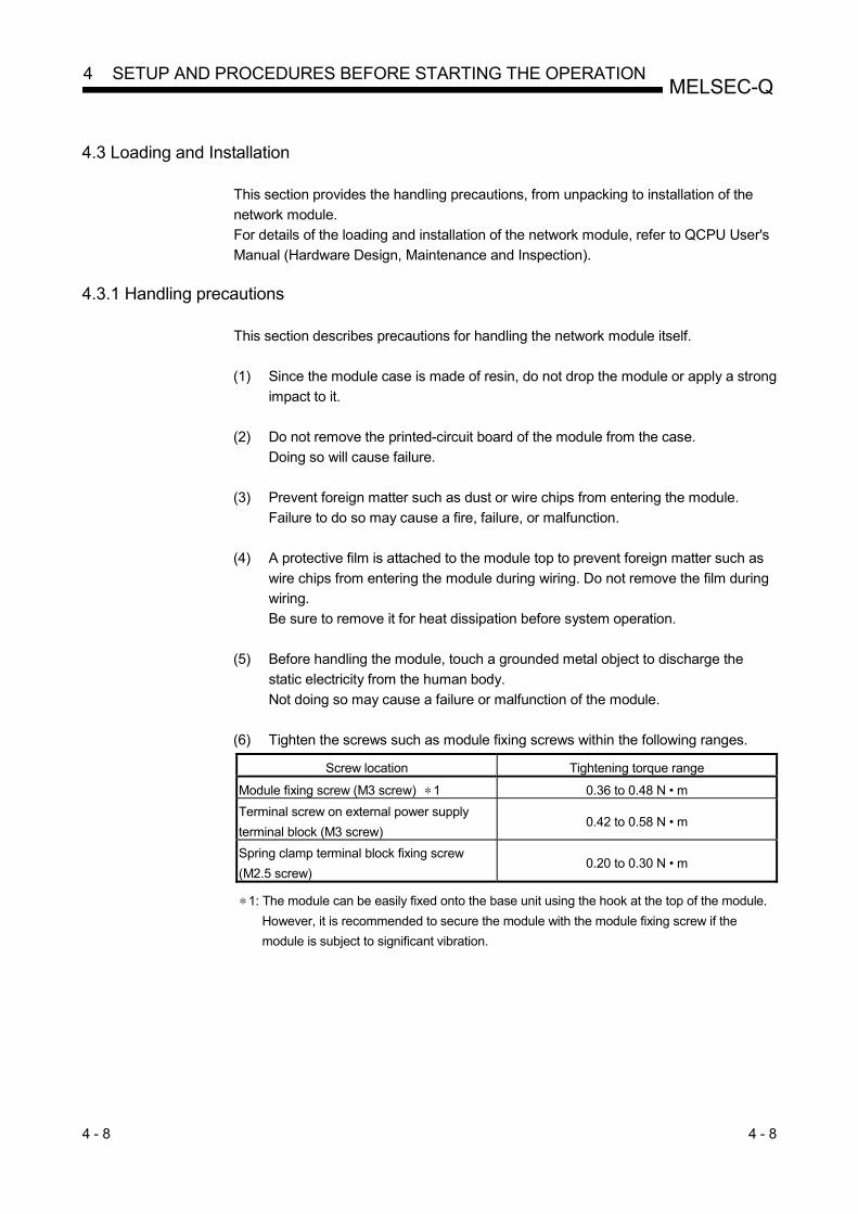
4 - 8 4 - 8
MELSEC-Q 4 SETUP AND PROCEDURES BEFORE STARTING THE OPERATION
4.3 Loading and Installation
This section provides the handling precautions, from unpacking to installation of the
network module.
For details of the loading and installation of the network module, refer to QCPU User's
Manual (Hardware Design, Maintenance and Inspection).
4.3.1 Handling precautions
This section describes precautions for handling the network module itself.
(1) Since the module case is made of resin, do not drop the module or apply a strong
impact to it.
(2) Do not remove the printed-circuit board of the module from the case.
Doing so will cause failure.
(3) Prevent foreign matter such as dust or wire chips from entering the module.
Failure to do so may cause a fire, failure, or malfunction.
(4) A protective film is attached to the module top to prevent foreign matter such as
wire chips from entering the module during wiring. Do not remove the film during
wiring.
Be sure to remove it for heat dissipation before system operation.
(5) Before handling the module, touch a grounded metal object to discharge the
static electricity from the human body.
Not doing so may cause a failure or malfunction of the module.
(6) Tighten the screws such as module fixing screws within the following ranges.
Screw location Tightening torque range
Module fixing screw (M3 screw) 1 0.36 to 0.48 N • m
Terminal screw on external power supply
terminal block (M3 screw) 0.42 to 0.58 N • m
Spring clamp terminal block fixing screw
(M2.5 screw) 0.20 to 0.30 N • m
1: The module can be easily fixed onto the base unit using the hook at the top of the module.
However, it is recommended to secure the module with the module fixing screw if the
module is subject to significant vibration.

4 - 9 4 - 9
MELSEC-Q 4 SETUP AND PROCEDURES BEFORE STARTING THE OPERATION
(7) Use drivers, which match the following recommended driver dimensions, for the
operation of the station number setting switch and the mode setting switch. Using
drivers with unsuitable edge width or thickness may damage the switches.
Screw location Tightening torque range
Edge width (L) 2.0 to 2.4 mm
Edge thickness (W) 0.5 to 0.6 mm

4 - 10 4 - 10
MELSEC-Q 4 SETUP AND PROCEDURES BEFORE STARTING THE OPERATION
4.3.2 Installing and uninstalling the module
(1) Installing the module
Fully insert the module fixinglatch into the module fixinghole in the base unit (exercisecare not to allow the modulefixing latch to separate fromthe module fixing hole).
Using the module fixing hole as a fulcrum, push the module in the direction of arrow to mount it into the base unit.
Check that the module issecurely fixed to thebase unit
Completed
Module fixing hole
Modulefixing latch
Base unit
Module fixinglever
Module
Module lockinghook
Base unit
Module fixing hole
Modulefixing lever
Module fixing latch
Module connector
Base unit
(2) Uninstalling the module
Hold the module by bothhands, and push the modulelocking hook on the top of themodule until it stops.
Pushing the module lockinghook, pull the module downward.
Lift the module to disengagethe module fixing latch fromthe module fixing hole.
Completed
Module
Moduleconnector
Module fixing hole
Base unit
Push.
Module lockinghook
Lift

4 - 11 4 - 11
MELSEC-Q 4 SETUP AND PROCEDURES BEFORE STARTING THE OPERATION
4.3.3 Stopping the CPU module (unintentional output prevention)
STOP RUN
Set the RUN/STOP switch *1 of the CPU module to STOP position.
*1: Use the RESET/STOP/RUN switch for the Basic model QCPU, Universal model
QCPU, and safety CPU.
4.3.4 Checking the input power supply voltage
Check that the power voltage supplied to the power supply module is within the
specifications.
4.4 Powering On
Check the power supply to the network module.
4.4.1 Checking the on status of the POWER LED of the power supply module
POWER
The POWER LED turns on at the same time when the programmable controller
system is powered on.
4.4.2 Checking the on status of the RUN LED of the network module
RUN MNG
T.PASS D.LINK
SD RD
ERR. L ERR.
The RUN LED turns on in green when the network module is operating normally.
If this LED does not turn on, refer to Chapter 8, "Troubleshooting."

4 - 12 4 - 12
MELSEC-Q 4 SETUP AND PROCEDURES BEFORE STARTING THE OPERATION
4.5 Standalone Check of the Network Module (Offline Tests)
Before executing the data link operation, check the network module and the cables.
Conduct an offline test following the procedure below.
Completed
Test start
Self-loopback test
Internal self-loopback test
Hardware test
Hardware of the network module is checkedincluding the transmission system send/receivecircuit and cables.(Refer to Section 4.5.1.)
Flow of offline tests
Hardware of the network module is checkedincluding the transmission system send/receive circuit.(Refer to Section 4.5.2.)
Hardware inside the network module is checked.(Refer to Section 4.5.3.)
REMARKS
• The data link operation cannot be executed normally if one station is in the test
mode (Self-loopback test, Internal self-loopback test, and Hardware test) during
data linking (online).
• For the test in offline mode, conduct by only the network module.

4 - 13 4 - 13
MELSEC-Q 4 SETUP AND PROCEDURES BEFORE STARTING THE OPERATION
4.5.1 Self-loopback test
This test checks the hardware of a standalone network module, including the send/receive circuit and cable of the transmission system.
POINT
Do not connect or disconnect the cable or terminating resistor during execution of
the test. (Doing so will result in test failure.)
(1) System configurations
(a) Optical loop system
Connect IN and OUT terminals of the network module with an optical fiber
cable.
(b) Coaxial bus system
Connect terminating registers to both F-shaped connectors of the network
module.
(c) Twisted bus system
Connect a terminating register between DA and DB of the network module.
Optical loop system Coaxial bus system
IN
OUT
Connect IN and OUT
Connect terminating resistors
Twisted bus system
Connect terminating resistors
MODE 1
(2) Test mode settings (a) Optical loop system
Set the mode setting switch of the network module to "1" and "5" for 10Mbps and 25Mbps respectively.
(b) Coaxial bus system Set the mode setting switch of the network module to "1".
(c) Twisted bus system
Set the station number/mode setting switches of " 10" and " 1" to "TEST" and "7" respectively.

4 - 14 4 - 14
MELSEC-Q 4 SETUP AND PROCEDURES BEFORE STARTING THE OPERATION
(3) Starting a test/checking the result The self-loopback test is executed when the CPU module is powered on from off or reset. Check the status by the indicator LED of the network module. The T. PASS LED flashes during the test. When the T. PASS LED flashes 20 times (approx. 10 seconds) or more and the ERR.LED does not flash, this condition indicates normal completion. If the test is abnormally completed, the ERR. LED flashes. Upon detection of an error, the test will be terminated (abnormal completion).
RUN MNG
T.PASS D.LINK
SD RD
ERR. L ERR.
Before test During test Normal completion of test
T.PASS : Off : Flashing : Flashing 20 times (approx. 10 seconds) or
more Abnormal completion of test
ERR. : Flashing
If a test has completed abnormally, check the error detail by GX Developer and locate the error in the following method.
Network system Checking method
Optical loop system Replacing the cables
Coaxial bus system Replacing the terminating registers
Twisted bus system Replacing the module
REMARKS
Testing status and the result can be checked in the following link special registers.
Baton pass status (host) SW0047 1FH : Offline test Cause of baton pass interruption SW0048 2H : Offline test Offline test execution item/faulty station (requesting side)
SW00AC 7H : Self-loopback test
Offline test result (requesting side) SW00AD 0 : Normal 1 or larger : Error code For details of how to check the error contents, refer to Chapter 8.

4 - 15 4 - 15
MELSEC-Q 4 SETUP AND PROCEDURES BEFORE STARTING THE OPERATION
4.5.2 Internal self-loopback test
This test checks the hardware of a standalone network module, including the send/receive circuit of the transmission system.
(1) System configurations
(a) Optical loop system
Do not connect optical fiber cable to the network module.
Ensure to prevent ambient light from entering the module through
connectors.
(b) Coaxial bus system
Do not connect a cable and connector to the network module.
(c) Twisted bus system
Do not connect a cable and connector to the network module.
Optical loop system Coaxial bus system
IN
OUT
Do not allow ambient light to enter Do not connect
anythingDo not connect anything
Twisted bus system
MODE2
(2) Test mode settings (a) Optical loop system
Set the mode setting switch of the network module to "2" and "6" for 10Mbps and 25Mbps respectively.
(b) Coaxial bus system Set the mode setting switch of the network module to "2".
(c) Twisted bus system
Set the station number/mode setting switches of " 10" and " 1" to "TEST" and "8" respectively.

4 - 16 4 - 16
MELSEC-Q 4 SETUP AND PROCEDURES BEFORE STARTING THE OPERATION
(3) Starting a test/checking the result The internal self-loopback test is executed when the CPU module is powered on from off or reset. Check the status by the indicator LED of the network module. The T. PASS LED flashes during the test. When the T. PASS LED flashes 20 times (approx. 10 seconds) or more and if the ERR.LED does not flash, this condition indicates normal completion. If the test is abnormally completed, the ERR. LED flashes. Upon detection of an error, the test will be terminated (abnormal termination).
RUN MNG
T.PASS D.LINK
SD RD
ERR. L ERR.
Before test During test Normal completion of test
T.PASS : Off : Flashing : Flashing 20 times (approx. 10 seconds) or
more Abnormal completion of test
ERR. : Flashing
When an error occurs, the error details must be checked with GX Developer. The faulty area can be examined by replacing the module.
REMARKS
Testing status and the result can be checked in the following link special registers.
Baton pass status (host) SW0047 1FH : Offline test Cause of baton pass interruption SW0048 2H : Offline test Offline test execution item/faulty station (requesting side)
SW00AC 8H : Internal self-loopback test
Offline test result (requesting side) SW00AD 0 : Normal 1 or larger : Error code For details of how to check the error contents, refer to Chapter 8.

4 - 17 4 - 17
MELSEC-Q 4 SETUP AND PROCEDURES BEFORE STARTING THE OPERATION
4.5.3 Hardware test
This test checks the hardware inside the network module.
(1) System configurations
(a) Optical loop system
Connect IN and OUT terminals of the network module with an optical fiber
cable.
(b) Coaxial bus system
Do not connect a cable and connector to the network module.
(c) Twisted bus system
Do not connect a cable and connector to the network module.
IN
OUT
Optical loop system Coaxial bus system
Connect IN and OUT
Do not connect anything
Do not connect anything
Twisted bus system
MODE3
(2) Test mode settings (a) Optical loop system
Set the mode setting switch of the network module to "3" and "7" for 10Mbps and 25Mbps respectively.
(b) Coaxial bus system Set the mode setting switch of the network module to "3".
(c) Twisted bus system
Set the station number/mode setting switches of " 10" and " 1" to "TEST" and "9" respectively.

4 - 18 4 - 18
MELSEC-Q 4 SETUP AND PROCEDURES BEFORE STARTING THE OPERATION
(3) Starting a test/checking the result The hardware test is executed when the CPU module is powered on from off or reset. Check the status by the indicator LED of the network module. The T. PASS LED flashes during the test. When the T. PASS LED flashes 20 times (approx. 10 seconds) or more and if the ERR.LED does not flash, this condition indicates normal completion. If the test is abnormally completed, the ERR. LED flashes. Upon detection of an error, the test will be terminated (abnormal termination).
RUN MNG
T.PASS D.LINK
SD RD
ERR. L ERR.
Before test During test Normal completion of test
T.PASS : Off : Flashing : Flashing 20 times (approx. 10 seconds) or
more Abnormal completion of test
ERR. : Flashing
When an error occurs, the error details must be checked with GX Developer. The faulty area can be examined by replacing the cable or module.
REMARKS
Testing status and the result can be checked in the following link special registers.
Baton pass status (host) SW0047 1FH : Offline test Cause of baton pass interruption SW0048 2H : Offline test Offline test execution item/faulty station (requesting side)
SW00AC 9H : Hardware test
Offline test result (requesting side) SW00AD 0 : Normal 1 or larger : Error code For details of how to check the error contents, refer to Chapter 8.

4 - 19 4 - 19
MELSEC-Q 4 SETUP AND PROCEDURES BEFORE STARTING THE OPERATION
4.6 Cable Connection
4.6.1 Optical loop system
(1) Precautions for connecting (a) The types of optical fiber cables that can be used vary depending on the
distance between stations.
Type
Distance between stations
QJ71LP21, QJ71LP21-25,
QJ71LP21S-25: 10Mbps
QJ71LP21-25,
QJ71LP21S-25: 25Mbps QJ71LP21G QJ71LP21GE
SI optical fiber cable
(Old type: A-2P- )
L type 500 m (1641 feet) 200 m (656 feet)
Must not be used Must not be used
H type 300 m (984 feet) 100 m (328 feet)
SI optical fiber cable 500 m (1641 feet) 200 m (656 feet)
H-PCF optical fiber cable 1000 m (3281 feet) 400 m (1312 feet)
Broad-band H-PCF optical fiber cable 1000 m (3281 feet) 1000 m (3281 feet)
QSI optical fiber cable 1000 m (3281 feet) 1000 m (3281 feet)
GI-50/125 optical fiber cable Must not be used Must not be used 2000 m (6562 feet) Must not be used
GI-62.5/125 optical fiber cable Must not be used Must not be used Must not be used 2000 m (6562 feet)
(b) When connecting an optical fiber cable, check the specifications of the
cable for restrictions on the bending radius. (c) Maintain the bending radius of the optical fiber cable within the allowable
range using a tool for securing the optical fiber cable bending radius.
Contact Mitsubishi Electric System Service, Inc, for the tool. (d) When laying the optical fiber cables, do not touch the fiber core of the cable
and module connectors, and avoid dust or particles.
If oil from hands, dust, or particles adhere to the cores, the accumulated
transmission may be lost, resulting in malfunction in the data link.
Do not remove the cover from the module-side connector until the optical
fiber cable is to be installed. (e) When connecting or disconnecting an optical fiber cable, hold the connector
part of the cable. (f) Connect the cable and module connectors securely until it snaps. (g) Shut off the external power supply for the system in all phases before
connecting or disconnecting optical fiber cables.

4 - 20 4 - 20
MELSEC-Q 4 SETUP AND PROCEDURES BEFORE STARTING THE OPERATION
(2) Cable connection
(a) How to connect the cable
Connect the OUT and IN terminals with an optical fiber cables as shown
below.
Note that there is no need to connect the cables in the order of station
numbers.
Any station number can be assigned as the control station.
QCPU QJ71LP21
Control station
IN OUT
Station No. 1
QCPU QJ71LP21
Normal station
IN OUT
QCPU QJ71LP21
Normal station
IN OUT
StationNo. 1
StationNo. 2
StationNo. n
Po
wer
sup
ply
Po
wer
sup
ply
Po
wer
sup
ply
n 64
(b) Installing the optical fiber cable
The following shows how to install the optical fiber cable:
Insert the plug by aligning the groove of the plug with the projection of the jack.
Push the plug in until the plug fixing hole catches the hook of the jack.
Pull the plug lightly in the direction of the arrow to make sure that it is securely connected.
Start (Installation)
Complete
Turn OFF the power.
Jack
Projection
Groove
Plug
Network module
(c) Removing the optical fiber cable
The following shows how to remove the optical fiber cable:
Put the covers, which were attached to the plug before installation, back on both the plug and jack to store.
Press the fixed sections of the plug in the directions of the arrows and pull out the plug.
Start (Removal)
Complete
Turn OFF the power.
Plug
Cover

4 - 21 4 - 21
MELSEC-Q 4 SETUP AND PROCEDURES BEFORE STARTING THE OPERATION
POINT
Data link operation may be executed when IN and IN or OUT and OUT are
connected with an optical fiber cable. Check that IN and OUT are connected
otherwise the loopback function, the network diagnostic function, and some of other
functions do not operate normally.
The wiring status can be checked by either of the following methods.
(1) When checking by halting data link
Conduct a loop test with the network diagnostics of GX Developer. (Refer to
Section 4.8.1.)
(2) When checking without halting data link
Check the status of SW009C to 009F. (Refer to Section 8.2.10.)
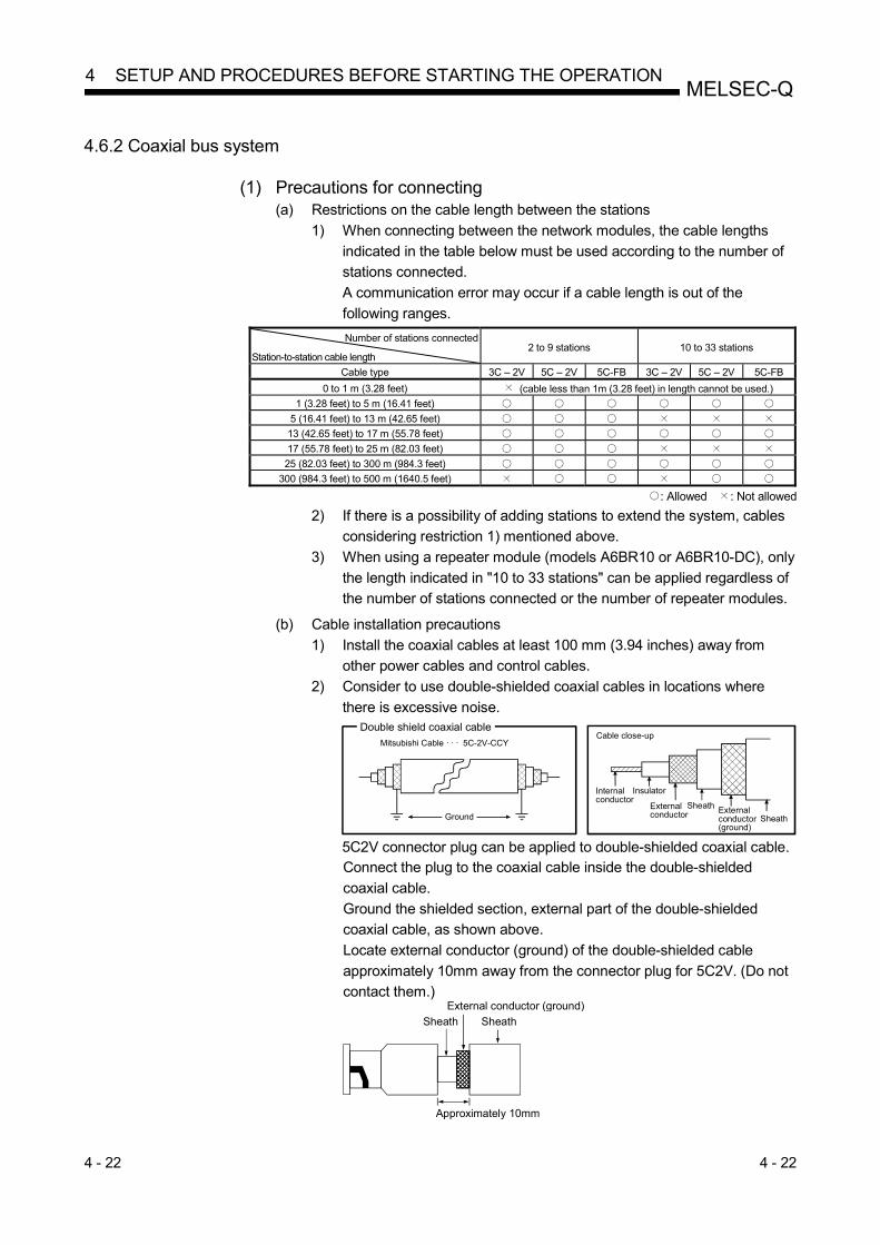
4 - 22 4 - 22
MELSEC-Q 4 SETUP AND PROCEDURES BEFORE STARTING THE OPERATION
4.6.2 Coaxial bus system
(1) Precautions for connecting (a) Restrictions on the cable length between the stations
1) When connecting between the network modules, the cable lengths
indicated in the table below must be used according to the number of
stations connected.
A communication error may occur if a cable length is out of the
following ranges. Number of stations connected
Station-to-station cable length 2 to 9 stations 10 to 33 stations
Cable type 3C – 2V 5C – 2V 5C-FB 3C – 2V 5C – 2V 5C-FB
0 to 1 m (3.28 feet) (cable less than 1m (3.28 feet) in length cannot be used.)
1 (3.28 feet) to 5 m (16.41 feet) 5 (16.41 feet) to 13 m (42.65 feet) 13 (42.65 feet) to 17 m (55.78 feet) 17 (55.78 feet) to 25 m (82.03 feet) 25 (82.03 feet) to 300 m (984.3 feet)
300 (984.3 feet) to 500 m (1640.5 feet)
: Allowed : Not allowed
2) If there is a possibility of adding stations to extend the system, cables
considering restriction 1) mentioned above.
3) When using a repeater module (models A6BR10 or A6BR10-DC), only
the length indicated in "10 to 33 stations" can be applied regardless of
the number of stations connected or the number of repeater modules. (b) Cable installation precautions
1) Install the coaxial cables at least 100 mm (3.94 inches) away from
other power cables and control cables.
2) Consider to use double-shielded coaxial cables in locations where
there is excessive noise.
Ground
Mitsubishi Cable · · · 5C-2V-CCY
Double shield coaxial cable
Internal conductor
Insulator
External conductor
Sheath
Cable close-up
SheathExternal conductor (ground)
5C2V connector plug can be applied to double-shielded coaxial cable. Connect the plug to the coaxial cable inside the double-shielded
coaxial cable.
Ground the shielded section, external part of the double-shielded
coaxial cable, as shown above.
Locate external conductor (ground) of the double-shielded cable
approximately 10mm away from the connector plug for 5C2V. (Do not
contact them.) External conductor (ground)
Approximately 10mm
Sheath Sheath

4 - 23 4 - 23
MELSEC-Q 4 SETUP AND PROCEDURES BEFORE STARTING THE OPERATION
(c) When connecting a coaxial cable, the following restrictions on the bending
radius must be observed.
Cable type Allowable bending radius
r
Connector
A A
r
Front of module
3C – 2V 23 mm (0.91 inches) 55 mm
(2.17 inches) 5C – 2V 30 mm (1.18 inches)
5C – FB 30 mm (1.18 inches)
(d) Do not pull connected coaxial cables.
Doing so may cause poor contact, cable disconnection, and damage to the
module. (e) Connect a terminating resistor to both terminal stations in the coaxial bus
type network system. (f) Depending on a operating environment, some white oxidation deposits may
be seen on the F type connector. Note that oxidation will not occur on the
connection area, so there will be no problems with the function of the unit. (g) Shut off the external power supply for the system in all phases before
connecting or disconnecting coaxial cables.

4 - 24 4 - 24
MELSEC-Q 4 SETUP AND PROCEDURES BEFORE STARTING THE OPERATION
(2) Cable connection
(a) Connection method
Connect the coaxial cable as shown below.
Install a terminating resistor (sold separately: A6RCON-R75) to the stations
connected at both ends.
The F-type connector (A6RCON-F) comes with the module.
1) Without a repeater module
QJ71BR11 QJ71BR11QJ71BR11
Control stationStation No. 1
Normal stationStation No. n
Normal stationStation No. 2
A6RCON-F
Coaxial cable
Terminating resistor A6RCON-R75
(sold separately)
Terminating resistor A6RCON-R75
(sold separately)
n 32
F-type connectorA6RCON-F
F-type connectorA6RCON-F
F-type connector
2) With a repeater module (series connection)
A6BR10
QJ71BR11
Control station
Station No. 1
QJ71BR11
Normal station
Station No. 2
QJ71BR11
Normal station
Station No. 3
QJ71BR11
Normal station
Station No. n
Coaxial cable
T-type
connector
(A6BR10 accessory)
T-type
connector
(A6BR10 accessory)
Coaxial cableTerminating resistor A6RCON-R75
(sold separately)
Terminating resistor A6RCON-R75 (sold separately)
Terminating resistor A6RCON-R75
(sold separately)
n 32
A6RCON-FF-type connector
A6RCON-FF-type connector
A6RCON-FF-type connector
A6RCON-FF-type connector
REMARKS
For details of the repeater module (A6BR10), refer to the following user's manual
attached to the product:
Model A6BR10/A6BR10-DC MELSECNET/10 Coaxial Bus System
Repeater Module User's Manual (IB-66499)
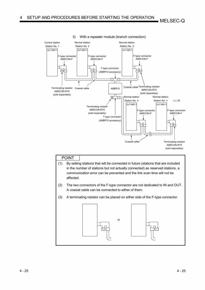
4 - 25 4 - 25
MELSEC-Q 4 SETUP AND PROCEDURES BEFORE STARTING THE OPERATION
3) With a repeater module (branch connection)
QJ71BR11 QJ71BR11 QJ71BR11
QJ71BR11 QJ71BR11
Coaxial cable A6BR10
T-type connector
(A6BR10 accessory)
T-type connector
(A6BR10 accessory)
Terminating resistor A6RCON-R75
(sold separately)
Control station
Station No. 1
Normal station
Station No. 2
Normal station
Station No. 3
Coaxial cable Terminating resistor A6RCON-R75
(sold separately)
Terminating resistor A6RCON-R75
(sold separately)
Normal station
Station No. 4
Normal station
Station No. n
Coaxial cable Terminating resistor A6RCON-R75
(sold separately)
n 32
A6RCON-FF-type connector
A6RCON-FF-type connector
A6RCON-FF-type connector
A6RCON-FF-type connector
A6RCON-FF-type connector
POINT
(1) By setting stations that will be connected in future (stations that are included
in the number of stations but not actually connected) as reserved stations, a
communication error can be prevented and the link scan time will not be
affected.
(2) The two connectors of the F-type connector are not dedicated to IN and OUT.
A coaxial cable can be connected to either of them.
(3) A terminating resistor can be placed on either side of the F-type connector.
or

4 - 26 4 - 26
MELSEC-Q 4 SETUP AND PROCEDURES BEFORE STARTING THE OPERATION
(b) Installing the coaxial cable
The following shows how to install the coaxial cable:
Insert the plug by aligning the groove of the plug with the projection of the jack.
Complete
Start (Installation)
Rotate the plug in the direction of the arrow (clockwise) securely to the position shown in the second figure from above.
Turn OFF the power.
Plug
Jack
Groove
Projection
Network module
(c) Removing the coaxial cable
The following shows how to remove the coaxial cable:
Rotate the plug in the direction of the arrow and unhook it.
Start (Removal)
Complete
Hold the plug by hand and pull it out in the direction of the arrow as shown in the bottom diagram.
Turn OFF the power.
Network modulePlug

4 - 27 4 - 27
MELSEC-Q 4 SETUP AND PROCEDURES BEFORE STARTING THE OPERATION
4.6.3 Twisted bus system (when using a shielded twisted pair cable)
(1) Wiring precautions (a) Wiring a shielded twisted pair cable
When wiring a shielded twisted pair cable, prevent the noise and surge
induction, referring to the following.
1) Do not install a shielded twisted pair cable together with the main
circuit, high-voltage cable, or load line and also do not bring them
close to each other. (Keep a distance of 100mm (3.94 inches) or more
between them.)
2) Provide as much distance as possible between the shielded twisted
pair cables and the power supply of the module or I/O signal cables.
3) Do not use any of shielded twisted pair cables (e.g. One pair among
three pairs) for supplying power.
(b) Connecting terminating resistors
For the network modules at both ends, connect the DA and DB by a
terminating resister (110 , 1/2W) provided with the module.
(c) Connecting/disconnecting a shielded twisted pair cable
Shut off the external power supply for the system in all phases.
(2) Connection of cable
(a) Connection method
For connection between DAs and between DBs, use shielded twisted pair
cables.
No cabling is required for (DG).
In addition, connect terminating resistors for stations at both ends.
DA
DB
(DG)
FG
Shielded twisted pair cable
SLD
DA
DB
(DG)
FG
SLD
DA
DB
(DG)
FG
SLD
DA
DB
(DG)
FG
SLD
Terminatingresistor
(110 , 1/2W)
Terminatingresistor
(110 , 1/2W)

4 - 28 4 - 28
MELSEC-Q 4 SETUP AND PROCEDURES BEFORE STARTING THE OPERATION
(b) Connecting a cable to the spring clamp terminal block
The following explains connecting method of a cable to a spring clamp
terminal block.
For the stripping method of the cable end, refer to Section 3.1.4. in this
manual.
Use a recommended screwdriver or equivalent for connecting or
disconnecting cables. (Refer to Appendix. 5)
1) Connecting the cable
Fully insert the cable into the correct opening with the open/close
button pressed by a slotted screwdriver.
When using a bar terminal, the cable can be inserted without pressing
the button.
Insertion hole
Open/close button
2) Disconnecting the cable
Keep pressing the open/close button by a slotted screwdriver until the
cable is completely pulled out.

4 - 29 4 - 29
MELSEC-Q 4 SETUP AND PROCEDURES BEFORE STARTING THE OPERATION
4.6.4 Twisted bus system (when using CC-Link Ver.1.10-compatible cable)
(1) Wiring precautions (a) Usage of CC-Link cables
The CC-Link Ver. 1.10-compatible cable cannot be used together with other
CC-Link cables (CC-Link dedicated cable and CC-Link dedicated high-
performance cable)
When used together, normal data communication cannot be expected.
(b) Branching of CC-Link cable
Connect network modules only with CC-Link cables.
Repeater hubs and connectors cannot be used.
(c) Grounding of CC-Link cable
Ground both ends of the shielded wire of the CC-Link Ver. 1.10-compatible
cable to the protective ground conductor by connecting to "SLD" of each
network module via "FG".
The SLD and FG are connected within the module.
(d) Connecting a terminating resistor
For the network module at both ends, connect the DA and DB by a
terminating resister (110 , 1/2W) provided with the module.
(e) Connecting/disconnecting CC-Link Ver. 1.10-compatible cable
Shut off the external power supply for the system in all phases.
(2) Connection of cable
(a) Connection method
Connect a blue, white, and yellow cable to the DA, DB, and (DG)
respectively.
In addition, use terminating resistors for the stations at both ends.
DA
DB
(DG)
SLD
FG
DA
DB
FG
SLD
DA
DB
FG
SLD CC-Link Ver.1.10-compatible cable
(DG) (DG)
Terminatingresistor
(110 , 1/2W)
Terminatingresistor
(110 , 1/2W)
(blue)
(White)
(Yellow)
(blue)
(White)
(Yellow)
(blue)
(White)
(Yellow)
(blue)
(White)
(Yellow)
CC-Link Ver.1.10-compatible cable
(b) Wiring to spring clamp terminal block
For the wiring method of a cable to a spring clamp terminal block, refer to
Section 4.6.3 (2) (b) in this manual.

4 - 30 4 - 30
MELSEC-Q 4 SETUP AND PROCEDURES BEFORE STARTING THE OPERATION
4.7 Offline Tests from GX Developer
The offline tests check the cable connection status using the network parameters of
GX Developer.
4.7.1 Station-to-station test
In the station-to-station test, the hardware of the network modules and cables between
two adjacent stations can be checked.
The following explains how to conduct the station-to-station test:
(1) System configurations
(a) [Optical loop system]
Connect IN and OUT of two network modules with an optical fiber cable.
Side
Station No. n
Optical fiber cable
Station to execute test
IN
OUT
Station to be tested
Side
Station No. n+1
IN
OUT
(b) [Coaxial bus system]
Connect two network modules with a coaxial cable.
Terminatingresistor
Coaxial cable
Side
Station No. n
Station to be tested
Side
Station No. n+1
Station to execute test
Terminatingresistor
(c) [Twisted bus system]
Connect the network module with a shielded twisted pair cable or CC-Link
Ver. 1.10-compatible cable.
Twisted pair cable or CC-Link Ver. 1.10- compatible cable
Station to execute test
front
Station to be tested
front
Terminating resistor
Terminatingresistor
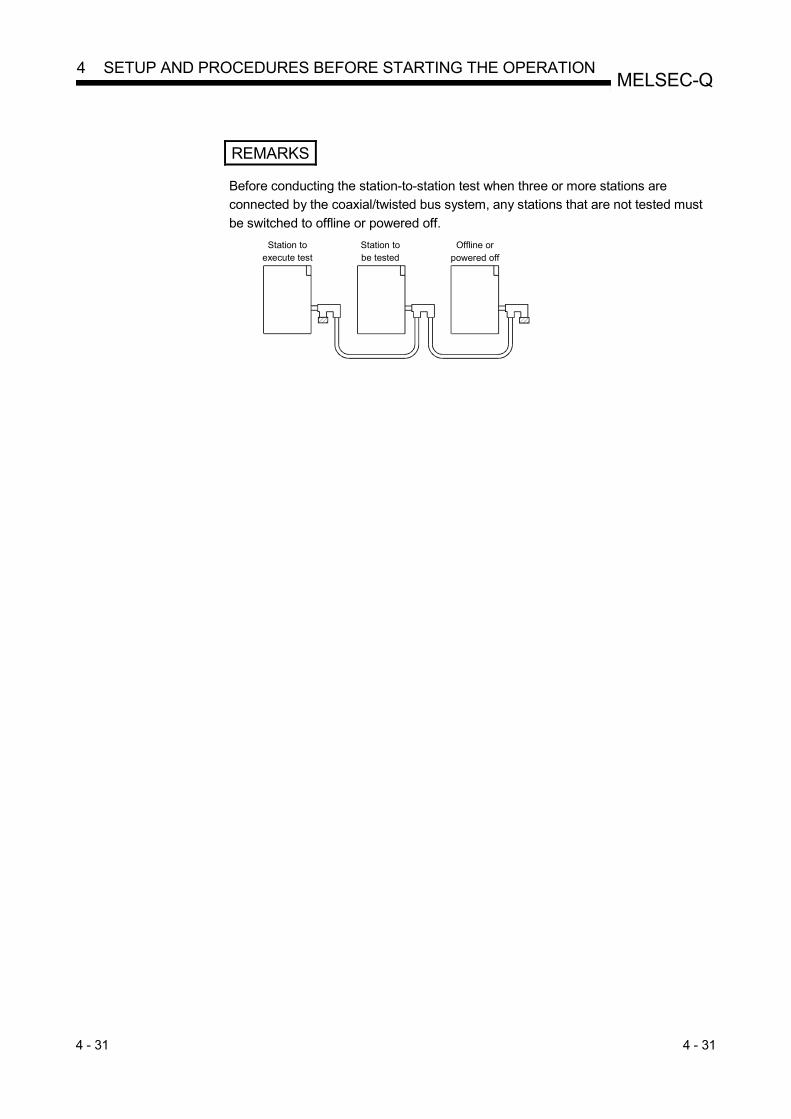
4 - 31 4 - 31
MELSEC-Q 4 SETUP AND PROCEDURES BEFORE STARTING THE OPERATION
REMARKS
Before conducting the station-to-station test when three or more stations are
connected by the coaxial/twisted bus system, any stations that are not tested must
be switched to offline or powered off.
Offline or powered off
Station to be tested
Station to execute test

4 - 32 4 - 32
MELSEC-Q 4 SETUP AND PROCEDURES BEFORE STARTING THE OPERATION
(2) Setting the test mode
(a) Mode setting for the station-to-station test on a non-redundant system station Set the mode network parameters for station number n and station number n + 1 to "Test between master station" and "Test between slave station" respectively, and write the parameter settings to the CPU module.
Station to execute test (station No. n) Station to be tested (station No. n + 1)
Set Set
(b) Mode setting for the station-to-station test in the redundant system To perform the station-to-station test in the redundant system, set the operation mode of the redundant CPU to backup mode. If the power to both systems cannot be turned on or off, perform the station-to-station test in separate mode. The table below shows the mode settings available for the station-to-station test in the redundant system.
Set station Description of setting
Station performing the test
In backup mode Set "Test between master station" or "Test between slave station." In separate mode
Station not performing the test
In backup mode Set "Offline."
In separate mode Set "Online."
The following shows a case where a non-redundant system (station No. 1) is set as a testing station and system A (station No. 2) of the redundant system (in backup mode) is set as a tested station.
Po
wer
su
pply
mod
ule
Q25HCPU
StationNo. 1
Standby system(system B)
Control system(system A)
RedundantCPU
StationNo. 2
Pow
er
sup
ply
mo
dule
RedundantCPU
StationNo. 3
Pow
er
sup
ply
mo
dule
Set "Test between slave station"
for the mode of system A (station No. 2).
Set "Test between master station"
for the mode of station No. 1.
Set "Offline" for the mode of system B (station No. 3).
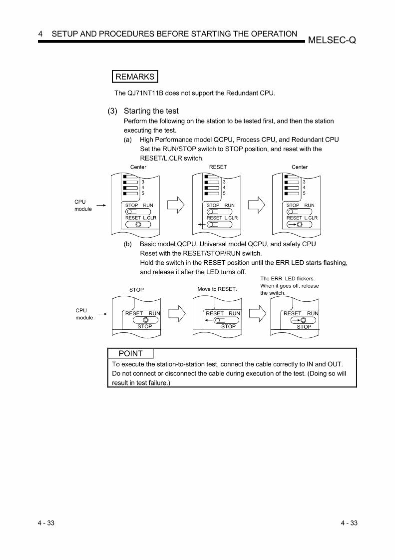
4 - 33 4 - 33
MELSEC-Q 4 SETUP AND PROCEDURES BEFORE STARTING THE OPERATION
REMARKS
The QJ71NT11B does not support the Redundant CPU.
(3) Starting the test
Perform the following on the station to be tested first, and then the station
executing the test.
(a) High Performance model QCPU, Process CPU, and Redundant CPU
Set the RUN/STOP switch to STOP position, and reset with the
RESET/L.CLR switch.
345
STOP RUN
RESET L.CLR
345
STOP RUN
RESET L.CLR
345
STOP RUN
RESET L.CLR
Center RESET Center
CPU module
(b) Basic model QCPU, Universal model QCPU, and safety CPU
Reset with the RESET/STOP/RUN switch.
Hold the switch in the RESET position until the ERR LED starts flashing,
and release it after the LED turns off.
STOP
RUNRESET
Move to RESET.
CPUmodule
STOP
RUNRESET
STOP
RUNRESET
STOP
The ERR. LED flickers. When it goes off, releasethe switch.
POINT
To execute the station-to-station test, connect the cable correctly to IN and OUT.
Do not connect or disconnect the cable during execution of the test. (Doing so will
result in test failure.)

4 - 34 4 - 34
MELSEC-Q 4 SETUP AND PROCEDURES BEFORE STARTING THE OPERATION
(4) Checking the test result
The T.PASS LED of the network module flashes at approximately 0.5 s intervals. When the T. PASS LED flashes 20 times (approx. 10 seconds) 1 or more and if the ERR.LED does not flash, this condition indicates normal completion. When the test has failed, the ERR. LED flashes. [Normal test result]
RUN MNG
T.PASS D.LINK
SD RD
ERR. L ERR.
MNG
D.LINK
RD
L ERR.
Switch position
Display section
Before test (during RESET)
During test (during STOP)
Test complete
Complete when T.PASS flashed 20 times (approx. 10 seconds) or more.
RUN
T.PASS
SD
ERR.
Or L. ERR. 1
[Abnormal test result]
RUN MNG
T.PASS D.LINK
SD RD
ERR. L ERR.
MNG
D.LINK
RD
L ERR.
Switch position
Display section
Before test (during RESET)
During test (during STOP)
Test complete
Flashing of the ERR. LED indicates an error.
Or L. ERR.
RUN
T.PASS
SD
ERR.
Upon detection of an error, the test will be terminated (abnormal termination).
1: For the twisted bus system, the test is conducted at 156kbps and eight
minutes is required for the test.
If the ERR. LED does not flash after the eight minutes, the test has
completed normally. (a) Possible causes of errors in the optical loop system
1) Forward loop error
• The cable of the forward loop is disconnected.
• The sending and receiving stations of the forward loop are not
connected with a cable.
• The sending stations of the forward and reverse loops, or the
receiving stations of the forward and reverse loops are connected. 2) Reverse loop error
• The cable of the reverse loop is disconnected.
• The sending and receiving stations of the reverse loop are not
connected with a cable. 3) Defective cable 4) The cable was disconnected or broken during the test 5) Hardware error
(b) Possible causes of errors in the coaxial/twisted bus system 1) The cable is broken or defective 2) The cable was disconnected or broken during the test 3) A terminating resistor was detached 4) Hardware error 5) Incorrect wiring (For the twisted bus system)

4 - 35 4 - 35
MELSEC-Q 4 SETUP AND PROCEDURES BEFORE STARTING THE OPERATION
REMARKS
Testing status and the result can be checked in the following link special registers. Baton pass status (host) SW0047 1FH : Offline test Cause of baton pass interruption SW0048 2H : Offline test Offline test execution item/faulty station (requesting side)
SW00AC 5H or 6H : Station-to-station test
Offline test result (requesting side) SW00AD 0 : Normal 1 or larger : Error code For details of how to check the error contents, refer to Chapter 8.
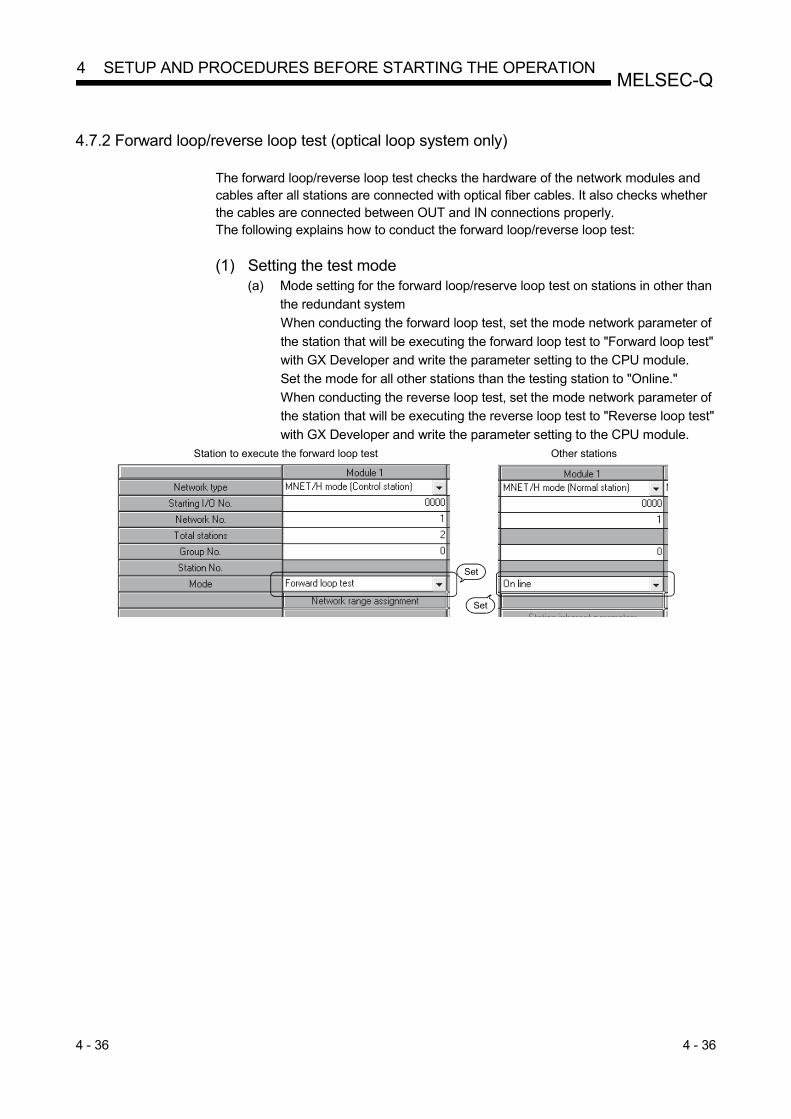
4 - 36 4 - 36
MELSEC-Q 4 SETUP AND PROCEDURES BEFORE STARTING THE OPERATION
4.7.2 Forward loop/reverse loop test (optical loop system only)
The forward loop/reverse loop test checks the hardware of the network modules and cables after all stations are connected with optical fiber cables. It also checks whether the cables are connected between OUT and IN connections properly. The following explains how to conduct the forward loop/reverse loop test:
(1) Setting the test mode
(a) Mode setting for the forward loop/reserve loop test on stations in other than
the redundant system
When conducting the forward loop test, set the mode network parameter of
the station that will be executing the forward loop test to "Forward loop test"
with GX Developer and write the parameter setting to the CPU module.
Set the mode for all other stations than the testing station to "Online."
When conducting the reverse loop test, set the mode network parameter of
the station that will be executing the reverse loop test to "Reverse loop test"
with GX Developer and write the parameter setting to the CPU module. Station to execute the forward loop test Other stations
Set
Set
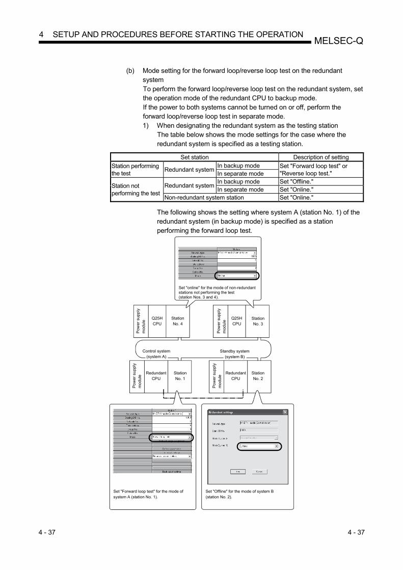
4 - 37 4 - 37
MELSEC-Q 4 SETUP AND PROCEDURES BEFORE STARTING THE OPERATION
(b) Mode setting for the forward loop/reverse loop test on the redundant
system To perform the forward loop/reverse loop test on the redundant system, set the operation mode of the redundant CPU to backup mode. If the power to both systems cannot be turned on or off, perform the forward loop/reverse loop test in separate mode. 1) When designating the redundant system as the testing station
The table below shows the mode settings for the case where the redundant system is specified as a testing station.
Set station Description of setting
Station performing the test
Redundant system In backup mode Set "Forward loop test" or
"Reverse loop test." In separate mode
Station not performing the test
Redundant system In backup mode Set "Offline." In separate mode Set "Online."
Non-redundant system station Set "Online."
The following shows the setting where system A (station No. 1) of the redundant system (in backup mode) is specified as a station performing the forward loop test.
RedundantCPU
RedundantCPU
Pow
er s
uppl
ym
odul
e
Q25HCPU
StationNo. 4
Q25HCPU
Control system(system A)
Standby system (system B)
Set "Offline" for the mode of system B (station No. 2).
Set "Forward loop test" for the mode of system A (station No. 1).
Set "online" for the mode of non-redundantstations not performing the test (station Nos. 3 and 4).
Pow
er s
uppl
ym
odul
e
StationNo. 3
Po
wer
sup
ply
mo
dule
Po
wer
sup
ply
mo
dule
StationNo. 2
StationNo. 1

4 - 38 4 - 38
MELSEC-Q 4 SETUP AND PROCEDURES BEFORE STARTING THE OPERATION
2) When designating a station in other than the redundant system as a
testing station
The settings are the same as those for the usual forward loop/reverse
loop test (refer to (1) (a) of this section).
Set "Online" to the redundant system modes of both systems A and B.
Set "Online" for the mode of both systems A and B.
<Settings for system A> <Settings for system B>
(2) Starting the test
Perform the following on the station to be tested first, and then the station executing the test. (a) High Performance model QCPU, Process CPU, and Redundant CPU
Set the RUN/STOP switch to STOP position, and reset with the
RESET/L.CLR switch.
345
STOP RUN
RESET L.CLR
345
STOP RUN
RESET L.CLR
345
STOP RUN
RESET L.CLR
Center RESET Center
CPUmodule
(b) Basic model QCPU, Universal model QCPU, and Safety CPU
Reset with the RESET/STOP/RUN switch.
Hold the switch in the RESET position until the ERR. LED starts flashing,
and release it after the LED turns off.
STOP
RUNRESET
Move to RESET.
CPUmodule
STOP
RUNRESET
STOP
RUNRESET
STOP
The ERR. LED flickers. When it goes off, releasethe switch.
POINT
To execute the forward loop/reverse loop test, connect the cable correctly to IN and
OUT. Do not connect or disconnect the cable during execution of the test. (Doing
so will result in test failure.)
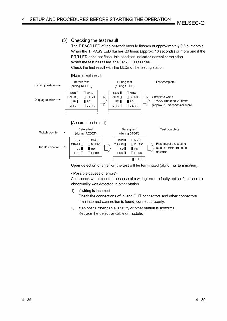
4 - 39 4 - 39
MELSEC-Q 4 SETUP AND PROCEDURES BEFORE STARTING THE OPERATION
(3) Checking the test result
The T.PASS LED of the network module flashes at approximately 0.5 s intervals.
When the T. PASS LED flashes 20 times (approx. 10 seconds) or more and if the
ERR.LED does not flash, this condition indicates normal completion.
When the test has failed, the ERR. LED flashes.
Check the test result with the LEDs of the testing station.
[Normal test result]
RUN MNG
T.PASS D.LINK
SD RD
ERR. L ERR.
MNG
D.LINK
RD
L ERR.
Switch position
Display section
Before test (during RESET)
During test (during STOP)
Test complete
Complete when T.PASS flashed 20 times (approx. 10 seconds) or more.
RUN
T.PASS
SD
ERR.
[Abnormal test result]
RUN MNG
T.PASS D.LINK
SD RD
ERR. L ERR.
MNG
D.LINK
RD
L ERR.
Switch position
Display section
Before test (during RESET)
During test (during STOP)
Test complete
Flashing of the testingstation's ERR. Indicatesan error.
Or L. ERR.
RUN
T.PASS
SD
ERR.
Upon detection of an error, the test will be terminated (abnormal termination).
<Possible causes of errors>
A loopback was executed because of a wiring error, a faulty optical fiber cable or
abnormality was detected in other station. 1) If wiring is incorrect
Check the connections of IN and OUT connectors and other connectors.
If an incorrect connection is found, connect properly. 2) If an optical fiber cable is faulty or other station is abnormal
Replace the defective cable or module.

4 - 40 4 - 40
MELSEC-Q 4 SETUP AND PROCEDURES BEFORE STARTING THE OPERATION
REMARKS
Testing status and the result can be checked in the following link special registers. Baton pass status (host) SW0047 1FH : Offline test Cause of baton pass interruption SW0048 2H : Offline test Offline test execution item/faulty station (requesting side)
SW00AC 03H
or 04H
: Loop test
Offline test result (requesting side) SW00AD 0 : Normal 1 or larger : Error code For details of how to check the error contents, refer to Chapter 8.
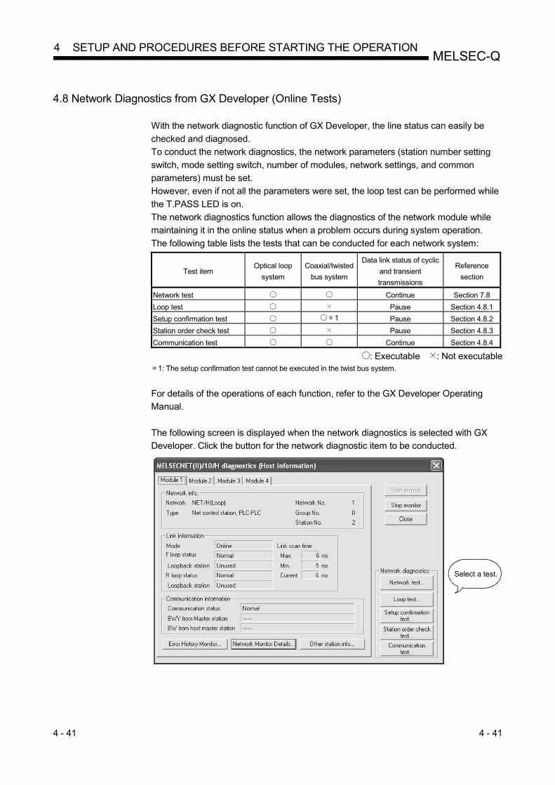
4 - 41 4 - 41
MELSEC-Q 4 SETUP AND PROCEDURES BEFORE STARTING THE OPERATION
4.8 Network Diagnostics from GX Developer (Online Tests)
With the network diagnostic function of GX Developer, the line status can easily be
checked and diagnosed.
To conduct the network diagnostics, the network parameters (station number setting
switch, mode setting switch, number of modules, network settings, and common
parameters) must be set.
However, even if not all the parameters were set, the loop test can be performed while
the T.PASS LED is on.
The network diagnostics function allows the diagnostics of the network module while
maintaining it in the online status when a problem occurs during system operation.
The following table lists the tests that can be conducted for each network system:
Test item Optical loop
system
Coaxial/twisted
bus system
Data link status of cyclic
and transient
transmissions
Reference
section
Network test Continue Section 7.8
Loop test Pause Section 4.8.1
Setup confirmation test 1 Pause Section 4.8.2
Station order check test Pause Section 4.8.3
Communication test Continue Section 4.8.4
: Executable : Not executable 1: The setup confirmation test cannot be executed in the twist bus system.
For details of the operations of each function, refer to the GX Developer Operating
Manual.
The following screen is displayed when the network diagnostics is selected with GX
Developer. Click the button for the network diagnostic item to be conducted.
Select a test.

4 - 42 4 - 42
MELSEC-Q 4 SETUP AND PROCEDURES BEFORE STARTING THE OPERATION
4.8.1 Loop test (optical loop system only)
This test checks the line status of the forward and reverse loops upon completion of
the wiring of the optical loop system. Also, when a loopback is being executed, it
checks the station that executes the loopback.
For example, in the system shown below, where the IN/OUT connectors of station
number 5 are connected in reverse, conduct a loop test using GX Developer
connected to station number 1.
The monitor screen shown below appears after the loop test has been executed, and
station No. 5 is detected as the station with a receiving direction error.
GX Developer
StationNo. 1
Reserved station Loopback
Faulty station
IN OUT
Loopback
StationNo. 3IN OUT
StationNo. 6IN OUT
StationNo. 4IN OUT
INOUTStationNo. 8
INOUTStationNo. 7
INOUTStationNo. 2
IN OUTStationNo. 5
POINT
In the loop test, data link is stopped to check the wiring status.
To check the wiring status without stopping data link, check the status of SW009C
to 009F.
Refer to Section 8.2.10 for details.

4 - 43 4 - 43
MELSEC-Q 4 SETUP AND PROCEDURES BEFORE STARTING THE OPERATION
4.8.2 Setup confirmation test (optical loop, coaxial bus system only)
The switch settings of the network module can be checked with this test.
The following three types of items can be checked:
1) Control station duplication check
2) Station number duplication check
3) Matching between the network number set for the station to which GX
Developer is connected and the network number set with a network
parameter of the host
For example, in the following system, when the Setup confirmation test is conducted
by GX Developer connected to station number 1, the monitor screen shown below is
displayed and the setting status of each station can be checked.
Station number 6 displays a duplicate control station setting error, and station numbers
2, 5, 7, and 8 display the network numbers and group numbers because there are no
setting errors.
(Parameter settings)
Control station Group No. 1 Reserved station Reserved station
Group No. 2Control stationGroup No. 1Group No. 2
Network No. 1
Duplicate error
GX DeveloperStationNo. 1
IN OUT
StationNo. 2
IN OUT
StationNo. 3
IN OUT
StationNo. 4
IN OUT
StationNo. 8
OUT INStationNo. 7
OUT INStationNo. 6
OUT INStationNo. 5
OUT IN
POINT
The setup confirmation test cannot be executed in the twist bus system.

4 - 44 4 - 44
MELSEC-Q 4 SETUP AND PROCEDURES BEFORE STARTING THE OPERATION
4.8.3 Station order check test (optical loop system only)
This test checks the connected station numbers in the optical loop system.
The following connection orders can be checked by the loop status (displayed on the
station order check test result screen. Refer to the monitor screen below.) when this
test is conducted. Loop status Display
Forward and reverse loops The station numbers connected in the direction of the forward loop from the host as well as
the station numbers connected to the direction of the reverse loop from the host
Forward loop Only the station numbers connected in the direction of the forward loop from the host
Reverse loop Only the station numbers connected in the direction of the reverse loop from the host
Loop back Only the station numbers connected in the direction of the forward loop from the host
For example, in the following system, when the station order check test is conducted
by GX Developer connected to station number 1, the monitor screen shown below is
displayed to verify that a loopback is being executed between station numbers 4 and 2
that are connected in the direction of the forward loop.
Forward loop direction
Reverse loop direction
StationNo. 1
Reserved station Loopback
IN OUT
StationNo. 3IN OUT
StationNo. 6IN OUT
StationNo. 4IN OUT
Faulty stationLoopback
INOUTStationNo. 8
INOUTStationNo. 7
INOUTStationNo. 2
INOUTStationNo. 5
GX Developer
Station No. 3 is not displayed because it is a reserved station.

4 - 45 4 - 45
MELSEC-Q 4 SETUP AND PROCEDURES BEFORE STARTING THE OPERATION
4.8.4 Communication test
This test checks whether or not data communication can normally be performed
between the host and a destination station (specified with network number and station
number). Especially when the destination has another network number, the relay
network and station numbers are displayed. So, make sure that the routing parameters
are properly set.
In the following system, when the communication test is conducted to 4Ns6 of network
number 4 by GX Developer connected to 1Ns1 of network number 1, the monitor
screen shown below is displayed to verify that normal communication can be
performed with the contents of the routing parameter settings.
Host
1NS1 1NS2
Network No. 1
1NS4 1NS3
2NS1 2NS3
Network No. 2
2NS6 2NS4
1MP5 2MP2 2NS5 3MP1
3NS3
3NS5 3NS4
3NS2 4NS5
4MP1 4NS2
Network No. 4
4NS6 4NS4
Destination
Network No. 3
4NS3
GX Developer
Forward path from the host to the destination
Return path from the destination to the host
Station numbers of relay stations5 is the station No. of network No. 1 side2 is the station No. of network No. 2 side
REMARKS
If the routing parameters are not properly set, the message "Cannot communicate
with PLC" is displayed and the communication result is not displayed.

5 - 1 5 - 1
MELSEC-Q 5 PARAMETER SETTINGS
5 PARAMETER SETTINGS
To run the MELSECNET/H, the parameters for the network module mounted to the programmable controller CPU must be set with GX Developer. Depending on the network configuration, some parameters must be set, some must be set as required, and some do not. The following pages provide lists of parameter settings required for each network configuration.
Construct a single network system?
Yes
Yes
See parameter list (4)shown in this chapter.
No
No Construct aredundant system?
Yes
Construct multiplenetwork systems?
Yes
No
Construct multiplenetwork systems?
Yes
No (Construct a simplified redundant system.)Construct multiplenetwork systems?
See parameter list (1)shown in this chapter.
See parameter list (4) shown in this chapter.
See parameter list (2) shown in this chapter.
See parameter list (4)shown in this chapter.
See parameter list (3)shown in this chapter.
No
Start parameter settings.
5

5 - 2 5 - 2
MELSEC-Q 5 PARAMETER SETTINGS
(1) List of parameter settings for a single network system
Parameter setting item Necessity for setting by station type
Reference section Control station Normal station
Network type
(MNET/H mode
(control station), MNET/H
EX (control station))
(MNET/H mode
(normal station), MNET/H
EX (normal station))
Section 5.1
Starting I/O No. Section 5.2.1
Network No. Section 5.2.2
Total stations Section 5.2.3
Group No. Sections 5.2.4 and 7.4.3
Mode Section 5.2.5
Communication speed setting Section 5.2.6
Network range
assignment
(common parameters)
Monitoring time Section 5.4
LB/LW
settings
Send range of each station
(LB/LW) Section 5.3.1
Send range of each station
(low-speed LB/LW) Section 7.3
Pairing setting Section 7.10.3
LX/LY settings Section 5.3.2
I/O master station specification Section 5.3.3
Reserved station specification Section 5.3.4
Supplement
ary settings
Constant link scan Section 5.4
Maximum No. of returns to system
stations in 1 scan. Section 5.4
Multiplex transmission
specification Section 5.4
Control station shift setting Section 5.4
Block send data assurance per
station 1 Section 5.4
Block receive data assurance per
station 1 Section 5.4
Transient setting Section 5.4
Low-speed cyclic transmission
specification Section 5.4
Station specific parameters Section 5.6
Refresh parameters 2 3 2 3 Section 5.7
Interrupt settings Section 7.5.1
Control station return setting Section 5.5
Standby station compatible module Section 5.9
Redundant settings Section 7.10.4
Interlink transmission parameters Section 7.2
Routing parameters Section 7.4.2
Valid module during other station access Section 5.8
1: In the MELSECNET/H Extended mode, the default check mark is displayed.
2: Default values are not set for LX/LY. Set refresh parameters.
3: Default values are preset for LB/LW.
Any CPU other than Universal model QCPU may operate even if refresh parameters have not been set.
For the operation and precautions, refer to Section 5.7.2 (3).
: Set at all times (no default setting).
: Set at all times (default setting provided).
: Set as appropriate.
: Setting unnecessary.
5

5 - 3 5 - 3
MELSEC-Q 5 PARAMETER SETTINGS
(2) List of parameter settings for a redundant system
Parameter setting item Necessity for setting by station type
Reference section Control station Normal station
Network type
(MNET/H mode
(control station), MNET/H
EX (control station))
(MNET/H mode
(normal station), MNET/H
EX (normal station))
Section 5.1
Starting I/O No. Section 5.2.1
Network No. Section 5.2.2
Total stations Section 5.2.3
Group No. Sections 5.2.4 and 7.4.3
Mode Section 5.2.5
Communication speed setting Section 5.2.6
Network range
assignment
(common parameters)
Monitoring time Section 5.4
LB/LW
settings
Send range of each station
(LB/LW) Section 5.3.1
Send range of each station
(low-speed LB/LW) Section 7.3
Pairing setting Section 7.10.3
LX/LY settings Section 5.3.2
I/O master station specification Section 5.3.3
Reserved station specification Section 5.3.4
Supplement
ary settings
Constant link scan Section 5.4
Maximum No. of returns to system
stations in 1 scan. Section 5.4
Multiplex transmission
specification Section 5.4
Control station shift setting Section 5.4
Block send data assurance per
station Section 5.4
Block receive data assurance per
station Section 5.4
Transient setting Section 5.4
Low-speed cyclic transmission
specification Section 5.4
Station inherent parameters Section 5.6
Refresh parameters 2 3 2 3 Section 5.7
Interrupt settings Section 7.5.1
Control station return setting Section 5.5
Standby station compatible module Section 5.9
Redundant settings 1 1 Section 7.10.4
Interlink transmission parameters Section 7.2
Routing parameters Section 7.4.2
Valid module during other station access Section 5.8
1: This setting is necessary when the CPU module installed with a network module is a Redundant CPU.
2: Default values are not set for LX/LY. Set refresh parameters.
3: Default values are preset for LB/LW.
The system may operate even if refresh parameters have not been set.
For the operation and precautions, refer to Section 5.7.2 (3).
: Set at all times (no default setting).
: Set at all times (default setting provided).
: Set as appropriate.
: Setting unnecessary.

5 - 4 5 - 4
MELSEC-Q 5 PARAMETER SETTINGS
(3) List of parameter settings for a simplified redundant system
Parameter setting item Necessity for setting by station type
Reference section Control station Normal station Standby station
Network type
(MNET/H
mode (control
station), MNET/H
EX (control
station))
(MNET/H
mode (normal
station), MNET/H
EX (normal
station))
(MNET/H
standby station) Section 5.1
Starting I/O No. Section 5.2.1
Network No. Section 5.2.2
Total stations Section 5.2.3
Group No. Sections 5.2.4 and
7.4.3
Mode Section 5.2.5
Communication speed setting Section 5.2.6
Network range
assignment
(common parameters)
Monitoring time Section 5.4
LB/LW
settings
Send range of each station
(LB/LW) Section 5.3.1
Send range of each station
(low-speed LB/LW) Section 7.3
Pairing setting Section 7.10.3
LX/LY settings Section 5.3.2
I/O master station specification Section 5.3.3
Reserved station specification Section 5.3.4
Supplement
ary settings
Constant link scan Section 5.4
Maximum No. of returns to system
stations in 1 scan. Section 5.4
Multiplex transmission
specification Section 5.4
Control station shift setting Section 5.4
Block send data assurance per
station 1 Section 5.4
Block receive data assurance per
station 1 Section 5.4
Transient setting Section 5.4
Low-speed cyclic transmission
specification Section 5.4
Station inherent parameters Section 5.6
Refresh parameters 2 3 2 3 Section 5.7
Interrupt settings Section 7.5.1
Control station return setting Section 5.5
Standby station compatible module Section 5.9
Redundant settings Section 7.10.4
Interlink transmission parameters Section 7.2
Routing parameters Section 7.4.2
Valid module during other station access Section 5.8
1: In the MELSECNET/H Extended mode, the default check mark is displayed.
2: Default value is not set in LX/LY. Set refresh parameters.
3: Default values are preset for LB/LW.
The system may operate even if refresh parameters have not been set.
For the operation and precautions, refer to Section 5.7.2 (3).
: Set at all times (no default setting).
: Set at all times (default setting provided).
: Set as appropriate.
: Setting unnecessary.

5 - 5 5 - 5
MELSEC-Q 5 PARAMETER SETTINGS
(4) List of parameter settings for multiple network systems
Parameter setting item Necessity for setting by station type
Reference section Control station Normal station Standby station 1
Network type
(MNET/H
mode (control
station), MNET/H
EX (control
station))
(MNET/H
mode (normal
station), MNET/H
EX (normal
station))
(MNET/H
standby station) Section 5.1
Starting I/O No. Section 5.2.1
Network No. Section 5.2.2
Total stations Section 5.2.3
Group No. Sections 5.2.4 and
7.4.3
Mode Section 5.2.5
Communication speed setting Section 5.2.6
Network range
assignment
(common parameters)
Monitoring time Section 5.4
LB/LW
settings
Send range of each station
(LB/LW) Section 5.3.1
Send range of each station
(low-speed LB/LW) Section 7.3
Pairing setting 2 Section 7.10.3
LX/LY settings Section 5.3.2
I/O master station specification Section 5.3.3
Reserved station specification Section 5.3.4
Supplement
ary settings
Constant link scan Section 5.4
Maximum No. of returns to system
stations in 1 scan. Section 5.4
Multiplex transmission setting Section 5.4
Control station shift designation Section 5.4
Block send data assurance per
station 3 Section 5.4
Block receive data assurance per
station 3 Section 5.4
Transient setting Section 5.4
Low-speed cyclic transmission
specification Section 5.4
Station inherent parameters Section 5.6
Refresh parameters 4 5 4 5 Section 5.7
Interrupt settings Section 7.5.1
Control station return setting Section 5.5
Standby station compatible module Section 5.9
Redundant settings 6 6 Section 7.10.4
Interlink transmission parameters Section 7.2
Routing parameters Section 7.4.2
Valid module during other station access Section 5.8
1: This setting is necessary to configure multiple networks using a simplified redundant system.
2: This setting is necessary to configure multiple networks using a redundant system.
3: In the MELSECNET/H Extended mode, the default check mark is displayed.
4: Default value is not set in LX/LY. Set refresh parameters.
5: Default values are preset for LB/LW.
Any CPU other than Universal model QCPU may operate even if refresh parameters have not been set.
For the operation and precautions, refer to Section 5.7.2 (3).
6: This setting is necessary when the CPU module installed with a network module is a Redundant CPU.
: Set at all times (no default setting).
: Set at all times (default setting provided).
: Set as appropriate.
: Setting unnecessary.
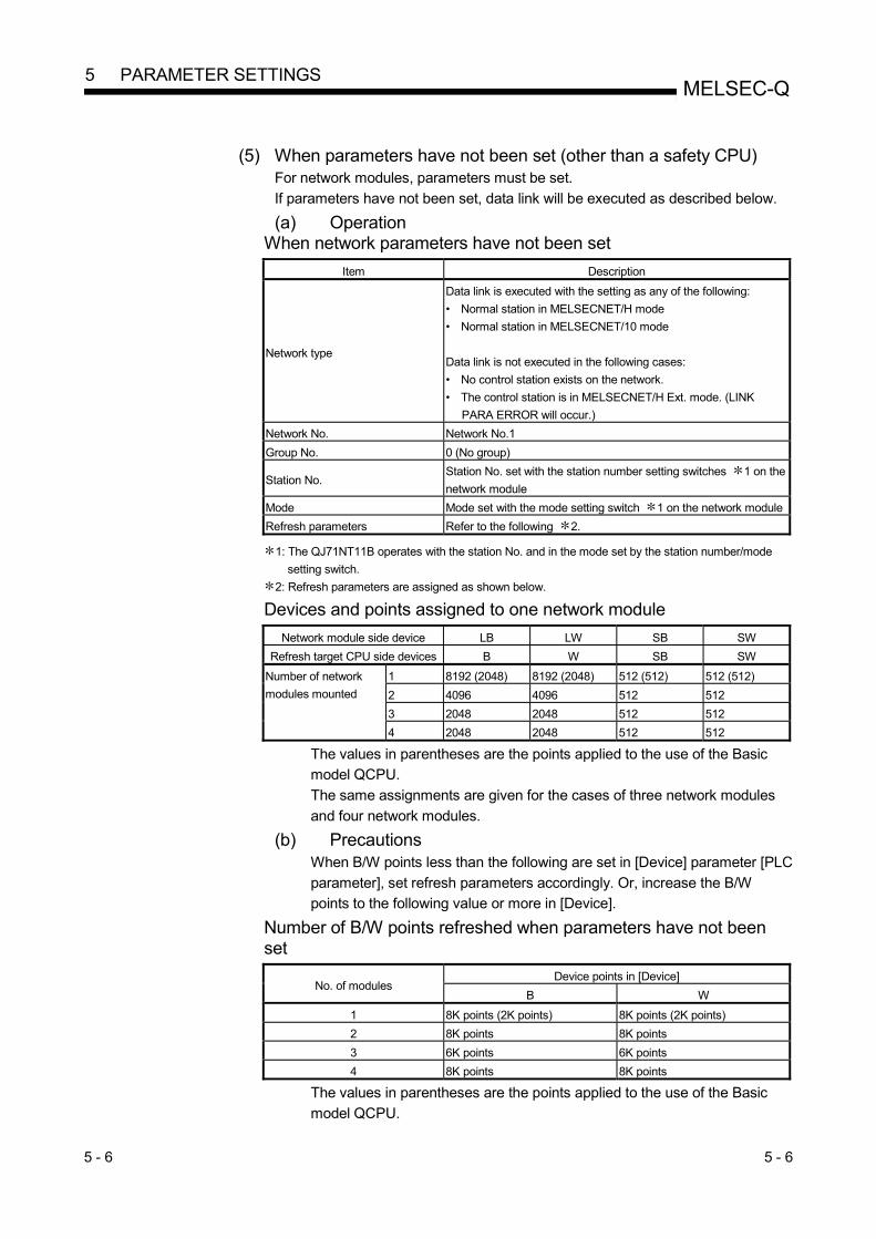
5 - 6 5 - 6
MELSEC-Q 5 PARAMETER SETTINGS
(5) When parameters have not been set (other than a safety CPU)
For network modules, parameters must be set.
If parameters have not been set, data link will be executed as described below. (a) Operation
When network parameters have not been set
Item Description
Network type
Data link is executed with the setting as any of the following:
• Normal station in MELSECNET/H mode
• Normal station in MELSECNET/10 mode
Data link is not executed in the following cases:
• No control station exists on the network.
• The control station is in MELSECNET/H Ext. mode. (LINK
PARA ERROR will occur.)
Network No. Network No.1
Group No. 0 (No group)
Station No. Station No. set with the station number setting switches 1 on the
network module
Mode Mode set with the mode setting switch 1 on the network module
Refresh parameters Refer to the following 2.
1: The QJ71NT11B operates with the station No. and in the mode set by the station number/mode
setting switch.
2: Refresh parameters are assigned as shown below. Devices and points assigned to one network module
Network module side device LB LW SB SW
Refresh target CPU side devices B W SB SW
Number of network
modules mounted
1 8192 (2048) 8192 (2048) 512 (512) 512 (512)
2 4096 4096 512 512
3 2048 2048 512 512
4 2048 2048 512 512
The values in parentheses are the points applied to the use of the Basic
model QCPU.
The same assignments are given for the cases of three network modules
and four network modules. (b) Precautions
When B/W points less than the following are set in [Device] parameter [PLC
parameter], set refresh parameters accordingly. Or, increase the B/W
points to the following value or more in [Device]. Number of B/W points refreshed when parameters have not been set
No. of modules Device points in [Device]
B W
1 8K points (2K points) 8K points (2K points)
2 8K points 8K points
3 6K points 6K points
4 8K points 8K points
The values in parentheses are the points applied to the use of the Basic
model QCPU.

5 - 7 5 - 7
MELSEC-Q 5 PARAMETER SETTINGS
5.1 Setting the Number of Modules (Network Type)
Set the network type and the station type for each module.
Up to four modules can be set for a combination of MELSECNET/H and CC-Link IE
Controller Network.
Note that, however, there are restrictions on the number of modules mounted for one
programmable controller CPU depending on the CPU model used. (Refer to the user's
manual for the CPU module used.)
For the MELSECNET/H network system, select control station, normal station, or
standby station.
(1) Selection type Select from the following items:
Item Description
MNET/H mode (Control station) Set this item for a control station of the MELSECNET/H mode.
MNET/H mode (Normal station) Set this item for a normal station of the MELSECNET/H mode.
MNET/10 mode (Control station)
1 Set this item for a control station of the MELSECNET/10 mode.
MNET/10 mode (Normal station)
1 Set this item for a normal station of the MELSECNET/10 mode.
MNET/H mode Stand by station Set this item for a standby station of a simplified redundant
system.
MNET/H EX (Control station) Set this item for a control station of the MELSECNET/H
Extended mode.
MNET/H EX (Normal station) Set this item for a normal station of the MELSECNET/H
Extended mode.
1: The QJ71NT11B does not support MESECNE/10 mode.

5 - 8 5 - 8
MELSEC-Q 5 PARAMETER SETTINGS
(2) Precautions
(a) Network type within the same network
Set all network modules within the same network to the same network type.
If there are different network types within the same network, some of the
network modules may be disconnected from the system, for example, and
normal data link is not executed.
Refer to Section 8.2.11 for details. (b) When the MELSECNET/H Extended mode is set
When using MELSECNET/H Extended mode, use the compatible network
module and GX Developer.
For the compatible versions of the module, refer to Section 2.2.
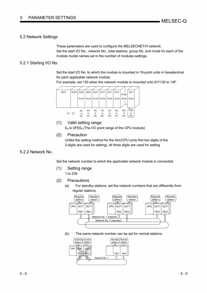
5 - 9 5 - 9
MELSEC-Q 5 PARAMETER SETTINGS
5.2 Network Settings
These parameters are used to configure the MELSECNET/H network.
Set the start I/O No., network No., total stations, group No. and mode for each of the
module model names set in the number of modules settings. 5.2.1 Starting I/O No.
Set the start I/O No. to which the module is mounted in 16-point units in hexadecimal
for each applicable network module.
For example, set 130 when the network module is mounted onto X/Y130 to 14F.
Q61P QCPU QX42 QX42 QX41 QY41 QY41 QJ71QY41
64 pts 64 pts 32 pts 32 pts 32 pts 32 pts 32 pts48 pts
Empty
X/Y00H
to3FH
40H
to 7FH
80H
to 9FH
A0H
to BFH
C0H
to DFH
E0H
to FFH
100H
to12FH
130H
to14FH
(1) Valid setting range
0H to 0FE0H (The I/O point range of the CPU module)
(2) Precaution Unlike the setting method for the AnUCPU (only first two digits of the
3-digits are used for setting), all three digits are used for setting. 5.2.2 Network No.
Set the network number to which the applicable network module is connected.
(1) Setting range 1 to 239
(2) Precautions
(a) For standby stations, set the network numbers that are differently from
regular stations.
Regularstation
CPU QJ71 QJ71
1MP1 2MP1
CPU QJ71 QJ71
1NS2 2NS2
CPU QJ71 QJ71
1NS3 2NS3
Network No. 1 (regular)
Network No. 2 (standby)
Regularstation
Regularstation
Standbystation
Standbystation
Standbystation
(b) The same network number can be set for normal stations.
CPU QJ71 QJ71
1MP1 1MP2 1NS3 1NS4
Network No. 1
Controlstation
Controlstation
Normalstation
Normalstation
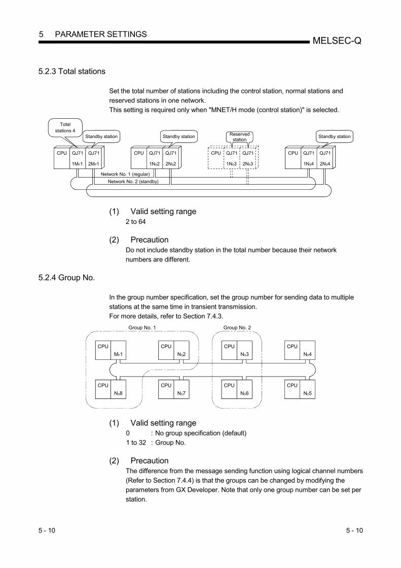
5 - 10 5 - 10
MELSEC-Q 5 PARAMETER SETTINGS
5.2.3 Total stations
Set the total number of stations including the control station, normal stations and
reserved stations in one network.
This setting is required only when "MNET/H mode (control station)" is selected.
CPU QJ71 QJ71
1MP1 2MP1
CPU QJ71 QJ71
1NS2 2NS2
CPU QJ71 QJ71
1NS3 2NS3
Network No. 1 (regular)
Network No. 2 (standby)
CPU QJ71 QJ71
1NS4 2NS4
Total stations 4
Standby station Reservedstation
Standby station Standby station
(1) Valid setting range 2 to 64
(2) Precaution
Do not include standby station in the total number because their network
numbers are different.
5.2.4 Group No.
In the group number specification, set the group number for sending data to multiple
stations at the same time in transient transmission.
For more details, refer to Section 7.4.3.
CPU
MP1
CPU
NS2
CPU
NS3
CPU
NS4
CPU
NS8
CPU
NS7
CPU
NS6
CPU
NS5
Group No. 1 Group No. 2
(1) Valid setting range 0 : No group specification (default)
1 to 32 : Group No.
(2) Precaution
The difference from the message sending function using logical channel numbers
(Refer to Section 7.4.4) is that the groups can be changed by modifying the
parameters from GX Developer. Note that only one group number can be set per
station.

5 - 11 5 - 11
MELSEC-Q 5 PARAMETER SETTINGS
5.2.5 Mode
Set the operation mode of the network module.
The set parameters take effect when the switch setting of the network module is set to
"online".
For the switch setting of each network module, refer to Section 4.2. Selection item Description
Online
(Default)
This mode performs normal operations (the station returns to the network).
Starts data communication at startup and executes automatic return operation. etc.
Online debug mode
This mode places the online station in the send stop status.
The station is recognized as a normal station from other stations and data
communication is performed as follows: : Allowed : Not allowed
Send Receive
Cyclic data (LY/LB/LW)
Transient data
When a programmable controller is being added to the system as shown in the figure
below, the debugging can be executed without stopping the system operation. When
the debugging is completed, cancel the debug mode to execute data linking. This
function is convenient when performing the system expansion while running the
system.
MELSECNET/H
Systems in operation
DebuggingGX Developer
Data receiving enabled
LB/LW
Offline This mode stops operations (disconnecting the station).
Baton pass and data communication with other stations are not executed.
Forward loop test
(optical loop system only)
This mode is to select the hardware test operation that checks the connection status
and the optical fiber cables on the forward loop side.
For details of how to conduct the hardware test, refer to Section 4.7.2.
Reverse loop test
(optical loop system only)
This mode is to select the hardware test operation that checks the connection status
and the optical fiber cable on the reverse loop side.
For details of how to conduct the hardware test, refer to Section 4.7.2.
Station-to-station test
(station to execute test)
This mode selects the station to execute the hardware test for checking a line between
two stations.
For details of how to conduct the station-to-station test refer to Section 4.7.1.
Station-to-station test
(station to be tested)
This mode selects the station on which the hardware test for checking a line between
two stations is executed.
For details of how to conduct the station-to-station test refer to Section 4.7.1.
REMARKS
The mode set in the network parameters for the redundant system must be the same as the operation mode of the network module mounted on system A. Set the operation mode of the network module mounted on system B in the mode selection of the redundant settings (system B). For details of the redundant settings, refer to Section 7.10.4.

5 - 12 5 - 12
MELSEC-Q 5 PARAMETER SETTINGS
5.2.6 Communication speed setting (twisted bus system only)
Set communication speed for the twisted bus system.
The communication speed can be selected in the Network parameter of the control
station.
Normal stations operate according to the communication speed set in the control
station. Therefore the communication speed setting in normal stations is not necessary.
(1) Selection type
Select from the following items: Item Description
Optical/coaxial Set when the optical loop or coaxial bus system is used.
Twist [156kbps]
Set when the twisted bus system at 156kbps to 10Mbps is
used.
Twist [312kbps]
Twist [625kbps]
Twist [1.25Mbps]
Twist [2.5Mbps]
Twist [5Mbps]
Twist [10Mbps]
REMARKS
The communication speed can be checked in the communication speed setting
value (SW0069).
For details of SW, refer to Appendix 4.
(2) Precautions
(a) Total connection cable length must be within the range given in the
specifications. (Refer to Section 3.1.)
If the length is exceeded the range, the following problem may occur. • Frequent communication error • Continuous data link connection and disconnection • No data link
(b) When "Optical/coaxial" is selected in the communication speed setting
parameter of the network parameter data link is performed at 156kbps.

5 - 13 5 - 13
MELSEC-Q 5 PARAMETER SETTINGS
5.2.7 Example of parameter settings
The following example shows the parameter settings for a system that include a
control station, a normal station, and a standby station.
[System configuration]
Q25HCPU QJ71LP21
QJ71BR11
QJ71BR11
1MP1 2NS2 3NS2
Regular network (network No. 2)
Standby network (network No. 3)
2MP1 3MP1 2NS5 3NS5
1NS2 1NS8
Network No. 1
to
to
Valid module during other station access: first module
Controlstation
Normalstation
Standby station
Po
wer
sup
ply
[Screen settings]

5 - 14 5 - 14
MELSEC-Q 5 PARAMETER SETTINGS
5.3 Common Parameters (Network Range Assignment Screen)
The common parameters are used to set the cyclic transmission ranges of LB, LW, LX and LY that can be sent by each station in a single network. The common parameter settings are required only for the control station. The data of the common parameters are sent to the normal stations when the network starts up.
5.3.1 Send range for each station (LB/LW settings)
Assign the send ranges of the link devices (LB/LW) for each station in 16-point units for LB (start 0 to end F) and in one-point unit for LW. The following example shows send range for each station (LB/LW settings) when each of 512 points is assigned to station numbers 1 to 8.
1MP1 Host's send range
1NS2
1NS3
1NS4
1NS5
1NS6
1NS7
1NS8
1MP1
1NS2
1NS3
1NS4
1NS5
1NS6
1NS7
1NS8
1MP1
1NS2
1NS3
1NS4
1NS5
1NS6
1NS7
1NS8
1MP1
1NS2
1NS3
1NS4
1NS5
1NS6
1NS7
1NS8
1MP1
1NS2
1NS3
1NS4
1NS5
1NS6
1NS7
1NS8
Common parametersSend range
for each station0
1FF200
3FF400
5FF600
7FF800
9FFA00
BFFC00
DFFE00
FFF
3FFF
1MP1 1NS2 1NS3 1NS4
1NS51NS61NS71NS8
Network No. 1
to
to
to
to
to
to
to
to
Host's send range
Host's send range
Host's send range
[Screen settings]
POINT (1) In order to enable 32-bit data assurance, it is necessary to set the number of
points of send range for each station in such a way that LB is a multiple of 20H and LW is multiple of 2. Also, each station's head device number must be set in a similar way so that LB is a multiple of 20H and LW is a multiple of 2. (For details of the 32-bit data assurance, refer to Section 6.2.1.)
(2) For the assignment of the same points only to LB and LW, use the identical point assignment setting. For the identical point assignment to LBs and LWs, including low-speed LB and low-speed LW, use equal assignment.
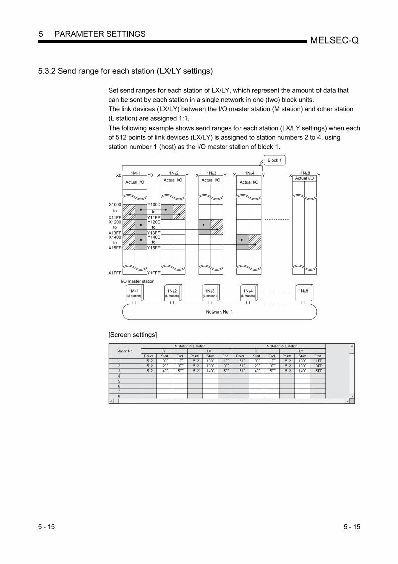
5 - 15 5 - 15
MELSEC-Q 5 PARAMETER SETTINGS
5.3.2 Send range for each station (LX/LY settings)
Set send ranges for each station of LX/LY, which represent the amount of data that
can be sent by each station in a single network in one (two) block units.
The link devices (LX/LY) between the I/O master station (M station) and other station
(L station) are assigned 1:1.
The following example shows send ranges for each station (LX/LY settings) when each
of 512 points of link devices (LX/LY) is assigned to station numbers 2 to 4, using
station number 1 (host) as the I/O master station of block 1.
1MP1 1NS2 1NS3 1NS4 1NS8X0 Y0 X Y X Y X Y X Y
X1FFF Y1FFF
X1000
X11FFX1200
X13FFX1400
X15FF
Y1400
Y15FF
Y1000
Y11FFY1200
Y13FF
Block 1
Actual I/O
1MP1(M station)
I/O master station
1NS2(L station)
1NS3(L station)
1NS4(L station)
1NS8
Network No. 1
Actual I/O Actual I/O Actual I/OActual I/O
to
to
to
to
to
to
[Screen settings]
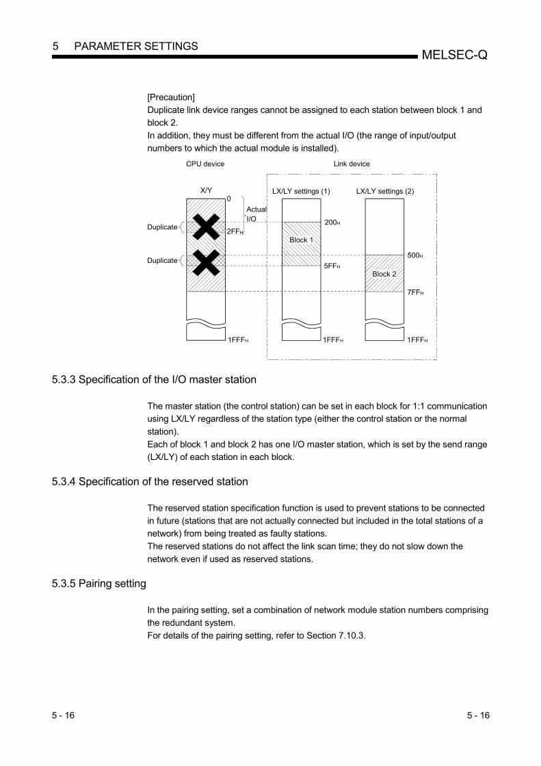
5 - 16 5 - 16
MELSEC-Q 5 PARAMETER SETTINGS
[Precaution]
Duplicate link device ranges cannot be assigned to each station between block 1 and
block 2.
In addition, they must be different from the actual I/O (the range of input/output
numbers to which the actual module is installed).
500H
7FFH
200H
5FFH
LX/LY settings (1) LX/LY settings (2)
Block 2
Block 1
Link deviceCPU device
X/Y
Duplicate
Duplicate
0
1FFFH
2FFH
1FFFH 1FFFH
ActualI/O
5.3.3 Specification of the I/O master station
The master station (the control station) can be set in each block for 1:1 communication
using LX/LY regardless of the station type (either the control station or the normal
station).
Each of block 1 and block 2 has one I/O master station, which is set by the send range
(LX/LY) of each station in each block.
5.3.4 Specification of the reserved station
The reserved station specification function is used to prevent stations to be connected
in future (stations that are not actually connected but included in the total stations of a
network) from being treated as faulty stations.
The reserved stations do not affect the link scan time; they do not slow down the
network even if used as reserved stations.
5.3.5 Pairing setting
In the pairing setting, set a combination of network module station numbers comprising
the redundant system.
For details of the pairing setting, refer to Section 7.10.3.

5 - 17 5 - 17
MELSEC-Q 5 PARAMETER SETTINGS
5.4 Supplementary Settings
The supplementary settings are included in the common parameter settings. They can be used when more specific applications are required. The default settings should normally be used. The supplementary settings (common parameter settings) are required only for the control station. The parameters are sent from the control station to normal stations when the network starts up.
9)
1) 2)
8)
7)6)5)4)3)
Supplementary setting screen select button
[Setting item]
1) Monitoring time This is used to monitor the status of the cyclic transmission between the control station (sub-control station) and normal stations. Set the time to determine whether or not the cyclic transmission is performed normally. Set a smaller value if the control time is short, the cyclic data error detection is shorter than the default (2 s) monitoring time, and the actual link scan time is sufficient. Set a larger value if there are large amounts of cyclic data and the link scan time is more than the default monitoring time due to the effect of noise. Set a value greater than the link scan time in 10 ms units. If a value smaller than the link scan time is set, the data link is disabled; thus, check the current value and set a sufficient value without making it unnecessarily shorter.
• Valid setting time : 1 to 200 10 ms
• Default : 200 10 ms (2 s)
2) Parameter name The parameter name function is used to register the names of parameters to make it easy to understand for which system each parameter is used. Choose the names in such a way that the parameter to be set can easily be recognized later.
• Number of input characters: Up to eight alphabetic characters

5 - 18 5 - 18
MELSEC-Q 5 PARAMETER SETTINGS
3) Constant scan
The constant link scan function is used to maintain the link scan time
constant.
Set a value in the following range to use a constant scan time:
Setting time Constant scan
Blank Not executed (default)
1 to 500 ms Executed using the set time
4) Maximum No. of return to system stations in 1 scan (Refer to Section
3.2.2)
Set the number of faulty stations that can return to the network in one
link scan.
• Valid number of stations : 1 to 64 stations
• Default : 2 stations
5) With multiplex transmission (Refer to Section 7.6)
Set this item when executing the multiplex transmission function.
The multiplex transmission function is used when both the forward and
reverse loops are in the normal status to speed up the transmission
rate using both loops at the same time.
• Default: No multiplex transmission 6) There is a data link through the sub-controlling station when the
controlling station is down (Refer to Section 3.2.2)
Set this item to enable other normal station in the network to continue
cyclic transmission as a substitute station (sub control station) (control
station shift function) if the specified control station is cut off from the
network due to an error.
• Default: Control station switch function enabled 7) Block send data assurance per station/Block receive data assurance
per station (Refer to Section 6.2.2)
Set these items when executing the link data separation prevention
per station in the cyclic transmission.
This allows multiple word data manipulation without interlocks.
However, the separation prevention 1 is valid only for the refresh
processing between the CPU module and the network module.
The default varies depending on the network type.
Network type Default
MELSECNET/H mode "No" for both send and receive
MELSECNET/10 mode
MELSECNET/H Extended mode "Yes" for both send and receive
1: The separation prevention refers to a prevention of link data with
double word precision (32 bits), such as the current value of the
positioning module, from being separated into new data and old
data in one word (16 bits) units due to the cyclic transmission
timing.

5 - 19 5 - 19
MELSEC-Q 5 PARAMETER SETTINGS
8) Transient setting (Refer to Section 7.4.1)
Set the execution conditions for the transient transmission. "Maximum no. of transients in 1 scan"
Set the number of transients (total for one entire network) that a single
network can execute in one link scan.
• Valid setting count : 1 to 255 times
• Default : 2 times
"Maximum no. of transients in one station"
Set the number of transients that a single station can execute in one
link scan.
• Valid setting count : 1 to 10 times
• Default : 2 times
9) Specification of low-speed cyclic transmission (Refer to Section 7.3)
Set the execution conditions under which the link data (LB/LW) is sent
at a low frequency (low-speed cyclic transmission) separately from the
normal cyclic transmission.
The following selections can be made when the send ranges (low-
speed LB, low-speed LW) of each station are set for the low-speed
cyclic transmission. "Transmit data of one station in 1 scan"
Set this item when sending data to be communicated in a batch mode
to other stations at the rate of one station per link scan.
• Default: Disabled "Fixed term cycle interval setting"
The low-speed cyclic transmission is executed at the set frequency.
• Valid setting frequency : 1 to 65535 s (18 hours, 12 minutes and 15 second)
• Default : Disabled
"System times"
The low-speed cyclic transmission is executed according to the set
time.
Hour/minute/second of the system timer cannot be omitted.
• Setting : 1 to 8 points (year/month/date/hour/minute/second)
• Default : Disabled
POINT
Low-speed cyclic transmission cannot be set on the Basic model QCPU,
Q00UJCPU, Q00UCPU, Q01UCPU and safety CPU. Hence, low-speed cyclic
transmission cannot be executed.

5 - 20 5 - 20
MELSEC-Q 5 PARAMETER SETTINGS
5.5 Control Station Return Setting
This parameter is used to specify the type of station used by the control station when
returning to the network in the control station return control function (Refer to Section
3.2.2).
Select this parameter to make the control station return as a normal station without
stopping the baton pass in the system in operation.
The control station return setting is required only for the control station.
(1) When "Return as control station" is selected (default)
The baton pass (cyclic transmission, transient transmission, etc.) temporarily
stops because the control station sends the parameters to the normal stations
and returns to the network.
(2) When "Return as normal station" is selected
The control station returns to the network as a normal station, without stopping
the baton pass in the network.
[Setting screen]
REMARKS
• When "Return as control station" is selected, the network stop time becomes
longer because the baton pass is stopped, but the common parameters can easily
be changed only by resetting the CPU of the control station.
• If "Return as normal station" is selected, the network does not stop because the
control station returns to the network without stopping the baton pass.
However, it is necessary to reset the CPUs of all the stations after changing the
common parameters of the control station while the network is in operation. If only
the CPU of the control station is reset, a parameter mismatch error is detected in
the control station and it is disconnected from the network.

5 - 21 5 - 21
MELSEC-Q 5 PARAMETER SETTINGS
5.6 Station Inherent Parameters (High Performance model QCPU, Process CPU,
Redundant CPU, and Universal model QCPU)
The station inherent parameters are used for rearranging each station's transmission
ranges (LB, LW).
Rearrangement of the each station transmission ranges (LB, LW) eliminates the need
for program modification even if link device settings are expanded during operation.
Also, it can remove unnecessary transmission ranges, keeping only necessary ranges.
(1) Setting items
(a) Display of the setting screen 1) For the control station
Click the Station inherent parameters button on the [Network
assignment] screen (common parameters) to display to display the
following screen.
The settings assigned with common parameters are shown in the
Network range assignment area.
2) For the normal station The screen appears when the Station inherent parameters button is
clicked.
From [Reference network range assignment], common parameters of the control station can be read. (Reference -> Select project -> Read)
This is useful for setting station inherent parameters with the control
station’s network range assignments being viewed.
Values can be set even if no values are displayed in the network range
assignment fields.
The network range assignment fields are merely used as a reference
for Setting 1 and Setting 2.

5 - 22 5 - 22
MELSEC-Q 5 PARAMETER SETTINGS
(b) Setting items
1) Parameter name
Set the parameter name to make it easy to understand for which
system each parameter is used.
• Number of input characters: Up to eight alphabetic characters 2) Switch screens
The windows can be switched using the selection dialogue box (LB
settings, LW settings).
3) Setting 1 and setting 2
• The send ranges of all station numbers can be divided into two:
Setting 1 and Setting 2.
• Any values can be set as long as they are within the network
assignment range (including all stations) of the common parameters.
• Note that even if the ranges are set with the common parameters,
the assigned ranges become invalid for the station numbers for
which nothing is set with Setting 1 and Setting 2 of the station
inherent parameters. 4) Reference network range assignment (Normal station only)
This is used when station inherent parameters are set with the control
station's network range assignments being viewed. With the Reference button, select the project of the control station.
In the Project Name box, select the position of the control station. A click on the Read button displays the control station's network range
assignments in the Network range assignment area.

5 - 23 5 - 23
MELSEC-Q 5 PARAMETER SETTINGS
POINT
(1) Set values for Setting 1 and Setting 2 within the device range specified with a
common parameter.
If a value outside the range is selected, a mismatch error occurs.
Also, duplicate ranges cannot be specified for Setting 1 and Setting 2.
StationNo. 1
Duplicate
Empty
Setting 1 Setting 2 Setting 1 Setting 2
StationNo. 2
StationNo. 3
StationNo. 4
StationNo. 1
StationNo. 2
StationNo. 3
StationNo. 4
StationNo. 1
StationNo. 2
StationNo. 3
StationNo. 4
Empty
StationNo. 1
StationNo. 2
StationNo. 3
StationNo. 4
Duplicate
(2) The station without setting 1 cannot be set setting 2.
(3) The setting number for setting 2 must be larger than the last number in the
whole station of setting 1.
(4) For low-speed cyclic transmission, station inherent parameters cannot be set.
(5) The station inherent parameters cannot be set on the Basic model QCPU
and safety CPU.

5 - 24 5 - 24
MELSEC-Q 5 PARAMETER SETTINGS
(2) Example of settings
The settings shown below are displayed on the screen when the common
parameters (network range assignments) are changed as follows:
1) Move the devices of station number 1. B100 to B1FF B500 to
B5FF
2) Lump the devices of station number 2 to 5 together so that they are
contiguous.
3) Cancel the assignments of station number 6.
[Example of station inherent parameter settings]
StationNo. 1 (a)
0
FF
Station No. 2
100
1FF200
2FF300
3FF400
4FF
Station inherent parameters (LB/LW)
500
5FF
400
4FF
300
3FF
200
2FF
0
1FF
Network module
5FF
500
600
6FF
Refresh
0(B/W)
CPU
Each station
Settings of the station inherent parameters
5FF
Common parameters (LB/LW)
to
to
to
to
to
to
Send/receive data
Station No. 3
Station No. 4
Station No. 5
StationNo. 1 (b)
Station No. 2
Station No. 3
Station No. 4
Station No. 5
StationNo. 1 (b)
StationNo. 1 (a)
Station No. 6
to
to
to
to
to
to

5 - 25 5 - 25
MELSEC-Q 5 PARAMETER SETTINGS
5.7 Refresh Parameters
The refresh parameters are used to transfer the link device data (LB, LW, LX, LY) of
the network module to the devices (X, Y, M, L, T, B, C, ST, D, W, R, ZR) of the CPU
module for operation of the sequence programs.
By eliminating the network refresh of those link devices that are not used by the
sequence programs, the scan time can also be reduced.
Because it is not necessary to transfer the link devices to different devices with the
sequence programs, the number of program steps is reduced and easy-to-understand
programs can be created.
[Refresh parameter setting screen]
4)
3)
1) 2)
5) 6)
The assignment status of the above refresh parameters can be checked with the
assignment image diagram.
The assignment image diagram shows the device assignments made between the
CPU module and the modules set for the No. of module setting.
The refresh parameters cannot be duplicated in the CPU's device settings.
B0
B5FF
B9FF
B1FFF
CPU Network module No. 1 Network module No. 2
Duplicate
Not allowed
LB3FFF LB3FFF
LB5FF
LB9FF
LB0LB0
to to
to

5 - 26 5 - 26
MELSEC-Q 5 PARAMETER SETTINGS
Using the assignment image diagram, assignment errors and duplicate settings between the modules can also be checked. It is a convenient tool to view the assignment status when setting or changing the network refresh parameters. It also displays the interlink transmission parameters; thus, complicated settings among the network modules can be verified.
Assignment image
[Link refresh assignment image]
POINT (1) The assignment image diagram can display schematic images of CC-Link
IE Controller Network, CC-Link IE Field Network and MELSECNET/H (network modules on controller networks, PLC to PLC networks, and remote I/O networks).
(2) Avoid any duplicate settings of the programmable-controller-side devices that are used for the following. • Auto refresh parameters of CC-Link modules • Refresh parameters of network modules • I/O numbers used for I/O modules and intelligent function module • Auto refresh parameters of intelligent function modules • Auto refresh using the CPU shared memory in the multiple CPU system
(3) Do not set the link refresh range that does not exceed the range of the internal user devices to the extended data register(D) or to extended link register(W) respectively.
1) Assignment method
Select the device range input method from either Points/Start or Start/End. • Default: Start/End
2) Transient transmission error history status Select whether to overwrite or retain the error history. • Default: Overwrite
3) Transfer settings on the Link side and the PLC side
Select the device names from the following:
Link side : LX, LY, LB. LW
PLC side : X, Y, M, L, T, B, C, ST, D, W, R, ZR However, if the link side is LX, any of C, T and ST cannot be selected on the CPU side. Set the values for Points/Start/End in 16-point units.

5 - 27 5 - 27
MELSEC-Q 5 PARAMETER SETTINGS
4) Default button
Select this button to automatically assign the default link devices
according to the number of installed modules.
5) Check button
Select this button to check if there are any duplicate parameter data
settings.
6) End setup button
Click this button to return to the network setting screen after
completing the data settings.
REMARKS
[Random cyclic] is for future use. An error will not occur even if it is selected, but no
processing will be performed.

5 - 28 5 - 28
MELSEC-Q 5 PARAMETER SETTINGS
5.7.1 Concept of the link refreshing
(1) Link refresh ranges The ranges that are set in Refresh parameters and that are set with common parameters are refreshed.
(2) Devices for which link refreshing can be executed The following table indicates the devices for which link refreshing can be
executed.
Setting item Devices for which transfer is allowed
Link side device PLC side device
SB transfer SB SB
SW transfer SW SW
Transfer 1 LX, LY, LB, LW X, Y, M, L, B, T, C, ST, D, W, R, ZR
: : :
Transfer 64 LX, LY, LB, LW X, Y, M, L, B, T, C, ST, D, W, R, ZR
REMARKS
The number of refresh parameter settings per module is shown below.
Item
Number of settings
Basic model QCPU Safety CPU
Q00UJCPU
Q00UCPU
Q01UCPU
High Performance model QCPU Process CPU
Redundant CPU Universal model QCPU other than
listed in the left columns
Link device transfer 8 16 64
SB/SW transfer 1 for each

5 - 29 5 - 29
MELSEC-Q 5 PARAMETER SETTINGS
POINT
To use the entire device range (16K points) of LB/LW, either of the following
settings must be made:
1) Change the number of device points of B/W.
2) In the refresh parameters, use devices other than B/W for the
refresh target device of LB/LW. [Example]
To change [Device] of [PLC parameter] in order to use all 16K points of
the LB and LW device range
For the Universal model QCPU, 16.4K words in word device and 64K bits in bit
device can be assigned.
Setting ranges vary depending on the CPU module used.
For details, refer to the user’s manual (Function Explanation, Program Example) for
the CPU module used.
[In the case of Q25HCPU]
Input relayOutput relayInternal relayLatch relayLink relayAnnunciatorLink special relayEdge relayStep relayTimerRetentive timerCounterData registerLink registerLink special register
Device totalWord device totalBit device total
X 8K Y 8K M 8K L 8K B 8K F 2K
SB 2K V 2K S 8K T 2K
ST 0K C 1K D 12K W 8K
SW 2K
28.8K 26.0K 44.0K
8K 8K 8K 4K 16K 2K 2K 2K 8K 2K 0K 1K 4K 16K 2K
29.0K 26.0K 48.0K
[Default] [After change]
L:4K
F:2K
X:8K
Y:8K
M:8K
L:8K
B:8KF:2K
[Default] [After change]
X:8K
Y:8K
M:8K
B:16K

5 - 30 5 - 30
MELSEC-Q 5 PARAMETER SETTINGS
5.7.2 How to set the refresh parameters
(1) Automatic setting with the Default button
(a) High Performance model QCPU, Process CPU, Redundant CPU, and Universal model QCPU 1) When B/W points set in [Device] under [PLC parameter] are 8K points
or more (6K points or more when three modules are mounted) Link devices are assigned as shown below.
B/W0
1FFF
LB/LW0
1FFF
3FFF
B/W0
FFF1000
1FFF
LB/LW0
FFF
4096points
3FFF
B/W0
7FF800
FFF1000
17FF1800
1FFF
LB/LW0
7FF
3FFF
B/W0
7FF800
FFF1000
17FF1800
1FFF
LB/LW0
7FF
3FFF
Installation location
Number of installation
1 Module
2 Modules
3 Modules
4 Modules
CPU Module 1 Module 2 Module 3 Module 4
4096points
to
to
to
to
to
toto
to
to
to
toto
to
to
toto 8192points
2048points
2048points
2048points
2048points
2048points
2048points
2048points
LB/LW
0
FFF
3FFF
LB/LW
0
7FF
3FFF
LB/LW
0
7FF
3FFF
LB/LW
0
7FF
3FFF
LB/LW
0
7FF
3FFF
LB/LW
0
7FF
3FFF
to to
to
to to to

5 - 31 5 - 31
MELSEC-Q 5 PARAMETER SETTINGS
2) When B/W points set in [Device] under [PLC parameter] are less than 8K points (less than 6K points when three modules are mounted)
Link devices equivalent to the B/W points set in [Device] are assigned,
up to the following points for each module. No. of modules Maximum points assignable per module
1 B/W points set in [Device]
2 4K points
3 2K points
4
Example: When B/W points set in [Device] are 5K points
B/W0
LB/LW0
3FFF
B/W0
FFF1000
LB/LW0
FFF
4096points
B/W0
7FF800
FFF1000
LB/LW
7FF
2048points
2048points
1 Module
2 Modules
3 Modules
4 Modules
CPU Module 1 Module 2 Module 3 Module 4
LB/LW
3FFF
LB/LW
7FF
LB/LW
13FF13FF
13FF
3FF
0
3FFF
13FF
3FF
000
3FFF 3FFF 3FFF
B/W0
7FF800
FFF1000
LB/LW
7FF
2048points
2048points
LB/LW
7FF
LB/LW
13FF
3FF
000
3FFF 3FFF 3FFF
LB/LW0
3FFF
5120points
Installation location
Number of installation
to to
to
to
to
to
to
to
to
to toto
totototo
to
to 1024 points
1024 points
1024 points

5 - 32 5 - 32
MELSEC-Q 5 PARAMETER SETTINGS
(b) Basic model QCPU and safety CPU
1) When B/W points set in [Device] under [PLC parameter] are 2K
points or more
Link devices are assigned as shown below.
B/W0
07FF
LB/LW0
07FF
2048points1 Module
CPU Module 1Installation
locationNumber of installation
to to
2) When B/W points set in [Device] under [PLC parameter] are less
than 2K points
The B/W points set in [Device] are assigned. Example: When B/W points set in [Device] are 1K points
B/W0
03FF
LB/LW0
1 Module
CPU
03FF
Module 1
Installation location
Number of installation
1024pointsto to

5 - 33 5 - 33
MELSEC-Q 5 PARAMETER SETTINGS
(2) Manual setting by direct input
1) Select "Assignment method".
Select "Points/Start" when entering link device points and start
addresses. Select "Start/End" when entering start and end addresses of link
devices. 2) Configure the settings for the link side and CPU side devices.
Example: When "Start/End" is selected
LB0
7FF
3FFF
B
300
AFF
1FFF
2048points
Network module CPU
For decimal bit devices, the start address must be a multiple of 16.
to
to

5 - 34 5 - 34
MELSEC-Q 5 PARAMETER SETTINGS
POINT
(1) When setting the CPU side device range, check if:
• The refresh range does not overlap with any other range (e.g. actual I/O). • The CPU side device range is within the range set in [Device] of [PLC
parameter].
Device ranges can be checked by selecting [Tools] – [Check parameters] in GX Developer.
(2) When the interlink transmission parameters are set, do not set the device
range of the transfer destination in a refresh range. Otherwise, the correct data cannot be sent to other stations.
Network module No. 1CPU
Refresh range
Transfer to
Refresh range
Network module No. 2
Transfer from

5 - 35 5 - 35
MELSEC-Q 5 PARAMETER SETTINGS
(3) When no refresh parameters are set
(Other than Universal model QCPU and safety CPU)
(a) High Performance model QCPU, Process CPU, and Redundant CPU Link devices are assigned as shown below.
B/W0
1FFF
LB/LW0
1FFF
3FFF
B/W0
FFF1000
1FFF
LB/LW0
FFF
4096points
3FFF
B/W0
7FF800
FFF1000
17FF1800
1FFF
LB/LW0
7FF
3FFF
B/W0
7FF800
FFF1000
17FF1800
1FFF
LB/LW0
7FF
3FFF
Installation location
Number of installation
1 Module
2 Modules
3 Modules
4 Modules
CPU Module 1 Module 2 Module 3 Module 4
4096points
to
to
to
to
to
toto
to
to
to
toto
to
to
toto 8192points
2048points
2048points
2048points
2048points
2048points
2048points
2048points
LB/LW
0
FFF
3FFF
LB/LW
0
7FF
3FFF
LB/LW
0
7FF
3FFF
LB/LW
0
7FF
3FFF
LB/LW
0
7FF
3FFF
LB/LW
0
7FF
3FFF
to to
to
to to to

5 - 36 5 - 36
MELSEC-Q 5 PARAMETER SETTINGS
POINT
When B/W points less than the following are set in [Device] under [PLC parameter], set refresh parameters accordingly. Or, increase the B/W points to the following
value or more in [Device].
No. of modulesDevice points in [Device]
1
2
3
4
B W
8K points
8K points
8K points
8K points
8K points
8K points
6K points 6K points
(b) Basic model QCPU Link devices are assigned as shown below.
B/W0
07FF
LB/LW0
07FF
2048points1 Module
CPU Module 1Installation
locationNumber of installation
to to
POINT
When B/W points set in [Device] under [PLC parameter] are less than 2K points,
set refresh parameters accordingly. Or, increase the B/W points to 2K points or more in [Device].

5 - 37 5 - 37
MELSEC-Q 5 PARAMETER SETTINGS
(4) Setting example
The following shows an example of the refresh parameter settings:
[System configuration]
CPU QJ71
LP21
QJ71
BR11
QJ71
BR11
1MP1 2NS2 3NS2
Regular network (network No. 2)
Standby network (network No. 3)
Control station
2MP1 3MP1 2NS5 3NS5
1NS8 1NS2
Network No. 1
to
to
Normal station
Pow
er
sup
ply
Standby station
[Parameter assignments]
CPU Network module (1MP1)
M0
4095
B
1FFF
0 to 1FF300 to 4FF600 to 7FF900 to AFFC00 to DFFF00 to 10FF
1200 to 13FF1500 to 16FF
W0
1FFF
FFF1000
LW
FFF
3FFF
LB
3FFF
LW
1000
3FFF
LB
3FFF
0
FFF
1FFF
0 0
0 to 1FF300 to 4FF600 to 7FF900 to AFFC00 to DFFF00 to 10FF
1200 to 13FF1500 to 16FF
to
tototo
to to
to
Network module (2NS2)

5 - 38 5 - 38
MELSEC-Q 5 PARAMETER SETTINGS
[Setting screen] The following shows the settings of the refresh parameters for each module that
are displayed on the screen.
Settings of module 1 (1MP1) (transfer SB, transfer SW, transfers 1 to 6)
(Transfers 7 to 9)
Settings of module 2 (2NS2) (transfer SB, transfer SW, transfers 1 and 2)

5 - 39 5 - 39
MELSEC-Q 5 PARAMETER SETTINGS
5.8 Valid Module During Other Station Access
This parameter is used to specify any of the following modules to be relayed when a data communication request for which the network number of the access target programmable controller station cannot be specified from the host (access from the serial communication module (A compatible 1C frame), the Ethernet module (A compatible 1E frame), etc. to other stations) is issued. • CC-Link IE Controller Network, CC-Link IE Field Network, MELSECNET/H,
MELSECNET/10 module • Ethernet module This setting is not required when a data communication request for which the network number can be specified, such as the serial communication module (QnA compatible 3C frame, QnA compatible 4C frame) or Ethernet module (QnA compatible 3E frame), is used. Leave it as the default (1) setting. For details of the serial communication module or Ethernet module protocol, refer to the MELSEC-Q/L MELSEC Communication Protocol Reference Manual.
[Screen settings]
Select from the selection dialogue box.
(Example) In the example below, the personal computer connected to the serial communication module (QJ71C24) can communicate with the station on network number 2 where the network module 3 is connected.
Module 1
Valid module No. for access to other stations: 3
A compatible 1C frame
Network No. 1
Network No. 3
Network No. 2
Module 2 Module 3 Module 4
Power supply module
QX41QCPU QY41P QJ71LP21
QJ71E71-100
QJ71LP21
QJ71LP21
QJ71C24
Ethernet
QX41
QJ71LP21
QCPUPower supply module

5 - 40 5 - 40
MELSEC-Q 5 PARAMETER SETTINGS
5.9 Standby Station Compatible Module (High Performance model QCPU and Process CPU)
This parameter is set to configure a simple dual-structured system.
Specify a regular station to be paired with the standby station. If the set regular network is down, the network of the wait station (standby station) is
enabled.
Click the Standby station compatible module button to display the "Stand by station /Remote master station compatible module" window, and select the corresponding
module.
• Default: No setting
Set a network module to be used as a regular station.
Click on the standby station compatible module button.

5 - 41 5 - 41
MELSEC-Q 5 PARAMETER SETTINGS
[Setting example]
Po
wer
sup
ply QJ71
LP21QJ71BR11
QJ71BR11
1MP1 2NS2 3NS2
Regular network (network No. 2)
Standby network (network No. 3)
Controlstation
2MP1 3MP1 2NS5 3NS5
1NS8 1NS2
Network No. 1
to
to
Q25HCPU
Normalstation
Standby station
To use the 3NS2 station as the standby station for the normal station 2NS2 as shown in
the figure above, select "Module 2" in the "Standby station compatible module" window
below.
POINT
Since the Basic model QCPU, Redundant CPU, Universal model QCPU, and
safety CPU are not compatible with a simple dual-structured system, this setting is not available.

5 - 42 5 - 42
MELSEC-Q 5 PARAMETER SETTINGS
5.10 Writing Parameters to the CPU
To enable the network parameter settings, they must be written to the CPU using the
Write to PLC function of GX Developer. The PLC parameters are written as well when the network parameters are written.
To write the parameters to a programmable controller of other station than the one that
connects GX Developer via the MELSECNET/H, change the specification of the connection destination of GX Developer.
For more information on how to use this function, refer to the GX Developer Operating
Manual.
(1) Select the Write to PLC function
(2) Select the parameter as a file to be written, and then execute.

6 - 1 6 - 1
MELSEC-Q 6 PROGRAMMING
6 PROGRAMMING
When applying any of the program examples introduced in this chapter to the actual
system, verify the applicability and confirm that no problems will occur in the system
control.
6.1 Programming Precautions
This section explains the precautions in creating programs using data on the network.
6.1.1 Interlock related signals
A list of the interlock signal devices used in the sequence programs is provided below.
For other explanations, such as the operation status and setting status of the host and
other stations, refer to Appendix 3, "List of the Link Special Relays (SB)" and Appendix
4, "List of the Link Special Registers (SW)".
When multiple network modules are installed, the interlock signal devices are
refreshed to the devices on the CPU side at 512 points (0H to 1FFH) intervals according
to the default settings as shown below.
POINT
The Q series uses the link special relays (SB) and the link special registers (SW) in
the entire intelligent function module. Therefore, it is important to manage SB/SW
properly so that duplicate SBs and SWs are not used in a program.
Assignments of the link special relay (SB) and the link special register (SW) when multiple modules are installed
Mounting
Position Device
1st module 2nd module 3rd module 4th module
SB 0H to 1FFH 200H to 3FFH 400H to 5FFH 600H to 7FFH
SW 0H to 1FFH 200H to 3FFH 400H to 5FFH 600H to 7FFH
6

6 - 2 6 - 2
MELSEC-Q 6 PROGRAMMING
List of Interlock Devices
No. Name Description
Use permitted/prohibited
Control
station
Normal
station
Remote
master
station
Remote I/O
station
Loop Bus Loop Bus Loop Bus Loop Bus
SB0020 (32)
Module status
Indicates the communication status between the network module and CPU module.
Off: Normal On: Abnormal
SB0047 (71)
Baton pass status (host)
Indicates the host's baton pass status (transient transmission enabled).
Off: Normal On: Abnormal
When an error is identified, the cause of the error can be checked in Baton pass status (host) (SW0047) and Cause of baton pass interruption (SW0048).
SB0049 (73)
Host data link status
Indicates the host's data link operation status. Off: Normal On: Abnormal
When an error is identified, the cause of the error can be checked in Cause of data link stop (SW0049).
1 SB0070
(112)
Baton pass status of each station
Indicates the baton pass status of each station. (Not applicable to reserved stations and the station with the maximum station number or higher)
Off: All stations normal On: Faulty station exists
When any faulty station exists, each station status can be checked in Baton pass status of each station (SW0070 to SW0073). Depending on the timing of the link refresh, Baton pass status of each station (SW0070 to SW0073) and the update may be offset by one sequence scan.
1 SB0074
(116)
Cyclic transmission status of each station
Indicates the cyclic transmission status of each station. (Not applicable to reserved stations and the station with the maximum station number or higher)
Off: All stations are executing data linking On: Stations that are not executing data linking exist
When any non-executing station exists, each station status can be checked in Cyclic transmission status of each station (SW0074 to SW0077). Depending on the timing of the link refresh, Cyclic transmission status of each station (SW0074 to SW0077) and the update may be offset by one sequence scan.
1 SW0070
(112)/ SW0071
(113)/ SW0072
(114)/ SW0073
(115)
Baton pass status of each station
Stores the baton pass status of each station (Including the host). <Online>
0: Normal (including the stations with the maximum station number and smaller numbers as well as reserved stations)
1: Abnormal <Offline test>
0: Normal 1: Abnormal (including the stations with the maximum station
number and smaller numbers as well as reserved stations)
16
32
48
64
15 14 13 5 4 3 2 1
31 30
47 46
63 62
29
45
61
21 20 19 18 17
37 36 35 34 33
53 52 51 50 49
to
to
to
to
b15 b14 b13 b12 b4 b3 b2 b1 b0
SW0070
SW0071
SW0072
SW0073
to
Numbers 1 to 64 in the above table indicate the station numbers.
[Availability column] Loop: optical loop, Bus: coaxial/twisted bus
: Available, : Not available
1: Valid only when SB0047 is off. When it turns on (error), the last data are retained.
6

6 - 3 6 - 3
MELSEC-Q 6 PROGRAMMING
List of Interlock Devices (Continued)
No. Name Description
Use permitted/prohibited
Control
station
Normal
station
Remote
master
station
Remote I/O
station
Loop Bus Loop Bus Loop Bus Loop Bus
1
SW0074
(116)/
SW0075
(117)/
W0076
(118)/
SW0077
(119)
Cyclic transmission
status of each
station
Stores the cyclic transmission status of each station (including the
host).
0: Executing cyclic transmission (including the station with the
maximum station number and smaller number as well as
reserved stations)
1: Cyclic transmission not executed
16
32
48
64
15 14 13 5 4 3 2 1
31 30
47 46
63 62
29
45
61
21 20 19 18 17
37 36 35 34 33
53 52 51 50 49
to
to
to
to
b15 b14 b13 b12 b4 b3 b2 b1 b0
SW0074
SW0075
SW0076
SW0077
to
Numbers 1 to 64 in the above table indicate the station numbers.
If a CPU module installed together with QJ71LP21S-25 is turned OFF, detection of a data link error may take more time than usual. For immediate detection of a data link error, program an interlock using the link relay (LB) in each station's send range. (Refer to Section 6.2.3.)
1
SW01FC
(508)/
SW01FD
(509)/
SW01FE
(510)/
SW01FF
(511)
Redundant system
status (3)
Indicates the operation status of each station's CPU (control system/standby system).
0: The host station CPU is on the control system (including the single CPU system) (including stations exceeding the maximum station number and reserved stations).
1: The host system CPU is on the standby system.
16
32
48
64
15 14 13 5 4 3 2 1
31 30
47 46
63 62
29
45
61
21 20 19 18 17
37 36 35 34 33
53 52 51 50 49
b15 b14 b13 b12 b4 b3 b2 b1 b0
SW01FC
SW01FD
SW01FE
SW01FF
Numbers 1 to 64 in the above table indicate the station numbers.
to
to
to
to
to
[Availability column] Loop: optical loop, Bus: coaxial/twisted bus
: Available, : Not available
1: Valid only when SB0047 is off. When it turns on (error), the last data are retained.

6 - 4 6 - 4
MELSEC-Q 6 PROGRAMMING
6.1.2 Program example
Provide interlocks in programs according to the link status of the host and other
stations.
The following example shows an interlock in the communication program that uses the
link status of the host (SB0047, SB0049) and the link status of station number 2
(SW0070 bit 1, SW0074 bit 1).
(Example)
Set the following values for the timer constant K . Baton pass status
(T0, T2)
More than (link scan time 6) + (target station CPU sequence scan time
2)
Cyclic transmission status
(T1, T3) More than (link scan time 3)
Reason: This way the control is not stopped even if the network detects an
instantaneous error due to a faulty cable condition and noise interference.
Also, the multipliers of 6, 2 and 3 are used as examples.
REMARKS
For details of interlocks for special link instructions, refer to Section 7.4.5.

6 - 5 6 - 5
MELSEC-Q 6 PROGRAMMING
6.2 Cyclic Transmission
The link scan of MELSECNET/H and the sequence scan of the programmable
controller operate asynchronously.
Thus, the link refresh executed per sequence scan is asynchronous with the link scan.
Depending on the timing of the link refresh, link data with data types of more than 32
bits (two words), such as the ones below, may be broken up into new and old data,
which may coexist in 16-bit (one word) units.
• Floating point data
• Current values of positioning module, command speed.
The MELSECNET/H provides the following functions for making handling of the link
data easy. However, when the conditions (32-bit data assurance execution conditions)
are not met, provide interlocks according to the example in Section 6.2.3.
• 32-bit data assurance : Section 6.2.1
• Station-based block data assurance for
cyclic data : Section 6.2.2
6.2.1 32-bit data assurance
32-bit data precision is assured automatically by setting parameters so that the
following conditions 1) to 4) are satisfied.
If conditions 1) to 4) are not satisfied, a warning for 32-bit data separation is displayed
during setting with GX Developer.
1) The start device number of LB is a multiple of 20H.
2) The number of assigned LB points per station is a multiple of 20H.
3) The start device number of LW is a multiple of 2.
4) The number of assigned LW points per station is a multiple of 2.
Parameter settings for network range assignments
4)2) 1) 3) 4)2) 1) 3)
Refreshing link devices that satisfy the above conditions 1) to 4) ensures consistency
of 32-bit data.
For the send data of less than 32 bits, an interlocked program is not required if the
above conditions are satisfied.
QCPU QJ71BR11
I/O QCPU QJ71BR11
I/O
Pos
ition
ing QCPU QJ71
BR11I/O
Floating point
Current values, command speed, 32-bit I/O data, etc.
MELSECNET/H
Pos
ition
ing

6 - 6 6 - 6
MELSEC-Q 6 PROGRAMMING
POINT (1) When handling data larger than 32 bits (two words), enable the station-based
block data assurance described in Section 6.2.2, or apply interlocks in the programs by seeing the interlock program example in Section 6.2.3.
(2) When the network is set up in the MELSECNET/10 mode, 32-bit data
assurance is valid only stations with QCPU. For those with ACPU/QnACPU,
set interlock referring to interlock program example in Section 6.2.3.

6 - 7 6 - 7
MELSEC-Q 6 PROGRAMMING
6.2.2 Station-based block data assurance for cyclic data
Since handshakes are performed between a CPU module and a network module for link refresh, consistency of cyclic data is assured for each station (link data separation prevention per station 1). As shown below, set the send and receive parameters as needed. These settings can be made using the common parameters (supplementary settings) only for the control station. The default varies depending on the network type.
Network type Default MELSECNET/H mode
"No" for both send and receive MELSECNET/10 mode MELSECNET/H Extended mode "Yes" for both send and receive
Network range assignments Supplementary settings
By selecting both [Block send data assurance per station] and [Block receive data assurance per station], an interlock for the link data between the stations to be set becomes unnecessary.
Network module LWCPU module device W
Refresh A
Refresh B
Updated portion of refresh A
Refresh C
Updated portion of refresh B
Updated portion of refresh C
Station number 1
Station number 2(Host)
Station number 3
Station number 4
Data assured
Data assured
Data assured
Data assured
<Precautions> (1) In order to enable the station-based block data assurance, refresh parameters
must be set. (Refer to Section 5.7.) (2) Station-based block data assurance for cyclic data is not required for normal
stations.
POINT (1) The station-based block data assurance applies only to the refresh
processing. To use the direct access (J \ designation) of the link devices, provide interlocks in the programs.
(2) For the transmission delay time calculation for the case where the Block send/receive data assurance per station is enabled, refer to Section 3.3.2 (1) (a) POINT.
(3) When the network is set up in the MELSECNET/10 mode, station-based block data assurance is valid only for stations with QCPU. For those with ACPU/QnACPU, provide interlocks in the program referring to the program example in Section 6.2.3.
1: The separation prevention refers to a prevention of link data with double word precision (32 bits), such as the current value of the positioning module, from being separated into new data and old data in one word (16 bits) units due to the cyclic transmission timing.

6 - 8 6 - 8
MELSEC-Q 6 PROGRAMMING
6.2.3 Interlock program example
When data larger than two words (32 bits) are transferred at one time with the 32-bit
data assurance function or the station-based block data assurance function disabled,
old and new data may be mixed in units of one word (16 bits).
As in the example below, provide interlocks in a program using the oldest number of
either the link relay (B).
1) The send command turns on. 2) The contents of D0 to D2 are stored in W0 to W2. 3) Upon completion of storage in W0 to W2, B0 for handshaking turns
on. 4) By cyclic transmission, the link relay (B) is sent after the link register
(W), which turns on B0 of the receiving station. 5) The contents of W0 to W2 are stored in D100 to D102. 6) Upon completion of storage in D100 to D102, B100 for handshaking
turns on. 7) When the data is transmitted to the receiving station, B0 turns off.
POINT
This interlock program example is not usable in the MELSECNET/H Extended mode. Use the station-based block data assurance.

6 - 9 6 - 9
MELSEC-Q 6 PROGRAMMING
6.3 Link Dedicated Instruction List
The following table outlines the instructions that can be used for the MELSECNET/H.
For details of the format and program examples of each instruction, refer to the
applicable section listed in the Reference section column.
Link dedicated instruction list
Instruction Name Description Target station Reference
section
SEND Send data
SEND : Writes data to the target station (network module)
having the target network number. 1
• QCPU
• RCPU
• LCPU
• QnACPU
• PC interface board 3
Section 7.4.5 (1)
RECV : Reads data sent with SEND to the CPU device.
1
RECV Receive data
CPU Network module CPUNetwork module
Channel 1
Channel 2
Channel 3
Channel 4
Channel 5
Channel 6
Channel 7
Channel 8
SEND RECV
Logical channel 1 (channel 1)
Logical channel 2 (channel 2)Logical channel 3 (channel 3)
Logical channel 4 (channel 4)Logical channel 5 (channel 5)
Logical channel 6 (channel 6)
Logical channel 7 (channel 7)
Logical channel 8 (channel 8)
• QCPU
• RCPU
READ
SREAD
Read word
device from
other station
Reads the CPU device data (16-bit units) from the target
station having the target network number.
CPU CPU
Word device
2594
READ
Word device2594
Network module
Channel 1
Channel 2
Channel 3
Channel 4
Channel 5
Channel 6
Channel 7
Channel 8
Network module
• QCPU
• RCPU
• LCPU
• QnACPU
• Safety CPU
Section 7.4.5 (2)
WRITE
SWRITE
Write word
device to
other station
Writes data (16-bit units) to the CPU device of the target
station having the target network number. 2
(SWRITE can turn on the device of the target station.)
WRITE
CPU CPU
361
Network module
Channel 1
Channel 2
Channel 3
Channel 4
Channel 5
Channel 6
Channel 7
Channel 8
Network module
Word device
• QCPU
• RCPU
• LCPU
• QnACPU
Section 7.4.5 (2)
1: Cannot be used if the executing station or target station is a safety CPU.
2: Writing to a safety CPU is not allowed from other stations.
3: Can access a PC interface board with the SEND/RECV functions.
• MELSECNET/H interface board
• MELSECNET/10 interface board
• CC-Link IE Controller Network interface board
• CC-Link IE Field Network interface board
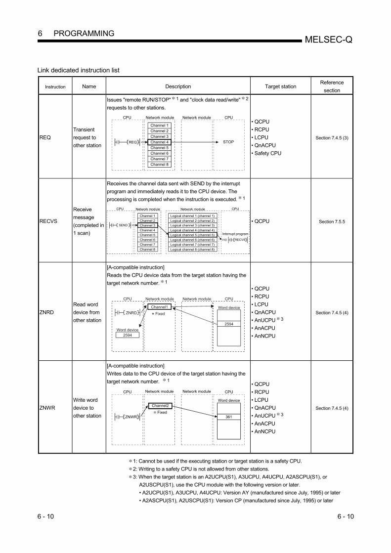
6 - 10 6 - 10
MELSEC-Q 6 PROGRAMMING
Link dedicated instruction list
Instruction Name Description Target station Reference
section
REQ
Transient
request to
other station
Issues "remote RUN/STOP" 1 and "clock data read/write" 2
requests to other stations.
CPU CPU
STOPREQ
Network module
Channel 1
Channel 2
Channel 3
Channel 4
Channel 5
Channel 6
Channel 7
Channel 8
Network module
• QCPU
• RCPU
• LCPU
• QnACPU
• Safety CPU
Section 7.4.5 (3)
RECVS
Receive
message
(completed in
1 scan)
Receives the channel data sent with SEND by the interrupt
program and immediately reads it to the CPU device. The
processing is completed when the instruction is executed. 1
CPU CPU
SEND
RECVSI10
Interrupt program
Network module Network module
Channel 1
Channel 2
Channel 3
Channel 4
Channel 5
Channel 6
Channel 7
Channel 8
Logical channel 1 (channel 1)
Logical channel 2 (channel 2)Logical channel 3 (channel 3)
Logical channel 4 (channel 4)
Logical channel 5 (channel 5)
Logical channel 6 (channel 6)
Logical channel 7 (channel 7)
Logical channel 8 (channel 8)
• QCPU Section 7.5.5
ZNRD
Read word
device from
other station
[A-compatible instruction]
Reads the CPU device data from the target station having the
target network number. 1
• QCPU
• RCPU
• LCPU
• QnACPU
• AnUCPU 3
• AnACPU
• AnNCPU
Section 7.4.5 (4)
ZNWR
Write word
device to
other station
[A-compatible instruction]
Writes data to the CPU device of the target station having the
target network number. 1
CPU CPU
Word device
361ZNWR
Channel2
Fixed
Network module Network module
• QCPU
• RCPU
• LCPU
• QnACPU
• AnUCPU 3
• AnACPU
• AnNCPU
Section 7.4.5 (4)
1: Cannot be used if the executing station or target station is a safety CPU.
2: Writing to a safety CPU is not allowed from other stations.
3: When the target station is an A2UCPU(S1), A3UCPU, A4UCPU, A2ASCPU(S1), or
A2USCPU(S1), use the CPU module with the following version or later.
• A2UCPU(S1), A3UCPU, A4UCPU: Version AY (manufactured since July, 1995) or later
• A2ASCPU(S1), A2USCPU(S1): Version CP (manufactured since July, 1995) or later

6 - 11 6 - 11
MELSEC-Q 6 PROGRAMMING
Link dedicated instruction list
Instruction Name Description Target station Reference
section
RRUN Remote RUN
"Remote RUN" performed for other stations' CPU modules 1
CPU CPU
RUNRRUN
Network module
Channel 1
Channel 2
Channel 3
Channel 4
Channel 5
Channel 6
Channel 7
Channel 8
Network module
• QCPU
• RCPU
• LCPU
Section 7.4.5 (5)
RSTOP Remote
STOP
"Remote STOP" performed for other stations' CPU
modules 1
CPU CPU
STOPRSTOP
Network module
Channel 1
Channel 2
Channel 3
Channel 4
Channel 5
Channel 6
Channel 7
Channel 8
Network module
• QCPU
• RCPU
• LCPU
Section 7.4.5 (5)
RTMRD
Other station
clock data
read
"Read Clock Data" performed for other stations' CPU modules
CPU CPU
RTMRD
Network module
Channel 1
Channel 2
Channel 3
Channel 4
Channel 5
Channel 6
Channel 7
Channel 8
Network module
Word device
Clock data
Clock data
• QCPU
• RCPU
• LCPU
Section 7.4.5 (6)
RTMWR
Other station
clock data
written
"Write Clock Data" performed for other stations' CPU modules
2
CPU CPU
RTMWR
Network module
Channel 1
Channel 2
Channel 3
Channel 4
Channel 5
Channel 6
Channel 7
Channel 8
Network module
Clock data
• QCPU
• RCPU
• LCPU
Section 7.4.5 (6)
1: Cannot be used if the executing station or target station is a safety CPU.
2: Writing to a safety CPU is not allowed from other stations.

6 - 12 6 - 12
MELSEC-Q 6 PROGRAMMING
POINT (1) Link dedicated instructions must be executed in online mode.
Execution of the link dedicated instructions is not allowed in offline mode. (2) Turn off the executing link instruction after the completion device turns on. (3) When the link dedicated instruction is used to access the other station
programmable controller during network diagnosis, the execution of the link dedicated instruction may be delayed. After taking the following measures, perform network diagnosis processing and execute the link dedicated instruction. • Execute the COM instruction. • Secure the communication processing security time for 2 to 3ms.
For the Basic model QCPU, High Performance model QCPU, Process CPU, and Redundant CPU, set it by the special register SD315. For the Universal model QCPU, set it by the service processing setting of the PLC parameter (PLC system) of GX Developer.
(4) Do not execute any instruction that cannot be executed to AnUCPU stations. If executed, the AnUCPU may detect "MAIN CPU DOWN" or "WDT ERROR" and stop its operation.
(5) To execute such an instruction to all of the network which contains an AnUCPU station, use group specification to exclude the AnUCPU station.

6 - 13 6 - 13
MELSEC-Q 6 PROGRAMMING
6.4 Using the Link Special Relays (SB)/Link Special Registers (SW)
The data linking information is stored in the link special relays (SB)/link special
registers (SW).
They can be used by the sequence programs, or used for investigating faulty areas
and the causes of errors by monitoring them.
For details, refer to Appendixes 3 and 4.
(1) Cyclic transmission stop/restart
Cyclic transmission stop/restart is executed through the GX Developer network
tests, but it also can be executed with link special relay (SB) and link special
register (SW). Refer to Section 7.8)
(a) Cyclic transmission stop/restart
(Cyclic transmission stop) 1) In the following link special register (SW), specify a station for
stopping cyclic transmission. • Specification of target station
Link stop/startup direction content (SW0000) • Specification of station No.
Link stop/startup direction content (SW0001 to SW0004) 2) Turn System link stop (SB0003) ON.
3) When the network module accepts a request, Cyclic transmission
stop acknowledgment status (system) (SB0052) is turned ON.
4) When the cyclic transmission stop is completed, Cyclic transmission
stop completion status (system) (SB0053) is turned ON.
5) The station No. of the station that performed the cyclic transmission
stop request is stored in Data linking stop request station (SW004A).
(Saved in the station which received the stop request.)
6) If the cyclic transmission stop is completed abnormally, an error code
will be stored in Data linking stop status (entire system) (SW0053).
7) Turn System link stop (SB0003) OFF.

6 - 14 6 - 14
MELSEC-Q 6 PROGRAMMING
(Cyclic transmission restart) 8) In the following link special register (SW), specify a station for
restarting cyclic transmission. • Specification of target station
Link stop/startup direction content (SW0000) • Specification of station No.
Link stop/startup direction content (SW0001 to SW0004) 9) Turn System link startup (SB0002) ON.
10) When the network module accepts a request, Cyclic transmission
start acknowledgment status (system) (SB0050) is turned ON.
11) When the cyclic transmission restart is completed, Cyclic transmission
start completion status (system) (SB0051) is turned ON.
12) If the cyclic transmission restart is completed abnormally, an error
code will be stored in Data linking start status (entire system)
(SW0051).
13) Turn System link startup (SB0002) OFF.
No. Description No. Description
SB0002 System link startup SW0000
Link stop/startup direction content SB0003 System link stop
SW0001 to
SW0004
SW004A Data linking stop request station
SB0050 Cyclic transmission start
acknowledgment status (system)
SB0051 Cyclic transmission start completion
status (system) SW0051 Data linking start status (entire system)
SB0052 Cyclic transmission stop acknowledgment
status (system)
SB0053 Cyclic transmission stop completion
status (system) SW0053 Data linking stop status (entire system)

6 - 15 6 - 15
MELSEC-Q 6 PROGRAMMING
(b) Cyclic transmission stop/restart of the host
(Cyclic transmission stop) 1) Turn Link stop (host) (SB0001) ON.
2) When the network module accepts a request, Cyclic transmission
stop acknowledgment status (host) (SB004E) is turned ON.
3) When the cyclic transmission stop is completed, Cyclic transmission
stop completion status (host) (SB004F) is turned ON.
4) If the cyclic transmission stop is completed abnormally, an error code
will be stored in Data linking stop status (host) (SW004F).
5) Turn Link stop (host) (SB0001) OFF.
(Cyclic transmission restart) 6) Turn Link startup (host) (SB0000) ON.
7) When the network module accepts the request, Cyclic transmission
start acknowledgment status (host) (SB004C) is turned ON.
8) When the cyclic transmission restart is completed, Cyclic
transmission start completion status (host) (SB004D) is turned ON.
9) If the cyclic transmission restart is completed abnormally, an error
code will be stored in Data linking start status (host) (SW004D).
10) Turn Link startup (host) (SB0000) OFF.
No. Description No. Description
SB0000 Link startup (host)
SB0001 Link stop (host)
SB004C Cyclic transmission start
acknowledgment status (host)
SB004D Cyclic transmission start completion
status (host) SW004D Data linking start status (host)
SB004E Cyclic transmission stop acknowledgment
status (host)
SB004F Cyclic transmission stop completion
status (host) SW004F Data linking stop status (host)

6 - 16 6 - 16
MELSEC-Q 6 PROGRAMMING
(2) Checking data link
The data link status is checked through the GX Developer network diagnostics,
but it also can be checked with link special relay (SB) and link special register
(SW). (Refer to Sections 8.1.1 and 8.1.2.) (a) Check the data link status of other stations
1) Link scan time etc., can be checked in SW005A to SW005B and
SW006B to SW006D.
2) If an error occurs to data link, either of the following link special
relays (SB) will be turned ON.
• Baton pass status of each station (SB0070)
• Cyclic transmission status of each station (SB0074)
3) When Baton pass status of each station (SB0070) is turned ON, the
station No. of a station where an error has occurred is stored in Baton
pass status of each station (SW0070 to SW0073).
When Cyclic transmission status of each station (SB0074) is turned
ON, the station No. of a station where an error has occurred is stored
in Cyclic transmission status of each station (SW0074 to SW0077).
4) The details of the cause of an error can be checked with the link special
relay (SB) and link special register (SW) of the station No. for a station
where the error has occurred. (Refer to (2)(b) in this Section)
No. Description No. Description
SW005A Maximum baton pass station
SW005B Maximum cyclic transmission station
SW006B Maximum link scan time
SW006C Minimum link scan time
SW006D Current link scan time
SB0070 Baton pass status of each station SW0070 to
SW0073 Baton pass status of each station
SB0074 Cyclic transmission status of each station SW0074 to
SW0077 Cyclic transmission status of each station

6 - 17 6 - 17
MELSEC-Q 6 PROGRAMMING
(b) Checking data link status of the host
1) Link scan time etc., can be checked in SW005A to SW005B and
SW006B to SW006D.
2) If an error occurs to data link, either of the following link special
relays (SB) will be turned ON.
• Baton pass status (host) (SB0047)
• Host data link status (SB0049)
3) The cause of an error is stored in the following link special registers
(SW).
• Baton pass status (host) (SW0047)
• Cause of baton pass interruption (SW0048)
• Cause of data link stop (SW0049)
No. Description No. Description
SB0047 Baton pass status (host) SW0047 Baton pass status (host)
SW0048 Cause of baton pass interruption
SB0049 Host data link status SW0049 Cause of data link top
SW005A Maximum baton pass station
SW005B Maximum cyclic transmission station
SW006B Maximum link scan time
SW006C Minimum link scan time
SW006D Current link scan time

6 - 18 6 - 18
MELSEC-Q 6 PROGRAMMING
(3) Checking transient transmission errors
Transient transmission errors are checked through the GX Developer network
diagnostics, but they also can be checked with link special relays (SB) and link
special registers (SW). (Refer to Section 8.1.4) 1) When a transient transmission error occurs, Transient error
(SB00EE) is turned ON.
2) An error code is stored in Transient transmission error history
(SW00F0 to SW00FF).
3) The number of transient transmission errors is stored in Transient
transmission error (SW00EE).
4) An exact error code storage area in Transient transmission error
history (SW00F0 to SW00FF) is stored in Transient transmission error
pointer (SW00EF).
5) If Transient transmission error area setting (SB000B) is turned ON,
the error code stored in Transient transmission error history (SW00F0
to SW00FF) is retained. (Not overwritten even if another error occurs.)
6) Turning ON Clear transient transmission errors (SB000A) will clear the
following areas:
• Transient transmission error (SW00EE)
• Transient transmission error pointer (SW00EF)
No. Description No. Description
SB000A Clear transient transmission errors
SB000B Transient transmission error area setting
SB00EE Transient error SW00EE Transient transmission error
SW00EF Transient transmission error pointer
SW00F0 to
SW00FF Transient transmission error history

6 - 19 6 - 19
MELSEC-Q 6 PROGRAMMING
(4) Checking the low-speed cyclic transmission status
The status of the low-speed cyclic transmission can be checked with link special
relays (SB) and link special registers (SW). 1) When cyclic transmission settings are configured with common
parameters, Low-speed cyclic designation (SB0059) turns ON.
2) If an error occurs at start of low-speed cyclic transmission, an error
code is stored in Low-speed cyclic transmission start execution results
(SW00EC).
3) An execution of low-speed cyclic transmission will turn ON Low-
speed cyclic communication status (SB007A or SB007B).
4) The scan time of the low-speed cyclic transmission is stored in Low-
speed cyclic scan time (SW006E).
No. Description No. Description
SB0059 Low-speed cyclic designation
SW006E Low-speed cyclic scan time
SB007A to
SB007B Low-speed cyclic communication status
SW00EC Low-speed cyclic transmission start
execution results

6 - 20 6 - 20
MELSEC-Q 6 PROGRAMMING
(5) Checking cables for faults
The cable condition can be checked not only in the network diagnostics of GX
Developer but also with link special relays (SB) and link special registers (SW).
(Refer to Section 8.1.4.) 1) When a communication error occurs due to a cable fault, the error
count is stored in any of the link special registers (SW) in the table
below.
2) Turning ON Clear retry count (SB0005) will clear Number of retries
(SW00C8 and SW00C9).
Turning ON Clear communication error count (SB0006) will clear
Communication errors (SW00B8 to SW00C7).
Turning ON Clear forward loop transmission errors (SB0007) will clear
Line error on the forward loop side (SW00CC).
Turning ON Clear reverse loop transmission errors (SB0008) will clear
Line error on the reverse loop side ON (SW00CD). No. Description No. Description
SB0005 Clear retry count
SB0006 Clear communication error count
SB0007 Clear forward loop transmission errors
SB0008 Clear reverse loop transmission errors
SW00B8 UNDER on the forward loop side
SW00B9 CRC on the forward loop side
SW00BA OVER on the forward loop side
SW00BB Short frame on the forward loop side
SW00BC Abort on the forward loop side (AB, IF)
SW00BD Timeout on the forward loop side (TIME)
SW00BE Receiving 2k bytes or more on forward loop
side (DATA)
SW00BF DPLL error on the forward loop side
SW00C0 UNDER on the reverse loop side
SW00C1 CRC on the reverse loop side
SW00C2 OVER on the reverse loop side
SW00C3 Short frame on the reverse loop side
SW00C4 Abort on the reverse loop side (AB, IF)
SW00C5 Timeout on the reverse loop side (TIME)
SW00C6 Receiving 2k bytes or more on reverse loop
side (DATA)
SW00C7 DPLL error on reverse loop side
SW00C8 Number of retries on the forward loop side
SW00C9 Number of retries on the reverse loop side
SW00CC Line error on the forward loop side
SW00CD Line error on the reverse loop side
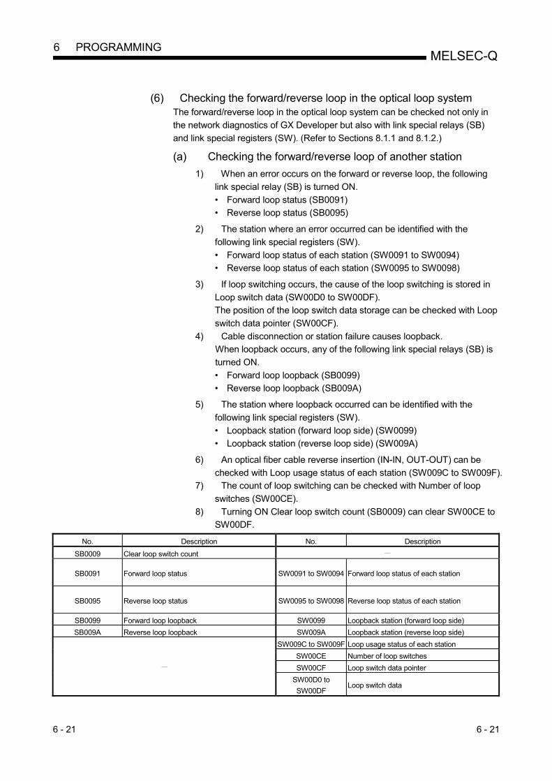
6 - 21 6 - 21
MELSEC-Q 6 PROGRAMMING
(6) Checking the forward/reverse loop in the optical loop system
The forward/reverse loop in the optical loop system can be checked not only in
the network diagnostics of GX Developer but also with link special relays (SB)
and link special registers (SW). (Refer to Sections 8.1.1 and 8.1.2.)
(a) Checking the forward/reverse loop of another station 1) When an error occurs on the forward or reverse loop, the following
link special relay (SB) is turned ON.
• Forward loop status (SB0091)
• Reverse loop status (SB0095) 2) The station where an error occurred can be identified with the
following link special registers (SW).
• Forward loop status of each station (SW0091 to SW0094)
• Reverse loop status of each station (SW0095 to SW0098) 3) If loop switching occurs, the cause of the loop switching is stored in
Loop switch data (SW00D0 to SW00DF).
The position of the loop switch data storage can be checked with Loop
switch data pointer (SW00CF).
4) Cable disconnection or station failure causes loopback.
When loopback occurs, any of the following link special relays (SB) is
turned ON.
• Forward loop loopback (SB0099)
• Reverse loop loopback (SB009A) 5) The station where loopback occurred can be identified with the
following link special registers (SW).
• Loopback station (forward loop side) (SW0099)
• Loopback station (reverse loop side) (SW009A) 6) An optical fiber cable reverse insertion (IN-IN, OUT-OUT) can be
checked with Loop usage status of each station (SW009C to SW009F).
7) The count of loop switching can be checked with Number of loop
switches (SW00CE).
8) Turning ON Clear loop switch count (SB0009) can clear SW00CE to
SW00DF. No. Description No. Description
SB0009 Clear loop switch count
SB0091 Forward loop status SW0091 to SW0094 Forward loop status of each station
SB0095 Reverse loop status SW0095 to SW0098 Reverse loop status of each station
SB0099 Forward loop loopback SW0099 Loopback station (forward loop side)
SB009A Reverse loop loopback SW009A Loopback station (reverse loop side)
SW009C to SW009F Loop usage status of each station
SW00CE Number of loop switches
SW00CF Loop switch data pointer
SW00D0 to
SW00DF Loop switch data

6 - 22 6 - 22
MELSEC-Q 6 PROGRAMMING
(b) Checking the forward/reverse loop of the host
1) When an error occurs on the forward or reverse loop, Host loop
status (SB0090) turns ON.
2) If loopback occurs, the cause of the loopback is stored in Loop switch
data (SW00D0 to SW00DF).
The position of the loop switch data storage can be checked with Loop
switch data pointer (SW00CF).
3) The loop status of the host can be checked with Loopback
information (SW0090).
4) The count of loop switching can be checked with Number of loop
switches (SW00CE).
5) Turning ON Clear loop switch count (SB0009) can clear SW00CE to
SW00DF.
No. Description No. Description
SB0009 Clear loop switch count
SB0090 Host loop status SW0090 Loopback information
SW00CE Number of loop switches
SW00CF Loop switch data pointer
SW00D0 to
SW00DF Loop switch data

6 - 23 6 - 23
MELSEC-Q 6 PROGRAMMING
(7) Checking the offline test status
The test status is checked through the LEDs on the network module, but it also
can be checked with link special relays (SB) and link special registers (SW).
(Refer to Sections 4.5 and 4.7.)
(a) Requesting side 1) When the offline test is instructed, Offline test instruction (SB00AC) is
turned ON.
An offline test item and a faulty station number are stored in Offline
test execution item/faulty station (requesting side) (SW00AC).
2) Upon completion of the offline test, Offline test completion (SB00AD)
is turned ON.
The offline test result is stored in Offline test result (requesting side)
(SW00AD).
No. Description No. Description
SB00AC Offline test instruction SW00AC Offline test execution item/faulty station
(requesting side)
SB00AD Offline test completion SW00AD Offline test result (requesting side)
(b) Responding side (the forward/reverse loop test only)
1) When a response is made to an offline test request from the
requesting side, Offline test response (SB00AE) is turned ON.
An offline test item is stored in Offline test execution item (responding
side) (SW00AE).
2) Upon completion of the offline test, Offline test response completion
(SB00AF) is turned ON.
The offline test result is stored in Offline test result (responding side)
(SW00AF).
No. Description No. Description
SB00AE Offline test response SW00AE Offline test execution item (responding
side)
SB00AF Offline test response completion SW00AF Offline test result (responding side)

6 - 24 6 - 24
MELSEC-Q 6 PROGRAMMING
(8) Checking the online test status
The test status is checked through LED of the network module main frame, but it
also can be checked with link special relay (SB) and link special register (SW).
(Refer to Section 4.8.)
(a) Requesting side 1) When the online test is instructed, Online test instruction (SB00A8) is
turned ON.
An online test item and a faulty station number are stored in Online
test execution item/faulty station (requesting side) (SW00A8).
2) Upon completion of the online test, Online test completion (SB00A9)
is turned ON.
The online test result is stored in Online test result (requesting side)
(SW00A9).
No. Description No. Description
SB00A8 Online test instruction SW00A8 Online test execution item/faulty station
(requesting side)
SB00A9 Online test completion SW00A9 Online test result (requesting side)
(b) Responding side
1) When a response is made to an online test request from the
requesting side, Online test response (SB00AA) is turned ON.
An online test item is stored in Online test execution item (responding
side) (SW00AA).
2) Upon completion of the online test, Online test response completion
(SB00AB) is turned ON.
The online test result is stored in Online test result (responding side)
(SW00AB).
No. Description No. Description
SB00AA Online test response SW00AA Online test execution item (responding
side)
SB00AB Online test response completion SW00AB Online test result (responding side)
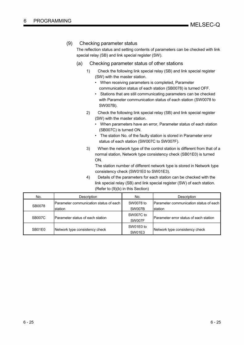
6 - 25 6 - 25
MELSEC-Q 6 PROGRAMMING
(9) Checking parameter status
The reflection status and setting contents of parameters can be checked with link
special relay (SB) and link special register (SW).
(a) Checking parameter status of other stations
1) Check the following link special relay (SB) and link special register
(SW) with the master station.
• When receiving parameters is completed, Parameter
communication status of each station (SB0078) is turned OFF.
• Stations that are still communicating parameters can be checked
with Parameter communication status of each station (SW0078 to
SW007B). 2) Check the following link special relay (SB) and link special register
(SW) with the master station.
• When parameters have an error, Parameter status of each station
(SB007C) is turned ON.
• The station No. of the faulty station is stored in Parameter error
status of each station (SW007C to SW007F). 3) When the network type of the control station is different from that of a
normal station, Network type consistency check (SB01E0) is turned
ON.
The station number of different network type is stored in Network type
consistency check (SW01E0 to SW01E3).
4) Details of the parameters for each station can be checked with the
link special relay (SB) and link special register (SW) of each station.
(Refer to (9)(b) in this Section)
No. Description No. Description
SB0078 Parameter communication status of each
station
SW0078 to
SW007B
Parameter communication status of each
station
SB007C Parameter status of each station SW007C to
SW007F Parameter error status of each station
SB01E0 Network type consistency check SW01E0 to
SW01E3 Network type consistency check
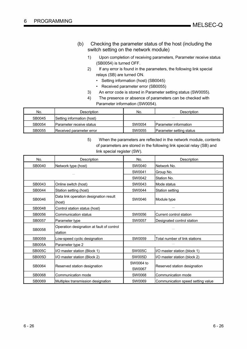
6 - 26 6 - 26
MELSEC-Q 6 PROGRAMMING
(b) Checking the parameter status of the host (including the
switch setting on the network module)
1) Upon completion of receiving parameters, Parameter receive status
(SB0054) is turned OFF.
2) If any error is found in the parameters, the following link special
relays (SB) are turned ON.
• Setting information (host) (SB0045)
• Received parameter error (SB0055)
3) An error code is stored in Parameter setting status (SW0055).
4) The presence or absence of parameters can be checked with
Parameter information (SW0054).
No. Description No. Description
SB0045 Setting information (host)
SB0054 Parameter receive status SW0054 Parameter information
SB0055 Received parameter error SW0055 Parameter setting status
5) When the parameters are reflected in the network module, contents
of parameters are stored in the following link special relay (SB) and
link special register (SW).
No. Description No. Description
SB0040 Network type (host) SW0040 Network No.
SW0041 Group No.
SW0042 Station No.
SB0043 Online switch (host) SW0043 Mode status
SB0044 Station setting (host) SW0044 Station setting
SB0046 Data link operation designation result
(host) SW0046 Module type
SB0048 Control station status (host)
SB0056 Communication status SW0056 Current control station
SB0057 Parameter type SW0057 Designated control station
SB0058 Operation designation at fault of control
station
SB0059 Low-speed cyclic designation SW0059 Total number of link stations
SB005A Parameter type 2
SB005C I/O master station (Block 1) SW005C I/O master station (block 1)
SB005D I/O master station (Block 2) SW005D I/O master station (block 2)
SB0064 Reserved station designation SW0064 to
SW0067 Reserved station designation
SB0068 Communication mode SW0068 Communication mode
SB0069 Multiplex transmission designation SW0069 Communication speed setting value
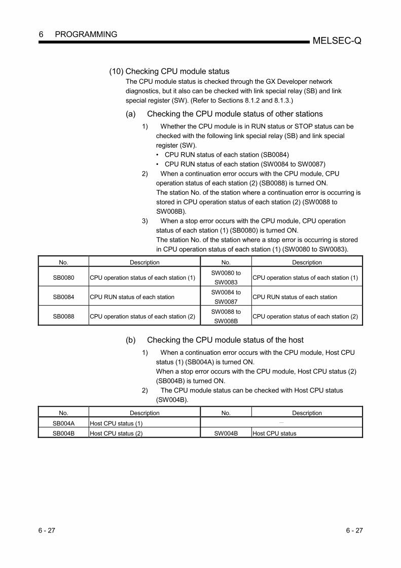
6 - 27 6 - 27
MELSEC-Q 6 PROGRAMMING
(10) Checking CPU module status
The CPU module status is checked through the GX Developer network
diagnostics, but it also can be checked with link special relay (SB) and link
special register (SW). (Refer to Sections 8.1.2 and 8.1.3.)
(a) Checking the CPU module status of other stations 1) Whether the CPU module is in RUN status or STOP status can be
checked with the following link special relay (SB) and link special
register (SW).
• CPU RUN status of each station (SB0084)
• CPU RUN status of each station (SW0084 to SW0087)
2) When a continuation error occurs with the CPU module, CPU
operation status of each station (2) (SB0088) is turned ON.
The station No. of the station where a continuation error is occurring is
stored in CPU operation status of each station (2) (SW0088 to
SW008B).
3) When a stop error occurs with the CPU module, CPU operation
status of each station (1) (SB0080) is turned ON.
The station No. of the station where a stop error is occurring is stored
in CPU operation status of each station (1) (SW0080 to SW0083).
No. Description No. Description
SB0080 CPU operation status of each station (1) SW0080 to
SW0083 CPU operation status of each station (1)
SB0084 CPU RUN status of each station SW0084 to
SW0087 CPU RUN status of each station
SB0088 CPU operation status of each station (2) SW0088 to
SW008B CPU operation status of each station (2)
(b) Checking the CPU module status of the host
1) When a continuation error occurs with the CPU module, Host CPU
status (1) (SB004A) is turned ON.
When a stop error occurs with the CPU module, Host CPU status (2)
(SB004B) is turned ON.
2) The CPU module status can be checked with Host CPU status
(SW004B).
No. Description No. Description
SB004A Host CPU status (1)
SB004B Host CPU status (2) SW004B Host CPU status

6 - 28 6 - 28
MELSEC-Q 6 PROGRAMMING
(11) Checking the multiplex transmission status
The multiplex transmission status is checked through the GX Developer network
diagnostics, but it also can be checked with link special relay (SB) and link
special register (SW). (Refer to Section 8.1.3.) 1) If the "With multiplex transmission" box is checked in the
supplementary settings of common parameters, Multiplex transmission
designation (SB0069) is turned ON.
2) An execution of the multiplex transmission function turns ON
Multiplex transmission status (SB006A).
3) Data showing the forward and reverse loop states during multiplex
transmission are stored in the following link special registers (SW).
• Multiplex transmission status (1) (SW00B0 to SW00B3)
• Multiplex transmission status (2) (SW00B4 to SW00B7)
No. Description No. Description
SB0069 Multiplex transmission designation
SB006A Multiplex transmission status
SW00B0 to
SW00B3 Multiplex transmission status (1)
SW00B4 to
SW00B7 Multiplex transmission status (2)
(12) Checking the redundant system status
The redundant system status can be checked with link special relays (SB) and
link special registers (SW).
(a) Checking the redundant system support and setting
1) When the network module supports the redundant system, Host
station's redundant function support information (SB0041) is ON.
2) To set the time taken from detection of a data link stop until system
switching is requested in the redundant system, set a time value in
System switching monitoring time setting (SW0018).
3) If System switching monitoring time setting valid flag (SB0018) is
turned ON, System switching monitoring time setting (SW0018) is
enabled.
No. Description No. Description
SB0018 System switching monitoring time setting
valid flag SW0018 System switching monitoring time setting
SB0041 Host station's redundant function support
information

6 - 29 6 - 29
MELSEC-Q 6 PROGRAMMING
(b) Checking the redundant system status
1) When a Redundant CPU in separate mode exists, Redundant
system status (1) (SB01F4) is ON.
The operation mode of a redundant CPU can be checked in
Redundant system status (1) (SW01F4 to SW01F7).
2) When any pairing setting exists, Redundant system status (2)
(SB01F8) is ON.
Stations for which the pairing setting is done can be checked in
Redundant system status (2) (SW01F8 to SW01FB).
3) When a station operating on the standby system exists, Redundant
system status (3) (SB01FC) is ON.
The control or standby status of a Redundant CPU can be confirmed
with Redundant system status (3) (SW01FC to SW01FF).
No. Description No. Description
SB01F4 Redundant system status (1) SW01F4 to
SW01F7 Redundant system status (1)
SB01F8 Redundant system status (2) SW01F8 to
SW01FB Redundant system status (2)
SB01FC Redundant system status (3) SW01FC to
SW01FF Redundant system status (3)

6 - 30 6 - 30
MELSEC-Q 6 PROGRAMMING
(13) Setting a link dedicated instruction and checking the processing
result With link special relays (SB) and link special registers (SW), link dedicated
instructions can be set and the processing results can be checked. 1) Link dedicated instructions can be set with the following link special
registers (SW).
• Logical channel setting (SW0008 to SW000F)
• Number of retries (SW001C)
• Retry interval (SW001D)
• Number of gates (SW001E)
2) When data are stored in the host's channel area, the corresponding
RECV execution request flag (SB00A0 to SB00A7) turns ON.
Upon completion of the RECV instruction, the RECV instruction
execution request flag (SB00A0 to SB00A7) turns OFF.
3) Processing results of link dedicated instructions can be checked with
Send/receive instruction processing results (SW0031 to SW003F). No. Description No. Description
SW0008 Logical channel setting (channel 1)
SW0009 Logical channel setting (channel 2)
SW000A Logical channel setting (channel 3)
SW000B Logical channel setting (channel 4)
SW000C Logical channel setting (channel 5)
SW000D Logical channel setting (channel 6)
SW000E Logical channel setting (channel 7)
SW000F Logical channel setting (channel 8)
SW001C Number of retries
SW001D Retry interval
SW001E Number of gates
SW0031 ZNRD instruction processing result
Send/receive instruction (1) processing result
SW0033 ZNWR instruction processing result
Send/receive instruction (2) processing result
SW0035 Send/receive instruction (3) processing result
SW0037 Send/receive instruction (4) processing result
SW0039 Send/receive instruction (5) processing result
SW003B Send/receive instruction (6) processing result
SW003D Send/receive instruction (7) processing result
SW003F Send/receive instruction (8) processing result
SB00A0 RECV instruction execution request flag (1)
SB00A1 RECV instruction execution request flag (2)
SB00A2 RECV instruction execution request flag (3)
SB00A3 RECV instruction execution request flag (4)
SB00A4 RECV instruction execution request flag (5)
SB00A5 RECV instruction execution request flag (6)
SB00A6 RECV instruction execution request flag (7)
SB00A7 RECV instruction execution request flag (8)

6 - 31 6 - 31
MELSEC-Q 6 PROGRAMMING
(14) Checking the communication status between the network module
and CPU module The communication status between the network module and CPU module can be
checked by using the link special relay (SB) or link special register (SW). (a) Checking the error details
1) When an error occurs during the communications between the
network module and CPU module, Module status (SB0020) is turned
ON.
2) An error code is stored in Module status (SW0020).
No. Description No. Description
SB0020 Module status SW0020 Module status
(b) Checking the module type
The module type data are stored in the following link special relays (SB)
and link special registers (SW).
No. Description No. Description
SB008D Module type of each station
SW00E8 to
SW00EB Module type of each station
(c) Checking the external power supply status
1) When external power is supplied, External power supply information
(SB008C) is turned ON.
The status of the host can be also checked with Power supply status
of host (SB0042).
2) Station numbers of the stations to which external power is supplied
are stored in Power supply status of each station (SW008C to
SW008F).
No. Description No. Description
SB0042 Power supply status of host
SB008C External power supply information SW008C to
SW008F Power supply status of each station
(d) Checking the current communication speed
When the twisted bus system is configured, current communication speed
is stored in the following special register (SW).
No. Description No. Description
SW006A Current communication speed value

7 - 1 7 - 1
MELSEC-Q 7 APPLICATION FUNCTIONS
7 APPLICATION FUNCTIONS When applying any of the program examples introduced in this chapter to the actual system, verify the applicability and confirm that no problems will occur in the system control.
Communication using LX/LY
RAS function Automatic return function
Control station switch function
Control station return control function
Loopback function (optical loop system)
Station detach function (coaxial bus system,
and twisted bus system)
Transient transmission enabled even at CPU
module error
Checking transient transmission abnormal
detection time
Diagnostic function
Communication using LB/LWBasic
functions
Cyclic transmission function
(Periodical communication)
Chapter 3
Chapter 7
Starting interrupt sequence program
Multiplex transmission function (optical loop system)
Stopping/restarting of cyclic transmission and stopping link refresh (network test)
Increasing number of send points by installing multiple modules with the same network number
Low-speed cyclic transmission
Inter-link data transfer function
Routing function
Group function
Message sending function using logical channel numbers
Data sending/receiving (SEND/RECV)
Other station word device read/write (READ/SREAD/WRITE/SWRITE)
Other station transient request (REQ)
Other station word device read/write (ZNRD/ZNWR)
Direct access to link devicesApplication functions
Cyclic transmission function
(Periodical communication)
Communication functionTransient transmission function
(Non-periodical communication)
Clock setting to stations on a network using GX Developer
Simple dual-structured network
Section 3.2.1 (1)
Section 3.2.1 (2)
Section 3.2.2 (1)
Section 3.2.2 (2)
Section 3.2.2 (3)
Section 3.2.2 (4)
Section 3.2.2 (6)
Section 3.2.2 (7)
Section 3.2.2 (8)
Section 3.2.2 (9)
Section 7.1
Section 7.3
Section 7.2
Section 7.4.6
Message receiving "1 scan completion" (RECVS) Section 7.5
Section 7.6
Section 7.7
Section 7.8
Section 7.9
Section 8.1
Remote RUN/Remote STOP (RRUN/RSTOP)
Reading and writing other station CPU module's clock data (RTMRD/RTMWR)
Prevention of station failure by using external
power supply (Optical loop system) Section 3.2.2 (5)
Redundant system function Pairing setting
Redundant settings
System switching request function
Section 7.10.3
Section 7.10.4
Section 7.10.5
Section 7.4.2
Section 7.4.3
Section 7.4.4
Section 7.4.5 (1)
Section 7.4.5 (2)
Section 7.4.5 (3)
Section 7.4.5 (4)
Section 7.4.5 (5)
Section 7.4.5 (6)
Section 7.4.1
Network diagnostic (network monitor)
7

7 - 2 7 - 2
MELSEC-Q 7 APPLICATION FUNCTIONS
7.1 Direct Access to the Link Devices
The link devices (LB, LW, LX, LY, SB, SW) of the network module can be directly read
or written by sequence programs regardless of the link refresh of the CPU module.
With direct access, link devices that are not set within the range of the link refresh with
the refresh parameters can also be read or written.
CPU Network module
Designate the link device to be directly accessed with "J \ ."
MOVK20J1\W100
=J1\W200 K300
J1\B10
J1\B100LB
To other station
From other station
LW
J1\X1000
LYJ1\Y1000
LX
LX
LY
1:1 communication with other station
To other station
From other station
POINT
(1) The direct access of the link devices LX/LY is limited to the communication
with the block I/O master station set with the communication parameters. By
limiting the communication, data cannot be shared among multiple stations,
such as LB/LW, but 1:1 communication between predefined stations is
allowed.
(2) Remove any infrequently used link devices from the link refresh range, and
directly read or write them using link direct devices.
This reduces the points of the link refresh to the CPU module, resulting in a
shorter link refresh time.
(3) Since the link direct device reads or writes data directly to the link devices of
the network module at the time of the instruction execution, the transmission
delay time can be reduced.
7

7 - 3 7 - 3
MELSEC-Q 7 APPLICATION FUNCTIONS
(1) How to specify J \
Specify the network number and link device to be read or written.
Link relay · · · · · · · · · · · · · · · · · · · · · · · · ·
Link register · · · · · · · · · · · · · · · · · · · · · · ·
Link input · · · · · · · · · · · · · · · · · · · · · · · · ·
Link output · · · · · · · · · · · · · · · · · · · · · · · ·
Link special relay · · · · · · · · · · · · · · · · · · ·
Link special register · · · · · · · · · · · · · · · · ·
Network No. · · · · · · · · · · · · · · · · · · · · · · ·
J \
B0 to 3FFF
W0 to 3FFF
X0 to 1FFF
Y0 to 1FFF
SB0 to 1FF
SW0 to 1FF
1 to 239
POINT
When specifying the link direct device by a network No., a module that is mounted
on the slot with the smallest number in the base unit is targeted.
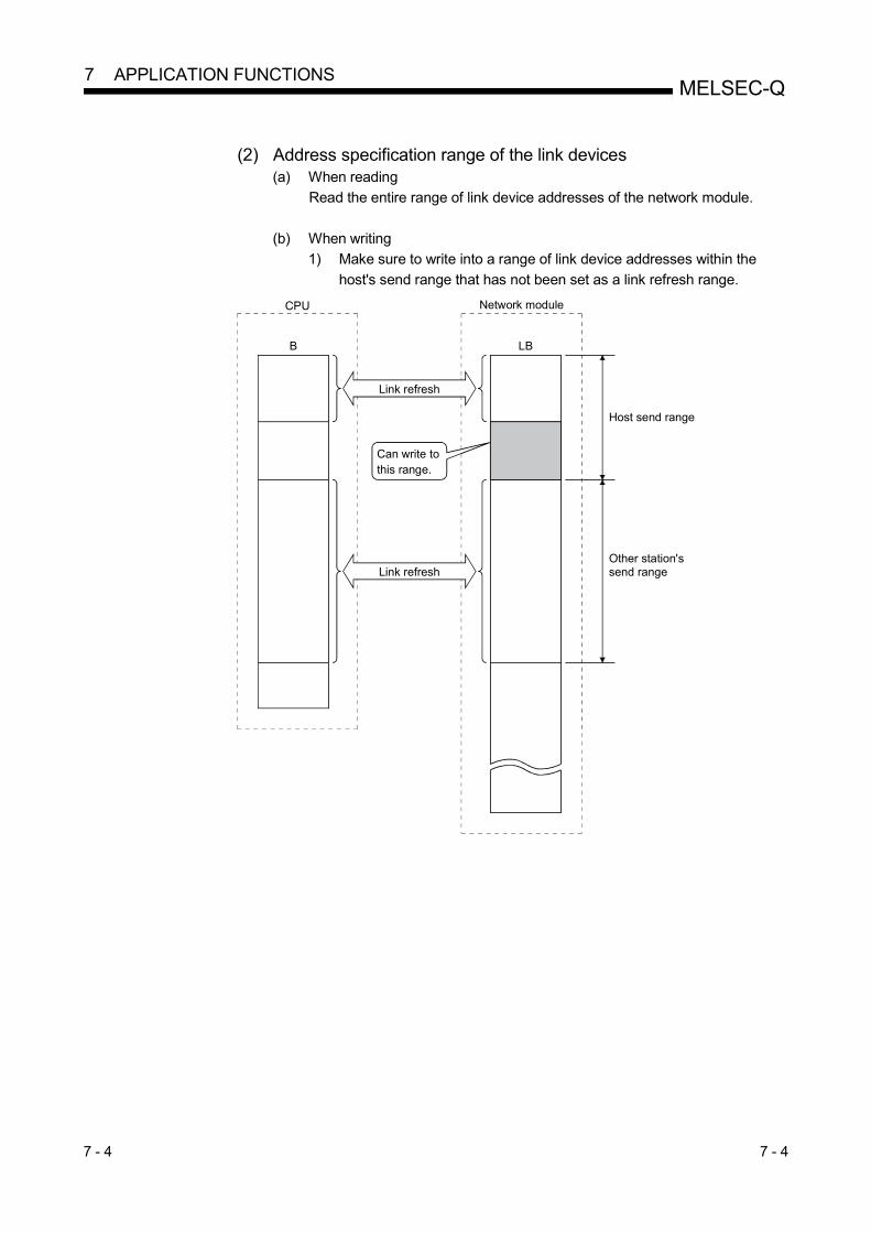
7 - 4 7 - 4
MELSEC-Q 7 APPLICATION FUNCTIONS
(2) Address specification range of the link devices
(a) When reading
Read the entire range of link device addresses of the network module.
(b) When writing
1) Make sure to write into a range of link device addresses within the
host's send range that has not been set as a link refresh range.
LB
Network module
B
Link refresh
CPU
Can write to this range.
Link refresh
Host send range
Other station's send range

7 - 5 7 - 5
MELSEC-Q 7 APPLICATION FUNCTIONS
2) If an address in the link refresh range is specified, data is written to
that address when the instruction is executed, but the link device of the
network module is overwritten by the link device data of the CPU
module by the link refresh.
Make sure to write the same data to the link device of the CPU module
as well when writing by direct access (same for B, Y, SB and SW).
CPU
20 to 300
LW
Network module
100
300
W
100
MOV K20 J1\W100
Link refresh
CPU
20
LW
100
20
W
100
MOV K20 J1\W100
MOV K20 W100
Network module
Link refresh
(3) Differences from the link refresh The following table shows how the direct access to link devices is different from
the link refresh.
For details, refer to the User's Manual (Function Explanation, Program
Fundamentals) of the CPU module used. Access method
Item Link refresh Direct access
Number of steps 1 step 2 steps
Processing speed (LD BO – | | –) 1 High speed (0.034 µs) Low-speed (several 10 µs)
Data reliability Per station 2 2-word units (32 bits) 3
1: For Q02HCPU 2: When the parameter of the station-based block data assurance is enabled. 3: When the 32-bit data assurance conditions are satisfied.

7 - 6 7 - 6
MELSEC-Q 7 APPLICATION FUNCTIONS
7.2 Inter-Link Data Transfer Function (High Performance model QCPU, Process CPU,
Redundant CPU, and Universal model QCPU) This function transfers link data to different networks in a batch mode using parameters when multiple networks are connected to one programmable controller. Interlink transfer is executable between CC-Link IE Controller Network, CC-Link IE Field Network and MELSECNET/H.
POINT Only one network module can be accepted on the Basic model QCPU, Q00UJCPU, Q00UCPU, Q01UCPU, and safety CPU. Hence, the inter-link data transfer function cannot be used.
(1) Inter-link data transfer function
(a) By using this function, it becomes unnecessary to transfer data between networks with the sequence programs using the MOV instruction, etc.
(b) It is necessary to set the "Interlink transmission parameters" in order to execute the inter-link data transfer function.
(c) The devices whose data can be transferred by the inter-link data transfer are the link relay (LB) and link register (LW) of each network module (data link module). The data of the link input (LX) and link output (LY) devices cannot be transferred between data links.
(d) When sending data, set the device range within the host's send range of the transfer from network module.
(e) When sending one batch of data to multiple networks, the same numbers can be set for the device range of the transfer source. For example, when transferring the data received from network number 1 (module 1) to both network number 2 (module 2) and number 3 (module 3), the same transfer from device range can be set for the interlink transmission parameters, "Module 1 2" and "Module 1 3."
The figure below shows an example of transfer between network number 1 and network number 2. Set the "Interlink transmission parameters" for the programmable controller that serves as the relay station. In this example, the data of B0, which was turned on by station's 1MP1 of network number 1, is received by relay station 1NS3 of network number 1. Then, the data is transferred to the range (LB1000) assigned for relay station 2MP1 of network number 2. Stations 2NS2 and 2NS3 of network number 2 can thus check the on/off status of B0 of station 1MP1 of network number 1 through the data of B1000.
Network No. 1
1MP1 1NS2 2NS2 2NS3
Network No. 2
B0B200
B1300
B1000
B200 B1000
B1300
B0B280
B281
The transfer to device of the intermediate station does not turn on/off.
0
3FF
100
200
0
21F
1000
13FF
1FFF
2NS2
2NS3
1000
101F
1300
1020
103F
B
Q25HCPU
LB
1NS3
LB
2MP1
1F
11F
1MP1
1NS2
131F
13FF
2MP1(host)
to
to
1NS3(host)
to
to
to
toto
to

7 - 7 7 - 7
MELSEC-Q 7 APPLICATION FUNCTIONS
(2) Interlink transmission parameters
When transferring data to other network, up to 64 transfer ranges can be set
between the network modules. Note that, when data from a given device range is
transferred to multiple network numbers, as many setting ranges must be set as
the number of transfer to networks.
[Setting example]
Module 1 (0H to 3FH) Module 2 (1000H to 103FH)
Module 2 (1100H to 115FH) Module 1 (100H to 15FH)
0
FF100
LB LB
10FF1100
1000
1FF
0
11FF
0 to 3F
100 to 15F
1000 to 103FMake sure to set the transfer to within the host's (control station) send range.
1100 to 115F
MNET/H (control station)module 1
MNET/H (normal station)module 2
to
to
to
to
Make sure to set the transfer to within the host's (normal station) send range.
Transfer from Module1: MNET/H mode (Control station)
Transfer to Module2: MNET/H mode (Normal station)
Transfer to Module1: MNET/H mode (Control station)
Transfer from Module2: MNET/H mode (Normal station)
Click the button.

7 - 8 7 - 8
MELSEC-Q 7 APPLICATION FUNCTIONS
Precautions
1) Do not set the Transfer to device range of the network module within the
refresh range of the network. Otherwise, the correct data cannot be sent to
other stations.
Network module 1CPU
Refresh range
Network module 2
Refresh range
Transferto
Transferfrom
2) The transfer data is sent to the transfer to network via the network module; it is
not stored in the transfer to device range of the network module.
When using the transfer data in the relay station, the transfer to data must be
transferred to the device on the CPU side by link refreshing. POINT
When it is necessary to set 65 or more transfer ranges for the inter-link data
transfer function, the data must be transferred from the transfer from to the
destination in the sequence programs using the MOV instruction, etc.
(3) Available inter-link data transfer stations
As shown in the table below, the control stations and normal stations are
available. Transfer to
Transfer from
MELSECNET/H
Control station Normal station Standby station
MELSEC
NET/H
Control station
Normal station
Standby station : Available : Not available

7 - 9 7 - 9
MELSEC-Q 7 APPLICATION FUNCTIONS
7.3 Low-Speed Cyclic Transmission Function (High Performance model QCPU, Process
CPU, Redundant CPU, and Universal model QCPU) The low-speed cyclic transmission function is convenient when sending data that does not require high-speed transfer to other stations in a batch mode using the link devices (LB/LW). The performance of the low-speed cyclic transmission function is almost the same as that of the transient transmission function. For details of the performance, refer to Section 7.4. A station can transmit data only once in a single link scan. To send data from multiple stations concurrently, the link scan time must be longer than the total transmission time for all the sending stations. In the low-speed cyclic transmission, send range for each station is set with the common parameters of the control station.
Low-speed cyclic send range for each station
The sending to other stations can be activated by three methods: 1) Transmit data of one station in 1 scan (default), 2) Fixed term cycle interval setting, and 3) System times. These methods can be specified through by the supplementary settings, and only one of them can be selected. The screen shown below is the supplemental screen where the activation method can be selected.
1)
2)
3)
POINT The Basic model QCPU, Q00UJCPU, Q00UCPU, Q01UCPU, and safety CPU does not support the low-speed cyclic transmission function.

7 - 10 7 - 10
MELSEC-Q 7 APPLICATION FUNCTIONS
7.3.1 Send range settings
Each station's send range of link devices (low-speed LB, low-speed LW) is assigned to the extended area (2000 to 3FFF) in 16-point units for LB (start : 0 to end
F) and in one-point units for LW. Each station's send range can also be assigned using a random station number assignment sequence. The B/W device numbers on the CPU side that correspond to the extended area are not assigned. (1) Device range
MELSECNET/H LB
CPU B
0H 2000H3FFFH
(8192) (16383)
Normal cyclic transmission area Extended function area
(2) Screen settings
On the following screen that is displayed by clicking the
Network range assignment button, 768 points are assigned to the send range
for each station (low-speed LB, low-speed LW).
Send points (LB/16-point, LW/1-point units)
Send range (2000 to 3FFF)
POINT (1) To use 2-word (32-bit) data, set appropriate send points and send range that
satisfy the conditions for the 32-bit data assurance. For details, refer to Section 6.2.1.
(2) The device points (B, W) of the CPU module can be increased by changing the PLC parameters (8 k to 16 k). However, there are restrictions for the device points, such as that the total must be less than 28.8 k words.
(3) Link devices in the Extended function area (2000H to 3FFFH) can be also used for normal cyclic transmission (when link devices of 8193 points or more are used for normal cyclic transmission). For low-speed transmission, use link devices in the Extended function area, which are not used for normal cyclic transmission.
(4) The total of the send ranges per station must not exceed 2000 bytes in the low-speed cyclic transmission. (The send range for the normal cyclic transmission is not included.)
(5) LX and LY cannot be set as link devices for low-speed cyclic transmissions.

7 - 11 7 - 11
MELSEC-Q 7 APPLICATION FUNCTIONS
7.3.2 Send timing
The low-speed cyclic transmission is executed separately from the normal cyclic
transmission. This section describes the setting, processing interval and link cycle of
the low-speed cyclic transmission.
(1) Transmission setting
The link cycle of the low-speed cyclic transmission varies depending on its
transmission setting.
The setting can be made at "Specification of low speed cyclic transmission" on
"Supplementary setting". (Refer to Section 7.3.3.)
The following lists the setting options.
Setting item Description
Transmit data of one station
in 1 link scan
Low-speed cyclic data of max. one station are sent during
one link scan of normal cyclic transmission.
Fixed term cycle interval
setting
Low-speed cyclic data are sent at a specified time
interval. 1
System times Low-speed cyclic data are sent at a specified time. 1
1: Maximum no. of stations capable of sending data during 1 link scan of
normal cyclic transmission varies depending on the "Maximum no. of
transients in 1 scan" setting.
Refer to Section 7.4.1 for the "Maximum no. of transients in 1 scan" setting.
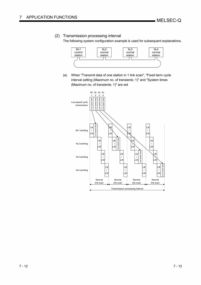
7 - 12 7 - 12
MELSEC-Q 7 APPLICATION FUNCTIONS
(2) Transmission processing interval
The following system configuration example is used for subsequent explanations.
NS4
normalstation
NS3normalstation
NS2normalstation
MP1control station
(a) When "Transmit data of one station in 1 link scan", "Fixed term cycle
interval setting (Maximum no. of transients: 1)" and "System times
(Maximum no. of transients: 1)" are set
LB/
LW
LB/
LW
LB/
LW
LB/
LW
LB/
LW
LB/
LW
LB/
LW
LB/
LW
LB/
LW
MP1 sending
NS2 sending
NS3 sending
NS4 sending
Low-speed cyclic transmission
Normal link scan
Low
-spe
ed d
ata
MP
1NS
2NS
3NS
4Lo
w-s
peed
dat
a
Low
-spe
ed d
ata
Low
-spe
ed d
ata
LB/
LW
Low
-spe
ed d
ata
LB/
LW
Low
-spe
ed d
ata
LB/
LW
Normal link scan
Normal link scan
Normal link scan
LB/
LW
Low
-spe
ed d
ata
LB/
LW
LB/
LW
LB/
LW
Low
-spe
ed d
ata
Transmission processing interval

7 - 13 7 - 13
MELSEC-Q 7 APPLICATION FUNCTIONS
(b) When "Fixed term cycle interval (Maximum no. of transients: 2)" and
"System times (Maximum no. of transients: 2)" are set
MP1 sending
NS2 sending
NS3 sending
NS4 sending
Normal link scan
LB/
LW
Low
-spe
ed d
ata
Transmission processing interval
LB/
LWL
ow-s
peed
dat
a
LB/
LW
LB
/LW
LB/
LW
Low
-spe
ed d
ata
LB
/LW
Low
-spe
ed d
ata
LB/
LW
Low
-spe
ed d
ata
LB/
LW
LB/
LW
Normal link scan
Low-speed cyclic transmission
Low
-spe
ed d
ata
MP
1NS
2NS
3NS
4
Low
-spe
ed d
ata
Low
-spe
ed d
ata
Low
-spe
ed d
ata
(3) Link cycle Link cycle examples of the low-speed transmission are as shown below.
(a) When "Transmit data of one station in 1 link scan" is set
Normallink scan
Transmission processinginterval in (2)
Link cycle
(b) When "Fixed term cycle interval setting" is set
Transmission processing
interval in (2)Waiting time
Link cycle (Fixed time interval)
(c) When "System times" is set
Transmission processing
interval in (2)
Specified time

7 - 14 7 - 14
MELSEC-Q 7 APPLICATION FUNCTIONS
7.3.3 Startup
(1) Sending of data for one station per link scan (default) The low-speed cyclic data for a maximum of one station is sent in one link scan
of the normal cyclic transmission.
[Setting method]
1) Click ( ) [Transmit data of one station in 1 scan] to select.
POINT
The fastest link scan time in the low-speed cyclic transmission can be calculated by
the following equation:
LSL = LS number of stations + LS
= LS (number of stations + 1)
LSL : The fastest link scan time in the low-speed cyclic transmission
LS : Normal link scan time
(2) Fixed term cycle interval setting
The low-speed cyclic data is sent in the link cycle of the specified time frequency.
Valid setting frequency: 1 to 65535 s (18 h, 12 min and 15 s)
[Setting method]
1) Click ( ) [Fixed interval cycle setting] to select.
2) Set the time in seconds (the screen shows a value of 600).

7 - 15 7 - 15
MELSEC-Q 7 APPLICATION FUNCTIONS
(3) System timer interval
The low-speed cyclic data is sent in the link cycle at the specified time.
By omitting year, month, and date, the low-speed cycle transmission can be
activated yearly (or monthly, or daily). Hour, minute and second cannot be
omitted.
Setting points: 1 to 8 points
[Setting method]
1) Click ( ) [System times] to select.
2) Set year, month, date, hour, minute and second to the specified time.
In the following screen example:
Points 1 to 3 : By omitting year, month and date, data is sent every
day at the specified time.
Points 4 and 5 : By omitting year and month, data is sent at the
specified time monthly.
Point 6 : By omitting the year, data is sent at the specified time
every year.
Points 7 to 8 : Data is sent only once at the specified time.
POINT
(1) The system timer operates based on the host's clock. If used without
matching the clocks on the sending station and receiving station, there may
be a time gap between the stations.
(2) When handling multiple data without the station-based block data assurance
function, new and old data may coexist. Apply interlocks in the programs
(refer to Section 6.2.3).
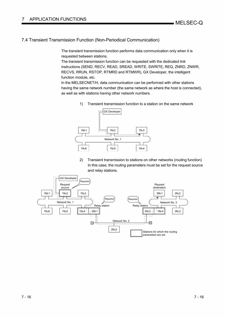
7 - 16 7 - 16
MELSEC-Q 7 APPLICATION FUNCTIONS
7.4 Transient Transmission Function (Non-Periodical Communication)
The transient transmission function performs data communication only when it is
requested between stations.
The transient transmission function can be requested with the dedicated link
instructions (SEND, RECV, READ, SREAD, WRITE, SWRITE, REQ, ZNRD, ZNWR,
RECVS, RRUN, RSTOP, RTMRD and RTMWR), GX Developer, the intelligent
function module, etc.
In the MELSECNET/H, data communication can be performed with other stations
having the same network number (the same network as where the host is connected),
as well as with stations having other network numbers.
1) Transient transmission function to a station on the same network
GX Developer
1NS21MP1
1NS51NS6
1NS3
1NS4
Network No. 1
2) Transient transmission to stations on other networks (routing function)
In this case, the routing parameters must be set for the request source
and relay stations.
GX Developer
1MP1 1NS2 1NS3
1NS6 1NS5
Network No. 1
Requestsource
1NS4 2MP1
Relay station
3MP1
Network No. 3
Requestdestination
3NS42NS3
3NS2
3NS3
2NS2
Network No. 2
Stations for which the routing parameters are set
Required
Required Required
Relay station

7 - 17 7 - 17
MELSEC-Q 7 APPLICATION FUNCTIONS
7.4.1 Communication function
(1) Parameter settings Set the execution conditions for the transient transmission with the parameters
listed below.
In the default settings, both the number of transients that one network can
execute in one link scan ([Maximum no. of transients in 1 scan]) and the number
of transients that one station can execute in one link scan ([Maximum no. of
transients in one station]) are set to 2 times. Change the number of transients
that can be executed in a link scan as necessary (refer to POINT on the bottom
of this page).
Setting value
Setting item Valid setting times Default setting
Maximum no. of transients in 1 scan 1 to 255 times Twice
Maximum no. of transients in one station 1 to 10 times Twice
[Screen display]
Click
Transient settingClick
Network range assignment
Supplementary settings
POINT
(1) By increasing the number of transients, multiple transient instructions can be
executed at the same time (in one link scan).
(2) If the number of transients is increased and the transient request was issued in each station at the same time, the link scan time becomes temporarily
longer and the cyclic transmission is also affected. Do no set unnecessarily
large values. (3) When the transient transmission and the low-speed cyclic transmission are
used at the same time, these transient setting parameters limit the total
number of transient and low-speed cyclic transmissions.

7 - 18 7 - 18
MELSEC-Q 7 APPLICATION FUNCTIONS
(2) Transient transmission range
In a multiple network system of the MELSECNET/H, communication can be
performed with stations in a maximum of eight networks by setting the routing
parameters described in Section 7.4.2. The following figure illustrates the transient transmission range using an example
where the destinations are limited to eight networks.
POINT
(1) Since only one network module can be installed with the Basic model QCPU, Q00UJCPU, Q00UCPU, Q01UCPU, and safety CPU, it cannot be used as a
relay station.
(2) For access via a redundant system, the routing parameters of the request source or relay station(s) must be changed with the RTWRITE instruction if
system switching occurs in the redundant system.
For details, refer to Section 7.10.8.
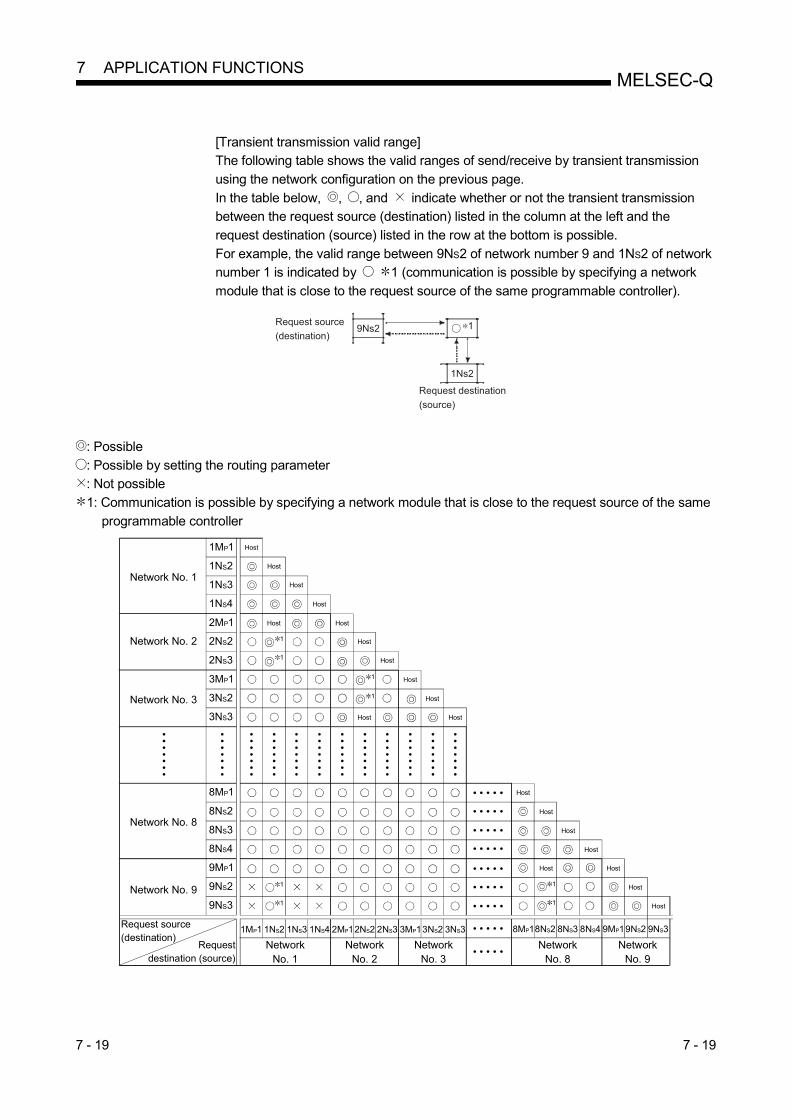
7 - 19 7 - 19
MELSEC-Q 7 APPLICATION FUNCTIONS
[Transient transmission valid range] The following table shows the valid ranges of send/receive by transient transmission
using the network configuration on the previous page.
In the table below, , , and indicate whether or not the transient transmission between the request source (destination) listed in the column at the left and the
request destination (source) listed in the row at the bottom is possible.
For example, the valid range between 9NS2 of network number 9 and 1NS2 of network number 1 is indicated by 1 (communication is possible by specifying a network
module that is close to the request source of the same programmable controller).
Request source 9Ns2
1Ns2
1(destination)
Request destination
(source)
: Possible
: Possible by setting the routing parameter : Not possible
1: Communication is possible by specifying a network module that is close to the request source of the same
programmable controller
Network No. 1
Network No. 2
Network No. 3
Network No. 9
Network No. 8
1MP1
1NS2
1NS3
1NS4
2MP1
2NS2
2NS3
3MP1
3NS2
3NS3
8MP1
8NS2
8NS3
8NS4
9MP1
9NS2
9NS3
Host
Request source(destination)
Request destination (source)
1MP1 1NS2 1NS3 1NS4 2MP12NS2 2NS3 3MP13NS2 3NS3
NetworkNo. 1
8MP18NS2 8NS3 8NS4 9MP19NS2 9NS3
NetworkNo. 2
1
1
1
1
1
1
1
1
• • • • •
• • • • •
• • • • •
• • • • •
• • • • •
• • • • •
• • • • •
• •
• •
• •
•
• •
• •
• •
•
• •
• •
• •
•
• •
• •
• •
•
• •
• •
• •
•
• •
• •
• •
•
• •
• •
• •
•
• •
• •
• •
•
• •
• •
• •
•
• •
• •
• •
•
• •
• •
• •
•
• •
• •
• •
•
NetworkNo. 3
• • • • •
• • • • •Network
No. 8Network
No. 9
Host
Host
Host
Host Host
Host
Host
Host
Host
Host
Host
Host
Host
Host
Host
Host Host
Host
Host

7 - 20 7 - 20
MELSEC-Q 7 APPLICATION FUNCTIONS
7.4.2 Routing function
The routing function is used to execute transient transmissions to stations having other
network numbers in a multiple network system. In order to execute the routing function, it is necessary to set the "routing parameters"
to associate the network numbers of the request source and the station that will
function as a bridge between the networks. 1 (1) Stations that require routing parameter setting
(a) The setting is required for both the transient transmission request source
and relay stations. (b) For the relay stations, two routing settings are required: one from the
request source to the request destination, and the other from the request
destination back to the request source. (c) The setting is not required for the request destination.
In the example shown in the figure below where the transient transmission is executed from 1NS3 to 3NS4, the setting is required for the following three stations:
1) Setting for 1NS3 that requests the transient transmission
Target network No. (3) of the Transfer to, the relay station (1NS4), and the relay network No. (1) to the relay station.
2) Setting for 1NS4 that functions as a bridge
Target network No. (3) of the Transfer to, the relay station (2NS4), and
the relay network No. (2) to the relay station. It is not necessary to set the return route because it is specified in the setting for 2NS4.
3) Setting for 2NS4 that function as a bridge
It is not necessary to set the routing to the Transfer to because the host is on the same network as the destination transfer (3). However, it is
necessary to set the Transfer from network No. (1) as the Target
network No. and to specify the relay station (2MP1) and the relay network No. (2) to the relay station in order to trace a route back to the
request source.
13 4
Routing parameter setting
···· Stations for which the routing parameters are set
Request source
1MP1
1NS6
1NS2
1NS5
1NS3
1NS4 2MP1
Network No. 1
3MP1
3NS5
3NS2
3NS4 3NS3
Network No. 3
2NS4
2NS2 2NS3
Network No. 2
The setting is required only for the target networkNo. (3).
Routing parameter setting Routing parameter setting
Requestdestination
1: The bridge function refers to sending data via an adjacent network.
Targetnetwork No.
Relaynetwork No.
Relaystation No.
23 4
Targetnetwork No.
Relaynetwork No.
Relaystation No.
21 1
Targetnetwork No.
Relaynetwork No.
Relaystation No.
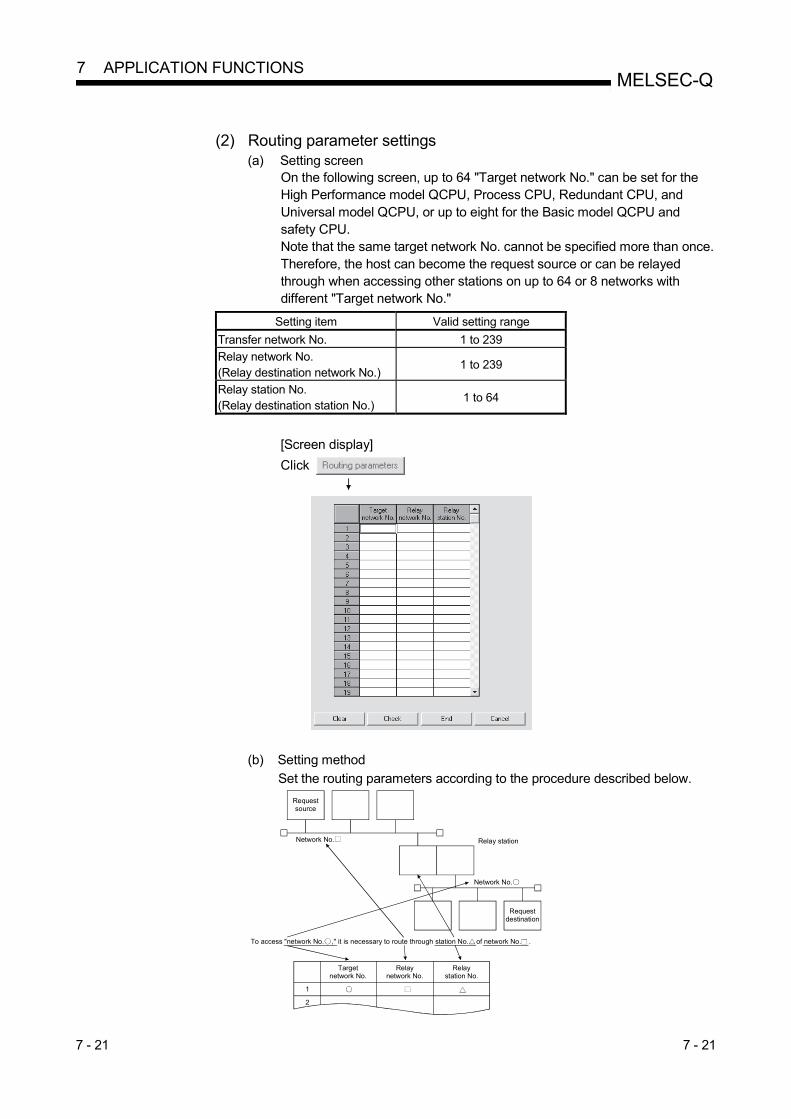
7 - 21 7 - 21
MELSEC-Q 7 APPLICATION FUNCTIONS
(2) Routing parameter settings
(a) Setting screen On the following screen, up to 64 "Target network No." can be set for the High Performance model QCPU, Process CPU, Redundant CPU, and Universal model QCPU, or up to eight for the Basic model QCPU and safety CPU. Note that the same target network No. cannot be specified more than once. Therefore, the host can become the request source or can be relayed through when accessing other stations on up to 64 or 8 networks with different "Target network No."
Setting item Valid setting range
Transfer network No. 1 to 239
Relay network No. (Relay destination network No.)
1 to 239
Relay station No. (Relay destination station No.)
1 to 64
[Screen display] Click
(b) Setting method
Set the routing parameters according to the procedure described below. Requestsource
Network No. Relay station
Network No.
To access "network No. ," it is necessary to route through station No. of network No. .
Requestdestination
1
2
Targetnetwork No.
Relaynetwork No.
Relaystation No.

7 - 22 7 - 22
MELSEC-Q 7 APPLICATION FUNCTIONS
(3) Settings for different network system configurations and setting
contents The stations to set for the transient transmission and the contents of the routing parameters vary depending on the system configuration.
(a) Single network system
It is not necessary to set the routing parameters for the transient transmission to the same network.
Requestsource
Network No. 1
Requestdestination
(b) Multiple network system: two networks
Set the routing parameters only for the request source station. The route for reaching the request destination (network number 2) must be
set for the request source station.
Relay station
Requestsource
Network No. 1
Requestdestination
Network No. 2
(c) Multiple network system: three networks Set the routing parameters for the request source and the relay stations.
The route for reaching the request destination (network number 3) must be
set for the request source. The route for reaching the request destination (network number 3) must be
set for relay station 1).
The route for reaching the request source (network number 1) must be set for relay station 2).
Relay station 1)
Requestsource
Network No. 1
Requestdestination
Network No. 2 Network No. 3
Relay station 2)
(d) Multiple network system: four networks
Set the routing parameters for the request source station and the relay stations.
The route for reaching the request destination (network number 4) must be
set for the request source station. The route for reaching the request destination (network number 4) must be
set for relay station 1) (the relay station that is closest to the request source).
The route for reaching the request source (network number 1) must be set for relay station 2) (the relay station that is closest to the request destination).
The routes for reaching the request destination (network 4) and the request
source (network number 1) must be set for relay station 3) (relay station other than 1) and 2)).

7 - 23 7 - 23
MELSEC-Q 7 APPLICATION FUNCTIONS
POINT
(1) When a network is connected in a loop as shown in the figure below, make
sure to set the routing parameters so that the same relay station is routed for both the "route from request source to request designation" and the "route
back from request destination to request source."
Do not set the destination and returning paths to circle the entire loop. The first relay station in the return path from the request destination is determined
by the relay station in the forward path; thus, data cannot be transferred to a
station beyond that relay station and an error occurs.
Requestsource
1
2 4
32
11
23
3 4
15
42
31
No.1 No.8
No.7
No.6Request
destination
No.5No.4
No.3
No.2
C
B
A
A indicates the path from the request source to the request destination.B and C indicate the path from the request destination to the request source.Avoid path C when setting the return path.
(2) When data is sent to a remote network by transient transmission using the
routing parameters, data is transferred through many networks; thus, the amount of transmission data and the number of transmissions may affect the
entire system.
For example, in network number 2 to 5 in the figure above, the link scan time may become temporarily longer and there may be delays in the transient
transmission of the local station because of the transient transmissions from
other networks. When using the routing parameters, design the transient transmission by
considering the entire system.
(3) When multiple network systems are connected with the routing function, the
request source can send requests to destinations in up to eight network
systems (the maximum number of relay stations is seven stations).

7 - 24 7 - 24
MELSEC-Q 7 APPLICATION FUNCTIONS
(4) Calculation of transmission delay time
The processing time of the transient transmission instruction to access a station
on other network in a multiple network system can be obtained by adding the
following transmission delay factors.
(Routing transmission delay time) = (processing time from request source to relay station)
+ (processing time from relay station to request destination)
(a) Processing time from request source to relay station
This is the transmission delay time from the request source (the station that
executed the instruction) to the relay station that performs the routing. In the following example, it is the time required for the data to be transmitted from
station 1MP1 to station 1NS3.
Use the equation for the transmission delay time described in Section 3.3.2 to calculate the delay time.
(b) Processing time from relay station to request destination
This is the transmission delay time from the relay station to the request
destination (the station accessed with the instruction). In the following example, it is the time required for the data to be transmitted from station
2MP1 to station 2NS3.
Use the equation for the transmission delay time described in Section 3.3.2 to calculate the delay time.
REMARKS
When three or more networks are relayed through by means of routing, add the processing time from one relay station to the other relay station to the routing
transmission delay time.

7 - 25 7 - 25
MELSEC-Q 7 APPLICATION FUNCTIONS
(5) Setting example
The routing parameter setting examples (A, B) are explained using the following
system configuration.
POINT
(1) Since only one network module can be installed with the Basic model QCPU,
Q00UJCPU, Q00UCPU, Q01UCPU and safety CPU, it cannot be used as a relay station.
(2) For access via a redundant system, the routing parameters of the request
source or relay station(s) must be changed with the RTWRITE instruction if system switching occurs in the redundant system.
For details, refer to Section 7.10.8.
(a) Setting example A The routing parameter must be set for request source 10).
8NS3 9NS38NS2 9MP1
10) Request source 11) Relay station 12) Request destination
No. Target
network No.
Relay
network No.
Relay
station No.
10) Request source 1 [9] [8] [2]

7 - 26 7 - 26
MELSEC-Q 7 APPLICATION FUNCTIONS
(b) Setting example B The routing parameters must be set for the request source 1), relay station
2), relay station 3), relay station 4), relay station 5), relay station 6), relay
station 7), and relay station 8). In addition, there are two types of routing parameter settings; one is used
when sending data from the request source to the request destination
(when sending a request), and the other is used when returning from the request destination to the request source (when sending a response).
Either one of them or both must be set for each station.
1NS3 1NS2 2MP1 2NS2 3NS3 3NS2 4MP1
7MP1 6NS2 6MP1 5NS2 5MP1 4NS2
7NS2 8MP1 8NS4
1) Request source 2) Relay station 3) Relay station 4) Relay station
5) Relay station6) Relay station7) Relay station
8) Relay station 9) Request destination
1) Request source No.
Target
network No.
Relay
network No.
Relay
station No.
1 [8] [1] [2] Used when sending a request
2) Relay station 1 [8] [2] [2] Used when sending a request
3) Relay station 1 [8] [3] [2] Used when sending a request
2 [1] [2] [1] Used when sending a response
4) Relay station 1 [8] [4] [2] Used when sending a request
2 [1] [3] [3] Used when sending a response
5) Relay station 1 [8] [5] [2] Used when sending a request
2 [1] [4] [1] Used when sending a response
6) Relay station 1 [8] [6] [2] Used when sending a request
2 [1] [5] [1] Used when sending a response
7) Relay station 1 [8] [7] [2] Used when sending a request
2 [1] [6] [1] Used when sending a response
8) Relay station 1 [1] [7] [1] Used when sending a response
POINT
If a transient transmission (SEND, READ, SREAD, WRITE, SWRITE or REQ) was
terminated abnormally, the "Time" when an error was detected, "Abnormal
detection network number," and "Abnormal detection station number" can be checked from the control data of the instruction used.
For detail on these instructions, refer to Section 7.4.5.

7 - 27 7 - 27
MELSEC-Q 7 APPLICATION FUNCTIONS
7.4.3 Group function
The group function is used to group the target stations of a transient transmission and
send data to all of the stations in a group with a single instruction. One network may have a maximum of 32 groups.
By setting a group specification to the target station number in the control data of a
dedicated link instruction, stations with the matching group number retrieve the transient data.
However, whether or not the transient transmission is normally completed cannot be
verified because the data is transmitted to multiple stations. (1) Visual representation of the function
The following figure shows an example of grouping. When a transient transmission is executed by specifying group number 1, all of the three stations,
1NS3, 1NS5 and 1NS6, retrieve the transient data.
1MP1 1NS2 1NS3
Group No. 1
1NS6 1NS5 1NS4
Group No. 1 Group No. 1 (2) Setting method
Set the group number of the target network module using the following network parameters from GX Developer.
Set the desired group number.
Setting
Item Valid setting range Default
Parameter screen Group No. 1 to 32 0 (no group specification)
Control data target station No. 81H(1) to A0H (32) (3) Transient transmission instructions that allows group specification
No. Instruction Description Reference
1 SEND Data sending Section 7.4.5 (1)
2 (S)WRITE Writes to word device of other station Section 7.4.5 (2)
3 REQ Requests transient transmission to other station Section 7.4.5 (3)
4 ZNWR Writes to word device of other station Section 7.4.5 (4)
5 RRUN Remote RUN Section 7.4.5 (5)
6 RSTOP Remote STOP Section 7.4.5 (5)
7 RTMWR Writes other station clock data Section 7.4.5 (6)
8 Clock setting GX Developer Section 7.4.7
9 Remote RUN/STOP GX Developer GX Developer Operating Manual
POINT The execution of the transient transmission using the group function cannot be verified. When this mode of transient transmission is executed successively, a "No free area in the receive buffer" (error code: F222) may occur. Design the system thoroughly to allow for a sufficient interval between executions, and make sure to test (debug) to confirm that successive executions can be performed without generating any error.

7 - 28 7 - 28
MELSEC-Q 7 APPLICATION FUNCTIONS
7.4.4 Message sending function using the logical channel numbers
The message sending function using the logical channel numbers 1 is useful when there are many kinds of information and the receiving station side needs to selectively receive only some of the send messages. The sending station side is equivalent to a broadcast station that delivers messages to logical channels, and the receiving station side is equivalent to a television receiver in an ordinary household that can switch between logical channels. The sending station side executes the transient transmission by attaching an address for a logical channel without specifying a specific station number (although specification of station numbers is also possible). All the other stations on a single network receive the send data, and then the receiving stations delete the messages except for the messages whose logical channel number matches with the one set by the receiving stations.
1: The logical channel refers to an input channel that can be changed by the sequence program. There are eight physical input channels, but up to 64 channel numbers can be set by modifying the link special register value.
(1) Visual representation of the function When the message is sent from the network module D to logical channel 9, only the network modules A , C where logical channel 9 has been set can receive it. The network module B does not receive it since logical channel 9 has not been set there.
QCPU QJ71BR11
QCPU QJ71BR11
8
3
Channel 12
channel 14
channel 12
channel 10
channel 9
Receive side
Logical
channel 15J.RECV
Receive command
Device memoryQCPU QJ71
BR11
8
3
2
Create data command
Send message
data creation
J.SEND
Send command
Send message data
Device memory
QCPU QJ71BR11
QCPU QJ71BR11
QCPU QJ71
BR11
Power
supply
module
QCPU QJ71
BR11
QCPU QJ71
BR11
B
A
C
D
8
3
Channel 1
2
channel 14
channel 12
channel 10
channel 13
Receive side
Logical
channel 15J.RECV
Device memory
8
3
Channel 1
2
channel 14
channel 12
channel 16
channel 9
Receive side
Logical
channel 15J.RECV
Device memory
Power
supply
modulePower
supply
module
Power
supply
module
Receive command
Receive command
Channel 1
channel 9
channel 10
channel 12
channel 15
Receive side
Logical
channel 1

7 - 29 7 - 29
MELSEC-Q 7 APPLICATION FUNCTIONS
POINT
Whether or not channel No.-specified transient transmission has been executed
cannot be verified. If it is executed consecutively, the no free area in the receive buffer error (error
code: F222) may occur. Properly design the system to leave execution intervals
and perform a test (debugging) so that transmission can be executed consecutively.
(2) Setting method
Set the logical channel numbers in the link special registers (SW0008 to SW000F) with the sequence program.
SW No. Name Valid setting range Default
SW0008 Logical channel setting (channel 1) 1 to 64 0: (Logical channel 1) 1
SW0009 Logical channel setting (channel 2) 1 to 64 0: (Logical channel 2) 1
SW000A Logical channel setting (channel 3) 1 to 64 0: (Logical channel 3) 1
SW000B Logical channel setting (channel 4) 1 to 64 0: (Logical channel 4) 1
SW000C Logical channel setting (channel 5) 1 to 64 0: (Logical channel 5) 1
SW000D Logical channel setting (channel 6) 1 to 64 0: (Logical channel 6) 1
SW000E Logical channel setting (channel 7) 1 to 64 0: (Logical channel 7) 1
SW000F Logical channel setting (channel 8) 1 to 64 0: (Logical channel 8) 1
1: The logical channel number is processed as the actual channel number
when "0" is set.
(3) Transient transmission instruction that allows logical channel
specification
No. Instruction Description Reference
1 SEND Sends data Section 7.4.5 (1) (d)

7 - 30 7 - 30
MELSEC-Q 7 APPLICATION FUNCTIONS
7.4.5 Programming
This section describes the formats of dedicated instructions available for network
modules and program examples.
POINT
The descriptions in this section are based on the MELSECNET/H specifications.
For access to CC-Link IE Controller Network or CC-Link IE Field Network, refer to
the manual for the network module used.
1) Instruction execution in transient transmission
To perform the following processing in transient transmission, provide
interlocks:
Using the same channel with multiple instructions
(Refer to Example 1.)
Executing instructions from a redundant system
(Refer to Example 2.)

7 - 31 7 - 31
MELSEC-Q 7 APPLICATION FUNCTIONS
(Example 1) When using the same channel with multiple instructions
One network module has 8 channels for executing instructions. Although these channels can be used at the same time, the same channel cannot be concurrently used for multiple instructions. If execution of multiple instructions are attempted at the same time on the same channel, those to be executed later have to wait. For this reason, create a program as shown below so that flags turn on until the previous instruction is completed.
(To next page)

7 - 32 7 - 32
MELSEC-Q 7 APPLICATION FUNCTIONS

7 - 33 7 - 33
MELSEC-Q 7 APPLICATION FUNCTIONS
POINT
(1) When simultaneously accessing multiple other stations from the host station,
change the channel setting of the host station for each request target.
Station No.3(Host station)
Channel 1Channel 1: Write to station No.1
Channel 2: Read from station No.1
Channel 3: Write to station No.2
Channel 4: Read from station No.2
WRITE
READ
READ
WRITE
Channel 2
Channel 3
Channel 4
Station No.1(Other station)
Station No.2(Other station)
(2) When accessing other stations with the same channel No. specified, make the
next other station access after completion of the preceding access.
The completion status can be confirmed with the completion device of the link
dedicated instruction.
When the next access is attempted before completion of the preceding access
to another station, the link dedicated instruction issued later is not executed.
(3) When making access mutually between the host station and another station,
change the channel of the host station for each link dedicated instruction.
Station No.1(Host station)
Channel 1SEND
RECV
RECV
SEND
Channel 1: For send
Channel 3: For receive
Channel 1: For receive
Channel 3: For sendChannel 3
Channel 1
Channel 3
Station No.2(Other station)
(4) Up to eight instructions are executable at the same time if no duplication is
found in the channel Nos. (1 to 8) specified in the control data of the
instructions.
REMARKS
Do not use the same channel for link dedicated instructions of both the scan
execution program and the interrupt program.
If a channel is being used for a link dedicated instruction of the scan execution
program, the channel is not available for another link dedicated instruction of the
interrupt program.
The instruction of the interrupt program is put in the wait status at this time, and will
be executed at the next scan timing in this case.
If the link dedicated instruction of the interrupt program precedes that of the scan
execution program, however, the latter cannot be executed because the next scan
timing does not exist in the interrupt program.

7 - 34 7 - 34
MELSEC-Q 7 APPLICATION FUNCTIONS
(Example 2) When executing instructions from a redundant system
If system is switched in a redundant system during execution of an
instruction, the instruction will be discontinued in the redundant CPU of
the new control system and will not be completed.
Using the SM1518 (one scan ON after system switching) and the
complete signal, create a program that any instruction being executed will
be continued by the new control system even when the system is
switched in the redundant system.
Arrival confirmed/clock data setting
Channel used by host station
Target station CPU type
Target station network number
Target station number
Number of resend times
Arrival monitoring time
Written data length
Written data
Processing program at normal completion
Processing program at abnormal completion

7 - 35 7 - 35
MELSEC-Q 7 APPLICATION FUNCTIONS
2) Available devices
The following devices are available for the dedicated instructions:
Internal devices File register Constant 2
Bit1 Word
X, Y, M, L, F, V, B T, ST, C, D, W R, ZR K, H, $
1: Word device bit specification is available for bit data.
A bit of a word device is specified with Word device and Bit No. .
(Bit No. must be specified in hexadecimal.)
For example, bit 10 of D0 is specified as D0.A .
Note that bit specification is not allowed for timers (T), retentive timers (ST), and
counters (C).
2: Available devices are given in each of the Constant column.
3) When specifying the target of dedicated instructions by network No.
If multiple network modules with the same network number are
mounted, execution target will be as follows.
CPU type Description
Host station is the
Universal model QCPU
A network module mounted on the slot with the
smallest number in a base unit is targeted.
Host station is not the
Universal model QCPU
A network module to which the smallest start I/O
number has been assigned in the I/O assignment tab of
the PLC parameter dialog box.
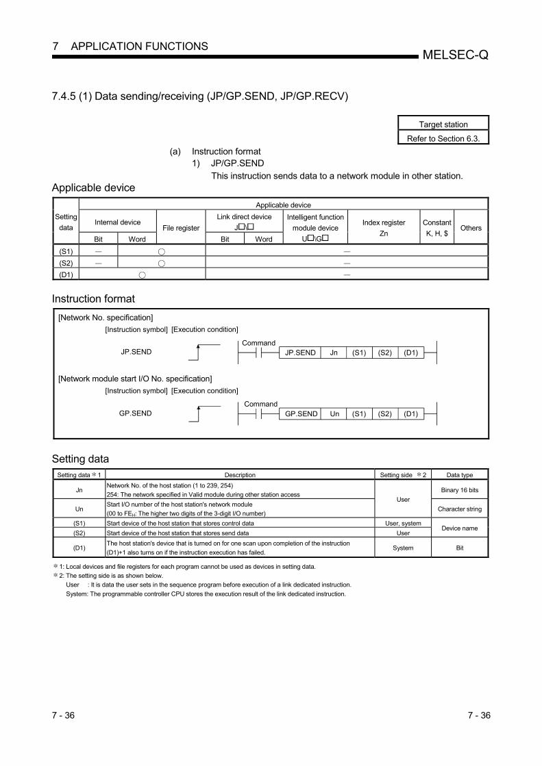
7 - 36 7 - 36
MELSEC-Q 7 APPLICATION FUNCTIONS
7.4.5 (1) Data sending/receiving (JP/GP.SEND, JP/GP.RECV)
Target station
Refer to Section 6.3.
(a) Instruction format 1) JP/GP.SEND
This instruction sends data to a network module in other station. Applicable device
Setting
data
Applicable device
Internal device File register
Link direct device
J \
Intelligent function
module device
U \G
Index register
Zn
Constant
K, H, $ Others
Bit Word Bit Word
(S1) (S2) (D1)
Instruction format
[Network No. specification]
JP.SEND JnCommand
(S1) (S2) (D1)
[Execution condition][Instruction symbol]
JP.SEND
[Network module start I/O No. specification]
GP.SEND UnCommand
(S1) (S2) (D1)
[Execution condition][Instruction symbol]
GP.SEND
Setting data
Setting data 1 Description Setting side 2 Data type
Jn Network No. of the host station (1 to 239, 254)
254: The network specified in Valid module during other station access User
Binary 16 bits
Un Start I/O number of the host station's network module
(00 to FEH: The higher two digits of the 3-digit I/O number) Character string
(S1) Start device of the host station that stores control data User, system Device name
(S2) Start device of the host station that stores send data User
(D1) The host station's device that is turned on for one scan upon completion of the instruction
(D1)+1 also turns on if the instruction execution has failed. System Bit
1: Local devices and file registers for each program cannot be used as devices in setting data.
2: The setting side is as shown below.
User : It is data the user sets in the sequence program before execution of a link dedicated instruction.
System: The programmable controller CPU stores the execution result of the link dedicated instruction.

7 - 37 7 - 37
MELSEC-Q 7 APPLICATION FUNCTIONS
Control data
Device Item Setting data Setting range Setting
side 2
(S1)+ 0 Execution/Error
completion type
b15 b7 b0toto
2)0 0 1) 1) Execution type (bit 0)
0: No arrival confirmation
• When the target station is on the same network
Completed when data are sent from the host station.
Execution source
Target station
Complete • When the target station is on another network
Completed when data reach a relay station on the same network.
Relay station
Execution source
Target station
Complete
1: With arrival confirmation
Completed when data are stored in the specified channel area of the target station.
Relay station
Execution source
Target station
Complete
Complete
Target station
When "0: No arrival confirmation" is specified, even if transmission to the target station is
terminated abnormally in the following cases, it is normal completion on the host station.
• Communication itself was completed normally, although the data sent were erroneous.
• Data could not be stored in the target station because instructions from multiple stations
were sent to the same station. (An error code (F222H) is detected on the target station.) 2) Error completion type (bit 7)
Specify the clock data setup status for error completion.
0: Clock data at the time of error completion is not set in the area starting from (S1)+11.
1: Clock data at the time of error completion is set in the area starting from (S1)+11.
0000H
0001H
0080H
0081H
User
(S1)+1 Completion status
The instruction completion status is stored.
System 0 : Normal
Other than 0 : Error (Refer to Section 8.3 for error codes)
(S1)+2 Channel used by
host station
Specify the channel used by the host station.
1 to 8: Channel 1 to 8 User
(S1)+3
Target station
storage channel
(Logical channel
No.)
Specifies the target station's channel to store the data.
1 to 64: Logical channel 1 to 64 User
(S1)+4 Target station
network No.
Specify the network No. of the target station. 1 to 239
254 User 1 to 239 : Network No.
254 : Specify this when 254 has been set in Jn.
(Continued to the next page)
2: The setting side is as shown below.
User : It is data the user sets in the sequence program before execution of a link dedicated instruction.
System: The programmable controller CPU stores the execution result of the link dedicated instruction.

7 - 38 7 - 38
MELSEC-Q 7 APPLICATION FUNCTIONS
Device Item Setting data Setting range Setting
side 2
(S1)+ 5 Target station No.
Specify the station No. of the target station.
1) Station No. specification
1 to 64
81H to A0H
FFH
User
1 to 64 : Station No.
(To increase the reliability of data, it is recommended to execute the
instruction with the execution type in (S1)+0 set to "1: With arrival
confirmation".)
2) Group specification
81H to A0H : All stations in group No.1 to 32
(Setting is available when the execution type is set to "0: With arrival
confirmation" in (S1)+0.)
3) All stations specification
FFH : All stations of the target network No. (Except the host station)
(Setting is available when the execution type is set to "0: No arrival
confirmation" in (S1)+0.)
When a group is specified, set the group No. of the target station with the network parameters from GX Developer.
(S1)+ 6 (Use prohibited)
(S1)+7 Number of resends
1) For instruction execution
Specify the number of times the instruction is to be resent when it is not completed within
the monitoring time specified in (S1)+8.
(Setting is valid when the execution type is set to "1: With arrival confirmation" in (S1)+0.)
0 to 15 User
2) At instruction completion
The number of resends executed (result) is stored.
(Setting is valid when the execution type is set to "1: With arrival confirmation" in (S1)+0.) System
(S1)+8 Arrival monitoring
time
Specify the monitoring time required for instruction completion.
(Setting is available when the execution type is set to "1: With arrival confirmation" in
(S1)+0.)
If an instruction is not completed within this time, it will be resent the number of times
specified in (S1)+7. 0 to 32767 User
0 : 10 seconds
1 to 32767 : 1 to 32767 seconds
(S1)+9 Send data length Specify the send data size of (S2) to (S2)+n. (Refer to Section 2.2.1.)
1 to 960: Number of send data (words) 1 to 960 User
(S1)+10 (Use prohibited)
(S1)+11 Clock set flag
The valid or invalid status of the data in the area starting from (S1)+12 is stored.
(Data are stored when "1: Clock data at the time of error completion is set in the area
starting from (S1)+11." is set in the error completion type in (S1)+0).
Note that the stored value will not be cleared even after the dedicated instruction is
completed.
0: Invalid
1: Valid
System
(Continued to the next page)
2: The setting side is as shown below.
Use : It is data the user sets in the sequence program before execution of a link dedicated instruction.
System: The programmable controller CPU stores the execution result of the link dedicated instruction.
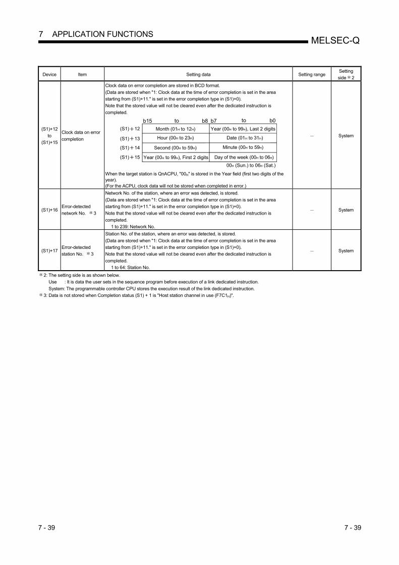
7 - 39 7 - 39
MELSEC-Q 7 APPLICATION FUNCTIONS
Device Item Setting data Setting range Setting
side 2
(S1)+12
to
(S1)+15
Clock data on error
completion
Clock data on error completion are stored in BCD format.
(Data are stored when "1: Clock data at the time of error completion is set in the area
starting from (S1)+11." is set in the error completion type in (S1)+0).
Note that the stored value will not be cleared even after the dedicated instruction is
completed.
(S1) 12
(S1) 13
(S1) 14
(S1) 15
Hour (00H to 23H) Date (01H to 31H)
b15 b7 b0toto b8
Second (00H to 59H) Minute (00H to 59H)
Year (00H to 99H), First 2 digits Day of the week (00H to 06H)
00H (Sun.) to 06H (Sat.)
Month (01H to 12H) Year (00H to 99H), Last 2 digits
When the target station is QnACPU, "00H" is stored in the Year field (first two digits of the year). (For the ACPU, clock data will not be stored when completed in error.)
System
(S1)+16 Error-detected
network No. 3
Network No. of the station, where an error was detected, is stored.
(Data are stored when "1: Clock data at the time of error completion is set in the area
starting from (S1)+11." is set in the error completion type in (S1)+0).
Note that the stored value will not be cleared even after the dedicated instruction is
completed.
1 to 239: Network No.
System
(S1)+17 Error-detected
station No. 3
Station No. of the station, where an error was detected, is stored.
(Data are stored when "1: Clock data at the time of error completion is set in the area
starting from (S1)+11." is set in the error completion type in (S1)+0).
Note that the stored value will not be cleared even after the dedicated instruction is
completed.
1 to 64: Station No.
System
2: The setting side is as shown below.
Use : It is data the user sets in the sequence program before execution of a link dedicated instruction.
System: The programmable controller CPU stores the execution result of the link dedicated instruction.
3: Data is not stored when Completion status (S1) + 1 is "Host station channel in use (F7C1H)".

7 - 40 7 - 40
MELSEC-Q 7 APPLICATION FUNCTIONS
POINT
(1) When sending data to the same channel of the receiving station, execute the
sending after the receiving station reads data using the RECV instruction.
If the sending station sends data to the same channel of the receiving station
before the receiving station reads data using the RECV instruction, an error
will occur.
CPU (Sending station) Network module
RECV
SEND
SEND
Channel 3
Error
Logical channel(channel 5)
Network moduleCPU
(Receiving station)
to
(2) As the target station of data sending, specify the network number and station
number of the network module or Ethernet module that will receive a request
from the sending station.
: In the following figure, specify the network number and station number of
the first network module.
You cannot execute the SEND instruction after specifying any module
other than the network module or Ethernet module that will receive a
request from the sending station.
: In the following figure, you cannot execute the SEND instruction after
specifying the network number and station number of the second network
module.
Networkmodule
Networkmodule
Networkmodule
(Sending station)
SEND
CPU CPU
Network No.1 Network No.2
(Second module)(First module)(Target station)
(3) Number of resends ((S1)+7) requires to be set every time an instruction is
executed.

7 - 41 7 - 41
MELSEC-Q 7 APPLICATION FUNCTIONS
2) JP/GP.RECV
This instruction is used when sending data from the network module in
another station. Applicable device
Setting
data
Applicable device
Internal device File register
Link direct device
J \
Intelligent function
module device
U \G
Index register
Zn
Constant
K, H, $ Others
Bit Word Bit Word
(S1) (D1) (D2)
Instruction format
[Network No. specification]
JP.RECV JnCommand
(S1) (D1) (D2)
[Execution condition][Instruction symbol]
JP.RECV
[Network module start I/O No. specification]
GP.RECV UnCommand
(S1) (D1) (D2)
[Execution condition][Instruction symbol]
GP.RECV
Setting data
Setting data 1 Description Setting side 2 Data type
Jn Network No. of the host station (1 to 239, 254)
254: The network specified in Valid module during other station access User
Binary 16 bits
Un Start I/O number of the host station's network module
(00 to FEH: The higher two digits of the 3-digit I/O number) character string
(S1) Start device of the host station that stores control data User, system
Device name (D1)
Start device of the host station that stores receive data
(A contiguous area for the receive data length is required.)
System
(D2)
The host station's device that is turned on for one scan upon completion of the
instruction
(D2)+1 also turns on if the instruction execution has failed.
Bit
1: Local devices and file registers for each program cannot be used as devices in setting data.
2: The setting side is as shown below.
User : It is data the user sets in the sequence program before execution of a link dedicated instruction.
System: The programmable controller CPU stores the execution result of the link dedicated instruction.

7 - 42 7 - 42
MELSEC-Q 7 APPLICATION FUNCTIONS
Control data
Device Item Setting data Setting range Setting
side 2
(S1)+0 Error completion
type
b15 b7 b0toto
1)b8 b6
0 to 0 0 to 0 1) Error completion type (bit 7)
Specify the clock data setup status for error completion.
0: Clock data at the time of error completion is not set in the area starting from (S1)+11.
1: Clock data at the time of error completion is set in the area starting from (S1)+11.
0000H
0080H User
(S1)+1 Completion status
The instruction completion status is stored.
System 0 : Normal
Other than 0 : Error (Refer to Section 8.3 for error codes)
(S1)+2 Host station channel Specify the channel of the host station, where receive data are stored.
1 to 8: Channel 1 to 8 User
(S1)+3 Channel used by
sending station
Stores the channel used by the sending station.
1 to 8: Channel System
(S1)+4 Network No. of
sending station
Stores network No. of the sending station.
1 to 239: Network No. System
(S1)+5 Sending station No. Stores station No. of the sending station.
System 1 to 64: Station No.
(S1)+6 (Use prohibited) (S1)+7 (Use prohibited)
(S1)+8 Arrival monitoring
time
Specify the monitoring time required for instruction completion.
If not completed within the time, the instruction is terminated with an error. 0 to 32767 User
0 : 10 seconds
1 to 32767 : 1 to 32767 seconds
(S1)+9 Receive data length Stores the receive data size stored in (D1) to (D1)+ n.
1 to 960: Number of received data (words) System
(S1)+10 (Use prohibited)
(S1)+11 Clock set flag
The valid or invalid status of the data in the area starting from (S1)+12 is stored.
(Data are stored when "1: Clock data at the time of error completion is set in the area starting
from (S1)+11." is set in the error completion type in (S1)+0).
Note that the stored value will not be cleared even after the dedicated instruction is
completed.
0: Invalid
1: Valid
System
(S1)+12
to
(S1)+15
Clock data on error
completion
Clock data on error completion are stored in BCD format.
(Data are stored when "1: Clock data at the time of error completion is set in the area starting
from (S1)+11." is set in the error completion type in (S1)+0).
Note that the stored value will not be cleared even after the dedicated instruction is
completed.
(S1) 12
(S1) 13
(S1) 14
(S1) 15
Hour (00H to 23H) Date (01H to 31H)
b15 b7 b0toto b8
Second (00H to 59H) Minute (00H to 59H)
Year (00H to 99H), First 2 digits Day of the week (00H to 06H)
00H (Sun.) to 06H (Sat.)
Month (01H to 12H) Year (00H to 99H), Last 2 digits
System
(Continued to the next page)
2: The setting side is as shown below.
User : It is data the user sets in the sequence program before execution of a link dedicated instruction.
System: The programmable controller CPU stores the execution result of the link dedicated instruction.

7 - 43 7 - 43
MELSEC-Q 7 APPLICATION FUNCTIONS
Device Item Setting data Setting range Setting
side 2
(S1)+16 Error-detected
network No. 3
Network No. of the station, where an error was detected, is stored.
(Data are stored when "1: Clock data at the time of error completion is set in the area starting
from (S1)+11." is set in the error completion type in (S1)+0).
Note that the stored value will not be cleared even after the dedicated instruction is
completed.
1 to 239: Network No.
System
(S1)+17 Error-detected
station No. 3
Station No. of the station, where an error was detected, is stored.
(Data are stored when "1: Clock data at the time of error completion is set in the area starting
from (S1)+11." is set in the error completion type in (S1)+0).
Note that the stored value will not be cleared even after the dedicated instruction is
completed.
1 to 64: Station No.
System
2: The setting side is as shown below.
User : It is data the user sets in the sequence program before execution of a link dedicated instruction.
System: The programmable controller CPU stores the execution result of the link dedicated instruction.
3: Data is not stored when Completion status (S1) + 1 is "Host station channel in use (F7C1H)".
POINT
When the network modules on the same network are installed at the receive
station, execute RECV instruction by specifying Un of the network module which
stores the data sent by SEND instruction.
Specifying Jn does not execute RECV instruction.
(Example) Specify "U2" when executing the RECV instruction at station No. 3 in
response to the SEND instruction from station No. 1.
(Send station)
SEND
QCPU QJ71BR11
QCPU
Network No. 1
(Receive station)
RECV U2Station No. 1
QJ71BR11
QJ71BR11
Station No. 2
Station No. 3

7 - 44 7 - 44
MELSEC-Q 7 APPLICATION FUNCTIONS
(b) Instruction execution timing 1) Normal completion
0 END 0 END 0 END 0 END 0 END
SEND
0 END END 0 END 0 END
RECV
0 END 0
Network module
Network module Logical channel 3 (channel 3)
Channel 1
Data sending
Storage complete
Sequence scan
Send command
(When with arrival confirmation)
One scan
Sequence scan
One scan
Receive data
Sending station CPU
Receiving station CPU
Send completion device(Device designated in (D1))
Send completion device(Device at (D1)+1) OFF
OFF
OFF OFF
OFF
OFF OFF
OFF
ON
OFFON
ONOFF
ON
RECV instructionexecution request flagSB00A2 (For channel 3)
Receive completion device(Device designated in (D2))
Receive completion device(Device at (D2)+1)
Receive data storage device(Device designated in (D1))

7 - 45 7 - 45
MELSEC-Q 7 APPLICATION FUNCTIONS
2) Abnormal completion
[In case of the SEND instruction]
Send command
0 ENDSequence scan 0 END 0 END 0 END 0 END
SEND
One scan
Error code
Network module Channel 1
Send errorResend (in case of 2 times)
Sending station CPU
Datasending
Datasending
Datasending
Completion status(Device at (S1)+1)
Send completion device(Device at (D1)+1)
Send completion device(Device designated in (D1))
OFF
OFF
OFF OFFON
OFFON
OFFON
[In case of the RECV instruction]
OFF
OFF
OFFON
OFFON
OFFON
0 ENDSequence scan END 0 END 0 END
RECV
0 END 0
Receiving station CPU
One scan
? Error code
Network module Logical channel 3 (channel 3)
Arrival monitoring time over
RECV instructionexecution request flagSB00A2 (For channel 3)
Receive completion device(Device designated in (D2))
Receive completion device(Device at (D2)+1)
Completion status(Device at (S1)+1)

7 - 46 7 - 46
MELSEC-Q 7 APPLICATION FUNCTIONS
(c) Program example 1 (target station is specified)
Station number 3 uses channel 3 and sends data to the target station of
station number 15's storage channel 5 (logical channel 5) using the SEND
instruction.
Upon receiving the data, station number 15 reads data from channel 5.
CPU
Network module
(station No. 3) CPU
SEND
Network module
(station No. 15)
RECV
Network No. 7
Logical channel 1 (channel 1)Channel 1
Channel 2
Channel 3
Channel 4
Channel 5
Channel 6
Channel 7
Channel 8
Logical channel 2 (channel 2)
Logical channel 3 (channel 3)
Logical channel 4 (channel 4)
Logical channel 5 (channel 5)
Logical channel 6 (channel 6)
Logical channel 7 (channel 7)
Logical channel 8 (channel 8)
1) Program for station number 3 (SEND instruction)
When actually using the following program, interlock the program by
referring to Section 6.1.

7 - 47 7 - 47
MELSEC-Q 7 APPLICATION FUNCTIONS
2) Program for station number 15 (RECV instruction)
When actually using the following program, provide interlocks in the
program referring to Section 6.1.

7 - 48 7 - 48
MELSEC-Q 7 APPLICATION FUNCTIONS
(d) Program example 2 (logical channel numbers are used)
Station number 1 uses channel 2 and sends message data to the target
station storage channel number 13 (logical channel 13) using the SEND
instruction.
Station number 2 executes the RECV instruction and reads the received
data from channel 5 (logical channel 13). At the same time, station number
4 executes the RECV instruction and reads the received data from channel
6 (logical channel 13).
Station number 3 uses channel 2 and sends the message data to the target
station storage channel 18 (logical channel 18) using the SEND instruction,
but it is not received because there is no matching logical channel number.
CPU
Network moduleStation No. 1
SEND
CPU
Network moduleStation No. 3
SEND
CPUNetwork module
Station No. 2
RECV
CPU
RECV
Network moduleStation No. 4
Network No. 7
Channel 1 (logical channel 1)
Channel 2 (logical channel 2)
Channel 3 (logical channel 3)
Channel 4 (logical channel 4)
Channel 5 (logical channel 5)
Channel 6 (logical channel 6)
Channel 7 (logical channel 7)
Channel 8 (logical channel 8)
Control data target station logical channel 13
Control data target station logical channel 18
Channel 1 (logical channel 1)
Channel 2 (logical channel 2)
Channel 3 (logical channel 3)
Channel 4 (logical channel 4)
Channel 5 (logical channel 13)
Channel 6 (logical channel 23)
Channel 7 (logical channel 33)
Channel 8 (logical channel 8)
Channel 1 (logical channel 1)
Channel 2 (logical channel 2)
Channel 3 (logical channel 3)
Channel 4 (logical channel 4)
Channel 5 (logical channel 12)
Channel 6 (logical channel 13)
Channel 7 (logical channel 7)
Channel 8 (logical channel 8)
Channel 1 (logical channel 1)
Channel 2 (logical channel 2)
Channel 3 (logical channel 3)
Channel 4 (logical channel 4)
Channel 5 (logical channel 5)
Channel 6 (logical channel 6)
Channel 7 (logical channel 7)
Channel 8 (logical channel 8)

7 - 49 7 - 49
MELSEC-Q 7 APPLICATION FUNCTIONS
1) Program for station number 1 (SEND instruction)
When using the following program, provide interlocks in the program
referring to Section 6.1.

7 - 50 7 - 50
MELSEC-Q 7 APPLICATION FUNCTIONS
2) Program for receiving station (station number 2) (RECV instruction)
When using the following program, provide interlocks in the program
referring to Section 6.1.

7 - 51 7 - 51
MELSEC-Q 7 APPLICATION FUNCTIONS
(e) Program example 3 (when specifying a target station to execute an
instruction to the redundant system)
When the target station is in a redundant system, the SEND instruction
must be executed after judging whether it is a control system.
If the target station is on the standby system, the RECV instruction is not
executed and the target station saving channel is not available.
The program example shown below is an interlock example for sending
data from station number 3 of network number 7 to the control system of
the redundant system made up of station numbers 1 and 2 of the same
network.
Processing program at send completion
Processing program at normal completion
Processing program at abnormal completion
With arrival confirmation/set clock data
Channel used by host station
Target station number (when station No. 1 is a control system)
Target station number (when station No. 2 is a control system)
Target station saving channel (logical channel number)
Target station network number
Number of resend times
Arrival monitoring time (20s)
Sent data length (four words)
Sent data
Reading error codes, etc.
Control data setting instruction
Sent data setting instruction
Sending instruction
When designating a target station number, provide an interlock between SW01FC to SW01FF (redundant system status) for judging whether the target station is a control system.

7 - 52 7 - 52
MELSEC-Q 7 APPLICATION FUNCTIONS
POINT
When the SEND instruction is executed to the redundant system, the processing of
the RECV instruction and interrupt program (RECVS instruction) depends on the
following conditions: (1) When the SEND instruction is executed to the control system and the system
is switched before execution of the RECV instruction and the interrupt program
If the control system is switched to the standby system before execution of
the RECV instruction and the interrupt program, the control system retains the
instruction execution request flags (SB00A0 to SB00A7) for the RECV
instruction and the interrupt factor (interrupt pointer) of the interrupt program.
If the standby system is returned to the control system due to system
switching, the RECV instruction and the interrupt program will be executed
according to the retained instruction execution request flags and interrupt
factor. (2) When the SEND instruction is executed to the standby system
When standby system receives data from the sending station, it retains the
instruction execution request flags (SB00A0 to SB00A7) for the RECV
instruction and the interrupt factor (interrupt pointer) of the interrupt program.
If the standby system is switched to the control system, the RECV instruction
and the interrupt program will be executed according to the retained
instruction execution request flags and interrupt factor.

7 - 53 7 - 53
MELSEC-Q 7 APPLICATION FUNCTIONS
7.4.5 (2) Reading from/writing to word devices of other stations (JP/GP.READ,
JP/GP.SREAD, JP/GP.WRITE, JP/GP.SWRITE)
Target station
Refer to Section 6.3.
(a) Instruction format
1) JP/GP.READ and JP/GP.SREAD
These instructions are used to read data from devices of a
programmable controller on another station. (In units of words)
With the SREAD instruction, a device on another station turns on when
data reading is completed. (The other station can recognize that data
have been read out with the SREAD instruction.) Applicable device
Setting
data
Applicable device
Internal device File register
Link direct device
J \
Intelligent function
module device
U \G
Index register
Zn
Constant
K, H, $ Others
Bit Word Bit Word
(S1)
(S2) 1
(D1) (D2) (D3)
1: Any of T, C, D, W, ST, SD, and SW can be used.
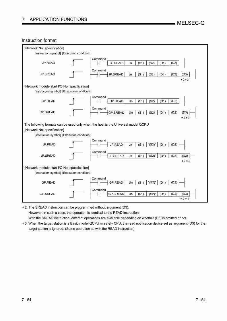
7 - 54 7 - 54
MELSEC-Q 7 APPLICATION FUNCTIONS
Instruction format
[Network No. specification]
JP.READ JnCommand
(S1) (S2) (D1)
[Execution condition]
(D2)
[Instruction symbol]
JP.READ
JP.SREAD JnCommand
(S1) (S2) (D1) (D2)
2 3
(D3)JP.SREAD
[Network module start I/O No. specification]
GP.READ UnCommand
(S1) (S2) (D1)
[Execution condition]
(D2)
[Instruction symbol]
GP.READ
GP.SREAD UnCommand
(S1) (S2) (D1) (D2)
2 3
(D3)GP.SREAD
The following formats can be used only when the host is the Universal model QCPU
[Network No. specification]
JP.READ JnCommand
(S1) (D1)
[Execution condition]
(D2)"(S2)"
[Instruction symbol]
JP.READ
JP.SREAD JnCommand
(S1) (D1) (D2) (D3)"(S2)"JP.SREAD
2 3 [Network module start I/O No. specification]
GP.READ UnCommand
(S1) (D1)
[Execution condition]
(D2)"(S2)"
[Instruction symbol]
GP.READ
GP.SREAD UnCommand
(S1) (D1) (D2) (D3)GP.SREAD "(S2)"
2 3 2: The SREAD instruction can be programmed without argument (D3).
However, in such a case, the operation is identical to the READ instruction.
With the SREAD instruction, different operations are available depending on whether (D3) is omitted or not.
3: When the target station is a Basic model QCPU or safety CPU, the read notification device set as argument (D3) for the
target station is ignored. (Same operation as with the READ instruction)

7 - 55 7 - 55
MELSEC-Q 7 APPLICATION FUNCTIONS
Setting data
Setting data 4 Description Setting side 5 Data type
Jn Network No. of the host station (1 to 239, 254)
254: The network specified in Valid module during other station access User Binary 16 bits
Un Start I/O number of the host station's network module
(00 to FEH: The higher two digits of the 3-digit I/O number)
(S1) Start device of the host station that stores control data User, system
Device name (S2) Target station's start device where data to be read are stored User
(D1) The host station's start device where readout data will be stored
(A contiguous area for the read data length is required.)
System (D2) The host station's device that is turned on for one scan upon completion of the instruction
(D2)+1 also turns on if the instruction execution has failed. Bit
(D3) The target station's device that is turned on for one scan upon completion of the instruction.
(The target station can recognize that data have been read out to the other station.)
4: Local devices and file registers for each program cannot be used as devices in setting data.
5: The setting side is as shown below.
User : It is data the user sets in the sequence program before execution of a link dedicated instruction.
System: The programmable controller CPU stores the execution result of the link dedicated instruction.

7 - 56 7 - 56
MELSEC-Q 7 APPLICATION FUNCTIONS
Control data
Device Item Setting data Setting range Setting
side 5
(S1)+0 Error completion
type
b15 b7 b0toto
0 1) 0 1 1) Error completion type (bit 7)
Specify the clock data setup status for error completion.
0: Clock data at the time of error completion is not set in the area starting from (S1)+11.
1: Clock data at the time of error completion is set in the area starting from (S1)+11.
0001H
0081H User
(S1)+1 Completion status
The instruction completion status is stored.
System 0 : Normal
Other than 0 : Error (Refer to Section 8.3 for error codes)
(S1)+2 Channel used by
host station
Specify the channel used by the host station.
1 to 8: Channel 1 to 8 User
(S1)+3 Target station's
CPU type
Specify the CPU module on the station to be accessed.
0000H
03D0H to 03D3H
03E0H to 03E3H
03FFH
User
Setting value Description
0000H
Target station CPU/control CPU/own system CPU
Control CPU (The access target is the same as when "03FFH" is
specified.)
03D0H 6 Control system CPU
03D1H 6 Standby system CPU
03D2H 6 System A CPU
03D3H 6 System B CPU
03E0H 7 Control CPU (single CPU system)
Multiple CPU system No.1
03E1H 7 Multiple CPU system No.2
03E2H 7 Multiple CPU system No.3
03E3H 7 Multiple CPU system No.4
03FFH 6 Control CPU When the instruction is executed with control system CPU (03D0H) or standby system CPU
(03D1H) specified, if system switching occurs at the target station, the instruction execution
may fail. (Error code: 4244H, 4248H)
If the instruction has failed with the above error, execute it again.
(S1)+4 Target station
network No.
Specify the network No. of the target station. 1 to 239
254 User 1 to 239 : Network No.
254 : Specify this when 254 has been set in Jn.
(S1)+5 Target station No. Specify the station No. of the target station.
1 to 64: Station No. 1 to 64 User
(S1)+6 (Use prohibited)
(S1)+7 Number of resends
1) For instruction execution
Specify the number of times the instruction is to be resent when it is not completed within
the monitoring time specified in (S1)+8.
0 to 15 User
2) At instruction completion
The number of resends executed (result) is stored. System
(Continued to the next page)
5: The setting side is as shown below.
User : It is data the user sets in the sequence program before execution of a link dedicated instruction.
System: The programmable controller CPU stores the execution result of the link dedicated instruction.
6: The CPU type can be specified when the host station is a network module of which function version is either D or later or the following.
• Network module: Serial number (first five digits) "10101" or later
(The CPU module cannot be specified in the case other than the above. Only access to the control CPU is available.)
7: The CPU type can be specified when the QCPUs and network modules of the host station or target station are the following versions.
• Network module: Serial number (first five digits) "06092" or later
• QCPU: Serial number (first five digits) "06092" or later
(The CPU module cannot be specified in the case other than the above. Only access to the control CPU is available.)

7 - 57 7 - 57
MELSEC-Q 7 APPLICATION FUNCTIONS
Device Item Setting data Setting range Setting
side 5
(S1)+8 Arrival monitoring time
Specify the monitoring time required for instruction completion.
If an instruction is not completed within this time, it will be resent the number of times
specified in (S1)+7. 0 to 32767 User
0 : 10 seconds
1 to 32767 : 1 to 32767 seconds
(S1)+9 Read data length Specify the size of the read data. (Refer to Section 2.2.1)
1 to 960: Number of read data (words) 1 to 960 User
(S1)+10 (Use prohibited)
(S1)+11 Clock set flag
The valid or invalid status of the data in the area starting from (S1)+12 is stored.
(Data are stored when "1: Clock data at the time of error completion is set in the area
starting from (S1)+11." is set in the error completion type in (S1)+0).
Note that the stored value will not be cleared even after the dedicated instruction is
completed.
0: Invalid
1: Valid
System
(S1)+12
to
(S1)+15
Clock data on error
completion
Clock data on error completion are stored in BCD format.
(Data are stored when "1: Clock data at the time of error completion is set in the area
starting from (S1)+11." is set in the error completion type in (S1)+0).
Note that the stored value will not be cleared even after the dedicated instruction is
completed.
(S1) 12
(S1) 13
(S1) 14
(S1) 15
Hour (00H to 23H) Date (01H to 31H)
b15 b7 b0toto b8
Second (00H to 59H) Minute (00H to 59H)
Year (00H to 99H), First 2 digits Day of the week (00H to 06H)
00H (Sun.) to 06H (Sat.)
Month (01H to 12H) Year (00H to 99H), Last 2 digits
When the target station is QnACPU, "00H" is stored in the Year field (first two digits of the
year).
(Clock data will not be stored when errors have been completed in the case of the
ACPU.)
System
(S1)+16 Error-detected network
No. 8
Network No. of the station, where an error was detected, is stored.
(Data are stored when "1: Clock data at the time of error completion is set in the area
starting from (S1)+11." is set in the error completion type in (S1)+0).
Note that the stored value will not be cleared even after the dedicated instruction is
completed.
1 to 239: Network No.
System
(S1)+17 Error-detected station No.
8
Station No. of the station, where an error was detected, is stored.
(Data are stored when "1: Clock data at the time of error completion is set in the area
starting from (S1)+11." is set in the error completion type in (S1)+0).
Note that the stored value will not be cleared even after the dedicated instruction is
completed.
1 to 64: Station No.
System
5: The setting side is as shown below.
User : It is data the user sets in the sequence program before execution of a link dedicated instruction.
System: The programmable controller CPU stores the execution result of the link dedicated instruction.
8: Data is not stored when Completion status (S1)+1 is "Host station channel in use (F7C1H)".

7 - 58 7 - 58
MELSEC-Q 7 APPLICATION FUNCTIONS
POINT (1) Specify the device of the other station CPU module to be read with the
READ/SREAD instruction within the range available for the host CPU module. (Head device No. (S2) of read target of other station CPU module) + (Number of read points - 1) (Last device No. of host CPU module )
: Last device number at the host CPU module having the same device name as (S2)
(2) Use the file register (ZR) when specifying the extended data register (D) or the extended link register (W) that are out of area of the data register (D) or the link register (W) on the host CPU module respectively. (excluding the Universal model QCPU) For calculating a area for the file register (ZR), refer to the user’s manual (Function Explanation, Program Fundamentals) of the CPU module used. (Example) When not assigning the data register (D) of the other station CPU module, or assigning all of the 32K points of the file register (ZR) to the extended data register (D).
D0 D0
D12287D12288
D32767
Extended dataregister
D12287
Other stationCPU module
ZR12288
ZR32767
ZR12287
ZR0
Host CPU module
Data register Specify within D0 to 12287
Specify within ZR12288 to 32767
1 File register with 32K points or more is required for the host CPU.
1
(3) Number of resends ((S1)+7) requires to be set every time an instruction is executed.

7 - 59 7 - 59
MELSEC-Q 7 APPLICATION FUNCTIONS
2) JP/GP.WRITE and JP/GP.SWRITE
These instructions are used to write data to devices of a
programmable controller on another station. (In units of words)
With the SWRITE instruction, a device on another station turns on
when data writing is completed. (The other station can recognize that
data have been written with the SWRITE instruction.) Applicable device
Setting
data
Applicable device
Internal device File register
Link direct device
J \
Intelligent function
module device
U \G
Index register
Zn
Constant
K, H, $ Others
Bit Word Bit Word
(S1) (S2)
(D1) 1
(D2) (D3) 1: T, C, D, W, ST, SD, or SW can be used.
For SD/SW, data can be written within the setting range allowed for the user.
For details of SD/SW, refer to the manual for the programmable controller CPU or network module of the target station.

7 - 60 7 - 60
MELSEC-Q 7 APPLICATION FUNCTIONS
Instruction format
[Network No. specification]
JP.WRITE JnCommand
(S1) (D1)
[Execution condition]
(D2)(S2)
[Instruction symbol]
JP.WRITE
JP.SWRITE JnCommand
(S1) (D1) (D2) (D3)JP.SWRITE (S2)
2 3 [Network module start I/O No. specification]
GP.WRITE UnCommand
(S1) (D1)
[Execution condition]
(D2)(S2)
[Instruction symbol]
GP.WRITE
GP.SWRITE UnCommand
(S1) (D1) (D2) (D3)GP.SWRITE (S2)
2 3 The following formats can be used only when the host is the Universal model QCPU [Network No. specification]
JP.WRITE JnCommand
(S1) "(D1)"
[Execution condition]
(D2)(S2)
[Instruction symbol]
JP.WRITE
JP.SWRITE JnCommand
(S1) (D2) (D3)"(D1)"JP.SWRITE (S2)
2 3 [Network module start I/O No. specification]
GP.WRITE UnCommand
(S1) "(D1)"
[Execution condition]
(D2)(S2)
[Instruction symbol]
GP.WRITE
GP.SWRITE UnCommand
(S1) (D2) (D3)"(D1)"GP.SWRITE (S2)
2 3 2: The SWRITE instruction can be programmed without argument (D3).
However, in such a case, the operation is identical to the WRITE instruction.
With the SWRITE instruction, different operations are available depending on whether (D3) is omitted or not.
3: When the target station is a Basic model QCPU or safety CPU, the write notification device set as argument (D3) for
the target station is ignored. (Same operation as with the WRITE instruction)

7 - 61 7 - 61
MELSEC-Q 7 APPLICATION FUNCTIONS
Setting data
Setting data 4 Description Setting side 5 Data type
Jn Network No. of the host station (1 to 239, 254)
254: The network specified in Valid module during other station access User Binary 16 bits
Un Start I/O number of the host station's network module
(00 to FEH: The higher two digits of the 3-digit I/O number)
(S1) Start device of the host station that stores control data User, system
Device name (S2) The host station's start device where write data are stored.
User (D1)
Target station's start device to which data are to be written.
(A contiguous area for the write data length is required.)
(D2) The host station's device that is turned on for one scan upon completion of the instruction
(D2)+1 also turns on if the instruction execution has failed. System Bit
(D3) The target station's device that is turned on for one scan upon completion of the instruction
(The target station can recognize that data have been written from the other station.)
4: Local devices and file registers for each program cannot be used as devices in setting data.
5: The setting side is as shown below.
User : It is data the user sets in the sequence program before execution of a link dedicated instruction.
System: The programmable controller CPU stores the execution result of the link dedicated instruction.

7 - 62 7 - 62
MELSEC-Q 7 APPLICATION FUNCTIONS
Control data
Device Item Setting data Setting range Setting side 5
(S1)+0 Execution/Error
completion type
b15 b7 b0toto
0 2) 1)0 1) Execution type (bit 0)
0: No arrival confirmation
• When the target station is on the same network
Completed when data are sent from the host station.
Execution source
Target station
Complete
• When the target station is on another network
Completed when data reach a relay station on the same network.
Execution source
Relay station
Complete
Target station
1: With arrival confirmation
Completed when data are written to the target station.
Execution source
Relay station
Complete
Target station
Target station
Complete
When "0: No arrival confirmation" is specified, even if writing to the target station is
terminated abnormally in the following cases, it is normal completion on the host station.
• Communication itself was completed normally, although the data sent were erroneous.
• Data could not be written to the target station because instructions from multiple stations
were sent to the same station. (An error code (F222H) is detected on the target station.) 2) Error completion type (bit 7)
Specify the clock data setup status at abnormal completion.
0: Clock data at the time of error completion is not set in the area starting from (S1)+11.
1: Clock data at the time of error completion is set in the area starting from (S1)+11.
0000H
0001H
0080H
0081H
User
(S1)+1 Completion status
The instruction completion status is stored.
System 0 : Normal
Other than 0 : Error (Refer to Section 8.3 for error codes)
(S1)+2 Channel used by
host station
Specify the channel used by the host station.
1 to 8: Channel 1 to 8 User
(Continued to the next page)
5: The setting side is as shown below.
User : It is data the user sets in the sequence program before execution of a link dedicated instruction.
System: The programmable controller CPU stores the execution result of the link dedicated instruction.

7 - 63 7 - 63
MELSEC-Q 7 APPLICATION FUNCTIONS
Device Item Setting data Setting range Setting
side 5
(S1)+3 Target station's
CPU type
Specify the CPU module on the station to be accessed.
0000H
03D0H to 03D3H
03E0H to 03E3H
03FFH
User
Setting value Description
0000H Control CPU (The access target is the same as when "03FFH" is specified.)
03D0H 6 Control system CPU
03D1H 6 Standby system CPU
03D2H 6 System A CPU
03D3H 6 System B CPU
03E0H 7 Control CPU (single CPU system)
Multiple CPU system No.1
03E1H 7 Multiple CPU system No.2
03E2H 7 Multiple CPU system No.3
03E3H 7 Multiple CPU system No.4
03FFH 6 Control CPU When the instruction is executed with control system CPU (03D0H) or standby system CPU (03D1H) specified, if system switching occurs at the target station, the instruction execution may fail. (Error code: 4244H, 4248H) If the instruction has failed with the above error, execute it again.
(S1)+4 Target station
network No.
Specify the network No. of the target station. 1 to 239
254 User 1 to 239 : Network No.
254 : Specify this when 254 has been set in Jn.
(S1)+5 Target station No.
8
Specify the station No. of the target station. 1) Station No. specification
1 to 64
81H to A0H
FFH
User
1 to 64 : Station No. (To increase the reliability of data, it is recommended to execute the instruction with the execution type in (S1)+0 set to "1: With arrival confirmation".)
2) Group specification
81H to A0H : All stations in group No.1 to 32 (Setting is available when the execution type is set to "0: No arrival confirmation" in (S1)+0.)
3) All stations specification
FFH : All stations of the target network No. (Except the host station) (Setting is available when the execution type is set to "0: With arrival confirmation" in (S1)+0.)
When a group is specified, set the group No. of the target station with the network
parameters from GX Developer.
(Continued to the next page)
5: The setting side is as shown below.
User : It is data the user sets in the sequence program before execution of a link dedicated instruction.
System: The programmable controller CPU stores the execution result of the link dedicated instruction.
6: The CPU type can be specified when the host station is a network module of which function version is either D or later or the following.
• Network module: Serial number (first five digits) "10101" or later
(The CPU module cannot be specified in the case other than the above. Only access to the control CPU is available.)
7: The CPU type can be specified when the QCPUs and network modules of the host station or target station are the following versions.
• Network module: Serial number (first five digits) "06092" or later
• QCPU: Serial number (first five digits) "06092" or later
(The CPU module cannot be specified in the case other than the above. Only access to the control CPU is available.)
8: When a CPU in a multiple CPU system is specified for the target station CPU type ((S1)+3) and group specification (81H to A0H) or all stations (FFH) is
specified for the target station number ((S1)+5), the instruction is executed for only the system where the CPU in the multiple CPU system specified for the
target station CPU type is the control CPU of the target station.
Refer to Section 2.2.2 (5) for details.

7 - 64 7 - 64
MELSEC-Q 7 APPLICATION FUNCTIONS
Device Item Setting data Setting range Setting side 5
(S1)+6 (Use prohibited)
(S1)+7 Number of resends
1) For instruction execution Specify the number of times the instruction is to be resent when it is not completed within the monitoring time specified in (S1)+8. (Setting is available when the execution type is set to "1: With arrival confirmation" in (S1)+0.)
0 to 15 User
2) At instruction completion The number of resends executed (result) is stored. (Setting is valid when the execution type is set to "1: With arrival confirmation" in (S1)+0.)
System
(S1)+8 Arrival monitoring
time
Specify the monitoring time required for instruction completion.
(Setting is available when the execution type is set to "1: With arrival confirmation" in
(S1)+0.)
If an instruction is not completed within this time, it will be resent the number of times
specified in (S1)+7. 0 to 32767 User
0 : 10 seconds
1 to 32767 : 1 to 32767 seconds
(S1)+9 Write data length Specify the write data size of (S2) to (S2)+n. (Refer to Section 2.2.1)
1 to 960: Number of write data (words) 1 to 960 User
(S1)+10 (Use prohibited)
(S1)+11 Clock set flag
Whether data stored in (S1) + 12 or later is enabled is stored. (Data are stored when "1: Clock data at the time of error completion is set in the area starting from (S1)+11." is set in the error completion type in (S1)+0). Note that the stored value will not be cleared even after the dedicated instruction is completed.
0: Invalid 1: Valid
System
(S1)+12
to
(S1)+15
Clock data on error
completion
Clock data on error completion are stored in BCD format.
(Data are stored when "1: Clock data at the time of error completion is set in the area
starting from (S1)+11." is set in the error completion type in (S1)+0).
Note that the stored value will not be cleared even after the dedicated instruction is
completed.
(S1) 12
(S1) 13
(S1) 14
(S1) 15
Hour (00H to 23H) Date (01H to 31H)
b15 b7 b0toto b8
Second (00H to 59H) Minute (00H to 59H)
Year (00H to 99H), First 2 digits Day of the week (00H to 06H)
00H (Sun.) to 06H (Sat.)
Month (01H to 12H) Year (00H to 99H), Last 2 digits
When the target station is QnACPU, "00H" is stored in the Year field (first two digits of the
year).
(Clock data will not be stored when errors have been completed in the case of the ACPU.)
System
(S1)+16 Error-detection
network No. 9
The network number of the station where an error has been detected is stored.
(Data are stored when "1: Clock data at the time of error completion is set in the area
starting from (S1)+11." is set in the error completion type in (S1)+0).
Note that the stored value will not be cleared even after the dedicated instruction is
completed. 1 to 239: Network No.
System
(S1)+17 Error-detection
station No. 9
The station number of the station where an error has been detected is stored.
(Data are stored when "1: Clock data at the time of error completion is set in the area
starting from (S1)+11." is set in the error completion type in (S1)+0).
Note that the stored value will not be cleared even after the dedicated instruction is
completed. 1 to 64: Station No.
System
5: The setting side is as shown below.
User : It is data the user sets in the sequence program before execution of a link dedicated instruction.
System: The programmable controller CPU stores the execution result of the link dedicated instruction.
9: Data is not stored when Completion status (S1) + 1 is "Host station channel in use (F7C1H)".

7 - 65 7 - 65
MELSEC-Q 7 APPLICATION FUNCTIONS
POINT (1) Specify the device of the other station CPU module to be written with the
WRITE/SWRITE instruction within the range available for the host CPU module. (Head device No. (D1) of write target of other station CPU module) + (Number of write points - 1) (Last device No. of host CPU module )
: Last device number at the host CPU module having the same device name as (D1)
(2) Use the file register (ZR) when specifying the extended data register (D) or the extended link register (W) that are out of area of the data register (D) or the link register (W) on the host CPU module respectively. (excluding the Universal model QCPU) For calculating a area for the file register (ZR), refer to the user’s manual (Function Explanation, Program Fundamentals) of the CPU module used. (Example) When not assigning the data register (D) of the other station CPU module, or assigning all of the 32K points of the file register (ZR) to the extended data register (D).
D0 D0
D12287D12288
D32767
Extended dataregister
D12287
Other stationCPU module
ZR12288
ZR32767
ZR12287
ZR0
Host CPU module
Data register Specify within D0 to 12287
Specify within ZR12288 to 32767
1 File register with 32K points or more is required for the host CPU.
1
(3) Number of resends ((S1)+7) requires to be set every time an instruction is executed.

7 - 66 7 - 66
MELSEC-Q 7 APPLICATION FUNCTIONS
(b) Instruction execution timing
1) Normal completion
[READ and SREAD instructions]

7 - 67 7 - 67
MELSEC-Q 7 APPLICATION FUNCTIONS
[WRITE and SWRITE instructions]

7 - 68 7 - 68
MELSEC-Q 7 APPLICATION FUNCTIONS
2) Abnormal completion
[READ and SREAD instructions]
[WRITE and SWRITE instructions]

7 - 69 7 - 69
MELSEC-Q 7 APPLICATION FUNCTIONS
(c) Program example
Read the data in D10 to D14 of station number 4 to D200 to D204 of station
number 1.
Read the data in SD0 (diagnostic error) of station number 4 to D210 of
station number 1.
Write the data stored in D300 to D303 of station number 2 to D50 to D53 of
station number 3.
QX40QCPU QJ71LP21
D300D301D302D303
Channel 6
QX40QCPU QY40P QJ71LP21
D200D201D202D203D204
Channel 3
QX40QCPU QJ71LP21
D50D51D52D53
QX40QCPU QY40P
D10D11D12D13D14
QJ71LP21
Station No. 1
Station No. 4
Network No. 20
Station No. 2
Station No. 3
READ instruction request source
SWRITEinstruction request source
SWRITEinstruction target station
M100 turns on upon completion of write operation.
READinstruction target station
QY40P
QY40P
D210
SD0

7 - 70 7 - 70
MELSEC-Q 7 APPLICATION FUNCTIONS
1) Program for station number 1 (READ instruction)
When actually using the following program, provide interlocks in the
program referring to Section 6.1.
(When reading the data in D10 to D14 of station number 4 to D200 to
D204 of station number 1)
(When reading the data in SD0 (diagnostic error) of station number 4
to D210 of station number 1)

7 - 71 7 - 71
MELSEC-Q 7 APPLICATION FUNCTIONS
2) Program for station number 2 (SWRITE instruction)
When actually using the following program, provide interlocks in the
program referring to Section 6.1.

7 - 72 7 - 72
MELSEC-Q 7 APPLICATION FUNCTIONS
7.4.5 (3) Requesting transient transmission to other stations (J(P)/G(P).REQ)
Target station
Refer to Section 6.3.
This instruction is used to send a transient transmission request to the
programmable controller in other stations.
(a) Instruction format Applicable device
Setting
data
Applicable device
Internal device File register
Link direct device
J \
Intelligent function
module device
U \G
Index register
Zn
Constant
K, H, $ Others
Bit Word Bit Word
(S1) (S2) (D1) (D2)
Instruction format
[Network No. specification]
J.REQ JnCommand
(S1) (S2) (D1)
[Execution condition]
(D2)
[Instruction symbol]
J.REQ
JP.REQ JnCommand
(S1) (S2) (D1) (D2)JP.REQ
[Network module start I/O No. specification]
G.REQ UnCommand
(S1) (S2) (D1)
[Execution condition]
(D2)
[Instruction symbol]
G.REQ
GP.REQ UnCommand
(S1) (S2) (D1) (D2)GP.REQ

7 - 73 7 - 73
MELSEC-Q 7 APPLICATION FUNCTIONS
Setting data
Setting data 1 Description Setting side 2 Data type
Jn Network No. of the host station (1 to 239, 254)
254: The network specified in Valid module during other station access User
Binary 16 bits
Un Start I/O number of the host’s station network module
(00 to FEH: The higher two digits of the 3-digit I/O number) Character string
(S1) Start device of the host station that stores control data User, system
Device name (S2) Start device of the host station that stores request data User
(D1) Start device of the host station that will store response data
(Note that the data are stored only when reading the clock data) System
(D2) The host station's device that is turned on for one scan upon completion of the instruction
(D2)+1 also turns on if the instruction execution is failed. Bit
1: Local devices and file registers for each program cannot be used as devices in setting data.
2: The setting side is as shown below.
User : It is data the user sets in the sequence program before execution of a link dedicated instruction.
System: The programmable controller CPU stores the execution result of the link dedicated instruction.
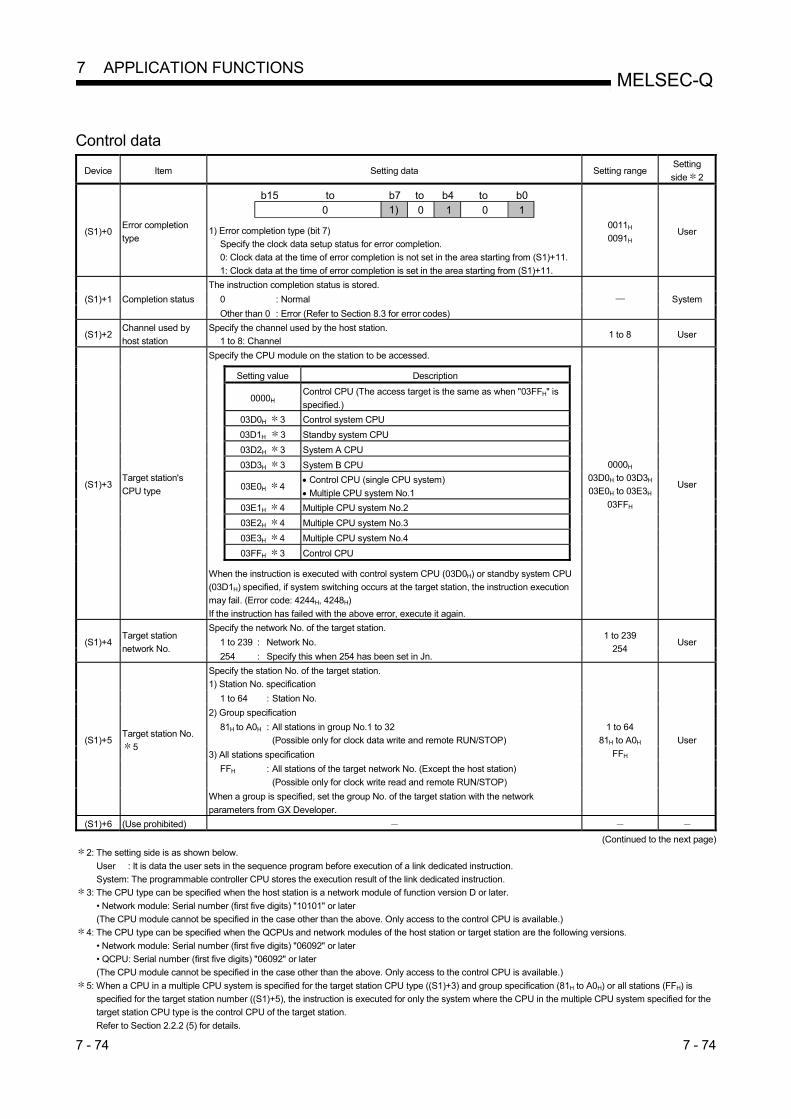
7 - 74 7 - 74
MELSEC-Q 7 APPLICATION FUNCTIONS
Control data
Device Item Setting data Setting range Setting
side 2
(S1)+0 Error completion
type
b15 b7 b0toto
1)b4to
0 10 0 1 1) Error completion type (bit 7)
Specify the clock data setup status for error completion.
0: Clock data at the time of error completion is not set in the area starting from (S1)+11.
1: Clock data at the time of error completion is set in the area starting from (S1)+11.
0011H
0091H User
(S1)+1 Completion status
The instruction completion status is stored.
System 0 : Normal
Other than 0 : Error (Refer to Section 8.3 for error codes)
(S1)+2 Channel used by
host station
Specify the channel used by the host station.
1 to 8: Channel 1 to 8 User
(S1)+3 Target station's
CPU type
Specify the CPU module on the station to be accessed.
0000H
03D0H to 03D3H
03E0H to 03E3H
03FFH
User
Setting value Description
0000H Control CPU (The access target is the same as when "03FFH" is
specified.)
03D0H 3 Control system CPU
03D1H
3 Standby system CPU
03D2H 3 System A CPU
03D3H 3 System B CPU
03E0H 4 Control CPU (single CPU system)
Multiple CPU system No.1
03E1H 4 Multiple CPU system No.2
03E2H 4 Multiple CPU system No.3
03E3H 4 Multiple CPU system No.4
03FFH 3 Control CPU When the instruction is executed with control system CPU (03D0H) or standby system CPU
(03D1H) specified, if system switching occurs at the target station, the instruction execution
may fail. (Error code: 4244H, 4248H)
If the instruction has failed with the above error, execute it again.
(S1)+4 Target station
network No.
Specify the network No. of the target station. 1 to 239
254 User 1 to 239 : Network No.
254 : Specify this when 254 has been set in Jn.
(S1)+5 Target station No.
5
Specify the station No. of the target station.
1) Station No. specification
1 to 64
81H to A0H
FFH
User
1 to 64 : Station No.
2) Group specification
81H to A0H : All stations in group No.1 to 32
(Possible only for clock data write and remote RUN/STOP)
3) All stations specification
FFH : All stations of the target network No. (Except the host station)
(Possible only for clock write read and remote RUN/STOP)
When a group is specified, set the group No. of the target station with the network
parameters from GX Developer.
(S1)+6 (Use prohibited)
(Continued to the next page)
2: The setting side is as shown below.
User : It is data the user sets in the sequence program before execution of a link dedicated instruction.
System: The programmable controller CPU stores the execution result of the link dedicated instruction.
3: The CPU type can be specified when the host station is a network module of function version D or later.
• Network module: Serial number (first five digits) "10101" or later
(The CPU module cannot be specified in the case other than the above. Only access to the control CPU is available.)
4: The CPU type can be specified when the QCPUs and network modules of the host station or target station are the following versions.
• Network module: Serial number (first five digits) "06092" or later
• QCPU: Serial number (first five digits) "06092" or later
(The CPU module cannot be specified in the case other than the above. Only access to the control CPU is available.)
5: When a CPU in a multiple CPU system is specified for the target station CPU type ((S1)+3) and group specification (81H to A0H) or all stations (FFH) is
specified for the target station number ((S1)+5), the instruction is executed for only the system where the CPU in the multiple CPU system specified for the
target station CPU type is the control CPU of the target station.
Refer to Section 2.2.2 (5) for details.
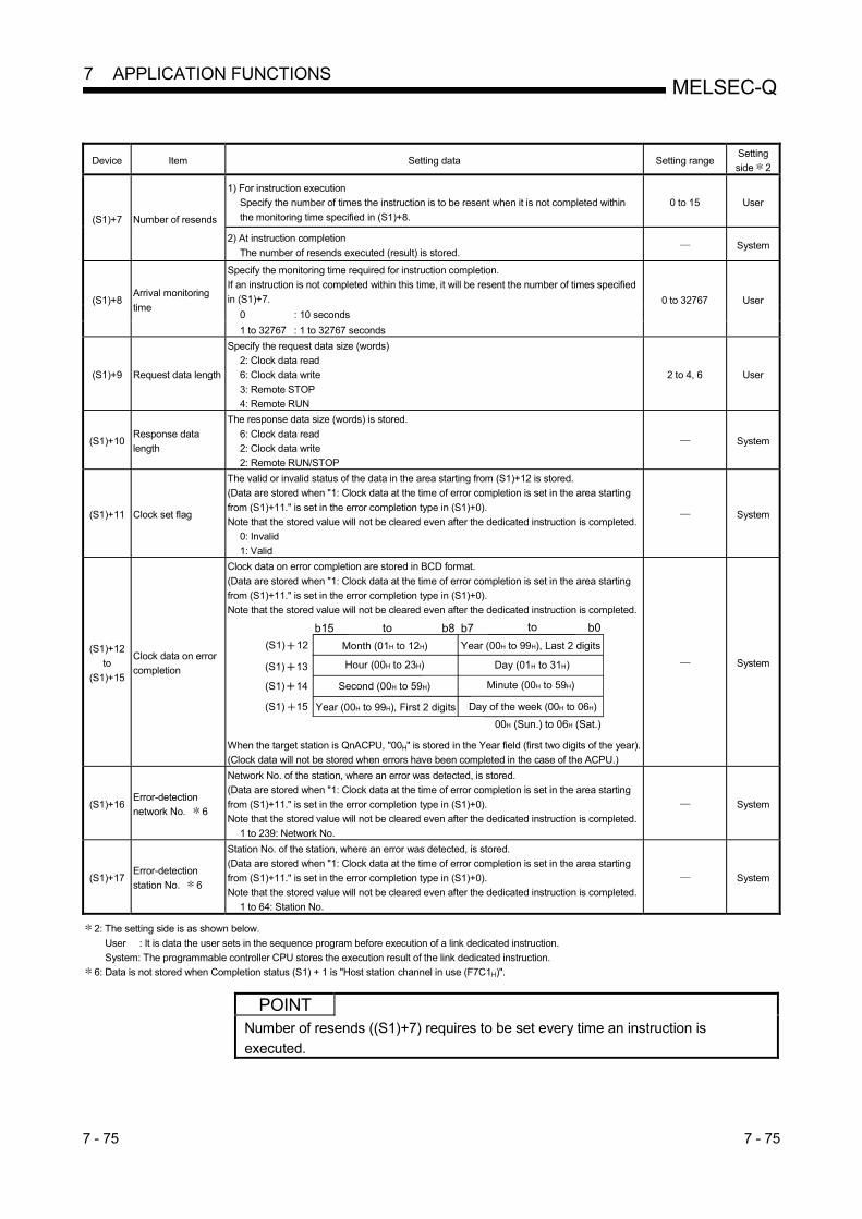
7 - 75 7 - 75
MELSEC-Q 7 APPLICATION FUNCTIONS
Device Item Setting data Setting range Setting
side 2
(S1)+7 Number of resends
1) For instruction execution
Specify the number of times the instruction is to be resent when it is not completed within
the monitoring time specified in (S1)+8.
0 to 15 User
2) At instruction completion
The number of resends executed (result) is stored. System
(S1)+8 Arrival monitoring
time
Specify the monitoring time required for instruction completion.
If an instruction is not completed within this time, it will be resent the number of times specified
in (S1)+7. 0 to 32767 User
0 : 10 seconds
1 to 32767 : 1 to 32767 seconds
(S1)+9 Request data length
Specify the request data size (words)
2: Clock data read
6: Clock data write
3: Remote STOP
4: Remote RUN
2 to 4, 6 User
(S1)+10 Response data
length
The response data size (words) is stored.
6: Clock data read
2: Clock data write
2: Remote RUN/STOP
System
(S1)+11 Clock set flag
The valid or invalid status of the data in the area starting from (S1)+12 is stored.
(Data are stored when "1: Clock data at the time of error completion is set in the area starting
from (S1)+11." is set in the error completion type in (S1)+0).
Note that the stored value will not be cleared even after the dedicated instruction is completed.
0: Invalid
1: Valid
System
(S1)+12
to
(S1)+15
Clock data on error
completion
Clock data on error completion are stored in BCD format.
(Data are stored when "1: Clock data at the time of error completion is set in the area starting
from (S1)+11." is set in the error completion type in (S1)+0).
Note that the stored value will not be cleared even after the dedicated instruction is completed.
(S1) 12
(S1) 13
(S1) 14
(S1) 15
Hour (00H to 23H) Day (01H to 31H)
b15 b7 b0toto b8
Second (00H to 59H) Minute (00H to 59H)
Year (00H to 99H), First 2 digits Day of the week (00H to 06H)
00H (Sun.) to 06H (Sat.)
Month (01H to 12H) Year (00H to 99H), Last 2 digits
When the target station is QnACPU, "00H" is stored in the Year field (first two digits of the year).
(Clock data will not be stored when errors have been completed in the case of the ACPU.)
System
(S1)+16 Error-detection
network No. 6
Network No. of the station, where an error was detected, is stored.
(Data are stored when "1: Clock data at the time of error completion is set in the area starting
from (S1)+11." is set in the error completion type in (S1)+0).
Note that the stored value will not be cleared even after the dedicated instruction is completed.
1 to 239: Network No.
System
(S1)+17 Error-detection
station No. 6
Station No. of the station, where an error was detected, is stored.
(Data are stored when "1: Clock data at the time of error completion is set in the area starting
from (S1)+11." is set in the error completion type in (S1)+0).
Note that the stored value will not be cleared even after the dedicated instruction is completed.
1 to 64: Station No.
System
2: The setting side is as shown below.
User : It is data the user sets in the sequence program before execution of a link dedicated instruction.
System: The programmable controller CPU stores the execution result of the link dedicated instruction.
6: Data is not stored when Completion status (S1) + 1 is "Host station channel in use (F7C1H)".
POINT
Number of resends ((S1)+7) requires to be set every time an instruction is
executed.

7 - 76 7 - 76
MELSEC-Q 7 APPLICATION FUNCTIONS
1) Request data (S2)/response data(D1) (for reading/writing the clock data) Request data (All set by the user)
Device Item Setting data Clock data
read
Clock data
write
(S2)+0 Request type
0001H: Clock data read
0011H: Clock data write (when station No. is specified in (S1)+5)
0031H: Clock data write (when all stations or a group is specified in (S1)+5)
(S2)+1 Sub-request type 0002H: Clock data read
0001H: Clock data write
(S2)+2 Change pattern, clock data to be
changed
1) Change pattern (bit 0 to 7)
Specify which items are to be written to the fields of (high byte of (S2)+2) to
((S2)+5).
0: Do not change
1: Change
2) Year data (bit 8 to 15)
Specify the year (last two digits) as a BCD code. b15 b0b1b2b3b4b5b6b7
Year (lower two digits)
DateHourMinuteSecondDay of the week
Month
b8Year (00H to 99H) 0
(S2) + 3
Clock data to be changed
(continued)
Specify new clock data as BCD codes.
(S2) 3
Minute (00H to 59H) Hour (00H to 23H)
b15 b7 b0toto b8
Second (00H to 59H)Day of week (00H to 06H)
00H (Sun.) to 06H (Sat.)
Day (01H to 31H) Month (01H to 12H)
(S2) 4
(S2) 5
(S2) + 4
(S2) + 5
: Set : Not set
POINT
In clock data writing by the REQ instruction, the first two digits of the year cannot be
changed.
To change the first two digits of the year data, modify the clock setting from GX
Developer or with the RTMWR instruction.
• Setting the clock on the stations on a network with GX Developer (Refer to
Section 7.4.6)
• Reading and writing clock data of other station CPU modules (Z(P).RTMRD,
Z(P).RTMWR) (Refer to (6) of this section)

7 - 77 7 - 77
MELSEC-Q 7 APPLICATION FUNCTIONS
Response data (All set by the system) 7
Device Item Setting data Clock data
read
Clock data
write
(D1)+0 Request type 0081H: Clock data read
0091H: Clock data write (when station No. is specified in (S1)+5)
(D1)+1 Sub-request type 0002H: Clock data read
0001H: Clock data write
(D1)+2
Clock data read
Clock data that have been read are stored as BCD codes.
(D1) 2
(D1) 3
(D1) 4
(D1) 5
Hour (00H to 23H) Day (01H to 31H)
b15 b7 b0toto b8
Second (00H to 59H) Minute (00H to 59H)
00H Day of week (00H to 06H)
00H (Sun.) to 06H (Sat.)
Month (01H to 12H) Year (00H to 99H), Last 2 digits
(D1)+3
(D1)+4
(D1)+5
: Stored : Not stored
7: When "all stations or a group (FFH or 81H to A0H)" is specified in Target station No. ((S1)+5), no response data will be stored.
POINT
Clock data cannot be written when system protect is applied to the target station
CPU module.

7 - 78 7 - 78
MELSEC-Q 7 APPLICATION FUNCTIONS
2) Request data (S2)/response data (D1) at remote RUN/STOP Request data (All set by the user)
Device Item Setting data Remote
RUN
Remote
STOP
(S2)+0 Request type 0010H: When station No. is specified in (S1)+5
0030H: When all stations or a group is specified in (S1)+5
(S2)+1 Sub-request type 0001H: Remote RUN
0002H: Remote STOP
(S2)+2 Operation mode
Specify whether to forcibly execute remote RUN/STOP or not.
The forced execution is a function that forces a station which has stopped by
remote STOP to RUN remotely from another station.
• For remote RUN
0001H: No forced execution
0003H: Forced execution
• For remote STOP
0003H (Fixed)
(S2)+3 Clear mode
Specify the CPU module device status for the case of remote RUN.
0000H: Do not clear (Note that the local devices are cleared.)
0001H: Clear (excluding the latch range)
0002H: Clear (including the latch range) Clear mode ((S2)+3) allows specification of the CPU module device clear
(initialization) process at the start of CPU module operation activated by remote
RUN.
The CPU module will perform the specified clear processing, and then it will run
according to the setting that can be confirmed by [PLC parameters] - [PLC file] -
[Initial Device value] in GX Developer.
: Set : Not set
Response data (All set by the system) 7
Device Item Setting data Remote
RUN
Remote
STOP
(D1)+0 Request type 0090H: When station No. is specified in (S1)+5
(D1)+1 Sub-request type 0001H: Remote RUN
0002H: Remote STOP
: Stored : Not stored
7: When "all stations or a group (FFH or 81H to A0H)" is specified in Target station No. ((S1)+5), no response data will be stored.
POINT
(1) Remote RUN/STOP is available when the RUN/STOP switch of the target
station CPU is set to "RUN".
(2) Remote RUN/STOP is not executable when system protect is applied to the
target station CPU module.
(3) When the target station CPU has been already in remote STOP/PAUSE state
by a request from another station, it cannot enter RUN mode if Mode ((S2+2)
is "No forced execution (0001H)".
(4) If the target station CPU module, for which remote STOP was performed, is
reset, the remote STOP information is erased.

7 - 79 7 - 79
MELSEC-Q 7 APPLICATION FUNCTIONS
(b) Instruction execution timing
1) Normal completion

7 - 80 7 - 80
MELSEC-Q 7 APPLICATION FUNCTIONS
2) Abnormal completion

7 - 81 7 - 81
MELSEC-Q 7 APPLICATION FUNCTIONS
(c) Program example
The following example shows a program that stops the CPU module of
station number 13 in network number 7.
When using the following program, provide interlocks in the program
referring to Section 6.1.

7 - 82 7 - 82
MELSEC-Q 7 APPLICATION FUNCTIONS
7.4.5 (4) Reading/writing word devices of other stations (J(P).ZNRD, J(P).ZNWR)
Target station
Refer to Section 6.3.
(a) Instruction format 1) J(P).ZNRD
This instruction reads data from devices of a programmable controller
on another station. (In units of words) Applicable device
Setting
data
Applicable device
Internal device File register
Link direct device
J \
Intelligent function
module device
U \G
Index register
Zn
Constant
K, H, $ Others
Bit Word Bit Word
n1 1
(S1) 2
(D1)
n2 1
(D2) 1: The number of digits of the bit device can be specified. (Number of digits of K, bit device start No.)
2: T, C, D or W can be used.
Instruction format
[Network No. specification] [Execution condition][Instruction symbol]
J.ZNRD
JP.ZNRD JnCommand
n1 (D1) n2 (D2)(S1)JP.ZNRD
J.ZNRD JnCommand
n1 (D1) n2 (D2)(S1)

7 - 83 7 - 83
MELSEC-Q 7 APPLICATION FUNCTIONS
Setting data
Setting data 3 4 Description Setting side 5 Data type
Jn Network No. of the target station (1 to 239) User Binary 16 bits
n1 Target station No. (1 to 64)
(S1) Target station's start device where data to be read are stored
Device name (D1)
The host station's start device where readout data will be stored
(A contiguous area for the read data length is required.)
n2
Read data length
When the target station is Q/R/L/QnA/AnUCPU: 1 to 230 words
When the target station is other than Q/R/L/QnA/AnUCPU: 1 to 32 words
User Binary 16 bits
(D2)
The own station's device that is turned on for one scan upon completion of the instruction
(D2)+1 also turns on if the instruction execution is failed, and the error code is stored in
the SW0031.
(For the error code, refer to Section 8.3.)
System Bit
3: Local devices and file registers for each program cannot be used as devices in setting data.
4: In addition to the setting data, the ZNRD instruction is executed using the following fixed values.
Channel used by host station: Channel 1
Arrival monitoring time (monitoring time until instruction completion): 10 seconds
Number of resends for arrival monitoring timeout: 0 times
5: The setting side is as shown below.
User : It is data the user sets in the sequence program before execution of a link dedicated instruction.
System: The programmable controller CPU stores the execution result of the link dedicated instruction.
POINT (1) Specify the device of the other station CPU module to be read with the ZNRD
instruction within the range available for the host CPU module.
(Head device No. (S1) of read target of other station CPU module) + (Number
of read points - 1) (Last device No. of host CPU module )
: Last device number at the host CPU module having the same device
name as (S1)
(2) When a CPU module on another station read by the ZNRD instruction is an
A2UCPU(S1), A3UCPU, A4UCPU, A2ASCPU(S1), or A2USCPU(S1), use
the CPU module with the following version or later.
• A2UCPU(S1), A3UCPU, A4UCPU: Version AY (manufactured since July,
1995) or later
• A2ASCPU(S1), A2USCPU(S1): Version CP (manufactured since July,
1995) or later
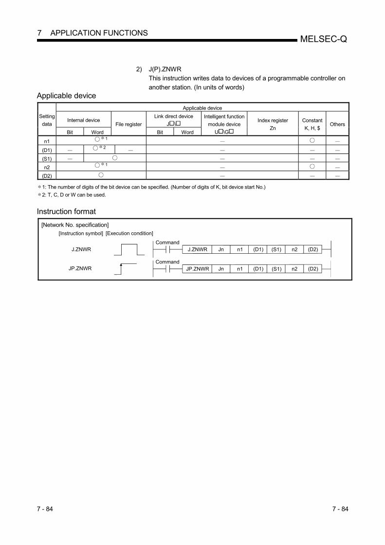
7 - 84 7 - 84
MELSEC-Q 7 APPLICATION FUNCTIONS
2) J(P).ZNWR
This instruction writes data to devices of a programmable controller on
another station. (In units of words) Applicable device
Setting
data
Applicable device
Internal device File register
Link direct device
J \
Intelligent function
module device
U \G
Index register
Zn
Constant
K, H, $ Others
Bit Word Bit Word
n1 1
(D1) 2
(S1)
n2 1
(D2) 1: The number of digits of the bit device can be specified. (Number of digits of K, bit device start No.)
2: T, C, D or W can be used.
Instruction format
[Network No. specification] [Execution condition][Instruction symbol]
J.ZNWR
JP.ZNWR JnCommand
n1 (S1) n2 (D2)(D1)JP.ZNWR
J.ZNWR JnCommand
n1 (S1) n2 (D2)(D1)

7 - 85 7 - 85
MELSEC-Q 7 APPLICATION FUNCTIONS
Setting data
Setting data 3 4 Description Setting side 5 Data type
Jn Network No. of the target station (1 to 239)
User Binary 16 bits n1
Target station No.
Specify the station No. of the target station.
1) Station No. specification
1 to 64: Station No.
2) Group specification
81H to A0H: All stations of a group (No.1 to 32)
3) All stations specification
FFH: All stations of the target network No. (Except the host station)
When a group is specified, set the group No. of the target station with the network
parameters from GX Developer.
(D1) Target station's start device to which data are to be written.
(A contiguous area for the write data length is required.) — Device name
(S1) The host station's start device where write data are stored.
n2
Write data length
When the target station is Q/R/L/QnA/AnUCPU: 1 to 230 words
When the target station is other than Q/R/L/QnA/AnUCPU: 1 to 32 words
User Binary 16 bits
(D2)
The host station's device that is turned on for one scan upon completion of the instruction
(D2)+1 also turns on if the instruction execution is failed, and the error code is stored in
the SW0033.
(For the error code, refer to Section 8.3.)
System Bit
3: Local devices and file registers for each program cannot be used as devices in setting data.
4: The ZNWR instruction is executed using the following fixed values as well as setting data.
Channel used by host station: Channel 2
Arrival monitoring time (monitoring time until instruction completion): 10 seconds
Number of resends for arrival monitoring timeout: 0 times
5: The setting side is as shown below.
User : It is data the user sets in the sequence program before execution of a link dedicated instruction.
System: The programmable controller CPU stores the execution result of the link dedicated instruction.
POINT
(1) Specify the device of the other station CPU module to be written with the
ZNWR instruction within the range available for the host CPU module.
(Head device No. (D1) of write target of other station CPU module) +
(Number of write points - 1) (Last device No. of host CPU module )
: Last device number at the host CPU module having the same device
name as (D1)
(2) When a CPU module on another station written by the ZNWR instruction is an
A2UCPU(S1), A3UCPU, A4UCPU, A2ASCPU(S1), or A2USCPU(S1), use
the CPU module with the following version or later.
• A2UCPU(S1), A3UCPU, A4UCPU: Version AY (manufactured since July,
1995) or later
• A2ASCPU(S1), A2USCPU(S1): Version CP (manufactured since July,
1995) or later

7 - 86 7 - 86
MELSEC-Q 7 APPLICATION FUNCTIONS
(b) Instruction execution timing 1) Normal completion
[ZNRD instruction]
Network module
Network module
0 ENDSequence scan 0 END 0 END 0 END 0 END
Read command
ZNRD
One scan
Target station CPU
0 ENDSequence scan END 0 END0 END
100
0 END 0
100
OFF
Host CPU
Channel 1(fixed)
Read data storage device(Device designated in (D1))
Read completion device(Device at (D2)+1)
Read completion device(Device designated in (D2))
Read data storage device(Device designated in (S1))
OFF
OFF OFFON
OFFON

7 - 87 7 - 87
MELSEC-Q 7 APPLICATION FUNCTIONS
[ZNWR instruction]
Network module
Network module
0 ENDSequence scan 0 END 0 END 0 END 0 END
Write command
ZNWR
One scan
Target station CPU0 ENDSequence scan END 0 END0 END
3000
0 END 0
3000
Host CPU
Channel 2 (fixed)
OFF
OFF
OFF OFFON
OFFON
Write completion device(Device designated in (D2))
Write completion device(Device at (D2)+1)
Write data storage device(Device designated in (S1))
Write data storage device(Device designated in (D1))

7 - 88 7 - 88
MELSEC-Q 7 APPLICATION FUNCTIONS
2) Abnormal completion
[ZNRD instruction]
OFF
OFF
OFF OFFON
OFFON
OFFON
Read command
Network module
0 ENDSequence scan 0 END 0 END 0 END 0 END
ZNRD
One scan
SW0031 Error code
Host CPU
Channel 1(fixed)
Read completion device(Device designated in (D2))
Read completion device(Device at (D2)+1)
Target stationerror
[ZNWR instruction]
OFF
OFF
OFF OFF
OFFON
OFFON
Write command
Network module
0 ENDSequence scan 0 END 0 END 0 END 0 END
ZNWR
One scan
SW0033 Error code
3000
Host CPU
Channel 2(fixed)
Write completion device(Device designated in (D2))
Write completion device(Device at (D2)+1)
Write data storage device(Device designated in (S1))
Target stationerror
ON
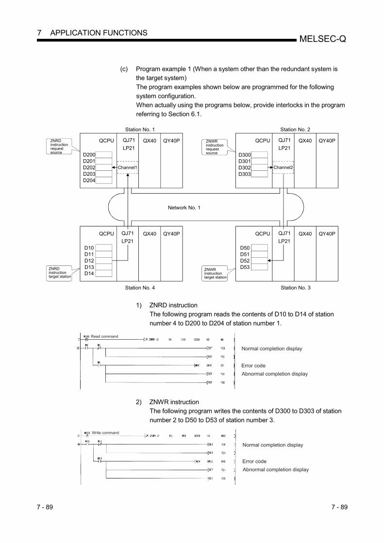
7 - 89 7 - 89
MELSEC-Q 7 APPLICATION FUNCTIONS
(c) Program example 1 (When a system other than the redundant system is
the target system)
The program examples shown below are programmed for the following
system configuration.
When actually using the programs below, provide interlocks in the program
referring to Section 6.1.
QJ71
LP21
ZNRD instruction request source
QY40PQX40QJ71
LP21D200D201D202D203D204
ZNRD instructiontarget station
D10D11D12D13D14
Station No. 1
Station No. 4
Network No. 1
ZNWR instruction request source
QJ71
LP21D300D301D302D303
ZNWR instruction target station
D50D51D52D53
QJ71
LP21
Station No. 2
Station No. 3
QCPU QCPU
QCPU QCPUQX40 QY40P
QY40PQX40
QY40PQX40
Channel1 Channel2
1) ZNRD instruction
The following program reads the contents of D10 to D14 of station
number 4 to D200 to D204 of station number 1.
2) ZNWR instruction
The following program writes the contents of D300 to D303 of station
number 2 to D50 to D53 of station number 3.
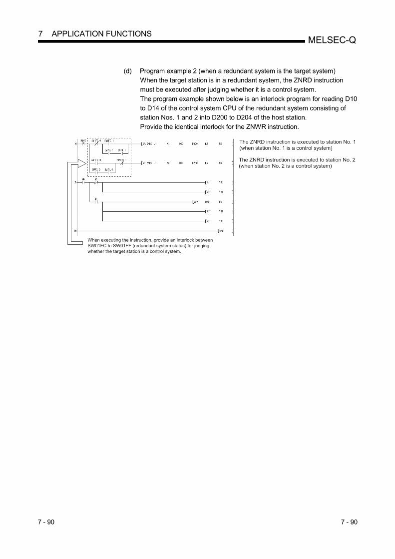
7 - 90 7 - 90
MELSEC-Q 7 APPLICATION FUNCTIONS
(d) Program example 2 (when a redundant system is the target system)
When the target station is in a redundant system, the ZNRD instruction
must be executed after judging whether it is a control system.
The program example shown below is an interlock program for reading D10
to D14 of the control system CPU of the redundant system consisting of
station Nos. 1 and 2 into D200 to D204 of the host station.
Provide the identical interlock for the ZNWR instruction.

7 - 91 7 - 91
MELSEC-Q 7 APPLICATION FUNCTIONS
7.4.5 (5) Remote RUN/Remote STOP (Z(P).RRUN, Z(P).RSTOP)
Target station
Refer to Section 6.3.
(a) Instruction format
1) Z(P).RRUN
This instruction is used to remotely stop a programmable controller on
another station. Applicable device
Setting
data
Applicable device
Internal device File register
Link direct device
J \
Intelligent function
module device
U \G
Index register
Zn
Constant
K, H, $ Others
Bit Word Bit Word
n1 n2 n3 n4 (D)
Instruction format
[Network No. specification] [Execution condition][Instruction symbol]
Z.RRUN
ZP.RRUNCommand
n1 n3 n4 (D)n2"Jn"ZP.RRUN
Commandn1 n3 n4 (D)n2Z.RRUN "Jn"
[Network module starting I/O number specification]
[Execution condition][Instruction symbol]
Z.RRUN
ZP.RRUNCommand
n1 n3 n4 (D)n2"Un"ZP.RRUN
Commandn1 n3 n4 (D)n2Z.RRUN "Un"
: If the host is the Basic model QCPU (function version B or later) or Universal model QCPU, " "(double quotation) for the
first argument can be omitted.

7 - 92 7 - 92
MELSEC-Q 7 APPLICATION FUNCTIONS
Setting data
Setting data 1 Description Setting side 2 Data type
"Jn"/Jn Network No. of the target station (1 to 239, 254)
254: The network specified in Valid module during other station access
User
String/Binary 16 bits
"Un"/Un Start I/O number of the host station's network module
(00 to FEH: The higher two digits of the 3-digit I/O number)
n1
Channel used by host station (1 to 8)
Specify the channel used by the host station.
Specify the channel used by host station that is the same as the one used for the RSTOP
instruction.
Binary 16 bits
n2 3
Target station No.
Specify the station No. of the target station.
1) Station No. specification
1 to 64: Station No.
2) Group specification
81H to A0H: All stations of a group (No.1 to 32)
3) All stations specification
FFH: All stations of the target network No. (Except the host station)
When a group is specified, set the group No. of the target station with the network
parameters from GX Developer.
n3
Target station's CPU type
Specify the CPU module on the station to be accessed.
Setting value Description
0000H 4 Control CPU (The access target is the same as when "03FFH"
is specified.)
03D0H 4 Control system CPU
03D1H 4 Standby system CPU
03D2H 4 System A CPU
03D3H 4 System B CPU
03E0H 5 Control CPU (single CPU system)
Multiple CPU system No.1
03E1H 5 Multiple CPU system No.2
03E2H 5 Multiple CPU system No.3
03E3H 5 Multiple CPU system No.4
03FFH Control CPU When the instruction is executed with control system CPU (03D0H) or standby system
CPU (03D1H) specified, if system switching occurs at the target station, the instruction
execution may fail. (Error code: 4244H, 4248H)
If the instruction has failed with the above error, execute it again.
n4
Mode
Specify options for the operation mode and clear mode.
2) 1)
tob15 b8 b7to b4 b3 to b00
1) Operation mode
Specify whether to forcibly execute remote RUN or not.
1H: No forced execution
3H: Forced execution
The forced execution is a function that forces a station, which has stopped by remote
STOP, to RUN remotely from another station.
2) Clear mode
Specify the CPU module device status for the case of remote RUN.
0H: Do not clear (Note that the local devices are cleared.)
1H: Clear (excluding the latch range)
2H: Clear (including the latch range)
Clear mode allows specification of the CPU module device clear (initialization) process at
the start of CPU module operation activated by remote RUN.
The CPU module will perform the specified clear processing, and then it will run according
to the setting that can be confirmed by [PLC parameters] - [PLC file] - [Initial Device value]
in GX Developer.
(D)
The host station's device that is turned on for one scan upon completion of the instruction
(D1)+1 also turns on if the instruction execution is failed, and the error code is stored in
the SW0031 to SW003F.
(For the error code, refer to Section 8.3.)
System Bit

7 - 93 7 - 93
MELSEC-Q 7 APPLICATION FUNCTIONS
1: Local devices and file registers for each program cannot be used as devices in setting data.
2: The setting side is as shown below.
User : It is data the user sets in the sequence program before execution of a link dedicated instruction.
System: The programmable controller CPU stores the execution result of the link dedicated instruction.
3: When a CPU in a multiple CPU system is specified for the target station CPU type ((S1)+3) and group specification (81H to A0H) or all stations (FFH) is
specified for the target station number ((S1)+5), the instruction is executed for only the system where the CPU in the multiple CPU system specified for the
target station CPU type is the control CPU of the target station.
Refer to Section 2.2.2 (5) for details.
4: The CPU type can be specified when the host station is a network module of which function version is either D or later or the following.
• Network module: Serial number (first five digits) "10101" or later
(The CPU module cannot be specified in the case other than the above. Only access to the control CPU is available.)
5: The CPU type can be specified when the QCPUs of the host station and target station are the following versions.
• QCPU: Serial number (first five digits) "06092" or later
(The CPU module cannot be specified in the case other than the above. Only access to the control CPU is available.)
POINT
(1) Remote RUN is available when the RUN/STOP switch of the target station
CPU is set to "RUN".
(2) Remote RUN is not executable when system protect is applied to the target
station CPU module.
(3) When the target station CPU has been already in remote STOP/PAUSE state
by a request from another station, it cannot enter RUN mode if Mode (n4) is
"No forced execution (0001H)".

7 - 94 7 - 94
MELSEC-Q 7 APPLICATION FUNCTIONS
2) Z(P).RSTOP
This instruction is used to remotely stop a programmable controller on
another station. Applicable device
Setting
data
Applicable device
Internal device File register
Link direct device
J \
Intelligent function
module device
U \G
Index register
Zn
Constant
K, H, $ Others
Bit Word Bit Word
n1 n2 n3 n4 (D)
Instruction format
[Network No. specification] [Execution condition][Instruction symbol]
Z.RSTOP
ZP.RSTOPCommand
n1 n3 n4 (D)n2"Jn"ZP.RSTOP
Commandn1 n3 n4 (D)n2Z.RSTOP "Jn"
[Network module starting I/O number specification]
[Execution condition][Instruction symbol]
Z.RSTOP
ZP.RSTOPCommand
n1 n3 n4 (D)n2"Un"ZP.RSTOP
Command
n1 n3 n4 (D)n2Z.RSTOP "Un"
: If the host station is the Basic model QCPU (function version B or later) or Universal model QCPU, " "(double quotation)
for the first argument can be omitted.

7 - 95 7 - 95
MELSEC-Q 7 APPLICATION FUNCTIONS
Setting data
Setting data 1 Description Setting side 2 Data type
"Jn"/Jn Network No. of the target station (1 to 239, 254)
254: The network specified in Valid module during other station access
User
String/Binary 16 bits
"Un"/Un Start I/O number of the host station's network module
(00 to FEH: The higher two digits of the 3-digit I/O number)
n1 Channel used by host station (1 to 8)
Specify the channel used by the host station.
Binary 16 bits
n23
Target station No.
Specify the station No. of the target station.
1) Station No. specification
1 to 64: Station No.
2) Group specification
81H to A0H: All stations of a group (No.1 to 32)
3) All stations specification
FFH: All stations of the target network No. (Except the host station)
When a group is specified, set the group No. of the target station with the network
parameters from GX Developer.
n3
Target station's CPU type
Specify the CPU module on the station to be accessed.
Setting value Description
0000H 4 Control CPU (The access target is the same as when "03FFH"
is specified.)
03D0H 4 Control system CPU
03D1H 4 Standby system CPU
03D2H 4 System A CPU
03D3H 4 System B CPU
03E0H 5 Control CPU (single CPU system)
Multiple CPU system No.1
03E1H 5 Multiple CPU system No.2
03E2H 5 Multiple CPU system No.3
03E3H 5 Multiple CPU system No.4
03FFH Control CPU When the instruction is executed with control system CPU (03D0H) or standby system
CPU (03D1H) specified, if system switching occurs at the target station, the instruction
execution may fail. (Error code: 4244H, 4248H)
If the instruction has failed with the above error, execute it again.
n4
Operation mode
1H: Fixed
1)
b15 to b4 b3 to b0
0
(D)
The host station's device that is turned on for one scan upon completion of the instruction
(D)+1 also turns on if instruction execution is failed, and the error code is stored in the
SW0031 to SW003F.
(For the error code, refer to Section 8.3.)
System Bit
1: Local devices and file registers for each program cannot be used as devices in setting data.
2: The setting side is as shown below.
User : It is data the user sets in the sequence program before execution of a link dedicated instruction.
System: The programmable controller CPU stores the execution result of the link dedicated instruction.
3: When a CPU in a multiple CPU system is specified for the target station CPU type ((S1)+3) and group specification (81H to A0H) or all stations (FFH) is
specified for the target station number ((S1)+5), the instruction is executed for only the system where the CPU in the multiple CPU system specified for the
target station CPU type is the control CPU of the target station.
Refer to Section 2.2.2 (5) for details.
4: The CPU type can be specified when the host station is a network module of which function version is either D or later or the following.
• Network module: Serial number (first five digits) "10101" or later
(The CPU module cannot be specified in the case other than the above. Only access to the control CPU is available.)
5: The CPU type can be specified when the QCPUs of the host station and target station are the following versions.
• QCPU: Serial number (first five digits) "06092" or later
(The CPU module cannot be specified in the case other than the above. Only access to the control CPU is available.)

7 - 96 7 - 96
MELSEC-Q 7 APPLICATION FUNCTIONS
POINT
(1) Remote STOP is available when the RUN/STOP switch of the target station
CPU is set to "RUN".
(2) Remote STOP is not executable when system protect is applied to the target
station CPU.
(3) If the target station CPU, for which remote STOP was performed, is reset, the
remote STOP information is erased.
(b) Instruction execution timing 1) Normal completion
[RRUN instruction]
OFF
OFF
OFF OFFON
OFFON
Network module
Network module
Channel 1
0 ENDSequence scan 0 END 0 END 0 END 0 END
Execution command
RRUN
One scan
Sequence scan END 0 END0 END 0
Remote RUN
Host CPU
Target station’s CPU
When stopped When stopped
Execution completion device(device specified with (D))
Execution completion device(device specified with(D)+1)

7 - 97 7 - 97
MELSEC-Q 7 APPLICATION FUNCTIONS
[RSTOP instruction]
OFF
OFF
OFF OFFON
OFFON
0 END 0 END 0 END 0 END 0 END
RSTOP
0 END 0 END
Network module
Network module
Channel 1
Sequence scan
Execution command
One scan
Sequence scan
Host CPU
Target station’s CPU
When stopped
Remote STOP
Execution completion device(device specified with (D))
Execution completion device(device specified with(D)+1)
According to the system organization, sequence scan time, etc.,
several scans will be run until the sequence scan STOP instruction
is given.

7 - 98 7 - 98
MELSEC-Q 7 APPLICATION FUNCTIONS
2) Abnormal completion
[RRUN instruction]
0 END 0 END 0 END 0 END 0 END
SW0031
Target stationerror
Error code
Network module Channel 1
Sequence scan
Execution command
One scan
Host CPU
RRUN
OFF
OFF
OFF OFFON
OFFON
OFFON
Execution completion device(device specified with (D))
Execution completion device(device specified with (D)+1)
[RSTOP instruction]
OFF
OFF
OFF OFFON
OFFON
OFFON
0 END 0 END 0 END 0 END 0 END
RSTOP
SW0031
Target stationerror
Error code
Network module Channel 1
Sequence scan
Execution command
One scan
Host CPU Execution completion device(device specified with (D))
Execution completion device(device specified with (D)+1)
POINT
The error code will be stored in SW0031 to SW003F depending on the channel
number in use. For details, refer to section 8.3 (3).

7 - 99 7 - 99
MELSEC-Q 7 APPLICATION FUNCTIONS
(c) Program examples
The program examples shown below are programmed for the following
system configuration.
When actually using the programs below, provide interlocks in the program
referring to Section 6.1.
QCPU QX40 QY40P QJ71LP21
1
QCPU QX40 QY40P QJ71LP21
1
QCPU QX40 QY40P QJ71LP21
QCPU QX40 QY40P QJ71LP21STOP
RUN STOP
RUN
Channel Channel
RRUNinstructiontarget station
RSTOPinstructiontarget station
Station No. 1
Station No. 4
Network No. 1
Station No. 2
Station No. 3
RRUNinstructionrequest source
RSTOPinstructionrequest source
1) RRUN instruction
A program to execute the remote RUN instruction using channel 1 for
the station No.4 control CPU is shown below.
M0 is used as the completion device.
2) RSTOP instruction
A program to execute the remote STOP instruction using channel 1 for
the station No.3 control CPU is shown below.
M0 is used as the completion device.

7 - 100 7 - 100
MELSEC-Q 7 APPLICATION FUNCTIONS
7.4.5 (6) Reading and writing clock data of other station CPU modules (Z(P).RTMRD,
Z(P).RTMWR)
Target station
Refer to Section 6.3.
(a) Instruction format
1) Z(P).RTMRD
This instruction is used to read clock data from a programmable
controller on another station. Applicable device
Setting
data
Applicable device
Internal device File register
Link direct device
J \
Intelligent function
module device
U \G
Index register
Zn
Constant
K, H, $ Others
Bit Word Bit Word
n1 n2 n3
(D1) (D2)
Instruction format
[Network No. specification] [Execution condition][Instruction symbol]
Z.RTMRD
ZP.RTMRD
Commandn1 n3 (D1) (D2)n2"Jn"ZP.RTMRD
Commandn1 n3 (D1) (D2)n2Z.RTMRD "Jn"
[Network module starting I/O number specification]
[Execution condition][Instruction symbol]
Z.RTMRD
ZP.RTMRD
Command
n1 n3 (D1) (D2)n2"Un"ZP.RTMRD
Command
n1 n3 (D1) (D2)n2Z.RTMRD "Un"
: If the host is the Basic model QCPU (function version B or later) or Universal model QCPU, " "(double quotation) for the
first argument can be omitted.

7 - 101 7 - 101
MELSEC-Q 7 APPLICATION FUNCTIONS
Setting data
Setting data 1 Description Setting side 2 Data type
"Jn"/Jn Network No. of the target station (1 to 239, 254)
254: The network specified in Valid module during other station access
User
String/Binary 16 bits
"Un"/Un Start I/O number of the host station's network module
(00 to FEH: The higher two digits of the 3-digit I/O number)
n1 Channel used by host station (1 to 8)
Specify the channel used by the host station.
Binary 16 bits
n2 Target station No. (1 to 64)
n3
Target station's CPU type
Specify the CPU module on the station to be accessed.
Setting value Description
0000H 3 Control CPU (The access target is the same as when "03FFH"
is specified.)
03D0H 3 Control system CPU
03D1H 3 Standby system CPU
03D2H 3 System A CPU
03D3H 3 System B CPU
03E0H Control CPU (single CPU system)
Multiple CPU system No.1
03E1H Multiple CPU system No.2
03E2H Multiple CPU system No.3
03E3H Multiple CPU system No.4
03FFH Control CPU When the instruction is executed with control system CPU (03D0H) or standby system
CPU (03D1H) specified, if system switching occurs at the target station, the instruction
execution may fail. (Error code: 4244H, 4248H)
If the instruction has failed with the above error, execute it again.
(D1) Start device of the host station, in which clock data are stored
(Refer to the clock data table.)
System
Device name
(D2)
The host station's device that is turned on for one scan upon completion of the instruction
(D2)+1 also turns on if the instruction execution is failed, and the error code is stored in
the SW0031 to SW003F.
(For the error code, refer to Section 8.3.)
Bit
1: Local devices and file registers for each program cannot be used as devices in setting data.
2: The setting side is as shown below.
User : It is data the user sets in the sequence program before execution of a link dedicated instruction.
System: The programmable controller CPU stores the execution result of the link dedicated instruction.
3: The CPU type can be specified when the host station is a network module of which function version is either D or later or the following
Network module: Serial number (first five digits) "10101" or later
(The CPU module cannot be specified in the case other than the above. Only access to the control CPU is available.)
Clock data
Device Item Setting data
(D1)+0
Clock data
Clock data that have been read are stored as BCD codes. (all set by the system)
The range available for 4-digit year reading is 1980 to 2079.
(D1) 0
(D1) 1
(D1) 2
(D1) 3
Hour (00H to 23H)Day (01H to 31H)
b15 b7 b0toto b8
Second (00H to 59H)Minute (00H to 59H)
Day of week (00H to 06H)
00H (Sun.) to 06H (Sat.)
Month (01H to 12H)Year (00H to 99H), Last 2 digits
Year (19H to 20H), First 2 digits
(D1)+1
(D1)+2
(D1)+3

7 - 102 7 - 102
MELSEC-Q 7 APPLICATION FUNCTIONS
2) Z(P).RTMWR
This instruction is used to write clock data to a programmable controller
on another station. Applicable device
Setting
data
Applicable device
Internal device File register
Link direct device
J \
Intelligent function
module device
U \G
Index register
Zn
Constant
K, H, $ Others
Bit Word Bit Word
n1 n2 n3
(D1) (D2)
Instruction format
[Network No. specification] [Execution condition][Instruction symbol]
Z.RTMWR
ZP.RTMWRCommand
n1 n3 (D1) (D2)n2"Jn"ZP.RTMWR
Commandn1 n3 (D1) (D2)n2Z.RTMWR "Jn"
[Network module starting I/O number specification]
[Execution condition][Instruction symbol]
Z.RTMWR
ZP.RTMWR
Commandn1 n3 (D1) (D2)n2"Un"ZP.RTMWR
Commandn1 n3 (D1) (D2)n2Z.RTMWR "Un"
: If the host station is the Basic model QCPU (function version B or later), Universal model QCPU, or safety CPU, " "
(double quotation) of the first argument can be omitted.

7 - 103 7 - 103
MELSEC-Q 7 APPLICATION FUNCTIONS
Setting data
Setting data 1 Description Setting side 2 Data type
"Jn"/Jn Network No. of the target station (1 to 239, 254)
254: The network specified in Valid module during other station access
User
String/Binary 16 bits
"Un"/Un Start I/O number of the host station's network module
(00 to FEH: The higher two digits of the 3-digit I/O number)
n1 Channel used by host station (1 to 8)
Specify the channel used by the host station.
Binary 16 bits
n2 3
Target station No.
Specify the station No. of the target station.
1) Station No. specification
1 to 64: Station No.
2) Group specification
81H to A0H: All stations of a group (No.1 to 32)
3) All stations specification
FFH: All stations of the target network No. (Except the host station)
When a group is specified, set the group No. of the target station with the network
parameters from GX Developer.
n3
Target station's CPU type
Specify the CPU module on the station to be accessed.
Setting value Description
0000H 4 Control CPU (The access target is the same as when "03FFH"
is specified.)
03D0H 4 Control system CPU
03D1H 4 Standby system CPU
03D2H 4 System A CPU
03D3H 4 System B CPU
03E0H 5 Control CPU (single CPU system)
Multiple CPU system No.1
03E1H 5 Multiple CPU system No.2
03E2H 5 Multiple CPU system No.3
03E3H 5 Multiple CPU system No.4
03FFH Control CPU When the instruction is executed with control system CPU (03D0H) or standby system
CPU (03D1H) specified, if system switching occurs at the target station, the instruction
execution may fail. (Error code: 4244H, 4248H)
If the instruction has failed with the above error, execute it again.
(D1) Start device of the host station, in which clock data are stored
(Refer to the clock data table.) Device name
(D2)
The host station's device that is turned on for one scan upon completion of the instruction
(D2)+1 also turns on if the instruction execution is failed, and the error code is stored in
the SW0031 to SW003F.
(For the error code, refer to Section 8.3.)
System Bit
1: Local devices and file registers for each program cannot be used as devices in setting data.
2: The setting side is as shown below.
User : It is data the user sets in the sequence program before execution of a link dedicated instruction.
System: The programmable controller CPU stores the execution result of the link dedicated instruction.
3: When a CPU in a multiple CPU system is specified for the target station CPU type ((S1)+3) and group specification (81H to A0H) or all stations (FFH) is
specified for the target station number ((S1)+5), the instruction is executed for only the system where the CPU in the multiple CPU system specified for the
target station CPU type is the control CPU of the target station.
Refer to Section 2.2.2 (5) for details.
4: The CPU type can be specified when the host station is a network module of function version D or later.
• Net work module: Serial number (first five digits) "10101" or later
(The CPU module cannot be specified in the case other than the above. Only access to the control CPU is available.)
5: The CPU type can be specified when the QCPUs of the host station and target station are the following versions.
• QCPU: Serial number (first five digits) "06092" or later
(The CPU module cannot be specified in the case other than the above. Only access to the control CPU is available.)

7 - 104 7 - 104
MELSEC-Q 7 APPLICATION FUNCTIONS
Clock data
Device Item Setting data
(D1)+0 Change pattern
In (D1)+1 to (D1)+4, specify data to be changed. (all set by the user)
0: Do not change
1: Change b15 b8to b7 b6 b5 b4 b3 b2 b1 b0
Year (lower two digits)MonthDateHourMinutesSecondsDayYear (higher two digits)
0 0to
(D1)+1
Clock data
Specify new clock data as BCD codes.
The range available for 4-digit year writing is 1980 to 2079.
(D1) 1
(D1) 2
(D1) 3
(D1) 4
Hour (00H to 23H)Day (01H to 31H)
b15 b7 b0toto b8
Second (00H to 59H)Minute (00H to 59H)
Day of week (00H to 06H)
00H (Sun.) to 06H (Sat.)
Month (01H to 12H)Year (00H to 99H), Last 2 digits
Year (19H to 20H), First 2 digits
(D1)+2
(D1)+3
(D1)+4
POINT
Clock data cannot be written when system protect is applied to the target station
CPU.

7 - 105 7 - 105
MELSEC-Q 7 APPLICATION FUNCTIONS
(b) Instruction execution timing 1) Normal completion
[RTMRD instruction]
OFF
OFF
OFF OFFON
OFFON
0 END 0 END 0 END 0 END 0 END
Read command
RTMRD
0 END END 0 END0 END
Clock data
0 END 0
Clock dataClock data
Network module
Network module
Channel 1
Sequence scan
One scan
Sequence scan
Host CPU
Target station’s CPU
Read completion device(device specified with (D2))
Read completion device(device specified with (D2)+1)
Device for storing the readclock data (device specified with (D1))

7 - 106 7 - 106
MELSEC-Q 7 APPLICATION FUNCTIONS
[RTMWR instruction]
OFF
OFF
OFF OFFON
OFFON
0 END 0 END 0 END 0 END 0 END
Write command
RTMWR
0 END END 0 END0 END 0 END 0
Clock data
Clock dataClock data
Network module
Network module
Channel 1
Sequence scan
One scan
Sequence scan
Host CPU
Target station’s CPU
Write completion device(device specified with (D2))
Write completion device(device specified with (D2)+1)
Device for storing the writtenclock data (device specified with (D1))

7 - 107 7 - 107
MELSEC-Q 7 APPLICATION FUNCTIONS
2) Abnormal completion
[RTMRD instruction]
OFF
OFF
OFF OFFON
OFFON
OFFON
0 END 0 END 0 END 0 END 0 END
RTMRD
SW0031
Read command
Network module Channel 1
Sequence scan
One scan
Host CPU
Target stationerror
Error code
Read completion device(device specified with (D2)+1)
Read completion device(device specified with (D2))
[RTMWR instruction]
OFF
OFF
OFF OFFON
OFFON
OFFON
0 END 0 END 0 END 0 END 0 END
RTMWR
Write command
Clock data
Network module Channel 1
Sequence scan
One scan
Host CPU
Target stationerror
Error code
Write completion device(device specified with (D2))
Write completion device(device specified with (D2)+1)
Device for storing the writtenclock data(device specified with (D1))
SW0031
POINT
The error code will be stored in SW0031 to SW003F depending on the channel
number in use. For details, refer to section 8.3 (3).

7 - 108 7 - 108
MELSEC-Q 7 APPLICATION FUNCTIONS
(c) Program examples
The program examples shown below are programmed for the following
system configuration.
When actually using the programs below, interlock the programs referring
Section 6.1.
1) RTMRD instruction
A program to execute the clock data read instruction with the use of
channel 1 for the station No.4 control CPU and storing the result in D0
is shown below.
M0 is used as the completion device.
2) RTMWR instruction
A program for writing the clock data stored in the host's D0 with the
use of channel 1 into the station No.3 control CPU is shown below.
M0 is used as the completion device.

7 - 109 7 - 109
MELSEC-Q 7 APPLICATION FUNCTIONS
7.4.6 Setting the clock to stations on a network with GX Developer
The clock can be set on the CPU modules that are connected on a network using GX Developer. By specifying the execution destination to all stations or a group, the clock can be set on multiple stations at the same time. Select [Online] [Set time] on the GX Developer screen to display the following screen. First, check the connection destination and set the clock. Then, after selecting the execution destination, click the [Setup] button to execute.
1)
2) 3)
1) Connection target information The current connection destination information is displayed.
2) Clock setup Enter the date, time and day of the week.
3) Specify execution target Select the target for the clock setup. Currently specified station:
Sets the clock only on the station currently specified as the connection destination.
Specify all stations: Sets the clock on all stations on the network of the currently specified station. Select a module from Modules 1 to 4 in the execution module specification.
Specify group: Sets the clock on all stations in a specific group on the network of the currently specified station. Specify the execution module (Modules 1 to 4) and the Group No.
POINT
(1) The clock can be set regardless of the on/off status of the device "SM210"
that is used for the clock setting.
The on/off status of the "SM210" does not change after the execution. (2) The time set is not reflected on SD210 to SD213 (clock data) of the CPU
module. The time is written to the time element of the CPU module.
To store the set time to SD210 to SD213 of the CPU module, turn SM213
(clock data read request) on. (3) After the clock setting, errors that are equal to the transfer time will occur.

7 - 110 7 - 110
MELSEC-Q 7 APPLICATION FUNCTIONS
7.5 Starting the Interrupt Sequence Program
This function checks the interrupt conditions at data receiving from other stations using
the interrupt setting parameters of the host. When the interrupt conditions are matched,
it issues an interrupt request to the CPU module from the network module and starts
the interrupt sequence program of the host's CPU.
[Advantages]
1) The startup of the interrupt sequence program of the applicable station
can be instructed from other stations.
2) The number of programming steps is reduced and the scan time is
shortened because the programming for the startup conditions is not
required in the sequence program.
[Visual representation of the function]
POINT
(1) The Basic model QCPU of function version B or later allows the setting of the
interrupt setting parameters.
(2) When multiple interrupt conditions are set, the operation may be delayed if an
interrupt request is issued from other stations at the same time because other
interrupts have to wait to be processed.
(3) When executing the interrupt sequence program, it is necessary to execute
"EI" (Enable Interrupt) with the main routine program.
END
IRET
Interrupt program
Network module
Interrupt condition check
Execute an interrupt when the conditions are matched.
MELSECNET/H network
FEND
Main routing program
CPU module
I50
Have the link devices (LB/LW/LX) changed?
Has any channel data been designated?
Channel 3 ABC SEND
instruction
Has the network status (SB/SW) changed?
.....

7 - 111 7 - 111
MELSEC-Q 7 APPLICATION FUNCTIONS
7.5.1 Interrupt setting parameters
A maximum of 16 interrupt conditions can be set for each device code of the interrupt
setting conditions on the following setting screen.
[Selections of interrupt conditions for interrupt device codes and valid setting ranges] Setting condition
Device code
Device No. Detection method Interrupt condition Word device
setting value Board No.
Interrupt (SI)
No.
RECVS instruction Edge detection fixed
Scan completion fixed
An interrupt occurs when the
specified channel receives
data.
1 to 8 0 to 15
LB 0 to 3FFFH Edge detection/level detection + on/off
An interrupt occurs under the following conditions: 0 to 15
LX 0 to 1FFFH At on : (on + level 1)
0 to 15 At off : (off + level 1)
SB 0 to 1FFH At rise : (on + edge)
0 to 15 At fall : (off + edge)
LW 0 to 3FFFH
Edge detection/level detection + equal to/not equal to
An interrupt occurs under the following conditions: 0 to 65535 0 to 15
Values match : (equal to + level 1)
SW 0 to 1FFH
Values mismatch : (not equal to + level 1)
0 to 65535 0 to 15 Values match (only for the first time) : (equal to + edge)
Values mismatch (only for the first time) : (not equal to + edge)
Scan completion 2 0 to 15
1: When the level detection is selected as the detection method, an interrupt occurs after the specified
device's level condition is checked for each link scan of the set network module.
2: When the scan completion is selected, an interrupt occurs for each link scan of the set network module.
button to display the setting screen.Click the Interrupt settings

7 - 112 7 - 112
MELSEC-Q 7 APPLICATION FUNCTIONS
REMARKS
The correspondence between the interrupt (SI) No. of the network module and the interrupt pointer (I ) 1 on the CPU side are set on the PLC system setting screen
on the PLC parameters as shown below. 1: Number used for the actual interrupt program (I )
The following shows how to set these parameters on the PC system setting screen
using the interrupt setting parameters shown on the previous page.
The interrupt (S1) No. (0 to 6) of the network module side are assigned to the
interrupt pointers (I50 to I56) of the CPU side:
Intelligent module side
(1) Start I/O No. : 0000 ······· Network module installation position
(2) Start SI No. : 0 ············ Start number (0 to 6) of interrupt (SI) number
CPU side
(1) Interrupt pointer start No.: 50 Start No. (I50 to I56) of the interrupt program
(2) Interrupt pointer count: 7 Number of interrupt setting conditions
CPU sideInterrupt pointer (I50)
Network module sideInterrupt (SI) No.

7 - 113 7 - 113
MELSEC-Q 7 APPLICATION FUNCTIONS
7.5.2 Interrupts using the RECVS instruction
An interrupt program can be started when the SEND instruction is received at the
channel whose parameters are specified with the RECVS instruction.
When "RECV instruction" is selected as the device code, the settings of "Channel No."
and "Interrupt (SI) No." are enabled.
In the example below, data is sent from station number 3 to channel 5 of station
number 15 using the SEND instruction.
The interrupt program setting parameters of station number 15 are set so that the
interrupt program is started by the SEND instruction to channel 5.

7 - 114 7 - 114
MELSEC-Q 7 APPLICATION FUNCTIONS
7.5.3 Interrupts by the link devices (LB/LW/LX) for cyclic transmission
The specified interrupt sequence program can be executed from other stations when
the conditions of "rise/fall" of the link devices (LB/LW) and "equal to/not equal to" of the
link register (LW) are matched.
The following figure shows the comparison between the conventional and new
interrupt sequence programs.
Interrupts generated by the link devices (LB/LW/LX) can be used for normal cyclic
transmission and direct access destinations.
In the example below, the link device LB100 of station number 15 is turned on (1)
using direct access (specify outside the set refresh range but within the host's send
range) to the link device of station number 3. Also, the interrupt setting parameters are
set for station number 15 so that the interrupt program is started when LB100 of station
number 15 turns on. [Interrupt setting parameters]
Device code Device No. Detection
method
Interrupt
condition
Word device
setting value
Channel No./
connection No. Interrupt (SI) No.
LB 100 Edge detection On 0
[Interrupt pointer settings] CPU side
Intelligent module side
Interrupt pointer start
No. Interrupt pointer count Start I/O No. Start SI No.
50 1
0000 0
Reception processing 1
K256Reception processing 2
Execution conditions
B100
END
FEND
Reception processing 1
SM400
IRET
Reception processing 2
SM400
IRET
END
Conventional sequence program
Set the execution conditions using the interrupt setting parameters
I50
I51
Converted to an interrupt program
Parameters are used
= W100

7 - 115 7 - 115
MELSEC-Q 7 APPLICATION FUNCTIONS
REMARKS
(1) When the sequence program executes at high speed, the scan time may take
longer because the execution time of the interrupt program affects the
performance of the interrupt program.
(2) When multiple interrupts occur at the same time, the operation delay may
occur.
(3) This function cannot be used during offline or online testing.
(4) Do not start the interrupt sequence program by the specified device's rise (PLS
instruction, etc.) and fall (PLF instruction, etc.); the change in the device may
not be read.

7 - 116 7 - 116
MELSEC-Q 7 APPLICATION FUNCTIONS
7.5.4 Interrupts by the link special device (SB/SW)
The specified interrupt sequence program can be executed when the conditions of the
control information (SB/SW) during data linking match.
In the example below, specify the interrupt setting parameters for station number 15 so
that the interrupt program is started when SB0049 turns on (data link error occurred).
[Interrupt setting parameters]
Device code Device No. Detection
method
Interrupt
condition
Word device
setting value
Channel No./
connection No. Interrupt (SI) No.
SB 49 Edge detection On 0
[Interrupt pointer settings] CPU side
Intelligent module side
Interrupt pointer start
No. Interrupt pointer count Start I/O No. Start SI No.
51 1
0000 0
REMARKS
(1) When the sequence program executes at high speed, the scan time may take
longer because the execution time of the interrupt program affects the
performance of the interrupt program.
(2) When multiple interrupts occur at the same time, the operation delay may
occur.
(3) This function cannot be used during offline or online testing.
CPUNetwork module
Station No. 3 CPUNetwork moduleStation No. 15
Network No. 7
Reception
processing
IRET
I51
SB0049 SB0049
Data link error
SB
SM400

7 - 117 7 - 117
MELSEC-Q 7 APPLICATION FUNCTIONS
7.5.5 Message reception "one scan completion" instruction (Z.RECVS)
This instruction reads the channel data that is sent to the host with the SEND
instruction.
The processing completes at the execution of this instruction; thus, the processing
speed of this instruction is faster than that of the RECV instruction.
(1) The instruction format of RECVS
Applicable device
Setting
data
Applicable device
Internal device File register
Link direct device
J \
Intelligent function
module device
U \G
Index register
Zn
Constant
K, H, $ Others
Bit Word Bit Word
(S1) (D1) (D2)
Instruction format
: If the host station is the Basic model QCPU (function version B or later) or Universal model QCPU, " "(double quotation) for the first
argument can be omitted.
Setting data
Setting data 1 Description Setting side 2 Data type
"Un"/Un Start I/O number of the own station's network module
(00 to FEH: The higher two digits of the 3-digit I/O number) User
String/
Binary 16 bits
(S1) Start device of the own station that stores control data User, system
Device name (D1)
Start device of the own station that stores receive data
(A contiguous area for the receive data length is required.) System
(D2) Dummy Bit
1: Local devices and file registers for each program cannot be used as devices in setting data.
2: The setting side is as shown below.
User : It is data the user sets in the sequence program before execution of a link dedicated instruction.
System: The programmable controller CPU stores the execution result of the link dedicated instruction.
[Execution condition][Instruction symbol]
Z.RECVSCommand
(S1) (D2)(D1)Z.RECVS "Un"

7 - 118 7 - 118
MELSEC-Q 7 APPLICATION FUNCTIONS
Control data
Device Item Setting data Setting range Setting side
2
(S1)+0 Error completion
type
1) Error completion type (bit 7)
Specify the clock data setup status for error completion.
0: Clock data at the time of error completion is not set in the area starting from (S1)+11.
1: Clock data at the time of error completion is set in the area starting from (S1)+11.
0000H
0080H User
(S1)+1 Completion status
The instruction completion status is stored.
System 0 : Normal
Other than 0 : Error (Refer to Section 8.3 for error codes)
(S1)+2 Own station channel Specify the channel of the own station, where receive data are stored.
1 to 8: Channel 1 to 8 User
(S1)+3 Channel used by
sending station
Stores the channel used by the sending station.
1 to 8: Channel System
(S1)+4 Network No. of
sending station
Stores network No. of the sending station.
1 to 239: Network No. System
(S1)+5 Sending station No. Stores station No. of the sending station.
1 to 64: Station No. System
(S1)+6 (Use prohibited) (S1)+7 (Use prohibited) (S1)+8 (Use prohibited)
(S1)+9 Receive data length Stores the receive data size stored in (D1) to (D1) + n.
1 to 960: Receive data size (words) System
(S1)+10
to
(S1)+17
(Use prohibited)
2: The setting side is as shown below.
User : It is data that the user sets in the sequence program before execution of a link dedicated instruction.
System: The programmable controller CPU stores the execution result of the link dedicated instruction.
b15 b7 b0toto1
b8 b60 to 0 0 to 0

7 - 119 7 - 119
MELSEC-Q 7 APPLICATION FUNCTIONS
(2) Instruction execution timing
(a) Normal completion
OFF
OFF
OFF OFFON
OFFON
Sequence scan
Send command
One scan
Sending side CPU
Network module Channel 1
Sequence scan
Receive data
Receiving side CPU
One scan completion
Interrupt program
0 END 0 END 0 END 0 END 0 END
SEND
?
0 END0 END
RECVS
END
IRET
0 ENDEND
(With arrival confirmation)
Network module Channel 3
Send completion device(Device designated in (D1))
Send completion device(Device designated in (D1)+1)
Storagecompletion
Datasending
Receive data storagedevice (Device designatedin (D1))

7 - 120 7 - 120
MELSEC-Q 7 APPLICATION FUNCTIONS
(b) Abnormal completion
1) In case of the SEND instruction
2) In case of the RECVS instruction
OFF
OFF OFFON
OFFON
OFFON
OFF
0 END 0 END 0 END 0 END 0 END
SEND
?
Network module
Sending side CPU
Sequence scan
Send command
One scan
Channel 1
Error code
Send errorResend (when designated for twice)
Send completion device(Device designated in (D1))
Send completion device(Device designated in (D1)+1)
Completion status(Device designated in (S1)+1)
Datasending
Datasending
Datasending
?
0 END0 END
RECVS
END
IRET
0 ENDENDSequence scanReceiving side CPU
Interrupt program
Network module Channel 3
Error code
Completion status(Device designatedin (S1)+1)

7 - 121 7 - 121
MELSEC-Q 7 APPLICATION FUNCTIONS
7.5.6 Application example
The following explains the parameter settings and program examples.
(1) How to set the parameters on the interrupt setting screen (network parameters) Set the device code, channel No., and interrupt (SI) No. so that an event is
issued to the CPU side when data are received at channel 5 of the network
module in the station number 15.
Device code Device No. Detection
method
Interrupt
condition
Word device
Setting value Board No.
Interrupt (SI)
No.
RECVS
instruction
(Edge
detection)
(Scan
completed) 5 0
(2) How to set the parameters on the interrupt pointer setting screen
(PC parameters) Set the start I/O No. (0000) of the I/O where the network module is loaded and
the interrupt SI No. (0) on the intelligent module side, and the interrupt pointer
(I50) that is used for even issue on the CPU side. It is also possible to start
multiple interrupt programs by setting the interrupt pointer No. of units (setting
count of interrupt conditions).
PLC side
Intelli. module side
Interrupt pointer
Start No.
Interrupt pointer
No. of module Start I/O No. Start SI No.
50 1 0000 0

7 - 122 7 - 122
MELSEC-Q 7 APPLICATION FUNCTIONS
(3) Program examples
(a) Program for station number 3 When actually using the following program, provide interlocks in the program referring to Section 6.1.
(b) Program for station number 15 When using the program below, provide interlocks in the program referring to Section 6.1.
REMARKS
(1) The RECV instruction execution request flag corresponding to the channel number used in data reception (SB00A0 to SB00A7) is not set.
(2) When the sequence program executes at high speed, the scan time may take
longer because the execution time of the interrupt program affects the performance of the interrupt program.
(3) When multiple interrupts occur at the same time, the operation delay may occur.
(4) This function cannot be used during offline or online testing.
POINT Since the RECVS instruction starts the interrupt program according to the parameter settings, it is necessary to execute "EI" (Enable Interrupt) with the main routine program. If the enable interrupt has not been executed at the data receiving, the status of "channel being used" is maintained.

7 - 123 7 - 123
MELSEC-Q 7 APPLICATION FUNCTIONS
7.6 Multiplex Transmission Function (Optical Loop System)
The multiplex transmission function allows high-speed communications using duplex
transmission paths (both the forward and reverse loops) in the optical loop system.
In order to execute the multiplex transmission function, setting for the "Supplementary
settings" of the common parameters is required. Note that this setting is not allowed
unless the total number of link stations is four stations or more.
(1) Using the multiplex transmission function, the high-speed communication is
performed using both the forward and reverse loops effectively.
(2) If an error occurs in the transmission path while the multiplex transmission
function is used, data linking continues by communicating only using the
transmission path on one side of either the forward or reverse loop, or by
switching to the communication using loopback. The transmission speed in this
case is 10 Mbps/25 Mbps.
REMARKS
The multiplex transmission function is effective only in reducing the link scan time
when the number of connected stations is 16 or more and the link devices assigned
with common parameters is 2,048 bytes or more. The link scan time will be 1.1 to
1.3 times faster compared to when the multiplex transmission function is not used.
If the multiplex transmission function is used in the configuration where the number
of connected stations or the assigned link devices is less than the above, the link
scan time may be increased compared to the case where the function is not used.
1MP1
1NS6
1NS2
1NS5
1NS3
1NS4
Forward loop
Reverse loop
IN OUT IN OUT IN OUT
OUT INOUT INOUT IN

7 - 124 7 - 124
MELSEC-Q 7 APPLICATION FUNCTIONS
7.7 Simple Dual-Structured Network (High Performance model QCPU and Process CPU)
By installing two network modules, a regular network module and a standby network module, to each CPU module, data linking can be continued by switching to link data refreshing with the standby network when a faulty area is detected on the regular network due to wire breakage, etc. When there is no error, both the regular and standby network modules will be executing data linking at the same time.
POINT The Basic model QCPU, Redundant CPU, Universal model QCPU, and safety CPU do not have the special relay for the simple dual-structured network. Therefore, the simple dual-structured network system cannot be configured as below.
(1) The switching between the regular and standby networks (i.e., which network the
CPU module refreshes) is performed by the sequence program. By checking the data link status (SB0074, SW0074 to 0077) of each station, the sequence program refreshes with the standby network modules when an error is detected in the regular network.

7 - 125 7 - 125
MELSEC-Q 7 APPLICATION FUNCTIONS
(2) Set different network Nos. for the regular and standby network modules. [When the regular network is normal] At the initial startup, the CPU module controls the on/off status of the special relay (SM).
Signal Status Remarks
Module 1 SM255 (Distinction between regular/standby network) Off (Regular) Controlled by the CPU. SM256 (Refresh from the network modules to the CPU) Off (Refreshes) Controlled by the user.
(Initially controlled by the CPU) SM257 (Refresh from the CPU to the network modules) Off (Refreshes)
Module 2 SM260 (Distinction between regular/standby network) On (Standby) Controlled by the CPU. SM261 (Refresh from the network modules to the CPU) On (Does not refresh) Controlled by the user.
(Initially controlled by the CPU) SM262 (Refresh from the CPU to the network modules) Off (Refreshes)
Pow
er s
uppl
y CPU Regular StandbySM257SM262
SM256
SM256
SM256
Station No. 1
Pow
er s
upp
ly
Station No. 1
Station No. 2
Station No. 3
Station No. 4
Station No. 1
Station No. 2
Station No. 3
Station No. 4
Station No. 1
Station No. 2
Station No. 3
Station No. 4
Both networks are executing data linking.
CPU Regular StandbySM256
SM256
SM256
Station No. 2
SM257
SM262
Station No. 1
Station No. 2
Station No. 3
Station No. 4
Station No. 1
Station No. 2
Station No. 3
Station No. 4
Station No. 1
Station No. 2
Station No. 3
Station No. 4
SM256
SM256
SM257
SM256
Station No. 3
SM262
CPU
SM256
SM256
SM256
SM262
Station No. 4
SM257
Regular Standby
Station No. 1
Station No. 2
Station No. 3
Station No. 4
Station No. 1
Station No. 2
Station No. 3
Station No. 4
Station No. 1
Station No. 2
Station No. 3
Station No. 4
Pow
er s
uppl
y Regular Standby
Station No. 1
Station No. 2
Station No. 3
Station No. 4
Station No. 1
Station No. 2
Station No. 3
Station No. 4
Station No. 1
Station No. 2
Station No. 3
Station No. 4
Pow
er s
upp
ly CPU

7 - 126 7 - 126
MELSEC-Q 7 APPLICATION FUNCTIONS
[When the regular network is faulty]
The CPU module does not control the special relay (SM) automatically; thus, must be
controlled by the sequence program. Signal Status Remarks
Module 1
SM255 (distinction between regular/standby network) Off (Regular) Controlled by the CPU.
SM256 (Refresh from the network modules to the CPU) On (Does not refresh) Controlled by the user.
(Initially controlled by the CPU) SM257 (Refresh from the CPU to the network modules) Off (Refreshes)
Module 2
SM260 (distinction between regular/standby network) On (Standby) Controlled by the CPU.
SM261 (Refresh from the network modules to the CPU) Off (Refreshes) Controlled by the user.
(Initially controlled by the CPU) SM262 (Refresh from the CPU to the network modules) Off (Refreshes)
CPU
SM262
SM261
SM261
SM261
Station No. 1
Station No. 3Station No. 4
CPU
SM261
SM262
SM261
SM261
Station No. 2
CPU
SM261
SM261
SM261
SM262
CPU
SM261
SM261
SM262
SM261
Cabledisconnection
Regular Standby
Station No. 1
Station No. 2
Station No. 3
Station No. 4
Station No. 1
Station No. 2
Station No. 3
Station No. 4
Station No. 1
Station No. 2
Station No. 3
Station No. 4
Pow
er s
uppl
y Regular Standby
Station No. 1
Station No. 2
Station No. 3
Station No. 4
Station No. 1
Station No. 2
Station No. 3
Station No. 4
Station No. 1
Station No. 2
Station No. 3
Station No. 4
Pow
er s
uppl
y
Regular Standby
Station No. 1
Station No. 2
Station No. 3
Station No. 4
Station No. 1
Station No. 2
Station No. 3
Station No. 4
Station No. 1
Station No. 2
Station No. 3
Station No. 4
Pow
er s
uppl
y Regular Standby
Station No. 1
Station No. 2
Station No. 3
Station No. 4
Station No. 1
Station No. 2
Station No. 3
Station No. 4
Station No. 1
Station No. 2
Station No. 3
Station No. 4
Po
wer
sup
ply
SM257
SM257
SM257
SM257

7 - 127 7 - 127
MELSEC-Q 7 APPLICATION FUNCTIONS
(3) Program for the simple dual-structured system The following explains the program that performs refresh switching between the
regular and standby networks.
[When the regular network is normal] [When there is a faulty area in the regular network]
(a) The following shows the program that switches to refresh the standby side
when a faulty station is detected in the regular network. It is necessary to
write the same program to all of the stations in the network.
(b) The following table lists the refresh setting devices (SM) for each network.
Module 1 Module 2 Module 3 Module 4
Regular/standby network setting status
(Off: Regular On: Standby) SM255 SM260 SM265 SM270
Refreshing from the network modules to
the CPU
(Off: Refreshes On: Does not refresh)
SM256 SM261 SM266 SM271
Refreshing from the CPU to the network
modules
(Off: Refreshes On: Does not refresh)
SM257 SM262 SM267 SM272
SM257:OFF
CPU Regular Standby
SM256:OFF
SM262:OFF
SM261:ON
SM257:OFF
SM256:ON
SM262:OFF
SM261:OFF
CPU Regular Standby
CPU Refresh setting of the regular network module (Refreshes)
CPU Refresh setting of the standby network module (Does not refresh)
CPU Refresh setting of the regular network module (Does not refresh)
CPU Refresh setting of the standby network module (Refreshes)
Checking cyclic transmission status when regular network is normal
Checking cyclic transmission status when standby network is normal
Switching to standby network when regular network is faulty
Switching to regular network when standby network is faulty(Use of regular network is forced for the 1st scan after RUN.)

7 - 128 7 - 128
MELSEC-Q 7 APPLICATION FUNCTIONS
(c) The target network No. in the routing parameters must be rewritten with the
RTWRITE instruction because the same number cannot be set twice. 1) When the regular network is normal
2) When the regular network is faulty
(d) The network No. (Jn) of the dedicated link instruction must be changed as
follows. 1) When the regular network is normal
2) When the regular network is faulty
CPU 1MP1 2MP1 CPU 1NS2 3MP12NS2 CPU 3NS2(standby)
Network No. 1
(standby)
Network No. 2
Network No. 3
1)2)
3 1 21)
3 2 22)
Targetnetwork No.
Relaynetwork No.
Relaystation No.

7 - 129 7 - 129
MELSEC-Q 7 APPLICATION FUNCTIONS
7.8 Stopping/Restarting the Cyclic Transmission and Stopping Link Refreshing (Network Test)
The cyclic transmission can be stopped or restarted using the "Network test" function
of GX Developer.
This function is useful for not receiving other station's data or for not sending the host's
data at system startup (when debugging), etc.
1) Stopping/restarting the cyclic transmission stops or restarts the data
receiving (link scan) between the network modules of the applicable
station. However, the data receiving (link refresh) between the CPU
module and network modules cannot be stopped or restarted by this
processing. 2) Execution using GX Developer
Through the network test, link startup, link stop and forced link startup
can be performed using GX Developer. For details of the network
testing methods, refer to the GX Developer Operating Manual.
Station No. 1
Station No. 2
Station No. 3
B
2) Link refresh
2) Link refresh
2) Link refresh
CPU module
Station No. 1
Station No. 2
Station No. 3
LB
1) Link scan
Network module (station No. 2)
1) Link scan
1) Link scan
Other station

7 - 130 7 - 130
MELSEC-Q 7 APPLICATION FUNCTIONS
3) Execution using the sequence program (Not allowed for the Basic
model QCPU and safety CPU)
The data receiving between the CPU module and network modules
(link refreshing) is not stopped or restarted by stopping/restarting the
cyclic transmission.
Thus, it is necessary to stop/restart link refreshing by the sequence
program using the CPU module's special relay (SM).
Link refreshing is stopped or restarted by Host data link status
(SB0049) as shown in the following program.
4) Whether or not the restart operation is possible as determined by the
stop operation method
The priority order of startup and stop is as follows:
Link startup < Link stop < Forced link startup. Type of restart
operation
Target
station
Status of target station
Link startup Forced link startup
Host Designated
station All stations Host
Specified
station All stations
Stop link by specifying host
Stop link by specifying specified station
Stop link by specifying all the stations
: Startup possible : Startup not possible
POINT
Link start cannot be done even if the link start operation is performed to an offline-
mode station (disconnected from the network).
No error will be detected, in this case, because no response is returned from the
target station.
SB0049SM256
Host data link status
Off: Being executed
On: Stopped
Refresh between the network modules and the CPU
Off: Refreshes
On: Does not refresh

7 - 131 7 - 131
MELSEC-Q 7 APPLICATION FUNCTIONS
(1) Stop/startup operation within a network The following shows an example in which 1MP1 issues a stop request to 1NS2
and then restarts the data link.
(a) Stop
Stop the cyclic transmission of 1Ns2 with GX Developer.
(b) Restart
There are two methods to restart the cyclic transmission of the stopped
station: "Link startup" and "Forced link startup." 1) In case of "Link startup"
The stopped station (1NS2) can be restarted only from the station
(1MP1) that stopped the link.
The link cannot be started from stations (such as the host, 1NS3 and
1NS4) other than the stop requesting station.
2) In case of "Forced link startup"
The cyclic transmission of the stopped station (1NS2) can also be
started from stations (including the host) other than the stop requesting
station.
This startup method is used when the stop requesting station is down.
The startup can be executed from the host as well as other stations
regardless of the stopped station.
However, the forced startup cannot be executed per station while the
link is stopped by specifying all stations at the same time (specifying
the host or one station).
1MP1 1NS2
1NS4 1Ns3
GX DeveloperLink stop
1MP1 1NS2
1NS4 1NS3
Link startup
Host
Link startup possible
Link startup not possible
GX Developer
1MP1 1NS2
1NS4 1NS3
Forced link startup
Host
GX Developer
GX Developer
GX Developer
GX Developer

7 - 132 7 - 132
MELSEC-Q 7 APPLICATION FUNCTIONS
7.9 Increasing the Number of Send Points by Installing Multiple Modules with the Same Network (High Performance model QCPU, Process CPU, Redundant CPU, and Universal model QCPU)
The number of send points (maximum of 2,000 bytes per station) can be increased up
to a maximum of 8,000 bytes (when four cards are installed) by installing multiple
network modules with the same network number to one CPU module. [Example]
In the system configuration shown below, a maximum of 4,000 bytes can be send by
installing station 1Mp1 and station 1Ns2 on one CPU module.
POINT
The Basic model QCPU, Q00UJCPU, Q00UCPU, Q01UCPU, and safety CPU
accept only one network module.
Hence, the number of send points cannot be increased by installing multiple
modules on the same network.
CPU
Pow
er s
uppl
y
QJ71LP21
QJ71LP21
CPUQJ71LP21
CPUQJ71LP21
1MP1 1NS2
1NS4 1NS3
Network No. 1
1MP1
1NS3
1NS4
LB
1NS2
1NS2
1NS3
1NS4
LB
1MP1
1NS3
1NS4
B
CPU
Maximum of 2,000 bytes
Maximum of 2,000 bytes
1MP1
1NS2
1MP1
Po
wer
sup
ply
Po
wer
sup
ply
1NS2

7 - 133 7 - 133
MELSEC-Q 7 APPLICATION FUNCTIONS
POINT Observe the following precautions when installing multiple network modules with the same network number to one CPU module: (1) They cannot be set to the same station number. (2) Multiple stations cannot be set as control stations. (3) When using a function such as the link direct device that specifies the
network module by a network No., the execution target is as follows. Item Description
Link direct devices The module mounted on the slot with the smallest slot No. in the base unit is targeted.
Dedicated instruction
When the host station is the Universal model QCPU: The module which is mounted on the slot with the smallest slot No. in a base unit is targeted. When the host station is other than the Universal model QCPU: The module to which the smallest start I/O address has been assigned in the I/O assignment tab of the PLC parameter dialog box is targeted.
(4) It is necessary to change the settings of the refresh parameters. 1) By default, the refresh range is equally divided for each module. (In this
example shown below, only the range of 1MP1 can be transmitted.)
2) It is necessary to change the setting so that the entire host send range
(both 1MP1 and 1NS2) can be refreshed.
CPU
1FFF 1FFF
1MP1
1FFF
1NS2
FFF1000
FFF1000
FFF1000
0 001MP1
1NS2
1NS3
1NS4
1MP1
1NS2
1NS3
1NS4
3FFF 3FFF
1MP1
1NS2
1NS3
1NS4
CPU
1FFF 1FFF
1MP1
1FFF
1NS20 00
1NS2
1MP1
1NS3
1NS4
1NS2
1MP1
1NS3
1NS4
3FFF
1MP1
1NS3
1NS4
3FFF
1NS2
Host send range

7 - 134 7 - 134
MELSEC-Q 7 APPLICATION FUNCTIONS
7.10 Configuring a Network with a Redundant System
This section outlines the operation of a redundant system and describes the network
parameters to be set to configure a redundant system with the MELSECNET/H.
7.10.1 Outline of the redundant system operation
Described below is an outline of the redundant system operation.
(1) Operation of a redundant system
(a) Continuing a data link
If an error has occurred in the control system CPU or a network module,
the system will be switched to the standby system on which system control
and a data link can be continued.
[Example: When the redundant system is used for a normal station] Control station(station No. 3)
MELSECNET/H PLC to PLC network
Control station (station No. 3)
A communicationerror occurs. Control system
Normal station (station No. 1) Standby system
Normal station(station No. 4)
A communication error occurs in the control system.
MELSECNET/H PLC to PLC network
System switchingrequest
Communicationimpossible
Control systemStandby system
The normal station of the new control systemcontinues a data link.
Normal station(station No. 4)
Normal station(station No. 2)
Normal station(station No. 2)
Normal station(station No. 1)

7 - 135 7 - 135
MELSEC-Q 7 APPLICATION FUNCTIONS
(b) Sending and receiving cyclic data Cyclic data are sent and received by the following processing:
1) Processing by the network module connected to the control system
The redundant system consists of a control system and a standby system, and only the control system executes programs. Thus, the
network module connected to the control system sends and receives
cyclic data. 2) Processing by the network module connected to the standby system
The network module connected to the standby system only receives
cyclic data from other stations to continue control when system switching results from either of the following events.
For details of system switching, refer to the QnPRHCPU User's
Manual (Redundant System). ● System switching (control system's CPU module, network module,
or power supply module malfunction or error, etc.)
● Manual system switching (GX Developer, system switching dedicated instructions, etc.)
Perform tracking from the control system CPU to the standby system
CPU using the host station send range as a tracking device.
To perform cyclic transmission in the redundant system, pairing must be set in the network parameters.
For details of pairing setting, refer to Section 7.10.3.
Station No. 4
Host stationsend range
Station No. 1 (2)Received data
Station No. 3Received data
Station No. 1(control system)
Host station send range
Station No. 3Received data
Station No. 4Received data
Station No. 2(standby system)
Station No. 3Received data
Station No. 4Received data
Station No. 3
Host stationsend range
Station No. 1 (2)Received data
Station No. 4Received data
Tracking
Redundant system
[When the redundant system is in normal communication]
Redundant system
[When station No. 1 is returned ]
Host station send range
Station No. 3Received data
Station No. 4Received data
Redundant system
[When station No. 1 is cut off due to a communication error (system switching occurs)]
*1
*1: Even if the station is recovered from a communication error, system switching does not occur in the redundant system.
Host station send range
Station No. 3Received data
Station No. 4Received data
Station No. 4
Host stationsend range
Station No. 1 (2)Received data
Station No. 3Received data
Station No. 3
Host stationsend range
Station No. 1 (2)Received data
Station No. 4Received data
Station No. 1(standby system)
Station No. 2(control system)
Tracking
Station No. 1(standby system)
Station No. 2(control system)
Host station send range
Station No. 3Received data
Station No. 4Received data
Station No. 3Received data
Station No. 4Received data
Station No. 4Station No. 3
Host stationsend range
Station No. 1 (2)Received data
Station No. 3Received data
Host stationsend range
Station No. 1 (2)Received data
Station No. 4Received data

7 - 136 7 - 136
MELSEC-Q 7 APPLICATION FUNCTIONS
(2) Redundant system project
In a redundant system using redundant CPUs, one project is required to create
parameters and sequence programs and there is no need to create 2 projects for
each of the control and standby systems. The network modules mounted to the control and standby systems can
communicate with each other with a single network parameter.
System A(control system)
System B(standby system)
Project
ParametersSequence programs, etc.
<Redundant system using redundant CPUs>
<Redundant system using Q4ARCPUs>
Q4ARCPU
Q4ARCPU
Networkmodule
Networkmodule
System A(control system)
System B(standby system)
Project for system A
ParametersSequence programs, etc.
Project for system B
ParametersSequence programs, etc.
In a redundant system using Q4ARCPUs, 2 projects must be created for each of systems A and B and written to them.
In a redundant system using redundant CPUs, a project is created and written to both systems.
Pow
er s
upp
lym
odu
le
Pow
er s
upp
lym
odu
le
(3) Station type at startup of the redundant system (when the redundant system is a control station) At the time of startup of the redundant system, the network module installed with
the control system CPU is identified as a "control station," and the network module installed with the standby system CPU is identified as a "normal station".

7 - 137 7 - 137
MELSEC-Q 7 APPLICATION FUNCTIONS
7.10.2 Precautions for network configuration including a redundant system
This section describes precautions when configuring a MELSECNET/H or
MELSECNET/10 network including a redundant system. When configuring such a network, pay careful attentions to the following points.
For details, refer to (1) and (2) of this section.
1) Use a network module of function version D or later for the following: ● Network module to be mounted on the same base with the redundant CPU
● Network module to be mounted on the same base with a QCPU other than the
redundant CPU and used as a control station*1 2) Use GX Developer of version 8.18U or later for the following stations, and set
network parameters:
● Network module to be mounted on the same base with the redundant CPU ● Network module to be mounted on the same base with a QCPU other than the
redundant CPU and used as a control station*2
3) The network module mounted with an AnUCPU or QnACPU cannot be set as a control station if a redundant system using Q4ARCPUs or if redundant CPUs exist
in the network*3.
4) When the redundant system is in the debug mode, do not connect the network modules on both systems to the network at the same time. In the debug mode,
system B CPU also operates with the same parameters as system A. Therefore,
duplication of the control station is detected at the time of concurrent connection to the network
5) The following operations must be performed prior to system operation.
● Power ON/OFF of other stations (including stations on the standby system) ● Startup and shutdown of the personal computer where a MELSECNET/H
interface board is installed If the above operation is performed during system operation, a MELSECNET/H module on the control system may detect a communication error and a system-
switching request may be issued.
When the system-switching request is issued before startup of the standby system, a continue error, "CAN'T SWITCH" may be detected in the control
system CPU.
Generally, normal system control is continued even if "CAN'T SWITCH" is detected. However, in the case of the system where error detection will stop the
control, program the system to prevent such a control stop.
For the method for automatically clearing the "CAN'T SWITCH" error, refer to the QnPRHCPU User's Manual (Redundant System).
*1: When the redundant CPU is in debug mode, a network module of function
version A or B can be used.
*2: When the redundant CPU is in debug mode, GX Developer compatible with each QCPU can be used.
*3: When the Q4ARCPU is used in a single CPU system or when the redundant
CPU is in debug mode, the network module mounted with an AnUCPU or QnACPU can be set as a control station.

7 - 138 7 - 138
MELSEC-Q 7 APPLICATION FUNCTIONS
(1) Configuring a MELSECNET/H network including a redundant
system When configuring a MELSECNET/H network including a redundant system or
when connecting a redundant system to an existing MELSECNET/H, follow the restrictions shown below.
(a) When configuring a new MELSECNET/H network including a redundant
system To configure a new MELSECNET/H network including a redundant system,
use the following network modules and GX Developer.
Standby system(system B)
Q25HCPU
Controlstation
Q25HCPU
Normalstation
Control system(system A)
Pow
er s
uppl
ym
odu
le
RedundantCPU
Normalstation
Tracking cable
[Setting of the redundant CPUs]1) Install a network module of function version D or later to each of the redundant CPUs.2) Set the parameters for the redundant system using GX Developer of version 8.18U or later.
[Setting when using a CPU other than the redundant CPUs as the control station]1) Use a network module of function version D or later for the control station.2) Set the parameters for the control station using GX Developer of version 8.18U or later.
Pow
er s
uppl
ym
odu
le
RedundantCPU
Normalstation
Pow
er s
uppl
ym
odul
e
Pow
er s
uppl
ym
odul
e

7 - 139 7 - 139
MELSEC-Q 7 APPLICATION FUNCTIONS
1) Function versions of network modules
Station type CPU type Function version of network module
Control
station
Redundant CPU
Function version D or later
Basic model QCPU
High Performance model QCPU
Process CPU
Universal model QCPU
Safety CPU Setting not available
Normal
station
Redundant CPU Function version D or later
Basic model QCPU
No restrictions
(However, use a model of function version B
or later when configuring a multiple CPU
system in a normal station.)
High Performance model QCPU
Process CPU
Universal model QCPU
Safety CPU

7 - 140 7 - 140
MELSEC-Q 7 APPLICATION FUNCTIONS
2) Versions of GX Developer or GX Works2 for setting parameters
Station type CPU type Version of GX
Developer Version of GX Works2
Control station
Q12PRH/Q25PRHCPU Redundant system
Version 8.18U or later
Refer to the GX
Works2 Version 1
Operating Manual
(Common).
Q00J/Q00/Q01CPU Single CPU system
Multiple CPU system
Q02/Q02H/Q06H/Q12/Q25HCPU Single CPU system
Multiple CPU system
Q02PH/Q06PHCPU Single CPU system
Version 8.68W or later Multiple CPU system
Q12PH/Q25PHCPU Single CPU system
Version 8.18U or later Multiple CPU system
Q02U/Q03UD/Q04UDH/
Q06UDHCPU
Single CPU system Version 8.48A or later
Multiple CPU system
Q13UDH/Q26UDHCPU Single CPU system
Version 8.62Q or later Multiple CPU system
Q03UDE/Q04UDEH/Q06UDEH/
Q13UDEH/Q26UDEHCPU
Single CPU system Version 8.68W or later
Multiple CPU system
Q00UJ/Q00U/Q01U/Q10UDH/
Q20UDH/Q10UDEH/
Q20UDEHCPU
Single CPU system Version 8.78G or later
Multiple CPU system
CPU modules other than the above Single CPU system
Setting not available Multiple CPU system
Normal station
Q12PRH/Q25PRHCPU Redundant system Version 8.18U or later
Q00J/Q00/Q01CPU Single CPU system Version 7 or later
Multiple CPU system Version 8 or later
Q02/Q02H/Q06H/Q12H/Q25HCPU Single CPU system Version 4 or later
Multiple CPU system Version 6 or later
Q02PH/Q06PHCPU Single CPU system
Version 8.68W or later Multiple CPU system
Q12PH/Q25PHCPU Single CPU system
Version 7.10 or later Multiple CPU system
Q02U/Q03UD/Q04UDH/
Q06UDHCPU
Single CPU system Version 8.48A or later
Multiple CPU system
Q13UDH/Q26UDHCPU Single CPU system
Version 8.62Q or later Multiple CPU system
Q03UDE/Q04UDEH/Q06UDEH/
Q13UDEH/Q26UDEHCPU
Multiple CPU system Version 8.68W or later
Single CPU system
Q00UJ/Q00U/Q01U/Q10UDH/
Q20UDH/Q10UDEH/
Q20UDEHCPU
Single CPU system Version 8.78G or later
Multiple CPU system
QS001CPU Single CPU system Version 8.40S or later
CPU modules other than the above Single CPU system
Setting not available Multiple CPU system

7 - 141 7 - 141
MELSEC-Q 7 APPLICATION FUNCTIONS
(b) When connecting a redundant system to an existing MELSECNET/H network
The method for configuring a network depends on conditions 1) and 2)
shown below. 1) When connecting a redundant system as the control station
Change the previous control station to a normal station, and connect a
redundant system. Set new network parameters to the redundant system using GX
Developer of version 8.18U or later.
Standby system (system B)
Pow
er s
uppl
y m
odu
le
Q25HCPU
Controlstation
Normalstation
Q25HCPU
Normalstation
Control system(system A)
Pow
er s
upp
lym
odu
le
RedundantCPU
Tracking cable
[Setting of the redundant CPUs]1) Install network modules of function version D or later to the redundant CPUs, and set one of them as the control station.2) Set the parameters for the redundant system using GX Developer of version 8.18U or later.
[Setting of the previous control station]1) Change the previous control station status to a normal station.
Po
wer
su
pply
mo
dule
RedundantCPU
Controlstation
Pow
er s
uppl
y m
odu
le
Normalstation

7 - 142 7 - 142
MELSEC-Q 7 APPLICATION FUNCTIONS
2) When connecting a redundant system as normal stations Replace the network module of the control station with a network
module of function version D or later (CPU module change is not
required). After changing the network module of the control station, use GX
Developer of version 8.18U or later to make the network parameter
setting again. Standby system
(system B)
Pow
er
supp
lym
odul
e
Q25HCPU
Q25HCPU
Controlstation
Control system(system A)
Pow
er s
upp
lym
odul
e
RedundantCPU
Normalstation
Tracking cable
[Setting of the redundant CPUs]1) Connect a network module of function version D or later to each of the redundant CPUs, and set it as a normal station.2) Set the parameters for the redundant system using GX Developer of version 8.18U or later.
[Setting of the previous control station]1) Replace the network module of the control station with a network module of function version D or later.2) Set the network parameters for the control station again using GX Developer of version 8.18U or later.
Pow
er s
upp
lym
odul
e
RedundantCPU
Normalstation
Pow
er
supp
lym
odul
e
Normalstation
(2) Connecting a redundant system to an existing MELSECNET/10 When connecting a redundant system to an existing MELSECNET/10, the
method for configuring a network depends on conditions (a) to (d) shown below.
(a) When connecting a redundant system as the control station Change the previous control station to a normal station, and connect the
redundant system.
Set new network parameters to the redundant system using GX Developer of version 8.18U or later.
Standby system(system B)
Q25HCPU
Controlstation
Normalstation
QnACPU
Normalstation
Control system(system A)
Po
wer
sup
ply
mo
dule
RedundantCPU
Controlstation
Tracking cable
AnUCPU
Q4ARCPU
Q4ARCPU
[Setting of the redundant CPUs]1) Install network modules of function version D or later to the redundant CPUs, and set one of them as the control station.2) Set the parameters for the redundant system using GX Developer of version 8.18U or later.
[Setting of the previous control station]1) Change the previous control station to a normal station.
Po
wer
sup
ply
mo
dule
RedundantCPU
Pow
er s
upp
ly
mod
ule
Pow
er s
upp
ly
mod
ule
Pow
er s
upp
ly
mod
ule
Pow
er s
upp
ly
mod
ule
Pow
er s
upp
ly
mod
ule
Normalstation
Normalstation
Normalstation
Normalstation

7 - 143 7 - 143
MELSEC-Q 7 APPLICATION FUNCTIONS
(b) When connecting a redundant system as normal stations
1) Connecting a redundant system as normal stations to a MELSECNET/10 including a QCPU (other than the redundant CPU) station acting as a control station Replace the network module of the control station with a network module of function version D or later (it is not necessary to change the CPU module). After changing the network module of the control station, use GX Developer of version 8.18U or later to reset network parameters.
Standby system(system B)
Q25HCPU
QnACPU
Control system(system A)
Pow
er s
upp
lym
odul
e RedundantCPU
Normalstation
Tracking cable
AnUCPU
Q4ARCPU
Q4ARCPU
Normalstation
[Setting of the redundant CPUs]1) Install network modules of function version D or later to the redundant CPUs, and set them as normal stations.2) Set the parameters for the redundant system using GX Developer of version 8.18U or later.
[Setting of the previous control station]1) Replace the network module of the control station with a network module of function version D or later.2) Set the network parameters for the control station again using GX Developer of version 8.18U or later.
Po
wer
su
pply
mod
ule
RedundantCPU
Normalstation
Pow
er
supp
lym
odu
le
Controlstation
Pow
er
supp
lym
odu
le
Normalstation
Pow
er
supp
lym
odu
le
Normalstation
Pow
er
supp
lym
odu
le
Pow
er
supp
lym
odu
le
Normalstation
2) When connecting a redundant system as normal stations to a MELSECNET/10 including a Q4ARCPU*1 station acting as a control station Set the network parameters for the control station (Q4ARCPU*1) again. Make the pairing setting of the redundant system using the PAIRSET instruction at the control station (Q4ARCPU). For details of the PAIRSET instruction, refer to the QnA/Q4AR MELSECNET/10 Network System Reference Manual. *1: It represents both a single and a redundant system Q4ARCPU.
Standby system(system B)
Q25HCPU
QnACPU
Control system(system A)
Pow
er
sup
ply
mod
ule
RedundantCPU
Normalstation
Tracking cable
AnUCPU
Q4ARCPU
Q4ARCPU
[Setting of the previous control station]1) Set the network parameters again.2) Set pairing using the PAIRSET instruction.
[Setting of the redundant CPUs]1) Install network modules of function version D or later to the redundant CPUs, and set them as normal stations.2) Set the parameters for the redundant system using GX Developer of version 8.18U or later.
[When the redundant system using a Q4ARCP is the control station]
Pow
er
sup
ply
mod
ule
RedundantCPU
Normalstation
Pow
er s
upp
lym
odul
e
Normalstation
Pow
er s
upp
lym
odul
e
Normalstation
Pow
er s
upp
lym
odul
e
Normalstation
Controlstation
Pow
er s
upp
lym
odul
e
Pow
er s
upp
lym
odul
e
Normalstation
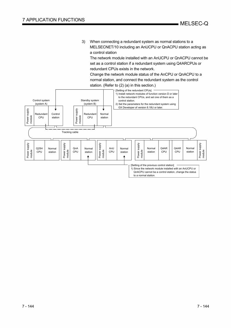
7 - 144 7 - 144
MELSEC-Q 7 APPLICATION FUNCTIONS
3) When connecting a redundant system as normal stations to a MELSECNET/10 including an AnUCPU or QnACPU station acting as
a control station
The network module installed with an AnUCPU or QnACPU cannot be set as a control station if a redundant system using Q4ARCPUs or
redundant CPUs exists in the network.
Change the network module status of the AnCPU or QnACPU to a normal station, and connect the redundant system as the control
station. (Refer to (2) (a) in this section.)
Standby system(system B)
Normalstation
Q25HCPU
QnACPU
Control system(system A)
Po
wer
sup
ply
mo
dule
RedundantCPU
Controlstation
Tracking cable
AnUCPU
Q4ARCPU
Q4ARCPU
[Setting of the redundant CPUs]1) Install network modules of function version D or later to the redundant CPUs, and set one of them as a control station.2) Set the parameters for the redundant system using GX Developer of version 8.18U or later.
[Setting of the previous control station]1) Since the network module installed with an AnUCPU or QnACPU cannot be a control station, change the status to a normal station.
Po
wer
sup
ply
mo
dule
RedundantCPU
Pow
er s
upp
ly
mod
ule
Normalstation
Pow
er s
upp
ly
mod
ule
Normalstation
Pow
er s
upp
ly
mod
ule
Normalstation
Normalstation
Pow
er s
upp
ly
mod
ule
Pow
er s
upp
ly
mod
ule
Normalstation

7 - 145 7 - 145
MELSEC-Q 7 APPLICATION FUNCTIONS
7.10.3 Pairing setting in a redundant system
A redundant system consists of a control system and a standby system.
In pairing setting, set a combination of the station numbers of the network modules making up the redundant system.
When there is a redundant system in the network, the pairing setting must be done
with the common parameters of the control station*1. *2
*1: For the control station, use a network module of function version D or later.
*2: Make the pairing setting using GX Developer of version 8.18U or later.
(1) Setting items Make settings in "Pairing" on the "Network Range Assignment" screen with careful consideration for the following points:
1) Set numbers of two adjoining stations as a pair. The station with the smaller
station number can be set to either redundant CPU of system A or B. 2) The last station number and station No. 1 (example: station Nos. 64 and 1)
cannot be paired.
3) Confirm that the stations to be paired are installed with redundant CPUs. If either of the paired stations has a QCPU other than the redundant CPU, an
error will occur in the CPU module.
POINT
Before pairing setting, confirm the station numbers of the network modules. If the contents of pairing setting do not match the actual combination of the station
numbers of the network modules, a receive data error will occur when the power is
turned on or at the time of system switching.

7 - 146 7 - 146
MELSEC-Q 7 APPLICATION FUNCTIONS
(2) Setting example and cyclic transmission
The following system configuration example is used to describe a setting example and cyclic transmission.
Q25HCPU
Normalstation(station No. 4)
Q25HCPU
Normalstation(station No. 3)
Standby system(system B)
Control system(system A)
Pow
er s
upp
lym
odu
le
Re
dun
dan
tC
PU
Controlstation(station No. 1)
Set two adjoining stationnumbers as a pair.
Confirm that the network modules set forpairing are connected to the redundant CPUs.
Tracking cable
Pow
er s
upp
lym
odu
le
Red
unda
ntC
PU
Normalstation(station No. 2)
Pow
er s
uppl
ym
odul
e
Pow
er s
uppl
ym
odul
e
(a) Setting example
This example shows the send range for each station (LB/LW setting) when 256 points are assigned to each of station Nos. 1 to 4.
1) To pair station Nos. 1 and 2, set the smaller station number to "Enable" (station No. 1 in this case).2) By setting station No. 1 to "Enable", the send range for station No. 1 will be copied as that for station No. 2.
1)
2)

7 - 147 7 - 147
MELSEC-Q 7 APPLICATION FUNCTIONS
(b) Cyclic transmission
Station No. 4
Host stationsend range
Station No. 1 (2)Received data
Received dataStation No. 3
Host stationsend range
Station No. 3Received data
Station No. 4Received data
Station No. 3Received data
Station No. 4Received data
Station No. 3
Host stationsend range
Station No. 1 (2)Received data
Station No. 4Received data
Redundant system
2)
2)
0000H
00FFH
0100H
01FFH
0200H
02FFH
1)
1)
Host stationsend range
1) Station No. 2 takes over the host station send range data handled by station No. 1 (data tracked) and sends them to other stations without discontinuing a data link.2) Station No. 2 receives data from other stations.
[When station No. 1 is cut off due to a communication error (system switching occurs)]If a communication error occurs in station No. 1 and it is consequently cut off from the network, the network module automatically issues a system switching request to the control system CPU, and system switching occurs in the redundant system.After system switching, station No. 2, a new control system, continues a data link.Cyclic transmission after system switching in the redundant system is shown below.
Station No. 2(control system)
Station No. 1(standby system)

7 - 148 7 - 148
MELSEC-Q 7 APPLICATION FUNCTIONS
POINT
(1) Communication by LX/LY is not supported by the pairing setting. (2) Set the refresh target devices of LB/LW set in the host station send range of the
redundant system as tracking devices. For details, refer to the QnPRHCPU User's Manual (Redundant System).
(3) When tracking a link special relay and a link special register, exercise care not to transfer the link special relay (SB0020 to SB01FF) and the link special register (SW0020 to SW01FF) in use by the system.
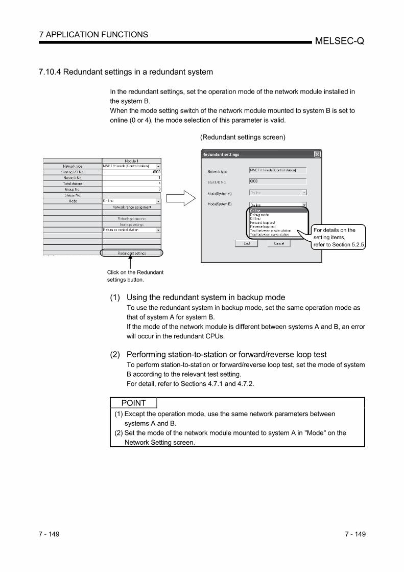
7 - 149 7 - 149
MELSEC-Q 7 APPLICATION FUNCTIONS
7.10.4 Redundant settings in a redundant system
In the redundant settings, set the operation mode of the network module installed in
the system B. When the mode setting switch of the network module mounted to system B is set to
online (0 or 4), the mode selection of this parameter is valid.
(Redundant settings screen)
For details on the setting items, refer to Section 5.2.5.
Click on the Redundantsettings button.
(1) Using the redundant system in backup mode
To use the redundant system in backup mode, set the same operation mode as that of system A for system B.
If the mode of the network module is different between systems A and B, an error
will occur in the redundant CPUs.
(2) Performing station-to-station or forward/reverse loop test To perform station-to-station or forward/reverse loop test, set the mode of system B according to the relevant test setting.
For detail, refer to Sections 4.7.1 and 4.7.2.
POINT
(1) Except the operation mode, use the same network parameters between
systems A and B. (2) Set the mode of the network module mounted to system A in "Mode" on the
Network Setting screen.
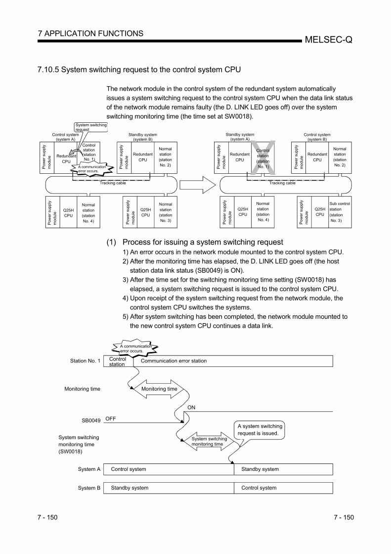
7 - 150 7 - 150
MELSEC-Q 7 APPLICATION FUNCTIONS
7.10.5 System switching request to the control system CPU
The network module in the control system of the redundant system automatically
issues a system switching request to the control system CPU when the data link status of the network module remains faulty (the D. LINK LED goes off) over the system
switching monitoring time (the time set at SW0018).
Standby system(system B)
Normalstation(stationNo. 2)
Q25HCPU
Normalstation(stationNo. 4)
Q25HCPU
Normalstation(stationNo. 3)
Control system(system A)
Po
wer
su
pply
mo
dule
Controlstation(station No. 1)
Tracking cable
A communication error occurs.
System switchingrequest
Control system(system B)
Q25HCPU
Normalstation(station No. 4)
Q25HCPU
Standby system(system A)
Controlstation(station No. 1)
RedundantCPU
Po
wer
su
pply
mo
dule
Redundant
CPU
Pow
er s
uppl
ym
odul
e
Po
wer
sup
ply
mo
dule
Po
wer
su
pply
mo
dule
Po
wer
sup
ply
mo
dule
Redundant
CPU
Tracking cable
Pow
er
sup
ply
mo
dule
Po
wer
sup
ply
mo
dule
Redundant
CPU
Normalstation(stationNo. 2)
Sub controlstation
(station No. 3)
(1) Process for issuing a system switching request 1) An error occurs in the network module mounted to the control system CPU.
2) After the monitoring time has elapsed, the D. LINK LED goes off (the host station data link status (SB0049) is ON).
3) After the time set for the switching monitoring time setting (SW0018) has
elapsed, a system switching request is issued to the control system CPU. 4) Upon receipt of the system switching request from the network module, the
control system CPU switches the systems.
5) After system switching has been completed, the network module mounted to the new control system CPU continues a data link.
Controlstation
Station No. 1 Communication error station
System A Control system Standby system
Monitoring timeMonitoring time
SB0049 OFF
ON
System switchingmonitoring time
System switching monitoring time(SW0018)
A communication error occurs.
A system switchingrequest is issued.
System B Standby system Control system

7 - 151 7 - 151
MELSEC-Q 7 APPLICATION FUNCTIONS
(2) System switching monitoring time
Set the time between an error occurring in the own station data link status (The D.
LINK LED turns off.) and a system switching request issued using SW0018
(System switching monitoring time setting). For details of SB and SW, refer to Appendices 3 and 4.
Set value Monitoring time before issuing a system switching request
0 (default) A system switching request is issued 2 seconds after SB0049 turns
on.
1 to 500*1 A system switching request is issued (set value x 10 ms) after
SB0049 turns on.
*1: This set value is valid when the system switching monitoring time setting valid flag
(SB0018) is on. To reduce the system switching monitoring time from 2 seconds (default) to 0.5 seconds, set SB0018 and SW0018 in the sequence program as shown below.
System switching monitoringtime setting invalid instructed
System switching monitoringtime setting valid instructed Sets 0.5 seconds for system switching
monitoring time.
Makes SW0018 setting valid.
Makes SW0018 setting invalid.
POINT
The network module issues a system switching request through the process
described in (1) of this section and automatically switches the systems of the redundant system.
However, if the standby station has been already in an error status (power supply
off, redundant CPU resetting, stop error, etc.), the system will not be switched even if the network module issues a system switching request to the control system
CPU.
For details, refer to the QnPRHCPU User's Manual (Redundant System).

7 - 152 7 - 152
MELSEC-Q 7 APPLICATION FUNCTIONS
7.10.6 Function for returning to control station in a redundant system
This section describes unavailability of the function for returning to control station
status when a redundant system has been acting as a control station. In the redundant system, when the redundant CPU is in the standby system at the time
of return to the system, the previous control station is returned as a normal station
even if "Return as control station" is set for the return setting for the station.
Standby system
Control system(system B)
Normalstation(station No. 2)
Q25HCPU
Normalstation(stationNo. 4)
Q25HCPU
Normalstation
Sub controlstation(stationNo. 3)
Control system
Standby system(system A)
Po
wer
sup
ply
mod
ule Redundant
CPU
1) When the control station falls into a communication error, another normal station will become a sub control station.
Controlstation(stationNo. 1)
Control system(system B)
Q25HCPU
Q25HCPU
Sub controlstation (station No. 3)
Standby system(system A)
2) System switching does not occur even if station No. 1 returns to the system, and system A remains as the standby system and returns as a normal station (it does not return as a control station).
A communicationerror occurs.
Pow
er s
uppl
ym
odul
e
RedundantCPU
Pow
er s
uppl
ym
odul
e
RedundantCPU
Normalstation(stationNo. 1)
Pow
er s
uppl
ym
odul
e
RedundantCPU
Normalstation(stationNo. 2)
Pow
er s
uppl
ym
odul
e
Pow
er s
uppl
ym
odul
e
Pow
er s
uppl
ym
odul
e
Pow
er s
uppl
ym
odul
e
Normalstation(stationNo. 4)

7 - 153 7 - 153
MELSEC-Q 7 APPLICATION FUNCTIONS
7.10.7 Data retention time for system switching
This section describes the cyclic data retention time at another station when system
switching occurs in the redundant system. Calculate the cyclic data retention time at another station based on:
• Monitoring time (Refer to Section 5.4);
• System switching monitoring time (Refer to Section 7.10.5); • Control station shift time (Refer to Section 3.3.5);
• Redundant CPU system switching time (refer to the QnPRHCPU User's Manual
(Redundant System); and • Redundant CPU scan time (refer to the QnPRHCPU User's Manual (Redundant
System).
The expression of the cyclic data retention time at another station depends on the reason(s) for system switching.
Reason Expression
Control system power supply module malfunction, power
supply off Refer to (1) of this section.
Control system CPU malfunction, resetting
Control system CPU stop error
Refer to (2) of this section. Execution of system switching instruction
System switching operation from GX Developer
System switching request from other network module
System switching request from network module (host station) Refer to (3) of this section.
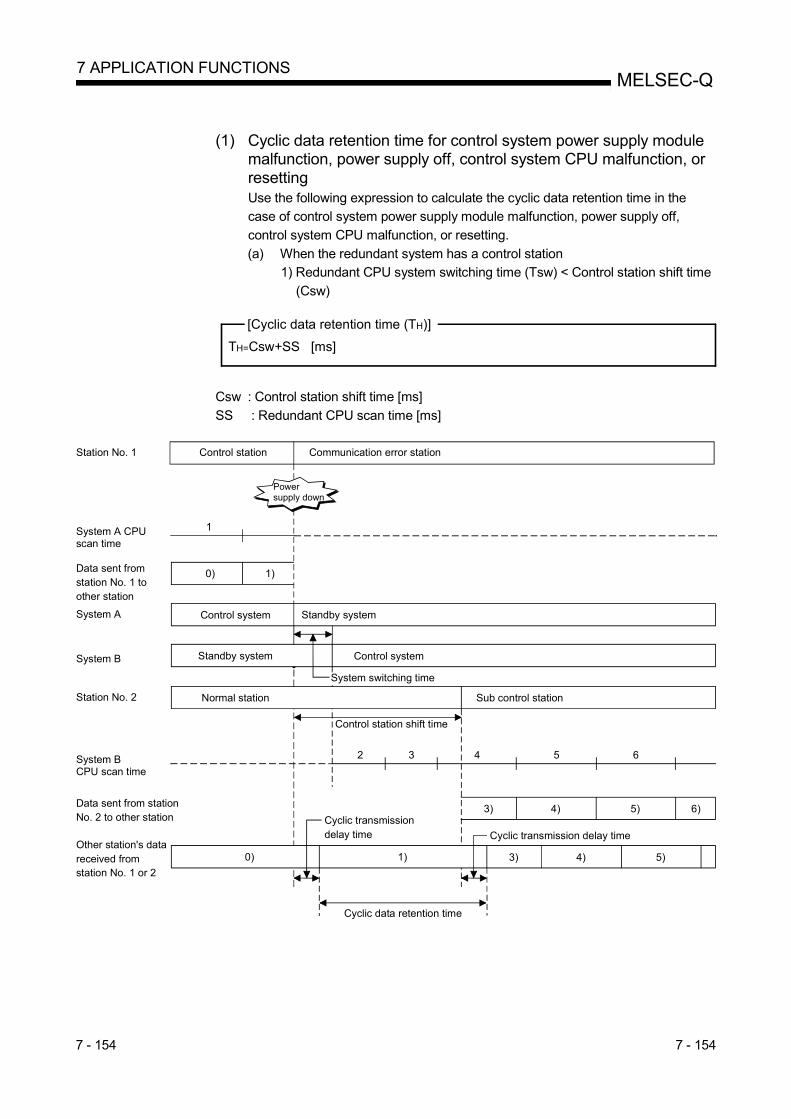
7 - 154 7 - 154
MELSEC-Q 7 APPLICATION FUNCTIONS
(1) Cyclic data retention time for control system power supply module
malfunction, power supply off, control system CPU malfunction, or resetting Use the following expression to calculate the cyclic data retention time in the case of control system power supply module malfunction, power supply off,
control system CPU malfunction, or resetting.
(a) When the redundant system has a control station 1) Redundant CPU system switching time (Tsw) < Control station shift time
(Csw)
[Cyclic data retention time (TH)]
TH=Csw+SS [ms]
Csw : Control station shift time [ms]
SS : Redundant CPU scan time [ms]
Control stationStation No. 1 Communication error station
System A Control system
System B Standby system
System A CPUscan time
1
Station No. 2 Normal station Sub control station
Data sent fromstation No. 1 toother station
Control system
Standby system
1)
Control station shift time
System B CPU scan time
2 3 4 5 6
Data sent from stationNo. 2 to other station
3) 5) 6)4)
Other station's datareceived fromstation No. 1 or 2
1) 3) 5)4)
Powersupply down
Cyclic data retention time
Cyclic transmissiondelay time Cyclic transmission delay time
System switching time
0)
0)

7 - 155 7 - 155
MELSEC-Q 7 APPLICATION FUNCTIONS
2) Redundant CPU system switching time (Tsw) > Control station shift time (Csw)
[Cyclic data retention time (TH)]
TH = Tsw + SS [ms]
Tsw : Redundant CPU system switching time [ms] SS : Redundant CPU scan time [ms]
Control stationStation No. 1 Communication error station
System A Control system
System B Standby system
System A CPUscan time
1
Station No. 2 Normal station Sub control station
Data sent from stationNo. 1 to other station
Control system
Standby system
1)
Control station shift time
System B CPU scan time
2 3 4 5
Data sent from stationNo. 2 to other station
Other station's datareceived from station No. 1 or 2
1)
Power supplydown
Cyclic data retention time
System switching time
1) 2) 3) 4)
Cyclic transmission delay time
2) 3) 4)
Cyclic transmission delay time
0)
0)

7 - 156 7 - 156
MELSEC-Q 7 APPLICATION FUNCTIONS
(b) When the redundant system has normal stations
[Cyclic data retention time (TH)]
TH = Tsw + SS [ms]
Tsw : Redundant CPU system switching time [ms]
SS : Redundant CPU scan time [ms]
Normal stationStation No. 1 Communication error station
System A Control system
System B Standby system
System ACPU scan time
1
Data sent fromstation No. 1 toother station
Control system
Standby system
1)
System switching time
System BCPU scan time
2 3 4 5
Data sent fromstation No. 2 toother station
Other station's data receivedfrom stationNo. 1 or 2
1)
Cyclic data retention time
1) 2) 3) 4)
Cyclic transmission delay time
2) 3) 4)
Cyclic transmission delay time
0)
0)
Power supplydown

7 - 157 7 - 157
MELSEC-Q 7 APPLICATION FUNCTIONS
(2) Cyclic data retention time for a control system CPU stop error,
execution of a system switching instruction, system switching operation from GX Developer, or system switching requesting from other network module Use the following expression to calculate the cyclic data retention time in the
case of a control system CPU stop error, execution of a system switching
instruction, system switching operation from GX Developer, and system switching requesting from other network module.
[Cyclic data retention time (TH)]
TH = Tsw + SS [ms]
Tsw : Redundant CPU system switching time [ms] SS : Redundant CPU scan time [ms]
System A Control system
System B Standby system
System Ascan time
1
Data sent fromstation No. 1 toother station
Control system
Standby system
1)0)
System Bscan time
3 4 5
Data sent from station No. 2 to other station
2) 4)3)
Other station's data receivedfrom station No. 1 or 2
1)0)
Cyclic data retention time
Cyclic transmissiondelay time
System switching time
Execution of systemswitching instruction
2
Cyclic transmissiondelay time
2) 4)3)

7 - 158 7 - 158
MELSEC-Q 7 APPLICATION FUNCTIONS
(3) Cyclic data retention time for system switching requesting from a
network module (host station) Use the following expression to calculate the cyclic data retention time in the
case of system switching requesting from a network module (host station).
K : Monitoring time [ms] Tc : System switching monitoring time [ms]
Tsw : Redundant CPU system switching time [ms]
SS : Redundant CPU scan time [ms]
Other station's data receivedfrom stationNo. 1 or 2
Control stationStation No. 1 Communication error station
System A Control system Standby system
Monitoring time
SB0049 OFF
ON
A communication error occurs.
A system switchingrequest is issued.
System B Standby system Control system
System ACPU scan time
System switchingmonitoring time
System switching time
1 2 3 4
Data sent from station No. 2to other station
5)
Cyclic data retention time
5 6
1)
Cyclic transmission delay timeCyclic transmission delay time
System BCPU scan time
Data sent fromstation No. 1 toother station
1)0)
4)
5)4)0)

7 - 159 7 - 159
MELSEC-Q 7 APPLICATION FUNCTIONS
7.10.8 Routing via a redundant system
This section describes the function of routing via a redundant system. (1) Routing via a redundant system
To use the routing via a redundant system, set the network module mounted to the control system CPU as a station to be routed.
Standby system (system B)
Q25HCPU
StationNo. 3
Po
wer
su
pply
m
od
ule
Q25HCPU
StationNo. 3
Control system (system A)
Network parameter settings
Destinationnetwork No.
Relaynetwork No.
Relay station No.
1 2 1
Network No. 2
Network No. 1
Pow
er
sup
ply
mod
ule
RedundantCPU
StationNo. 1
StationNo. 1
Pow
er
sup
ply
mod
ule
RedundantCPU
StationNo. 2
StationNo. 2
Pow
er
sup
ply
mod
ule
When the control system is switched, the routing parameter must be changed to go through the station of the new control system. Change the routing parameter with the RTWRITE instruction. For a sample program in the following system configuration example, refer to (2) of this section.
Control system (system B)
Po
wer
su
pply
mo
dul
e
RedundantCPU
StationNo. 2
StationNo. 2
Po
we
r su
ppl
ym
odu
le
Q25HCPU
StationNo. 3
Pow
er
sup
ply
mod
ule
Q25HCPU
StationNo. 3
Standby system (system A)
Po
wer
su
pply
mo
dul
e
RedundantCPU
StationNo. 1
StationNo. 1
Network parameter settingsDestinationnetwork No.
Relaynetwork No.
Relaystation No.
1 2 1 2
Change this parameterwith the RTWRITEinstruction.
Network No. 2
Network No. 1
A communicationerror occurs.

7 - 160 7 - 160
MELSEC-Q 7 APPLICATION FUNCTIONS
(2) RTWRITE instruction
The following is a sample program for changing the routing parameters for the
requesting station (network No. 2, station No. 3) shown in (1) of this section using
the RTWRITE instruction. For details of the RTWRITE instruction, refer to the MELSEC-Q/L Programming
Manual (Common Instruction).
Relay network No. 2
Relay station No. 2
Dummy is set.
Destination network No. 1
Relay network No. 2
Relay station No. 1
Dummy is set.
Destination network No. 1
Relaying via network No. 2, station No. 2
Relaying via network No. 2, station No. 1

8 - 1 8 - 1
MELSEC-Q 8 TROUBLESHOOTING
8 TROUBLESHOOTING In order to improve the reliability of the system, it is important to fix errors immediately and in the correct way. For that purpose, it is necessary to grasp the contents of any errors quickly and accurately. Errors can be checked in three ways as explained below: (1) Network diagnostics with GX Developer
(a) Network monitor (Refer to Section 8.1) The status of the following four types of networks can be checked by monitoring the line: 1) Status of the entire network: Host information 2) Data link status and parameter status, etc. of each station:
Other station information 3) Control station information, detailed data link information, etc.:
Network monitor details 4) Loop switch count, line error, communication error, etc.:
Error history monitor (b) Diagnostic tests (Refer to Sections 4.8 and 7.8)
The following five items can be checked or executed through the diagnostic tests: 1) Wiring status (IN/OUT, etc.) of the data link cable:
Loop test (required for optical loop) 2) Setting status of numbers: control station/remote master station
duplication, network numbers and group numbers: Setup confirmation test
3) The order of stations connected in the direction of the forward loop and the reverse loop: Station order check test
4) Setting status of the routing parameters: Communication test 5) Link startup/stop for the host, specified stations and all stations:
Network test (2) Confirmation by error code: Refer to Section 8.3
When either cyclic transmission or transient transmission using dedicated link instructions or GX Developer (communication with other stations) was not normally performed, an error code is stored in the link special register and the system monitor. The contents of the error can be checked by this error code.
(3) Confirmation by the LED displays on the front of the network module (Refer to Section 4.2) With the LED displays, the following errors can be checked: whether the host is operating or stopped, whether the station acts as a control station or a normal station, whether the baton pass is being executed, whether data linking is being executed, whether data is being transmitted/received, and whether any error has occurred.
(4) Confirmation of the error history of the entire system (Refer to Section 8.3) By using GX Works 2, error history of the entire system can be checked even after errors were cleared by powering on and then off the programmable controller or by resetting the programmable controller CPU.
REMARKS In order to fix the errors that may have occurred during data linking quickly and efficiently, it is important to perform offline tests of the network module and check the data link cable when starting up the system. Make sure to perform the following checks, which are explained in Chapter 4, "Setup and Procedures Before Starting the Operation." 1) Standalone operation check and operational setting of the network module 2) Offline tests:
Hardware test, Internal self-loopback test, self-loopback test, station-to-station test, and forward loop/reverse loop test (required for optical loop)
3) Check the connection of the data link cable.
8

8 - 2 8 - 2
MELSEC-Q 8 TROUBLESHOOTING
8.1 Network Diagnostics (Network Monitor)
The status of the MELSECNET/H can be checked using the network diagnostic
function of GX Developer.
When an error occurs, the faulty station can be identified using the host information,
other station information, and error history monitor functions of the network.
The following lists the items that can be checked with the network diagnostic function.
8

8 - 3 8 - 3
MELSEC-Q 8 TROUBLESHOOTING
…………………………Section 4.8.3
Error history details
Error history monitor
Network test
……………………………Section 4.8.4
…………………………………Section 4.8.1
…………………………Section 7.8
…………………………Section 4.8.2
From previous page [Status of self station] • Parameter setting • Reserved station setting • Transmission mode • Duplex transmission setting • Duplex transmission status
[Clear type] Clearing number of retries, etc,
[Network information] • Network type • Module No. • Network No. • Group No. • Station No.[Loop switching] Number of occurrences[Transient transmission] Number of occurrences[Forward loop] • Retry • Line trouble • Communication errors (UNDER, CRC, OVER, etc.)[Reverse loop] • Retry
• Line trouble • Communication errors (UNDER, CRC, OVER, etc.)
[Network information] • Network type • Module No. • Network No. • Group No. • Station No.[Loop switching] Station number, cause, status after switch[Transient transmission errors] Error code, error type
Clear error history
Station order check test
Setup confirmation test
Loop test
Communication test

8 - 4 8 - 4
MELSEC-Q 8 TROUBLESHOOTING
POINT (1) The target of the network diagnostics is the host's network specified as the
connection destination. (2) When another station is specified in the transfer setup, only the host
information and other stations' information are available in the network diagnostics.
(3) The network diagnostics cannot be displayed correctly while the network module is executing the offline test.
(4) When the link dedicated instruction is used to access the other station programmable controller during network diagnosis, the execution of the link dedicated instruction may be delayed. After taking the following measures, perform network diagnosis processing and execute the link dedicated instruction. • Execute the COM instruction. • Secure the communication processing security time for 2 to 3ms.
For the High Performance model QCPU, Process CPU, and Redundant CPU, set it by the special register SD315. For the Universal model QCPU, set it by the service processing setting of the PLC parameter (PLC system) of GX Developer.
REMARKS
SB and SW found in the explanations of each item indicate the link special relay (SB) or the link special register (SW) used for monitoring.

8 - 5 8 - 5
MELSEC-Q 8 TROUBLESHOOTING
8.1.1 Host information
On the host information screen, the information of the entire network of the connection
destination and the status of the host can be checked.
2)
3)
4)
1)
5)6)
7)
9)
8)
[Network info.]
1) Network type (SB0040, SB0044, SB0057, SB005A, SW0044, SW0046)
Displays the network type of the host
• MELSECNET/H (loop) PLC to PLC network control station
• MELSECNET/H (loop) PLC to PLC network normal station
• MELSECNET/H Extended Mode (loop) PLC to PLC network control station
• MELSECNET/H Extended Mode (loop) PLC to PLC network normal
station
• MELSECNET/H (bus) PLC to PLC network control station
• MELSECNET/H (bus) PLC to PLC network normal station
• MELSECNET/H Extended Mode (bus) PLC to PLC network control station
• MELSECNET/H Extended Mode (bus) PLC to PLC network normal station
• MELSECNET/10 (loop) PLC to PLC network control station
• MELSECNET/10 (loop) PLC to PLC network normal station
• MELSECNET/10 (bus) PLC to PLC network control station
• MELSECNET/10 (bus) PLC to PLC network normal station 2) Network No. (SW0040)
Displays the network No. of the host 3) Group No. (SW0041)
Displays the group No. of the host 4) Station No. (SW0042)
Displays the station No. of the host

8 - 6 8 - 6
MELSEC-Q 8 TROUBLESHOOTING
[Link information]
5) Mode (SW0043)
Displays the operation mode of the host.
• Online
• Offline (debug mode)
• Offline
• Forward loop test
• Reverse loop test
• Station-to-station test (Station that executes tests)
• Station-to-station test (Station to be tested) 6) F loop status (SB0091), Loopback station (SB0099)
Displays the status of the forward loop side.
• Loop status : Normal/abnormal
• Loopback : Unused/"executed station number"
"---" is displayed in case of bus type. 7) R loop status (SB0095), Loopback station (SB009A)
Displays the status of the reverse loop side.
• Loop status : Normal/abnormal
• Loopback : Unused/"executed station number"
"---" is displayed in case of bus type. 8) Link scan time (SW006B/SW006C/SW006D)
Displays the maximum/minimum/current value of the link scan time of the
host. Station type
Constant link scan Control station Normal station
No
Measured value
(Displays the maximum/minimum/current value the link scan
actually took.)
Yes
Measured value
(Displays the maximum, minimum, and
current values of the times that were
actually taken. If the set value is small, the
formula in Appendix 4 (SW006B to
6D) is applied.)
Constant link
scan 2 ms
[Communication information]
9) Communication status (SB0047)
Displays the communication status of the host.
• Data link being executed (SB0047: Off)
• Data link stopped (SB0047: On)

8 - 7 8 - 7
MELSEC-Q 8 TROUBLESHOOTING
8.1.2 Other station information
On the other station information screen, information such as the communication, data link, parameter, CPU, loop and reserved station statuses of each station can be checked.
1)
2)
3)
4)
5)
6)
7)
8)
9)
10)
11)
12)
[Network info.]
This area displays the same information as the host information in Section 8.1.1.
[Other station info.] When any STOP-status station, reserved station and/or externally-powered station is detected for 1) to 8) and 12), the following mark(s) is displayed in the error information area. (For 9) to 11), "ERR" is not displayed.)
Status Display
When a faulty or STOP-status station is detected ERR
When a reserved station exists RSV
When power is supplied to a module with external power supply PWR
By clicking each item button, the corresponding status of each station is displayed. This information is displayed for the number of stations that equals to the "total number of link stations" set with the network parameters. 1) Communication status of each station (SW0070 to 73)
Displays the status of the baton pass (whether or not the transient transmission is possible). • Normal display : Communication normal station or reserved station • Highlighted display : Communication error station (disconnected status)

8 - 8 8 - 8
MELSEC-Q 8 TROUBLESHOOTING
2) Data-Link status of each station (SW0074 to 77)
Displays the status of the cyclic transmission. • Normal display : Normal station or reserved station • Highlighted display : Error station (data link not executed)
3) Parameter status of each station
Displays the parameter communication status of each station (SW0078 to 7B). • Normal display : Other than during parameter communication,
reserved station or unconnected station • Highlighted display : During parameter communication Displays the abnormal parameter status of each station (SW007C to 7F). • Normal display : Normal parameter, reserved station or unconnected
station • Highlighted display : Abnormal parameter
4) CPU operation status of each station (SW0080 to 83, SW0088 to 8B)
Displays the operation status of the CPU. When the communication status of each station is normal, the display is effective. • Normal display : CPU normal, reserved station or unconnected
station • Highlighted display : CPU error, Minor: Minor error
Serious: Medium (such as watchdog timer error) fatal (hardware error, etc.)
5) CPU RUN status of each station (SW0084 to 87)
Displays the RUN/STOP status of the CPU. When the communication status of each station is normal, the display is effective. • RUN : RUN or STEP RUN • STOP : STOP, PAUSE, ERROR or unconnected station
"---" is displayed for a reserved station.
6) Loop status of each station (SW0091 to 94, SW0095 to 98) Displays the status of the forward/reverse loops in case of the optical loop system. • Normal display : Normal, reserved station or unconnected station • Highlighted display : Error
7) Reserved station designation of each station (SW0064 to 67)
Displays the setting status of a reserved station. • Normal display : Unreserved station • Highlighted display : Reserved station
8) PSU operation status of each station extension (SW008C to 8F)
Displays the supply status of the external power 24 V DC of the network module. When the communication status of each station is normal, the display is effective. • Normal display : Not powered by 24 V DC or network module without
supply terminal • Highlighted display : 24 V DC powered

8 - 9 8 - 9
MELSEC-Q 8 TROUBLESHOOTING
9) Each station PLC operation mode status (SW01F4 to 1F7)
Displays the operation mode of the Redundant CPU.
"---" indicates that the CPU is other than the Redundant CPU. • Backup mode : Operating in the backup mode • Separate mode : Operating in the separate mode
10) Each station pairing status (SW01F8 to 1FB)
Displays the status of the pairing setting.
• No pair : Station not specified for pairing
• Pair : Station specified for pairing

8 - 10 8 - 10
MELSEC-Q 8 TROUBLESHOOTING
11) Each station PLC system status (SW01FC to 1FF)
Displays the system status of the Redundant CPU.
"---" indicates that the CPU is other than the Redundant CPU.
• Control system : Operating as the control system
• Standby system : Operating as the standby system
12) Each station network type status (SW01E0 to 1E3F)
Displays whether the network type set to the control station is consistent with
those set to the normal stations.
Reserved stations and faulty stations are displayed normally.
• When the control station is in MELSECNET/H Extended mode
Normal stations in MELSECNET/H or MELSECNET/10 mode are
displayed highlighted.
• When the control station is in MELSECNET/H or MELSECNET/10 mode
Normal stations in MELSECNET/H Extended mode are displayed
highlighted.

8 - 11 8 - 11
MELSEC-Q 8 TROUBLESHOOTING
8.1.3 Network monitor details
On the Network Monitor Details screen, the control station information, data link
information and the parameter status of the host can be checked.
2)
6)
8)
9)
11)
1)
4)
3)
5)
7)
10)
12)
13)14)
15)
16)
17)
[Network info.]
This area displays the same information as the host information in Section 8.1.1.
[Control Station Information]
1) Assign Control Station (SW0057)
Displays the number of the control station specified with the parameter. 2) Present Control Station (SW0056)
Displays the number of the station that actually controls the network. 3) Transmission Information (SB0056)
Displays the type of the station that controls the network.
When the control station goes down, the display automatically changes to
the sub-control station.
• Control station communication/sub-control station communication 4) Sub Control Station Transmission (SB0058)
Displays whether or not to execute data linking by the sub-control station
when the control station is down.
• Yes/No 5) Remote I/O Master Station Number
Displays the number of the I/O master station of X/Y communication blocks 1
and 2.
Block 1
Block 2
"None" is displayed for blocks that are not set. 6) LX/LY Allocations
Nothing is displayed

8 - 12 8 - 12
MELSEC-Q 8 TROUBLESHOOTING
[Data Link Information]
7) Total Number of Linked Stations (SW0059)
Displays the total number of link stations set with the parameter. 8) Station of Maximum Normal Transmission (SW005A)
Displays the highest station number that is executing the baton pass
normally (the status where the transient transmission is possible).
The T.PASS LED of the network module turns on for stations executing the
baton pass normally. 9) Station of Maximum Data Link (SW005B)
Displays the highest station number that is executing data linking normally
(cyclic transmission and transient transmission).
The D.LINK LED of the network module turns on for stations executing data
linking normally. 10) Transmission Status (SW0047)
Displays the communication status of the host. Indication Description
In Data Link Data link is being executed.
Suspend Data link (Other) Other station stopped the cyclic transmission.
Suspend Data link (Host) The host station stopped the cyclic
transmission.
Baton Pass (No area) No area is assigned for the host's B/W
transmission.
Baton Pass (Parameter Halt) An error is identified in the host's parameters.
Baton Pass (No Receive) The common parameters have not been
received.
Disconnecting (No Baton) Station numbers are duplicated or the cable is
not connected.
Disconnecting (Link Error) The cable is not connected.
In Test The online/offline test is being executed.
Resetting Hardware fault
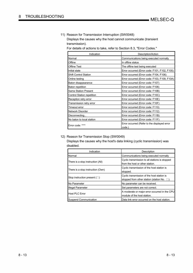
8 - 13 8 - 13
MELSEC-Q 8 TROUBLESHOOTING
11) Reason for Transmission Interruption (SW0048)
Displays the causes why the host cannot communicate (transient
transmission).
For details of actions to take, refer to Section 8.3, "Error Codes." Indication Description/Action
Normal Communications being executed normally
Offline In offline status
Offline Test The offline test being executed
Initial state Error occurred (Error code: F101, F102, F105)
Shift Control Station Error occurred (Error code: F104, F106)
Online testing Error occurred (Error code: F103, F109, F10A)
Baton disappearance Error occurred (Error code: F107)
Baton repetition Error occurred (Error code: F108)
Same Station Present Error occurred (Error code: F10B)
Control Station repetition Error occurred (Error code: F10C)
Reception retry error Error occurred (Error code: F10E)
Transmission retry error Error occurred (Error code: F10F)
Timeout error Error occurred (Error code: F110)
Network Disorder Error occurred (Error code: F112)
Disconnecting... Error occurred (Error code: F11B)
No baton to local station Error occurred (Error code: F11F)
Error code: **** Error occurred (Refer to the displayed error
code.)
12) Reason for Transmission Stop (SW0049)
Displays the causes why the host's data linking (cyclic transmission) was
disabled. Indication Description
Normal Communications being executed normally
There is a stop instruction (All) Cyclic transmission to all stations is stopped
from the host or other station.
There is a stop instruction (Own) Cyclic transmission of the host station is
stopped.
Stop instruction present ( ) Cyclic transmission of the host station is
stopped from other station (station No. ).
No Parameter No parameter can be received.
Illegal Parameter Set parameters are not correct.
Host PLC Error A moderate or major error occurred in the CPU
module of the host station.
Suspend Communication Data link error occurred on the host station.

8 - 14 8 - 14
MELSEC-Q 8 TROUBLESHOOTING
[Status of Self Station]
13) Parameter Setting (SB0054, SW0054)
Displays the parameter setting status of the host.
• Common parameters
• Common + specific
• Default parameters
• Default + specific 14) Reserved Station Setting (SB0064)
Displays the designation status of reserved stations.
• Yes/No 15) Transmission Mode (SB0068)
Displays the link scan status.
• Normal mode
• Constant link scan 16) Duplex Transmission Setting (SB0069)
Displays the designation status of the multiplex transmission.
• Normal transmission
• Multiplex transmission
"----" is displayed for the bus type system. 17) Duplex Transmission Status (SB006A)
Displays the status of the multiplex transmission.
• Normal transmission
• Multiplex transmission
"----" is displayed for the bus type system.
REMARKS
(1) A station that detected a forward loop error executes the reverse loopback.
(2) A station that detected a reverse loop error executes the forward loopback.
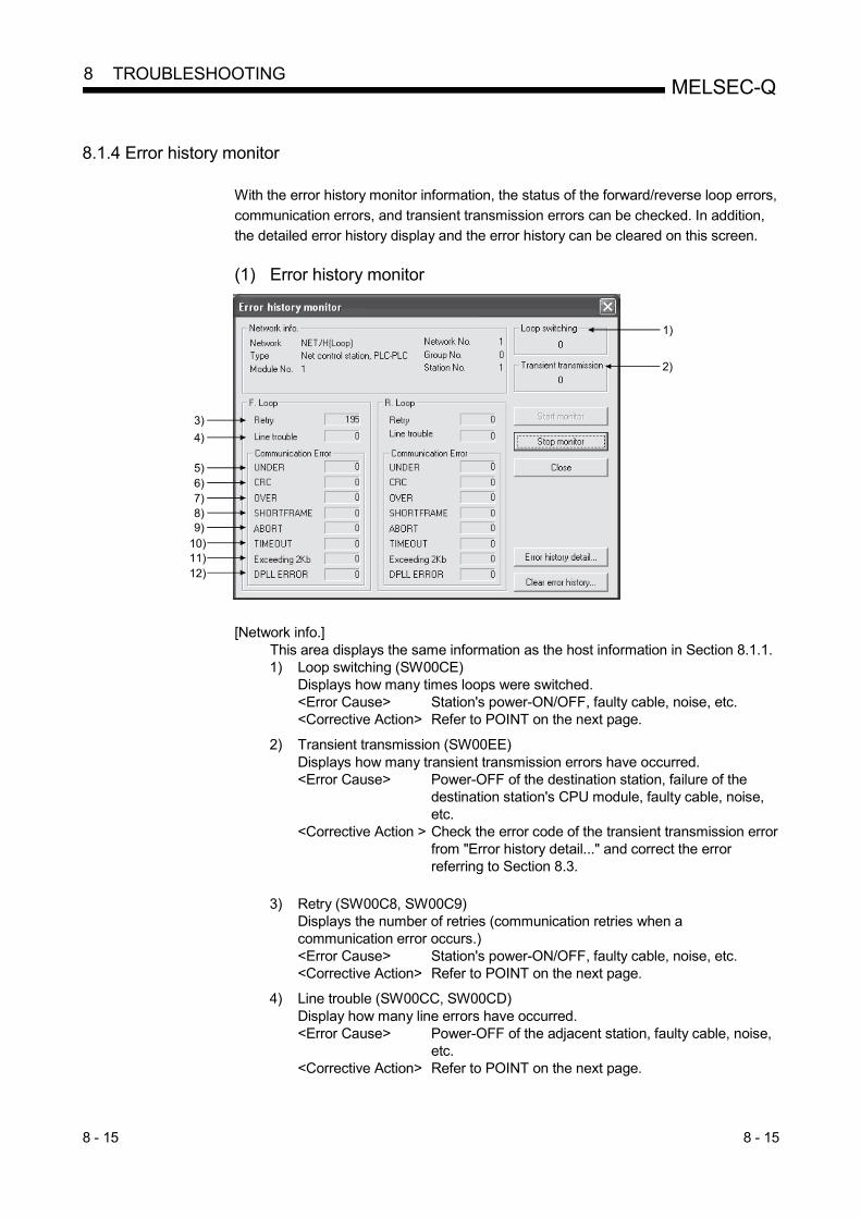
8 - 15 8 - 15
MELSEC-Q 8 TROUBLESHOOTING
8.1.4 Error history monitor
With the error history monitor information, the status of the forward/reverse loop errors,
communication errors, and transient transmission errors can be checked. In addition,
the detailed error history display and the error history can be cleared on this screen.
(1) Error history monitor
3)
4)
5)6)7)8)9)
10)11)12)
1)
2)
[Network info.] This area displays the same information as the host information in Section 8.1.1. 1) Loop switching (SW00CE)
Displays how many times loops were switched. <Error Cause> Station's power-ON/OFF, faulty cable, noise, etc. <Corrective Action> Refer to POINT on the next page.
2) Transient transmission (SW00EE) Displays how many transient transmission errors have occurred. <Error Cause> Power-OFF of the destination station, failure of the
destination station's CPU module, faulty cable, noise, etc.
<Corrective Action > Check the error code of the transient transmission error from "Error history detail..." and correct the error referring to Section 8.3.
3) Retry (SW00C8, SW00C9) Displays the number of retries (communication retries when a communication error occurs.) <Error Cause> Station's power-ON/OFF, faulty cable, noise, etc. <Corrective Action> Refer to POINT on the next page.
4) Line trouble (SW00CC, SW00CD) Display how many line errors have occurred. <Error Cause> Power-OFF of the adjacent station, faulty cable, noise,
etc. <Corrective Action> Refer to POINT on the next page.

8 - 16 8 - 16
MELSEC-Q 8 TROUBLESHOOTING
5) UNDER (SW00B8, SW00C0) Displays how many UNDER errors have occurred. <Error Cause> Power-ON/OFF of the adjacent station, faulty cable, etc. <Corrective Action> Refer to the following POINT.
6) CRC (SW00B9, SW00C1) Displays how many CRC errors have occurred. <Error Cause> Isolation of the sending station, faulty cable, hardware
failure, noise, etc. <Corrective Action> Refer to the following POINT.
7) OVER (SW00BA, SW00C2) Displays how many OVER errors have occurred. <Error Cause> Faulty cable, hardware failure, noise, etc. <Corrective Action> Refer to the following POINT.
8) SHORTFRAME (SW00BB, SW00C3) Displays how many short frame errors (messages too short) have occurred. <Error Cause> Faulty cable, hardware failure, noise, etc. <Corrective Action> Refer to the following POINT.
9) ABORT (SW00BC, SW00C4)
Displays how many AB and IF errors have occurred. <Error Cause> Isolation of the sending station, faulty cable, hardware
failure, noise, etc. <Corrective Action> Refer to the following POINT.
10) TIMEOUT (SW00BD, SW00C5)
Displays how many timeout errors have occurred. <Error Cause> Data link monitoring time too short, faulty cable, noise,
etc. <Corrective Action> Refer to the following POINT.
11) Exceeding 2Kb (SW00BE, SW00C6)
Display how many times messages exceeding 2k bytes were received. <Error Cause> Faulty cable, hardware failure, noise, etc. <Corrective Action> Refer to the following POINT.
12) DPLL ERROR (SW00BF, SW00C7)
Displays how many times the DPLL errors occurred. <Error Cause> Faulty cable, hardware failure, noise, etc. <Corrective Action> Refer to the following POINT.
POINT
The number of each error occurrence does not necessarily mean a problem unless
the count value rises frequently during operation. If it rises frequently, observe the
following.
1) Check the power-ON/OFF status of the host and other stations.
2) Check the condition of the cables and connectors. (Disconnection or
looseness of the connectors, cable breakage, cable length, etc.)
3) Perform the self-loopback test, internal self-loopback test and hardware test.
4) Perform the station-to-station test, forward/reverse loop test.
5) Referring to the user's manual (for hardware) of the network module, perform
the wiring again. Also, set the system again referring to the user's manual of
the CPU module.

8 - 17 8 - 17
MELSEC-Q 8 TROUBLESHOOTING
(2) Error history detail monitoring
Displays the causes of loop switches and the history of the transient transmission errors.
1)2)3)
4)
[Loop switching]
1) Station No. (SW00E0 to 00E7) Displays the number of the station (not necessarily an adjacent station) that requested the loop switch and loopback.
2) Factor (SW00D0 to 00DF)
Displays the reason why the loop switch and loop back are executed. • Normal return • Forward loop hardware error : Cable or optical module error • Reverse loop hardware error : Cable or optical module error
3) Switched to (SW00D0 to 00DF) Displays the data link status after the loop switch. • Multiplex transmission: Forward loop/reverse loop normal • Forward loop transmission • Reverse loop transmission • Loopback transmission
[Transient transmission errors]
4) Error code, error type (SW00F0 to 00FF) Displays the error code. Refer to Section 8.3
(3) Clear of error history
Error history can be cleared for each item by selecting the item from the list.

8 - 18 8 - 18
MELSEC-Q 8 TROUBLESHOOTING
8.2 Troubleshooting
Check the programmable controller CPU for an error before starting the troubleshooting of the network module and network. If the RUN LED of the programmable controller CPU is off/flickering or the ERR. LED is on, identify the error that occurred in the programmable controller CPU, and take corrective action.
(1) Check that the host has joined the network.
Start the troubleshooting of the host by monitoring the status of the host. First, check whether or not the host has joined the network. This is important because it is not possible to monitor the status of other stations and to perform troubleshooting on other stations unless the host has joined the network. The troubleshooting flowchart shown below explains the sequence from checking an error to enabling a baton pass (in order to join the network).
Correct the error according
to the content of the error
code stored in SW0048.
<Corrective action>
Test results?
NG
Replace the network module.<Cause>
Possible module watchdog
timer error
<Corrective action>
Check :
1) Verify the base installation.
2) Reset the CPU.
3) Replace the module.
4) Whether or not the host's
I/O slot is assigned to a
"Empty area."
<Cause>
The power is not being supplied.
Or, the overcurrent protection is
active.
<Corrective action>
1) Verify the power supply status.
2) Check that the total current
consumption of the module
installed on the base unit
does not exceed the rated
output current of the power
supply module used.
OK
No
E
Is the "T.PASS" LED of the
host lit?
Is the "RUN" LED lit?
Start
Is the "ERR." LED lit?
No
Yes
Is the power supplied
to the power supply module?
Yes YES
Execute offline tests.
1) Hardware test
2) Self-loopback test
3) Internal self-loopback test
EndThe host is
in the normal status.
Yes
The host's baton pass
is normal.
No
No
POINT If the T. PASS LED turns on and off and looks unstable, refer to the following. <Cause>
The line status is assumed to be unstable. <Troubleshooting>
1) Check the connector for loose connection and the cable for a break. 2) Check that the cable used conforms to the specifications. 3) Check that the overall length and station-to-station distance are within
specifications. (Refer to Section 4.6 Cable Connection.).

8 - 19 8 - 19
MELSEC-Q 8 TROUBLESHOOTING
(2) From monitoring the network status to troubleshooting of a faulty
station The following flowchart illustrates the procedure for monitoring the status of the entire network, detecting a faulty station, and then performing troubleshooting for the applicable station. The status of the entire network is monitored with GX Developer.
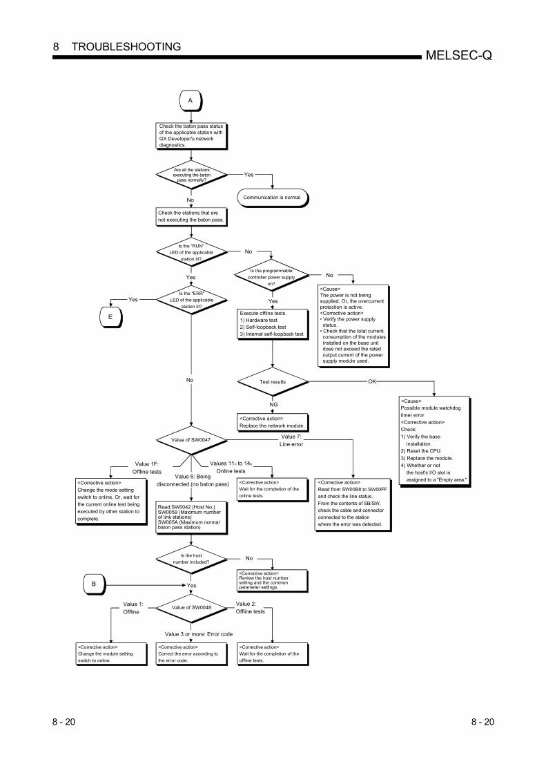
8 - 20 8 - 20
MELSEC-Q 8 TROUBLESHOOTING
Communication is normal.
Are all the stations executing the baton
pass normally?
No
Check the baton pass status of the applicable station with GX Developer's network diagnostics.
Check the stations that are not executing the baton pass.
Is the "RUN"
LED of the applicable
station lit?
Yes
Is the "ERR"
LED of the applicable
station lit?Yes
Value of SW0047
Read:SW0042 (Host No.)SW0059 (Maximum number of link stations)SW005A (Maximum normal baton pass station)
Is the host
number included?
Yes
<Corrective action>
Change the mode setting
switch to online. Or, wait for
the current online test being
executed by other station to
complete.
<Corrective action>
Wait for the completion of the
online tests.
Yes
No
Value of SW0048
Value 3 or more: Error code
<Corrective action>
Correct the error according to
the error code.
<Corrective action>
Wait for the completion of the
offline tests.
<Corrective action>
Change the module setting
switch to online.
Value 1:
Offline
Value 2:
Offline tests
<Corrective action>Review the host number setting and the common parameter settings.
No
Value 1F:
Offline tests
Values 11H to 14H
Online testsValue 6: Being
disconnected (no baton pass)
Is the programmable
controller power supply
on?
Execute offline tests.1) Hardware test2) Self-loopback test3) Internal self-loopback test
Test results
<Corrective action>
Replace the network module.
NG
<Corrective action>
Read from SW00B8 to SW00FF
and check the line status.
From the contents of SB/SW,
check the cable and connector
connected to the station
where the error was detected.
Value 7:
Line error
The power is not being supplied. Or, the overcurrentprotection is active.<Corrective action>• Verify the power supply status. • Check that the total current consumption of the modules installed on the base unit does not exceed the rated output current of the power supply module used.
<Cause>
Possible module watchdog
timer error
<Corrective action>
Check:
1) Verify the base
installation.
2) Reset the CPU.
3) Replace the module.
4) Whether or not
the host's I/O slot is
assigned to a "Empty area."
<Cause>
OK
Yes
A
B
No
No
E

8 - 21 8 - 21
MELSEC-Q 8 TROUBLESHOOTING
C
No
Value of SW0047
Value 3: No host send area
Value 4: Abnormal parameters detected
Value 5: Parameters not received
<Corrective action>Check the contents of the common parameters and station inherentparameters.
Value 0: The host
transmitting
normally
<Corrective action>Check the contents of the common parameters and station inherent parameters of the stations to which data is not sent.
Yes
Communication is normal.
Is the send and receive
data within the system specifications?
: In case of SW0047 = 3, the following two causes may be considered:
1) The link device has not been assigned; only the station number was set with the
common parameters.
2) The link device was assigned, but "Send/receive link points = 0" was
specified in the station inherent parameters setting.
Is the "RUN" LED of the applicable station
lit?
Correct the error according
to the content of the error
code stored in SW0048.
<Corrective action>
Yes
Is the power supplied to the
power source module?
Yes Yes
Execute offline tests.
1) Hardware test
2) Self-loopback test
3) Internal self-loopback test
Test results?
NG
Replace the network modulePossible module watchdog
timer error
<Corrective action>
Check:
1) Review the base installation.2) Reset the CPU.
3) Replace the module.
4) Whether or not the host's
I/O slot is assigned to a
"Empty area."
<Cause>The power is not being supplied.Or, the overcurrent protection is active. <Corrective action>1) Review the power supply status. 2) Check that the total current consumption of the modules installed on the base unit does not exceed the rated output current of the power supply module used.
<Cause>
No
No
No
D
Is the "ERR" LED of the applicable station
lit?
OK
E

8 - 22 8 - 22
MELSEC-Q 8 TROUBLESHOOTING
<Cause 1> M/S error or SW error is assumed.<Corrective action 1>
<Cause 2> Programmable controller error is assumed.<Corrective action 2> Check the programmable controller CPU error in the PLC diagnostics and restore the CPU to normal. (Refer to Section 8.2.1.)
E
1) Check for duplicate station number, duplicate control station designations or switch setting error.
2) Take corrective action according to the contents of SW0047 and the error code stored in SW0048.

8 - 23 8 - 23
MELSEC-Q 8 TROUBLESHOOTING
8.2.1 Items to be checked first
Check item Checking procedure
Monitor the communication status of each station with GX
Developer's network diagnostics.
Check the CPU module status of the faulty station, the status of the network
modules, the loop status of each station to search for the location where the
error occurred.
Is the ERR. LED of the CPU module still lit or flickering?
Read the error code using GX Developer, and take proper measures against
the error. (For details, refer to the QCPU User's Manual (Hardware Design,
Maintenance and Inspection).
Check the following when LINK PARA. ERROR occurs.
1) Check whether the starting I/O in the network setting matches the slot
where the network module is installed. (Refer to Section 5.2.1.)
2) Check for consistency in the network type and the station number of the
network module. (Refer to Section 5.1.)
3) Check if the PLC side device ranges in Refresh parameters are within the
ranges set in [PLC parameter] – [Device]. (Refer to Section 5.7.2 (2).)
If refresh parameters have not been set, set them according to the
changes made in [Device] under [PLC parameter]. (Refer to Section
5.7.2 (3).)
4) When the Redundant CPU is installed, check whether the host station is
set to be paired. (Refer to Section 7.10.3.)
5) Check whether the network type of the control station matches that of the
normal stations. (Refer to Section 5.1.)
6) When the MELSECNET/H Extended mode has been set, check whether
a compatible network module is used. (Refer to Section 2.2.)
7) When the MELSECNET/H twisted bus system is configured, check that
the MNET/10 mode is not selected as the network type and either of the
forward loop and reverse loop test is not selected as the mode.
Is the on/off status of the LEDs on the network module
normal?
Check the on/off status of the RUN, ERR, L ERR. and other LEDs and
correct the error accordingly.
(Refer to Section 4.2.)
If the T. PASS LED turns on and off and looks unstable, the line status is
assumed to be unstable. Therefore, check the following.
1) Check the connector for loose connection and the cable for a break.
2) Check that the cable used conforms to the specifications.
3) Check that the overall length and station-to-station distance the
specifications.
4) Check that cables are correctly installed.
(Refer to Section 4.6 Cable Connection.)

8 - 24 8 - 24
MELSEC-Q 8 TROUBLESHOOTING
8.2.2 Data link failure on the entire system
Check item Checking procedure
Monitor the communication status of each station with GX
Developer's network diagnostics.
Check the line condition with GX Developer's network diagnostic loop test
(only in case of optical loop test).
Check the faulty station's CPU module and network module.
Check the network module and data link cable with the self-loopback test and
station-to-station test of the offline tests.
Check whether data linking is stopped for all stations.
Are the network parameters set for the control station? Check whether the network parameters from the control station's CPU
module are set.
Are the switch settings of the control station's network
module correct? Check the station number setting switches and mode setting switch. 1
Are the switches of the network modules on all stations set
in the correct position?
Make sure that the mode setting switches of the network modules on all
stations are in the same position. 1
Is the link monitoring time set to a sufficient value? Set the link monitoring time to the maximum value and check whether or not
data linking can be performed.
Did the control station and remote master station go down? Check the on/off status of the LEDs of the network modules of the control
station and the remote master station.
Did the control switch to the sub-control station?
Check that the "continue data linking by a sub-station when the control
station goes down" setting is set to "Yes" in the communication error settings
of the control station's common parameters.
1: For the QJ71NT11B, check the station number/mode setting switch.
8.2.3 Data link failure caused by reset or power-off of each station
Check item Checking procedure
Is the cable wired properly? Check the wiring status with GX Developer's network diagnostic loop test.
(Refer to Section 4.8.1.)
Is the network cable disconnected? Check the status of each station to see whether the entire system is faulty or
a specific-station is faulty, and locate the faulty area.
Are the switches of the network modules on all stations set
in the correct position?
Make sure that the mode setting switches of the network modules on all
stations are in the same position. 1
Is the setting of the link monitoring time sufficient?
Set the link monitoring time to the maximum value and check whether or not
data linking is possible. If the L ERR. LED of a normal station is lit, check the
TIME error with the GX Developer's network diagnostics.
1: For the QJ71NT11B, check the station number/mode setting switch.
POINT
In the optical loop system, do not reset the CPU modules of adjoining stations
(adjoining stations on the wiring) at the same time.
Data link may be disabled.
In the case of initializing adjoining stations at the same time, turn off the power and
turn it on again.
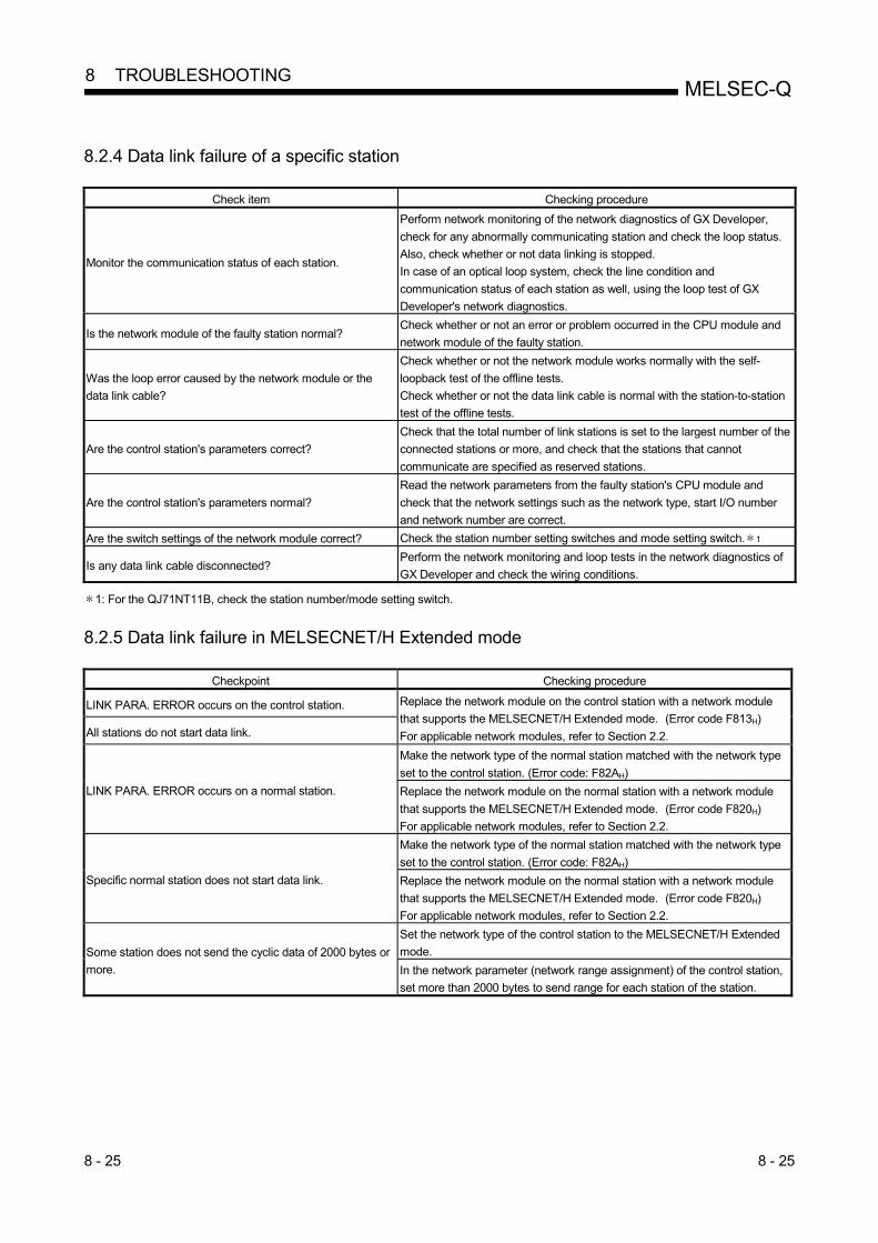
8 - 25 8 - 25
MELSEC-Q 8 TROUBLESHOOTING
8.2.4 Data link failure of a specific station
Check item Checking procedure
Monitor the communication status of each station.
Perform network monitoring of the network diagnostics of GX Developer,
check for any abnormally communicating station and check the loop status.
Also, check whether or not data linking is stopped.
In case of an optical loop system, check the line condition and
communication status of each station as well, using the loop test of GX
Developer's network diagnostics.
Is the network module of the faulty station normal? Check whether or not an error or problem occurred in the CPU module and
network module of the faulty station.
Was the loop error caused by the network module or the
data link cable?
Check whether or not the network module works normally with the self-
loopback test of the offline tests.
Check whether or not the data link cable is normal with the station-to-station
test of the offline tests.
Are the control station's parameters correct?
Check that the total number of link stations is set to the largest number of the
connected stations or more, and check that the stations that cannot
communicate are specified as reserved stations.
Are the control station's parameters normal?
Read the network parameters from the faulty station's CPU module and
check that the network settings such as the network type, start I/O number
and network number are correct.
Are the switch settings of the network module correct? Check the station number setting switches and mode setting switch. 1
Is any data link cable disconnected? Perform the network monitoring and loop tests in the network diagnostics of
GX Developer and check the wiring conditions.
1: For the QJ71NT11B, check the station number/mode setting switch.
8.2.5 Data link failure in MELSECNET/H Extended mode
Checkpoint Checking procedure
LINK PARA. ERROR occurs on the control station. Replace the network module on the control station with a network module
that supports the MELSECNET/H Extended mode. (Error code F813H)
For applicable network modules, refer to Section 2.2. All stations do not start data link.
LINK PARA. ERROR occurs on a normal station.
Make the network type of the normal station matched with the network type
set to the control station. (Error code: F82AH)
Replace the network module on the normal station with a network module
that supports the MELSECNET/H Extended mode. (Error code F820H)
For applicable network modules, refer to Section 2.2.
Specific normal station does not start data link.
Make the network type of the normal station matched with the network type
set to the control station. (Error code: F82AH)
Replace the network module on the normal station with a network module
that supports the MELSECNET/H Extended mode. (Error code F820H)
For applicable network modules, refer to Section 2.2.
Some station does not send the cyclic data of 2000 bytes or
more.
Set the network type of the control station to the MELSECNET/H Extended
mode.
In the network parameter (network range assignment) of the control station,
set more than 2000 bytes to send range for each station of the station.
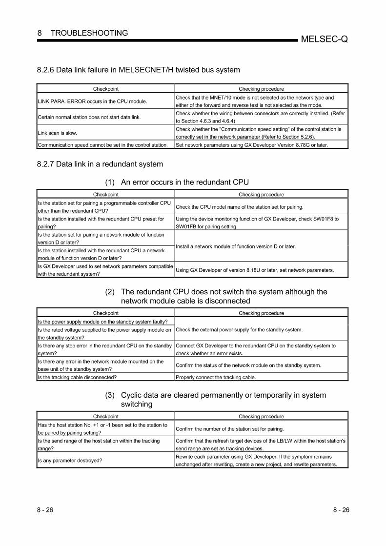
8 - 26 8 - 26
MELSEC-Q 8 TROUBLESHOOTING
8.2.6 Data link failure in MELSECNET/H twisted bus system
Checkpoint Checking procedure
LINK PARA. ERROR occurs in the CPU module. Check that the MNET/10 mode is not selected as the network type and
either of the forward and reverse test is not selected as the mode.
Certain normal station does not start data link. Check whether the wiring between connectors are correctly installed. (Refer
to Section 4.6.3 and 4.6.4)
Link scan is slow. Check whether the "Communication speed setting" of the control station is
correctly set in the network parameter (Refer to Section 5.2.6).
Communication speed cannot be set in the control station. Set network parameters using GX Developer Version 8.78G or later.
8.2.7 Data link in a redundant system
(1) An error occurs in the redundant CPU
Checkpoint Checking procedure
Is the station set for pairing a programmable controller CPU
other than the redundant CPU? Check the CPU model name of the station set for pairing.
Is the station installed with the redundant CPU preset for
pairing?
Using the device monitoring function of GX Developer, check SW01F8 to
SW01FB for pairing setting.
Is the station set for pairing a network module of function
version D or later? Install a network module of function version D or later.
Is the station installed with the redundant CPU a network
module of function version D or later?
Is GX Developer used to set network parameters compatible
with the redundant system? Using GX Developer of version 8.18U or later, set network parameters.
(2) The redundant CPU does not switch the system although the
network module cable is disconnected Checkpoint Checking procedure
Is the power supply module on the standby system faulty?
Check the external power supply for the standby system. Is the rated voltage supplied to the power supply module on
the standby system?
Is there any stop error in the redundant CPU on the standby
system?
Connect GX Developer to the redundant CPU on the standby system to
check whether an error exists.
Is there any error in the network module mounted on the
base unit of the standby system? Confirm the status of the network module on the standby system.
Is the tracking cable disconnected? Properly connect the tracking cable.
(3) Cyclic data are cleared permanently or temporarily in system
switching
Checkpoint Checking procedure
Has the host station No. +1 or -1 been set to the station to
be paired by pairing setting? Confirm the number of the station set for pairing.
Is the send range of the host station within the tracking
range?
Confirm that the refresh target devices of the LB/LW within the host station's
send range are set as tracking devices.
Is any parameter destroyed? Rewrite each parameter using GX Developer. If the symptom remains
unchanged after rewriting, create a new project, and rewrite parameters.

8 - 27 8 - 27
MELSEC-Q 8 TROUBLESHOOTING
8.2.8 Send/received data failure
(1) The cyclic transmission data is not normal
Check item Checking procedure
Is the sequence program correct?
Stop the CPU modules of both the sending and receiving stations and turn
the link device of the sending station on and off by GX Developer's test
operation to check whether or not data is sent to the receiving station.
If it is normal, review the sequence program.
If it is abnormal, review the control station's common parameters as well as
the host's refresh parameters.
Are the parameter settings of the control station and remote
master station correct? Review the range of the link devices assigned to the sending station.
Are the parameter settings of the sending station correct?
Check the settings of the refresh parameters and the station specific
parameters to see in what range of LB/LW/LX/LY of the network module the
device range used by the sequence program is stored.
Are the parameter settings of the receiving station correct?
Check the settings of the refresh parameters and the station specific
parameters to see in what device range used by the sequence program the
range of LB/LW/LX/LY of the network module received from the transmitting
station is stored.
Is the switch setting of the network module correct? Confirm that the station numbers of the network modules on system A and B
of the redundant system are n and n + 1 respectively.
Is any parameter destroyed? Rewrite each parameter using DX Developer. If the symptom remains
unchanged after rewriting, create a new project, and rewrite parameters.

8 - 28 8 - 28
MELSEC-Q 8 TROUBLESHOOTING
(2) The transient transmission is not normal
Check item Checking procedure
Did an error occur while the transient transmission was
being executed?
Check the error code at the transient transmission execution and correct the
error according to the error code table in Section 8.3.
Confirm whether a dedicated link instruction is executed to a programmable
controller CPU other than the redundant CPU with the control or standby
system specified. (Error code: 4B00H)
Check if a dedicated link instruction is executed for a CPU other than the
QCPU in the multiple CPU No. specification. (Error code: 4100H, 4B00H,
FE20H)
Confirm whether a dedicated link instruction is executed to a single CPU
system with a multiple CPU number specified. (Error code: 4B00H)
Check if a non-existing multiple CPU No. is specified in the target station
type. (Error code: 4B00H)
Are the routing parameter settings correct?
Check that the communication target is not set for a station on another
network No. If it is set for a station on another network No., correct the set
value of the routing parameter. (Refer to Section 7.4.2.)
Check the routing parameters with the communication test of GX Developer's
network diagnostics.
Is the network No. parameter correct?
Check the network No. parameter.
If the parameter is not set, the network No. has been set to 1 (default); so
check other station's network No..
A dedicated link instruction is not responded within specified
time.
Confirm whether a value out of the set range is set for the target station CPU
type.
Does the transmission go through the network module on
the standby system in the redundant system?
Using the RTWRITE instruction, change the routing parameter so that
transmission will go through the network module on the control system.
The dedicated link instruction executed in the multiple CPU
No. specification does not access the target CPU.
<When the dedicated link instruction is started from the QnACPU>
Not executable for the QnACPU.
<When the dedicated link instruction is started from the QCPU>
Check whether the QCPUs and network modules of the host station and
target station are the following versions.
QCPU: Serial number (first five digits) "06092" or later
Network module: Serial number (first five digits) "06092" or later
Check if the group or all stations has been specified for the target station
number. (Refer to Section 2.2.2 (5).)
Is the number of resends set every time the instruction is
executed?
Confirm whether a program requires the setting of the number of resends
when executing instructions.
8.2.9 Link dedicated instruction not complete
Check item Checking procedure
Is the link dedicated instruction issuing station online?
Place the link dedicated instruction issuing station online and execute the link dedicated instruction. Use SB0043 as an interlock to confirm the online status in the sequence program.

8 - 29 8 - 29
MELSEC-Q 8 TROUBLESHOOTING
8.2.10 Checking online for reverse optical fiber cable connection
This section explains the checking procedure for incorrect optical fiber cable connection (IN-IN, OUT-OUT) during online and the link special registers (SW009C to SW009F) used for the check. Unlike the loop test, the checking procedure given in this section allows a check without stopping a data link. If incorrect cable connection is found, correct the wiring after shutting off all phases of the system.
POINT Before starting the check given in this section, make sure that the following conditions are satisfied. If these are not satisfied, conduct a loop test to make a check.
Multiplex transmission function is not used. The optical fiber cables have no breaks. (Both the forward and reverse loop cables are normal.) There are no stations having data link error (power off, MELSECNET/H module failure).
(1) Checking procedure
Follow the procedure given below to check for incorrect optical fiber cable
connection (IN-IN, OUT-OUT) during online.

8 - 30 8 - 30
MELSEC-Q 8 TROUBLESHOOTING
(2) Example of checking SW009C to SW009F
An example of incorrect cable connection at Station No. 2 is shown below.
(a) Wiring diagram
QCPU QJ71LP21-25
IN OUT
QCPU QJ71LP21-25
IN OUT
QCPU QJ71LP21-25
IN OUT
QCPU QJ71LP21-25
IN OUT
Station No. 1 Station No. 2 Station No. 3 Station No. 4
Cables are connected to wrong connectorsat Station No. 2 (connected OUT-OUT with Station No. 1 and IN-IN with Station No. 3).
(b) SW009C to SW009F status Station No. SW009C to SW009F status
Station No. 1 Only Station No. 2 (bit 1) is ON or OFF.
0100
b0b1b2b3
0
b15 b4to
SW009C
0SW009D
0SW009E
0SW009F
Station No. 3
Station No. 4
Station No. 2
All stations (bit 0, bit 2, bit 3) other than Station No. 2 (bit 1) are ON or OFF.
1011
b0b1b2b3
0
b15 b4to
SW009C
0SW009D
0SW009E
0SW009F

8 - 31 8 - 31
MELSEC-Q 8 TROUBLESHOOTING
8.2.11 When different network types exist in the same network
Set all the network modules within the same network to the same network type.
If there are different network types within the same network, any of the symptoms 1) to
6) given in the following table will occur.
If any different network type is accidentally set, take corrective action with reference to
the following table.
Normal station Control station
QCPU
QnA/ AnUCPU
Serial number (first five digits) of the network module: "06092" or later
Serial number (first five digits) of the network module: "06091" or earlier
MELSECNET/H Extended mode
MELSECNET/H mode
MELSECNET/10 mode
MELSECNET/H Extended mode
MELSECNET/H mode
MELSECNET/10 mode
QCPU
Serial number (first five digits) of the network module: "06092" or later
MELSECNET/H Extended mode
Normal operation
1) 1) 2)-1 2)-2 2)-2 6)
MELSECNET/H mode
1) Normal operation
5) 5) Normal operation
5) 6)
MELSECNET/10 mode
1) 5) Normal operation
5) 5) Normal operation
Normal operation
Serial number (first five digits) of the network module: "06091" or earlier
MELSECNET/H Extended mode
4)-1 4)-2 4)-2 4)-3 4)-4 4)-4 4)-5
MELSECNET/H mode
3) Normal operation
5) 5) Normal operation
5) 6)
MELSECNET/10 mode
3) 5) Normal operation
5) 5) Normal operation
Normal operation
QnA/AnUCPU 3) 5) Normal
operation 5) 5) Normal
operation Normal
operation
Refer to the table below for 1) to 6).
No.
Control station status Normal station status
Network status Corrective action CPU
Network module
(SW0055 status)
CPU
Network module
(SW0055 status)
1) - F82BH*1
LINK PARA. ERROR
F82AH The normal station of a different network type is disconnected.
Change the network type of the normal station to that of the control station.
2)
1
- F82BH*1
LINK PARA. ERROR
F820H The normal station of a different network type is disconnected.
Replace the network module of the normal station with the one compatible with the MELSECNET/H Extended mode.
2 Replace the network module of the normal station with the one compatible with the MELSECNET/H Extended mode, and change the network type to that of the control station.
3) - - LINK PARA.
ERROR F82AH
The normal station of a different network type is disconnected.
Change the network type of the normal station to that of the control station.
4)
1
LINK PARA. ERROR
F813H - - Data link stopped
Replace the network module of the control station with the one compatible with the MELSECNET/H Extended mode.
2
Replace the network module of the control station with the one compatible with the MELSECNET/H Extended mode. Change the network type of the normal station to that of the control station.
3
Replace the network module of the control station with the one compatible with the MELSECNET/H Extended mode. Replace the network module of the normal station with the one compatible with the MELSECNET/H Extended mode.
4
Replace the network module of the control station with the one compatible with the MELSECNET/H Extended mode. Replace the network module of the normal station with the one compatible with the MELSECNET/H Extended mode, and change the network type to that of the control station.
5 Replace the network module of the control station with the one compatible with the MELSECNET/H Extended mode. Replace the CPU of the normal station with a QCPU.
5) - - - -
There is a mismatch in network type, but the normal station operates according to the network type of the control station.
Change the network type of the normal station to that of the control station.
6) - - - - The normal station of a different network type is disconnected.
Replace the CPU of the normal station with a QCPU.
-: No error *1: Error code, F82BH is not stored in SW0055. Check it by System monitor of GX Developer.

8 - 32 8 - 32
MELSEC-Q 8 TROUBLESHOOTING
8.3 Error Codes
When a trouble such as data link failure has occurred, the error cause can be identified
by an error code.
8.3.1 How to check error codes
To check error codes for all network modules, follow either procedure (1) or (2)
described in this section.
For cyclic transmission error and for dedicated instruction failure, the procedure
described in (3) and (4) can also be used respectively.
REMARKS
By using GX Works 2, error history of the entire system can be checked even after
errors were cleared by powering on and then off the programmable controller or by
resetting the programmable controller CPU. (Refer to (2) (b) in this section)
(1) Checking with GX Developer On GX Developer, select [Diagnostics] [System monitor], and then click the Module’s Detailed Information button.
Displays the latest error code.
Displays error history.
Displays the description of the error code selected in error history and action against
REMARKS
By changing parameters set in transfer setup of GX Developer, error codes of other
programmable controller in the network can also be checked.
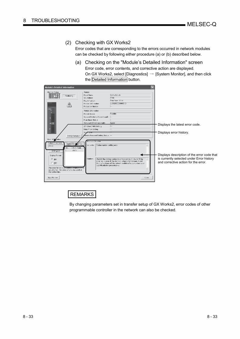
8 - 33 8 - 33
MELSEC-Q 8 TROUBLESHOOTING
(2) Checking with GX Works2
Error codes that are corresponding to the errors occurred in network modules
can be checked by following either procedure (a) or (b) described below.
(a) Checking on the "Module’s Detailed Information" screen Error code, error contents, and corrective action are displayed.
On GX Works2, select [Diagnostics] [System Monitor], and then click the Detailed Information button.
Displays the latest error code.
Displays error history.
Displays description of the error code thatis currently selected under Error historyand corrective action for the error.
REMARKS
By changing parameters set in transfer setup of GX Works2, error codes of other
programmable controller in the network can also be checked.

8 - 34 8 - 34
MELSEC-Q 8 TROUBLESHOOTING
(b) Checking on the "Error History" screen 1
On this screen, errors including those occurred in other modules are
displayed, and the data can be output in a CSV file.
Error code and date and time of error occurrence can be checked even
after powering off and then on the programmable controller or after
resetting the programmable controller CPU.
On GX Works2, select [Diagnostics] [System Monitor], and then click the System Error History button.
1: Available on the programmable controller CPU, network module, and
GX Works2 when their versions are respectively as follows. Item Version
Programmable controller
CPU
Universal model QCPU whose serial number (first five digits) is
"11043" or later
Network module Network module whose serial number (first five digits) is "11042"
or later
GX Works2 Version 1.12N or later
1) Error History List
Error log of the module is displayed.
For errors occurred during initial processing of the programmable controller
CPU, the date and time will be 0000/00/00 00:00:00, therefore the displayed
order under Error history list is not in the order in which the error occurred.
(Example: Station number setting error)
2) Error and Solution, Intelligent Module Information
• Error and Solution
The error description and corrective action for the error, which is currently
selected under "Error History List", are displayed.

8 - 35 8 - 35
MELSEC-Q 8 TROUBLESHOOTING
• Intelligent Module Information
The status of a network module when the error, which is currently selected
under "Error History List", had occurred is displayed. 1 1: When the error that simultaneously occurs with a network error is
selected, the status right before the error occurrence may be displayed
under Intelligent Module Information.
For the network module, the following will be displayed. Item Description
Baton pass status (host) (SW0047) Baton pass status of the host station
Cause of data link stop (SW0049) Cause of data link stop of the host station
Baton pass status of each station (SW0070 to SW0073)
Baton pass status of each station
0: Normal
1: Abnormal
Loopback station (forward loop side)
(SW0099)
Station number of which station is performing a loopback in the forward loop.
For the remote master station, [7DH] is displayed.
Loopback station (reverse loop side)
(SW009A)
Station number of which station is performing a loopback in the reverse loop.
For the remote master station, [7DH] is displayed.
Cyclic transmission status of each
station (SW0074 to SW0077)
Cyclic transmission status of each station
0: Executing cyclic transmission
1: Cyclic transmission not executed
Dedicated instruction Dedicated instruction on which an error has occurred
Target network number Network number of a station to which a dedicated instruction was executed,
resulted in an error
Target station number Station number of a station to which a dedicated instruction was executed,
resulting in an error
3) Create CSV File button
Click this button to output the module error history in a CSV file.
POINT
(1) If errors frequently occur in the network module, "*HST.LOSS*" may be
displayed instead of error codes in the Error Code column.
(Example)
If too many "*HST.LOSS*" are displayed, increase the number of errors to be
collected per scan in the "PLC RAS" tab of the "Q Parameter Setting" dialog
box. For setting, refer to the user’s manual (Function Explanation, Program
Example) for the CPU module used.
(2) When the same errors consecutively occurred, only the error code for the first
occurred is displayed on the "Error History" screen.

8 - 36 8 - 36
MELSEC-Q 8 TROUBLESHOOTING
(3) Checking for data link error
When a data link is not available, check the following link special registers. 1) SW0048: Cause of the baton pass interruption 2) SW0049: Cause of the data link stop 3) SW0055: Parameter setting status
(4) Checking for dedicated instruction error Error codes for the errors occurred during execution of a dedicated instruction can be checked by the following device data. Error codes for transient transmission errors are stored in the link special registers SW00EE to SW00FF as well. For details of each instruction, refer to programming examples for dedicated instructions described in Section 7.4.5 1) SEND, RECV, RECVS, READ, WRITE, REQ:
Completion station (S1) + 1 of the control data 2) ZNRD : SW31 3) ZNWR : SW33 4) RRUN, RSTOP, RTMRD, RTMWR : SW0031 (When channel 1 is used.)
SW0033 (When channel 2 is used.) SW0035 (When channel 3 is used.) SW0037 (When channel 4 is used.) SW0039 (When channel 5 is used.) SW003B (When channel 6 is used.) SW003D (When channel 7 is used.) SW003F (When channel 8 is used.)
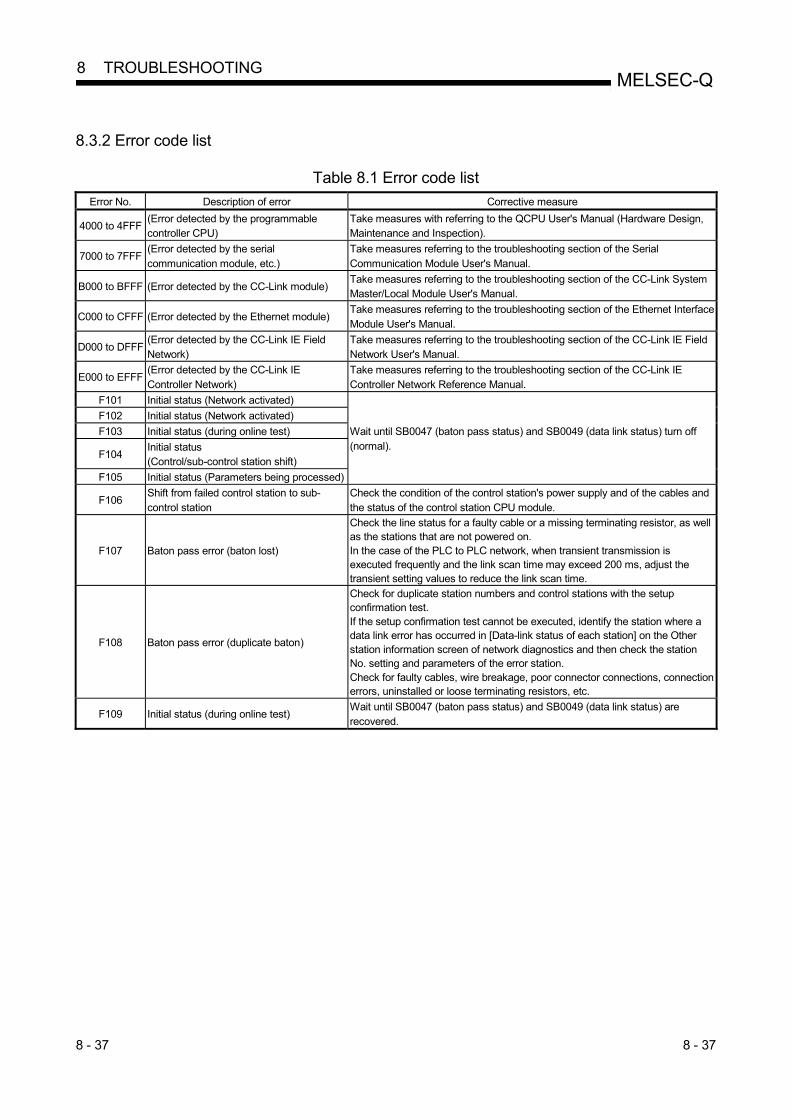
8 - 37 8 - 37
MELSEC-Q 8 TROUBLESHOOTING
8.3.2 Error code list
Table 8.1 Error code list
Error No. Description of error Corrective measure
4000 to 4FFF (Error detected by the programmable controller CPU)
Take measures with referring to the QCPU User's Manual (Hardware Design, Maintenance and Inspection).
7000 to 7FFF (Error detected by the serial communication module, etc.)
Take measures referring to the troubleshooting section of the Serial Communication Module User's Manual.
B000 to BFFF (Error detected by the CC-Link module) Take measures referring to the troubleshooting section of the CC-Link System Master/Local Module User's Manual.
C000 to CFFF (Error detected by the Ethernet module) Take measures referring to the troubleshooting section of the Ethernet Interface Module User's Manual.
D000 to DFFF (Error detected by the CC-Link IE Field Network)
Take measures referring to the troubleshooting section of the CC-Link IE Field Network User's Manual.
E000 to EFFF (Error detected by the CC-Link IE Controller Network)
Take measures referring to the troubleshooting section of the CC-Link IE Controller Network Reference Manual.
F101 Initial status (Network activated)
Wait until SB0047 (baton pass status) and SB0049 (data link status) turn off (normal).
F102 Initial status (Network activated)
F103 Initial status (during online test)
F104 Initial status (Control/sub-control station shift)
F105 Initial status (Parameters being processed)
F106 Shift from failed control station to sub-control station
Check the condition of the control station's power supply and of the cables and the status of the control station CPU module.
F107 Baton pass error (baton lost)
Check the line status for a faulty cable or a missing terminating resistor, as well as the stations that are not powered on. In the case of the PLC to PLC network, when transient transmission is executed frequently and the link scan time may exceed 200 ms, adjust the transient setting values to reduce the link scan time.
F108 Baton pass error (duplicate baton)
Check for duplicate station numbers and control stations with the setup confirmation test. If the setup confirmation test cannot be executed, identify the station where a data link error has occurred in [Data-link status of each station] on the Other station information screen of network diagnostics and then check the station No. setting and parameters of the error station. Check for faulty cables, wire breakage, poor connector connections, connection errors, uninstalled or loose terminating resistors, etc.
F109 Initial status (during online test) Wait until SB0047 (baton pass status) and SB0049 (data link status) are recovered.

8 - 38 8 - 38
MELSEC-Q 8 TROUBLESHOOTING
Table 8.1 Error code list (continued)
Error No. Description of error Corrective measure
F10A Initial status (online test/offline loop test)
<During execution of an online test> Wait until SB0047 (baton pass status) and SB0049 (data link status) are recovered.
<During execution of an offline test> Change the switch setting to online after the test has been completed.
F10B Duplicate station number error
Review the station number setting.
The setup confirmation test of network diagnosis is effective.
If the setup confirmation test cannot be executed, identify the station where a
data link error has occurred in [Data-link status of each station] on the Other
station information screen of network diagnostics and then check the station
No. setting.
F10C Duplicate control station error
Review the station number setting.
The setup confirmation test of network diagnosis is effective.
If the setup confirmation test cannot be executed, identify the station where a
data link error has occurred in [Data-link status of each station] on the Other
station information screen of network diagnostics and then check the
parameters of the error station.
When the operation mode for redundant system is debug, connect one of the
systems to the network. When connecting to both systems to the network, set
the operation mode to back-up mode or to separate mode.
F10D Offline status Review the mode setting, and change it to online.
F10E Number of receive error retries exceeded Check for faulty cables, faulty hardware, incorrect cable wiring, absence of
terminating resistor (in the case of the bus), and duplication of station numbers,
control stations, and remote master stations.
The setup confirmation test and loop test of network diagnosis are effective.
F10F Number of send error retries exceeded
F110 Timeout error
F111
Corresponding station error
(Baton pass to the corresponding station
not executed)
Review the status of the corresponding station and the parameter and switch
settings (to see if there is a parameter error and the corresponding station is the
control station and properly set).
Confirm the power supply status of the corresponding station (to see if it is
repeatedly turned on and off).
Check for faulty cables, faulty hardware, incorrect cable wiring, absence of
terminating resistor (in the case of the bus), and duplication of station numbers,
control stations, and remote master stations.
The setup confirmation test and loop test of network diagnosis are effective.
F112 Faulty loop status
Check for faulty cables, faulty hardware, incorrect wiring, and duplication of
station numbers, control stations, and remote master stations.
Confirm the power supply status of each module (to see if it is repeatedly
turned on and off).
Confirm whether network modules in MESLECNET/H and MELSECNET/10
modes exist together (confirm the control station type).
F113
Send failure
(Baton pass to the host station not
executed)
Retry after a little while.
If the error reoccurs as a result of a retry, check for faulty cables, faulty
hardware, incorrect cable wiring, absence of terminating resistor (in the case of
the bus), and duplication of station numbers, control stations, and remote
master stations.
Wait until SB0047 (baton pass status) and SB0049 (data link status) are
recovered.
F114 Send failure
Retry after a little while.
If the error reoccurs as a result of a retry, check for faulty cables, faulty
hardware, incorrect cable wiring, absence of terminating resistor (in the case of
the bus), and duplication of station numbers, control stations, and remote
master stations.
Wait until SB0047 (baton pass status) and SB0049 (data link status) are
recovered.
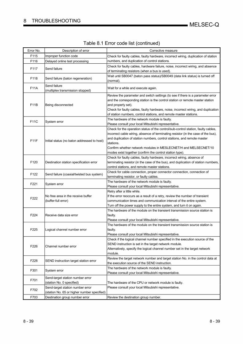
8 - 39 8 - 39
MELSEC-Q 8 TROUBLESHOOTING
Table 8.1 Error code list (continued)
Error No. Description of error Corrective measure
F115 Improper function code Check for faulty cables, faulty hardware, incorrect wiring, duplication of station
numbers, and duplication of control stations. F116 Delayed online test processing
F117 Send failure Check for faulty cables, hardware failure, noise, incorrect wiring, and absence
of terminating resistors (when a bus is used).
F118 Send failure (baton regeneration) Wait until SB0047 (baton pass status)/SB0049 (data link status) is turned off
(normal).
F11A Send failure
(multiplex transmission stopped) Wait for a while and execute again.
F11B Being disconnected
Review the parameter and switch settings (to see if there is a parameter error
and the corresponding station is the control station or remote master station
and properly set).
Check for faulty cables, faulty hardware, noise, incorrect wiring, and duplication
of station numbers, control stations, and remote master stations.
F11C System error The hardware of the network module is faulty.
Please consult your local Mitsubishi representative.
F11F Initial status (no baton addressed to host)
Check for the operation status of the control/sub-control station, faulty cables,
incorrect cable wiring, absence of terminating resistor (in the case of the bus),
and duplication of station numbers, control stations, and remote master
stations.
Confirm whether network modules in MESLECNET/H and MELSECNET/10
modes exist together (confirm the control station type).
F120 Destination station specification error
Check for faulty cables, faulty hardware, incorrect wiring, absence of
terminating resistor (in the case of the bus), and duplication of station numbers,
control stations, and remote master stations.
F122 Send failure (coaxial/twisted bus system) Check for cable connection, proper connector connection, connection of
terminating resistor, or faulty cables.
F221 System error The hardware of the network module is faulty.
Please consult your local Mitsubishi representative.
F222 No free area in the receive buffer
(buffer-full error)
Retry after a little while.
If the error reoccurs as a result of a retry, review the number of transient
communication times and communication interval of the entire system.
Turn off the power supply to the entire system, and turn it on again.
F224 Receive data size error
The hardware of the module on the transient transmission source station is
faulty.
Please consult your local Mitsubishi representative.
F225 Logical channel number error
The hardware of the module on the transient transmission source station is
faulty.
Please consult your local Mitsubishi representative.
F226 Channel number error
Check if the logical channel number specified in the execution source of the
SEND instruction is set in the target network module.
Alternatively, specify the logical channel number set in the target network
module.
F228 SEND instruction target station error Review the target network number and target station No. in the control data at
the execution source of the SEND instruction.
F301 System error The hardware of the network module is faulty.
Please consult your local Mitsubishi representative.
F701 Send-target station number error
(station No. 0 specified) The hardware of the CPU or network module is faulty.
Please consult your local Mitsubishi representative. F702
Send-target station number error
(station No. 65 or higher number specified)
F703 Destination group number error Review the destination group number.

8 - 40 8 - 40
MELSEC-Q 8 TROUBLESHOOTING
Table 8.1 Error code list (continued)
Error No. Description of error Corrective measure
F706 Received data size error
The cable is faulty, or The hardware of the network module is faulty.
If a communication error has occurred, review the cable.
If not, the hardware of the network module is faulty.
Please consult your local Mitsubishi representative.
F707 Number of relay stations invalid
Set stations to which data can be sent.
Review the system.
Review the routing parameters.
F708 Receiving group number error Review the group number of the target station.
F709 Receiving network number error
Review the network No. of network parameter for a host station and a target
station.
If the parameter is not set, the network No. is preset to 1 (default); so check the
network No. of other stations.
F70A System error
The cable is faulty, or the hardware of the network module is faulty.
If a communication error has occurred, review the cable.
If not, the hardware of the network module is faulty.
Please consult your local Mitsubishi representative.
F70B Response wait timeout Wait until SB0047 (baton pass status) and SB0049 (data link status) are
recovered.
F70C System error The cable is faulty, or the hardware of the network module is faulty.
If a communication error has occurred, review the cable.
If not, the hardware of the network module is faulty.
Please consult your local Mitsubishi representative. F70E System error
F710 System error The hardware of the network module is faulty.
Please consult your local Mitsubishi representative. F711 System error
F712 System error
F781 Connection target specification error
Check if C24 connection or CC-Link connection is specified for access to other
stations.
If the setting is correct, the hardware of the CPU or network module is faulty.
Please consult your local Mitsubishi representative.
F782 System error The hardware of the CPU or network module is faulty.
Please consult your local Mitsubishi representative.
F783 System error The hardware of the network module is faulty.
Please consult your local Mitsubishi representative.
F7C1 Host station channel in use
The same channel cannot be used at the same time.
Change the channel number.
Alternatively, do not use the same channel at the same time.
F7C2 Target station channel in use
Retry the SEND instruction after a little while.
Check if the target station uses the channel concerned to execute the
instruction, or if RECV processing is executed.
Check if another station executes the SEND instruction to the target station's
channel.

8 - 41 8 - 41
MELSEC-Q 8 TROUBLESHOOTING
Table 8.1 Error code list (continued)
Error No. Description of error Corrective measure
F7C3 Arrival monitoring timeout
<When this error occurs by the ZNRD/ZNWR instruction>
When a CPU module on another station to be accessed is an A2UCPU(S1),
A3UCPU, A4UCPU, A2ASCPU(S1), or A2USCPU(S1), use the CPU module
with the following version or later. A2UCPU(S1), A3UCPU, A4UCPU: Version AY (manufactured since July,
1995) or later A2ASCPU(S1), A2USCPU(S1): Version CP (manufactured since July, 1995)
or later
<When this error occurs by the RECV instruction>
When another station is executing the SEND instruction, increase the value of
the arrival monitoring time.
Alternatively, start the RECV instruction by turning the RECV instruction
execution request flag to ON.
<When this error occurs in other cases>
Increase the value of the arrival monitoring time.
Confirm the operation status of the target station, the network status, and the
relay station status (in the case of sending to other network).
F7C4 Resend count-out
Increase the arrival monitoring time.
Re-execute the REMFR/REMTO instruction.
Confirm the operation status of the target station, the network status, and the
relay station status (in the case of sending to other network).
F7C5 SEND instruction target station error Review the target network number and target station No. in the request control
data of send/receive instructions.
F7C6 Channel number setting out of range
Set the channel numbers of the host station and of the target station in the
request control data of send/receive instructions within a range between 1 and
64.
F7C7 Target station specification error
(host station specification)
Specify the target station number in the request control data of send/receive
instructions to other than the number of host station.
F7C8 Execution type specification error
When the execution/abnormal completion type in the request control data of
send/receive instructions is specified for all stations or groups, set "No arrival
confirmation" for the execution type.
F7C9 Resend count setting out of range Set the resent count of the request control data of send/receive instructions
within a range between 0 and 15 (times).
F7CA Arrival monitoring time setting out of range Set the arrival monitoring time of the request control data of send/receive
instructions within a range between 0 and 32767 (seconds).
F7CB Sent data length setting out of range
(SEND instruction)
Set the sent data length of the request control data of the SEND instruction
within a range between 1 and 960 (words).
F7CD System error The hardware of the network module is faulty.
Please consult your local Mitsubishi representative.
F7E1 Control data error Confirm the set values (mode, etc.) in the control data of a dedicated
instruction.
F7E2 System error The hardware of the network module is faulty.
Please consult your local Mitsubishi representative. F7E3 System error
F7E4 Target CPU module type error
Check if the CPU module model of the target station specified in the WRITE,
READ, REQ, RRUN, RSTOP, RTMRD, and RTMWR instructions is out of
applicable range.
F7E5 Post-transmission event wait timer time-out
Re-execute the REMFR or REMTO instruction after a little while.
Confirm the operation status of the target station, the network status, and the
relay station status (in the case of sending to other network).
F7E7 Buffer memory address error Check if the buffer memory address specified in the REMFR and REMTO
instructions exceeds 8000H.
F7E8 Network type error Check if the network number specified in the REMFR and REMTO instructions
represents a PLC to PLC network.
F7E9 Instruction not executable error Check if the host station is data-linked when the REMFR or REMTO instruction
is executed.

8 - 42 8 - 42
MELSEC-Q 8 TROUBLESHOOTING
Table 8.1 Error code list (continued)
Error No. Description of error Corrective measure
F800 Mode switch setting error
Confirm the setting of the mode switch. 1
If the error reoccurs after resetting, the hardware of the network module is
faulty.
Please consult your local Mitsubishi representative.
F801 Network number setting error Create new network parameters and perform Write to PLC.
If the error reoccurs, the hardware of the CPU or network module is faulty.
Please consult your local Mitsubishi representative. F802 Group number error
F803 Station number setting error
Check if the station number is within a range of 1 to 64.
If the error reoccurs even if the station number is set between 1 and 64, the
hardware of the network module is faulty.
Please consult your local Mitsubishi representative.
F804 DIP switch setting error
Create new network parameters and perform Write to PLC.
If the error reoccurs, the hardware of the CPU or network module is faulty.
Please consult your local Mitsubishi representative.
F805 System error The hardware of the network module is faulty.
Please consult your local Mitsubishi representative.
F806 System error The hardware of the CPU or network module is faulty.
Please consult your local Mitsubishi representative.
F808 System error
The hardware of the network module is faulty.
Please consult your local Mitsubishi representative.
F80A System error
F80B System error
F80C System error
F80D System error
F80E System error
F80F System error
F811 System error
F812 System error
F813 Parameter data error (parameter)
Replace the network module of the control or normal station with the one
compatible with the MELSECNET/H Extended mode.
Change the network type of the normal station to that of the control station.
Create new network parameters and perform Write to PLC.
If the error reoccurs, the hardware of the CPU or network module is faulty.
Please consult your local Mitsubishi representative.
F814 Parameter data error (code)
Create new network parameters and perform Write to PLC.
If the error reoccurs, the hardware of the CPU or network module is faulty.
Please consult your local Mitsubishi representative.
F820 Link parameter error
Replace the network module of the normal station with the one compatible with
the MELSECNET/H Extended mode.
Change the network type of the normal station to that of the control station.
Create new network parameters and perform Write to PLC.
When the MELSECNET/H twisted bus system is configured, check that the
MNET/10 mode is not selected as the network type and either of the forward
loop and reverse loop test is not selected as the mode.
If any of above mentioned parameter is set, create new network parameters
and perform Write to PLC.
If the error reoccurs, the hardware of the CPU or network module is faulty.
Please consult your local Mitsubishi representative.
F821 Station-specific parameter error
Review station-specific parameters. Set common parameters station-specific parameters for the sending range of the host station. If no station-specific parameters are set, the hardware of the CPU or network module is faulty. Please consult your local Mitsubishi representative.
1: For the QJ71NT11B, check the station number/mode setting switch.

8 - 43 8 - 43
MELSEC-Q 8 TROUBLESHOOTING
Table 8.1 Error code list (continued)
Error No. Description of error Corrective measure
F822 System error The hardware of the CPU or network module is faulty. Please consult your local Mitsubishi representative.
F823 Parameter consistency error
Set common parameters station-specific parameters for the sending range of the host station. If no station-specific parameters are set, the hardware of the CPU or network module is faulty. Please consult your local Mitsubishi representative.
F825 CPU parameter check error Perform Write to PLC on the network parameters for the control station again. If the error reoccurs, the hardware of the CPU or network module is faulty. Please consult your local Mitsubishi representative.
F826 Parameter mismatch error
Set parameters suitable for the sub control station, or activate it as a control station. Review and reset the parameters for the master and sub master stations. If the error reoccurs, the hardware of the CPU or network module is faulty. Please consult your local Mitsubishi representative.
F828 No control station shift setting Set "with data link by the sub control station when the control station is down."
F829 Pairing setting error On the network parameter at control station, set the pairing setting on the Redundant CPU or unset the pairing setting on all the CPUs other than the Redundant CPU.
F82A Network type mismatch (normal station detected) Match the network type set for the normal station with the one set for the control
station. F82B
Network type mismatch (control station detected)
F830 System error The hardware of the CPU or network module is faulty. Please consult your local Mitsubishi representative. F831 System error
F832 Data link startup condition error
If the data link is stopped under all station specification, start it by all station specification. If the data link is stopped under specific station specification, start it from the station, or forcibly start it.
F833 Keyword error Start the data link from the station where it was discontinued, or forcibly start it.
F834 System error The cable is faulty, or the hardware of the network module is faulty. If a communication error has occurred, review the cable. If not, the hardware of the network module is faulty. Please consult your local Mitsubishi representative.
F835 System error
F836 System error
F837 Exceeded number of retries Check the status of the control station and of the remote master station (to see if resetting or an error occurs in the middle of the operation).
F838 Relevant timer timeout Check the status of the control station and of the remote master station (to see if resetting or an error occurs in the middle of the operation).
F839 No link parameter (communication impossible)
Register link parameters
F83A SW0000 out of range error Correct the contents of SW0000.
F83B Forced switching impossible error
Check if the following conditions are met: The system is a multiplexed remote I/O network system. Check if "Return as a standby station" is set as the parameter for the master
station. The host station is operating as a master station. The operating sub master station is in data-linking.
F840 Low speed cyclic parameter error Create new network parameters and perform Write to PLC. If the error reoccurs, the hardware of the CPU or network module is faulty. Please consult your local Mitsubishi representative.
F841 System error
F842 System error
Create new network parameters and perform Write to PLC.
If the error reoccurs, the hardware of the CPU or network module is faulty.
Please consult your local Mitsubishi representative.
F843 System error
Create new network parameters and perform Write to PLC.
If the error reoccurs, the hardware of the CPU or network module is faulty.
Please consult your local Mitsubishi representative.

8 - 44 8 - 44
MELSEC-Q 8 TROUBLESHOOTING
Table 8.1 Error code list (continued)
Error No. Description of error Corrective measure
F901 System error The hardware of the network module is faulty.
Please consult your local Mitsubishi representative.
F902 System error Check the system configuration to see if there are eight or more relay networks
in the MELSECNET/H.
F903 System error The hardware of the CPU or network module is faulty.
Please consult your local Mitsubishi representative. F904 System error
F905 System error The hardware of the network module is faulty.
Please consult your local Mitsubishi representative.
FD01 CRC error (offline test)
There is no need to take corrective measures because the system retries the
operation.
If the error frequently occurs, check for faulty cables, faulty hardware, noise,
absence of terminating resistor (in the case of the bus), and incorrect wiring.
FD02 Overrun error (offline test)
FD03 AB. IF error (offline test)
FD04 TIME error (offline test)
FD05 Data error (offline test)
FD06 Under error (offline test)
FD07 Send failure
FD08 Send failure (coaxial/twisted bus system) Check if the cable is not connected or is loose or faulty and if the terminating
resistor is not connected.
FD09 Loop status changed (offline loop test) There is no need to take corrective measures because the system retries the
operation (do not switch the loop in the middle of the operation).
If the error frequently occurs, check the line and the wiring status. FD0A Unstable communication (offline loop test)
FD0B Wiring error (offline loop test) Check the wiring.
FD0C System error There is a problem with the hardware of the network module.
Please consult your local Mitsubishi representative.
FD11 Error occurred during test execution Execute after the completion of the test from other station.
FD12 Disconnecting error Review the cause for why the station is being disconnected.
FD13 System error Set the total number of link stations with a common parameter.
Set a station number that is equal to the host station number or larger.
FD14 System error
The hardware of the network module is faulty.
Please consult your local Mitsubishi representative.
FD15 System error
FD16 System error
FD17 System error
FD18 System error
FD19 System error
FD1A Station with duplicated station number Check the duplicate station number, and correct it.
FD1B Test abort error
The ongoing test was interrupted due to the resetting of the test executing
station.
There is a faulty station on the networks.
FD1C Interruption error due to loop switching
during test
There is no need to take corrective measures because the system retries the
operation (do not switch the loop in the middle of the operation).
If the error frequently occurs, check the line and the wiring status.
FD1D System error The hardware of the network module is faulty.
Please consult your local Mitsubishi representative.
FD1E Bus topology, test disabled error Conduct a test that can be executed in the bus topology.
FD20 Mode error
Create new network parameters and perform Write to PLC.
If the error reoccurs, the hardware of the CPU or network module is faulty.
Please consult your local Mitsubishi representative.
FD21 Hardware error (send interrupt error) The cable was disconnected during the online test.
Reconnect the cable, and continue the online test. FD22 Hardware error (receive interrupt error)
FD23 Data comparison error Check for faulty cables, faulty hardware, incorrect wiring, absence of
terminating resistor (in the case of the bus), and duplication of station numbers,
and control stations. FD24 Retry over
FD25 Input port initial value check error The hardware of the network module is faulty.
Please consult your local Mitsubishi representative.
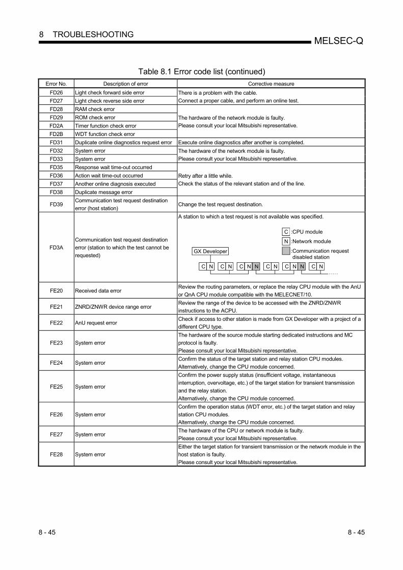
8 - 45 8 - 45
MELSEC-Q 8 TROUBLESHOOTING
Table 8.1 Error code list (continued)
Error No. Description of error Corrective measure
FD26 Light check forward side error There is a problem with the cable.
Connect a proper cable, and perform an online test. FD27 Light check reverse side error
FD28 RAM check error
The hardware of the network module is faulty.
Please consult your local Mitsubishi representative.
FD29 ROM check error
FD2A Timer function check error
FD2B WDT function check error
FD31 Duplicate online diagnostics request error Execute online diagnostics after another is completed.
FD32 System error The hardware of the network module is faulty.
Please consult your local Mitsubishi representative. FD33 System error
FD35 Response wait time-out occurred
Retry after a little while.
Check the status of the relevant station and of the line.
FD36 Action wait time-out occurred
FD37 Another online diagnosis executed
FD38 Duplicate message error
FD39 Communication test request destination
error (host station) Change the test request destination.
FD3A
Communication test request destination
error (station to which the test cannot be
requested)
A station to which a test request is not available was specified.
GX Developer
C
N
C C C C C CN N N N N N N N
:CPU module
:Network module
:Communication request disabled station
FE20 Received data error Review the routing parameters, or replace the relay CPU module with the AnU
or QnA CPU module compatible with the MELECNET/10.
FE21 ZNRD/ZNWR device range error Review the range of the device to be accessed with the ZNRD/ZNWR
instructions to the ACPU.
FE22 AnU request error Check if access to other station is made from GX Developer with a project of a
different CPU type.
FE23 System error
The hardware of the source module starting dedicated instructions and MC
protocol is faulty.
Please consult your local Mitsubishi representative.
FE24 System error Confirm the status of the target station and relay station CPU modules.
Alternatively, change the CPU module concerned.
FE25 System error
Confirm the power supply status (insufficient voltage, instantaneous
interruption, overvoltage, etc.) of the target station for transient transmission
and the relay station.
Alternatively, change the CPU module concerned.
FE26 System error
Confirm the operation status (WDT error, etc.) of the target station and relay
station CPU modules.
Alternatively, change the CPU module concerned.
FE27 System error The hardware of the CPU or network module is faulty.
Please consult your local Mitsubishi representative.
FE28 System error
Either the target station for transient transmission or the network module in the
host station is faulty.
Please consult your local Mitsubishi representative.

8 - 46 8 - 46
MELSEC-Q 8 TROUBLESHOOTING
Table 8.1 Error code list (continued)
Error No. Description of error Corrective measure
FE30 System error
The hardware of the network module is faulty.
Please consult your local Mitsubishi representative.
FE31 System error
FE32 System error
FE34 System error
FE36 System error
FE37 System error
FE38 System error
FE39 System error The hardware of the CPU or network module is faulty.
Please consult your local Mitsubishi representative.
FE3B System error
The hardware of the network module is faulty.
Please consult your local Mitsubishi representative.
FE3C System error
FE3D System error
FE3E System error
FE3F System error

8 - 47 8 - 47
MELSEC-Q 8 TROUBLESHOOTING
8.4 H/W Information
With the H/W information, details of the LED and switch information of the network
modules can be monitored using GX Developer. To display the H/W information, click
the H/W information button on the system monitor screen of GX Developer.
The H/W information is displayed on the screen shown below with a combination of the
network module's function version and the GX Developer's function version.
(1) When the network module: function version B and the GX
Developer: SW7D5C-GPPW are combined
1)
1)-a
1)-b
2)-b
2)-a
The following details will be displayed for each item.
1) H/W LED information
Displays the LED information for the network module.
The values for each item is displayed as: 0001 on, 0000 off. Item Description
RUN Module operating normally: on
PC With PLC to PLC networks: on
REMOTE With remote I/O networks: on
DUAL During multiplex transmission execution: on
SW.E During switch setting errors: on
M/S.E. When station numbers or controlled stations are duplicated on the same network: on
PRM.E. When an integrity error is triggered with a common parameter and a station's unique
parameter, and when the parameter received from a sub-controlled station is different to the
host parameter received from the controlled station: on
MNG During controlled station setup: on
During normal station setup: off
S.MNG When it does not exist in a sub-controlled station: on
D.LINK During data links (cyclic transmission is being executed): on
T.PASS Executing baton pass (being joined in a network): on

8 - 48 8 - 48
MELSEC-Q 8 TROUBLESHOOTING
Item Description
CRC During received data code check errors: Illuminated
1)-a: Forward loop side, 1)-b: Reverse loop side
OVER During delayed received data processing errors: Illuminated
1)-a: Forward loop side, 1)-b: Reverse loop side
AB.IF. When errors are triggered owing to values other than the stipulated "1" are received
consecutively, and when errors are triggered owing to the length of the received data being too
short: Illuminated
1)-a: Forward loop side, 1)-b: Reverse loop side
TIME When errors are triggered owing to the data link monitoring timer being activated: Illuminated
1)-a: Forward loop side, 1)-b: Reverse loop side
DATA When errors are triggered owing to abnormal data exceeding 2kbytes has been received:
Illuminated
1)-a: Forward loop side, 1)-b: Reverse loop side
UNDER When errors are triggered owing to the internal processing of transmission data not being
completed within the specified period of time: Illuminated
1)-a: Forward loop side, 1)-b: Reverse loop side
LOOP When errors are triggered owing abnormalities on the loop: Illuminated
1)-a: Forward loop side, 1)-b: Reverse loop side
2) H/W switch information
Displays the switch information for the network module.
2)-a: Displays the switch settings for the H/W mounted on the network
module. Item Description
STx10 Position 10 of the station number setting switch
STx1 Position 1 of the station number setting switch
MODE Mode setting switch
2)-b: Displays the switch information actually set up on the network module. Item Description Display range
NETNO. Network number setting 0 to 239
GRPNO. Group number setting 0 to 9
STNO. Station number setting 1 to 64
MODE Operation mode setting 0: On-line
7: Self loop-back test
8: Internal self loop-back test
9: Hardware test
BAUD Communication speed Optical loop Coaxial bus Twisted bus
0: 10 Mbps
1: 25 Mbps
0: 10 Mbps 0: 156Kbps
1: 312Kbps
2: 625Kbps
3: 1.25Mbps
4: 2.5Mbps
5: 5Mbps
6: 10Mbps
CONFIG Station type, controlled station operations
during recovery, transmission mode settings
b15 b8 b7 b0
All "0"
b5
Empty
Controlled station operations 0: Switched 1: Not switched
Transmission mode 0: On-line mode (start) 1: Debug mode (stop)
Station type 0: Normal station 1: Controlled station

8 - 49 8 - 49
MELSEC-Q 8 TROUBLESHOOTING
(2) When the network module: function version B and the GX
Developer: prior to SW5D5C-GPPW are combined
1)
2)
3)
4)
5)
6)
7)
8)
9)
10)
12)
11)
The following details will be displayed for each item.
1) Actual LED1 information
Displays the illumination status of LEDs actually mounted onto the network
module.
T.PASSSD
ERR.
MNGD.LINK
RD
L ERR.
RUN
b15 b8 b7 b0
All "0"
1: Illuminated0: Extinguished
2) LED1 information
Displays information for illuminated LEDs on the network module. The
following details are displayed.
(Refer to section 8.4 (1) for details of the information for all LEDs.)
PCREMOTE
DUAL
SW.E.
M/S.E.PRM.E.
CRC
b15 b8 b7 b0
1: Illuminated0: Extinguished
0 (Fixed)
OVERAB.IF.
TIMEDATA
UNDERLOOP
0 (Fixed)

8 - 50 8 - 50
MELSEC-Q 8 TROUBLESHOOTING
3) LED2 information
Displays information for illuminated LEDs on the network module. The
following details are displayed.
(Refer to section 8.4 (1) for details of the information for all LEDs.)
MNGS.MNG
D.LINK
T.PASS
CRC
b15 b8 b7 b0
1: Illuminated0: Extinguished
0 (Fixed)
OVERAB.IF.
TIMEDATA
UNDERLOOP
0 (Fixed)
0 (Fixed)
4) Actual switch 1 information
Displays the station number (position 10) set with the station number setting
switch (position 10) mounted onto the network module.
5) Actual switch 2 information
Displays the station number (position 1) set with the station number setting
switch (position 1) mounted onto the network module.
6) Actual switch 3 information
Displays the mode number set with the mode setting switch mounted onto
the network module.
7) Network number switch information
Displays the number of the network actually set on the network module.
Display range: 0 to 239
8) Group number switch information
Displays the number of the group actually set on the network module.
Display range: 0 to 32
9) Station number switch information
Displays the number of the station actually set on the network module.
Display range: 0 to 64
10) Mode number switch information
Displays the number of the mode actually set on the network module.
Display range: 0 to F
11) For future expansion purposes

8 - 51 8 - 51
MELSEC-Q 8 TROUBLESHOOTING
12) Dip number switch information
Displays the station type, the controlled station operations during recovery,
and the Send mode set up in the network module.
b15 b8 b7 b0
All "0"
b5
EmptyControl station operation0: Switched1: Not switched
Send mode0: Online mode (start)1: Debug mode (stop)
Station type0: Normal station1: Control station
(3) When the network module: function version A and the GX Developer: prior to SW5D5C-GPPW are combined
1)
2)
3)
4)
5)
6)
7)
8)
9)
10)
11)
Each item displays the following information.
1) Actual LED1 information
Displays the on/off status of the LEDs that are used in the network module.
T.PASSSD
ERR.
MNG
D.LINKRD
L ERR.
RUN
b15 b8 b7 b0
All "0"
1: On
0: Off 2) LED1 information
Displays the information of the LEDs that are turned on by the network
module. The contents are displayed in the following manner:
• "UNDER RUN forward loop" to "CRC forward loop" display the information
of errors that have occurred on the forward loop side. The "L ERR." of 1)
Actual LED1 information turns on if either one of these errors have
occurred (corresponding LED information turns on) or the "UNDER RUN
reverse loop" to "CRC reverse loop" LED information of 3) LED2
information is lit.
• The "ERR." signal of 1) Actual LED1 information turns on if either
"Parameter setting error," "Duplicate station number/control station error"
or "Switch setting error" of 4) LED3 information is lit.

8 - 52 8 - 52
MELSEC-Q 8 TROUBLESHOOTING
DATA forward loopTIME forward loop
ABORT IN-FR forward loop
OVER RUN forward loopCRC forward loop
Parameter setting error
Duplicate station number/control station error
UNDER RUN forward loop
b15 b8 b7 b0
All "0"
1: On0: Off
3) LED2 information
Displays the information of the LEDs that are turned on by the network
module. The contents are displayed in the following manner:
• "UNDER RUN reverse loop" to "CRC reverse loop" display information of
errors that have occurred on the reverse loop side. The "L ERR." of 1)
Actual LED1 information turns on if either one of these errors have occurred
(corresponding LED information turns on) or the "UNDER RUN forward
loop" to "CRC forward loop" LED information of 2) LED1 information is lit.
Furthermore the "Forward loop error" turns on if either of "UNDER RUN
forward loop" to "CRC forward loop" is on. The "Reverse loop error" turns
on if either of "UNDER RUN reverse loop" to "CRC reverse loop" is on.
DATA reverse loopTIME reverse loop
ABORT IN-FR reverse loop
OVER RUN reverse loopCRC reverse loop
Forward loop error
Reverse loop error
UNDER RUN reverse loop
b15 b8 b7 b0
All "0"
1: On
0: Off
4) LED3 information
Displays the information of the LEDs that are turned on by the network
module. The contents are displayed in the following manner:
• "T.PASS" turns on during baton pass. When this LED information turns on,
the "T.PASS" of 1) Actual LED1 information is turned on.
• "D.LINK" turns on during data linking. When this LED information turns on,
the "D.LINK" of 1) Actual LED1 information is turned on.
• "S.MNG" and "MNG" turn on when the network module is being controlled
by the sub-control station and the control station, respectively. When
either of this LED information turns on, the "MNG" of 1) Actual LED1
information is turned on.
• "ERR" of 1) Actual LED1 information turns on if either "Parameter setting
error" or "Duplicate station number/control station error" of 2) LED1
information, or the "Switch setting error" is on.
• "PC" turns on when the network module is operating on PLC to PLC
network. (1: fixed)
D.LINKS.MNG
MNG
Switch setting error
Unused "0"Unused "0"
PC
T.PASS
b8 b7 b0
All "0"
1: On0: Off

8 - 53 8 - 53
MELSEC-Q 8 TROUBLESHOOTING
5) Actual switch information
Displays the station number and mode number that are set by the hardware
switch mounted on the network module. b15 b8 b7 b0
All "0"
b9b10 b5
Station number
11: Online
10: Self-loopback01: Internal self-loopback
00: Hardware test
6) Network No. switch information
Displays the network No. set for the network module.
Display range: 0 to 239 7) Group number switch information
Displays the group number set for the network module.
Display range: 0 to 32 8) Station number switch information
Displays the station number set for the network module.
Display range: 0 to 64 9) Mode number switch information
Displays the mode number set for the network module.
Display range: 0 to F 10) For future expansion 11) DIP number switch information
Displays the station type, control station operation when returning to the
network, and send mode. The contents are displayed in the following
manner.
b15 b8 b7 b0
All "0"
b5
EmptyControl station operation0: Switched1: Not switched
Send mode0: Online mode (start)1: Debug mode (stop)
Station type0: Normal station1: Control station

App - 1 App - 1
MELSEC-Q APPENDICES
APPENDICES
Appendix 1 Comparison of Network Module Specifications, and Compatibility Appendix 1.1 List of comparison between MELSECNET/H and MELSECNET/H Extended
mode and MELSECNET/10 mode specifications
The MELSECNET/H system supports the MELSECNET/H and MELSECNET/H Extended modes (high functionality/high-speed mode) and the MELSECNET/10 mode (functional and performance compatibility mode), which are explained in this manual. When the MELSECNET/10 mode is used, it is easy to make connection with the AnU/QnA corresponding MELSECNET/10. However, its specifications are different from those of the MELSECNET/10 mode, as shown in Table 1 below. Since this manual is written assuming that MELSECNET/H is used in the MELSECNET/H and MELSECNET/H Extended mode, refer to the "QnA/Q4AR Corresponding MELSECNET/10 Network System Reference Manual" to use it in the MELSECNET/10 mode.
Table 1 Comparison of specifications among MELSECNET/H mode, MELSECNET/H Extended mode and MELSECNET/10 mode
Selected mode
Specification item
MELSECNET/H network system MELSECNET/H mode, MELSECNET/H
Extended mode MELSECNET/10 mode
Transmission type Coaxial bus type/optical (SI) loop type
Maximum number of link points
I/O (LX, LY) 8192 points Link relay (LB) 16384 points 8192 points Link register (LW) 16384 points 8192 points
Maximum number of link points per station 1
[MELSECNET/H mode] {(LY+LB)/8 + (2 LW)} 2000 bytes
[MELSECNET/H Extended mode] {(LY+LB)/8 + (2 LW)} 35840 bytes
{(LY+LB)/8 + (2 LW)} 2000 bytes
Transient transmission data size Maximum 1920 bytes/frame Maximum 960 bytes/frame Communication speed 25 Mbps/10 Mbps (from switch setting) 10 Mbps
Link scan time
[MELSECNET/H mode, communication speed 10Mbps]
KB + (0.45 total stations) + (total number of bytes used by network 0.001) (ms)
KB + (0.75 total number of stations) + (total number of bytes used in the network
0.001) (ms)
Transmission delay time
Sequence scan time of sending side + refresh time of sending side
+ LS 1 + sequence scan time of receiving side 2
+ refresh time of receiving side
Sequence scan time of sending side + refresh time of sending side
+ LS 2 + sequence scan time of receiving side 2
+ refresh time of receiving side Communication method Token bus method [coaxial bus type]/token ring method [optical loop type]
Overall distance 500 m (1640.5 ft.) [coaxial bus type]/30 km (98430 ft.) [optical loop type]
2.5 km (8202.5 ft.) : When 4 repeaters are connected
Distance between stations
[optical loop type (Communication speed 10 Mbps)] 1 km (3281 ft.) : When QSI/Broad-band H-PCF/H-PCF cable is used 500 m (1640.5 ft.) : When SI cable is used
[coaxial bus type] 500 m (1640.5 ft.) : 5C-2V, 5C-FB 300 m (984.3 ft.) : 3C-2V
Maximum number of networks 239 Maximum number of groups 32 9
Maximum number of connected stations 32 stations (1: control station, 31: normal stations) [coaxial bus type]/ 64 stations (1: control station, 63: normal stations) [optical loop type]
Maximum number of modules installed per CPU Total of 4 modules (Basic model CPU, Q00UJCPU, Q00UCPU, Q01UCPU, and safety CPU:
1 module) 32 bits data assurance Supported Not supported
Station-based block data assurance Supported Supported (Only for stations connected to the QCPU when the QCPU is the control station)
Transient transmission function N:N communication (monitor, upload/download, etc.) Supported
Number of data sending/receiving channels Receive channels: 64
(up to 8 channels when used at the same time) Send channels: 8
8 (fixed channels)
Compatible instructions (SEND, RECV, READ, SREAD, WRITE, SWRITE, REQ, ZNRD, ZNWR)
Available
RRUN, RSTOP, RTMRD, RTMWR instruction Available RECVS instruction Available Not available
1: The number of LY points of the stations set in the I/O master station is the sum total of the LY points for output to all stations within the block.
A

App - 2 App - 2
MELSEC-Q APPENDICES
Selected mode
Specification item
MELSECNET/H network system MELSECNET/H mode, MELSECNET/H
Extended mode MELSECNET/10 mode
Low-speed cyclic transmission function Yes No
Maximum number of refresh parameters that can be set (excluding SB, SW)
Item
Number of settings
Basic model QCPU
Safety CPU
Q00UJCPU Q00UCPU Q01UCPU
High Performance model QCPU Process CPU
Redundant CPU Universal model QCPU other than
indicated in the left column Link device transfer 8 16 64 SB/SW transfer 1 for each
Network connection applicable CPU
QCPU (Q mode)
QCPU (Q mode) QCPU-A (A mode)
QnACPU ACPU
A

App - 3 App - 3
MELSEC-Q APPENDICES
Appendix 1.2 Upgraded functions of the network module
The network module undergoes the addition of functions and specification changes by
version upgrade.
For checking of the function version of the network module, refer to Section 2.3. (1) Compatibility with old models
When replacing a previous network module (function version A or B) with the one
of function version D, there is no need to change the parameters, programs, and
switch settings.
However, to use any function not available for a previous version, the parameters
and programs must be modified. (2) Additional functions
The table below shows the functions added to function version B or later.
Additional function Description Function version
A B D Multiple CPU system supported
Multiple CPU systems are supported.
Addition of link dedicated instructions
The following link dedicated instructions were added: • RRUN instruction (remote RUN instruction) • RSTOP instruction (remote STOP instruction) • RTMRD instruction (other station's clock data read instruction) • RTMWR instruction (other station's clock data write instruction)
Data length of link dedicated instructions increased to 960 words
The data length of the following link dedicated instructions was increased from 460 words to 960 words: • SEND instruction • RECV instruction • RECVS instruction • READ/SREAD instructions • WRITE/SWRITE instructions
Redundant system supported
• The network module can be mounted on the base unit of the redundant system and used (redundant network module).
• A system switching request is automatically issued to the control system CPU in case of a data link error or malfunction.
Target station CPU type designation in link dedicated instruction (System specification in redundant system)
In the following link dedicated instructions, the target station CPU type can be designated (the redundant system's control system/standby system and system A/B can be designated): • READ/SREAD instructions • WRITE/SWRITE instructions • REQ instruction • RRUN instruction • RSTOP instruction • RTMRD instruction • RTMWR instruction
(Serial No.
(first five digits) is "10101" or
later.)
MELSECNET/H Extended mode compatibility
Compatibility with the MELSECNET/H Extended mode (The maximum number of link points per station has been increased from 2000 bytes to 35840 bytes)
(Serial No.
(first five digits) is "10101" or
later.)
(Serial No.
(first five digits) is "06092" or
later, or "07102" or
later.) Target station CPU type specification in link dedicated instruction (Multiple CPU No. specification)
In the following link dedicated instructions, the target station CPU type can be specified. (The CPU No. in the multiple CPU system can be specified.) • READ/SREAD instruction • WRITE/SWRITE instruction • REQ instruction
(Serial No.
(first five digits) is "10101" or
later.)
(Serial No.
(first five digits) is "06092" or
later.)
Module error history supported
Errors occurred in the network module are displayed in the Error history screen of GX Works2.
(Serial No.
(first five digits) is "11042" or
later)
(Serial No.
(first five digits) is "11042" or
later)
: Available/compatible : Available/compatible (restricted by the serial No. of the product)
: Unavailable/incompatible

App - 4 App - 4
MELSEC-Q APPENDICES
Appendix 2 Differences Between the AJ71QLP21/AJ71QLP21G/AJ71QBR11, the
A1SJ71QLP21/A1SJ71QBR11 and the QJ71LP21/QJ71LP21-25/QJ71LP21G/ QJ71BR11
Appendix 2.1 Differences in LED displays and switch settings
The MELSECNET/H network modules QJ71LP21, QJ71LP21-25, QJ71LP21G and QJ71BR11 have the same LED displays and switch settings as those of the MELSECNET/10 network modules AJ71QLP21, AJ71QLP21G, AJ71QBR11, A1SJ71QLP21, and A1SJ71QBR11. However, each network module has the following differences from others as shown in Appendix Table 2. Please consider these differences when operating the network modules.
Table 2 Difference of LED indications, switch setting and others Model name
Item QJ71LP21, QJ71LP21-25 QJ71LP21G, QJ71BR21
AJ71QLP21 AJ71QLP21G
AJ71QBR11 A1SJ71QLP21 A1SJ71QBR11
LED display
RUN RUN RUN POWER (PW) 1 PC (PC) 1 REMOTE (REM.) 1 DUAL DUAL
MNG MNG, S.MNG MNG, S.MNG T.PASS T.PASS T.PASS D.LINK D.LINK D.LINK
SD SD SD RD RD RD
ERR. 2
SW.E. M/S.E. PRM.E.
CPU R/W
(SW.E.) 1 (M/S.E.) 1 (PRM.E.) 1
CPU R/W
L ERR. 2
CRC OVER AB.IF TIME DATA
UNDER LOOP
CRC OVER AB.IF TIME DATA
UNDER
CRC OVER AB.IF TIME DATA
UNDER F.E. (R.E.) 1
CRC OVER AB.IF TIME DATA
UNDER
Network No. setting switch
3 NETWORK NO.
100, 10, 1 NETWORK NO.
100, 10, 1 Group No. setting switch 3 GROUP NO. GR.NO. Station number setting switch
STATION NO. 10, 1
STATION NO. 10, 1
ST NO. 10, 1
Mode setting switch
MODE 0: Online 3
(parameters are valid) 1: Self-loopback test 2: Internal self-loopback test 3: Hardware test 4: Online 4 5: Self-loopback test 4 6: Internal self-loopback test 4 7: Hardware test 4 8: and up: Use prohibited
MODE 0: Online 1: Use prohibited 2: Offline (disconnected) 3: Forward loop test 4: Reverse loop test 5: Station-to-station test (master station) 6: Station-to-station test (host) 7: Self-loopback test 8: Internal self-loopback test 9: Hardware test D: Network No. confirmation E: Group No. confirmation F: Station number confirmation
MODE 0: Online 1: Use prohibited 2: Offline (disconnected) 3: Forward loop test 4: Reverse loop test 5: Station-to-station test (master station) 6: Station-to-station test (host) 7: Self-loopback test 8: Internal self-loopback test 9: Hardware test
Display select switch DISPLAY L R
Condition setting switch 3
SW1 SW2 SW3 SW4, 5 SW6, 7
: PC REMOTE : N.ST MNG : PRM D.PRM : STATION SIZE : LB/LW SIZE
SW1 SW2 SW3 SW4, 5 SW6, 7
: PC REM : N.ST MNG : PRM D. PRM : STATION SIZE : LB/LW SIZE
Applicable CPU QCPU Q4ARCPU, QnACPU, Q2ASCPU Q2ASCPU
Applicable base Q3 B, Q6 B A3 B, A5 B, A6 B,
A38HB, A37RHB, A3 RB, A68RB A1S3 B, A1S5 B, A1S6 B, A1S38HB
External dimensions 98 (3.86) (H) 27.4 (1.08) (W) 90 (3.54) (D) [mm (inch)]
AJ71QLP21, AJ71QLP21G: 250 (9.84) (H) 37.5 (1.48) (W) 111 (4.37) (D) [mm (inch)] AJ71QBR11: 250 (9.84) (H) 37.5 (1.48) (W) 113 (4.45) (D) [mm (inch)]
A1SJ71QLP21: 130 (5.12) (H) 34.5 (1.36) (W) 93.6 (3.69) (D) [mm (inch)] A1SJ71QBR11: 130 (5.12) (H) 34.5 (1.36) (W) 104.6 (4.12) (D) [mm (inch)]
Weight 0.11kg 0.45kg 0.3kg 1: The LED display is activated with the display selection switch. 2: The detailed contents of an error code can be checked by the network diagnostics. 3: Set with a network parameter. 4: Only possible with the QJ71LP21-25. Use with the QJ71LP21, QJ71LP21G and QJ71BR11 is prohibited.

App - 5 App - 5
MELSEC-Q APPENDICES
Appendix 2.2 Precautions when replacing the AJ71QLP21/AJ71QLP21G/AJ71QBR11 and
the A1SJ71QLP21/A1SJ71QBR11 with the QJ71LP21/QJ71LP21-25/ QJ71LP21G/QJ71BR11
The following are the precautions when replacing the QnACPU MELSECNET/10
network system with the QCPU MELSECNET/H network system:
(1) Switch settings of the network module
The MELSECNET/H network module does not have a network number setting
switch, a group number setting switch and a condition setting switch (default
parameter setting). Thus, these switches must be set with the network
parameters.
(2) Correcting the network parameters
The corrections as described in item (1) above are required for the network
parameters.
In particular, when the default parameter is set in SW3 of the network module,
there will be no parameter information about the network after converting from a
QnA to a Q with GX Developer.
When the default parameter is used, make sure to set the network parameters
with GX Developer after the conversion.
(3) Correcting the sequence programs
It is not necessary to fix the sequence programs, such as an interlock program
that uses a link special relay (SB) or a link special register (SW) and a program
for accessing other stations using the data link instructions.
• The operations of the link special relays and link special registers used in the
MELSECNET/10 network are the same as those in the MELSECNET/H.
• The interlock link special relay is required to use data link instruction in the
MELSECNET/10 network, but it is not required for the MELSECNET/H network.
However, the sequence program will operate normally even if the interlock link
special relay remains in the sequence program after conversion.
(4) Distance between optical fiber cable stations
The distance between stations will become shorter when overwriting network
systems at a communication speed of 25Mbps depending on the optical fiber
cable in use.
In this event, set the communication speed to 10Mbps, or rewire the system with
different optical fiber cables.
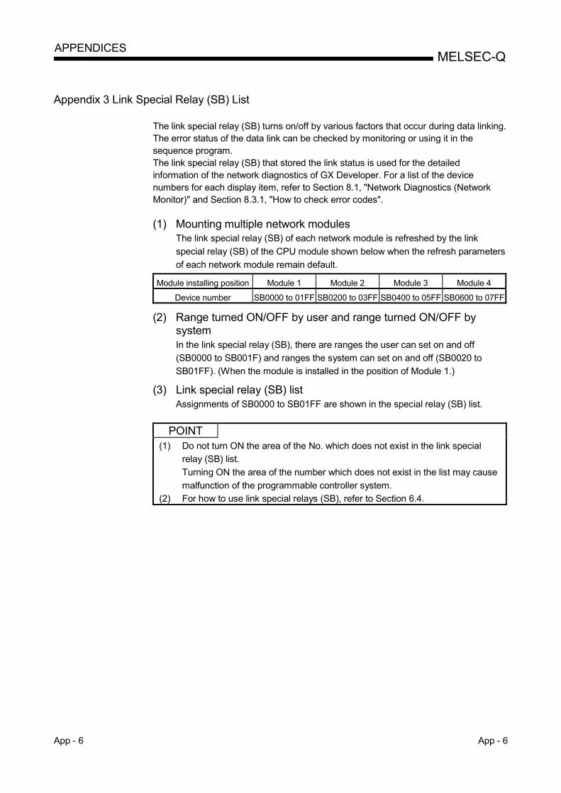
App - 6 App - 6
MELSEC-Q APPENDICES
Appendix 3 Link Special Relay (SB) List
The link special relay (SB) turns on/off by various factors that occur during data linking. The error status of the data link can be checked by monitoring or using it in the sequence program. The link special relay (SB) that stored the link status is used for the detailed information of the network diagnostics of GX Developer. For a list of the device numbers for each display item, refer to Section 8.1, "Network Diagnostics (Network Monitor)" and Section 8.3.1, "How to check error codes". (1) Mounting multiple network modules
The link special relay (SB) of each network module is refreshed by the link
special relay (SB) of the CPU module shown below when the refresh parameters
of each network module remain default.
Module installing position Module 1 Module 2 Module 3 Module 4
Device number SB0000 to 01FF SB0200 to 03FF SB0400 to 05FF SB0600 to 07FF
(2) Range turned ON/OFF by user and range turned ON/OFF by system In the link special relay (SB), there are ranges the user can set on and off
(SB0000 to SB001F) and ranges the system can set on and off (SB0020 to
SB01FF). (When the module is installed in the position of Module 1.)
(3) Link special relay (SB) list Assignments of SB0000 to SB01FF are shown in the special relay (SB) list.
POINT
(1) Do not turn ON the area of the No. which does not exist in the link special
relay (SB) list.
Turning ON the area of the number which does not exist in the list may cause
malfunction of the programmable controller system.
(2) For how to use link special relays (SB), refer to Section 6.4.

App - 7 App - 7
MELSEC-Q APPENDICES
Table 3 Link special relay (SB) list
No. Name Description
Use permitted/prohibited
Control station
Normal station
Remote master station
Remote I/O station
Loop Bus Loop Bus Loop Bus Loop Bus
1 3
SB0000
(0)
Link startup (host)
Restarts the host's cyclic transmission.
Off: Start not instructed On: Start instructed (valid at rise) 2
1 3
SB0001
(1)
Link stop (host)
Stops the host's cyclic transmission.
Off: Stop not instructed On: Stop instructed (valid at rise) 2
1 3
SB0002
(2)
System link startup
Restarts the cyclic transmission according to the contents of
SW0000 to SW0004.
Off: Start not instructed On: Start instructed (valid at rise) 2
1 3
SB0003
(3)
System link stop
Stops the cyclic transmission according to the contents of
SW0000 to SW0004.
Off: Stop not instructed On: Stop instructed (valid at rise) 2
SB0005
(5) Clear retry count
Clears the retry count (SW00C8 to SW00C9) to 0.
Off: Clear not instructed On: Clear instructed (valid when on) 2
1
SB0006
(6)
Clear communication
error count
Clears the communication error (SW00B8 to SW00C7) to 0.
Off: Clear not instructed On: Clear instructed (valid when on) 2
[Availability column] Loop: optical loop, Bus: coaxial/twisted bus
: Available, : Not available
1: Used in the network tests of GX Developer.
2: The SB0000 to SB0003 become valid when only one point turns on.
SB0000 is validAB0001 is valid
SB0001
SB0000 OFF
OFF
OFF
ON
ON
3: Valid only when the SB0047 is off. When it turns on (error), the last data are retained.

App - 8 App - 8
MELSEC-Q APPENDICES
Table 3 Link special relay (SB) list (continued)
No. Name Description
Use permitted/prohibited
Control station
Normal station
Remote master station
Remote I/O station
Loop Bus Loop Bus Loop Bus Loop Bus
SB0007 (7)
Clear forward loop transmission errors
Clears the line abnormal detection (SW00CC) of the forward loop side to 0.
Off: Clear not instructed On: Clear instructed (valid when on)
SB0008 (8)
Clear reverse loop transmission errors
Clears the line abnormal detection (SW00CD) of the reverse loop side to 0.
Off: Clear not instructed On: Clear instructed (valid when on)
6 SB0009
(9) Clear loop switch count
Clears the loop switch count (SW00CE to SW00E7) to 0. Off: Clear not instructed On: Clear instructed (valid when on)
SB000A (10)
Clear transient transmission errors
Clears the transient transmission errors (SW00EE, SW00EF) to 0.
Off: Clear not instructed On: Clear instructed (valid when on)
SB000B (11)
Transient transmission error area setting
Designates whether to overwrite or retain the transient transmission errors (SW00F0 to SW00FF).
Off: Overwrite On: Retain
3 4 SB000F
(15) Clear minor errors
Clears all of the minor errors detected by remote I/O stations. This is executed on all the remote I/O stations. While SB000F is ON, any minor error is not detected on all of the remote I/O stations. On multiplexed remote I/O networks or redundant multiplexed remote I/O networks, this can be operated only from the master station.
Off: Clear not instructed On: Clear instructed (valid when on)
SB0011 (17)
Data link operation designation
Designates the data link operation. Off: No switch instruction On: Switch instruction (valid when on)
When On is detected, data link switches from Online (normal data link) operation to Online (debug) operation, or from Online (debug) operation to Online (normal operation).
Debug operation Online operation
SB0011
Debug operation
OFF OFF
ON
OFF
ON ON
SB0014 (20)
Remote sub-master station switching command
Forcibly directs the remote sub-master station that is performing master operation to shift to sub-master operation. (It is invalid for the redundant system.)
Off: Without directive On: With directive
SB0018 (24)
System switching monitoring time setting valid flag
Indicates whether the system switching monitoring time setting (SW0018) is valid or invalid in case of a data link error.
Off: Invalid On: Valid (valid at the time of startup)
SB0020 (32)
Module status
Indicates the communication status between the network module and CPU module.
Off: Normal On: Abnormal
SB0040 (64)
Network type (host)
Indicates the network type set with the parameters of the host's network module.
Off: PLC to PLC network On: Remote I/O network
SB0041 (65)
Host station's redundant function support information
Indicates the station supports the redundant function or not. Off: Redundant function not supported On: Redundant function supported
SB0042 (66)
Power supply status of host
Indicates the external power supply status to the host's QJ71LP21S-25. (When using QJ71LP21-25, 0 is ON.)
Off: Not supplied (EXT.PW LED is OFF.) On: Supplied (EXT.PW LED is ON.)
[Availability column] Loop: optical loop, Bus: coaxial/twisted bus
: Available, : Not available 6: The SB0009 must be kept on until the SW00CE becomes "0."

App - 9 App - 9
MELSEC-Q APPENDICES
Table 3 Link special relay (SB) list (continued)
No. Name Description
Use permitted/prohibited
Control station
Normal station
Remote master station
Remote I/O station
Loop Bus Loop Bus Loop Bus Loop Bus
SB0043 (67)
Online switch (host)
Indicates the mode set by the switch of the host's network module.
Off: Online "Parameter setting mode becomes valid" On: Other than online
SB0044 (68)
Station setting (host)
When PLC to PLC network Indicates the station type set with the parameter of the host's network module.
Off: Normal station On: Control station
When remote I/O network Indicates the station type set with the parameter of the host's network module.
Off: Remote I/O station or multiplexed remote sub-master station
On: Remote master station or multiplexed remote master station
SB0045 (69)
Setting information (host)
Indicates the switch setting information (including parameter settings) of the host's network module.
Off: Normal On: Abnormal setting
SB0046 (70)
Data link operation designation result (host)
Indicates the switch setting information (including parameter settings) of the host's network module.
Off: Normal data linking On: Operating in debug mode
SB0047 (71)
Baton pass status (host)
Indicates the host's baton pass status (transient transmission enabled).
Off: Normal On: Abnormal
When an error is identified, the cause of the error can be checked in Baton pass status (host) (SW0047) and Cause of baton pass interruption (SW0048).
3 SB0048
(72)
Control station status (host)
When PLC to PLC network Indicates the host's status.
Off: Normal station On: Control station (SB0044 is on)
Sub-control station (SB0044 is off)
Remote master station status (host)
When remote I/O network Indicate the host status
Off: Remote I/O station On: SB0044=On Remote master station or multiplexed
remote master station SB0044=Off Remote I/O station or multiplexed
remote sub-master station
SB0049 (73)
Host data link status
Indicates the host's data link operation status. Off: Normal On: Abnormal
When an error is identified, the cause of the error can be checked in Cause of data link stop (SW0049).
4 SB004A
(74) Host CPU status (1)
Indicates the host's CPU status. Off: Normal On: Minor error occurred
5 SB004B
(75) Host CPU status (2)
Indicates the host's CPU status. Off: Normal On: A serious or fatal error occurred
3 SB004C
(76)
Cyclic transmission start acknowledgment status (host)
Indicates the startup acknowledgment status of the cyclic transmission.
Off: Not acknowledged (SB0000 is off) On: Start acknowledged (SB0000 is on)
3 SB004D
(77)
Cyclic transmission start completion status (host)
Indicates the completion status of the cyclic transmission. Off: Not completed (SB0000 is off) On: Start completed (SB0000 is on)
[Availability column] Loop: optical loop, Bus: coaxial/twisted bus : Available, : Not available
3: Valid only when the SB0047 is off. When it turns on (error), the last data are retained. 4: Minor errors are the type of errors that do not affect the CPU operation. 5: Serious errors are the type of errors that stop the CPU operation.
Fatal errors are also the type of errors that stop the CPU operation.

App - 10 App - 10
MELSEC-Q APPENDICES
Table 3 Link special relay (SB) list (continued)
No. Name Description
Use permitted/prohibited
Control station
Normal station
Remote master station
Remote I/O station
Loop Bus Loop Bus Loop Bus Loop Bus
3 SB004E
(78)
Cyclic transmission stop acknowledgment status (host)
Indicates the stop acknowledgment status of the cyclic transmission.
Off: Not acknowledged (SB0001 is off) On: Stop acknowledged (SB0001 is on)
3 SB004F
(79)
Cyclic transmission stop completion status (host)
Indicates the stop completion status of the cyclic transmission. Off: Not completed (SB0001 is off) On: Stop completed (SB0001 is on)
3 SB0050
(80)
Cyclic transmission start acknowledgment status (system)
Indicates the startup acknowledgment status of the cyclic transmission.
Off: Not acknowledged (SB0002 is off) On: Start acknowledged (SB0002 is on)
3 SB0051
(81)
Cyclic transmission start completion status (system)
Indicates the completion status of the cyclic transmission. Off: Not completed (SB0002 is off) On: Start completed (SB0002 is on)
3 SB0052
(82)
Cyclic transmission stop acknowledgment status (system)
Indicates the stop acknowledgment status of the cyclic transmission.
Off: Not acknowledged (SB0003 is off) On: Stop acknowledged (SB0003 is on)
3 SB0053
(83)
Cyclic transmission stop completion status (system)
Indicates the stop completion status of the cyclic transmission. Off: Not completed (SB0003 is off) On: Stop completed (SB0003 is on)
SB0054 (84)
Parameter receive status Indicates the parameter receive status.
Off: Receive completed On: Not received
SB0055 (85)
Received parameter error Indicates the status of the received parameters.
Off: Parameters normal On: Parameters abnormal
3 SB0056
(86) Communication status
Indicates the status of the transient transmission Off: Transient transmission by the control station On: Transient transmission by the sub-control station
SB0057 (87)
Parameter type Indicates the parameter type.
Off: MELSECNET/10 parameter On: MELSECNET/H parameter
SB0058 (88)
Operation designation at fault of control station
On PLC to PLC network Indicates the setting of "With data link by sub control station when control station is down."
Off: Cyclic transmission made by sub control station when control station fails.
On: Cyclic transmission not made by sub control station when control station becomes faulty
Operation designation at fault of (multiplexed) remote master station
On remote I/O network Indicates the status of designating cyclic transmission when the (multiplexed) remote master station fails.
Off: Cyclic transmission made by multiplexed remote sub-master station when multiplexed remote master station fails (multiplexed remote I/O network)
On: Cyclic transmission not made when remote master station fails (remote I/O network)
SB0059 (89)
Low-speed cyclic designation
Indicates whether or not there are any parameter settings for the low-speed cyclic transmission.
Off: No settings On: Settings exist
SB005A (90)
Parameter type 2 Indicates the parameter type of the control station.
Off: MELSECNET/10 mode, MELSECNET/H mode On: MELSECNET/H Extended mode
SB005B (91)
END asynchronous settings
Indicates the END asynchronous settings status of the remote I/O network.
Off: END asynchronous settings disabled On: END asynchronous settings enabled
SB005C (92)
I/O master station (Block 1)
Indicates the I/O master station setting (Common parameter setting) of block 1. (Valid when SB0049 is OFF)
Off: No setting On: Setting exists. (Station No. is stored in SW005C.)
[Availability column] Loop: optical loop, Bus: coaxial/twisted bus
: Available, : Not available
3: Valid only when the SB0047 is off. When it turns on (error), the last data are retained.

App - 11 App - 11
MELSEC-Q APPENDICES
Table 3 Link special relay (SB) list (continued)
No. Name Description
Use permitted/prohibited
Control station
Normal station
Remote master station
Remote I/O station
Loop Bus Loop Bus Loop Bus Loop Bus
SB005D (93)
I/O master station (Block 2)
Indicates the I/O master station setting (Common parameter setting) of block 2. (Valid when SB0049 is OFF)
Off: No setting On: Setting exists. (Station No. is stored in SW005D.)
SB0064 (100)
Reserved station designation
Indicates whether or not the station is reserved. (Valid when the SB0049 is off.)
Off: No reserved station On: Reserved station exists
If a reserved station is found, the status of each station can be checked by Reserved station designation (SW0064 to SW0067). Depending on the timing of the link refresh, Reserved station designation (SW0064 to SW0067) and the update may be offset by one sequence scan.
SB0068 (104)
Communication mode
Indicates the link scan mode (status of supplementary settings of the common parameters). (Valid when the SB0049 is off.)
Off: Normal mode On: Constant link scan mode
SB0069 (105)
Multiplex transmission designation
Indicates the transmission designation status (status of supplementary settings of the common parameters). (Valid when the SB0049 is off.)
Off: Normal transmission designation On: Multiplex transmission designation
3 SB006A
(106)
Multiplex transmission status
Indicates the transmission status. Off: Normal transmission On: Multiplex transmission
In the case of multiplex transmission, the status of each station can be checked in Multiplex transmission status (1) (SW00B0 to SW00B3) and (2) (SW00B4 to SW00B7).
3 SB006B
(107)
Multiplex remote function designation
Indicates the status of designating the multiplex remote function. Off: Not designated. On: Designated.
3 SB0070
(112)
Baton pass status of each station
Indicates the baton pass status of each station. (Not applicable to reserved stations and the station with the maximum station number or higher)
Off: All stations normal On: Faulty station exists
When any faulty station exists, each station status can be checked in Baton pass status of each station (SW0070 to SW0073). Depending on the timing of the link refresh, Baton pass status of each station (SW0070 to SW0073) and the update may be offset by one sequence scan.
3 SB0071
(113)
Baton pass status of the remote master station
Indicates the baton pass status of the master station. (Including when there is an online loop test.)
Off: Master station baton pass normal. On: Master station baton pass error.
3 SB0072
(114)
Remote sub-master station transient transmission status
Indicates the transient transmission status of the remote sub-master station.
Off: Normal On: Abnormal
3 SB0074
(116)
Cyclic transmission status of each station
Indicates the cyclic transmission status of each station. (Not applicable to reserved stations and the station with the maximum station number or higher)
Off: All stations are executing data linking On: Stations that are not executing data linking exist
When any non-executing station exists, each station status can be checked in Cyclic transmission status of each station (SW0074 to SW0077). Depending on the timing of the link refresh, Cyclic transmission status of each station (SW0074 to SW0077) and the update may be offset by one sequence scan.
[Availability column] Loop: optical loop, Bus: coaxial/twisted bus
: Available, : Not available
3: Valid only when the SB0047 is off. When it turns on (error), the last data are retained.

App - 12 App - 12
MELSEC-Q APPENDICES
Table 3 Link special relay (SB) list (continued)
No. Name Description
Use permitted/prohibited
Control station
Normal station
Remote master station
Remote I/O station
Loop Bus Loop Bus Loop Bus Loop Bus
3 SB0075
(117)
Cyclic transmission status of the remote master station
Indicates the master station cyclic transmission status. (Includes online loop test.)
Off: Master station cyclic transmission normal. On: Master station cyclic transmission error.
3 SB0076
(118)
Remote sub-master station cyclic transmission status
Indicates the cyclic transmission status of the remote sub-master station. (Including the status at an online loop test)
Off: Cyclic transmission normal On: Cyclic transmission abnormal
3 SB0077
(119)
Remote master station cyclic transmission control status
Indicates the station type that is controlling cyclic transmission at the remote I/O stations.
Off: Remote master station On: Remote sub-master station
3 SB0078
(120)
Parameter communication status of each station
Indicates the parameter transmission status of each station. (Not applicable to reserved stations and the station with the maximum station number or higher)
Off: Executing communication other than parameter communication
On: Executing parameter communication Stations that are communicating parameters can be checked in Parameter communication status of each station (SW0078 to SW007B). Depending on the timing of the link refresh, Parameter communication status of each station (SW0078 to SW007B) and the update may be offset by one sequence scan.
3
SB007A
(122)
Low-speed cyclic
communication status
Indicates the low-speed cycle communication status.
It is indicated to have transmitted by turning the bit on for either
the SB007A or SB007B.
SB007A
SB007BCycle interval
OFF OFF
ON ON
OFF OFF
ON
OFF
ON
3
SB007B
(123)
3
SB007C
(124)
Parameter status of each
station
Indicates the parameter status of each station. (Not applicable to
reserved stations and the station with the maximum station
number and higher)
Off: No station detected parameter errors
On: A station detected parameter errors
Stations that have parameter errors can be checked in
Parameter error status of each station (SW007C to SW007F).
Depending on the timing of the link refresh, Parameter error
status of each station (SW007C to SW007F) and the update may
be offset by one sequence scan.
[Availability column] Loop: optical loop, Bus: coaxial/twisted bus
: Available, : Not available
3: Valid only when the SB0047 is off. When it turns on (error), the last data are retained.

App - 13 App - 13
MELSEC-Q APPENDICES
Table 3 Link special relay (SB) list (continued)
No. Name Description
Use permitted/prohibited
Control station
Normal station
Remote master station
Remote I/O station
Loop Bus Loop Bus Loop Bus Loop Bus
3 5
SB0080
(128)
CPU operation status of
each station (1)
On PLC to PLC network
Indicates the CPU operating status of each station (including the
own station).
Off: All stations normal
On: A moderate or serous error identified
If a moderate or serious error is identified, the status of each
station can be checked in CPU operation status of each station
(1) (SW0080 to SW0083).
Depending on the timing of the link refresh, CPU operation status
of each station (1) (SW0080 to SW0083) and the update may be
offset by one sequence scan.
On remote I/O network
Indicates the operating status of each remote I/O station
(including the own station).
Off: All stations normal
On: Faulty station exists
If any faulty station exists, the status of each station can be
checked in CPU operation status of each station (1) (SW0080 to
SW0083).
Depending on the timing of the link refresh, CPU operation status
of each station (1) (SW0080 to SW0083) and the update may be
offset by one sequence scan.
3
SB0084
(132)
CPU RUN status of each
station
Indicates the CPU RUN status of each station.
Off: All stations are in the RUN or STEP RUN status
On: Stations in the STOP or PAUSE status exist
(including the host)
When some stations are in the STOP or PAUSE status, each
station status can be checked in CPU RUN status of each station
(SW0084 to SW0087).
Depending on the timing of the link refresh, CPU RUN status of
each station (SW0084 to SW0087) and the update may be offset
by one sequence scan.
3
SB0085
(133)
CPU RUN status of the
remote master station
Indicates the CPU run status of remote master station.
Off: Run or STEP RUN status
On: STOP or PAUSE status
3
SB0086
(134)
Remote sub-master
station CPU RUN status
Indicates the CPU status of the multiplexed remote sub-master
station.
Off: RUN or STEP RUN status
On: STOP or PAUSE status
3 4
SB0088
(136)
CPU operation status of
each station (2)
Indicates the operation status of each station's CPU or of each
remote I/O station (including the host station).
Off: All stations normal
On: Stations with minor errors exist
If any station with a minor error exists, the status of each station
can be checked in CPU operation status of each station (2)
(SW0088 to SW008B).
Depending on the timing of the link refresh, CPU operation status
of each station (2) (SW0088 to SW008B) and the update may be
offset by one sequence scan.
[Availability column] Loop: optical loop, Bus: coaxial/twisted bus
: Available, : Not available
3: Valid only when the SB0047 is off. When it turns on (error), the last data are retained.
4: Minor errors are the type of errors that do not affect the CPU operation.
5: Serious errors are the type of errors that stop the CPU operation.
Fatal errors are also the type of errors that stop the CPU operation.
7: Available only in the remote sub-master station.

App - 14 App - 14
MELSEC-Q APPENDICES
Table 3 Link special relay (SB) list (continued)
No. Name Description
Use permitted/prohibited
Control station
Normal station
Remote master station
Remote I/O station
Loop Bus Loop Bus Loop Bus Loop Bus
3
SB008C
(140)
External power supply
information
Indicates the information of the external power supply (including
the host).
Off: All stations are without external power supply
On: Stations with external power supply exist
When any station with external power supply exists, the status of
each station can be checked in Power supply status of each
station (SW008C to SW008F).
Depending on the timing of the link refresh, Power supply status
of each station (SW008C to SW008F) and the update may be
offset by one sequence scan.
3
SB008D
(141)
Module type of each
station
Indicates the module type of each station.
Off: All stations are NET/10 type modules
On: NET/10H type modules exist
SB0090
(144) Host loop status
Indicates the host's loop status.
Off: Normal
On: Abnormal
When an error is identified, the error details can be checked by
Loopback information (SW0090).
3
SB0091
(145)
Forward loop status
Indicates the status of stations connected to the forward loop.
Off: All stations normal
On: Faulty station exists
When any faulty station exists, the status of each station can be
checked in Forward loop status of each station (SW0091 to
SW0094).
Depending on the timing of the link refresh, Forward loop status
of each station (SW0091 to SW0094) and the update may be
offset by one sequence scan.
3
SB0092
(146)
Forward loop status of
remote master station
Indicates the forward loop status of the remote master station.
Off: Normal
On: Error
7
3
SB0095
(149)
Reverse loop status
Indicates the status of stations connected to the reverse loop.
Off: All stations normal
On: Faulty station exists
When any faulty station exists, the status of each station can be
checked in Reverse loop status of each station (SW0095 to
SW0098).
Depending on the timing of the link refresh, Reverse loop status
of each station (SW0095 to SW0098) and the update may be
offset by one sequence scan.
3
SB0096
(150)
Reverse loop status of
remote master station
Indicates the reverse loop status of the remote master station.
Off: Normal
On: Error
3
SB0099
(153)
Forward loop loopback
Indicates the loopback status of the forward loop while the
system is operating.
Off: Not executed
On: Executing stations exist
(Executing stations are stored in the SW0099)
3
SB009A
(154)
Reverse loop loopback
Indicates the loopback status of the reverse loop while the
system is operating.
Off: Not executed
On: Executing stations exist
(Executing stations are stored in the SW009A)
[Availability column] Loop: optical loop, Bus: coaxial/twisted bus
: Available, : Not available
3: Valid only when the SB0047 is off. When it turns on (error), the last data are retained.
7: Available only in the remote sub-master station.
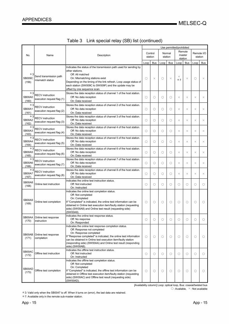
App - 15 App - 15
MELSEC-Q APPENDICES
Table 3 Link special relay (SB) list (continued)
No. Name Description
Use permitted/prohibited
Control station
Normal station
Remote master station
Remote I/O station
Loop Bus Loop Bus Loop Bus Loop Bus
3
SB009C
(156)
Send transmission path
mismatch status
Indicates the status of the transmission path used for sending by other stations.
Off: All matched On: Mismatching stations exist
Depending on the timing of the link refresh, Loop usage status of each station (SW009C to SW009F) and the update may be offset by one sequence scan.
7
3
SB00A0
(160)
RECV instruction
execution request flag (1)
Stores the data reception status of channel 1 of the host station.
Off: No data reception
On: Data received
3
SB00A1
(161)
RECV instruction
execution request flag (2)
Stores the data reception status of channel 2 of the host station.
Off: No data reception
On: Data received
3 SB00A2
(162)
RECV instruction execution request flag (3)
Stores the data reception status of channel 3 of the host station. Off: No data reception On: Data received
3 SB00A3
(163)
RECV instruction execution request flag (4)
Stores the data reception status of channel 4 of the host station. Off: No data reception On: Data received
3 SB00A4
(164)
RECV instruction execution request flag (5)
Stores the data reception status of channel 5 of the host station. Off: No data reception On: Data received
3 SB00A5
(165)
RECV instruction execution request flag (6)
Stores the data reception status of channel 6 of the host station. Off: No data reception On: Data received
3 SB00A6
(166)
RECV instruction execution request flag (7)
Stores the data reception status of channel 7 of the host station. Off: No data reception On: Data received
3 SB00A7
(167)
RECV instruction execution request flag (8)
Stores the data reception status of channel 8 of the host station. Off: No data reception On: Data received
SB00A8 (168)
Online test instruction Indicates the online test instruction status.
Off: Not instructed On: Instructed
SB00A9 (169)
Online test completion
Indicates the online test completion status. Off: Not completed On: Completed
If "Completed" is indicated, the online test information can be obtained in Online test execution item/faulty station (requesting side) (SW00A8) and Online test result (requesting side) (SW00A9).
SB00AA (170)
Online test response instruction
Indicates the online test response status. Off: No response On: Responded
SB00AB (171)
Online test response completion
Indicates the online test response completion status. Off: Response not completed On: Response completed
If "Response completed" is indicated, the online test information can be obtained in Online test execution item/faulty station (responding side) (SW00AA) and Online test result (responding side) (SW00AB).
SB00AC (172)
Offline test instruction Indicates the offline test instruction status.
Off: Not instructed On: Instructed
SB00AD (173)
Offline test completion
Indicates the offline test completion status. Off: Not completed On: Completed
If "Completed" is indicated, the offline test information can be obtained in Offline test execution item/faulty station (requesting side) (SW00AC) and Offline test result (requesting side) (SW00AD).
[Availability column] Loop: optical loop, Bus: coaxial/twisted bus : Available, : Not available
3: Valid only when the SB0047 is off. When it turns on (error), the last data are retained.
7: Available only in the remote sub-master station.

App - 16 App - 16
MELSEC-Q APPENDICES
Table 3 Link special relay (SB) list (continued)
No. Name Description
Use permitted/prohibited
Control station
Normal station
Remote master station
Remote I/O station
Loop Bus Loop Bus Loop Bus Loop Bus
SB00AE (174)
Offline test response Indicates the response status for offline test.
Off: No response On: Response
SB00AF (175)
Offline test response completion
Indicates the response status for offline test end. Off: Response not completed On: Response completed
If "Response completed" is indicated, the offline test information can be obtained in Offline test execution item (responding side) (SW00AE) and Offline test result (responding side) (SW00AF).
SB00EE (238)
Transient error Indicates the transient transmission error status.
Off: No error On: Errors exist
3 SB01C4
(452)
Remote sub-master station switching acceptance status
Indicates the status of accepting the directive to shift from master operation to sub-master operation.
Off: Without acceptance On: With acceptance
3 SB01C5
(453)
Remote sub-master station switching status
Indicates the operation status of a shift from master operation to sub-master operation.
Off: Without shift On: Shift completion
3 SB01C8
(456)
Send/receive device number valid/invalid status
Indicates whether the send/receive device numbers (SW01C8 to SW01CF) of the remote master station or remote sub-master station are valid or invalid.
Off: Invalid On: Valid
3 SB01E0
(480)
Network type consistency check
Indicates whether there is a mismatch between the network types of the control station and normal stations on the network. • When the control station is in the MELSECNET/H Extended
mode Off: All normal stations are set to the MELSECNET/H
Extended mode. On: There is a normal station set to the MELSECNET/H
mode or MELSECNET/10 mode. • When the control station is in the MELSECNET/H mode or
MELSECNET/10 mode Off: All normal stations are set to the MELSECNET/H mode
or MELSECNET/10 mode. On: There is a normal station set to the MELSECNET/H
Extended mode. When a mismatch is found, the status of each station can be checked by Network type consistency check (SW01E0 to SW01E3). Depending on the timing of the link refresh, Network type consistency check (SW01E0 to SW01E3) and the update may be offset by one sequence scan.
[Availability column] Loop: optical loop, Bus: coaxial/twisted bus
: Available, : Not available 3: Valid only when the SB0047 is off. When it turns on (error), the last data are retained.

App - 17 App - 17
MELSEC-Q APPENDICES
Table 3 Link special relay (SB) list (continued)
No. Name Description
Use permitted/prohibited
Control station
Normal station
Remote master station
Remote I/O station
Loop Bus Loop Bus Loop Bus Loop Bus
3 SB01F4
(500)
Redundant system status (1)
Indicates the operation mode of each station's CPU. Off: CPUs of all stations in backup mode On: Separate mode
(excluding reserved stations and stations of the number exceeding the maximum) This relay turns off when all of SW01F4 to SW01F7 are "0." In the separate mode, the status of each station can be checked by Redundant system status (1) (SW01F4 to SW01F7). Depending on the timing of the link refresh, Redundant system status (1) (SW01F4 to SW01F7) and the update may be offset by one sequence scan.
3 SB01F8
(504)
Redundant system status (2)
Indicates the pairing setting status of each station. Off: No pairing setting On: Pairing set station exists
(excluding stations after the maximum station number ) This relay turns off when all of SW01F8 to SW01FB are "0." When a pairing set station exists, the status of each station can be checked by Redundant system status (2) (SW01F8 to SW01FB). Depending on the timing of the link refresh, Redundant system status (2) (SW01F8 to SW01FB) and the update may be offset by one sequence scan.
3 SB01FC
(508)
Redundant system status (3)
Indicates the operation status of each station's CPU (control system/standby system).
Off: Control system CPUs on all stations On: Standby system CPU exists
(excluding reserved stations and stations after the maximum station number) This relay turns off when all of SW01FC to SW01FF are "0." When a standby system CPU exists, the status of each station can be checked by Redundant system status (3) (SW01FC to SW01FF). Depending on the timing of the link refresh, Redundant system status (3) (SW01FC to SW01FF) and the update may be offset by one sequence scan.
[Availability column] Loop: optical loop, Bus: coaxial/twisted bus
: Available, : Not available 3: Valid only when the SB0047 is off. When it turns on (error), the last data are retained.

App - 18 App - 18
MELSEC-Q APPENDICES
Appendix 4 Link Special Register (SW) List
In the link special register (SW), the data linking information is stored as numeric values. Thus, faulty areas and causes of errors can be checked using or monitoring the link special registers in the sequence programs. Moreover, the link special register (SW) that stores the link status is used for the detailed information of the network diagnostics of GX Developer. For a list of the device numbers for each display item, refer to Section 8.1, "Network Diagnostics (Network Monitor)" and Section 8.3.1, "How to check error codes". (1) Mounting multiple network modules
The link special register (SW) of each network module is refreshed by the link
special register (SW) of the CPU module shown below when the refresh
parameters of each network module remain default.
Module installing position Module 1 Module 2 Module 3 Module 4
Device number SW0000 to 01FF SW0200 to 03FF SW0400 to 05FF SW0600 to 07FF
(2) Range turned ON/OFF by user and range turned ON/OFF by system The link special register (SW) has the user setting area range (SW0000 to
SW001F) and the system setting area range (SW0020 to SW01FF). (When the
module is installed in the position of Module 1)
(3) Link special register (SW) list Assignments of SW0000 to SW01FF are shown in the special register (SW) list.
POINT
(1) Do not write data to the area of the No. which does not exist in the link special
register (SW) list.
Writing data to the area of the No. which does not exist in the list may cause
malfunction of the programmable controller system.
(2) For how to use link special register (SW), refer to Section 6.4.

App - 19 App - 19
MELSEC-Q APPENDICES
Table 4 Link special register (SW) list
No. Name Description
Use permitted/prohibited
Control station
Normal station
Remote master station
Remote I/O station
Loop Bus Loop Bus Loop Bus Loop Bus
1
SW0000
(0)
Link stop/startup direction
content
Sets the station that stops/restarts data linking.
00H: Host
01H: All stations
02H: Designated station
80H: Host (forced stop/restart)
81H: All stations (forced stop /restart)
82H: Designated station (forced stop /restart)
1
SW0001
(1)/
SW0002
(2)/
SW0003
(3)/
SW0004
(4)
Sets whether the designated station executes data linking.
(When the SW0000 is 02H or 82H.)
Sets the bits to 1 for stations whose data linking is
stopped/restarted.
0: Invalid data linking stop/restart instruction
1: Valid data linking stop/restart instruction
16
32
48
64
15 14 13 5 4 3 2 1
31 30
47 46
63 62
29
45
61
21 20 19 18 17
37 36 35 34 33
53 52 51 50 49
to
to
to
to
b15 b14 b13 b12 b4 b3 b2 b1 b0
SW0001
SW0002
SW0003
SW0004
The numbers 1 to 64 in the above table indicate the station numbers.
to
SW0008
(8)
Logical channel setting
(channel 1)
Sets the logical channel number for physical channel number 1.
(Valid only for channels on the receiving side) 0 : Logical channel number 1 (default)
1 to 64 : Other logical channel number is set.
SW0009
(9)
Logical channel setting
(channel 2)
Sets the logical channel number for physical channel number 2.
(Valid only for channels on the receiving side) 0 : Logical channel number 2 (default)
1 to 64 : Other logical channel number is set.
SW000A
(10)
Logical channel setting
(channel 3)
Sets the logical channel number for physical channel number 3.
(Valid only for channels on the receiving side) 0 : Logical channel number 3 (default)
1 to 64 : Other logical channel number is set.
SW000B
(11) Logical channel setting
(channel 4)
Sets the logical channel number for physical channel number 4.
(Valid only for channels on the receiving side) 0 : Logical channel number 4 (default)
1 to 64 : Other logical channel number is set.
SW000C
(12) Logical channel setting
(channel 5)
Sets the logical channel number for physical channel number 5.
(Valid only for channels on the receiving side) 0 : Logical channel number 5 (default)
1 to 64 : Other logical channel number is set.
SW000D
(13) Logical channel setting
(channel 6)
Sets the logical channel number for physical channel number 6.
(Valid only for channels on the receiving side) 0 : Logical channel number 6 (default)
1 to 64 : Other logical channel number is set.
SW000E (14)
Logical channel setting (channel 7)
Sets the logical channel number for physical channel number 7. (Valid only for channels on the receiving side)
0 : Logical channel number 7 (default)
1 to 64 : Other logical channel number is set.
SW000F (15)
Logical channel setting (channel 8)
Sets the logical channel number for physical channel number 8. (Valid only for channels on the receiving side)
0 : Logical channel number 8 (default)
1 to 64 : Other logical channel number is set.
[Availability column] Loop: optical loop, Bus: coaxial/twisted bus
: Available, : Not available
1: Used in the network test of GX Developer.

App - 20 App - 20
MELSEC-Q APPENDICES
Table 4 Link special register (SW) list (continued)
No. Name Description
Use permitted/prohibited
Control station
Normal station
Remote master station
Remote I/O station
Loop Bus Loop Bus Loop Bus Loop Bus
SW0018 (24)
System switching monitoring time setting
Set the time from the occurrence of a data link error to the recognition of data link stop in the redundant system.
0 : 2 seconds (default)
1 to 500 : Units of 10 ms (Units of 10 ms for 10 ms to 5
seconds)
2
SW001C
(28)
Number of retries
Indicates the change of the number of retries for the time of the issue of a request in send and receive instructions.
0 : 7 times (default)
1 to 7 : Setting exists
2
SW001D
(29)
Retry interval
Indicates the change of the retry interval for the time of the issue of a request in send and receive instructions.
0 : 100 ms (default)
1 to FEH : Setting exists (unit: ms)
2
SW001E
(30)
Number of gates
Indicates the change of the number of gates for the time of the issue of a request in send and receive instructions.
0 : 7 (default)
1 to EFH : Setting exists
SW0020 (32)
Module status
Stores the communication status between the network module and CPU module.
0 : Normal
Other than 0 : Stored an error code. (Refer to the user's manual for the CPU module used.)
SW0031 (49)
ZNRD instruction processing result
Indicates the processing result of the ZNRD instruction.
0 : Normal completion
Other than 0 : Abnormal completion (Refer to the error codes in Section 8.3)
Send/receive instruction (1) processing result
Indicates the processing results of the SEND/RECV/READ/ WRITE/REQ/RECVS/RRUN/RSTOP/RTMRD/RTMWR/REMFR/REMTO instructions (when physical channel 1 is used).
0 : Normal completion
Other than 0 : Abnormal completion (Refer to the error codes in Section 8.3)
SW0033 (51)
ZNWR instruction processing result
Indicates the processing result of the ZNWR instruction.
0 : Normal completion
Other than 0 : Abnormal completion (Refer to the error codes in Section 8.3)
Send/receive instruction (2) processing result
Indicates the processing results of the SEND/RECV/READ/ WRITE/REQ/RECVS/RRUN/RSTOP/RTMRD/RTMWR/REMFR/REMTO instructions (when physical channel 2 is used).
0 : Normal completion
Other than 0 : Abnormal completion (Refer to the error codes in Section 8.3)
SW0035 (53)
Send/receive instruction (3) processing result
Indicates the processing results of the SEND/RECV/READ/ WRITE/REQ/RECVS/RRUN/RSTOP/RTMRD/RTMWR/REMFR/REMTO instructions (when physical channel 3 is used).
0 : Normal completion
Other than 0 : Abnormal completion (Refer to the error codes in Section 8.3)
SW0037 (55)
Send/receive instruction (4) processing result
Indicates the processing results of the SEND/RECV/READ/WRITE/ REQ/RECVS/RRUN/RSTOP/RTMRD/RTMWR/REMFR/REMTO instructions (when physical channel 4 is used).
0 : Normal completion
Other than 0 : Abnormal completion (Refer to the error codes in Section 8.3)
[Availability column] Loop: optical loop, Bus: coaxial/twisted bus
: Available, : Not available
2: Valid only when the SB0047 is off. When it turns on (error), the last data are retained.
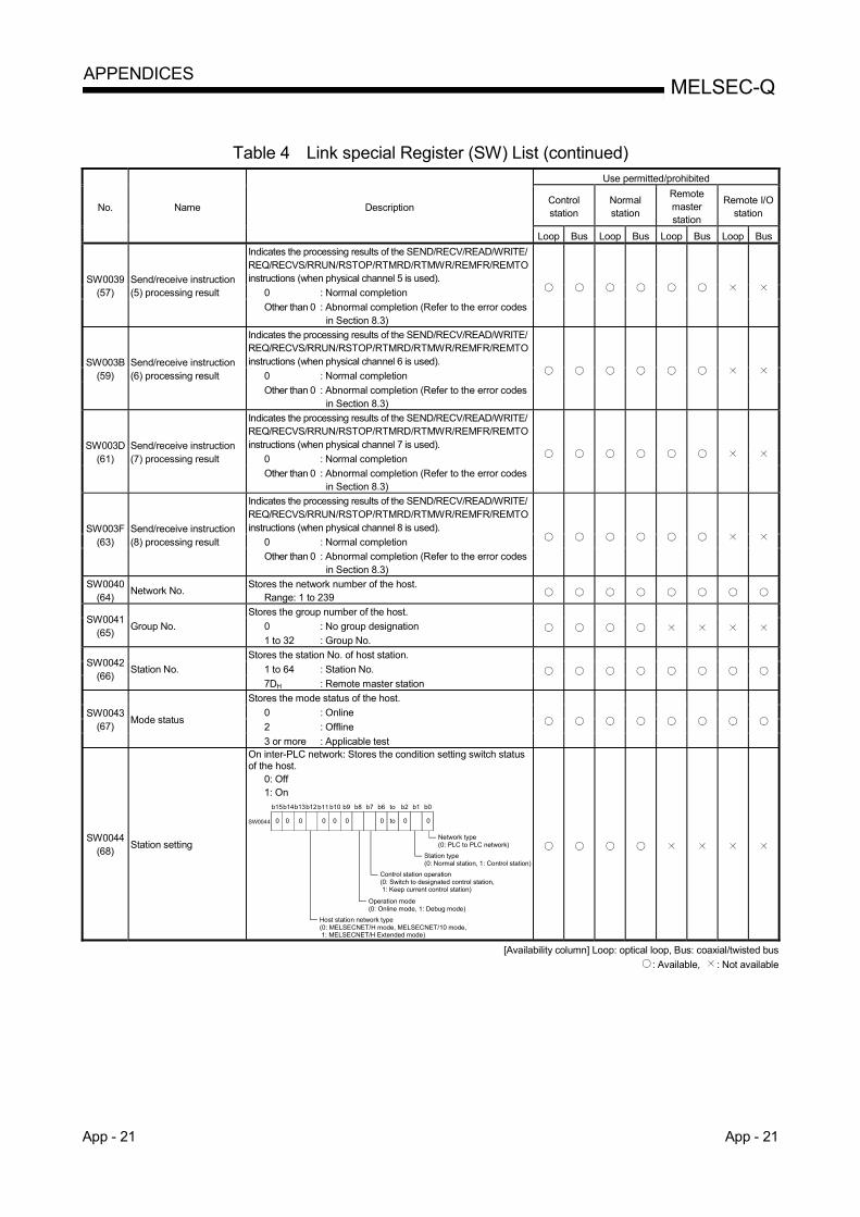
App - 21 App - 21
MELSEC-Q APPENDICES
Table 4 Link special Register (SW) List (continued)
No. Name Description
Use permitted/prohibited
Control station
Normal station
Remote master station
Remote I/O station
Loop Bus Loop Bus Loop Bus Loop Bus
SW0039 (57)
Send/receive instruction (5) processing result
Indicates the processing results of the SEND/RECV/READ/WRITE/ REQ/RECVS/RRUN/RSTOP/RTMRD/RTMWR/REMFR/REMTO instructions (when physical channel 5 is used).
0 : Normal completion
Other than 0 : Abnormal completion (Refer to the error codes in Section 8.3)
SW003B (59)
Send/receive instruction (6) processing result
Indicates the processing results of the SEND/RECV/READ/WRITE/ REQ/RECVS/RRUN/RSTOP/RTMRD/RTMWR/REMFR/REMTO instructions (when physical channel 6 is used).
0 : Normal completion
Other than 0 : Abnormal completion (Refer to the error codes in Section 8.3)
SW003D (61)
Send/receive instruction (7) processing result
Indicates the processing results of the SEND/RECV/READ/WRITE/ REQ/RECVS/RRUN/RSTOP/RTMRD/RTMWR/REMFR/REMTO instructions (when physical channel 7 is used).
0 : Normal completion
Other than 0 : Abnormal completion (Refer to the error codes in Section 8.3)
SW003F (63)
Send/receive instruction (8) processing result
Indicates the processing results of the SEND/RECV/READ/WRITE/ REQ/RECVS/RRUN/RSTOP/RTMRD/RTMWR/REMFR/REMTO instructions (when physical channel 8 is used).
0 : Normal completion
Other than 0 : Abnormal completion (Refer to the error codes in Section 8.3)
SW0040 (64)
Network No. Stores the network number of the host.
Range: 1 to 239
SW0041 (65)
Group No.
Stores the group number of the host.
0 : No group designation
1 to 32 : Group No.
SW0042 (66)
Station No.
Stores the station No. of host station.
1 to 64 : Station No.
7DH : Remote master station
SW0043 (67)
Mode status
Stores the mode status of the host.
0 : Online
2 : Offline
3 or more : Applicable test
SW0044 (68)
Station setting
On inter-PLC network: Stores the condition setting switch status of the host.
0: Off 1: On
SW0044 0 0 0 0
b0b1b2tob6b7b8b9b10b11b12b13b15b14
0 to 0000
Network type(0: PLC to PLC network)
Station type(0: Normal station, 1: Control station)
Control station operation(0: Switch to designated control station, 1: Keep current control station)
Operation mode(0: Online mode, 1: Debug mode)
Host station network type(0: MELSECNET/H mode, MELSECNET/10 mode, 1: MELSECNET/H Extended mode)
[Availability column] Loop: optical loop, Bus: coaxial/twisted bus
: Available, : Not available
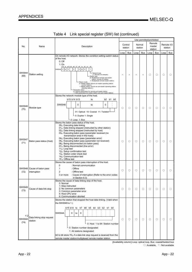
App - 22 App - 22
MELSEC-Q APPENDICES
Table 4 Link special register (SW) list (continued)
No. Name Description
Use permitted/prohibited
Control station
Normal station
Remote master station
Remote I/O station
Loop Bus Loop Bus Loop Bus Loop Bus
SW0044 (68)
Station setting
On remote I/O network: Stores the condition setting switch status of the host.
0: Off 1: On
0 0 0 1SW0044
b15 b8 b7 b6 b2 b1 b0
0
b9
0
b10to
to
to
to
Network type(1: Remote I/O network)
Station type(0: Multiplexed remote sub-master station, remote I/O station 1: Multiplexed remote master station)
Return mode(0: Master station returns as master operating station (control station). 1: Master station returns as sub-master operating station (standby station).)
Parameter status(0: Without parameters for remote sub-master station 1: With parameters for master station and sub-master station)
SW0046 (70)
Module type
Stores the network module type of the host.
0 0SW0046
b15 b14 b13 to b2 b1 b0
to
0: Duplex 1: Single
01: Optical 10: Coaxial 11: Twisted
0: Loop 1: Bus
SW0047
(71) Baton pass status (host)
Stores the baton pass status of the host. 00H: Executing data linking 01H: Data linking stopped (instructed by other station) 02H: Data linking stopped (instructed by host) 03H: Executing baton pass (parameter received (no
transmission area in the host)) 04H: Executing baton pass (parameter error) 05H: Executing baton pass (parameter not received) 06H: Being disconnected (no baton pass) 07H: Being disconnected (line error) 11H: Loop test 12H: Setup confirmation test 13H: Station order check test 14H: Communication test 1FH: Offline test
SW0048
(72)
Cause of baton pass
interruption
Stores the cause of baton pass interruption of the host.
0 : Normal communication 1 : Offline 2 : Offline test 3 or more : Cause of interruption (Refer to the error codes
in Section 8.3)
SW0049
(73) Cause of data link stop
Stores the cause of data linking stop of the host. 0: Normal 1: Stop instructed 2: No common parameters 3: Common parameter error 4: Host CPU error 6: Communication aborted
2
SW004A
(74)
Data linking stop request
station
Stores the station that stopped the host data linking. (Valid when
the SW0049 is 1.)
toSW004A
0: Host 1 to 64: Station number
b15 b14 to b2 b1 b0
0: Station number designated
1: All stations designated
b7 b6 b5 b4 b3
0 0
b0 to b6 store 7DH if a data link stop request is received from the
remote master station/multiplexed remote master station.
[Availability column] Loop: optical loop, Bus: coaxial/twisted bus
: Available, : Not available

App - 23 App - 23
MELSEC-Q APPENDICES
Table 4 Link special register (SW) list (continued)
No. Name Description
Use permitted/prohibited
Control station
Normal station
Remote master station
Remote I/O station
Loop Bus Loop Bus Loop Bus Loop Bus
2
SW004B
(75)
Host CPU status
Indicates the CPU status of the host.
0 : Normal
Other than 0 : Abnormal (For the error codes, refer to
Section 8.3 or the "Error Code" chapter of
QCPU User's Manual (Hardware Design,
Maintenance and Inspection).)
2
SW004D
(77)
Data linking start status
(host)
Stores the result of starting cyclic transmission with Link startup
(host) (SB0000).
0 : Normal
Other than 0 : Abnormal (Refer to the error codes in Section
8.3)
2
SW004F
(79)
Data linking stop status
(host)
Stores the result of stopping cyclic transmission with Link stop
(host) (SB0001).
0 : Normal
Other than 0 : Abnormal (Refer to the error codes in Section
8.3)
2
SW0051
(81)
Data linking start status
(entire system)
Stores the result of starting cyclic transmission with System link
startup (SB0002).
0 : Normal
Other than 0 : Abnormal (Refer to the error codes in Section
8.3)
2 SW0053
(83)
Data linking stop status (entire system)
Stores the result of stopping cyclic transmission with System link stop (SB0003).
0 : Normal
Other than 0 : Abnormal (Refer to the error codes in Section 8.3)
SW0054 (84)
Parameter information
At the PLC to PLC network. Stores the parameter information. (When the SB0054 and SB0055 are off.)
0 0
b15 b14 to b2 b1 b0
to
MELSECNET/H0: Not designated1: Designated
Type00: Use only common parameters01: Common parameters + station specific parameters10: Use only default parameters11: Default parameters + station specific parameters
(When the SB0055 is on.)
0
b15 b2 b1 b0
to
b3b4
10 1 1 1 = 0FH: Parameter error
Check the error code in the SW055.
0
When remote I/O net Stores the parameter information. (When the SB0054 and SB0055 are off.)
0
b15 b2 b1 b0b3
0 0 0
Intelligent function module parameter0: No1: Yes
to
to
SW0055 (85)
Parameter setting status
At the PLC to PLC network. Stores the status of the parameters.
0 : Normal parameter
1 or more : Abnormal parameter (Refer to the error codes in Section 8.3)
[Availability column] Loop: optical loop, Bus: coaxial/twisted bus
: Available, : Not available
2: Valid only when the SB0047 is off. When it turns on (error), the last data are retained.

App - 24 App - 24
MELSEC-Q APPENDICES
Table 4 Link special register (SW) list (continued)
No. Name Description
Use permitted/prohibited
Control station
Normal station
Remote master station
Remote I/O station
Loop Bus Loop Bus Loop Bus Loop Bus
2 SW0056
(86)
Current control station
At the PLC to PLC network. Stores the number of the station that actually operates as the control station (including a sub-control station).
Range: 1 to 64
Current remote master station
When remote I/O network Stores the station number controlling the current baton pass.
7DH : Remote master station or multiplexed remote master station
1 to 64 : Multiplexed remote sub-master station
SW0057 (87)
Designated control station At the PLC to PLC network. Stores the number of the station that is set as the control station.
Range: 1 to 64 0: Designated control station error
Designated remote master station
When remote I/O network.
7DH : Remote master station
Other than 7DH : Remote master station error.
SW0059 (89)
Total number of link stations
Stores the total number of link stations that is set with the parameters.
Range: 1 to 64 (64 when there is no parameter.)
2 SW005A
(90)
Maximum baton pass station
Stores the maximum station number among the stations executing the baton pass.
Range: 1 to 64
2 SW005B
(91)
Maximum cyclic transmission station
Stores the maximum station number among the stations executing the cyclic transmission.
Range: 1 to 64
SW005C (92)
I/O master station (block 1)
Stores the station number of the I/O master station of block 1 with PLC to PLC network.
0 : None
1 to 64 : Station number
Valid when the SB0049 is off.
SW005D (93)
I/O master station (block 2)
Stores the station number of the I/O master station of block 2 with PLC to PLC network.
0 : None
1 to 64 : Station number
Valid when the SB0049 is off.
SW0064 (100)/
SW0065 (101)/
SW0066 (102)/
SW0067 (103)
Reserved station designation
Stores the stations that are set as reserved stations. 0: Other than reserved station 1: Reserved station
Valid when the SB0049 is off.
16
32
48
64
15 14 13 5 4 3 2 1
31 30
47 46
63 62
29
45
61
21 20 19 18 17
37 36 35 34 33
53 52 51 50 49
to
to
to
to
b15 b14 b13 b12 b4 b3 b2 b1 b0
SW0064
SW0065
SW0066
SW0067Numbers 1 to 64 in the above table indicate the station numbers.
to
SW0068 (104)
Communication mode
Stores the status of the constant link scan settings.
0 : No storage
1 to 500 : Setting time (ms)
Valid when the SB0049 is off.
12
SW0069 (105)
Communication speed setting value
Stores the value set in the communication speed parameter. 0: Twist [156kbps] 1: Twist [312kbps] 2: Twist [625kbps] 3: Twist [1.25Mbps] 4: Twist [2.5Mbps] 5: Twist [5Mbps] 6: Twist [10Mbps]
[Availability column] Loop: optical loop, Bus: coaxial/twisted bus
: Available, : Not available
2: Valid only when the SB0047 is off. When it turns on (error), the last data are retained.
12: Available only in the twisted bus system.

App - 25 App - 25
MELSEC-Q APPENDICES
Table 4 Link special register (SW) list (continued)
No. Name Description
Use permitted/prohibited
Control station
Normal station
Remote master station
Remote I/O station
Loop Bus Loop Bus Loop Bus Loop Bus
12
SW006A (106)
Current communication speed value
Stores the current communication speed. 0: 156kbps 1: 312kbps 2: 625kbps 3: 1.25Mbps 4: 2.5Mbps 5: 5Mbps 6: 10Mbps FF: Not detected
2 SW006B
(107) Maximum link scan time
Stores the maximum/minimum/current values of the link scan time (unit (ms)). The values for the control station and normal stations vary.
Sequence scan
Link scan
Control station/normal station
0 END 0 END
(PLC to PLC network)
Normal station Constant link scan that has been set
When the constant link scan is set, the values are as follows:Control station
(Setting value) < Measured link scan value + KB of the link scan time equation
(Setting value) >
Measured link scan value + KB of the link scan time equation
Measured link scan value + KB of the link scan time equation
Measured link scan value
Link scan
Remote I/O station
Remote master station
Sequence scan 0 END 0 END
(Remote I/O network)
2 SW006C
(108) Minimum link scan time
2 SW006D
(109) Current link scan time
2 SW006E
(110)
Low-speed cyclic scan time
Stores the number of link scans in the send interval of the low-speed cyclic transmission. Low-speed cyclic
send request
Link scan
Low-speed cyclic transmission
1 2 3 4 5 6 1 2 3 4
Send interval
2 SW0070
(112)/ SW0071
(113)/ SW0072
(114)/ SW0073
(115)
Baton pass status of each station
Stores the baton pass status of each station (Including the host). <Online>
0: Normal (including the stations with the maximum station number and smaller numbers as well as reserved stations)
1: Abnormal <Offline test>
0: Normal 1: Abnormal (including the stations with the maximum station
number and smaller numbers as well as reserved stations)
16
32
48
64
15 14 13 5 4 3 2 1
31 30
47 46
63 62
29
45
61
21 20 19 18 17
37 36 35 34 33
53 52 51 50 49
to
to
to
to
b15 b14 b13 b12 b4 b3 b2 b1 b0
SW0070
SW0071
SW0072
SW0073
to
Numbers 1 to 64 in the above table indicate the station numbers.
[Availability column] Loop: optical loop, Bus: coaxial/twisted bus
: Available, : Not available
2: Valid only when the SB0047 is off. When it turns on (error), the last data are retained.
12: Available only in the twisted bus system.

App - 26 App - 26
MELSEC-Q APPENDICES
Table 4 Link special register (SW) list (continued)
No. Name Description
Use permitted/prohibited
Control station
Normal station
Remote master station
Remote I/O station
Loop Bus Loop Bus Loop Bus Loop Bus
2
SW0074
(116)/
SW0075
(117)/
SW0076
(118)/
SW0077
(119)
Cyclic transmission status
of each station
Stores the cyclic transmission status of each station (including
the host).
0: Executing cyclic transmission (including the station with
the maximum station number and smaller number as well
as reserved stations)
1: Cyclic transmission not executed
16
32
48
64
15 14 13 5 4 3 2 1
31 30
47 46
63 62
29
45
61
21 20 19 18 17
37 36 35 34 33
53 52 51 50 49
to
to
to
to
b15 b14 b13 b12 b4 b3 b2 b1 b0
SW0074
SW0075
SW0076
SW0077
to
Numbers 1 to 64 in the above table indicate the station numbers.
If a CPU module installed together with QJ71LP21S-25 is turned
OFF, detection of a data link error may take more time than
usual.
For immediate detection of a data link error, program an interlock
using the link relay (LB) in each station's send range. (Refer to
Section 6.2.3.)
2
SW0078
(120)/
SW0079
(121)/
SW007A
(122)/
SW007B
(123)
Parameter
communication status of
each station
Stores the parameter communication status of each station.
0: Executing communication other than parameter
communication (including the stations with the maximum
station number and smaller numbers as well as reserved
stations)
1: Executing parameter communication
16
32
48
64
15 14 13 5 4 3 2 1
31 30
47 46
63 62
29
45
61
21 20 19 18 17
37 36 35 34 33
53 52 51 50 49
to
to
to
to
b15 b14 b13 b12 b4 b3 b2 b1 b0
SW0078
SW0079
SW007A
SW007B
to
Numbers 1 to 64 in the above table indicate the station numbers.
2
SW007C
(124)/
SW007D
(125)/
SW007E
(126)/
SW007F
(127)
Parameter error status of
each station
Stores the parameter status of each station
0: Normal parameter (including the maximum station number
and smaller numbers as well as reserved stations)
1: Abnormal parameter
16
32
48
64
15 14 13 5 4 3 2 1
31 30
47 46
63 62
29
45
61
21 20 19 18 17
37 36 35 34 33
53 52 51 50 49
to
to
to
to
b15 b14 b13 b12 b4 b3 b2 b1 b0
SW007C
SW007D
SW007E
SW007F
to
Numbers 1 to 64 in the above table indicate the station numbers.
[Availability column] Loop: optical loop, Bus: coaxial/twisted bus
: Available, : Not available
2: Valid only when the SB0047 is off. When it turns on (error), the last data are retained.

App - 27 App - 27
MELSEC-Q APPENDICES
Table 4 Link special register (SW) list (continued)
No. Name Description
Use permitted/prohibited
Control station
Normal station
Remote master station
Remote I/O station
Loop Bus Loop Bus Loop Bus Loop Bus
2 11
SW0080
(128)/
SW0081
(129)/
SW0082
(130)/
SW0083
(131)
CPU operation status of
each station (1)
Stores each station's CPU status (including the host).
Valid only for stations registered as normal in the SW0070 to
SW0073.
0: Normal (including the stations with the maximum station
number and smaller numbers as well as reserved stations)
1: Serious/fatal error
16
32
48
64
15 14 13 5 4 3 2 1
31 30
47 46
63 62
29
45
61
21 20 19 18 17
37 36 35 34 33
53 52 51 50 49
to
to
to
to
b15 b14 b13 b12 b4 b3 b2 b1 b0
SW0080
SW0081
SW0082
SW0083
to
Numbers 1 to 64 in the above table indicate the station numbers.
2
SW0084
(132)/
SW0085
(133)/
SW0086
(134)/
SW0087
(135)
CPU RUN status of each
station
Stores the CPU RUN status of each station (including the host). The standby-system Q4ARCPU stores the key switch status at normal state. Valid only for stations registered as normal in the SW0070 to SW0073.
0: RUN or STEP RUN (including the stations with the maximum station number and smaller numbers as well as reserved stations)
1: STOP, PAUSE, ERROR
16
32
48
64
15 14 13 5 4 3 2 1
31 30
47 46
63 62
29
45
61
21 20 19 18 17
37 36 35 34 33
53 52 51 50 49
to
to
to
to
b15 b14 b13 b12 b4 b3 b2 b1 b0
SW0084
SW0085
SW0086
SW0087
to
Numbers 1 to 64 in the above table indicate the station numbers.
2 10
SW0088
(136)/
SW0089
(137)/
SW008A
(138)/
SW008B
(139)
CPU operation status of
each station (2)
Stores each station's CPU status (including the host). Valid only for stations registered as normal in the SW0070 to SW0073.
0: Normal (including the stations with the maximum station number and smaller numbers as well as reserved stations)
1: Minor error
16
32
48
64
15 14 13 5 4 3 2 1
31 30
47 46
63 62
29
45
61
21 20 19 18 17
37 36 35 34 33
53 52 51 50 49
to
to
to
to
b15 b14 b13 b12 b4 b3 b2 b1 b0
SW0088
SW0089
SW008A
SW008B
to
Numbers 1 to 64 in the above table indicate the station numbers.
[Availability column] Loop: optical loop, Bus: coaxial/twisted bus
: Available, : Not available
2: Valid only when the SB0047 is off. When it turns on (error), the last data are retained.
10: Minor errors are the type of errors that do not affect the CPU operation.
11: Serious errors are the type of errors that stop the CPU operation.
Fatal errors are also the type of errors that stop the CPU operation.

App - 28 App - 28
MELSEC-Q APPENDICES
Table 4 Link special register (SW) list (continued)
No. Name Description
Use permitted/prohibited
Control station
Normal station
Remote master station
Remote I/O station
Loop Bus Loop Bus Loop Bus Loop Bus
2
SW008C
(140)/
SW008D
(141)/
SW008E
(142)/
SW008F
(143)/
Power supply status of
each station
Indicates whether external power supply is available to each
station (For QJ71LP21-25, 0 is ON.)
Valid only for stations registered as normal in the SW0070 to
SW0073.
0: Without external power supply (Including stations reserved or
numbered greater than the maximum)
1: With external power supply
16
32
48
64
15 14 13 5 4 3 2 1
31 30
47 46
63 62
29
45
61
21 20 19 18 17
37 36 35 34 33
53 52 51 50 49
to
to
to
to
b15 b14 b13 b12 b4 b3 b2 b1 b0
SW008C
SW008D
SW008E
SW008F
to
Numbers 1 to 64 in the above table indicate the station numbers.
SW0090
(144) Loopback information
Stores the loop status of the host. 0: Loop normal 1: Forward loop error 2: Reverse loop error 3: Loopback 4: Data linking disabled
2
SW0091
(145)/
SW0092
(146)/
SW0093
(147)/
SW0094
(148)
Forward loop status of
each station
Stores the forward loop status of each station (including the host).
0: Normal (including the station with the maximum station number and smaller stations as well as reserved stations)
1: Abnormal Disconnected station remains in the status when it was disconnected.
16
32
48
64
15 14 13 5 4 3 2 1
31 30
47 46
63 62
29
45
61
21 20 19 18 17
37 36 35 34 33
53 52 51 50 49
to
to
to
to
b15 b14 b13 b12 b4 b3 b2 b1 b0
SW0091
SW0092
SW0093
SW0094
to
Numbers 1 to 64 in the above table indicate the station numbers.
[Availability column] Loop: optical loop, Bus: coaxial/twisted bus
: Available, : Not available
2: Valid only when the SB0047 is off. When it turns on (error), the last data are retained.
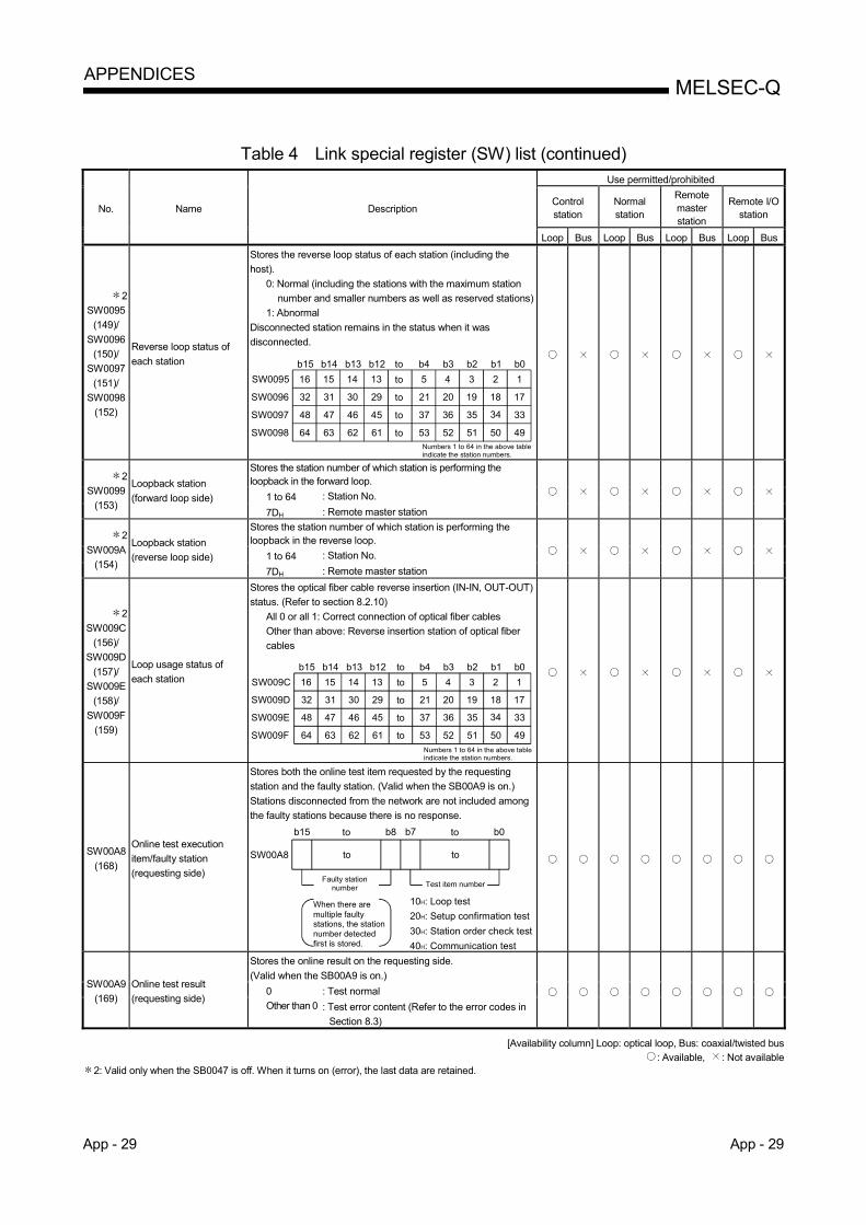
App - 29 App - 29
MELSEC-Q APPENDICES
Table 4 Link special register (SW) list (continued)
No. Name Description
Use permitted/prohibited
Control station
Normal station
Remote master station
Remote I/O station
Loop Bus Loop Bus Loop Bus Loop Bus
2
SW0095
(149)/
SW0096
(150)/
SW0097
(151)/
SW0098
(152)
Reverse loop status of
each station
Stores the reverse loop status of each station (including the
host).
0: Normal (including the stations with the maximum station
number and smaller numbers as well as reserved stations)
1: Abnormal
Disconnected station remains in the status when it was
disconnected.
16
32
48
64
15 14 13 5 4 3 2 1
31 30
47 46
63 62
29
45
61
21 20 19 18 17
37 36 35 34 33
53 52 51 50 49
to
to
to
to
b15 b14 b13 b12 b4 b3 b2 b1 b0
SW0095
SW0096
SW0097
SW0098
to
Numbers 1 to 64 in the above table indicate the station numbers.
2
SW0099
(153)
Loopback station
(forward loop side)
Stores the station number of which station is performing the loopback in the forward loop.
1 to 64 : Station No.
7DH : Remote master station
2
SW009A
(154)
Loopback station
(reverse loop side)
Stores the station number of which station is performing the loopback in the reverse loop.
1 to 64 : Station No.
7DH : Remote master station
2
SW009C
(156)/
SW009D
(157)/
SW009E
(158)/
SW009F
(159)
Loop usage status of
each station
Stores the optical fiber cable reverse insertion (IN-IN, OUT-OUT)
status. (Refer to section 8.2.10)
All 0 or all 1: Correct connection of optical fiber cables
Other than above: Reverse insertion station of optical fiber
cables
16
32
48
64
15 14 13 5 4 3 2 1
31 30
47 46
63 62
29
45
61
21 20 19 18 17
37 36 35 34 33
53 52 51 50 49
to
to
to
to
b15 b14 b13 b12 b4 b3 b2 b1 b0
SW009C
SW009D
SW009E
SW009F
to
Numbers 1 to 64 in the above table indicate the station numbers.
SW00A8
(168)
Online test execution
item/faulty station
(requesting side)
Stores both the online test item requested by the requesting
station and the faulty station. (Valid when the SB00A9 is on.)
Stations disconnected from the network are not included among
the faulty stations because there is no response.
SW00A8
b15 b0
to
to b8 b7
to
to
Test item number
10H: Loop test
20H: Setup confirmation test
30H: Station order check test
40H: Communication test
When there are multiple faulty stations, the station number detected first is stored.
Faulty station number
SW00A9
(169)
Online test result
(requesting side)
Stores the online result on the requesting side.
(Valid when the SB00A9 is on.)
0 : Test normal
Other than 0 : Test error content (Refer to the error codes in
Section 8.3)
[Availability column] Loop: optical loop, Bus: coaxial/twisted bus : Available, : Not available
2: Valid only when the SB0047 is off. When it turns on (error), the last data are retained.

App - 30 App - 30
MELSEC-Q APPENDICES
Table 4 Link special register (SW) list (continued)
No. Name Description
Use permitted/prohibited
Control station
Normal station
Remote master station
Remote I/O station
Loop Bus Loop Bus Loop Bus Loop Bus
SW00AA
(170)
Online test execution item
(responding side)
Stores the online test items on the responding side.
(Valid when the SB00AB is on.)
Stations disconnected from the network are not included among
the faulty stations because there is no response.
SW00AA
b15 b0
to
to b8 b7
to
to
Item number
10H: Loop test
20H: Setup confirmation test
30H: Station order check test
40H: Communication test
0 0
SW00AB
(171)
Online test result
(responding side)
Stores the online test result of the responding side.
(Valid when the SB00AB is on.)
0 : Test normal
Other than 0 : Test error content (Refer to the error codes in
Section 8.3)
SW00AC
(172)
Offline test execution
item/faulty station
(requesting side)
Stores the offline test items and faulty station on the requesting
side. (Valid when the SB00AD is on.) Stations disconnected from
the network are not included among the faulty stations because
there is no response.
Any given station number (0 to 64, 7DH) is saved in the
maximum faulty station number (b8 to b15) for the loop test.
SW00AC
b15 b0
to
to b8 b7
to
to
Maximum faulty station number Item number
3: Loop test (forward loop)
4: Loop test (reverse loop)
5: Station-to-station test (master station)
6: Station-to-station test (slave station)
7: Self-loopback test
8: Internal self-loopback test
SW00AD
(173)
Offline test result
(requesting side)
Stores the offline result of the requesting side.
(Valid when the SB00AD is on.)
0 : Test normal
Other than 0 : Test error content (Refer to the error codes in
Section 8.3)
SW00AE
(174)
Offline test execution item
(responding side)
Stores the request-side offline test items and error stations. (Enabled when SB00AF is on.) When station breaks from network, it is not included with error stations because there is no response.
SW00AA
b15 b0
to
to b8 b7
to
to
Item number
3: Loop test (forward loop)
4: Loop test (reverse loop)
0 0
SW00AF
(175)
Offline test result
(responding side)
Stores results of request-side offline test.
(Enabled when SB00AF is on.)
0 : Test normal
Other than 0 : Test error content (Refer to the error codes in
Section 8.3)
[Availability column] Loop: optical loop, Bus: coaxial/twisted bus
: Available, : Not available

App - 31 App - 31
MELSEC-Q APPENDICES
Table 4 Link special register (SW) list (continued)
No. Name Description
Use permitted/prohibited
Control station
Normal station
Remote master station
Remote I/O station
Loop Bus Loop Bus Loop Bus Loop Bus
2
SW00B0
(176)/
SW00B1
(177)/
SW00B2
(178)/
SW00B3
(179)
Multiplex transmission
status (1)
Stores each station's forward loop usage status during multiplex transmission.
0: Uses other than the forward loop 1: Uses the forward loop
16
32
48
64
15 14 13 5 4 3 2 1
31 30
47 46
63 62
29
45
61
21 20 19 18 17
37 36 35 34 33
53 52 51 50 49
to
to
to
to
b15 b14 b13 b12 b4 b3 b2 b1 b0
SW00B0
SW00B1
SW00B2
SW00B3
to
Numbers 1 to 64 in the above table indicate the station numbers.
2
SW00B4
(180)/
SW00B5
(181)/
SW00B6
(182)/
SW00B7
(183)
Multiplex transmission
status (2)
Stores each station's reverse loop usage status during multiplex transmission.
0: Uses other than the reverse loop 1: Uses the reverse loop
16
32
48
64
15 14 13 5 4 3 2 1
31 30
47 46
63 62
29
45
61
21 20 19 18 17
37 36 35 34 33
53 52 51 50 49
to
to
to
to
b15 b14 b13 b12 b4 b3 b2 b1 b0
SW00B4
SW00B5
SW00B6
SW00B7
to
Numbers 1 to 64 in the above table indicate the station numbers.
3
SW00B8
(184)
UNDER on the forward
loop side
Optical loop: Stores the number of "UNDER" errors on the
forward loop side.
Coaxial/twisted bus: Stores the number of "UNDER" errors.
Other than 0: Number of errors
Turning ON Clear communication error count (SB0006) clears
the stored value.
3
SW00B9
(185)
CRC on the forward loop
side
Optical loop: Stores the number of "CRC" errors on the forward
loop side.
Coaxial/twisted bus: Stores the number of "CRC" errors.
Other than 0: Number of errors
Turning ON Clear communication error count (SB0006) clears
the stored value.
3
SW00BA
(186)
OVER on the forward
loop side
Optical loop: Stores the number of "OVER" errors on the forward
loop side.
Coaxial/twisted bus: Stores the number of "OVER" errors.
Other than 0: Number of errors
Turning ON Clear communication error count (SB0006) clears
the stored value.
3
SW00BB
(187)
Short frame on the
forward loop side
Optical loop: Stores the number of "short frame" errors on the
forward loop side.
Coaxial/twisted bus: Stores the number of "short frame" errors.
Other than 0: Number of errors
Turning ON Clear communication error count (SB0006) clears
the stored value.
3
SW00BC
(188)
Abort on the forward loop
side (AB, IF)
Optical loop: Stores the number of "AB.IF" errors on the forward
loop side.
Coaxial/twisted bus: Stores the number of "AB.IF" errors.
Other than 0: Number of errors
Turning ON Clear communication error count (SB0006) clears
the stored value.
[Availability column] Loop: optical loop, Bus: coaxial/twisted bus
: Available, : Not available 2: Valid only when the SB0047 is off. When it turns on (error), the last data are retained. 3: To reset the SW00B8 to SW00C7, turn on the SB0006.
The number of times information stored in the SW00B8 to SW00C7 will not cause any problems if they are counted up gradually over a long period of time. If they are counted up rapidly in a short period of time (while monitoring with GX Developer, etc.), the cable may be faulty.

App - 32 App - 32
MELSEC-Q APPENDICES
Table 4 Link special register (SW) list (continued)
No. Name Description
Use permitted/prohibited
Control station
Normal station
Remote master station
Remote I/O station
Loop Bus Loop Bus Loop Bus Loop Bus
3
SW00BD
(189)
Timeout on the forward
loop side (TIME)
Optical loop: Stores the number of "TIME" errors on the forward
loop side.
Coaxial/twisted bus: Stores the number of "TIME" errors.
Other than 0: Number of errors
Turning ON Clear communication error count (SB0006) clears
the stored value.
3
SW00BE
(190)
Receiving 2k bytes or
more on forward loop side
(DATA)
Optical loop: Stores the number of "DATA" errors on the forward
loop side.
Coaxial/twisted bus: Stores the number of "DATA" errors.
Other than 0: Number of errors
Turning ON Clear communication error count (SB0006) clears
the stored value.
3
SW00BF
(191)
DPLL error on the forward
loop side
Optical loop: Stores the number of "DPLL" errors on the forward
loop side.
Coaxial/twisted bus: Stores the number of "DPLL" errors.
Other than 0: Number of errors
Turning ON Clear communication error count (SB0006) clears
the stored value.
3
SW00C0
(192)
UNDER on the reverse
loop side
Accumulates and stores the number of "UNDER" errors on the
reverse loop side.
Other than 0: Number of errors
Turning ON Clear communication error count (SB0006) clears
the stored value.
3
SW00C1
(193)
CRC on the reverse loop
side
Accumulates and stores the number of "CRC" errors on the
reverse loop side.
Other than 0: Number of errors
Turning ON Clear communication error count (SB0006) clears
the stored value.
3
SW00C2
(194)
OVER on the reverse
loop side
Accumulates and stores the number of "OVER" errors on the
reverse loop side.
Other than 0: Number of errors
Turning ON Clear communication error count (SB0006) clears
the stored value.
3
SW00C3
(195)
Short frame on the
reverse loop side
Accumulates and stores the number of "Short frame" errors on
the reverse loop side.
Other than 0: Number of errors
Turning ON Clear communication error count (SB0006) clears
the stored value.
3
SW00C4
(196)
Abort on the reverse loop
side (AB, IF)
Accumulates and stores the number of "AB.IF" errors on the
reverse loop side.
Other than 0: Number of errors
Turning ON Clear communication error count (SB0006) clears
the stored value.
3
SW00C5
(197)
Timeout on the reverse
loop side (TIME)
Accumulates and stores the number of "TIME" errors on the
reverse loop side.
Other than 0: Number of errors
Turning ON Clear communication error count (SB0006) clears
the stored value.
3
SW00C6
(198)
Receiving 2k bytes or
more on reverse loop side
(DATA)
Accumulates and stores the number of "DATA" errors on the
reverse loop side.
Other than 0: Number of errors
Turning ON Clear communication error count (SB0006) clears
the stored value.
[Availability column] Loop: optical loop, Bus: coaxial/twisted bus
: Available, : Not available
3: To reset from the SW00B8 to C7, turn on the SB0006.
The numbers of times stored in the SW00B8 to SW00C7 will not cause any problems if they are counting up gradually over a long period of time. If they are
counted up rapidly in a short period of time (while monitoring with GX Developer, etc.), the cable may be faulty.

App - 33 App - 33
MELSEC-Q APPENDICES
Table 4 Link special register (SW) list (continued)
No. Name Description
Use permitted/prohibited
Control station
Normal station
Remote master station
Remote I/O station
Loop Bus Loop Bus Loop Bus Loop Bus
3
SW00C7
(199)
DPLL error on reverse
loop side
Accumulates and stores the number of "DPLL" errors on the
reverse loop side.
Other than 0: Number of errors
Turning ON Clear communication error count (SB0006) clears
the stored value.
4
SW00C8
(200)
Number of retries on the
forward loop side
Optical loop: Stores the number of retries on the forward loop
side.
Coaxial/twisted bus: Stores the number of retries.
Other than 0: Number of errors
Turning ON Clear retry count (SB0005) clears the stored value.
4
SW00C9
(201)
Number of retries on the
reverse loop side
Accumulates and stores the number of retries on the reverse
loop side.
Other than 0: Number of errors
Turning ON Clear retry count (SB0005) clears the stored value.
5
SW00CC
(204)
Line error on the forward
loop side
Accumulates and stores the number of detected line errors on
the forward loop side.
Other than 0: Number of detected line errors
Turning ON Clear forward loop transmission errors (SB0007)
clears the stored value.
6
SW00CD
(205)
Line error on the reverse
loop side
Accumulates and stores the number of detected line errors on
the reverse loop side.
Other than 0: Number of detected line errors
Turning ON Clear reverse loop transmission errors (SB0008)
clears the stored value.
7
SW00CE
(206)
Number of loop switches
Accumulates and stores the number of loop checks conducted.
Other than 0: Number of loop switches
Turning ON Clear loop switch count (SB0009) clears the stored
value.
7
SW00CF
(207)
Loop switch data pointer
Stores the pointer that indicates the next loop switch data.
0 to 15: Loop switch data (SW00D0 to SW00DF)
Turning ON Clear loop switch count (SB0009) clears the stored
value.
[Availability column] Loop: optical loop, Bus: coaxial/twisted bus
: Available, : Not available
3: To reset from the SW00B8 to C7, turn on the SB0006.
The numbers of times stored in the SW00B8 to SW00C7 will not cause any problems if they are counting up gradually over a long period of time. If they are
counted up rapidly in a short period of time (while monitoring with GX Developer, etc.), the cable may be faulty.
4: This may be counted up at power on/reset, but it is not an error.
Clear with the SB0005 when the number of retries is not required before starting data linking.
5: To reset the SW00CC, turn on the SB0007. 6: To reset the SW00CD, turn on the SB0008. 7: To reset the SW00CE to SW00E7, turn on the SB0009.

App - 34 App - 34
MELSEC-Q APPENDICES
Table 4 Link special register (SW) list (continued)
No. Name Description
Use permitted/prohibited
Control station
Normal station
Remote master station
Remote I/O station
Loop Bus Loop Bus Loop Bus Loop Bus
7 SW00D0
(208) to
SW00DF (223)
Loop switch data
Stores the cause and status of the loop switch. Whether the data are overwritten or retained is set in the common parameters.
to
Cause
b15 to b8 b7 b6 b5 b4 b3 b2 b1 b0
Status after switching
SW00D0
SW00DFto
<Cause> The bit corresponding to each error is set to 1.
All 0: Return direction b0: Forward loop H/W error b1: Reverse loop H/W error b2: Forward loop forced error b3: Reverse loop forced error b4: Forward loop continuous
communication error b5: Reverse loop continuous
communication error b6: Forward loop continuous line
error b7: Reverse loop continuous line
error
< Status after the switching> 0: Multiplex transmission
(Forward loop/reverse loop normal)
1: Data link by forward loop
2: Data linking by reverse loop
3: Data linking by loopback
Turning ON Clear loop switch count (SB0009) clears the stored value.
7 8
SW00E0
(224)
to
SW00E7
(231)
Switch request station
Stores the number of the stations that requested the loop switch. b15 b0to b8 b7 to
Odd numbered switch station
Even numbered switch station
SW00E0
SW00E7to
Turning ON Clear loop switch count (SB0009) clears the stored value.
2
SW00E8
(232)
to
SW00EB
(235)
Module type of each
station
Stores each station's module type.
0: MELSECNET/10 module
1: MELSECNET/H module
16
32
48
64
15 14 13 5 4 3 2 1
31 30
47 46
63 62
29
45
61
21 20 19 18 17
37 36 35 34 33
53 52 51 50 49
to
to
to
to
b15 b14 b13 b12 b4 b3 b2 b1 b0
SW00E8
SW00E9
SW00EA
SW00EB
to
Numbers 1 to 64 in the above table indicate the station numbers.
2
SW00EC
(236)
Low-speed cyclic
transmission start
execution results
Stores execution results for low-speed cyclic transmission start
execution results.
0 : Test normal
Other than 0 : Test error content (Refer to the error codes in
Section 8.3)
[Availability column] Loop: optical loop, Bus: coaxial/twisted bus : Available, : Not available
2: Valid only when the SB0047 is off. When it turns on (error), the last data are retained. 7: To reset the SW00CE to SW00E7, turn on the SB0009. 8: For the loop switch request station, stations other than the ones at both ends of the loop may be stored because the loop switch request is issued by the
station that first detected the loop error.
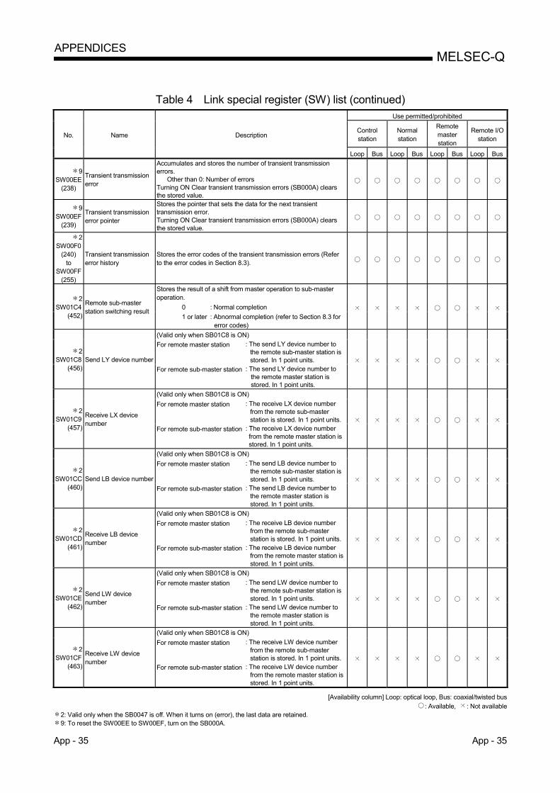
App - 35 App - 35
MELSEC-Q APPENDICES
Table 4 Link special register (SW) list (continued)
No. Name Description
Use permitted/prohibited
Control station
Normal station
Remote master station
Remote I/O station
Loop Bus Loop Bus Loop Bus Loop Bus
9 SW00EE
(238)
Transient transmission error
Accumulates and stores the number of transient transmission errors.
Other than 0: Number of errors Turning ON Clear transient transmission errors (SB000A) clears the stored value.
9 SW00EF
(239)
Transient transmission error pointer
Stores the pointer that sets the data for the next transient transmission error. Turning ON Clear transient transmission errors (SB000A) clears the stored value.
2 SW00F0
(240) to
SW00FF (255)
Transient transmission error history
Stores the error codes of the transient transmission errors (Refer to the error codes in Section 8.3).
2 SW01C4
(452)
Remote sub-master station switching result
Stores the result of a shift from master operation to sub-master operation.
0 : Normal completion
1 or later : Abnormal completion (refer to Section 8.3 for error codes)
2 SW01C8
(456) Send LY device number
(Valid only when SB01C8 is ON)
For remote master station : The send LY device number to the remote sub-master station is stored. In 1 point units.
For remote sub-master station : The send LY device number to the remote master station is stored. In 1 point units.
2 SW01C9
(457)
Receive LX device number
(Valid only when SB01C8 is ON)
For remote master station : The receive LX device number from the remote sub-master station is stored. In 1 point units.
For remote sub-master station : The receive LX device number from the remote master station is stored. In 1 point units.
2 SW01CC
(460) Send LB device number
(Valid only when SB01C8 is ON)
For remote master station : The send LB device number to the remote sub-master station is stored. In 1 point units.
For remote sub-master station : The send LB device number to the remote master station is stored. In 1 point units.
2 SW01CD
(461)
Receive LB device number
(Valid only when SB01C8 is ON)
For remote master station : The receive LB device number from the remote sub-master station is stored. In 1 point units.
For remote sub-master station : The receive LB device number from the remote master station is stored. In 1 point units.
2 SW01CE
(462)
Send LW device number
(Valid only when SB01C8 is ON)
For remote master station : The send LW device number to the remote sub-master station is stored. In 1 point units.
For remote sub-master station : The send LW device number to the remote master station is stored. In 1 point units.
2 SW01CF
(463)
Receive LW device number
(Valid only when SB01C8 is ON)
For remote master station : The receive LW device number from the remote sub-master station is stored. In 1 point units.
For remote sub-master station : The receive LW device number from the remote master station is stored. In 1 point units.
[Availability column] Loop: optical loop, Bus: coaxial/twisted bus
: Available, : Not available 2: Valid only when the SB0047 is off. When it turns on (error), the last data are retained. 9: To reset the SW00EE to SW00EF, turn on the SB000A.

App - 36 App - 36
MELSEC-Q APPENDICES
Table 4 Link special register (SW) list (continued)
No. Name Description
Use permitted/prohibited
Control station
Normal station
Remote master station
Remote I/O station
Loop Bus Loop Bus Loop Bus Loop Bus
2
SW01E0
(480)/
SW01E1
(481)/
SW01E2
(482)/
SW01E3
(483)
Network type
consistency check
Indicates whether there is a mismatch between the network types of the control station and normal stations on the network. • When the control station is in the MELSECNET/H Extended
mode 0: Set to the MELSECNET/H Extended mode. (Including
stations of station Nos. greater than the maximum, reserved stations and communication error stations)
1: Set to the MELSECNET/H mode or MELSECNET/10 mode. • When the control station is in the MELSECNET/H mode or
MELSECNET/10 mode 0: Set to the MELSECNET/H mode or MELSECNET/10 mode.
(Including stations of station Nos. greater than the maximum, reserved stations and communication error stations)
1: Set to the MELSECNET/H Extended mode.
16
32
48
64
15 14 13 5 4 3 2 1
31 30
47 46
63 62
29
45
61
21 20 19 18 17
37 36 35 34 33
53 52 51 50 49
to
to
to
to
b15 b14 b13 b12 b4 b3 b2 b1 b0
SW01E0
SW01E1
SW01E2
SW01E3
1 to 64 in the table indicate the station Nos.
to
2
SW01F4
(500)/
SW01F5
(501)/
SW01F6
(502)/
SW01F7
(503)
Redundant system
status (1)
Indicates the operation mode of each station's CPU. 0: Backup mode (including the single CPU system) (including
stations exceeding the maximum station number and reserved stations)
1: Separate mode
16
32
48
64
15 14 13 5 4 3 2 1
31 30
47 46
63 62
29
45
61
21 20 19 18 17
37 36 35 34 33
53 52 51 50 49
b15 b14 b13 b12 b4 b3 b2 b1 b0
SW01F4
SW01F5
SW01F6
SW01F7
to
to
to
to
to
Numbers 1 to 64 in the above table indicate the station numbers.
2
SW01F8
(504)/
SW01F9
(505)/
SW01FA
(506)/
SW01FB
(507)
Redundant system
status (2)
Indicates the pairing setting status of each station. In the case of a redundant system, the bit of the station with the larger number is turned on (1).
0: No pairing designation (including the single CPU system) (including stations exceeding the maximum station number)
1: Station with pairing designation
16
32
48
64
15 14 13 5 4 3 2 1
31 30
47 46
63 62
29
45
61
21 20 19 18 17
37 36 35 34 33
53 52 51 50 49
b15 b14 b13 b12 b4 b3 b2 b1 b0
SW01F8
SW01F9
SW01FA
SW01FB
Numbers 1 to 64 in the above table indicate the station numbers.
to
to
to
to
to
2
SW01FC
(508)/
SW01FD
(509)/
SW01FE
(510)/
SW01FF
(511)
Redundant system
status (3)
Indicates the operation status of each station's CPU (control system/standby system).
0: The host station CPU is on the control system (including the single CPU system) (including stations exceeding the maximum station number and reserved stations).
1: The host system CPU is on the standby system.
16
32
48
64
15 14 13 5 4 3 2 1
31 30
47 46
63 62
29
45
61
21 20 19 18 17
37 36 35 34 33
53 52 51 50 49
b15 b14 b13 b12 b4 b3 b2 b1 b0
SW01FC
SW01FD
SW01FE
SW01FF
Numbers 1 to 64 in the above table indicate the station numbers.
to
to
to
to
to
[Availability column] Loop: optical loop, Bus: coaxial/twisted bus
: Available, : Not available 2: Valid only when the SB0047 is off. When it turns on (error), the last data are retained.

App - 37 App - 37
MELSEC-Q APPENDICES
Appendix 5 Screwdriver
The following is a screwdriver used for connecting and removing cables to and from a
spring clamp terminal block of the QJ71NT11B.
Model Manufacturer
SZS 0,6×3,5 Phoenix Contact
REMARKS
For inquiries and orders, please contact your local Phoenix Contact.
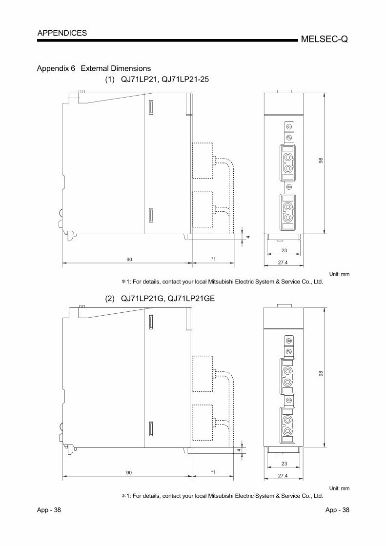
App - 38 App - 38
MELSEC-Q APPENDICES
Appendix 6 External Dimensions
(1) QJ71LP21, QJ71LP21-25
90 *1
98
234
27.4 Unit: mm
1: For details, contact your local Mitsubishi Electric System & Service Co., Ltd.
(2) QJ71LP21G, QJ71LP21GE
90 *1
98
23
4
27.4 Unit: mm
1: For details, contact your local Mitsubishi Electric System & Service Co., Ltd.
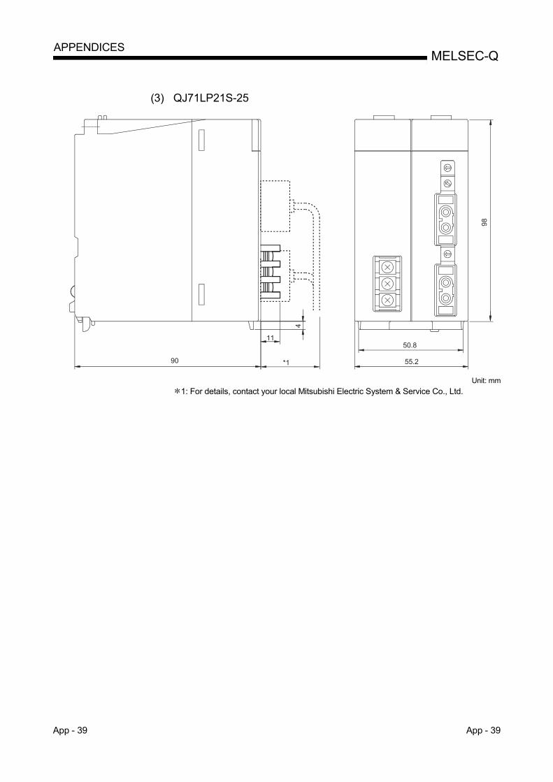
App - 39 App - 39
MELSEC-Q APPENDICES
(3) QJ71LP21S-25
11
55.290
4
50.8
98
*1
Unit: mm
1: For details, contact your local Mitsubishi Electric System & Service Co., Ltd.

App - 40 App - 40
MELSEC-Q APPENDICES
(4) QJ71BR11
55
98
27.490
23
4
Unit: mm
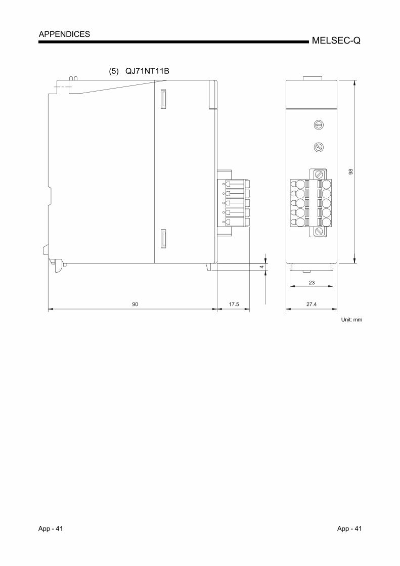
App - 41 App - 41
MELSEC-Q APPENDICES
(5) QJ71NT11B
27.490
98
17.5
23
4
Unit: mm

App - 42 App - 42
MELSEC-Q APPENDICES
MEMO

Index - 1 Index - 1
INDEX
[A] Applicable Systems ......................................... 2-7
[C]
Coaxial cable ................................................... 3-6
Common parameter
Send range for each station
(LB/LW settings) ........................................ 5-14
Send range for each station
(LX/LY settings) ......................................... 5-15
Specification of the I/O master station ...... 5-16
Specification of the reserved station ......... 5-16
Control Station Shift Time ................... A-17, 3-51
Cyclic transmission........................................ 3-15
Communication speed setting ...................... 5-12
CC-Link Ver. 1.10-compatible cable ............. 3-13
[D]
Dedicated instruction error code storage
location .......................................................... 8-36
[E]
Error code
Checking for dedicated instruction error ... 8-36
Error code list ............................................. 8-37
How to check error codes ......................... 8-32
External power supply ................................... 6-31
[F] Function ................................................ 2-20, 3-14
[G]
Group function ............................................... 7-27
Group No. ............................................ A-17, 5-10
[H]
H/W information ............................................. 8-47
[ I ]
Inter-link data transfer
Inter-link data transfer function.................... 7-6
Interlink transmission parameters ............... 7-7
Inter-link data transfer stations .................... 7-8
[L]
Link dedicated instruction ............... 6-9,6-30,8-36
Link device
Direct device (Link direct device) .................7-2
Address specification range .........................7-4
Link refresh .................................................... 3-30
Link refresh assignment image ..................... 5-26
Link scan ....................................................... 3-30
Link special relay (SB) .......................6-13, App-6
Link special register (SW) ............... 6-13, App-18
Low-speed cyclic transmission ........................7-9
[M]
MELSECNET/H Extended Mode ..... 3-1, 3-3, 5-7
MELSECNET/H Mode ...................... 3-1, 3-3, 5-7
MELSECNET/10 Mode ..................... 3-1, 3-3, 5-7
Message sending .......................................... 7-28
Module error history ...................................... 8-34
Multiple CPU system ........................................2-8
Multiplex transmission ................................. 7-123
[N]
Network diagnostics
Error history monitor .................................. 8-15
Error history detail monitoring ................... 8-17
Network monitor details ............................. 8-11
Station order check test ............................ 4-44
Communication test................................... 4-45
Host information ...........................................8-5
Setup confirmation test ............................. 4-43
Other station information ..............................8-7
Loop test .................................................... 4-42
Network setting
Starting I/O No. .............................................5-9
Network No. ..................................................5-9
Total stations ............................................. 5-10
Group No. .................................................. 5-10
Network test
Stopping/restarting the cyclic
transmission ............................................ 7-129
Stopping link refreshing ........................... 7-129
Network type
MELSECNET/H Extended Mode
............................................... 3-1, 3-3, 3-4, 5-7
MELSECNET/H Mode .......... 3-1, 3-3, 3-4, 5-7
MELSECNET/10 Mode ................. 3-1, 3-3, 5-7
I

Index - 2 Index - 2
[O] Operation mode
Online ......................................................... 5-11
Online debug mode ................................... 5-11
Offline ......................................................... 5-11
Forward loop test ....................................... 5-11
Reverse loop test ....................................... 5-11
Station-to-station test
(station to execute test) ............................. 5-11
Station-to-station test
(station to be tested) .................................. 5-11
Optical fiber cable ............................................ 3-5
[P] Performance Specifications ............................ 3-1
Coaxial bus system ............................ 2-1, 4-22
Optical loop system ............................ 2-1, 4-19
Twisted bus system ............................ 2-2, 4-27
[R]
RAS function
Control station switch function .................. 3-19
Control station return control function ....... 3-20
Station detach function .............................. 3-25
Automatic return function .......................... 3-18
Diagnostic function .................................... 3-28
Loopback function ..................................... 3-21
READ instruction ........................................... 7-53
RECV instruction ........................................... 7-41
RECVS instruction ...................................... 7-117
Redundant system
System switching request ....................... 7-150
Outline of the redundant system operation
................................................................. 7-134
Redundant settings ................................. 7-149
Network configuration .............................. 7-137
Pairing setting .......................................... 7-145
Refresh parameter ........................................ 5-25
REQ instruction ............................................. 7-71
Routing function
Routing parameter ..................................... 7-21
Transmission delay time ........................... 7-24
RRUN instruction ........................................... 7-91
RSTOP instruction ........................................ 7-94
RTMRD instruction ...................................... 7-100
RTMWR instruction ..................................... 7-102
RTWRITE instruction .................................. 7-160
[S] SEND instruction ........................................... 7-36
Shielded twisted pair cable ..............................3-9
Simple dual-structured network
Regular network ...................................... 7-124
Standby network ...................................... 7-124
Simple dual-structured
Control special relay ................................ 7-125
Program ................................................... 7-127
SREAD instruction ........................................ 7-53
Supplementary setting
Monitoring time .......................................... 5-17
Parameter name ........................................ 5-17
Constant scan ............................................ 5-18
Maximum No. of return to system
stations in 1 scan ....................................... 5-18
With multiplex transmission ...................... 5-18
There is a data link through the sub-
controlling station when the controlling
station is down ........................................... 5-18
Block send data assurance per station/Block
receive data assurance per station ........... 5-18
Transient setting ........................................ 5-19
Specification of low-speed cyclic
transmission .............................................. 5-19
Switch settings
Station number setting switch .............. 4-3, 4-6
Mode setting switch .............................. 4-4, 4-7
Station number/mode setting switch ............4-6
SWRITE instruction ....................................... 7-58
System error history ...................................... 8-34
[T]
Test
Station-to-station test ................................ 4-28
Self-loopback test ...................................... 4-13
Forward loop/reverse loop test ................. 4-36
Internal self-loopback test ......................... 4-15
Hardware test ............................................ 4-17
Transient transmission
Parameter setting ...................................... 7-17
Range ........................................................ 7-18
[W]
WRITE instruction ......................................... 7-59
I

Index - 3 Index - 3
[Z] ZNRD instruction ........................................... 7-82
ZNWR instruction .......................................... 7-84
[0 to 9]
32-bit data assurance ...................................... 6-5

WARRANTY
Please confirm the following product warranty details before using this product.
1. Gratis Warranty Term and Gratis Warranty RangeIf any faults or defects (hereinafter "Failure") found to be the responsibility of Mitsubishi occurs during use of the product within the gratis warranty term, the product shall be repaired at no cost via the sales representative or Mitsubishi Service Company.However, if repairs are required onsite at domestic or overseas location, expenses to send an engineer will be solely at the customer's discretion. Mitsubishi shall not be held responsible for any re-commissioning, maintenance, or testing on-site that involves replacement of the failed module.[Gratis Warranty Term]The gratis warranty term of the product shall be for one year after the date of purchase or delivery to a designated place.Note that after manufacture and shipment from Mitsubishi, the maximum distribution period shall be six (6) months, and the longest gratis warranty term after manufacturing shall be eighteen (18) months. The gratis warranty term of repair parts shall not exceed the gratis warranty term before repairs.[Gratis Warranty Range](1) The range shall be limited to normal use within the usage state, usage methods and usage environment, etc., which
follow the conditions and precautions, etc., given in the instruction manual, user's manual and caution labels on the product.
(2) Even within the gratis warranty term, repairs shall be charged for in the following cases.1. Failure occurring from inappropriate storage or handling, carelessness or negligence by the user. Failure caused
by the user's hardware or software design.2. Failure caused by unapproved modifications, etc., to the product by the user.3. When the Mitsubishi product is assembled into a user's device, Failure that could have been avoided if functions
or structures, judged as necessary in the legal safety measures the user's device is subject to or as necessary by industry standards, had been provided.
4. Failure that could have been avoided if consumable parts (battery, backlight, fuse, etc.) designated in the instruction manual had been correctly serviced or replaced.
5. Failure caused by external irresistible forces such as fires or abnormal voltages, and Failure caused by force majeure such as earthquakes, lightning, wind and water damage.
6. Failure caused by reasons unpredictable by scientific technology standards at time of shipment from Mitsubishi.7. Any other failure found not to be the responsibility of Mitsubishi or that admitted not to be so by the user.
2. Onerous repair term after discontinuation of production(1) Mitsubishi shall accept onerous product repairs for seven (7) years after production of the product is discontinued.
Discontinuation of production shall be notified with Mitsubishi Technical Bulletins, etc.(2) Product supply (including repair parts) is not available after production is discontinued.
3. Overseas serviceOverseas, repairs shall be accepted by Mitsubishi's local overseas FA Center. Note that the repair conditions at each FA Center may differ.
4. Exclusion of loss in opportunity and secondary loss from warranty liabilityRegardless of the gratis warranty term, Mitsubishi shall not be liable for compensation to:(1) Damages caused by any cause found not to be the responsibility of Mitsubishi.(2) Loss in opportunity, lost profits incurred to the user by Failures of Mitsubishi products.(3) Special damages and secondary damages whether foreseeable or not, compensation for accidents, and
compensation for damages to products other than Mitsubishi products.(4) Replacement by the user, maintenance of on-site equipment, start-up test run and other tasks.
5. Changes in product specificationsThe specifications given in the catalogs, manuals or technical documents are subject to change without prior notice.

Ethernet is a registered trademark of Fuji Xerox Co., Ltd. in Japan.
The company names, system names and product names mentioned in this manual are either registered
trademarks or trademarks of their respective companies.
In some cases, trademark symbols such as 'TM' or '®' are not specified in this manual.
SH(NA)-080049-Q


SH(NA)-080049-Q(1711)MEE
MODEL: Q-NET/10H-R-E
MODEL CODE: 13JF92
Specifications subject to change without notice.
When exported from Japan, this manual does not require application to theMinistry of Economy, Trade and Industry for service transaction permission.
HEAD OFFICE : TOKYO BUILDING, 2-7-3 MARUNOUCHI, CHIYODA-KU, TOKYO 100-8310, JAPANNAGOYA WORKS : 1-14 , YADA-MINAMI 5-CHOME , HIGASHI-KU, NAGOYA , JAPAN