q46-83 kmno4 auto-chem-bati q46/83 auto-chem permanganate monitor part 1 – introduction 6 o&m...
TRANSCRIPT

Model Q46/83 Auto-Chem Permanganate
Monitor
Home Office European Office Analytical Technology, Inc. ATI (UK) Limited 6 Iron Bridge Drive Unit 1 & 2 Gatehead Business Park Collegeville, PA 19426 Delph New Road, Delph Saddleworth OL3 5DE Ph:(800) 959-0299 Ph: 0800-018-4020 (610) 917-0991 + 44 (0) 1457-873-318 Fax: (610) 917-0992 Fax: + 44 (0) 1457-874-468 Email: [email protected] Email:[email protected]

PRODUCT WARRANTY Analytical Technology, Inc. (Manufacturer) warrants to the Customer that if any part(s) of the Manufacturer's products proves to be defective in materials or workmanship within the earlier of 18 months of the date of shipment or 12 months of the date of start-up, such defective parts will be repaired or replaced free of charge. Inspection and repairs to products thought to be defective within the warranty period will be completed at the Manufacturer's facilities in Collegeville, PA. Products on which warranty repairs are required shall be shipped freight prepaid to the Manufacturer. The product(s) will be returned freight prepaid and allowed if it is determined by the manufacturer that the part(s) failed due to defective materials or workmanship. This warranty does not cover consumable items, batteries, or wear items subject to periodic replacement including lamps and fuses. Gas sensors, except oxygen sensors, are covered by this warranty, but are subject to inspection for evidence of extended exposure to excessive gas concentrations. Should inspection indicate that sensors have been expended rather than failed prematurely, the warranty shall not apply. The Manufacturer assumes no liability for consequential damages of any kind, and the buyer by acceptance of this equipment will assume all liability for the consequences of its use or misuse by the Customer, his employees, or others. A defect within the meaning of this warranty is any part of any piece of a Manufacturer's product which shall, when such part is capable of being renewed, repaired, or replaced, operate to condemn such piece of equipment. This warranty is in lieu of all other warranties (including without limiting the generality of the foregoing warranties of merchantability and fitness for a particular purpose), guarantees, obligations or liabilities expressed or implied by the Manufacturer or its representatives and by statute or rule of law. This warranty is void if the Manufacturer's product(s) has been subject to misuse or abuse, or has not been operated or stored in accordance with instructions, or if the serial number has been removed. Analytical Technology, Inc. makes no other warranty expressed or implied except as stated above.

2
O&M Manual Rev-B (11/13)
Table of Contents
PART 1 - INTRODUCTION ................................. 4 1.1 General ...................................................... 4 1.2 Q46/83 System Specifications .................. 6 1.3 Q46/83 Performance Specifications .......... 7
PART 2 – MECHANICAL INSTALLATION ..... 8 2.1 General ...................................................... 8 2.2 Wall Mount Bracket .................................. 9 2.3 Panel Mount, AC Powered Monitor ........12 2.4 Auto-Chem Mounting ..............................13 2.5 Reagent Bottle Bracket and Pickup Assembly .............................................................15 2.6 Inlet and Drain Connections ....................16
PART 3 – ELECTRICAL INSTALLATION ......17 3.1 General .....................................................17 3.3 Q46/83 Sensor Wiring .............................19 3.4 Relay Wiring ............................................20 3.2 Auto-Chem Power Panel ..........................21 3.2 Auto-Chem Power Panel Wiring .............22
PART 4 – AUTO-CHEM STARTUP ...................23 4.1 General .....................................................23 4.2 Reagent ....................................................23 4.3 Reagent Pump Priming ............................23 4.4 Sensor Preparation ...................................25 4.5 Operation . Error! Bookmark not defined.
PART 5 – CONFIGURATION .............................28 5.1 User Interface ...........................................28
5.11 Keys .....................................................29 5.12 Display .................................................29
5.2 Software ...................................................31 5.21 Software Navigation ...........................31 5.22 Measure Menu [MEASURE] ...............34 5.23 Calibration Menu [CAL].........................35 5.24 Configuration Menu [CONFIG] .........35 5.25 Control Menu [CONTROL] ...............38 5.26 Diagnostics Menu [DIAG] .....................43
PART 6 – CALIBRATION ...................................47 6.1 Calibration ...............................................47
6.11 Zero Cal ...............................................47 6.12 Span Cal ...............................................48 6.13 Mixing a Permanganate Standard ........49
6.2 Temperature Calibration ..........................50
PART 7 – PID CONTROLLER DETAILS .........51 7.1 PID Description .......................................51 7.2 PID Algorithm .........................................51 7.3 Classical PID Tuning ...............................54 7.4 Manual PID Override Control..................54 7.5 Common PID Pitfalls ...............................55
PART 8 – SYSTEM MAINTENANCE ................56 8.1 General .....................................................56 8.2 Analyzer Maintenance .............................56 8.3 Sensor Maintenance .................................56 8.4 Sample Pump Tube Replacement ............56 8.5 Reagent Pump Tube Replacement ...........58 8.6 Air Pump Filter Replacement ..................58
PART 9 – TROUBLESHOOTING ......................59 9.1 General .....................................................59 9.2 External Sources of Problems ..................59 9.3 Analyzer Tests .........................................60 9.4 Display Messages ....................................61
SPARE PARTS ......................................................62

3
O&M Manual Rev-B (11/13)
Table of Figures
FIGURE 1 – DISSOLVED SULFIDE TYPICAL SYSTEM ......................................................................... 5 FIGURE 2 - Q46 ENCLOSURE DIMENSIONS ..................................................................................... 9 FIGURE 3 - WALL OR PIPE MOUNT BRACKET ................................................................................. 10 FIGURE 4 - WALL MOUNTING DIAGRAM ........................................................................................ 11 FIGURE 5 - PIPE MOUNTING DIAGRAM .......................................................................................... 11 FIGURE 6 - PANEL MOUNT CUT-OUT ............................................................................................ 12 FIGURE 7 – AUTO-CHEM ENCLOSURE MOUNTING FEET ................................................................ 13 FIGURE 8 – AUTO-CHEM DIMENSIONAL DRAWING ......................................................................... 14 FIGURE 9 - BOTTLE BRACKET & REAGENT FEED ASSEMBLY ......................................................... 15 FIGURE 10 - LINE POWER CONNECTION ....................................................................................... 18 FIGURE 11 - SENSOR CONNECTION ............................................................................................. 19 FIGURE 12 - RELAY CONTACTS ................................................................................................... 20 FIGURE 13 – AUTO-CHEM CONNECTION PANEL ............................................................................ 21 FIGURE 14 - AUTO-CHEM CUSTOMER WIRING .............................................................................. 22 FIGURE 15 – AUTO-CHEM PANEL COMPONENTS .......................................................................... 24 FIGURE 16 - SENSOR ASSEMBLY ................................................................................................. 26 FIGURE 17 - USER INTERFACE ..................................................................................................... 28 FIGURE 18 - SOFTWARE MAP ...................................................................................................... 33 FIGURE 19 - CONTROL RELAY EXAMPLE ...................................................................................... 41 FIGURE 20 - ALARM RELAY EXAMPLE .......................................................................................... 42 FIGURE 21 - Q45H ISA PID EQUATION ........................................................................................ 52 FIGURE 22 – SAMPLE PUMP EXPLODED VIEW .............................................................................. 57 FIGURE 23 - Q45H DISPLAY MESSAGES ...................................................................................... 61

4
O&M Manual Rev-B (11/13)
Part 1 - Introduction 1.1 General
The Q46/83 is an on-line monitoring system designed for the continuous measurement of potassium permanganate in water. The full scale operating range of the system may be selected by the user for 0-2.000 PPM or 0-20.00 PPM, and will operate on water streams with temperatures from 0 to 50°C. Permanganate measurement is made in the Q46/83 by pumping a small amount of sample out of the inlet overflow assembly, mixing the sample with pH 4 buffer (vinegar) and potassium iodide (KI) acid to convert permanganate ions to iodine, and then air stripping the I2 for measurement in the gas phase. An iodine gas sensor located in the flow block to the left of the sample conditioning module measures the concentration of I2 in the gas stream. The general chemical reaction in the system is shown in the following equation. 2 MnO4
- + 10 I- + 16 H+ → 5 I2 + 2 Mn2+ + 8 H2O The measured permanganate concentration is displayed on a backlit LCD on the front of the instrument. Depending on the full scale operating range selected, the unit will display permanganate with a resolution of either 0.01 PPM (10 PPB) or 0.001 (1 PPB). A 4-20 mA output is provided for recording or data logging. The output can be programmed for a variety of ranges as is described later in this manual, with a minimum range of 0-0.1 PPM and a maximum range of 0-20 PPM. Alarm contacts are also standard in the electronic package and may be used either for simple control schemes or for signaling operators of abnormal operating conditions. The Q46/83 system includes four components, a wall mounted NEMA 4X electronics unit, an Auto-Chem chemistry module housed in a wall-mount enclosure, and two reagent bottle mounting brackets. The electronics enclosure is supplied with a wall mounting bracket, but may be panel mounted using the optional 05-0068 panel mount bracket kit. For connection of the chemistry module to the electronics, a 20' sensor cable is supplied, and the cable length can be increased to 100' maximum. Cable #31-0038 is available for extended cable runs. The typical system is shown in Figure 1 on the next page. Please note that the Auto-Chem chemistry module is designed for use in protected environments. It is not suitable for use outdoors without the addition of another enclosure that is temperature controlled.

ATI Q46/83 Auto-Chem Permanganate Monitor Part 1 – Introduction
5
O&M Manual Rev-B (11/13)
Figure 1 – Permanganate Monitor Typical System

ATI Q46/83 Auto-Chem Permanganate Monitor Part 1 – Introduction
6
O&M Manual Rev-B (11/13)
1.2 Q46/83 System Specifications
Displayed Parameters Main input, 0.001 ppm to 20.00 ppm KMnO4
Sensor Current, 0.0 to 999.9 nA, 0.000 to 99.99 uA Sample Temperature Loop current, 4.00 to 20.00 mA Sensor slope & zero offset Model number and software version PID Controller Status Main Parameter Ranges Manual selection of one of the following ranges, 0.0 to 2.000 ppm 0.00 to 20.00 ppm Display 0.75” (19.1 mm) high 4-digit main display with sign 12-digit secondary display, 0.3" (7.6 mm) 5x7 dot matrix. Integral LED back-light for visibility in the dark. Ambient Temperature Analyzer Service, 5 to 40 °C (41 to 104 ºF) Storage, -5 to 70 °C (-22 to 158 ºF) Ambient Humidity 0 to 95%, non-condensing. EMI/RFI Influence Designed to EN 61326-1 Output Isolation 600 V galvanic isolation Filter Adjustable 0-9.9 minutes additional damping to 90% step
input Sensor Electrochemical type for iodine gas Sensor Materials Noryl and PVC Interconnect Cable 20 ft. (6.15 meter) standard, 100 ft. (30 m) maximum Q46 Power: 100-240 VAC ±10%, 50/60 Hz Auto-Chem Power: 115 or 230 VAC, 50/60 Hz Q46 Enclosure: NEMA 4X, IP66, polycarbonate, stainless steel hardware HWD: 4.9" (124 mm) x 4.9" (124 mm) x 5.5" (139 mm) Flamability rating: UL 94 V-0 Auto-Chem Enclosure: NEMA 1, IP11, Kydex with Polycarbonate Clear Lid HWD: 4.9" (124 mm) x 4.9" (124 mm) x 5.5" (139 mm) Flamability rating: UL 94 V-0

ATI Q46/83 Auto-Chem Permanganate Monitor Part 1 – Introduction
7
O&M Manual Rev-B (11/13)
Mounting Options Wall mount bracket standard. Panel mount adapter optional for Q46 Only Relays, Electromechanical: Three SPDT, 6 amp @ 250 VAC, 5 amp @ 24 VDC
contacts. Software selection for setpoint, phase, delay, deadband, hi-lo alarm, and failsafe. A-B indicators on main LCD.
Analog Outputs Two 4-20 mA outputs. Output one programmable for PPM
KMnO4 or PID. Output 2 programmable for PPM or temperature. Maximum load 500 Ohms for each output. Outputs ground isolated and isolated from each other. An additional 3rd analog option is available.
Digital Communications Profibus-DP, Modbus-RTU. More versions pending. (Optional) See Q46 Digital Communications Manual for
Specifications. Sample Flowrate 5 GPH Minimum (315 cc/min) 25 GPH Maximum (1.5 LPM) Weight 20 lbs. (9 Kg.) 1.3 Q46/83 Performance Specifications
Accuracy 1% of selected range or 0.05 PPM Repeatability 0.5% of selected range or 0.02 PPM Sensitivity 0.005 PPM Non-linearity 0.1% of selected range Warm-up Time 3 seconds to rated performance (electronics only) Sensor requires 8 hour stabilization at start-up Supply Voltage Effects ± 0.05% span Instrument Response Time 150 seconds to 90% of step input at lowest damping Equipment bearing this marking may not be discarded by traditional
methods in the European community after August 12 2005 per EU Directive 2002/96/EC. End users must return old equipment to the manufacturer for proper disposal.

8
O&M Manual Rev-B (11/13)
Part 2 – Mechanical Installation 2.1 General
Mechanical installation of a Q46/83 permanganate system involves mounting of the Q46 electronic assembly, mounting of the Auto-Chem chemistry module, and mounting of the reagent bottle bracket. Proper planning of the installation will benefit operation and maintenance of the system. Here are a few considerations
1. Locate the Q46 electronics where personnel can easily access the front panel control keys. Calibration of the system requires access to these controls.
2. Locate the chemistry module high enough above the floor so that servicing of the pumps is not difficult. Pump tubing must be replaced every 6 months so access to the chemistry system is required.
3. Do not mount the reagent bottle closer than about 18” from the bottom of the chemistry module. Mounting too close will make removal of the bottle difficult.
4. Water sample and drain lines connect to an inlet overflow assembly at the bottom of the chemistry module. Locate the chemistry module so that the drain line is short and can flow freely.
The Q46 electronics is wall mounted using a PVC plate supplied with the unit. The bracket kit contains 4 screws for attaching the plate to the back of the enclosure. A paper template is supplied to ease of locating anchors in the wall. The Auto-Chem chemistry module is supplied with 4 stainless steel mounting feet and 8 attachment screws (10-32 x ¼” long). Inserts in the back of the enclosure provide for attachment of the mounting feet.

ATI Q46/83 Auto-Chem Permanganate Monitor Part 2 – Mechanical Installation
9
O&M Manual Rev-B (11/13)
Figure 2 - Q46 Enclosure Dimensions
2.2 Wall Mount Bracket
A PVC mounting bracket with attachment screws is supplied with each transmitter (see Figure 3 for dimensions). The multi-purpose bracket is attached to the rear of the enclosure using the four flat head screws. The instrument is then attached to the wall using the four outer mounting holes in the bracket. These holes are slotted to accommodate two sizes of u-bolt that may be used to pipe mount the unit. Slots will accommodate u-bolts designed for 1½ “or 2” pipe. The actual center to center dimensions for the u-bolts are shown in the drawing. Note that these slots are for u-bolts with ¼-20 threads. The 1½” pipe u-bolt (2” I.D. clearance) is available from ATI in type 304 stainless steel under part number 47-0005

ATI Q46/83 Auto-Chem Permanganate Monitor Part 2 – Mechanical Installation
10
O&M Manual Rev-B (11/13)
Figure 3 - Wall or Pipe mount Bracket

ATI Q46/83 Auto-Chem Permanganate Monitor Part 2 – Mechanical Installation
11
O&M Manual Rev-B (11/13)
Figure 4 - Wall Mounting Diagram
Figure 5 - Pipe Mounting Diagram

ATI Q46/83 Auto-Chem Permanganate Monitor Part 2 – Mechanical Installation
12
O&M Manual Rev-B (11/13)
2.3 Panel Mount, AC Powered Monitor
Panel mounting uses the panel mounting flange molded into the rear section of the enclosure. Figure 6 provides dimensions for the panel cutout required for mounting. The panel mounting bracket kit must be ordered separately (part number 05-0094). This kit contains a metal retainer bracket that attaches to the rear of the enclosure, 4 screws for attachment of this bracket, and a sealing gasket to insure that the panel mounted monitor provides a water tight seal when mounted to a panel. The sealing gasket must first be attached to the enclosure. The gasket contains an adhesive on one side so that it remains in place on the enclosure. Remove the protective paper from the adhesive side of the gasket and slide the gasket over the back of the enclosure so that the adhesive side lines up with the back of the enclosure flange. Once in place, you can proceed to mount the monitor in the panel.
Figure 6 - Panel Mount Cut-Out

ATI Q46/83 Auto-Chem Permanganate Monitor Part 2 – Mechanical Installation
13
O&M Manual Rev-B (11/13)
2.4 Auto-Chem Mounting
The chemistry module should be mounted on a wall or flat plate. A template is provided for marking the location of mounting screws. The stainless steel mounting feet must first be screwed to the back of the enclosure using the screws supplied. Tape the mounting template to the wall and mark the 4 screw locations. Mount any wall anchors first and then screw in the two bottom mounting screws about half way. Place the two bottom mounting feet of the enclosure on to the screws and tilt the enclosure into place. Install the two top screws to secure the enclosure and then tighten the bottom screws.
Figure 7 – Auto-Chem Enclosure Mounting Feet

ATI Q46/83 Auto-Chem Permanganate Monitor Part 2 – Mechanical Installation
14
O&M Manual Rev-B (11/13)
AnalyticalTechnology
INLE
T
DR
AIN
AUTO-CHEM
Figure 8 – Auto-Chem Dimensional Drawing

ATI Q46/83 Auto-Chem Permanganate Monitor Part 2 – Mechanical Installation
15
O&M Manual Rev-B (11/13)
2.5 Reagent Bottle Bracket and Pickup Assembly
The Auto-Chem system requires approximately 1 gallon of reagent every 25 days. A one gallon bottle holder is supplied and mounts to the wall. It is sufficient to mount the bracket using only the upper two mounting holes. A reagent pick-up assembly is supplied that fits into the mouth of the bottle and keeps the pick-up tubing from floating to the top of the liquid. Holes are located in the enclosure just below the reagent pump. Feed the clear PVC tubing from the pickup assembly through these holes and connect to the reagent pump tube fittings. Reagent tubes do not need to be connected to a specific fitting.
Figure 9 - Bottle Bracket & Reagent Feed Assembly

ATI Q46/83 Auto-Chem Permanganate Monitor Part 2 – Mechanical Installation
16
O&M Manual Rev-B (11/13)
2.6 Inlet and Drain Connections
Note: To avoid shipping damage, the inlet assembly is shipped separately and must be installed on the bottom of the chemistry module after the enclosure has been mounted to the wall. The inlet assembly is supplied with 4 mounting screws for attachment to the enclosure. The photo below shows the inlet assembly attached to the enclosure.
The water sample containing dissolved permanganate must be connected to the inlet overflow assembly mounted on the bottom of the chemistry module. For convenience, a 10 ft. piece of ¼” I.D. PVC tubing is supplied. This tubing mates with the inlet hose barb located on the left side of the inlet assembly. The drain connection is a ½” I.D. hose barb on the right side of the overflow assembly. A 5 ft. length of PVC drain tubing is also supplied. The drain should be a free flowing gravity drain. No backpressure is allowed on the drain line.
17
O&M Manual Rev-B (11/13)
Part 3 – Electrical Installation 3.1 General
The Q46 electronics contains a universal power supply operating on voltages between 90 and 265 VAC, 50/60 cycle. Auto-Chem Chemistry modules are not universal and must be ordered for operation from EITHER 120 VAC or 230 VAC. Please verify the type of unit before connecting any power. The Auto-Chem assembly contains two DIN rail mounted power supplies, one of which is AC power dependent. The 24 VAC supply located next to the AC power input terminals is the power supply that must be compatible with the installation site. If there is any question, remove the power supply from the DIN rail and check the label on the bottom of the supply. Connection of 230 VAC power to a 115 VAC unit will result in damage to the power supply assembly.
Important Notes:
1. Use wiring practices that conform to all national, state and local electrical codes. For proper safety as well as stable measuring performance, it is important that the earth ground connection be made to a solid ground point from terminal 12 (Figure 10).
2. Do NOT run sensor cables or instrument 4-20 mA output wiring
in the same conduit that contains AC power wiring. AC power wiring should be run in a dedicated conduit to prevent electrical noise from coupling with the instrumentation signals.
Q46 electronic units are supplied with 5 ½” NPT ports, two on each side and one on the bottom. Red plugs are provided for each port. Five cord grips are supplied separately for use during installation. A cord grip should be installed in the bottom port for sealing the sensor cable connection to the Auto-Chem unit. AC power should enter through the lower right hand port as the AC terminals are closest to this entry.
WARNING Disconnect line power voltage BEFORE connecting line power wires to Terminal TB7 of the power supply. The power supply accepts only standard three-wire single phase power. The power supply is configured for 100-240 VAC ±10% operation.. Do NOT connect voltages other than the labeled requirement to the input.
ATI Q46/83 Auto-Chem Permanganate Monitor Part 3 – Electrical Installation
18
O&M Manual Rev-B (11/13)
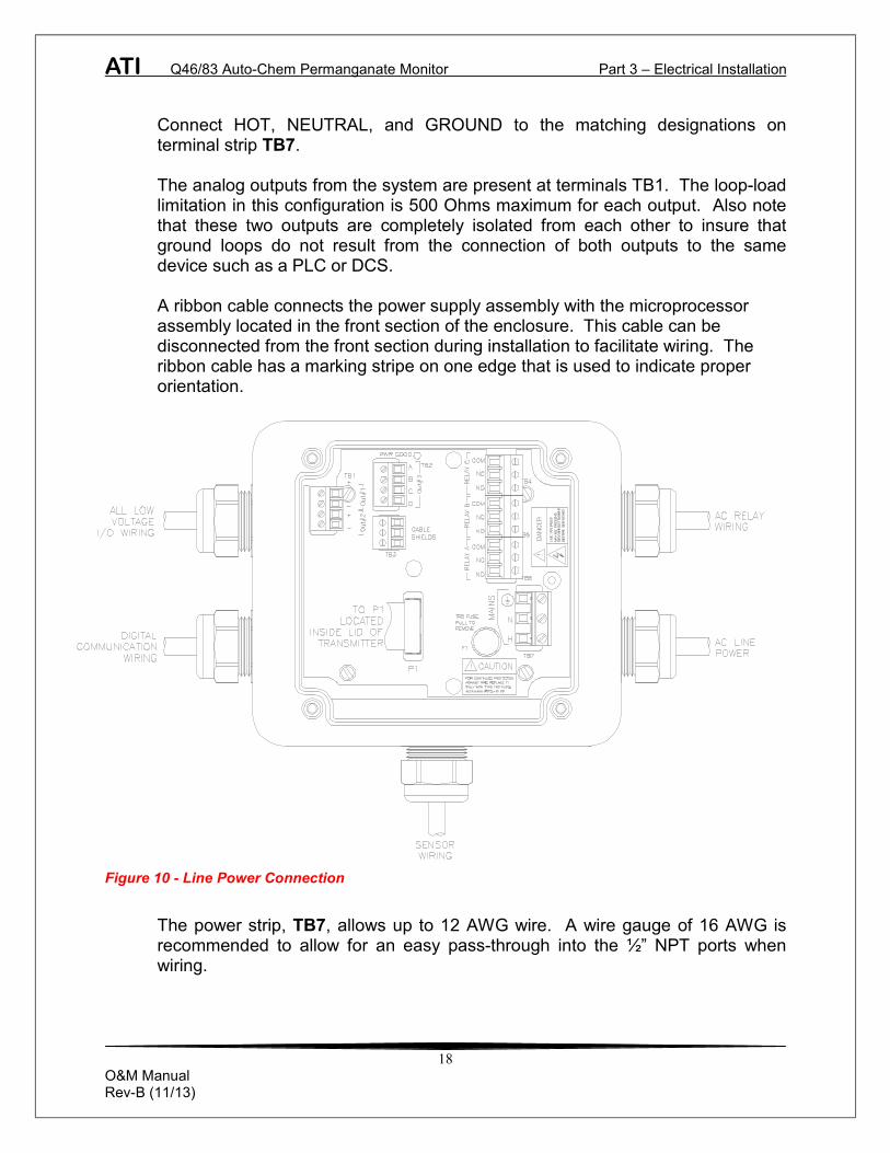
Connect HOT, NEUTRAL, and GROUND to the matching designations on terminal strip TB7. The analog outputs from the system are present at terminals TB1. The loop-load limitation in this configuration is 500 Ohms maximum for each output. Also note that these two outputs are completely isolated from each other to insure that ground loops do not result from the connection of both outputs to the same device such as a PLC or DCS. A ribbon cable connects the power supply assembly with the microprocessor assembly located in the front section of the enclosure. This cable can be disconnected from the front section during installation to facilitate wiring. The ribbon cable has a marking stripe on one edge that is used to indicate proper orientation.
Figure 10 - Line Power Connection
The power strip, TB7, allows up to 12 AWG wire. A wire gauge of 16 AWG is recommended to allow for an easy pass-through into the ½” NPT ports when wiring.

ATI Q46/83 Auto-Chem Permanganate Monitor Part 3 – Electrical Installation
19
O&M Manual Rev-B (11/13)
3.3 Q46/83 Sensor Wiring
The sensor cable can be quickly connected to the Q46 terminal strip by matching the wire colors on the cable to the color designations on the label in the monitor. Route signal cable away from AC power lines, adjustable frequency drives, motors, or other noisy electrical signal lines. Do not run sensor or signal cables in conduit that contains AC power lines or motor leads. Sensor connections are made in accordance with Figure 11. A 20 ft. sensor cable is supplied with the unit. The sensor cable can be routed into the enclosure through one of cord-grips supplied with the unit. The sensor cable can be cut to the length required for a particular installation if desired. Do not cut sensor cable too short, as some loose cable is needed near the installation point to facilitate sensor installation and removal.
Figure 11 - Sensor Connection

ATI Q46/83 Auto-Chem Permanganate Monitor Part 3 – Electrical Installation
20
O&M Manual Rev-B (11/13)
Cord-grips used for sealing the cable should be snugly tightened after electrical connections have been made to prevent moisture incursion. When stripping cables, leave adequate length for connections in the transmitter enclosure as shown below. The standard 20 ft. sensor cable normally supplied with the system is already stripped and ready for wiring. This cable can be cut to a shorter length if desired to remove extra cable in a given installation.
. 3.4 Relay Wiring
Three SPDT relays are provided on the power supply board. None of the relay contacts are powered. The user must supply the proper power to the contacts. For applications that require the same switched operating voltage as the Q46 (115 or 230 V), power may be jumpered from the power input terminals at TB7. Relay wiring is connected at TB4,TB5, and TB6 as shown below. Note that the relay contact markings are shown in the NORMAL mode. Programming a relay for “Failsafe” operation reverses the NO and NC positions in this diagram (Figure 12).
Figure 12 - Relay Contacts

ATI Q46/83 Auto-Chem Permanganate Monitor Part 3 – Electrical Installation
21
O&M Manual Rev-B (11/13)
3.2 Auto-Chem Power Panel
The chemistry module contains terminals and power supplies on a DIN rail located behind the front panel. During installation, it is often convenient to completely remove the front panel, allowing access to terminals inside. To remove the front panel, open the latch at the top of the panel and allow the panel to hinge forward. A retaining strap will stop the panel from moving too far. The two pumps are plugged into the 24 VAC power supply on the right. The cooling fan and sample conditioner element are plugged into the 6 VDC power supply on the left. It is easiest to unplug all 4 items at the power supplies. The RTD temperature element wires have a molex connector that can be unplugged. Also, remove the air line from the lower fitting of the rotameter. Once everything is disconnected, open the Velcro on the retaining strap and slide the strap through the slots on the front panel. At this point, the entire front panel can be removed from the enclosure. Below is a photo of the interior showing power supplies and terminals.
Figure 13 – Auto-Chem Connection Panel

ATI Q46/83 Auto-Chem Permanganate Monitor Part 3 – Electrical Installation
22
O&M Manual Rev-B (11/13)
3.2 Auto-Chem Power Panel Wiring
A 7-conductor shielded cable connects the chemistry module to the Q46 monitor. The chemistry module connections for this cable are done at the factory and 25 ft. length of cable is supplied for routing to the monitor. This cable can be cut to the length required by a particular installation. If cutting cable length, prior to connecting to analyzer, remove the BROWN cond. It is not used. Eliminating excess cable can reduce the potential for electrical interference. When stripping cables, leave adequate lead lengths for connection in the transmitter enclosure. Figure 14 provides detail of the internal connections and the location of the AC power connection for the Auto-Chem Module. Figure 11 shows color coded connection points to the analyzer. Route signal cable away from AC power lines, adjustable frequency drives, motors, or other noisy electrical signal lines. Do not run sensor or signal cables in conduit that contains AC power lines or motor leads.
Analytical Technology, Inc.Analytical Technology, Inc.
Figure 14 - Auto-Chem Customer Wiring

23
O&M Manual Rev-B (11/13)
Part 4 – Auto-Chem Startup 4.1 General
Prior to operating the chemistry module, connect inlet sample and drain tubing to the hose barbs provided on inlet overflow assembly. Remove the clear cover from the chemistry module and check the inlet and outlet tube connections on the inside cover of the overflow assembly. Also, check to be sure that the reagent pickup tube is connected to the inlet fitting of the regent pump. The sensor for the system is installed in the flowcell but is not ready for use when received. The sensor must first be prepared by installing a new membrane and electrolyte. Disconnect the keeper plug and plug the sensor cable into the back of the sensor. Remove the protective cap from the end of the sensor and slide it into the sensor flow block. Plug the keeper into the spare sensor and store it in a convenient place. Storage in a sealed container in a cool location is best.
4.2 Reagent
Q46/83 Permanganate systems require buffer and KI to convert the permanganate ion to iodine. The buffer used in the system is white vinegar (5% acetic acid) available in most supermarkets. If desired, the buffer solution may be prepared by purchasing acetic acid solution from a laboratory supply company and diluting to 5%. One package of potassium iodide (50 grams) is supplied in dry form. Fill the KI solution bottle with distilled water and add the KI. Invert the bottle a few times to insure that the KI is completely dissolved. The reagent pump in the Auto-Chem system pumps the two reagents at a rate of about 0.1 cc/min. A one gallon bottle of reagent will last about 26 days in continuous operation.
4.3 Reagent Pump Priming
Reagent is pulled from the gallon container by a peristaltic pump in the Auto-Chem. It can take up to 20 minutes for reagents to reach the sample injection point when power is first turned on. If desired, the reagent feed tubes can be manually filled to reduce the waiting time.

ATI Q46/83 Auto-Chem Permanganate Monitor Part 4 AutoChem Startup
24
O&M Manual Rev-B (11/13)
A 10 cc syringe with plastic tip is supplied for this purpose. To fill the feed tube, release the pressure on the reagent pump tubes by loosening the clamp plate on the left side of the pump. Then disconnect the 1/16” I.D. tube from the injection tee below the sample pump. Insert the tip of the syringe into the tube and use the syringe to draw reagents from the bottle into the syringe. When reagents have reached the syringe, replace the pressure plate on the reagent pump. Once the pressure plate is properly seated, disconnect the syringe and connect the tubing to the injection tee. Discard the reagent in the syringe and rinse.
Figure 15 – Auto-Chem Panel Components

ATI Q46/83 Auto-Chem Permanganate Monitor Part 4 AutoChem Startup
25
O&M Manual Rev-B (11/13)
4.4 Operation
As noted in the “Electrical Installation” section, the chemistry module contains a lever fuse holder that can be used to turn the chemistry system on and off. Once the steps outlined earlier in this section are complete and power has been connected to the proper terminals, simply close the lever fuse to activate the chemistry module. Once power is applied, the two peristaltic pumps will start to turn and the rotameter on the panel should begin to indicate the air flowrate. Use the air flow control valve to adjust the rotameter to 400 cc. per minute. The air is discharged into the reactor and you will see bubbling in that chamber. The final discharge of the air is into the drain chamber of the inlet overflow assembly, and you should also see bubbling there. Assuming that sample is flowing to the overflow assembly, sample will reach the reactor in just a few seconds. If the reagent feed has been manually primed, the system will begin to function almost immediately. It is best to allow the system to run undisturbed for 1 hour after initial startup. Note that the electronics module should also be powered up at this time. The sensor will not stabilize unless the power to the monitor is turned on.
4.5 Internal Gas & Liquid Flow In the Auto-Chem chemistry module there are two flow paths, one for gas and one for liquid. Understanding how these two flow paths should function will allow you to quickly verify that the system in operating normally. The gas flow is used to strip Iodine gas from the treated sample and carry it to the sensor. An air pump behind the front panel pulls ambient air from inside the enclosure and pumps it through the rotameter and into the Teflon stripping chamber. The air exits the stripping chamber through the chamber plug at the top and flows through the Teflon gas conditioning block where excess moisture is removed. From the conditioning block, the air flows through the sensor chamber and then out through a tube connected to the drain chamber of the inlet overflow at the bottom of the enclosure. During normal operation, bubbling should be observed in both the stripping chamber and in the overflow outlet chamber.

ATI Q46/83 Auto-Chem Permanganate Monitor Part 4 AutoChem Startup
26
O&M Manual Rev-B (11/13)
The liquid flow originates in the inlet chamber of the overflow block. Sample is pulled up from that chamber by vacuum and reagent is injected into the sample just below the sample pump. The treated water is pumped into the stripping chamber where it is stripped of Iodine. The water overflows into the drain side of the stripping chamber where it is pumped out. The water from the drain side is then pumped into the rear chamber of the gas conditioning block and from there it flows to the drain chamber of the overflow assembly. One other liquid flow path exists, but does not carry much flow. One channel of the reagent pump is connected to the bottom of the gas conditioning block and is used to pump condensate out of the block and into the main drain line.
4.6 Sensor Preparation
The iodine gas sensor is shipped with a protective membrane but with no electrolyte inside. A new membrane and electrolyte must be installed in the sensor prior to operation. In addition, the membrane and internal electrolyte need replacement on 2-3 month schedule. Iodine sensors are three part assemblies as shown in Figure 16. Replacement membranes are supplied in boxes of 10 precut disks. The following procedure must be followed exactly to insure proper sensor operation.
Figure 16 - Sensor Assembly

ATI Q46/83 Auto-Chem Permanganate Monitor Part 4 AutoChem Startup
27
O&M Manual Rev-B (11/13)
CRITICAL NOTE: The 05-0074 membrane used on the iodine gas sensor
MUST be installed with the proper side facing the outside. Examine the membrane carefully to identify the “shiny” side. The membrane has a dull side and a shiny side. The shiny side must face out, or be in contact with the gas stream. Reversing the membrane will cause no damage, but the measurement will be very unstable.
Follow the procedure below to prepare the sensor for operation: 1. Unscrew the electrolyte chamber from the body of the sensor. Discard the
electrolyte inside. 2. Unscrew the membrane cap from the end of the electrolyte chamber and
push out and discard the old membrane. 3. From the membrane container, carefully remove a white disc and place it in
the membrane cap. Be sure that the shiny side of the membrane is facing down when putting it into the cap. Handle membranes only with clean hands. Place the membrane into the cap and carefully push it down so that it lies flat in the bottom of the cap.
4. Check the end of the electrolyte chamber to be sure the o-ring is seated
properly. Then screw the membrane cap onto the electrolyte chamber. Pour electrolyte into the chamber until the level is about ¼” from the top.
5. Slowly screw the electrolyte chamber onto the sensor body. A small amount
of electrolyte will run out the top, so it’s best to do this over a sink.
6. Wipe excess electrolyte from the sides of the sensor, insert it into the flow chamber on the side of the reactor, and plug the sensor cable into the back.
CAUTION: The electrolyte used in this sensor will not harm your skin, but
should be rinsed off after the sensor is assembled. Do not get electrolyte in your eyes as it will cause stinging. If eye contact occurs, flush with large amounts of water. Electrolyte can cause discoloration of clothing, so avoid getting the liquid on your garments.

28
O&M Manual Rev-B (11/13)
Part 5 – Configuration 5.1 User Interface
The user interface for the Q46 Series instrument consists of a custom display and a membrane keypad. All functions are accessed from this user interface (no internal jumpers, pots, etc.).
Figure 17 - User Interface
MENU ICONS
UNITS
12-CHARACTERSECONDARY
DISPLAY
MEMBRANEKEYPAD
MENUESC
ENTER
A
B
DIAGFAILHOLD
CALCONF
MENU ICONS
UNITS
12-CHARACTERSECONDARY
DISPLAY
MEMBRANEKEYPAD
ENTER KEY
LEFT ARROWKEY
4-DIGITMAIN DISPLAY
MENU/ESCAPEKEY
UP ARROWKEY
SIGN
RELAY/LO-BATINDICATOR
4-KEY USERINTERFACE
RELAYINDICATOR

ATI Q46/83 Auto-Chem Permanganate Monitor Part 5 – Configuration
29
O&M Manual Rev-B (11/13)
5.11 Keys All user configurations occur through the use of four membrane keys. These keys are used as follows:
MENU/ESC To scroll through the menu section headers or to escape from anywhere in software. The escape sequence allows the user to back out of any changes in a logical manner. Using the escape key aborts all changes to the current screen and backs the user out one level in the software tree. The manual will refer to this key as either MENU or ESC, depending upon its particular function.
UP (arrow) To scroll through individual list or display items and to
change number values. LEFT (arrow) To move the cursor from right to left during changes to a
number value. ENTER To select a menu section or list item for change and to store
any change. 5.12 Display
The large custom display provides clear information for general measurement use and user configuration. There are three main areas of the display: the main parameter display, the secondary message line, and the icon area.
Main Parameter During normal operation, the main parameter display
indicates the present process input with sign and units. This main display may be configured to display any of the main measurements that the system provides. During configuration, this area displays other useful set-up information to the user.

ATI Q46/83 Auto-Chem Permanganate Monitor Part 5 – Configuration
30
O&M Manual Rev-B (11/13)
Lower Line During normal operation, the lower line of the display
indicates user-selected secondary measurements that the system is making. This also includes calibration data from the last calibration sequence and the transmitter model number and software version. During configuration, the lower line displays menu items and set-up prompts to the user. Finally, the lower line will display error messages when necessary. For a description of all display messages, refer to Section 9.4.
Icon Area The icon area contains display icons that assist the user in
set-up and indicate important states of system functions. The CAL, CONFIG, and DIAG icons are used to tell the user what branch of the software tree the user is in while scrolling through the menu items. This improves software map navigation dramatically. Upon entry into a menu, the title is displayed (such as CAL), and then the title disappears to make way for the actual menu item. However, the icon stays on.
HOLD The HOLD icon indicates that the current output of the
transmitter has been put into output hold. In this case, the output is locked to the last input value measured when the HOLD function was entered. HOLD values are retained even if the unit power is cycled.
FAIL The FAIL icon indicates that the system diagnostic function
has detected a problem that requires immediate attention. This icon is automatically cleared once the problem has been resolved.
32.0 nA

ATI Q46/83 Auto-Chem Permanganate Monitor Part 5 – Configuration
31
O&M Manual Rev-B (11/13)
Relay Area A/B The relay area contains two icons that indicate the state of
the system relays (if the relay card is installed). If the battery board is installed instead, the B icon indicates that the battery voltage is at a low level. The battery power option and the relay option cannot be installed together.
5.2 Software
The software of the Q46 is organized in an easy to follow menu-based system. All user settings are organized under five menu sections: Measure, Calibration [CAL], Configuration [CONFIG], Control [CONTROL] and Diagnostics [DIAG]. Note: The default Measure Menu is display-only and has no menu icon.
5.21 Software Navigation
Within the CAL, CONFIG, CONTROL, and DIAG menu sections is a list of selectable items. Once a menu section (such as CONFIG) has been selected with the MENU key, the user can access the item list in this section by pressing either the ENTER key or the UP arrow key. The list items can then be scrolled through using the UP arrow key. Once the last item is reached, the list wraps around and the first list item is shown again. The items in the menu sections are organized such that more frequently used functions are first, while more permanent function settings are later in the list. See Figure 18 for a visual description of the software.
Each list item allows a change to a stored system variable. List items are designed in one of two forms: simple single variable, or multiple variable sequences. In the single variable format, the user can quickly modify one parameter - for example, changing the display range from 2.000 to 20.00. In the multiple variable sequence, variables are changed as the result of some process. For example, the calibration of permanganate generally requires more than one piece of information to be entered. The majority of the menu items in the software consist of the single variable format type.

ATI Q46/83 Auto-Chem Permanganate Monitor Part 5 – Configuration
32
O&M Manual Rev-B (11/13)
Any data that may be changed will be flashing. This flashing indicates user entry mode and is initiated by pressing the ENTER key. The UP arrow key will increase a flashing digit from 0 to 9. The LEFT arrow key moves the flashing digit from right to left. Once the change has been completed, pressing ENTER again stores the variable and stops the flashing. Pressing ESC aborts the change and also exits user entry mode. The starting (default) screen is always the Measure Menu. The UP arrow key is used to select the desired display. From anywhere in this section the user can press the MENU key to select one of the four Menu Sections. The UP arrow icon next to all list items on the display is a reminder to scroll through the list using the UP arrow key. To select a list item for modification, first select the proper menu with the MENU key. Scroll to the list item with the UP arrow key and then press the ENTER key. This tells the system that the user wishes to perform a change on that item. For single item type screens, once the user presses the ENTER key, part or all of the variable will begin to flash, indicating that the user may modify that variable using the arrow keys. However, if the instrument is locked, the transmitter will display the message Locked! and will not enter user entry mode. The instrument must be unlocked by entering the proper code value to allow authorized changes to user entered values. Once the variable has been reset, pressing the ENTER key again causes the change to be stored and the flashing to stop. The message Accepted! will be displayed if the change is within pre-defined variable limits. If the user decides not to modify the value after it has already been partially changed, pressing the ESC key aborts the modification and returns the entry to its original stored value. In a menu item which is a multiple variable sequence type, once the ENTER key is pressed there may be several prompts and sequences that are run to complete the modification. The ESC key can always be used to abort the sequence without changing any stored variables.

ATI Q46/83 Auto-Chem Permanganate Monitor Part 5 – Configuration
33
O&M Manual Rev-B (11/13)
Start
MEASURE(display only)
CAL CONFIG DIAG
ENTER
MENUESC
or or or
Cal KMnO4 1PID 0% #1 Set Hold
1PID 100% #1
1PID Setpoint #1
1PID Prop #1
Fault List
Sim Out
Fail Out #1
Fail Val #1
Fail Out #2
Offset
Temperature
1PID % Output
Loop Current (#1)
LISTITEMS
Cal Temp
Loop Current (#2)
Set Default
2 Loop Current (#3)
CONTROL
Fail Val #2
Failsafe
1PID Int #1
1PID Deriv #1
Set 4mA (#1)
Set 20mA (#1)
or
Entry Lock
Set Delay
Contrast
Main Display
I out 1 Mode
I out 2 Mode
Relay B Mode
Temp Units
Set 4mA (#2)
Set 20mA (#2)
nA
5Aux rly=
1PID Timer
Set Range
MENUSECTIONS
Software Version
Main Units
Zero Filter
Slope
MENUESC
ENTER
MENUESC
MENUESC
MENUESC
ENTER ENTER
Relay A Mode
2 I out 3 Mode
Relay C Mode
4 Com Mode
4 Com Address
2Set 4mA (#3)
2 Set 20mA (#3)
3 Setpnt A (or A-HI, A-LO)
3 Hyst A (or A-HI, A-LO)
3 Delay A (or A-HI, A-LO)
Phase A
Setpnt B
Hyst B
Delay B
Phase B
Setpnt C
Hyst C
Delay C
Phase C
2Fail Out #3
2Fail Val #3
Backlight
Notes:(1) If Relay A,B,C, is set to FAIL mode, relay settings are not displayed in menu.(2) The annunciator for Relay C is shown in the MEASURE/ temperature display
PID is enabled1
Optional third 4-20 output installed2
If Relay A is set to ALARM mode, the settings are divided into3
2 groups of HI and LO points.7 If Comm Mode is set to a selection other than none, additional Comm menus will show.
Start Delay
Figure 18 - Software Map

ATI Q46/83 Auto-Chem Permanganate Monitor Part 5 – Configuration
34
O&M Manual Rev-B (11/13)
5.22 Measure Menu [MEASURE]
The default menu for the system is the display-only menu MEASURE. This menu is a display-only measurement menu, and has no changeable list items. When left alone, the instrument will automatically return to this menu after approximately 30 minutes. While in the default menu, the UP arrow allows the user to scroll through the secondary variables on the lower line of the display. A brief description of the fields in the basic transmitter version is as follows:
ANALYZER MEASURE SCREENS:
25.7C Temperature display. Can be displayed in °C or °F,
depending on user selection. A small “m” on the left side of the screen indicates the transmitter has automatically jumped to a manual 25C setting due to a failure with the temperature signal input.
32.0 nA Raw sensor current. Useful for diagnosing problems. 100% 20.00 mA PID Status screen (if enabled.) Shows the present controller
output level on left, and actual transmitter current on the right. The controller can be placed in manual while viewing this screen by pressing and holding the ENTER key for 5 seconds until a small flashing “m” appears on the screen. At that point the controller output can be adjusted up or down using the UP and LEFT arrow keys. To return to automatic operation, press and hold the ENTER key for 5 seconds and the “M” will disappear.
4.00 mA Transmitter output current # 1 20.00 mA Transmitter output current # 2 #3 20.00 mA Analyzer output current # 3 (if option included.) Slope = 100% Sensor output response vs. ideal calibration. This value
updates after each calibration. As the sensor ages, the slope reading will decay indicating sensor aging. Useful for resolving sensor problems.
Offset = 0.0 nA Sensor output current at a zero ppm input. This value
updates after a zero-calibration has been performed. Useful for resolving sensor problems.

ATI Q46/83 Auto-Chem Permanganate Monitor Part 5 – Configuration
35
O&M Manual Rev-B (11/13)
Q46H0 VX.XX Transmitter software version number. Note: A display test (all segments ON) can be actuated by pressing and
holding the ENTER key while viewing the model/version number on the lower line of the display.
The MEASURE screens are intended to be used as a very quick means of looking up critical values during operation or troubleshooting.
5.23 Calibration Menu [CAL]
The calibration menu contains items for frequent calibration of user parameters. There are three items in this list: Cal KMnO4, Cal Temp. and Set Range.
Cal Allows the user to adjust the transmitter span reading to
match a reference solution, or to set the sensor zero point. See Part 6 - Calibration for more details.
Cal Temp Allows the user to adjust the offset of the temperature
response by a small factor of ±5 °C. The temperature input is factory calibrated. Long cable lengths and junction boxes may degrade the accuracy in some extreme situations. See Part 6 - Calibration for more details.
Set Range Provides for user selection of the display range. Once set,
all output functions use this display range to establish configuration settings. Press ENTER to initiate user entry mode, and the value will flash. Use the arrow keys to modify value; available ranges include 2.000 ppm, 20.00 ppm, and 200.0 ppm. Press ENTER to store the new value.
5.24 Configuration Menu [CONFIG] The Configuration Menu contains all of the general user settings: Entry Lock Used to inhibit unauthorized tampering with instrument
settings. All settings may be viewed while the instrument is locked, but cannot be modified. The Entry Lock is a toggle-type setting; that is, entering the correct code will lock the transmitter and entering the correct code again will unlock it. The code is preset at a fixed value. Press ENTER to initiate user entry mode and the first digit will flash. Use arrow keys to modify value. See Page 63 for the Q46S lock/unlock code. Press ENTER to toggle lock setting once code is correct.

ATI Q46/83 Auto-Chem Permanganate Monitor Part 5 – Configuration
36
O&M Manual Rev-B (11/13)
Set Delay Sets the amount of damping on the instrument. Both the
display and the output value are affected by the degree of damping. Functions such as calibration are not affected by this parameter. The calibration routines contain their own filtering and stability monitoring functions to minimize the calibration timing. Press ENTER to initiate user entry mode, and the value will flash. Use the arrow keys to modify value; range is 0.2 to 9.9 minutes. Press ENTER to store the new value. Default is 0.2.
Contrast Sets the contrast level for the display. The STN display
provides the highest possible contrast and widest viewing angle under all conditions. Contrast control will rarely be adjusted, but extreme operating conditions could result in the need for a small change. Press ENTER to initiate user entry mode, and the value will flash. Use arrow keys to modify the value; range is 0 to 8 (0 being lightest). Press ENTER to update and store the new value. Default is 8.
Main Units This function allows the user to select either PPM or mg/l.
Default is PPM. Zero Filter This function forces the reading to zero when reading is
below the entered value. For example, if the entered value were 0.0020 the display at 0-0019 would indicate 0.000. This feature is useful in blanking out zero noise. Default is 0.
Main Display Allows the user to change the primary display. The selection
is either sulfite concentration or output current. Press ENTER and the display will flash. Use the UP arrow key to modify the desired display value. Press ENTER to store the new value. Default is Permanganate concentration.
Com Mode Sets digital communication mode. A digital communication
card must be plugged into the power supply slot for this function to work. Press ENTER and display will flash. Use the UP arrow key to modify the desired value; selections include 1-None, 2- P-DP for Profibus DP, 3 - Modbus. Press ENTER to store the new value. Default depends on whether a communication board was ordered.
Com Address Sets bus address for digital communication. Press ENTER
and the display will flash. Use the UP arrow key to modify the desired value. Range is 1-125. Press ENTER to store the value.

ATI Q46/83 Auto-Chem Permanganate Monitor Part 5 – Configuration
37
O&M Manual Rev-B (11/13)
Iout#1 Mode Sets analog output #1 for either sulfide concentration or PID
control. Press ENTER and the display will flash. Use the UP arrow key to select. Selections include 1-ppm for sulfite concentration or 2-PID control. Press ENTER to store the new value. Default is 1-KMno4.
Iout#2 Mode Sets analog output #2 for either temperature or sulfide.
Press ENTER and the display will flash. Use the UP arrow key to select. Selections include: 1-°C for temperature, or 2-PPM for sulfite. Press ENTER to store the new value. Default is 1-°C.
Iout#3 Mode OPTIONAL. This function sets analog output #3 for
temperature (default) or permanganate. Press ENTER to initiate user entry mode, and the entire value will flash. Use the UP arrow key to modify the desired value; selections include 1-C/F for temperature, 2-ppm for KMnO4. Press ENTER to store the new value.
Rly A Mode Relay A can be used in three different ways: as a setpoint
control, as a fail alarm, or as a HI-LO alarm band. The three settings for Rly A Mode are CON, FAIL and AL.
The CON setting enables normal control operation for Relay
A, with settings for setpoint, hysteresis, delay and phasing appearing in the CONFIG menu automatically. See Figure 19 for further details.
The FAIL setting enables the fail alarm mode for Relay A.
Relay A will then trip on any condition that causes the FAIL icon to be displayed on the LCD. Using this mode allows the User to send alarm indications to other remote devices.
The AL setting allows two setpoints to be selected for the
same relay, producing a HI-LO alarm band. In this mode, Relay A will trip inside or outside of the band, depending upon the Phase selected. See Figure 20 for further details.

ATI Q46/83 Auto-Chem Permanganate Monitor Part 5 – Configuration
38
O&M Manual Rev-B (11/13)
Relay B Mode
Relay C Mode Relay B and C can be used in two ways: as a setpoint control, or as an alarm. The two settings for Relay B Mode are CON and FAIL.
The CON setting enables normal setpoint operation for
Relay B/C. Relay B/C then operates identically to Relay A, with settings for setpoint, hysteresis, delay and phasing appearing in the CONFIG menu automatically. See Error! Reference source not found. for details.
The FAIL setting enables the fail alarm mode for Relay B/C.
Relay B/C will then trip on any condition that causes the FAIL icon to be displayed on the LCD. Note that the Relay C indicator shows up only on the lower screen of the display next to the temperature reading. This is because the default setting for relay C is the FAIL setting. Using this mode allows the User to send alarm indications to other remote devices.
5.25 Control Menu [CONTROL] The Control Menu contains all of the output control user settings: Set 4 mA Set 20 mA [Iout1=PPM] Allows adjustment of analog output #1. The units displayed
depend on the selection made in the CONFIG menu for Iout #1 Mode.
The value stored for the 4 mA point may be higher or lower
than the value stored for the 20 mA point. The entry values are limited to values within the range specified in “Set Range”, and the 4 mA and the 20 mA point must be separated by at least 1% of this range Use the LEFT arrow key to select the first digit to be modified. Then use the UP and LEFT arrow keys to select the desired numerical value. Press ENTER to store the new value.

ATI Q46/83 Auto-Chem Permanganate Monitor Part 5 – Configuration
39
O&M Manual Rev-B (11/13)
Set PID 0% Set PID 100% [Iout1=PID] If the PID is enabled, this function sets the minimum and
maximum controller end points. Unlike the standard 4-20 mA output, the controller does not “scale” output values across the endpoints. Rather, the endpoints determine where the controller would normally force minimum or maximum output in an attempt to recover the setpoint (even though the controller can achieve 0% or 100% anywhere within the range.)
If the 0% point is lower than the 100% point, then the
controller action will be “reverse” acting. That is, the output of the controller will increase if the measured value is less than the setpoint, and the output will decrease if the measured value is larger than the setpoint. Flipping the stored values in these points will reverse the action of the controller to “direct” mode.
The entry value is limited to a value within the range
specified in “Set Range”, and the 0% and the 100% point must be separated by at least 1% of this range Use the LEFT arrow key to select the first digit to be modified. Then use the UP and LEFT arrow keys to select the desired numerical value. Press ENTER to store the new value.
PID Setpnt [Iout1=PID] The value which the controller is attempting to maintain by
adjusting output value. PID Prop [Iout1=PID] Proportional gain factor. The proportional gain value is a
multiplier on the controller error (difference between measured value and setpoint value.) Increasing this value will make the controller more responsive.
PID Int [Iout1=PID] Integral is the number of “repeats-per-minute” of the action
of the controller. It is the number of times per minute that the controller acts on the input error. At a setting of 2.0 rpm, there are two repeats every minute. If the integral is set to zero, a fixed offset value is added to the controller (manual reset.) Increasing this value will make the controller more responsive.

ATI Q46/83 Auto-Chem Permanganate Monitor Part 5 – Configuration
40
O&M Manual Rev-B (11/13)
PID Deriv [Iout1=PID] Derivative is a second order implementation of Integral, used
to suppress “second-order” effects from process variables. These variables may include items like pumps or mixers that may have minor impacts on the measured value. The derivative factor is rarely used in water treatment process, and therefore, it is best in most cases to leave it at the default value. Increasing this value will make the controller more responsive.
Set 4 mA #2 Set 20 mA #2 [Temp / PPM] Sets the span of analog output #2. The default setting for
this output is temperature, but it may be set for PPM if preferred. The values stored for the 4 mA point may be higher or lower than the value stored for the 20 mA point.
The entry value is limited to a value between 0 and 55 °C if it
is set for temperature. The 4 mA and the 20 mA point must be at least 20 units away from each other. Press ENTER and the display will flash. Use arrow keys to modify value. Press ENTER to store the new value.
. Set 4 mA #3 Set 20 mA #3 [temp/chlor/pH] OPTIONAL These functions set the optional third 4 mA and
20 mA current loop output points for the analyzer. The output may be set to track temperature (default), pH, or chlorine. The values stored for the 4 mA point may be higher or lower than the value stored for the 20 mA point.
The entry value is limited to a value between 0 and 55 °C if it
is set for temperature and within the range specified in “Set Range” if the output is set to track permanganate. The 4 mA and the 20 mA point must be at least 20 units away from each other. Press ENTER to initiate user entry mode, and the value will flash. Use arrow keys to modify value. Press ENTER to store the new value.
A Setpoint Programs the setpoint for relay A. The entry value is limited
to a value within the range specified in “Set Range”. Use the LEFT arrow key to select the first digit to be modified. Then use the UP and LEFT arrow keys to select the desired numerical value. Press ENTER to store the new value

ATI Q46/83 Auto-Chem Permanganate Monitor Part 5 – Configuration
41
O&M Manual Rev-B (11/13)
A Hysteresis Programs the hysteresis or “deadband” for Relay A.
Hysteresis is most often used to control relay chattering; however, it may also be used in control schemes to separate the ON/OFF trip points of the relay. Press ENTER and the display will flash. Use the arrow keys to modify value. Press ENTER to store the new value.
A Delay Programs the amount of time delay on the trip point for relay
A. The entry value is limited to a value between 0 and 999 seconds. Press ENTER and the display will flash. Use arrow keys to modify value; range is 0 to 999 seconds. Press ENTER to store the new value.
A Phasing Establishes the direction of the relay trip. When phase is HI,
the relay activates when the measured value exceeds setpoint A. When the phase is LO, the relay energizes and the LCD indicator illuminates when the measured value drops below the setpoint.
The failsafe setting does have an impact on this logic. The
description here assumes the failsafe setting is OFF. Press ENTER and the display will flash. Use the UP arrow key to select either HI for direct operation or LO for reverse operation. Press ENTER to store the new value
See Figure 19 below for a visual description of a typical control relay application.
Figure 19 - Control Relay Example
Setpoint: 1.000 ppm Hyst: 0.050 Delay: 000 Failsafe: OFF
When value rises to ≥ 1.000 ppm, relay closes.
When value falls to ≤ 0.950 ppm, relay opens.
When value rises to ≥ 1.050 ppm, relay opens.
When value falls to ≤ 1.000 ppm, relay closes.
Settings:
}1.000 ppm
0.950 ppmPHASE: HI
ON
HYSTERESISOR
“DEAD BAND”
X
OFF
}1.050 ppm
1.000 ppmPHASE: LO
OFF
HYSTERESISOR
“DEAD BAND”XON

ATI Q46/83 Auto-Chem Permanganate Monitor Part 5 – Configuration
42
O&M Manual Rev-B (11/13)
If Relay A Mode is set to Alarm Mode, AL, then the following
settings will appear in the Config Menu list automatically. In this mode, two setpoints can be selected on the same relay, to create an alarm band. Phase HI selection causes the relay to energize outside of the band, and Phase LO causes the relay to energize inside of the band. This feature enables one relay to be used as a control relay while the other is used as a HI-LO Alarm relay at the same time. Setpoint A-LO must be set lower than Setpoint A-HI. When AL mode is first selected, Setpoint A-LO is defaulted to 0.
Figure 20 is a visual description of a typical alarm relay application.
Figure 20 - Alarm Relay Example
If Relay B Mode is set to CON (see Relay B Mode), then Relay B will function identically to Relay A. Relay B settings appear in the CONFIG menu list automatically
Setpoint A-HI: 1.000 ppm Setpoint A-LO: .500 ppm Hyst A-HI: 0.050 Hyst A-LO: .0.050 Delay A-HI: 000 Delay A-LO: 000
When value rises to ≥ 1.000 ppm, relay closes, until value falls back to < 0.950 ppm.
Settings:
When value falls to < 0.500 ppm, relay closes, until rises back to > 0.550 ppm.
When value rises to ≥ 0.500 ppm, relay closes, until value falls back to < 0.450 ppm.
When value falls to < 1.000 ppm, relay closes, until rises back to > 1.050 ppm.
*Setpnt A-HI *Hyst A-HI *Delay A-HI *Setpnt A-LO *Hyst A-LO *Delay A-LO
*B Setpoint *B Hysteresis *B Delay *B Phasing
}
}
1.000 ppm0.950 ppm
0.550 ppm0.500 ppm
PHASE: HI
ON
HYST - HI
HYST - LO
ON
X
X
OFF
}
}
1.050 ppm1.000 ppm
0.500 ppm0.450 ppm
PHASE: LO
OFF
HYST - HI
HYST - LO
OFF
X
X
ON

ATI Q46/83 Auto-Chem Permanganate Monitor Part 5 – Configuration
43
O&M Manual Rev-B (11/13)
If Relay C Mode is set to CON (see Relay C Mode), then Relay C will function identically to Relay A. Relay C settings appear in the CONFIG menu list automatically.
5.26 Diagnostics Menu [DIAG]
The diagnostics menu contains all of the user settings that are specific to the system diagnostic functions, as well as functions that aid in troubleshooting application problems.
Set Hold Locks the analog output values on the present value and
halts operation of the PID controller. This function can be used prior to calibration, or when removing the sensor from the process to hold the output. Once HOLD is released, the outputs return to their normal function. The transfer out of HOLD is bumpless on both analog outputs - that is, the transfer occurs in a smooth manner rather than as an abrupt change. An icon on the display indicates the HOLD state, and the HOLD state is retained even if power is cycled. Press ENTER and the display will flash. Use the UP arrow key to select. Selections are ON for engaging the HOLD function, and OFF to disengage the function. Press ENTER to store the new value.
The Set Hold function can also hold at an output value
specified by the user. To customize the hold value, first turn the HOLD function on. Press the ESC key to go to the DIAG Menu and scroll to Sim Output using the UP arrow key. Press ENTER. Follow the instructions under Sim Output (see following page).
Fault List The Fault List screen is a read-only screen that allows the
user to display the cause of the highest priority failure. The screen indicates the number of faults present in the system and a message detailing the highest priority fault present. Note that some faults can result in multiple displayed failures due to the high number of internal tests occurring. As faults are corrected, they are immediately cleared.
*C Setpoint *C Hysteresis *C Delay *C Phasing

ATI Q46/83 Auto-Chem Permanganate Monitor Part 5 – Configuration
44
O&M Manual Rev-B (11/13)
Faults are not stored; therefore, they are immediately
removed if power is cycled. If the problem causing the faults still exists, however, faults will be displayed again after power is re-applied and a period of time elapses during which the diagnostic system re-detects them. The exception to this rule is the calibration failure. When a calibration fails, no corrupt data is stored. Therefore, the system continues to function normally on the data that was present before the calibration was attempted.
After 30 minutes or if power to the transmitter is cycled, the
failure for calibration will be cleared until calibration is attempted again. If the problem still exists, the calibration failure will re-occur. Press ENTER to initiate view of the highest priority failure. The display will automatically return to normal after a few seconds.
Sim Out The Sim Out function allows the user to simulate the Permanganate level of the instrument in the user selected display range. The user enters a ppm value directly onto the screen, and the output responds as if it were actually receiving the signal from the sensor. This allows the user to check the function of attached monitoring equipment during set-up or troubleshooting. Escaping this screen returns the unit to normal operation. Press ENTER to initiate the user entry mode, and the right-most digit of the value will flash. Use arrow keys to modify desired value.
PID Timer This function sets a timer to monitor the amount of time the
PID controller remains at 0% or 100%. This function only appears if the PID controller is enabled. If the timer is set to 0000, the feature is effectively disabled. If the timer value is set to any number other zero, a FAIL condition will occur if the PID controller remains at 0% or 100% for the timer value. If one of the relays is set to FAIL mode, this failure condition can be signaled by a changing relay contact.
Press ENTER to initiate user entry mode, and the entire
value will flash. Use the UP arrow key to modify desired value; range of value is 0-9999 seconds. Press ENTER to store the new value.

ATI Q46/83 Auto-Chem Permanganate Monitor Part 5 – Configuration
45
O&M Manual Rev-B (11/13)
Fail Out #1 Enables the user to define a specified value that the main
current output will go to under fault conditions. When enabled to ON, the output may be forced to the current value set in Fail Val (next item.) With the Fail Out setting of ON, and a Fail Val setting of 6.5 mA, any alarm condition will cause the current loop output to drop outside the normal operating range to exactly 6.5 mA, indicating a system failure that requires attention.
Press ENTER to initiate user entry mode, and the entire
value will flash. Use the UP arrow key to modify desired value; selections are ON, OFF. Press ENTER to store the new value.
Fail Val #1 Sets the output failure value for Iout#1. When Fail Out
above is set to ON, this function sets value of the current loop under a FAIL condition. When the Relay Option Board is installed, the display will read Fail Out #1. The output may be forced to any current value between 4-20 mA.
Press ENTER to initiate user entry mode, and the entire
value will flash. Use the UP arrow key to modify desired value; selections are between 4mA, and 20mA. Press ENTER to store the new value.
Fail Out #2 This function sets the fail-mode of current loop output #2
under a FAIL condition. The settings and operation are identical to Fail Out for output #1.
Fail Val #2 This function sets the value of current loop output #2 under a
FAIL condition. The settings and operation are identical to Fail Out for output #1.
Fail Out #3 OPTIONAL. This function sets the fail-mode of current loop output #3 under a FAIL condition. The settings and
operation are identical to Fail Out for output #1.
Fail Val #3 OPTIONAL. This function sets the value of current loop output #3 under a FAIL condition. The settings and operation are identical to Fail Out for output #1.
Backlight Selects the function of the LCD backlight. There are three
options. ON – On all the time, OFF – Off all the time, AL – Alarm (Default). This function flashes the backlight on and off whenever the Fail icon is displayed.

ATI Q46/83 Auto-Chem Permanganate Monitor Part 5 – Configuration
46
O&M Manual Rev-B (11/13)
Failsafe Allows the user to set the relays to a failsafe condition. In a
failsafe condition, the relay logic is reversed so that the relay coil is electrically energized in a normal operating state. By doing this, the relay will not only change state when the concentration limit is exceeded, but also when power is lost to the controller.
Start Delay Minimizes control or alarm issues arising from temporary
power loss. On power outage, the monitor records analog output values and relay status. When power is restored, the analog values and relays will be held at the pre-power loss values for a defined period of time. This “start delay” may be programmed for periods from 0-9.9 minutes.
Set Default Allows the user to return the instrument to factory default
data for all user settings (All) or for just the calibration default (Cal). It is intended as a last resort troubleshooting procedure. All user settings or the calibration settings are returned to the original factory values. Hidden factory calibration data remains unchanged. Press ENTER to initiate user entry mode and select either All or CAL with the UP arrow key.
.

47
O&M Manual Rev-B (11/13)
Part 6 – Calibration 6.1 Calibration
After the chemistry module has been running for a few hours, the system should be zeroed using distilled water. To do this, disconnect the sample pickup line from the inlet overflow and connect the extension tube (supplied with the system). The extension tube is long enough to place into a bottle of distilled water placed near the unit.
6.11 Zero Cal
Allow the system to run for about 30 minutes on distilled water. By the end of that time, the sensor output should be at its lowest value. On the bottom line of the display, you can see the actual sensor current if desired. This is the “nA” display. If you watch that display, you should see a current value that is normally below 10 nA. The value may be changing some up and down, but will not be trending in any one direction. If you look at the large numerical PPM display, you will normally see a value below 0.05 PPM. Iodine sensors have very low offset currents at zero. In some cases, it is sufficient to simply leave the zero at the factory default of 0.0 nA. If measurements are being made that are normally above 0.5 PPM, leaving the unit at electronic zero is satisfactory. If the units is to be used for low level measurements, zeroing the sensor should be done at startup. An electronic zero can be set by disconnecting the sensor from the cable and performing steps 1-3 below. The steps below assume that the system has been operating on distilled water for 30 minutes after the initial 4 hour stabilization time. 1. Scroll to the CAL menu section using the MENU key and press ENTER or the
UP arrow key. Cal KmnO4 will be displayed. 2. Press the ENTER key. The screen will display a flashing 1-Ref for span
calibration or a 2-Zer for zero calibration. Using the UP arrow key, set for a 2-Zer zero calibration and press ENTER.

ATI Q46/83 Auto-Chem Permanganate Monitor Part 6 – Calibration
48
O&M Manual Rev-B (11/13)
The system now begins acquiring data for the sensor zero calibration value. As data is gathered, the units for sensor current in nanoamps (nA) will be displayed. Once the software has identified a stable value, the zero offset current will automatically be recorded. If you don’t wish to wait for the monitor to analyze the data, you can override by pressing ENTER. If the data remains unstable for 10 minutes, the calibration will fail and the message Cal Unstable will be displayed.
3. If accepted, the screen will display the message PASS with the new sensor
zero reading (offset), then it will return to the main measurement display. If the calibration fails, a message indicating the cause of the failure will be displayed and the FAIL icon will be turned on. The range of acceptable value for sensor offset is -25 to +25 nA. Should a FAIL occur, carefully inspect the sensor for membrane fouling. Should the offset value remain high and result in calibration failures, review the Service section of this manual, and then contact the service dept. at ATI for further assistance.
The sensor zero offset value in nA from the last zero calibration is displayed on the lower line of the Default Menus for information purposes.
6.12 Span Cal
Calibration of the Permanganate Monitor can be done in one of two ways. If an accurate laboratory measurement can be made on the same sample that the sensor is measuring, the monitor can be adjusted to the laboratory result. A permanganate standard can also be prepared in accordance with the procedure on the following page. If a lab test is to be done for calibration, the sample should be collected from the inlet chamber of the analyzer. On the bottom of the inlet chamber is a luer fitting with a cap. A small 2-way valve is supplied in your accessory kit for attachment to the luer fitting. Remove the luer cap from the fitting and connect the vave. You can leave this valve in place for convenience or remove it after use. With sample running, simply open the 2-way valve and collect enough sample for the lab test. Close the valve to return to normal operation. The sample should be analyzed as quickly as possible to avoid permanganate loss. When calibrating, it is best to have a reasonably high concentration of KMnO4 in the system. The higher the value, the smaller will be the calibration errors caused by errors in the laboratory analytical procedure. It is generally preferable to calibrate at values above 0.5 PPM to reduce calibration errors.

ATI Q46/83 Auto-Chem Permanganate Monitor Part 6 – Calibration
49
O&M Manual Rev-B (11/13)
To calibrate the system, follow the procedure below. 1. If a mixed standard is to be used, place the sample pickup tube into the
container of standard. If you plan to us actual sample, collect the sample as described previously.
2. Allow either the known sample or mixed sample flow for 5 minutes. 3. Scroll to the CAL menu section using the MENU key and press ENTER or the
UP arrow key. Cal KmnO4 is displayed. 4. Press the ENTER key. The screen will display a flashing 1-Ref for span
calibration or a 2-Zer for zero calibration. Using the UP arrow key, set for a 1-Ref span calibration and press ENTER.
5. The system now begins acquiring data for the calibration value. As data is
gathered, the units for ppm may flash. Flashing units indicate that this parameter is unstable. The calibration data point acquisition will stop only when the data remains stable for a pre-determined amount of time. This can be overridden by pressing ENTER. If the data remains unstable for 10 minutes, the calibration will fail and the message Cal Unstable will be displayed.
6. If stable, the screen will display the last measured ppm value and a message
will be displayed prompting the user to adjust the value. Enter the sample or standard value depending on what you are using. Each digit must be adjusted separately using the á key. Move to the left using the ß key. When adjusted, press Enter.
7. If accepted, the screen will display the message PASS with the new sensor
slope reading. It will return to the main measurement display. If the calibration fails, a message indicating the cause of the failure will be displayed and the FAIL icon will be turned on. The range of acceptable values for sensor slope is 25% to 500%.
6.13 Mixing a Permanganate Standard
It is possible to mix potassium permanganate standards for calibration if you have a high quality analytical balance and a supply of reagent grade potassium permanganate. Dissolve exactly 1 gram of KMnO4 in 1 liter of distilled water. This will give you a solution very close to 750 mg/l as permanganate ion. Use this as a stock solution. It should be stable for about 1 week if stored in a dark, cool location.

ATI Q46/83 Auto-Chem Permanganate Monitor Part 6 – Calibration
50
O&M Manual Rev-B (11/13)
Place 500 cc of distilled water in a container and add exactly 1 cc. of the permanganate stock solution. This will give you a 1.5 mg/l permanganate standard for use in calibration. Feed this solution into the inlet previously used for feeding distilled water. Continue to feed standard solution for 5 minutes.
6.2 Temperature Calibration
The temperature calibration sequence is essentially a 1-point offset calibration that allows adjustments of approximately ±5 °C. The temperature element is measuring the temperature of the sample inside the air stripping chamber. This temperature may, or may not, be close to the temperature of the water in the inlet overflow. Heat generated inside the chemistry module can sometimes cause the displayed temperature to be above the actual sample temperature. While temperature calibration is possible, it is not recommended. If you wish to calibrate the temperature system, proceed as follows: 1. Scroll to the CAL menu section using the MENU key and press ENTER or the
UP arrow key. 2. Press the UP arrow key until Cal Temp is displayed. 3. Press the ENTER key. The message Place sensor in solution then press
ENTER will be displayed. Press ENTER to begin the calibration sequence. 4. The calibration data gathering process will begin. The message Wait will
flash as data is accumulated and analyzed. The °C or °F symbol may flash periodically if the reading is too unstable.
5. The message Adjust value - press ENTER will be displayed, and the right-
most digit will begin to flash, indicating that the value can be modified. Using the UP and LEFT arrow keys, modify the value to your measured value. Adjustments up to ± 5 °C from the factory calibrated temperature are allowed. Press ENTER.
Once completed, the display will indicate PASS or FAIL. If the unit fails, the temperature adjustment may be out of range, the sensor may not have achieved complete temperature equilibrium, or there may be a problem with the temperature element. In the event of calibration failure, it is recommended to attempt the calibration again immediately.

51
O&M Manual Rev-B (11/13)
Part 7 – PID Controller Details 7.1 PID Description
PID control, like many other control schemes, are used in chemical control to improve the efficiency of chemical addition or control. By properly tuning the control loop that controls chemical addition, only the amount of chemical that is truly required is added to the system, saving money. The savings can be substantial when compared to a system which may be simply adding chemical at a constant rate to maintain some minimal addition under even the worst case conditions. The PID output controller is highly advantageous over simple control schemes that just utilize direct (proportional only) 4-20 mA output connections for control, since the PID controller can automatically adjust the “rate” of recovery based on the error between the setpoint and the measured value – which can be a substantial efficiency improvement.. The PID controller is basically designed to provide a “servo” action on the 4-20 mA output to control a process. If the user requires that a measured process stay as close as possible to a specific setpoint value, the controller output will change from 0% to 100% in an effort to keep the process at the setpoint. To affect this control, the controller must be used with properly selected control elements (valves, proper chemicals, etc.) that enable the controller to add or subtract chemical rapidly enough. This is not only specific to pumps and valves, but also to line sizes, delays in the system, etc. This section is included to give a brief description of tuning details for the PID controller, and is not intended to be an exhaustive analysis of the complexities of PID loop tuning. Numerous sources are available for specialized methods of tuning that are appropriate for a specific application.
7.2 PID Algorithm
As most users of PID controllers realize, the terminology for the actual algorithm terms and even the algorithms themselves can vary between different manufacturers. This is important to recognize as early as possible, since just plugging in similar values from one controller into another can result in dramatically different results. There are various basic forms of PID algorithms that are commonly seen, and the implementation here is the most common version; The ISA algorithm (commonly referred to as the “ideal” algorithm.)

ATI Q46/83 Auto-Chem Permanganate Monitor Part 7 – PID Controller Details
52
O&M Manual Rev-B (11/13)
++= ∫ dt
tdeDtdteI
tePoutput )()()(1)(
Where: Output = controller output P = proportional gain I = integral gain D = derivative gain t = time e(t) = controller error (e=measured variable – setpoint)
Figure 21 - Q46H ISA PID Equation
The most notable feature of the algorithm is the fact the proportional gain term affects all components directly (unlike some other algorithms - like the “series” form.) If a pre-existing controller utilizes the same form of the algorithm shown above, it is likely similar settings can for made if the units on the settings are exactly the same. Be careful of this, as many times the units are the reciprocals of each other (i.e. reps-per-min, sec-per-rep.) PID stands for “proportional, integral, derivative.” These terms describe the three elements of the complete controller action, and each contributes a specific reaction in the control process. The PID controller is designed to be primarily used in a “closed-loop” control scheme, where the output of the controller directly affects the input through some control device, such as a pump, valve, etc. Although the three components of the PID are described in the setting area (section 6.25), here are more general descriptions of what each of the PID elements contribute to the overall action of the controller.
P Proportional gain. With no “I” or “D” contribution, the controller output is
simply a factor of the proportional gain multiplied by the input error (difference between the measured input and the controller setpoint.) Because a typical chemical control loop cannot react instantaneously to a correction signal, proportional gain is typically not efficient by itself – it must be combined with some integral action to be useful. Set the P term to a number between 2-4 to start. Higher numbers will cause the controller action to be quicker.

ATI Q46/83 Auto-Chem Permanganate Monitor Part 7 – PID Controller Details
53
O&M Manual Rev-B (11/13)
I Integral gain. Integral gain is what allows the controller to eventually drive
the input error to zero – providing accuracy to the control loop. It must be used to affect the accuracy in the servo action of the controller. Like proportional gain, increasing integral gain results in the control action happening quicker. Set the I term to a number between 3-5 to start (1-2 more than P). Like proportional gain, increasing the integral term will cause the controller action to be quicker.
D Derivative gain. The addition of derivative control can be problematic in
many applications, because it greatly contributes to oscillatory behavior. In inherently slow chemical control process’, differential control is generally added in very small amounts to suppress erratic actions in the process that are non-continuous, such as pumps and valves clicking on and off. However, as a starting point for chemical process control, its best to leave the “D” term set to 0.
Based on these descriptions, the focus on tuning for chemical applications really only involves adjustment of “P” and “I” in most cases. However, increasing both increases the response of the controller. The difference is in the time of recovery. Although combinations of high “P’s” and low “I” will appear to operate the same as combinations of low “P’s” and high “I’s”, there will be a difference in rate of recovery and stability. Because of the way the algorithm is structured, large “P’s” can have a larger impact to instability, because the proportional gain term impacts all the other terms directly. Therefore, keep proportional gain lower to start and increase integral gain to achieve the effect required. Many of the classical tuning techniques have the user start with all values at 0, and then increase the P term until oscillations occur. The P value is then reduced to ½ of the oscillatory value, and the I term is increased to give the desired response. This can be done with the Q46H controller, with the exception that the I term should start no lower than 1.0. If it appears that even large amounts of integral gain (>20) don’t appreciably increase the desired response, drop I back to about 1.0, and increase P by 1.00, and start increasing I again. In most chemical control schemes, I will be approximately 3 times the value of P.

ATI Q46/83 Auto-Chem Permanganate Monitor Part 7 – PID Controller Details
54
O&M Manual Rev-B (11/13)
7.3 Classical PID Tuning
Unlike many high speed position applications where PID loops are commonly used, the chemical feed application employed by this instrument does not require intense mathematical exercise to determine tuning parameters for the PID. In fact, the risk of instability is far greater with overly tuned PID control schemes. In addition, many of the classical mathematical exercises can be damaging or wasteful in the use of chemicals when the process is bumped with large amounts of input error to seek a response curve. Because of this, the general adjustment guidelines described in section 8.2 are sufficient for almost all application tuning for this instrument. Beyond this, many sources are available for classical tuning methods.
7.4 Manual PID Override Control
The Q46 PID output function allows the user to take manual control of the PID control signal. This is often useful when starting up a control loop, or in the event that you wish to bump the system manually to measure system response time. To access the manual PID control, you must be in the MEASURE mode of operation and you must have the PID output displayed on the lower line. This line will indicate “XX.X% XX.X mA” with the X values simply indicating the current values. With this display on the screen, press and hold the ENTER key for about 5 seconds. You will see a small “m” show up between the % value and the mA value. This indicates you are now in manual mode. Once in manual, you may increase the PID output by pressing the UP arrow or you may decrease the output by pressing the LEFT arrow. This will allow you to drive the PID output to any desired setting. To revert to normal PID control, press and hold the ENTER key again until the “m” indicator disappears.

ATI Q46/83 Auto-Chem Permanganate Monitor Part 7 – PID Controller Details
55
O&M Manual Rev-B (11/13)
7.5 Common PID Pitfalls
The most common problem occurring in PID control applications involves the false belief that proper settings on only the PID controller can balance any process to an efficient level. Close-loop control can only be effective if all elements in the loop are properly selected for the application, and the process behavior is properly understood. Luckily, the nature of simple chemical control process’ are generally slow in nature. Therefore, even a de-tuned controller (one that responds somewhat slowly) can still provide substantial improvements to setpoint control. In fact, damaging oscillatory behavior is far more likely in tightly tuned controllers where the user attempted to increase response too much. When deciding on a PID control scheme, it is important to initially review all elements of the process. Sticking valves, undersized pumps, or delays in reaction times associated with chemical addition can have a dramatic effect on the stability of the control loop. When controlling a chemical mix or reaction, the sensor should be placed in a location that ensures proper mixing or reaction time has occurred. The easiest process’ to control with closed-loop schemes are generally linear, and symmetrical, in nature. For example, controlling level in tank where the opening of valve for a fixed period of time corresponds linearly to the amount that flows into a tank. Chemical control process’ can be more problematic when the nature of the setpoint value is non-linear relative to the input of chemical added. For example, pH control of a process may appear linear only in a certain range of operation, and become highly exponential at the extreme ranges of the measuring scale. In addition, if a chemical process is not symmetrical, that means it responds differentially to the addition and subtraction of chemical. It is important in these applications to study steady-state impact as well as step-change impact to process changes. In other words, once the process has apparently been tuned under normal operating conditions, the user should attempt to force a dramatic change to the input to study how the output reacts. If this is difficult to do with the actual process input (the recommended method), the user can place the control in manual at an extreme control point such as 5% or 95%, and release it in manual. The recovery should not be overly oscillatory. If so, the loop needs to be de-tuned to deal with that condition (reduce P and/or I.)

56
O&M Manual Rev-B (11/13)
Part 8 – System Maintenance 8.1 General
The Q46/83 Auto-Chem Permanganate System requires regular maintenance for reliable operation. Keep in mind that preventive maintenance on a regular schedule is much less troublesome than emergency maintenance that always seems to come at the wrong time. The primary requirement for ongoing operation is to refill reagent containers as needed.
8.2 Analyzer Maintenance
No maintenance of the electronic monitor is required if installed according to the guidelines of this operating manual. During operation, it is best to use only your finger to operate front panel keys. Using tools, especially sharp objects, to press front panel keys will result in damage to the panel keys.
8.3 Sensor Maintenance
Sensor maintenance involves the periodic replacement of the membrane and electrolyte. This should be done every 2-3 months. The procedure for replacement is exactly the same as that described in the Sensor Preparation part of this manual. If maintained carefully, the sensor used in this monitor should last 3-5 years.
8.4 Sample Pump Tube Replacement . Peristaltic pump tubing replacement is the most common maintenance required for the Auto-Chem system. The sample pump used in this system contains two different tubes, one for the inlet (left) side of the pump and one for the outlet (right) side of the pump. These tubes MUST be installed in the proper location or the system will not work. The inlet tube has a slightly smaller I.D. than the outlet tube. This is necessary to insure that the air stripping chamber does not fill with sample and force sample through the rest of the system. The inlet tube is a yellow color and the outlet tube is black. Spare tubing is available in packages of 5, and spare tubes are cut to the proper length at the factory.

ATI Q46/83 Auto-Chem Permanganate Monitor Part 8 – System Maintenance
57
O&M Manual Rev-B (11/13)
To replace the sample pump tubing, follow these steps.
1. Remove the reagent pickup assembly from the reagent bottle and place it in a container of tap water. Allow the monitor to run for 30 minutes. This will insure that all the acid is out of the system prior to maintenance.
2. Release the front panel latch and tilt the front panel forward. Raise the
lever on the fuse holder to turn off power to the chemistry system. Then, return the front panel to normal position.
3. Release the pressure plates on each side of the pump. This will allow
sample and drain tubes to drain into the overflow. Then disconnect the inlet and outlet tubing connections from both sides of the pump.
4. Slide the tube holders out of the pump body and then pull the old tubes
from barb end of the luer fittings.
5. Place one yellow tube and one black tube onto the two sets of fittings. Place the tube holders with the yellow tube onto the left side of the pump and place the tube holders with the black tube on the right side.
6. Once tube holders are in place, replace the pressure plates on each side
of the pump.
Figure 22 – Sample Pump Exploded View

ATI Q46/83 Auto-Chem Permanganate Monitor Part 8 – System Maintenance
58
O&M Manual Rev-B (11/13)
8.5 Reagent Pump Tube Replacement
Replacement of the reagent pump tubes is similar to the procedure used for the sample pump. However, the replacement reagent tubes are supplied with the plastic tube fittings already attached. Do not pull the microbore tubing off of the fittings as it is difficult to put back on. The reagent tubing assemblies snap into the tube holders at the middle of the plastic tube fittings. Observe the position of these assemblies prior to removing the old ones. One tube assembly is required on the left side of the pump for delivery of acid into the sample. A second tube assembly is required on the right side of the pump to remove condensate from the gas sample conditioning module. The tubes assemblies are the same for both sides of the pump.
8.6 Air Pump Filter Replacement The air pump located on the internal power panel has a porous plastic filter on the inlet side to protect the pump from particulates that might interfere with proper operation. This filter will normally last for the life of the pump, but in very dusty environments, replacement might be necessary. Replace only if the pump output becomes restricted due to filter fouling. If removal of the filter causes a large increase in the output of the pump, replace the filter. Filters simply screw into the inlet fitting on the pump head. Filters are part number 44-0339.

59
O&M Manual Rev-B (11/13)
Part 9 – Troubleshooting 9.1 General
The information included in this section is intended to be used in an attempt to quickly resolve an operational problem with the system. During any troubleshooting process, it will save the most time if the operator can first determine if the problem is related to the analyzer, sensor, or some external source. Therefore, this section is organized from the approach of excluding any likely external sources, isolating the analyzer, and finally isolating the sensor. If these procedures still do not resolve the operational problems, any results the operator may have noted here will be very helpful when discussing the problem with the factory technical support group.
9.2 External Sources of Problems
To begin this process, review the connections of the system to all external connections.
1. Verify the analyzer is earth grounded. An earth ground connection MUST be
present for the shielding systems in the electronics to be active. Grounded conduit provides no earth connection to the plastic enclosure, so an earth ground wiring connection must be made at the power input terminal strip.
2. Verify the proper power input is present (115/230 VAC).
3. Verify the loads on any 4-20 mA outputs do not exceed the limits in the
Instrument Specifications. During troubleshooting, it is many times helpful to disconnect all these outputs and place wire-shorts across the terminals in the instrument to isolate the system and evaluate any problems which may be coming down the analog output connections.
4. Do not run sensor cables or analog output wiring in the same conduits as
power wiring. If low voltage signal cables must come near power wiring, cross them at 90° to minimize coupling.
5. If rigid conduit has been run directly to the Q46 enclosure, check for signs
that moisture has followed conduit into the enclosure.
6. Check for ground loops. Although the sensor is electrically isolated from the process, high frequency sources of electrical noise may still cause erratic behavior in extreme conditions.

ATI Q46/83 Auto-Chem Permanganate Monitor Part 9 – Troubleshooting
60
O&M Manual Rev-B (11/13)
7. On systems where relays are in use, check the relay load to verify the load is within the contact rating of the relays. Relay contacts which have been used for higher power AC current loads may become unsuitable for very low signal DC loads later on because a small amount of pitting can form on the contacts. If the load is highly inductive (solenoids, motor starters, large aux relays), note that the contact rating will be de-rated to a lower level. Also, due to the large amount of energy present in circuits driving these types of loads when they are switched on an off, the relay wiring placement can result in electrical interference for other devices. This can be quickly resolved by moving wiring, or by adding very inexpensive snubbers (such As Quencharcs) to the load.
9.3 Analyzer Tests
1. Disconnect power and completely disconnect all output wiring coming from the analyzer. Remove sensor wiring, relay wiring, and analog output wiring. Re-apply power to the analyzer.
2. Using the Simulate feature, check operation of analog outputs and relays with
a DMM.
3. Check cell drive circuit. With a digital voltmeter (DVM), measure the voltage between the ORANGE and BLUE terminals with the BLUE jumpered to the WHITE on the monitor to verify that the millivolt value is actually 0 mV. (REMOVE JUMPER AFTER VERIFICATION)
4. Check TC drive circuit. Place a wire-short between the GREEN and RED
terminals. With a digital voltmeter (DVM), measure the voltage between the BLACK and GREEN terminals on the monitor to verify that the TC drive circuit is producing about 4.8-5.1 Vdc open circuit. Remove DVM completely and connect a 100 Ohm resistor from the BLACK to GREEN terminals. The temperature reading should display approximately 0°C.

ATI Q46/83 Auto-Chem Permanganate Monitor Part 9 – Troubleshooting
61
O&M Manual Rev-B (11/13)
9.4 Display Messages
The Q46 Series instruments provide a number of diagnostic messages which indicate problems during normal operation and calibration. These messages appear as prompts on the secondary line of the display or as items on the Fault List.
MESSAGE DESCRIPTION POSSIBLE CORRECTION
Max is 200 Entry failed, maximum user value allowed is 200. Reduce value to ≤ 200 Min is 200 Entry failed, minimum value allowed is 200. Increase value to ≥ 200 Cal Unstable Calibration problem, data too unstable to
calibrate. Icons will not stop flashing if data is too unstable. User can bypass by pressing ENTER.
Check to see that a stable standard is in use.If sample is stable, verify that sample from the drain tube is pH less than 4. Replace sensor is necessary
Out of Range Input value is outside selected range of the specific list item being configured.
Check manual for limits of the function to be configured.
Locked! Transmitter security setting is locked. Enter security code to allow modifications to settings.
Unlocked! Transmitter security has just been unlocked. Displayed just after security code has been entered.
Offset High The sensor zero offset point is out of the acceptable range of –26 to +26 nA.
Check wiring connections to sensor. Allow sensor to operate powered a minimum of 4hours prior to first zero cal.
Sensor High The raw signal from the sensor is too high and out of instrument range.
Check wiring connections to sensor. Be sure that the blue and white wires are not reversed.
Sensor Low The raw signal from the sensor is too low. Check wiring connections to sensor. KMnO4 High The permanganate reading is greater than the
maximum of the User-selected range. The reading is over operating limits. Set measuring range to the next highest level.
Cal Fail Failure of permanganate calibration. FAIL icon will not extinguish until successful calibration has been performed, or 30 minutes passes with no keys being pressed.
Clean sensor redo zero and span calibration. If still failure, sensor slope may be less than 25% or greater than 500%. Replace sensor if failure recurs.
EPROM Fail Internal nonvolatile memory failure System failure, consult factory. Chcksum Fail Internal software storage error. System failure, consult factory.
Display Fail Internal display driver fail. System failure, consult factory. Range Cal Fail
Failure of factory temperature calibration. Consult factory.
Figure 23 - Q46H Display Messages

62
O&M Manual Rev-B (11/13)
Spare Parts Part No. Description Q46 Electronic Assembly 03-0385-8 Q46 KMnO4 front lid assembly 07-0310 100-240 VAC monitor electronics assembly 01-0306 Power supply circuit board assembly 23-0018 Fuse, 100mA, 250V, (115VAC) 38-0072 Terminal block plug, 3 position (relays) 38-0073 Terminal block plug, 4 position (outputs) 38-0074 Terminal block plug, 3 position (ground) 38-0075 Terminal block plug, 3 position (power) 31-0173 Ribbon cable assembly for AC units 44-0311 Conduit entry plug, red PE 44-0274 Cord grip, ½” NPT Auto-Chem Assembly 00-0977 Gas phase halogen sensor 09-0026 Sensor electrolyte 05-0074 Sensor membranes, 15 mm. 31-0177 Sensor cable with connector, 2 ft. 00-1654 RTD Assembly, Pt100 03-0428 RTD wiring harness 23-0002 Fuse, 2 A 03-0420 Thermoelectric cooler with cable 03-0421 Sample pump assembly (requires parameter label) 34-0394 Sample pump KMnO4 label 03-0422 Reagent pump assembly 03-0429 Sample pump motor with connector 03-0426 Reagent pump motor with connector 03-0427 Pump motor wiring harness 05-0103 Sample pump inlet tubing, pkg. of 5 05-0104 Sample pump drain tubing, pkg. of 5 05-0102 Reagent pump tubing assembly, pkg. of 10 00-1652 24 VAC power supply, 115 VAC input 00-1657 24 VAC power supply, 230 VAC input 00-1653 6 VDC power supply, 100-240 VAC Input 03-0423 Air pump assembly, 6 VDC 55-0014 Rotameter

63
O&M Manual Rev-B (11/13)
44-0116 Check valve, 1/8” I.D. tubing 44-0339 Air filter 45-0300 Air stripping chamber, Teflon 45-0302 Air stripping chamber plug 42-0024 Stripping chamber plug o-ring 45-0316 Sensor flow block, Teflon 42-0003 Sensor flow block o-ring 45-0317 Gas conditioner front block 48-0177 Gas conditioner rear block Tubing Fittings 44-0004 Plug, 1/8” NPT 44-0036 1/8” NPT x 1/8” I.D. right angle barb fitting 44-0090 1/8” NPT x ¼” I.D. right angle barb fitting 44-0091 10-32 x 1/8” I.D. barb fitting 44-0148 10-32 x 1/8” I.D. right angle barb fitting 44-0159 Luer fitting, female, 1/8” barb 44-0164 Luer fitting, male, 1/8” barb 44-0167 1/8” NPT x 1/8” I.D. barb fitting 44-0168 1/8” I.D. tee fitting 44-0184 Luer adapter, 1/8” NPT x male luer 44-0185 Luer cap, female 44-0186 Luer adapter, 5/32” tubing 44-0194 Luer adapter, female, 1/6” I.D. barb 44-0253 Luer adapter, female, panel mount, ¼-28 x 1/8” barb 44-0336 1/8” I.D. tube “L” fitting 44-0337 3/8” NPT x ½” I.D. barb fitting 44-0338 3/8” NPT plug Tubing 44-0007 Silicon tubing, 1/8” I.D. x ¼” O.D. 44-0333 PVC tubing, 1/6” I.D. x 1/8” O.D.
Lock/Unlock Code: 1456