q4x stainless steel laser sensor instruction...
TRANSCRIPT

Q4X Stainless Steel Laser Sensor
Instruction Manual
Original Instructions181483 Rev. I21 June 2017© Banner Engineering Corp. All rights reserved
181483
Contents1 Product Description .........................................................................................................................................................3
1.1 Models ...................................................................................................................................................................................................31.2 Overview ............................................................................................................................................................................................... 31.3 Features .................................................................................................................................................................................................4
1.3.1 Display and Indicators ............................................................................................................................................................... 41.3.2 Buttons ..................................................................................................................................................................................... 4
1.4 Laser Description and Safety Information ............................................................................................................................................. 52 Installation ....................................................................................................................................................................... 6
2.1 Install the Safety Label .......................................................................................................................................................................... 62.2 Sensor Orientation ................................................................................................................................................................................ 62.3 Mount the Sensor ..................................................................................................................................................................................62.4 Wiring Diagram—Threaded Barrel Models ........................................................................................................................................... 72.5 Wiring Diagram—Flush Mount Models ..................................................................................................................................................72.6 Cleaning and Maintenance ....................................................................................................................................................................7
3 Sensor Programming ....................................................................................................................................................... 83.1 Light Operate/Dark Operate ................................................................................................................................................................. 83.2 Setup Mode ........................................................................................................................................................................................... 8
3.2.1 TEACH Mode ...........................................................................................................................................................................103.2.2 Adaptive Tracking ................................................................................................................................................................... 103.2.3 Response Speed ..................................................................................................................................................................... 103.2.4 Gain and Sensitivity ................................................................................................................................................................ 103.2.5 Output Timing Delays ............................................................................................................................................................. 103.2.6 Delay Timers ........................................................................................................................................................................... 113.2.7 Zero Reference Location ........................................................................................................................................................ 113.2.8 Shift the Zero Reference Location after a TEACH ................................................................................................................... 113.2.9 Input Wire Function ............................................................................................................................................................... 123.2.10 Display View ......................................................................................................................................................................... 123.2.11 Exit Setup Mode ................................................................................................................................................................... 133.2.12 Reset to Factory Defaults ..................................................................................................................................................... 13
3.3 Manual Adjustments ........................................................................................................................................................................... 133.4 Remote Input ....................................................................................................................................................................................... 14
3.4.1 Select the TEACH Mode Using the Remote Input ...................................................................................................................143.4.2 Reset to Factory Defaults Using the Remote Input ................................................................................................................ 15
3.5 Locking and Unlocking the Sensor Buttons .......................................................................................................................................... 153.6 TEACH Procedures ............................................................................................................................................................................... 16
3.6.1 Two-Point Static Background Suppression ............................................................................................................................. 163.6.2 Dynamic Background Suppression .......................................................................................................................................... 173.6.3 One-Point Window (Foreground Suppression) ...................................................................................................................... 193.6.4 One-Point Background Suppression ....................................................................................................................................... 213.6.5 Dual (Intensity + Distance) ..................................................................................................................................................... 22
3.7 Sync Master/Slave ............................................................................................................................................................................... 234 Specifications ................................................................................................................................................................ 24
4.1 Dimensions .......................................................................................................................................................................................... 264.2 Performance Curves—Threaded Barrel Models ................................................................................................................................. 274.3 Performance Curves—Flush Mount Models ....................................................................................................................................... 28
5 Additional Information .................................................................................................................................................. 295.1 Dual (Intensity + Distance) Mode ......................................................................................................................................................... 295.2 Dual Mode Reference Surface Considerations .....................................................................................................................................295.3 Dual Mode Considerations for Clear and Transparent Object Detection ............................................................................................295.4 Abbreviations ...................................................................................................................................................................................... 30
6 Troubleshooting ............................................................................................................................................................ 337 Accessories .....................................................................................................................................................................34
7.1 Cordsets—Threaded Barrel Models .................................................................................................................................................... 347.2 Cordsets—Flush Mount Models .......................................................................................................................................................... 347.3 Brackets ............................................................................................................................................................................................... 357.4 Aperture Kits—Threaded Barrel Models ............................................................................................................................................. 367.5 Reference Targets ............................................................................................................................................................................... 36
8 Contact Us ..................................................................................................................................................................... 389 Banner Engineering Corp. Limited Warranty .................................................................................................................. 39
Q4X Stainless Steel Laser Sensor

1 Product DescriptionClass 1 laser CMOS sensor with a discrete (PNP or NPN) output. Patent pending.
Figure 1. Flush Mount (Left) andThreaded Barrel (Right) Models
• The ultimate problem solver: reduce sensor inventory with a reliable, durable sensor thatsolves the most challenging applications
• Solves difficult distance‐based applications regardless of target surface reflectivity, includingblack foam on black plastic, black rubber in front of metal, transparent objects, multicolorpackaging, and targets of all colors
• Reliable sensing up to 500 mm (11.81 in) for threaded barrel models or up to 310 mm (12.2in) for flush mount models, depending on model
• Best in class excess gain• Angled four‐digit display with submillimeter resolution is easily viewed from multiple
vantage points• Display provides clear user feedback for easy setup, and bright output indicator provides
high visibility of sensor operation• Intuitive setup using three tactile buttons conveniently located below the display• Durable and robust construction resists mechanical impact, over tightening, and extreme
vibration• FDA grade stainless steel and plastics, ECOLAB® certified chemically‐resistant materials, and
laser marked sensor information withstands aggressive cleaning procedures• Superior resistance to ambient light interference prevents nuisance output trips under
changing lighting conditions• Temperature-compensated design ensures reliable detection during changing temperature
conditions
For illustration purposes, the threaded barrel model Q4X images are used throughout this document.
WARNING: Not To Be Used for Personnel Protection
Never use this device as a sensing device for personnel protection. Doing so could lead to serious injury or death.This device does not include the self-checking redundant circuitry necessary to allow its use in personnel safetyapplications. A sensor failure or malfunction can cause either an energized or de-energized sensor outputcondition.
1.1 ModelsModel Sensing Range Output Connection1
Q4XTBLAF500-Q8 25 mm to 500 mm (0.98 in to19.68 in) Bipolar: 1 NPN; 1 PNP
Integral 5-pin M12/Euro-style malequick disconnect (QD)Q4XTBLAF300-Q8 25 mm to 300 mm (0.98 in to
11.81 in) Bipolar: 1 NPN; 1 PNP
Q4XTBLAF100‐Q8 25 mm to 100 mm (0.98 in to3.94 in) Bipolar: 1 NPN; 1 PNP
Q4XFNLAF310-Q8 35 mm to 310 mm (1.38 in to12.20 in) NPN
Integral 4-pin M12/Euro-style malequick disconnect (QD)
Q4XFPLAF310-Q8 35 mm to 310 mm (1.38 in to12.20 in) PNP
Q4XFNLAF110-Q8 35 mm to 110 mm (1.38 in to4.33 in) NPN
Integral 4-pin M12/Euro-style malequick disconnect (QD)
Q4XFPLAF110-Q8 35 mm to 110 mm (1.38 in to4.33 in) PNP
1.2 OverviewThe Q4X Sensor is a Class 1 laser CMOS sensor with a bipolar output. The normal sensor state is Run mode. From Run mode, the switchpoint value and LO/DO selection can be changed and the selected TEACH method can be performed. The secondary sensor state isSetup mode. From Setup mode, the TEACH mode can be selected, all standard operating parameters can be adjusted, and a factoryreset can be done.
1 QD models require a mating cordset.
Q4X Stainless Steel Laser Sensor
www.bannerengineering.com - Tel: 763.544.3164 3
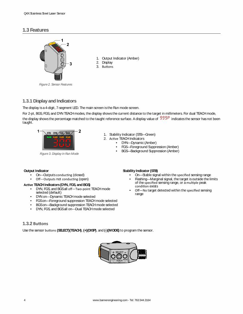
1.3 Features
12
3
Figure 2. Sensor Features
1. Output Indicator (Amber)2. Display3. Buttons
1.3.1 Display and IndicatorsThe display is a 4-digit, 7-segment LED. The main screen is the Run mode screen.For 2-pt, BGS, FGS, and DYN TEACH modes, the display shows the current distance to the target in millimeters. For dual TEACH mode,the display shows the percentage matched to the taught reference surface. A display value of indicates the sensor has not beentaught.
1 2
Figure 3. Display in Run Mode
1. Stability Indicator (STB—Green)2. Active TEACH Indicators
• DYN—Dynamic (Amber)• FGS—Foreground Suppression (Amber)• BGS—Background Suppression (Amber)
Output Indicator• On—Outputs conducting (closed)• Off—Outputs not conducting (open)
Active TEACH Indicators (DYN, FGS, and BGS)• DYN, FGS, and BGS all off—Two-point TEACH mode
selected (default)• DYN on—Dynamic TEACH mode selected• FGS on—Foreground suppression TEACH mode selected• BGS on—Background suppression TEACH mode selected• DYN, FGS, and BGS all on—Dual TEACH mode selected
Stability Indicator (STB)• On—Stable signal within the specified sensing range• Flashing—Marginal signal, the target is outside the limits
of the specified sensing range, or a multiple peakcondition exists
• Off—No target detected within the specified sensingrange
1.3.2 ButtonsUse the sensor buttons (SELECT)(TEACH), (+)(DISP), and (-)(MODE) to program the sensor.
Q4X Stainless Steel Laser Sensor
4 www.bannerengineering.com - Tel: 763.544.3164
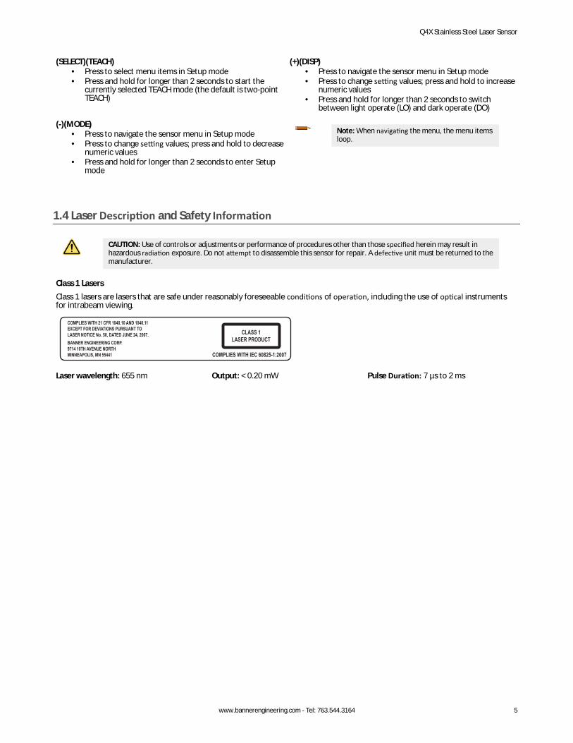
(SELECT)(TEACH)• Press to select menu items in Setup mode• Press and hold for longer than 2 seconds to start the
currently selected TEACH mode (the default is two-pointTEACH)
(+)(DISP)• Press to navigate the sensor menu in Setup mode• Press to change setting values; press and hold to increase
numeric values• Press and hold for longer than 2 seconds to switch
between light operate (LO) and dark operate (DO)
(-)(MODE)• Press to navigate the sensor menu in Setup mode• Press to change setting values; press and hold to decrease
numeric values• Press and hold for longer than 2 seconds to enter Setup
mode
Note: When navigating the menu, the menu itemsloop.
1.4 Laser Description and Safety Information
CAUTION: Use of controls or adjustments or performance of procedures other than those specified herein may result inhazardous radiation exposure. Do not attempt to disassemble this sensor for repair. A defective unit must be returned to themanufacturer.
Class 1 LasersClass 1 lasers are lasers that are safe under reasonably foreseeable conditions of operation, including the use of optical instrumentsfor intrabeam viewing.
Laser wavelength: 655 nm Output: < 0.20 mW Pulse Duration: 7 µs to 2 ms
Q4X Stainless Steel Laser Sensor
www.bannerengineering.com - Tel: 763.544.3164 5
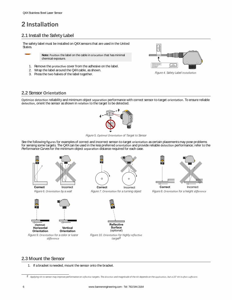
2 Installation2.1 Install the Safety LabelThe safety label must be installed on Q4X sensors that are used in the UnitedStates.
Note: Position the label on the cable in a location that has minimalchemical exposure.
1. Remove the protective cover from the adhesive on the label.2. Wrap the label around the Q4X cable, as shown.3. Press the two halves of the label together.
COMPLIES WITH IEC 60825-1:2007
CLASS 1LASER PRODUCT
COMPLIES WITH 21 CFR 1040.10 AND 1040.11EXCEPT FOR DEVIATIONS PURSUANT TOLASER NOTICE No. 50, DATED JUNE 24, 2007.BANNER ENGINEERING CORP.9714 10TH AVENUE NORTHMINNEAPOLIS, MN 55441
COMP
LIES W
ITH IE
C 60
825-1
:2007
CLAS
S 1LA
SER
PROD
UCT
Figure 4. Safety Label Installation
2.2 Sensor OrientationOptimize detection reliability and minimum object separation performance with correct sensor-to-target orientation. To ensure reliabledetection, orient the sensor as shown in relation to the target to be detected.
Figure 5. Optimal Orientation of Target to Sensor
See the following figures for examples of correct and incorrect sensor-to-target orientation as certain placements may pose problemsfor sensing some targets. The Q4X can be used in the less preferred orientation and provide reliable detection performance; refer to thePerformance Curves for the minimum object separation distance required for each case.
IncorrectCorrectFigure 6. Orientation by a wall
IncorrectCorrectFigure 7. Orientation for a turning object
IncorrectCorrectFigure 8. Orientation for a height difference
Horizontal Orientation
Vertical Orientation
(Optimal)
Figure 9. Orientation for a color or lusterdifference
Reflective Surface (optional)
Figure 10. Orientation for highly reflectivetarget2
2.3 Mount the Sensor1. If a bracket is needed, mount the sensor onto the bracket.
2 Applying tilt to sensor may improve performance on reflective targets. The direction and magnitude of the tilt depends on the application, but a 15° tilt is often sufficient.
Q4X Stainless Steel Laser Sensor
6 www.bannerengineering.com - Tel: 763.544.3164
2. Mount the sensor (or the sensor and the bracket) to the machine or equipment at the desired location. Do not tighten themounting screws at this time.
3. Check the sensor alignment.4. Tighten the mounting screws to secure the sensor (or the sensor and the bracket) in the aligned position.
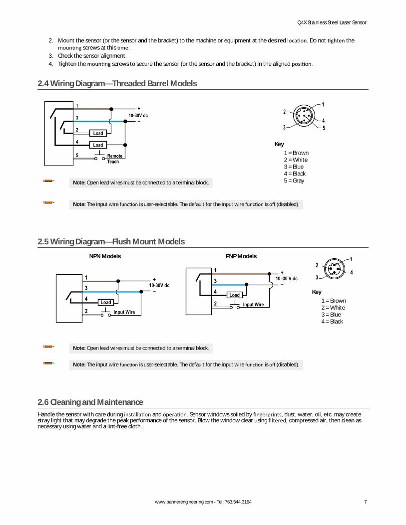
2.4 Wiring Diagram—Threaded Barrel Models
3
1
2
4
5
10-30V dc
RemoteTeach
Load
Load
+
–
Note: Open lead wires must be connected to a terminal block.
1
453
2
Key1 = Brown2 = White3 = Blue4 = Black5 = Gray
Note: The input wire function is user-selectable. The default for the input wire function is off (disabled).
2.5 Wiring Diagram—Flush Mount ModelsNPN Models
Input Wire
10-30V dc
Load
PNP Models
Load
10–30 V dc
Input Wire
1
43
2
Key1 = Brown2 = White3 = Blue4 = Black
Note: Open lead wires must be connected to a terminal block.
Note: The input wire function is user-selectable. The default for the input wire function is off (disabled).
2.6 Cleaning and MaintenanceHandle the sensor with care during installation and operation. Sensor windows soiled by fingerprints, dust, water, oil, etc. may createstray light that may degrade the peak performance of the sensor. Blow the window clear using filtered, compressed air, then clean asnecessary using water and a lint-free cloth.
Q4X Stainless Steel Laser Sensor
www.bannerengineering.com - Tel: 763.544.3164 7
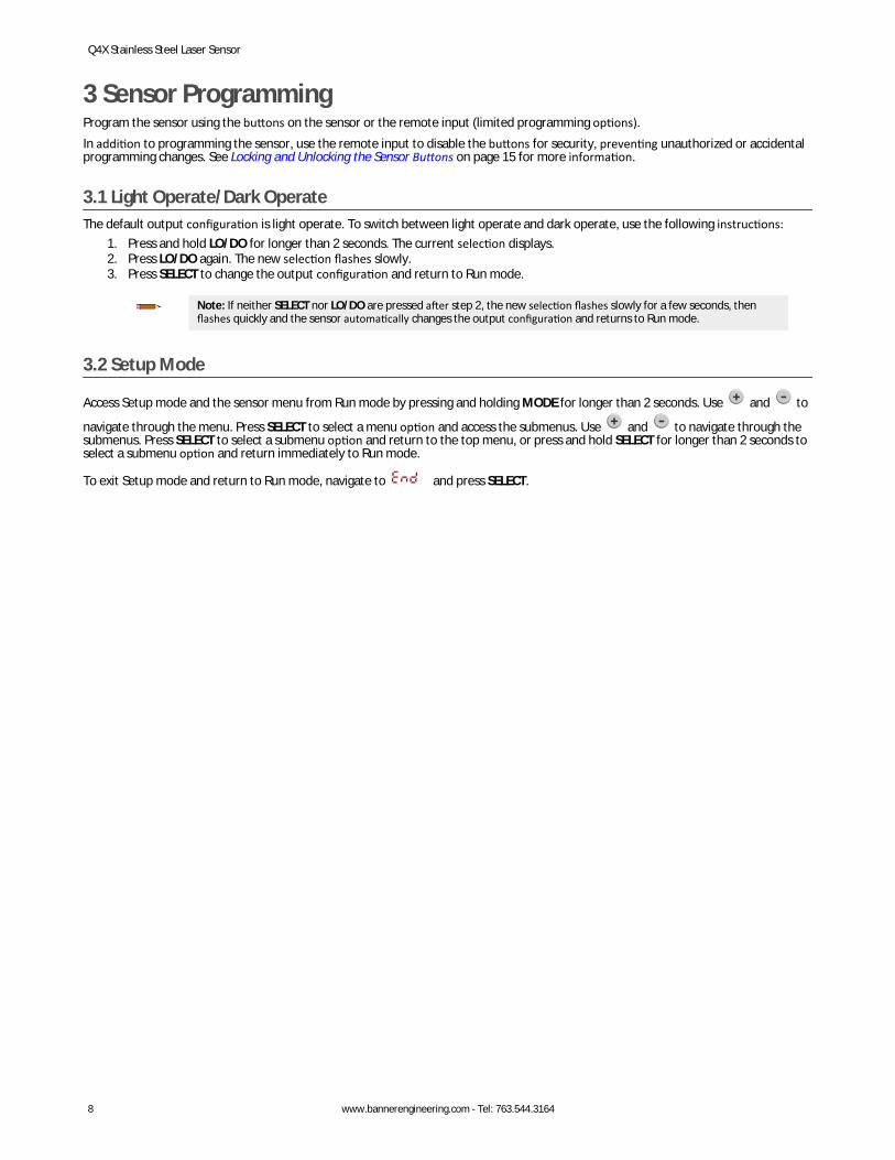
3 Sensor ProgrammingProgram the sensor using the buttons on the sensor or the remote input (limited programming options).In addition to programming the sensor, use the remote input to disable the buttons for security, preventing unauthorized or accidentalprogramming changes. See Locking and Unlocking the Sensor Buttons on page 15 for more information.
3.1 Light Operate/Dark OperateThe default output configuration is light operate. To switch between light operate and dark operate, use the following instructions:
1. Press and hold LO/DO for longer than 2 seconds. The current selection displays.2. Press LO/DO again. The new selection flashes slowly.3. Press SELECT to change the output configuration and return to Run mode.
Note: If neither SELECT nor LO/DO are pressed after step 2, the new selection flashes slowly for a few seconds, thenflashes quickly and the sensor automatically changes the output configuration and returns to Run mode.
3.2 Setup Mode
Access Setup mode and the sensor menu from Run mode by pressing and holding MODE for longer than 2 seconds. Use and to
navigate through the menu. Press SELECT to select a menu option and access the submenus. Use and to navigate through thesubmenus. Press SELECT to select a submenu option and return to the top menu, or press and hold SELECT for longer than 2 seconds toselect a submenu option and return immediately to Run mode.
To exit Setup mode and return to Run mode, navigate to and press SELECT.
Q4X Stainless Steel Laser Sensor
8 www.bannerengineering.com - Tel: 763.544.3164
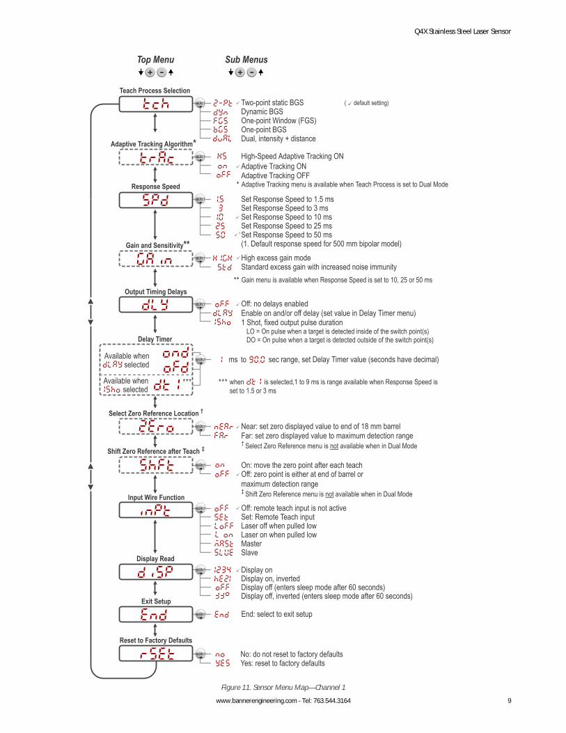
Two-point static BGSDynamic BGS
One-point BGSDual, intensity + distance
One-point Window (FGS)
Top Menu
Set Response Speed to 1.5 msSet Response Speed to 3 msSet Response Speed to 10 ms
Set Response Speed to 50 ms (1. Default response speed for 500 mm bipolar model)
Set Response Speed to 25 ms
Off: no delays enabledEnable on and/or off delay (set value in Delay Timer menu)1 Shot, fixed output pulse duration
LO = On pulse when a target is detected inside of the switch point(s)DO = On pulse when a target is detected outside of the switch point(s)
Near: set zero displayed value to end of 18 mm barrelFar: set zero displayed value to maximum detection range
sec range, set Delay Timer value (seconds have decimal)
Gain menu is available when Response Speed is set to 10, 25 or 50 ms
† Select Zero Reference menu is not available when in Dual Mode
‡ Shift Zero Reference menu is not available when in Dual Mode
Adaptive Tracking menu is available when Teach Process is set to Dual Mode
Laser off when pulled lowLaser on when pulled low
Set: Remote Teach inputOff: remote teach input is not active
MasterSlave
Display onDisplay on, invertedDisplay off (enters sleep mode after 60 seconds)Display off, inverted (enters sleep mode after 60 seconds)
End: select to exit setup
No: do not reset to factory defaultsYes: reset to factory defaults
On: move the zero point after each teachOff: zero point is either at end of barrel or maximum detection range
to
Teach Process Selection
Response Speed
Output Timing Delays
Select Zero Reference Location †
Delay Timer
Shift Zero Reference after Teach ‡
Input Wire Function
Display Read
Exit Setup
Reset to Factory Defaults
Available when selected
Available when selected
Sub Menus
ms
( default setting)
High excess gain modeStandard excess gain with increased noise immunity
Gain and Sensitivity**
when is selected,1 to 9 ms is range available when Response Speed is set to 1.5 or 3 ms
Adaptive Tracking ONAdaptive Tracking OFF
High-Speed Adaptive Tracking ONAdaptive Tracking Algorithm*
Figure 11. Sensor Menu Map—Channel 1
Q4X Stainless Steel Laser Sensor
www.bannerengineering.com - Tel: 763.544.3164 9
3.2.1 TEACH Mode Use this menu to select the TEACH mode. The default is two-point TEACH.
• —Two-point static background suppression• —Dynamic background suppression• —One-point window (foreground suppression)• —One-point background suppression
• —Dual (intensity + distance) windowAfter the TEACH mode is selected, from Run mode, press and hold TEACH for longer than 2 seconds to start the TEACH mode andprogram the sensor. See TEACH Procedures on page 16 for additional information and remote input TEACH instructions.
3.2.2 Adaptive Tracking Use these menus to set the adaptive tracking algorithm. This menu is available only if dual (intensity + distance) mode is selected.
• —High-Speed Adaptive Tracking On
• —Adaptive Tracking On (default)
• —Adaptive Tracking Off
3.2.3 Response Speed Use this menu to select the response speed. The default is 10 milliseconds. For 500 mm threaded barrel models, the default is 50milliseconds.
• —1.5 milliseconds
• —3 milliseconds
• —10 milliseconds
• —25 milliseconds
• —50 millisecondsTable 1: Tradeoffs
Response Speed Response Speed in SyncMode
Repeatability Ambient LightRejection
Excess Gain
1.5 ms 3 ms 500 µs Disabled
See Table 9 on page 24
3 ms 6 ms 500 µs Enabled
10 ms 20 ms 2 ms Enabled
25 ms 50 ms 5 ms Enabled
50 ms 100 ms 10 ms Enabled
3.2.4 Gain and Sensitivity Use this menu to set the excess gain mode. This menu is only available when a 10, 25, or 50 millisecond response speed is selected. It isnot available for 1.5 or 3 millisecond response speeds.
• —High excess gain mode• —Standard excess gain mode with increased noise immunity
3.2.5 Output Timing Delays Use this menu to select the output timing delay to be set. On and off delay timers can be used together. The default is no delay.
• —No delay
• —Delay—enables the selection of on and off delay timers
• —One-shot—enables a one-shot, fixed output pulse duration
Q4X Stainless Steel Laser Sensor
10 www.bannerengineering.com - Tel: 763.544.3164

Output
OFF Delay
ON Delay
Time
1-Shot
ON
OFF
D
D
D
D
D D
(D = 1ms - 90.0s)Figure 12. Output Timing Delays
When one of the timing delay options is chosen, the sensor returns to the Setup menu and additional options become available to setthe parameter(s):
• —On delay
• —Off delay
• —One-shot delay timer
Note: For the one-shot delay timer:• LO = On pulse when a target is detected inside of the switch point(s)• DO = On pulse when a target is detected outside of the switch point(s)
3.2.6 Delay Timers Use these menus to set the delay timers. These menus are available only if an output timing delay is selected.
For and , the default is 0.
For , the default is 10 milliseconds for 10, 25, and 50 millisecond response speeds and 1 millisecond for 1.5 and 3 millisecondsresponse speeds.
Use and to scroll through the values. Values greater than 10 increase or decrease by increments of 10. Millisecond values do notinclude the decimal point; seconds values include the decimal point.
• 1 to 9 ms (when is selected, the 1 to 9 ms range is available for 1.5 and 3 ms response times)• 10 to 90 ms• 100 to 900 ms• 1.0 to 90.0 s
3.2.7 Zero Reference Location
Use this menu to select the zero reference location. The default is , 0 = the front of the sensor. This menu is not available in dual(intensity + distance) mode.
• —0 = the front of the sensor; the measurement increases further from the sensor• —0 = maximum range; the measurement increases closer to the sensor
3.2.8 Shift the Zero Reference Location after a TEACH
Use this menu to select whether the sensor shifts the zero reference location based on the last TEACH process. The default is , 0= the front of the sensor or the maximum range. This menu is not available in dual (intensity + distance) mode.
• —Shift the zero reference location to one of the taught positions with each TEACH
Q4X Stainless Steel Laser Sensor
www.bannerengineering.com - Tel: 763.544.3164 11
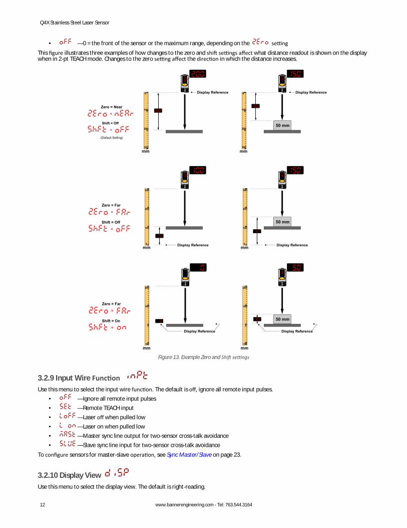
• —0 = the front of the sensor or the maximum range, depending on the settingThis figure illustrates three examples of how changes to the zero and shift settings affect what distance readout is shown on the displaywhen in 2-pt TEACH mode. Changes to the zero setting affect the direction in which the distance increases.
Zero = Near
(Default Setting)
Shift = Off
=
=
Zero = Far
Shift = Off
=
=
Zero = Far
Shift = On
=
=
Display Reference Display Reference
50 mm
50 mm
50 mm
Display Reference Display Reference
Display Reference
100
0
200
300
mm
0
-100
100
200
mm
0
-100
100
200
mm
100
0
200
300
mm
200
0
100
300mm
200
0
100
300mm
Display Reference
Figure 13. Example Zero and Shift settings
3.2.9 Input Wire Function Use this menu to select the input wire function. The default is off, ignore all remote input pulses.
• —Ignore all remote input pulses• —Remote TEACH input• —Laser off when pulled low• —Laser on when pulled low• —Master sync line output for two-sensor cross-talk avoidance• —Slave sync line input for two-sensor cross-talk avoidance
To configure sensors for master-slave operation, see Sync Master/Slave on page 23.
3.2.10 Display View Use this menu to select the display view. The default is right-reading.
Q4X Stainless Steel Laser Sensor
12 www.bannerengineering.com - Tel: 763.544.3164
• —Right-reading• —Inverted• —Right-reading and the display enters sleep mode after 60 seconds• —Inverted and the display enters sleep mode after 60 seconds
When the sensor is in sleep mode, the display wakes with the first button press.
3.2.11 Exit Setup Mode
Navigate to and press SELECT to exit Setup mode and return to Run mode.
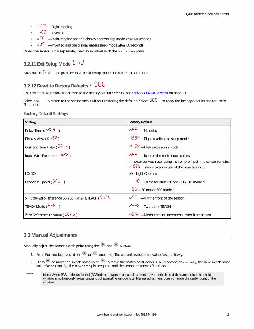
3.2.12 Reset to Factory Defaults Use this menu to restore the sensor to the factory default settings. See Factory Default Settings on page 13.
Select to return to the sensor menu without restoring the defaults. Select to apply the factory defaults and return toRun mode.
Factory Default Settings
Setting Factory Default
Delay Timers ( ) —No delay
Display View ( ) —Right-reading, no sleep mode
Gain and Sensitivity ( ) —High excess gain mode
Input Wire Function ( ) —Ignore all remote input pulsesIf the sensor was reset using the remote input, the sensor remainsin mode to allow use of the remote input.
LO/DO LO—Light Operate
Response Speed ( ) —10 ms for 100/110 and 300/310 models
—50 ms for 500 models
Shift the Zero Reference Location after a TEACH ( ) —0 = the front of the sensor
TEACH Mode ( ) —Two-point TEACH
Zero Reference Location ( ) —Measurement increases further from sensor
3.3 Manual Adjustments
Manually adjust the sensor switch point using the and buttons.
1. From Run mode, press either or one time. The current switch point value flashes slowly.
2. Press to move the switch point up or to move the switch point down. After 1 second of inactivity, the new switch pointvalue flashes rapidly, the new setting is accepted, and the sensor returns to Run mode.
Note: When FGS mode is selected (FGS indicator is on), manual adjustment moves both sides of the symmetrical thresholdwindow simultaneously, expanding and collapsing the window size. Manual adjustment does not move the center point of thewindow.
Q4X Stainless Steel Laser Sensor
www.bannerengineering.com - Tel: 763.544.3164 13
Note: When dual mode is selected (DYN, FGS, and BGS indicators are on), after the TEACH process is completed, use the manualadjustment to adjust the sensitivity of the thresholds around the taught reference point. The taught reference point is acombination of the measured distance and returned signal intensity from the reference target. Manual adjustment does not
move the taught reference point, but pressing increases the sensitivity, and pressing decreases the sensitivity. When re-positioning the sensor or changing the reference target, re-teach the sensor.
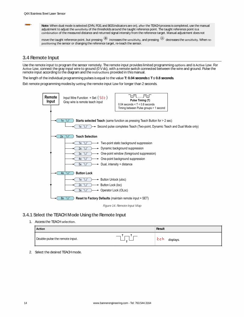
3.4 Remote InputUse the remote input to program the sensor remotely. The remote input provides limited programming options and is Active Low. ForActive Low, connect the gray input wire to ground (0 V dc), with a remote switch connected between the wire and ground. Pulse theremote input according to the diagram and the instructions provided in this manual.The length of the individual programming pulses is equal to the value T: 0.04 seconds ≤ T ≤ 0.8 seconds.Exit remote programming modes by setting the remote input Low for longer than 2 seconds.
1x
2x Teach Selection
Starts selected Teach (same function as pressing Teach Button for > 2 sec)1x Second pulse completes Teach (Two-point, Dynamic Teach and Dual Mode only)
0.04 seconds < T < 0.8 secondsTiming between Pulse groups > 1 second
Pulse Timing (T)Input Wire Function = Set Gray wire is remote teach input
2x1x Two-point static background suppression
Dynamic background suppression
4x3x One-point window (foreground suppression)
One-point background suppression5x Dual, intensity + distance
4x
2x1x Button Unlock (uloc)
3x Operator Lock (OLoc)Button Lock (loc)
Button Lock
8x Reset to Factory Defaults (maintain remote input = SET)
Remote Input
Figure 14. Remote Input Map
3.4.1 Select the TEACH Mode Using the Remote Input1. Access the TEACH selection.
Action Result
Double-pulse the remote input.T T
T displays.
2. Select the desired TEACH mode.
Q4X Stainless Steel Laser Sensor
14 www.bannerengineering.com - Tel: 763.544.3164
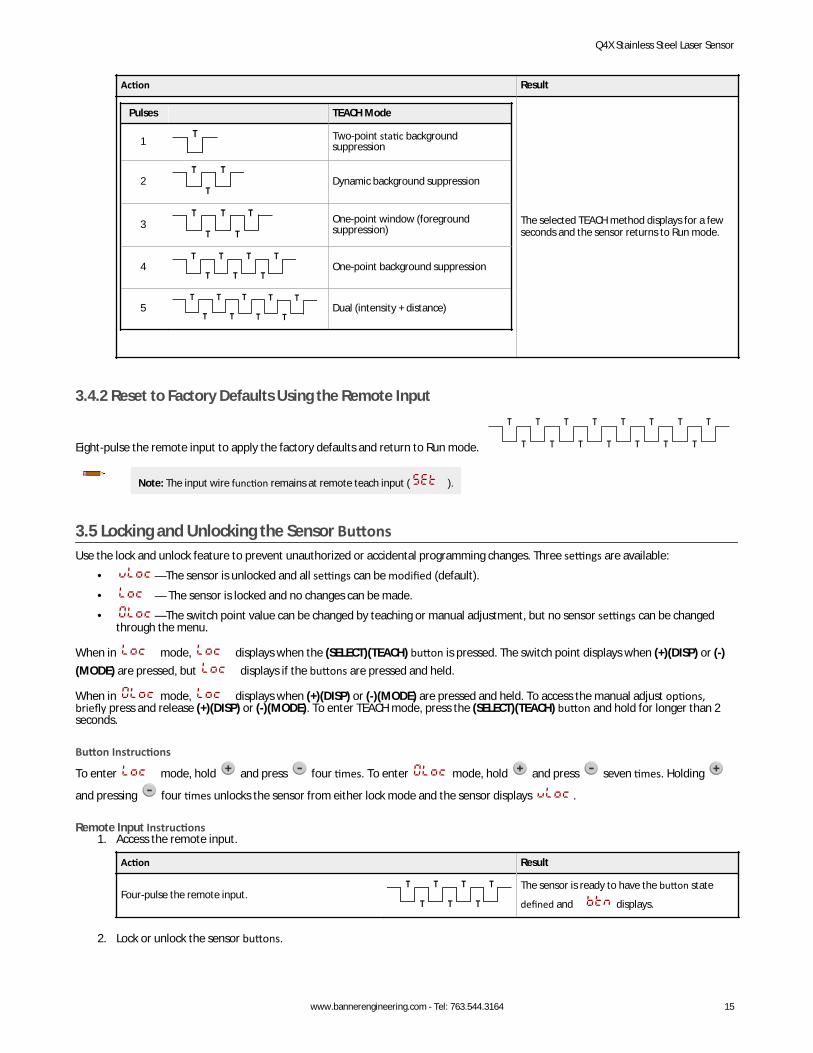
Action Result
Pulses TEACH Mode
1T Two-point static background
suppression
2T T
TDynamic background suppression
3T T
T
T
TOne-point window (foregroundsuppression)
4T T
T T T
T TOne-point background suppression
5T T
T
T
T
T
T
T
TDual (intensity + distance)
The selected TEACH method displays for a fewseconds and the sensor returns to Run mode.
3.4.2 Reset to Factory Defaults Using the Remote Input
Eight-pulse the remote input to apply the factory defaults and return to Run mode. T
T
T
T
T
T
T
T
T
T
T
T T
T
T
Note: The input wire function remains at remote teach input ( ).
3.5 Locking and Unlocking the Sensor ButtonsUse the lock and unlock feature to prevent unauthorized or accidental programming changes. Three settings are available:
• —The sensor is unlocked and all settings can be modified (default).
• — The sensor is locked and no changes can be made.
• —The switch point value can be changed by teaching or manual adjustment, but no sensor settings can be changedthrough the menu.
When in mode, displays when the (SELECT)(TEACH) button is pressed. The switch point displays when (+)(DISP) or (-)(MODE) are pressed, but displays if the buttons are pressed and held.
When in mode, displays when (+)(DISP) or (-)(MODE) are pressed and held. To access the manual adjust options,briefly press and release (+)(DISP) or (-)(MODE). To enter TEACH mode, press the (SELECT)(TEACH) button and hold for longer than 2seconds.
Button Instructions
To enter mode, hold and press four times. To enter mode, hold and press seven times. Holding
and pressing four times unlocks the sensor from either lock mode and the sensor displays .
Remote Input Instructions1. Access the remote input.
Action Result
Four-pulse the remote input.T T
T T T
T T The sensor is ready to have the button state
defined and displays.
2. Lock or unlock the sensor buttons.
Q4X Stainless Steel Laser Sensor
www.bannerengineering.com - Tel: 763.544.3164 15
Action Result
Single-pulse the remote input to unlock the sensor.T displays and the sensor returns to Run
mode.
Double-pulse the remote input to lock the sensor.T T
T displays and the sensor returns to Run
mode.
Triple-pulse the remote input to apply the operator lock tothe sensor
T T
T
T
T displays and the sensor returns to Run
mode
3.6 TEACH ProceduresUse the following procedures to teach the sensor.
To cancel a TEACH procedure, press TEACH for longer than 2 seconds, or hold the remote input Low for longer than 2 seconds. momentarily displays when a TEACH procedure is canceled.
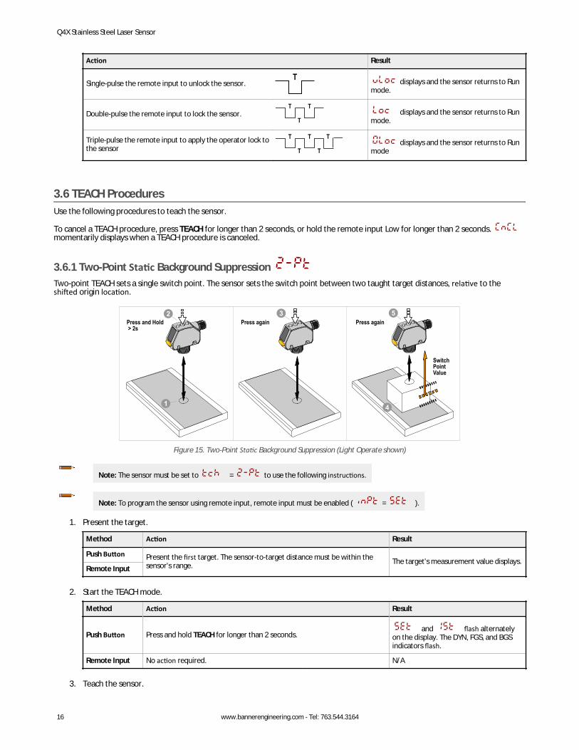
3.6.1 Two-Point Static Background Suppression Two-point TEACH sets a single switch point. The sensor sets the switch point between two taught target distances, relative to theshifted origin location.
2Press and Hold > 2s
Press again Press again3
1
Switch Point Value
5
4
Figure 15. Two-Point Static Background Suppression (Light Operate shown)
Note: The sensor must be set to = to use the following instructions.
Note: To program the sensor using remote input, remote input must be enabled ( = ).
1. Present the target.
Method Action Result
Push Button Present the first target. The sensor-to-target distance must be within thesensor's range. The target's measurement value displays.
Remote Input
2. Start the TEACH mode.
Method Action Result
Push Button Press and hold TEACH for longer than 2 seconds. and flash alternately
on the display. The DYN, FGS, and BGSindicators flash.
Remote Input No action required. N/A
3. Teach the sensor.
Q4X Stainless Steel Laser Sensor
16 www.bannerengineering.com - Tel: 763.544.3164
Method Action Result
Push Button Press TEACH to teach the target. The sensor is taught the first target.
, , and the currentdistance measurement flash alternatelyon the display. The DYN, FGS, and BGSindicators flash.
Remote Input Single-pulse the remote input.T
4. Present the target.
Method Action Result
Push ButtonPresent the second target. The sensor-to-target distance must be within thesensor's range.
, , and the distancemeasurement flash alternately on thedisplay. The DYN, FGS, and BGS indicatorsflash.
Remote Input
5. Teach the sensor.
Method Action Result
Push Button Press TEACH to teach the target.The new switch point flashes rapidly andthe sensor returns to Run mode.Remote Input Single-pulse the remote input.
T
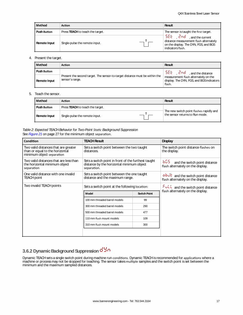
Table 2: Expected TEACH Behavior for Two-Point Static Background SuppressionSee Figure 21 on page 27 for the minimum object separation.
Condition TEACH Result Display
Two valid distances that are greaterthan or equal to the horizontalminimum object separation
Sets a switch point between the two taughtdistances.
The switch point distance flashes onthe display.
Two valid distances that are less thanthe horizontal minimum objectseparation
Sets a switch point in front of the furthest taughtdistance by the horizontal minimum objectseparation.
and the switch point distanceflash alternately on the display.
One valid distance with one invalidTEACH point
Sets a switch point between the one taughtdistance and the maximum range. and the switch point distance
flash alternately on the display.
Two invalid TEACH points Sets a switch point at the following location:
Model Switch Point
100 mm threaded barrel models 99
300 mm threaded barrel models 290
500 mm threaded barrel models 477
110 mm flush mount models 109
310 mm flush mount models 300
and the switch point distanceflash alternately on the display.
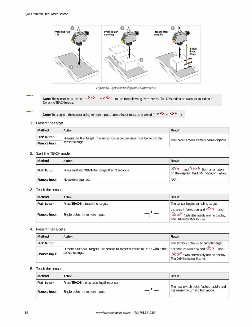
3.6.2 Dynamic Background SuppressionDynamic TEACH sets a single switch point during machine run conditions. Dynamic TEACH is recommended for applications where amachine or process may not be stopped for teaching. The sensor takes multiple samples and the switch point is set between theminimum and the maximum sampled distances.
Q4X Stainless Steel Laser Sensor
www.bannerengineering.com - Tel: 763.544.3164 17
2Press and Hold > 2s
3
Switch Point Value
1
5
4
Press to start sampling
Press to stop sampling
Figure 16. Dynamic Background Suppression
Note: The sensor must be set to = to use the following instructions. The DYN indicator is amber to indicateDynamic TEACH mode.
Note: To program the sensor using remote input, remote input must be enabled ( = ).
1. Present the target.
Method Action Result
Push Button Present the first target. The sensor-to-target distance must be within thesensor's range. The target's measurement value displays.
Remote Input
2. Start the TEACH mode.
Method Action Result
Push Button Press and hold TEACH for longer than 2 seconds. and flash alternatelyon the display. The DYN indicator flashes.
Remote Input No action required. N/A
3. Teach the sensor.
Method Action Result
Push Button Press TEACH to teach the target. The sensor begins sampling target
distance information and and
flash alternately on the display.The DYN indicator flashes.
Remote Input Single-pulse the remote input.T
4. Present the targets.
Method Action Result
Push Button
Present additional targets. The sensor-to-target distance must be within thesensor's range.
The sensor continues to sample target
distance information and and
flash alternately on the display.The DYN indicator flashes.
Remote Input
5. Teach the sensor.
Method Action Result
Push Button Press TEACH to stop teaching the sensor.The new switch point flashes rapidly andthe sensor returns to Run mode.Remote Input Single-pulse the remote input.
T
Q4X Stainless Steel Laser Sensor
18 www.bannerengineering.com - Tel: 763.544.3164
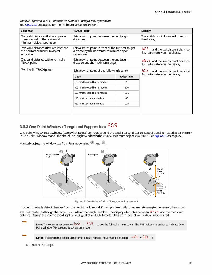
Table 3: Expected TEACH Behavior for Dynamic Background SuppressionSee Figure 21 on page 27 for the minimum object separation.
Condition TEACH Result Display
Two valid distances that are greaterthan or equal to the horizontalminimum object separation
Sets a switch point between the two taughtdistances.
The switch point distance flashes onthe display.
Two valid distances that are less thanthe horizontal minimum objectseparation
Sets a switch point in front of the furthest taughtdistance by the horizontal minimum objectseparation.
and the switch point distanceflash alternately on the display.
One valid distance with one invalidTEACH point
Sets a switch point between the one taughtdistance and the maximum range. and the switch point distance
flash alternately on the display.
Two invalid TEACH points Sets a switch point at the following location:
Model Switch Point
100 mm threaded barrel models 75
300 mm threaded barrel models 200
500 mm threaded barrel models 375
110 mm flush mount models 85
310 mm flush mount models 210
and the switch point distanceflash alternately on the display.
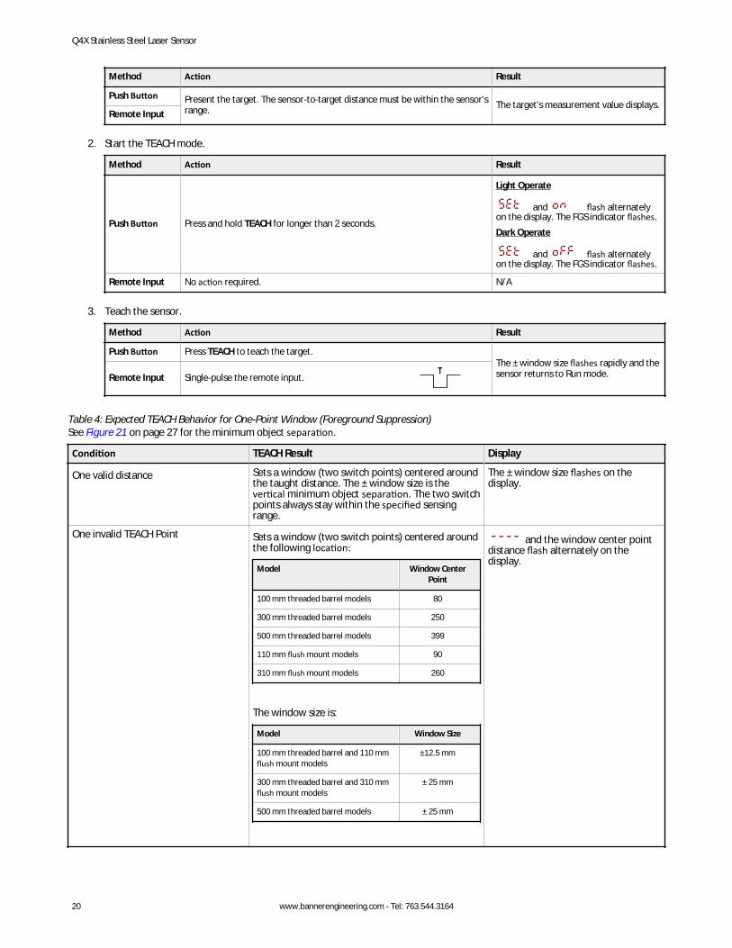
3.6.3 One-Point Window (Foreground Suppression) One-point window sets a window (two switch points) centered around the taught target distance. Loss of signal is treated as a detectionin One-Point Window mode. The size of the taught window is the vertical minimum object separation. See Figure 21 on page 27.
Manually adjust the window size from Run mode using and .
Switch Point Value A
Switch Point Value -A
2Press and Hold > 2s
1
3Press again
Figure 17. One-Point Window (Foreground Suppression)
In order to reliably detect changes from the taught background, if multiple laser reflections are returning to the sensor, the outputstatus is treated as though the target is outside of the taught window. The display alternates between and the measureddistance. Realign the laser to avoid light reflecting off of multiple targets if this extra level of verification is not desired.
Note: The sensor must be set to = to use the following instructions. The FGS indicator is amber to indicate One-Point Window (Foreground Suppression) mode.
Note: To program the sensor using remote input, remote input must be enabled ( = ).
1. Present the target.
Q4X Stainless Steel Laser Sensor
www.bannerengineering.com - Tel: 763.544.3164 19
Method Action Result
Push Button Present the target. The sensor-to-target distance must be within the sensor'srange. The target's measurement value displays.
Remote Input
2. Start the TEACH mode.
Method Action Result
Push Button Press and hold TEACH for longer than 2 seconds.
Light Operate
and flash alternatelyon the display. The FGS indicator flashes.Dark Operate
and flash alternatelyon the display. The FGS indicator flashes.
Remote Input No action required. N/A
3. Teach the sensor.
Method Action Result
Push Button Press TEACH to teach the target.The ± window size flashes rapidly and thesensor returns to Run mode.Remote Input Single-pulse the remote input.
T
Table 4: Expected TEACH Behavior for One-Point Window (Foreground Suppression)See Figure 21 on page 27 for the minimum object separation.
Condition TEACH Result Display
One valid distance Sets a window (two switch points) centered aroundthe taught distance. The ± window size is thevertical minimum object separation. The two switchpoints always stay within the specified sensingrange.
The ± window size flashes on thedisplay.
One invalid TEACH Point Sets a window (two switch points) centered aroundthe following location:
Model Window CenterPoint
100 mm threaded barrel models 80
300 mm threaded barrel models 250
500 mm threaded barrel models 399
110 mm flush mount models 90
310 mm flush mount models 260
The window size is:
Model Window Size
100 mm threaded barrel and 110 mmflush mount models
±12.5 mm
300 mm threaded barrel and 310 mmflush mount models
± 25 mm
500 mm threaded barrel models ± 25 mm
and the window center pointdistance flash alternately on thedisplay.
Q4X Stainless Steel Laser Sensor
20 www.bannerengineering.com - Tel: 763.544.3164
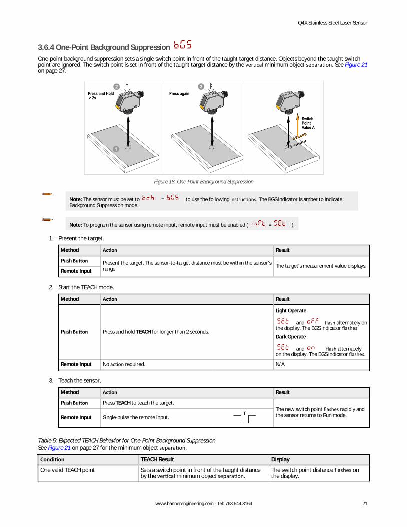
3.6.4 One-Point Background Suppression One-point background suppression sets a single switch point in front of the taught target distance. Objects beyond the taught switchpoint are ignored. The switch point is set in front of the taught target distance by the vertical minimum object separation. See Figure 21on page 27.
Press and Hold > 2s
Press again
Switch Point Value A
2
1
3
Figure 18. One-Point Background Suppression
Note: The sensor must be set to = to use the following instructions. The BGS indicator is amber to indicateBackground Suppression mode.
Note: To program the sensor using remote input, remote input must be enabled ( = ).
1. Present the target.
Method Action Result
Push Button Present the target. The sensor-to-target distance must be within the sensor'srange. The target's measurement value displays.
Remote Input
2. Start the TEACH mode.
Method Action Result
Push Button Press and hold TEACH for longer than 2 seconds.
Light Operate
and flash alternately onthe display. The BGS indicator flashes.Dark Operate
and flash alternatelyon the display. The BGS indicator flashes.
Remote Input No action required. N/A
3. Teach the sensor.
Method Action Result
Push Button Press TEACH to teach the target.The new switch point flashes rapidly andthe sensor returns to Run mode.Remote Input Single-pulse the remote input.
T
Table 5: Expected TEACH Behavior for One-Point Background SuppressionSee Figure 21 on page 27 for the minimum object separation.
Condition TEACH Result Display
One valid TEACH point Sets a switch point in front of the taught distanceby the vertical minimum object separation.
The switch point distance flashes onthe display.
Q4X Stainless Steel Laser Sensor
www.bannerengineering.com - Tel: 763.544.3164 21
Condition TEACH Result Display
One invalid TEACH point Sets a switch point at the following location:
Model Switch Point
100 mm threaded barrel models 75
300 mm threaded barrel models 200
500 mm threaded barrel models 375
110 mm flush mount models 85
310 mm flush mount models 210
and the switch point distanceflash alternately on the display.
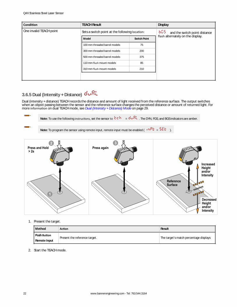
3.6.5 Dual (Intensity + Distance) Dual (intensity + distance) TEACH records the distance and amount of light received from the reference surface. The output switcheswhen an object passing between the sensor and the reference surface changes the perceived distance or amount of returned light. Formore information on dual TEACH mode, see Dual (Intensity + Distance) Mode on page 29.
Note: To use the following instructions, set the sensor to = . The DYN, FGS, and BGS indicators are amber.
Note: To program the sensor using remote input, remote input must be enabled ( = ).
2Press and Hold > 2s
1
3Press again
IncreasedHeightand/orIntensity
DecreasedHeightand/orIntensity
ReferenceSurface
1. Present the target.
Method Action Result
Push Button
Remote InputPresent the reference target. The target's match percentage displays
2. Start the TEACH mode.
Q4X Stainless Steel Laser Sensor
22 www.bannerengineering.com - Tel: 763.544.3164
Method Action Result
Push Button Press and hold the TEACH button for more than 2 seconds.
Light Operate: and flash on the display. The DYN, FGS, andBGS indicators flash.
Dark Operate: and flash on the display. The DYN, FGS, andBGS indicators flash.
Remote Input No action required. N/A
3. Teach the sensor.
Method Action Result
Push Button Press the TEACH button.The switching threshold flashes rapidlyand the sensor returns to Run mode.Remote Input Single-pulse the remote input.
T
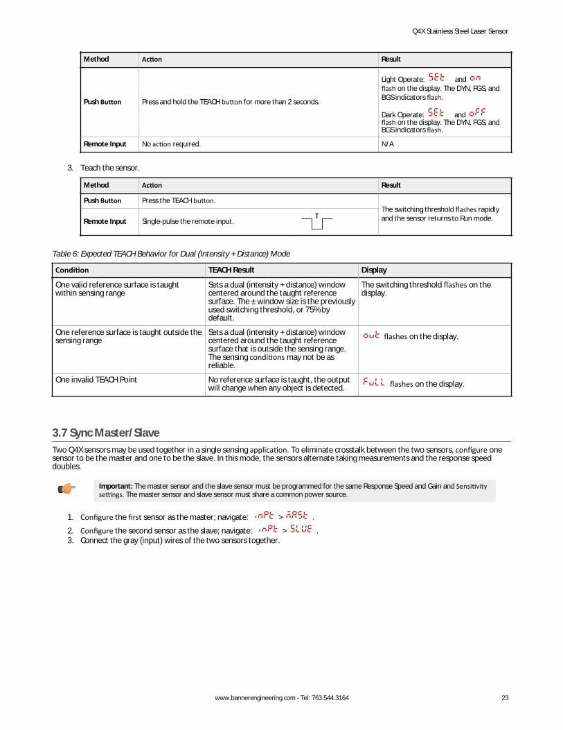
Table 6: Expected TEACH Behavior for Dual (Intensity + Distance) Mode
Condition TEACH Result Display
One valid reference surface is taughtwithin sensing range
Sets a dual (intensity + distance) windowcentered around the taught referencesurface. The ± window size is the previouslyused switching threshold, or 75% bydefault.
The switching threshold flashes on thedisplay.
One reference surface is taught outside thesensing range
Sets a dual (intensity + distance) windowcentered around the taught referencesurface that is outside the sensing range.The sensing conditions may not be asreliable.
flashes on the display.
One invalid TEACH Point No reference surface is taught, the outputwill change when any object is detected. flashes on the display.
3.7 Sync Master/SlaveTwo Q4X sensors may be used together in a single sensing application. To eliminate crosstalk between the two sensors, configure onesensor to be the master and one to be the slave. In this mode, the sensors alternate taking measurements and the response speeddoubles.
Important: The master sensor and the slave sensor must be programmed for the same Response Speed and Gain and Sensitivitysettings. The master sensor and slave sensor must share a common power source.
1. Configure the first sensor as the master; navigate: > .2. Configure the second sensor as the slave; navigate: > .3. Connect the gray (input) wires of the two sensors together.
Q4X Stainless Steel Laser Sensor
www.bannerengineering.com - Tel: 763.544.3164 23
4 SpecificationsSensing Beam
Visible red Class 1 laser, 655 nmSupply Voltage (Vcc)
10 to 30 V dcPower and Current Consumption, exclusive of load
< 675 mWSensing Range—Threaded Barrel Models
500 mm models: 25 mm to 500 mm (0.98 in to 19.69 in)300 mm models: 25 mm to 300 mm (0.98 in to 11.81 in)100 mm models: 25 mm to 100 mm (0.98 in to 3.94 in)
Sensing Range—Flush Mount Models310 mm models: 35 mm to 310 mm (1.38 in to 12.20 in)110 mm models: 35 mm to 110 mm (1.38 in to 4.33 in)
Output ConfigurationThreaded Barrel Models: Bipolar (1 PNP and 1 NPN) outputFlush Mount Models: PNP or NPN output, depending on model
Output Rating100 mA total maximum (protected against continuous overload and shortcircuit)Off-state leakage current: < 5 µA at 30 V dcPNP On-state saturation voltage: < 1.5 V dc at 100 mA loadNPN On-state saturation voltage: < 1.0 V dc at 100 mA load
Discrete Output Distance RepeatabilityTable 7: Beam Spot Size—300/310 mm and 500 mm Models
Distance (mm) Repeatability
Threaded Barrel Models Flush Mount Models
25 to 50 mm 35 to 60 mm ± 0.5 mm
50 to maximum range 60 to 310 mm ± 1% of range
Table 8: Beam Spot Size—100/110 mm Models
Distance (mm) Repeatability
Threaded Barrel Models Flush Mount Models
25 to 100 mm 35 to 110 mm +/-0.2 mm
Remote InputAllowable Input Voltage Range: 0 to VccActive Low (internal weak pullup—sinking current): Low State < 2.0 V at 1 mAmax.
Supply Protection CircuitryProtected against reverse polarity and transient overvoltages
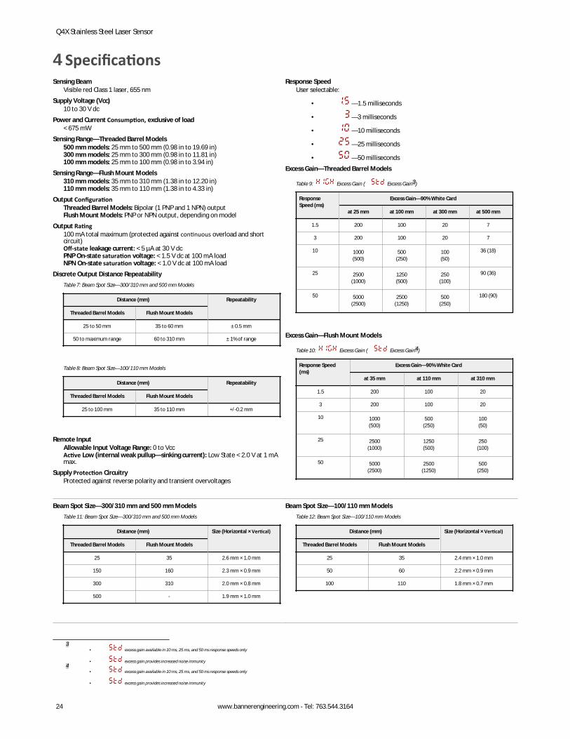
Response SpeedUser selectable:
• —1.5 milliseconds
• —3 milliseconds
• —10 milliseconds
• —25 milliseconds
• —50 millisecondsExcess Gain—Threaded Barrel Models
Table 9: Excess Gain ( Excess Gain3)
ResponseSpeed (ms)
Excess Gain—90% White Card
at 25 mm at 100 mm at 300 mm at 500 mm
1.5 200 100 20 7
3 200 100 20 7
10 1000(500)
500(250)
100(50)
36 (18)
25 2500(1000)
1250(500)
250(100)
90 (36)
50 5000(2500)
2500(1250)
500(250)
180 (90)
Excess Gain—Flush Mount Models
Table 10: Excess Gain ( Excess Gain4)
Response Speed(ms)
Excess Gain—90% White Card
at 35 mm at 110 mm at 310 mm
1.5 200 100 20
3 200 100 20
10 1000(500)
500(250)
100(50)
25 2500(1000)
1250(500)
250(100)
50 5000(2500)
2500(1250)
500(250)
Beam Spot Size—300/310 mm and 500 mm ModelsTable 11: Beam Spot Size—300/310 mm and 500 mm Models
Distance (mm) Size (Horizontal × Vertical)
Threaded Barrel Models Flush Mount Models
25 35 2.6 mm × 1.0 mm
150 160 2.3 mm × 0.9 mm
300 310 2.0 mm × 0.8 mm
500 - 1.9 mm × 1.0 mm
Beam Spot Size—100/110 mm ModelsTable 12: Beam Spot Size—100/110 mm Models
Distance (mm) Size (Horizontal × Vertical)
Threaded Barrel Models Flush Mount Models
25 35 2.4 mm × 1.0 mm
50 60 2.2 mm × 0.9 mm
100 110 1.8 mm × 0.7 mm
3• excess gain available in 10 ms, 25 ms, and 50 ms response speeds only
• excess gain provides increased noise immunity4
• excess gain available in 10 ms, 25 ms, and 50 ms response speeds only
• excess gain provides increased noise immunity
Q4X Stainless Steel Laser Sensor
24 www.bannerengineering.com - Tel: 763.544.3164

Delay at Power Up< 750 ms
Maximum TorqueSide mounting: 1 N·m (9 in·lbs)Nose mounting: 20 N·m (177 in·lbs)
Ambient Light Immunity> 5,000 lux at 300 mm> 2,000 lux at 500 mm
ConnectorThreaded Barrel Models: Integral 5-pin M12/Euro-style male quick disconnect(QD)Flush Mount Models: Integral 4-pin M12/Euro-style male quick disconnect(QD)
ConstructionHousing: 316 L stainless steelLens cover: PMMA acrylicLightpipe and display window: polysulfone
Temperature Effect0.05 mm/°C at <125 mm (threaded barrel models)/< 135 mm (flush mountmodels)0.35 mm/°C at 300 mm (threaded barrel models)/< 310 mm (flush mountmodels)1 mm/°C at 500 mm (threaded barrel models)
Chemical CompatibilityCompatible with commonly used acidic or caustic cleaning and disinfectingchemicals used in equipment cleaning and sanitation. ECOLAB® certified.Compatible with typical cutting fluids and lubricating fluids used in machiningcenters
Application NoteFor optimum performance, allow 10 minutes for the sensor to warm up
Environmental RatingIEC IP67 per IEC60529IEC IP68 per IEC60529IEC IP69K per DIN40050-9
VibrationMIL-STD-202G, Method 201A (10 Hz to 60 Hz, 0.06 inch (1.52 mm) doubleamplitude, 2 hours each along X, Y and Z axes), with sensor operating
ShockMIL-STD-202G, Method 213B, Condition I (100G 6x along X, Y and Z axes, 18total shocks), with sensor operating
Operating Conditions−10 °C to +50 °C (+14 °F to +122 °F)35% to 95% relative humidity
Storage Temperature–25 °C to +75 °C (−13 °F to +167 °F)
Required Overcurrent Protection
WARNING: Electrical connections must be made byqualified personnel in accordance with local andnational electrical codes and regulations.
Overcurrent protection is required to be provided by end product applicationper the supplied table.Overcurrent protection may be provided with external fusing or via CurrentLimiting, Class 2 Power Supply.Supply wiring leads < 24 AWG shall not be spliced.For additional product support, go to www.bannerengineering.com.
Supply Wiring (AWG) Required Overcurrent Protection (Amps)
20 5.0
22 3.0
24 2.0
26 1.0
28 0.8
30 0.5
Certifications
IndustrialControlEquipment
3TJJ
Class 2 powerUL Environmental Rating: Type 1
chemical compatibility certified
ECOLAB is a registered trademark of Ecolab USA Inc. All rights reserved.
Q4X Stainless Steel Laser Sensor
www.bannerengineering.com - Tel: 763.544.3164 25

4.1 DimensionsAll measurements are listed in millimeters [inches], unless noted otherwise.
Figure 19. Threaded Barrel Models
Figure 20. Flush Mount Models
Q4X Stainless Steel Laser Sensor
26 www.bannerengineering.com - Tel: 763.544.3164
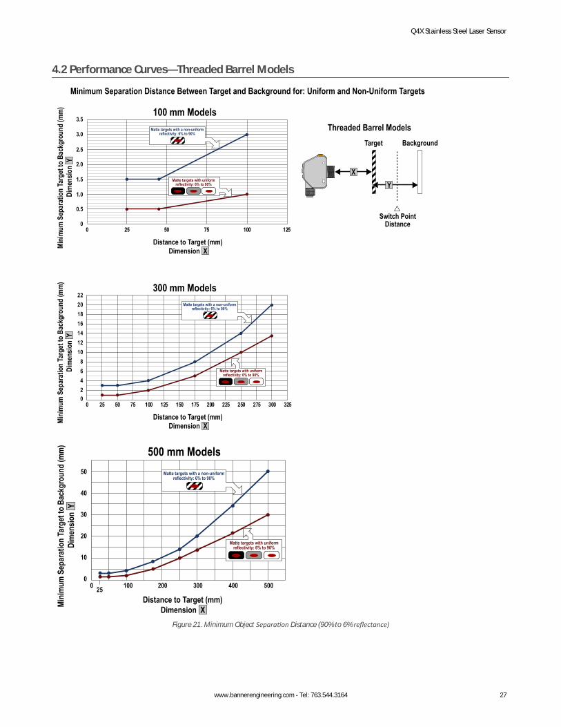
4.2 Performance Curves—Threaded Barrel Models
Minimum Separation Distance Between Target and Background for: Uniform and Non-Uniform Targets
100 mm Models
300 mm Models
Mini
mum
Sep
arat
ion
Targ
et to
Bac
kgro
und
(mm
)Di
men
sion
Y
Distance to Target (mm)Dimension X
Target
Switch Point Distance
Background
X
Y
02468
10121416182022
0 25 50 75 100 125 150 175 200 225 250 275 300 325
Matte targets with uniform reflectivity: 6% to 90%
Matte targets with a non-uniform reflectivity: 6% to 90%
Mini
mum
Sep
arat
ion
Targ
et to
Bac
kgro
und
(mm
)Di
men
sion
Y
Distance to Target (mm)Dimension X
0
0.5
1.0
1.5
2.0
2.5
3.0
3.5
0 25 50 75 100 125
Matte targets with a non-uniform reflectivity: 6% to 90%
Matte targets with uniform reflectivity: 6% to 90%
Threaded Barrel Models
500 mm Models
Mini
mum
Sep
arat
ion
Targ
et to
Bac
kgro
und
(mm
)Di
men
sion
Y
Distance to Target (mm)Dimension X
0
10
20
30
40
50
0 10025 200 300 400 500
Matte targets with uniform reflectivity: 6% to 90%
Matte targets with a non-uniform reflectivity: 6% to 90%
Figure 21. Minimum Object Separation Distance (90% to 6% reflectance)
Q4X Stainless Steel Laser Sensor
www.bannerengineering.com - Tel: 763.544.3164 27
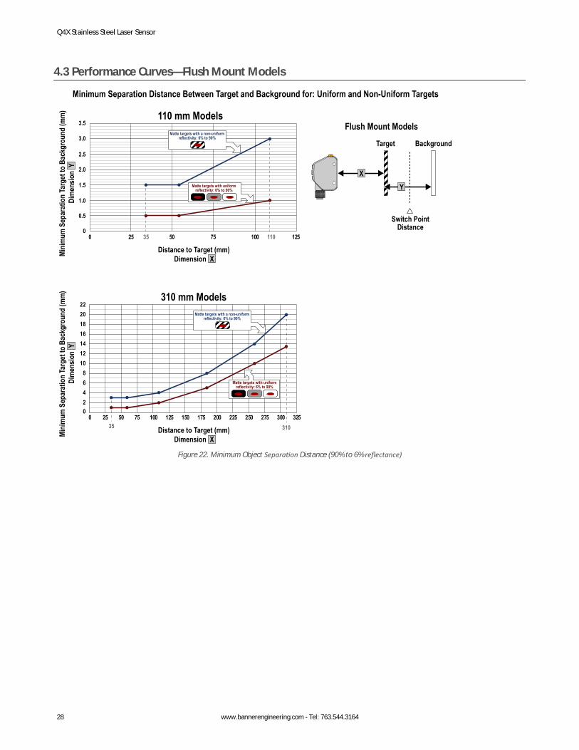
4.3 Performance Curves—Flush Mount Models
Minimum Separation Distance Between Target and Background for: Uniform and Non-Uniform Targets
110 mm Models
310 mm Models
Mini
mum
Sep
arat
ion
Targ
et to
Bac
kgro
und
(mm
)Di
men
sion
Y
Distance to Target (mm)Dimension X
02468
10121416182022
0 25 50 75 100 125 150 175 200 225 250 275 300 325
Matte targets with uniform reflectivity: 6% to 90%
Target
Switch Point Distance
Background
X
Y
Matte targets with a non-uniform reflectivity: 6% to 90%
Mini
mum
Sep
arat
ion
Targ
et to
Bac
kgro
und
(mm
)Di
men
sion
Y
Distance to Target (mm)Dimension X
0
0.5
1.0
1.5
2.0
2.5
3.0
3.5
0 25 35 50 75 100 125
Matte targets with a non-uniform reflectivity: 6% to 90%
Matte targets with uniform reflectivity: 6% to 90%
Flush Mount Models
110
35 310
Figure 22. Minimum Object Separation Distance (90% to 6% reflectance)
Q4X Stainless Steel Laser Sensor
28 www.bannerengineering.com - Tel: 763.544.3164
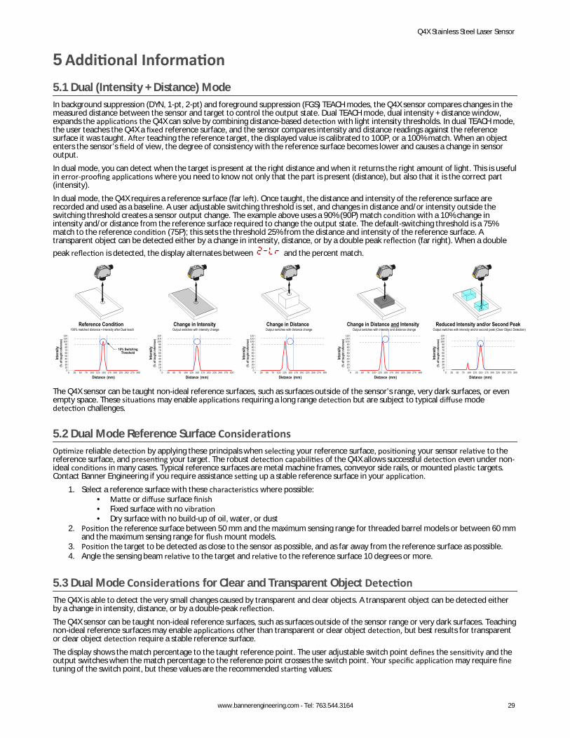
5 Additional Information5.1 Dual (Intensity + Distance) ModeIn background suppression (DYN, 1-pt, 2-pt) and foreground suppression (FGS) TEACH modes, the Q4X sensor compares changes in themeasured distance between the sensor and target to control the output state. Dual TEACH mode, dual intensity + distance window,expands the applications the Q4X can solve by combining distance-based detection with light intensity thresholds. In dual TEACH mode,the user teaches the Q4X a fixed reference surface, and the sensor compares intensity and distance readings against the referencesurface it was taught. After teaching the reference target, the displayed value is calibrated to 100P, or a 100% match. When an objectenters the sensor’s field of view, the degree of consistency with the reference surface becomes lower and causes a change in sensoroutput.In dual mode, you can detect when the target is present at the right distance and when it returns the right amount of light. This is usefulin error-proofing applications where you need to know not only that the part is present (distance), but also that it is the correct part(intensity).In dual mode, the Q4X requires a reference surface (far left). Once taught, the distance and intensity of the reference surface arerecorded and used as a baseline. A user adjustable switching threshold is set, and changes in distance and/or intensity outside theswitching threshold creates a sensor output change. The example above uses a 90% (90P) match condition with a 10% change inintensity and/or distance from the reference surface required to change the output state. The default-switching threshold is a 75%match to the reference condition (75P); this sets the threshold 25% from the distance and intensity of the reference surface. Atransparent object can be detected either by a change in intensity, distance, or by a double peak reflection (far right). When a doublepeak reflection is detected, the display alternates between and the percent match.
Reference Condition
0102030405060708090
100110120
0 25 50 75 100 125 150 175 200 225 250 275 300
10% SwitchingThreshold
100% matched distance + Intensity after Dual teach
Inten
sity
(% o
f tau
ght r
efer
ence
)
Distance (mm)
Change in Intensity
0102030405060708090
100110120
0 25 50 75 100 125 150 175 200 225 250 275 300
Output switches with intensity change
Inten
sity
(% o
f tau
ght r
efer
ence
)
Distance (mm)
Change in Distance
0102030405060708090
100110120
0 25 50 75 100 125 150 175 200 225 250 275 300
Output switches with distance change
Inten
sity
(% o
f tau
ght r
efer
ence
)
Distance (mm)
Change in Distance and Intensity
0102030405060708090
100110120
0 25 50 75 100 125 150 175 200 225 250 275 300
Output switches with intensity and distance change
Inten
sity
(% o
f tau
ght r
efer
ence
)
Distance (mm)
Reduced Intensity and/or Second Peak
0102030405060708090
100110120
0 25 50 75 100 125 150 175 200 225 250 275 300
Output switches with intensity and/or second peak (Clear Object Detection)
Inten
sity
(% o
f tau
ght r
efer
ence
)
Distance (mm)
The Q4X sensor can be taught non-ideal reference surfaces, such as surfaces outside of the sensor’s range, very dark surfaces, or evenempty space. These situations may enable applications requiring a long range detection but are subject to typical diffuse modedetection challenges.
5.2 Dual Mode Reference Surface ConsiderationsOptimize reliable detection by applying these principals when selecting your reference surface, positioning your sensor relative to thereference surface, and presenting your target. The robust detection capabilities of the Q4X allows successful detection even under non-ideal conditions in many cases. Typical reference surfaces are metal machine frames, conveyor side rails, or mounted plastic targets.Contact Banner Engineering if you require assistance setting up a stable reference surface in your application.
1. Select a reference surface with these characteristics where possible:• Matte or diffuse surface finish• Fixed surface with no vibration• Dry surface with no build-up of oil, water, or dust
2. Position the reference surface between 50 mm and the maximum sensing range for threaded barrel models or between 60 mmand the maximum sensing range for flush mount models.
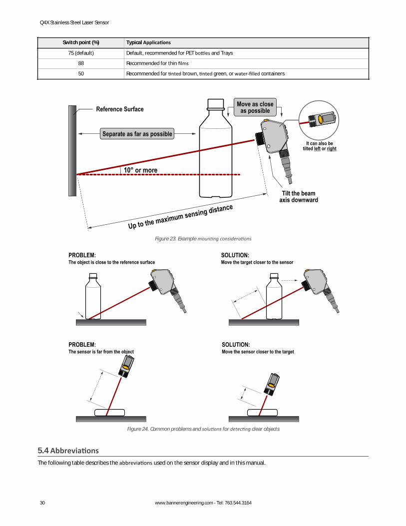
3. Position the target to be detected as close to the sensor as possible, and as far away from the reference surface as possible.4. Angle the sensing beam relative to the target and relative to the reference surface 10 degrees or more.
5.3 Dual Mode Considerations for Clear and Transparent Object DetectionThe Q4X is able to detect the very small changes caused by transparent and clear objects. A transparent object can be detected eitherby a change in intensity, distance, or by a double-peak reflection.The Q4X sensor can be taught non-ideal reference surfaces, such as surfaces outside of the sensor range or very dark surfaces. Teachingnon-ideal reference surfaces may enable applications other than transparent or clear object detection, but best results for transparentor clear object detection require a stable reference surface.The display shows the match percentage to the taught reference point. The user adjustable switch point defines the sensitivity and theoutput switches when the match percentage to the reference point crosses the switch point. Your specific application may require finetuning of the switch point, but these values are the recommended starting values:
Q4X Stainless Steel Laser Sensor
www.bannerengineering.com - Tel: 763.544.3164 29
Switch point (%) Typical Applications
75 (default) Default, recommended for PET bottles and Trays
88 Recommended for thin films
50 Recommended for tinted brown, tinted green, or water-filled containers
10° or more
Up to the maximum sensing distance
Reference Surface
Separate as far as possible
Move as closeas possible
Tilt the beamaxis downward
It can also betilted left or right
Figure 23. Example mounting considerations
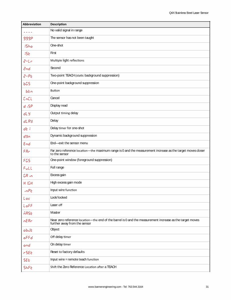
The object is close to the reference surfacePROBLEM:
Move the target closer to the sensorSOLUTION:
The sensor is far from the objectPROBLEM:
Move the sensor closer to the targetSOLUTION:
Figure 24. Common problems and solutions for detecting clear objects
5.4 AbbreviationsThe following table describes the abbreviations used on the sensor display and in this manual.
Q4X Stainless Steel Laser Sensor
30 www.bannerengineering.com - Tel: 763.544.3164
Abbreviation Description
No valid signal in range
The sensor has not been taught
One-shot
First
Multiple light reflections
Second
Two-point TEACH (static background suppression)
One-point background suppression
Button
Cancel
Display read
Output timing delay
Delay
Delay timer for one-shot
Dynamic background suppression
End—exit the sensor menu
Far zero reference location—the maximum range is 0 and the measurement increase as the target moves closerto the sensor
One-point window (foreground suppression)
Full range
Excess gain
High excess gain mode
Input wire function
Lock/locked
Laser off
Master
Near zero reference location—the end of the barrel is 0 and the measurement increase as the target movesfurther away from the sensor
Object
Off delay timer
On delay timer
Reset to factory defaults
Input wire = remote teach function
Shift the Zero Reference Location after a TEACH
Q4X Stainless Steel Laser Sensor
www.bannerengineering.com - Tel: 763.544.3164 31

Abbreviation Description
Slave
Response speed
Standard excess gain mode
Start
Stop
TEACH process selection
Unlock/unlocked
Saturated signal (too much light)
Zero—select the zero reference location
Q4X Stainless Steel Laser Sensor
32 www.bannerengineering.com - Tel: 763.544.3164
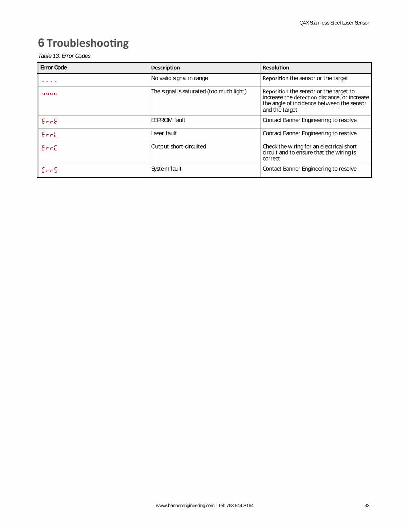
6 TroubleshootingTable 13: Error Codes
Error Code Description Resolution
No valid signal in range Reposition the sensor or the target
The signal is saturated (too much light) Reposition the sensor or the target toincrease the detection distance, or increasethe angle of incidence between the sensorand the target
EEPROM fault Contact Banner Engineering to resolve
Laser fault Contact Banner Engineering to resolve
Output short-circuited Check the wiring for an electrical shortcircuit and to ensure that the wiring iscorrect
System fault Contact Banner Engineering to resolve
Q4X Stainless Steel Laser Sensor
www.bannerengineering.com - Tel: 763.544.3164 33
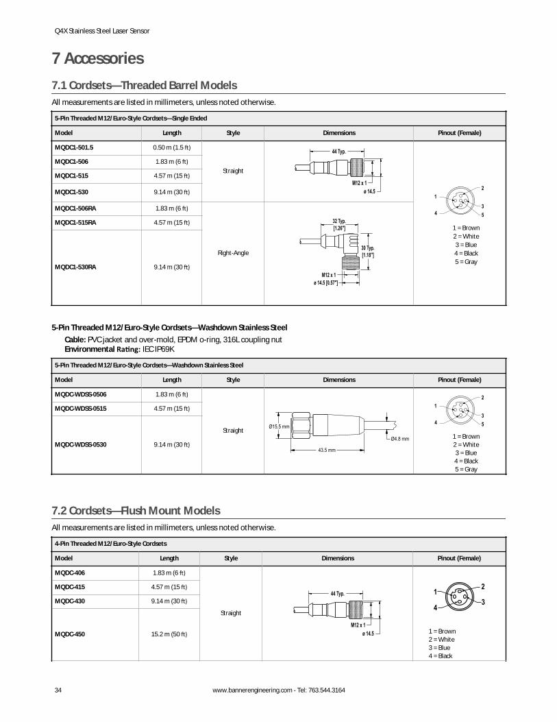
7 Accessories7.1 Cordsets—Threaded Barrel ModelsAll measurements are listed in millimeters, unless noted otherwise.
5-Pin Threaded M12/Euro-Style Cordsets—Single Ended
Model Length Style Dimensions Pinout (Female)
MQDC1-501.5 0.50 m (1.5 ft)
Straight
44 Typ.
ø 14.5M12 x 1
2
34
1
5
1 = Brown2 = White3 = Blue4 = Black5 = Gray
MQDC1-506 1.83 m (6 ft)
MQDC1-515 4.57 m (15 ft)
MQDC1-530 9.14 m (30 ft)
MQDC1-506RA 1.83 m (6 ft)
Right-Angle
32 Typ.[1.26"]
30 Typ.[1.18"]
ø 14.5 [0.57"]M12 x 1
MQDC1-515RA 4.57 m (15 ft)
MQDC1-530RA 9.14 m (30 ft)
5-Pin Threaded M12/Euro-Style Cordsets—Washdown Stainless SteelCable: PVC jacket and over-mold, EPDM o-ring, 316L coupling nutEnvironmental Rating: IEC IP69K
5-Pin Threaded M12/Euro-Style Cordsets—Washdown Stainless Steel
Model Length Style Dimensions Pinout (Female)
MQDC-WDSS-0506 1.83 m (6 ft)
Straight
43.5 mm
Ø4.8 mm
Ø15.5 mm
2
34
1
5
1 = Brown2 = White3 = Blue4 = Black5 = Gray
MQDC-WDSS-0515 4.57 m (15 ft)
MQDC-WDSS-0530 9.14 m (30 ft)
7.2 Cordsets—Flush Mount ModelsAll measurements are listed in millimeters, unless noted otherwise.
4-Pin Threaded M12/Euro-Style Cordsets
Model Length Style Dimensions Pinout (Female)
MQDC-406 1.83 m (6 ft)
Straight
44 Typ.
ø 14.5M12 x 1
2
34
1
1 = Brown2 = White3 = Blue4 = Black
MQDC-415 4.57 m (15 ft)
MQDC-430 9.14 m (30 ft)
MQDC-450 15.2 m (50 ft)
Q4X Stainless Steel Laser Sensor
34 www.bannerengineering.com - Tel: 763.544.3164
4-Pin Threaded M12/Euro-Style Cordsets
Model Length Style Dimensions Pinout (Female)
MQDC-406RA 1.83 m (6 ft)
Right-Angle
32 Typ.[1.26"]
30 Typ.[1.18"]
ø 14.5 [0.57"]M12 x 1
MQDC-415RA 4.57 m (15 ft)
MQDC-430RA 9.14 m (30 ft)
MQDC-450RA 15.2 m (50 ft)
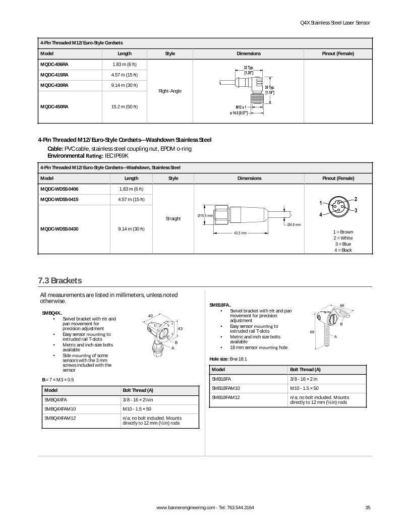
4-Pin Threaded M12/Euro-Style Cordsets—Washdown Stainless SteelCable: PVC cable, stainless steel coupling nut, EPDM o-ringEnvironmental Rating: IEC IP69K
4-Pin Threaded M12/Euro-Style Cordsets—Washdown, Stainless Steel
Model Length Style Dimensions Pinout (Female)
MQDC-WDSS-0406 1.83 m (6 ft)
Straight
43.5 mm
Ø4.8 mm
Ø15.5 mm
2
34
1
1 = Brown2 = White3 = Blue4 = Black
MQDC-WDSS-0415 4.57 m (15 ft)
MQDC-WDSS-0430 9.14 m (30 ft)
7.3 BracketsAll measurements are listed in millimeters, unless notedotherwise.
SMBQ4X..• Swivel bracket with tilt and
pan movement forprecision adjustment
• Easy sensor mounting toextruded rail T-slots
• Metric and inch size boltsavailable
• Side mounting of somesensors with the 3 mmscrews included with thesensor
40
43
AB
B = 7 × M3 × 0.5
Model Bolt Thread (A)
SMBQ4XFA 3/8 - 16 × 2¼ in
SMBQ4XFAM10 M10 - 1.5 × 50
SMBQ4XFAM12 n/a; no bolt included. Mountsdirectly to 12 mm (½ in) rods
SMB18FA..• Swivel bracket with tilt and pan
movement for precisionadjustment
• Easy sensor mounting toextruded rail T-slots
• Metric and inch size boltsavailable
• 18 mm sensor mounting hole
66
69A
B
Hole size: B=ø 18.1
Model Bolt Thread (A)
SMB18FA 3/8 - 16 × 2 in
SMB18FAM10 M10 - 1.5 × 50
SMB18FAM12 n/a; no bolt included. Mountsdirectly to 12 mm (½ in) rods
Q4X Stainless Steel Laser Sensor
www.bannerengineering.com - Tel: 763.544.3164 35
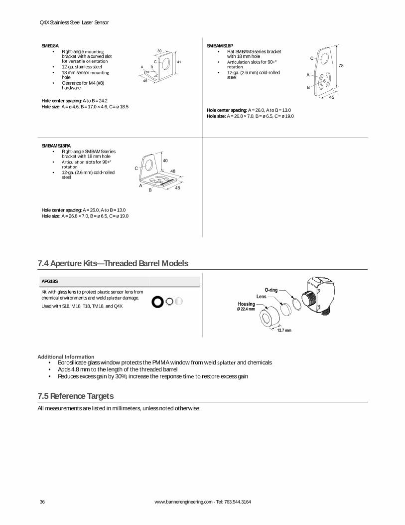
SMB18A• Right-angle mounting
bracket with a curved slotfor versatile orientation
• 12-ga. stainless steel• 18 mm sensor mounting
hole• Clearance for M4 (#8)
hardware
30
41
46
A BC
Hole center spacing: A to B = 24.2Hole size: A = ø 4.6, B = 17.0 × 4.6, C = ø 18.5
SMBAMS18P• Flat SMBAMS series bracket
with 18 mm hole• Articulation slots for 90+°
rotation• 12-ga. (2.6 mm) cold-rolled
steel
45
78
A
B
C
Hole center spacing: A = 26.0, A to B = 13.0Hole size: A = 26.8 × 7.0, B = ø 6.5, C = ø 19.0
SMBAMS18RA• Right-angle SMBAMS series
bracket with 18 mm hole• Articulation slots for 90+°
rotation• 12-ga. (2.6 mm) cold-rolled
steel48
45
40
AB
C
Hole center spacing: A = 26.0, A to B = 13.0Hole size: A = 26.8 × 7.0, B = ø 6.5, C = ø 19.0
7.4 Aperture Kits—Threaded Barrel Models
APG18S
Kit with glass lens to protect plastic sensor lens fromchemical environments and weld splatter damage.
Used with S18, M18, T18, TM18, and Q4X
HousingØ 22.4 mm
12.7 mm
LensO-ring
Additional Information• Borosilicate glass window protects the PMMA window from weld splatter and chemicals• Adds 4.8 mm to the length of the threaded barrel• Reduces excess gain by 30%; increase the response time to restore excess gain
7.5 Reference TargetsAll measurements are listed in millimeters, unless noted otherwise.
Q4X Stainless Steel Laser Sensor
36 www.bannerengineering.com - Tel: 763.544.3164

BRT-Q4X-60X18• Reference target for clear object
detection or dual mode applications• FDA grade acetal material
2 xø4.5
186
60 BRT-Q4X-60X50• Reference target for clear object
detection or dual mode applications• FDA grade acetal material
2 xø4.6
50
6
60
Q4X Stainless Steel Laser Sensor
www.bannerengineering.com - Tel: 763.544.3164 37
8 Contact UsCorporate Headquarters
Address:Banner Engineering Corporate9714 Tenth Avenue NorthMinneapolis, Minnesota 55441, USA
Phone: +1 763 544 3164Website: www.bannerengineering.com
Europe
Address:Banner Engineering EMEAPark Lane Culliganlaan 2FDiegem B-1831, Belgium
Phone: +32 (0)2 456 0780Website: www.bannerengineering.com/euEmail: [email protected]
Turkey
Address:Banner Engineering TurkeyBarbaros Mah. Uphill Court Towers A Blok D:4934746 Batı Ataşehir Istanbul Türkiye
Phone: +90 216 688 8282Website: www.bannerengineering.com.trEmail: [email protected]
India
Address:Banner Engineering India Pune Head QuartersOffice No. 1001, 10th Floor Sai Capital, Opp. ICC Senapati Bapat RoadPune 411016, India
Phone: +91 (0) 206 640 5624Website: www.bannerengineering.co.inEmail: [email protected]
Mexico
Address:Banner Engineering de Mexico Monterrey Head OfficeEdificio VAO Av. David Alfaro Siqueiros No.103 Col. Valle Oriente C.P.66269San Pedro Garza Garcia, Nuevo Leon, Mexico
Phone: +52 81 8363 2714 or 01 800 BANNERE (toll free)Website: www.bannerengineering.com.mxEmail: [email protected]
Brazil
Address:Banner do BrasilRua Barão de Teffé nº 1000, sala 54Campos Elíseos, Jundiaí - SP, CEP.: 13208-761, Brasil
Phone: +1 763 544 3164Website: www.bannerengineering.com.brEmail: [email protected]
China
Address:Banner Engineering Shanghai Rep OfficeXinlian Scientific Research Building Level 12, Building 21535 Hongmei Road, Shanghai 200233, China
Phone: +86 212 422 6888Website: www.bannerengineering.com.cnEmail: [email protected]
Japan
Address:Banner Engineering JapanCent-Urban Building 305 3-23-15 Nishi-Nakajima Yodogawa-KuOsaka 532-0011, Japan
Phone: +81 (0)6 6309 0411Website: www.bannerengineering.co.jpEmail: [email protected]
Taiwan
Address:Banner Engineering Taiwan8F-2, No. 308 Section 1, Neihu RoadTaipei 114, Taiwan
Phone: +886 (0)2 8751 9966Website: www.bannerengineering.com.twEmail: [email protected]
Q4X Stainless Steel Laser Sensor
38 www.bannerengineering.com - Tel: 763.544.3164

9 Banner Engineering Corp. Limited WarrantyBanner Engineering Corp. warrants its products to be free from defects in material and workmanship for one year following the date of shipment. Banner Engineering Corp. will repair orreplace, free of charge, any product of its manufacture which, at the time it is returned to the factory, is found to have been defective during the warranty period. This warranty does not coverdamage or liability for misuse, abuse, or the improper application or installation of the Banner product.THIS LIMITED WARRANTY IS EXCLUSIVE AND IN LIEU OF ALL OTHER WARRANTIES WHETHER EXPRESS OR IMPLIED (INCLUDING, WITHOUT LIMITATION, ANY WARRANTY OFMERCHANTABILITY OR FITNESS FOR A PARTICULAR PURPOSE), AND WHETHER ARISING UNDER COURSE OF PERFORMANCE, COURSE OF DEALING OR TRADE USAGE.This Warranty is exclusive and limited to repair or, at the discretion of Banner Engineering Corp., replacement. IN NO EVENT SHALL BANNER ENGINEERING CORP. BE LIABLE TO BUYER OR ANYOTHER PERSON OR ENTITY FOR ANY EXTRA COSTS, EXPENSES, LOSSES, LOSS OF PROFITS, OR ANY INCIDENTAL, CONSEQUENTIAL OR SPECIAL DAMAGES RESULTING FROM ANY PRODUCTDEFECT OR FROM THE USE OR INABILITY TO USE THE PRODUCT, WHETHER ARISING IN CONTRACT OR WARRANTY, STATUTE, TORT, STRICT LIABILITY, NEGLIGENCE, OR OTHERWISE.Banner Engineering Corp. reserves the right to change, modify or improve the design of the product without assuming any obligations or liabilities relating to any product previouslymanufactured by Banner Engineering Corp. Any misuse, abuse, or improper application or installation of this product or use of the product for personal protection applications when theproduct is identified as not intended for such purposes will void the product warranty. Any modifications to this product without prior express approval by Banner Engineering Corp will void theproduct warranties. All specifications published in this document are subject to change; Banner reserves the right to modify product specifications or update documentation at any time.Specifications and product information in English supersede that which is provided in any other language. For the most recent version of any documentation, refer to: www.bannerengineering.com.
Q4X Stainless Steel Laser Sensor
www.bannerengineering.com - Tel: 763.544.3164 39