qpi-12 filter evaluation board - vicor corporation corporation † qpi-12-cb1 data sheet rev. 1.0...
TRANSCRIPT

Picor Corporation • www.picorpower.com QPI-12-CB1 Data Sheet Rev. 1.0 Page 1 of 6
IntroductionThe QPI-12-CB1 carrier board is an evaluation board platform designed to demonstrate the EMI capabilities of a QPI-12LZ filter, with any combinationof 48 V input PRM / VTM or BCM evaluation boards. The QPI-12-CB1 board includes a pre-mounted filteralong with some additional components necessary todemonstrate the full functionality of the filter, alongwith mounting areas for V•I Chip evaluation boards.This User’s Guide provides basic instructions forassembly and use of the board. Further information onthe functionality of the V•I Chip boards, as well as theQPI-12LZ can be found in the V•I Chip Evaluation BoardUser’s Guide as well as the V•I Chip and QPI-12LZ data sheets.
QPI-12LZ Product DescriptionThe QPI-12LZ EMI filter is specifically designed to attenuateconducted common-mode (CM) and differential-mode(DM) noise of Vicor’s V•I Chip products to comply with theCISPR22 standard requirements for conducted noisemeasurements. The filter is designed to operate up to 80Vdc continuous, with a 100 Vdc surge for 100 ms, andsupports 7 A loads up to 60°C without derating.
Designed for the telecom bus range, the V•I Chip EMI Filtersupports the PICMG
®3.0 specification for filtering system
boards to the EN55022 Class B limits.
QPI-12-CB1QUIETPOWER™
QPI-12LZ Filter Carrier Board for 48 V V•I Chip EMI Evaluation
®
ContentsIntroduction . . . . . . . . . . . . . . . . . . . . . . . . . . . Page 1
Board overview . . . . . . . . . . . . . . . . . . . . . . . . Page 2
Bill of materials . . . . . . . . . . . . . . . . . . . . . . . . Page 2
Schematic . . . . . . . . . . . . . . . . . . . . . . . . . . . . . Page 2
Board assembly . . . . . . . . . . . . . . . . . . . . . . . . Page 3
V•I Chip mounting configurations . . . . . . . . . Page 3
EMI bypass configurations. . . . . . . . . . . . . . . . Page 4
EMI performance and test set up . . . . . . . . . . Page 4
Typical EMI performance. . . . . . . . . . . . . . . . . Page 5
Mechanical drawings . . . . . . . . . . . . . . . . . . . . Page 6
Ordering information . . . . . . . . . . . . . . . . . . . Page 6
Additional resources . . . . . . . . . . . . . . . . . . . . Page 6 QPI-12-CB1 carrier board featuringthe QPI-12LZ EMI filter

Picor Corporation • www.picorpower.com QPI-12-CB1 Data Sheet Rev. 1.0 Page 2 of 6
C1
QPI-12LZ
C2
Shield Connection CY5 – CY10
For BCMPlacement
For VTMPlacement
For PRMPlacement Placement
Figure 1 – QPI-12-CB1 board overview
Shield
C22.2 uF
VIN+
VIN-
Shield
BUS-1
SHIE
LD2
SHIE
LD3
EMI- 4EMI- 5
EMI+ 6EMI+ 7BUS+8BUS+9
BUS-10
QPI-12LZ
Vin-
Vin+ +In
-In
47 uFC1
VIN-A
VIN+APRM+1
BCM+2
BCM-3
PRM-4
VTM_IN+ 5
VTM_IN- 8
VTM_OUT+ 6
VTM_OUT- 7
Carrier
CY14.7 nF
CY24.7 nF
CY3
4.7nF
CY4
4.7 nF
CY54.7 nF
CY64.7 nF
CY74.7 nF
CY84.7 nF
CY94.7 nF
CY104.7 nF
VTM_IN+
VTM_IN-
VTM_OUT-
VTM_OUT+
Vout-
Vout+
1
2JVIN+
1
2JVIN-
1
2
3JVOUT+
1
2
3JVOUT-
VTM_OUT+
VTM_OUT-
1
2
3JBCM-
1
2
3JBCM+VTM_IN+
VTM_IN-
Figure 2 – QPI-12-CB1 carrier board schematic
Bill of MaterialsRef Designator DescriptionQPI QPI-12LZ SiP
CI Capacitor, electrolytic, 47 uF, 100 V
C2 Capacitor, ceramic, 2.2 uF, 100 V
CY5 thru CY10 Capacitor, X7R ceramic, 4.7 nF, 1,000 V
Hardware Machine screw, pan head, 0.373", 1/2" long, #10-24 thread
Hardware Machine nut, hex, 3/8", #10-24 thread
CY1 thru CY4 Optional Y-Cap configuration (not populated)
As noted above: CY1 thru CY4 not populated.
Picor Corporation • www.picorpower.com QPI-12-CB1 Data Sheet Rev. 1.0 Page 3 of 6
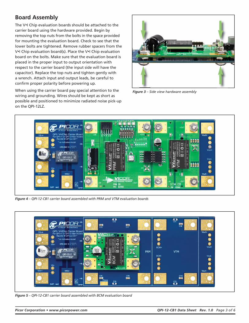
Board AssemblyThe V•I Chip evaluation boards should be attached to thecarrier board using the hardware provided. Begin byremoving the top nuts from the bolts in the space providedfor mounting the evaluation board. Check to see that thelower bolts are tightened. Remove rubber spacers from theV•I Chip evaluation board(s). Place the V•I Chip evaluationboard on the bolts. Make sure that the evaluation board isplaced in the proper input to output orientation withrespect to the carrier board (the input side will have thecapacitor). Replace the top nuts and tighten gently with a wrench. Attach input and output leads, be careful toconfirm proper polarity before powering up.
When using the carrier board pay special attention to thewiring and grounding. Wires should be kept as short aspossible and positioned to minimize radiated noise pick-upon the QPI-12LZ.
Figure 3 – Side view hardware assembly
Figure 4 – QPI-12-CB1 carrier board assembled with PRM and VTM evaluation boards
Figure 5 – QPI-12-CB1 carrier board assembled with BCM evaluation board

Picor Corporation • www.picorpower.com QPI-12-CB1 Data Sheet Rev. 1.0 Page 4 of 6
EMI Bypass ConfigurationsEMI bypass capacitors (“Y” capacitors) are an essentialelement in a switch-mode DC-DC filter application asthese capacitors provide a return path for common-mode noise currents to their source; so careful attentionto bypass capacitor implementation is essential for asuccessful EMI filter design. This carrier board ispreconfigured in a “base-plate” EMI topology, whichuses six “Y” capacitors (only four are actually used in aBCM configuration), as illustrated in Figure 7 below.This is the preferred topology for VI Chip applications.The carrier board can be manually reconfigured to an“open frame” topology, which uses four “Y” caps in aPRM/VTM combination (two for a BCM), as shown inFigure 8. The open-frame approach may attenuatecertain load dependent noise better than the base-platemethod. The carrier board provides an ideal test vehiclefor making a comparison between the two “Y”capacitor configurations. To reconfigure to “openframe” carefully remove capacitors CY5 through CY10and place four of those six capacitors in the positionsmarked as CY1 through CY4.
EMI Performance and Test Set UpThe EMI plots in Figures 9 through 14 are the total noisemeasurements, on both the positive and negative linesof the QPI-12LZ with various V•I Chip configurations,
BUS+ QPI+
BUS- QPI-
SH
IELD
QPI
VIN+ VOUT+
VIN- VOUT-
PRM
VIN+ VOUT+
VIN- VOUT-
VTM
CY5 CY6 CY9 CY7 CY10 CY8
C1
47 uF
LISN
LISN
PCB Plane Under Converter~1.25 m
Shielded Box
Shield Plane (Earth Ground)
PCB Board
BUSSUPPLY
Figure 7 – Basic EMI measurement setup for “base-plate” configuration.
BUS+ QPI+
BUS- QPI-
SH
IELD
QPI
VIN+ VOUT+
VIN- VOUT-
PRM
VIN+ VOUT+
VIN- VOUT-
VTM
CY3 CY1
CY4 CY2
C1
47 uF
LISN
LISN
PCB PlaneUnder Converter
~1.25 m
Shielded Box
Shield Plane (Earth Ground)
PCB Board
BUSSUPPLY
Figure 8 – Basic EMI measurement setup for “open-frame” configuration.
using the basic base-plate standard “Y” capconfiguration. Figure 7 shows the basic EMImeasurement set up that was used to achieve theseresults. Figure 8 shows the alternate set up method whenconverting to the open-frame approach.
In Figure 7 (base-plate method), capacitors CY5 throughCY10 represent the recirculation capacitors that areconnected to each of the four input and outputterminals, then are commoned to a shield plane that hasbeen created underneath the converter. Since the PRM/VTM pair is similar to a conventional converter, which issplit into to halves, two additional “Y” caps (CY7 andCY9) were added to the PRM’s output (the input to theVTM), referenced to the shield plane.
In Figure 8 (open-frame method), four “Y” capacitors areused (CY1 through CY4) rather than the two “Y” capsthat a conventional converter would require, once againbecause of the topology split created by the pair.
In a BCM application there is no topology split so the setup would require two fewer capacitors for eitherconfiguration. The open-frame method would only needone pair of input an output caps, referenced to theshield plane on either side of the BCM. And for open-frame method a pair of “Y” caps across the positiveinput to positive output, and negative input andnegative output would be sufficient.

Picor Corporation • www.picorpower.com QPI-12-CB1 Data Sheet Rev. 1.0 Page 5 of 6
Figure 9 – Total noise QPI-12LZ* with 48 V input PRM and 3V output VTM. 3.27 A input current. 160 W output load.
Figure 12 – Total noise QPI-12LZ* with 48 V input, 3 V output BCM.3.18 A input current. 160 W output load.
Figure 10 – Total noise QPI-12LZ* with 48 V input PRM and 12 V output VTM. 4.03 A input current. 180 W output load.
Figure 13 – Total noise QPI-12LZ* with 48 V input, 12 V output BCM. 3.75 A input current. 180 W output load.
Figure 11 – Total noise QPI-12LZ* with 48 V input PRM and 48 V output VTM. 3.45 A input current. 160 W output load.
* These EMI plots are actually based on QPI-10LZ, which includes the same filter elements but includes integrated hot-swap.
Figure 14 – Total noise QPI-12LZ* with 48 V input, 48 V output BCM. 3.20 A input current. 153 W output load.

Picor Corporation • www.picorpower.com QPI-12-CB1 Data Sheet Rev. 1.0 Page 6 of 6
5/08
Plane
Vout-
Vout+BCM+
BCM-
Vin+
Vin-
5/07 revC
+In
+In
-In
-In
BCM PRM VTM
QPI / V•IChip Carrier BoardFor QPI-11 or QPI-12 filter models
Reorder # QPI-xx-CB1** xx indicates model
C2
Vin+
DLEIHS-niV
C1
CY1
CY2
CY3
CY4
CY5
CY6
CY7 CY8
CY9 CY10
Vout+
Vout-
Carrier0.000
0.6500.8501.050
2.0502.1502.250
3.200
2.800
0.400
0.000
0.385
0.8501.0501.250
1.9502.1502.350
2.815
3.200 0.
000
0.25
0
0.85
0
5.10
0
5.60
0
7.20
0
7.95
0
2.50
0
0.00
0
2.43
5
4.58
5
QPI-12LZ
Figure 17 – Mechanical drawing for QPI-12-CB1
Carrier Board Part Number Compatible V•I Chip Evaluation Boards (sold separately)*
QPI-12-CB1 PRMs: P048F048T12AL-CB, P048F048T24AL-CB, P048F048T17AL-CB, P048F048T32AL-CB,
VTMs: All 48 V input models
BCMs: All 48 V input models
Ordering Information
* Some V•I Chip products exceed the current rating and therefore may not be compatible when operating at full load
Additional Resources Online
QPI-12LZ Data Sheethttp://vicorpower.com/picorpower/data_sheets/#input_filters
V•I Chip Data Sheets and User Guideshttp://vicorpower.com/products/vichip/