qrm project
TRANSCRIPT

MUFFAKHAM JAH COLLEGE OF ENGINEERING AND
TECHNOLOGY
PROJECT SEMINARPROJECT GUIDE: D.SRINIVAS RAO (ASSOCIATE HEAD)
BY : MD NASEERUDDIN SHAH 1604-11-736-072 IBRAHIM MD AMEENUDDIN 1604-11-736-075 MOHD JALEELUDDIN 1604-11-736-105 MD SOHAIL KURANI 1604-11-736-135

DESIGN , ANALYSIS AND FABRICATION OF
QUICK RETURN MECHANISM

Introduction Basic Concepts Defining the Problem Overcoming the Problem Design Analysis Fabrication Application Conclusion Project Plan Methodology Bibliography
INDEX
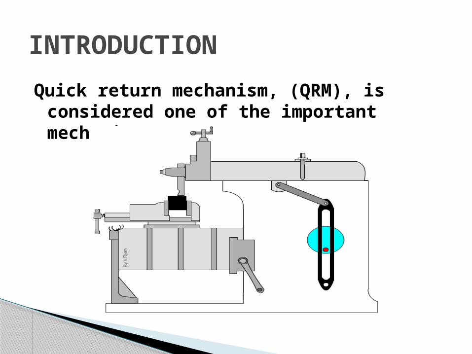
Quick return mechanism, (QRM), is considered one of the important mechanisms
INTRODUCTION

Mechanism : It transforms or transfer motion

Link: Machine element which moves relative to other elements (machine)
a) Rigid link b) Flexible link
c) Fluid link
Basic Definitions

Kinematic pair : When two links are joint they constitute a pair
Joints : Junction of links
Type of motions possible between links• Revolute• Sliding
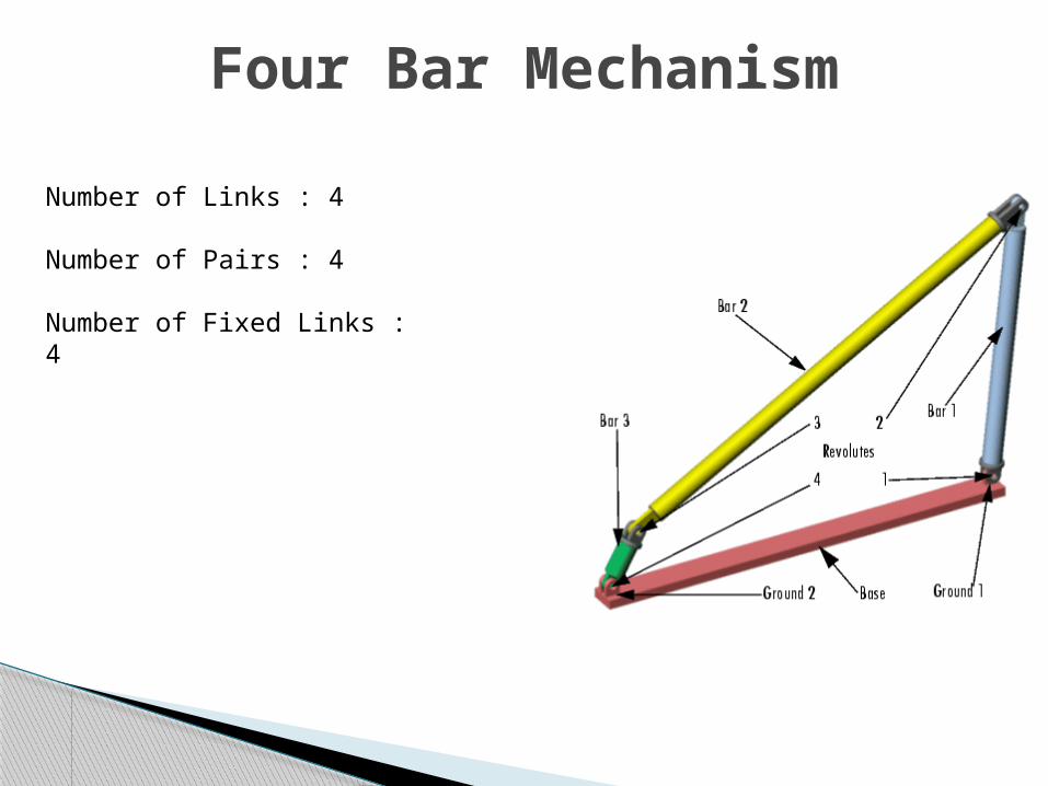
Four Bar Mechanism
Number of Links : 4
Number of Pairs : 4
Number of Fixed Links : 4

Slider Crank Mechanism
Modification of a basic four bar chain It consists of one sliding pair, three turning
pair

Method of obtaining different mechanisms by fixing different links in a kinematic chain
No. of Inversions possible = No. of links
No. of Inversions for four bar mechanism = 4
Inversions

Pendulum Pump Oscillating Cylinder Engine
Inversions of Slider Crank Chain

Rotary Internal Combustion Engine Crank and Slotted Lever Quick Return Mechanism

Whitworth Quick Return Mechanism

Lower Quick Return Ratio
Vibrations due to non linear velocity
Defining Problem
Rigid structure
Selection of material
Usage of Brass Bearings
Overcoming the problem

1.Forces acting on each link
2.Selecting materials
3.Suitable cross section
4.Link lengths
5.Machine power
Factors To Be Considered In Design
Design

Specifications and CalculationsStroke =120mm
Q.R =3
No.of strokes/min =50
Length AC = 40mm
Length BC = = = 56.57mm
Length AP = = =84.85mm
Length PR = 20mm

Dynamic Analysis
Calculation Of Forces
F6 = Τsteel *d* wF6 = 225*4*5F6 = 4500NF2 = F6
F5 =
F5 =
F5 =6364N
F4 = F5
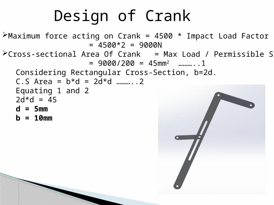
Design of CrankMaximum force acting on Crank = 4500 * Impact Load Factor
= 4500*2 = 9000NCross-sectional Area Of Crank = Max Load / Permissible Stress
= 9000/200 = 45mm2 ………..1
Considering Rectangular Cross-Section, b=2d. C.S Area = b*d = 2d*d ………..2Equating 1 and 22d*d = 45d = 5mmb = 10mm

Design Of Slotted BarMaximum Force acting on Slotted Bar = 6364 * Impact Load Factor
= 6364*2 = 12728NCross-sectional Area Of Crank = Max Load / Permissible Stress
= 12728/200 = 64mm2 ………..1Considering Rectangular Cross-Section, b=2d. C.S Area = b*d = 2d*d ………..2Equating 1 and 22d*d = 64d = 6mmb = 12mm

Power Calculations
From Specifications
Mean Velocity = Stroke length * No. of strokes/mm= 120*100= 12 m/min
Power = Cutting Force * Mean Velocity= 4500*(12/60)= 900 watts (1.2 HP)
Including Friction and Inertia Forces 2HP Motor is required.

Design For Power Transmission RPM of the Crank = No. of Strokes per minute
To Convert 1400rpm motor motion into 100rpm motion V-Belt drive
For given loads Phosphor Bronze Bushings of required thickness should be used at Pin Joints between the links
Due to large fluctuations in loads Vibrations are induced.
To minimize these Vibrations, Cast Iron or Wooden Frame should be used

Positional Analysis
Velocity Analysis
Acceleration Analysis
Force Analysis
Analysis of Quick Return Mechanism

Data Acquisition System
System takes the analog output from the various sensors and converts them into digital values.
Digital analogous value is fed into the processing unit.
The computer uses software called KDM (Kinematics and Dynamics Of Machines).
The needed values and their characteristic curves are plotted by the software and the output is recorded.

Analysis SoftwaresMotion simulation softwaresCAE tools
Catia UG-NX NX I-DEAS SolidWorks
To study planar mechanism kinematics MatLab Simulink MapleSim SolidWorks

Software Analysis Procedure
Modeling the linkage using the motion simulation application (SolidWorks).
Import the model into Ansys
Analyse the meshed model in Ansys (Structural)
Study planar mechanism kinematics (position, velocity and acceleration) of the model using SolidWorks
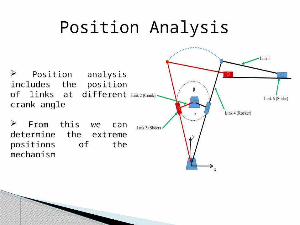
Position analysis includes the position of links at different crank angle
From this we can determine the extreme positions of the mechanism
Position Analysis

Velocity Analysis deals with variation in velocity of slider at different instances
Velocity Analysis

Ground length = 25mm
When crank radius tends to ground length , QRR tends to infinite
Crank radius = 10mm
When ground length tends to crank radius length , QRR tends to infinite
QRR Vs Crank Radius , QRR Vs Ground length

FabricationFabrication is an industrial term refers to building metal structures by cutting, machining and drilling.The fabrication of quick return mechanism unit involves:
Cutting
Drilling
Machining
Welding
Grinding
Carpentry work

Fabrication of Crank and Connecting Rod
The cutting operation can be carried out in workshop
For better accuracy , ease and surface finish shaping machine is preferred
Drilling of holes at ends of both sides
The holes are drilled with respect to suitable dimensions by using drilling machine

Fabrication of Slider Wood is cut in suitable dimensionThe carpentry operations are performed here
Fabrication of Frame A frame has to withstand the load of the crank as well as the connecting rod to avoid disturbanceA wood plank may be chosen to avoid breakage and also prevent noiseThe frame is to be cut into required dimensions using handsaw and chiselThe frame is to be tightened with the help of adhesives and screws for rigid supportGrinding may be done for a smooth surface finish

Machine tools
Shaping machines
Power-driven saws
Slotter machines
Applications

ConclusionThe purpose of the project is to design and construct a kinematic quick return device. Beginning with general research into quick return devices, the project has to follow a methodology of determining the design space, building a mathematical model and then implementing that model. The design process as a whole has to be experienced from start to finish and is to be incorporated as a multitude of different aspects of engineering. Designing this mechanism will be an excellent experience in tackling a design project where the majority of constraints are self-imposed. The final design produced will be an effective one. Hopefully, with a little work, the mechanism will be operational and seen by future kinematics students for years to come.

ACTIVITY TIMELINEProject Approval July
Consulting Guide & Background Research
August
Proposing A New Design August
Design Specifications September
Software Learning October & November
Software Implementation And Analysis
February
Presenting The Project March
PROJECT PLAN

Methodology Design of links
Analysis of links at various positions
Remodification of links (If required )
Implementation
Fabrication
Performance test

BIBLIOGRAPHY
Theory of Machines by R.S. Khurmi and J.K.Gupta
Design of Machine Elements by R.S. Khurmi and J.K.Gupta
Theory of Machines by Ratan
Manufacturing Technology by P N Rao
http://www.morldtechgossips.com/2012/05/fabrication-of-slider-crank-unit.html
