qse-io control interface - amazon s3 · qs system qse-io control interface 369374a 1 08.07.12...
TRANSCRIPT

R Specif icat ion Submittal page
Job Name:
Job Number:
Model Numbers:
QS System QSE-IO Control Interface
369374a 1 08.07.12
QSE-IO Control Interface
The QSE-IO contact closure interface provides integration with third-party equipment requiring contact closure input/output, including occupancy and vacancy sensors; motorized projection screens, skylights, and window shades; AV equipment; security systems; movable partition walls; and timeclocks. One QSE-IO interface provides five (5) dry contact closure outputs.For complete functionality, programming instructions, and detailed DIP switch settings, see the QSE-IO Programming Guide, PN 040391, at www.lutron.com/qs.
Key Features•IntegratesaGRAFIKEye® QS control system
with equipment that has contact-closure I/O•Providesfiveinputsandfivedrycontactclosure
outputs.•Providesbothnormallyopen(NO)andnormallyclosed(NC)contacts.
•MaybeprogrammedtocontrolorbecontrolledbyanycombinationofGRAFIKEye® QS control units or control any combination of Sivoia® QS window treatments on the QS link.
Compatible Components
The following devices are compatible with the QS link. Formoreinformationoneach,referto www.lutron.com/qs.
•GRAFIKEye® QS control units•seeTouch® QS wallstations•Sivoia® QS shades•QSInterfaces(contactclosure,Ethernet/RS232)•Quantum® system•EnergiSavrNodeTM units•QSSensorModule•QSKeyswitch
For Programming, see the QSE-IO Control Interface Programming Guide: PN 040391 at www.lutron.com/qs
Requirements•QSLinkPowerSupply,suchasa: -GRAFIKEye® QS -QSLinkpowersupply,suchastheQSPS-P1-1-50 -EnergiSavrNodeTM QS - Quantum® light management hub•QSCommunicationLink(IECPELV/NEC®Class2) (seeQSLinkWireSizestable)

R Specif icat ion Submittal page
Job Name:
Job Number:
Model Numbers:
QS System QSE-IO Control Interface
369374a 2 08.07.12
Specifications
Power•IECPELV/NEC®Class2•Operatingvoltage:12–24V 100mA
Regulatory Approvals•ULListed•cULListed•CEcompliant
QS Link Limits•TheQSwiredcommunicationslinkislimitedto100devicesand100zones.EachQSE-IOcontrolinterfacecountsas1deviceand2zones.
•EachQSE-IOcontrolinterfaceconsumes3powerdrawunits(PDU)ontheQSlink.RefertotheQSLinkPowerDrawUnitsSpecificationSubmittal(LutronPN369405,atwww.lutron.com)formoreinformation.
•ThemaximumwiringlengthfortheQSlinkis 2000ft(610m).
Environment•32to104°F(0to40°C).•Relativehumiditylessthan90%non-condensing.
Functionality and Operating Modes•Usingtheinputs,contactclosuresinotherequipmentcanoperatecontrolunitsto: –Selectscenes
–Adjustscenestoreflectstatusofmovablewalls –Toggleanycombinationofzonesinthesystem
between Off and a configurable preset value –Turnlightsonoroffand/ormoveshadesbasedon
room occupancy –Performspecialfunctionssuchassequencing,
panic, control lockout, or timeclock disable•Usingtheoutputs,sceneand/orzonechangesincontrolunitscan: –Triggeroutputstocontrolotherequipment. –Providestatusfeedbacktootherequipment.
•Usingtheinputs,contactclosuresinotherequipment can operate Sivoia® QS window treatmentsto: –Openorclose.
–Raise,lower,orstop. –Selectoneofthreeadjustablepresets.
•Usingtheoutputs,keypressesonQSwindowtreatmentkeypadsorGRAFIKEye® QS window treatmentbuttonscan: –Triggeroutputstoothermotorizedwindowtreatment
equipment.•Sceneselection •Occupancysensor•Zonetoggle •Shadeinput•Specialfunctions •Shadeoutput•Partitioning
Five Input Terminals•Acceptmaintainedinputsandmomentaryinputswith40msecminimumpulsetimes.
•Off-stateleakagecurrentmustbelessthan100µA.•Opencircuitvoltage:24V maximum.•Inputsmustbedrycontactclosure,solidstate,opencollector,oractive-low(NPN)/activehigh(PNP)output.
-OpencollectorNPNoractive-lowon-statevoltagemustbelessthan2V andsink3.0mA.
-OpencollectorPNPoractive-highon-statevoltagemustbegreaterthan12V andsource3.0mA.
Five Output Terminals•Provideselectablemaintainedormomentary
(1-second)outputs(IECPELV/NEC®Class2ratedonly).
•TheQSE-IOisnotratedtocontrolunclamped,inductive loads. Inductive loads include, but are not limited to, relays, solenoids, and motors. To control thesetypesofequipment,aflybackdiodemustbeused(DCvoltagesonly).See"TerminalLocations".
•Outputrelaysarenon-latching(ifrelaysareclosedandpower is lost, relays will open).
Status LEDs•FiveStatusLEDslightwhenassociatedoutputis
active (on).

R Specif icat ion Submittal page
Job Name:
Job Number:
Model Numbers:
QS System QSE-IO Control Interface
369374a 3 08.07.12
2.50(63.5)
3.75(95.3)
4.26(108.2)
5.26(133.6)
1.06(26.9)
Mountingholes
Terminal blocks on this side
LEDsandaddressingswitches on this side
Dimensions
Dimensionsareininches(mm)
0.34(8.6)dia.
0.18(4.6)dia.
0.18(4.6)dia.
0.25(6.4)
#6or#8(M3orM4)screw recommended
MountingHoleDetail
Mounting Options
Mounting ExamplesMountwhereterminalblocks,switches,andLEDsareaccessible. Strip 4in(10mm)ofinsulationfromwires. Each data link terminal will accept up to two 18AWG(1.0mm2)wires.ConnectwiringasshownintheWiringDiagram.Choosefromthefollowingmountingmethods:
1: Direct Wall Mounting
Mountthecontrolinterfacedirectlyonawall,asshowninMountingMethodsatright,usingscrews(notincluded).Whenmounting,providesufficientspace for connecting cables.
2: Rack Mounting
PlacetheunitcanintheLUT-19AV-1UAVrackusingscrews(notincluded).TheLUT-19AV-1Uwillholdupto four units.
3: Enclosed Wall Mounting
If conduit is desired for wiring, use the LUT-5x10-ENCtomountoneunit.
Note:Contactclosureoutputrelaysclickaudiblywhenswitching.Mountwherethiswillnotcauseinconvenience.
LUT-19AV-1U
2
LUT-5x10-ENC
5.26
4.263.75
2.50
1.06
Control Interface
Wall
1
3
R Specif icat ion Submittal page
Job Name:
Job Number:
Model Numbers:
QS System QSE-IO Control Interface
369374a 4 08.07.12
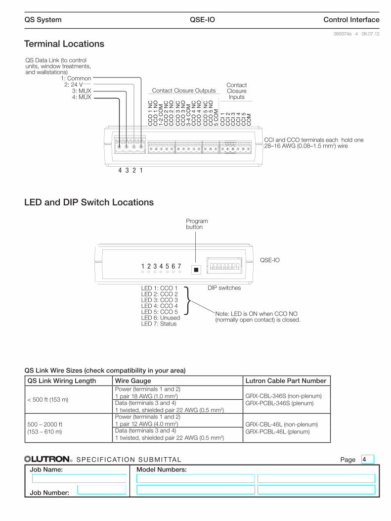
Terminal Locations
4 3 2 1
Rela
y 1
NCRe
lay
1 NO
Rela
y 1
& 2
Com
mon
Rela
y 2
NCRe
lay
2 NO
Rela
y 3
NCRe
lay
3 NO
Rela
y 3
& 4
Com
mon
Rela
y 4
NCRe
lay
4 NO
Rela
y 5
NCRe
lay
5 NO
Rela
y 5
Com
mon
Inpu
t 1In
put 2
Inpu
t 3In
put 4
Inpu
t 5Co
mm
on
CCIandCCOterminalseachholdone28–16AWG(0.08–1.5mm2) wire
QSDataLink(tocontrolunits, window treatments, and wallstations) 1:Common 2:24V 3:MUX
4:MUX
CC
O 1
NC
CC
O 1
NO
1-2
CO
MC
CO
2 N
CC
CO
2 N
OC
CO
3 N
CC
CO
3 N
O3-
4 C
OM
CC
O 4
NC
CC
O 4
NO
CC
O 5
NC
CC
O 5
NO
5 C
OM
CC
I 1C
CI 2
CC
I 3C
CI 4
CC
I 5C
OM
QSE-IO
Programbutton
1 2 3 4 5 6 7
DIPswitchesLED1:CCO1LED2:CCO2LED3:CCO3LED4:CCO4LED5:CCO5LED6:UnusedLED7:Status
Note:LEDisONwhenCCONO(normally open contact) is closed.
}
ContactClosureOutputsContactClosureInputs
LED and DIP Switch Locations
QS Link Wire Sizes (check compatibility in your area)
QS Link Wiring Length Wire Gauge Lutron Cable Part Number
<500ft(153m)
Power(terminals1and2)1pair18AWG(1.0mm2) GRX-CBL-346S(non-plenum)
GRX-PCBL-346S(plenum)Data(terminals3and4)1twisted,shieldedpair22AWG(0.5mm2)
500–2000ft(153–610m)
Power(terminals1and2)1pair12AWG(4.0mm2) GRX-CBL-46L(non-plenum)
GRX-PCBL-46L(plenum)Data(terminals3and4)1twisted,shieldedpair22AWG(0.5mm2)

R Specif icat ion Submittal page
Job Name:
Job Number:
Model Numbers:
QS System QSE-IO Control Interface
369374a 5 08.07.12
QS Link Wiring Methods (choose one)
Powered by GRAFIK Eye® QS Control Unit
Powered by a QS Link Power Supply
12
34
12
AB
C
1 2 3 4 5 6 L N
To additional wallstations/control interfaces
To additional wallstations/control interfaces
RearViewof GRAFIKEye® QS ControlUnit
RearViewof GRAFIKEye® QS ControlUnit
QS Link
QS Link
QSLink1:Common2:Power3:MUX4:MUX
DataLink:4:MUX3:MUX
SeeQSLink WireSizestableprevious page
IECPELV/NECClass2Powerwiring:2:Power1:CommonSeeQSLinkWireSizes table previous page
•SystemcommunicationusesIECPELV/NEC®Class2wiring.
•FollowalllocalandnationalelectricalcodeswheninstallingIECPELV/NEC®Class2wiringwithlinevoltage/mains wiring.
•Eachterminalacceptsuptotwo18AWG(1.0mm²)wires.
•Totallengthofcontrollinkmustnotexceed2000ft(610m).
•TypicalWireSizes:SeeQSLinkWireSizestable,previous page.
•Connecttheterminal1,3,and4connectionstoallcontrol units, wallstations, and control interfaces in theQSsystem.Forterminal2connectivity,pleaserefer to the wiring diagrams below.
•TheQSE-IOcontrolinterfacecanbepoweredbythefollowingdevices:
-GRAFIKEye® QS control unit -QSlinkpowersupply(QSPSmodelnumbers) - Quantum®LightManagementHub
(see Quantum® system documentation) -EnergiSavrNodeTM QS
4 3 2 1
LutronCable SeeQSLinkWireSizestableprevious page
QSPS-P1-1-50(providesupto8 power draw units)
To power source
(1)18AWG(1.0mm2) Common
(1)twistedpair22AWG(0.5mm2)

R Specif icat ion Submittal page
Job Name:
Job Number:
Model Numbers:
QS System QSE-IO Control Interface
369374a 6 08.07.12
Wiring Application Examples1 Lutron Occupancy Sensor Wired to 1 QSE-IO Device Input
QSE-IO Terminals
Occupancy Sensor
Power Pack(use model that corresponds to input voltage)
Hot
Neutral
Red (+20 - 24 V )Blue (signal)Black (common)Blue (signal)
Black (common)
Black
White
Red
Red
120 / 277 / 347 V 60 Hz230 V 50 / 60 Hz
CC
I1
CC
I2
CC
I3
CC
I4
CC
I5
CO
M
Power Pack(use model that corresponds to input voltage)
Blue (signal)
Black (common)
3 Lutron Occupancy Sensors Wired to 1 QSE-IO Device Input
QSE-IO Terminals
Occupancy Sensors
Hot
Neutral
Red (+20 - 24 V )Blue (signal)Black (common)
Black
White
Red
Red
120 / 277 / 347 V 60 Hz230 V 50 / 60 Hz
CC
I1
CC
I2
CC
I3
CC
I4
CC
I5
CO
M
Note: Occupancy sensors will not participate in partitioning logic.
More Than 3 Lutron Occupancy Sensors Wired to 1 QSE-IO Device Input
QSE-IO Terminals
Occupancy Sensors
Hot
Neutral
Red (+20 - 24 V )
Blue (signal)Black (common)
Red (+20 - 24 V )
Blue (signal)Black (common)
Black
White
Red
Red
120 / 277 / 347 V 60 Hz230 V 50 / 60 Hz
CC
I1
CC
I2
CC
I3
CC
I4
CC
I5
CO
M
Occupancy Sensors
Hot
Neutral
Black
White
Red
Red
120 / 277 / 347 V 60 Hz230 V 50 / 60 Hz
Blue (signal)
Black (common)
Blue (signal)
Black (common)
Power Pack(use model that corresponds to input voltage)
Power Pack(use model that corresponds to input voltage)
Note: Occupancy sensors will not participate in partitioning logic.

R Specif icat ion Submittal page
Job Name:
Job Number:
Model Numbers:
QS System QSE-IO Control Interface
369374a 7 08.07.12
Multiple Lutron Occupancy Sensors Wired to Multiple QSE-IO Device Inputs
QSE-IO Terminals
Occupancy Sensors
Hot
Neutral
Red(+20-24V )
Blue(signal)Black(common)
Red(+20-24V )
Blue(signal)Black(common)
Black
White
Red
Red
120/277/347V 60Hz230V 50/60Hz
CCI1
CCI2
CCI3
CCI4
CCI5
COM
Occupancy Sensors
PowerPack*
Hot
Neutral120/277/347V 60Hz230V 50/60Hz
Occupancy Sensors
PowerPack*
Neutral120/277/347V 60Hz230V 50/60Hz
Hot
Occupancy Sensor
PowerPack*
Neutral120/277/347V 60Hz230V 50/60Hz
Hot
Black
White
Red
Red
Black
White
Red
Red
Black
White
Red
Red
Black
White
Red
Red
Occupancy Sensor
PowerPack*
Neutral120/277/347V 60Hz230V 50/60Hz
Hot
Red(+20-24V )
Blue(signal)Black(common)
Red(+20-24V )
Blue(signal)Black(common)
Red(+20-24V )
Blue(signal)Black(common)
Wiring Application Examples
PowerPack*
*(usepowerpack model that corresponds to input voltage)
Note:Occupancysensorswillnotparticipateinpartitioninglogic.

R Specif icat ion Submittal page
Job Name:
Job Number:
Model Numbers:
QS System QSE-IO Control Interface
369374a 8 08.07.12
QSE-IO Operating Modes and DIP Switch Settings OverviewMode Dip Switch Contact Closures Invoke:
Configuration 3 4 5 6 7 8 Input 1 Input 2 Input 3 Input 4 Input 5 Inputs Outputs
Scene selection
Scene 1 Scene 2 Scene 3 Scene 4 Scene Off
Maintained or Momentary Maintained
Scene 5 Scene 6 Scene 7 Scene 8 Scene Off
Scene 9 Scene 10 Scene 11 Scene 12 Scene Off
Scene 13 Scene 14 Scene 15 Scene 16 Scene Off
Scene 1 Scene 2 Scene 3 Scene 4 Scene Off
Maintained or Momentary Momentary
Scene 5 Scene 6 Scene 7 Scene 8 Scene Off
Scene 9 Scene 10 Scene 11 Scene 12 Scene Off
Scene 13 Scene 14 Scene 15 Scene 16 Scene Off
Special (maintained)
Sequence 5–16
Zone lockout
Scene lockout
Panic mode Timeclock Maintained
MaintainedSpecial
(momentary)Sequence 5–16
Zone lockout
Scene lockout
Panic mode Timeclock Momentary
Special 2 (maintained)
Sequence 1–4
Zone lockout
Scene lockout
Panic mode
Afterhours mode Maintained
MaintainedSpecial 2
(momentary)Sequence 1–4
Zone lockout
Scene lockout
Panic mode
Afterhours mode Momentary
Shade input preset (“stop if moving”) Shade
openShade preset 1
Shade preset 2
Shade preset 3
Shade close
Maintained or Momentary Maintained
Shade input preset (no “stop if moving”)
Shade input (raise, lower, stop)
Shade open
Shade raise
Shade lower Shade stop Shade
closeMomentary or Maintained Maintained
Shade input dual group (“stop if moving”) Open
Group 1Close Group 1
Open Group 2
Close Group 2 — Maintained or
Momentary MaintainedShade input dual group (no “stop if moving”)
Shade input dual group (raise/lower)
Raise/Stop Group 1
Lower/Stop Group 1
Raise/Stop Group 2
Lower/Stop Group 2 — Momentary Momentary
Shade input toggle (“stop if moving”:
open/stop/close/stop)
Toggle Group 1
Toggle Group 2
Toggle Group 3
Toggle Group 4
Toggle Group 5 Momentary Momentary
Shade input toggle (no “stop if moving”:
open/close)
Toggle Group 1
Toggle Group 2
Toggle Group 3
Toggle Group 4
Toggle Group 5 Maintained Momentary
AC Shade output (maintained outputs)
Open Group 1
Stop Group 1
Close Group 1
Open Group 2
Close Group 2
Maintained or Momentary Maintained
AC Shade output (momentary stop)
Open Group 1
Stop Group 1 if moving
Close Group 1
Open Group 2
Close Group 2
Maintained or Momentary
Maintained (except 2, which is Momentary)
AC Shade output (momentary outputs)
Open Group 1
Stop Group 1 if moving
Close Group 1
Open Group 2
Close Group 2
Maintained or Momentary Momentary
Notes• ForACshadeswithonly2inputs(open/close),setDIPswitch1totheup/onpositiontoenablethefeature
thatmimics“stop”(assertsboth“open”and“close”CCOstogetherwhena“stop”commandisreceived).• TheQSE-IOprovidesnopower,onlyacontrolsignal,toACshades.Refertotheinstructionsthatcamewithyourshadesformore
information.
Legend: Up/On
Down/Off
s c e n es e l e c t i o n
s p e c i a l a n ds p e c i a l 2
z o n et o g g l e
z o n ec o n t r o l
h o t e lc o n � g u r a t i o n
i n t e g r a t i o nc o n � g u r a t i o n
s h a d es t u f f s
p a r t i t i o n i n go c c s e n s o r
3 4 5 6 7 8 3 4 5 6 7 8
3 4 5 6 7 8
3 4 5 6 7 8
3 4 5 6 7 8
3 4 5 6 7 8
3 4 5 6 7 8
3 4 5 6 7 8
3 4 5 6 7 8
3 4 5 6 7 8
3 4 5 6 7 8
3 4 5 6 7 8
3 4 5 6 7 8
3 4 5 6 7 8
3 4 5 6 7 8 3 4 5 6 7 8
3 4 5 6 7 8
3 4 5 6 7 8
3 4 5 6 7 8
3 4 5 6 7 8
3 4 5 6 7 8
3 4 5 6 7 8
3 4 5 6 7 8
3 4 5 6 7 8
3 4 5 6 7 8
3 4 5 6 7 8
3 4 5 6 7 8
3 4 5 6 7 8
3 4 5 6 7 8
3 4 5 6 7 8
3 4 5 6 7 8
3 4 5 6 7 8 3 4 5 6 7 8
3 4 5 6 7 8
3 4 5 6 7 8
3 4 5 6 7 8
3 4 5 6 7 8
3 4 5 6 7 8
3 4 5 6 7 8
3 4 5 6 7 8
3 4 5 6 7 8

R Specif icat ion Submittal page
Job Name:
Job Number:
Model Numbers:
QS System QSE-IO Control Interface
369374a 9 08.07.12
QSE-IO Operating Modes and DIP Switch Settings Overview (continued)Mode Dip Switch Contact Closures Invoke:
Configuration 3 4 5 6 7 8 Input 1 Input 2 Input 3 Input 4 Input 5 Inputs Outputs
Partitioning (momentary) Wall 1 Wall 2 Wall 3 Wall 4 Wall 5 Momentary Maintained
Partitioning (maintained) Wall 1 Wall 2 Wall 3 Wall 4 Wall 5 Maintained Maintained
Occupancy sensor (auto on/off) Generates events on occupancy and vacancy Maintained Maintained
Occupancy sensor (manual on/auto off) Generates events on vacancy only Maintained Maintained
Zone toggle (maintained) Toggle 1 Toggle 2 Toggle 3 Toggle 4 Toggle 5 Maintained
Maintained
Zone toggle (momentary) Toggle 1 Toggle 2 Toggle 3 Toggle 4 Toggle 5 Momentary
Zone toggle with raise/lower (maintained) Toggle 1 Toggle 2 Toggle 3 Raise Lower Maintained
Zone toggle with raise/lower (momentary) Toggle 1 Toggle 2 Toggle 3 Raise Lower Momentary
Zone control (maintained output)
Toggle 1 Toggle 2 Toggle 3 Toggle 4 Toggle 5 MaintainedMaintained
Toggle 1 Toggle 2 Toggle 3 Toggle 4 Toggle 5 Momentary
Zone control (momentary output)
Pulse 1 Pulse 2 Pulse 3 Pulse 4 Pulse 5 MaintainedMomentary
Pulse 1 Pulse 2 Pulse 3 Pulse 4 Pulse 5 Momentary
Zone control (pulsed output)
Pulse 1 Pulse 2 Pulse 3 Pulse 4 Pulse 5 MaintainedPulsed
Pulse 1 Pulse 2 Pulse 3 Pulse 4 Pulse 5 Momentary
Hotel configuration 1Service (make up room)
Privacy (do not disturb)
DoorbellStart/end afterhours mode
Toggle Scene 1/Off
1-3: Maintained or Momentary 4-5: Maintained
Maintained (except 3)
Hotel configuration 2Service (make up room)
Privacy (do not disturb)
DoorbellStart/end afterhours mode
Enable/disable Scene lockout
1-3: Maintained or Momentary 4-5: Maintained
Maintained (except 3)
Integration configuration Control output 1
Control output 2
Control output 3
Control output 4
Control output 5
Maintained or Momentary
Maintained or Momentary
Notes• Occupancysensor:Eachinputrepresents1sensor/groupofsensors.Responsetosensoreventisprogrammableattheassignedlighting
control.• “Momentary”outputpulseisoffixedduration(250msdefault).
“Pulsed”outputdurationcorrespondstoactivatingbuttonbeingheld/released.• Hotel:“Service”and“Privacy”aremutuallyexclusive;“Doorbell”islockedoutwhen“Privacy”isactive.• DIPswitch1mustbeup/ontoactivatethe"Start/EndAfterhours"featureonCCI4.• DIPswitch2mustbeup/ontoactivatethe"ToggleScene"or"SceneBlackout"featureonCCI5.• Occupancysensorswillnotparticipateinpartitioninglogic.
Legend: Up/On
Down/Off
s c e n es e l e c t i o n
s p e c i a l a n ds p e c i a l 2
z o n et o g g l e
z o n ec o n t r o l
h o t e lc o n � g u r a t i o n
i n t e g r a t i o nc o n � g u r a t i o n
s h a d es t u f f s
p a r t i t i o n i n go c c s e n s o r
3 4 5 6 7 8 3 4 5 6 7 8
3 4 5 6 7 8
3 4 5 6 7 8
3 4 5 6 7 8
3 4 5 6 7 8
3 4 5 6 7 8
3 4 5 6 7 8
3 4 5 6 7 8
3 4 5 6 7 8
3 4 5 6 7 8
3 4 5 6 7 8
3 4 5 6 7 8
3 4 5 6 7 8
3 4 5 6 7 8 3 4 5 6 7 8
3 4 5 6 7 8
3 4 5 6 7 8
3 4 5 6 7 8
3 4 5 6 7 8
3 4 5 6 7 8
3 4 5 6 7 8
3 4 5 6 7 8
3 4 5 6 7 8
3 4 5 6 7 8
3 4 5 6 7 8
3 4 5 6 7 8
3 4 5 6 7 8
3 4 5 6 7 8
3 4 5 6 7 8
3 4 5 6 7 8
3 4 5 6 7 8 3 4 5 6 7 8
3 4 5 6 7 8
3 4 5 6 7 8
3 4 5 6 7 8
3 4 5 6 7 8
3 4 5 6 7 8
3 4 5 6 7 8
3 4 5 6 7 8
3 4 5 6 7 8