qst - emp and the radio amateur 1-4
DESCRIPTION
4 articles from QST magazine in 1986 about EMP (Electro Magnetic Pulse) and how to protect your equipment. Info on Faraday cages.TRANSCRIPT

Electromagnetic Pulse and the Radio Amateur - Part 1
QST August 1986, pp. 15-20, 36
Copyright © 1986 by the American Radio Relay League, Inc. All rights reserved.
Part 1 appears in QST August 1986, pp. 15-20, 36 (http://www.arrl.org/tis/info/pdf/88615.pdf)Part 2 appears in QST September 1986, pp. 22-26 (http://www.arrl.org/tis/info/pdf/98622.pdf)
Part 3 appears in QST October 1986, pp. 38-41 (http://www.arrl.org/tis/info/pdf/108638.pdf)
Part 4 appears in QST November 1986, pp. 30-34 (http://www.arrl.org/tis/info/pdf/118630.pdf)

Electromagnetic Pulseand the Radio AmateurPart 1: Will your station survive the effects of lightning strikes orelectromagnetic pulse (EMP) generated by nuclear explosions? Theinformation in this series will help you harden your radio system.
By Dennis Bodson, W4PWFActing Assistant Manager, Technology and StandardsNational Communications SystemWashington, DC 20305-20t 0
Radio amateurs have long been concerned with protecting their radioinstallations against lightning. Many
have applied lightning protection where required by local electrical codes. Traditionally, the installed protection is designed tocombat " slow" lightning strikes (havingrise times on the order of tens of microseconds) with protection from direct overhead strokes obtained by shelteringimportant conductors with a groundingsystem.
To address the transient threat, includinglightning-voltage surges and electromagnetic pulse (EMP) , it is necessary toprotect installations against electromagneticfields rising to a peak intensity of 50 kY1min several nanoseconds. While somemodern lightning-protection devices are effective against a lightning transient threat,the majority of them will not act in timeto prevent the faster EMP from enteringthe radio equipment.
Protection of Amateur Radio installations is becoming more difficult as circuitcomponents become more sensitive totransients. ICs are susceptible to damageat transient levels smaller than those of discrete transistors, which are more susceptible than vacuum tubes. Newprotection devices such as metal-oxidevaristors (MOYs) offer protection withinone nanosecond of the arrival of a transientpulse such. When properly selected and installed, such devices show promise ofproviding protection against the universaltransient threat.
Background
One of the primary reasons for the existence of Amateur Radio is to provide apublic service. Over many years, this servicehas proven to be most valuable duringemergencies. At first, the amateur publicemergency service existed spontaneously onan individual basis . Today, it has evolvedinto a well-established system that includesthe Amateur Radio Emergency Service
(ARES), the National Traffic System(NTS), the Radio Amateur Civil Emergency Service (RACES) and the MilitaryAffiliate Radio System (MARS). 1
Radio amateurs have provided communications during natural disasters such astornadoes, hurricanes, floods and blizzardswhen other forms of communication havebeen inadequate. The amateur uses portable, mobile and fixed-station radio equipment that is not necessarily dependent oncommercial power. In almost every community large and small, there is a cadre ofexperienced radio amateurs willing to respond to the need for emergency communications.
In addition to the role amateurs fillduring natural disasters, the National Communications System (NCS) has longrecognized that the Amateur Radio community provides a great national resource.It is of value not only to the public, but alsoto augment civil and military agencies. Toenhance the nationwide posture of telecommun ications readiness for nationalemergencies, the NCS and the ARRL havea written memorandum of understanding.Its purpose is to establish a broad framework of cooperation and a close workingrelationship with volunteer radio amateursfor national emergency-communicationsfunctions. Therefore, it is in the nationalinterest to find ways to enhance the survivability of the Amateur Radio system ina nuclear environment.
EMP Defined
Electromagnetic Pulse (EMP) is definedas a large, impulsive type of electromagnetic wave generated by a nuclear explosion. EMP commonly refers to anuclear electromagnetic pulse (NEMP). Inthis usage, it is a plane-wave, line-of-sightelectromagnetic phenomenon that occurs
, Notes appear on page 36.
as a result of an above-ground nucleardetonation. NEMP has an electric fieldstrength of 50 kY1m horizontally and 20kY1m verticaUy, with a pulse rise time topeak of 5 to 10 nanoseconds.
There are several different types of EMPresulting from a nuclear explosion. One ofthe more significant types is the Highaltitude EMP (HEMP) that results from anuclear explosion above 30 miles inaltitude. The HEMP is created by the interaction of high-energy photons (gammarays) with atmospheric molecules,producing Compton electrons. These electrons decay in the Earth's magnetic fields,emitting photons in the process.
System-Generated EMP (SGEMP) isproduced by the direct interaction of highenergy photons with systems (equipment),rather than through their interaction withatmospheric molecules. SGEMP is important because of its effects on satellite systems and in-flight missiles.
The third. type, MagnetohydrodynamicEMP (MHD-EMP) is different because ofits distinct physical generation mechanism,later occurrence, smaller amplitude andlonger duration. It is sometimes referred toas late-time EMP. MHD-EMP poses athreat for very long landlines (includingtelephone cables and power-distributionlines) or submarine cables.
EMP Description
Of the three types of EMP, HEMP posesthe greatest threat to the Amateur Radiooperator's equipment. Therefore, thisreport deals primarily with HEMP andlightning.
Generation Process
A major threat exists to every AmateurRadio installation in the US from the possibility of high-altitude nuclear explosionsover the central part of the country. Onesuch detonation at a height of 250 to 300miles could produce an EMP/transient effect over the contiguous US. Significant
August 1986 15

HOB = 300MILES
HOB =486MILES
DC
)MI,AMI
Fig 1-EMP ground coverage for high-altitude, 10-megaton nuclear explosions at altitudesof 62, 186 and 300 miles.
electrons are deflected from their originalpath by the Earth's magnetic field andspiral around the geomagnetic field lines.They complete about one-third of arevolution before they decay and arereabsorbed by the atmosphere. The currentgenerated by this magnetic deflection is amajor component of the deposition regionin a high-altitude nuclear blast.
Deposition Region
In a high-altitude nuclear blast (30 milesor more above the Earth's atmosphere) thegamma rays radiated in a downward direction travel through the near vacuum ofspace until encountering a region where theatmospheric density is sufficient to producethe Compton Effect and the resultingdeposition region. The deposition region isgenerally circular and is approximately 50miles thick in the center and tapers towardthe outer edge, with a mean altitude of 25to 30 miles (Fig 2). The radius of thedeposition region is determined by theheight of the burst, the yield of the nucleardevice, and is limited by the curvature ofthe earth. The deposition region is formedquickly since the gamma rays and theCompton electrons both travel at nearly thespeed of light (186,000 mils) in a vacuum.The rapid generation of the deposition
(A)
(Bl
,--------------_._-------------,
30..J
20
50
40
10
40
30..J
20
10
MT
10 MT 50
H08 300 km('86 MILES)
MILES
_ _ __90
80
70
60
504030
10
o
KILOMETERS
MILES
90
80
E 70
60
50o
40
30
20 ..
o __
o 200 400 600 800 1000 f200 4400KILOMETERS
Fig 2-At A, deposition regions for a 1-megaton nuclear explosion at altitudes of 31, 62,124 and 186 miles. Deposition regions for a 10-megaton nuclear explosion at the sameheights are shown at B.
EMP levels can occur on the Earth's surface at all points within line-of-sight fromthe explosion. If high-yield weapons areused, the EMP field strength felt on theearth will not vary significantly with theheight of the explosion. Therefore, a highaltitude explosion, which can cover a largegeographic area, will produce essentiallythe same peak field strength as a lowaltitude explosion, which covers a smallgeographic area. Fig I illustrates the areasthat EMP would affect based on height ofburst (HOB) above the US.
The Compton EffectDuring a nuclear explosion, gamma rays
(high-energy photons) are radiated in alldirections from the source. These gammarays react with the atmosphere to producelarge electrical charges and currents, whichare the sources of the electric and magneticfields that comprise the EMP. The basicphysical process that converts the gammaray energy into EMP energy is known asthe Compton Effect.
When a gamma ray strikes an atom inthe atmosphere, it knocks an electron freeand drives it outward from the detonation.Since the electrons (Compton electrons) aresmaller, they are moved outward morerapidly than the remaining large positivelycharged portion of the atom. The resultsare a charge separation in the atmosphere,and creation of a huge electric current. Thischarged region in the atmosphere is calledthe "deposition region." An additionalcurrent is generated when the Compton
16 Q5T,.

I ...
since the pulse is of such short duration,the total energy received on the ground isonly about 0.6 J/m2.'
Radio Frequencies
The energy of a high-altitude EMP isspread over a major part of the RF spectrum. Since the pulse has such a fast risetime and short duration, it covers a broadfrequency range extending from JO kilohertz to 100 megahertz. The electric fieldstrength remains fairly constant in thelQ-kHz to I-MHz band; it decreases by afactor of 100 in the 1- to JOO-MHz bandand continues to decrease at a faster ratefor frequencies greater than 100 MHz.Most high-altitude EMP energy is at frequencies between 100 kHz and 10 MHz,and 9 9 % lies in the frequency spectrumbelow 100 MHz (Fig 5).
AREA
\
EARTH ' S GEOMAGNETIC FIELD LINESAND BETA-PARTI CLE PATH
1
II
IGEOMAGNETIC EOUATOR
NUCLEAR
BETA - PARTICLE
ANDGAMMA-RAY IONIZATION
//
Fig 3-Depiction of the magnetic conjugate.
,-45 I
IE 40 I
II
35 I0 J01 z
30 0
025 a:
J0 zl...J 20 1 I
15
...J
Fig 4-Electric field strength of a typicalEMP wave.
surges. A high-altitude EMP rises to peakvoltage in approximately 10 nanoseconds(ten billionths of a second) and has aduration of approximately I microsecond(I millionth of a second); see Fig 4. Alightning stroke, on the other hand. risesto peak voltage in about 2 microsecondsand lasts 100 times longer (I thousandth ofa second) than an EMP.
A significant difference between EMPand lightning is that EMP effects are feltover a much larger area simultaneously, notjust locally . Any conductor within the areaof an EMP will act as an antenna and eQuIdpick up the electromagnetic energy. Thevoltages and currents induced in these conductors are comparable to those producedby the largest lightning bolts. However, thetotal energy of the EMP current is not aslarge as a nearby lightning-current pulse because of the short duration of the EMP.
Lightning can be viewed almost as asteady current when compared with EMP.The instantaneous peak-power density foran EMP is typically 6 MW/ m2. However,
Coupling
Electromagnetic energy is radiateddownward from the deposition region tothe earth. Any conductor beneath or nearthe deposition region will act as an antennaand pick up the electromagnetic energy .Long power-transmission lines are effectivein picking up the low-frequency components of the EMP. Short metallic conductors, including internal parts ofelectronic equipment, pick up the highfrequency components of the EMP. A listof collectors is shown in Fig 6. The energyon the conductor is in the form of a strongcurrent and voltage surge that is transmitted to the attached electronic equipment. Table 1 illustrates EMP-inducedsurges on conductors .
Equipment does not have to be attacheddirectly to a collector (conductor) to bedamaged; EMP/ transient-pulse energy canbe coupled to the equipment in other ways.For example, an electric current can be induced, or a spark can jump, from aprimary conductor that collects the EMPenergy to a nearby secondary conductor
region results in a pulse with a very fast risetime, covering a broad frequency range.
.•.
IMagnetic Conjugate
A high-altitude detonation also generatesbeta particles, or free electrons, that spiralalong the Earth's magnetic field lines. Thiscreates an increase in the ionization of theD layer of the atmosphere not only at thelocal area, but also in the area known asthe magnetic conjugate-in the oppositehemisphere! Fig 3 graphically depicts theimmensity of EMP's widespread effects.Amateurs in both the local and oppositehemisphere may find a sudden loss in theirability to communicate.
I-
a>
I- a:
lD
EMP HF VHF I UHF I
Electromagnetic Spectrum Effects
Amplitude (Waveform)
An EMP has a fast rise time and a shortduration when compared to lightning
0.1 10
FREQUENCV (MHz)
Fig 5-The frequency spectrum of EMP.
August 1986 17

Table 1EMP-Induced Surges on Conductors
EMP Rise Time Peak Voltage Peak CUffent(Microseconds) (Volts) (Amperes)
0.01-0.1 100 k-5 M 1 k-l0 k
Typical Collectors of EMP EnergyLong runs of cable, piping or conduitLarge antennas, antenna feed lines,
guy wires, antenna supports (towers)Overhead power and telephone lines
and supporting towersLong runs of electrical wiring, conduit,
and so forth in buildingsMetallic structural components, girders,
reinforcing bars, corrugated roofs,expanded metal lath, metal fences
Railroad tracksAluminum aircraft bodies
Fig 6
ConductorType
Long, unshielded wires(power lines, largeantennas)
Unshielded telephonewires at wall outlet
Ac power lines at wall outletHF antennasVHF antennasUHF antennasShielded cable
0.01-1
0.1-100.01-0.10.001-0.010.001-0.011-100
100-10 k
1 koSO k10 k-1 M1 k-l00 k100-10 k1-100
1-100
10-100500-100 k100-1 k10-1000.1-50
.._- --- -------------- - - - - .Table 2Effects of Nuclear Detonations on Radio Systems
reports indicate that lightning effects canbe equal to or exceed those of EMP in thelower-frequency spectrum, while EMP effects are more severe in the higherfrequency spectrum.
Lightning Description
Lightning is a natural, transient, highcurrent electrical discharge occurring in theatmosphere. Lightning occurs when aregion of the atmosphere attains a hugeelectric charge with the associated electricfields large enough to cause electricalbreakdown of the air, creating a dischargepath for the charge.
The most common lightning path is theintracloud discharge path. From an electrical equipment standpoint, however, thecloud-to-ground lightning discharge pathhas the highest potential for causing pow-
er disruption and equipment damage.Typically, the upper portion of the thunder cloud carries a greater positive chargewhile the lower part of the cloud carries alarge negative charge. In a cloud-to-groundlightning discharge, the negative charge inthe cloud is lowered by the dissipation ofthe electrons into the earth. A typical cloudto-ground lightning discharge can last from1/5 to l/2 of a second and is composed ofseveral discharge components . The totaldischarge occurrence is called ajlash. Thetypical lightning flash is composed of threeto four high-current pulses called strokes.Each stroke lasts about I millisecond witha delay between strokes of 40 to 80 ms. Thefirst stroke is initiated by a preliminarybreakdown in the cloud, which channels anegative charge toward the ground in aseries of short luminous steps called the step
that is connected to the equipment , but notto the primary conductor.
There are three basic ways to couple theEMP energy from a high-altitude nuclearexplosion to a conductor on the earth: electric induction, magnetic induction andresistive coupling (direct-charge deposition). Electric induction occurs when a current is induced in a conducting element bythe electric-field component that is in thesame direction as the conductor's length.Magnetic induction takes place in conductors that are in the form of a closed loop.The magnetic-field component moving perpendicular to the plane of the closed loopcauses a current to flow in the conductingloop. Resistive coupling occurs when a conductor is located in another conductingmedium, ie, the earth, water or the air.When a current is flowing in the conductingmedium, the conductor provides an alternative current path and shares the currentwith the medium. Resistive coupling can begenerated as a by-product of electric ormagnetic induction.
Nuclear Weapons Effects on Radio Signals
Nuclear weapons can degrade and blackout radio signals far from the immediateblast zone. Degradation of radio signals bynuclear weapons varies with the explosionyield , distance and altitude. Signaldegradation may include high noise levels,absorption , attenuation, ionization andpartial or complete blackout. The effectsmay extend hundreds to thousands of milesand last from minutes to hours. NormalHF ionospheric propagation paths (belowthe Maximum Usable Frequency-MUF)may be disrupted at the same time that newpaths that were not previously available arecreated in the upper HF or low VHF bands.It is by no means certain, however, that HFcommunications will be completely disrupted under all circumstances (Table 2).
Lightning
Lightning and EMP have similar characteristics. Both take the form of a fast -risingelectromagnetic pulse that can generatelarge currents in conductors. Earlier studiesgenerally stated that the effects of EMP exceeded those of lightning, but more recent
18 05T~
FrequencyRange
VLF
LF
MF
HF
VHF
UHF
DegradationMechanism
Phase and amplitudechanges
Absorption of skywaves, defocusing.
Absorption of skywaves.
Absorption of skywaves, loss ofsupport for F-regionreflection and/ormultipath interference.
Absorption, multipathinterference, or falsetargets resultingfrom resolved multlpath radar signals.
Absorption.
Spatial Extent andDuration at Effects
Hundreds to thousandsof miles; minutes tohours.
Hundreds to thousandsof miles; minutes tohours.
Hundreds to thousandsof miles; minutes tohours.
Hundreds to thousandsof miles, burst regionand conjugate;minutes to hours.
A few miles to hunreds of miles; minutesto tens of minutes.
A few miles to tensof miles; seconds toa few minutes.
Comments
Ground wave not aHected,lowering of sky-wave reflectionheight causes rapid phasechange with slow recovery.Significant amplitude degradation of sky-wave modespossible.
Ground wave not aHeeted;eHects sensitive to relativegeometry of burst andpropagation path
Ground wave not aHected
Day1ime absorption greater thannight-time, F-region disturbances may result in newmodes, multipath interference
Fireball and D-region absorption ,circuits may experienceattenuation or multipathinterference
Only important for IineoOf-sightpropagation through highlyionized regions

leader. As the step-leader tip approachesthe ground, the electric field beneath it becomes large and causes one or moreupward-moving discharges to be initiatedfrom the ground. When the downwardmoving leader contacts one of the upwardmoving discharges, the leader tip is connected to ground potential. The leader pathionizes the air making it a conductive plasma that is luminous. The return stroke, aground potential wave, propagates up theionized leader path discharging the leaderchannel. The return stroke produces a peakcurrent of typically 30 kA in its lower portion, with a rise time of from zero to peakin about 2 The return-stroke energyheats the leader channel to temperaturesapproaching 60,000 of and produces a highpressure channel that expands to generatea shock wave that is heard as thunder. Ifa residual charge is available at the top ofthe channel, a charge called a dart leadermay propagate down the first stroke channel. The dart leader initiates the second,third and fourth return strokes, if any.
Lightning Energy
The normal peak current in a singlereturn stroke will range from 10 to 40 kAwith 175 kA for a severe stroke and witha charge transfer of 2.5 C (coulombs). J Thetotal lightning discharge, when composedof several strokes, can transfer a charge of25 C. The energy associated with a typicallightning stroke wiII vary depending on thedynamic resistance of the conducting channel, with values estimated to range from250 J to 10 MJ.
Lightning and EMP Compared
A direct or nearby lightning strike canequal or exceed the electromagnetic fieldstrength of EMP. To compare a directlightning strike with EMP, 35 kA will beused as an average value of the peak cur-rent of the first return stroke and 175 kAas the value of the peak current of a severefirst return stroke. At I meter from a directlightning ground strike, the magnetic-fieldenergy for the average return stroke is equalto the EMP at a frequency near 10 MHzand exceeds the EMP at frequencies below10 MHz. At I meter from a direct lightning ground hit, the energy of a severelightning return stroke exceeds the EMP tofrequencies above 10 MHz. At 50 metersfrom a severe lightning stroke, the energyof the total electric field exceeds that ofEMP at frequencies below about I MHz;and for the average first return stroke, thetotal lightning electric-field energy exceedsthat of EMP below about 300 kHz.
The major difference between lightningand EMP is the area affected. EMP can affect an area of thousands of square miles,while lightning can affect an area of onlya few square miles, with severe effects normally within a few hundred feet from thelightning discharge path. EMP can damagesmall electronic components and transmission lines, while a direct lightning strike can
cause major structural damage to antennasand towers, as well as electronic equipment.
Physical Effects on Equipment
The primary effects of EMP that are ofinterest to the Radio Amateur are thosethat would produce direct damage to thesensitive electronic components of the station. The amateur is also interested in thetemporary blackout caused by disruptionto the ionosphere. A nuclear detonationcauses intense changes in the ionospherethat increase or decrease the amount ofionization within a particular layer of theatmosphere. This change can result in theabsorption of the radio signal or change thesignal path (refraction) to the extent thatcommunication is not possible. The fireballitself can disrupt communications becauseit generates an opaque area that radio signals cannot penetrate.
More widely known disturbances such asblackout (the complete disruption ofelectromagnetic signals for a short period)and scintillation (the scattering of signalenergy caused by fast-changing ionizationirregularity) should not be confused withEMP. Neither of the foregoing can damageequipment like EMP can. Radio propagation degradation, through refraction andabsorption, usually lasts for a few minutesto a few hours, depending on the frequency. It is important only where continuouscommunications are of vital importance,because blackout and scintillation are onlytemporary and produce no permanentdamage to primary or ancillary radio equipment. EMP, however, produces almostinstantaneous and possibly perma,nentdamage to sensitive electronic components.Fig 7 shows how signal propagation maybe affected.
The components of the amateur's radiosystem that can be most affected are thosedirectly attached to a primary collector(conductor) of EMP energy. The amateur'stransceiver is most sensitive where it is connected to the commercial power lines andthe antenna transmission line. Other sensitive connection points include the microphone, telephone lines and anyremote-control lines.
There is a large number of electronic andelectrical components that can be permanently damaged by the voltage and currentsurges induced by EMP!transients. As ageneral rule, smaller components are moresusceptible to damage than larger ones. Themost susceptible components are ICs, thendiscrete transistors. Somewhat less susceptible components are capacitors, resistors and inductors. Least susceptible are thelarge components such as solenoids, relays,circuit breakers, motors and transformers.
Transceivers
The typical amateur transceiver is subject to EMP/transient damage and temporary effects from a number of sources.The primary sources are EMP energy collected by antennas, transmission lines and
electrical-power lines; to a lesser extent byremote-control, telephone, microphoneand speaker lines, and so on. The transceiver would be damaged primarily wherethese lines enter it at the antenna matching network, internal power supply,telephone-patching equipment, microphone and speaker connections, and so on.If the transceiver case is metallic, it mayprovide enough shielding to preventdamage from EMP energy collecteddirectly by the transceiver's internal wiringand circuits.
Where EMP energy does enter the transceiver, it may burn out ICs and FETs.More hardy components, when notdestroyed completely, may have degradedperformance because of changes in theirelectrical properties. All solid-statecomponents may experience a change instate that causes temporary signal errors orthat requires resetting. Vacuum tube equipment has shown little vulnerability to EMP.
Small VHF radios contained in metalcases are not vulnerable if the externalmicrophone and antenna are disconnected.Also, the radio must be physically removedfrom other external conductors such aspower cords and telephone lines.
Antennas
Antennas are designed to be efficient collectors of electromagnetic energy at theirdesign frequency. An antenna designed tooperate in that part of the RF spectrumwhere EMP energy is high will exhibit ahigh coupling efficiency for EMP. It is possible for high voltages and currents to becoupled into these efficient EMP antennas.Equipment attached to these antennas willlikely be damaged by the resulting energy.Antennas designed to operate at frequencies outside the EMP energy spectrum willbe less likely to act as efficient couplers andmay not collect high voltages and currents.
Since most high-altitude EMP energy isconcentrated between IOO kHz and10 MHz, antennas in this frequency rangewill be subject to the strongest EMPinduced voltages and currents. All antennas designed to operate between 10 and100 MHz will also be subject to high EMPinduced voltages and currents; however,the EMP energy decreases steadily as thefrequencies increase. In general, all antennas designed to operate at frequencies below 100 MHz will be subject to strong EMPcoupling, since 99% of the EMP energy isfound below 100 MHz. Unfortunately forthe radio amateur, the HF bands fall withinthat part of the spectrum that contains agreat amount of EMP energy and a highcoupling efficiency. On the other hand,amateur VHF antennas are less efficientcollectors of EMP energy since they operateabove 100 MHz.
When exposed to a high-altitude EMPevent, the amateur's HF antenna could collect a potential of several thousand volts.These high voltages could physicallydamage the antenna line, balun and any at-
August 1986 19

Fig 7-Atmospheric disruption and warping of the Earth's atmosphere caused by anuclear explosion. Dashed lines show hypothetical signal propagation
Commercial Power Equipment
Transmission Lines
Power-transmission lines are extremelyefficient collectors of EMP energy. Thelong runs of open, exposed wire can couplelarge voltage and current transients . Long,unshielded power lines can experience peakEMP-induced surge voltages of betweenlOOkV and 5 MV, and peak currents of between 1 kA and 10 kA.
Power-transmission lines act as long current conductors with the earth acting as areturn conductor. The EMP-induced current flows down the line through the load(equipment) to ground. The amount of
tached electronic equipment. Other conductors associated with the antenna systemcan act as collectors of EMP energy. Theyare the control cables to the antenna rotator, the antenna mast, guy wires and eventhe ground system. These all can collecthigh levels of energy and conduct it directly or indirectly to sensitive electronic equipment. These unintentional collectors are,in many instances, more efficient EMP antennas than the RF antenna they support.Their coupling efficiency is determinedprimarily by their length, which may belong enough to allow them to operate asan EMP antenna in the strongest part ofthe EMP energy spectrum . Energy fromthese collectors, when not directly connected to sensitive radio equipment, can jumpor arc to conductors (even short ones) thatarc connected to radio equipment.
EMP protection to the amateur's radioequipment because the damaging pulse willpass through the circuit breaker before ithas time to react. However, internal arcingin the breaker box and in normal household wiring may Limit the peak pulse toabout 6 kV.
The amateur should expect the localcommercial power system to be damagedand experience outages from the EMPtransient. These outages could last forseveral hours to several days . The powerline EMP transients can cause componentdamage.
Telephone Equipment
The commercial telephone system consists, in large part, of unshielded telephoneswitches and cable systems. Although aconsiderable amount of lightning protection has been built in, there is littleprotection provided for EMP voltage andcurrent surges . An unshielded telephoneline may experience a peak voltage between100 and 10 kV and a peak current of between I and 100 A. In recent years, thetelephone companies have started usingsolid-state switching systems that could behighly sensitive to EMP. The older, existing transient over-voltage protection fortelephone circuits is robust and can withstand repeated EMP transients withoutdamage. Even the typical telephone handset is likely to withstand EMP withoutdamage. Amateur telephone-patchingequipment, however, is subject to EMPdamage and should be protected .
Computers
One price that modern users pay for theconvenience of microelectronics is a greatersusceptibility to electrical transients. Incomputers, particularly when lIsed withAmateur Radio equipment, the same kindsof vulnerability exist as with regular hamgear, only more so. In a typical amateursetup, the program and data are inputthrough a keyboard, cassette recorder ordisk drive, and a video display terminal(VDT), printer, cassette recorder and diskdrive serve as output devices.
Microprocessors are especially susceptible to EMP and transient-voltagesurges. Damage to an amateur's computercan run from simple logic upset ortemporary memory loss to fused components and permanent memory loss. Increased voltage may destroy thecathode-ray tube (CRT) and disrupt orotherwise impair disk drives and otherancillary equipment.
Repeaters
Microcomputers are having a largeimpact on FM repeater design and on anincreasing number of automated systemsunder program control. Repeaters aresubject to the same threats as any amateur
(continued on page 36)
EARTH
Household Circuit Breakers
Household circuit breakers will not offer
energy dissipated in the load depends onthe impedance of the load path to ground.Equipment that presents a large impedancewill experience larger peak voltages thanequipment exhibiting a smaller impedanceand therefore may experience moredamage.
Power-Line Transformers
Normal power-line transformers willpass a part of EMP-generated currentsthrough capacitive coupling across thewindings. Commercial power transformersreduce the severity of the EMP by decreasing the peak voltage and extending therise time of the pulse. In addition, the internal inductive and capacitive reactancesof the transformer make the transformeract like a band-pass filter that attenuatesfrequencies below I and above 10 MHz.
Power-Phase Differences
EMP currents that are generated in thethree phases of a power line are similar, andvoltages in all three phases are nearly equalwith respect to ground. The greatest dangerexists to equipment connected from onephase to neutral or ground. Less dangerexists to equipment connected betweenphases. The typical household wall outletsupplies 117 V, single phase. Therefore,amateur equipmenr using this 117-V powersource is susceptible to receiving damagefrom EMP .
/
o LAYER I'
20 Q S T

Electromagnetic Pulse(continued from page 20)
piece of equipment. Often, repeaters arecollocated with other communicationsequipment on a joint-use antenna tower.This makes them quite susceptible toreceiving an EMP .
Antenna Rotators
Heavy-duty motors are less susceptibleto EMP than smaller, less-rugged electroniccomponents . Antenna rotators, althoughfairly immune to EMP effects because oftheir normally heavy metal cases and largecomponents , may be rendered useless ifthere is a line-vol!age surge to the rotatorremote-control box. The line surge need notbe caused by an electromagnetic pulse.
Satellite Transceivers and Antennas
Because of the sophisticated nature ofsatellite transmitters and receivers, and especially of their antenna systems, EMP andline-voltage transients remain seriousproblems. As noted earlier, the satelliteitself is susceptible to SGEMP .
Satellite antenna systems require azimuthand elevation rotators. These rotators arefairly resistant to EMP. However, the antenna tower or mast and the remote-controllines are very likely to pick up large surge
36 Q S T
currents from EMP and lightning. The acpower supply for the rotators may fail,leaving the antenna array useless or extremely difficult to aim. Marrying a computer and satellite transceiver increases thestation vulnerability. VirtuaUy aU stations,regardless of the type of equipment used,will be hostage to the commercial powersupply unless, served by a separate,emergency back-up power source.
Part 2 will discuss the testing ofEM PI transient protection devices.[Editors Note: This series of articles is condensed!rom the National Communications System report(NCS TIB 85-10) "ElectromagneticPulselTransient Threat Testing of ProtectionDevices for Amateur/Military Affiliate Radio System Equipment." A copy of the unabridged reportIs available from the NCS. Write (no SASE required) to Dennis Bodson , Acting AssistantManager, Office of Technology and Standards,National Communications System, Washington,DC 20305-2010, or call 202-692-2124 between8:30 AM and 5 PM Eastern Time.]
Notes'When the term "radio amateur" is used in this
report, it includes the MARS amateur volunteer.20ne joule (J) Is the energy expended during one
second by an electric current of 1 ampere flowingthrough a 1-ohm resistance. One joule is equalto 1 watt-second . A 60-W light bulb burningfor 1 second expends 60 J of energy.
3The coulomb is defined as the ampere-second.One ampere is the current intensity when1 coulomb flows in a circuit for 1 second. QST

Electromagnetic Pulse andthe Radio AmateurPart 2: This month, we present the method and results of the first of twoseries of tests of EMP/transient-protection devices. t
By Dennis Bodson, W4PWFActing Assistant ManagerOffice of Technology and StandardsNational Communications SystemWashington, DC 20305-2010
Conversely, in an Amateur Radio station,the transients experienced, if limited at all,would be determined by the lengths andconfigurations of conductors exposed tothe fields, and the dielectric strength .
The peak values shown in Table 3 wereused in the protective-device qualificationtests for this program. These peak valueswere used because they are representativeof the transient pulses expected in a typical Amateur Radio system, and they couldbe readily reproduced in a laboratory testenvironment.
To test for insulation breakdown of theprotective devices, the highest pulse levelobtainable in the laboratory (25 kV) wasused. Each protective device was subjected to ten equal pulses in order to ensurethat protection was not circumvented bythe first transient received. A cooling timeof approximately one second was allowedbetween pulses.
Direct Testing
Direct device testing consisted of drivingthe device terminals with a differentialmode signal from a pulse generator. Thetest was conducted once with a source impedance appropriate to the voltages andcurrents listed in Table 3, and once with thetabulated voltage and a source impedanceof 50 ohms. This impedance was chosenbecause it is encountered most commonlyin house wiring and antenna circuits. Theinput- and output-pulse magnitudes wererecorded photographically. A comparisonwas made of the input and output voltageswith and without the device in the circuit,
106 t)(Eq 1)
E(t) = 5.25 x exp (-4 x- exp (-4.76 x 10⁸ t)
whereE is volts per metert is time in seconds
The transient threat to electrical hardware does not come directly from the freefield, but from the interaction of the electric and magnetic fields with electrical conductors. Current peaks in excess ofthousands of amperes are predicted as aresponse to EMP. Similarly, voltage levelsmay reach hundreds of kilovolts. In practice, however, the physical dimensions andcharacteristics of the conductors themselvestend to limit current and voltage amplitudes, although not always without physical damage to the conductors. For example,it has been proposed that the highest transient voltage transmitted through a residential power-distribution breaker box wouldbe limited by air-discharge breakdown.
voltage, were accepted for further testing.
Test Program
Threat Definition
Other than in the case of a direct lightning strike, EMP is generally considered amore stringent threat to electrical systemsthan lightning. Consequently, the testpulses approximated the characteristicsof EMP, rising to full strength in approximately 10 ns and decaying exponentially inabout 1 The waveform that is frequentlyused in unclassified work was used for thistest; it is expressed as:
Power ConnectionsBox interconnectionsExterior Conductors
Table 3Peak Voltage and Current Values vs Conductor TypeConductor Peak Voltage Peak Current Test
(Volts) (Amperes) Class600 120 A600 20 B
1000 C
Test Objectives
No common test procedure existed fordetermining the effectiveness of differenttypes of protection devices. Therefore, wesought to develop a common test procedureto ascertain the average performance of awide variety of devices against the fastrising and powerful transient pulses that aregenerated by lightning and EMP. Threestandard electromagnetic pulses were usedto simulate the expected transient waveforms associated with ac power connections, short interconnecting wires and longexterior conductors that are found in thetypical Amateur Radio installation.
Protection devices that allowed a voltagespike to exceed their rated clamping voltage by 100070 (6 dB), or exhibited a significant delay in response time, were rejected.The 6-dB overload level was selectedbecause it is common to design electroniccircuits to withstand such an overload forshort durations. Those devices that suppressed the initial voltage spike to an acceptable level, less than twice the clamping
tPart 1 appears in Aug 1986 QST. Part 3will appear in a subsequent issue.
The inherent weakness of solid-statecomponents to damaging transientelectrical energy has stimulated the
electronics industry to develop a largevariety of transient-protection devices. Inorder to identify low-cost, commerciallyavailable devices capable of protectingAmateur Radio equipment, an extensivemarket search was made and a representative number of protective devices werepurchased. The protection devices purchased were the most current types available for use with Amateur Radio equipmentwhere it connects to power lines, antennasystems, communications lines and otherpotential transient sources. The test program was divided into two stages: First, theprotection devices, then the Amateur Radioequipment.
22

Again, data were photographicallyrecorded . Current and voltage were recorded for the initial pulses of each device. Thevoltage probe was attenuated by a flexiblecopper-sulphate resistance of suitablevalue. For repeated pulse requirements, thecamera shutter was held open to record fiveof the pulses and the reference in a mannersimilar to that of the lower-voltage measurements described previously. The polarity of the second set of five pulses was notreversed, and the current trace was usually omitted from the second data set.
Small-Device Tests
For physically small devices, test measurements were conducted inside a metalenclosure. Penetrations of the enclosurewere made by the high-voltage lead fromthe mercury-wetted switch, the systemground and the voltage probe. Currentswere measured by a sensor on the systemground, but were not regularly recorded aspart of the test data. The voltage probe wasrun in solid-sheath coaxial cable to themetal enclosure, and the internal probe wasshielded by a metal braid to within a fewmillimeters of the probe tip.
Shunt-protective devices were connected between the high-voltage input terminaland system ground. The voltage probe andload resistor were also connected to thesame terminals. For device combinationscontaining series elements, the line side ofthe device was connected to the input terminal, and the voltage probe and load resistor connected between the load sideterminal and ground .
Large Devices
For devices with special connectors toolarge to fit within the test chamber, connecting adapters were made of straps andbraid to provide the lowest-impedance circuit available. In many cases, however, theinductance of the connection did affect themeasurement, particularly in the case of determining the reference grounds.
Ac Power Tests
To test the ability of the devices to function when connected in a 117-V ac circuit,ac was provided by an isolation transformer connected to the device through a largeinductance. If the device continued to arcor pass current after the pulse, the transformer was manually disconnected (but notalways before the device had melted).
Test Results
A total of 56 different devices weretested. All of the devices substantiallysuppressed the test pulses. However, not allof the devices suppressed the test pulse toan acceptable voltage level on every test.
Twenty-six of the 56 devices passed thelow-impedance drive tests and 40 passed thehigh-impedance drive test. To pass theparticular test, the device had to suppressthe peak-voltage pulse to less than twotimes its published, designed clamping
DEVICEUNDER
TEST
DEVICEUNDERTEST
LOADRESISTOR100 OHMS
CURRENTPROBE
LOADRESISTOR100 OHMS
oOSCILLOSCOPE
& CAMERA
SOURCEIMPEDANCE
5 OHMS
VOLTAGEPROBE
COPPERSULPHATERESISTOR
SOURCEIMPEDANCE5 OHMS &50 OHMS
citor was charged to the desired voltagelevel by a quick-recovery, high-voltagepower supply. Transients were fired acrossa loo-ohm load resistor protected by thedevice under test.
Data were recorded by photographing aproperly calibrated oscilloscope display.For repeated pulse requirements, thecamera shutter was held open to record all(nominally 10) of the pulses of one polarity, and then, after removal of the deviceunder test, to record the applied transientwith the same exposure. Reverse-pulsemeasurements were obtained by reversingthe leads of the device under test andrepeating the photographic sequence.
Pulses Greater Than 5 kV
Transient pulses for this test were generated by manually firing a 2-inch spark gapto discharge a storage capacitorthrough a 5-ohm copper-sulphate sourceresistance to generate the desired currentpulse (see Fig 9). The capacitor was chargedto the desired voltage level by a quickrecovery, high-voltage power supply. Thetransients were fired across a loo-ohmload resistor protected by the device undertest.
OSCILLOSCOPE& CAMERA
VOLTAGE PROBE 0 CURRENT PROBE
MERCURYWETIEDSWITCHSTORAGE
CAPACITOR
Fig 8-Low-voltage pulser; below 5 kV.
Fig 9-High-voltage pulser; above 5 kV.
From one to 15 devices of each type weretested. When 10 identical devices of anyone type had been tested with forward andreverse polarity, the data were statisticallyanalyzed to determine if further testing wasrequired. For statistical analysis, 10 itemswere considered to provide a representativesample of the device's performance, sincethe devices performed consistently.
Test Equipment
Two pulse generators were used. Oneprovided pulses below 5 kV (60o-V and4.5-kV tests), the other produced pulsesabove 5 kV (25-kV test).
Pulses Below 5 kV
Transient pulses for this test were generated by manually firing a mercury-wettedswitch to discharge a storage capacitorthrough a copper-sulphate source resistanceof the appropriate size to generate thedesired current pulse (see Fig 8) . The capa-
and a transient-rejection ratio (in decibels)was calculated using the relationship:
RR dB = 20 log peak in10 peak sIgnal out
(Eq 2)
September 1986 23
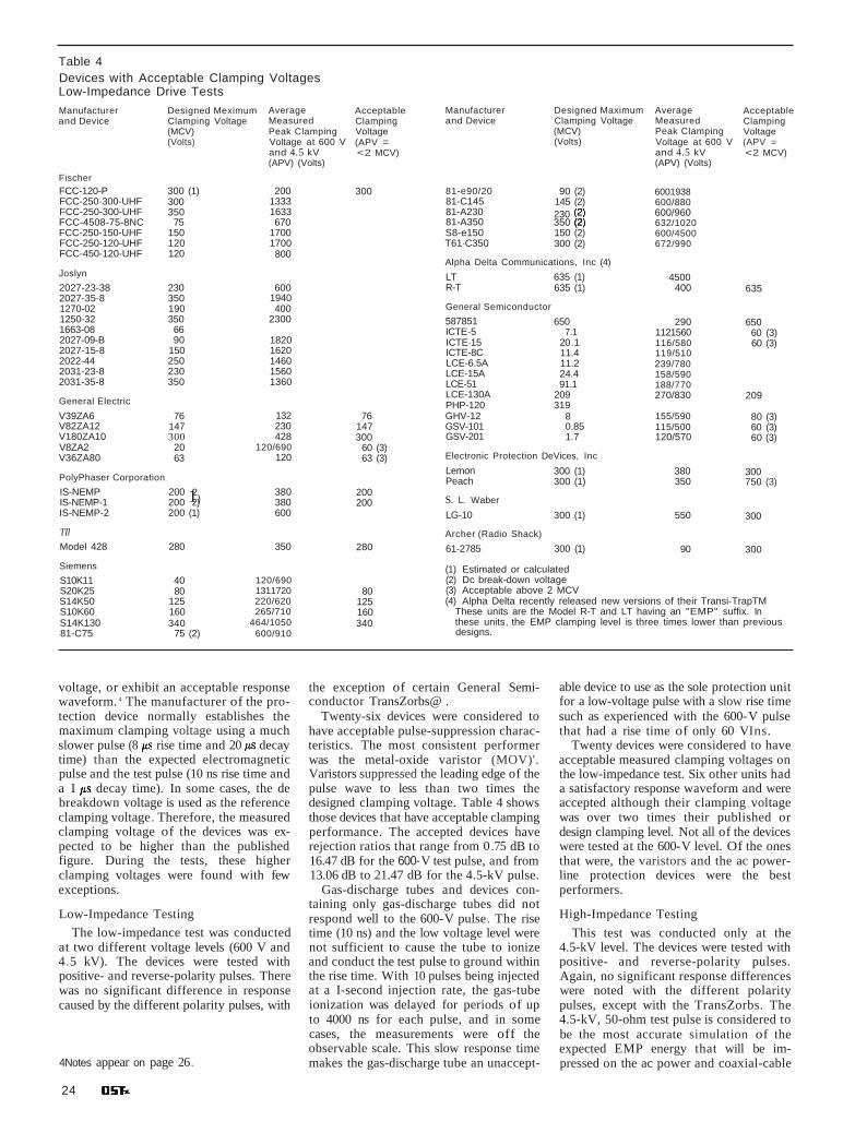
Table 4Devices with Acceptable Clamping VoltagesLow-Impedance Drive Tests
Manufacturerand Device
Designed MeximumClamping Voltage(MCV)(Volts)
AverageMeasuredPeak ClampingVoltage at 600 Vand 4.5 kV(APV) (Volts)
AcceptableClampingVoltage(APV =<2 MCV)
Manufacturerand Device
Designed MaximumClamping Voltage(MCV)(Volts)
AverageMeasuredPeak ClampingVoltage at 600 Vand 4.5 kV(APV) (Volts)
AcceptableClampingVoltage(APV =<2 MCV)
FischerFCC-120-P 300 (1) 200FCC-250-300-UHF 300 1333FCC-250-300-UHF 350 1633FCC-4508-75-8NC 75 670FCC-250-150-UHF 150 1700FCC-250-120-UHF 120 1700FCC-450-120-UHF 120 800
Joslyn
2027-23-38 230 6002027-35-8 350 19401270-02 190 4001250-32 350 23001663-08 662027-09-B 90 18202027-15-8 150 16202022-44 250 14602031-23-8 230 15602031-35-8 350 1360
General Electric
V39ZA6 76 132V82ZA12 147 230V180ZA10 300 428V8ZA2 20 120/690V36ZA80 63 120
PolyPhaser Corporation
IS-NEMP 200 12)380
IS-NEMP-1 200 2) 380IS-NEMP-2 200 (1) 600
TIl
Model 428 280 350
Siemens
S10K11 40 120/690S20K25 80 1311720S14K50 125 220/620S10K60 160 265/710S14K130 340 464/105081-C75 75 (2) 600/910
300
76147300
60 (3)63 (3)
200200
280
80125160340
81-e90/20 90 (2) 600193881-C145 145 (2) 600/88081-A230 230 600/96081-A350 350 (2 632/1020S8-e150 150 (2) 600/4500T61·C350 300 (2) 672/990
Alpha Delta Communications, Inc (4)
LT 635 (1) 4500R-T 635 (1) 400 635
General Semiconductor
587851 650 290 650ICTE-5 7.1 1121560 60 (3)ICTE·15 20.1 116/580 60 (3)ICTE-8C 11.4 119/510LCE-6.5A 11.2 239/780LCE-15A 24.4 158/590LCE-51 91.1 188/770LCE-130A 209 270/830 209PHP-120 319GHV-12 8 155/590 80 (3)GSV-101 0.85 115/500 60 (3)GSV-201 1.7 120/570 60 (3)
Electronic Protection DeVices, Inc
Lemon 300 (1) 380 300Peach 300 (1) 350 750 (3)
S. L. Waber
LG-10 300 (1) 550 300
Archer (Radio Shack)
61-2785 300 (1) 90 300
(1) Estimated or calculated(2) Dc break-down voltage(3) Acceptable above 2 MCV(4) Alpha Delta recently released new versions of their Transi-TrapTM
These units are the Model R-T and LT having an "EMP" suffix. Inthese units, the EMP clamping level is three times lower than previousdesigns.
voltage, or exhibit an acceptable responsewaveform. 4 The manufacturer of the protection device normally establishes themaximum clamping voltage using a muchslower pulse (8 rise time and 20 decaytime) than the expected electromagneticpulse and the test pulse (10 ns rise time anda I decay time). In some cases, the debreakdown voltage is used as the referenceclamping voltage. Therefore, the measuredclamping voltage of the devices was expected to be higher than the publishedfigure. During the tests, these higherclamping voltages were found with fewexceptions.
Low-Impedance Testing
The low-impedance test was conductedat two different voltage levels (600 V and4.5 kV). The devices were tested withpositive- and reverse-polarity pulses. Therewas no significant difference in responsecaused by the different polarity pulses, with
4Notes appear on page 26.
24
the exception of certain General Semiconductor TransZorbs@ .
Twenty-six devices were considered tohave acceptable pulse-suppression characteristics. The most consistent performerwas the metal-oxide varistor (MOV)'.Varistors suppressed the leading edge of thepulse wave to less than two times thedesigned clamping voltage. Table 4 showsthose devices that have acceptable clampingperformance. The accepted devices haverejection ratios that range from 0.75 dB to16.47 dB for the 600-V test pulse, and from13.06 dB to 21.47 dB for the 4.5-kV pulse.
Gas-discharge tubes and devices containing only gas-discharge tubes did notrespond well to the 600-V pulse. The risetime (10 ns) and the low voltage level werenot sufficient to cause the tube to ionizeand conduct the test pulse to ground withinthe rise time. With 10 pulses being injectedat a I-second injection rate, the gas-tubeionization was delayed for periods of upto 4000 ns for each pulse, and in somecases, the measurements were off theobservable scale. This slow response timemakes the gas-discharge tube an unaccept-
able device to use as the sole protection unitfor a low-voltage pulse with a slow rise timesuch as experienced with the 600-V pulsethat had a rise time of only 60 VIns.
Twenty devices were considered to haveacceptable measured clamping voltages onthe low-impedance test. Six other units hada satisfactory response waveform and wereaccepted although their clamping voltagewas over two times their published ordesign clamping level. Not all of the deviceswere tested at the 600-V level. Of the onesthat were, the varistors and the ac powerline protection devices were the bestperformers.
High-Impedance Testing
This test was conducted only at the4.5-kV level. The devices were tested withpositive- and reverse-polarity pulses.Again, no significant response differenceswere noted with the different polaritypulses, except with the TransZorbs. The4.5-kV, 50-ohm test pulse is considered tobe the most accurate simulation of theexpected EMP energy that will be impressed on the ac power and coaxial-cable

Table 5Devices With Acceptable Clamping VoltagesHigh-Impedance Drive TestManufacturer Designed Maximum Average Acceptable Manufacturer Designed Maximum Average Acceptableand Device Clamping Voltage Measured Clamping and Device Clamping Voltage Measured Clamping
(MCV) Peak Clamping Voltage (MCV) Peak Clamping Voltage(Volts) Voltage at (APV = (Volts) Voltage at (APV =
4.5 kV 50 Ohms <2 MCV) 4.5 kV 50 Ohms < 2 MCV)(APV) (Volts) (APV) (Volts)
FischerFCC-120-P 300 (1) 420 300 B1-G90/2O 90 (2) 210FCC-250-300-UHF 300 393 300 B1-G145 145 (2) 200 145FCC-250-300-UHF 350 260 350 B1-A23O 230 (2) 218 230FCC-450B-75-BNC 75 210 B1-A350 350 (2) 230 350FCC-25o-15O-UHF 150 220 150 S8-G150 150 (2)FCC-250-120-UHF 120 240 120 T61-C350 300 (2) 250 300FCC-45o-12O-UHF 120 120 120
Alpha Delta Communications, Inc (4)Joslyn LT 635 (1) 700 6352027-23-3B 230 310 230 RT 635 (1) 720 6352027-35-B 350 366 3501270-02 190 600 500 (3) General semiconductor1250-32 350 940 587851 650 600 6501663-08 66 90 66 ICTE-5 7.1 1342027-09-B 90 · 378 ICTE-15 20.1 1462027-15-B 150 242 150 ICTE-8C 11.4 1242022-44 250 294 250 LCE-6.5A 11 .2 2502031-23-B 230 336 230 LCE-15A 24.4 2002031-35-B 350 291 350 LCE-51 91.1 220
General ElectricLCE-13OA 209 210 209PHP-120 319 400 319
V39ZA6 76 254 150 (3) GHV-12 8 218V82ZA12 147 254 147 GSV-101 0.85 168V180ZA10 300 388 300 GSV-201 1.7 174V8ZA2 20 174 100 (3)V36ZA80 63 170 100 (3) Electronic Protection Devices, Inc
PolyPhaser CorporationLemon 300 (1) 580 300Peach 300 (1) 1000 750 (3)
IS-NEMP 200 (2) 140 200IS-NEMP-1 200 (2) 150 200 S. L WeberIS-NEMP-2 200 (1) 160 200 LG-10 300 (1) 600 300
TIl Archer (Radio Shack)Model 428 280 410 280 61-2785 300 (1) 300 300
Siemens (1) Estimated or calculatedS10K11 40 186 100 (3) (2) Dc break-down voltageS20K25 80 190 150 (3) (3) Accaptable above 2 MCVS14K50 125 234 125 (4) Alpha recently released a new version of their Transi-TrapTM. ThisS10K60 160 232 160 unit has an EMP suffix. In these units, the EMP clamping level is threeS14K13O 340 436 340 times lower than previous designs.81-G75 75 (2) 220
interfaces to the amateur's equipment.Therefore, the results of this test wereexpected to be the most significant of theprogram. The devices tested are listed inTable 5.
Varistors
Varistors performed adequately duringthe test. The General Semiconductor,General Electric and Siemens varistorsperformed consistently. The varistors testedhad clamping voltages ranging from 0.85 Vto 350 Y. The average measured varistorclamping voltage ranged from a low of 168Y to a high of 436 Y. Nine out of 12 varistors were found to have acceptable clamping voltages. Three varistors exceeded theirdesigned clamping voltage, but performedconsistently and could be used at a highervoltage level if desired.
Gas-Discharge Tubes
The advantage of using a gas-dischargetube is in its ability to handle large powertransients for short periods.' One of thedisadvantages of gas tubes is that once theybegin to conduct, a continuous ac or de
operating voltage of the proper level willkeep the tube in the conductive state afterthe pulse has passed. This characteristic canresult in the destruction of the tube, as wasexperienced during another phase of thistest program. Several gas tubes were destroyed when attached to an isolated acpower source and then exposed to a 25-kYpulse. The pulse started the tube's conduction and the ac power sustained the tube'sionization and conduction until the tubewas destroyed.
In a special test, two gas tubes were connected in series between the pulse sourceand system ground. An ac voltage was impressed across the source circuit and thenthrough a lOO-ohm resistor to ground. Thegas tubes did not begin to conduct untilthey were puls~d . When pulsed, the tubesionized and conducted the pulse to ground,then shut off. The applied ac power did notsustain the ionization across the seriesconnected tubes.
Similarly, a gas tube and a varistor wereconnected in parallel to ground with an accurrent in the circuit. When pulsed, thetube ionized and conducted the transient
current to ground while sharing the currentwith the varistor, then shut down withoutbeing destroyed. It was concluded that gastubes could be used for their high powerhandling capabilities, but only when usedat the proper voltage levels or with anotherdevice to cut off the tube. This design adaptation is found in commercial ac-powerprotection devices and RF devices using gastubes.
Coaxial-Line Protectors
Eleven RF protection devices from threesuppliers were tested. These devices aredesigned to be placed in the coaxial transmission line. All of the units, with the exception of the one with the lowest clampingvoltage, were accepted. This exception, theFischer FCC-450B-75-BNC, is rated toclamp at 75 volts. It did suppress the 4.5-kYpulse to an average of 210 Y and was givena rejection ratio of 26.62 dB, still very goodperformance.
The measured clamping voltages rangedfrom a low of 120 Y (for a device rated at120 Y) to a high of 720 Y (for a unit ratedat 635 V). The coaxial-line protectors ex-
September 1986 25

hibited a very high rejection ratio to the4.5-kV high-impedance pulse, starting at alow of 16.15 dB for the Alpha Delta TransiTrap R-T to a high of 30.14 dB for thePolyphaser IS-NEMP devices. The Fischer FCC-250-350-UHF clamped 90 V belowits rated clamping voltage of 350 V. Thiswas not considered to be a problem, buta lower clamping voltage potentially couldinterfere with the transmitted RF signal.
Power-Line Protectors
There are numerous ac power-line protection devices available, but our selectionwas limited to the lowest-cost devices. Tendevices from seven sources were tested. Allof the units, with the exception of theFischer FCC 120 F-P, Joslyn model1250-32 and the General Semiconductormodels 587B051 and PHP 120, could beplugged directly into an ac wall outlet.
Internally, the devices consist of a combination of gas-discharge tubes, varistorsor other protective circuitry. All except onewere found to be acceptable. The publishedclamping voltages ranged from a low of190 V to a high of 650 V. For severaldevices, the designed clamping voltage wasnot known, so a 3OO-V level was assignedto them for purposes of comparison. Themeasured clamping voltages ranged froma low of 300 V to a high of I kV .
TransZorbs
Seven units from General Semiconduc-
tor were checked in an effort to find adevice that would clamp at a very low voltage level. The one with the lowest-ratedclamping voltage is the lCTE-5 (7.1 V); theunit with the highest-rated clamping voltage is the LCE-130A (209 V). Averagemeasured clamping voltages ranged froma low of 124 V to a high of 250 V. Onlyone of the units ' was accepted - theLCE-130A. Rated at 209 V, it had an average clamping voltage of 210 V. All of theother TransZorbs conducted only at levelsconsiderably above their ratings.
Test to Failure
The larger of the two pulse generatorswas used to generate a 25-kV pulse at 4 kAfor I This provided a total energy output of 100 J. Up to five each of the 36devices were tested with only three of themapproaching failure. The three ac powerline protection devices experienced excessive internal arcing, although they did notfail completely. All of the other devices survived the 10 pulses and suppressed the voltage transient voltage without failure.
Conclusions
Of the 56 devices tested, there are manythat have acceptable transient-voltage suppression capabilities and can be used forthe protection of Amateur Radio equipment. These include ready-made units fordirect connection to the ac power lines andcoaxial antenna lines as well as smaller
devices that can be used alone (varistors)or in combinations (gas-dischargetube/ varistor) to protect other points.[Editor's Note: This series of articles is condensedfrom the National Communications System report(NCS TIB 85-10) Electromagnetic PulsefTransientThreat Testing of Protection Devices forAmateur/Military Affiliate Radio System Equipment.A copy of the unabridged report is available fromthe NCS. Write (no SASE required) to Mr DennisBodson, Acting Assistant Manager, Office ofTechnology and Standards, National Communi·cations System, Washington, DC 20305·2010, orcall 202-692-2124 between the hours of 8:30 AMand 5 PM Eastern.]
Notes
'The published clamping voltage of a device isthe average voltage level where the devicewill change from a nonconducting state to aconducting state.
5Varistors are voltage-dependent devices thatbehave in a nonlinear electrical mannersimilar to back-to-back Zener diodes. Whensubjected to high-voltage transients, the varistor's impedance changes over a large rangefrom a near open circuit to a highly conductive circuit, thereby switching the transientvoltage to ground or some other point.Varistors are designed for a large assortmentof switching (clamping) voltages.
6The tubes tested are sealed gas-dischargetubes consisting of two or three electrodesproperly separated by insulators and filledwith a rare gas. These tubes are designed toswitch rapidly at a specific voltage level from anonconductive to a conductive state (arc mode)when subjected to a fast-rising voltagetransient. When the voltage across the tube'selectrodes is increased, ionization of the inertgas occurs and the tube conducts across theelectrode gap. The breakdown-voltage level isdetermined by the design of the tube's electrode spacing and the gas pressure. QST i

Electromagnetic Pulse and theRadio AmateurPart 3: In Part 2, we told how the EMP transient-protectiondevices were tested individually under isolated conditions. Now,the protectors are connected to Amateur Radioequipment and retested. t
By Dennis Boelson, W4PWFActing Assistant Manager,Technology and StandardsNational Communications SystemWashington, DC 20305-2010
..Table 6Commercial Protection Devices Tested
Table 7Homemade Transient Protection Devices TestedDevice Name Description
SIOV ac test box Three Siemens MOVs (S14K130) installed in an ac receptaclebox. One MOV wired from hot to ground, one from neutral toground and one between hot and neutral
GE MOV One GE MOV (V36ZA80) installed across the 12-V dc power linebetween hot and ground.
SIOV RF test box The Siemens MOV (S14K130) installed in a metal box. The boxhad UHF connectors attached to both ends and a wireconnected between the center conductors of the twoconnectors. The MOV was connected to the wire on one sideand to the box on the other side.
Siemens UHF test box Two Siemens gas-gap tubes (BI-A350) installed in the UHFconnector box described above. The tubes were wired inseries from the center conductor to the side of the box.
Joslyn UHF test box Two Joslyn gas-gap tubes (2031-35B) installed in the UHFconnector box in series from the center conductor to ground.
UHF coaxial T Two Siemens gas-gap tubes (BI-A350) installed in series betweenthe center conductor and case, on one leg of a coaxialT connector.
Description
Coaxial line suppressorCoaxial line suppressorCoaxial line suppressorCoaxial line suppressorCoaxial line suppressorMiniature gas-tube surge protector (MSP)Metal oxide varistor (GE-MOV)Coaxial line protectorCoaxial line protectorCoaxial line protectorPlug-in power line protectorMetal oxide varistor (SIOV)Button type surge voltage protectorCoaxial line protectorThree-outlet ac power strip/protector
Part Number
FCC-250-300-UHFFCC-250-350-UHFFCC-250-150-UHFFCC-250-120-UHFFCC-450-120-UHF2031-35-BV36ZA80IS-NEMPIS-NEMP-1IS-NEMP-2Model 428S14K130B1-A350Transi-Trap R-T61-2785
Manufacturer
FischerFischerFischerFischerFischerJoslynGeneral ElectricPolyphaser CorpPolyphaser CorpPolyphaser CorpTilSiemensSiemensAlpha DeltaArcher
tParts 1 and 2 appear in the Aug and Sep issuesof OST, respectively. Part 4 will appear in asubsequent issue.
The tests described in the previousinstallment subjected 56 selectedprotection devices to several differ
ent injection pulses that simulated thewaveforms and energies associated withEMP and lightning discharges. Those protective devices found acceptable during thefirst test program were then connected toseveral types of radio equipment and tested for their effectiveness in a typicalAmateur Radio installation.
Since t here is a large number of possiblecombinations of protection devices andradio equipment, low-cost devices wereevaluated first. If they were found unacceptable, higher-cost protection deviceswere installed and tested until an acceptable prolection scheme was developed.After completing the testing of the low-costcommercial devices (see Table 6), severalhomemade units, assembled from previously tested components (see Table 7),were checked. This was done with an eyetoward finding a very low-cost protectiondevice that could be built by the radioamateur. Six of these units will be describedin the next installment of this series.
Sixteen system configuration s (seeTable 8) were tested at frequencies from 1.8to 435 MHz. These systems included bothnew and old gear (some no longer manufactured, but available on the used-equipmentmarket), and lube-type and transistorizedradios. The equipment tested was manufactured by Drake, ICOM, Kenwood, Swanand Yaesu.
Measurements were taken of the radiosystem's performance before and after eachpulse or pulse series to compare the radio's
38 Q S T

Test Equipment
A parallel-plate EMP simulator 24 feetlong, 20 feet wide and I I feet high (Fig 11)was used. The Marx generator was chargedby a high-power dc power supply and discharged through a spark-gap bank and output capacitor into the simulator's wireelements. These wire elements extendedfrom the Marx generator through aI6-foot-Iong transitional section to a bankof copper-sulfate load resistors, whichprovided a termination load resistance(110-130 ohms) for the pulser. A 30-kVcharge to the Marx generator was sufficientto provide a 50-kV1m field strength witha pulse rise time near IOns inside theworking volume. The 30-kV charge to theMarx generator produced a 240-kV chargeon the pulser elements.
A round and a square H-field sensorwere used to provide daily calibration ofthe simulator and to measure the fieldstrength during each test. Normally, onlyone sensor was used during the actual test.Four current sensors measured the outputof Amateur Radio antennas erected in the
Antenna Transient Injection
A larger L-shaped antenna wasconstructed within the test chamber forevaluation as an injection pulse generatorfor the antenna port of the equipmentunder test. Current, measured through a50-ohm load resistor, was limited to about80 A when two short lengths of coaxialcable were used between the antenna andload. Results of the removal of the cablefrom the transient path led to theconclusion that the coaxial cable andconnectors greatly limit the magnitude ofthe transient imposed on radio equipment.The L antenna used in this test was considered adequate to stress any antenna connection terminal (at the equipment end)with a pulse as large as the coaxial cablecould transmit. A possibility exists in a realtransient situation that the coaxial cable itself may be damaged if not protected at theantenna end, but this condition could notbe tested by the configuration used here.
grounded to the pulser ground plane at asingle supply box within the transient field.A transient injection pulse was generatedby an L-shaped wire antenna within the testchamber. The antenna was connected tothe hot lead of a power plug inserted closeto the protective device under test. Whena commercial plug-in device was used, thetransient was injected into the same receptacle into which the device was plugged. Ifa fabricated protection device was used, thetransient was injected into the device receptacle alongside the equipment power plug.This maximized the stress on the equipmentwhile offering an opportunity for the freefield transient to couple with the equipmentpower cord after the protection device. Thedimensions of the L-shaped antenna wereadjusted until a current of 130 A wasproduced in a 50-ohm load.
System 13Kenwood TR-2600 2-m hand-held
transceiver
System 14
Drake T-4XC HF transceiverR-4C HF receiver48 power supply
System 15 (Not tested)Collins KWM-2A HF transceiver
KWM-2A power supply
System 16
Swan 250 HF transceiver117Z power supply
AntennasMosley JRS TA33 3-element tribanderCushcraft AV-5 80- to 10-m vertical
Other ItemsAstron VS-35 power supplyHonda EG 650 generator
and two L-shaped wires were attached tothe equipment.
Transient Injection Methods
The working volume of the parallel-platesimulator used for these tests, while large,was not sufficient to house an entire radiostation including an antenna and residentialpower-line drop. Therefore, the stationequipment was placed in the chamber, andpulses were injected that simulated thestresses carried to the equipment by thepower lines and antenna. The maximumtransient expected from the power line wasabout 6 kV since household wiring shouldlimit the transient to this level. Antennaconnections, however, are limited only bythe spark-over levels of the installedantenna cabling.
Power-Source Transient Injection
Power for the systems in the testchamber was provided by an isolated generator that would prevent interaction withthe pulser and data links used in the experiment. To simulate the connection of a typical residential supply, the neutral andground leads of the isolated system were
System 4ICOM IC-745 HF Transceiver
IC-PS35 internal power supplyIC-SM6 desk microphoneIC-AT100 antenna matching networkIC-SP3 external speaker
System 5ICOM IC-745 HF transceiver
IC-PS35 internal power supply
System 6ICOM IC-27A 2-m mobile transceiver
System 7tCOM IC-02AT 2-m hand-held transceiver
System 8ICOM IC-271 A 2-m transceiver
System 9ICOM IC-471A 430- to 450-MHz transceiver
System 10Kenwood T8-430S HF transceiver
PS-430 power supplyMC-SO desk microphoneAT-250 antenna matching networkST-430 ex1ernal speaker
System 3Yaesu FT-726 VHF/UHF all-mode
transceiver
Table 8Amateur Radio System Configurations and Ancillary Equipment Tested
System 1 System 11Yaesu FP-757HF power supply Kenwood T8-430S HF transceiver
FT-757GX all-mode transceiver PS-430 power supplyFC-757AT antenna matching network MC-80 microphone
System 2 System 12Yaesu FP-757HF Kenwood TR-7930 2-m mobile transceiver
FT-757GX
transmitter power output and receiversensitivity. First, stand-alone (equipmentunwired) radio systems were subjected toa field-pulse wave. This disclosed anyinherent design weaknesses and identifiedthe internal areas that required protection.Damaged equipment was repaired andreturned for further testing. After a seriesof field-only pulse tests, the simultaneousfield and injection pulse tests were made.
Test Program
Threat Definition
The peak values used in these tests were:
EMP simulator pulse field: 50 kV1mRF drive pulse: 275 A, 13.75 kVAc drive pulse: t30 A, 6.5 kV
In the Simulator Field Tests, the radiosystem was placed in the working volumeof a large parallel-plate EMP simulator.The simulator's Marx pulse generator wasdischarged into the pulser wire elementswith sufficient energy to produce a50 kV1m field strength with a lO-nanosecond pulse rise time. For the Simultaneous Field and Injection Pulse Tests, theradios were kept in the same environment
October 1986 39

--- --- - - - - - --- -------------,
16' 24'
WIREELEMENTS
'
TERMINATOR
Fig ll-A drawing of the large parallel-plate EMP simulator used in the tests. The Marx generator is a high-voltage pulse generator inwhich several capacitors are charged in parallel through a high-resistance network. When the charge reaches a critical value, dischargeoccurs through spark gaps.
pulser field . The sensors also measured the.output of the L-shaped wire antennas thatwere used to drive the ac power lines andantenna coaxial cables. A shielded coaxialprobe and a fiber-optic system with abattery-powered, shielded transmitter tookH- and E-field measurements. Sensormeasurements were recorded on anoscilloscope. Photographs of theoscilloscope display were taken for eachsimulator pulse . Other test equipment included four signal generators and awattmeter.
Radio System Tests
Each radio system was checked beforeand after each pulse. Transmitter poweroutput was measured in the CW mode.This was done with and without anytransient-protection devices in the feed line.That provided an evaluation of the protection device's suitability for thatparticular radio system, by showing itsability to pass the transmitted signalwithout clamping or without contributinga substantial loss of power output. Voicemodulation was checked by observing thedeflection of the wattmeter needle whilespeaking into the microphone. In sometests, the transmitter was monitored on asimilar radio.
Receivers were placed on a set frequencyin the USB mode with the RF amplifier on(if selectable) and the RF gain control setto maximum. The output of a signalgenerator was increased until the receiver'sS meter read S5. (Receivers without an Smeter were measured by listening for anaudible signal in the speaker.)
Series A
For these tests, the radio equipment wasplaced on wooden carts 34 inches above thesimulator floor. No interconnecting wireswere attached to the equipment. All permanently attached external wires (such aspower cords) were coiled and placed underthe case of the radio equipment. This testevaluated the susceptibility of the radio'sinternal wiring and components to selfgenerated transient pulses resulting from
40 QST
exposure to a field pulse. All radios (withthe exception of one, System 15, that wasdropped from the test for prolonged maintenance problems) passed these tests withno measurable degradation.
Series B
Again, the radios were placed on thewooden carts. They were unpowered andungrounded, but this time the interconnecting wiring and power cords were inplace. This second test was designed toevaluate the radio's susceptibility totransient pulses generated by the internalwiring, and any external wires includingmicrophone and power cords. All radiospassed this test except for two, Systems 3and 8. The receivers in these two systemsexhibited decreased sensitivity: that ofSystem 3 by 26 dBm and 8 dBm for System8. Since a strong signal was still audible,the two systems were considered not to beseriously degraded and were accepted forfurther testing .
Series C
Only System 2 was used for this test. Thetransceiver was placed on the pulser floor ·and grounded to the pulser ground plane.All wiring was attached except for thecoaxial feed line to the antenna . Tests wereperformed first with no ac power applied,then with power on. No degradation of thetransceiver performance was measured .
Series D
This was a power-on test of theequipment with all external wiring andperipherals in place, including the coaxialantenna cable. Commercial transient-protection devices were installed in the acpower and antenna feed lines. Then, the acpower line and coaxial antenna cable weredriven by an injected signal at the threatlevels described earlier. All the devices, except one, provided adequate protection.System 2 sustained some internal damageduring a test when the Alpha Delta R-TTransi-Trap was in the circuit. The TransiTrap devices had performed satisfactorilyduring the first test program. [Note: As a
result of this report, Alpha Delta has a new"EMP series" R-T and LT design . The newversion has a clamping level three timeslower than previous designs for maximumsafety-Ed.]
Another protective device failed a posttest check. The Fischer FCC 450-120-UHFwould not pass RF signal power. It wasreplaced.
Series E
Now, five assembled (experimental)transient-protection devices were tested (seeTable 7). Of these five, one was an ac-Iineunit and four were RF assemblies. Thesetests were designed to find a low-costsolution to the transient-protection requirements of the radio systems under test. Allof the units provided ad~uate protectionof the radio equipment during the testpulse. Further testing revealed that three ofthe devices blocked the transmitted signal.The Siemens Metal Oxide Varistor (SlOV)RF Test Box containing a large-capacitancevaristor blocked the signal over a wide frequency range . The Siemens UHF Test Boxand Joslyn UHF Test Box containing thegas gaps were adequate at HF, but blockedthe signal at higher frequency ranges.Although these three devices are adequatefor receiver use, they are not recommendedfor use with a transmitter.
The UHF coaxial T was the bestassembled device; it provided transientprotection and could pass the transmittedsignal over the full range of test frequencies. Also, the SIOV AC Test Box repeatedly provided necessary power protectionrequired by the radio equipment. These twodevices will be discussed in more detail inthe next installment.
Series F
This series of field and injection tests hadthree configurations. First, the radiosystems were fully protected. Then, transient protection was removed from thecoaxial feed line. Finally, protection wasremoved from the ac power line as well . Asexpected , some equipment damage wasexperienced. However, the most surprising

result of this test series was that only oneradio system (System 2) experienced significant, permanent performance degradation.The other radios suffered various amountsof lowered transmitter power output andreceiver sensitivity, but were still operational in their damaged state. A contributingfactor in the survivability of the equipmentwas the influence the RG-8 coaxial cablehad on the RF injection pulse (discussedlater).
Antenna Tests
Measurements were taken of theresponse of two amateur antennas to thesimulator pulse field in several differentconfigurations. These included measurements taken with a 75-foot length of RG/8cable attached and with a connection to thepulser ground plane directly through a50-ohm resistor. The Mosley JRS TA33 J rantenna generated a maximum of 152 Athrough 50 ohms for a 7.6 kV pulse level.The Cushcraft AV-5 produced a maximumoutput of 170 A through the 50-ohmresistor for an 8.67 kV pulse level.
An L-shaped wire antenna was placed inthe pulser field to generate a drive currentthat could be injected into the coaxial cableattached to the radio equipment under test.The maximum measured output of thisantenna was 175 A through a 50-ohm resistor for a maximum pulse level of 13.75 kV.
Two "rubber ducks" were tested. Themaximum measured current was 8 Aproducing 400 V through 50 ohms. Thislow current was not sufficient to cause anydegradation of the hand-held transceivers.
Coaxial Cable Effects
Measurements were made to determinethe response of RG/8 coaxial cable in thepulse field alone and when attached to threedifferent antennas: two amateur antennasand the RF-drive antenna. At the antenna
side of the cable, large currents (250290 A) could be found, but at the oppositeend-with the 50-ohm resistor connectedto ground-only 50-110 A was measured.We suspected that the coaxial cable wasarcing. To test this, a piece of RG/8 cablewas connected to a high-voltage dc supplyand the supply voltage was slowlyincreased. Arcing between the centerconductor and the coaxial connector beganat a potential of 4 kV; the cable beganarcing internally at 5.5 kV. We concludedthat the RG/8 cable was acting as a sparkgap protector for the equipment under test.Given this condition, the protection devicesinstalled in the feed line were needed onlyto suppress the approximate 4.4-kV pulsethat would get through the cable.
Observations
Most of the solid-state, and all of thetube-type, radios were not susceptible to thesimulator field pulses until long, externalwires were attached. Short wiresmicrophone, power cord and internalwiring-did not generate sufficienttransient pulse energy to produceobservable damage to the radio equipment.When power lines and antennas areattached to radio equipment, however, protection must be provided. With longexternal wires attached and no protectionprovided, a single pulse could cause disruption of the microprocessor-controlleddisplays, cause frequency shifts andpermanently damage the radio's internalcomponents, Two notable exceptions arethe handheld and mobile radios. Evenwith antennas attached, no equipmentdegradation was noted.
Other equipment used by the radioamateur can be damaged by transientpulses. A line-operated dc power supply(Astron VS-35) failed when pulsed with an
unprotected power source. A hand-heldtransceiver's (lCOM lC-02AT) display waspermanently damaged when the radio wasplugged into its battery charger and theninto an unprotected ac power source. Thebattery charger was also damaged. AHonda portable power generator was fullystressed with field and injection pulses andwas unharmed. System I sustained damageto its antenna matching network, but theattached transceiver was unhurt. (In thiscase, the matching network may have protected the transceiver.) When System 4 waspulsed in an unprotected configuration, itsmatching network did not provide adequateprotection for the transceiver; thetransceiver's frequency display wastemporarily disrupted.
Conclusions
Most Amateur Radio equipment shouldbe protected from Iightnirig and EMP toprevent damage that can degrade theequipment's performance. Adequatetransient-pulse protection for most radiosystems can be obtained by adding theproper protection devices to the ac powerlines and the transmission line. Batterychargers for hand-held transceivers andline-operated dc power supplies should alsobe protected. With a minimum amount ofprotection, radio systems should survivetransient pulses produced by lightningstrikes and EMP. A direct lightning stri keis another matter.
[Editor's Note: This series of articles is condensedlrom the National Communications System report(NCS TIB 85-10) Electromagnetic PulselTransientThreat Testing of Protection Devices for Amateur/Military Affiliate Radio System Equipment. A copyof the unabridged report is available from theNCS. Write (no SASE required) to Mr DennisBodson, Acting Assistant Manager, Office ofTechnology and Standards, National Communications System, Washington. DC 20305-2010, orcall 202-692-2124 between the hours of 8:30 AMand 5 PM Eastern.] . Q S T

Electromagnetic Pulse and theRadio AmateurPart 4: What can be done to protect an Amateur Radio stationfrom lightning and EMP transients? Here are some ideas onprocedures and protective devices.tBy Dennis Bodson, W4PWF
Acting Assistant ManagerOffice of Technology and StandardsNational Communications SystemWashington, DC 20305-2010
The equipment test programdescribed in the preceding threearticles demonstrates that most
Amateur Radio installations can be protected from lightning and EMP transients
tparts 1-3 appear in Aug, Sep and Oct 1986OST.
with a basic protection scheme. Most of theequipment is not susceptible to damagewhen all external cabling is removed . Youcan duplicate this stand-alone configuration simply by unplugging the ac powercord from the outlet, disconnecting theantenna feed line at the rear of the radioand isolating the radio gear from any other
\1/ ANTENNA
long metal conductors . Or, you can addtwo transient-protection devices to theinterconnected system; that will also closelyduplicate the stand-alone configuration.
The ac power line and antenna feed lineare the two important points that shouldbe outfitted with transient protection. Thisis the minimum basic protection scheme
LEGEND:
P1-P2-PlUG-1N AC POWERTRANSIENT SUPPRESSOR
Cl -C2-COAX,lAL LINE RF TRANSIENTSUPPRESSOR
Rl ·A2-VAAISTQR BOXES ANDCONTROL CABLE CAN BESHIELDED
AN TENNAROTATOR
1ROTATORCONTROL
CABLE
COAX {RG - 81
GROUND PANEL (BUS BARINO. 2 GAU GE SOLID WI RE OR SOLID STRAP j
GROUND GROUND GROUND GROUND GROUND
- o0= 0HAM
SHACK o0GROUND0 COAX
(SY STEM AC POWER (RG-8)GROUNDI
ACPOWER
AUDIO CABLE COAX
[ [
o 0o
o 0o
ACPOWER
ROTATORCONTROL
CABLE
SPEAKER POWERSUPPLY
TRANSCEIVER
13 .8 V DC J
ANTENNAMATCHINGNETWORK
ROTATOR REMOTE
CONTROL UNIT
ANTENNA MATCH INGNETWORK CONTROL CABLE
MICROPHONE
Fig 12-Transient suppression techniques applied to an Amateur Radio station.
30

TELEPHONE COGROUND
RADIOEQUIPMENT
AC POWERGROUND
-TOWER
SYSTEMGROUND
(A)
GND
(8)
TRANSIENTSUPPRESSORS
-----
TELEPHONEGROUND
BURIED GROUND WIRE
SYSTEMGROUND
COAXIAL CABLE
SOLID WIRENO.6 GAUGE /
ORBURIED I" DEEP /
//
/I
GROUND PANEL
TRANSIENT PATH TO GROUND
ANTENNAGROUND
Fig 13-At A, the proper method of tying all ground points together. The transient path toground with a single-point ground system and use of transient suppressors is shown at B.
General Considerations
Because of the unpredictable energycontent of a nearby lightning strike or otherlarge transient, it is possible for a metaloxide varistor (MOY) to be subjected to anenergy surge in excess of its ratedcapabilities. This may result in thedestruction of the MOY and explosiverupture of the package. These fragmentscan cause damage to nearby componentsor operators and possibly ignite flammablematerial. Therefore, the MOY should bephysically shielded .
A proper ground system is a key factorin achieving protection from lightning andEMP transients . A low-impedance groundsystem should be installed to eliminatetransient paths through radio equipmentand to provide a good physical ground forthe transient-suppression devices. A singlepoint ground system is recommended (seeFig 13). Inside the station, single-pointgrounding can be had by installing aground panel or bus bar. All externalconductors going to the radio equipmentshould enter and exit the station throughthis panel. Install all transient-suppressiondevices directly on the panel. Use theshortest length(s) possible of no. 6 solidwire to connect the radio equipment case(s)to the ground bus.
recommended for all Amateur Radio installations. (For fixed installations, consideration should also be given to theantenna rotator connections-see Fig 12.)Hand-held radios equipped with a "rubberduck" require no protection at the antenna jack. If a larger antenna is used with thehand-held transceiver, however, a protection device should be installed.
Fixed Installations
Ac Power-Line Protection
Tests have indicated that householdelectrical wiring limits the maximumtransient current that it will pass to approximately 120 A. Therefore, the amateur'sstation should, if possible, be installedaway from the house ac entrance panel andbreaker box to take advantage of theselimiting effects.
Ac power-line protection can be provided with easy-to-install, plug-in transientprotectors. Ten such devices were tested(see Table 9). Six of these can be pluggeddirectly into an ac outlet. Four are modulardevices that require more extensiveinstallation and, in some cases, more thanone module.
The plug-in-strip units are the bestoverall choice for the typical amateurinstallation . They provide the protectionneeded, they're simple to install and can bemoved easily with the equipment to otheroperating locations . The modular devicesare second choices because they all requiresome installation, and none of the unitstested provided full EMP protection for allthree wires of the ac power system.
Table 9Ac Power-Line Protection Devices
MeasuredHigh-Z
Manufacturer Device Approximate ClampingCost Voltage(US Dollars) (Volts)
Modules
Fischer FCG-120F-P 55 420Joslyn 1250-32 31 940General
Semiconductor 587B051 56 600General
Semiconductor PHP 120 50 400
Plug-Ins
Joslyn 1270-02 49 600Til 428 45 410Electronic
ProtectionDevices Lemon 45 580
ElectronicProtectionDevices Peach 60 1000
S L Waber LG-10 13 600Archer 61-2785 22 300
November 1986 31
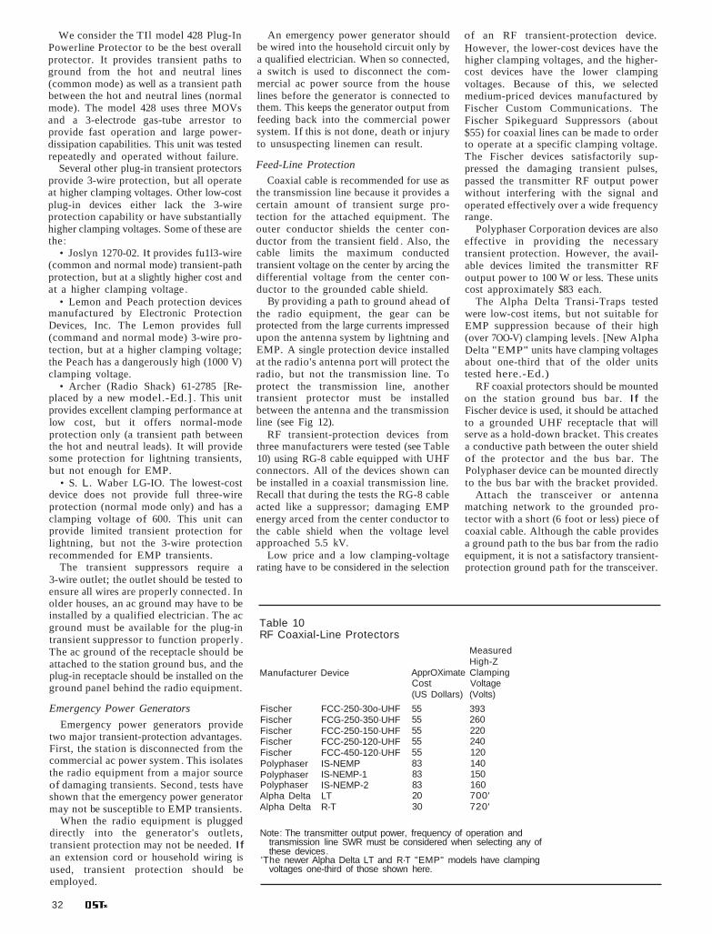
Note: The transmitter output power, frequency of operation andtransmission line SWR must be considered when selecting any ofthese devices.
'The newer Alpha Delta LT and R·T "EMP" models have clampingvoltages one-third of those shown here.
Table 10RF Coaxial-Line Protectors
An emergency power generator shouldbe wired into the household circuit only bya qualified electrician. When so connected,a switch is used to disconnect the commercial ac power source from the houselines before the generator is connected tothem. This keeps the generator output fromfeeding back into the commercial powersystem. If this is not done, death or injuryto unsuspecting linemen can result.
Feed-Line Protection
Coaxial cable is recommended for use asthe transmission line because it provides acertain amount of transient surge protection for the attached equipment. Theouter conductor shields the center conductor from the transient field . Also, thecable limits the maximum conductedtransient voltage on the center by arcing thedifferential voltage from the center conductor to the grounded cable shield.
By providing a path to ground ahead ofthe radio equipment, the gear can beprotected from the large currents impressedupon the antenna system by lightning andEMP. A single protection device installedat the radio's antenna port will protect theradio, but not the transmission line. Toprotect the transmission line, anothertransient protector must be installedbetween the antenna and the transmissionline (see Fig 12).
RF transient-protection devices fromthree manufacturers were tested (see Table10) using RG-8 cable equipped with UHFconnectors. All of the devices shown canbe installed in a coaxial transmission line.Recall that during the tests the RG-8 cableacted like a suppressor; damaging EMPenergy arced from the center conductor tothe cable shield when the voltage levelapproached 5.5 kV.
Low price and a low clamping-voltagerating have to be considered in the selection
of an RF transient-protection device.However, the lower-cost devices have thehigher clamping voltages, and the highercost devices have the lower clampingvoltages. Because of this, we selectedmedium-priced devices manufactured byFischer Custom Communications. TheFischer Spikeguard Suppressors (about$55) for coaxial lines can be made to orderto operate at a specific clamping voltage.The Fischer devices satisfactorily suppressed the damaging transient pulses,passed the transmitter RF output powerwithout interfering with the signal andoperated effectively over a wide frequencyrange.
Polyphaser Corporation devices are alsoeffective in providing the necessarytransient protection. However, the available devices limited the transmitter RFoutput power to 100 W or less. These unitscost approximately $83 each.
The Alpha Delta Transi-Traps testedwere low-cost items, but not suitable forEMP suppression because of their high(over 7OO-V) clamping levels . [New AlphaDelta "EMP" units have clamping voltagesabout one-third that of the older unitstested here.-Ed.)
RF coaxial protectors should be mountedon the station ground bus bar. If theFischer device is used, it should be attachedto a grounded UHF receptacle that willserve as a hold-down bracket. This createsa conductive path between the outer shieldof the protector and the bus bar. ThePolyphaser device can be mounted directlyto the bus bar with the bracket provided.
Attach the transceiver or antennamatching network to the grounded protector with a short (6 foot or less) piece ofcoaxial cable. Although the cable providesa ground path to the bus bar from the radioequipment, it is not a satisfactory transientprotection ground path for the transceiver.
MeasuredHigh-Z
ApprOXimate ClampingCost Voltage(US Dollars) (Volts)
55 39355 26055 22055 24055 12083 14083 15083 16020 700'30 720'
FCC-250-30o-UHFFCG-250-350·UHFFCC-250-150·UHFFCC-250-120-UHFFCC-450-120·UHFIS-NEMPIS-NEMP-1IS-NEMP-2LTR-T
FischerFischerFischerFischerFischerPolyphaserPolyphaserPolyphaserAlpha DeltaAlpha Delta
Manufacturer Device
We consider the TIl model 428 Plug-InPowerline Protector to be the best overallprotector. It provides transient paths toground from the hot and neutral lines(common mode) as well as a transient pathbetween the hot and neutral lines (normalmode). The model 428 uses three MOVsand a 3-electrode gas-tube arrestor toprovide fast operation and large powerdissipation capabilities. This unit was testedrepeatedly and operated without failure.
Several other plug-in transient protectorsprovide 3-wire protection, but all operateat higher clamping voltages. Other low-costplug-in devices either lack the 3-wireprotection capability or have substantiallyhigher clamping voltages. Some of these arethe:
• Joslyn 1270-02. It provides fu1l3-wire(common and normal mode) transient-pathprotection, but at a slightly higher cost andat a higher clamping voltage .
• Lemon and Peach protection devicesmanufactured by Electronic ProtectionDevices, Inc. The Lemon provides full(command and normal mode) 3-wire protection, but at a higher clamping voltage;the Peach has a dangerously high (1000 V)clamping voltage.
• Archer (Radio Shack) 61-2785 [Replaced by a new model.-Ed.] . This unitprovides excellent clamping performance atlow cost, but it offers normal-modeprotection only (a transient path betweenthe hot and neutral leads). It will providesome protection for lightning transients,but not enough for EMP.
• S. L. Waber LG-IO. The lowest-costdevice does not provide full three-wireprotection (normal mode only) and has aclamping voltage of 600. This unit canprovide limited transient protection forlightning, but not the 3-wire protectionrecommended for EMP transients.
The transient suppressors require a3-wire outlet; the outlet should be tested toensure all wires are properly connected. Inolder houses, an ac ground may have to beinstalled by a qualified electrician. The acground must be available for the plug-intransient suppressor to function properly .The ac ground of the receptacle should beattached to the station ground bus, and theplug-in receptacle should be installed on theground panel behind the radio equipment.
Emergency Power Generators
Emergency power generators providetwo major transient-protection advantages.First, the station is disconnected from thecommercial ac power system . This isolatesthe radio equipment from a major sourceof damaging transients. Second, tests haveshown that the emergency power generatormay not be susceptible to EMP transients.
When the radio equipment is pluggeddirectly into the generator's outlets,transient protection may not be needed. Ifan extension cord or household wiring isused, transient protection should beemployed.
32

Fig 14-Recommended method of connecting mobile radio equipment to the vehicle battery and antenna.
disconnect connector. Although it wouldhelp prevent alternator whine, connectingthe negative power lead directly to thebattery post is not recommended from anEMP standpoint.
An MOV should be installed between thetwo leads of the equipment power cord. AGE MOV (V36ZA80) is recommended forthis application. This MOV provides thelowest measured clamping voltage (170 V)and is low in cost.
Mobile Antenna InstallationAlthough tests indicate that the mobile
radios can survive an EMP transientwithout protection for the antenna system,protection from lightning transients is stillrequired. A coaxial-line transient suppressor should be installed on the vehiclechassis between the antenna and the radio'santenna connector. A Fischer suppressorcan be attached to a UHF receptacle thatis mounted on, and grounded to, thevehicle chassis. The Polyphaser protectorcan be mounted on, and grounded to, thevehicle chassis with its flange. Use a shortlength of coaxial cable between the radioand the transient suppressor.
COAXIALTRANSIENTSUPPRESSORMOUNTEO TOCHASSIS
RAOIOEQUIPMENT
Substituting these values in Eq 3:
V 100 x 52 x 1.5 (Eq 4)
V 108. 17
Note that the voltage, V, is a peak valuesince the power was measured in peak watts.The final clamping voltage (FCY) is threetimes this value or 324.45 V. Therefore, acoaxial-line transient suppressor that clampsat or above 324 V should be used.
The cost of a two-point basic protectionscheme is estimated to be $100 for eachfixed amateur station. This includes thecost of one TIl model 428 plug-in powerline protector ($45) and one Fischer coaxialline protector ($55).
Inexpensive Transient-Protection Devices
Here are two low-cost protection devicesyou can assemble. They performed flawlessly in the tests.
V = peak voltage across the cable
This equation should be used todetermine the peak voltage present acrossthe transmission line. Because the RFtransient-protection devices use gas-discharge tubes, the voltage level at which theyclamp is not fixed; a safety margin mustbe added to the calculated peak voltage.This is done by multiplying the calculatedvalue by a factor of three. This addedsafety margin is required to ensure that thetransmitter's RF output power will passthrough the transient suppressor withoutcausing the device to clamp the RF signalto ground. The final clamping voltageobtained is then high enough to allownormal operation of the transmitter whileproviding the lowest practical clampingvoltage for the suppression device. Thisensures the maximum possible protectionfor the radio system.
Here's how to determine the clampingvoltage required. Let's assume the SWR is1.5:1. The power output of the transceiveris 100 W PEP. RG/8 coaxial cable has animpedance of 52 ohms. Therefore
P = 100 WZ = 52 ohmsSWR = 1.5
METAL-OXIOE VARISTOR( KEEP LEAOS AS SHORTAS POSSIBLE)
QUICK - OISCONNECTCONNECTOR
POSITiVE \LEAO
BATTERY
CLIP
INSTALL FUSE HOLOERIN POSITiVE LEAO
POSITIVE LEAOTO VEHICLE'S ELECTRICAL
SYSTEM
Clamping Voltage Calculation
When selecting any EMP-protectiondevice to be used at the antenna port of aradio, several items must be considered.These include: transmitter RF power output, the SWR and the operating frequency.The protection device must allow theoutgoing RF signal to pass withoutclamping. A clamping voltage calculationmust be made for each amateur installation.
The RF-power input to a transmissionline develops a corresponding voltage thatbecomes important when a voltage-surgearrestor is in the line. SWR is importantbecause of its influence on the voltage level.The maximum voltage developed for agiven power input is determined by:
V = x SWR (Eq 3)
whereP peak power in WZ = impedance of the coaxial cable
(ohms)
DC Power-Supply Protection
Mobile InstallationsThe mobile amateur station environment
exposes radio equipment to other transienthazards in addition to those of lightningand EMP. Currents as high as 300 A areswitched when starting the engine, and thiscan produce voltage spikes of over 200 Von the vehicle's electrical system. Lightningand EMP are not likely to impact thevehicle's electrical system as much as theywould that of a fixed installation becausethe automobile chassis is not normallygrounded. This would not be the case if thevehicle is inadvertently grounded; forexample, when the vehicle is parked againsta grounded metal conductor. The mobileradio system has two advantages over a fixed installation: Lightning is almost nevera problem and the vehicle battery is anatural surge suppressor.
Mobile radio equrpment should beinstalled in a way that takes advantage ofthe protection provided by the battery (seeFig 14). To do this, connect the radio'spositive power lead directly to the positivebattery post, not to intermediate points inthe electrical system such as the fuse boxor the auxiliary contacts on the ignitionswitch. To prevent equipment damage orfire, should the positive lead short toground, an in-line fuse should be installedin the positive lead where it is attached tothe battery post.
Connect the negative power lead to thechassis on the battery side of the quick-
Another ground should be installed between the transceiver case and the groundbus using solid no. 6 wire. The coaxial cableshield should be grounded to the antennatower leg at the tower base. Each tower legshould have an earth ground connectionand be connected to the single-point groundsystem as shown in Fig 13.
Antenna RotatorsAntenna rotators can be protected by
plugging the control box into a protectedac power source and adding protection tothe control lines to the antenna rotator.When the control lines are in a shieldedcable, the shield must be grounded at bothends. MOVs of the proper size should beinstalled at both ends of the control cable .At the station end, terminate the controlcable in a small metal box that is connectedto the station ground bus. Attach MOVsfrom each conductor to ground inside thebox. At the antenna end of the controlcable, place the MOVs inside the rotatorcase or in a small metal box that is properlygrounded.
For example, the Alliance HD73 antennarotator uses a 6-conductor unshieldedcontrol cable with a maximum controlvoltage of 24.7. Select an MOV with aclamping voltage level 100/0 higher (27 Vor more) so the MOV won't clamp thecontrol signal to ground.
November 1986 33

Fig 15-Pictorial diagram of aninexpensive, homemade ac power·linetransient protector. This approach may beapplied to multiple outlets; see text.
Fig 16-Pictorial diagram of aninexpensive, homemade transmission-linetransient protector. See text for descriptionof assembly.
power source should be completely isolatedfrom the commercial power lines.
10) Equipment power cords should bedisconnected when the gear is idle. Or, thecircuit breaker for the line feeding theequipment should be kept in the OFF
position when the station is off the air.11) Disconnect the antenna lead-in when
the station is off the air. Or, use agrounding antenna switch and keep it in theGROUND position when the equipment isnot in use.
12) Have a spare antenna and transmission line on hand to replace a damagedantenna .system.
13) Install EMP surge arrestors andfilters on all primary conductors attachedto the equipment and antenna.
14) Retain tube type equipment andspare components; keep them in goodworking order.
15) Do not rely on a microprocessor tocontrol the station after an EMP event. Beable to operate without microprocessorcontrol.
ConclusionThe recommendations contained in this
report were developed with low cost inmind; they are not intended to cover allpossible combinations of equipment andinstallation methods found in the amateurcommunity. Amateurs should examinetheir own requirements and use this reportas a guideline in providing protection forthe equipment.
[Editor's Note: This series of articles is condensedfrom the National Communications System report(NCS TIB 85-10) Electromagnetic PulsefTransientThreat Testing of Protection Devices forAmateurlMilitary Affiliate Radio System Equipment.
. A copy of the unabridged report is available fromthe NCS. Write (no SASE reqUired) to Mr DennisBadson, Acting Assistant Manager, Office ofTechnology and Standards, NationalCommunications System, Washington, DC20305-2010, or call 202-692-2124 between thehours of 8:30 AM and 5 PM Eastern.]
CONDUCTIVETAPE
GAS GAPS
RECEPTACLEBOX
3 - WIRE PLUG IBLACK WIRE FUSE •
( HOT) HOLDER
UHFCOAXIAL T
frequencies should be useful for longdistance communications immediately afteran EMP event. Line-of-sight (LOS) VHFwould be of value for local communications purposes.
What can be done to increase thesurvivability of an Amateur Radio station?Here are some suggestions:
1) If you have spare equipment, keep itdisconnected; use only the primary stationgear. The spare equipment would then beavailable after an EMP event.
2) Keep equipment turned off andantenna and power lines disconnected whenthe equipment is not in use.
3) Connect only those externalconductors necessary for the current modeof operation.
4) Tie all fixed equipment to a singlepoint earth ground to prevent closed loopsthrough the ground.
5) Obtain schematic diagrams of yourequipment and tools for repair of theequipment.
6) Have spare parts on hand for sensitivecomponents of the radio equipment andantenna system.
7) Learn how to repair or replace thesensitive components of the radioequipment.
8) Use nonmetallic guy lines and antennastructural parts where possible.
9) Obtain an emergency power sourceand operate from it during periods ofincreased world political tension. The
METALOXIDE
VARISTOR
(3)WIRE(NEUTRAL) GROUND
~~
I GREEN WIRE(GROUND)
UHF Coaxial T
The radio antenna connection can beprotected by means of another simpledevice. As shown in Fig 16, two spark gaps(Siemens BI-A350) are installed in series atone end of a coaxial cable T connector. Usethe shortest practical lead length (about
in) between the two spark gaps. One leadis bent forward and forced between the splitsections of the inner coaxial connector untilthe spark gaps approach the body of theconnector. A short length of insulatingmaterial (we used Mylar® ) is placed between the spark gaps and the connectorshell. The other spark-gap lead is foldedover the insulator, then conductive (metallic) tape is wrapped around the assembly.This construction method proved durableenough to allow many insertions andremovals of the device during testing . Estimated cost of this assembly is $9. Similar devices can be built using componentsfrom Joslyn, General Electric, GeneralSemiconductor or Siemens.
SIOV AC Box
The SIOV (SIemens metal-OxideVaristor) power-line protection deviceshown in Fig 15 is fabricated by installinga duplex receptacle in a metal electrical box.Power is brought into the box through a6-foot-Iong, 3-conductor power cord. Afuse is installed in the incoming hot wireto guard against harmful effects if one ofthe protective devices shorts. MOVs(Siemens S14K130) are installed-with theshortest possible lead lengths-between thehot and neutral, hot and ground andneutral and ground leads. The estimatedcost of this unit is $11.
Summary
Amateurs should be aware of whichcomponents in their radio system are mostlikely to be damaged by EMP. They shouldalso know how to repair the damagedequipment. Amateurs should know how toreestablish communications after an EMPevent, taking into consideration its adverseeffects on the earth's atmosphere and radioequipment. One of the first things thatwould be noticed, providing the radioequipment is operative, is a sudden silencein radio transmissions across all frequenciesbelow approximately 100 MHz. This silencewould be due in part to the damage by theEMP transient to unprotected radio gear.Transmissions from one direction, thedirection of the nuclear blast, would becompletely out. RF signal loss byabsorption and attenuation by the nuclearfireball are the reasons for this.
After an EMP event, the amateur shouldbe prepared to operate CW. CW gives themost signal power under adverse conditions. It also provides a degree of messagesecurity from the general public.
Amateurs should develop the capabilityand flexibility to operate in more than onefrequency band. The lower ground-wave
34