quadcopter -...
TRANSCRIPT
™
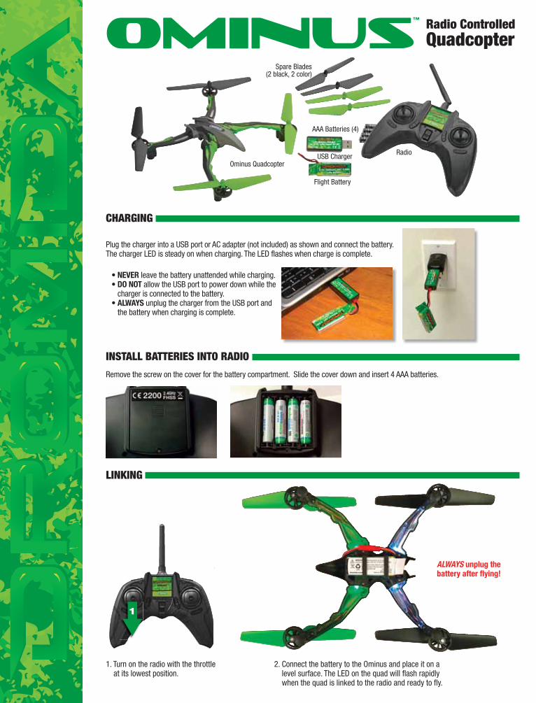
Ominus Quadcopter
Flight Battery
Spare Blades(2 black, 2 color)
AAA Batteries (4)
RadioUSB Charger
Radio ControlledQuadcopter
CHARGING
• NEVER leave the battery unattended while charging.• DO NOT allow the USB port to power down while the
charger is connected to the battery. • ALWAYS unplug the charger from the USB port and
the battery when charging is complete.
Plug the charger into a USB port or AC adapter (not included) as shown and connect the battery. The charger LED is steady on when charging. The LED flashes when charge is complete.
INSTALL BATTERIES INTO RADIO
Remove the screw on the cover for the battery compartment. Slide the cover down and insert 4 AAA batteries.
1
LINKING
1. Turn on the radio with the throttle at its lowest position.
2. Connect the battery to the Ominus and place it on a level surface. The LED on the quad will flash rapidly when the quad is linked to the radio and ready to fly.
ALWAYS unplug the battery after flying!
FLIGHT MODES
TROUBLESHOOTING PROBLEM: The quadcopter will not respond to the radio. SOLUTION: (1) Charge or change the battery on the quadcopter. (2) Turn off
the radio and disconnect the battery for the Ominus. Re-link the quadcopter and radio.
PROBLEM: Red radio LED light flashing after linking. SOLUTION: Replace with new AAA batteries.
PROBLEM: Unable to flip. SOLUTION: Battery voltage too low.
PROBLEM: Gyro not working properly. SOLUTION: (1) Battery voltage low. (2) Re-link. (3) Land onto the ground for 3
seconds and take off again.
PROBLEM: Will not take off. SOLUTION: Rotor blades incorrectly installed. See Rotor Blade Replacement
section.
PROBLEM: Quadcopter is shaking. SOLUTION: Check the canopy, chassis, motors and rotor blades for damage.
If the quadcopter is constantly drifting in the same direction or a new flight control board has been installed, the sensors on the Ominus should be calibrated.
1. Center all the trim adjustments. To check the trim, push the trim button once on one side and then once on the opposite side. When the trim is centered, the transmitter will emit a long, low pitched beep. The transmitter will emit a short beep of lower pitch as the adjustment gets closer to center and higher pitch as the adjustment moves away from center. Continue pressing the trim button that has the lower pitch until the adjustment is centered.
2. Link the quadcopter and the transmitter.3. Push down on the right stick and hold it. The radio will steadily beep while the stick is held down. 4. Press down on the left stick 3 times within 2 seconds. The radio will stop the steady beep and make a short beep when the stick is pressed the third time.5. Release both sticks and push up on the throttle trim button. The red LED will flash slowly and become steady again when the calibration is complete.6. Press down on the left stick to save the settings.
QUADCOPTER SENSOR CALIBRATION
LOW BATTERY INDICATOR The LEDs on the Ominus will flash slowly when the battery voltage is low. The Ominus should land as soon as possible to avoid damaging the battery. Always unplug the battery after flight. The battery needs to be charged before the quadcopter is stored.
Control sensitivity (Dual Rates) can be changed by pushing down on the right stick. The controller will make a short, low-pitched beep when changing to low rates. This mode should be used when flying indoors or if the pilot is not familiar with how the quadcopter responds to the controller. The controller will make a short, high-pitched beep when changing to high rates. This mode should be used when flying outdoors or when more agility is desired.
F- Mode LED off – Low RatesF-Mode LED on – High Rates
The low rate sensitivity of the controls is about 25% less than the high rate sensitivity. The overall controls can also be adjusted by
1. Holding down the right stick until the controller starts beeping. 2. Continue holding down the right stick and advance the throttle to the desired setting. 3. Release the right and return the throttle to 0%.
The default setting is when the throttle is at 50% (midstick).
To toggle between the normal and expert agility modes, press the F-Mode Button. When the accelerometers are off, the flight controller will make the Ominus more agile, but also it is easier to crash.
F-Mode LED steady (off or on) – Normal Mode, accelerometers onF-Mode LED flashing – Expert Mode, accelerometers off
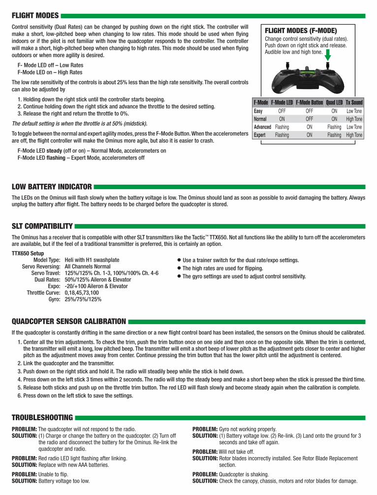
Change control sensitivity (dual rates). Push down on right stick and release. Audible low and high tone.
FLIGHT MODES (F-MODE)
Easy OFF OFFNormal ON OFF
Expert Flashing ONAdvanced Flashing ON
F-Mode F-Mode LED F-Mode ButtonON Low ToneON High Tone
Flashing High ToneFlashing Low Tone
Quad LED Tx Sound
The Ominus has a receiver that is compatible with other SLT transmitters like the Tactic™ TTX650. Not all functions like the ability to turn off the accelerometers are available, but if the feel of a traditional transmitter is preferred, this is certainly an option.
TTX650 Setup Model Type: Heli with H1 swashplate Servo Reversing: All Channels Normal Servo Travel: 125%/125% Ch. 1-3, 100%/100% Ch. 4-6 Dual Rates: 50%/125% Aileron & Elevator Expo: -20/+100 Aileron & Elevator Throttle Curve: 0,18,45,73,100 Gyro: 25%/75%/125%
SLT COMPATIBILITY
• Use a trainer switch for the dual rate/expo settings.
• The high rates are used for flipping.
• The gyro settings are used to adjust control sensitivity.
GEAR SHAFT REPLACEMENT
1. Remove the rotor blade from the gear shaft.2. Push the shaft down to remove it from the gear.3. Install the new gear shaft and rotor blade if it is not damaged.
Note: While the gear is out, check it carefully for any cracks or damage to the teeth.
MOTOR REPLACEMENT
1. Remove the screw securing the motor cover to the arm and pull to cover off the motor.
2. Use a small flat blade screwdriver to separate the motor plug from the socket. DO NOT pull the wires.
3. Remove the motor from the frame and insert the replacement. Make sure that the wire colors on the replacement motor are the same as the original. The motors for the clockwise props have black and white wires. The counter-clockwise props use motors with blue and red wires.
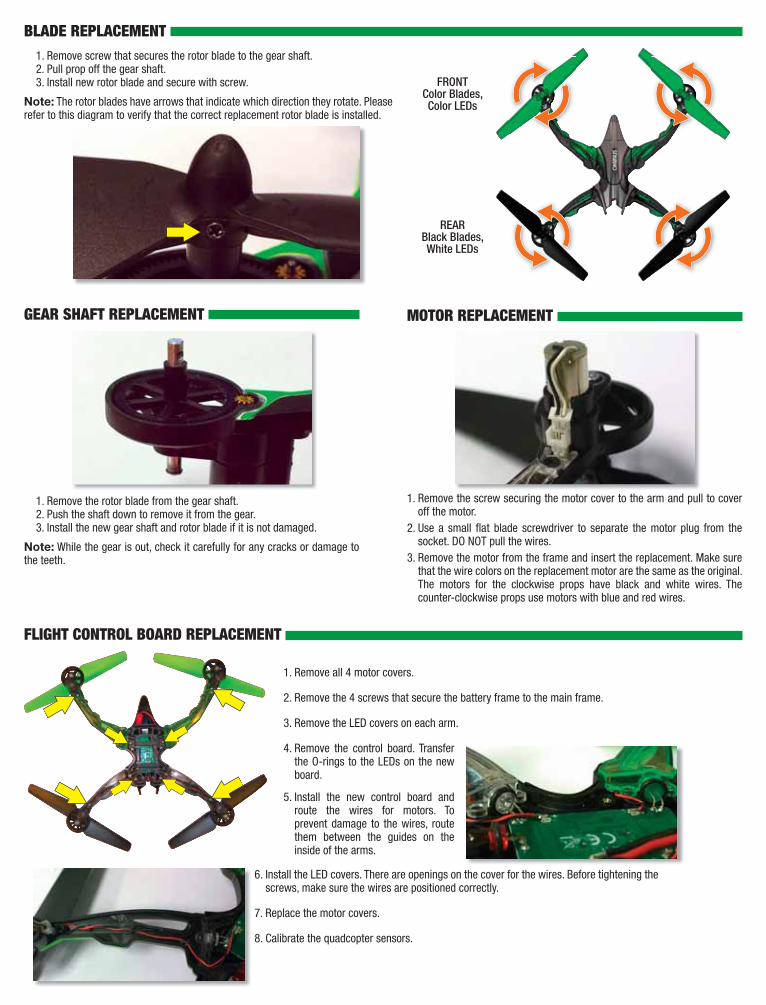
BLADE REPLACEMENT
FRONTColor Blades,Color LEDs
REARBlack Blades,White LEDs
1. Remove screw that secures the rotor blade to the gear shaft.2. Pull prop off the gear shaft.3. Install new rotor blade and secure with screw.
Note: The rotor blades have arrows that indicate which direction they rotate. Please refer to this diagram to verify that the correct replacement rotor blade is installed.
FLIGHT CONTROL BOARD REPLACEMENT
5. Install the new control board and route the wires for motors. To prevent damage to the wires, route them between the guides on the inside of the arms.
6. Install the LED covers. There are openings on the cover for the wires. Before tightening the screws, make sure the wires are positioned correctly.
7. Replace the motor covers.
8. Calibrate the quadcopter sensors.
1. Remove all 4 motor covers.
2. Remove the 4 screws that secure the battery frame to the main frame.
3. Remove the LED covers on each arm.
4. Remove the control board. Transfer the O-rings to the LEDs on the new board.
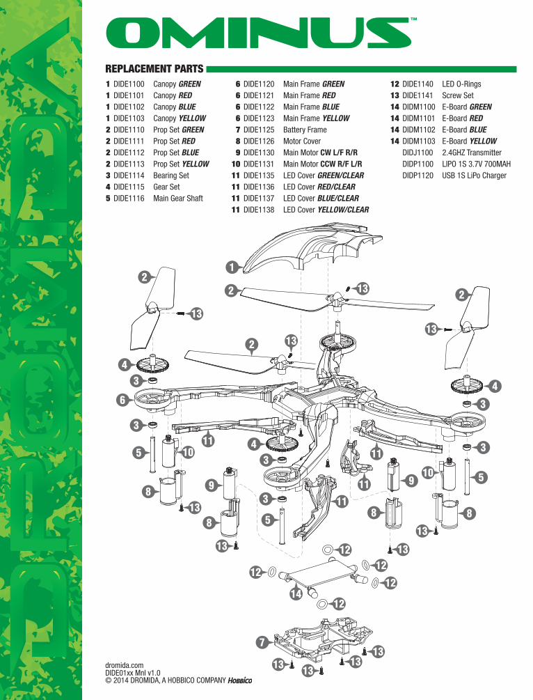
REPLACEMENT PARTS 1 DIDE1100 Canopy GREEN 1 DIDE1101 Canopy RED 1 DIDE1102 Canopy BLUE 1 DIDE1103 Canopy YELLOW 2 DIDE1110 Prop Set GREEN 2 DIDE1111 Prop Set RED 2 DIDE1112 Prop Set BLUE 2 DIDE1113 Prop Set YELLOW 3 DIDE1114 Bearing Set 4 DIDE1115 Gear Set 5 DIDE1116 Main Gear Shaft
6 DIDE1120 Main Frame GREEN 6 DIDE1121 Main Frame RED 6 DIDE1122 Main Frame BLUE 6 DIDE1123 Main Frame YELLOW 7 DIDE1125 Battery Frame 8 DIDE1126 Motor Cover 9 DIDE1130 Main Motor CW L/F R/R10 DIDE1131 Main Motor CCW R/F L/R11 DIDE1135 LED Cover GREEN/CLEAR11 DIDE1136 LED Cover RED/CLEAR11 DIDE1137 LED Cover BLUE/CLEAR11 DIDE1138 LED Cover YELLOW/CLEAR
12 DIDE1140 LED O-Rings13 DIDE1141 Screw Set14 DIDM1100 E-Board GREEN14 DIDM1101 E-Board RED14 DIDM1102 E-Board BLUE14 DIDM1103 E-Board YELLOW DIDJ1100 2.4GHZ Transmitter DIDP1100 LIPO 1S 3.7V 700MAH DIDP1120 USB 1S LiPo Charger
12
3
3
5
8
88
9
43
3
5
12
7
13
1313
13
10
13
4
6
2
13
13
10
13 11
9
1212
12
12
13
13
8
4
3
3
5
13
2 13
11
11
11
2
14
dromida.comDIDE01xx Mnl v1.0 © 2014 DROMIDA, A HOBBICO COMPANY
™