qualification of the titanium welds in the e-xfel...
TRANSCRIPT
QUALIFICATION OF THE TITANIUM WELDS IN THE E-XFEL CRYOMODULE AND CE CERTIFICATION
S. Barbanotti#, H. Hintz, K. Jensch, R. Klos, W. Maschmann, A. Matheisen, A. Schmidt, DESY, Hamburg, Germany
C. Boulch, J.P. Charrier, C. Cloué, C. Madec, O. Napoly, J.L. Perrin, Y. Sauce, T. Trublet, CEA/DSM/Irfu, Saclay, France
Abstract The CE stamping of the one hundred 1.3 GHz
cryomodules for the European XFEL Linac is a main step in the process of the certification of the entire Linac as pressure equipment. Stringent requirements on materials and the quality of the welds of the pressurised components need to be satisfied to obtain the stamp. This paper summarizes these requirements, describes the process developed to qualify each module and summarises the rework campaign on the cavity helium vessels made necessary to obtain the required quality for a reliable and safe accelerator.
INTRODUCTION The European XFEL linac has to fulfil for operation the
requirements of the “Betriebsicherheitsverordung” (German implementation of the European Directive 2009/104/EC “use of work equipment”). In Hamburg, where the linac will be installed and brought into operation, this means that the linac needs for operation the approval from the “Amt für Arbeitsschutz (AfA, HH)” (office for work safety).
The AfA does not verify the facility itself; the certification (e.g. CE marking) is done via a notified body (in the XFEL case, the TÜV Nord [1]). The CE marking is the manufacturer's declaration that the product meets the requirements of the applicable EC directives. For the XFEL, this means that the cold linac has to be conform to the Pressure Equipment Directive PED (97/23/EC) [2].
XFEL CRYOMODULE CERTIFICATION The cold XFEL linac is an assembly of 100
cryomodules, ~ 100 sets of bellows for the cryomodule connections, string connection boxes and End/Feed caps with relief valves. Bellows, boxes and caps have a declaration of conformity to the PED or are already CE marked at the delivery, while the cryomodules are marked during the assembly process under DESY responsibility at CEA-Saclay.
Each XFEL cryomodule is an assembly, made of the following PED-relevant sub-components: 8 cavities, 1 quadrupole, 7 titanium bellows, 1 end connection, 1 quadrupole pipe and 1 cold mass (also an assembly of cooling pipes and heat exchangers). Each component is independently certified as “part of pressure equipment” by a notified body or by DESY (as an approved manufacturer according to AD2000 HP0 and EN3834).
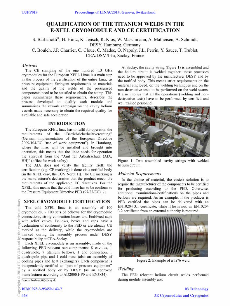
At Saclay, the cavity string (figure 1) is assembled and the helium circuit is welded together; these processes need to be approved by the manufacturer DESY and by the notified body. This means strict requirements on the material employed, on the welding techniques and on the non-destructive tests to be performed on the weld seams. It also implies that all the operations (welding and non-destructive tests) have to be performed by certified and well trained personnel.
Material Requirements In the choice of material, the easiest solution is to
require the manufacturer of the components to be certified for producing according to the PED. Otherwise, additional examinations/certifications on the pipes and bellows are required. As an example, if the producer is PED certified the pipes can be delivered with an EN10204 3.1 certificate, while if he is not, an EN10204 3.2 certificate from an external authority is required.
Welding The PED relevant helium circuit welds performed
during module assembly are:
Figure 1: Two assembled cavity strings with welded helium circuit.
Figure 2: Example of a Ti76 weld
___________________________________________ #[email protected]
TUPP019 Proceedings of LINAC2014, Geneva, Switzerland
ISBN 978-3-95450-142-7
468Cop
yrig
ht©
2014
CC
-BY-
3.0
and
byth
ere
spec
tive
auth
ors
03 Technology
3E Cryomodules and Cryogenics
16 orbital welds on the titanium 76.1x2 mm pipe (Ti76, also shown in figure 2)
1 orbital weld on the stainless steel (SS) 42.4 mm pipe (SS42)
9 orbital welds on the SS 8 mm warm up pipe capillaries
2 tack welds on the SS warm up pipe 2 lip welds on the SS quadrupole assembly
Non-Destructive Tests (NDT) The NDT on the PED relevant welds for the XFEL
cryomodule, as finally agreed with TÜV Nord, are: for all the welds: 100% visual test and 100% leak
test for the orbital welds Ti76: 100% radiography test
(RT) for the orbital weld SS42: 1 every 10 welds 100%
RT, the others 100% liquid penetrant test (PT) for the lip welds and the tack welds: 100% PT.
RESULTS FOR THE FIRST CRYOMODULES
The complete procedure, including all the NDT, was applied for the first time in September 2013 to the XM-1 cryomodule. The results were satisfactory for all the welds except the Ti76 welds, where non-acceptable pores were present in many welds.
Figure 3: Pores in an orbital weld
Pores (figure 3) are one of the main defects that can appear during titanium welding. Titanium is a getter material and can easily attract impurities, coming from a non-perfectly clean environment or non-careful handling during welding. Pre-existing pores can also be present in the material to be welded and can contribute to the formation of new and bigger pores.
Pores are qualified depending on their diameter; the norm DIN EN ISO 10675-1 defines the acceptance levels for pores in the X-ray results. For a pipe with 2 mm wall thickness, the levels are:
Level 1: diameter ≤ 0.4 mm (20% pipe thickness) Level 2: diameter ≤ 0.6 mm (30% pipe thickness) Level 3: diameter ≤ 0.8 mm (40% pipe thickness)
Specifications of the 2-phase line Ti pipe for the XFEL 1.3 GHz cavities allow “ASME like” quality, with pores level 3 (agreement between DESY and TÜV Nord); the
PED requires pores level 3, but DESY (as manufacturer of the XFEL cryomodules) accepts only pores level 1.
Why the Level 1 Requirement? The PED defines minimum requirements for the safe
operation of an assembly; it doesn‘t guarantee that the object can be operated at the desired quality level for the whole operation time. The manufacturer of an assembly (DESY for the XFEL cold linac) is responsible for the safety and the quality of the assembly itself and can therefore enforce additional requirements, not foreseen in the norm.
The XFEL requires a 20 years operation time without possibility of repairs on assembled modules. DESY accepts therefore only level 1 pores in the Ti76 welds to minimise the risk of failures during the 20 years operation period of the linac.
Moreover, the quality of the assembly has a direct impact on the future inspection plan. If a component is built to the limit of the values allowed by the norm, the external authority can decide that in-service inspections (periodical reviews of the assembly) are necessary after the first commissioning. This is something that should absolutely be avoided for the XFEL and is therefore another reason to set the acceptance level for the X-ray pictures at level 1, far away from the norm limit.
How to Reduce Pore Number and Dimension After the pores appeared at the first X-ray campaign,
the following actions have been taken: in the welding workshop, better preparation and cleanness were enforced; parasitic building ventilation (heating, doors) was set under control and the welding tooling was improved (a metallic welding bladder was exchanged with an external support and a rubber inner bladder); the quality of the welding gas mixture He-Ar (50%-50%) was carefully checked and the bottles brought to room temperature before the beginning of the welding operation; the Ti bellows were ultrasonic cleaned and, finally, the decision was taken to exchange all the longitudinally welded pipes on the cavity tanks with seamless pipes.
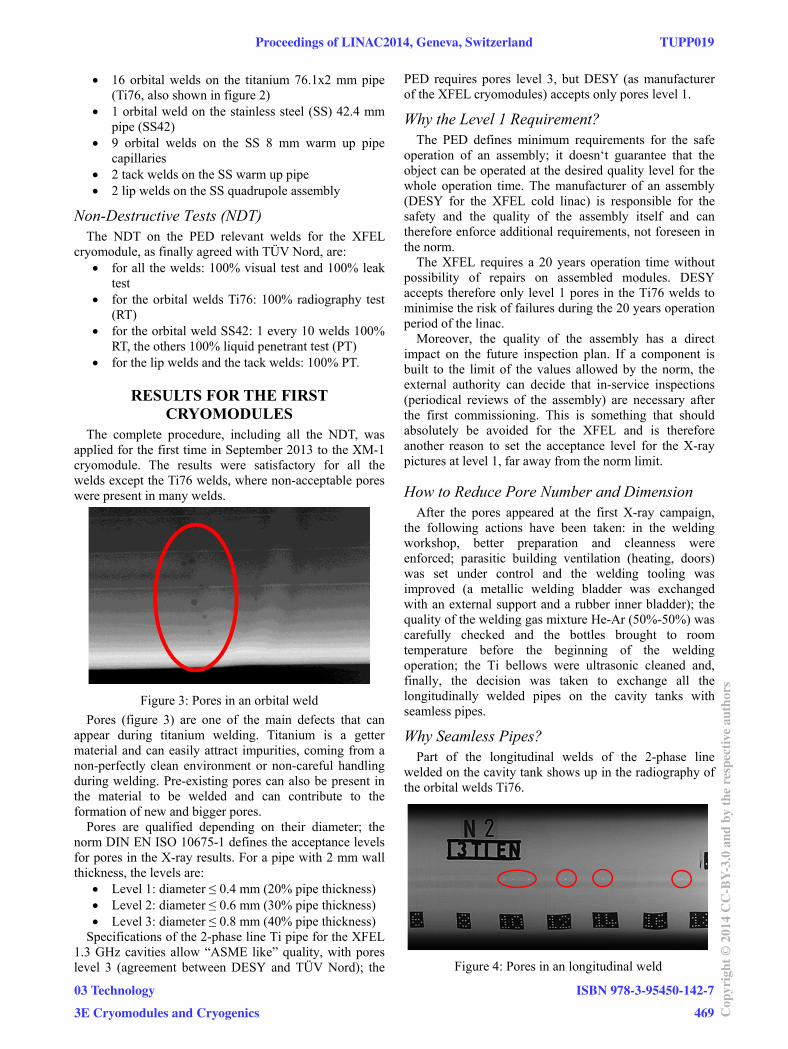
Why Seamless Pipes? Part of the longitudinal welds of the 2-phase line
welded on the cavity tank shows up in the radiography of the orbital welds Ti76.
Figure 4: Pores in an longitudinal weld
Proceedings of LINAC2014, Geneva, Switzerland TUPP019
03 Technology
3E Cryomodules and Cryogenics
ISBN 978-3-95450-142-7
469 Cop
yrig
ht©
2014
CC
-BY-
3.0
and
byth
ere
spec
tive
auth
ors

For the PED, the cryomodule is not acceptable, if one single pore > 0.8 mm shows up in the longitudinal weld X-ray picture (figure 4), even if the cavity is pressure tested, leak tested and already certified by the TÜV.
Even if the pre-existing pores are <0.8 mm, welding experts suspects that one or more pores close to the pipe end can be re-melted and included in the new weld, causing bigger pores on the orbital weld itself.
The first welding campaigns on the cryomodules and some additional X-ray campaigns performed on the longitudinal welds themselves showed a low quality in the longitudinal welds of many pipes. Therefore the decision was taken to replace all the longitudinally welded pipes starting from the cryomodule XM5.
THE 2-PHASE PIPE REPAIR The repair work consists of replacing with seamless
pipes the parts shown in orange in Figure 5 for each cavity with longitudinally welded pipes. To do this, first of all, for each cavity, the region around the T-connection (in green in figure 5) is X-rayed to verify the absence of pores >0.4 in the T-piece and in the cutting region. If
pores are visible in the cutting area the cutting region is modified and the cavity undergoes a special repair program (special length pipes are needed). The cavities with pores >0.4 mm in the T-piece are temporary set aside and will be handled all together at the end of the standard repair works (repair of the pores or exchange of the complete T-piece are under discussion). In the standard repair program, the two ends of the pipe are cut, trimmed and prepared for welding (figure 6). After the welding of
the seamless pipes, the new orbital welds are visually inspected, leak checked and X-rayed (acceptance fixed at level 1). If all the tests are successful (and the cavity has
undergone the standard vertical RF test), the cavity is ready for installation in a module. Otherwise an additional repair work is needed.
Statistics of the Repair Work Since March 2014 ~150 cavities have been repaired and
are ready for module assembly. If we look at the X-ray results of the longitudinal welds
(before the repair) >250 cavities have been tested (~0.4 m longitudinal weld for each cavity) and >1000 pores found, the most between 0.2 and 0.9 mm. The biggest pore is ~1.5 mm (75% of the 2 mm wall thickness). These values proof the pore quality of the longitudinally welded pipes.
X-RAY RESULTS OF THE CRYO-MODULES WITH SEAMLESS PIPES
Table 1 summarises the results of the first X-ray campaign for each cryomodule with seamless 2-phase pipes on the cavities. The cryomodules XM5 to XM11 were welded by a new company (new personnel, with no experience on cryomodule welding). Since the results were not satisfactory, DESY temporary took charge of the welding operations in July 2014 starting with the cryomodule XM12 and welded a level 1 module at the first attempt, proving the feasibility of the level 1 requirement.
Table 1: Ti welds X-ray results of assembled modules
ModuleNo
pores Level Pores
>0.8 mm Repair
1 2 3
XM5 3 2 7 4 0 level 2
XM6 2 7 3 4 0 no
XM7 3 9 3 1 0 no
XM8 2 10 2 2 0 level 2
XM9 7 4 4 1 0 level 3
XM10 9 3 1 1 2 level 2
XM11 4 6 3 2 1 level 2
XM12 7 9 0 0 0 no
CONCLUSIONS The process to obtain the PED certification for the
XFEL cryomodules is now well defined and the first 10 modules are on the way to be certified.
However, the CE marking does not guarantee a 20 year operation of the XFEL linac at the required quality levels.
Therefore more stringent requirements on the X-ray results of the Ti welds have been enforced, making necessary an extensive repair campaign on the cavity 2-phase pipes. The repair work is now running smoothly in DESY and has been completed for 25% of the cavities.
REFERENCES [1] http://www.tuv-nord.com/en [2] http://ec.europa.eu/enterprise/sectors/pressure-and-
gas/documents/ped/index_en.htm
Figure 5: Sketch of the repair work.
Figure 6: Welding a seamless pipe
TUPP019 Proceedings of LINAC2014, Geneva, Switzerland
ISBN 978-3-95450-142-7
470Cop
yrig
ht©
2014
CC
-BY-
3.0
and
byth
ere
spec
tive
auth
ors
03 Technology
3E Cryomodules and Cryogenics