qualifying and troubleshooting cable broadband pons€¦ · qualifying and troubleshooting cable...
TRANSCRIPT

RM SCTE Webinar: All things Optical / PHY 1
Qualifying and Troubleshooting Cable Broadband PONs
RM SCTE Webinar – All Things Optical / PHY
13-Apr-2017
Michael Scholten, Sr. Product Marketing Mgr, AFL

Presentation Outline
Introduction – Market Drivers for MSO PON Deployment
MSO Passive Optical Network (PON) Architectures
RFoG PON Architecture
GPON / EPON Architecture
Fiber Test Basics
Connector Inspection & Cleaning
Insertion Loss Testing
OTDR Testing
Qualifying and Troubleshooting PONs
What’s Different when Testing a PON?
Out-of-service PON Installation Verification
What’s Unique about Testing a Live (In-service) PON?
Live PON Troubleshooting
Summary and Q & A
RM SCTE Webinar: All things Optical / PHY 2

Bandwidth demand continues to skyrocket
4K and HDR video coming
Over-the-top (OTT) video
Online all-the-time society
Upstream bandwidth demand challenging
traditional CATV network architecture
(e.g. video upload)
RFoG, node splitting, DOCSIS 3.1 offer near-term solutions
More and more MSOs considering or deploying GPON/EPON architecture
Service Providers looking to converge business and residential networks
PON standards in place to grow bandwidth to 10Gb/s and 40Gb/s
XG-PON / 10GEPON – 10 Gb/s asymmetric
XGS-PON – 10 Gb/s symmetric
NG-PON2 – Up to 4 x 10Gb/s symmetric; Also supports WDM-PON
Market Drivers for MSO PON Deployment
3RM SCTE Webinar: All things Optical / PHY

MSO Network Architectures to Address BW Demand
RM SCTE Webinar: All things Optical / PHY 4
RFoG PON Architecture
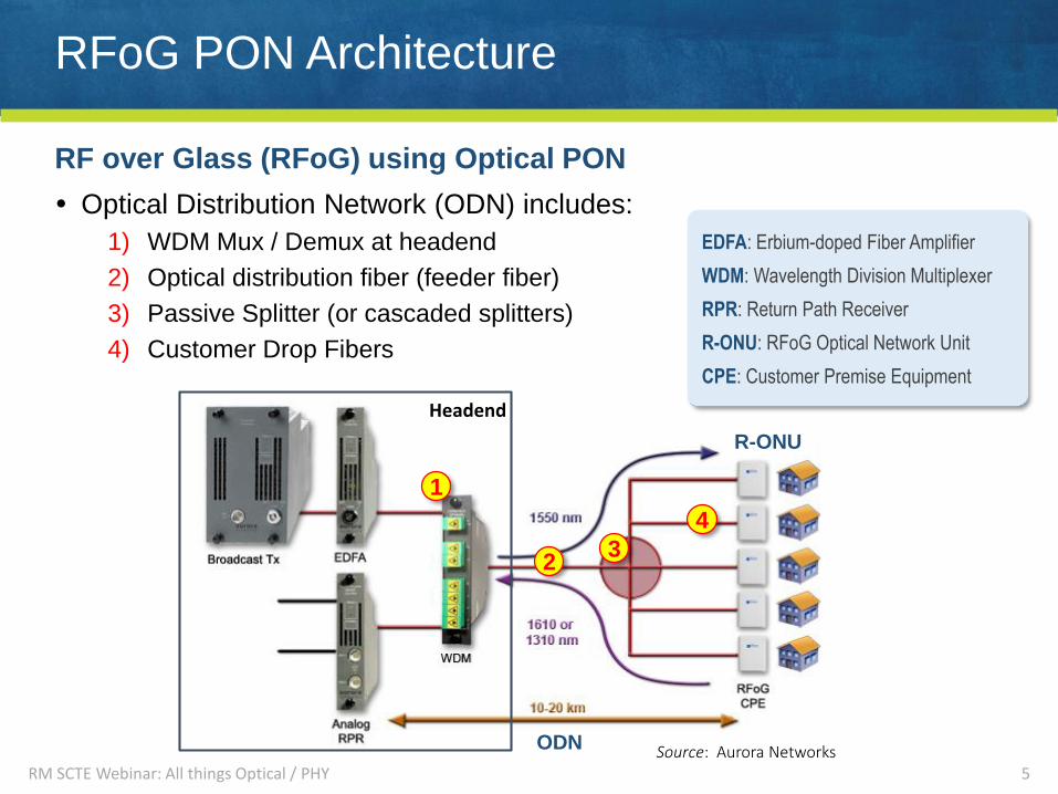
RF over Glass (RFoG) using Optical PON
Optical Distribution Network (ODN) includes:
1) WDM Mux / Demux at headend
2) Optical distribution fiber (feeder fiber)
3) Passive Splitter (or cascaded splitters)
4) Customer Drop Fibers
5Source: Aurora Networks
Headend
R-ONU
ODN
RM SCTE Webinar: All things Optical / PHY
1
23
4
EDFA: Erbium-doped Fiber Amplifier
WDM: Wavelength Division Multiplexer
RPR: Return Path Receiver
R-ONU: RFoG Optical Network Unit
CPE: Customer Premise Equipment
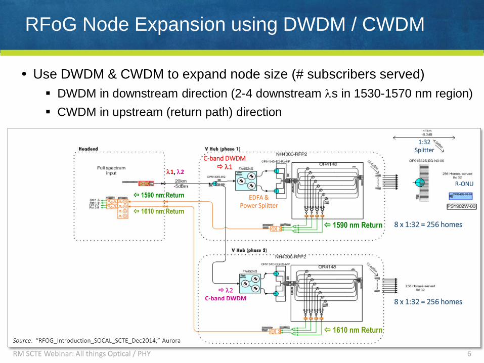
Source: “RFOG_Introduction_SOCAL_SCTE_Dec2014,” Aurora
RFoG Node Expansion using DWDM / CWDM
Use DWDM & CWDM to expand node size (# subscribers served)
DWDM in downstream direction (2-4 downstream s in 1530-1570 nm region)
CWDM in upstream (return path) direction
6
8 x 1:32 = 256 homes
8 x 1:32 = 256 homes
C-band DWDM 1
2C-band DWDM
1590 nm Return
1610 nm Return
1590 nm Return
1610 nm Return
1, 2
EDFA &Power Splitter
1:32Splitter
R-ONU
RM SCTE Webinar: All things Optical / PHY

GPON / EPON Network Architecture
GPON / EPON deliver voice, internet & video to homes
7
ONT
OLT
FDH
Access
Terminal
PON Splitter
Located
at FDH…
…and/or
Access
Terminal
Headend
RM SCTE Webinar: All things Optical / PHY
1490 nm
1550 nm 1310 nm

MDU FTTP PON Architecture
8
MDU Application:
Splitters typically installed in MDU
ground floor
Distributed splitter architecture
possible depending on MDU size
Access points in telecom closets
ONTs installed inside individual
apartments
RM SCTE Webinar: All things Optical / PHY

Fiber Test Basics- Inspection & Cleaning
- Insertion Loss Testing
- OTDR Testing
RM SCTE Webinar: All things Optical / PHY 9

Importance of Cleaning
#1 Problem: Dirty / Damaged Connectors!
“98% of installers and 80% of network owners reported that issues with
connector contamination were the greatest cause of network failure”
10RM SCTE Webinar: All things Optical / PHY
Source: NTT Advanced Technology

B: Cladding
Unacceptable single-mode end-face
Connector End-Face Inspection
RM SCTE Webinar: All things Optical / PHY 11
Zone Scratches DefectsA: Core
(0 - 25 m)Max 4 3 m None allowed
B: Cladding(25 - 115 m)
No Limit No limit < 2 mMax 5 from 2 - 5 m
None > 5 m
C: Adhesive(115 - 135 m)
No Limit No Limit
D: Contact(135 - 250 m)
No Limit None > 10 m
A: Core
C: Adhesive
D: Contact
IEC 61300-3-35 Pass/Fail Criteria: SM, APCAcceptable single-mode end-face
FOCIS FlexConnector Inspection
Video scope
Note: Pass/fail criteria depends on fiber type, connector type & polish
Contamination
or Pitting

One-Click
Cleaners
Wet and Dry Cleaning
RM SCTE Webinar: All things Optical / PHY 12
One-Click Cleaners (dry cleaning) Easy, fast & effective; Low cost per clean
Cleans jumper connector ends
Cleans through patch panels
Solution & Wipes (wet cleaning) Effective on stubborn contamination
Use solution which leaves no residue
Wipes or absorbent sticks to dry
Use sticks to clean through bulkheads
Clean both connectors of a mated pair every time you connect!
Ultra
One-Click
Mini
One-Click
Cleaners
Cleaning
Fluid
Tape
Cleaner
Cleaning
Sticks
Fiber Test Basics: Insertion Loss Testing
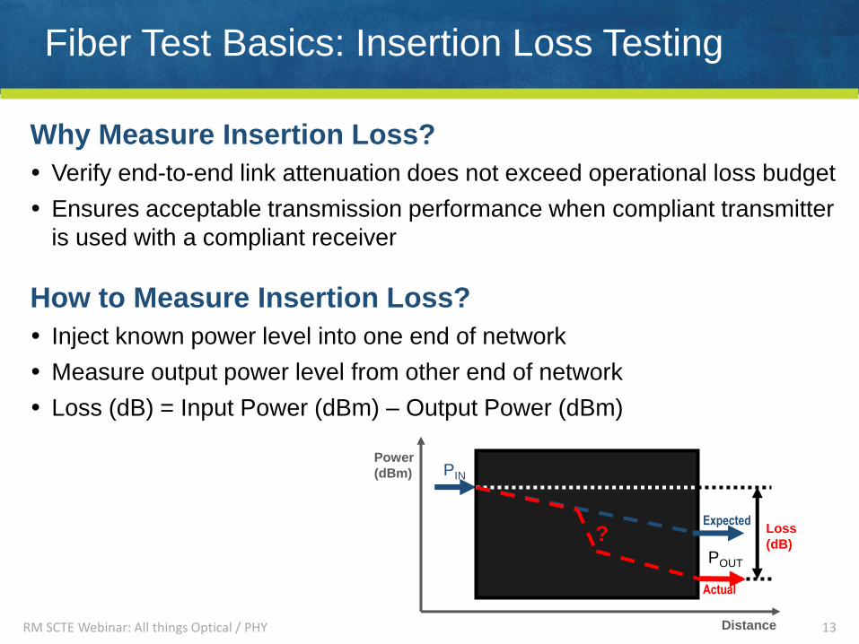
Why Measure Insertion Loss?
Verify end-to-end link attenuation does not exceed operational loss budget
Ensures acceptable transmission performance when compliant transmitter
is used with a compliant receiver
How to Measure Insertion Loss?
Inject known power level into one end of network
Measure output power level from other end of network
Loss (dB) = Input Power (dBm) – Output Power (dBm)
13RM SCTE Webinar: All things Optical / PHY
Power
(dBm)
Distance
? Loss
(dB)
PIN
POUT
Actual
Expected

Fiber Test Basics: Measuring Insertion Loss
Measure Loss using an Optical Light Source + Optical Power Meter
14
1) Set reference
Light Source
Tx
Optical PowerMeter
Rx
TX cord
PIN = -1.0 dBm
Measure PIN and store it
as the 0 dB reference level.
0 dB
RX cord
Connection (two connectors mated
through an adapter)
Tx
Optical PowerMeter
Rx
Light Source
2) Check test cords
TX cord
Allowed insertion loss
depends on connector type.
0.4 dB
RM SCTE Webinar: All things Optical / PHY
Fiber Test Basics: Measuring Insertion Loss
15
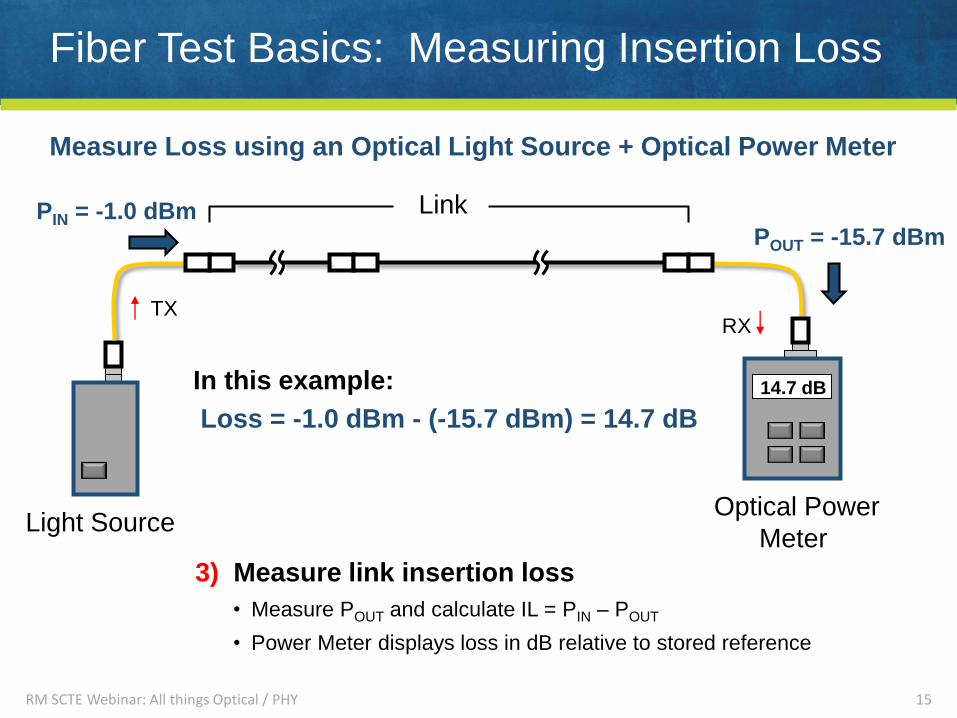
Measure Loss using an Optical Light Source + Optical Power Meter
RX
Optical Power
Meter Light Source
TX
In this example:
Loss = -1.0 dBm - (-15.7 dBm) = 14.7 dB
POUT = -15.7 dBm
3) Measure link insertion loss
• Measure POUT and calculate IL = PIN – POUT
• Power Meter displays loss in dB relative to stored reference
14.7 dB
LinkPIN = -1.0 dBm
RM SCTE Webinar: All things Optical / PHY
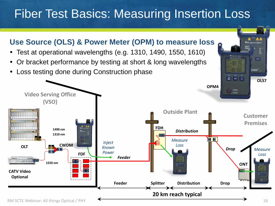
Fiber Test Basics: Measuring Insertion Loss
Use Source (OLS) & Power Meter (OPM) to measure loss
Test at operational wavelengths (e.g. 1310, 1490, 1550, 1610)
Or bracket performance by testing at short & long wavelengths
Loss testing done during Construction phase
16
Video Serving Office (VSO)
CustomerPremises
OLT
Feeder
Distribution
DropCWDM
FDF
Feeder Splitter Distribution Drop
20 km reach typical
1490 nm
1310 nm
1550 nm ONT
CATV Video Optional
Outside Plant
FDH
InjectKnownPower
MeasureLoss
MeasureLoss
OLS7
OPM4
RM SCTE Webinar: All things Optical / PHY

Fiber Test Basics: Measuring Insertion Loss
An OLS/OPM can only measure end to end loss.
If loss is excessive, how can one determine cause?
17
Power
(dBm)
Distance
? Loss
(dB)
PIN
POUT
Actual
Expected
RM SCTE Webinar: All things Optical / PHY

Fiber Test Basics: OTDR Testing
An OTDR is a one-dimensional optical “radar”:
Injects pulses of light, measures the amplitude and time of flight of
backscattered and reflected light guided back up the fiber
Converts time-of-flight into distance based on speed of light in glass
Plots returned signal level vs. distance
OTDR can measure the loss of fiber sections, as well as the loss and
reflectance of connections, splices, splitters, macrobends or breaks.
18
PIN
POUTFiber
Reflective
Connector
Non-reflective
SpliceReflective
Connector
Reflective
Connector
RM SCTE Webinar: All things Optical / PHY Distance
Relative
Power
(dB)
Unique Challenges when Testing a PON
RM SCTE Webinar: All things Optical / PHY 19

What’s Unique When Testing a PON?
1) Normal trace up to the splitter
2) Backscatter & reflections from fibers overlap beyond splitter
Unacceptable loss in one drop fiber hidden by backscatter and reflections from
overlapping drop fibers
• Example: 3 dB loss in 1 leg = 0.06 dB in combined backscatter from 32 legs!
Even if fault detected, no way to determine which leg has the problem
3) Splitter appears as high-loss event -- Could be declared as fiber end
20
If OTDR test attempted from the OLT end:
12
3
Conclusion
Test from ONT end to reliably detect
faults in distribution and drop fibers.
1x3
2
Feeder Fiber
Drop Fiber
ONTEnd
OLTEnd
RM SCTE Webinar: All things Optical / PHY

Mind Your Connectors!
FTTx PONs are usually built with angle-polished connectors
Ensures unused (open) splitter ports won’t generate strong reflections which could
disrupt PON operation, especially with 1550 nm video overlay
OTDRs may be built with either 90o SC-UPC or angled SC-APC connectors
SC-UPC more commonly used in non-PON applications
CAUTION: Do not mate UPC connectors to APC connectors!
Mated UPC APC results in excess reflection and loss
Poor OTDR results will be obtained when mismatched connectors mated
Use SC-UPC to SC-APC hybrid jumpers or launch cables as necessary to connect
OTDR with SC-UPC to SC-APC PON connectors
21
SC-UPC SC-APC
Air gap when mating SC-UPC
to SC-APC results in excess
reflection & loss Excess reflection at front panel
Ghost reflection (re-reflection)
Long recovery tail
RM SCTE Webinar: All things Optical / PHY
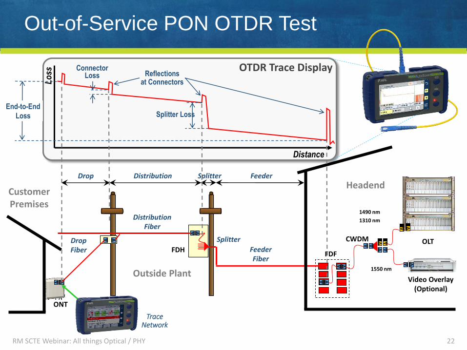
OTDR Trace Display
Distance
Lo
ss
Out-of-Service PON OTDR Test
22
OLTFeederFiber
DistributionFiber
DropFiber
CWDM
FDF
1490 nm
1310 nm
1550 nm
ONT
FeederSplitterDistributionDrop
Splitter Loss
ConnectorLoss
End-to-End
Loss
CustomerPremises
Outside Plant
TraceNetwork
Reflectionsat Connectors
FDH
Splitter
Video Overlay(Optional)
Headend
RM SCTE Webinar: All things Optical / PHY
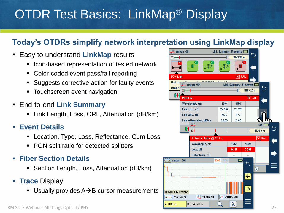
OTDR Test Basics: LinkMap Display
Easy to understand LinkMap results
Icon-based representation of tested network
Color-coded event pass/fail reporting
Suggests corrective action for faulty events
Touchscreen event navigation
End-to-end Link Summary
Link Length, Loss, ORL, Attenuation (dB/km)
Event Details
Location, Type, Loss, Reflectance, Cum Loss
PON split ratio for detected splitters
Fiber Section Details
Section Length, Loss, Attenuation (dB/km)
Trace Display
Usually provides AB cursor measurements
23
Today’s OTDRs simplify network interpretation using LinkMap display
RM SCTE Webinar: All things Optical / PHY

OTDR Test Basics: Range / Resolution Tradeoff
OTDR Pulse Width affects trace signal level and event resolution
Multi-pulse acquisition offers high resolution plus high dynamic range
24
Narrow Pulse Width:
Trace “disappears”
into noise floor.
Link
Wider Pulse Width:
Events can be seen
and trace is smooth.
Link
Widest Pulse Width:
Can’t resolve events
Link
Overlapping pulses
hide event
RM SCTE Webinar: All things Optical / PHY

What’s Unique when Testing a Live PON?
One subscriber may lose service while others remain in-service
Network continues to transmit 1310/1610, 1490, and 1550 nm signals
Check downstream PON power levels at out-of-service ONT:
OK: Power at 1490 & 1550 nm wavelengths within expected levels
Dim or Dark: Little or no 1490 and/or 1550 nm power due to upstream fault
Cannot test a live PON using a standard OTDR!
OTDR test at 1310, 1490, or 1550 nm will disrupt service to other customers!
Downstream 1490 or 1550 nm signals interfere with normal OTDR’s receiver
Test in-service PON using a Live PON OTDR which includes:
An OTDR laser at an out-of-band wavelength (e.g. 1625 or 1650 nm)
A filtered detector to reject in-service wavelengths (e.g. 1490, 1550)
25
1260
Down VideoRFoG/PON Wavelengths1290 1330
Up
1480 1500 1550 1560
O - Band E - Band S - Band C-Band L - Band
1360 1460 1530 1565 1625 1675 nm
U - Band
Test
1625 1650
RFoG Up
1610
RM SCTE Webinar: All things Optical / PHY
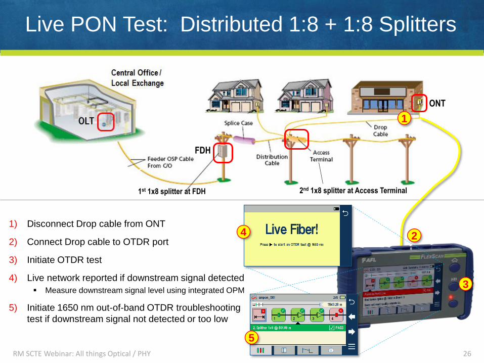
Live PON Test: Distributed 1:8 + 1:8 Splitters
1) Disconnect Drop cable from ONT
2) Connect Drop cable to OTDR port
3) Initiate OTDR test
4) Live network reported if downstream signal detected
Measure downstream signal level using integrated OPM
5) Initiate 1650 nm out-of-band OTDR troubleshooting
test if downstream signal not detected or too low
26
ONT
FDH
1st 1x8 splitter at FDH 2nd 1x8 splitter at Access Terminal
RM SCTE Webinar: All things Optical / PHY
1
2
3
4
5
PON Testing Summary
MSOs responding to residential and business broadband demand by
deploying Passive Optical Network (PON) architectures
Higher broadband speeds demand lower optical Insertion Loss (IL) and
higher Optical Return Loss (ORL)
Connector inspection and cleaning becoming more critical
End-to-end IL & ORL tests provide go / no-go assessment of both PON
and point-to-point network performance
OTDR testing required to ID root cause of networks failing IL / ORL tests
PON testing requires unique OTDR testing strategy and capabilities
Test upstream from ONT to obtain understandable, actionable results
Ensure OTDR will not inject 1310, 1490, 1550 nm test signals into live PONs
Test in-service PONs using out-of-band wavelength with filtered detector
27RM SCTE Webinar: All things Optical / PHY

www.AFLglobal.com
Thank You!Questions?
www.AFLglobal.com
28RM SCTE Webinar: All things Optical / PHY