quality assurance for prefabricated timber roof … · mitek asia sdn. bhd. pertubuhan arkitek...
TRANSCRIPT


i
QUALITY ASSURANCE FOR PREFABRICATED TIMBER ROOF TRUSS SYSTEMS

ii
Quality Assurance for Prefabricated Timber Roof Truss Systems
© Construction Industry Development Board Malaysia 2018
All enquiries regarding this book should be forwarded to:
Chief ExecutiveConstruction Industry Development Board MalaysiaLevel 10, Menara Dato’ Onn, Pusat Dagangan Dunia Putra,No 45, Jalan Tun Ismail, 50480 Kuala Lumpur, Malaysia.
Tel : 603-4047 7000Fax : 603-4047 7070Email : [email protected] : www.cidb.gov.my
No part of this publication may be reproduced or transmitted in any form or by any means, whether mechanical or electronic, including photocopying and recording, without the written consent of CIDB.
Perpustakaan Negara Malaysia Cataloguing-in-Publication Data

iii
TABLE OF CONTENTS
Committee Representation viPreface vii
SECTION 1: GENERAL 11.1 Scope 11.2 Normative references 11.3 Termsanddefinitions 21.4 Abbreviations 4
SECTION 2: TRUSS DESIGN PROCESS 42.1 General 42.2 Documentation or records 52.2.1 Information required before commencement of design process 52.2.2 Discrepancies or deviations from drawings supplied 52.2.3 Information to be provided on truss design designs 62.3 Checking parameters 72.4 Checking personnel 72.5 Frequency of checks 82.6 Acceptance criteria 82.7 Verificationoftrussdesigndrawings 82.8 Responsibilities of the main contractor 8
SECTION 3: TRUSS FABRICATION PROCESS 93.1 General 93.2 Documentation or records 93.2.1 Fabrication equipment 93.2.2 Timber 93.2.3 Assembly of truss components or fabrication process 103.2.4 Storage 103.3 Checking parameters 103.3.1 Fabrication equipment 103.3.2 Timber 113.3.3 Assembly of truss components 113.3.4 Storage 123.4 Checking format 123.4.1 Fabrication equipment 123.4.2 Timber 123.4.3 Assembly of truss components 123.4.4 Storage 123.5 Frequency of checks 13

iv
3.5.1 Fabrication equipment 133.5.2 Assembly of truss components 133.5.3 Storage 133.6 Acceptance criteria 133.6.1 Fabrication equipment 133.6.2 Assembly of truss components 133.6.2.1 For timber grade and species or strength group 143.6.2.2 For timber treatment 143.6.2.3 For timber sizes 143.6.2.4 For assembly and fabrication process 153.6.3 Storage 163.7 Verificationandtestingauthority 163.7.1 Fabrication equipment 163.7.2 Timber 163.8 Rectificationoftrussesinfactory 16
SECTION 4: SITE INSTALLATION PROCESS 174.1 General 174.2 Documentation or records 174.3 Checking parameters 174.4 Checking format 184.5 Frequency of checks 184.6 Acceptance criteria 194.7 Verificationoftrussdesigndrawings 194.8 Rectificationoftrussesonsite 20
SECTION 5: QUALITY ASSURANCE AUDIT TEAM 205.1 System Provider (SP) 205.2 Truss fabricator 205.3 Fabricator human resources 21
Annex A. Steel in connector manufacturing 22
Annex B. Summary of documentations and inspections 25
AnnexC.Processflowcharts 26 • FC1Totalsystemqualitycheck 27 • FC2.1Trussplantequipmentmaintenanceprocess 28 • FC2.2Trussplantequipmentmaintenanceprocess(continued) 29 • FC3Timberselectioncheckontrussplant 30 • FC4Stagesoftimberflow-Fabricatorwithlicensedtimbergrader 31

v
Annex D. Checklist 32 • CL1Checklistfortrussdesignanddetails 33 • CL2Checklistfortrussfabricatingequipment 36 • CL3Checklistfordocumentationforsitemeasurement 39 • CL4Checklistfortimberandtrussesattrussplant 40 • CL5Checklistfortrussinstallation 44
Annex E. MS 544: Part 2: 2001 Code of practice for structural use of 52 timber Part 2: Permissible stress design of solid timber - Appendix C. Grading of Malaysian structural timber
AnnexF.MS544:1978-TableA.1Classificationoftimbersinshrinkagegroup 61
Annex G. Terms applying to prefabricated timber roof trusses 63
Annex H. Some examples of truss fabrication defects involving the 64 teethed metal plate (nail plate) connectors
References 69Acknowledgment 70
LIST OF TABLETable 1 Roof truss installation tolerances 19
vi
COMMITTEE REPRESENTATION
This Construction Industry Standard (CIS) was developed and reviewed by the Construction Industry Development Board Malaysia with the assistance of the Technical Committee, which comprises representatives from the following organisations:
Board of Engineers Malaysia (BEM)Forest Research Institute Malaysia (FRIM)Haustek Engineering Sdn. Bhd.Institution of Engineers, MalaysiaJabatan Kerja Raya (JKR) Malaysian Timber Industry Board (MTIB)Malaysia Wood Industry AssociationMultinail Asia Sdn. Bhd.MiTek Asia Sdn. Bhd.Pertubuhan Arkitek Malaysia (PAM)Persatuan Pengusaha Kayu Kayan dan Perabot Bumiputera Malaysia (PEKA)Universiti Sains Malaysia (USM)Universiti Teknologi MARA (UiTM)

vii
PREFACE
Thisconstructionindustrystandardwasfirstdevelopedin2004andisrevisedasaqualityassurancefor prefabricated timber roof truss with the assistance of the Construction Industry Development Board (CIDB), which acted as a moderator and facilitator for the technical committee throughout the revision process of the standard.
The main objective for the development of the quality assurance is to establish a detailed and systematic framework to:
a) Ensure the quality of prefabricated timber trusses supplied to project sites are consistent with the standard set for the product
b) Establish a common standard of acceptance for all relevant parties involved in the construction of roof that uses such trusses (including project consultants and authorities)
c) Setminimumspecificationstobeusedbyconnectingplatesmanufacturersandtrussfabricators
d) Identifyrelevantpartieswiththenecessaryexpertiseforeachofthespecificareasforconductingthe internal and external audits for the processes concerned.
Compliance with this document does not in itself confer immunity from legal obligations.
1
QUALITY ASSURANCE FORPREFABRICATED TIMBER ROOF TRUSS SYSTEMS
SECTION 1: GENERAL
1.1 Scope
This Quality Assurance System covers the main elements of the prefabricated timber truss that encompasses:
i. Stage 1- Truss Design Process
ii. Stage 2 - Truss Fabrication Process
iii. Stage 3 - Site Installation Process
The relationship between each of these processes is illustrated in flow chart FC 1. Total System Quality Check. Some aspects are checked more than once as the product moves through the production chain. For instance, checks for defects in timber used for trusses, which exceeds the timber grading allowances, are carried out at Stage 2 and Stage 3.
1.2 Normative References
The referenced documents in this text constitute provisions of this Quality Assurance System. For dated references, where there are subsequent amendments to, or, revisions of, none of these publications apply. For undated references, the current edition of the publication is referred to and applied.
i. MS 360 Specification for Treatment of Timber with Copper/Chrome/ Arsenic Wood Preservatives
ii. MS 544-1 Code of Practice for Structural Use of Timber: Part 1: General
iii. MS 544-2 Code of Practice for Structural Use of Timber: Part 2: Permissible Stress Design of Solid Timber
iv. MS 544 Part 6 Code of Practice for Structural Use of Timber: Part 6: Workmanship, Inspection and Maintenance (First revision)
v. MS 1714 Specification for Visual Strength Grading of Tropical Hardwood Timber
vi. ANSI/TPI 1 National Design Standard for Metal Plate Connected Wood Truss Construction
viii. AS 1720.1 Timber Structures Part 1 - Design Methods
x. JIS G 3302: 1987 Hot-dip Zinc-coated Steel Sheet and Strip
xi. JKR 20601-0190-12 Specification for Prefabricated Timber Roof Trusses

2
xii. Malaysian Grading Rules for Sawn Hardwood Timber 2009 Edition
xiii. The system providers’ standards and specifications are derived from several companies, which are recognised by JKR.
1.3 TermsandDefinitions
For the purpose of this quality assurance system, the following terms and definitions apply.
i. Trusssystemdesigner(SD)
A Professional Engineer who is responsible for the design of the specified roof truss system or systems, and producing the required engineering design drawings based on the relevant standards approved by the supervising authority.
ii. Supervisingauthority(SA)
The authority responsible for ensuring that the contract work is done and completed, as specified in the contract within the stipulated period according to the accepted standards.
iii. Supervisingofficer(SO) A person who is responsible for ensuring that the contract work is done and completed, as
specified in the contract within the stipulated period according to the accepted standards.
iv. Trusssystemprovider(SP)
A supplier of a proprietary roof truss system, registered with MTIB.
v. Trusssystemfabricator
A manufacturer capable of fabricating and producing proprietary roof truss systems using equipment and tools approved by an established truss system provider.
vi. Trusssysteminstaller
The contractor appointed by the System Provider or fabricator to assemble, erect and install the specified proprietary roof truss system on site.
vii. Accreditedlaboratory
Laboratory accredited under the Malaysian Laboratory Accreditation Scheme (SAMM), or equivalent, which is approved by the Supervising Authority and System Provider.
viii. Maincontractor
A contractor defined in the main contract of work, who undertakes the obligation for the completion and delivery of work, as specified in the contract.
ix. Professionalengineer(PE)
Trained professional engineer who is registered with the Board of Engineers Malaysia (BEM) and is a current practitioner (having an active Practicing Certificate) in the registered field.

3
x. Projectconsultantengineer(CE)
A third-party professional engineer who is responsible in checking the structural drawings and all related engineering works, as specified in the work contract. In this quality assurance documentation, the Consultant Engineer is referred to as a consultant.
xi. Constructiondrawing
PE-approved drawing that represents the design principles and parameters, containing adequate information to produce fabrication drawings, and shall also contain adequate information on works to be done in the construction of all or a portion of the building structure.
xii. Fabricationdrawing
Drawing or set of drawings produced by the fabricator and verified by the PE to explain the fabrication and/or installation to the installation team. The fabrication drawings show more details than the construction drawings, but shall not modify the design principle and technical specification stipulated in the construction drawings.
xiii. As-builtdrawing
A revised set of drawings submitted by SP to the contractor showing the dimensions, geometry and location of all elements of the work to be completed under the contract.
xiv. Certifiedtreatedtimber Timber treated in accordance with MS 544 - Part 10, or any other equivalent standards,
accompanied by a treatment certificate or charge sheet, approved by MTIB.
xv. Pre-fabricatedtrusses
Truss fabricated in a controlled setting on assembly line in an off-site facility, then delivered and installed on site.
xvi. Certifiedpre-fabricatedtimberrooftruss
Roof truss fabricated in compliance with this Quality Assurance System by fabricators registered with MTIB that is approved by an established truss System Provider, who is also registered with MTIB.

4
1.4 Abbreviations
i. CIDB Construction Industry Development Board Malaysia
ii. FRIM Forest Research Institute Malaysia
iii. JKR Jabatan Kerja Raya (Public Works Department)
iv. MTIB Malaysian Timber Industry Board
v. PE Professional Engineer registered with the Board of Engineers Malaysia
vi. SAMM Malaysian Laboratory Accreditation Scheme (Skim Akreditasi Makmal Malaysia)
vii. SP System Providers of prefabricated timber roof truss systems
viii. STIDC Sarawak Timber Industry Development Corporation
ix. TRTTC Timber Research and Technical Training Centre
SECTION 2: TRUSS DESIGN PROCESS
2.1 General Prefabricated timber trusses are designed by either the System Provider or the truss designers of the System Provider’s truss fabricator using proprietary computer software developed by the individual System Provider. The software shall comply with the Codes of Practices stated below:
i. AS 1720.1 Timber Structures Code Part 1 - Design Methods; or
ii. ANSI/TPI 1 National Design Standard for Metal Plate Connected Wood Truss Construction; or
iii. MS 544 Code of Practice for Structural Use of Timbers Part 1: General Part 2: Permissible stress design of solid timber Part 5: Timber Joints Part 8: Design, fabrication and installation of prefabricated
timber roof trusses using toothed metal plate connectors
Part 9: Fire resistance of timber structures Part 10: Preservative treatment of structural timbers Part 11: Recommendations for the calculation basis for
span tables Independent engineering consultants may undertake the design of these trusses, but shall ensure that the correct design values for the connectors at the joints are utilised. These design values may be obtained from the System Provider. The manufacturer and product codes of the connectors shall be indicated on the design drawings and shall not be substituted without a complete redesign for connectors from another manufacturer.

5
This section consists of the information required:
i. To commence the truss design process
ii. To be shown on the truss design drawings upon completion of the truss design process
Truss designs are checked for compliance with the drawings supplied to the Truss Fabricator either by the Main Contractor, or Supervising Authority. Any deviations or inability to meet with any of the requirements of the supplied drawings shall be informed by the SD to the Truss Fabricator for approval or resolution by the Main Contractor or SO.
2.2 DocumentationorRecords
2.2.1 Informationrequiredbeforecommencementofthedesignprocess
To commence the design process, information required from the Main Contractor and Supervising Authority includes the following:
i. Architectural drawings (comprising of roof plans, floor plans, elevations, sections, roof and ceiling materials, positions of water tanks and other services, other details, etc.)
ii. Structural drawings (comprising of beam layout plans, top of beam levels)
iii. Mechanical and electrical services drawings (indicating positions of fan coil units, air-conditioning ducting, hot water and chiller pipes, firefighting pipes, etc., which are to be supported by the roof trusses)
iv. Loads of the various elements of the mechanical and electrical services
v. Ceiling levels or areas of sloping ceiling
vi. Any special requirements (e.g. decorative features to be incorporated into truss structural members, matching of adjacent existing roofs, etc.)
vii. The general truss limitation should be referred to related standards and specification, e.g. MS 544:2015 Part 8 and JKR 20601-0190-12-cl 2.2
2.2.2 Discrepancies or deviations from drawings supplied
Discrepancies in architectural and structural drawings or inability to conform to the requirements of the drawings provided shall be handled in the following manner:
• The affected areas or details shall be highlighted to the Truss Fabricator, and thereon, brought to the attention of the Main Contractor and Supervising Authority for resolution; or
• Any proposed changes or modifications to the details of the affected areas shall be highlighted to the Truss Fabricator to be approved by the Main Contractor and Supervising Authority.

6
2.2.3 Information to be provided on truss design drawings
The truss design drawings shall include the following information:
i. Loading data a) Dead loads b) Wind loads c) Water tank loads or capacities d) Mechanical and electrical service loads (where applicable)
ii. Timber design data a) Strength group and grade b) Joint group c) Moisture condition
iii. General truss design criteria a) Design wind speed b) Eaves height from ground level c) Truss spacing d) Top chord restraint centres (tile batten and purlin centres) e) Bottom chord restraint centres (ceiling batten and tie centres) f) Roof pitch
iv. Roof layout plan details a) Individual truss and rafter position b) Marking or identification of each truss or rafter c) Eaves overhang dimension d) Building dimensions
v. Bracing layouts (where applicable) a) Top chord plane b) Bottom chord plane c) Horizontal top chord plane
vi. Position of water tanks
vii. Position of other services (if relevant)
viii. Connection details, such as a) Hold-down on the supports b) Truss to truss connections c) Rafter to truss connections d) Under purlin connections
Discrepancies in drawings supplied or any inability to conform to the drawings supplied that have not been resolved by the Main Contractor and Supervising Authority with the Truss Fabricator shall be noted on the design drawings together with any assumptions made to form the affected areas.

7
In addition, for each individual truss, the following information shall be included:
i. Truss profile with panel lengths, span and height indicated
ii. Timber component member sizes
iii. Camber
iv. Connector type, size, positioning and orientation
v. Web tie bracing (where relevant)
vi. Stiffener position and detail (where relevant)
All truss design drawings shall have a reference number that may be nominated by either the System Provider or the Truss Fabricator for identification, record filing and retrieval purposes.
The records shall be retained for a period equivalent to the project warranty period or 5 years, whichever is longer by the Truss Fabricator with a copy retained by the System Provider.
2.3 CheckingParameters
All designs done are checked for:
i. Conformance with the architectural and structural drawings supplied to the Truss Fabricator by the Main Contractor
ii. Correct design criteria
iii. Adequacy of truss designs, bracing and connection requirements
iv. Detailing and presentation of information and details (Checklist used: CL1. Checklist for Truss Design and Detail)
2.4 Checking Personnel
The following parties shall check designs done by the System Provider:
i. Professional Engineer
ii. Main Contractor
iii. Supervising Authority or Project Consultant Engineer

8
The following parties shall check designs done by the Truss Fabricator:
i. System Provider
ii. Professional Engineer
iii. Main Contractor
iv. Supervising Authority or Project Consultant Engineer
After checking, the Professional Engineer shall endorse at least two sets of the drawings for submission to Supervising Authority or Project Consultant Engineer for their approval.
The Professional Engineer shall be experienced and competent in truss design systems.
The System Provider shall issue a design warranty letter for the design checked to the Truss Fabricator for submission to the Main Contractor or Supervising Authority.
2.5 Frequency of Checks
For design drawings done by System Provider, the drawings shall be checked for every project by the Main Contractor and Supervising Authority.
For design drawings done by Truss Fabricator, the drawings shall be checked for every project by System Provider, Main Contractor and Supervising Authority.
2.6 Acceptance Criteria
The truss designs are accepted if deemed to conform with the design codes of practice stated above; the supplied architectural and structural drawings, the design criteria, adequacy of the truss, bracing and connection details conform to recognised standards.
Instructions by the Main Contractor to the Fabricator to commence truss fabrication shall be taken as all necessary approvals are given and all proposed changes, modifications or assumptions taken to form the truss are accepted by the relevant authorities or parties.
2.7 VerificationofTrussDesignDrawings
All truss design drawings shall be endorsed by the checking Professional Engineer.
2.8 Responsibilities of the Main Contractor
The Main Contractor shall be responsible for any changes or amendments to the architectural or structural details that are not reflected in the drawings that are supplied to the Truss Fabricator at the truss design stage. This shall also include changes to mechanical and electrical service loading details.

9
SECTION3.TRUSSFABRICATIONPROCESS
3.1 General This section covers timber processing and the assembly or fabrication of the cut timber components and connectors into trusses in the Truss Fabricator’s factory premises.
Jigs are used to hold or clamp the various cut timber components in position with the fixing of the toothed metal plate connectors at the truss joints, carried out by using hydraulic presses.
This section is divided into the following subsections:
i. Fabrication equipment
ii. Timber
iii. Assembly of truss components or fabrication process
iv. Storage
NOTE:Site measurement by the Truss Fabricator of the supporting building structure is recommended prior to cutting truss components (refer to Section 4.1 and Checklist CL 3. Checklist of documentation for site measurement).
3.2 DocumentationorRecords
The records shall be retained for a period equivalent to the project warranty period or 7 years, whichever is longer by the Truss Fabricator, with a copy retained by the Truss Designer.
3.2.1 Fabrication equipment
(Checklist used: Form CL2. Checklist for Truss Fabrication Equipment)
3.2.2 Timber
The Truss Fabricator shall utilise the checklist for each project undertaken by the Truss Fabricator. The checklist shall be maintained for inspection by the System Provider, Main Contractor and Supervising Authority. For certification, MTIB shall verify the checklist.
For each batch of timber, the following records shall be furnished by the fabricator with the minimum information as listed below and retained:
i. Grading summary by MTIB-registered or STIDC-registered timber grader a) Batch identification number b) Nominal timber sizes and quantity c) Type of species or strength group d) Visual grade e) Name of grader and MTIB or STIDC registration number

10
ii. Preservative vacuum pressure-treatment certificate and charge sheet a) Batch identification number b) Nominal timber sizes and quantity c) Name of treatment plant d) Date of treatment e) Type of chemical used and chemical manufacturer’s name f) Treatment chemical retention or treatment charge
Test results of treated timber samples that were sent to chemical suppliers’ test laboratories by Truss Fabricators for the purpose of monitoring the performance of the treatment plants (both in-house or external facilities) shall also be filed with relevant timber batches for audit purposes.
All grading summaries and treatment certificates or charge sheets shall be filed in a manner that allows easy retrieval and identification of relevant timber batches for inspection or audit purposes.
(Checklist used: Form CL4. Checklist for Timber and Trusses at Truss Plant)
3.2.3 Assembly of truss components or fabrication process
The Truss fabricator shall utilise the checklist for each project undertaken by the Truss Fabricator. Checklists shall be maintained for inspection by the System Provider, Main Contractor and Supervising Authority.
(Checklist used: Form CL4. Checklist for Timber and Trusses at Truss Plant)
3.2.4 Storage
(Checklist used: For CL4. Checklist for Timber and Trusses at Truss Plant)
3.3 Checking Parameters
3.3.1 Fabrication equipment
The sawing equipment is checked for:
i. General condition of the saw assembly
ii. Alignment of saw bench
iii. Cut squareness
iv. Accuracy of angles cut
The hydraulic pressing equipment is checked for:
i. Condition of the hydraulic system (leakage at hoses or valves, hydraulic system pressure and condition of hydraulic oil)
ii. Condition of electrical controls
iii. Condition of jig frame and boxes (for portal gantry or A-frame systems)
(Refer to Flow Charts FC2.1. and FC2.2.: Truss Plant Equipment Maintenance Process)

11
3.3.2 Timber
The grading summary of the timber batch to be used shall be checked for conformance with the truss design criteria indicated on the design drawings:
i. Visual grade
ii. Species or strength group
The preservative vacuum pressure-treatment certificate or charge sheet shall be checked to ensure it corresponds to the treatment the timber batch is stated to be used: i. The vacuum-pressure process
ii. Copper-chrome-arsenic based chemicals or other approved wood preservatives
iii. Retention of the preservative chemical corresponding with the current version of MS 360 requirements or other relevant Codes of Practice for the stated use of the timber. Test results of treated timber samples sent by the Truss Fabricator to monitor the performance of the treatment facilities (both in-house and external facilities) shall be reviewed. Any corrective action taken will be noted.
NOTE:The checks on the cross-sectional dimensions and allowable timber defects of the timber used for truss fabrication at the Truss Fabricator’s factory shall be carried out during the checks on fabricated trusses (Refer Section 3.6.2).
3.3.3 Assembly of truss components
The parameters required to be checked include the following:
i. Truss geometry (check on overall dimensions, e.g. span, height, panel lengths)
ii. Timber member sizes (cross-section dimensions conform with design drawing requirements)
iii. Timber defects (not exceeding the limits specified for the grade of timber used)
iv. Joint timber tolerances a) Variation in timber thickness between any 2 abutting adjacent members b) Gap between the ends of any 2 adjacent members
v. Connector type and size
vi. Joint connector tolerances a) Embedment of connector teeth b) Placement
vii. Connector orientation
viii. Teeth rollover
ix. Damaged connector or joint
x. Missing connector

12
3.3.4 Storage
The completed trusses, that are stored in the Fabricator’s yard while awaiting delivery to the site, are checked for the following parameters:
i. Bundling off ground
ii. Stacking in a flat position with supporting blocks under panel points
iii. Marking or identification of individual trusses stacked
If the completed trusses are to be stored in the yard for more than two (2) weeks, then these trusses should be protected from the elements in a manner that provide adequate ventilation to the trusses. If tarpaulins or other similar materials are used, the ends should be left open for ventilation.
3.4 Checking Format
3.4.1 Fabrication equipment
Audit of the equipment shall be carried out by the System Provider or its representative.
3.4.2 Timber
The System Provider shall review the following documentation:
i. Timber grade, species or strength group and size a) Details on the grading summary by MTIB- or STIDC-registered timber grader to
conform accordingly b) With the truss design requirements for visual grade, species or strength group c) Timber cross-section dimensions
ii. Timber treatment a) Details on the treatment certificate issued to the treatment plant by MTIB are
reviewed by the System Provider for the correct treatment charge used
3.4.3 Assembly of truss components
For randomly selected batches, the System Provider shall check the trusses for conformance with the truss design drawings and the tolerances specified by the System Provider for fabrication are met in accordance with the parameters stated above.
3.4.4 Storage
Completed trusses in the factory shall be inspected by the System Provider to check whether they are stacked and stored in accordance with the System Provider’s recommended practices.

13
3.5 Frequency of Checks
The Truss Fabricator shall carry out the truss fabrication quality control process at least once every two (2) years and retain the records for the System Provider’s audits.
The System Provider shall conduct audits of the Truss Fabricator’s manufacturing facilities at least once a year, or upon the Truss Fabricator’s request, or if deficiencies are discovered in the previous audit and verified by MTIB.
3.5.1 Fabrication equipment
Checks for all sawing and pressing equipment shall be carried out annually .
3.5.2 Assembly of truss components
During the System Provider’s audit, a truss fabrication batch is randomly selected for checking at the above frequency. Ten (10) random trusses are picked from the batch and checked for the parameters stated in 3.4.2.
Sampling may be repeated as stated under the Acceptance Criteria.
3.5.3 Storage
The System Provider shall conduct its audit at the frequency stated in Section 3.5.2.
3.6 Acceptance Criteria
3.6.1 Fabrication equipment
Equipment shall be in good general order with the saw benches aligned, and for the presses, minimal leakage along the hydraulic hoses and valves.
Sawing tolerances shall not exceed the following:
i. ± 2 degrees off-vertical for timber thickness for cut squareness (refer to note below)
ii. ± 1 degree for accuracy of angles cut
NOTE:The cutting shall not result in the joint gaps exceeding the limits specified in 3.6.2.4 d for all member thicknesses.
For the hydraulic presses, the hydraulic pressure shall be able to be maintained when clamping on a piece of timber and held for 2 seconds.
3.6.2 Assembly of truss components
For each batch of trusses inspected, the following documents shall be made available:
i. Grading summary by a MTIB- or STIDC-registered timber grader, stating the timber grade and species or timber strength group
ii. Treatment certificate from MTIB or STIDC or FRIM or TRTTC, which shall bear the name of the chemical supplier, type of chemical, treatment charge used and the treater
14
3.6.2.1 For timber grade and species or strength group
The grade and species or strength group in the grading summary shall comply with the truss design criteria.
Samples may be required to be sent for testing by an independent party (as defined in Section 3.7.2 below) for confirmation if the relevant certificates are not available.
For 10 trusses selected, if more than 5% of the timber components are found to have defects exceeding the limits specified by the current version of MS 544: Part 2 or MS 1714, or, the cross-section size is less than the design specified size, a further 10 trusses from the same batch shall be selected at random for further checking. If no more than 5% non-permissible defects are found in the second sampling, the batch shall be deemed to meet the specifications with the defective pieces replaced or strengthened.
If more than 5% of components have non-permissible defects in the second 10 trusses, then the entire batch shall be checked for compliance.
3.6.2.2 For timber treatment
All roof timbers shall be treated to a charge of not less than 5.6 kg/m3 (0.35 lb/ft3) for CCA preservatives to achieve the necessary salt retention for non-durable timber and sapwood of durable species. For other approved preservative chemicals, the relevant Codes of Practice should be referred to. If the charge is less than 5.6 kg/m3, the timber batch shall either be rejected or sent through the treatment process again in order to satisfy the acceptance criteria. For species that require treatment, the minimum preservative penetration depth for timber is 6 mm (MS 360).
If no treatment certificate is available for the timber batch, then that batch shall not be utilised for fabrication.
3.6.2.3 For timber sizes
At the time of fabrication, the cross-section dimensions shall not be less than the specified design sizes.
NOTE:i. Sizes referred to in design drawings are at the time of truss fabrication. Upon drying out, green timber shall undergo
shrinkage in dimensions. This Quality Assurance shall adopt an average of 3% as the magnitude of shrinkage for species commonly used in truss fabrication (refer to Annex F).
ii. Note that there is an increase in timber strength as the timber dries (refer to Table 1. Wet grade stresses of timber, Table 2. Dry grade stresses of timber and Table 4. Wet and dry grade stresses for various groups of timber of MS 544: Part 2).

15
3.6.2.4 For assembly and fabrication process
Trusses fabricated are deemed acceptable if:
i. Their overall geometry conforms with the design truss profiles (taking into account of adjustments for variations in building dimensions based on site measurements taken)
ii. Timber member sizes are of at least specified in the design drawings (refer to 3.6.2.3 “Note” on timber shrinkage)
iii. Timber defects do not exceed sizes specified in the current version of MS 544: Part 2 or MS 1714 for visual grading (refer to Annex E)
iv. Joint timber tolerances do not exceed the limits below: a) Variation in timber thickness between any two (2) abutting adjacent members is
2mm or less b) The average gap between the ends of any two (2) abutting adjacent members is
2mm or less;
v. Connector type and size is not less than specified in the design drawings: a) Connectors that project outside the edges of the timber are allowed if designed for
and their placement do not deviate by more than the tolerances specified;
vi. Tolerances for the connectors at the truss joint do not exceed the limits below: a) Gap between the underside of the connector to the timber surface is 1.5mm or less b) Embedment of the connector plate is not more than 0.5mm c) Mispositioning of connector by not more than 6mm for connector dimension of less
than 150mm (in the direction of the dimension), and 12mm for connector dimension of 150mm or more (in the direction of the dimension)
vii. Orientation of connector to conform with System Provider specifications and standards, and truss design drawings
viii. Number of teeth rolled-over or flattened shall not exceed 10% of available teeth
ix. No detectable damage to the connectors or joint
x. No missing connectors at the joint
The System Provider shall then undertake an engineering assessment to determine what steps are required, if any, to rectify any trusses that do not meet the above acceptance criteria.
Any trusses, in the opinion of the System Provider, that cannot be rectified shall be rejected and disposed by the Truss Fabricator.
16
3.6.3 Storage
The completed trusses shall be stored in the following manner in accordance with the requirements of the System Provider:
i. Bundles are off the ground and not in direct contact with the ground
ii. Stacked in a flat position with supporting blocks under panel points
iii. Individual trusses stacked are marked or identified clearly
3.7 VerificationandTestingAuthority
3.7.1 Fabrication equipment
MTIB shall verify the documentation for the maintenance of the fabrication equipment.
3.7.2 Timber
(Refer to Annex C - Flow Chart FC 4. (a) to (c): Stage for Timber Verification)
Where further verification is required, tests shall be carried out at any of the following organisations:
i. For timber grade verification a) Malaysian Timber Industry Board b) Sarawak Timber Industry Development Corporation
ii. For timber species verification a) Malaysian Timber Industry Board b) Forest Research Institute Malaysia c) Sarawak Timber Industry Development Corporation d) Timber Research and Technical Training Centre
iii. For timber treatment verification a) Malaysian Timber Industry Board b) Forest Research Institute Malaysia c) Timber Research and TechnicalTraining Centre d) Laboratories registered under SAMM
3.8 RectificationofTrussesinFactory
Checked trusses that do not meet the fabrication specifications or are damaged in the Fabricator’s factory may be rectified provided:
i. The System Provider and/or Professional Engineer engaged by Truss Fabricator agrees that the said trusses can be rectified, and
ii. Rectification details are provided by the System Provider and/or Professional Engineer engaged by Truss Fabricator, or
iii. Rectification details are approved by the System Provider and/or Professional Engineer engaged by Truss Fabricator in writing

17
SECTION4.SITEINSTALLATIONPROCESS
4.1 General This section covers the area of truss installation on the site, where materials and workmanship are checked against the details of the design drawings and recommended installation tolerances.
Site measurements are recommended to be taken prior to fabrication of the trusses to allow for site construction deviations or tolerances of the supporting structure.
However, it remains the responsibility of the Main Contractor to advise the Truss Fabricator of any changes or amendments to the architectural or structural details (including mechanical and electrical services) that are not reflected in the drawings supplied to the Truss Fabricator at design stage.
4.2 Documentation or Records
The checklist is generally used when the truss installation works are either completed or close to completion.
NOTE: The use of checklist Form CL 3. Checklist of Documentation for Site Measurement will highlight or minimise any discrepancies between the design criteria or details and the actual site situation.
A CL5 checklist shall be used for each individual stand-alone building or for a block of units with a similar roof design. Block identification shall be indicated on the relevant checklist.
The records shall be retained for a period equivalent to the project warranty period or 5 years, whichever is longer by the fabricator with a copy retained by the System Provider.
(Checklist used: Form CL5. Checklist for Truss Installation)
4.3 Checking Parameters
The parameters required to be checked for both materials used and workmanship for the installation of:
i. Wall-plates along beams used for truss support
ii. Trusses and rafters
iii. Erection tolerances
iv. Bracing
v. Other framing components
vi. Presence of service loads
vii. Tile battening (if applicable)
viii. Purlins (if applicable)
ix. Fascia board

18
4.4 Checking Format
A joint-site inspection, coordinated by the main contractor, shall be carried out upon completion of roof truss installation (prior to ceiling installation) by:
i. Truss Fabricator’s site coordinator or supervisor
ii. System Provider’s technical personnel or its authorised representative
iii. Main Contractor’s representative
iv. Professional Engineer who endorsed the truss design drawings or his/her authorised representative
The Consultant or Supervising Authority’s personnel shall be informed of the joint inspection and invited to witness the inspection.
All trusses shall be visually checked for obvious misalignment and incorrect spacing.
To verify that the spacings and alignments of the installed trusses are within design tolerance, a number of trusses shall be chosen randomly for these measurement checks based on the following criteria:
i. 10% of all installed trusses
ii. A maximum of ten (10) numbers of trusses, whichever is lower
If the total number of trusses is less than 10, then all the installed trusses in the roof shall be checked.
If the requirements of the checking parameters are not met, a further number of trusses are selected based on the above criteria for additional inspection. In the event that nonconformance are detected in the second sampling, all the roof trusses shall be checked.
All detected nonconformances shall then be rectified in accordance with 5.8.
Inspection of the roof or roof elements in other stages of installation shall be at the discretion of the parties involved.
4.5 Frequency of Checks
Joint inspections shall be carried out at least once for every project.

19
4.6 Acceptance Criteria
Workmanship shall conform with the details in the truss design drawing - System Provider’s Installation Guide, the current versions of MS 544: Part 6 and System Provider’s requirements.
Timber defects shall not exceed the timber grading requirements as defined by the current version of MS 544: Part 2 and MS 1714 for the specified grade.
Acceptable installation tolerances shall be as tabulated in Table 1.
Table1.RoofTrussInstallationTolerances
Parameter Acceptancetolerances
Position or truss spacing +50 mm or 5% of the spacing whichever is higher
Vertical misalignment or out-of-plane height/50 or maximum 50 mm
Horizontal misalignment or straightness span/200 or maximum 50 mm
All measurements on site of timber member sizes shall allow for:
i. Any specified dimensional undersize allowed (as stated on the truss design drawings)
ii. Dimensional shrinkage
The measured sizes at site for timber ancillaries shall not be less than the value calculated using the following formula.
T≥X –Y–Z
where,
T is the measured timber size (mm)X is the specified size on truss design drawings (mm)Y is the specified allowable undersize (mm)Z is the shrinkage equal to 3% of each dimension (mm)
NOTE: This 3% value is taken as an average shrinkage value. The specific shrinkage value for each particular species is given in Annex F. If the species is not listed, a shrinkage value of 3% could be adopted or guidance is to be sought from FRIM.
All metal bracing (speed-brace or strap brace) shall be installed tight without any sagging between supports or nailing points, not to exceed the value of the distance between supports divided by 500.
4.7 VerificationofTrussDesignDrawings
The installed trusses shall be inspected by the Professional Engineer who endorsed the truss design drawings or his authorised representative.

20
4.8 RectificationofTrussesonSite
Checked trusses that are damaged on site may be rectified, provided:
i. The System Provider agrees that the said trusses can be rectified
ii. Rectification details are provided by the System Provider
iii. Rectification details are approved by the System Provider in writing.
The rectification details shall be approved by the Professional Engineer with a copy submitted to the Main Contractor.
SECTION5.QUALITYASSURANCEAUDITTEAM
5.1 System Provider (SP)
Each System Provider shall form an audit and inspection team under the supervision of an engineer for implementing and maintaining the Quality Assurance System.
Members of the team shall be experienced or are trained in at least one or more of the process areas under the scope of this Quality Assurance System and are to audit or inspect these process areas only.
Factory inspections are to be carried out on a random basis, provided production is scheduled for the nominated day.
Site installation inspections are carried out as soon as practicable, prior to handing over of the works by the Truss Fabricator.
This team shall liaise with any other third party involved in auditing of this Quality Assurance System (refer to Annex B - Summary of Documentation and Inspections).
5.2 TrussFabricator
Each fabricator shall identify their personnel who shall have quality assurance responsibilities of their operations.
The suggested personnel shall be:
i. General Manager : overall executive responsibility
ii. Technical Manager or Designer : design and detailing
iii. Factory Manager or Supervisor : production and distribution
iv. Technical Manager or Supervisor : site installation

21
5.3 Fabricator Human Resources
The technical competency of the personnel involved in the following process areas shall be audited annually by the System Provider:
i. Design and detailing ii. Production and distributioniii. Site installation

22
ANNEX A(normative)
STEEL IN CONNECTOR MANUFACTURING
A1 General
This section is to confirm that the steel supplied for the manufacture of toothed metal plate connectors meets the specifications required to ensure the design values of the connectors are met.
Toothed metal plates are used as connectors in the fabrication of the prefabricated timber truss systems. These connectors are manufactured from light gauge galvanized steel having teeth punched out in one direction and bent perpendicular to the base of the plate. The galvanized steel is supplied to the System Providers or manufacturers of the toothed metal plates in the form of coils.
A2 Documentation or records
The steel supplier’s Mill Test Certificate is to accompany each shipment.
The minimum information required on the certificates shall include the following:
i. Suppliers’ nameii. Coil number or shipment numberiii. Date of shipmentiv. Coil thickness and widthv. Steel mechanical properties (tensile strength, yield strength and elongation)vi. Galvanizing coating mass or galvanizing standard used
All mill test certificates shall be filed based on the coil number/shipment number or the date of shipment and retrieved, if necessary, for inspection or audit purposes.
The records shall be retained for a minimum period of five years by the System Provider.
A3 Checking parameters
The following properties of the steel coils shall be tested and confirmed by an accredited laboratory as specified in A7 of this Annex:
i. Mechanical properties a) Ultimate steel tensile strength b) Minimum steel yield strength c) Elongation
ii. Anti-corrosion coating
iii. Galvanizing coating mass
iv. Coil thickness

23
A4 Checking format
The Mill Test Certificate(s) of all coil shipments received shall be checked for conformance with the acceptance standard for the parameters stated by the System Provider.
In addition, samples selected from the coils at random shall be sent to an accredited test laboratory to verify that the minimum mechanical properties and galvanizing coating masses are achieved.
A5 Frequency of checks
The System Provider shall check the Mill Test Certificate for every shipment received.
One sample from a coil selected at random shall be sent. In addition, at a minimum frequency of once every six months, one sample from a coil selected at random, shall be sent to an accredited test laboratory
A6 Acceptance criteria
Criteria for acceptance shall be based on the following standards or other approved equivalent standards:
i. Steel mechanical properties a) AS 1397: 2011 Table 2.2 - Mechanical Property Requirements for Structural Grades and Table 2.3 - Mechanical Property Requirements for Formability/Grades, or
b) JIS G 3302 Table 7.8 - Yield Point, Tensile Strength, Elongation and Non-aging (cold-rolled base metal used)
ii. Galvanizing coating mass
a) AS 1397: 2011 Table 3.1 - Coating Mass Requirements, or
b) JIS G 3302 Table 2 - Minimum coating mass on both surfaces for sheets or coils having same coating mass on both surfaces
Properties of some of the steel grades commonly used by the System Provider in Malaysia are summarised as follows:

24
TableA1.SteelMechanicalProperties
StandardUsed
Grade of Steel
Ultimate Tensile Strength, MPa
Minimum Yield Strength, MPa
Elongation on 50 mm test length 80 mm test length
AS 1397
G2
340 min.
270 min.
30% min.27% min.
AS 1397
G300
340 min.
300 min.
20% min.18% min.
JIS G 3302
SGCC
330 min.
250 min.
30% min.*
JIS G 3302
SGC400
400 min.
295 min.
18% min.*
NOTE:* Test length not indicated
TableA2.GalvanizingCoatingMass(Hot-dippedzinc-coated)
StandardUsed AS1397 JISG3302
Coating Class Z275 Z27
Single Spot (both surfaces), g/m2 250 234
Triple Spot (both surfaces), g/m2 275 275
Nominal MinimumCoated Thickness(mm) Thickness(mm)
1.0 0.95
1.2 1.15
1.6 1.55
1.9 1.85
2.0 1.95
TableA3.CoilThickness
A7 Testingauthority
The external tests shall be carried out by an independent test laboratory accredited under SAMM.

25
ANNEX B(normative)
SUMMARY OF DOCUMENTATION AND INSPECTIONS
ProcessArea
Docum
entatio
nByWho
m
Frequency
Docum
entatio
nDocum
entatio
n
Frequency
Docum
entatio
nVerifi
catio
nFrequency
Reviewed/
Testing
Checkedby
1. C
ON
NE
CTO
RS
M
ill c
ertifi
cate
S
teel
sup
plie
r E
very
shi
pmen
t M
ill c
ertifi
cate
S
P E
very
shi
pmen
t C
ertifi
cate
s S
AM
M-a
ccre
dite
d B
i-ann
ual
a) S
teel
stre
ngth
labo
rato
ry
b) G
alva
nizi
ng
Mill
cer
tifica
te
Ste
el s
uppl
ier
Eve
ry s
hipm
ent
Mill
cer
tifica
te
SP
Eve
ry s
hipm
ent
Cer
tifica
tes
SA
MM
-acc
redi
ted
Bi-a
nnua
l
coa
ting
la
bora
tory
c) M
ater
ial
Mill
cer
tifica
te
Ste
el s
uppl
ier
Eve
ry s
hipm
ent
Mill
cer
tifica
te
SP
Eve
ry s
hipm
ent
Cer
tifica
tes
SA
MM
-acc
redi
ted
Bi-a
nnua
l
thic
knes
s
labo
rato
ry
2. T
RU
SS
D
esig
n dr
awin
gs
SP
Eve
ry p
roje
ct
Trus
s de
sign
M
ain
Con
, PE
E
very
pro
ject
Tr
uss
desi
gn
PE
E
very
pro
ject
D
ES
IGN
draw
ings
an
d JK
R/
dr
awin
gs
PR
OC
ES
S
Con
sulta
nt
a) B
y S
P
des
ign
offic
e; o
r
b) B
y Fa
bric
ator
D
esig
n dr
awin
gs
Fabr
icat
or
Eve
ry p
roje
ct
Trus
s de
sign
S
P, M
ain
Con
, E
very
pro
ject
Tr
uss
desi
gn
PE
E
very
pro
ject
draw
ings
P
E a
nd J
KR
/
draw
ings
C
onsu
ltant
C
heck
list
CL1
Fa
bric
ator
E
very
pro
ject
C
heck
list C
L1
SP
and
PE
E
very
pro
ject
C
heck
list C
L1
PE
E
very
pro
ject
3. T
RU
SS
In
tern
al
Fabr
icat
or
- C
heck
list C
L2
- A
nnua
lly*
- -
-
FA
BR
ICAT
ION
m
aint
enan
ce
PR
OC
ES
S
reco
rds
G
radi
ng
Reg
iste
red
Eve
ry b
atch
C
heck
list C
L4
SP
Min
. onc
e C
ertifi
cate
M
TIB
/STI
DC
A
s re
ques
ted
su
mm
ary
timbe
r gra
der
pe
r pro
ject
G
radi
ng
Reg
iste
red
Eve
ry b
atch
C
heck
list C
L4
SP
Min
. onc
e C
ertifi
cate
M
TIB
/STI
DC
A
s re
ques
ted
su
mm
ary
timbe
r gra
der
pe
r pro
ject
FRIM
/TR
TTC
Tr
eatm
ent
Trea
tmen
t E
very
bat
ch
Che
cklis
t CL4
S
P M
in. o
nce
C
ertifi
cate
M
TIB
/STI
DC
A
s re
ques
ted
ce
rtific
ate
&
plan
t
per p
roje
ct
FR
IM/T
RTT
C o
r
Cha
rge
shee
ts
SA
MM
-acc
redi
ted
labo
rato
ry
C
heck
list C
L4
Fabr
icat
or
Eve
ry b
atch
C
heck
list C
L4
SP
Min
. onc
e
- -
-
pe
r pro
ject
d) S
tora
ge
Che
cklis
t CL4
Fa
bric
ator
E
very
bat
ch
Che
cklis
t CL5
S
P M
in. o
nce
-
- -
per p
roje
ct
4. S
ITE
C
heck
list C
L5
Fabr
icat
or
Eve
ry p
roje
ct
Che
cklis
t CL5
S
P, M
ain
Con
, E
very
pro
ject
C
heck
list C
L5
PE
E
very
pro
ject
IN
STA
LLAT
ION
P
E a
nd J
KR
/
PR
OC
ES
S
Con
sulta
nt
a) F
abric
atio
n
equ
ipm
ent
b) T
imbe
r
- gr
ade
-
spec
ies
&
stre
ngth
gro
up
- Tr
eatm
ent
c) A
ssem
bly
o
f tru
ss
c
ompo
nent
TableB1.S
ummaryofdocum
entatio
nandinspectio
ns
NO
TES:
SP
- Sys
tem
Pro
vide
r; P
E -
Pro
fess
iona
l Eng
inee
r; S
TID
C -
Sar
awak
Tim
ber I
ndus
try D
evel
opm
ent C
orpo
ratio
n; M
TIB
- M
alay
sia
Tim
ber I
ndus
try B
oard
; Mai
n co
n. -
Mai
n co
ntra
ctor
; S
AM
M -
Ski
m A
kred
itasi
Mak
mal
Mal
aysi
a; T
RTT
C -
Tim
ber R
esea
rch
and
Tech
nica
l Tra
inin
g C
entre
; FR
IM -F
ores
t Res
earc
h In
stitu
te M
alay
sia.
(* if
non
-con
form
ance
is d
etec
ted,
the
audi
tor m
ay re
com
men
d an
incr
ease
in th
e fre
quen
cy o
f aud
its).

26
ANNEX C(normative)
PROCESSFLOWCHARTS
FC1. Total System Quality Check FC2.1. Truss Plant Equipment Maintenance Process
FC2.2. Truss Plant Equipment Maintenance Process (continued) FC3. Timber Selection Check on Truss Plant
FC4. Stages of Timber Flow - Fabricator with Licensed Timber Grader:
a) Truss Fabricator/Sawmill with a licensed timber grader
b) Truss Fabricator with treatment facilities
c) Truss Fabricator without treatment facilities

27
FC 1
. TO
TAL
SY
STE
M Q
UA
LITY
CH
EC
K
STA
RT
TRU
SS
DE
SIG
N
CO
NN
EC
TOR
PLA
TE C
HE
CK
SP
PR
OD
UC
TIO
NTA
KE
AC
TIO
N
TRU
SS
PLA
NT
EQ
UIP
ME
NT
CH
EC
K
CO
NN
EC
TOR
QU
ALI
TY IS
OK
SP
EQ
UIP
ME
NT
TEA
M/ T
RU
SS
P
LAN
T M
EC
HA
NIC
TO F
IX
TIM
BE
RC
OM
PLY
TO
D
ES
IGN
&S
PE
CIF
ICAT
ION
TRU
SS
FAB
RIC
ATIO
NTO
LER
AN
CE
CH
EC
K
FAB
RIC
ATIO
NW
ITH
INTO
LER
AN
CE
TRU
SS
AT S
ITE
CH
EC
K(P
RIO
R IN
STA
LLAT
ION
)
TRU
SS
HA
ND
LIN
GIS
OK
SP
TO A
DV
ICE
R
EC
TIFI
CAT
ION
SP
TO A
DV
ICE
R
EC
TIFI
CAT
ION
FAB
RIC
ATO
R’S
RE
SP
ON
SIB
ILIT
YTO
CO
MP
LY
TIM
BE
RC
HE
CK
TRU
SS
INS
TALL
ATIO
NC
HE
CK
TRU
SS
INS
TALL
ATIO
NA
CC
OR
DIN
GTO
DR
AWIN
GS
QA
SC
OM
PLI
ED
EN
D
FAB
RIC
ATO
R’S
RE
SP
ON
SIB
ILIT
Y TO
CO
MP
LY &
SP
/P
E A
DV
ICE
RE
CTI
FIC
ATIO
N
NOTE
:S
P -
SY
ST
EM
PR
OV
IDE
RP
E -
PR
OF
ES
SIO
NA
L E
NG
INE
ER
ALL
EQ
UIP
ME
NT
CO
ND
ITIO
NIS
OK

28
FC 2
.1. T
RU
SS
PLA
NT
EQ
UIP
ME
NT
MA
INTE
NA
NC
E P
RO
CE
SS
CU
TTIN
GE
QU
IPM
EN
TC
HE
CK
SAW
BE
NC
H
CH
EC
K
SAW
PH
YS
ICA
LC
ON
DIT
ION
SAW
AN
GLE
CA
LIB
RAT
ION
STA
RT TO
MA
KE
GO
OD
TO M
AK
EG
OO
D
TO
CA
LIB
RAT
E
PR
ES
SIN
GE
QU
IPM
EN
T C
HE
CK
HY
DR
AU
LIC
O
IL/F
ILTE
RC
ON
DIT
ION
HY
DR
AU
LIC
HO
SE
S &
VA
LVE
SC
ON
DIT
ION
HY
DR
AU
LIC
PR
ES
SU
RE
IS R
IGH
T
CO
NTR
OL
BU
TTO
NS
AR
E
WO
RK
ING
TO C
LEA
N/
RE
PLA
CE
TO C
LEA
N/
RE
PLA
CE
AD
JUS
TME
NT
TO R
IGH
TP
RE
SS
UR
E
TO R
EPA
IR/
RE
PLA
CE
TO F
C 2
.2
PO
RTA
L O
R‘A
’ FR
AM
E
TO F
C 2
.2
BE
NC
H
PR
ES
S

29
FC 2
.2 T
RU
SS
PLA
NT
EQ
UIP
ME
NT
MA
INTE
NA
NC
E P
RO
CE
SS
(con
tinue
d)
PO
RTA
L O
R ‘A
’ F
RA
ME
BR
AK
E S
YS
TEM
IS W
OR
KIN
G
JIG
TA
BLE
& F
LO
BO
XE
S O
N F
LAT
LEV
EL
RE
PAIR
AN
DP
UT
TOTH
E C
OR
RE
CT
LEV
EL
AD
JUS
T TO
RIG
HT
BR
AK
E P
RE
SS
UR
E
BE
NC
H P
RE
SS
EQ
UIP
ME
NT
CH
EC
K
HY
DR
AU
LIC
HO
SE
S &
VA
LVE
SC
ON
DIT
ION
HY
DR
AU
LIC
PR
ES
SU
RE
IS R
IGH
T
HY
DR
AU
LIC
O
IL/F
ILTE
RC
ON
DIT
ION
TO C
LEA
N/
RE
PLA
CE
CA
LIB
RAT
E T
O
RIG
HT
PR
ES
SU
RE
TO R
EPA
IR/
RE
PLA
CE
EN
D
FRO
M
FC 2
.1
FRO
M
FC 2
.1

30
CE
RTI
FIE
DTR
EAT
ED
TIM
BE
RC
HE
CK
TIM
BE
RD
EFE
CT
CH
EC
K
TIM
BE
RD
EFE
CTS
WIT
HIN
TOLE
RA
NC
E
TIM
BE
RC
HE
CK
STA
RT
TIM
BE
R S
IZE
CH
EC
K
FAB
RIC
ATO
RTO
RE
SAW
TIM
BE
RS
IZE
S C
OM
PLY
TO
DE
SIG
N
PR
ES
ER
VATI
VE
TRE
ATM
EN
TC
HE
CK
EN
D
FC 3
. TIM
BE
R S
ELE
CTI
ON
CH
EC
K IN
TR
US
S P
LAN
T
TIM
BE
R R
EA
DY
FOR
FA
BR
ICAT
ION
TRE
ATM
EN
T D
ON
E T
O
SP
EC
IFIC
ATIO
N
RE
JEC
T
FAB
RIC
ATO
R
TO C
AR
RY
OU
T R
EE
TRE
ATM
EN
T
RE
JEC
T
RE
JEC
T
STR
EN
GTH
G
RO
UP
& G
RA
DE
C
OM
PLY
TO D
ES
IGN
RE
JEC
T

31
Grading
Timber selection
Seasoning
Treatment(if required)
Treated timber certification
complianceRetreatment
Verification (grading, species
& treatment)
Cutting
Truss fabrication
Delivery
Installat site
FC 4. STAGES FOR TIMBER FLOW - FABRICATOR WITH LICENSED TIMBER GRADER
TreatedTimberCertification
PrefabricatedTimberRoofTrussCertification
NOTE: For Fabricator without treatment plant, the in-coming timber in the fabricator’s factory shall be certified treated timber For Fabricator without a licensed timber grader, arrangement can be made with MTIB or STIDC for timber grading services

32
ANNEX D(Informative)
CHECKLISTS
CL1. Checklist for Truss Design & Detail
CL2. Checklist for Truss Fabricating Equipment
CL3. Checklist for Documentation for Site Measurement
CL4. Checklist for Timber and Trusses at Truss Plant
CL5. Checklist for Truss Installation

33
CL 1. Pg CL1/1 of 3
CHECKLISTFORTRUSSDESIGN&DETAILS
Date: ______________________________________________________________ Fabricator Name: ______________________________________________________________
Project Title: ______________________________________________________________ ______________________________________________________________ ______________________________________________________________ ______________________________________________________________
Job No.: _________________________ Designer: _______________________
A.RESULTOFTRUSSDESIGN&DETAILSCHECK
The design was assessed on the following criteria:
1.0 Availability of Architectural, Structural and M&E drawings Y / N
2.0 Design according to all loading specified Y / N
3.0 Truss design parameters are clearly stated Y / N
4.0 Truss design is properly engineered is accordance with recognised standard Y / N
5.0 Drawing details are well presented Y / N
Fabricator: _________________________ Company Stamp:
Signature: _________________________
Date: _________________________
System Provider _________________________ Company Stamp:
Signature: _________________________
Date: _________________________
Professional Engineer: _________________________ Company Stamp:
Signature: _________________________
Date: _________________________

34
Pg CL1/2 of 3
Generalnotes:This checklist is to be checked against the roof truss design and details done by the fabricators. Design and detail information that complies with the checks should be marked ‘3’. Otherwise, mark ‘X’ in the appropriate box provided.
FILLEDBY CHECKEDBY CHECKEDBY DESIGNER SYSTEMPROVIDER P.ENGINEER 1.0 DRAWING REQUIRED
1.1 Architectural: [ ] (a) Roof plan [ ] [ ] (b) Elevation [ ] [ ] (c) Sections [ ] [ ] (d) Floor plan [ ] [ ] (e) Details [ ] [ ] (f) Others [ ] [ ]
1.2 Structural
(a) Roof beam layout [ ] [ ] [ ] 1.3 Service Load [ ] (a) Air-con unit & ducting system [ ] [ ] (b) Water tank [ ] [ ] (c) Fire fighting system [ ] [ ] (d) Others [ ] [ ] 2.0 LOADING CRITERIA [ ] 2.1 ROOFING SELF WEIGHT kN/m2 [ ]
2.2 CEILING SELF WEIGHT kN/m2 [ ]
2.3 ROOF LIVE LOAD kN/m2 [ ]
2.4 DESIGN WIND SPEED m/s [ ]
2.5 Service load (a) Air-con unit & ducting system [ ]
(b) Water tank [ ] (c) Fire fighting system [ ] (d) Others [ ]

35
Pg CL1/3 of 3
FILLEDBY CHECKEDBY CHECKEDBY DESIGNER SYSTEMPROVIDER P.ENGINEER
3.0 DESIGN [ ] (a) Truss spacing mm (b) Roof pitch degrees [ ] (c) Top chord restraints mm [ ] (d) Bottom chord restraints mm [ ] (e) Stress grade [ ] (f) Strength group & grade [ ] (g) Joint group [ ] (h) Moisture [ ] (i) Others [ ]
4.0 TRUSS DESIGN [ ] (a) Trusses [ ] (b) Rafters [ ] (c) Batten [ ] (d) Wall plate [ ] (e) Service load [ ] (f) On-site splicing [ ] (g) Truss hold-down [ ] (h) Truss bracing [ ]
5.0 DETAILING & PRESENTATION [ ] (a) Trusses Marking [ ] (b) Rafers [ ]
(c) Stiffener [ ] (d) Web Ties [ ] (e) Hold-downs [ ]
(f) Connections [ ] (g) Bracing [ ]
6.0 COMMENTS System Provider
Professional Engineers

36
CL2. Pg CL2/1 of 3
CHECKLISTFORTRUSSFABRICATINGEQUIPMENT
Fabricator Name: ______________________________________________________________
Factory Location: _______________________________ Tel: __________________________ _____________________________ _____________________________ Fax: __________________________ Factory Manager: ________________________ Equipment QC Officer: ________________________
Date of Inspection by System Provider: __________________________________________________System Provider’s Representative: _____________________________________________________Date of Last Inspection:_______________________________________________________________
A. RESULT OF TRUSS FABRICATING EQUIPMENT INSPECTION
This inspection of truss fabricating equipment was conducted on ___________ and the findings are:- a) Equipment was maintained in good condition according to System Provider’s requirement Yes / Nob) Maintenance records available Yes / NoIf ‘No’,c) The comments of the findings AND/OR recommended rectifications are :
1. _________________________________________________________________________ __________________________________________________________________________ 2. _________________________________________________________________________
__________________________________________________________________________
Checkedinthepresenceof:
Fabricator Rep: _________________ Company Stamp:
Signature: _________________
Date: _________________
Checked by :
System Provider: _________________ Company Stamp:
Signature: _________________
Date: _________________

37
Pg CL2/2 of 3
Generalnotes:This checklist is to be checked against the truss fabricating equipment at licensed fabricator’s truss plant. Equipment that complies with the checks should be marked ‘3’. Otherwise, mark ‘X’ in the appropriate box provided.
1.0 SAW–TIMBERCUTTING 1.1 Condition of saw bench
a) Are the saw benches aligned with the centre point of the two saws?
b) Is the measurement taken from Adjustable Saw Stop bench accurate? (Tolerance ± 2mm)
1.2 Condition of saw a) Does the saw-column stand straight vertically? b) Does the saw cut through the same reference point for any angle setting? 1.3 Saw Angle calibration
Is the saw calibrated correctly at the angles below?
i) 90 degree ± 1 degree
ii) 45 degree ± 1 degree
2.0 PRESSINGEQUIPMENT(PORTALGANTRYorA-FRAME)ANDJIGS
2.1 Condition of Pressing Equipment a) Hydraulic hoses and valves condition.
b) Is the hydraulic pressure of ‘G’ Clamp working satisfactorily to fully embed connector plate to the timber to meet the requirement? (Clamp a piece of 2” thickness timber on the Flow-Box)
c) Are the control buttons below in good condition? i) ‘Up’ button of ‘G’ Clamp
ii) Down’ button of ‘G’ Clamp

38
Pg CL2/3 of 3
iii) ‘Forward’ button
iv) ‘Backward’ button
v) ‘Start & Stop’ button
d) Is the brake system of the portal gantry or A-frame in good condition?
e) When was the last time hydraulic oil and oil filter checked? Date:
2.2 Condition of Jig table and boxes. a) Is the Jig table and boxes on flat level?
3.0 BENCHPRESS
3.1 Condition of Bench Press.
a) Is the hydraulic pressure working satisfactorily to fully embed connector plate to the timber to meet the requirement? (Clamp a piece of 2” thickness timber on the table)
b) Hydraulic hoses and valve condition.
c) When was the last time hydraulic oil and oil filter checked? Date:
4.0 COMMENTS
___________________________________________________________________________
___________________________________________________________________________
___________________________________________________________________________
___________________________________________________________________________
39
CL3 Pg CL3/1 of 1
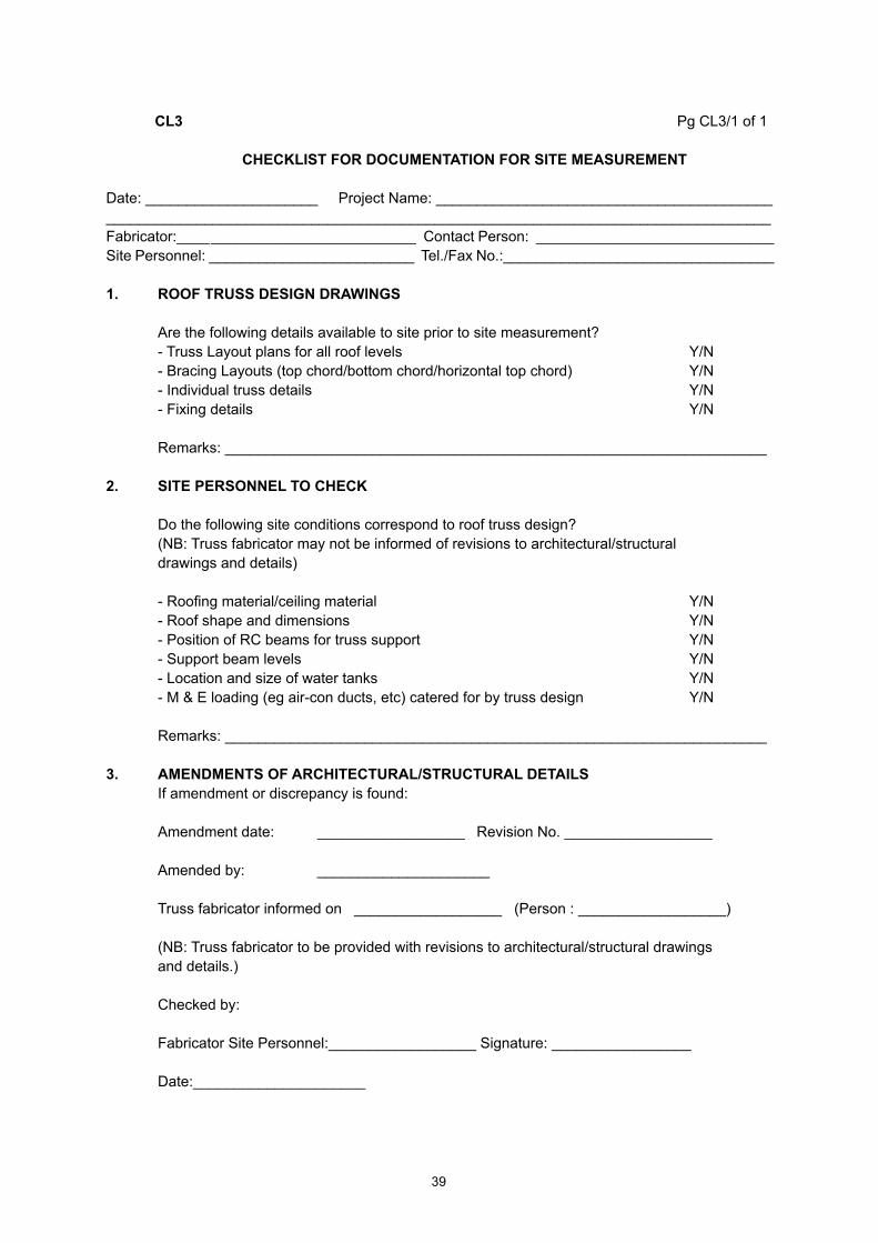
CHECKLISTFORDOCUMENTATIONFORSITEMEASUREMENT
Date: _____________________ Project Name: __________________________________________________________________________________________________________________________Fabricator:____ _________________________ Contact Person: _____________________________Site Personnel: _________________________ Tel./Fax No.:_________________________________
1. ROOFTRUSSDESIGNDRAWINGS
Are the following details available to site prior to site measurement? - Truss Layout plans for all roof levels Y/N - Bracing Layouts (top chord/bottom chord/horizontal top chord) Y/N - Individual truss details Y/N - Fixing details Y/N
Remarks: __________________________________________________________________
2. SITEPERSONNELTOCHECK
Do the following site conditions correspond to roof truss design? (NB: Truss fabricator may not be informed of revisions to architectural/structural drawings and details)
- Roofing material/ceiling material Y/N - Roof shape and dimensions Y/N - Position of RC beams for truss support Y/N - Support beam levels Y/N - Location and size of water tanks Y/N - M & E loading (eg air-con ducts, etc) catered for by truss design Y/N
Remarks: __________________________________________________________________
3. AMENDMENTSOFARCHITECTURAL/STRUCTURALDETAILS If amendment or discrepancy is found:
Amendment date: __________________ Revision No. __________________
Amended by: _____________________
Truss fabricator informed on __________________ (Person : __________________)
(NB: Truss fabricator to be provided with revisions to architectural/structural drawings and details.)
Checked by:
Fabricator Site Personnel:__________________ Signature: _________________ Date:_____________________

40
CL 4 Pg CL4/1 of 4
CHECKLISTFORTIMBERANDTRUSSESATTRUSSPLANT
Fabricator Name: _______________________________Factory Location: _______________________________ Tel: __________________________ _______________________________ Fax: __________________________
Project Title: ______________________________________________________________ ______________________________________________________________ ______________________________________________________________
Block Checked: ______________________ Job No.: _______________________
Factory Manager: ______________________
Quality Control Officer forTimber Selection & Sorting: _________________ Timber Sizing: _________________________Truss Assembly & Pressing: __________________ Timber Treatment: ______________________
Date of Inspection: _______________________
Fabricator’s Representative (Name & Signature):__________________________________________
A. RESULT OF TIMBER AND TRUSSES INSPECTION AT TRUSS PLANT
This inspection on timber, timber preservative treatment and truss fabrication at the truss plant was commenced on _________________ and were found to:
a) Conform to manufacturing specifications of the System Provider. Yes/No
If ‘No’,b) The findings and rectifications or actions required are:
1. ______________________________________________________
2. ______________________________________________________
Verified by MTIB: __________________ Company Stamp :
Signature: __________________________ Date: ___________________________

41
Pg CL4/2 of 4
Generalnote:This checklist is used to check trusses fabricated at a licensed fabricator’s truss plant.
1.0 TIMBERPRESERVATIVETREATMENT
Instructions:i) Ifcheckedparametercomplieswiththespecifications,mark‘3’.Otherwisemark‘X’ intheappropriateboxprovided.CommentstobenotedintheSection6.0‘REMARKS’ifappropriate.
1.1 Is timber treatment done within the plant?
1.2 If answer to above is ‘NO’. - Are treatment certificates provided by the supplier and done to specification? (Treatment Certificate) 1.3 If treatment is done within the plant. - Is treatment certificate provided by the fabricator and treatment done to specification? (Treatment Certificate)
GENERAL INSTRUCTIONS FOR SECTIONS 2.0, 3.0 AND 4.0:
i) Ten (10) trusses shall be randomly selected and individually checked against the truss design drawings(RefertoTrussDesignDrawings)fortheparametersstatedinSections2.0,3.0and 4.0 below.ii) UseseparatepageCL.4/4foreachindividualtrussselectedtorecordresultsforSection3.0 Truss Geometry and Section 4.0 Truss Quality Jointing Inspection checks.iii) Fornon-conformances,statetheactionorrectificationneeded.
2.0 TIMBERSIZE,GRADE,DEFECTSANDBOWINSPECTION
Instructions: 1.0 Foreachtruss,checkfordefectsintimberexceedingthelimitsstatedintheMS1714 intermsof‘Splits,Knots,Slopinggrain,Borerholes,Bowetc.” 2.0 Foreachtruss,randomlypickaminimumofonetimbercomponentforeachcross- section size and record its measurement.
2.1 What type of timber grading method used to grade timber?
Visual Grading Machine Grading
(Refer Attachment 3: Grading Summary) 2.2 Check on the selected timber component(s) of each individual truss selected for the criteria in the following table.

42
Pg CL4/3 of 4
Table1:MeasuredSizesandPresenceofDefects
NOTE: In the cross-section column states the various required nett design timber sizes for the selected trusses. Refer to Annex E and MS 1714 for defects identification
3.0 TRUSS GEOMETRY
Instructions: i) Foreachtruss,sketchtheoveralltrussprofileonPgCL4/4andchecktheoverall span and height against the fabrication drawings.
4.0 TRUSS JOINTING QUALITY INSPECTION
Instructions:i) Forbothfacesofeachjointforeachselectedtruss,recordtheconnectorsizes,positioning andjointingqualityinPgCL4/4of4.
4.1 Inspect jointing quality of finished truss.
5.0 MARKING&STACKINGOFFINISHEDTRUSSES
5.1 Are finished trusses clearly and correctly marked?
5.2 Stacking of finished trusses :
a) Are trusses bundled off the ground? (To avoid the trusses from being saturated specifically after raining)
b) Are trusses stacked correctly and supported sufficiently to avoid sagging?
6.0 REMARKS(ifany) ___________________________________________________________________________
___________________________________________________________________________
TRUSS DEFECTS REMARKS 1 2 3 4 5 6 7
CROSS-SECTIONSIZE(mmxmm)__x__ __x__ __x__ __x__

43
Pg CL4/4 of 4
General note: Use ONE sheet of this page for EACH truss checked.
ForSection3.0:TRUSSGEOMETRY
REMARKS: _________________________________________________________________ ______________________________________________________________________
ForSection4.0:TRUSSJOINTINGQUALITYINSPECTION(Check both faces of truss joints)
TRUSS PROFILE, MEMBER, AND JOINT NOS. DATATRUSS MARKTRUSS NO.CHORD NO.WEBS NO.PROJECT:
NO JOINTS PLATE PLATE PLATE TIMBER JOINT JOINT REMARKS NOS. SIZES PLACEMENT PRESSING THICKNESS TIGHTNESS TYPE 1 2 3 4 5 6 7 8 9 10 11 12 13 14 15 16 17 18 19 20

44
CL5. Pg CL5/1 of 8
CHECKLISTFORTRUSSINSTALLATION
Fabricator Name: ___________________________________________________________________
Project Title: _______________________________________________________________________ _______________________________________________________________________ _______________________________________________________________________Block Checked: ________________________Job No.: _____________________________________Installer: __________________________________________________________________________
The final inspection is carried out in the presence of:• System Provider: ______________________________________________________________• Fabricator: ______________________________________________________________• Professional Engineer: _____________________________________________________________• Main Contractor’s Rep ______________________________________________________________• Consultant Engineer or S.O. Reps/JKR: ________________________________________________Date of Inspection: ___________________
A. RESULT OF TRUSS INSTALLATION INSPECTION
If any remedial work needs to be carried out, the proposed rectification is:
1. _________________________________________________________________________
2. _________________________________________________________________________
3. _________________________________________________________________________
4. _________________________________________________________________________
Approved By P.E.(Name): _______________________ Company Stamp
Signature: __________________________ Date: _______________
1 Wallplates2 Trusses And Rafters3 Bracing Timber Bracing Steel Bracing4 Other Framing Components Waling Plate Under-Purlins5 Service Loads6 Tile Battening (if applicable)7 Purlins (if applicable) 8 Fascia Board
Materials MaterialsOK NOT OK OK NOT OK
Remarks

45
Pg CL5/2 of 8
GeneralInstructions:i) Usechecklistinconjunctionwithtrusslayoutandfullsetoftrussdesigns(RefertoDesign Drawings).ii) Wherebrackets[]areprovided,mark3ifacceptable,markXifrectificationisrequired.iii) Ontrusslayoutplan,identifylocationofdefectbyputtingacross“X”whereitoccurs,and describedefectbywritingitemnumber,e.g.1.2(c)meansstarterbarnotbentproperly.
1. WALL-PLATES (extra care for roofs subject to high wind loading) Specified size : _____________________ Grade specified : _____________________ No. Location Measured Non-permissible Remarks (orgridline) Size Defects(Y/N) 1 2 3
1.1 Materials: a) No non-permissible timber defect between starter bar and truss [ ] b) Size of starter bar/anchor bolt matches the specifications [ ]
1.2 Workmanship: a) Gaps between the wall plate and beam at truss/rafter positions packed [ ] b) No knots at starter bar/anchor bolt positions [ ] c) Anchor bars bent sharply and secured at the ends [ ] d) If applicable, washers provided for anchor bolts [ ] e) If applicable, anchor bolts tightened [ ] f) All wall plates anchored at a minimum of 2 locations, or wall-plate with one anchor joined to next piece with steel brace or timber block [ ] g) Wall-plate not notched for roofs subject to high wind loading [ ]
2. TRUSSES AND RAFTERS
2.1 Materials: a) Timber - defects within permissible limits* - i) Knots [ ] iii) Checks and shakes (splits) [ ] ii) Wane [ ] iv) Fractures [ ]
*RefertoMS544Part2orMalaysianGradingRulesforStandardStructuralorbetter grade
b) Truss joints- i) Damage to connectors [ ] ii) Missing connectors [ ]
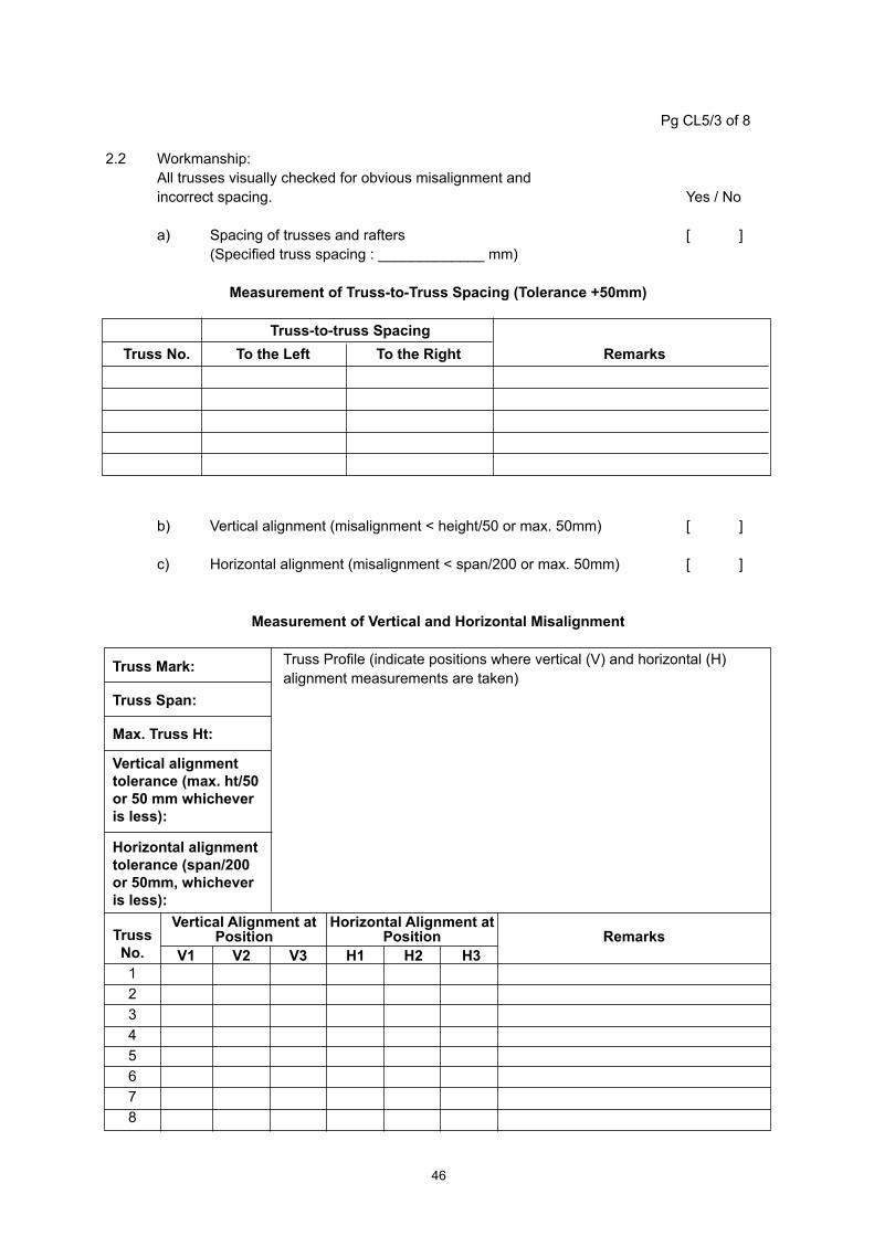
46
Pg CL5/3 of 8
2.2 Workmanship: All trusses visually checked for obvious misalignment and incorrect spacing. Yes / No a) Spacing of trusses and rafters [ ] (Specified truss spacing : _____________ mm)
MeasurementofTruss-to-TrussSpacing(Tolerance+50mm)
Truss-to-trussSpacing TrussNo. TotheLeft TotheRight Remarks
b) Vertical alignment (misalignment < height/50 or max. 50mm) [ ]
c) Horizontal alignment (misalignment < span/200 or max. 50mm) [ ]
MeasurementofVerticalandHorizontalMisalignment
TrussMark:
TrussSpan:
Max.TrussHt:
Verticalalignmenttolerance(max.ht/50or50mmwhicheverisless):
Horizontalalignmenttolerance(span/200or50mm,whicheverisless):
Truss Profile (indicate positions where vertical (V) and horizontal (H) alignment measurements are taken)
TrussNo.12345678
VerticalAlignmentatPosition
HorizontalAlignmentatPosition Remarks
V1 V2 V3 H1 H2 H3

47
Pg CL5/4 of 8
d) Internal supports provided at correct locations as designed [ ]
e) Gap between trusses and internal beams not used for support [ ]
f) Trusses spaced to allow location of service loads, e.g. water tank [ ]
g) Mid-web ties- i) Positioned at mid-web [ ] ii) Nailed at all junctions [ ] iii) Diagonals fixed at the correct angle [ ] iv) Diagonals nailed at all junctions [ ] MID-WEB TIE - MWT (Specified Sizes : _________________________)
No. Bracing MeasuredSize Non-permissible Remarks Type* Defects(Y/N)
1
2
3
4
5
6
7
8
9
10 * For abbreviations used for various bracing types, refer to Section 3 Bracing
h) Chord and web stiffeners i) Continuous length [ ] ii) Nailing centres to detail [ ] iii) Web stiffeners form T-sections [ ] i) Truss and rafter are anchoring to wallplate i) Type of connector [ ] ii) No. of connectors at each support [ ] iii) Are the connectors correctly installed (if applicable) [ ] iv) Nos. of nails driven in [ ] v) Nail type [ ] j) Truss to truss connection i) Trusses to girders as detailed [ ] ii) Saddles to trusses as detailed [ ] iii) Cap trusses to support trusses as detailed [ ] k) Rafters to truss fixing as detailed [ ]

48
Pg CL5/5 of 8
3. BRACING Specified Sizes : _______________________________________________
No. Bracing MeasuredSize Non-permissible Remarks Type* Defects(Y/N)
1
2
3
4
5
6
7
8 *Abbreviations used for bracing types : Top Chord Bracing - tcb Bottom Chord Tie - bct Bottom Chord Bracing - bcb Diagonal brace - db
3.1 Materials of correct size and type [ ]
3.2 Workmanship (timber bracing) a) Diagonal bracing provided for positional stability [ ] b) Bracing nailed at all junctions [ ] c) Bracing spliced according to specifications [ ] d) Bracing finished at wall plate according to specifications [ ] e) Bracing detail at cantilever [ ] f) Bracing angles [ ] g) Bracing lay-out [ ] h) For multilevel trusses, horizontal top chords of supporting trusses laterally tied and braced [ ]
3.3 Workmanship (steel brace) a) Bracing layout and position [ ] b) End fixing detail at heel [ ] c) End fixing at apex [ ] d) Bracing splicing detail [ ] e) Bracing tightness [ ] f) Nail type and size [ ]
4. OTHERFRAMINGCOMPONENTS 4.1 Walling plate a) Material [ ] b) Fixing detail [ ] 4.2 Under-purlins a) Material [ ] b) Fixing detail [ ]

49
Pg CL5/6 of 85. SERVICELOADS5.1 Type of service loads a) Water tanks [ ] b) Solar heaters [ ] c) Air-conditioning ducting [ ] d) Others - __________________ [ ]
5.2 Support structure for service loads if specified in truss drawing [ ]
6. TILEBATTENING(ifapplicable) Max. batten spacing : _________________ Specified size : _______________________ Grade specified :_____________________
No. Measured Spacing+ Non-permissible Remarks Size Defects(Y/N)
1
2
3
4
5 NOTE: + As measured from the centre of the batten to the centre of the next batten up the slope
6.1 Material of correct size and type [ ]
6.2 Workmanship a) Spacing of batten for eave tile according to Client’s/Manufacturer’s details [ ] b) For trusses without fascia board, eaves batten are higher [ ] b) Spacing of intermediate battens according to Client’s/Manufacturer’s details [ ] d) Spacing of top batten for ridge tile according to Client’s/Manufacturer’s details [ ] e) All battens nailed at junctions [ ] f) Battens for metal tiles fixed with batten anchors in high buildings [ ] g) Battening is continuous at saddle truss areas [ ]

50
Pg CL5/7 of 8
7. PURLINS(ifapplicable)
Max. purlin spacing : _________________ Specified size : ____________________ Grade specified : __________________
No. Measured Spacing+ Non-permissible Remarks Size Defects(Y/N)
1
2
3
4
5 NOTE: + As measured from the centre of the purlin to the centre of the next purlin up the slope
7.1 Material of correct size and type [ ]
7.2 Workmanship a) Top purlin spaced to suit fixing of ridge piece [ ] b) Intermediate purlins spaced- i) Within Manufacturer’s limit [ ] ii) To suit multiple sheets [ ] iii) To allow for end laps of multiple sheets [ ] c) Purlins fixed with purlin anchors according to detail [ ] d) Orientation of purlins according to design detail [ ]
8. TIMBER FASCIA BOARD Specified size (by fabricator) : _____________________
No. Location MeasuredSize Non-permissible Remarks (orgridline) Defects(Y/N)
8.1 Material of correct size and type [ ] 8.2 Workmanship a) For concrete/clay tile roofs, fascia board positioned above batten line for eaves tile [ ] b) Fascia board spliced at the correct positions [ ] c) Horizontal alignment of fascia board [ ] d) Edge of eaves tile is in line with axis of storm gutter [ ]

51
Pg CL 5/8 of 8
9. SKETCHES(note any damage caused by other sub-contractors):
I. II.
III. IV.

52
ANNEX E(normative)
MS 544: PART 2: 2001 CODE OF PRACTICE FOR STRUCTURAL USE OF TIMBERPART 2 : PERMISSIBLE STRESS DESIGN OF SOLID TIMBER
AppendixC.GradingofMalaysianstructuraltimbers

53
AppendixE
GRADING OF MALAYSIAN STRUCTURAL TIMBERS
E1. Grade
The timber should be graded, by assessing the characteristics covered by Clauses E1 to E11 inclusive on each piece, in the size and condition in which it is used, in the following grades:
a) select structural;
b) standard structural; and
c) common building
The grades are multipurpose grades, i.e. applicable to all structural timbers whether used as bending members, or in endwise compression. In the case of timber used as beams, the recommended working stresses (as given in Clause 6 Design considerations of MS 544 : Part 1) will apply no matter which way up the members intended for resawing to shorter lengths.
The standard structural grade should be specified for normal purposes.
The select structural grade is intended for special purposes, particularly when the strength/weight ratio of the timber is to be a maximum, for example in towers for transmission lines and trusses of very long span.
The common building grade is intended for wooden members used in less important parts of building frames, which are not usually designed by means of engineering calculations.
E2. OPENSHAKES,SURFACECHECKSANDENDCHECKS
E2.1 Measurement
The size of an open shake or surface check should be taken as its depth projected onto a surface at right angles to the face on which it occurs. The projected depths of all checks occurring within the middle half of the face should be added together to assess the magnitude of the total defect.
A feeler gauge of 0.13 mm thickness should be used in measuring the size of an open shake or surface check.
E2.2 Grading limits
To qualify for a particular grade, a member should not have shaken or checks whose size, expressed as a fraction of the width of the face at right angles to the one on which the defects occur, exceeds the maximum value given in Table E1.

54
TableE1.MaximumSizeofShakesandChecks
Grade MaximumPermissibleLimit
Select 1/6 thickness
Standard 1/3 thickness
Common 1/2 thickness
E3. Slope of Grain
E3.1 Measurement
The slope of grain should be measured over a distance sufficiently great to determine the general slope, disregarding slight local deviations (round small knots, etc.). The minimum distance over which the slope of grain is measured should not ordinarily be less than the distance over which a deviation of 25 mm is permitted, e.g. a slope of 1 in 15 should be measured over a distance of not less than 375mm if possible. A cranked scribe with a freely swiveling handle should be used. The slope of grain shall be measured on the face or edge where it is most severe (see E12).
E3.2 Grading limits
To qualify for a particular grade, a member should not have a slope of grain steeper than the value given in Table E2.
TableE2.MaximumSlopeofGrain
Grade MaximumSlopeofGrain
Select 1 in 16 Standard 1 in 10.7 Common 1 in 8
E4. Spiral Grain
Where spiral grain occurs, the slope of grain should be determined by measuring the worst slope of grain on the faces and edges and taking the square root of the sum of the square of the slopes. For example if these slopes are 1 in 18 and 1 in 12, the combined slope is:
or a slope of 1 in 10
NOTE:This procedure is intended to apply where it is deemed necessary to measure the slope of grain in most cases, it will be sufficient for the grader to use his judgement in rejecting timber containing spiral grain to an undesirable extent.
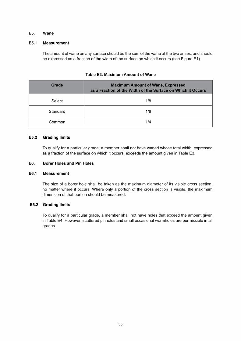
55
E5. Wane
E5.1 Measurement
The amount of wane on any surface should be the sum of the wane at the two arises, and should be expressed as a fraction of the width of the surface on which it occurs (see Figure E1).
TableE3.MaximumAmountofWane
Grade MaximumAmountofWane,Expressed asaFractionoftheWidthoftheSurfaceonWhichItOccurs Select 1/8
Standard 1/6
Common 1/4
E5.2 Grading limits
To qualify for a particular grade, a member shall not have waned whose total width, expressed as a fraction of the surface on which it occurs, exceeds the amount given in Table E3.
E6. BorerHolesandPinHoles
E6.1 Measurement
The size of a borer hole shall be taken as the maximum diameter of its visible cross section, no matter where it occurs. Where only a portion of the cross section is visible, the maximum dimension of that portion should be measured.
E6.2 Grading limits
To qualify for a particular grade, a member shall not have holes that exceed the amount given in Table E4. However, scattered pinholes and small occasional wormholes are permissible in all grades.

56
Amount of wane on the face of the member to be specified by the ratio:
Amount of wane on the edge of the member to be specified by the ratio:
TableE4.MaximumAmountofPin,ShotandBorerHoles
Pin<1.6mm Shot(1.6–3.2mm) Borer(3.2to6.4mm)
Select 16 in 100cm2 2 per 900cm2 None
Standard 32 in 100cm2 4 per 900cm2 2 per 900cm2
Common Unlimited 8 per 900cm2 4 per 900cm2
E7. Sapwood
Sapwood, though not a structural defect, is liable to attack by fungi and termites if not treated, whether or not the timber is a naturally durable species. Therefore, where durability is the main consideration, the timber with sapwood, even of a naturally durable specifies, should be treated. If not, the sapwood shall be limited so as not to exceed the amount given in Table E3, expressed as a fraction of the width of the surface on which it occurs.
MaximumAmountofHolesGrade
FigureE1.ExtentofWane
v1 d or v2 + v3
d K1 b or K2 + K3
b

57
FigureE2.ExtendofSapwood
E8. Stain
Stain, provided the timber is free from decay, is not a structural defect and shall be acceptable.
E9. Curvature
E9.1 Measurement
The extent of curvature is determined by measuring the maximum deviation from a tightly stretched string or wire, expressed as a ratio of the length of the timber.
E9.2 Grading limits
To qualify for a particular grade, a member shall not have curvature whose deviation exceeds the amount given in Table E5.
TableE5.MaximumAmountofCurvature
Grade Maximum Slope of Grain Select 5 mm in 3 m Standard 10 mm in 3 m Common 15 mm in 3 m
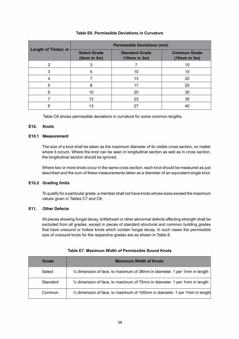
58
PermissibleDeviations(mm)LengthofTimber,m
TableE6.PermissibleDeviationsinCurvature
SelectGrade StandardGrade CommonGrade (5mmin3m) (10mmin3m) (10mmin3m) 2 3 7 10
3 5 10 15
4 7 13 20
5 8 17 25
6 10 20 30
7 12 23 35
8 13 27 40
Table C6 shows permissible deviations in curvature for some common lengths.
E10. Knots
E10.1 Measurement
The size of a knot shall be taken as the maximum diameter of its visible cross section, no matter where it occurs. Where the knot can be seen in longitudinal section as well as in cross section, the longitudinal section should be ignored.
Where two or more knots occur in the same cross section, each knot should be measured as just described and the sum of these measurements taken as a diameter of an equivalent single knot.
E10.2 Grading limits
To qualify for a particular grade, a member shall not have knots whose sizes exceed the maximum values given in Tables C7 and C8.
E11. OtherDefects
All pieces showing fungal decay, brittleheart or other abnormal defects affecting strength shall be excluded from all grades, except in pieces of standard structural and common building grades that have unsound or hollow knots which contain fungal decay. In such cases the permissible size of unsound knots for the respective grades are as shown in Table 8.
TableE7.MaximumWidthofPermissibleSoundKnots
Grade MaximumWidthofKnots
Select ⅛ dimension of face, to maximum of 38mm in diameter. 1 per 1mm in length
Standard ¼ dimension of face, to maximum of 75mm in diameter. 1 per 1mm in length
Common ⅓ dimension of face, to maximum of 100mm in diameter. 1 per 1mm in length

59
TableE8.MaximumWidthofPermissibleUnsoundKnots
Grade Maximumwidthofknots
Select None
Standard dimension of face, to maximum of 50mm in diameter. 1 per 2.4mm in length
Common ¼ dimension of face, to maximum of 75mm in diameter. 1 per 1mm in length
E12. Guided to the Determination of Slope of Grain
To ascertain the slope of the grain in timber it is necessary to study both the quartered and flat-sawn faces of the member.
If seasoning checks are present, these will indicate the slope of the grain.
Slope of grain can be more accurately determined by means of a scribe, as shown in Figure E3 comprising a cranked rod with a swivel handle and a needle, similar to a gramophone needle, at the tip, set ata slight trailing angle. The needle is pressed into the wood and the scribe is drawn along with a steady action in the apparent dissection of the grain, which is indicated more precisely as the needle forms a groove. If the pressure on the needles is insufficient, it may be dragged across the grain: on the other hand, a steady action is impossible if the pressure is excessive and the needle penetrates too far into the wood.
If the action is correcting the needle follows the grain even when the direction of pull of the scribe is slightly out of line. This may be used to check that the scribe does follow the grain by scribing another groove in close proximity on each side of the original one with the direction of pull diverging slightly outwards in each case when, if the grooves are following the grain, they will be parallel to each other.
The inclination of grain on a face is measured as shown in Figures E4 and E5, in which AB is the line indicating grain direction, AC is a line drawn parallel to the edge of the member, BC is of length one unit (any convenient unit may be used) and is at right angles to AC. Grain inclination is expressed as ‘one in x’ where x is the length of AC measured in terms of BC.
The slope of grain should be measured on two adjacent faces, and from the values obtained the true inclination of the grains to the longitudinal axis of the member should be determined in accordance with E4.

60
FigureE3.Swivel-handedScriberfortheDeterminationofSlopeofGrainintheWood
FigureE4.UseofScriber
FigureE5.MeasurementofSlopeGrain

61
ANNEX F(normative)
MS544:1978TABLEA1.CLASSIFICATIONOFTIMBERSINTOSHRINKAGEGROUPS
TableA1.ClassificationofTimbersintoShrinkageGroups
(based on average tangential shrinkage from green to 19% moisture content)
Group 10.5–1.5%inclusive
CHENGAL*(Balanocarpusheimi - King)
DAMAR MINYAK*(Agathis alba)
JELUTONG*(Dyer a costulata -Hook. f.)
KELEDANG*(Artocarpuslanceifolius - Roxb.(A.rigidus)
KUNGKUR*(Pithecellobiumconfertum)
MACHANG*(Mangifera longipes)(M. indica)(M. foetidaLour.)
Group 2Over1.5–2.5%
BINTANGOR*(Calopylluminophyllum)(C.kunstleri)(C.curtisii)
GIAM*(Hopea helferi(Dyer, Brandis)(H. nutans - Ridl.)
KERANJI*(DialiumPlatysepalum
Baker)MEDANG*(Litsea megacapa)(L. firma)
MEMPISANG*(Cathocalyxmaingayi)
MERANTI, DARK RED*(ShoreabracteolataDyer)
Group 3Over2.5–3.5%
BALAU*(Shorea laevisRidl.)(S. maxwellianaKing)(S. glauca - King)
BALAU, RED*(Shorea guiso(Blanco) Bl.)(S. kunstleri - King)(S. ochroploia)
BITIS*(Madhuca utilisRidl.)(H.J. Lam)
DURIAN*(Duriooxleyanus)
KEDONGONG*(Canarium rufum)(Santirialaevigata - Bl.)
KEKATONG*(CynometrainaequifoliaA. Gray)
Group 4Over3.5–5%
GERONGGANG*(Cratoxylon spp.)
KAPUR*(Dryobalanopsaromatica - Gaertn.)(D. oblongifolia)
KERUING*(Dipterocarpusbaudii - Korth)(D. cornutusDyer)(D. costulatusvan sloot)(D. crinitus)(D. lowii)
MEMPENING(Quercuslamponga))
MEMPISANG*(MezzittialeptopodaOliv.)
MERANTI, DARKRED*(Shoreaplatyclados)
Group 5Over5%
KERUING*(DipterocarpusGramdoflorus)
MERANTI BAKAU*(Shorea rugosavar. uliginosa)
PUNAH*(Tetrameristaglabra)
*Timbers that appear in the Malaysian Grading Rules

62
TableA1.Continued
Group 10.5–1.5%inclusive
MEDANG*(Dehaasianigrescens)
MERANTI, WHITE*(Shorea talura)
MERBAU*(IntsiapalembanicaBaker) MERPAUH*(Swintoniaschwenkii)(S. spiciferaHook.f.)(S.penangiana) RENGAS*(Melanorrhoeatorquota)
SEPETIR*(SindoracoriaceaPrain) SESENDOK*(EndospermummalaccenseMuell. -Arg.) TUALANG*(Koompassiaexcelsa - Taub.)
Group 2Over1.5–2.5%
MERANTI, LIGHTRED*(ShoreahemsleyanaKing) MERANTI, WHITE*(Shorea bracteolataDyer)
MERAWAN*(Hopea sulcata) PERUPOK*(Lophopetalumreflexum)(L. MaingayiRidl.)(L. floribundum)(L. subovatumKing) PULAI*(Alstoniaangustiloba) TABAN MERAH(Palaquinumgutta) TEMBUSU*(FragraeaFragransRoxb.)
Group 3Over2.5–3.5%
KEMPAS*(KoompassiamalaccensisMaing.)
KULIM*(Scorodocarpusborneersis - Becc.)MELUNAK*(Pentacetriptera - Mast) MENGKULANG*(Heritierajavanica Bl.)(H. simplicifolia Mast.)
MERANTI, DARK RED*(Shorea pauciflora King) MERANTI, WHITE*(Shorea hypochraHance) MERANTI, YELLOW*(Shorea resinanigra Foxw.) MERAWAN*(Hopea nervosa King) MERTAS(Ctenolophon parvifolius) MINYAK BEROK(Xanthophyllumverrucosum) PENARAHAN*(Myristica gigantea)(M.maingayi) PENAGA(Mesua ferrea) RAMIN (MELAWIS)*(Gonystylusbancanus (Miq.) Baill.) RESAK*(Vatica cuspidata(Ridl.) Sym.) TERAP*(ArtocarpusScortechnii Hook.f.) TERENTANG*(CampuospermaAuriculata Hook.f.)
Group 4Over3.5–5%
MERANTI, LIGHTRED*(Shoreaparvifolia Dyer) MERANTI, LIGHTRED*(Shorealeprosula Miq.)(Shoreaacuminata - Dyer) MERSAWA*(Anisoptera spp.)
NYALAS*(Parastemonurophyllum) SIMPOH*(Dilleniagrandifolia) TERAP*(Parartocarpustriandra) TERENTANG*(CampnospermaMacrophylla)
Group 5Over5%
*Timbers that appear in the Malayan Grading Rules

63
ANNEX G (informative)
TERMS APPLYING TO PREFABRICATED TIMBER ROOF TRUSSES
FigureG1.TermsApplyingtoPrefabricatedTimberTrusses
FigureG2.TermsApplyingtoRoofTrussSystem

64
ANNEXH (informative)
SomeExamplesofTrussFabricationDefectsInvolvingtheToothedMetalPlate(NailPlate)Connectors
Termsappliedtoarooftrusssystem
a)
b)
c)

65
74
Figure H1. Toothed metal plate connectors
a) Gap between the underside of connector to the timber surface
b) embedment of the connector plate into the timber
Figure H2. Embedment of connector plate
a) Proper positioning of connector plate
Side view of nail plate at butt joint
Side view of nail plate at butt joint
Top view of nail plate at butt joint
1.5 mm or less
0.5 mm or less
Nail plate
Nail plate0.5 mm or less
FigureH1.ToothedMetalPlateConnectors
a) Gap between the underside of connector to the timber surface
74
Figure H1. Toothed metal plate connectors
a) Gap between the underside of connector to the timber surface
b) embedment of the connector plate into the timber
Figure H2. Embedment of connector plate
a) Proper positioning of connector plate
Side view of nail plate at butt joint
Side view of nail plate at butt joint
Top view of nail plate at butt joint
1.5 mm or less
0.5 mm or less
Nail plate
Nail plate0.5 mm or less
b) Embedment of the connector plate into the timber
74
Figure H1. Toothed metal plate connectors
a) Gap between the underside of connector to the timber surface
b) embedment of the connector plate into the timber
Figure H2. Embedment of connector plate
a) Proper positioning of connector plate
Side view of nail plate at butt joint
Side view of nail plate at butt joint
Top view of nail plate at butt joint
1.5 mm or less
0.5 mm or less
Nail plate
Nail plate0.5 mm or less
FigureH2.EmbedmentofConnectorPlate
a) Proper positioning of connector plate

66
75
b) Mispositioning of connector plate across the width of timber
c) Mispositioning of connector plate along the length of timber
Note: Mispositioning of connector by not more than 6mm for connector dimension of less than 150mm (in the direction of the dimension), and, 12mm for connector dimension of 150mm or more (in the direction of the dimension).
Figure H3. Positioning of toothed metal plate connectors.
Figure H4. Side view of a butt joint: acceptable placement of nail plates(teeth are not bent or flattened)
Top view of nail plate at butt joint
Top view of nail plate at butt joint
Part of connector projects outside the timber edge
Misposition
Misposition
Side view of nail plates at butt joint
Nail plate
b) Mispositioning of connector plate across the width of timber
75
b) Mispositioning of connector plate across the width of timber
c) Mispositioning of connector plate along the length of timber
Note: Mispositioning of connector by not more than 6mm for connector dimension of less than 150mm (in the direction of the dimension), and, 12mm for connector dimension of 150mm or more (in the direction of the dimension).
Figure H3. Positioning of toothed metal plate connectors.
Figure H4. Side view of a butt joint: acceptable placement of nail plates(teeth are not bent or flattened)
Top view of nail plate at butt joint
Top view of nail plate at butt joint
Part of connector projects outside the timber edge
Misposition
Misposition
Side view of nail plates at butt joint
Nail plate
c) Mispositioning of connector plate along the length of timber
FigureH3.PositioningofToothedMetalPlateConnectors
NOTE: Mispositioning of connector by not more than 6mm for connector dimension of less than 150mm (in the direction of the dimension), and, 12mm for connector dimension of 150mm or more (in the direction of the dimension).
75
b) Mispositioning of connector plate across the width of timber
c) Mispositioning of connector plate along the length of timber
Note: Mispositioning of connector by not more than 6mm for connector dimension of less than 150mm (in the direction of the dimension), and, 12mm for connector dimension of 150mm or more (in the direction of the dimension).
Figure H3. Positioning of toothed metal plate connectors.
Figure H4. Side view of a butt joint: acceptable placement of nail plates(teeth are not bent or flattened)
Top view of nail plate at butt joint
Top view of nail plate at butt joint
Part of connector projects outside the timber edge
Misposition
Misposition
Side view of nail plates at butt joint
Nail plate
FigureH4.SideViewofaButtJoint:AcceptablePlacementofNailPlates(teetharenotbentorflattened)

67
76
(a)
(b)
Figure H5. Side view of a butt joint: Teeth roll or roll-over (teeth bent or flattened)
a) Case 1
b) Case 2
Figure H6. Vertical gaps.
Nail plate moves during pressing
Nail plate moves during pressing
High density timber Very high density timber
Side view of nail plates at butt joint
Side view of the nail plates at butt joint
Top view of the nail plate at butt joint
Gap
Gap
Nail plate
Nail plate with teeth either bent or flattened
Side view of the nail plates at butt joint
Gap
(a)
76
(a)
(b)
Figure H5. Side view of a butt joint: Teeth roll or roll-over (teeth bent or flattened)
a) Case 1
b) Case 2
Figure H6. Vertical gaps.
Nail plate moves during pressing
Nail plate moves during pressing
High density timber Very high density timber
Side view of nail plates at butt joint
Side view of the nail plates at butt joint
Top view of the nail plate at butt joint
Gap
Gap
Nail plate
Nail plate with teeth either bent or flattened
Side view of the nail plates at butt joint
Gap
(b)
FigureH5.SideViewofaButtJoint:TeethRollorRoll-over(teethbentorflattened)
76
(a)
(b)
Figure H5. Side view of a butt joint: Teeth roll or roll-over (teeth bent or flattened)
a) Case 1
b) Case 2
Figure H6. Vertical gaps.
Nail plate moves during pressing
Nail plate moves during pressing
High density timber Very high density timber
Side view of nail plates at butt joint
Side view of the nail plates at butt joint
Top view of the nail plate at butt joint
Gap
Gap
Nail plate
Nail plate with teeth either bent or flattened
Side view of the nail plates at butt joint
Gap
a) Case 1
76
(a)
(b)
Figure H5. Side view of a butt joint: Teeth roll or roll-over (teeth bent or flattened)
a) Case 1
b) Case 2
Figure H6. Vertical gaps.
Nail plate moves during pressing
Nail plate moves during pressing
High density timber Very high density timber
Side view of nail plates at butt joint
Side view of the nail plates at butt joint
Top view of the nail plate at butt joint
Gap
Gap
Nail plate
Nail plate with teeth either bent or flattened
Side view of the nail plates at butt joint
Gap
FigureH6.VerticalGaps

68
77
Figure H7. Horizontal gap in built-up structural members
a) Case 1
b) Case 2
Figure H8. Mismatch timbers
Side view of the nail plates at butt joint
Side view of the nail plates at butt joint
Edge joint
End joint
Gap
Top view of nail plates at the edgeand end jointed components
Nail platxe
FigureH7.HorizontalGapinBuilt-upStructuralMembers
77
Figure H7. Horizontal gap in built-up structural members
a) Case 1
b) Case 2
Figure H8. Mismatch timbers
Side view of the nail plates at butt joint
Side view of the nail plates at butt joint
Edge joint
End joint
Gap
Top view of nail plates at the edgeand end jointed components
Nail platxe
a) Case 1
77
Figure H7. Horizontal gap in built-up structural members
a) Case 1
b) Case 2
Figure H8. Mismatch timbers
Side view of the nail plates at butt joint
Side view of the nail plates at butt joint
Edge joint
End joint
Gap
Top view of nail plates at the edgeand end jointed components
Nail platxe
b) Case 2
Thickness mismatch
Thickness mismatch
FigureH8.MismatchTimbers

69
REFERENCES
Standards Australia International Ltd. AS 4440-2004 Installation of Nailplated Timber Roof Trusses. Sydney: Standard Australia International Ltd.; 2004.
European Committee for Standardization. BS EN 1991-1-1:2002 Eurocode 1. Action on Structure. General Actions. Densities, Self-weight Imposed Loads for Buildings. Brussels; 2002.
BS EN 1991-1-7:2006+A1:2014 Eurocode 1. Actions on Structure. General Actions. Accidental Actions. Brussles; 2006.

70
AKNOWLEDGMENT
This Malaysian Construction Industry Standard is a revision of the CIS 5:2004. The committee involved in the revision consists of the following representatives:
Tn. Hj. Sazali Che Amat Construction Industry Development Board MalaysiaNur Hanis AmsariRashimah AdenanAhmad Nuhairi Haji Abdul RazakZulkefli IsmailRamlan BidinMd Zahari Abdul Rahman
Ir. Pof. Dr. Mohd Zamin Bin Jumaat Board of Engineers Malaysia
Datin Salamah Selamat Forest Research Institute Malaysia
Zainuddin Mohd Damin Haustek Engineering Sdn. Bhd.
Tn. Hj. Ahmad Rosli Abd Rahman Jabatan Kerja RayaMegat Kamarulzaman Megat YusoffMohd Khairi Yaacob
Dr. Mohd Norzamri Mat Amin Malaysian Timber Industry BoardDr. Yeoh Beng HoongHajah Mahsuri Mat DrisNor Liza Mat YasokWan Suhaimi Wan Chek
Ng Wun Pin Multinail Asia Sdn Bhd
Ahmad Zabidi Abdul Rashid Persatuan Pengusaha Kayu-Kayan dan Perabot Bumiputra Malaysia
Ar. Mariyah binti Pit Pertubuhan Akitek Malaysia
Prof. Dr. Badorul Hisham Abu Bakar Universiti Sains MalaysiaDr. Mustafasanie M. Yussof
Prof. Madya Dr. Mohd Ariff Jamaludin Universiti Teknologi Mara (Chairman)
