quality assurance guidance document - us epa · foreword this document describes detailed standard...
TRANSCRIPT

United States Environmental Protection Agency
Office of Air Quality Planning and Standards Research Triangle Park,
September 2006
NC 27711 Air
Quality Assurance Guidance Document
Method Compendium
Field Standard Operating Procedures for the PM2.5 Performance Evaluation Program

[This page intentionally left blank.]
ii
Foreword
This document describes detailed standard operating procedures (SOPs) for the field activities of the PM2.5 Federal Reference Method (FRM) Performance Evaluation Program (PEP). It is the second major revision of this material and can be identified by the September 2006 distribution date. The original was developed in 1998 and the first major revision was issued in 2002.
The document was originally developed with the assistance of the various workgroups that are responsible for implementing or overseeing the field aspects of the PEP, including state and local organizations that have a vested interest in the quality of routine ambient air monitoring data. The personnel involved in these workgroups are listed in the acknowledgments. As the program has matured both field scientists and lab support personnel with operational experience have suggested several refinements to the myriad of procedures. The strengths and limitations of the samplers and instruments are well known and we now know which maintenance and repair issues to engage, or refer to the manufacturers. Finally we have attempted in this revision to put the field and laboratory operations in a logical temporal pattern that is easier for a new field scientist or lab technician to follow.
This document is accessible as a PDF file on the Internet on the Ambient Monitoring Technology Information Center (AMTIC) Bulletin Board under the quality assurance (QA) area of the PM2.5 Monitoring Information (http://www.epa.gov/ttn/amtic/amticpm.html). The document can be read and printed using Adobe Acrobat™ Reader software, which is freeware available from many Internet sites, including the U.S. Environmental Protection Agency (EPA) Web site. The Internet version is write-protected. Hardcopy versions are available by writing or calling:
Dennis Crumpler Office of Air Quality Planning and Standards MQAG (D205-02) Research Triangle Park, NC 27711 (919-541- 0871) Email: [email protected]
This is a living document, which means it may undergo revision as program objectives and implementation procedures evolve. Comments on technical content and presentation of this document may be sent to Dennis Crumpler. EPA Regional Contract Officer Representatives, Field Scientists, and laboratory technicians will use a process described herein. If serious errors are identified, they will be corrected immediately with a Quality Assurance Bulletin. Less dramatic evolutionary changes will be made through a revision cycle that usually concludes in the fall of each year.
The document mentions trade names or brand names. Mention of corporation names, trade names, or commercial products does not constitute endorsement or recommendation for use.
iii

[This page intentionally left blank.]
iv

FRM PEP Field SOP September 2006
Acknowledgments This compendium of field standard operating procedures (SOPs) is the product of the combined efforts of the U.S. Environmental Protection Agency (EPA) Office of Air Quality Planning and Standards (OAQPS); the Office of Radiation and Indoor Air support laboratories in Las Vegas, NV, and the EPA ORIA National Exposure Research Laboratory (NERL) Montgomery, AL; the EPA Regional Offices, State and local organizations, and subsequent field scientists and laboratory technicians who perform the day-to-day operations. The 2006 update was led and directed by Dennis Crumpler, Office of Air Quality Planning and Standards. The work was done under EPA Contract 68-D-02-065 by RTI International. The review of the material found in this document was accomplished through the activities of the PM2.5 QA Workgroup. The following individuals are acknowledged for their contributions: EPA Regions Region 1 Norman Beloin, Mary Jane Cuzzupe, Tony Palermo 2 Mark Winter, Yolonda Guess 3 Andrew Hass, Cathleen Kennedy 4 Greg Noah, Mike Birch 5 Scott Hamilton, Gordon Jones, Basim Dihu 6 John Lay, Melvin Ritter 7 Thien Bui, James Regehr 8 Michael Copeland, Kenneth Distler 9 Matt Plate, Rose Fong 10 Christopher Hall Research Triangle Institute Jennifer Lloyd, Emaly Simone, Ed Rickman, Jeff Nichol Office of Air Quality Planning and Standards Dennis Crumpler, Mike Papp, Office of Radiation and Indoor Air Jeff Lantz ESAT Field Scientists under contract to EPA in Regions 1 – 10 for the Fiscal Year 2006
v

FRM PEP Field SOP September 2006
Acknowledgments for the April 2002 Version The following individuals are acknowledged for their contributions to the first edition of the SOP (April 2002 version), which served as the basis for this 2006 method compendium: State and Local Organizations George Apgar, State of Vermont, Waterbury, VT Randy Dillard, Jefferson County Department of Health, Birmingham AL Kevin Goohs, Gordon Pierce, and Pat McGraw, CO Dept. of Public Health & Environment, Denver, CO Alice Westerinen, Russell Grace, and Tom Pomales, California Air Resources Board, Sacramento, CA Jeff Miller, Pennsylvania Department of Environmental Protection, Harrisburg, PA Richard Heffern, State of Alaska Department of Environmental Conservation, Juneau, AK Dan Harman, North Dakota Department of Health, Bismarck, ND Dave Wallenberg, STAPPA/ALAPCO EPA Regions Region 1 Norman Beloin, Mary Jane Cuzzupe, Tony Palermo 2 Clinton Cusick, Dick Coleates 3 Victor Guide, Theodore Erdman, Fred Foreman 4 Jerry Burger, Herb Barden, Mike Birch 5 Mary Ann Suero, Gordon Jones, Mike Rizzo, Basim Dihu, Jay Thakkar 6 Mary Kemp, Mark Sather, Kuenja Chung, Timothy Dawson, Ruth Tatom, Melvin Ritter 7 Leland Grooms, Mike Davis, Shane Munsch, Harold Brown 8 Ron Heavner, Gordan MacRae, Joe Delwiche, Barbara Daboll 9 Mathew Plate, Manny Aquitania, Bob Pallarino, Rose Fong 10 Barry Towns, Karen Marasigan, Bill Puckett, Gerald Dodo National Exposure Research Laboratory Frank McElroy, David Gemmill ESAT Organization Monica McEaddy, Kathleen Engel, Angela Edwards, Colleen Walling, Sam Jamison Research Triangle Institute James B. Flanagan, Cary Eaton, Robert Wright, Steve O’Brien Office of Air Quality Planning and Standards Mike Papp, Tim Hanley, David Musick
vi

FRM PEP Field SOP September 2006
Contents
Section SOP
Number Page Revision Date
Foreword iii Acknowledgments v Contents vii Tables and Figures ix Acronyms and Abbreviations x
Introduction xiii 2 9/06
1 Overview of FRM Performance Evaluation Field Activities
PEPF-1 1-1 2 9/06
2 Planning and Preparing for PEP Sampling Events PEPF-2 2-1 2 9/06 Equipment Inventory and Storage Communications Preparation for PEP Sampling Events
2-3 2-15 2-23
3 Cassette Receipt, Storage, and Handling PEPF-3 3-1 2 9/06
4 Sampler Transport and Placement PEPF-4 4-1 2 9/06
5 Sampler Setup and Performance Verifications PEPF-5 5-1 2 9/06 Sampler Assembly
Leak Check Procedures Flow Rate Verification Barometric Pressure Verification Temperature Verification Preparing to Sample
5-4 5-16 5-21 5-25 5-28 5-31
6 Filter Exposure and Concluding the Sampling Event PEPF-6 6-1 2 9/06 Conducting the Filter Exposure Sample Recovery and Data Download Filter Packing and Shipment Sampler Disassembly Sampler Maintenance and Cleaning
6-3 6-13 6-20 6-23 6-25
7 Chain of Custody and Field Data Sheet PEPF-7 7-1 2 9/06
8 Quality Assurance/Quality Control PEPF-8 8-1 2 9/06 Field Data Verification/Validation 8-9
9 Information Retention PEPF-9 9-1 2 9/06
10 Multipoint Verifications and Calibrations PEPF-10 10-1 2 9/06 Barometric Pressure Multipoint
Verification/Calibration Temperature Multipoint Verification/Calibration
10-3
10-10
vii

FRM PEP Field SOP September 2006
Section SOP
Number Page Revision Date Appendices A Glossary A-1 2 9/06 B Data Qualifiers/Flags B-1 1 11/98 C Data Forms C-1 2 9/06 D ESAT Contracts D-1 2 9/06 E Alternate Verification Devices E-1 1 9/06
viii
FRM PEP Field SOP September 2006
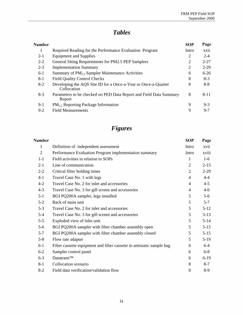
Tables
Number SOP Page 1 Required Reading for the Performance Evaluation Program Intro xxii
2-1 Equipment and Supplies 2 2-4 2-2 General Siting Requirements for PM2.5 PEP Samplers 2 2-27 2-3 Implementation Summary 2 2-29 6-1 Summary of PM2.5 Sampler Maintenance Activities 6 6-26 8-1 Field Quality Control Checks 8 8-3 8-2 Developing the AQS Site ID for a Once-a-Year or Once-a-Quarter
Collocation 8 8-8
8-3 Parameters to be checked on PED Data Report and Field Data Summary Report
8 8-11
9-1 PM2.5 Reporting Package Information 9 9-3 9-2 Field Measurements 9 9-7
Figures
Number SOP Page 1 Definition of independent assessment Intro xvii 2 Performance Evaluation Program implementation summary Intro xviii
1-1 Field activities in relation to SOPs 1 1-6 2-1 Line of communication 2 2-15 2-2 Critical filter holding times 2 2-29 4-1 Travel Case No. 1 with legs 4 4-4 4-2 Travel Case No. 2 for inlet and accessories 4 4-5 4-3 Travel Case No. 3 for gill screen and accessories 4 4-6 5-1 BGI PQ200A sampler, legs installed 5 5-6 5-2 Back of main unit 5 5-7 5-3 Travel Case No. 2 for inlet and accessories 5 5-12 5-4 Travel Case No. 3 for gill screen and accessories 5 5-13 5-5 Exploded view of inlet unit 5 5-14 5-6 BGI PQ200A sampler with filter chamber assembly open 5 5-15 5-7 BGI PQ200A sampler with filter chamber assembly closed 5 5-15 5-8 Flow rate adapter 5 5-19 6-1 Filter cassette equipment and filter cassette in antistatic sample bag 6 6-4 6-2 Sampler control panel 6 6-8 6-3 Datatrans™ 6 6-19 8-1 Collocation scenario 8 8-7 8-2 Field data verification/validation flow 8 8-9
ix
FRM PEP Field SOP September 2006
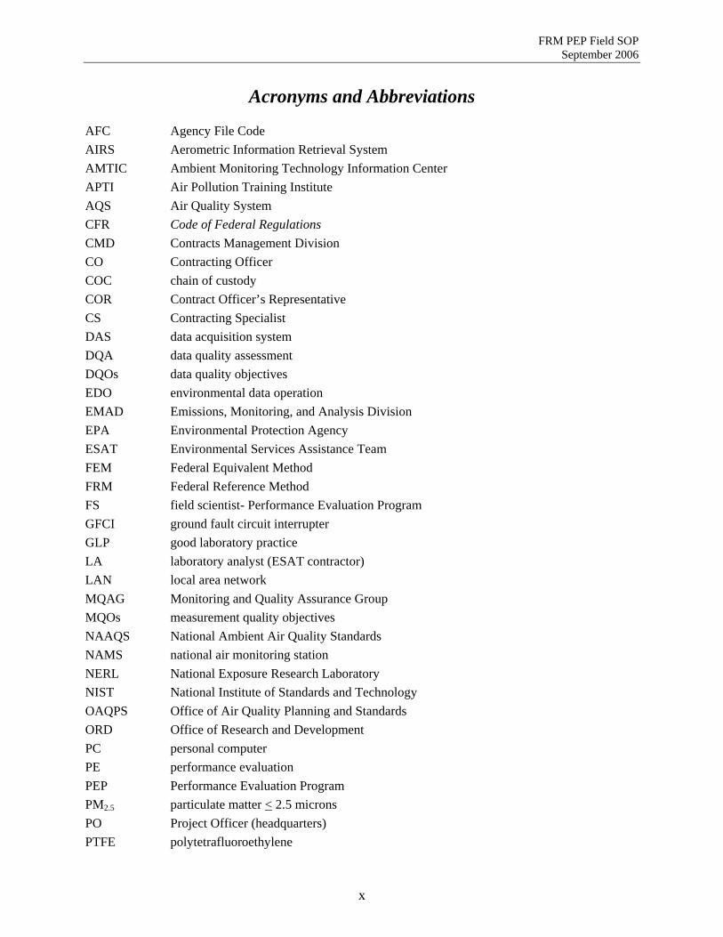
Acronyms and Abbreviations AFC Agency File Code AIRS Aerometric Information Retrieval System AMTIC Ambient Monitoring Technology Information Center APTI Air Pollution Training Institute AQS Air Quality System CFR Code of Federal Regulations CMD Contracts Management Division CO Contracting Officer COC chain of custody COR Contract Officer’s Representative CS Contracting Specialist DAS data acquisition system DQA data quality assessment DQOs data quality objectives EDO environmental data operation EMAD Emissions, Monitoring, and Analysis Division EPA Environmental Protection Agency ESAT Environmental Services Assistance Team FEM Federal Equivalent Method FRM Federal Reference Method FS field scientist- Performance Evaluation Program GFCI ground fault circuit interrupter GLP good laboratory practice LA laboratory analyst (ESAT contractor) LAN local area network MQAG Monitoring and Quality Assurance Group MQOs measurement quality objectives NAAQS National Ambient Air Quality Standards NAMS national air monitoring station NERL National Exposure Research Laboratory NIST National Institute of Standards and Technology OAQPS Office of Air Quality Planning and Standards ORD Office of Research and Development PC personal computer PE performance evaluation PEP Performance Evaluation Program PM2.5 particulate matter < 2.5 microns PO Project Officer (headquarters) PTFE polytetrafluoroethylene
x
FRM PEP Field SOP September 2006
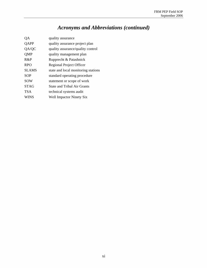
Acronyms and Abbreviations (continued) QA quality assurance QAPP quality assurance project plan QA/QC quality assurance/quality control QMP quality management plan R&P Rupprecht & Patashnick RPO Regional Project Officer SLAMS state and local monitoring stations SOP standard operating procedure SOW statement or scope of work STAG State and Tribal Air Grants TSA technical systems audit WINS Well Impactor Ninety Six
xi

FRM PEP Field SOP September 2006
[This page intentionally left blank.]
xii

FRM PEP Field SOP Introduction
Revision 2 Date: 9/30/2006
Field Standard Operating Procedures for the PM2.5 FRM Performance Evaluation Program
Introduction
Name: Printed Signature Date
Dennis Crumpler
Contents Section Page Introduction................................................................................................................................................. xv
PM2.5 Program................................................................................................................................... xv The Federal Reference Method Performance Evaluation Program................................................... xv Purpose of this Document ................................................................................................................. xx Prerequisites .....................................................................................................................................xxi Definitions.......................................................................................................................................xxii Cautions ..........................................................................................................................................xxii
Figures Page 1 Definition of independent assessment.............................................................................................xvii 2 Performance Evaluation Program implementation summary. .......................................................xviii Table Page 1 Required Reading for the Performance Evaluation Program..........................................................xxii
xiii

FRM PEP Field SOP Introduction
Revision 2 Date: 9/30/2006
[This page intentionally left blank.]
xiv
FRM PEP Field SOP Introduction
Revision 2 Date: 9/30/2006
Introduction The purpose of this section is to provide the Environmental Services Assistance Team (ESAT) Field Scientists (FSs) with background information on the PM2.5 program and the Federal Reference Method (FRM) Performance Evaluation Program (PEP) as an introduction to standard operating procedures (SOPs) for field personnel involved in the PEP.
PM2.5 Program In general, the measurement goal of the PM2.5 Ambient Air Quality Monitoring Program is to estimate the concentration, in units of micrograms per cubic meter (Fg/m3 ), of particulates of aerodynamic diameters less than or equal to 2.5 micrometers (Fm) that have been collected on a 46.2mm Teflon™ (polytetrafluoroethylene or PTFE) filter. In order to understand the size of 2.5 Fm, a human hair is approximately 50 Fm in diameter. One major objective for the collection of the data is to compare PM2.5 concentrations to the annual (15.0 Fg/m3 annual arithmetic mean concentration) and daily (65 Fg/m3 24-hour average concentration) National Ambient Air Quality Standard (NAAQS). A description of the NAAQS and its calculation can be found in the July 18, 1997 Federal Register notice. In addition, Appendix L of 40 Code of Federal Regulations (CFR) part 50 also provides the following summary of the measurement principle:
An electrically powered air sampler draws ambient air at a constant volumetric flow rate into a specially shaped inlet and through an inertial particle size separator (impactor) where the suspended particulate matter in the PM2.5 size range is separated for collection on a polytetrafluoroethylene (PTFE) filter over the specified sampling period. The air sampler and other aspects of this reference method are specified either explicitly in this appendix or generally with reference to other applicable regulations or quality assurance guidance.
Each filter is weighed (after moisture and temperature equilibration) before and after sample collection to determine the net weight (mass) gain due to collected PM2.5. The total volume of air sampled is determined by the sampler from the measured flow rate at actual ambient temperature and pressure and the sampling time. The mass concentration of PM2.5 in the ambient air is computed as the total mass of collected particles in the PM2.5 size range divided by the actual volume of air sampled and is expressed in micrograms per actual cubic meter of air (Fg/m3 ).
The Federal Reference Method Performance Evaluation Program Because the data for the state and local air monitoring stations (SLAMS) and national air monitoring stations (NAMS) network are used for NAAQS comparisons, the quality of these data is very important. A quality system has been developed to control and evaluate the quality of data to assure that NAAQS determinations are within an acceptable level of confidence. During the development of the PM2.5 NAAQS, the U.S. Environmental Protection Agency (EPA) used the data quality objective (DQO) process to determine the allowable measurement system imprecision and bias that would not significantly affect a decision-maker’s ability to compare pollutant concentrations to the NAAQS. The precision requirement (10% CV) and bias requirement (+10%) are based on total measurement uncertainty, which incorporates errors coming from all phases (e.g., field sampling, handling, analysis) of the measurement
xv

FRM PEP Field SOP Introduction
Revision 2 Date: 9/30/2006
process. The collocated samples provide adequate estimates of precision. The FRM performance evaluation (PE), if properly implemented, can provide the bias estimate. The PEP is a quality assurance (QA) activity that will be used to evaluate measurement system bias of the PM2.5 monitoring network. The pertinent regulations for this PE are found in 40 CFR Part 58, Appendix A, Section 3.5.3. The strategy is to collocate a portable FRM PM2.5 air-sampling instrument within 1 to 4 meters of a routine SLAMS/NAMS PM2.5 air-monitoring instrument, operate both monitors, and then to compare the results.
The implementation of the FRM PE is a state/local responsibility; however, due to a number of comments made during the review period for the December 13, 1997, PM2.5 NAAQS proposal, EPA assessed the FRM PEP and consequently made the following revisions:
# Modified the system to include an independent FRM PE
# Reduced the burden of this program by changing the audit frequency from 100% to 25% of the PM2.5 sites
# Reduced the audit frequency from six to four times per year
# Made allowances to shift the implementation burden from the state and local agencies to the federal government.
In September 2006, the FRM PE requirement was further modified as follows:
Primary quality assurance organizations with 5 or less PM2.5 monitoring sites would be required to have 5 valid audits per year distributed across the 4 quarters; primary quality assurance organizations with greater than 5 sites would be required to have 8 valid audits per year distributed across the 4 quarters.
100 percent completeness (meaning whatever it takes to get 5 or 8 valid samples)
All samplers subject to an audit within 6 years.
A PE is defined as a type of audit in which the quantitative data generated in a measurement system are obtained independently and compared with routinely obtained data to evaluate the proficiency of the analyst or laboratory. In the case of the PEP, the goal is to evaluate total measurement system bias, which includes measurement uncertainties from both field and laboratory activities. Independent assessment (Figure 1) was defined by the PM2.5 QA Workgroup to ensure that the appropriate level of independence is maintained during state and local implementation of the PEP.
Sites in the national monitoring network include those using FRM/FEM samplers, sites employing continuous analyzers, chemical speciation sites, visibility measurement sites, and special-purpose monitoring sites.
During the months of August through October 1997, EPA discussed the possibility of Federal Implementation of the PEP with the EPA Regions, Standing Air Monitoring Work Group (SAMWG), and various state and local organizations (e.g., Northeast States for Coordinated Air Use Management [NESCAUM], Mid Atlantic Regional Air Management Association [MARAMA], Western States Air Resources Council [WESTAR], and individual organizations). The majority of the responses from these organizations were towards federal implementation of the PEP.
xvi

FRM PEP Field SOP Introduction
Revision 2 Date: 9/30/2006
Independent assessment - An assessment performed by a qualified individual, group, or organization that is not part of the organization directly performing and accountable for the work being assessed. This auditing organization must not be involved with the generation of the routine ambient air monitoring data. An organization can conduct the FRM PE if it can meet the above definition and has a management structure that, at a minimum, allows for the separation of its routine sampling personnel from its auditing personnel by two levels of management, as illustrated in Figure 1. In addition, the pre- and post-sample weighing of audit filters must be performed by separate laboratory facility using separate laboratory equipment. Field and laboratory personnel would be required to meet the FRM Performance Audit field and laboratory training and certification requirements.
Organization3rd Level
Supervision
Organization2nd Level Supervision
Organization 1st Level
Supervision
OrganizationPersonnel
QA Lab Analysis
Organization1st Level
Supervision
OrganizationPersonnel
QA Field Sampling
Organization2nd Level
Supervision
Organization1st Level
Supervision
Organization Personnel
Routine Lab Analysis
Organization1st Level
Supervision
OrganizationPersonnel
Routine Field Sampling
Organizations planning to implement the FRM PE must submit a plan demonstrating independence to the EPA Regional Office responsible for overseeing QA-related activities for the ambient air monitoring network.
Figure 1. Definition of independent assessment.
xvii

FRM PEP Field SOP Introduction
Revision 2 Date: 9/30/2006
EPA investigated potential contracting mechanisms to help implement this activity and will use the ESAT contract currently in place in each EPA Region to provide the necessary field and laboratory activities. Each EPA Region will implement the field component of this activity, while a national EPA weighing laboratory operates the laboratory component.
The FRM PEP can be segregated into a field component and a laboratory component. The following information provides a brief description of these activities. Figure 2 provides a basic description of the PEP in five steps:
1. EPA will send filters to the weighing laboratory, where they will be checked, equilibrated, labeled, weighed, and prepared for the field.
2. The weighing laboratory will load the filters into cassettes and ship them with their accompanying Chain of Custody (COC) Forms to the EPA Regions.
3. The FS staff will take the filter cassettes, Field Data Sheets, and COC Forms to the field and operate the portable sampler.
4. The FS staff will send the exposed filter cassettes, data (e.g., diskette or other portable media), Field Data Sheets, and COC Forms back to the weighing laboratory (as well as keep a set of data and records).
5. The weighing laboratory will equilibrate/weigh filters, validate data, and approve data that are to be loaded into the Aerometric Information Retrieval System (AIRS), Air Quality Subsystem (AQS).
Figure 2. Performance Evaluation Program implementation summary.
Regions 1-10 Field Work
2 CHAIN
OF CUSTODY
CHAINOF
CUSTODY&
FIELDFORMS
CHAINOF
CUSTODY&
FIELDFORMS
3
4
Validated Data5
4
OAQPS
Field CHAIN
OFCUSTODY
National Weighing Lab
AQS
&FIELD
FORMS
Unexposed Filter
1
New Filters
xviii

FRM PEP Field SOP Introduction
Revision 2 Date: 9/30/2006
Field Activities
The FRM portable audit samplers will be used in a collocated manner to perform the evaluations. These samplers have been approved by EPA as an FRM and are designed to be durable, rugged, and capable of frequent transport. These samplers are constructed in modules, with each module weighing no more than 40 lbs. The total weight of the sampler itself must not be more than 120 lbs. Although these samplers have been specifically designed to perform these evaluations, precautions must be taken to ensure the quality of the data. Specific and detailed instructions can be found in the PEP Quality Assurance Project Plan (QAPP) and throughout these SOPs. A brief summary of the field activities follows:
# One fully trained FS will transport a portable PM2.5 FRM PE sampling device to an established PM2.5 site, which shall be located at any of the SLAMS/NAMS sites within each EPA Region.
# The FS will assemble the instrument, collocate the sampler, perform verifications, install a filter cassette, and operate the instrument following EPA requirements (midnight to midnight local standard time).
# If scheduling allows, the FS will leave this location to set up an additional 24-hour PE sampling device at another routine sampling location. If the schedule does not allow for another set up, the FS may perform additional activities at the site. The FS may also perform any required maintenance or repair of the portable PM2.5 sampling device, followed by a calibration verification.
# The FS will return to each site after the 24-hour sampling time, download the stored electronic monitoring data, remove and properly store the filter for transport, and disassemble the instrument.
# The FS will properly package the filter cassette, Field Data Sheets, COC Forms, and data storage media following the SOPs for shipment to the predetermined weighing laboratory.
Laboratory Activities
The FRM PE also requires extensive laboratory activities, including filter handling, equilibration, weighing, and data entry/management and archival. Specific and detailed instructions can be found in the PEP QAPP and the FRM PEP Laboratory SOP. In addition to the good laboratory practices (GLPs) that must be followed, the following activities must also be observed:
# Adherence to the vendor’s operations manual for the proper operation of the weighing devices, including the proper assembly, transport, calibration, and operation of the microbalances
# Adherence to the SOPs for this program
# Adherence to the standards, principles, and practices outlined in the PEP QAPP
# Completion of the required certification training program
# Special attention to any activity involving filter handling (e.g., pre-sampling equilibration, weighing, post-sampling equilibration, transport). This area contains the greatest potential for measurement uncertainty, and care must be given to the proper handling of the 46.2 mm Teflon™ filter used in the PE.
xix

FRM PEP Field SOP Introduction
Revision 2 Date: 9/30/2006
Pre-sampling Weighing
# Filters will be received from EPA and examined for integrity based upon EPA-approved SOPs.
# Filters will be enumerated for data entry.
# Filters will be equilibrated and weighed according to SOPs.
# Filters will be prepared for field activities or stored according to SOPs.
# The laboratory will develop and maintain shipping/receiving supplies and consumables, including containers, cold packs, max/min thermometers, and COC requirements/documentation.
Post-sampling Weighing
# Filters will be received in the laboratory, checked for integrity (e.g., damage-temperature, COC), and logged in.
# Filters will be archived (cold storage) until ready for weighing.
# Filters will be brought into the weighing facility and equilibrated for 24 hours (per SOPs).
# Filters will be weighed according to SOPs and the data will be entered.
# Field data will be entered into the data entry system to calculate a concentration.
# Filters will be stored in archive for 1 year at 4oC and 2 years at ambient temperature.
# Required data will be transferred to the AIRS/AQS database. Purpose of this Document
The purpose of the FRM PEP Field SOPs is to provide detailed procedures to follow when performing the following field activities:
# Overview
# Planning/preparation
# Equipment inventory/maintenance
# Cassette receipt/storage/handling
# Sampler transport and placement
# Sampler assembly and maintenance
# Verifications
# Calibrations
# Sample filter handling
# Filter COC
# Quality assurance/quality control
# Information retention. All methods are to be followed completely. Any deviation must be reported in writing and submitted to the ESAT Contract Officer’s Representative (COR). Method improvements are encouraged.
xx

FRM PEP Field SOP Introduction
Revision 2 Date: 9/30/2006
NOTE: If any deviations or modification offer a more efficient method or technique or serve to maintain or improve data quality, these proposed changes shall be made in writing to the ESAT COR.
Each SOP section is written as a stand-alone procedure to assist in training and certification activities and can be removed from the document and made readily available at the station where the activity takes place. The SOP sections are labeled for reference as PEPF-X, where PEPF indicates the Performance Evaluation Program Field SOPs and X indicates the section number. The SOPs follow the format for technical SOPs outlined in EPA’s Guidance for the Preparation of Standard Operating Procedures (SOPs) EPA QA/G-6. The QA/G-6 requirements include the following topics:
A. Scope and Applicability
B. Summary of Method
C. Definitions (acronyms, abbreviations, and specialized forms used in the SOPs)
D. Health & Safety Warnings
E. Cautions
F. Interferences
G. Personnel Qualifications
H. Apparatus and Materials
I. Instrument or Method Calibration
J. Sample Collection
K. Handling and Preservation
L. Sample Preparation and Analysis
M. Troubleshooting
N. Data Acquisition, Calculations, & Data Reduction
O. Computer Hardware & Software
P. Data Management & Records Management. Prerequisites
Training and Certification
All field personnel funded by the OAQPS PEP work assignment must be trained and certified to perform the activities. Training and recommendation for certification can be provided by the Regional COR or by OAQPS.
Background Reading
Prior to implementing field activities, field personnel are expected to be familiar with the documents listed in Table 1. The knowledge level is rated from 1, having in-depth knowledge, to 5, having a basic understanding.
xxi

FRM PEP Field SOP Introduction
Revision 2 Date: 9/30/2006
Table 1. Required Reading for the Performance Evaluation Program
Document Knowledge Level FRM PEP Field SOPs 1 FRM PEP QAPP 1 Portable Sampler Operating Manuals 1 FRM PEP Laboratory SOPs 3 QA Guidance Document 2.12 3 FRM PEP Implementation Plan 3 PM2.5 DQO Process 3 QA Handbook Vol. II Part 1 3 40 CFR Part 50 Appendix L 4 40 CFR Part 58 Appendix A 4
Definitions
Appendix A contains a glossary of the terms used in the PEP. Acronyms and abbreviations can be found in the front of this compendium.
Cautions
Filters
Care in all aspects of filter cassette handling cannot be overemphasized. The filters used for the PM2.5 sampler are comparatively small, with each filter weighing around 150 mg. Due to the size and weight of the particles that will be collected on these filters, net weights will be measured in micrograms (Fg). The loads on the filter may be anywhere from 10 to 2000 Fg (83 Fg/m3), with most sample loads around 300 Fg. In order to give one a sense of this weight, a 4 cm-long human hair weighs ~312 Fg. This average 300 Fg sample load value represents 0.2% of the weight of the blank filter. In addition, it is expected that the laboratory analyst (LA) will be able to duplicate weighings of the same filter to within 15 Fg. A single thumbprint on a filter weighs 15 Fg. It should be apparent that any small loss or gain (e.g., finger oils, dust) will affect filter weights. Additional details of filter cassette handling are discussed in Section 3.
xxii

FRM PEP Field SOP Section 1
Revision 2 Date: 9/30/2006
Field Standard Operating Procedures for the PM2.5 FRM Performance Evaluation Program
Section 1
Overview of FRM Performance Evaluation Field Activities SOP: PEPF-1
Name: Printed Signature Date
Dennis Crumpler
Contents Section Page 1.1 Overview of FRM Performance Evaluation Field Activities ...........................................................1-3
1.1.1 Scope and Applicability ......................................................................................................1-3 1.1.2 Summary of Method ...........................................................................................................1-3 1.1.3 Definitions...........................................................................................................................1-3 1.1.4 Health and Safety Warnings................................................................................................1-3 1.1.5 Cautions ..............................................................................................................................1-3 1.1.6 Interferences........................................................................................................................1-4 1.1.7 Personnel Qualifications .....................................................................................................1-5 1.1.8 Equipment and Supplies......................................................................................................1-5 1.1.9 Procedures...........................................................................................................................1-5 1.1.10 References ...........................................................................................................................1-7
Figures Page 1-1 Field activities in relation to SOPs...................................................................................................1-6
1-1

FRM PEP Field SOP Section 1
Revision 2 Date: 9/30/2006
[This page intentionally left blank.]
1-2

FRM PEP Field SOP Section 1
Revision 2 Date: 9/30/2006
1.1 Overview of FRM Performance Evaluation Field Activities 1.1.1 Scope and Applicability
This Standard Operating Procedure (SOP) applies to performing field operations for the Federal Reference Method (FRM) Performance Evaluation Program (PEP) and provides an overview of the detailed SOPs that follow.
1.1.2 Summary of Method
A Performance Evaluation (PE) is used to determine the total bias for PM2.5 collection and gravimetric analysis. This type of event involves collocating a portable FRM sampler adjacent to a monitoring site’s routine sampler and sampling for a 24-hour period. The concentrations measured by the two samplers are then compared to assess bias. FRM PEs will be conducted as follows:
Primary quality assurance organizations with 5 or less PM2.5 monitoring sites are required to have 5 valid audits per year distributed across the 4 quarters; primary quality assurance organizations with greater than 5 sites are required to have 8 valid audits per year distributed across the 4 quarters.
100 percent completeness (meaning whatever it takes to get 5 or 8 valid samples)
All samplers subject to an audit within 6 years.
Special priority will be given to those sampler locations documented or expected to have concentrations near the annual National Ambient Air Quality Standard (NAAQS) for PM2.5 (40 CFR Part 58, Appendix A, Section 3.5).
The basic operations involved with conducting the field portion of the FRM PEP are described in the SOP sections contained in this document.
1.1.3 Definitions
Appendix A contains a glossary of terms used in the PEP.
1.1.4 Health and Safety Warnings
To prevent personal injury, all personnel must heed any warnings associated with the installation and operation of the PM2.5 sampler and any supporting equipment and supplies. Specific health and safety warnings will generally be found at the point in the operating manual or troubleshooting guide where they are most applicable.
1.1.5 Cautions
# Because the portable FRM PM2.5 sampler will be moved from site to site, it is of critical importance that it be maintained and calibrated as required and that all aspects of its operation be checked and verified after it is set up at each new site. To function as a reliable standard of comparison, the sampler’s operational parameters must be kept within tight control limits. Consequently, procedures for verifying a portable FRM sampler's calibration and operability are an important part of the field SOPs.
1-3

FRM PEP Field SOP Section 1
Revision 2 Date: 9/30/2006
# The FRM PM2.5 sampler will be installed and dismantled many times in the course of the PE
trips, and caution must be taken to install and maintain the sampler properly to prevent damage. Be particularly attentive to performing maintenance on the pump; ensuring the soundness of electrical and pneumatic connections that will be repeatedly assembled and disassembled; and cleaning the interior and exterior surfaces of the inlet and the Well Impactor Ninety Six (WINS). Refer to the Operations Manual for exact instructions on packing the portable sampler, and pack the sampler components securely for safe transport by vehicle or by air. Immediately after installation, leak checks must be performed and verification checks of temperature, barometric pressure, and flow rate sensors must be made and recorded. All necessary corrective actions must be taken before sampling can begin with the portable FRM device.
# The 46.2-mm polytetrafluoroethylene (PTFE) filters used for sampling are especially delicate and easily damaged. Exercise care in handling new and used filters. Never touch the filter surfaces; handle the filters only by touching the cassette surfaces. Never remove the filters from their cassettes; this is done only at the weighing laboratory. If details concerning labeling and transporting of filters are not followed precisely, errors will result. Rough handling of used filters during packaging or transport should be avoided. Exposed filters must be shipped at approximate temperatures of less than 4°C to minimize the potential for weight loss.
# Care should be taken to use the appropriate type of filter cassette with each FRM sampler model. The BGI and Andersen FRM samplers can use filter cassettes made by either BGI or Andersen. The Rupprecht & Patashnick (R&P) sampler users its own cassette and cannot use those from other manufacturers.
# When the sampler is dismantled, be sure to remove any debris adhering to the base or legs before storing the sampler for transport. To minimize contamination, pack the base or leg portion of the sampler separately from the sampler collection module.
# Protect all barometers from mechanical shock and sudden changes in pressure.
1.1.6 Interferences
The interferences associated with this method are those factors that can cause alterations to the flow rate of the sampler or in the weight of the filter and/or sampled PM2.5. If inadvertently transferred to the filter surface in the sample collection filter enclosure, a small particle of dust or pollen will alter the sample weight dramatically. Interferences can be avoided by following these guidelines:
# Avoid handling unexposed or exposed filters in any way that could add or subtract weight. For example, rough handling could cause weight loss, exposing of the filter to dusts or pollen could cause weight gain, and allowing the face of the filter to touch surfaces could cause either weight loss or gain.
# Following a sampling period, package the filter promptly and return it to the weighing laboratory within the specified time.
# Certain types of particulate matter are somewhat volatile; therefore, exposed filters must be shipped in a package cooled ideally at or below 4 °C to minimize loss of volatile material.
# Ensure proper cleaning of the inlet, downtube, and WINS impactor to avoid any contamination of the flow devices; use required techniques for the leak check to identify and correct any leaks found within the flow system. Operation of the FRM sampler with incorrect flow rates or with a damaged WINS impactor can allow larger particles to be collected as interferents.
1-4

FRM PEP Field SOP Section 1
Revision 2 Date: 9/30/2006
1.1.7 Personnel Qualifications
All personnel responsible for conducting FRM PEs at field sites must be certified by the U.S. Environmental Protection Agency (EPA) as completing a required training program. These persons are designated as Field Scientists (FS). During this training program, the operators of the samplers must successfully complete an extensive, hands-on training session specified by EPA’s Office of Air Quality Planning and Standards (OAQPS). An FS must also complete a written exam with a passing score of 80% or better. These training programs will be conducted as required at locations throughout the United States to ensure that all operators of the portable samplers are certified and that an adequate number of PE FS staff are available in each EPA Region. A technical systems audit (TSA) of the FS may replace the hands-on practical examination for annual recertification. Contact the regional EPA office or OAQPS for more information about training schedules and locations. The FS shall be prepared to transport the FRM device to various sampling platforms, including the tops of buildings or distant rural settings. For ease of operation and the safety of the operators, the portable FRM sampler was designed in sections, with each individual section weighing no more than 40 lbs. Field personnel must be able to lift and carry these sections up stairs and/or ladders.
1.1.8 Equipment and Supplies
Each organization responsible for performing the FRM PE will develop standard “kits” of equipment, materials, and supplies suitable for the make(s) and model(s) of the portable FRM sampler(s) to be used. The contents of these kits will also be determined by the different requirements of the sites to be visited for FRM PEs. For example, mounting equipment will, in part, be dictated by how the sites are constructed and where they are mounted (e.g., building roof, concrete pad, wooden platform).
Section 2.1 contains an example field inventory list and discusses the procedures for field equipment and resupply. The example list must be translated into a specific checklist of equipment and materials for each organization. Communications between the FS and site personnel prior to the visit are essential and assist greatly in knowing what will be required at each site.
1.1.9 Procedures
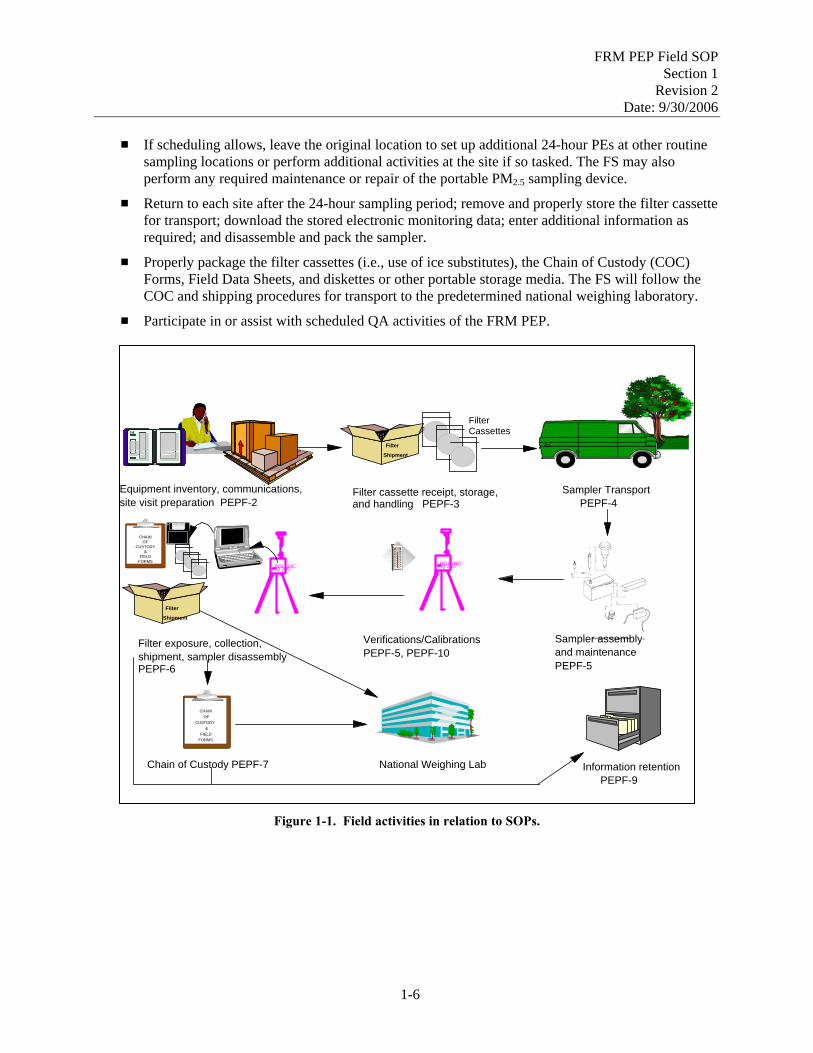
The FS will perform the following activities, as illustrated in Figure 1-1:
# Receive equipment and consumables, inventory each item, and ensure supplies are adequate to perform field activities.
# Receive pre-weighed cassettes containing filters from a national laboratory and confirm receipt of the filter cassettes by informing the laboratory. Filter cassettes will be used in the order in which they are received, paying special attention to the “use by” dates on the custody forms.
# Assist in developing a plan for the implementation of field activities and gather pertinent information for each site on a Site Data Sheet.
# Transport the appropriate sampling equipment to sites.
# Assemble the portable sampler; collocate the PEP sampler with a sampler from the monitoring organization; perform verifications following SOPs; install a filter cassette; and operate the instrument for 24 hours (midnight to midnight).
1-5
FRM PEP Field SOP Section 1
Revision 2 Date: 9/30/2006
# If scheduling allows, leave the original location to set up additional 24-hour PEs at other routine
sampling locations or perform additional activities at the site if so tasked. The FS may also perform any required maintenance or repair of the portable PM2.5 sampling device.
# Return to each site after the 24-hour sampling period; remove and properly store the filter cassette for transport; download the stored electronic monitoring data; enter additional information as required; and disassemble and pack the sampler.
# Properly package the filter cassettes (i.e., use of ice substitutes), the Chain of Custody (COC) Forms, Field Data Sheets, and diskettes or other portable storage media. The FS will follow the COC and shipping procedures for transport to the predetermined national weighing laboratory.
# Participate in or assist with scheduled QA activities of the FRM PEP.
Figure 1-1. Field activities in relation to SOPs.
Filter Cassettes
Shipment
Filter
Equipment inventory, communications, site visit preparation PEPF-2
Sampler Transport Filter cassette receipt, storage, PEPF-4 and handling PEPF-3
Sampler assembly and maintenance PEPF-5
Verifications/CalibrationsPEPF-5, PEPF-10
Filter exposure, collection, shipment, sampler disassembly PEPF-6
50COCO
40302010 01020304050
120FFOO
10080
020
204060
6040
CHAIN OF
CUST ODY&
FIELD FORMS
Shipment Filter
CHAIN OF
CUST O& DY
FIELD FORMS
National Weighing LabChain of Custody PEPF-7
BGI, INPQ 200 CBGI, INCPQ 200
Information retention PEPF-9
1-6
FRM PEP Field SOP Section 1
Revision 2 Date: 9/30/2006
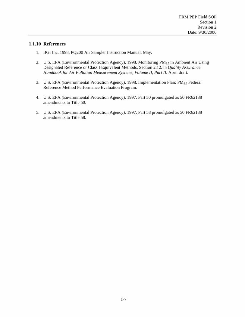
1.1.10 References
1. BGI Inc. 1998. PQ200 Air Sampler Instruction Manual. May.
2. U.S. EPA (Environmental Protection Agency). 1998. Monitoring PM2.5 in Ambient Air Using Designated Reference or Class I Equivalent Methods, Section 2.12. in Quality Assurance Handbook for Air Pollution Measurement Systems, Volume II, Part II. April draft.
3. U.S. EPA (Environmental Protection Agency). 1998. Implementation Plan: PM2.5 Federal Reference Method Performance Evaluation Program.
4. U.S. EPA (Environmental Protection Agency). 1997. Part 50 promulgated as 50 FR62138 amendments to Title 50.
5. U.S. EPA (Environmental Protection Agency). 1997. Part 58 promulgated as 50 FR62138 amendments to Title 58.
1-7
FRM PEP Field SOP Section 1
Revision 2 Date: 9/30/2006
[This page intentionally left blank.]
1-8

FRM PEP Field SOP Section 2
Revision 2 Date: 9/30/2006
Field Standard Operating Procedures for the PM2.5 FRM Performance Evaluation Program
Section 2
Planning and Preparing for PEP Sampling Events SOP: PEPF-2
Name: Printed Signature Date
Dennis Crumpler
Contents Section Page
2.1 Equipment Inventory and Storage....................................................................................................2-3 2.1.1 Scope and Applicability...................................................................................................2-3 2.1.2 Definitions .......................................................................................................................2-3 2.1.3 Personnel Qualifications ..................................................................................................2-3 2.1.4 Equipment and Supplies ..................................................................................................2-3 2.1.5 Procedure .........................................................................................................................2-3
2.2 Communications ............................................................................................................................2-15 2.2.1 Scope and Applicability.................................................................................................2-15 2.2.2 Summary of Method ......................................................................................................2-15 2.2.3 Definitions .....................................................................................................................2-15 2.2.4 Equipment and Supplies ................................................................................................2-16 2.2.5 Phone Communications .................................................................................................2-16 2.2.6 Monthly Progress Reports .............................................................................................2-17 2.2.7 Records Management.....................................................................................................2-18
2.3 Preparation for PEP Sampling Events............................................................................................2-23 2.3.1 Scope and Applicability.................................................................................................2-23 2.3.2 Summary of Method ......................................................................................................2-23 2.3.3 Definitions .....................................................................................................................2-23 2.3.4 Personnel Qualifications ................................................................................................2-23
2-1

FRM PEP Field SOP Section 2
Revision 2 Date: 9/30/2006
2.3.5 Cautions .........................................................................................................................2-23 2.3.6 Equipment and Supplies ................................................................................................2-23 2.3.7 Procedure .......................................................................................................................2-24 2.3.8 References......................................................................................................................2-31
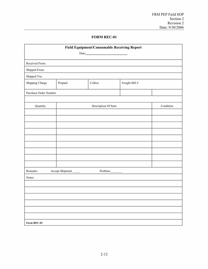
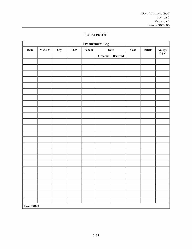
Tables Page Table 2-1. Equipment and Supplies ...........................................................................................................2-4 Table 2-2. General Siting Requirements for PM2.5 PEP Samplers...........................................................2-27 Table 2-3. Implementation Summary ......................................................................................................2-29 Figures Page Figure 2-1. Line of communication. ........................................................................................................2-15 Figure 2-2 Critical filter holding times. ...................................................................................................2-29 Forms Page INV-01 Field Inventory Form............................................................................................................2-11 REC-01 Field Equipment/Consumable Receiving Report .................................................................2-12 PRO-01 Procurement Log ..................................................................................................................2-13 COM-1 Phone Communication Form................................................................................................2-21 COM-2 Monthly Progress Report......................................................................................................2-22 SD-01 Site Data Sheet .....................................................................................................................2-35
2-2

FRM PEP Field SOP Section 2
Revision 2 Date: 9/30/2006
2.1 Equipment Inventory and Storage 2.1.1 Scope and Applicability
This SOP explains the activities involved in conducting an inventory of existing field equipment, receiving new equipment and consumables, and maintaining the equipment.
2.1.2 Definitions
Appendix A contains a glossary of the terms used in the PEP.
2.1.3 Personnel Qualifications
Personnel who conduct the FRM PEs must have attended an initial training course, which includes lectures, demonstrations, hands-on practice, a written exam for which a passing score of 80% is achieved, and a hands-on practical training examination. Annual recertification requirements include a written and hands-on practical training examination. A technical systems audit (TSA) of the FS may replace the hands-on practical examination for annual recertification.
2.1.4 Equipment and Supplies
The following apparatus and materials are required to perform the procedures in this section:
# Table 2-1, which provides a listing of the equipment and consumables needed for the field # Field Inventory Form (INV-01) # Field Procurement Log (PRO-01).
2.1.5 Procedure
2.1.5.1 Equipment Inventory
Table 2-1 provides a listing of the capital equipment and consumables required. The FS will follow the procedure below:
# Select Field Inventory Form (INV-01) # Take a complete inventory of all equipment and supplies # Keep an original copy and file it under Agency file code “PEP/301-093-006.6.” Provide a copy of
the inventory to the EPA Regional Contract Officer’s Representative (COR). The FS should maintain a two-month supply of consumables. During the first weeks of implementation, the FS will determine how quickly the consumable equipment supply is used and develop a purchasing schedule to ensure that an adequate supply is maintained.
Table 2-1 is a general list of equipment that has been found useful in the PEP. The FS should use this as a basis for preparing a specific checklist of equipment and materials for their organization. Communications between the FS and site personnel prior to the visit are essential and assist greatly in knowing what will be required at each site.
2-3

FRM PEP Field SOP Section 2
Revision 2 Date: 9/30/2006
Table 2-1. Equipment and Supplies
Qty. PEP Field Equipment and Supplies Vendor/Catalog # Make/Model # T Monitoring Equipment and Supplies Transport cases for loose equipment/consumables Forestry Suppliers/31113 Collapsible crate Backpack frame for carrying samplers Forestry Suppliers/35913 Portable FRM PM2.5 sampler(s) with carrying case Pre-weighed 46.2-mm diameter filters in the proper cassette Supplied by weighing
laboratory
COC form for each filter cassette Impactor oil and dropper
(Note: Dow 704 has been found to solidify when sustained at 4°C for long periods.)
SPI Supplies Octoil®-S (SPI# 00031)
Impactor filters (37-mm diameter glass fiber) BGI (preferred) Teflon-coated tweezers (for handling impactor filters) Sample shipping containers (coolers) Custody seals (tape or stickers) Min/max thermometers Daigger/AX24081B Sentry Cold packs (ice substitutes), 36/box Daigger EF2592D
Electric transport cooler with 12 volt to ac transformer Globe Mart/5615-807 Coleman 16 quart Filter transport coolers (6 quart) Rubbermaid website Rubbermaid 6 pack Bubble wrap Consolidated Plastics 87604 FRM Operations Manual Field Notebook(s) Clipboard (8” x 14”) Forestry Suppliers/53283 Cruiser mate Grip binders Office Depot/501-627 Presstex Data storage media (e.g., diskette, CD, or USB card) Silicone grease for O-rings (e.g., vacuum grease) Daigger/AX23061A FRM PEP Field SOPs (this document) Field Data Sheets, preprinted Laptop computer with PQ200A job-control software Datatrans™ to download data BGI upgraded version 2006 BGI /DC201 Cables for connecting the data-download device to the portable
FRM sampler
Magnetic compass or other means of determining site orientation
Forestry Suppliers/37177 Suunto Partner II
Tape measure (metric) Forestry Suppliers/39651 Lufkin/ W 9210ME Cellular phone
Mechanical pencils Markers (indelible)
Skilcraft Sharpees
9mm Ultrafine
Mounting Equipment and Tools Ladder, rope for hoisting equipment Hand truck or cart with wheels and straps for transporting
equipment
Bubble level for checking the portable FRM sampler Mayes (torpedo) 10198
2-4

FRM PEP Field SOP Section 2
Revision 2 Date: 9/30/2006
Qty. PEP Field Equipment and Supplies Vendor/Catalog # Make/Model # T
Wooden shims or other means for leveling the portable FRM sampler
Tool box with basic tools including the following Allen wrenches (metric and standard)
Micro screw driver set Pliers (multiple sizes and types) Screwdrivers (standard straight and Philips head) Wire cutters Small synchs ties
Electrical tape Soldering gun/solder Hemostat (for flow rate troubleshooting) Flashlight with spare batteries Heavy-duty, grounded, weatherproof electrical extension cord
with multiple outlets (25 ft. length) Heavy-duty, grounded, weatherproof electrical extension cord with multiple outlets (12 ft. length)
Unicor
Unicor
Style3 Class2 Series2
Style3 Class2 Series2
Tie-down cables, anchors, plywood sheet, and bungee cords to anchor and stabilize the portable FRM sampler and to dampen vibration (optional)
Masking tape Packaging tape Strapping tape
GSA-7510-00-283-0612 GSA-7510-00-079-7906 GSA-7510-00-159-4450
Calibration/Verification Standards and Related Equipment Downtube flow rate adapter Temperature, pressure, and flow verification device (Delta-Cal
or Tri-Cal, with external temperature probe) BGI Delta-Cal BGI Tri-Cal
DC-1 TC-12
Temperature verification/calibration standard (NIST-traceable) with probe (optional)
VWR 61220-601
Styrofoam cup and deionized ice water for temperature calibrations
Flow-check filter in transport cassette Impermeable “filter” disk for internal leak checks Accurately set timepiece (cell phone) Hand calculator (scientific) Office Depot/397-554 Casio Spare Parts and Optional Equipment Spare O-rings for the portable FRM sampler Spare batteries (for all battery-powered equipment) Fuses, as required by all equipment used Spare in-line filters (if required by the portable FRM sampler) Voltmeter/ammeter/ohmmeter for troubleshooting Spare impactor(s) GFCI tester Portable GFCI device
2-5

FRM PEP Field SOP Section 2
Revision 2 Date: 9/30/2006
Qty. PEP Field Equipment and Supplies Vendor/Catalog # Make/Model # T
Camera (digital) for site pictures Cleaning Supplies and Equipment Low-lint laboratory wipes for cleaning WINS and other
sampling equipment (Kimwipes) Kimberly-Clark
Disposable paper towels Kay-Pees disposable paper towels
Large locking plastic bag for cleanup of debris, wipes Soft brush Supply of deionized water for cleaning and rinsing equipment Isopropyl alcohol to aid in removal of grease and dirt Alcohol Wipes for preloading hand wipe Nearest drug store Penetrating oil (silicone oil or 3-in-1™) Lint-free pipe cleaners Safety pin/dental pick Lint-free cotton-tipped swabs Wooden dowel and cloth wads to clean downtube Spray bottle Gloves (powder free, nitrile)
2.1.5.2 Procurement
As consumables run low or as new equipment purchases are necessary, the FS will be responsible for assisting in the procurement of these items following the policy and requirements described in the ESAT scope of work. The FS should continue purchasing consumable equipment with the same model numbers as initially procured unless the EPA COR suggests a different item due to improved quality, reduced contamination, improved ease of use, or lower cost (without sacrificing quality). The COR will report any equipment changes that could affect the results of sampling events to the national program manager.
Note: Federal procurements take a long time. Plan ahead! Allow 4-6 weeks for delivery. The following activities will be performed:
# Develop procurement requests as per EPA requirements # Upon order, add items to the Field Procurement Log (PRO-01) # Once a month, provide a copy of Field Procurement Log (PRO-01) to the COR # File Field Procurement Log (PRO-01) under Agency file code “PEP/301-093-006.6.”
2.1.5.3 Receipt of Consumable Equipment
Upon receiving equipment and consumables, the FS will perform the following activities:
# Pull the appropriate purchase order for the incoming items from the files
2-6

FRM PEP Field SOP Section 2
Revision 2 Date: 9/30/2006
# Fill out a Field Receiving Report Form (REC-01), compare the items and quantity against the
purchase order, and inspect the condition of each item # If the items received match the purchase order and the condition of the equipment or consumables
is acceptable, signify this on the form and file it under Agency file code “PEP/301-093-006.6” # If the quantity, items, or condition are not acceptable, complete REC-01 with appropriate remarks
and send a copy of the form to the COR # Add receipt information to the Field Procurement Log (PRO-01)
2.1.5.4 Equipment Storage
When not in use, equipment should be stored it in a clean, dry, and safe location. After completion of a field trip and return to the field office, the sampler(s) and associated verification gear should be cleaned, maintained as scheduled, and stored for the next trip. All equipment should be clearly identified, and readily available for the next scheduled field trip.
2-7

FRM PEP Field SOP Section 2
Revision 2 Date: 9/30/2006
[This page intentionally left blank.]
2-8

FRM PEP Field SOP Section 2
Revision 2 Date: 9/30/2006
Section 2.1: Equipment Inventory and Storage
Field Data Forms
2-9

FRM PEP Field SOP Section 2
Revision 2 Date: 9/30/2006
[This page intentionally left blank.]
2-10

FRM PEP Field SOP Section 2
Revision 2 Date: 9/30/2006
FORM INV-01
Field Inventory Form
Item Vendor Model # Quantity Purchase Date Warranty Form INV-01
2-11
FRM PEP Field SOP Section 2
Revision 2 Date: 9/30/2006
FORM REC-01
Field Equipment/Consumable Receiving Report
Date:___________________________
Received From:
Shipped From:
Shipped Via:
Shipping Charge
Prepaid Collect Freight Bill #
Purchase Order Number
Quantity Description Of Item Condition
Remarks: Accept Shipment _____ Problem________
Notes:
Form REC-01
2-12
FRM PEP Field SOP Section 2
Revision 2 Date: 9/30/2006
FORM PRO-01
Procurement Log
Date Item Model # Qty PO# Vendor
Ordered Received
Cost Initials Accept/ Reject
Form PRO-01
2-13

FRM PEP Field SOP Section 2
Revision 2 Date: 9/30/2006
[This page intentionally left blank.]
2-14

FRM PEP Field SOP Section 2
Revision 2 Date: 9/30/2006
2.2 Communications 2.2.1 Scope and Applicability
This procedure describes the methods and requirements necessary to communicate technical information between the PEP FS and the organizations intimately involved in the PEP, such as the following
# ESAT COR for the FS # ESAT CORs for the Laboratory Analyst (LA) # ESAT LAs # OAQPS.
This SOP focuses on FS communications and does not describe additional ESAT communication obligations described in the ESAT Scope of Work. Communications will include reports, e-mail messages, and phone calls.
2.2.2 Summary of Method
An organized communications framework is needed to facilitate the flow of information. Figure 2-1 represents the principal communications pathways. In general, ESAT contractors will be responsible for informing Regional CORs and Project Officers (POs) on technical progress, issues, and contractual obligations. On the technical side, the EPA Regional CORs will be responsible for communicating with state and local agencies and informing OAQPS about issus that require technical attention. Contractual issues will be conveyed from the ESAT contractor through POs to the ESAT Contracts Office and, if necessary, to OAQPS. Appendix D lists the important EPA ESAT contacts.
Figure 2-1. Line of communication.
The ESAT contractors will have frequent communication with the Regional CORs about the progress of their activities and any problems/issues associated with them. Resolution of these issues should take place in the Regions unless the issue could affect the implementation of the program at a national level, in which case it should be discussed and resolved through an ESAT Workgroup conference call.
2.2.3 Definitions
Appendix A contains a glossary of terms used in the PEP.
2-15

FRM PEP Field SOP Section 2
Revision 2 Date: 9/30/2006
2.2.4 Equipment and Supplies
The following capital and consumable equipment will be required for communications:
# Telephone # Laboratory PC - with Internet and EPA e-Mail capabilities # Printer # Field Communications Notebook # Writing utensils # Forms
- Phone Communication Form (COM-1) - Monthly Progress Report (COM-2).
2.2.5 Phone Communications
2.2.5.1 Non-routine Calls
A call may be initiated by the COR(s), the FS, or the laboratory at any time to discuss issues related to the PEP. During the conversation, the Phone Communication Form (COM-1) in the Field Communications Notebook will be used by the FS to record the highlights of the conversation. Notes will include the following:
# Date # Time # Personnel involved # Issue(s) # Decision(s) # Follow-up action(s) # Follow-up action responsibility # Follow-up action completed by (date).
If follow-up action is required by the FS, the actions will be included in the monthly progress reports (see Section 2.2.6). At a minimum, the FS will keep the original hardcopy in the Field Communications Notebook. The FS may also choose to keep an electronic record of this information on a PC.
2.2.5.2 Field Communications
Field communications can take place either by phone or e-mail. Phone messages or conversations will be recorded in the Field Communications Notebook. E-mail messages should be printed and stored in the Field Communications Notebook.
NOTE: The FS must document communications; however, there is some flexibility in exactly how it can be done. The COM Forms are a guide and may be used and archived as described above or as the FS sees fit. The FS is not required to have a separate notebook just for logging communications, but they must be logged in some fashion and filed in an orderly manner.
2-16

FRM PEP Field SOP Section 2
Revision 2 Date: 9/30/2006
2.2.5.3 Filter Cassette Shipment Receipt
Upon request from the FS, filter cassettes will be shipped to the field offices by the LA. On the day of receipt, the FS will contact the LA and provide the following information:
# Date of receipt # Number of filter cassettes in shipment # Number of boxes in shipment # Air bill number.
2.2.5.4 Equipment Shipment Receipt
Once a month, the laboratory will ship coolers, max/min thermometers, and gel packs back to the field offices. On the day of receipt, the FS will contact the LA and provide the following information:
# Date of shipment # Number of boxes in shipment # Tracking number.
2.2.5.5 ESAT Conference Calls
The FS may be asked to participate in ESAT Workgroup conference calls to discuss progress or resolution of issues. The COR will inform the FS of any materials or information that needs to be prepared for the call at least three days prior to the call. During the call, the FS will use the Phone Communication Form (COM-1) to record issues and action items that pertain to his or her activities. These items will be included in the next monthly progress report.
2.2.5.6 Communicating with Reporting Organizations and Site Operators
Dates for the FRM PE visits should be coordinated with the site’s normal operating schedule. This coordination must be done in advance so that both the FS and the site operator have ample notice and time to prepare for the on-site visit. The COR (or the FS, as delegated by the COR) will contact each site operator prior to the site visit. Contact must be made by telephone if within 30 days of the site visit, but email is sufficient otherwise. About one week prior to the actual evaluation, the FS will call the site operator to confirm that the PE visit remains on schedule and to confirm meeting arrangements. It is important to cover all details of the planned site visit and evaluation. (See Section 2.3.7.3 for additional details on recommended points of discussion.) Document the discussions and any action items using the Phone Communication Form (COM-1).
2.2.6 Monthly Progress Reports
The FS will provide a progress report to the COR in writing at the end of each month (deadline is the 15th calendar day of the following month, unless otherwise specified by the COR). The Monthly Progress Report (COM-2) will be used to convey the following information:
# Reporting Date – Beginning and end dates of the reporting period. # Reporter – Person writing report.
2-17

FRM PEP Field SOP Section 2
Revision 2 Date: 9/30/2006
# Progress – Progress on field activities
- Evaluations scheduled within reporting date - Evaluations conducted within reporting date.
# Issues - Old issues – Reported in earlier reports and not yet resolved - New issues – Arising within reporting date.
# Actions – Necessary to resolve issues; includes the person(s) responsible for resolving them and the anticipated dates when they will be resolved.
# Extra purchases. 2.2.7 Records Management
Monthly progress reports will be archived in the Field Reporting Package file under “PEP/404-142-01-173.” Phone communications will be archived in the Field Reporting Package file under “PEP/301-093-006.4.” See SOP PEPF-9, Information Retention, for details.
2-18
FRM PEP Field SOP Section 2
Revision 2 Date: 9/30/2006
Section 2.2: Communications
Field Data Forms
2-19

FRM PEP Field SOP Section 2
Revision 2 Date: 9/30/2006
[This page intentionally left blank.]
2-20

FRM PEP Field SOP Section 2
Revision 2 Date: 9/30/2006
FORM COM-1
Phone Communication Form
Date: Time: Recorder:
Personnel on call:
Issue(s):
Decisions(s):
Follow-up Action(s):
Follow-up Responsibilities:
Completion Dates for Follow-up Actions:
2-21

FRM PEP Field SOP Section 2
Revision 2 Date: 9/30/2006
FORM COM-2
Monthly Progress Report
Reporting Date: Start: End: Reporter:
Progress
Sites Scheduled for Month:
Sites Evaluated during Month:
Issues
Old:
New:
Actions:
Actions:
Free Form Notes:
2-22

FRM PEP Field SOP Section 2
Revision 2 Date: 9/30/2006
2.3 Preparation for PEP Sampling Events 2.3.1 Scope and Applicability
This SOP applies to preparing for the FRM PE site visits.
2.3.2 Summary of Method
Preparation for site visits in the FRM PEP requires attention to many details and interaction among several different organizations. This SOP outlines the planning steps necessary to successfully conduct PEs at one or more sites.
2.3.3 Definitions
Appendix A contains a glossary of terms used in the PEP.
2.3.4 Personnel Qualifications
Personnel who conduct the FRM PEs must have attended an initial training course, which includes lectures, demonstrations, hands-on practice, a written exam for which a passing score of 80% is achieved, and a hands-on practical training examination. Annual recertification requirements include a written and hands-on practical training examination. A technical systems audit (TSA) of the FS may replace the hands-on practical examination for annual recertification.
2.3.5 Cautions
# The FS must obey all laws, ordinances, and policies regarding access to monitoring sites and use of the property of others.
# The FS shall not represent himself or herself as an employee of EPA or of the federal government.
# The FS may not gain access to a monitoring site without the knowledge and permission of the site owner or site operator.
# The FS must comply with all applicable laws and regulations in transporting equipment and supplies, including those of the Federal Aviation Administration (FAA) and the U.S. Department of Transportation (DOT).
# The FS must comply with local ordinances, licensing requirements, and “union shop” agreements, where applicable. In general, the FS is expected to perform the tasks necessary to install and operate the FRM PE equipment; however, electrical rewiring or other modifications to monitoring site equipment must be done by qualified and properly licensed tradesmen.
2.3.6 Equipment and Supplies
# Implementation schedule # Site Data Sheet(s) (SD-01) # Contact information for reporting organization.
2-23

FRM PEP Field SOP Section 2
Revision 2 Date: 9/30/2006
2.3.7 Procedure
2.3.7.1 Development of Implementation Schedule
State and local organizations will work with the EPA Regions to select and develop a list of sites for the evaluations conducted in each calendar year on or before December 1 of the previous year. The Regional CORs, with the assistance of the ESAT contractors, will attempt to determine the most efficient site visit schedule. This schedule should be based upon the following:
# CFR requirements for audit frequency # Meeting the same monitoring schedule as the routine sampler being evaluated # Site proximity (the sites that are closest in proximity to each other can be visited within the same
day or week). It is difficult to provide a general procedure for scheduling site visits because of the number of variables, such as the number of sites, the number of samplers at each site, the distance between sites, the sampling schedule, and the site access restrictions.
FRM PEs should be implemented on a normal sampling day so that the evaluation does not create additional work for the state and local agencies. Thus, for sites that only sample one day in three or one day in six, this schedule must be taken into account when scheduling a PE site visit. However, if the state or local agency is amenable to perform a PE on a day other than a routine sampling day and is willing to post the result to AQS, the visit can be scheduled.
The scheduling approach should attempt to minimize travel costs and maximize the number of sites visited. Some suggestions for efficient scheduling include the following:
# Prioritize sites that are expected to be near or above the NAAQS. # Prioritize sites that are sampled less than every day. It may be best to prioritize sites on less
frequent sampling cycles because delays and schedule changes tend to accumulate during a circuit of sites. Visits to sites on a daily sampling cycle can be more flexible because the PE sample can be taken on any day.
# Select the sites to be evaluated by geographic area so that travel between sites is minimized. # Build in “downtime” for weather, sickness, or other unplanned delays.
Once the implementation schedule is developed, it must be sent to all affected reporting organizations. Based upon this schedule, the FS will make appropriate travel arrangements.
2.3.7.2 Development of the Site Data Sheet
For each site, the FS contractor will develop a Site Data Sheet (Form SD-01) that contains information such as the following:
# AQS Site ID # Monitor POC # Method designation # Monitor make and model
# Site coordinates * # Network type (NAMS/SLAMS) * # Reporting organization* # Reporting organization contact
2-24

FRM PEP Field SOP Section 2
Revision 2 Date: 9/30/2006
# Street address * # Closest express mail facility # Directions to the site (from Regional
Office) # Closest hardware store # Recommended hotel (address/phone)
# Directions to from major thoroughfare # Important free form notes # Safety concerns # Closest site # Additional equipment needed (e.g.,
ropes, ladders etc.) # Closest hospital (address)
# 2nd closest site
* Items marked with an asterisk (*) are available in the AQS. This data is publicly available through EPA’s website; go to Monitor Data Queries <http://www.epa.gov/aqspubl1/site.htm>. The criteria pollutant code for PM2.5 is 88101.
The information listed above will be kept in a site file (filed by AQS Site ID) and included in a site notebook for each FS. Software such as MapQuest™ (Internet accessible) can help provide information on directions to sites. In addition, maps for each state and city where a monitor is located will be acquired. Site locations can be placed on these maps along with the site IDs.
Preparation for one or more PE trips will involve communication among various organizations, including the FS’s organization (ESAT), the reporting organization (weighing laboratory), and the site operator. A schedule will need to be set, operators notified, travel arrangements made, and all equipment and supplies gathered, packed, inventoried, and readied for shipping. The following sections discuss the necessary steps.
2.3.7.3 Final Preparation for PEP Sampling Events and Site Evaluation
The COR (or the FS, as delegated by the COR) will contact each site operator prior to the site visit to finalize preparations for the PEP sampling event. Contact must be made by telephone if within 30 days of the site visit, but email is sufficient otherwise. About one week prior to the actual evaluation, the FS will call the site operator to confirm that the PE visit remains on schedule and to confirm meeting arrangements. Points to be covered include the following:
# Confirming field implementation schedule and setting a location and time to meet. # Providing assistance in setting up the portable instrument and in completing other tasks, such as
providing freezer space for ice substitutes (if necessary). # Briefing the operator on what will occur during the evaluation. # Discussing the tasks that the site operator will be requested to do to assist with the evaluation. # Gathering additional information needed for the Site Data Sheet. # Answering any questions that the site operator may have. # Emphasizing that the site’s PM2.5 sampler will not be adjusted in any way and that the operator
should vary his or her ordinary routine to prepare for the PE. # Verifying that the site’s PM2.5 sampler will run on the scheduled day and that the results will be
posted to AQS.
2-25

FRM PEP Field SOP Section 2
Revision 2 Date: 9/30/2006
# Ensuring that all clearances have been obtained so that the site can be accessed as necessary. (A
site representative must be present at time of access. If a representative other than the site operator plans to be at the site, the name and number of this representative must be identified and recorded.)
# Verifying that sufficient electric power is available for the portable FRM sampler and other equipment.
# Determining if special concerns exist about logistics (e.g., training, equipment). If problems are identified in the preliminary discussions with the site operator, arrangements will be made to take corrective actions. Below are some suggested corrective actions for commonly encountered problems.
# Climbing or other special safety equipment is required: - Buy or rent appropriate equipment prior to the site visit - Borrow the necessary equipment from the site operator or the operator’s organization - Postpone visit until the situation requiring special safety equipment is remedied (if feasible).
# Insufficient power at the site to operate the FRM and the routine sampler (and other site monitors and equipment) simultaneously: - Obtain permission to run an extension power cord from a nearby outlet - Cancel the site visit and request that adequate power be installed.
# The site will not accommodate the portable FRM sampler within siting requirements (see Table 2-2): - Perform the evaluation, flag the situation and resulting data, and contact the EPA Regional
Office about the situation. # Special restrictions on site access are in force, such as a requirement for a lengthy background
check at certain high-security federal installations. (NOTE: An FS is required to observe laws, rules, regulations, and policies regarding access to restricted sites on public or private land. The Performance Evaluator shall not “borrow” the operator’s key or access card without the knowledge and permission of the site owner.) Options for dealing with this type of situation include the following: - Obtain necessary permissions, keycards, etc. in advance - Request that the reporting organization or the EPA Regional Office secure the necessary
permissions to access the site on behalf of the FS - Make arrangements for a “cleared” escort to accompany the FS at all times (if this is
acceptable at the particular site). NOTE: See Section 2.2 for procedures on communicating with reporting organization site operators prior to a site visit.
2-26

FRM PEP Field SOP Section 2
Revision 2 Date: 9/30/2006
Table 2-2. General Siting Requirements for PM2.5 PEP Samplers
Siting Requirements
The PE sampler must have unobstructed air flow for a minimum of 1 meter in all directions.
The sampler inlet will be placed at a height of 2 to 15 meters above ground level (2–7 meters if the routine sampler is designated as a micro-scale sampler).
Vertical distance between the PE sampler inlet and the audited site sampler inlet must be less than or equal to 1 meter.
If the PE sampler is collocated with any other particulate matter sampler, the horizontal spacing between sampler inlets must be greater than 1 meter for other PM2.5 samplers and greater than 2 meters for total suspended particulate (TSP) and PM10 high-volume samplers. All samplers must be within 4 meters of each other.
In cases where several samplers are on site and all collocation criteria can not be met, ensure that the PE sampler is appropriately spaced from the primary FRM sampler.
The sampler inlet must be level. Reference: 40 CFR Part 58, Appendix A
2.3.7.4 Travel Arrangements for PEP Sampling Events
The FS and/or the contractor administrative staff is responsible for making travel arrangements early enough to provide a convenient location for the field sampler to access the site(s) to be visited. Step-by-step procedures for making travel arrangements are beyond the scope of this SOP; however, the following are some suggestions:
# Make travel arrangements well in advance to ensure the availability of hotel rooms and rental vehicles.
# A car or van is the preferable method for transporting sensitive equipment because of the large amount of equipment and the potential for rough handling by airlines or commercial carriers.
# Leave some flexibility in the schedule in case of bad weather and other unexpected delays.
# Plan adequate time at each site to perform the FRM PE and to retrieve the sampler equipment after the audit, remembering that PEP filters are to be exposed from midnight to midnight.
# About one week prior to the actual evaluation, the FS will call the site operator to confirm that the PE visit remains on schedule and to confirm meeting arrangements.
2-27

FRM PEP Field SOP Section 2
Revision 2 Date: 9/30/2006
2.3.7.5 Equipment Preparation for PEP Sampling Events
Prior to an evaluation excursion and based upon the number of sites to be visited, the following will occur:
# Sampling equipment will be inspected to ensure proper operation and adequate supplies.
# Inventory of consumables will be checked to ensure that adequate supplies are available.
# Carry two or more portable FRMs, set up one or two on Day 1, move to another site to set up another sampler on Day 2, then returning to the first site to retrieve the sample on Day 3.
# At least one spare portable sampler and a spare set of calibration equipment will be kept on hand.
# Filters will be selected and stored appropriately (per SOPs) for transport to the sites.
# Filter COC Forms should be reviewed and the filters should be checked to ensure they have not gone past their 30-day pre-sampling time period.
# Site Data Sheets should be available for each site. For initial visits, some of the information on the Site Data Sheets may be blank and must be completed during the first visit.
# The FS will review the site schedule to be sure that he or she understands which tasks will be implemented at the sites visited that week.
Upon completion of preparation activities, the Regional COR should be contacted or a meeting scheduled to review the preparation activities.
Ice Substitutes
As many ice substitutes as are needed for the excursion should be packed (frozen) in the electric cooler to maintain their frozen state. The cooler can also be taken into the hotel during the evening. However, if more ice packs than can fit in the electric cooler are required, the FS must provide a means of keeping the ice substitutes frozen. The reporting organization or the motel may be able to keep ice substitutes frozen and should be contacted ahead of time to ensure that arrangements can be made.
2.3.7.6 Other Advance Planning
The FS should determine the address and hours of operation for Federal Express shipping facilities in advance.
Critical Filter Holding Time Requirements
One time-critical aspect of the implementation process is the filter holding time. As illustrated in Figure 2-2 and stipulated in the CFR, filters must be used within 30 days of pre-sampling weighing or they must be reconditioned and pre-weighed. Figure 2-2 indicates that for best practice, the FS will collect the filters within 24 hours of the end of the sample exposure period. Filters collected after 48 hours will be assigned a minor flag by the weighing lab, which may contribute to an invalidation depending upon the result of other quality control checks. The critical time, beyond which filters will be automatically invalidated, is 96 hours.
2-28

FRM PEP Field SOP Section 2
Revision 2 Date: 9/30/2006
Ideally, samples will be sent the day of removal to the appropriate laboratory via next-day delivery. The FS should ship the exposed filters (per SOP PEPF-6, Section 6.3, Filter Packing and Shipment) within eight hours of recovery on Monday through Thursday, and as soon as possible if recovery occurs on a Friday. If an issue arises where shipment cannot occur within these guidelines, the FS must store the filters at ≤ 4°C until the next available shipping day. The lab must be notified of the delayed shipment date because the post-sample weighing must occur within 10 days of exposure to avoid a data validation flag. Data will be immediately downloaded from the portable sampler and stored on the computer’s hard drive and two portable storage media (e.g., diskette, CD, or USB drive). One copy of the data will be shipped with the sample. Data may also be transmitted electronically (e.g., via e-mail) to the appropriate laboratory. Table 2-3 provides a summary of the key activities discussed above.
Figure 2-2 Critical filter holding times.
2-29

FRM PEP Field SOP Section 2
Revision 2 Date: 9/30/2006
Table 2-3. Implementation Summary
Activity Holding Time From: To: Lab tares filters As needed Filter box Stable tare weight Lab ships to field scientist (best practice)† ≤ 7 days Stable tare weight Shipment
Field scientist loads filter in sampler‡
< 30 days from pre-weigh Received from lab Mounting in sampler
Filter exposure 1 day Mounting in sampler End-of-sampling period Filter collection* 24 (48) (96) hrs End-of-sampling period Recovery Shipped to lab (best practice)** ≤ 8 hrs Recovery Shipment
Lab equilibrates and weighs filter***
≤10 (15) (30) days End-of-sampling period Stable post-sampling
gravimetric-mass Maximum life for a PEP audit filter is 46 days
†The PEP QAPP states that the filter must be loaded into sampler or used as a blank within 30 days after tare weight becomes stable. Best practice dictates that the lab ship tared filters as soon as possible, usually within a week. ‡ Refer to the “use by” date on the PEP chain-of-custody form. * PEP filters should be routinely recovered within 24 hours after conclusion of exposure. 48-hour collection is permissible due to holidays and weekends when the site is inaccessible. These filters get a 48-hour collection flag. 48-to-96-hour collection is permissible in the case of an emergency (e.g., sickness, accident, etc.). If the collection time is greater than 96 hours, the sample will receive an invalidation flag. ** The FS will always transport exposed filters and blanks with chilled cold packs. 8-hr packaging and shipping is the standard operating procedure. If the sample is recovered on a Friday, it should be stored at a temperature less than or equal to 4oC until the next available shipping day. The lab must be notified of the delay because the sample must be weighed within 10 days after exposure in order to avoid a second flag which may invalidate the sample. *** Filters received from the field are to be equilibrated and post-weighed within 10 days after exposure. Exceptional events such as Thursday sampling events followed by a Monday holiday, or collection between 48 and 96 hours (resulting from emergencies), will permit 15-day post-sampling weighing periods. Note: Samples weighed after 15 days will be considered invalid unless an additional quality assurance evaluation is performed by the lab’s QA Officer. Based on review and acceptance of the sample’s consistency with historical CV data (comparing the differences between PEP and routine site sample data), the validation flag may be overridden by the QA Officer. However, any PEP sample that cannot be weighed within 30 days from exposure shall not be overridden and should therefore not be post-weighed.
2-30

FRM PEP Field SOP Section 2
Revision 2 Date: 9/30/2006
2.3.8 References
1. U.S. EPA (Environmental Protection Agency). 1998. Monitoring PM2.5 in Ambient Air Using Designated Reference or Class I Equivalent Methods, Section 2.12 in Quality Assurance Handbook for Air Pollution Measurement Systems, Volume II, Part II. April draft.
2. U.S. EPA (Environmental Protection Agency). 1998. Implementation Plan: PM2.5 Federal Reference Method Performance Evaluation Program. Office of Air Quality Planning and Standards.
3. U.S. EPA (Environmental Protection Agency). 1998. Quality Assurance Guidance Document. Method Compendium: PM2.5 Mass Weighing Laboratory Standard Operating Procedures for the Performance Evaluation Program. Office of Air Quality Planning and Standards
4. U.S. EPA (Environmental Protection Agency). 1997. Part 58 promulgated as 50 FR62138 amendments to title 58.
2-31

FRM PEP Field SOP Section 2
Revision 2 Date: 9/30/2006
[This page intentionally left blank.]
2-32

FRM PEP Field SOP Section 2
Revision 2 Date: 9/30/2006
Section 2.3: Site Visit Preparation
Field Data Forms
2-33

FRM PEP Field SOP Section 2
Revision 2 Date: 9/30/2006
[This page intentionally left blank.]
2-34

FRM PEP Field SOP Section 2
Revision 2 Date: 9/30/2006
FORM SD-01
Site Data Sheet
AQS Monitor Site ID: Site Name:
Monitor ID: Monitoring Freq. (1/6, 1/3, daily)
AQS Method Designation: Monitor Make/Model:
Site Coordinates Lat: Long:
Network Type (SLAMS/NAMS)
Reporting Org. Address: Reporting Org. Contact: Name: Phone Number: E-Mail:
Directions to Site from Field Office: Direction from major thoroughfare:
Safety Concerns:
Additional Equipment Needed:
Closest Hospital Address and directions from site:
Closet Federal Express Facility:
Closest Hardware Store: Recommended Hotel (Address/Phone #):
Closest Monitoring Site:
2nd Closest Monitoring Site :
Free Form Notes:
2-35

FRM PEP Field SOP Section 2
Revision 2 Date: 9/30/2006
[This page intentionally left blank.]
2-36
FRM PEP Field SOP Section 3
Revision 2 Date: 9/30/2006
Field Standard Operating Procedures for the PM2.5 FRM
Performance Evaluation Program
Section 3 Cassette Receipt, Storage, and Handling
SOP: PEPF-3
Name: Printed Signature Date
Dennis Crumpler
Contents Section Page 3.1 Cassette Receipt, Storage, and Handling ......................................................................................3-3
3.1.1 Scope and Applicability................................................................................................3-3 3.1.2 Summary of Method.....................................................................................................3-3 3.1.3 Definitions ....................................................................................................................3-3 3.1.4 Personnel Qualifications...............................................................................................3-3 3.1.5 Cautions........................................................................................................................3-3 3.1.6 Equipment and Supplies ...............................................................................................3-3 3.1.7 Filter Cassette Receipt ..................................................................................................3-4 3.1.8 Filter Cassette Handling ...............................................................................................3-4 3.1.9 Filter Cassette Storage ..................................................................................................3-5 3.1.10 References ....................................................................................................................3-5
Forms COC PM2.5 Federal Reference Method Performance Evaluation Program Chain-of-Custody Form .......................................................................................................................................3-9
3-1

FRM PEP Field SOP Section 3
Revision 2 Date: 9/30/2006
[This page intentionally left blank.]
3-2

FRM PEP Field SOP Section 3
Revision 2 Date: 9/30/2006
3.1 Cassette Receipt, Storage, and Handling 3.1.1 Scope and Applicability
This SOP applies to the receipt of PEP filter cassettes sent by the weighing laboratory to the FS at the field office; the storage of the cassettes in the field office and in the field; and the proper handling of these filters throughout field activities.
3.1.2 Summary of Method
Per FS request, filter cassettes for field blanks and collocated samples will be sent by the laboratories to the field office along with a COC Form for each filter. The FS will receive the filter cassettes and complete the proper portions of the COC Form. The FS will then store the filter cassettes in a shipping container, along with the COC forms, until they are ready for use. Filter cassettes must be handled in a manner to prevent the filters they contain from being damaged or contaminated.
3.1.3 Definitions
Appendix A contains a glossary of terms used in the PEP.
3.1.4 Personnel Qualifications
Personnel who conduct the FRM PEs must have attended an initial training course, which includes lectures, demonstrations, hands-on practice, a written exam for which a passing score of 80% is achieved, and a hands-on practical training examination. Annual recertification requirements include a written and hands-on practical training examination. A technical systems audit (TSA) of the FS may replace the hands-on practical examination for annual recertification.
3.1.5 Cautions
# Filter cassettes will remain capped in the 3” x 5” antistatic filter cassette bags until they are ready to be put into the portable sampler. The filter cassette bags will remain in the 9” x 12” self-sealing shipping bags until the cassettes are ready to be loaded into the sampler.
# Handle each filter cassette carefully to avoid damage to or contamination of the filter, and never remove a filter from its cassette.
# Do not touch the filter.
# Handle the filter cassette caps by their exterior; do not touch the interior of the filter caps or leave them exposed to potential contaminants.
# Prior to cassette insertion, clean your hands thoroughly with an alcohol wipe or distilled water and allow to air dry.
3.1.6 Equipment and Supplies
# Field Notebook
# COC Form(s)
# 9” x 12” plastic bags containing capped cassettes loaded with 46.2-mm diameter Teflon™ filters and stored in individual 3” x 5” antistatic plastic cassette bags.
3-3

FRM PEP Field SOP Section 3
Revision 2 Date: 9/30/2006
3.1.7 Filter Cassette Receipt
This procedure describes the method for receiving filters sent by the national weighing laboratory to the field office. The national weighing laboratory will notify the FS of a filter shipment on the day of shipping. Filter cassettes may be shipped in post-sampling shipping containers or Federal Express envelopes.
1. Log receipt of filter cassette shipment in the Field Notebook (e.g., “Filter cassette shipment received from Region 4 weighing lab, 1/1/99”).
2. Upon receipt, inspect the shipping container for damage and record any observed damage in the Field Notebook.
3. Open the shipping container and verify that the COC Form “Part 1 Weighing Laboratory” has been completed. Notify the lab of any apparent discrepancies.
4. Remove each 3” x 5” antistatic, self-sealing bag from the larger 9” x 12” bag. The 3” x 5” antistatic, self-sealing bags should not be opened until ready for use.
5. Match each COC Form with the filter cassette number that is printed on the cassette and on the 3” x 5” antistatic, self-sealing plastic cassette bag. If there is a one-to-one match between cassettes and forms, proceed to Step 6.
6. If the cassettes do not match or if there are extra COC Forms or filter cassettes, record the discrepancy in the Field Notebook and notify the national weighing laboratory of the discrepancy. Do not use any filter cassettes that do not have an accurate COC record.
7. Replace the unopened 3” x 5” antistatic, self-sealing bags containing the cassettes into the 9” x 12” bag and close the larger bag.
8. Under the COC Form titled “Part II Field Office,” fill in fields titled “Date Received,” “Received by,” “Location,” and “Condition Received.”
9. Contact the national weighing laboratory to confirm receipt of shipment and, if necessary, to rectify any problems.
10. Place the COC Forms with any other COC Forms you may have for unused samples and arrange them in order by the date in which they must be used. This date is found on Part 1 of each COC Form next to the heading “Date This Filter Must be Used by”.
11. Store the filter cassettes as described in Section 3.1.9.
3.1.8 Filter Cassette Handling
Filter cassettes will remain capped in the 3” x 5” antistatic filter cassette bags until they are ready to be put into the portable sampler. The filter cassette bags will remain in the 9” x 12” self-sealing shipping bags until the cassettes are ready to be loaded into the sampler.
3-4

FRM PEP Field SOP Section 3
Revision 2 Date: 9/30/2006
Refer to SOP PEPF-6, Section 6.1, Conducting the Filter Exposure for instructions on filter handling during setup and sampling. 3.1.9 Filter Cassette Storage
3.1.9.1 Storage Prior to Transportation to the Field
1. Store all unused filter cassettes in one clean container, such as those used for post-sample shipping. Place the container in a secure area to avoid tampering by unauthorized individuals. The unused cassettes will remain capped in the 3” x 5” antistatic filter cassette bags. The sealed filter cassette bags will be stored in the 9” x 12” self-sealing shipping bags.
2. Check COC dates and remove any filter cassettes from the container mentioned in Step 1 that have not or will not be used by the date listed in the “Date This Filter Must be Used by” section of the COC Form. Place a check mark in the “Expired Filter (not used)” box on the COC Form.
3. Send the expired filter cassette and its COC Form back to the national weighing laboratory.
3.1.9.2 Storage of Unused Filter Cassettes During Field Transport
1. During transportation to the field, store all samples in one clean container, such as those used for post-sample shipping. Place the container in a secure area to avoid tampering by unauthorized individuals and to shield it from extreme hot or cold conditions.
2. The unused cassettes will remain capped in the 3” x 5” antistatic filter cassette bags. The sealed filter cassette bags will be stored in the 9” x 12” self-sealing shipping bags.
3.1.9.3 Storage of Post-sample Filter Cassettes
Follow SOP PEPF-6, Section 6.3, Filter Packing and Shipment, which describes the packing of post-sample filter cassettes for shipping to the national weighing laboratory or for temporary storage due to delayed shipping. 3.1.10 References
1. BGI Inc. 1998. PQ200 Air Sampler Instruction Manual. May.
2. BGI Inc. 1998. PQ200A Audit Sampler, Appendix H in PQ200 Air Sampler Instruction Manual. August.
3. U.S. Environmental Protection Agency. 1998. Monitoring PM2.5 in Ambient Air Using Designated Reference or Class I Equivalent Methods, Section 2.12 in Quality Assurance Handbook for Air Pollution Measurement Systems, Volume II, Part II. April draft.
3-5

FRM PEP Field SOP Section 3
Revision 2 Date: 9/30/2006
[This page intentionally left blank.]
3-6
FRM PEP Field SOP Section 3
Revision 2 Date: 9/30/2006
Section 3.1: Cassette Receipt, Storage, and Handling
Field Data Forms
3-7

FRM PEP Field SOP Section 3
Revision 2 Date: 9/30/2006
[This page intentionally left blank.]
3-8

FRM PEP Field SOP Section 3
Revision 2 Date: 9/30/2006
FORM COC
3-9

FRM PEP Field SOP Section 3
Revision 2 Date: 9/30/2006
[This page intentionally left blank.]
3-10

FRM PEP Field SOP Section 4
Revision 2 Date: 9/30/2006
Field Standard Operating Procedures for the PM2.5 FRM Performance Evaluation Program
Section 4
Transportation of the Sampler and Installation at the Site SOP: PEPF-4
Name: Printed Signature Date
Dennis Crumpler
Contents Section Page 4.1 Sampler Transport and Placement....................................................................................................4-3
4.1.1 Scope and Applicability ......................................................................................................4-3 4.1.2 Summary of Method ...........................................................................................................4-3 4.1.3 Definitions...........................................................................................................................4-3 4.1.4 Personnel Qualifications .....................................................................................................4-3 4.1.5 Cautions ..............................................................................................................................4-3 4.1.6 Equipment and Supplies......................................................................................................4-3 4.1.7 Procedures...........................................................................................................................4-7 4.1.8 References ...........................................................................................................................4-8
Figures Page 4-1 Travel Case No. 1 with legs. ............................................................................................................4-4 4-2 Travel Case No. 2 for inlet and accessories. ....................................................................................4-5 4-3 Travel Case No. 3 for gill screen and accessories. ...........................................................................4-6
4-1

FRM PEP Field SOP Section 4
Revision 2 Date: 9/30/2006
[This page intentionally left blank.]
4-2

FRM PEP Field SOP Section 4
Revision 2 Date: 9/30/2006
4.1 Sampler Transport and Placement 4.1.1 Scope and Applicability
This SOP covers the transport of the BGI PQ200A portable FRM sampler to field sites for the FRM PEP. This information is applicable to the BGI Model PQ200A portable FRM sampler and may not be applicable to other makes and models of samplers.
4.1.2 Summary of Method
Prior to a sampling excursion, a number of portable samplers will be checked at the field office to ensure that all parts are available and in good working condition. The sampler components will be packed into their carrying cases for transport to the field. At the field site, the equipment will be transported to the location where it will be assembled and placed to meet siting criteria.
4.1.3 Definitions
Appendix A contains a glossary of terms used in the PEP.
4.1.4 Personnel Qualifications
Personnel who conduct the FRM PEs must have attended an initial training course, which includes lectures, demonstrations, hands-on practice, a written exam for which a passing score of 80% is achieved, and a hands-on practical training examination. Annual recertification requirements include a written and hands-on practical training examination. A technical systems audit (TSA) of the FS may replace the hands-on practical examination for annual recertification.
4.1.5 Cautions
# The equipment must be packed and shipped so as to avoid damage to fragile components. It is particularly important to remove the AC power supply and the battery from the main unit and pack them correctly in the travel case. If improperly packed, these components could loosen and cause damage to circuit boards and other delicate components.
# Secure the sampler cases in the transportation vehicle to avoid movement or jostling of the sampler during transport.
# Follow the manufacturer’s instructions carefully to avoid damage to the sampler and ensure proper operation.
# The portable sampler may need to be hoisted to a rooftop or an elevated platform at some sites. As part of the planning process, determine any site-specific equipment that is required to transport the portable sampler to the sampling platform. This information should be included in the Site Data Sheet.
# The weight of the main sampler unit is not trivial and should be handled with personal safety in mind.
4.1.6 Equipment and Supplies
The BGI PQ200A sampler is typically shipped in four pieces: the main sampler module and three travel cases containing smaller pieces and accessories. The travel cases are as follows:
4-3
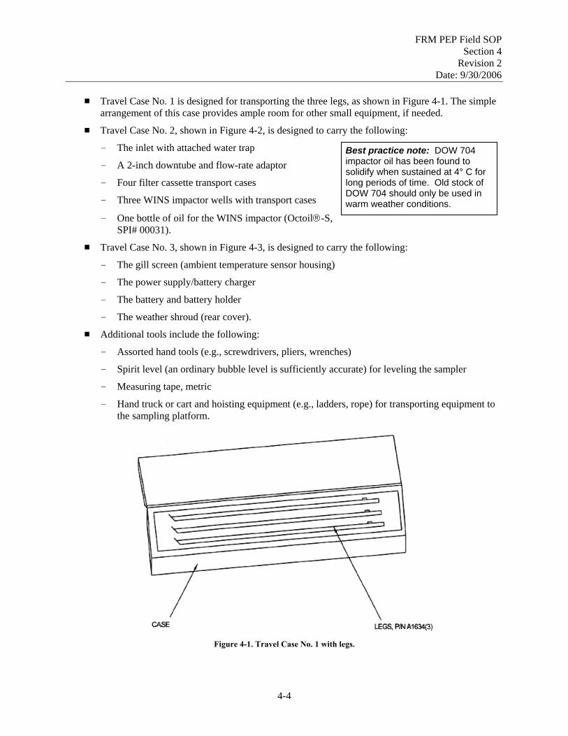
FRM PEP Field SOP Section 4
Revision 2 Date: 9/30/2006
# Travel Case No. 1 is designed for transporting the three legs, as shown in Figure 4-1. The simple
arrangement of this case provides ample room for other small equipment, if needed.
# Travel Case No. 2, shown in Figure 4-2, is designed to carry the following:
- The inlet with attached water trap Best practice note: DOW 704 impactor oil has been found to solidify when sustained at 4° C for long periods of time. Old stock of DOW 704 should only be used in warm weather conditions.
- A 2-inch downtube and flow-rate adaptor
- Four filter cassette transport cases
- Three WINS impactor wells with transport cases
- One bottle of oil for the WINS impactor (Octoil®-S, SPI# 00031).
# Travel Case No. 3, shown in Figure 4-3, is designed to carry the following:
- The gill screen (ambient temperature sensor housing)
- The power supply/battery charger
- The battery and battery holder
- The weather shroud (rear cover).
# Additional tools include the following:
- Assorted hand tools (e.g., screwdrivers, pliers, wrenches)
- Spirit level (an ordinary bubble level is sufficiently accurate) for leveling the sampler
- Measuring tape, metric
- Hand truck or cart and hoisting equipment (e.g., ladders, rope) for transporting equipment to the sampling platform.
Figure 4-1. Travel Case No. 1 with legs.
4-4

FRM PEP Field SOP Section 4
Revision 2 Date: 9/30/2006
Figure 4-2. Travel Case No. 2 for inlet and accessories.
4-5

FRM PEP Field SOP Section 4
Revision 2 Date: 9/30/2006
Figure 4-3. Travel Case No. 3 for gill screen and accessories.
4-6

FRM PEP Field SOP Section 4
Revision 2 Date: 9/30/2006
4.1.7 Procedures
4.1.7.1 Transportation of Equipment to the Site
The portable FRM samplers will normally be transported with the transfer standards and other tools and equipment. Use the main unit and the three travel cases to transport the portable samplers safely and securely and to minimize the effects of rough handling. The PEP encourages the use of ground transportation to sites due to the nature of the sampling equipment, the possibility of rough handling during air transportation, and the cost of shipping. Observe the following guidelines in transporting equipment for the PEP:
# Prior to leaving, consider the number of sites to be visited and take an inventory of the field equipment to
- Determine how many portable samplers will be required for the trip. Take at least one additional portable sampler as a spare. Inventory each travel case to ensure all parts are present and in acceptable condition for use.
- Ensure that there are sufficient filter cassettes for each routine, field blank, and collocated sample planned for the trip. Pack extra filter cassettes in case of damage or contamination.
- Ensure there are enough field transport containers, ice substitutes, max/min thermometers, and preprinted express shipping labels for each audit in the trip.
# Place the equipment into the vehicle and secure it to minimize movement of the main unit and the filter cassettes. Ideally, the sampling unit should be placed face-down in the vehicle to minimize movement.
# Park vehicle at least 100 ft from and downwind of the sampling location.
4.1.7.2 Transportation of Equipment to the Sampling Platform, Siting and Placement
Upon arriving at the sampling site
1. Visit the actual location on the sampling platform where the portable sampler will be set-up. The reporting organization representative should indicate this location or it should have been marked in advance.
2. Place the PEP sampler to meet the following siting criteria:
- The PE sampler must have unobstructed air flow for a minimum of 1 meter in all directions.
- The sampler inlet will be placed at a height of 2 to 15 meters above ground level (2–7 meters if the routine sampler is designated as a micro-scale sampler).
- If the PE sampler is collocated with any other particulate matter sampler, the horizontal spacing between sampler inlets must be greater than 1 meter for other PM2.5 samplers and greater than 2 meters for total suspended particulate (TSP) and PM10 high-volume samplers. All samplers must be within 4 meters of each other.
- In cases where several samplers are on site and all collocation criteria can not be met, ensure that the PE sampler is appropriately spaced from the primary FRM sampler.
- The sampler inlet must be level.
4-7

FRM PEP Field SOP Section 4
Revision 2 Date: 9/30/2006
- Vertical distance between the PE sampler inlet and the audited site sampler inlet must be less
than or equal to 1 meter.
3. If the location designated for the PE sampler does not appear to conform to the siting requirements, document this in the Field Notebook and follow-up with official communications to the site contact and the EPA COR (via telephone). Notes should also be recorded on the FDS.
4. If the siting problem is rectified, document this in the Field Notebook and notify the COR. If the siting problem is not rectified, do not proceed with the sampling event unless directed by the COR.
5. Once the location is set, determine the best method of transporting the equipment to the site.
6. Transport the sampling equipment and verification device(s) in their traveling cases to the sampling platform. (The main sampler module may be transported to the platform without its traveling case.)
7. Under rainy conditions, it may be preferable to install the battery while in a dry location (e.g., the van or hotel room) before transporting the equipment to the sampling platform. If this is the case, take extra precautions by using a hand-truck because of the additional weight. Alternately, the FS may decide to operate the sampler without the battery installed.
8. Transport all verification equipment to the sampling platform to give this equipment an opportunity to equilibrate to ambient conditions (~ 1 hour).
4.1.8 References
1. BGI Inc.1998. PQ200 Air Sampler Instruction Manual.
2. BGI Inc.1998. PQ200A Audit Sampler, Appendix H in PQ200 Air Sampler Instruction Manual. August.
3. U.S. EPA (Environmental Protection Agency). 1998. Monitoring PM2.5 in Ambient Air Using Designated Reference or Class I Equivalent Methods, Section 2.12 in Quality Assurance Handbook for Air Pollution Measurement Systems, Volume II, Part II. April draft.
4-8

FRM PEP Field SOP Section 5
Revision 2 Date: 9/30/2006
Field Standard Operating Procedures
for the PM2.5 FRM Performance Evaluation Program
Section 5
Sampler Setup and Performance Verifications
SOP: PEPF-5
Name: Printed Signature Date
Dennis Crumpler
Contents Section Page
5.1 Sampler Assembly ..............................................................................................................5-4 5.1.1 Scope and Applicability................................................................................................5-4 5.1.2 Summary of Method.....................................................................................................5-4 5.1.3 Definitions ....................................................................................................................5-4 5.1.4 Personnel Qualifications...............................................................................................5-4 5.1.5 Health and Safety Warnings .........................................................................................5-4 5.1.6 Cautions........................................................................................................................5-5 5.1.7 Equipment and Supplies ...............................................................................................5-5 5.1.8 Procedure ......................................................................................................................5-6 5.1.9 References ..................................................................................................................5-11
5.2 Leak Check Procedures.....................................................................................................5-16 5.2.1 Scope and Applicability..............................................................................................5-16 5.2.2 Summary of Method...................................................................................................5-16 5.2.3 Definitions ..................................................................................................................5-16 5.2.4 Personnel Qualifications.............................................................................................5-16 5.2.5 Cautions......................................................................................................................5-16 5.2.6 Equipment and Supplies .............................................................................................5-17 5.2.7 Procedure ....................................................................................................................5-17 5.2.8 References ..................................................................................................................5-20
5.3 Flow Rate Verification......................................................................................................5-21 5.3.1 Scope and Applicability..............................................................................................5-21 5.3.2 Summary of Method...................................................................................................5-21
5-1

FRM PEP Field SOP Section 5
Revision 2 Date: 9/30/2006
5.3.3 Definitions ..................................................................................................................5-21 5.3.4 Personnel Qualifications.............................................................................................5-21 5.3.5 Cautions......................................................................................................................5-21 5.3.6 Equipment and Supplies .............................................................................................5-22 5.3.7 Procedure ....................................................................................................................5-22 5.3.8 References ..................................................................................................................5-24
5.4 Barometric Pressure Verification ......................................................................................5-25 5.4.1 Scope and Applicability..............................................................................................5-25 5.4.2 Summary of Method...................................................................................................5-25 5.4.3 Definitions ..................................................................................................................5-25 5.4.4 Personnel Qualifications.............................................................................................5-25 5.4.5 Cautions......................................................................................................................5-25 5.4.6 Equipment and Supplies .............................................................................................5-26 5.4.7 Procedure ....................................................................................................................5-26 5.4.8 References ..................................................................................................................5-27
5.5 Temperature Verification ..................................................................................................5-28 5.5.1 Scope and Applicability..............................................................................................5-28 5.5.2 Summary of Method...................................................................................................5-28 5.5.3 Definitions ..................................................................................................................5-28 5.5.4 Personnel Qualifications.............................................................................................5-28 5.5.5 Cautions......................................................................................................................5-28 5.5.6 Equipment and Supplies .............................................................................................5-28 5.5.7 Procedure ....................................................................................................................5-29 5.5.8 References ..................................................................................................................5-30
5.6 Preparing to Sample ..........................................................................................................5-31 5.6.1 Scope and Applicability..............................................................................................5-31 5.6.2 Summary of Method...................................................................................................5-31 5.6.3 Definitions ..................................................................................................................5-31 5.6.4 Personnel Qualifications.............................................................................................5-31 5.6.5 Procedure ....................................................................................................................5-31 5.6.6 References ..................................................................................................................5-33
Figures Page Figure 5-1. BGI PQ200A sampler, legs installed. .....................................................................................5-6 Figure 5-2. Back of main unit. ...................................................................................................................5-7 Figure 5-3. Travel Case No. 2 for inlet and accessories. .........................................................................5-12 Figure 5-4. Travel Case No. 3 for gill screen and accessories. ................................................................5-13 Figure 5-5. Exploded view of inlet unit. ..................................................................................................5-14 Figure 5-6. BGI PQ200A sampler with filer chamber assembly open. ...................................................5-15 Figure 5-7. BGI PQ200A sampler with filter chamber assembly closed.................................................5-15 Figure 5-8. Flow rate adapter...................................................................................................................5-19
5-2

FRM PEP Field SOP Section 5
Revision 2 Date: 9/30/2006
Forms Page FDS PM2.5 Federal Reference Method Performance Evaluation Program Field Data Sheet
for BGI PQ200A ..................................................................................................................5-37
5-3
FRM PEP Field SOP Section 5
Revision 2 Date: 9/30/2006
5.1 Sampler Assembly 5.1.1 Scope and Applicability
This section describes the routine procedures for assembling the BGI PQ200A sampler. This section contains material specific for the BGI PQ200A Air Sampler and may not be applicable to other sampler makes and models.
5.1.2 Summary of Method
Assembling the BGI PQ200A sampler involves attaching the sampler’s legs and anchoring the sampler firmly to the ground; attaching the sampler’s temperature probe; leveling the sampler; checking the condition of the transport cassette; powering the sampler unit; and setting the sample date and time.
5.1.3 Definitions
Appendix A contains a glossary of terms used in the PEP.
5.1.4 Personnel Qualifications
Personnel who conduct the FRM PEs must have attended an initial training course, which includes lectures, demonstrations, hands-on practice, a written exam for which a passing score of 80% is achieved, and a hands-on practical training examination. Annual recertification requirements include a written and hands-on practical training examination. A technical systems audit (TSA) of the FS may replace the hands-on practical examination for annual recertification.
5.1.5 Health and Safety Warnings
# Safety is the priority. The FS may use his or her discretion if an unusual situation arises associated with assembling the monitor; an example being the installation of a battery during inclement (wet) conditions. If the potential exists for the battery to become wet and slippery and the electronics could get wet, the FS can decide if it is safer to install the battery in the van, prior to sampler assembly.
# Always be careful when attaching the AC power connection. Do not attempt to connect the main power if any power connectors or wires appear cracked, frayed, or wet. Do not immerse power cords in water or other liquids.
# Avoid unnecessarily opening the control panel or touching internal electrical components while the AC power is applied. Be very careful when it is necessary to make adjustments while the power is on, such as when adjustments are made on the circuit boards during some calibration procedures.
# Make sure that the electrical outlet used with the PEP equipment is connected through a Ground Fault Circuit Interrupter (GFCI) device. If not, a portable GFCI device may be used.
Best practice note: Where permanent GFCls are not practical, portable GFCls may be used. One type contains the GFCI circuitry in a plastic encio-sure with plug blades in the back and receptacle slots in the front. It can be plugged into a receptacle, then the electrical product is plugged into the GFCI. Another type of portable GFCI is an extension cord combined with a GFCI. It adds flexibility in using receptacles that are not protected by GFCls.
5-4

FRM PEP Field SOP Section 5
Revision 2 Date: 9/30/2006
5.1.6 Cautions
# When attaching the legs to the sampler’s main body, do not allow the unit to become unbalanced and fall. If necessary, ask another person for assistance in attaching the legs.
# Be careful to ensure that the battery or studs do not come in contact with the printed circuit board because physical damage may occur! Secure the battery by threading the two wing nuts onto the studs. Connect the color-coded wires to the color-coded terminals on the battery (red on red, black on black). Connect and disconnect the red (“hot”) wire first.
# The FS must properly install and maintain the sampler to prevent damage and contamination. Be particularly attentive to maintenance of the pump, ensuring the soundness of electrical and pneumatic connections that will be repeatedly assembled and disassembled.
# Check the numerous O-rings periodically. Clean and lubricate their surfaces as required for ease of assembly and the maintenance of leak-free seals. Replace O-rings that are split, brittle, or cracked. Use only O-rings specified for this equipment.
# When the sampler is dismantled, be sure to remove any debris adhering to the base or legs before storing them for transport. To minimize contamination, always pack the base or leg portion of the sampler apart from the sampler collection module. If inadvertently transferred to the sample collection filter enclosure, a small particle of dust or pollen will alter the sample weight dramatically.
# Care must be taken during handling not to crack or break the water collector jar attached to the side of the inlet. To minimize the chance of accidental breakage, the glass water collector jar may be replaced with a plastic jar or wrapped with insulating tape to lessen the shock of rough handling.
# The operating area for the FS may include more than one time zone. The FS needs to be aware of time zone changes and set up monitors based on local standard time.
5.1.7 Equipment and Supplies
# BGI PQ200A air sampler and instruction manual # 25-ft extension cord # Expansion device (power strip) # Bubble leveling device # Shims for leveling instrument # Assorted tools, including screwdrivers, pliers, etc. # Flashlight for inspection of various sampler assemblies # Pen or pencil for marking the sampler for reassembly # Soft brush # Lint-free wipes # Alcohol wipes # Spare O-rings and vacuum grease # Diffusion oil # Dropper for diffusion oil.
5-5

FRM PEP Field SOP Section 5
Revision 2 Date: 9/30/2006
5.1.8 Procedure
This procedure applies to placement and installation at the field site; however, it is also applicable for indoor set-up when testing the sampler before field use.
NOTE: Prior to assembling the sampler, the FS should set the verification equipment in a protected and shaded outdoor location to allow for equilibration.
5.1.8.1 Assembling the Legs and Anchoring the Sampler (one-man assembly)
NOTE: To avoid possible personal injury and sampler damage, care should be used when assembling the sampler legs and leveling the sampler. If necessary, ask for help from another person. This procedure is easy to do, but difficult to describe in text. The best way to understand this procedure is by working with an experienced person to set up a sampler.
1. Lay the portable sampler equipment as close to the actual sampling location as possible.
2. Lay the sampler main unit on Side 1 or 3 (see Figure 5-1).
Side 1
Side 3
Figure 5-1. BGI PQ200A sampler, legs installed.
3. Attach two legs to the unit at the two accessible points of attachment on the underside of the
sampler. The legs are identical and interchangeable. Make sure the connectors are seated properly and that the legs are securely attached (the legs will make a “click” upon secure attachment).
4. Place the third leg in a convenient place to allow for easy access.
5. Securely hold the main unit and slowly “walk” the unit and the two legs into an upright position.
5-6
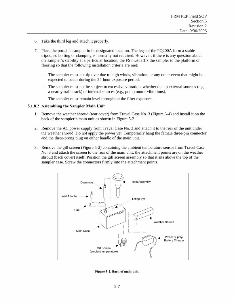
FRM PEP Field SOP Section 5
Revision 2 Date: 9/30/2006
1.
2.
3.
6. Take the third leg and attach it properly.
7. Place the portable sampler in its designated location. The legs of the PQ200A form a stable tripod, so bolting or clamping is normally not required. However, if there is any question about the sampler’s stability at a particular location, the FS must affix the sampler to the platform or flooring so that the following installation criteria are met:
- The sampler must not tip over due to high winds, vibration, or any other event that might be expected to occur during the 24-hour exposure period.
- The sampler must not be subject to excessive vibration, whether due to external sources (e.g., a nearby train track) or internal sources (e.g., pump motor vibrations).
- The sampler must remain level throughout the filter exposure. 5.1.8.2 Assembling the Sampler Main Unit
Remove the weather shroud (rear cover) from Travel Case No. 3 (Figure 5-4) and install it on the back of the sampler’s main unit as shown in Figure 5-2.
Remove the AC power supply from Travel Case No. 3 and attach it to the rear of the unit under the weather shroud. Do not apply the power yet. Temporarily hang the female three-pin connector and the three-prong plug on either handle of the main unit.
Remove the gill screen (Figure 5-2) containing the ambient temperature sensor from Travel Case No. 3 and attach the screen to the rear of the main unit; the attachment points are on the weather shroud (back cover) itself. Position the gill screen assembly so that it sits above the top of the sampler case. Screw the connectors firmly into the attachment points.
Figure 5-2. Back of main unit.
5-7

FRM PEP Field SOP Section 5
Revision 2 Date: 9/30/2006
4.
5.
6.
7.
8.
9.
10.
Open the front door on the PQ200A sampler and feed both female three-pin power connectors through the hole underneath the sampler case.
While the front door is open, remove the two thumb nuts holding the instrument panel. Swing the panel forward on its hinge.
Remove the wing nuts from the battery-securing studs and remove the metal restraining bar before inserting the battery. Lift the battery and holder from the travel case and install it at the rear of the instrument panel compartment. CAUTION: Be careful to ensure that the battery does not come in contact with the printed circuit board because physical damage may occur! Secure the battery by using the metal restraining bar and threading the two wing nuts onto the studs.
Connect the color-coded wires to the color-coded terminals on the battery (red on red; black on black). Connect and disconnect the red (“hot”) wire first.
Check that the connectors are seated properly on the circuit board. It is possible for these connections to loosen during transport or while opening the front panel.
Proper connection of the battery can be confirmed by powering up the BGI unit prior to plugging in the AC adaptor. If the unit powers up, the battery is properly connected. If the unit does not power up, recheck the battery connections. If it still does not power up, the battery should be replaced. Warning: Conducting the sample run without a reasonably charged battery, poses a risk of an incomplete sample run should there be a power failure.
Close the panel, making sure all wires and cables are out of the way, and reattach the two thumb nuts.
5.1.8.3 Leveling the Sampler
1. Inspect the sampler to ensure that the inlet is not misaligned due to an improperly mounted downtube. The downtube should be perpendicular to the top of the sampler’s main case. Make any necessary adjustments to the downtube mountings.
2. Adjust the PE sampler so that bubble level indicates that the top surface of the size-selective inlet is horizontal. Conduct the final leveling of the unit only after the major installation tasks described above have been completed. (Repeat the leveling process if any subsequent activities cause the sampler to shift.)
3. The sampler’s horizontal angle can be adjusted by placing thin shims of wood or other solid material under the legs. Observe safety precautions; it may require two people to safely place the shims. Verify that the sampler remains secure after shims are in place.
5.1.8.4 Inspecting the Transport Cassette
NOTE: Prior to working with cassettes, clean your hands with alcohol wipes or clean water and allow them to air dry.
5-8

FRM PEP Field SOP Section 5
Revision 2 Date: 9/30/2006
1. The portable sampler is shipped and will always be transported with a transport cassette in place;
however, the sampler should never be transported when loaded with actual filter cassettes that are intended for sampling.
2. Remove the transport cassette and inspect for damage.
3. Inspect the filter housing (lower portion of filter chamber assembly) for obvious missing pieces or damage.
4. Confirm the presence and condition of the O-rings inside the upper and lower filter housings where the O-rings contact the filter cassette. Ensure that the interior of the housing is clean and free of debris. Place the transport cassette back into its sampling position for use during verifications. If the transport cassette or the filter it contains has been damaged during transport, use a spare transport filter cassette for the verifications. The sampling event filter should not be used for the flow check due to the risk of damaging or contaminating it prior to the sampling event.
5. Close the filter chamber assembly by slowly rotating the handle clockwise 3/4 of a turn (Figure 5-7) until the cam follower clicks into the indent in the cam. Watch the filter cassette and WINS impactor to ensure that they are seated properly and that the filter chamber assembly closes securely. If necessary to avoid air leakage, the compression between the upper and lower housings of the WINS assembly can be adjusted using the knurled ring.
5.1.8.5 Powering the Unit
Connect the power as follows, depending on whether or not AC power is available:
1. For AC operation, plug the AC power supply unit into a 110/120-volt grounded outlet.
2. When AC power is not available and the COR has approved the use of battery power, the unit may be operated from the battery backup system. When fully charged, battery power is sufficient to operate the PQ200A for 24 hours in all but the most extreme conditions (e.g., high particle loads, cold weather conditions). NOTE: When operating from battery power, the control screen dims and it may be necessary to press the red LIGHT button to view the screen.
3. If there is only one outlet available, use of an expansion device (i.e., power strip) is allowable. However, the state/local operator must handle their own equipment. Be sure that the expansion device is capable of handling the same level of current as the circuit. A surge of power at startup can cause problems with the sampling device.
5-9

FRM PEP Field SOP Section 5
Revision 2 Date: 9/30/2006
4. Press the ON/OFF button on the PQ200A. The screen will light up and display the following
message:
PQ200 Air Sampling System (c)Copyright 1997 BGI Incorporated All Rights Reserved Version: X.XX Serial Number: XXXX
The X’s will appear as numbers indicating the actual version number and serial number.
5. After a few seconds, the Main screen will appear. The Main screen always displays the ambient barometric pressure, ambient and filter temperatures, date, time, power source, and any flags that may have occurred. Any error or status messages will also appear on the screen. For example:
READY FOR NEW RUN! 746mmHg A28.0EC F27.5 EC
[DC IN] 99999 2001 04jul
(MENU) 14:53
WARNING: If data was not downloaded from a previous run, a message to this effect will be displayed on this screen. The FS should download the data to prevent it from being lost. If the data is not downloaded, it will be automatically deleted when the new sampling event begins.
6. Confirm the accuracy of the date and time displayed on the screen. The time should reflect
local standard time for the site. Note that the PQ200A operates exclusively on 24-hr military time.
7. Press the blank (MENU) button on the PQ200A control panel to enter the Main menu. If necessary, follow the steps below to set the proper date and time.
5.1.8.6 Setting Date and Time
NOTE: The operating area for the FS may include more than one time zone. The FS needs to be aware of time zone changes, set samplers up based on the local standard time, and ensure that PEP sampler’s start and stop times match those of the audited sampler.
After the sampler has been successfully installed and powered-up, the date and time should be checked and, if necessary, adjusted to local standard time. All PEP samplers should be synchronized within 1 minute of a known time standard. Use the following procedure to set or adjust the BGI PQ200A’s date and time:
1. From the Main menu, use the arrow keys until * Set-Ups and Download flashes. Press SELECT to enter the Set-ups and Download menu.
2. From the Set-Ups and Download menu, with * More Selections flashing, press SELECT. Then press the down arrow button until * Set Date and Time flashes. Press SELECT.
5-10
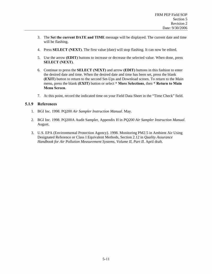
FRM PEP Field SOP Section 5
Revision 2 Date: 9/30/2006
3. The Set the current DATE and TIME message will be displayed. The current date and time
will be flashing.
4. Press SELECT (NEXT). The first value (date) will stop flashing. It can now be edited.
5. Use the arrow (EDIT) buttons to increase or decrease the selected value. When done, press SELECT (NEXT).
6. Continue to press the SELECT (NEXT) and arrow (EDIT) buttons in this fashion to enter the desired date and time. When the desired date and time has been set, press the blank (EXIT) button to return to the second Set-Ups and Download screen. To return to the Main menu, press the blank (EXIT) button or select * More Selections, then * Return to Main Menu Screen.
7. At this point, record the indicated time on your Field Data Sheet in the “Time Check” field.
5.1.9 References
1. BGI Inc. 1998. PQ200 Air Sampler Instruction Manual. May.
2. BGI Inc. 1998. PQ200A Audit Sampler, Appendix H in PQ200 Air Sampler Instruction Manual. August.
3. U.S. EPA (Environmental Protection Agency). 1998. Monitoring PM2.5 in Ambient Air Using Designated Reference or Class I Equivalent Methods, Section 2.12 in Quality Assurance Handbook for Air Pollution Measurement Systems, Volume II, Part II. April draft.
5-11

FRM PEP Field SOP Section 5
Revision 2 Date: 9/30/2006
Figure 5-3. Travel Case No. 2 for inlet and accessories.
5-12

FRM PEP Field SOP Section 5
Revision 2 Date: 9/30/2006
Figure 5-4. Travel Case No. 3 for gill screen and accessories.
5-13

FRM PEP Field SOP Section 5
Revision 2 Date: 9/30/2006
146
147
148
149
150
151
152
153
154
155 156
157
158159
Part Number Description Part Number Description
146 #6-32 x 3/8” Philips pan head screw 153 inlet tube
147 inlet top 154 1/4 x 3/8 NPT adapter
148 spacer 155 1/4 NPT nipple
149 screen 156 jar top
150 inlet sub top 157 1/4 NPT plug
151 inlet body 158 glass jar
152 O-ring 159 O-ring
Figure 5-5. Exploded view of inlet unit.
5-14

FRM PEP Field SOP Section 5
Revision 2 Date: 9/30/2006
Figure 5-6. BGI PQ200A sampler with filer chamber assembly open.
Figure 5-7. BGI PQ200A sampler with filter chamber assembly closed.
5-15

FRM PEP Field SOP Section 5
Revision 2 Date: 9/30/2006
5.2 Leak Check Procedures
5.2.1 Scope and Applicability
This section applies to performing the mandatory external leak check procedure for the FRM PEP. Each portable PM2.5 PEP sampler will be checked for leaks before the flow rate verification. The leak check procedure verifies the integrity of the WINS and air handling tubes and fittings up to and including the FRM’s flow rate measurement sensor.
NOTE: This section applies only to the BGI PQ200A air sampler. Each manufacturer’s equipment is somewhat different, so consult the operations manual for specific instructions applicable to a particular FRM sampler.
5.2.2 Summary of Method
The leak check procedure is used to verify that the air handling system in the sampler is adequately free from leakage that could cause filtration artifacts or the incorrect measurement of flow rate. The BGI PQ200A sampler automatically determines leakage by pulling a vacuum on the internal air volume of the fully assembled sampler, sealing the volume by closing valves, and monitoring the internal pressure change for a period of 2 minutes. (NOTE: Older software may perform leak checks for 10 minutes.) If the internal pressure increases too rapidly, a leak is indicated, and troubleshooting procedures must be followed to stop the leak. The leak check must be successful before flow rate verification can be performed. An internal leak check procedure to assess leakage within the filter assembly is also described as a troubleshooting procedure (Section 5.2.7.3).
5.2.3 Definitions
Appendix A contains a glossary of terms used in the PEP.
5.2.4 Personnel Qualifications
Personnel who conduct the FRM PEs must have attended an initial training course, which includes lectures, demonstrations, hands-on practice, a written exam for which a passing score of 80% is achieved, and a hands-on practical training examination. Annual recertification requirements include a written and hands-on practical training examination. A technical systems audit (TSA) of the FS may replace the hands-on practical examination for annual recertification.
5.2.5 Cautions
1. At the conclusion of the leak check, it is very important to open the flow rate adapter valve slowly to avoid generation of rapidly moving air currents, which could spread impactor oil and other contaminants throughout the system.
2. Ensure that the filter cassette is properly seated and the cam is properly closed to create a good seal.
3. Do not connect any other device to the flow rate adapter when conducting this procedure.
5-16

FRM PEP Field SOP Section 5
Revision 2 Date: 9/30/2006
5.2.6 Equipment and Supplies
# BGI PQ200A sampler
# Clean filter in transport cassette, designated as a leak check or flow check filter. This filter is not to be used for sampling and may be used repeatedly for leak checks, flow rate verifications, and multipoint flow rate calibrations. When this filter becomes soiled or damaged, it should be discarded; however, the cassette should be retained.
# Flow rate adapter with valve to close flow (see Figure 5-8)
# Impermeable disk for internal leak check (stainless steel or plastic film)
# Field Data Sheet.
5.2.7 Procedure
5.2.7.1 Conducting an External Leak Check
1. Insert a leak check filter/transport cassette into the filter holder. Label or mark the leak check/transport cassette to ensure it will not be mistaken as a sample filter. Also be certain an empty transport WINS impactor well (without filter or oil) is present. Close the assembly by rotating the cam clockwise until an audible “click” is heard.
2. Remove the size-selective inlet from the downtube and place the flow rate adapter on the top of the downtube. Close the valve on the adapter to prevent air flow.
3. From the Main menu of the BGI PQ200A, use the arrow keys until * Test and Calibration Menu flashes. Press SELECT to enter the Test menu.
4. From the Test menu, press the down arrow until * Leak Test flashes. Press SELECT. The PQ200 LEAK TEST: In Progress! screen will be displayed. Ensure that the flow path is sealed (i.e., the valve on the flow rate adapter is closed and the cam is rotated fully clockwise to seal the WINS and filter assembly securely in place) and press SELECT to begin evacuating the system.
5. The PQ200A will automatically evaluate the performance of the system and report whether the system passed or failed the leak test. The pump will come on and begin to pull a vacuum on the system. When a vacuum in excess of 75 cm water is attained, the pump will turn off, and a timer will begin to count for 2 minutes. The initial (locked) pressure is displayed on the left side of the screen. This pressure reading will be a number in excess of 75 cm of the water column. Enter the initial pressure in the place provided on the Field Data Sheet (Appendix C).
NOTE: Older software (firmware) versions performed leak checks for 10 minutes.
6. In order to pass the test, the actively displayed differential system pressure (shown on the right side of the screen as “SP”) must not drop by more than 5 cm water during the 2-minute time interval (or 10 cm water if using a 10-minute time interval). This is equivalent to the 80 mL/min acceptance criteria stated in related QA documents. At the end of the 2-minute period, the BGI PQ200A panel display will indicate whether the sampler passed or failed the
5-17

FRM PEP Field SOP Section 5
Revision 2 Date: 9/30/2006
leak test. Record the final pressure on the Field Data Sheet. Indicate whether the leak check was successful by circling “Yes” or “No.”
7. If the sampler passed the leak test, slowly release the vacuum on the system by slowly opening the valve on the flow rate adapter. Remove the flow rate adapter and place a black cover cap on the downtube. Proceed with the other verification checks.
8. If the sampler failed the leak test, double check to make sure flow rate adapter and filter chamber assembly are closed. Conduct a second external leak check. If the sampler fails a second leak test, investigate and correct any malfunctions as described in Section 5.2.7.2. Release the vacuum on the system by slowly opening the valve on the flow rate adapter.
NOTE: The leak test must be successful prior to performing the flow rate verification or using sampler to acquire a PE sample.
5.2.7.2 Troubleshooting When the Leak Check Fails
The following troubleshooting procedures should be used when a sampler does not pass the leak check after several tries:
1. Slowly release the vacuum on the system by slowly opening the valve on the flow rate adapter.
2. Make sure the flow rate adapter is securely seated on the downtube and that the valve is completely closed.
3. Make sure the filter chamber assembly (with unloaded WINS) is securely closed. If it is not, close it tightly. It may be necessary to make minor adjustments to the cam follower’s position using the cam follower adjustment nut so the cam, when in the “closed” position, holds the WINS and filter assembly together more tightly.
4. Make sure the filter cassette was securely closed and placed in the filter housing during the leak test.
5. Visually inspect tubing for cracks or loose connections.
6. Visually examine the O-rings in the flow rate adapter, WINS, and filter holder for cracks, deformation, or improper seating.
7. If no reason for leakage is readily apparent, increase the compression between the upper and lower housings of the WINS assembly by turning the knurled ring to slightly adjust the length of the cam follower. The knurled ring is located just above the cam follower.
8. Perform another external leak check. If the sampler fails again, it may be helpful to perform an internal leak check. This test allows the FS to determine if the leak(s) occur before or after the filter cassette. Internal leak checks are described in Section 5.2.7.3, below.
5-18

FRM PEP Field SOP Section 5
Revision 2 Date: 9/30/2006
5.2.7.3 Conducting an Internal Leak Check
Conduct the internal leak check as follows:
1. Release the vacuum on the system by slowly opening the valve on the flow rate adapter. Keep this valve open.
2. Insert an impermeable disk for internal leak check (stainless steel or plastic film the same size, shape, and rim thickness of the normally used Teflon™ filter). This disk effectively seals and isolates the air space from beneath the solid disk to the solenoid valve before the pump assembly.
3. Perform the internal leak check. For the BGI PQ200A, the check sequence is the same as described above for the external leak check except that the flow rate device valve is open to the atmosphere.
4. If no leakage is present, the sampler has passed the internal leak check, and the external leak, if there was one, must be located somewhere above the filter. If leakage is present, confine the search for the leak to the area below the filter disk.
5. If the problem was discovered and rectified, perform the external leak check again (see Section 5.2.7.1).
If the problem cannot be located and the sampler continues to fail the leak checks, the sampler requires further troubleshooting and maintenance and must not be used for the PE.
Figure 5-8. Flow rate adapter.
5-19

FRM PEP Field SOP Section 5
Revision 2 Date: 9/30/2006
5.2.8 References
1. BGI Inc. 1998. PQ200 Air Sampler Instruction Manual. May.
2. BGI Inc. 1998. PQ200A Audit Sampler, Appendix H in PQ200 Air Sampler Instruction Manual. August.
3. U.S. EPA (Environmental Protection Agency). 1998. Monitoring PM2.5 in Ambient Air Using Designated Reference or Class I Equivalent Methods, Section 2.12 in Quality Assurance Handbook for Air Pollution Measurement Systems, Volume II, Part II. April.
5-20

FRM PEP Field SOP Section 5
Revision 2 Date: 9/30/2006
5.3 Flow Rate Verification 5.3.1 Scope and Applicability
NOTE: The following information is applicable to the BGI Model PQ200A portable FRM sampler and the BGI Delta-Cal verification device. Specific information herein may not be applicable to other makes and models of equipment. (Refer to Appendix E for directions on using an alternate verification devices.)
Each reference or Class I equivalent PM2.5 sampler includes a specially designed sample air inlet, a size-fractionating impactor, and a sample flow rate control system. The particle size discrimination characteristics of both the inlet and the impactor are critically dependent on specific internal air velocities; a change in velocity will result in a change in the nominal particle size collected. These velocities are determined by the actual volumetric flow rate of the sampler.
In addition, the total volume of air sampled is determined from the measured volumetric flow rate and the sampling time. The mass concentration of PM2.5 in the ambient air is computed as the total mass of collected particles in the PM2.5 size range divided by the total volume of air sampled.
Therefore, in order to control the size-fractionating cutpoints and to measure the total volume correctly, the sampler’s flow rate must be maintained at a constant value that is within +4% of the design flow rate of 16.67 L/min. The flow rate of the portable FRM sampler must be verified at each site before the PE samples are taken.
5.3.2 Summary of Method
A single-point verification of the sampler flow rate is performed prior to each use of the BGI sampler in a PE. If the verification check is outside the tolerance of +4% of the indicated reading or +5% of the design flow rate (16.67 Lpm) and no reason can be found for the discrepancy, a multipoint verification/calibration of the sampler is performed (see SOP PEPF-10, Multipoint Verifications and Calibrations).
5.3.3 Definitions
Appendix A contains a glossary of terms used in the PEP.
5.3.4 Personnel Qualifications
Personnel who conduct the FRM PEs must have attended an initial training course, which includes lectures, demonstrations, hands-on practice, a written exam for which a passing score of 80% is achieved, and a hands-on practical training examination. Annual recertification requirements include a written and hands-on practical training examination. A technical systems audit (TSA) of the FS may replace the hands-on practical examination for annual recertification.
5.3.5 Cautions
# Do not operate the sampler without the verification/transport filter cassette installed. The verification/transport filter cassette should contain a clean Teflon™ filter that is free of holes, wrinkles, debris, or other defects.
5-21

FRM PEP Field SOP Section 5
Revision 2 Date: 9/30/2006
# Verification of the sampler’s flow rate measurement system must be in units of the actual ambient
volumetric flow rate. Do not use “mass flow rate” or “flow rate at standard conditions.”
# Verify that the flow transfer standard is properly seated on the downtube. The O-rings on the FTS must face downward.
5.3.6 Equipment and Supplies
# NIST-traceable BGI Delta-Cal verification device
# Isopropyl alcohol
# Lint-free swabs
# Hand calculator (scientific)
# Field Data Sheet
# Time piece
5.3.7 Procedure
The operating flow rate of 16.67 L/min is verified before each PE. If the verification result is outside the required +4% tolerance of the indicated flow or +5% of the design flow rate, a multipoint verification/calibration at three different flow rates may be required. The one-point verification must be repeated after any three-point calibration to ensure the sampler operates properly at the design flow rate of 16.67 L/min. In the field, only a one-point verification/calibration should be performed.
Note: Experience has taught us that if, after recalibration, the one-point verification is greater than 4% of the transfer standard, the calibration is drifting. There is likely a mechanical issue with the BGI pump/motor or electronics which needs to be serviced.
5.3.7.1 Flow Rate Verification using the Delta-Cal
Perform the sampler leak, temperature, and barometric pressure verification procedures, and take any corrective actions necessary to meet the acceptance criteria before performing this procedure. Ensure that the Delta-Cal (already on the downtube) is properly seated on the downtube and is equilibrated to ambient conditions.
1. Install a clean flow rate test/transport filter cassette in the filter cassette holder. This filter cassette should not be used for sampling, as a blank, or as a QC sample. The flow rate test/transport filter cassette may be reused at other sites provided that it remains clean and is free from any defects, such as tears, pinholes, or separation from the support ring.
2. From the Main menu of the sampler’s control panel, use the arrow keys until * Test and Calibration Menu flashes. Press SELECT to enter the Test menu.
3. From the Test menu, press the down arrow until * Verify Flow Calibration flashes
4. Press SELECT. The pump will start, and the display screen will read Stabilizing Flow. Watch the display screen as the flow rate increases and stabilizes. The Check Flow Now! screen will then be displayed. Allow at least 2 minutes for stabilization. The flow rate may fluctuate or oscillate. Once the reading is considered stable, observe the high and low values
5-22

FRM PEP Field SOP Section 5
Revision 2 Date: 9/30/2006
of the oscillation and record the mean value flow rate on the Field Data Sheet under “Sampler FR.” NOTE: The flow rate values are in units of volume (liters/minute).
5. Observe the indicated flow rate from the Delta-Cal and record this value in the “Std. FR (calc)” field on the Field Data Sheet.
5.3.7.2 Flow Rate Acceptance Criteria
1. Calculate the offset or error between the flow rate indicated by the sampler readout and the calculated flow rate from the Delta-Cal. The equation for percent difference (PD) is as follows:
( )PDFlow Flow
Flowsampler% =
−×standard
standard100
2. If the calculated flow rate is outside the +4% tolerance with the BGI’s flow rate or if the sample flow rate is outside + 5% agreement with the design flow rate, the FS should ensure that the sampler and the flow rate measurement equipment are operating properly using the following steps:
- Verify that all fittings and air hoses are tight and that there are no tubing kinks or obstructions.
- Verify that the body of the Delta-Cal is properly seated on the downtube to prevent leakage past the O-rings that seal it to the downtube.
- Check that flow has stabilized and ensure that the Delta-Cal has been given enough time to equilibrate to ambient conditions. Read the given flow rate provided by the Delta-Cal and record the value.
- Verify that the WINS impactor and filter holder assemblies are closed completely.
- Visually inspect the sampler and the flow rate measurement equipment. Consider any other factors that might affect the flow rate measurement or the sampler operation.
- After adjustments have been made, repeat the flow rate verification procedure. If the calculated flow rate and/or sample flow rate still do not meet QC criteria, check the temperature and barometric pressure readings because they affect the instrument’s flow rate calibration.
- If the calculated flow rate and/or sample flow rate still do not meet QC criteria, there is most likely a mechanical problem with the sampler. It should be taken to the FS laboratory or sent to the manufacturer for repair. A backup sampler unit is necessary.
3. After all troubleshooting has been completed, indicate the final result of the check on the Field Data Sheet. Indicate whether the verification was acceptable by checking the “Yes” or “No” box under “Verification OK?”
4. Following the verification, disconnect the flow rate standard from the sampler, remove the calibration adapter, and carefully reinstall the sampler’s inlet. Remove the filter/cassette used
5-23
FRM PEP Field SOP Section 5
Revision 2 Date: 9/30/2006
during the verification. If it is time to begin sampling, install a new filter cassette as described in SOP PEPF-6, Section 6.1, Conducting the Filter Exposure.
5.3.8 References
1. BGI Inc. 1998. PQ200A Audit Sampler, Appendix H in PQ200 Air Sampler Instruction Manual. August.
2. BGI Inc. Delta-Cal Instruction Manual.
3. U.S. EPA (Environmental Protection Agency). 1998. Monitoring PM2.5 in Ambient Air Using Designated Reference or Class I Equivalent Methods, Section 2.12 in Quality Assurance Handbook for Air Pollution Measurement Systems, Volume II, Part II. April draft.
4. 40 CFR Part 50, Appendix L, Section 9.2.
5-24

FRM PEP Field SOP Section 5
Revision 2 Date: 9/30/2006
5.4 Barometric Pressure Verification 5.4.1 Scope and Applicability
NOTE: The following information applies only to the BGI Model PQ200A portable FRM sampler and the BGI Delta-Cal verification device. Specific information herein may not be applicable to other makes or models of equipment. (Refer to Appendix E for directions on using alternate verification devices).
This section applies to verifying the barometric pressure measurement system of the BGI PQ200A Portable PM2.5 Sampler. Operations covered in this SOP include routine functional check procedures for the pressure measurement system.
5.4.2 Summary of Method
The BGI PM2.5 sampler has a built-in atmospheric pressure sensor. The sensor’s output is processed to allow control of the sampling flow rate to the design value of 16.7 L/min under actual ambient conditions of temperature and pressure.
To perform a routine verification, the barometric pressure sensor reading is verified at ambient pressure through comparison with the reading from an external standard of known accuracy. If a pressure difference of more than 10 mmHg is observed, a multipoint verification/calibration of the pressure-sensing and display system is required before the FRM sampler may be used to perform an evaluation.
5.4.3 Definitions
Appendix A contains a glossary of terms used in the PEP.
5.4.4 Personnel Qualifications
Personnel who conduct the FRM PEs must have attended an initial training course, which includes lectures, demonstrations, hands-on practice, a written exam for which a passing score of 80% is achieved, and a hands-on practical training examination. Annual recertification requirements include a written and hands-on practical training examination. A technical systems audit (TSA) of the FS may replace the hands-on practical examination for annual recertification.
5.4.5 Cautions
# Protect all types of barometers from mechanical shock and sudden changes in pressure. A barometer subjected to either of these events must be verified by comparing it to a laboratory mercury column barometer (or other NIST-traceable standard). If required, the barometer would either be adjusted, or an offset correction would be established.
# Minimize the vertical and horizontal temperature gradients across the barometer and avoid direct sunlight, drafts, and vibrations.
# Barometers should be allowed some time to adjust to temperature and pressure differences. During transport and assembly of the instrument, transport the barometer to the sampling platform so that it may equilibrate for an hour before use.
5-25

FRM PEP Field SOP Section 5
Revision 2 Date: 9/30/2006
# At high altitudes, verification of barometric pressure may be difficult due to significantly lower
pressure. The FS should use all available information, including state/local FRM barometric pressure readings and/or readings from other samplers. The FS may also check with local airport or weather station. The FS should document all of this extra information on the FDS.
5.4.6 Equipment and Supplies
The following equipment and materials are required for barometric pressure verification checks:
# BGI PQ200A sampler # Field Data Sheet # Portable, NIST-traceable barometer for field barometric pressure verifications (BGI Delta-Cal).
5.4.7 Procedure
5.4.7.1 Field Verification of Barometric Pressure System using the Delta-Cal
The Delta-Cal, like other verification devices, needs equilibrate to ambient conditions before use. Be sure to allow time for the verification equipment to equilibrate to ambient conditions. The PM2.5 PEP sampler’s barometric pressure sensing system is verified by comparing the sampler reading to that of the portable barometer at ambient conditions, as described in the following steps:
1. Unpack, install, and power the sampler at the site as described in SOP PEPF-4, Transportation of the Sampler and Installation at the Site, and in Section 5.1.
2. Unpack the Delta-Cal and place its sensor head, which is an orifice device topped with a gill screen, on the downtube.
3. Switch on the power to the Delta-Cal, which can be plugged in or run off of batteries. (If you are using batteries, be sure that they have enough energy to get good readings.)
4. Record the pressure readings from the sampler (Sampler Pressure) and the Delta-Cal (Std. Pressure) on the Field Data Sheet.
5. If the two readings are within 10 mmHg of each other, the verification of the portable PM2.5 PEP monitor’s pressure sensor is satisfactory.
6. If the deviation is greater than 10 mmHg, check the barometric pressure using a backup verification device. If the results are similar to the primary verification device, then the sampler’s pressure measurement system may be damaged and should be serviced. A multipoint verification/calibration procedure should be performed at a later time (see SOP PEPF-10, Multipoint Verifications and Calibrations). A spare PEP sampler must be installed at the site.
NOTE: There is also a possibility that the check standard, rather than the sampler’s pressure system, is faulty. If possible, check the routine PM2.5 sampler’s barometric pressure. If this reading is within 10 mmHg of the barometric pressure reading on the portable sampler, record the routine PM2.5 sampler’s barometric pressure on the Field Data Sheet and proceed with the audit using the portable sampler. Inform the COR of the problem to see if a replacement portable barometric pressure check
5-26

FRM PEP Field SOP Section 5
Revision 2 Date: 9/30/2006
device (Delta-Cal) is available. Take the faulty check device in for recalibration or repairs as soon as possible.
5.4.8 References
1. BGI Inc. 1998. PQ200 Air Sampler Instruction Manual, “Appendix H - PQ200A Audit Sampler.” August/
2. BGI Inc., Delta-Cal Instruction Manual.
3. U.S. EPA (Environmental Protection Agency). 1998. Monitoring PM2.5 in Ambient Air Using Designated Reference or Class I Equivalent Methods, Section 2.12 in Quality Assurance Handbook for Air Pollution Measurement Systems, Volume II, Part II. April draft.
5-27

FRM PEP Field SOP Section 5
Revision 2 Date: 9/30/2006
5.5 Temperature Verification
5.5.1 Scope and Applicability
This section applies to verifying the temperature measurement system for the PM2.5 PEP sampler. Operations covered in this SOP include verification checks for the two temperature sensors in the BGI PQ200A unit using the BGI Delta-Cal verification device. Specific information herein may not be applicable to other makes and models of equipment. (Refer to Appendix E for directions on using alternate verification devices).
5.5.2 Summary of Method
Ambient and filter temperature sensors are each verified at a single point using an external temperature standard of known, NIST-traceable accuracy. If an excessive difference is observed, a multipoint verification/calibration of the temperature sensor may be required (see SOP PEPF-10, Multipoint Verifications and Calibrations).
5.5.3 Definitions
Appendix A contains a glossary of terms used in the PEP.
5.5.4 Personnel Qualifications
Personnel who conduct the FRM PEs must have attended an initial training course, which includes lectures, demonstrations, hands-on practice, a written exam for which a passing score of 80% is achieved, and a hands-on practical training examination. Annual recertification requirements include a written and hands-on practical training examination. A technical systems audit (TSA) of the FS may replace the hands-on practical examination for annual recertification.
5.5.5 Cautions
# Be sure that the temperature reference standard used to verify the instrument’s sensors has been calibrated against a NIST-certified standard within the prescribed time period (annually).
# Due to frequent assembly and disassembly of the portable samplers, the ambient temperature probe’s connecting pins may be damaged. Care must be taken at installation when connecting the pins to the main unit.
# Care must be observed when placing the thermometer’s probe through the gill screen to avoid any damage to the screen or probe.
# Temperature verification device probe should not be placed in direct sunlight during equilibration and verification.
5.5.6 Equipment and Supplies
# BGI PQ200A air sampler
# NIST-traceable BGI Delta-Cal verification device
# Field Data Sheet
# Timepiece
5-28

FRM PEP Field SOP Section 5
Revision 2 Date: 9/30/2006
5.5.7 Procedure
The response of two temperature sensors (ambient temperature and filter temperature) must be verified each time the BGI PQ200A portable sampler is set up at a new location.
5.5.7.1 Single-Point Field Verification in Ambient Air using the Delta-Cal
The Delta-Cal, like other verification devices, needs to be equilibrated to ambient conditions before use. Be sure to allow time for the verification equipment to equilibrate to ambient conditions. The Delta-Cal should have been powered on and placed on the downtube during the barometric pressure verification. The FS needs to make sure that the filter temperature probe is also attached to the Delta-Cal and equilibrated to ambient conditions. To prevent erroneous readings, the filter temperature probe should not touch other objects.
1. It is best if the sampler has been on the site for at least 1 hour to allow adequate time for the ambient and filter temperature sensors to reach temperature equilibrium with their surroundings; however, equilibration may occur in less than an hour. The FS should use his or her best judgment to ensure that all temperature sensors are equilibrated to ambient conditions.
2. The BGI main screen should be displayed. The Delta-Cal should also be powered on.
3. The Delta-Cal has a gill screen containing an ambient temperature probe just like the BGI. Wait until the Delta-Cal reading is stable and compare it to the ambient temperature reading displayed on the Main screen. If the temperatures agree within ± 2EC, the ambient temperature sensor response is acceptable. If not, proceed to Step 8, below.
4. Record the ambient temperature information on the Field Data Sheet.
5. Open the door of the main unit, open the filter holder assembly, and remove the cassette to a clean location.
6. Place the Delta-Cal filter temperature probe tip within ~1 cm of the filter temperature sensor in the bottom portion of the filter assembly.
7. Allow the Delta-Cal filter temperature reading to stabilize and compare the reading to the one displayed on the Main screen for the filter temperature. If the temperatures agree within ± 2EC, the filter temperature sensor response is acceptable, and you may proceed to Step 9. If the sensor response is not acceptable, go to step 8.
8. If the two readings are outside acceptance criteria, wait longer (10 to 15 minutes) for temperature equilibration to occur and repeat the procedure. If the readings still do not agree, verify that the problem is not with the Delta-Cal by using another verification device. If the problem is not with the Delta-Cal and the FS does not feel the problem can be rectified, replace the PEP sampler with a backup sampler.
9. Remove the Delta-Cal filter temperature probe from the sampler. Return the filter assembly to its normal configuration.
10. Record the filter temperature information on the Field Data Sheet.
5-29

FRM PEP Field SOP Section 5
Revision 2 Date: 9/30/2006
NOTE: There is also a possibility that the check standard, rather than the sampler’s temperature sensor, is faulty. If possible, check the routine PM2.5 sampler’s ambient temperature. If this reading is within 2°C of the ambient temperature reading on the portable sampler, record the routine PM2.5 sampler’s ambient temperature on the Field Data Sheet and proceed with the audit using the portable sampler. (You will not be able to record a filter temperature using this method.) Inform the COR of the problem to see if a replacement portable temperature check device (Delta-Cal) is available. Take the faulty check device in for recalibration or repairs as soon as possible.
5.5.8 References
1. BGI Inc. 1998. PQ200A Audit Sampler, Appendix H in PQ200 Air Sampler Instruction Manual. August.
2. BGI Inc. Delta-Cal Instruction Manual.
3. U.S. EPA (Environmental Protection Agency). 1998. Monitoring PM2.5 in Ambient Air Using Designated Reference or Class I Equivalent Methods, Section 2.12 in Quality Assurance Handbook for Air Pollution Measurement Systems, Volume II, Part II. April draft.
5-30

FRM PEP Field SOP Section 5
Revision 2 Date: 9/30/2006
5.6 Preparing to Sample
5.6.1 Scope and Applicability
This section describes the procedures for preparing to sample after the sampler has been assembled and verifications have been performed. This section contains material specific for the BGI PQ200A Air Sampler and may not be applicable to other sampler makes and models.
5.6.2 Summary of Method
After the routine verifications have been performed, the FS needs to attach the inlet assembly, install the WINS impactor assembly, and complete the sampler installation. The FS will then be ready to begin sample filter handling.
5.6.3 Definitions
Appendix A contains a glossary of terms used in the PEP.
5.6.4 Personnel Qualifications
Personnel who conduct the FRM PEs must have attended an initial training course, which includes lectures, demonstrations, hands-on practice, a written exam for which a passing score of 80% is achieved, and a hands-on practical training examination. Annual recertification requirements include a written and hands-on practical training examination. A technical systems audit (TSA) of the FS may replace the hands-on practical examination for annual recertification.
5.6.5 Procedure
5.6.5.1 Attaching the Inlet Assembly
1. Remove the main (first-stage) size-selective inlet assembly and the downtube from Travel Case No. 2 (see Figure 5-3).
2. Inspect the main size-selective inlet assembly for obvious missing pieces or damage (see Figure 5-5).
3. Examine the two O-rings on the interior of the bottom end of the downtube that mates with the open tube on the top of the sampler case (Figures 5-2 and 5-3). Ensure that the O-rings are present and in good condition and that the interior of the downtube is clean and clear of any debris.
4. Ensure that the filter chamber assembly inside the main assembly is in the closed position (Figure 5-7).
5. Remove the black protective cap from the inlet tube on top of the main unit. Install the downtube on the sampler by placing it on the inlet tube.
6. Locate the water collection hardware (parts # 154-158, Figure 5.5) and attach it to the side of the inlet. Be sure the connecting pipe is not cross-threaded and that the jar is attached firmly.
5-31

FRM PEP Field SOP Section 5
Revision 2 Date: 9/30/2006
5.6.5.2 Installing the WINS Impactor Assembly
When the sampler is shipped from the manufacturer, a WINS impactor is already installed. During transport to a field site, an empty (transport) WINS impactor should be loaded in the sampler. The transport WINS impactor should not contain diffusion oil. To prevent contamination, the oil must be added on-site after verification checks are complete.
1. Open the main unit door and carefully rotate the handle counterclockwise using both hands to open the filter chamber assembly. This action will expose the transport cassette and transport WINS impactor (Figure 5-6). (CAUTION: Once the assembly has started to open, the weight of the two plates will tend to force the whole assembly open even further.)
Best practice note: It is important to have a clean impactor. If oil was added to the WINS impactor in advance, it could splash up on the sides during travel. Also, be sure not to expose the WINS impactor to rain or dust from external conditions.
2. The transport filter cassette and empty (no oil) WINS impactor should now be visible. If not, gently separate the filter cassette or WINS impactor chamber from its respective upper housing.
3. Remove the transport cassette, put it in a well-marked plastic bag, and set it inside the main unit.
Best practice note: In case of high winds, the FS may need to tape or wedge the cassette bag inside the sampler case to avoid it being sucked out of the machine by the wind. It is possible for the filter bag to slip between the false bottom and the 4” square hole in the bottom of the case. Storing the 3” x 5” bag back inside the 9” x 12” bag should also prevent this from happening.
4. Inspect the impactor assembly (upper portion of filter chamber assembly) for obvious missing pieces or damage.
5. Confirm the presence and good condition of the O-ring inside the upper impactor housing where it contacts the impactor well.
6. Remove the transport WINS impactor and return it to an impactor cup in Travel Case No. 2 for storage.
7. Confirm the presence and good condition of the O-ring inside the lower impactor housing where it contacts the impactor well. Ensure the interior of the housing is clean and clear of any debris. Set the lower impactor housing down inside main unit
8. Select a clean WINS impactor from Travel Case No. 2 and gently pull the mating upper and lower portions apart. Confirm the presence and good condition of the O-ring on the upper part of the impactor well.
5-32

FRM PEP Field SOP Section 5
Revision 2 Date: 9/30/2006
9. For normal sampling operations, install a 37-mm-diameter glass fiber filter in the lower
portion of the well. The rough side of the filter should face upward, and the smooth side should face downward.
10. With a dropper, add 1 mL of Octoil®-S diffusion oil in the well. The selected dispensing device should be calibrated because the number of drops needed to measure 1 mL may vary based on the dispenser’s construction. Ensure that the 37-mm-diameter glass fiber filter is saturated with oil and that no air is trapped beneath it.
NOTE: An alternate procedure is to install a preprepared impactor well that has been carefully transported to the site. Prepared impactor wells should never be transported in the sampler.
11. Replace the upper portion of the well and ensure that it is securely re-attached. Place the loaded WINS impactor into its place in the filter chamber assembly.
5.6.5.3 Completing the Installation
1. When the sampler has been successfully installed, ensure that it is secure and that the inlet has remained level. Make any necessary adjustments.
2. Collect installation tools and shipping materials and put them in a place where they will be safe and out of the way.
3. Proceed with the sample filter handling described in SOP PEPF-6, Sample Filter Handling.
Best practice note: Cover electrical connections in plastic wrap and secure with rubber bands or duct tape. In wet conditions, this will help to protect the circuit.
5.6.6 References
1. BGI Inc. 1998. PQ200 Air Sampler Instruction Manual. May.
2. BGI Inc. 1998. PQ200A Audit Sampler, Appendix H in PQ200 Air Sampler Instruction Manual. August.
3. U.S. EPA (Environmental Protection Agency). 1998. Monitoring PM2.5 in Ambient Air Using Designated Reference or Class I Equivalent Methods, Section 2.12 in Quality Assurance Handbook for Air Pollution Measurement Systems, Volume II, Part II. April draft.
5-33

FRM PEP Field SOP Section 5
Revision 2 Date: 9/30/2006
[This page intentionally left blank.]
5-34
FRM PEP Field SOP Section 5
Revision 2 Date: 9/30/2006
Section 5: Sampler Setup
Field Data Forms
5-35

FRM PEP Field SOP Section 5
Revision 2 Date: 9/30/2006
[This page intentionally left blank.]
5-36

FRM PEP Field SOP Section 5
Revision 2 Date: 9/30/2006
FRM PEP Field SOP Section 5
Revision 2 Date: 9/30/2006
5-37
FORM FDS
5-37

FRM PEP Field SOP Section 5
Revision 2 Date: 9/30/2006
[This page intentionally left blank.]
5-38

FRM PEP Field SOP Section 6
Revision 2 Date: 9/30/2006
Field Standard Operating Procedures
for the PM2.5 FRM Performance Evaluation Program
Section 6 Filter Exposure and Concluding the Sampling Event
SOP: PEPF-6
Name: Printed Signature Date
Dennis Crumpler
Contents Section Page
6.1 Conducting the Filter Exposure .......................................................................................................6-3 6.1.1 Scope and Applicability ......................................................................................................6-3 6.1.2 Summary of Method ...........................................................................................................6-3 6.1.3 Definitions...........................................................................................................................6-3 6.1.4 Personnel Qualifications .....................................................................................................6-3 6.1.5 Cautions ..............................................................................................................................6-3 6.1.6 Equipment and Supplies......................................................................................................6-4 6.1.7 Cassette Inspection..............................................................................................................6-4 6.1.8 Impactor and Cassette Installation ......................................................................................6-6 6.1.9 Acquiring a 24-hour PE Sample .........................................................................................6-7 6.1.10 Running the Sampler with User-Defined Start/Stop Times ................................................6-9 6.1.11 Temporary Halt then Continue Sampling .........................................................................6-10 6.1.12 Monitoring Status while the BGI PQ200A is Running.....................................................6-11 6.1.13 References .........................................................................................................................6-12
6.2 Sample Recovery and Data Download...........................................................................................6-13 6.2.1 Scope and Applicability ....................................................................................................6-13 6.2.2 Summary of Method .........................................................................................................6-13 6.2.3 Definitions.........................................................................................................................6-13 6.2.4 Personnel Qualifications ...................................................................................................6-13 6.2.5 Cautions ............................................................................................................................6-13 6.2.6 Equipment and Supplies....................................................................................................6-13 6.2.7 Procedure ..........................................................................................................................6-14
6-1

FRM PEP Field SOP Section 6
Revision 2 Date: 9/30/2006
6.3 Filter Packing and Shipment ..........................................................................................................6-20
6.3.1 Scope and Applicability ....................................................................................................6-20 6.3.2 Summary of Method .........................................................................................................6-20 6.3.3 Definitions.........................................................................................................................6-20 6.3.4 Personnel Qualifications ...................................................................................................6-20 6.3.5 Cautions ............................................................................................................................6-20 6.3.6 Equipment and Supplies....................................................................................................6-20 6.3.7 Procedure ..........................................................................................................................6-21
6.4 Sampler Disassembly .....................................................................................................................6-23 6.4.1 Scope and Applicability ....................................................................................................6-23 6.4.2 Summary of Method .........................................................................................................6-23 6.4.3 Definitions.........................................................................................................................6-23 6.4.4 Personnel Qualifications ...................................................................................................6-23 6.4.5 Cautions ............................................................................................................................6-23 6.4.6 Procedure ..........................................................................................................................6-23 6.4.7 References .........................................................................................................................6-24
6.5 Sampler Maintenance and Cleaning...............................................................................................6-25 6.5.1 Scope and Applicability ....................................................................................................6-25 6.5.2 Summary of Method .........................................................................................................6-25 6.5.3 Definitions.........................................................................................................................6-25 6.5.4 Personnel Qualifications ...................................................................................................6-25 6.5.5 Cautions ............................................................................................................................6-25 6.5.6 Equipment and Supplies....................................................................................................6-25 6.5.7 Procedure ..........................................................................................................................6-26
Tables Page Table 6-1. Summary of PM2.5 Sampler Maintenance Activities ..............................................................6-26 Figures Page Figure 6-1. Filter cassette equipment and filter cassette in antistatic sample bag......................................6-4 Figure 6-2. Sampler control panel..............................................................................................................6-8 Figure 6-3. DatatransTM............................................................................................................................6-19
6-2
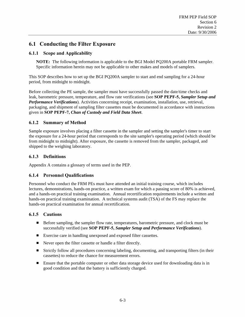
FRM PEP Field SOP Section 6
Revision 2 Date: 9/30/2006
6.1 Conducting the Filter Exposure 6.1.1 Scope and Applicability
NOTE: The following information is applicable to the BGI Model PQ200A portable FRM sampler. Specific information herein may not be applicable to other makes and models of samplers.
This SOP describes how to set up the BGI PQ200A sampler to start and end sampling for a 24-hour period, from midnight to midnight.
Before collecting the PE sample, the sampler must have successfully passed the date/time checks and leak, barometric pressure, temperature, and flow rate verifications (see SOP PEPF-5, Sampler Setup and Performance Verifications). Activities concerning receipt, examination, installation, use, retrieval, packaging, and shipment of sampling filter cassettes must be documented in accordance with instructions given in SOP PEPF-7, Chan of Custody and Field Data Sheet.
6.1.2 Summary of Method
Sample exposure involves placing a filter cassette in the sampler and setting the sampler's timer to start the exposure for a 24-hour period that corresponds to the site sampler's operating period (which should be from midnight to midnight). After exposure, the cassette is removed from the sampler, packaged, and shipped to the weighing laboratory.
6.1.3 Definitions
Appendix A contains a glossary of terms used in the PEP.
6.1.4 Personnel Qualifications
Personnel who conduct the FRM PEs must have attended an initial training course, which includes lectures, demonstrations, hands-on practice, a written exam for which a passing score of 80% is achieved, and a hands-on practical training examination. Annual recertification requirements include a written and hands-on practical training examination. A technical systems audit (TSA) of the FS may replace the hands-on practical examination for annual recertification.
6.1.5 Cautions
# Before sampling, the sampler flow rate, temperatures, barometric pressure, and clock must be successfully verified (see SOP PEPF-5, Sampler Setup and Performance Verifications).
# Exercise care in handling unexposed and exposed filter cassettes.
# Never open the filter cassette or handle a filter directly.
# Strictly follow all procedures concerning labeling, documenting, and transporting filters (in their cassettes) to reduce the chance for measurement errors.
# Ensure that the portable computer or other data storage device used for downloading data is in good condition and that the battery is sufficiently charged.
6-3

FRM PEP Field SOP Section 6
Revision 2 Date: 9/30/2006
6.1.6 Equipment and Supplies
# BGI PQ200A Air Sampler # COC Form # Field Data Sheet # Impactor well loaded with 37mm glass fiber filter and diffusion oil # Pre-weighed Teflon™ filter in cassette, with metal filter caps, in plastic resealable antistatic
cassette bag # 9” x 12” sealable plastic shipping bags # Marker (indelible ink).
6.1.7 Cassette Inspection
Handle the cassette as indicated in SOP PEPF-3, Filter Cassette Receipt, Storage, and Handling. Prior to working with cassettes, clean your hands with alcohol wipes or clean water. Allow hands to air dry.
1. Keep filter cassettes capped and in the antistatic filter cassette bags. The filter cassette bags should be stored in 9” x 12” self-sealing shipping bags until the cassettes are ready to be loaded into the portable sampler (see Figure 6-1)
Figure 6-1. Filter cassette equipment and filter cassette in antistatic sample bag.
6-4

FRM PEP Field SOP Section 6
Revision 2 Date: 9/30/2006
2. Remove one cassette, in its 3” x 5” antistatic, self-sealing cassette bag, from the 9” x 12”
shipping bag.
3. Remove the cassette from the antistatic, self-sealing cassette bag. Save this bag for post-sample transport!
4. Hold the cassette in a manner that will prevent contact with any part of the filter.
5. Carefully remove the filter caps and place them on top of the 3” x 5” antistatic, self-sealing plastic cassette bag with the interior side down.
6. Quickly visually inspect the filter and cassette for defects before use. Look for the following types of defects:
• Loose or improperly fitting cassette • Filter offset or wrinkled • Cassette number does not match COC information • Pinhole – A small hole • Loose material – Any extra loose material or dirt particles on the filter • Discoloration – Any obvious discoloration that might be evidence of contamination • Other – Any imperfections not described above that could affect the filter’s weight or
cause sampled air to bypass the filter medium.
7. Return any filter cassettes with visible damage or imperfections to the weighing laboratory along with the voided COC Form. Use a spare filter cassette in place of the defective filter cassette.
8. If the filter is acceptable, install the cassette per instructions in Section 6.1.8. Fill in the
“Transport of Filter and Field Site Information” on the COC Form that is associated with this cassette.
9. Indicate the filter type (e.g., RO-Routine, FB-Field Blank, CO-Collocated, TB-Trip Blank)
on the “Filter Type” area on the COC Form and write the filter type on the 3” x 5” plastic bag from which it came.
10. Place filter caps together (exterior side out) and return the caps in the same 3” x 5” antistatic,
self-sealing plastic cassette bag from which they came. Field blanks will be re-capped and stored inside the 3” x 5” bag. Seal the bag and store it in the portable sampler until sample collection is complete. Voided cassettes will be re-capped, stored inside the 3” x 5” bag, then placed inside the 9” x 12” bag along with its COC Form, and returned to the transport cooler for later shipment back to the weighing lab.
Best practice note: In case of high winds, the FS may need to tape or wedge the cassette bag inside the sampler case to avoid it being sucked out of the machine by the wind. It is possible for the filter bag to slip between the false bottom and the 4” square hole in the bottom of the case. Storing the 3” x 5” bag back inside the 9” x 12” bag should also prevent this from happening.
6-5
FRM PEP Field SOP Section 6
Revision 2 Date: 9/30/2006
6.1.8 Impactor and Cassette Installation
NOTE: The portable sampler is transported to the site, with a transport cassette and an empty transport WINS impactor assembly installed inside the main unit. See SOP PEPF-5, Sampler Setup and Performance Verifications, for the steps required to properly check the filter cassette and the WINS impactor, as well as for preparing a WINS impactor for sampling.
1. Prior to working with cassettes, clean your hands with alcohol wipes or clean water. Allow
hands to air dry.
2. Install a WINS impactor loaded with a 37-mm glass fiber filter and diffusion oil per SOP PEPF-5, Sampler Setup and Performance Verifications.
3. Select a filter cassette per Section 6.1.7, above.
4. Open the main unit door and carefully rotate the handle counterclockwise using both hands to expose the transport cassette and WINS assemblies. (CAUTION: Once the assembly has started to open, the weight of the two plates will tend to force the whole assembly open even further.)
5. The transport filter cassette and the WINS impactor should now be visible. If not, gently separate the filter cassette or WINS impactor from its respective upper housing.
6. Remove the transport cassette assembly, place it inside a storage container, and set it inside the main unit. Be sure this cassette is labeled properly to distinguish it from a sample cassette. If performing a field blank, proceed to Section 6.1.8.1; if not, go to Section 6.1.8.2.
6.1.8.1 Field Blank
Field blanks are used to measure possible contamination to filters during the loading and unloading procedure. Field blanks are designated by the field scientist on a schedule of one per week which should guarantee the requirement of 10% of all PEP routine filters stipulated by the QA Handbook.
1. If performing a field blank, install the field blank filter cassette. The Teflon™ filter medium needs to be facing up toward the WINS impactor.
2. Close the assembly by slowly rotating the handle clockwise 3/4 of a turn. Watch the filter cassette and WINS impactor to ensure that they are seated properly and that the assemblies close securely.
3. Open the assembly and remove the field blank.
4. Cap the blank filter cassette with the filter cassette caps that came with that cassette. Return the capped cassette to the same antistatic, self-sealing cassette bag from which it was removed. Seal the bag and place it into the main unit compartment. The blank will stay in the main unit for the same length of time as the routine filter. Make sure that the field blank is properly indicated on the COC Form.
6-6

FRM PEP Field SOP Section 6
Revision 2 Date: 9/30/2006
6.1.8.2 Trip Blank
Trip blanks are used to measure possible contamination to filters during transportation to and from sampling locations. They provide a frame of reference in case field blanks exhibit mass gain higher than the tolerance levels. Trip blanks should remain inside their protective bags and never be exposed to sampling procedures. Trip blanks account for approximately 5% of all PEP filters issued by the national weighing lab. They are designated by the weighing laboratory and issued at random. However, trip blanks should be used in conjunction with field blanks.
1. The trip blank should be treated in the same manner as all other PEP filters, with the exception of exposure. The filters should remain in their 3” x 5” anti-static, self-sealing plastic cassette bag at all times.
2. Transport the trip blank from the vehicle to the sampling location and return it to the transport cooler. Do not leave the trip blank inside the sampler during the sampling event.
3. Make sure that the trip blank is properly indicated on the COC Form. 6.1.8.3 Routine PE Filter
1. Install the sampling filter cassette in the filter cassette housing. The Teflon™ filter medium must face up toward the WINS impactor.
2. Close the assembly by slowly rotating the handle clockwise 3/4 of a turn. Watch the filter cassette and WINS impactor to ensure that they are seated properly and that the assemblies close securely.
6.1.9 Acquiring a 24-hour PE Sample
To comply with EPA regulation, the 24-hour sampling period begins at midnight (00:00) and concludes at midnight of the next day. The total sampling period is programmed for 24 hours (1440 minutes); however, if sampling during some other time period is required by the local site and has been approved by the COR, consult Section 6.1.10 of this SOP for instructions on resetting the sampling times in the BGI PQ200A air sampler. Section 6.1.11 describes the procedure to use if it is necessary to briefly stop and restart the sampler during a sampling period. Section 6.1.12 describes the controller screen outputs available for status monitoring during an exposure.
This procedure refers to use of the PQ200A control panel shown in Figure 6-2. Proceed as follows:
1. Install the PE filter cassette per Section 6.1.8, above. Ensure that all data have been recorded on the Field Data Sheet and the COC Form.
2. Verify that the reporting organization site operator has installed a filter in the routine sampler that is scheduled to be evaluated.
3. Enter the 4-digit cassette ID and the 9-digit AQS site ID into the PQ200A, as described in Section 6.1.9.1.
4. Program the FRM sampler’s software to perform the evaluation (Section 6.1.9.1).
6-7
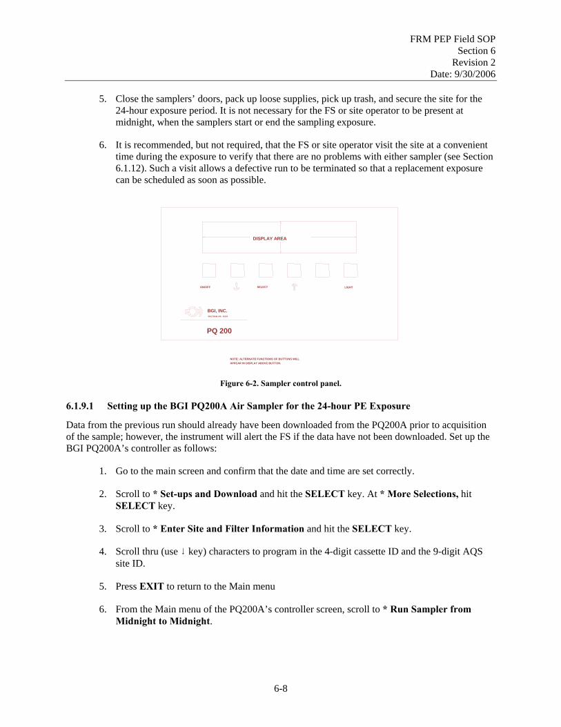
FRM PEP Field SOP Section 6
Revision 2 Date: 9/30/2006
5. Close the samplers’ doors, pack up loose supplies, pick up trash, and secure the site for the
24-hour exposure period. It is not necessary for the FS or site operator to be present at midnight, when the samplers start or end the sampling exposure.
6. It is recommended, but not required, that the FS or site operator visit the site at a convenient time during the exposure to verify that there are no problems with either sampler (see Section 6.1.12). Such a visit allows a defective run to be terminated so that a replacement exposure can be scheduled as soon as possible.
Figure 6-2. Sampler control panel.
6.1.9.1 Setting up the BGI PQ200A Air Sampler for the 24-hour PE Exposure
Data from the previous run should already have been downloaded from the PQ200A prior to acquisition of the sample; however, the instrument will alert the FS if the data have not been downloaded. Set up the BGI PQ200A’s controller as follows:
1. Go to the main screen and confirm that the date and time are set correctly.
2. Scroll to * Set-ups and Download and hit the SELECT key. At * More Selections, hit SELECT key.
3. Scroll to * Enter Site and Filter Information and hit the SELECT key.
4. Scroll thru (use 9 key) characters to program in the 4-digit cassette ID and the 9-digit AQS site ID.
5. Press EXIT to return to the Main menu
6. From the Main menu of the PQ200A’s controller screen, scroll to * Run Sampler from Midnight to Midnight.
BGI, INC.WALTHAM, MA. 02154
DISPLAY AREA
ON/OFF SELECT LIGHT
PQ 200
NOTE: ALTERNATE FUNCTIONS OF BUTTONS WILLAPPEAR IN DISPLAY ABOVE BUTTON.
6-8

FRM PEP Field SOP Section 6
Revision 2 Date: 9/30/2006
7. Press SELECT. If the unit has been previously downloaded, the following message will be
displayed:
Clearing Memory. Please Wait!
If the unit has not been downloaded, the following message will be displayed:
Current Data Not Yet Downloaded!
EXIT now or lose the current run data!
and then
Alarm Triggered Run, Saving Data!
In either case, the following message will be briefly displayed:
PQ200A Powering Down.
The PQ200A is then programmed to power itself on and begin sampling at midnight.
6.1.9.2 Data Displayed While the PQ200A is Running
During the exposure run, the PQ200A display will provide certain status information that may be useful in verifying that an exposure session is proceeding properly (see Section 6.1.12).
6.1.10 Running the Sampler with User-Defined Start/Stop Times
NOTE: FRM PEs are ordinarily conducted from midnight to midnight. This section is included for completeness or in case the FS, as directed by the COR, needs to adjust the start and end times to account for exceptional conditions, such as daylight savings time changes or the crossing of time zones.
# Be sure to note the exceptional exposure time on the Field Data Sheet.
# Data from a previous run should be downloaded prior to use of this function; however, the instrument will alert the operator if any previously acquired data has not been downloaded.
# From the Main menu, use the arrow keys until * Setups and Download flashes. Press SELECT.
# From the Set-Ups and Download menu, use the arrow keys until * Run w/ User Defined Start/Stop flashes. Press SELECT.
6-9

FRM PEP Field SOP Section 6
Revision 2 Date: 9/30/2006
# The Set the sample START DATE and TIME message will be displayed. The current selection
will be flashing on the second line.
# Press SELECT (NEXT). The first value (Day of the Month) will stop flashing, indicating that it can be edited.
# Use the arrow (EDIT) buttons to increase or decrease the selected value. When done press SELECT (NEXT).
# Continue to press the SELECT (NEXT) and arrow (EDIT) buttons in this fashion to enter the desired date and time.
# When done setting the start date and time, press the blank (EXIT) button to continue. If the unit has been previously downloaded, the following message will be displayed:
Clearing Memory. Please Wait!
# The Set the sample STOP DATE and TIME message will be displayed. The current selection will be flashing on the second line.
# Use the same procedure to set the stop date and time. When done, press the blank (EXIT) button to return to the Set-Ups and Download screen. Select * More Selections, then * Return to Main Screen.
6.1.11 Temporary Halt then Continue Sampling
During a PE sampling period, it is not desirable to halt sampling operations during a run of either the portable FRM PE sampler or the fixed site sampler. However, in an emergency, it may be necessary to suspend sampling for a brief period. Be sure to note any interruption of sampling on the Field Data Sheet, specifying the time and duration of the interruption, as well as the reason for the interruption. Interruptions in sampling activities for either the portable sampler or the fixed site sampler should be noted.
A 24-hour sample may be suspended for up to 1 hour and still remain a legitimate sample according to EPA rules; therefore, a means to temporarily halt and then resume sampling has been incorporated into the BGI PQ200A. To halt the sampler, simply press the ON/OFF button. The unit will jump to the Main menu and will display the following message:
Halted by Operator!
6-10
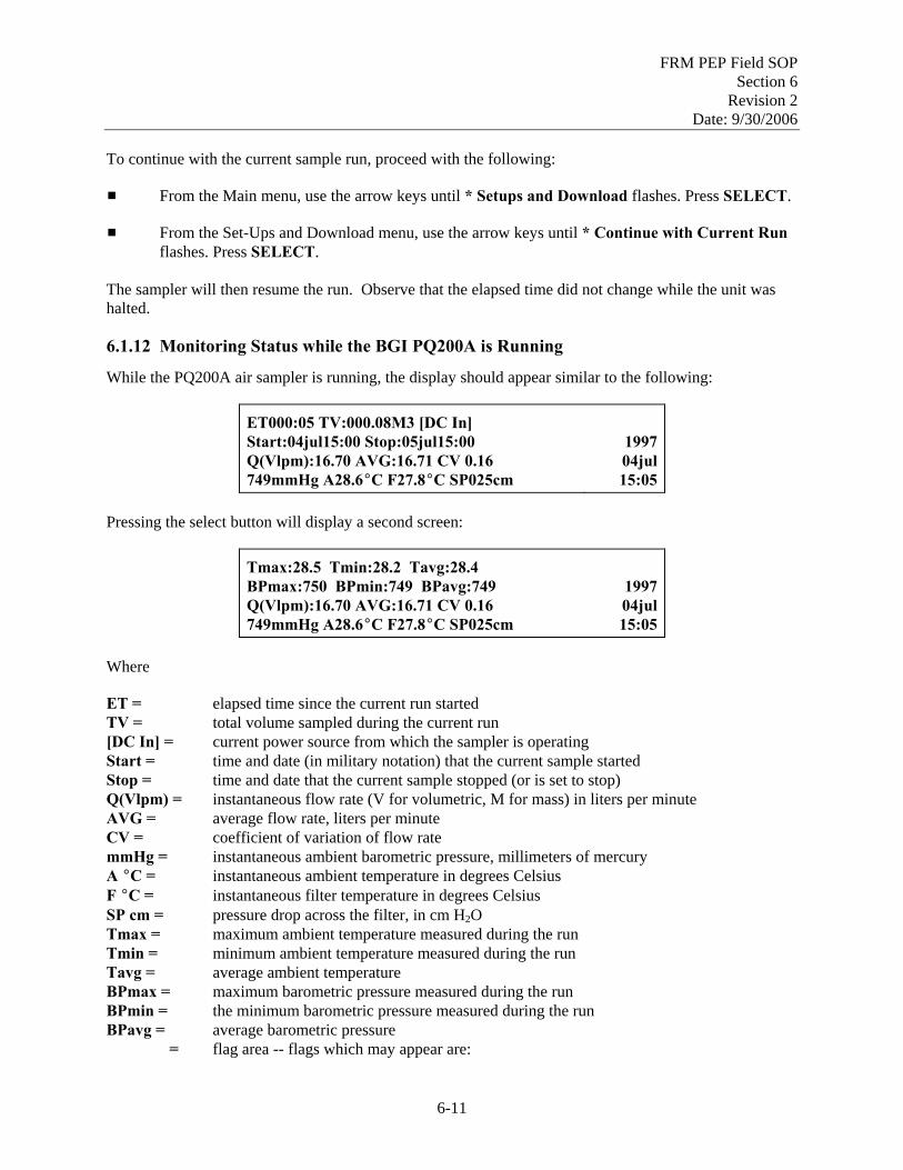
FRM PEP Field SOP Section 6
Revision 2 Date: 9/30/2006
To continue with the current sample run, proceed with the following:
# From the Main menu, use the arrow keys until * Setups and Download flashes. Press SELECT.
# From the Set-Ups and Download menu, use the arrow keys until * Continue with Current Run flashes. Press SELECT.
The sampler will then resume the run. Observe that the elapsed time did not change while the unit was halted.
6.1.12 Monitoring Status while the BGI PQ200A is Running
While the PQ200A air sampler is running, the display should appear similar to the following:
ET000:05 TV:000.08M3 [DC In] Start:04jul15:00 Stop:05jul15:00 Q(Vlpm):16.70 AVG:16.71 CV 0.16 749mmHg A28.6EC F27.8EC SP025cm
����� 1997 04jul 15:05
Pressing the select button will display a second screen:
Tmax:28.5 Tmin:28.2 Tavg:28.4 BPmax:750 BPmin:749 BPavg:749 Q(Vlpm):16.70 AVG:16.71 CV 0.16 749mmHg A28.6EC F27.8EC SP025cm
����� 1997 04jul 15:05
Where
ET = elapsed time since the current run started TV = total volume sampled during the current run [DC In] = current power source from which the sampler is operating Start = time and date (in military notation) that the current sample started Stop = time and date that the current sample stopped (or is set to stop) Q(Vlpm) = instantaneous flow rate (V for volumetric, M for mass) in liters per minute AVG = average flow rate, liters per minute CV = coefficient of variation of flow rate mmHg = instantaneous ambient barometric pressure, millimeters of mercury A EC = instantaneous ambient temperature in degrees Celsius F EC = instantaneous filter temperature in degrees Celsius SP cm = pressure drop across the filter, in cm H2O Tmax = maximum ambient temperature measured during the run Tmin = minimum ambient temperature measured during the run Tavg = average ambient temperature BPmax = maximum barometric pressure measured during the run BPmin = the minimum barometric pressure measured during the run BPavg = average barometric pressure �����= flag area -- flags which may appear are:
6-11

FRM PEP Field SOP Section 6
Revision 2 Date: 9/30/2006
P = a power failure has occurred Q = flow has varied more than +/- 5 percent F = a 5˚ filter overheat has occurred and lasted more than 30 minutes M = memory overflow (max run time with 5-minute logger interval) During operation, the SELECT (NEXT) button provides alternate displays of minimum, maximum, and average ambient temperatures and barometric pressures or other run time data. The ON/OFF button will temporarily suspend the run. The run is not considered complete until the Sample Stop Date and Time have been attained.
6.1.13 References
1. BGI Inc. 1998. PQ200 Air Sampler Instruction Manual. May.
2. BGI Inc. 1998. Audit Version - PQ200A, Appendix H in PQ200 Air Sampler Instruction Manual. August.
3. U.S. EPA (Environmental Protection Agency). 1998. Monitoring PM2.5 in Ambient Air Using
Designated Reference or Class I Equivalent Methods, Section 2.12 in Quality Assurance Handbook for Air Pollution Measurement Systems, Volume II, Part II. April draft.
6-12

FRM PEP Field SOP Section 6
Revision 2 Date: 9/30/2006
6.2 Sample Recovery and Data Download 6.2.1 Scope and Applicability
NOTE: The following information is applicable to the BGI Model PQ200A portable FRM sampler. Specific information herein may not be applicable to other makes and models of samplers.
This SOP describes how to collect the exposed filter cassette from a BGI PQ200A sampler.
Before collecting the PE sample, the sampler must have successfully passed the leak, temperature, barometric pressure, flow rate, and time verification checks. Activities concerning the receipt, examination, installation, use, retrieval, packaging, and shipment of the sampling filter cassette must be documented in accordance with instructions given in SOP PEPF-7, Chain of Custody and Field Data Sheet.
6.2.2 Summary of Method
After completion of 24-hour sample run, the FS returns to the site generally within 24 hours for “best practice,” documents sample run information, recovers the sample, and downloads the detailed sample run information to an electronic recording device. Collection within 48 hours is permissible due to holidays and weekends when a site is inaccessible.
6.2.3 Definitions
Appendix A contains a glossary of terms used in the PEP.
6.2.4 Personnel Qualifications
Personnel who conduct the FRM PEs must have attended an initial training course, which includes lectures, demonstrations, hands-on practice, a written exam for which a passing score of 80% is achieved, and a hands-on practical training examination. Annual recertification requirements include a written and hands-on practical training examination. A technical systems audit (TSA) of the FS may replace the hands-on practical examination for annual recertification.
6.2.5 Cautions
# Exercise care in handling unexposed and exposed filter cassettes # Never open the filter cassette or handle a filter directly # Strictly follow all procedures concerning labeling, documenting, and transporting filters (in their
cassettes) to reduce the chance for measurement errors # Ensure that the portable computer or other data storage device used for downloading data is in
good condition and that the battery is sufficiently charged. 6.2.6 Equipment and Supplies
# BGI PQ200A air sampler # COC Form # Field Data Sheet # Transport WINS impactor (clean) # Transport cassette
6-13

FRM PEP Field SOP Section 6
Revision 2 Date: 9/30/2006
# Protective filter cassette containers # 9” x 12” plastic shipping bags # Marker (indelible ink ) # Portable computer loaded with the PQ200A job controller software # 9-pin, female-female, RS-232 serial cable # Datatrans. # Portable data storage media (e.g., 3.5” data diskette, CD, or USB flash drive)
6.2.7 Procedure
6.2.7.1 Ending a Run
The FS will retrieve the filter cassette(s) after the exposure has terminated, typically the next day. PM2.5 filter cassette(s) should be removed within 24 hours for “best practice” after the sampling period ends. Collection within 48 hours is permissible due to holidays and weekends when a site is inaccessible. 48-to-96-hour collection is permissible in the case of emergency, but the weighing lab should be notified. The following steps describe shutdown procedures for the sampler:
1. A properly programmed PQ200A will automatically stop sampling at the end of 24 hours. Ensure that the sampler pump has stopped running. When the PQ200A has completed its run, the display screen will appear similar to the following:
SAMPLE RUN COMPLETED! 750mmHg A28.1EC F27.4 EC
1998 28OCT 15:55
2. From the above display, push the blank menu button to reach the Main menu screen. Select
* Review last run data and conditions. Scroll through the display screens and record summary information for the portable sampler during the 24-hour sampling period.
3. Review the recorded data for start and end times, sample elapsed time, flow rate, filter
quality, and temperature. This starts the process of determining if the sample is valid, questionable, or invalid. Record observations and reasons for questioning a run on the Field Data Sheet. Scan through the sampling summary on the sampler display and note flags, if present. The BGI PQ200A may display the following flags
P - Power failure M - Memory overflow F - 5EC filter overheating for > 30 min. Q - Flow variation of more than + 5% T – 24-hour sample time < 23 hours 50 minutes
4. If the exposure was not valid for any reason, the FS will contact the COR (or work directly with the state, depending on contractual agreements) to begin scheduling a second evaluation to replace the invalid evaluation. In either case, the COR should be notified of the change in schedule. This may require scheduling considerations that are beyond the scope of this SOP.
5. Clean hands with an alcohol wipe or clean water. Allow hands to air dry.
6-14

FRM PEP Field SOP Section 6
Revision 2 Date: 9/30/2006
6. Open the 3” x 5” antistatic cassette bag for the installed cassette, which was stored in the
main unit or other secure location. Remove the filter caps from the bag and set them on top of the bag, exterior side down.
7. Carefully rotate the handle of the filter chamber assembly counterclockwise using both hands
to expose the sample cassette and WINS impactor assemblies. (CAUTION: Once the assembly has started to open, the weight of the two plates will tend to force the whole assembly open even further.)
8. The sample filter cassette and the WINS impactor should now be visible. If not, gently
separate the filter cassette or WINS impactor from its respective upper housing.
9. Remove the sample filter cassette. Quickly inspect it for integrity and contamination (e.g., tears, bugs, etc.). Cap the filter cassette with its original filter caps. Place the capped cassette in the same 3” x 5” antistatic, self-sealing bag from which it was removed. Seal the bag.
10. Enter comments or flags on the Field Data Sheet. See Section 6.3 for packing and shipping
instructions.
11. Follow procedure in Section 6.2.7.2, below, to download run data.
12. See Section 6.4 for instructions on disassembly of the sampler. 6.2.7.2 Downloading Data from the PQ200A Air Sampler
Sampler data may be downloaded using a laptop computer or a Datatrans transfer device (Figure 6-3). The use of a laptop computer is recommended because the BGI software can capture fields that would otherwise need to be entered manually if one were using the Datatrans; however, the Datatrans can be used in situations, such as inclement weather or where safety concerns prevent the use of a laptop. The FS also has the option to transport the sampler to another location where it is more convenient to download data (e.g., vehicle or hotel room). As a last resort, the FS must record the information manually on the Field Data Sheet if there are problems with both the laptop computer and the Datatrans. To record data manually, follow the download instructions below, and at step 12, record the appropriate data. In most cases, summary data will be sufficient. However, if the 24-hour run did not complete, hourly data is advisable. Make a copy of these hand-written records and submit the originals to the lab along with the COC forms.
NOTE: This section describes the downloading process using a portable PC-compatible computer loaded with the PQ200 job controller software for MS Windows. Other methods of data downloading may be used and are described in the BGI PQ200 Manual.
Downloading to the Laptop PC
When the sampler has completed its run, the data may be downloaded from the memory of the PQ200A. Be sure to download the most recent run before setting the sampler to start another run.
1. Using a serial (9-pin) cable (female-female), connect the PQ200A sampler to a computer equipped with the PQ200 job controller program.
6-15

FRM PEP Field SOP Section 6
Revision 2 Date: 9/30/2006
2. Open the PQ200 program. Press the New File icon, and the New Job window will appear.
3. Enter a job name into the first line item. The file should be coded, with the first 4 characters being the month and day of the sample run (use leading zeros if necessary). For example, January 30th would be 0130. The next 4 characters will be the cassette ID number. This will make an 8- digit file name. The job file will automatically be given the suffix .job.
4. Tab to Job Code and enter any field flags as identified in Appendix B. Use commas to separate multiple flags (“,”).
5. Tab to Site Name and enter the site description (e.g., name of town, city location, etc.).
6. Tab to Station Code and enter the 9-digit AQS Site ID code that is also on the Site Data Sheet.
7. Tab to Operator and enter your initials. No other fields need to be entered.
8. Press Save. Select the appropriate subdirectory on the computer, then press OK to save the file.
9. Next, open the job file from the Main menu and select Download. The Download Summary and Logger Data window will appear. Under Options, choose Summary and Logger.
10. Click on Begin. After a short delay, the computer will begin receiving data from the PQ200A.
11. When the computer has finished receiving data from the PQ200A, click on Return. The serial cable may now be removed from the PQ200A sampler and the computer.
12. To view information about the data collected from the PQ200A, select the tabs: Summary, Hourly, or Logger.
13. To save the downloaded data to a portable storage media, select File Save from the Main menu. This will create and save the job file to the storage media.
14. The electronic data should be saved as two separate copies on a portable data storage media (e.g., data diskette or USB flash drive). One copy should be sent with the exposed filter cassette, COC Form, and Field Data Sheet to the national weighing laboratory. The other copy should be returned to the field office with the copies of the COC Forms and the Field Data Sheet.
Downloading Data using the Datatrans
The BGI Datatrans transfer device can be used to capture data from up to 20 sampling events using either the PQ100 or PQ200 Air Samplers. This transfer device can transport the “Run Data” from the field to the lab for analysis and storage. Its compact size, extended temperature ranges (-30°C to +60°C), and ease of operation make it ideal for field data retrieval when weather or safety issues prevent the use of a laptop computer.
6-16

FRM PEP Field SOP Section 6
Revision 2 Date: 9/30/2006
To start the Datatrans
1. Turn the unit on using the power switch on the front panel.
2. The following light sequence should be observed: red, yellow, and then green.
3. The green light will remain on. (This indicates that the unit is ready to use.) Downloading the PQ200 data to the Datatrans
1. Place the connection switch, located on the front panel, in the “Samp” (sampler) position.
2. Make sure that the PQ200 sampler is powered on.
3. Plug the Datatrans into the RS232 port on the front panel of the PQ200.
4. Press and release the pushbutton on the front of the Datatrans.
5. The red light will come on, and the green light will turn off. If communication is successful, the yellow light will flash for each line of data received.
6. When the download is complete, the yellow light will remain on, the red light will stop flashing and turn off, and the green light will light up.
7. If multiple samplers are set up, repeat the above steps to collect data from the sampling events on each sampler. Note that the data from any downloaded sampling events are stacked up using First In, Last Out methodology.
8. It is now safe to turn the unit off.
NOTE: The data will be retained in the Datatrans, even if the 9-volt battery fails, until it has been uploaded into a computer and the unit is erased using the data-deletion procedure described below.
To Upload data from the Datatrans to the Computer
1. Plug the Datatrans into the RS232 serial port of the computer.
2. Observe the following light sequence: red, yellow, and then green. (The green light indicates that the unit is ready. The yellow light indicates that data from sampling events are stored on the Datatrans.) The red light will turn off.
3. Place the connection switch, located on the front panel, in the (Comp) computer position.
4. Ensure that the computer is running PQ200 BGI Software and is ready to receive data as if it were attached directly to the sampler.
5. Point and click on BEGIN JOB. Follow the instructions given on the screen by the software. Enter any data applicable to the sampling event, such as initial filter weight, user data, etc.
6. Point and click on DOWNLOAD.
6-17

FRM PEP Field SOP Section 6
Revision 2 Date: 9/30/2006
7. Point and click on BEGIN.
8. The green light will turn off, the red light will turn on, and “Run Data” will be stored in the computer.
9. When END or MEM END is detected on the computer screen and the green light is lit on the Datatrans, the sampling data have been transferred.
10. If data from multiple sampling events have been stored in the Datatrans, the last run captured is the current resident run. While a run is resident, the Datatrans retains the characteristics of the sampler type from which it was captured. To access data from the next sampling event, download the data from the current run and then press the pushbutton on the Datatrans. Repeat this procedure until all of the data have been downloaded. You must “Begin” a new run for each sample run to be uploaded to the computer. When all runs have been uploaded, the yellow light will remain off.
NOTE (To recycle sample runs): After green light turns off, indicating that all runs have been downloaded, pressing the pushbutton will retrieve data from the series of runs. These data will remain until deleted. This is helpful if you are unsure of an uploaded run.
Data Deletion Procedure
To erase data from the Datatrans after the data from all sampling events have been transferred to a laptop computer:
1. Turn the power switch OFF.
2. Hold down the pushbutton.
3. While holding the pushbutton down, turn the power switch ON.
4. When the red light turns on, release the button.
5. When erased, all three lights will flash 2 times in unison and 1 time in series.
6. The unit is now cleared and ready for new downloads.
6-18

FRM PEP Field SOP Section 6
Revision 2 Date: 9/30/2006
Figure 6-3. DatatransTM
6-19

FRM PEP Field SOP Section 6
Revision 2 Date: 9/30/2006
6.3 Filter Packing and Shipment 6.3.1 Scope and Applicability
This procedure will describe packaging the sampled filter cassettes into shipping containers and transporting them to the national weighing laboratory.
6.3.2 Summary of Method
Ideally, PM2.5 filter cassettes should be removed from the sampler within 48 hours of the end of the collection period and shipped with 8 hours of sample removal. The sampled cassettes, Field Data Sheets, COC Forms, and portable data storage devices will be packed with ice substitutes and sent to the national laboratory by express courier using next-day air delivery. To ensure the timely receipt of the samples at the laboratory, shipments should be made only on Mondays through Thursdays, and weekend shipments should not be made. Note that the FS should ship the exposed filters within 8 hours of recovery on Mondays through Thursdays, and as soon as possible if samples are recovered on a Friday. If shipment cannot occur within these guidelines, the FS must have the chilled package shipped within 4 days of recovery.
6.3.3 Definitions
Appendix A contains a glossary of terms used in the PEP.
6.3.4 Personnel Qualifications
Personnel who conduct the FRM PEs must have attended an initial training course, which includes lectures, demonstrations, hands-on practice, a written exam for which a passing score of 80% is achieved, and a hands-on practical training examination. Annual recertification requirements include a written and hands-on practical training examination. A technical systems audit (TSA) of the FS may replace the hands-on practical examination for annual recertification.
6.3.5 Cautions # Exercise care in handling unexposed and exposed filter cassettes. # Never open the filter cassette or handle a filter directly. # Strictly follow all procedures concerning labeling, documentation, and transporting filters (in
their cassettes) to reduce the chance for measurement errors. 6.3.6 Equipment and Supplies # Capped cassettes containing pre-weighed/sampled Teflon™ filters (e.g., routine, field blanks,
collocated samples) and stored in 3” x 5” antistatic cassette bags # COC Form # Field Data Sheet # Filter shipping container # Ice substitutes stored in sealable plastic bags to protect from potential leakage (4 per shipping
container) # Digital max/min thermometer # Roll of bubble wrap # Heavy duty rubber bands
6-20

FRM PEP Field SOP Section 6
Revision 2 Date: 9/30/2006
# Masking tape # Packing tape # Knife or scissors # Two 9” x 12” plastic self-sealing shipping bags (1 for cassettes, 1 for the forms and portable data
storage media) # Portable data storage media (e.g., 3.5” data diskette, CD, or USB flash drive) 6.3.7 Procedure
This procedure describes the method of packing and shipping the sampled cassettes. When sampling is not occurring, the cassettes should always be capped and remain in their 3” x 5” antistatic, self-sealing cassette bags. This procedure creates a group of filter cassettes that are “sandwiched” between ice substitutes and wrapped in bubble wrap. This package is held together by either heavy-duty rubber bands or tape and is stored in a cooler.
1. Group all of the 3” x 5” antistatic bags containing the capped, sampled cassettes into one 9” x 12” plastic shipping bag and seal the bag. Ensure that there is a one-to-one match of COC Forms to sampled cassettes. For routine and collocated samples, there must also be a one-to-one match between the cassettes and the Field Data Sheets. Field blanks do not require a Field Data Sheet. Also ensure that the data storage media contains routine and collocated data.
2. Select the next preprinted express courier label. Record the air bill number in the “Shipping from Field to Weighing Lab” portion of each COC Form and complete the remainder of this portion of the form.
3. Find a working surface. Lay out a section of bubble wrap from the roll and place two ice substitutes on the wrap near the short edge.
4. Place the 9” x 12” plastic shipping bag containing the sampled cassettes on top of these ice substitutes. Unplug the digital max/min thermometer probe from the readout device and tape the probe onto the shipping bag over the sampled cassettes. Fold the empty portion of the bag over the probe 1 or 2 times.
5. Place two ice substitutes on top of the plastic shipping bag and probe.
6. Roll the bubble wrap around this ice substitute/cassette assembly (i.e., like wrapping a sandwich), and secure this assembly using masking tape or heavy rubber bands.
7. Connect the digital max/min thermometer probe to the readout device, and tape the readout device to the top of the ice substitute/cassette assembly.
8. Place the ice substitute/cassette assembly in the insulated shipping container. Allow the probe to equilibrate with the ice substitutes. This may take 5 minutes. If the ice substitutes are hard (frozen), the max/min thermometer’s current reading should be at least 0 OC
9. Separate the laboratory and field copies of the COC Forms and Field Data Sheets. Place the laboratory portions of the COC Forms, the Field Data Sheets, and the data storage device for all the samples in a second 9” x 12” plastic shipping bag. Retain the field copies.
6-21
FRM PEP Field SOP Section 6
Revision 2 Date: 9/30/2006
Note: If a data storage device is not available for mailing (e.g., the floppy drive on the laptop fails or the diskette is damaged) the FS may send data via email to the weighing lab. Specify the job code in the filename of the data file and in the subject line of the email. If multiple data files are to be submitted to the weighing lab, each should be sent in a separate email (so that the lab can easily sort by the email subject line to locate specific job codes).
10. Just before sealing the shipping container, reset the digital max/min thermometer by hitting the reset button until there is a click. This resetting will be confirmed by initial readings of “88.” Note: Flashing digits indicates that the battery is low and should be replaced.
11. Immediately place the 9” x 12” plastic shipping bag containing the COC Forms, Field Data Sheets, and the data storage media into the shipping container. Place additional bubble wrap in the container to minimize the movement of the ice substitute/cassette assembly during shipping. Close the container.
12. Seal the container with packing tape and apply a custody seal to indicate if the package has been tampered with.
13. Affix a preprinted express courier shipping label to the shipping container and transport the container to the nearest express courier shipping office. The FS should ship the exposed filters within 8 hours of recovery on Mondays through Thursdays, and as soon as possible (i.e., the following Monday) if the samples were recovered on a Friday. If a shipment can not occur within these guidelines, the FS must have the chilled package shipped within 4 days of recovery.
14. Call or e-mail the LA to report a sample shipment on the day of the shipment. The communication should include your name, the date, the airbill number, and the number of containers in the shipment.
If for some reason the sampled cassettes cannot be shipped on the day of filter recovery, complete Steps 1 through 12 above and use the following procedures for storing post-sampled filter cassettes at the field office.
a. Unpack the frozen ice substitutes from the post-sample shipping container and place them in the freezer.
b. Remove the 9” x 12” plastic shipping bag containing the COC Form, Field Data Sheets, and the data storage media from the post-sample shipping container and secure it in a safe place.
c. Remove the top from the shipping container and place the container in the refrigerator to cool the sampled filter cassettes to 4EC. The cassettes will remain capped in the 3” x 5” antistatic filter cassette bags. Leave the filter cassette bags in the 9” x 12” self-sealing shipping bags.
d. When the cassettes are ready to be shipped, complete steps 13 and 14 above.
6-22

FRM PEP Field SOP Section 6
Revision 2 Date: 9/30/2006
6.4 Sampler Disassembly 6.4.1 Scope and Applicability
This section describes the procedure for sampler disassembly, which occurs after sample exposure and data collection have been completed. This section contains materials specific for the BGI PQ200A air sampler and may not be applicable to other sampler makes and models.
6.4.2 Summary of Method
The method for disassembly is essentially the reverse of assembly. As with assembly, it is important to follow proper procedures to avoid damage to and minimize wear and tear on the sampler.
6.4.3 Definitions
Appendix A contains a glossary of terms used in the PEP.
6.4.4 Personnel Qualifications
Personnel who conduct the FRM PEs must have attended an initial training course, which includes lectures, demonstrations, hands-on practice, a written exam for which a passing score of 80% is achieved, and a hands-on practical training examination. Annual recertification requirements include a written and hands-on practical training examination. A technical systems audit (TSA) of the FS may replace the hands-on practical examination for annual recertification.
6.4.5 Cautions
1. When the sampler is dismantled, be sure to remove any debris adhering to the base or legs before storing the legs for transport. To minimize contamination, always pack the base or leg portion of the sampler apart from the sampler collection module. If inadvertently transferred to the sample collection filter enclosure, a small particle of dust or pollen will alter the sample weight dramatically.
2. Care must be taken during handling not to crack or break the water collector jar attached to the side of the inlet. To minimize the chance of accidental breakage, the glass water collector jar may be replaced with a plastic jar or wrapped with insulating tape to lessen the shock of rough handling.
6.4.6 Procedure
If the FRM sampler is being disassembled for transport to a new site, follow these steps after the sample has been removed:
1. Power the unit down and disconnect the electricity.
2. Remove the WINS impactor.
3. Clean the impactor well, as described in Section 5.8.7.1, and return the impactor to Travel Case No. 2.
6-23
FRM PEP Field SOP Section 6
Revision 2 Date: 9/30/2006
4. Place the transport cassette into the filter compartment and install an empty transport
impactor well (no oil or filter). The BGI PQ200A air sampler should always be shipped or stored with a transport filter cassette in place.
5. Close the filter chamber assembly by slowly rotating the handle clockwise 3/4 of a turn until the cam follower clicks into the indent on the cam. Watch the filter cassette and WINS impactor to ensure that they are seated properly and that the filter chamber assembly closes securely.
6. Disassemble the sampler in the reverse order of set-up (Section. 5.1).
7. Check the sampling site to ensure no equipment and supplies are left at the site.
6.4.7 References
1. BGI Inc. May 1998. PQ200 Air Sampler Instruction Manual. 2. BGI Inc. 1998. PQ200A Audit Sampler, Appendix H in PQ200 Air Sampler Instruction Manual.
August. 3. U.S. EPA (Environmental Protection Agency). 1998. Monitoring PM2.5 in Ambient Air Using
Designated Reference or Class I Equivalent Methods, Section 2.12 in Quality Assurance Handbook for Air Pollution Measurement Systems, Volume II, Part II. April draft.
6-24

FRM PEP Field SOP Section 6
Revision 2 Date: 9/30/2006
6.5 Sampler Maintenance and Cleaning 6.5.1 Scope and Applicability
This SOP describes the routine procedures for maintaining and cleaning the sampler.
NOTE: This SOP contains material that is specific for the BGI PQ200A air sampler and may not be applicable to other makes and models of sampler.
6.5.2 Summary of Method
The PM2.5 PEP samplers will be regularly checked and cleaned to ensure reliable operation and avoid contamination, which could affect the quality of resultant data. Some activities should ideally be performed in the field in concert with disassembly (e.g., cleaning the WINS impactor well and the legs of the sampling device).
6.5.3 Definitions
Appendix A contains a glossary of terms used in the PEP.
6.5.4 Personnel Qualifications
Personnel who conduct the FRM PEs must have attended an initial training course, which includes lectures, demonstrations, hands-on practice, a written exam for which a passing score of 80% is achieved, and a hands-on practical training examination. Annual recertification requirements include a written and hands-on practical training examination. A technical systems audit (TSA) of the FS may replace the hands-on practical examination for annual recertification.
6.5.5 Cautions
# The FS must properly install and maintain the sampler to prevent damage and contamination. Be particularly attentive to maintenance of the pump, ensuring the soundness of electrical and pneumatic connections that will be repeatedly assembled and disassembled.
# Check the numerous O-rings periodically. Clean and lubricate their surfaces as required for ease of assembly and the maintenance of leak-free seals. Replace O-rings that are split, brittle, or cracked. Use only O-rings specified for this equipment.
6.5.6 Equipment and Supplies
# Low-lint wipes # Isopropyl alcohol # Wooden dowel (downtube cleaning) # Lint-free pipe cleaner # Marking pencil # Soft brush (interior cleaning) # Plastic bristle baby bottle cleaning brush # Distilled water (general use found at pharmacies/grocery store) # Field Data Sheet
6-25

FRM PEP Field SOP Section 6
Revision 2 Date: 9/30/2006
# Selections of O-rings # Silicone vacuum grease # Safety pins or dental pick.
Table 6-1. Summary of PM2.5 Sampler Maintenance Activities
Frequency Maintenance item
Every visit 1. 2. 3
Inspect and, if necessary, empty water collector bottle. Clean or change-out WINS impactor well. Inspect O-rings of filter chamber assembly.
Every 10 sampling events or as needed.
1. 2.
3. 4. 5. 6. 7.
Clean sampler inlet surfaces. Clean main (first-stage) size-selective inlet (PM10 head) and inspect the O-ring. Clean WINS impactor housing and impactor jet surfaces. Examine O-rings. Clean interior of sampler case. Check condition of sample transport containers. Clean sampler downtube. Inspect and service cooling air intake filter and fans.
Quarterly (every 3 months) 1.
2. 3.
4. 5.
Inspect O-rings of main (first-stage) size-selective inlet. Apply light coat of vacuum grease, if required. Clean sampler downtube. Inspect and service O-rings and water-seal gasket where the downtube enters sampler case. Inspect and service O-rings of filter chamber assembly. Inspect and service vacuum tubing, tube fittings, and other connections to pump and electrical components.
6.5.7 Procedure
Several of the sampler components will need to be maintained and cleaned periodically. Table 5-1 indicates the maintenance schedule of the important sampler components. The FS may also utilize the checklists at the end of this section entitled “Maintenance and Repair Following Every 10th Run Event” and “Quarterly Maintenance and Repair.”
6.5.7.1 WINS Impactor Well Cleaning
To clean the WINS impactor well, perform the following tasks:
1. Separate the upper and lower portions of the well.
2. Remove the used filter from the well. Try to avoid getting diffusion oil on the outside surfaces of the impactor well.
3. Using lint-free wipes, wipe clean the two halves of the well and any other surface that may have been exposed to oil.
4. Reassemble the well and place it in the impactor cup.
6-26

FRM PEP Field SOP Section 6
Revision 2 Date: 9/30/2006
5. Clean hands to remove any oil residue.
6. Do not replace the filter and oil unless preparing to sample.
6.5.7.2 Main (first-stage) Size-Selective Sampler Inlet, Downtube, and Sampler Interior
This part of the procedure is usually accomplished in the field office.
To dismantle and clean the sampler inlet and other components, follow these steps:
1. Mark each assembly point of the sampler inlet with a pen or pencil to provide “match marks” during reassembly.
2. Disassemble the sampler’s size-selective inlet unit according to the manufacturer’s instructions, taking care to retain all the parts. An exploded view of the inlet is shown in PEPF-5, Section 5.1, Sampler Assembly, Figure 5-5. NOTE: If the assembly screws appear frozen, the application of penetrating oil or commercial lubricant will make removal easier. Be sure to completely wipe off any excess oil before proceeding.
3. Using a soft brush and lint-free wipes, lightly scrub all interior surfaces of the inlet and bug screen with distilled water. CAUTION: Some edges may be sharp! Pay particular attention to small openings and crevices. Lint-free wipes and/or a small, soft brush are most helpful in these areas. Using wipes moistened with distilled water, remove any remaining deposits. Completely dry all components.
4. Reassemble the unit in reverse order by aligning the parts according to the previously scribed match marks. Take particular care to ensure that all O-ring seals are properly seated, sealed, and lubricated, and that all screws are uniformly tightened.
5. Clean the downtube interior by forcing or pulling a plug of water-moistened, lint-free wipes through the tube with a dowel. Do not scrape or abrade the interior surfaces. Allow to dry. Inspect the O-rings.
6. With the filter chamber assembly open, inspect the interior of the impactor housing, both above and below the impactor well. These areas should be clean, dry, and free from oil. If necessary, clean the areas with a lint-free wipe. Clean the interior of the impactor jet using a lint-free pipe cleaner or similar tool. The upper impactor housing may be removed to do this. Do not score or abrade the jet orifice surfaces.
7. Without removing them, check all the O-rings for distortion, cracks, fraying, lack of a light coating of vacuum grease, or other problems. Use a flashlight to get a good look at their condition. Replace or recondition as necessary.
8. Close the filter chamber assembly to keep out dust.
9. Wipe down or dust the interior of the sampler’s main unit to remove bugs, dirt, and/or water deposits that may have collected inside the unit. Inspect the cooling air intake filter and clean or replace it if necessary.
6-27

FRM PEP Field SOP Section 6
Revision 2 Date: 9/30/2006
6.5.7.3 Service and Replacement of O-rings and Tubing
There are 10 O-rings in the flow path of the BGI PQ200A sampler. O-rings are also part of the flow rate adapter and the Chinook StreamlineTM FTS. Plastic tubes connect sampler components to the pump. A small plastic tube connects the atmospheric pressure sensor to the exterior of the sampler’s main case. Flexible rubber or plastic tubing is also part of the flow rate and pressure sensors used in verification and calibration.
It is expected that some of the O-rings and tubing will need to be serviced and replaced because use and exposure to the elements cause these parts to degrade. To detect problems and make repairs, follow these guidelines:
# Frequently inspect O-rings that hold the sampler inlet and the downtube in place. These O-rings are subject to wear each time the portable sampler is assembled and disassembled.
# To allow the inlet and downtube and the downtube and upper impactor housing to fit together easily, put a light coat of silicone vacuum grease on their O-rings and wipe off any excess with a laboratory tissue. Resist the temptation to apply too much grease. It is the O-ring that makes the seal, not the grease! Excessive grease may dissolve in the O-ring and cause it to wear out sooner.
# Inspect the O-rings in the assemblies that hold the WINS impactor and the filter cassette. These O-rings must be free of dust or debris that could score or indent the assemblies and create leakage channels. A flashlight and magnifying lens may be needed to detect brittleness, cracks, or indentations. These O-rings are not subject to sliding friction and generally do not need to be coated with silicone grease.
# Suspect O-rings as the cause of leak check failures, but first determine that sealing pressure is adequate and look for loose tubing or connecting fittings.
# Remove O-rings carefully. Do not use tools that could score or nick the metal surfaces and channels where the O-rings are seated. Use of a plastic or wooden stick to dislodge a faulty O-ring is preferable to a knife blade! A small metal pin or a dental pick may be used to dig into the O-ring and pull it away from the channel so that the ring can be grasped and removed.
# Remove all grease and dust from the metal channel before inserting a new O-ring. Be sure the new O-ring is properly aligned and fully seated before use.
# Inspect all types of tubing for cracks and brittleness. Replace as needed. Cracks often occur at the point where the tube is connected to a port or fitting.
# Periodically inspect all compression fittings, electrical connections, and mounting screws or bolts, etc., for signs of loosening due to use and vibration. Tighten or replace as needed. Unusual noises or excessive vibration may indicate something is loose.
6-28

FRM PEP Field SOP Section 6
Revision 2 Date: 9/30/2006
Section 6.5: Sampler Maintenance and Cleaning
Field Data Forms
6-29

FRM PEP Field SOP Section 6
Revision 2 Date: 9/30/2006
[This page intentionally left blank.]
6-30

FRM PEP Field SOP Section 6
Revision 2 Date: 9/30/2006
Maintenance and Repair Following Every 10th Run Event
Check Monitor # _______________ Date:_________ FS:____________________
Clean sampler inlet surfaces: Disassemble main (first-stage) size-selective inlet; use a soft brush, wipes, and water/alcohol to clean the surfaces. Check O-ring, wipe dry, and reassemble.
Clean the downtube: Use wooden dowel to push moistened wipes through the tube, covering the entire interior surface. Allow to dry. Check O-rings
Clean WINS impactor housing and impactor jet surfaces: Inspect opened impactor housing. Wipe down surfaces with wipes. Use pipe cleaner to clean out impactor jet. Check O-rings.
Clean interior of sampler case: Wipe down interior surfaces with moistened wipes. Check all remaining O-rings.
Clean cooling fan and filter: Check that fan operates and that no debris is caught in fan box. Check that filter is in place and that it is not damaged or due for replacement.
Clean and inspect transport cases: Remove any trash and wipe out if necessary. Check that transport cases for signs of excessive wear and re-glue loose boards or cushioning. Check transport case inventory.
Comments/Notes:
6-31
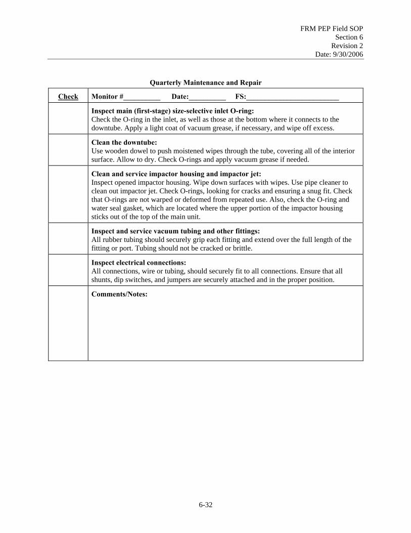
FRM PEP Field SOP Section 6
Revision 2 Date: 9/30/2006
Quarterly Maintenance and Repair
Check Monitor #__________ Date:__________ FS:_________________________
Inspect main (first-stage) size-selective inlet O-ring: Check the O-ring in the inlet, as well as those at the bottom where it connects to the downtube. Apply a light coat of vacuum grease, if necessary, and wipe off excess.
Clean the downtube: Use wooden dowel to push moistened wipes through the tube, covering all of the interior surface. Allow to dry. Check O-rings and apply vacuum grease if needed.
Clean and service impactor housing and impactor jet: Inspect opened impactor housing. Wipe down surfaces with wipes. Use pipe cleaner to clean out impactor jet. Check O-rings, looking for cracks and ensuring a snug fit. Check that O-rings are not warped or deformed from repeated use. Also, check the O-ring and water seal gasket, which are located where the upper portion of the impactor housing sticks out of the top of the main unit.
Inspect and service vacuum tubing and other fittings: All rubber tubing should securely grip each fitting and extend over the full length of the fitting or port. Tubing should not be cracked or brittle.
Inspect electrical connections: All connections, wire or tubing, should securely fit to all connections. Ensure that all shunts, dip switches, and jumpers are securely attached and in the proper position.
Comments/Notes:
6-32
FRM PEP Field SOP Section 7
Revision 2 Date: 9/30/2006
Field Standard Operating Procedures for the PM2.5 FRM Performance Evaluation Program
Section 7
Chain of Custody and Field Data Sheet SOP: PEPF-7
Name: Printed Signature Date
Dennis Crumpler
Contents Section Page
7.1 Chain of Custody and Field Data Sheet ...........................................................................................7-3 7.1.1 Scope and Applicability ......................................................................................................7-3 7.1.2 Summary of Method ...........................................................................................................7-3 7.1.3 Definitions...........................................................................................................................7-3 7.1.4 Personnel Qualifications .....................................................................................................7-3 7.1.5 Cautions ..............................................................................................................................7-3 7.1.6 Equipment and Supplies......................................................................................................7-3 7.1.7 Procedure ............................................................................................................................7-3
Forms Page
COC PM2.5 Federal Reference Method Performance Evaluation Program Chain-of-Custody Form ....................................................................................................................................7-11 FDS PM2.5 Federal Reference Method Performance Evaluation Program Field Data Sheet
for BGI PQ200A ..................................................................................................................7-12
7-1

FRM PEP Field SOP Section 7
Revision 2 Date: 9/30/2006
[This page intentionally left blank.]
7-2
FRM PEP Field SOP Section 7
Revision 2 Date: 9/30/2006
7.1 Chain of Custody and Field Data Sheet 7.1.1 Scope and Applicability
This SOP applies to the Chain of Custody (COC) and Field Data Sheet (FDS) procedures used in the field for the FRM PEP.
7.1.2 Summary of Method
The COC procedure for the PM2.5 PEP is used to track the path of individual filter cassettes from the national weighing laboratory to the field and back again. After the filter has been weighed, the COC begins when the filter is placed in a cassette. A COC Form accompanies each filter cassette. The form stays with the filter as it is sent to the field, exposed (or used as a blank), and returned to the original weighing laboratory. The FDS is used by the FS to record information about sampler verifications and exposure data.
7.1.3 Definitions
Appendix A contains a glossary of the terms used in the PEP.
7.1.4 Personnel Qualifications
Personnel who conduct the FRM PEs must have attended an initial training course, which includes lectures, demonstrations, hands-on practice, a written exam for which a passing score of 80% is achieved, and a hands-on practical training examination. Annual recertification requirements include a written and hands-on practical training examination. A technical systems audit (TSA) of the FS may replace the hands-on practical examination for annual recertification.
7.1.5 Cautions
1. Ballpoint pens rather than markers should be used when filling out information on the COC Form or Field Data Sheet because these documents are 3-part carbonless forms.
2. Mistakes are to be documented by marking a single horizontal line through the error, writing
correct information in the available space, and initialing and dating the correction.
7.1.6 Equipment and Supplies
FRM PEP COC Form
Field Data Sheet
7.1.7 Procedure
7.1.7.1 COC Form
The COC Form is printed on 3-part carbonless paper. The form itself is divided into five parts, which are filled out at different locations, as described below. Parts II – IV, discussed below, indicate where additional instructions on filling out the COC Form can be found.
7-3

FRM PEP Field SOP Section 7
Revision 2 Date: 9/30/2006
PART I - Weighing laboratory (Laboratory SOPs) Part I of the COC Form is filled out at the laboratory. This portion of the form contains the filter ID number, cassette number, some supporting information, and shipping information from the laboratory to the field office. The “Date This Filter Must be Used by” field in this part of the form is very important and indicates the last day that the filter may be used. This date is calculated as 30 days after the weighing date. The filter exposure must begin no more than 30 days after weighing. Another important item in this part of the form is the return address. All filters must be returned to the laboratory from which they originated.
NOTE: One copy (the pink “Laboratory Analyst”) of the multi-part form is retained by the laboratory after Part I has been completely filled out. The remaining two copies are sent to the field office.
Use of pre-printed labels with all of the above information may be used rather than transcribing labels. When pre-printed labels are used, one label should be attached in Part I to each of the three copies of the COC Form.
PART II - Field office (SOP PEPF-3)
Part II is filled out by the field office and by the FS when the cassettes are received (see SOP PEPF-3, Filter Cassette Receipt, Storage and Handling, for instructions). This part contains identifying information about the field organization, the recipient, and the integrity of the received shipment.
PART III - Field site (SOP PEPF-6)
Part III is filled out at the site, usually before filter exposure. The “Sampling Event Information” consists of:
Arrival Date at Site – Date that the filter cassette is transported to the monitoring site. This need not be the date that the sample was taken.
Sampler Operator – This is the name of the PEP field scientist.
Site Name and Description – List the name of the sampling location and any relevant description for identification purposes.
Primary Site Sampler – This refers to the fixed PM2.5 sampler operated at the site for compliance purposes. Indicate the make/model of the sampler, as well as the serial number.
AQS Site ID – List the 9-digit identification code for the air monitoring site.
Other Operators or Observers – List the name and affiliations of any assisting operators or other official observers, such as representatives of EPA or the local air monitoring authority.
Event Filter Integrity –Visual inspection of the filter prior to installation is described in SOP PEPF-7, Sampler Filter Handling. If the filter passes visual inspection, the FS should place a checkmark in the “OK” box. If any defects were noted, the FS should place a checkmark in the “Reject” box and describe the imperfection in the space provided. If additional space is required, use the “Notes” section at the bottom of the form.
7-4

FRM PEP Field SOP Section 7
Revision 2 Date: 9/30/2006
Under “Sampling Event Filter Data”, the FS should list the Sampling Date. Next, complete the “Sample Type” section, which identifies how the filter is used at the site. The six options are the following:
RO - Routine FRM PE sample.
CO - Collocated FRM PE sample that is collected by the FS at the same time and at the same site as the regular FRM PE sample. Whenever the FS takes two simultaneous samples, the primary (routine) and collocated PE samplers should be designated before the exposure begins.
FB - Field blank filter cassette that is used by the FS as a blank (see SOP PEPF-6, Sample Filter Handling). Also, specify the cassette ID for the associated Routine sample.
TB - Trip Blank filter cassette that is transported to and from the field by the FS. The 3” x 5” antistatic bag remains unopened throughout the trip.
Expired Filter (not used) – Filter cassette has exceeded the “Date This Filter Must be Used by” (from Part I of the COC). This filter cassette should not be used for a PEP sampling event. It should be returned to the weighing lab.
Other – A filter cassette that is in some other category (for example, a special type of QA or QC sample). The FS should always provide additional information about type of sample in the “Notes” section.
If the FS considers the filter to be invalid for any reason, the “Void” box should be checked. Describe the reason for voiding a filter in the space provided, or in the “Notes” section if additional space is required. Some possible reasons for voiding a filter include visible contamination on the filter, sampler malfunction, or a discrepancy in the COC documentation.
PART IV-Field filter shipping to weighing lab (SOP PEPF-6)
Part IV should be filled out completely. The FS should normally package and ship the exposed filter cassettes and any accompanying field or trip blank filter cassettes within 8 hours of sample recovery. This section is used to record shipping information.
Shipment Date – List the scheduled shipment date for the package.
Affiliation – This refers to the affiliation of the FS.
Shipped by – This refers to the FS unless shipping is delegated to another person.
From and To – Indicate shipping locations. “To” refers to the destination and should always be the same weighing laboratory that provided the filter cassette (as indicated in Part I of the COC Form).
Airbill No. – Fill in the airbill number for the scheduled shipment.
Shipped via – Indicate the shipment method. For the PEP, this is usually “Federal Express”.
NOTE: After Part IV has been completed, the FS should retain the “Field Scientist” (yellow) copy of the COC Form for the field office records. The remaining “Original” (white) portion of the form is returned to the laboratory with the filter cassette(s), the completed Field Data Sheet(s), data diskettes or other portable storage media, and any additional written notes.
7-5
FRM PEP Field SOP Section 7
Revision 2 Date: 9/30/2006
PART V – National weighing laboratory
The final part of the COC Form primarily documents the condition of the container upon receipt at the national weighing laboratory, but also includes the “Notes” section. The “Notes” section is available for the FS and LA to record any relevant notes. If additional space is necessary, extra pages should be attached. The FS should retain a copy of any additional pages attached to the form. Once the form returns to the weighing laboratory, the data are entered from the form, and the form is archived.
7.1.7.2 Field Data Sheet
The Field Data Sheet is printed on 2-part carbonless paper. The FS originates a new Field Data Sheet in the field as verification checks begin. After all the sampler verifications have been successfully completed and documented, an unexposed filter cassette is selected, and its cassette number is entered on the Field Data Sheet. A summary of exposure data is also included on the sheet. These data are sufficient to calculate the PM2.5 concentration in the event that the electronic data downloaded from the sampler are lost.
NOTE: A Field Data Sheet is only required for filter cassettes that have actually been sampled in an FRM sampler. Thus, only filters cassettes that are designated as “RO-Routine”, “CO-Collocated”, or, in some cases, “Other” on the COC Form will have completed Field Data Sheets. Field blanks and trip blanks associated with these samples are also documented on the Field Data Sheet.
Complete the “Sampling Event Information”, listing the “AQS Site ID,” “Sampling Date,” “Site Name,” “PEP Field Scientist,” and serial numbers for both the FRM sampler and the BGI PQ200A sampler. Enter the identification numbers for all transfer standards used to verify the FRM sampler in the “Parameter Check Device” section. For multi-standard instruments (such as the BGI TriCal and DeltaCal), use the first line to indicate the make/model and serial number for the device.
“Time Checks OK?” is used to indicate the results of synchronization of the FRM sampler’s clock with an external standard (must agree within 1 minute). Describe any discrepancies with the synchronization in the space provided. “Monitoring Site Criteria OK?” is used to record whether the siting criteria were met by the FRM sampler. Describe any violations of these criteria in the space provided.
The “PQ200A PEP Sampler Verification Checks” section must be filled out using the associated verification SOPs (see SOP PEPF-5, Sampler Setup and Performance Verifications). The acceptance criteria are listed on the Field Data Sheet for reference. Some older verification devices may require a relatively complex equation for calculating the flow rate based on the pressure drop across an orifice (see Appendix E). The documentation accompanying each orifice device provides the necessary equations and the constants applicable to the orifice. Be sure to record the Date the verification checks were performed. It may be different from the Sampling Date.
The “Exposure Data” section contains the identification number of the filter cassette used for this exposure. This number should be entered as soon as the filter cassette is loaded into the FRM sampler and the filter chamber is closed. Also, list the cassette IDs of those filter cassettes (field blank, trip blank, and collocated) that are directly associated with a single 24-hour exposure.
The remainder of this section is filled out after the FRM PE has concluded. “Filter Integrity OK?” is used to indicate whether or not the exposed filter appeared to be free of visible imperfections (e.g., pinholes or
7-6

FRM PEP Field SOP Section 7
Revision 2 Date: 9/30/2006
debris) when it was removed from the sampler. “Data Download OK?” is used to indicate the success or failure of the electronic data download from the sampler.
If the BGI PQ200A displays any of the following flags, record them in the “Sampler Flags” section:
P - Power failure M - Memory overflow F - 5EC filter overheating for > 30 min. Q - Flow variation of more than + 5% T – 24-hour sample time < 23 hours 50 minutes Refer to Appendix B for a list and description of other field qualifiers which should be recorded in the “Field Flags” section as relevant. The remaining exposure information is taken directly from the sampler’s screen.
The “Notes” section is available for the FS to record all relevant notes here. Use extra pages if necessary. The FS should retain a copy of any additional pages attached to the Field Data Sheet.
NOTE: The FS will retain the “Field Scientist” (yellow) copy of the Field Data Sheet for the field office records. The FS will return the “original” (white) copy of the Field Data Sheet to the weighing laboratory with the COC Form and the filter cassette. In the laboratory, the data on the Field Data Sheet are entered into the database, and the Sheet is archived.
7-7

FRM PEP Field SOP Section 7
Revision 2 Date: 9/30/2006
[This page intentionally left blank.]
7-8

FRM PEP Field SOP Section 7
Revision 2 Date: 9/30/2006
Section 7.1: Chain of Custody and Field Data Sheet
Field Data Forms
7-9

FRM PEP Field SOP Section 7
Revision 2 Date: 9/30/2006
[This page intentionally left blank.]
7-10

FRM PEP Field SOP Section 7
Revision 2 Date: 9/30/2006
FORM COC
7-11

FRM PEP Field SOP Section 7
Revision 2 Date: 9/30/2006
FORM FDS
7-12
FRM PEP Field SOP Section 8
Revision 2 Date: 9/30/2006
Field Standard Operating Procedures
for the PM2.5 FRM Performance Evaluation Program
Section 8 Quality Assurance/Quality Control
SOP: PEPF-8
Name: Printed Signature Date
Dennis Crumpler
Contents Section Page
8.1 Quality Assurance/Quality Control...............................................................................................8-3 8.1.1 Scope and Applicability...................................................................................................8-3 8.1.2 Summary of Method ........................................................................................................8-3 8.1.3 Definitions .......................................................................................................................8-5 8.1.4 Personnel Qualifications ..................................................................................................8-5 8.1.5 Cautions ...........................................................................................................................8-5 8.1.6 Equipment and Supplies ..................................................................................................8-5 8.1.7 Completeness ...................................................................................................................8-5 8.1.8 Field Blanks .....................................................................................................................8-5 8.1.9 Trip Blanks ......................................................................................................................8-5 8.1.10 Accuracy ..........................................................................................................................8-5 8.1.11 Collocated Sampling........................................................................................................8-6 8.1.12 Collocation Coding ..........................................................................................................8-7 8.1.13 Standards Recertifications ...............................................................................................8-8
8.2 Field Data Verification/Validation................................................................................................8-9 8.2.1 Scope and Applicability...................................................................................................8-9 8.2.2 Summary of Method ........................................................................................................8-9 8.2.3 Definitions .......................................................................................................................8-9
8-1
FRM PEP Field SOP Section 8
Revision 2 Date: 9/30/2006
8.2.4 Personnel Qualifications ..................................................................................................8-9 8.2.5 Procedure .........................................................................................................................8-9
Tables Page 8-1. Field Quality Control Checks ............................................................................................................8-3 8-2. Developing the AQS Site ID for a Once-a-Year or Once-a-Quarter Collocation .............................8-8 8-3. Parameters to be checked on PED Data Report and Field Data Summary Report ..........................8-11 Figures Page 8-1. Collocation scenario. .........................................................................................................................8-7 8-2. Field data verification/validation flow...............................................................................................8-9 Forms Page Field Data Verification/Validation/Correction Form (FDV) ...................................................................8-15
8-2

FRM PEP Field SOP Section 8
Revision 2 Date: 9/30/2006
8.1 Quality Assurance/Quality Control 8.1.1 Scope and Applicability
This SOP describes the QA and QC procedures that will be implemented at prescribed frequencies during routine PEP activities.
8.1.2 Summary of Method
This SOP summarizes the important QA/QC procedures that must be accomplished as part of the PM2.5 FRM PEP and provides procedures for those activities that have not been reviewed in other sections. QA/QC procedures documented in the other PEP Field SOPs are not discussed in this section. Table 8-1 summarizes the PEP field QC checks.
Table 8-1. Field Quality Control Checks
Requirement Frequency Acceptance Criteria SOP
Reference
Filter Holding Time
Pre-sampling All filters < 30 days before sampling PEPF-2
Filter collection All filters ≤ 48 hoursa PEPF-2
Filter shipmenta All filters 8 hours after retrievalb PEPF-2
Data Completeness
Data completeness Quarterly 75% PEPF-8
Filter
Visual defect check All filters See reference PEPF-6
Field QC Checks
Field filter blank 1 per week for each FS ±30 µg change between weighings
PEPF-8
Calibration/Verification of Sampler (Using normal PE verification devices)
Clock/timer verification Every sampling event 1 min/mo PEPF-5
External leak check Every sampling event <80 mL/min PEPF-5
Internal leak check Upon failure of external leak check
<80 mL/min PEPF-5
Single-point barometric pressure verification
Every sampling event ±10 mmHg PEPF-5
Multi-point barometric pressure verification
1 per year or upon failure of the single-point verification
±10 mmHg PEPF-10
Barometric pressure calibration
Upon failure of the multi-point verification
±10 mmHg PEPF-10
Single-point temperature verification
Every sampling event ±2 °C of standard PEPF-5
8-3

FRM PEP Field SOP Section 8
Revision 2 Date: 9/30/2006
Requirement Frequency Acceptance Criteria SOP
Reference
Multi-point temperature verification
1 per year or upon failure of the single-point verification
± 2 °C of standard PEPF-10
Temperature calibration Upon failure of the multi-point verification
Adjust to within ± 0.1 °C of standard
PEPF-10
Single-point flow rate verification
Every sampling event ±4% of indicated flow or ±5% of design flow (16.67)
PEPF-5
Multi-point flow rate verification
1 per year or upon failure of the single-point verification
±2% of transfer standard PEPF-10
Flow Rate (FR) calibration
Upon failure of the multi-point verification
±4% of design flow (16.67) PEPF-10
Accuracy (Using independent verification devices)
External leak check 4/yr < 80 mL/min PEPF-8
Internal leak check As needed < 80 mL/min PEPF-8
Barometric pressure audit 4/yr ±10 mmHg PEPF-8
Temperature audit 4/yr ±2 °C of standard PEPF-8
Flow rate audit 4/yr (manual) ±4% of audit standard PEPF-8
Precision (Using collocated samplesc)
All samplers (mandatory) 1/year CV < 10% PEPF-8
Paired (Option 1) 1/month CV < 10% PEPF-8
All samplers (Option 2) 1/quarter CV < 10% PEPF-8
Standards Recertifications
Field barometer 1/yr ±1 mmHg resolution ±5 mmHg accuracy
PEPF-8
Field thermometer 1/yr ± 0.1o C resolution ± 0.5o C accuracy
PEPF-8
Flow rate transfer standard 1/yr ±2% of NIST-traceable standard PEPF-8
Working mass standards 3-6 mo 0.025 mg PEPF-8
Primary mass standards 1/yr 0.025 mg PEPF-8 a PEP filters should be routinely recovered within 24 hours after conclusion of exposure. 48-hour collection is permissible due
to holidays and weekends when the site is inaccessible. These filters get a 48-hour collection flag. 48-to-96-hour collection is permissible in the case of an emergency (e.g., sickness, accident, etc.). If the collection time is greater than 96 hours, the sample will receive an invalidation flag.
b The FS should ship the exposed filters within 8 hours of recovery on Mondays through Thursdays and as soon as possible if the sample is recovered on a Friday. If shipment can not occur within these guidelines, the FS must store the filters at ≤ 4°C and then have the chilled package shipped within 4 days of recovery.
c Once per year, all of the PEP samplers used by a single FS or Region must be collocated and run at the same location over the same time period. These are often referred to as “annual parking lot collocations.” In addition, the FS must collocate all of their PEP samplers on one of two schedules: monthly — 2 or more PEP samplers are collocated with another routine PEP sampler (“paired collocations”), OR quarterly— all of samplers are collocated and run at the same location over the same time period (“quarterly parking lot collocations”).
8-4

FRM PEP Field SOP Section 8
Revision 2 Date: 9/30/2006
8.1.3 Definitions
Appendix A contains a glossary of the terms used in the PEP.
8.1.4 Personnel Qualifications
Personnel who conduct the FRM PEs must have attended an initial training course, which includes lectures, demonstrations, hands-on practice, a written exam for which a passing score of 80% is achieved, and a hands-on practical training examination. Annual recertification requirements include a written and hands-on practical training examination. A technical systems audit (TSA) of the FS may replace the hands-on practical examination for annual recertification.
8.1.5 Cautions
The activities described in the procedure below refer to the SOPs where the activity is described. The referenced SOPs provide the appropriate cautions.
8.1.6 Equipment and Supplies
The activities described in the procedure below refer to the SOPs where the activity is described. The referenced SOPs provide the appropriate equipment and supply lists.
8.1.7 Completeness
Completeness is a measure of the amount of valid data obtained from a measurement system compared to the amount that was expected to be obtained. Each Region has information about the expected number of sites that need a PE, and the PEP is expected to obtain valid data for at least 75% of these sites each quarter.
8.1.8 Field Blanks
Field blanks are used to capture any contamination that occurs in the transportation stage and the field implementation stage of the PEP. One field blank is temporarily installed by an FS each week. The FS should randomly choose the sampler in which to use the field blank each week (described further in SOP PEPF-6, Filter Exposure and Concluding the Sampling Event).
8.1.9 Trip Blanks
Trip blanks are used to capture any contamination that may occur in the transportation stage of the PEP. Trip blanks are transported to a sampling location but are not subjected to sampling conditions. Trip blanks are designated by the weighing lab and should be used in association with field blanks (described further in SOP PEPF-6, Filter Exposure and Concluding the Sampling Event).
8.1.10 Accuracy
Once every 3 months, the FS will perform the following tasks on all actively used samplers: 1. External leak check 2. Internal leak check 3. Temperature audit
4. Pressure audit 5. Flow rate audit.
8-5

FRM PEP Field SOP Section 8
Revision 2 Date: 9/30/2006
These audits will be performed using the same procedures as those used for the verification checks (described in SOP PEPF-5, Sampler Setup and Performance Verifications). The difference is that these audits will be performed with an independent verification device that is not the verification device used for everyday verifications. They must be accomplished with either the standard used for multipoint verification/calibration or a spare verification device that is not used in normal operations.
8.1.11 Collocated Sampling
Collocated sampling provides an estimate of the precision or repeatability of the portable sampler and the measurement system. Each FS or Region must collect collocated samples using each sampler in the PEP. For collocation to provide the most accurate analysis of precision, the PEP QAPP states it is necessary that each filter exhibit a mass gain of at least 6 µg (average ambient 24-hr concentrations of 0.25µg/m3 will produce the needed mass gain). If the locality selected for a collocation study traditionally does not experience concentrations that produce a mass gain 6 µg, then the collocation study should be set-up to run for 48 hours.
Once-a-Quarter Collocation (Option 1, Preferred)
Every three months (quarterly), all portable samplers being used by any one FS or Region must be set up and run at the same location over the same time period. This is referred to as a “quarterly parking lot collocation,” because the collocation events often take place in the parking lot of the Regional field office. Each 24-hour sampling run is considered an “event”. Recall under conditions of low ambient concentrations an event may need to run for 48 hours to obtain 6 µg of total mass gained. The start time can be adjusted (e.g., noon to noon) to accomplish multiple sampling events in a shorter time frame. The samplers will be placed within 1-4 meters of each other and their inlets will be within 1m of the vertical height. It is suggested that these samplers run for 3 sampling events (minimum two events) to provide enough data to ensure that the results are repeatable over several days. The filters will be sent to the national weighing laboratory for processing using normal procedures described in the PEP Field SOPs. Under this option, the final collocation study must be the annual collocation of all samplers for the Region. It is conducted at the end of the calendar year in which the PEP audits and previous collocation events have been performed.
Once-a-Month Collocation (Option 2)
If Quarterly collocations with all of a Region’s PEP samplers is not an option, The FS may choose to collocated one or more of his or her samplers either together in a parking lot study or at an FRM site, which is preferred. This is often referred to as a “paired collocation,” although two or more PEP samplers may be collocated at a time. The goal is to include all PEP samplers in the collocation rotation, but if space is limited (which may occur at FRM sites) give priority to the most frequently used samplers. In the case of collocation at an FRM site or a parking lot the FS should select sites that traditionally experience ambient concentrations that are greater than 0.25µg/m3 or 6 µg of total mass gained. The PEP Sampler(s) must be located 1-4 meters of all other portable PEP samplers in the study and samples will be collected as described in the PEP Field SOPs. The filters will be sent to the national weighing laboratory for processing using normal procedures described in the PEP Field SOPs. Under this option, the final collocation study must be the annual collocation of all samplers for the Region. It is conducted at the end of the calendar year in which the PEP audits and previous collocation events have been performed.
8-6

FRM PEP Field SOP Section 8
Revision 2 Date: 9/30/2006
Once-A-Year Collocation
Once per year, all PEP portable samplers being used in the Region must be set up and run at the same location over the same time period. This is referred to as the “annual parking lot collocation” because the collocation events often take place in the parking lot of the Regional field office. Each 24-hour sampling run is considered an “event”. Recall under conditions of low ambient concentrations an event may need to run for 48 hours to obtain 6 µg of total mass gained. The start time can be adjusted (e.g., noon to noon) to accomplish multiple sampling events in a shorter time frame. The samplers will be placed within 1-4 m of each other, and their inlets will be within 1m of the vertical height. It is suggested that these samplers run for 3-4 sampling events to provide enough data to ensure that the results are repeatable over several days. (Note: Each of these sampling events should be run with a new filter.) The filters will be sent to the national weighing laboratory for processing using normal procedures described in the PEP Field SOPs. This annual event will replace either 1 monthly collocation or one quarterly event described above.
8.1.12 Collocation Coding
The following summary describes how to code collocated samples. Assigning the proper code to collocated samples is important to ensure that the data are correctly imported into the Performance Evaluation Database (PED). Figure 8-1 provides an example of how to code collocated samples.
Scenario 1: PEP Primary and Collocated instrument at an Actual Region 5 Site
State Primary PEP CollocatedPEP RoutineMonitor SamplerSampler
AQS ID- 390950024AQS ID- 390950024AQS ID- 390950024
Figure 8-1. Collocation scenario.
Scenario 2: PEP Collocated instruments at the Region 5 Parking Lot (monthly/annually)
PEP CollocatedSampler
AQS ID- 39region5
PEP CollocatedSampler
AQS ID- 39region5
PEP CollocatedSampler
AQS ID- 39region5
1-4 metersof primary
1-4 metersof routine
PM 2.5
Monitor
Blah Blah M onitorsd
Durham, NC Incorporate
Note: It is appropriate to locate the collocated PE sampler within 1-4 meters of the State Primary also. However, if space is limited it is not required.
Note: All monitors should be located within 1-4 meters. Refer to look-up table for the two digit State Code.
8-7

FRM PEP Field SOP Section 8
Revision 2 Date: 9/30/2006
1. When conducting a Once-a-Month collocation at a SLAMS/NAMS site where a state/local primary
sampler is running, load the 9-digit AQS Site ID into the BGI sampler’s second User ID field (Figure 8-1, Scenario 1). When conducting a Once-a-Year or Once-a-Quarter collocation in the Regional parking lot, use the convention displayed below in Table 8-2 to determine the AQS Site ID. Note that these types of collocations do not have actual AQS Site IDs, and a 9-character code is used.
Table 8-2. Developing the AQS Site ID for a Once-a-Year or Once-a-Quarter Collocation
Region State where Regional
Office Located State Code Use the following surrogate AQS code (must be 9 characters long)
1 MA 25 25region1
2 NJ 34 34region2
3 MD 24 24region3
4 GA 13 13region4
5 IL 17 17region5
6 TX 48 48region6
7 MO 29 29region7
8 CO 08 08region8
9 CA 06 06region9
10 WA 53 53region0 2. When conducting a Once-a-Month Collocation at a SLAMS/NAMS site where a State/local primary
sampler is running, identify the PEP sampler that best meets the siting criteria as the “Routine FRM” sampler. Identify other PEP sampler as the “Collocated FRM” sampler (Figure 8-1, Scenario 1).
When conducting a Once-a-Year or Once-a-Quarter Collocation in the Regional parking lot, use “Collocated” as the filter type on the COC Form for all of samples collected (Figure 8-1, Scenario 2).
3. When conducting a Once-a-Month Collocation at a SLAMS/NAMS site where a state/local primary sampler is running, enter the state/local primary sampler make/model and serial number on the COC Form for the routine PEP sampler. Enter the make/model and serial number of the routine PEP sampler on the COC Form associated with the collocated PEP sampler.
When conducting a Once-a-Year or Once-a-Quarter Collocation in the Regional parking lot, enter “NA” in the make/model and serial number area of all of the COC Forms.
8.1.13 Standards Recertifications
All primary and transfer standards will be recertified as NIST-traceable and will have 1-year warranties. During EPA purchase of this equipment, agreements were set up to provide this recertification service. EPA will inform the FS of where and when to send standards for this recertification.
8-8

FRM PEP Field SOP Section 8
Revision 2 Date: 9/30/2006
8.2 Field Data Verification/Validation 8.2.1 Scope and Applicability
This SOP describes the QA procedures that will be implemented to verify and validate field data. Verification refers to the process of examining the result of a given activity to determine result’s conformance with stated requirements. Validation refers to examining a result to determine its conformance to user needs.
8.2.2 Summary of Method
Figure 8-2 summarizes the field data verification/validation procedure. Once a month (between the second and third week of the month), the national weighing laboratory will send an electronic report of the data from the PED to each Region’s COR and FS(s). This report will include the information entered electronically from the Field Data Sheets. The laboratory will also send the FS a Field Data Verification/Validation/Correction Form (Form FDV). The FS will review the field information, affirm its validity by initialing the hard-copy or electronic Form FDV, indicate any necessary edits on Form FDV, and initial beside any edits. The laboratory personnel making the edit will initial after the edit has been completed. The FS will summarize the data that is
validated in monthly reports to the COR. Figure 8-2. Field data verification/validation flow.
8.2.3 Definitions
Appendix A contains a glossary of the terms that will be used in the PEP.
8.2.4 Personnel Qualifications
Personnel who conduct the FRM PEs must have passed the written and hands-on practical training examinations for the field component in the PM2.5 FRM PEP. A technical systems audit (TSA) of the FS may replace the hands-on practical examination.
8.2.5 Procedure
The national weighing laboratory will generate a Form FDV for each Regional Office. This form may be in hard-copy or electronic (spreadsheet) format and will include the Filter ID, Cassette ID, Filter Type, and Sample Date for samples from that Region. Once started, new data will be added monthly to provide a complete record for the year.
8-9

FRM PEP Field SOP Section 8
Revision 2 Date: 9/30/2006
Between the second and third Monday (~10th calendar day) of each month, the national weighing laboratory will post data on its website for review by the Regional COR(s) and FS(s). This will include an electronic PED data report, the Field Data Sheet information for all available data from the previous data shipment (prior month), and the FDV Form. The laboratory will keep a record of each monthly data shipment to the Regions based on Filter ID. The FS will need his or her copies of the COC Forms (Form COC) and Field Data Sheets, as well as an electronic or hard-copy version of the portable sampler data. The FS will not be asked to check data that is automatically transferred from the sampler; only values (e.g., cassette ID, AQS Site ID [including POC, if known], flags, run date) that are entered manually will require inspection.
Table 8-3 identifies the parameters that should be reviewed for both sets of data sent to the field offices. The “key” fields for both data sets are the cassette IDs and the filter IDs; however, other parameters on the Form COC and the Field Data Sheet should also be reviewed because they may not have been completed or entered correctly. The FS will be responsible for communicating these edits to the LA on Form FDV.
1. The FS will receive the PED data report, the Field Data Sheet information, and Form FDV from the national weighing laboratory.
2. The FS will review all of the field-generated data with the exception of the data transferred electronically from the sampling instrument. The FS will verify that these data are complete and validate that the data values are correct.
3. If the data for both the PED and the Field Data Sheets are correct, the FS will mark the respective “PED DB OK” and “Field Data Sheet OK” fields with a “Y”, initial the “FS Initial” field, and enter the date reviewed into the “FS Date” field (see Form FDV with example data). If any of the data need to be corrected, follow Steps 4–12, below.
4. If the data are not correct, place an “N” in the “PED DB OK” field to indicate that the data in the PED needs to be corrected or place an “N” in the “Field Data Sheet OK” field to indicate that the field data sheet data should be corrected (see Form FDV with example data). Note that each correction should be entered on a separate line of the form, even if multiple parameters related to the same filter ID require editing.
5. Using Form FDV, identify the parameter that needs to be corrected and enter the parameter name in the “Parameter” field. The parameter names used in the PED Data Report and Field Data Summary Report are in listed in the first column of Table 8-3 and will be the same as those used on Form FDV. The corresponding parameter names used in Form COC and the Field Data Sheet are listed in the second column.
6. Enter the current (incorrect) value into the “Current Value” field on Form FDV.
7. Place the correct value in the “Correct Value” field.
8. Initial the “FS Initial” field, and enter the date the data were reviewed in the “FS Date” field.
9. Add comments to explain why the value was changed.
8-10
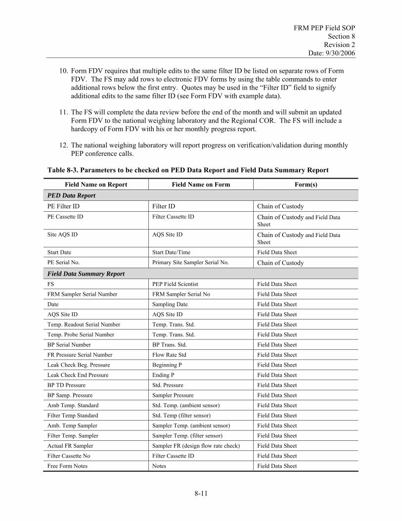
FRM PEP Field SOP Section 8
Revision 2 Date: 9/30/2006
10. Form FDV requires that multiple edits to the same filter ID be listed on separate rows of Form
FDV. The FS may add rows to electronic FDV forms by using the table commands to enter additional rows below the first entry. Quotes may be used in the “Filter ID” field to signify additional edits to the same filter ID (see Form FDV with example data).
11. The FS will complete the data review before the end of the month and will submit an updated Form FDV to the national weighing laboratory and the Regional COR. The FS will include a hardcopy of Form FDV with his or her monthly progress report.
12. The national weighing laboratory will report progress on verification/validation during monthly PEP conference calls.
Table 8-3. Parameters to be checked on PED Data Report and Field Data Summary Report
Field Name on Report Field Name on Form Form(s)
PED Data Report PE Filter ID Filter ID Chain of Custody PE Cassette ID Filter Cassette ID Chain of Custody and Field Data
Sheet Site AQS ID AQS Site ID Chain of Custody and Field Data
Sheet
Start Date Start Date/Time Field Data Sheet
PE Serial No. Primary Site Sampler Serial No. Chain of Custody
Field Data Summary Report FS PEP Field Scientist Field Data Sheet
FRM Sampler Serial Number FRM Sampler Serial No Field Data Sheet
Date Sampling Date Field Data Sheet
AQS Site ID AQS Site ID Field Data Sheet
Temp. Readout Serial Number Temp. Trans. Std. Field Data Sheet
Temp. Probe Serial Number Temp. Trans. Std. Field Data Sheet
BP Serial Number BP Trans. Std. Field Data Sheet
FR Pressure Serial Number Flow Rate Std Field Data Sheet
Leak Check Beg. Pressure Beginning P Field Data Sheet
Leak Check End Pressure Ending P Field Data Sheet
BP TD Pressure Std. Pressure Field Data Sheet
BP Samp. Pressure Sampler Pressure Field Data Sheet
Amb Temp. Standard Std. Temp. (ambient sensor) Field Data Sheet
Filter Temp Standard Std. Temp (filter sensor) Field Data Sheet
Amb. Temp Sampler Sampler Temp. (ambient sensor) Field Data Sheet
Filter Temp. Sampler Sampler Temp. (filter sensor) Field Data Sheet
Actual FR Sampler Sampler FR (design flow rate check) Field Data Sheet
Filter Cassette No Filter Cassette ID Field Data Sheet
Free Form Notes Notes Field Data Sheet
8-11

FRM PEP Field SOP Section 8
Revision 2 Date: 9/30/2006
[This page intentionally left blank.]
8-12
FRM PEP Field SOP Section 8
Revision 2 Date: 9/30/2006
Section 8.2: Field Data Verification/Validation
Field Data Forms
8-13

FRM PEP Field SOP Section 8
Revision 2 Date: 9/30/2006
[This page intentionally left blank.]
8-14

FRM PEP Field SOP Section 8
Revision 2 Date: 9/30/2006
FORM FDV Field Data Verification/Validation/Correction Form
Filter ID Cass. ID
Filter Type
Sample Date
PED DB OK
(Y/N)
Field Data Sheet OK
(Y/N)
Parameter Current Value
Correct Value
FS Initial
FS Date Lab Correction
Initials
L Date Comment
T1234567 2415 RO 12/29/98 Y N Amb. Samp. Temp
25.8 28.5 AAA 10/15/98
“ “ “ “ Amb. Temp
Standard
25.8 28.5 AAA 10/15/98
T1235678 2319 RO 1/5/98 Y Y AAA 10/15/98
Form FDV with example data
8-15

FRM PEP Field SOP Section 8
Revision 2 Date: 9/30/2006
[This page intentionally left blank.]
8-16

FRM PEP Field SOP Section 9
Revision 2 Date: 9/30/2006
Field Standard Operating Procedures
for the PM2.5 FRM Performance Evaluation Program
Section 9
Information Retention SOP: PEPF-9
Name: Printed Signature Date
Dennis Crumpler
Contents Section Page
9.1 Information Retention ......................................................................................................................9-3 9.1.1 Scope and Applicability...................................................................................................9-3 9.1.2 Information Included in the Reporting Package ..............................................................9-5 9.1.3 Data Retention/Archive ...................................................................................................9-8 9.1.4 References........................................................................................................................9-8
Tables 9-1. PM2.5 Reporting Package Information. ............................................................................................9-3 9-2. Field Measurements. ........................................................................................................................9-7
9-1

FRM PEP Field SOP Section 9
Revision 2 Date: 9/30/2006
[This page intentionally left blank.]
9-2

FRM PEP Field SOP Section 9
Revision 2 Date: 9/30/2006
9.1 Information Retention 9.1.1 Scope and Applicability
The Federal Records Act (44 U.S.C. 31) and other statutes require all federal agencies to create records that document their activities, file records for safe storage and efficient retrieval, and dispose of records according to Agency schedules. This SOP defines which records are critical to the project, what information needs to be included in reports, and which data reporting format and document control procedures should be used.
The following information describes the document and records procedures for the PEP field activities. In EPA’s QAPP regulation and guidance, EPA uses the term “reporting package.” This term is defined as herein as all the information required to support the concentration data reported to EPA, which includes all of the required data, as well as any data deemed important by the PEP. Table 9-1 identifies these documents and records by the Agency File Code (AFC) function and schedule numbers. It would be acceptable to have an overarching file called “PEP” for the purposes of locally delineating these files from other programs.
Table 9-1. PM2.5 Reporting Package Information
Agency File Code
Function No.
Category Record/Document Types
006 Program Management Files
006.1
Management and Organization
• Organizational structure for EPA and how the regions and ESAT contractors fit into running the PEP
• Organizational structure for the support contractors
• PEP project plans, and subsequent revisions • Quality management plan
006.2
Monitoring Site Information
• Site characterization file (site data sheets) • Site maps • Site pictures • SLT site contact information
006.3
Field Operations and Data Acquisition – by EPA Regional Staff or Contractors in Behalf of EPA
• QA project plans • Standard operating procedures (SOPs) • Field logbooks and communications • Sample handling/chain of custody forms
EPA 301-093
006.4
Communications (Contractor Technical Project Activity)
• Telephone record and email between contractor and state/local/tribal agencies
• Telephone record and email between contractor and COR
9-3

FRM PEP Field SOP Section 9
Revision 2 Date: 9/30/2006
Agency File Code
Function No.
Category Record/Document Types
006.5
Communications (EPA Project Activity)
• Telephone record and email between EPA regional or headquarters staff and state/local/tribal agencies and vice versa
• Telephone record and email between EPA regional and other EPA personnel (headquarters to regions and vice versa)
EPA 301-093
006.6
Equipment and Instruments Used by Contractors in the PEP [records about charged time to the support of the program would go to EPA 405-202]
• Inventories of capital equipment, operating supplies and consumables
• Repair and maintenance • Retirement or scrapping
202 Contract Management Records EPA 405
202.1 Contract Administration • Work assignments, task orders, delivery orders, and work plans
• Contractor monthly reports • Technical directives from contract officer
Representative (COR) to contractor • Invoices for consumables • Requisite qualifications of field scientists and lab
technicians for PEP-related, contractor-implemented activities
• Training records and certificates of contractors conducted and issued by EPA regional ESAT COR
179 Special Purpose Programs EPA 404-142-01
179.1 Data Administration and Integration
• Data management plans/flowcharts • Raw data: any original data (routine and QC data)
including data entry forms • Data algorithms • Documentation of PEP database (PED)
(national/regional level) • PM2.5 PED data • Field data sheets and chain-of-custody forms
173 Data Files Consisting of Summarized Information EPA 404-142-01
173.1 Data summaries, special reports, progress reports
• Data/summary/monthly field activity reports • Journal articles/papers/presentations • Data validation summaries
9-4

FRM PEP Field SOP Section 9
Revision 2 Date: 9/30/2006
Agency File Code
Function No.
Category Record/Document Types
237 State and Local Agency Air Monitoring File EPA 108-025-01-01
237.1 Quality Control/Quality Assurance
• 3-year PEP QA reports • PEP data quality assessments • QA reports • Response/corrective action reports • Site audits
036 Routine Procurement EPA 405
036.1 Acquisition of capital equipment and supplies by EPA, either headquarters or regional office
• Needs assessments and reports • Program copies of purchase requests • Requests for bids or proposals • Proposals, bids or quotations • Bills of lading • Warranties and certificates of performance • Evaluations of proposals, bids, quotations or trial
installations
122 Supervisors’ Personnel Files and Duplicate Official Personnel Folder (OPF) Documentation
EPA 403-256
122.1 Personnel qualifications, training and certifications
• COR training certifications • Certification as PEP field scientist trainer and/or
lab technician trainer
9.1.2 Information Included in the Reporting Package
9.1.2.1 Data Reporting Package Format and Document Control
The PEP has structured its records management system according to EPA’s File Plan Guide (see http://www.epa.gov/records/tools/toolkits/filecode/). A file plan lists the records in your office, and describes how they are organized and maintained. A good file plan is one of the essential components of a recordkeeping system, and key to a successful records management program. It can help you:
• document your activities effectively • identify records consistently • retrieve records quickly • disposition records no longer needed • meet statutory and regulatory requirements
The PEP records management system uses the Agency File Codes to facilitate easy retrieval of information during EPA technical systems audits (TSAs) and reviews. The PEP records management system also follows EPA records schedules, which constitute EPA's official policy on how long to keep Agency records (retention) and what to do with them afterwards (disposition). For additional information on EPA records schedules, see http://www.epa.gov/records/policy/schedule/ (the website is searchable by AFC function code and schedule number).
9-5

FRM PEP Field SOP Section 9
Revision 2 Date: 9/30/2006
Table 9-1 lists the documents and records that will be filed according to the statute of limitations discussed in Section 9.1.4. To archive the information as a cohesive unit, all the PEP PM2.5 information will be filed under the major code “PEP,” followed by the AFC function and schedule numbers listed in Table 9-1. For example, PEP project plans would be filed under the heading “PEP/EPA 301-093-006.1” and chain-of-custody forms would be filed under “PEP/EPA 301-093-006.3.”
9.1.2.2 Field Notebooks
The PEP will issue field notebooks to each FS. Each field notebook will be uniquely numbered and associated with the individual FS and the PM2.5 PEP. Although data entry forms are associated with all routine environmental data operations, the Field Notebooks should be used to record additional information about these operations.
9.1.2.3 Sample Receipt Notebook
One sample receipt notebook will be issued to each field office receiving samples. Each sample receipt notebook will be uniquely numbered and associated with the PM2.5 PEP. This notebook will be used for logging in samples upon receipt.
9.1.2.4 Field Binders
Three-ring field binders will be issued to each FS and will contain the inspection and maintenance forms, the appropriate data forms for routine operations, and the SOPs.
9.1.2.5 Communications
In addition to the Phone Communication Forms (COM-1) and the Monthly Progress Reports (COM-2), significant PEP email communications should be printed and filed according to the records schedule outlined in Table 9-1.
9.1.2.6 Electronic Data Collection
In addition to paper-based documents (e.g., notebooks, forms, binders), the PEP also gathers much of its data electronically (e.g., sampler data as shown in Table 9-2, filter weights). Various print-outs are made from these electronic systems, such as the PED and spreadsheets used by the FS and others. Print-outs that are determined to be permanent record (e.g., data which leads to significant findings or conclusions) should be filed as a data reporting package to ensure that all PEP data are properly archived.
9-6

FRM PEP Field SOP Section 9
Revision 2 Date: 9/30/2006
Table 9-2. Field Measurements
Availability Format
Information to be Provided
40 CFR Part 50Appendix L
Section Reference Anytime
End of period
Visual display
Data output
Digital reading Units
Flow rate, 30-second maximum interval 7.4.5.1 ✔ — ✔ ✱ XX.X L/min
Flow rate, average for the sample period 7.45.2 ✱ ✔ ✱ ✔ XX.X L/min
Flow rate, CV, for the sample period 7.4.5.2 ✱ ✔ ✱ ✔ ● XX.X %
Flow rate, 5-min average out of spec. 7.4.5.2 ✔ ✔ ✔ ✔ ● On/Off
Sample volume, total 7.4.5.2 ✱ ✔ ✔ ✔ ● XX.X m3
Temperature, ambient, 30-second interval 7.4.8 ✔ — ✔ — XX.X °C
Temperature, ambient, min., max., averagefor the sample period
7.4.8 ✱ ✔ ✔ ✔ ● XX.X °C
Barometric pressure, ambient, 30-second interval
7.4.9 ✔ — ✔ — XXX mmHg
Barometric pressure, ambient, min., max., average for the sample period
7.4.9 ✱ ✔ ✔ ✔ ● XXX mmHg
Filter temperature, 30-second interval 7.4.11 ✔ — ✔ — XX.X °C
Filter temperature, differential, 30-minute interval, out of spec.
7.4.11 ✱ ✔ ✔ ✔ ● On/Off
Filter temperature, maximum differential from ambient, date, time of occurrence
7.4.11 ✱ ✱ ✱ ✱ X.X, YY/MM/DD
HH:mm
°C, Yr/Mo/ Day Hrmin
Date and time 7.4.12 ✔ — ✔ — YY/MM/DD HH:mm
Yr/Mo/ Day Hr min
Sample start and stop time settings 7.4.12 ✔ ✔ ✔ ✔ YY/MM/DD HH:mm
Yr/Mo/ Day Hr min
Sample period start time 7.4.12 — ✔ ✔ ✔ ● YYYY/MMMDD HH:mm
Yr/Mo/ Day Hr min
Elapsed sample time 7.4.13 ✱ ✔ ✔ ✔ ● HH:mm Hr min
Elapsed sample time out of spec. 7.4.13 — ✔ ✔ ✔ ● On/Off
Power interruptions >1 min, start time of first 10
7.4.15.5 ✱ ✔ ✱ ✔ 1HH:mm, 2HH:mm, etc.
Hr min
User-entered information, such as sampler and site identification
7.4.16 ✔ ✔ ✔ ✔ ● As entered
Reference: 40 CFR Part 50 Appendix L, Table L-1. ✔ Provision of this information is required. * Provision of this information is optional. If information related to the entire sample period is optionally provided prior to the end of the sample period, the value provided should be the value calculated for the portion of the sampler period completed up to the time the information is provided.
● Indicates that this information is also required to be provided to the AQS data bank.
9-7

FRM PEP Field SOP Section 9
Revision 2 Date: 9/30/2006
9.1.2.6 Hand-Entered Data
Much of the data will be entered by hand onto the forms found at the end of each field SOP section. All information will be entered into hard-copy forms using indelible ink, and any corrections should made by marking a single line through the incorrect entry and initialing this correction. The correct information should be entered alongside the incorrect entry if this can be accomplished legibly. If this is not feasible, the correct information may be provided on a new line. Completed data forms will be filed in the field binders (Section 9.1.2.4).
9.1.3 Data Retention/Archive
The information listed in Table 9-1 will be retained by the ESAT contractor for four calendar years (e.g., all data from calendar year 1999 will be archived through 12/31/2003). Upon reaching the 4-year archival date, the ESAT contractor will inform OAQPS that the material has met the archive limit and will ask for a decision on whether to continue archiving or to dispose of the material.
9.1.4 References
1. U.S. EPA (Environmental Protection Agency). 1998. Implementation Plan: PM2.5 Federal Reference Method Performance Evaluation Program.
2. U.S. EPA (Environmental Protection Agency). 1999. Quality Assurance Project Plan for the PM2.5 Performance Evaluation Program.
3. 40 CFR Part 50.
4. U.S. EPA (Environmental Protection Agency). 2006. File Plan Guide. Website at: http://www.epa.gov/records/tools/toolkits/filecode/.
5. U.S. EPA (Environmental Protection Agency). 2006. EPA Records Schedules. Website at: http://www.epa.gov/records/policy/schedule/.
9-8
FRM PEP Field SOP Section 10 Revision 2
Date: 9/30/2006
Field Standard Operating Procedures
for the PM2.5 FRM Performance Evaluation Program
Section 10
Multipoint Verifications and Calibrations SOP: PEPF-10
Name: Printed Signature Date
Dennis Crumpler
Contents Section Page
10.1 Barometric Pressure Multipoint Verification/Calibration ..............................................................10-3 10.1.1 Scope and Applicability.................................................................................................10-3 10.1.2 Summary of Method ......................................................................................................10-3 10.1.3 Definitions .....................................................................................................................10-3 10.1.4 Personnel Qualifications ................................................................................................10-3 10.1.5 Cautions .........................................................................................................................10-3 10.1.6 Equipment and Supplies ................................................................................................10-3 10.1.7 Procedure .......................................................................................................................10-4 10.1.8 References......................................................................................................................10-6
10.2 Temperature Multipoint Verification/Calibration ........................................................................10-11 10.2.1 Scope and Applicability...............................................................................................10-11 10.2.2 Summary of Method ....................................................................................................10-11 10.2.3 Definitions ...................................................................................................................10-11 10.2.4 Personnel Qualifications ..............................................................................................10-11 10.2.5 Cautions .......................................................................................................................10-11 10.2.6 Equipment and Supplies ..............................................................................................10-11 10.2.7 Procedure .....................................................................................................................10-12 10.2.8 References....................................................................................................................10-13
10-1

FRM PEP Field SOP Section 10 Revision 2
Date: 9/30/2006
Forms Barometric Pressure Multipoint Verification/Calibration Data Sheet .....................................................10-9 Temperature Sensor Multipoint Verification/Calibration Data Sheet....................................................10-17
10-2

FRM PEP Field SOP Section 10 Revision 2
Date: 9/30/2006
10.1 Barometric Pressure Multipoint Verification/Calibration 10.1.1 Scope and Applicability
This SOP applies to barometric pressure verification/calibration for the BGI PQ200A sampler. This procedure is not intended to be performed by the FS as part of field operations, but has been included for the use of experienced sampler repair personnel to correct problems that might have been found when the barometric pressure verification was performed (see SOP PEPF-5, Section 5.3, Barometric Pressure Verification).
10.1.2 Summary of Method
This procedure involves using a small syringe to increase or decrease pressure on the barometric pressure sensor. The resulting pressure is compared to a NIST-traceable reference barometer, and the internal circuitry of the sampler is adjusted to make the sampler’s readout match the reference barometer.
10.1.3 Definitions
Appendix A contains a glossary of terms used in the PEP.
10.1.4 Personnel Qualifications
This procedure is intended for experienced sampler repair personnel and/or metrology laboratory personnel.
10.1.5 Cautions
Protect all types of barometers from mechanical shock and sudden changes in pressure. A barometer subjected to either of these events must be recalibrated by comparing it to a laboratory mercury column barometer or other NIST-traceable pressure standard. The barometer is then adjusted to specifications, or an offset correction is established. Minimize the vertical and horizontal temperature gradients across any barometer and avoid direct sunlight, drafts, and vibrations.
10.1.6 Equipment and Supplies
The following equipment and materials are required for the barometric pressure verification/calibration procedure:
Barometric Pressure Multipoint Verification/Calibration Data Sheet A portable, NIST-traceable barometer having a ± 1 mmHg resolution and at least a ± 5 mmHg
accuracy Three sections of flexible hose approximately 1 ft in length and of proper diameter to secure to
connections and fittings Plastic “T” adapter for the hose 60 mL gas-tight syringe A pair of tubing clamps or hemostats Small flat-head screwdriver (for adjusting the sampler).
10-3
FRM PEP Field SOP Section 10 Revision 2
Date: 9/30/2006
10.1.7 Procedure
10.1.7.1 Overview
This procedure must be done annually or after an unacceptable one-point verification check.
CAUTION: This procedure makes permanent calibration changes that can affect the FRM sampler’s flow and volume measurements, which in turn affect the mass concentration results. Before proceeding, carefully check that the calibration equipment is operating properly and that the transfer standard has been calibrated within the past year.
10.1.7.2 Multipoint Barometric Pressure Verification
1. If the calibration is being performed because of a previously affected verification (see SOP PEPF-5, Section 5.3, Barometric Pressure Verification), be sure that the two originally observed pressure readings made during the verification check have been recorded on the Barometric Pressure Verification/Calibration Data Sheet in the Original Verification section.
2. Examine the sampler for any obvious physical damage that could be responsible for the discrepancy, including crimped or plugged tubing leading to the pressure sensor, evidence of shipping damage such as bent or loose components, a damaged pressure transducer, or electrical problems.
3. From the Main screen, take the PQ200A barometric pressure reading and compare it to that of the NIST-traceable portable barometer. Record initial ambient readings as “Ambient P” in the Initial Readings section (if the barometer reads in inches, multiply by 25.4 to obtain mmHg.).
4. Remove the tubing attached to the P1 port of the PQ200A (barometric pressure transducer/sensor) and attach a piece of rubber or TygonTM hose to this port. At the end of the hose, attach a plastic “T” adapter and then attach pieces of hose to the other two ends of the “T” adapter.
5. Attach one of the hoses to the NIST-traceable portable barometer’s pressure inlet fitting. Compare the ambient readings of the sampler and the portable barometer.
6. Attach a gas-tight syringe to the last hose. Draw back on the plunger to apply a light suction until the NIST-traceable barometer reads approximately 100 mmHg below ambient pressure (i.e., 660 mmHg if ambient pressure is 760 mmHg). Clamp off the hose with a tubing clamp or the hemostats to prevent leakage and hold the pressure steady.
7. Observe and record both values as “Reduced P” in the Initial Readings section on the Barometric Pressure Verification/Calibration Data Sheet. The two values should be within 10 mmHg.
8. Release the slight vacuum created by the syringe and apply pressure by pushing in on the syringe plunger until the NIST-traceable barometer reads approximately 30 to100 mmHg higher than the ambient pressure.
9. Observe and record both values as “Elevated P” in the Initial Readings section on the Barometric Pressure Verification/Calibration Data Sheet. The two values should be within 10 mmHg.
10-4

FRM PEP Field SOP Section 10 Revision 2
Date: 9/30/2006
10.1.7.3 Multipoint Barometric Pressure Calibration
1. Release pressure from the system by removing syringe from the Tygon tubing; the BGI and NIST-traceable barometer now should read the ambient pressure.
2. Observe both readings and appropriately adjust the “OFFSET” pot until the ambient readings agree. The OFFSET pot is located on the board beneath the pressure transducer. Record both adjusted readings as “Ambient P” in the Final Readings section of the Barometric Pressure Verification/Calibration Data Sheet. Consult the sampler instruction manual for diagrams of the printed circuit boards, if necessary.
3. Re-attach the gas-tight syringe to the last hose and draw back on the plunger to apply a light suction until the NIST-traceable barometer reads approximately 100 mmHg below ambient pressure (i.e., 660 mmHg if ambient pressure is 760 mmHg). Clamp off the hose with a tubing clamp or the hemostats to prevent leakage and hold the pressure steady.
4. Observe the displayed value on the Main screen of the PQ200 sampler. It should agree with the value displayed by the NIST-traceable barometer within 10 mmHg. If not, adjust the “GAIN” control until the values agree within 10 mmHg or better. The GAIN control is right beside the OFFSET pot and is labeled. Record both readings as “Reduced P” in the Final Readings section on the Barometric Pressure Verification/Calibration Data Sheet with appropriate comments.
5. Remove the tubing and syringe and review the ambient pressure readings on the NIST-traceable barometer and the PQ200 barometers. The two readings should continue to agree within 10 mmHg at ambient pressure levels.
6. Repeat Steps 1 through 5 as necessary until the portable sampler agrees with the NIST-traceable barometer within 10-mmHg pressure under ambient pressure conditions (tubing removed).
7. Reinstall the tubing and syringe as described above. Push in the plunger of the syringe to create a pressure approximately 30 to100 mmHg higher than the ambient pressure. Record the values given by the NIST-traceable barometer and on the PQ200A Main screen as “Elevated P” in the Initial Readings section on the Barometric Pressure Verification/Calibration Data Sheet. Do not make any adjustments to the sampler based on the above-ambient pressure verification check.
8. When the sampler and the standard agree within 10 mmHg for all readings, the pressure calibration is complete. Remove all tubing and return the sampler to its original condition. Observe the pressure readings of the BGI and the NIST-traceable barometer. Record the final “Ambient P” readings in the Reverification Results sections on the Barometric Pressure Verification/Calibration Data Sheet.
9. If the sampler cannot be brought into satisfactory agreement with the NIST-traceable barometer (within 10 mmHg), troubleshooting and repairs may be required. The pressure sensor may have to be replaced, and/or a different portable sampler should be used for the PE.
10. Because barometric pressure calibration adjustments affect the sampler’s flow rate, the flow rate must be verified/calibrated before returning the sampler to service.
10-5

FRM PEP Field SOP Section 10 Revision 2
Date: 9/30/2006
10.1.8 References
1. BGI Inc. May 1998. PQ200 Air Sampler Instruction Manual.
2. BGI Inc. 1998. PQ200A Audit Sampler, Appendix H in PQ200 Air Sampler Instruction Manual. August.
3. U.S. EPA (Environmental Protection Agency). 1998. Monitoring PM2.5 in Ambient Air Using Designated Reference or Class I Equivalent Methods, Section 2.12 in Quality Assurance Handbook for Air Pollution Measurement Systems, Volume II, Part II. April draft.
4. User’s Manual for the Meriam Instrument digital manometer/calibrator kit, Model No. LP200I.
5. User’s Manual for the Druck digital pressure indicator, model DPI 705.
10-6
FRM PEP Field SOP Section 10 Revision 2
Date: 9/30/2006
Section 10.1: Barometric Pressure Multipoint Verification/Calibration
Field Data Forms
10-7

FRM PEP Field SOP Section 10 Revision 2
Date: 9/30/2006
[This page intentionally left blank.]
10-8

FRM PEP Field SOP Section 10 Revision 2
Date: 9/30/2006
Barometric Pressure Multipoint Verification/Calibration Data Sheet Use this form when a sampler is scheduled for multipoint verification or recalibration or because of an invalid single-point verification check.
Sampler No.: Sampler Make/Model:
Reason for multipoint procedure: ☐ failed verification check ☐ scheduled calibration
Original Verification Results: Fill out this section only if this multipoint procedure is being done because an on-site single-point verification failed. Verification is done at ambient pressure.
Verif. Std. Make/Model.: Serial No.: Date:
Location (Field Site ID or Laboratory): Operator or FS:
Reading (mmHg) Sampler (a) Transfer Standard (b) Difference (a-b)
1. Ambient P
Initial Readings: Use this section to record multipoint verification readings and/or readings taken before the sampler is recalibrated.
Calib. Std. Make/Model.: Serial No.: Date:
Location (Field Site ID or Laboratory): Operator or FS:
Reading (mmHg) Sampler (a) Transfer Standard (b) Difference (a-b)
1. Ambient P
2. Reduced P
3. Elevated P
Final Readings: Record readings after the sampler’s calibration response has been adjusted. Fill out this section only when performing the multipoint recalibration procedure.
Calib. Std. Make/Model.: Serial No.: Date:
Location (Field Site ID or Laboratory): Operator or FS:
Reading (mmHg) Sampler (a) Transfer Standard (b) Difference (a-b)
1. Ambient P
2. Reduced P
3. Elevated P
Reverification Results: Fill out this section only if a sampler has been recalibrated.
Verif. Std. Make/Model.: Serial No.: Date:
Location (Field Site ID or Laboratory): Operator or FS:
Reading (mmHg) Sampler (a) Transfer Standard (b) Difference (a-b)
1. Ambient P
Reverification Result: ☐ Pass ☐ Fail
Notes:
10-9

FRM PEP Field SOP Section 10 Revision 2
Date: 9/30/2006
[This page intentionally left blank.]
10-10

FRM PEP Field SOP Section 10 Revision 2
Date: 9/30/2006
10.2 Temperature Multipoint Verification/Calibration 10.2.1 Scope and Applicability
This SOP applies to temperature verification/calibration for the BGI PQ200A sampler. This procedure is not intended to be performed by the FS as part of field operations, but has been included for the use of experienced sampler repair personnel to correct problems that might have been found when performing the temperature verification (see SOP PEPF-5, Section 5.4, Temperature Verification).
10.2.2 Summary of Method
The BGI PQ200A sampler measures temperatures at two locations, outside the sampler (ambient temperature) and in the filter cassette housing (filter temperature). Each location has its own temperature sensor, which is calibrated independently. Sensors are calibrated by removing the physical sensor from the sampler housing and placing it in a constant temperature bath (while it is still electrically connected to the sampler). The reading from the sampler is compared to readings from a NIST-traceable reference thermometer, which is collocated in the bath. The sampler electronics are adjusted, as necessary, to get the sampler’s temperature readout to agree with the reference thermometer.
10.2.3 Definitions
Appendix A contains a glossary of terms used in the PEP.
10.2.4 Personnel Qualifications
This procedure is intended for experienced sampler repair personnel and/or metrology laboratory personnel.
10.2.5 Cautions
Exercise care if using mercury-in-glass thermometers, which can break easily. Verify that there are no gaps in the mercury column. If a thermometer is broken, avoid contact with mercury and avoid breathing mercury vapors. Clean up the mercury and dispose of it properly. A NIST-traceable digital thermometer with probe is an alternative measurement method that avoids mercury.
When using water baths, avoid wetting thermocouple or thermistor cables and connectors.
When using water or other liquid as a constant-temperature bath, stir the liquid well prior to the measurement; however, do not stir while actually taking the measurement.
Be sure that the temperature reference standard used to verify the instrument’s sensors has been calibrated within the past year against a NIST-certified standard.
10.2.6 Equipment and Supplies
NIST-traceable BGI DeltaCal verification device with attached filter temperature probe
4&1/2 digit, precision, calibrated, volt meter
Total immersion, precision, NIST-traceable mercury-in-glass thermometer
Partial immersion, precision, NIST-traceable mercury-in-glass thermometer
10-11

FRM PEP Field SOP Section 10 Revision 2
Date: 9/30/2006
Small slotted screwdriver (required only for verification/calibration to adjust potentiometers)
Temperature Sensor Multipoint Verification/Calibration Data Sheet
Thermos™ bottle and water.
10.2.7 Procedure
10.2.7.1 Overview
The multipoint temperature verification/calibration procedure is to be used whenever the single-point verification of either the ambient or filter temperature sensor was outside of the 2EC tolerance, when compared to an NIST-traceable temperature standard.
10.2.7.2 Multipoint Temperature Verification
The procedure for performing the multipoint temperature verification is as follows:
1. Record original verification information in the appropriate (top) section on the Temperature Sensor Multipoint Verification/Recalibration Data Sheet (Figure 7-2).
2. Select a minimum of three target temperatures that will be used for the verification (or calibration). It is not necessary to achieve the target temperatures precisely, as long as a NIST-traceable temperature standard is available to indicate the exact temperature. The temperatures selected should be representative of the temperature range expected at the site during the PE.
3. A styrofoam container or other small, insulated container such as a Thermos™ bottle should be used as a temperature bath. Cool water can be made by dissolving ice in ordinary tap water. Be sure to remove all ice before doing the temperature verification. Other methods may be necessary to achieve sub-freezing temperatures. Additional temperatures can be checked by adjusting the water bath temperature. Room temperature (approximately 23°C) and an elevated temperature (40°C) are suggested. Remove the temperature sensor from the sampler and immerse it in the liquid. Also immerse a NIST-traceable mercury-in-glass thermometer or the probe of a NIST-traceable digital thermometer in the liquid bath and position its tip near the sampler’s sensor.
4. Allow the sensors to equilibrate and record the temperatures indicated by the sampler readout and by the temperature standard. Repeat this procedure at least three times at three different temperatures within the range of temperatures expected at a typical site. The multipoint response is satisfactory if agreement falls within "2°C. Record the results in the Initial Readings section on the Temperature Sensor Multipoint Verification/Calibration Data Sheet.
5. If the multipoint calibration check was not satisfactory, it is necessary to make adjustments as described in the next section.
10.2.7.3 Temperature Calibration
NOTE: A temperature sensor should not be recalibrated if the single-point or multipoint temperature verification above was satisfactory.
10-12
FRM PEP Field SOP Section 10 Revision 2
Date: 9/30/2006
There are two temperature sensor boards in the BGI PQ200 sampler. The filter temperature sensor board is located on the front panel, and the ambient sensor board is located on a bracket attached to the ambient sensor gauge connector. This adjustment procedure applies to both boards. Consult the BGI PQ200 instruction manual for details on this procedure.
1. Adjustments are made while the sensors are immersed in the room-temperature water bath. Refer to Step 2 of the multipoint calibration procedure described above.
2. When confident that the devices are equilibrated and stable and while the unit is still running, carefully open the front panel of the PQ200 and locate JP4 on the main printed circuit board.
3. Set up the digital voltmeter for a range that will allow a reading of +2.389 VDC and attach the negative (black) lead of the meter to the black wire connection of JP4.
4. Touch the positive (red) lead to the test point labeled TP1 on the TEMP SENSOR board to be calibrated. If the voltage reads somewhere between +2.388 and +2.390, the span will not have to be set. A higher or lower reading will require adjustment of the span pot. Use a small slotted screwdriver to adjust the “SPN” trimmer pot on the sensor board.
5. Compare the displayed readings to that of the total immersion thermometer. Adjust the “OFST” trimmer pot until the readings agree within 0.1 °C.
6. Repeat this procedure for the other temperature sensor if it was also out of specification.
7. Record the adjusted readings in the Final Readings section of the Temperature Sensor Multipoint Verification/Calibration Data Sheet.
8. Replace JP4 and then observe indicated temperatures of the BGI and the NIST-traceable thermometer. Record this information in the Reverification Results section of the Temperature Sensor Multipoint Verification/Calibration Data Sheet.
10.2.8 References
1. BGI Inc. 1998. PQ200 Air Sampler Instruction Manual. May.
2. BGI Inc. 1998. PQ200A Audit Sampler, Appendix H in PQ200 Air Sampler Instruction Manual. August.
3. U.S. EPA (Environmental Protection Agency). 1998. Monitoring PM2.5 in Ambient Air Using Designated Reference or Class I Equivalent Methods, Section 2.12 in Quality Assurance Handbook for Air Pollution Measurement Systems, Volume II, Part II. April draft.
10-13

FRM PEP Field SOP Section 10 Revision 2
Date: 9/30/2006
[This page intentionally left blank.]
10-14

FRM PEP Field SOP Section 10 Revision 2
Date: 9/30/2006
Section 10.2: Temperature Multipoint Verification/Calibration
Field Data Forms
10-15

FRM PEP Field SOP Section 10 Revision 2
Date: 9/30/2006
[This page intentionally left blank.]
10-16

FRM PEP Field SOP Section 10 Revision 2
Date: 9/30/2006
Temperature Sensor Multipoint Verification/Calibration Data Sheet
Use this form when a sampler is scheduled for multipoint verification or recalibration or because of an invalid single-point verification check. Use one form for each T sensor.
Sampler No.: Sampler Make/Model:
Reason for multipoint procedure: ☐ failed verification check ☐ scheduled calibration
Sensor Type: ☐ Ambient ☐ Filter ☐ DGM
Original Verification Results: Fill out this section only if this multipoint procedure is being done because an on-site single-point verification failed. Verification is done at ambient temperature.
Verif. Std. Make/Model.: Serial No.: Date:
Location (Field Site ID or Laboratory): Operator or FS:
Reading (deg. C) Sampler (a) Transfer Standard (b) Difference (a-b)
1. Ambient T
Initial Readings: Use this section to record multipoint verification readings and/or readings taken before the sensor is recalibrated.
Calib. Std. Make/Model.: Serial No.: Date:
Location (Field Site ID or Laboratory): Date:
Reading (deg. C) Sampler (a) Transfer Standard (b) Difference (a-b)
1. Ambient T
2. Reduced T
3. Elevated T
Final Readings: Record readings after the sensor’s calibration response has been adjusted. Fill out this section only when performing the multipoint recalibration procedure. Calib. Std. Make/Model.: Serial No.: Date:
Location (Field Site ID or Laboratory): Operator or FS:
Reading (deg. C) Sampler (a) Transfer Standard (b) Difference (a-b)
1. Ambient T
2. Reduced T
3. Elevated T
Reverification Results: Fill out this section only if the sensor has been recalibrated.
Calib. Std. Make/Model.: Serial No.: Date:
Location (Field Site ID or Laboratory): Operator or FS:
Reading (deg. C) Sampler (a) Transfer Standard (b) Difference (a-b)
1. Ambient T
Reverification Result: ☐ Pass ☐ Fail
Notes:
10-17

FRM PEP Field SOP Section 10 Revision 2
Date: 9/30/2006
[This page intentionally left blank.]
10-18

FRM PEP Field SOP Appendix A
Revision 2 Date: 9/30/2006
Appendix A
Glossary
A-1

FRM PEP Field SOP Appendix A
Revision 2 Date: 9/30/2006
[This page intentionally left blank.]
A-2
FRM PEP Field SOP Appendix A
Revision 2 Date: 9/30/2006
Glossary
Acceptance criteria — Specified limits placed on characteristics of an item, process, or service defined in requirements documents. (American Society of Quality Control definition)
Accuracy — A measure of the closeness of an individual measurement or the average of a number of measurements to the true value. Accuracy includes a combination of random error (precision) and systematic error (bias) components that are due to sampling and analytical operations; the EPA recommends using the terms “precision” and “bias,” rather than “accuracy,” to convey the information usually associated with accuracy.
Activity — An all-inclusive term describing a specific set of operations of related tasks to be performed, either serially or in parallel (e.g., research and development, field sampling, analytical operations, equipment fabrication) that, in total, result in a product or service.
AIRS — See AQS.
American National Standards Institute (ANSI) — Administrator and coordinator of the U.S. private sector voluntary standardization system.
American Society for Testing and Materials (ASTM) — A professional organization that develops and distributes protocols for testing and provides reference standards.
Analyst — A staff member who weighs the new and used filters and computes the concentration of PM2.5 in µg/m3.
ANSI/ASTM Class 1 and 2 standards — The standards for weighing operations with a microbalance that are certified by their manufacturer as being in conformance with ASTM's standard specification for laboratory weights and precision mass standards (E 617-9), particularly the Class 1 and 2 specifications. These standards are traceable to the National Institute of Standards and Technology (NIST).
AQS — The Air Quality System is EPA’s repository of ambient air quality data. AQS stores data from over 10,000 monitors; 5,000 of which are currently active. State Local and Tribal agencies collect monitoring data and submit it to AQS on a periodic basis. AQS was formerly the Air Quality Subsystem of the Aerometric Information Retrieval System (AIRS). AIRS also contained an Air Facility System (AFS) that stored information on pollution sources. After AFS was separated from AIRS, the terms AIRS and AQS became frequently used as synonyms to refer to the ambient air quality database.
AQS Site ID — A unique identifier for an AQS sampling site. This ID is frequently combined with the POC (see POC in this glossary) to provide a unique 10-digit monitor ID. The first nine digits uniquely identify each air monitoring site (2-digit state code, 3-digit county code, and 4-digit site code). The tenth digit (POC) identifies the monitor at that site. The state and county codes are FIPS (Federal Information Processing Standard) codes. The four digit “site” codes are assigned by the local agency, which may allocate them in any way it chooses, as long as there is no duplication in the county. Site IDs are associated with a specific physical location and address. Any significant change in location will typically require a new site ID.
A-3
FRM PEP Field SOP Appendix A
Revision 2 Date: 9/30/2006
AQS Monitor ID — A 10-digit combination of the AIRS Site ID and POC (see each in this glossary) that together uniquely define a specific air sampling monitor for a given pollutant. Some forms and dialog boxes may refer to this as an AIRS ID or 10-digit AIRS ID.
Assessment — The evaluation process used to measure the performance or effectiveness of a system and its elements. As used here, assessment is an all-inclusive term used to denote any of the following: audit, performance evaluation (PE), management systems review (MSR), peer review, inspection, or surveillance.
Audit of Data Quality (ADQ) — A qualitative and quantitative evaluation of the documentation and procedures associated with environmental measurements to verify that the resulting data are of acceptable quality.
Audit (quality) — A systematic and independent examination to determine whether quality activities and related results comply with planned arrangements and whether these arrangements are implemented effectively and are suitable to achieve objectives.
Authenticate — The act of establishing an item as genuine, valid, or authoritative.
Bias — The systematic or persistent distortion of a measurement process, which causes errors in one direction (i.e., the expected sample measurement is different from the sample’s true value).
Blank — A sample subjected to the usual analytical or measurement process to establish a zero baseline or background value. Sometimes used to adjust or correct routine analytical results. A sample that is intended to contain none of the analytes of interest. A blank is used to detect contamination during sample handling preparation and/or analysis.
Calibration — A comparison of a measurement standard, instrument, or item with a standard or instrument of higher accuracy to detect and quantify inaccuracies and to report or eliminate those inaccuracies by adjustments.
Calibration drift — The deviation in instrument response from a reference value over a period of time before recalibration.
Cassette — A device supplied with PM2.5 samplers to allow a weighed Teflon® filter to be held in place in the sampler and manipulated before and after sampling without touching the filter and to minimize damage to the filter and/or sample during such activities
Certification — The process of testing and evaluation against specifications designed to document, verify, and recognize the competence of a person, organization, or other entity to perform a function or service, usually for a specified time.
Chain of custody — An unbroken trail of accountability that ensures the physical security of samples, data, and records.
Characteristic — Any property or attribute of a datum, item, process, or service that is distinct, describable, and/or measurable.
A-4

FRM PEP Field SOP Appendix A
Revision 2 Date: 9/30/2006
Check standard — A standard prepared independently of the calibration standards and analyzed exactly like the samples. Check standard results are used to estimate analytical precision and to indicate the presence of bias due to the calibration of the analytical system.
Collocated samples — Two or more portions collected at the same point in time and space so as to be considered identical. These samples are also known as field replicates and should be identified as such.
Comparability — A measure of the confidence with which one data set or method can be compared to another.
Completeness — A measure of the amount of valid data obtained from a measurement system compared to the amount that was expected to be obtained under correct, normal conditions.
Computer program — A sequence of instructions suitable for processing by a computer. Processing may include the use of an assembler, a compiler, an interpreter, or a translator to prepare the program for execution. A computer program may be stored on magnetic media and referred to as “software,” or it may be stored permanently on computer chips, referred to as “firmware.” Computer programs covered in a Quality Assurance Project Plan (QAPP) are those used for design analysis, data acquisition, data reduction, data storage (databases), operation or control, and database or document control registers when used as the controlled source of quality information.
Conditioning environment — A specific range of temperature and humidity values in which unexposed and exposed filters are to be conditioned for at least 24 hours immediately preceding their gravimetric analysis.
Confidence interval — The numerical interval constructed around a point estimate of a population parameter, combined with a probability statement (the confidence coefficient) linking it to the population’s true parameter value. If the same confidence interval construction technique and assumptions are used to calculate future intervals, they will include the unknown population parameter with the same specified probability.
Confidentiality procedure — A procedure used to protect confidential business information (including proprietary data and personnel records) from unauthorized access.
Configuration — The functional, physical, and procedural characteristics of an item, experiment, or document.
Conformance — An affirmative indication or judgment that a product or service has met the requirements of the relevant specification, contract, or regulation; also, the state of meeting the requirements.
Consensus standard — A standard established by a group representing a cross section of a particular industry or trade, or a part thereof.
Contract Officer’s Representative (COR) — This is the person designated by the EPA contract officer to be responsible for managing the work. This could be a Delivery Order Project Officer (DOPO), Task Order Project Officer (TOPO), or Work Assignment Manager (WAM), depending on the contract.
A-5

FRM PEP Field SOP Appendix A
Revision 2 Date: 9/30/2006
Contractor — Any organization or individual contracting to furnish services or items or to perform work.
Control chart — A graphical presentation of quality control (QC) information over a period of time. If a procedure is “in control,” the results usually fall within established control limits. The chart is useful in detecting defective performance and abnormal trends or cycles, which can then be corrected promptly.
Corrective action — Any measures taken to rectify conditions adverse to quality and, where possible, to preclude their recurrence.
Correlation coefficient — A number between -1 and 1 that indicates the degree of linearity between two variables or sets of numbers. The closer to -1 or +1, the stronger the linear relationship between the two (i.e., the better the correlation). Values close to zero suggest no correlation between the two variables. The most common correlation coefficient is the product-moment, a measure of the degree of linear relationship between two variables.
Data of known quality — Data that have the qualitative and quantitative components associated with their derivation documented appropriately for their intended use; documentation is verifiable and defensible.
Data Quality Assessment (DQA) — The scientific and statistical evaluation of data to determine if data obtained from environmental operations are of the right type, quality, and quantity to support their intended use. The five steps of the DQA Process include: 1) reviewing the Data Quality Objectives (DQOs) and sampling design, 2) conducting a preliminary data review, 3) selecting the statistical test, 4) verifying the assumptions of the statistical test, and 5) drawing conclusions from the data.
Data Quality Indicators (DQIs) — The quantitative statistics and qualitative descriptors that are used to interpret the degree of acceptability or utility of data to the user. The principal data quality indicators are bias, precision, accuracy (bias is preferred); comparability; completeness; and representativeness.
Data Quality Objectives (DQOs) — The qualitative and quantitative statements derived from the DQO Process that clarify a study’s technical and quality objectives, define the appropriate type of data, and specify tolerable levels of potential decision errors that will be used as the basis for establishing the quality and quantity of data needed to support decisions.
Data Quality Objectives (DQO) Process — A systematic planning tool to facilitate the planning of environmental data collection activities. Data quality objectives are the qualitative and quantitative outputs from the DQO Process.
Data reduction — The process of transforming the number of data items by arithmetic or statistical calculations, standard curves, and concentration factors, and collating them into a more useful form. Data reduction is irreversible and generally results in a reduced data set and an associated loss of detail.
Data usability — The process of ensuring or determining whether the quality of the data produced meets the intended use of the data.
Deficiency — An unauthorized deviation from acceptable procedures or practices, or a defect in an item.
A-6

FRM PEP Field SOP Appendix A
Revision 2 Date: 9/30/2006
Demonstrated capability — The capability to meet a procurement’s technical and quality specifications through evidence presented by the supplier to substantiate its claims and in a manner defined by the customer.
Design — The specifications, drawings, design criteria, and performance requirements. Also, the result of deliberate planning, analysis, mathematical manipulations, and design processes.
Design change — Any revision or alteration of the technical requirements defined by approved and issued design output documents and by approved and issued changes thereto.
Design review — A documented evaluation by a team, including personnel such as the responsible designers, the client for whom the work or product is being designed, and a quality assurance (QA) representative, but excluding the original designers, to determine if a proposed design will meet the established design criteria and perform as expected when implemented.
Detection Limit (DL) — A measure of the capability of an analytical method to distinguish samples that do not contain a specific analyte from samples that contain low concentrations of the analyte; the lowest concentration or amount of the target analyte that can be determined to be different from zero by a single measurement at a stated level of probability. DLs are analyte and matrix specific and may be laboratory dependent.
Distribution — 1) The appointment of an environmental contaminant at a point over time, over an area, or within a volume; 2) a probability function (density function, mass function, or distribution function) used to describe a set of observations (statistical sample) or a population from which the observations are generated.
Document — Any written or pictorial information describing, defining, specifying, reporting, or certifying activities, requirements, procedures, or results.
Document control — The policies and procedures used by an organization to ensure that its documents and their revisions are proposed, reviewed, approved for release, inventoried, distributed, archived, stored, and retrieved in accordance with the organization’s requirements.
Dry-bulb temperature — The actual temperature of the air, which is used for comparison with the wet-bulb temperature.
Duplicate samples — Two samples taken from and representative of the same population and carried through all steps of the sampling and analytical procedures in an identical manner. Duplicate samples are used to assess variance of the total method, including sampling and analysis. See also collocated samples.
Electrostatic charge buildup — A buildup of static electrical charge on an item, such as the PM2.5 filter, which makes it difficult to handle, attracts or repels particles, and can influence its proper weighing.
Environmental conditions — The description of a physical medium (e.g., air, water, soil, sediment) or a biological system expressed in terms of its physical, chemical, radiological, or biological characteristics.
Environmental data — Any parameters or pieces of information collected or produced from measurements, analyses, or models of environmental processes, conditions, and effects of pollutants on
A-7

FRM PEP Field SOP Appendix A
Revision 2 Date: 9/30/2006
human health and the environment, including results from laboratory analyses or from experimental systems representing such processes and conditions.
Environmental data operations — Any work performed to obtain, use, or report information pertaining to environmental processes and conditions.
Environmental monitoring — The process of measuring or collecting environmental data.
Environmental processes — Any manufactured or natural processes that produce discharges to, or that impact, the ambient environment.
Environmental programs — An all-inclusive term pertaining to any work or activities involving the environment, including but not limited to: characterization of environmental processes and conditions; environmental monitoring; environmental research and development; the design, construction, and operation of environmental technologies; and laboratory operations on environmental samples.
Environmental technology — An all-inclusive term used to describe pollution control devices and systems, waste treatment processes and storage facilities, and site remediation technologies and their components that may be utilized to remove pollutants or contaminants from, or to prevent them from entering, the environment. Examples include wet scrubbers (air), soil washing (soil), granulated activated carbon unit (water), and filtration (air, water). Usually, this term applies to hardware-based systems; however, it can also apply to methods or techniques used for pollution prevention, pollutant reduction, or containment of contamination to prevent further movement of the contaminants, such as capping, solidification or vitrification, and biological treatment.
Equilibration chamber — A clean chamber usually constructed of plastic or glass, held at near constant temperature and humidity, used to store and condition PM2.5 filters until they and their collected particulate sample (if the filters have been exposed) have reached a steady state of moisture equilibration.
Estimate — A characteristic from the sample from which inferences on parameters can be made.
Evidentiary records — Any records identified as part of litigation and subject to restricted access, custody, use, and disposal.
Expedited change — An abbreviated method of revising a document at the work location where the document is used when the normal change process would cause unnecessary or intolerable delay in the work.
Field blank — A blank used to provide information about contaminants that may be introduced during sample collection, storage, and transport. A clean sample, carried to the sampling site, exposed to sampling conditions, returned to the laboratory, and treated as an environmental sample.
Field blank filter — New filters, selected at random, that are weighed at the same time that presampling weights are determined for a set of PM2.5 filters and used for quality assurance (QA) purposes. These field blank filters are transported to the sampling site in the same manner as the filter(s) intended for sampling, installed in the sampler, removed from the sampler without sampling, stored in their protective containers inside the sampler’s case at the sampling site until the corresponding exposed filter(s) is (are) retrieved, and
A-8

FRM PEP Field SOP Appendix A
Revision 2 Date: 9/30/2006
and returned for postsampling weighing in the laboratory, where they are handled in the same way as an actual sample filter and reweighed as a quality control (QC) check to detect weight changes due to filter handling.
Field (matrix) spike — A sample prepared at the sampling point (i.e., in the field) by adding a known mass of the target analyte to a specified amount of the sample. Field matrix spikes are used, for example, to determine the effect of the sample preservation, shipment, storage, and preparation on analyte recovery efficiency (the analytical bias).
Field split samples — Two or more representative portions taken from the same sample and submitted for analysis to different laboratories to estimate interlaboratory precision.
File plan — A file plan lists the records in your office, and describes how they are organized and maintained. Reference: http://www.epa.gov/records/tools/toolkits/filecode/ for information on EPA’s file plan guide. Also, see records schedule. Filter chamber assembly — As shown in Figures 5.6 and 5.7, this is referencing the mechanism in the interior of the BGI main unit. This assembly contains the WINS impactor assembly in the upper half and the filter cassette or holder assembly in the lower half.
Financial assistance — The process by which funds are provided by one organization (usually governmental) to another organization for the purpose of performing work or furnishing services or items. Financial assistance mechanisms include grants, cooperative agreements, and governmental interagency agreements.
Finding — An assessment conclusion that identifies a condition having a significant effect on an item or activity. An assessment finding may be positive or negative, and is normally accompanied by specific examples of the observed condition.
Goodness-of-fit test — The application of the chi square distribution in comparing the frequency distribution of a statistic observed in a sample with the expected frequency distribution based on some theoretical model.
Grade — The category or rank given to entities having the same functional use but different requirements for quality.
Graded approach — The process of basing the level of application of managerial controls applied to an item or work according to the intended use of the results and the degree of confidence needed in the quality of the results. (See also Data Quality Objectives (DQO) Process.)
Guidance — A suggested practice that is not mandatory, intended as an aid or example in complying with a standard or requirement.
Guideline — A suggested practice that is not mandatory in programs intended to comply with a standard.
Hazardous waste — Any waste material that satisfies the definition of hazardous waste given in 40 CFR 261, “Identification and Listing of Hazardous Waste.”
A-9

FRM PEP Field SOP Appendix A
Revision 2 Date: 9/30/2006
HEPA filter — A high-efficiency particulate air filter is an extended-media, dry-type filter with a minimum collection efficiency of 99.97% when tested with an aerosol of essentially monodisperse 0.3-µm particles.
Holding time — The period of time a sample may be stored prior to its required analysis. While exceeding the holding time does not necessarily negate the veracity of analytical results, it causes the qualifying or “flagging” of any data not meeting all of the specified acceptance criteria.
Hygrothermograph — Instrument resulting from the combination of a thermograph and a hygrograph and furnishing, on the same chart, simultaneous time recording of ambient temperature and humidity.
Identification error — The misidentification of an analyte. In this error type, the contaminant of concern is unidentified and the measured concentration is incorrectly assigned to another contaminant.
Independent assessment — An assessment performed by a qualified individual, group, or organization that is not a part of the organization directly performing and accountable for the work being assessed.
Inspection — The examination or measurement of an item or activity to verify conformance to specific requirements.
Internal standard — A standard added to a test portion of a sample in a known amount and carried through the entire determination procedure as a reference for calibrating and controlling the precision and bias of the applied analytical method.
Item — An all-inclusive term used in place of the following: appurtenance, facility, sample, assembly, component, equipment, material, module, part, product, structure, subassembly, subsystem, system, unit, documented concepts, or data.
Laboratory analyst — The generic term used to describe the Environmental Sampling and Assistance Team (ESAT) contractor(s) responsible for the activities described in the standard operating procedures.
Laboratory blank filters — New filters that are weighed at the time of determination of the presampling (tare) weight of each set of PM2.5 filters intended for field use. These laboratory blank filters remain in the laboratory in protective containers during the field sampling and are reweighed in each weighing session as a quality control check.
Laboratory split samples — Two or more representative portions taken from the same sample and analyzed by different laboratories to estimate the interlaboratory precision or variability and the data comparability.
Limit of quantitation — The minimum concentration of an analyte or category of analytes in a specific matrix that can be identified and quantified above the method detection limit and within specified limits of precision and bias during routine analytical operating conditions.
Local Standard Time — The time used in the geographic location of the sample site that is set to standard time. Standard time is used in the Federal Reference Method (FRM) program to match continuous instruments to filter-based instruments. During the winter months all areas of the country use standard time; however, in the summer, some areas may go to daylight savings time (one hour ahead of standard).
A-10

FRM PEP Field SOP Appendix A
Revision 2 Date: 9/30/2006
Management — Those individuals directly responsible and accountable for planning, implementing, and assessing work.
Management system — A structured, nontechnical system describing the policies, objectives, principles, organizational authority, responsibilities, accountability, and implementation plan of an organization for conducting work and producing items and services.
Management Systems Review (MSR) — The qualitative assessment of a data collection operation and/or organization(s) to establish whether the prevailing quality management structure, policies, practices, and procedures are adequate for ensuring that the type and quality of data needed are obtained.
Mass reference standard — National Institute of Standards and Technology- (NIST-) traceable weighing standards, generally in the range of weights expected for the filters.
Matrix spike — A sample prepared by adding a known mass of a target analyte to a specified amount of matrix sample for which an independent estimate of the target analyte concentration is available. Spiked samples are used, for example, to determine the effect of the matrix on a method's recovery efficiency.
May — When used in a sentence, a term denoting permission but not a necessity.
Mean squared error — A statistical term for variance added to the square of the bias.
Mean (arithmetic) — The sum of all the values of a set of measurements divided by the number of values in the set; a measure of central tendency.
Measurement and Testing Equipment (M&TE) — Tools, gauges, instruments, sampling devices, or systems used to calibrate, measure, test, or inspect in order to control or acquire data to verify conformance to specified requirements.
Memory effects error — The effect that a relatively high concentration sample has on the measurement of a lower concentration sample of the same analyte when the higher concentration sample precedes the lower concentration sample in the same analytical instrument.
Method — A body of procedures and techniques for performing an activity (e.g., sampling, chemical analysis, quantification), systematically presented in the order in which they are to be executed.
Method blank — A blank prepared to represent the sample matrix as closely as possible and analyzed exactly like the calibration standards, samples, and quality control (QC) samples. Results of method blanks provide an estimate of the within-batch variability of the blank response and an indication of bias introduced by the analytical procedure.
Microbalance — A type of analytical balance that can weigh to the nearest 0.001 µg (i.e., one microgram, or one-millionth of a gram).
Mid-range check — A standard used to establish whether the middle of a measurement method’s calibrated range is still within specifications.
A-11
FRM PEP Field SOP Appendix A
Revision 2 Date: 9/30/2006
Mixed waste — A hazardous waste material as defined by 40 CFR 261 and the Resource Conservation and Recovery Act (RCRA) and mixed with radioactive waste subject to the requirements of the Atomic Energy Act.
Must — When used in a sentence, a term denoting a requirement that has to be met.
Nonconformance — A deficiency in a characteristic, documentation, or procedure that renders the quality of an item or activity unacceptable or indeterminate; nonfulfillment of a specified requirement.
Objective evidence — Any documented statement of fact, other information, or record, either quantitative or qualitative, pertaining to the quality of an item or activity, based on observations, measurements, or tests that can be verified.
Observation — An assessment conclusion that identifies a condition (either positive or negative) that does not represent a significant impact on an item or activity. An observation may identify a condition that has not yet caused a degradation of quality.
Organization — A company, corporation, firm, enterprise, or institution, or part thereof, whether incorporated or not, public or private, that has its own functions and administration.
Organization structure — The responsibilities, authorities, and relationships, arranged in a pattern, through which an organization performs its functions.
Outlier — An extreme observation that is shown to have a low probability of belonging to a specified data population.
Parameter — A quantity, usually unknown, such as a mean or a standard deviation characterizing a population. Commonly misused for “variable,” “characteristic,” or “property.”
Peer review — A documented critical review of work generally beyond the state of the art or characterized by the existence of potential uncertainty. Conducted by qualified individuals (or an organization) who are independent of those who performed the work but collectively equivalent in technical expertise (i.e., peers) to those who performed the original work. Peer reviews are conducted to ensure that activities are technically adequate, competently performed, properly documented, and satisfy established technical and quality requirements. An in-depth assessment of the assumptions, calculations, extrapolations, alternate interpretations, methodology, acceptance criteria, and conclusions pertaining to specific work and of the documentation that supports them. Peer reviews provide an evaluation of a subject where quantitative methods of analysis or measures of success are unavailable or undefined, such as in research and development.
Performance Evaluation (PE) — A type of audit in which the quantitative data generated in a measurement system are obtained independently and compared with routinely obtained data to evaluate the proficiency of an analyst or laboratory.
PM2.5 — Particulate matter (suspended in the atmosphere) having an aerodynamic diameter less than or equal to a nominal 2.5 µm, as measured by a reference method based on 40 CFR Part 50, Appendix L, and designated in accordance with 40 CFR Part 53.
A-12

FRM PEP Field SOP Appendix A
Revision 2 Date: 9/30/2006
PM2.5 sampler — A sampler used for monitoring PM2.5 in the atmosphere that collects a sample of particulate matter from the air based on principles of inertial separation and filtration. The sampler also maintains a constant sample flow rate and may record the actual flow rate and the total volume sampled. PM2.5 mass concentration is calculated as the weight of the filter catch divided by the sampled volume. A sampler cannot calculate PM2.5 concentration directly.
POC (Parameter Occurrence Code) — A one-digit identifier used in AIRS/AQS (see defined in this glossary) to distinguish between multiple monitors at the same site that are measuring the same parameter (e.g., pollutant). For example, if two different samplers both measure PM2.5, one may be assigned a POC of 1 and the other a POC of 2. Note that replacement samplers are typically given the POC of the sampler that they replaced, even if the replacement is of a different model or type.
Pollution prevention — An organized, comprehensive effort to systematically reduce or eliminate pollutants or contaminants prior to their generation or their release or discharge into the environment.
Polonium-210 (210Po) antistatic strip — A device containing a small amount of 210Po that emits α particles (He2+) that neutralize the static charge on filters, making them easier to handle and their weights more accurate.
Polytetrafluoroethylene (PTFE) — The polymer that is used to manufacture the 46.2-mm diameter filters for PM2.5 Federal Reference Method (FRM) and Federal Equivalent Method (FEM) samplers. Also known as Teflon®.
Population — The totality of items or units of material under consideration or study.
Precision — A measure of mutual agreement among individual measurements of the same property, usually under prescribed similar conditions expressed generally in terms of the standard deviation.
Procedure — A specified way to perform an activity.
Process — A set of interrelated resources and activities that transforms inputs into outputs. Examples of processes include analysis, design, data collection, operation, fabrication, and calculation.
Project — An organized set of activities within a program.
Qualified services — An indication that suppliers providing services have been evaluated and determined to meet the technical and quality requirements of the client as provided by approved procurement documents and demonstrated by the supplier to the client’s satisfaction.
Qualified data — Any data that have been modified or adjusted as part of statistical or mathematical evaluation, data validation, or data verification operations.
Quality — The totality of features and characteristics of a product or service that bears on its ability to meet the stated or implied needs and expectations of the user.
Quality assurance (QA) — An integrated system of management activities involving planning, implementation, assessment, reporting, and quality improvement to ensure that a process, item, or service is of the type and quality needed and expected by the client.
A-13

FRM PEP Field SOP Appendix A
Revision 2 Date: 9/30/2006
Quality Assurance Program Description/Plan — See quality management plan.
Quality Assurance Project Plan (QAPP) — A formal document describing in comprehensive detail the necessary quality assurance (QA), quality control (QC), and other technical activities that must be implemented to ensure that the results of the work performed will satisfy the stated performance criteria. The QAPP components are divided into four classes: 1) Project Management, 2) Measurement/Data Acquisition, 3) Assessment/Oversight, and 4) Data Validation and Usability. Guidance and requirements on preparation of QAPPs can be found in EPA, Requirements for Quality Assurance Project Plans, EPA QA/R-5 and Guidance for Quality Assurance Project Plans, EPA QA/G-5.
Quality assurance (QA) supervisor or coordinator — A staff member who assists in preparation of the reporting organization’s quality plan, makes recommendations to management on quality issues (including training), oversees the quality system’s control and audit components, and reports the results.
Quality control (QC) — The overall system of technical activities that measures the attributes and performance of a process, item, or service against defined standards to verify that they meet the stated requirements established by the customer; operational techniques and activities that are used to fulfill requirements for quality. The system of activities and checks used to ensure that measurement systems are maintained within prescribed limits, providing protection against “out of control” conditions and ensuring the results are of acceptable quality.
Quality control (QC) sample — An uncontaminated sample matrix spiked with known amounts of analytes from a source independent of the calibration standards. Generally used to establish intra-laboratory or analyst-specific precision and bias or to assess the performance of all or a portion of the measurement system.
Quality improvement — A management program for improving the quality of operations. Such management programs generally entail a formal mechanism for encouraging worker recommendations with timely management evaluation and feedback or implementation.
Quality management — That aspect of the overall management system of the organization that determines and implements the quality policy. Quality management includes strategic planning, allocation of resources, and other systematic activities (e.g., planning, implementation, and assessment) pertaining to the quality system.
Quality Management Plan (QMP) — A formal document that describes the quality system in terms of the organization’s structure, the functional responsibilities of management and staff, the lines of authority, and the required interfaces for those planning, implementing, and assessing all activities conducted.
Quality system — A structured and documented management system describing the policies, objectives, principles, organizational authority, responsibilities, accountability, and implementation plan of an organization for ensuring quality in its work processes, products (items), and services. The quality system provides the framework for planning, implementing, and assessing work performed by the organization and for carrying out required quality assurance (QA) and quality control (QC).
Radioactive waste — Waste material containing, or contaminated by, radionuclides, subject to the requirements of the Atomic Energy Act.
A-14

FRM PEP Field SOP Appendix A
Revision 2 Date: 9/30/2006
Readability — The smallest difference between two measured values that can be read on the microbalance display. The term “resolution” is a commonly used synonym.
Readiness review — A systematic, documented review of the readiness for the start-up or continued use of a facility, process, or activity. Readiness reviews are typically conducted before proceeding beyond project milestones and prior to initiation of a major phase of work.
Record (quality) — A document that furnishes objective evidence of the quality of items or activities and that has been verified and authenticated as technically complete and correct. Records may include photographs, drawings, magnetic tape, and other data recording media.
Records schedule — A records schedule constitutes EPA's official policy on how long to keep Agency records (retention) and what to do with them afterwards (disposition). Reference: http://www.epa.gov/records/policy/schedule/. Also, see file plan.
Recovery — The act of determining whether or not the methodology measures all of the analyte contained in a sample.
Remediation — The process of reducing the concentration of a contaminant (or contaminants) in air, water, or soil media to a level that poses an acceptable risk to human health.
Repeatability — (1) A measure of the ability of a microbalance to display the same result in repetitive weighings of the same mass under the same measurement conditions. The term “precision” is sometimes used as a synonym. (2) The degree of agreement between independent test results produced by the same analyst, using the same test method and equipment on random aliquots of the same sample within a short time period.
Reporting limit — The lowest concentration or amount of the target analyte required to be reported from a data collection project. Reporting limits are generally greater than detection limits and are usually not associated with a probability level.
Representativeness — A measure of the degree to which data accurately and precisely represent a characteristic of a population, a parameter variation at a sampling point, a process condition, or an environmental condition.
Reproducibility — The precision, usually expressed as variance, that measures the variability among the results of measurements of the same sample at different laboratories.
Requirement — A formal statement of a need and the expected manner in which it is to be met.
Research (basic) — A process, the objective of which is to gain fuller knowledge or understanding of the fundamental aspects of phenomena and of observable facts without specific applications toward processes or products in mind.
Research (applied) — A process, the objective of which is to gain the knowledge or understanding necessary for determining the means by which a recognized and specific need may be met.
A-15

FRM PEP Field SOP Appendix A
Revision 2 Date: 9/30/2006
Research development/demonstration — The systematic use of the knowledge and understanding gained from research and directed toward the production of useful materials, devices, systems, or methods, including prototypes and processes.
Round-robin study — A method validation study involving a predetermined number of laboratories or analysts, all analyzing the same sample(s) by the same method. In a round-robin study, all results are compared and used to develop summary statistics such as interlaboratory precision and method bias or recovery efficiency.
Ruggedness study — The carefully ordered testing of an analytical method while making slight variations in test conditions (as might be expected in routine use) to determine how such variations affect test results. If a variation affects the results significantly, the method restrictions are tightened to minimize this variability.
Scientific method — The principles and processes regarded as necessary for scientific investigation, including rules for concept or hypothesis formulation, conduct of experiments, and validation of hypotheses by analysis of observations.
Self-assessment — The assessments of work conducted by individuals, groups, or organizations directly responsible for overseeing and/or performing the work.
Sensitivity — The capability of a method or instrument to discriminate between measurement responses representing different levels of a variable of interest.
Service — The result generated by activities at the interface between the supplier and the customer, and the supplier internal activities to meet customer needs. Such activities in environmental programs include design, inspection, laboratory and/or field analysis, repair, and installation.
Shall — A term denoting a requirement that is mandatory whenever the criterion for conformance with the specification permits no deviation. This term does not prohibit the use of alternative approaches or methods for implementing the specification so long as the requirement is fulfilled.
Should — A term denoting a guideline or recommendation whenever noncompliance with the specification is permissible.
Significant condition — Any state, status, incident, or situation of an environmental process or condition, or environmental technology in which the work being performed will be adversely affected sufficiently to require corrective action to satisfy quality objectives or specifications and safety requirements.
Software life cycle — The period of time that starts when a software product is conceived and ends when the software product is no longer available for routine use. The software life cycle typically includes a requirement phase, a design phase, an implementation phase, a test phase, an installation and check-out phase, an operation and maintenance phase, and sometimes a retirement phase.
Source reduction — Any practice that reduces the quantity of hazardous substances, contaminants, or pollutants.
A-16

FRM PEP Field SOP Appendix A
Revision 2 Date: 9/30/2006
Span check — A standard used to establish that a measurement method is not deviating from its calibrated range.
Specification — A document stating requirements and referring to or including drawings or other relevant documents. Specifications should indicate the means and criteria for determining conformance.
Spike — A substance that is added to an environmental sample to increase the concentration of target analytes by known amounts; used to assess measurement accuracy (spike recovery). Spike duplicates are used to assess measurement precision.
Split samples — Two or more representative portions taken from one sample in the field or in the laboratory and analyzed by different analysts or laboratories. Split samples are quality control (QC) samples that are used to assess analytical variability and comparability.
Standard Operating Procedure (SOP) — A written document that details the method for an operation, analysis, or action with thoroughly prescribed techniques and steps and that is officially approved as the method for performing certain routine or repetitive tasks.
Standard deviation — A measure of the dispersion or imprecision of a sample or population distribution expressed as the positive square root of the variance and having the same unit of measurement as the mean.
Supplier — Any individual or organization furnishing items or services or performing work according to a procurement document or a financial assistance agreement. An all-inclusive term used in place of any of the following: vendor, seller, contractor, subcontractor, fabricator, or consultant.
Surrogate spike or analyte — A pure substance with properties that mimic the analyte of interest. It is unlikely to be found in environmental samples and is added to them to establish that the analytical method has been performed properly.
Surveillance (quality) — Continual or frequent monitoring and verification of the status of an entity and the analysis of records to ensure that specified requirements are being fulfilled.
Technical Systems Audit (TSA) — A thorough, systematic, on-site qualitative audit of facilities, equipment, personnel, training, procedures, recordkeeping, data validation, data management, and reporting aspects of a system.
Technical review — A documented critical review of work that has been performed within the state of the art. The review is accomplished by one or more qualified reviewers who are independent of those who performed the work, but are collectively equivalent in technical expertise to those who performed the original work. The review is an in-depth analysis and evaluation of documents, activities, material, data, or items that require technical verification or validation for applicability, correctness, adequacy, completeness, and assurance that established requirements have been satisfied.
Traceability — (1) The ability to trace the history, application, or location of an entity by means of recorded identifications. In a calibration sense, traceability relates measuring equipment to national or international standards, primary standards, basic physical constants or properties, or reference materials. In a data collection sense, it relates calculations and data generated throughout the project back to the requirements for the quality of the project. (2) The property of the result of a measurement or the value of a
A-17

FRM PEP Field SOP Appendix A
Revision 2 Date: 9/30/2006
a standard whereby it can be related to stated references, usually national or international standards, through an unbroken chain of comparisons, all having stated uncertainties. Many quality assurance programs demand traceability of standards to a national standard. In most cases this can be achieved through a standard traceable to the National Institute of Standards and Technology (NIST).
Trip blank — A clean sample of a matrix that is taken to the sampling site and transported to the laboratory for analysis without having been exposed to sampling procedures.
Validation — Confirmation by examination and provision of objective evidence that the particular requirements for a specific intended use have been fulfilled. In design and development, validation concerns the process of examining a product or result to determine conformance to user needs.
Variance (statistical) — A measure or dispersion of a sample or population distribution. Population variance is the sum of squares of deviation from the mean divided by the population size (number of elements). Sample variance is the sum of squares of deviations from the mean divided by the degrees of freedom (number of observations minus one).
Verification — Confirmation by examination and provision of objective evidence that specified requirements have been fulfilled. In design and development, verification concerns the process of examining a result of a given activity to determine conformance to the stated requirements for that activity.
Wet-bulb thermometer — A thermometer with a muslin-covered bulb, which is moistened and which is used to measure the wet-bulb temperature.
Wet-bulb temperature — The temperature of the wet-bulb thermometer at equilibrium with a constant flow of ambient air at a rate of from 2.5 to 10.0 meters per second.
A-18

FRM PEP Field SOP Appendix B
Revision 1 Date: 9/30/2006
Appendix B
Data Qualifiers/Flags A sample qualifier or a result qualifier consists of 3 alphanumeric characters that act as an indicator of the reason that the subject data collection activity (a) did not produce a numeric result, (b) produced a numeric result that is qualified in some respect relating to the type or validity of the result, or (c) produced a numeric result but for administrative reasons is not to be reported outside the laboratory.
B-1

FRM PEP Field SOP Appendix B
Revision 1 Date: 9/30/2006
[This page intentionally left blank.]
B-2

FRM PEP Field SOP Appendix B
Revision 1 Date: 9/30/2006
Field Qualifiers
Code Definition Description CON Contamination Contamination including observations of insects or other debris DAM Filter damage Filter appeared damaged EST 1/ Elapsed sample time Elapsed sample time out of specification EVT Event Exceptional event expected to have affected sample (dust, fire, spraying)
FAC Field accident There was an accident in the field that either destroyed the sample or renderedit not suitable for analysis.
FAT Failed temperature check - ambient
Ambient temperature check out of specification
FIT Failed temperature check- Internal
Internal temperature check out of specification
FLR 1/ Flow rate Flow rate 5 min avg out of specification FLT 1/ Filter temperature Filter temperature differential, 30-second interval out of specification FMC Failed multipoint calibration
verification Failed the initial multipoint calibration verification
FPC Failed pressure check Barometric pressure check out of specification FSC Failed single point
calibration verification Failed the initial single-point calibration verification
FVL Flow volume Flow volume suspect LEK Leak suspected Internal/external leak suspected SIT Siting criteria Siting criteria for the PEP sampler not met SDM Sampler damaged Sampler appears to be damaged, which may have affected the filter SVW Severe weather severe weather that could have affected the quality of the sample
1/- Flag generated by sampling equipment. Laboratory Qualifiers
Code Definition Explanation
ALT Alternate measurement The subject parameter was determined using an alternate measurement method. Value is believed to be accurate but could be suspect.
AVG Average value Average value - used to report a range of values
BDL Below detectable limits There was not a sufficient concentration of the parameter in the sample to exceed the lower detection limit in force at the time the analysis was performed. Numericresults field, if present, is at best an approximate value.
BLQ Below limit of quantitation The sample was considered above the detection limit, but there was not a sufficient concentration of the parameter in the sample to exceed the lower quantitation limit in force at the time the analysis was performed.
CAN Canceled The analysis of this parameter was canceled and not performed.
CBC Cannot be calculated The calculated analysis result cannot be calculated because an operand value is qualified.
EER Entry error The recorded value is known to be incorrect but the correct value cannot be determined to enter a correction.
FBK Found in blank The subject parameter had a measurable value above the established QC limit when a blank was analyzed using the same equipment and analytical method. Therefore, the reported value may be erroneous.
B-3

FRM PEP Field SOP Appendix B
Revision 1 Date: 9/30/2006
Code Definition Explanation FCS Failed collocated sample Collocated sample exceeded acceptance criteria limits. FFB Failed field blank Field blank samples exceeded acceptance criteria limits.
FIS Failed internal standard Internal standards exceeded acceptance criteria limits.
FLB Failed laboratory blank Laboratory blank samples exceeded acceptance criteria limits.
FLD Failed laboratory duplicate Laboratory duplicate samples exceeded acceptance criteria limits. FLH Failed laboratory humidity Laboratory humidity exceeded acceptance criteria limits FLT Failed laboratory temperature Laboratory temperature exceeded acceptance criteria limits. FQC Failed quality control The analysis result is not reliable because quality control criteria were exceeded
when the analysis was conducted. Numeric field, if present, is estimated value. FRW Failed replicate weight The sample was reweighed and was not repeatable with acceptance criteria. HTE Holding time exceeded Filter holding time exceeded acceptance criteria limits ISP Improper sample preservation Due to improper preservation of the sample, it was rendered not suitable for
analysis. LAC Laboratory accident There was an accident in the laboratory that either destroyed the sample or
rendered it not suitable for analysis.
LLS Less than lower standard The analysis value is less than the lower quality control standard.
LTC Less than criteria of detection Value reported is less than the criteria of detection (which may differ from instrument detection limits).
NAR No analysis result There is no analysis result required for this subject parameter. PSD Possible shipping damage Upon receipt of filter from the field, the filter appears to have been damaged
during shipping.
REJ Rejected The analysis results have been rejected for an unspecified reason by the laboratory. For any results where a mean is being determined, this data was not utilized in the calculation of the mean.
REQ Reque for re-analysis The analysis is not approved and must be re-analyzed using a different method.
RET Return(ed) for re-analysis The analysis result is not approved by laboratory management and reanalysis is required by the bench analyst with no change in the method.
RIN Reanalyzed The indicated analysis results were generated from a re-analysis SIS Sample integrity suspect Based upon other flags or free-form notes the data quality from this sample is
suspect.
STD Internal standard The subject parameter is being utilized as an internal standard for other subject parameters in the sample. There is no analysis result report, although the theoretical and/or limit value(s) may be present.
UND Analyzed but undetected Indicates material was analyzed for but not detected. VOD Void sample The sample had flags indicating that the sample integrity was suspect and, after
examination, further processing was halted.
B-4

FRM PEP Field SOP Appendix C
Revision 2 Date: 9/30/2006
Appendix C
Field Data Forms
C-1

FRM PEP Field SOP Appendix C
Revision 2 Date: 9/30/2006
[This page intentionally left blank.]
C-2

FRM PEP Field SOP Appendix C
Revision 2 Date: 9/30/2006
Field Inventory Form Item Vendor Model # Quantity Purchase Date Warranty
Form INV-01
C-3
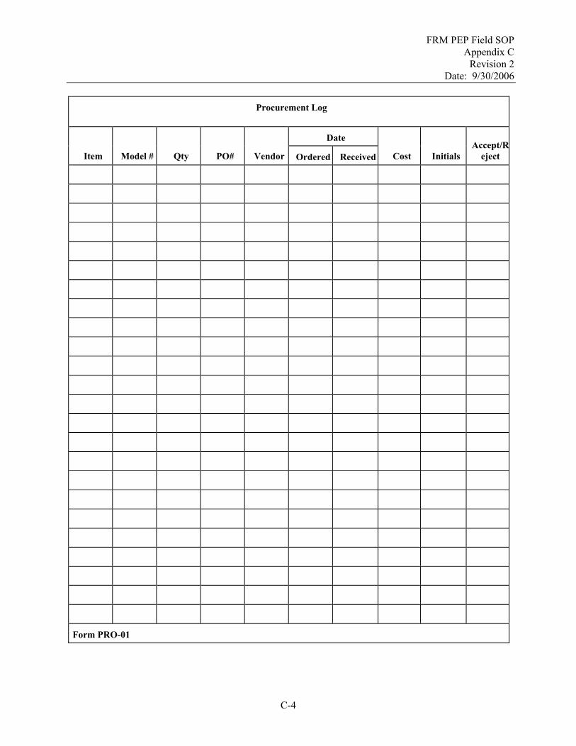
FRM PEP Field SOP Appendix C
Revision 2 Date: 9/30/2006
Procurement Log
Date
Item Model # Qty PO# Vendor Ordered Received Cost Initials Accept/R
eject
Form PRO-01
C-4

FRM PEP Field SOP Appendix C
Revision 2 Date: 9/30/2006
Phone Communication Form
Date: Time: Recorder:
Personnel on call:
Issue(s):
Decisions(s):
Follow-up Action(s):
Follow-up Responsibilities:
Completion Dates for Follow-up Actions: Form COM-01
C-5

FRM PEP Field SOP Appendix C
Revision 2 Date: 9/30/2006
Monthly Progress Report
Reporting Date: Start: End: Reporter:
Progress
Sites Scheduled for Month: Sites Evaluated during Month:
Issues
Old:
New:
Actions:
Actions:
Free Form Notes: Form COM-2
C-6

FRM PEP Field SOP Appendix C
Revision 2 Date: 9/30/2006
Site Data Sheet
AQS Site ID Site Name
Monitor ID Monitoring Freq. (1/6, 1/3, daily)
AIRS Method Designation Monitor Make/Model
Site Coordinates Lat: Long:
Site Type (SLAMS/NAMS)
Reporting Org. Address Reporting Org Contact Name Phone Number E-Mail
Directions to Site from Field Office: Directions From major thoroughfare:
Safety Concerns
Additional Equipment Needed
Closest Hospital Address and directions from site:
Closet Federal Express Facility
Closest Hardware Store:- Recommended Hotel (Address/Phone #)
Closest Monitoring Site:
2nd Closest Monitoring Site :
Free Form Notes Form SD-01
C-7

FRM PEP Field SOP Appendix C
Revision 2 Date: 9/30/2006
C-8
Form COC

FRM PEP Field SOP Appendix C
Revision 2 Date: 9/30/2006
C-9
Form FDS
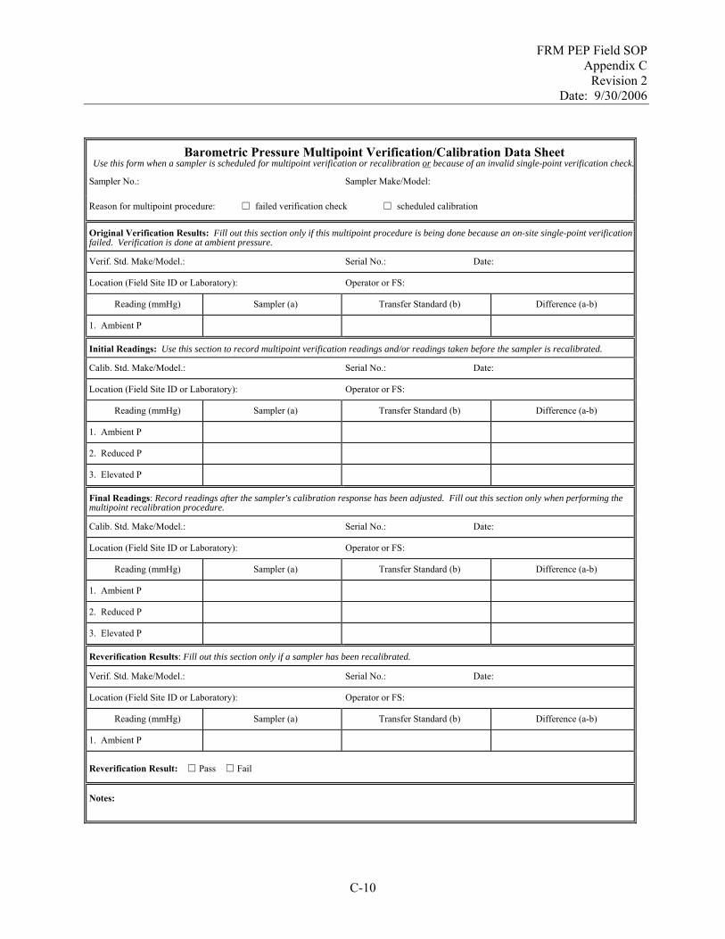
FRM PEP Field SOP Appendix C
Revision 2 Date: 9/30/2006
Barometric Pressure Multipoint Verification/Calibration Data Sheet Use this form when a sampler is scheduled for multipoint verification or recalibration or because of an invalid single-point verification check.
Sampler No.: Sampler Make/Model:
Reason for multipoint procedure: ☐ failed verification check ☐ scheduled calibration
Original Verification Results: Fill out this section only if this multipoint procedure is being done because an on-site single-point verification failed. Verification is done at ambient pressure.
Verif. Std. Make/Model.: Serial No.: Date:
Location (Field Site ID or Laboratory): Operator or FS:
Reading (mmHg) Sampler (a) Transfer Standard (b) Difference (a-b)
1. Ambient P
Initial Readings: Use this section to record multipoint verification readings and/or readings taken before the sampler is recalibrated.
Calib. Std. Make/Model.: Serial No.: Date:
Location (Field Site ID or Laboratory): Operator or FS:
Reading (mmHg) Sampler (a) Transfer Standard (b) Difference (a-b)
1. Ambient P
2. Reduced P
3. Elevated P
Final Readings: Record readings after the sampler's calibration response has been adjusted. Fill out this section only when performing the multipoint recalibration procedure.
Calib. Std. Make/Model.: Serial No.: Date:
Location (Field Site ID or Laboratory): Operator or FS:
Reading (mmHg) Sampler (a) Transfer Standard (b) Difference (a-b)
1. Ambient P
2. Reduced P
3. Elevated P
Reverification Results: Fill out this section only if a sampler has been recalibrated.
Verif. Std. Make/Model.: Serial No.: Date:
Location (Field Site ID or Laboratory): Operator or FS:
Reading (mmHg) Sampler (a) Transfer Standard (b) Difference (a-b)
1. Ambient P
Reverification Result: ☐ Pass ☐ Fail
Notes:
C-10

FRM PEP Field SOP Appendix C
Revision 2 Date: 9/30/2006
Temperature Sensor Multipoint Verification/Calibration Data Sheet
Use this form when a sampler is scheduled for multipoint verification or recalibration or because of an invalid single-point verification check. Use one form for each T sensor.
Sampler No.: Sampler Make/Model:
Reason for multipoint procedure: ☐ failed verification check ☐ scheduled calibration
Sensor Type: ☐ Ambient ☐ Filter ☐ DGM
Original Verification Results: Fill out this section only if this multipoint procedure is being done because an on-site single-point verification failed. Verification is done at ambient temperature.
Verif. Std. Make/Model.: Serial No.: Date:
Location (Field Site ID or Laboratory): Operator or FS:
Reading (deg. C) Sampler (a) Transfer Standard (b) Difference (a-b)
1. Ambient T
Initial Readings: Use this section to record multipoint verification readings and/or readings taken before the sensor is recalibrated.
Calib. Std. Make/Model.: Serial No.: Date:
Location (Field Site ID or Laboratory): Date:
Reading (deg. C) Sampler (a) Transfer Standard (b) Difference (a-b)
1. Ambient T
2. Reduced T
3. Elevated T
Final Readings: Record readings after the sensor's calibration response has been adjusted. Fill out this section only when performing the multipoint recalibration procedure.
Calib. Std. Make/Model.: Serial No.: Date:
Location (Field Site ID or Laboratory): Operator or FS:
Reading (deg. C) Sampler (a) Transfer Standard (b) Difference (a-b)
1. Ambient T
2. Reduced T
3. Elevated T
Reverification Results: Fill out this section only if the sensor has been recalibrated.
Calib. Std. Make/Model.: Serial No.: Date:
Location (Field Site ID or Laboratory): Operator or FS:
Reading (deg. C) Sampler (a) Transfer Standard (b) Difference (a-b)
1. Ambient T
Reverification Result: ☐ Pass ☐ Fail
Notes:
C-11

FRM PEP Field SOP Appendix C
Revision 2 Date: 9/30/2006
[This page intentionally left blank.]
C-12
FRM PEP Field SOP Appendix D
Revision 1 Date: 9/30/2006
Appendix D
ESAT Contacts
D-1

FRM PEP Field SOP Appendix D
Revision 1 Date: 9/30/2006
[This page intentionally left blank.]
D-2

FRM PEP Field SOP Appendix D
Revision 1 Date: 9/30/2006
Appendix D. ESAT Contacts
Name Address Phone Number Electronic Mail
ESAT
HQ ESAT PO Richard (Dan) Medlin Angela Edwards Monica McEaddy Colleen Walling
USEPA Headquarters Ariel Rios Building 1200 Pennsylvania Ave, N. W. Mail Code: 3805R Washington, DC 20460 Angela: 5202G Monica: 5106G Colleen: 5204G
(202) 564-4476 (703) 603-0263 (703) 603-0044 (703) 603-8814
[email protected] [email protected] [email protected] [email protected]
OAQPS
WAM Dennis Crumpler Michael Papp Mark Shanis Field Instrument Consultant Jeff Lantz
USEPA Office of Air Quality, Planning & Standards MQAG (D205-02) RTP, NC 27711 ** same as above ** USEPA Radiation & Indoor Environments (R&IE) P. O. Box 98517 Las Vegas, NV 89193-8517
(919) 541-0871 (919) 541-2408 (919) 541-1323 (702) 784-8275
[email protected] [email protected] [email protected] [email protected]
REGIONS
Region 1 WAM Mary Jane Cuzzupe PO Tony Palermo
USEPA-Region 1 New England Regional Lab OEME 11 Technology Dr. North Chelmsford, MA 01863
(617) 918-8397 (617) 918-8682
[email protected] [email protected]
Region 2 WAM Mark Winter PO Yolanda Guess
USEPA-Region 2 Raritan Depot (MS220) 2890 Woodbridge Ave Edison, NJ 08837-3679
(732) 321-4360 (732) 321-6606
[email protected] [email protected]
Region 3 WAM Andrew Hass PO Khin-Cho Thaung
USEPA-Region 3 1650 Arch. St. (3AP22) Philedelphia, PA 19103 USEPA-Region 3 Environmental Science Center 701 Mapes Rd. (3ES20) Fort Meade, MD 20755-5350
(215) 814-2049 (410) 305-2743
[email protected] [email protected]
D-3

FRM PEP Field SOP Appendix D
Revision 1 Date: 9/30/2006
Name Address Phone Number Electronic Mail
REGIONS
Region 4 WAM Greg Noah PO Mike Birch
USEPA Region 4 Science and Ecosystem Support Division 980 College Station Road Athens, Georgia 30605-2720 USEPA Region 4 APTMD Atlanta Federal Center 61 Forsyth St. SW Atlanta, GA 30303-3104
(706) 355-8635 (706) 355-8552
[email protected] [email protected]
Region 5 WAM Scott Hamilton PO Jay Thakkar
USEPA Region 5 77 West Jackson Blvd. (AR18J) Chicago, IL 60604-3507 ** same as above ** (Mail Code: SMF-4J)
(312) 353-4775 (312) 886-1972
[email protected] [email protected]
Region 6 WAM John Lay PO Melvin Ritter
USEPA Region 6 Laboratory Houston Branch (6PDQ) 10625 Fallstone Rd Houston, TX 77099 ** same as above ** (Mail Code: 6MDHC)
(281) 983-2155 (281) 983-2146
[email protected] [email protected]
Region 7 WAM Thien Bui PO Harold Brown
USEPA Region 7 901 North Fifth St (ENSVEMWC) Kansas City, KS 66101 ** same as above ** (Mail Code: ENSVRLAB)
(913) 551-7079 (913) 551-5127
[email protected] [email protected]
Region 8 WAM Michael Copland PO Tony Medrano
USEPA Region 8 999 18th Street (8P-AR) Suite 300 Denver, CO 80202-2466 ** same as above ** (Mail Code: 8TMSQ)
(303) 312-6010 (303) 312-6336
[email protected] [email protected]
Region 9 WAM Mathew Plate PO Rose Fong
USEPA-Region 9 75 Hawthorne St (PMD-3) San Francisco, CA 94105 ** same as above ** (Mail Code: PMD-3)
(415) 972-3799 (415) 972-3812
[email protected] [email protected]
D-4
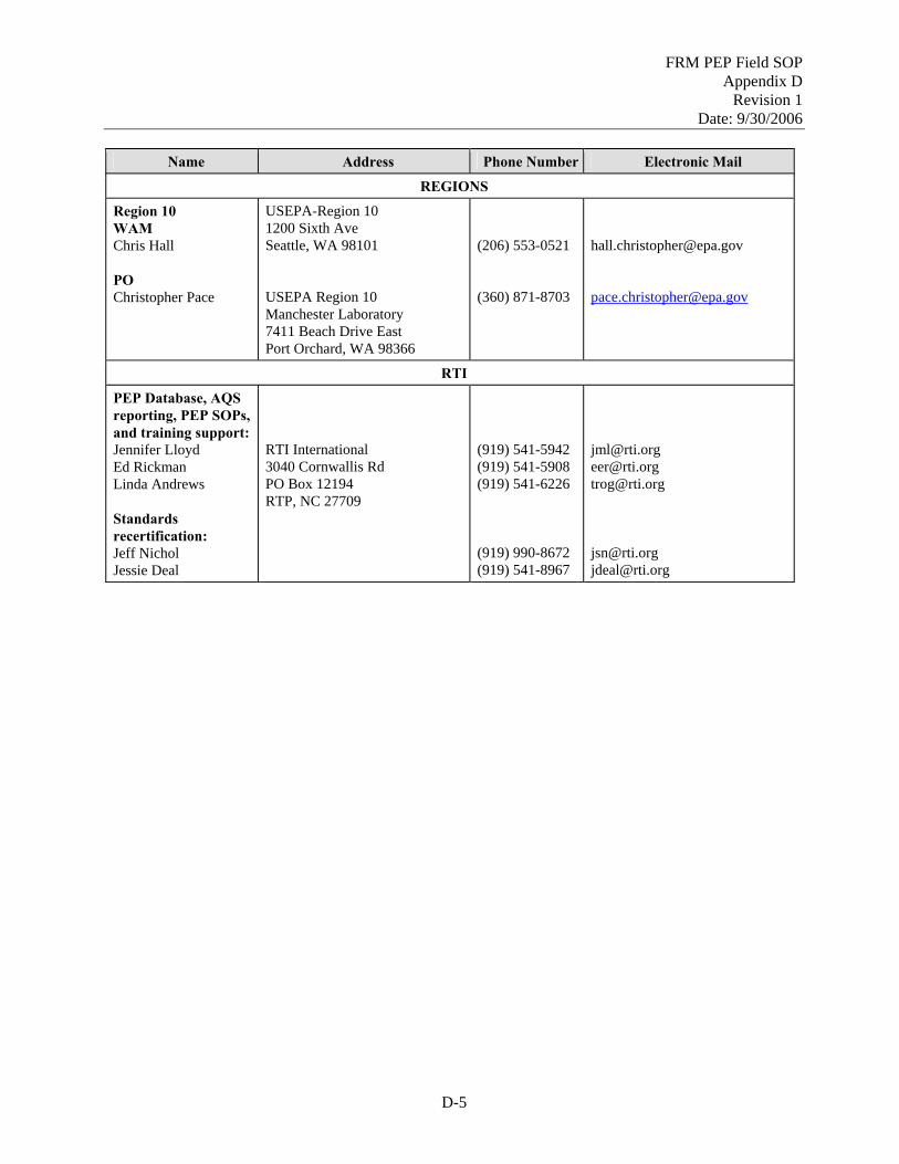
FRM PEP Field SOP Appendix D
Revision 1 Date: 9/30/2006
Name Address Phone Number Electronic Mail
REGIONS
Region 10 WAM Chris Hall PO Christopher Pace
USEPA-Region 10 1200 Sixth Ave Seattle, WA 98101 USEPA Region 10 Manchester Laboratory 7411 Beach Drive East Port Orchard, WA 98366
(206) 553-0521 (360) 871-8703
[email protected] [email protected]
RTI
PEP Database, AQS reporting, PEP SOPs, and training support: Jennifer Lloyd Ed Rickman Linda Andrews Standards recertification: Jeff Nichol Jessie Deal
RTI International 3040 Cornwallis Rd PO Box 12194 RTP, NC 27709
(919) 541-5942 (919) 541-5908 (919) 541-6226 (919) 990-8672 (919) 541-8967
[email protected] [email protected] [email protected] [email protected] [email protected]
D-5

FRM PEP Field SOP Appendix D
Revision 1 Date: 9/30/2006
[This page intentionally left blank.]
D-6

FRM PEP Field SOP Appendix E
Revision 1 Date: 9/30/2006
Appendix E
Alternate Verification Devices
E.1. Flow Rate Verification using Chinook FTS E.2. Barometric Pressure Verification using Druck 705 E.3. Temperature Verification using VWR Digital Thermometer
E-1

FRM PEP Field SOP Appendix E
Revision 1 Date: 9/30/2006
[This page intentionally left blank.]
E-2

FRM PEP Field SOP Appendix E
Revision 1 Date: 9/30/2006
Appendix E.1. Flow Rate Verification using Chinook FTS E.1.1 Scope and Applicability
NOTE: The following information is applicable to the BGI Model PQ200A portable FRM sampler and the Chinook Engineering StreamlineTM FTM Flow Transfer Standard (FTS). The Chinook device is no longer used in the PEP, but the information has been retained should the need arise for its use. Specific information herein may not be applicable to other makes and models of equipment.
Each reference or Class I equivalent PM2.5 sampler includes a specially designed sample air inlet, a size-fractionating impactor, and a sample flow rate control system. The particle size discrimination characteristics of both the inlet and the impactor are critically dependent on specific internal air velocities; a change in velocity will result in a change in the nominal particle size collected. These velocities are determined by the actual volumetric flow rate of the sampler.
In addition, the total volume of air sampled is determined from the measured volumetric flow rate and the sampling time. The mass concentration of PM2.5 in the ambient air is computed as the total mass of collected particles in the PM2.5 size range divided by the total volume of air sampled.
Therefore, in order to control the size-fractionating cutpoints and to measure the total volume correctly, the sampler’s flow rate must be maintained at a constant value that is within +4% of the design flow rate of 16.67 L/min. The flow rate of the portable FRM sampler must be verified at each site before the PE samples are taken.
E.1.2 Summary of Method
A single-point verification of the sampler flow rate is performed prior to each use of the BGI sampler in a PE. If the verification check is outside the tolerance of +4% of the indicated reading or +5% of the design flow rate (16.67 Lpm) and no reason can be found for the discrepancy, a multipoint verification/calibration of the sampler is performed (see PEPF-10).
E.1.3 Definitions
Appendix A contains a glossary of terms used in the PEP.
E.1.4 Personnel Qualifications
Personnel who conduct the FRM PEs must have passed the annual written and hands-on practical training examinations for the field component in the PM2.5 FRM PEP.
E.1.5 Cautions
# Do not operate the sampler without the verification/transport filter cassette installed. The verification/transport filter cassette should contain a clean Teflon™ filter that is free of holes, wrinkles, debris, or other defects.
# Verification of the sampler’s flow rate measurement system must be in units of the actual ambient volumetric flow rate. Do not use “mass flow rate” or “flow rate at standard conditions.”
E-3

FRM PEP Field SOP Appendix E
Revision 1 Date: 9/30/2006
# The portable FRM sampler must pass the verification checks for temperature, pressure, and
internal and external leaks before the flow verification is performed. # Verify that the flow transfer standard is properly seated on the downtube. The O-rings on the FTS
must face downward. # Keep the glass orifice of the Chinook StreamlineTM FTS clear of dust by gently scrubbing its
surfaces with a lint-free swab, moistened with isopropyl alcohol. If the glass orifice is ever chipped or broken, the entire unit must be returned to the vendor for repair and verification/calibration.
E.1.6 Equipment and Supplies
# Chinook StreamlineTM FTS and carrying case with Dwyer Series 475-0 Mark III digital manometer
OR NIST-traceable BGI Delta-Cal verification device
# Isopropyl alcohol # Lint-free swabs # Hand calculator (scientific) # Field Data Sheet # Time piece
E.1.7 Procedure
The operating flow rate of 16.67 L/min is verified before each PE. If the verification result is outside the required +4% tolerance of the indicated flow or +5% of the design flow rate, a multipoint verification/calibration at three different flow rates may be required. The one-point verification must be repeated after any three-point calibration to ensure the sampler operates properly at the design flow rate of 16.67 L/min.
E.1.7.1 Flow Rate Verification using the Chinook StreamlineTM FTS
Perform the sampler leak, temperature, and barometric pressure verification procedures, and take any corrective actions necessary to meet the acceptance criteria before performing this procedure.
1. Record the current ambient pressure (mmHg) and temperature (EC) indicated on the BGI PQ200A display screen on the Field Data Sheet.
2. Install a clean flow rate test/transport filter cassette in the cassette holder. This filter cassette should not be used for sampling, as a blank, or as a QC sample. The flow rate test/transport filter cassette may be reused at other sites provided that it remains clean and is free from any defects, such as tears, pinholes, or separation from the support ring.
3. Turn on the manometer by pressing the I/O button. Press the E/M button until the display indicates “IN WC” (inches of water column)
4. Remove the protective caps from the manometer’s air inlets. Adjust the needle valve on the top of the manometer until the water column reads “0.00”
E-4

FRM PEP Field SOP Appendix E
Revision 1 Date: 9/30/2006
5. Place the Chinook StreamlineTM FTS orifice fitting (O-ring side down) on the downtube entrance. Ensure that the fitting is fully pushed onto the downtube and fits smoothly and tightly. Connect the outlet of the orifice device to the digital manometer with flexible rubber tubing on the negative “-” inlet.
6. From the Main menu of the sampler’s control panel, use the arrow keys until the * Test and Calibration Menu flashes. Press SELECT to enter the Test menu.
7. From the Test menu, press the down arrow until * Verify Flow Calibration flashes.
8. Press SELECT. The pump will start, and the display screen will read Stabilizing Flow. Watch the display screen as the flow rate increases and stabilizes. The Check Flow Now! screen will then be displayed. Allow at least 2 minutes for stabilization. The flow rate may fluctuate or oscillate. Once the reading is considered stable, observe the high and low values of the oscillation and record the mean value flow rate on the Field Data Sheet under “Sampler FR”.
9. Use the Chinook StreamlineTM FTS device to monitor the flow rate at the inlet. Read the inches of water displaced on the electronic manometer. The manometer reading may fluctuate. Once the reading is considered stable (1 to 2 minutes), observe the high and low values of the oscillations, record the mean value flow rate on the Field Data Sheet, and solve the following FTS equation to calculate Qa, the actual flow rate. When converting units of pressure from mmHg to atms in flow calculations, the use of 4 decimal places (ex: 1.0034 atm) is recommended. All flow rates must be expressed under actual or ambient conditions, not standard conditions. NOTE: The values of “m” and “b” are specific to each FTS.
( )( )Q m
P TP
baamb
amb= ×
⎛
⎝⎜⎜
⎞
⎠⎟⎟ +
⎡
⎣
⎢⎢
⎤
⎦
⎥⎥
∆
Where
Qa = actual flow rate in liters/minute m = constant found on FTS certificate of calibration b = constant found on FTS certificate of calibration ∆P = pressure reading from manometer inches H2O Tamb = ambient temperature in Kelvins1 Pamb = ambient pressure in atmospheres2
1 Kelvin = OC + 273.15 2 1 atmosphere = 760 mmHg
E-5

FRM PEP Field SOP Appendix E
Revision 1 Date: 9/30/2006
10. After the required readings have been recorded, press the ON/OFF key to exit this function.
Press the blank (MENU) button on the BGI to return to the Main menu.
11. Calculate the flow rate as determined using the above equation and record the value in the “Std. FR (calc)” field on the Field Data Sheet.
12. Proceed to Section 5.5.7.3, below.
E.1.7.2 Flow Rate Acceptance Criteria
1. Calculate the offset or error between the flow rate indicated by the sampler readout and the calculated flow rate from the Chinook StreamlineTM FTS or Delta-Cal. The equation for percent difference (PD) is as follows:
( )PDFlow Flow
Flowsampler% =
−×
standard
standard100
2. If the calculated flow rate is outside the +4% tolerance with the BGI’s flow rate or if the sample flow rate is outside + 5% agreement with the design flow rate, the FS should ensure that the sampler and the flow rate measurement equipment are operating properly using the following steps:
Verify that all fittings and air hoses are tight and that there are no tubing kinks or obstructions.
Verify that the body of the FTS or Delta-Cal is properly seated on the downtube to prevent leakage past the O-rings that seal it to the downtube.
If using the Delta-Cal, check that flow has stabilized and ensure that the Delta-Cal has been given enough time to equilibrate to ambient conditions. Read the given flow rate provided by the Delta-Cal and record the value on the Field Data Sheet and indicate in the “m” and “b” blanks that a Delta-Cal was used.
Verify that the WINS impactor and filter holder assemblies are closed completely.
Visually inspect the sampler and the flow rate measurement equipment. Consider any other factors that might affect the flow rate measurement or the sampler operation.
After adjustments have been made, repeat the flow rate verification procedure. If the calculated flow rate and/or sample flow rate still do not meet QC criteria, the sampler must be verified/calibrated using the multipoint verification/calibration procedure as described in SOP PEPF-10, Multipoint Verifications and Calibrations.
3. Following the verification, disconnect the flow rate standard from the sampler, remove the
calibration adapter, and carefully reinstall the sampler’s inlet. Remove the filter/cassette used during the verification. If it is time to begin sampling, install a new filter cassette as described in SOP PEPF-6, Section 6.1, Conducting the Filter Exposure.
E-6

FRM PEP Field SOP Appendix E
Revision 1 Date: 9/30/2006
E.1.8 References
1. BGI Inc. 1998. PQ200A Audit Sampler, Appendix H in PQ200 Air Sampler Instruction Manual. August.
2. BGI Inc. Delta-Cal Instruction Manual. 3. U.S. EPA (Environmental Protection Agency). 1998. Monitoring PM2.5 in Ambient Air Using
Designated Reference or Class I Equivalent Methods, Section 2.12 in Quality Assurance Handbook for Air Pollution Measurement Systems, Volume II, Part II. April draft.
4. 40 CFR Part 50, Appendix L, Section 9.2. 5. Chinook Engineering. Chinook StreamlineTM FTS data sheet.
E-7
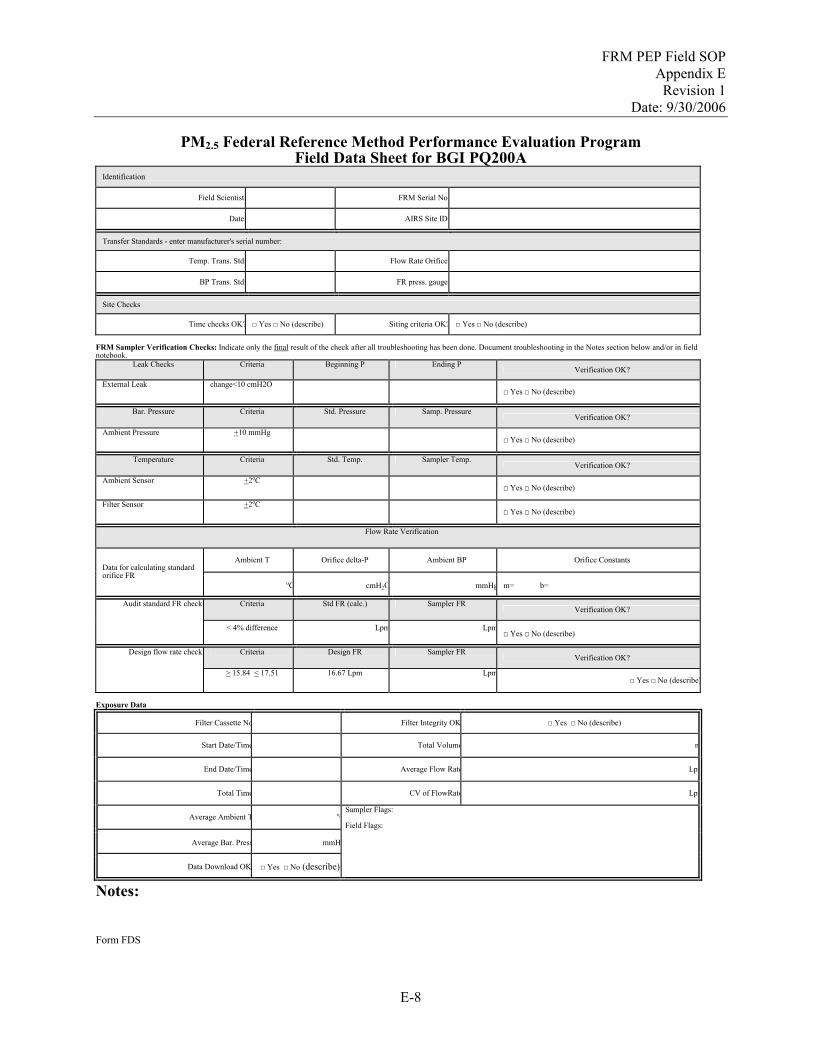
FRM PEP Field SOP Appendix E
Revision 1 Date: 9/30/2006
PM2.5 Federal Reference Method Performance Evaluation Program
Field Data Sheet for BGI PQ200A Identification
Field Scientist: FRM Serial No:
Date: AIRS Site ID:
Transfer Standards - enter manufacturer's serial number:
Temp. Trans. Std: Flow Rate Orifice:
BP Trans. Std: FR press. gauge:
Site Checks
Time checks OK? □ Yes □ No (describe) Siting criteria OK? □ Yes □ No (describe)
FRM Sampler Verification Checks: Indicate only the final result of the check after all troubleshooting has been done. Document troubleshooting in the Notes section below and/or in field notebook.
Leak Checks Criteria Beginning P Ending P Verification OK?
External Leak change<10 cmH2O □ Yes □ No (describe)
Bar. Pressure Criteria Std. Pressure Samp. Pressure Verification OK?
Ambient Pressure +10 mmHg □ Yes □ No (describe)
Temperature Criteria Std. Temp. Sampler Temp. Verification OK?
Ambient Sensor +2oC □ Yes □ No (describe)
Filter Sensor +2oC □ Yes □ No (describe)
Flow Rate Verification
Ambient T Orifice delta-P Ambient BP Orifice Constants Data for calculating standard orifice FR
oC cmH2O mmHg m= b=
Criteria Std FR (calc.) Sampler FR Verification OK?
Audit standard FR check:
< 4% difference Lpm Lpm□ Yes □ No (describe)
Criteria Design FR Sampler FR Verification OK?
Design flow rate check:
> 15.84 < 17.51 16.67 Lpm Lpm□ Yes □ No (describe)
Exposure Data
Filter Cassette No Filter Integrity OK □ Yes □ No (describe)
Start Date/Time Total Volume m
End Date/Time Average Flow Rate Lpm
Total Time CV of FlowRate Lpm
Average Ambient T oC
Average Bar. Press mmH
Data Download OK □ Yes □ No (describe)
Sampler Flags: Field Flags:
Notes: Form FDS
E-8

FRM PEP Field SOP Appendix E
Revision 1 Date: 9/30/2006
Appendix E.2. Barometric Pressure Verification using Druck 705
E.2.1 Scope and Applicability
NOTE: The following information applies only to the BGI Model PQ200A portable FRM sampler and specified verification devices. Specific information herein may not be applicable to other makes or models of equipment.
This section applies to verifying the barometric pressure measurement system of the BGI PQ200A Portable PM2.5 Sampler. Operations covered in this SOP include routine functional check procedures for the pressure measurement system.
E.2.2 Summary of Method
The BGI PM2.5 sampler has a built-in atmospheric pressure sensor. The sensor’s output is processed to allow control of the sampling flow rate to the design value of 16.7 L/min under actual ambient conditions of temperature and pressure.
To perform a routine verification, the barometric pressure sensor reading is verified at ambient pressure through comparison with the reading from an external standard of known accuracy. If a pressure difference of more than 10 mmHg is observed, a multipoint verification/calibration of the pressure-sensing and display system is required before the FRM sampler may be used to perform an evaluation.
E.2.3 Definitions
Appendix A contains a glossary of terms used in the PEP.
E.2.4 Personnel Qualifications
Personnel who conduct the FRM PEs must have passed the annual written and hands-on practical training examinations for the field component in the PM2.5 FRM PEP.
E.2.5 Cautions
# Protect all types of barometers from mechanical shock and sudden changes in pressure. A barometer subjected to either of these events must be verified by comparing it to a laboratory mercury column barometer (or other NIST-traceable standard). If required, the barometer would either be adjusted, or an offset correction would be established.
# Minimize the vertical and horizontal temperature gradients across the barometer and avoid direct sunlight, drafts, and vibrations.
# Barometers should be allowed some time to adjust to temperature and pressure differences. During transport and assembly of the instrument, transport the barometer to the sampling platform so that it may equilibrate for an hour before use.
# At high altitudes, verification of FRM barometric pressure may be difficult due to significantly lower pressure. The FS should use all available information, including state/local FRM barometric pressure readings and/or readings from other samplers. The FS may also check with local airport or
E-9

FRM PEP Field SOP Appendix E
Revision 1 Date: 9/30/2006
local airport or weather station. The FS should document all of this extra information on the FDS.
E.2.6 Equipment and Supplies
The following equipment and materials are required for barometric pressure verification checks:
# BGI PQ200A sampler
# Field Data Sheet
# Portable, NIST-traceable barometer for field barometric pressure verifications (Druck digital absolute pressure indicator, Model No. DPI 705)
E.2.7 Procedure
E.2.7.1 Field Verification of Barometric Pressure System using the Druck 705
The FRM sampler’s barometric pressure sensing system is verified by comparing the sampler reading to that of the portable barometer at ambient conditions, as described in the following steps:
1. Unpack, install, and power the sampler at the site, as described in SOP PEPF-4, Transportation of the Sampler and Installation at the Site, and in Section 5.1 of this PEPF.
2. Unpack the portable barometer transfer standard and place it near the sampler. Allow time for the verification equipment to equilibrate to ambient conditions. Turn on the power and set the readout units and operating mode as follows:
• Set the portable barometer to read in units of “mmHg” (also known as “Torr”).
• Set the portable barometer to operate in the “absolute” pressure mode, not “gauge” or “differential” pressure mode. (NOTE: On the “absolute” scale, the ambient atmospheric pressure should usually be between 600 and 760 mmHg, depending on altitude. If the barometer’s reading is zero, or close to zero, it is likely that it is set to “gauge” or “differential” mode.)
3. Record the pressure readings from the sampler (Sampler Pressure) and the portable barometer (Std. Pressure) on the Field Data Sheet (App C).
4. If the two readings are within 10 mmHg of each other, the verification of the portable FRM monitor’s pressure sensor is satisfactory. Carefully pack up the portable barometer transfer standard and continue with the remaining verification procedures.
5. If the deviation is greater than 10 mmHg, check the barometric pressure using a backup verification device. If the results are similar to the primary verification device, then the sampler’s pressure measurement system may be damaged and should be serviced. A multipoint verification/calibration procedure should be performed (see SOP PEPF-10, Multipoint Verifications and Calibrations). A replacement portable sampler must be installed at the site.
E-10

FRM PEP Field SOP Appendix E
Revision 1 Date: 9/30/2006
E.2.8 References
1. BGI Inc. 1998. PQ200 Air Sampler Instruction Manual, “Appendix H - PQ200A Audit Sampler.” August/
2. U.S. EPA (Environmental Protection Agency). 1998. Monitoring PM2.5 in Ambient Air Using Designated Reference or Class I Equivalent Methods, Section 2.12 in Quality Assurance Handbook for Air Pollution Measurement Systems, Volume II, Part II. April draft.
3. SPK Druck User’s Manual for the digital absolute pressure indicator, Model DPI 705.
E-11

FRM PEP Field SOP Appendix E
Revision 1 Date: 9/30/2006
Appendix E.3. Temperature Verification using VWR Digital Thermometer E.3.1 Scope and Applicability
This section applies to verifying the temperature measurement system for the FRM PE sampler. Operations covered in this SOP include verification checks for the two temperature sensors in the BGI PQ200A unit.
E.3.2 Summary of Method
Ambient and filter temperature sensors are each verified at a single point using an external temperature standard of known, NIST-traceable accuracy. If an excessive difference is observed, a multipoint verification/calibration of the temperature sensor may be required (see SOP PEPF-10, Multipoint Verifications and Calibrations).
E.3.3 Definitions
Appendix A contains a glossary of terms used in the PEP.
E.3.4 Personnel Qualifications
Personnel who conduct the FRM PEs must have passed the annual written and hands-on practical training examinations for the field component in the PM2.5 FRM PEP.
E.3.5 Cautions
# Be sure that the temperature reference standard used to verify the instrument’s sensors has been calibrated against a NIST-certified standard within the prescribed time period (annually).
# Due to frequent assembly and disassembly of the portable samplers, the ambient temperature probe’s connecting pins may be damaged. Care must be taken at installation when connecting the pins to the main unit.
# Care must be observed when placing the thermometer’s probe through the gill screen to avoid any damage to the screen or probe.
# Temperature verification device probe should not be placed in direct sunlight during equilibration and verification.
E.3.6 Equipment and Supplies
# BGI PQ200A air sampler
# VWR digital thermometer, # 61220-601, NIST-traceable, with probe
# Field Data Sheet
# Timepiece
E-12

FRM PEP Field SOP Appendix E
Revision 1 Date: 9/30/2006
E.3.7 Procedure
The response of two temperature sensors (ambient temperature and filter temperature) must be verified each time the BGI PQ200A portable sampler is set up at a new location.
E.3.7.1 Single-Point Field Verification in Ambient Air using the VWR digital thermometer
To perform a single-point field verification of temperature for the BGI PQ200A, conduct this temperature verification test after the sampler is assembled and in place on the site. Proceed as follows:
1. It is best if the sampler has been on the site for at least 1 hour to allow adequate time for the ambient and filter temperature sensors to reach temperature equilibrium with their surroundings; however, equilibration may occur in less than an hour. The FS should use his or her best judgment to ensure that all temperature sensors are equilibrated to ambient conditions.
2. Place the digital verification thermometer in the same general location as the portable sampler. Verify that the digital thermometer is influenced by the same environmental conditions as the portable sampler.
3. Turn on the sampler and display the Main screen. The current temperature and pressure should be displayed. It is not necessary for the sampler pump to be running.
4. Carefully insert the digital thermometer’s sensor probe an inch or two into the space between the louvers of the gill screen that enclose the ambient temperature sensor so that the probe tip is in close proximity to the ambient sensor.
Wait until the digital thermometer’s reading is stable and compare it to the ambient temperature reading displayed on the Main screen. If the temperatures agree within ± 2EC, the ambient temperature sensor response is acceptable. If not, skip to Step 9, below.
5. Remove the sensor probe from the gill screen, and record the temperature information on the Field Data Sheet (App C).
6. Open the door of the main unit, open the filter holder assembly, remove the cassette, and place in clean location.
7. Place the digital thermometer’s sensor probe tip within ~1 cm of the filter temperature sensor in the bottom portion of the filter assembly.
8. Allow the thermometer’s reading to stabilize and compare the reading to the one displayed on the Main screen for the filter temperature. If the temperatures agree within ± 2EC, the filter temperature sensor response is acceptable (proceed to Step 11). If the sensor response is not acceptable, go to Step 9.
9. If the two readings are outside acceptance criteria, wait longer (10 to 15 minutes) for temperature equilibration to occur, and repeat the procedure. If the readings still do not agree, verify that the problem is not with the digital verification thermometer. If the problem is not
E-13

FRM PEP Field SOP Appendix E
Revision 1 Date: 9/30/2006
with the verification thermometer and the FS does not feel the problem can be rectified, replace the portable sampler with a spare sampler.
NOTE: If the reporting organization operator is at the site, he/she may be able to check the routine monitor’s temperature sensors. If they are in agreement with the readings from the FRM PEP portable sampler, this may indicate a problem with the digital verification thermometer. If there is agreement, the portable sampler can be used. It is important to indicate the verification problem on the Field Data Sheet and proceed with troubleshooting the verification thermometer.
10. Remove the thermometer probe from the sampler. Return the filter assembly to its normal configuration.
11. Record information on the verification form.
E.3.8 References
1. BGI Inc. 1998. PQ200A Audit Sampler, Appendix H in PQ200 Air Sampler Instruction Manual. August.
2. VWR, Inc. Traceable® Digital Thermometer Instruction leaflet.
3. U.S. EPA (Environmental Protection Agency). 1998. Monitoring PM2.5 in Ambient Air Using Designated Reference or Class I Equivalent Methods, Section 2.12 in Quality Assurance Handbook for Air Pollution Measurement Systems, Volume II, Part II. April draft.
E-14