quality assurance guidelines in nhai works
DESCRIPTION
Quality Assurance Guidelines in NHAI WorksTRANSCRIPT

D.V.Bhavanna Rao. M.Tech., F.I.E.,Chief Engineer ,
Roads & Buildings Andhra Pradesh (Retired)
for more presentations on Roads and Bridges, please visit
http://[email protected]
Quality Assurance Guidelines inNational Highway Authority of India works

NHAI Head Office
CGM / GM Headquarters(in charge of project
Project Implementation Unit(at the site0
Supervision Consultant
Quality Audit
Supervision Consultant(Engineer)
Team Leader(Engineer’s Representative)
Planning&
Monitoring
Contract Management
Engineer
Specialists:Survey
HighwayMaterials & PavementBridges
Quality Assurance &
Quality Control
Unit

Duties and Responsibilities
In most of the NHAI contracts, the NHAI is the “Employer”and the Supervision Consultant is the “Engineer”. The latte rappoints a Team Leader, who is designated as the “Engineer’sRepresentative”. The Engineer’s Representative performs variousduties and is delegated authority in terms of various clause s ofthe Contract. The Engineer’s Representative may appoint aResident Engineer (RE) for each construction package. TheConstruction Supervision Manual shall lay down the functio ns tobe exercised by the Engineer, Engineer’s Representative andbe exercised by the Engineer, Engineer’s Representative andResident Engineer.
In the supervision of works, a typical road packageinvolves the services of senior professional staff and supp ortstaff.
It is necessary that the duties and responsibilities of eachof these are clearly understood and specified. These duties andresponsibilities may vary from job to job, and should be clea rlylaid down for each project. The exact duties and responsibil itiesfor each job shall be prepared by the Supervision Consultant .

Methods Statement
Prior to the commencement of important item of work and activ ity(which may be listed by the Engineer and given to the Contract or), theContractor is required to submit for approval by the Residen t Engineer a“Methods Statement”, which describes the methodology as to ho w he (theContractor) plans to carry out that item of work/activity in accordance withthe Specifications. The Methods Statements shall be develo ped to a degree ofdetail depending upon:(a) The intricacy of operations for carrying out the propose dconstruction activity;(b) The extent to which the methodology is detailed out in the(b) The extent to which the methodology is detailed out in theSpecifications.
The Methods Statement shall describe the equipment to the de ployed(size/number/capacity), the sequence of operations, field trials if any areinvolved, design of mixes, job-mix-formulae, temporary wo rks erection andlaunching, traffic management plan, safety precautions, e nvironmentalprotection measures etc.
The Methods to be furnished by the Contractor in respect of ea chmajor activity shall be step-wise sequencing of tasks, and s hould be detailedand meaningful. The Engineer shall either straightway give his consent or askfor modification before acceptance.

Method Statement for Major Earthwork Operations
1. Tests for borrow area soils2. Type and number of excavation plant and transport ation
machinery and their anticipated outputs3. Method of working in cut and fill sections4. Type and number of spreading plant for filling an d
anticipated outputs
5. Type and number of compaction plant and anticipat edOutputs
6. Testing and layer approval7. Method of working for site clearance and dealin g with
trees and vegetation
8. Setting out and control of levels and batters9. Details of disposal areas for unsuitable materi al10.Details of suitable borrow areas for imported fi ll
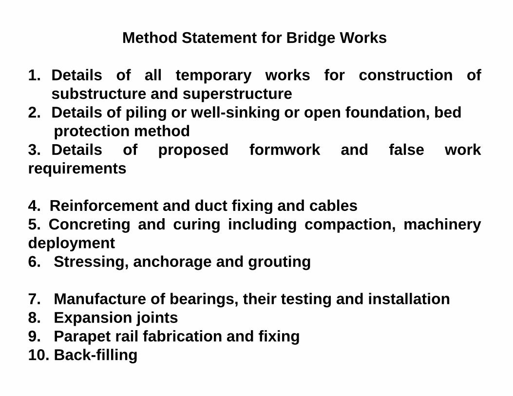
Method Statement for Bridge Works
1. Details of all temporary works for construction ofsubstructure and superstructure
2. Details of piling or well-sinking or open foundation, bedprotection method
3. Details of proposed formwork and false workrequirements
4. Reinforcement and duct fixing and cables4. Reinforcement and duct fixing and cables5. Concreting and curing including compaction, machinerydeployment6. Stressing, anchorage and grouting
7. Manufacture of bearings, their testing and installation8. Expansion joints9. Parapet rail fabrication and fixing10. Back-filling

Method Statement for Fixing of PTFE cum POT Bearing
1. Manufacturer of the bearings2. Date of supply of the bearings3. Expected date of installation4. Precise sequence of operations such as
preparation of pockets, placements of sleeves,preparation of pockets, placements of sleeves,placement and aligning of bearing, grouting,tightening of bolts etc.
5. Likely difficulties which may be faced andcorrective measures
6. Location where the bearing was tested7. Manufacturer’s warrantee period
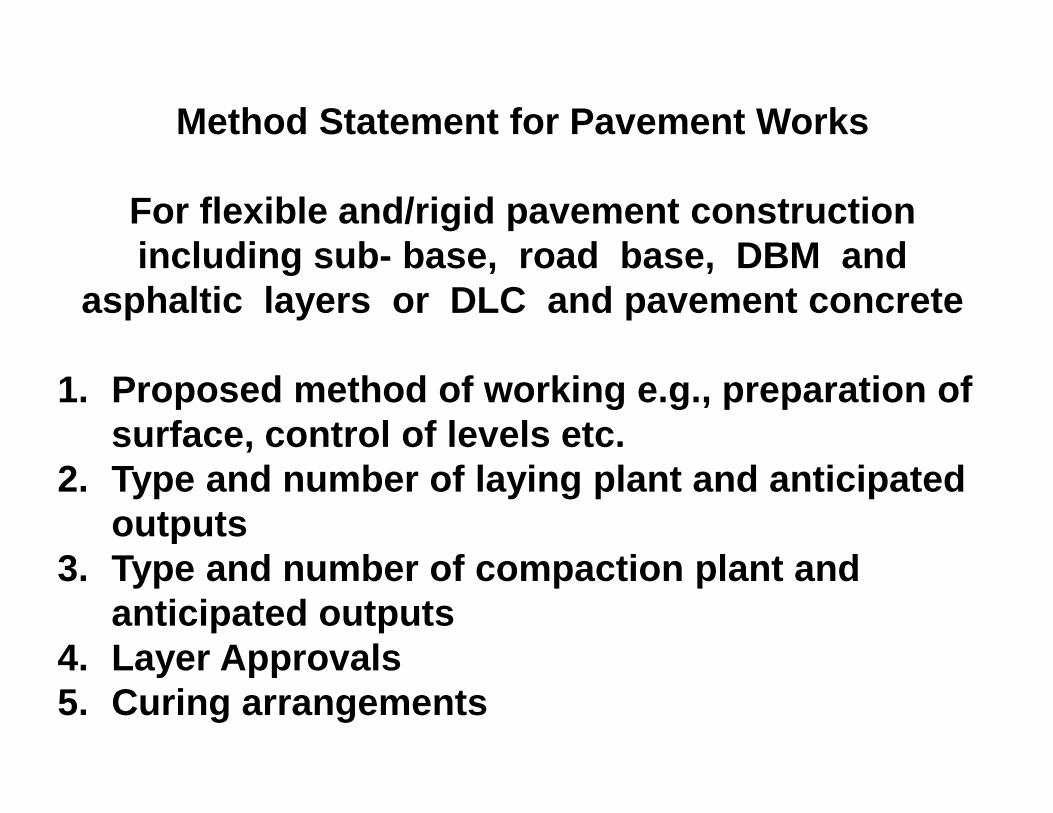
Method Statement for Pavement Works
For flexible and/rigid pavement construction including sub- base, road base, DBM and
asphaltic layers or DLC and pavement concrete
1. Proposed method of working e.g., preparation of 1. Proposed method of working e.g., preparation of surface, control of levels etc.
2. Type and number of laying plant and anticipated outputs
3. Type and number of compaction plant and anticipated outputs
4. Layer Approvals5. Curing arrangements
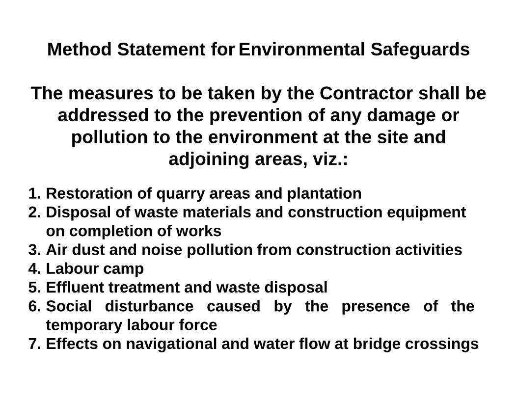
Method Statement for Environmental Safeguards
The measures to be taken by the Contractor shall be addressed to the prevention of any damage or
pollution to the environment at the site and adjoining areas, viz.:
1. Restoration of quarry areas and plantation1. Restoration of quarry areas and plantation2. Disposal of waste materials and construction equi pment
on completion of works3. Air dust and noise pollution from construction ac tivities4. Labour camp5. Effluent treatment and waste disposal6. Social disturbance caused by the presen ce of the
temporary labour force7. Effects on navigational and water flow at bridge crossings

Method Statement for Temporary Traffic Diversions and Traffic Crossings
1.Details of any temporary traffic diversions thatmay be required in order to execute the workssafely
2.Proposed length of diversion2.Proposed length of diversion3.Duration of operation of diversion4.Constructional details of diversion including
signage5.Details of proposed traffic management,
including liaison with the police and concernedauthorities

Method Statement for Concrete Production and Transport
Detail proposed set-up for the production and transport of concrete
1.Location and layout of batching plants1.Location and layout of batching plants2.Details of plant size, type and estimated outputs3.Details of cement storage and handling4.Details of aggregate stockpiles and storage
capacities5.Details of water supply and chilling
arrangements6.Details of proposed transport of concrete

Method Statement for Asphaltic Concrete Production and Transport
Detail proposed set-up for the production and transport of asphaltic and bitumen paving products
1.Location and layout of asphalt plant2.Details of plant size, type and estimated outputs3.Details of aggregate stockpiles, handling etc.4.Details of bitumen storage, heating facilities et c. 5.Details of proposed transport of mixed materials 6.Dust nuisance.

Method Statement for Quarrying and Crushing Operations
Detail proposed set-up for production of aggregates and other stone products to be incorporated in the
works:
1.Location of proposed quarry1.Location of proposed quarry2.Details of proposed method of operation of quarry
i.e., development and operation of quarryface, outputs etc.
3.Details of proposed plant installations giving typeand size of main items and layout of crushingoperations showing production flow through tofinal products.
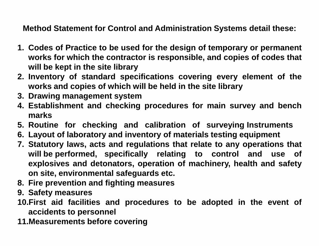
Method Statement for Control and Administration Syst ems detail these:
1. Codes of Practice to be used for the design of temporary or p ermanentworks for which the contractor is responsible, and copies of codes thatwill be kept in the site library
2. Inventory of standard specifications covering every ele ment of theworks and copies of which will be held in the site library
3. Drawing management system4. Establishment and checking procedures for main survey an d bench
marks5. Routine for checking and calibration of surveying Instruments5. Routine for checking and calibration of surveying Instruments6. Layout of laboratory and inventory of materials testing e quipment7. Statutory laws, acts and regulations that relate to any op erations that
will be performed, specifically relating to control and use ofexplosives and detonators, operation of machinery, health and safetyon site, environmental safeguards etc.
8. Fire prevention and fighting measures9. Safety measures10.First aid facilities and procedures to be adopted in the e vent of
accidents to personnel11.Measurements before covering

Contractor’s Works Programme
Based on deadlines specified in the Contract, the Contracto r isrequired to submit a Works Programme to be approved by the Eng ineerthat provides for completion of the Works in accordance with thesedeadlines. Approval of the programme by the Engineer shall b e givenbased on completeness (i.e., includes all activities) and a ccuracy(activities are properly sequenced) of the proposal, and on comparisonof total output of the Contractor’s scheduled mobilized equ ipment withthe types and actual quantities of works scheduled to be comp letedduring each month of the specified construction period. An a dditionalcheck shall be made to ensure that outputs for relevant activities arecheck shall be made to ensure that outputs for relevant activities arereduced realistically during the monsoon period.
Following approval of the Contractor’s initial Works Progr amme,the programme is reviewed periodically in order to appraise the need forchanging the proposed scheduling of activities to be in line with actualconstruction progress. In the case where deviations from th e proposedschedule are significant enough to raise concern with regar d to theContractor’s to complete the woks on time, the Contractor is to berequired to provide an acceptable revised programme to catc h-up andmeet the original deadline requirements (i.e. he may need to mobilizeadditional equipment, or work additional hours per week etc .).

Submittal of Approved Design Drawings
(a) The Engineering Design Drawings approved by the Employe r(i.e. the tender drawings) are first to be reviewed by theSupervision Consultant’s Design Review Team with regard toaccuracy and completeness, and he will makerecommendations, additions, etc. to be carried out for the d esigns.(b) Following completion of the incorporation of any revisi ontogether with any further required drawings instructed by t heEmployer, the Employer is to approve the revised drawings andEmployer, the Employer is to approve the revised drawings andissue them to the Team Leader for submittal to the Contractor s. Alldrawings are to be signed and transmitted officially.(c) The Contractor will then be issued with two sets of approv edconstruction drawings which have been marked “Approved forConstruction” and signed and dated. A register of drawings i ssuedshall be maintained.(d) To expedite start of the work, the drawings may be issued i ngroups rather than as a complete set, and / or only parts of spe cificdrawings may be approved for construction at any one time.

Priorities for Preparation of working Drawings
In allocating priorities for working drawing preparation, the following aspects are to be taken
into account.
(a) Contractor’s approved construction programme and construction sequenceand construction sequence
(b) Delivery times for construction material
(c) Fabrication times for manufactured items
(d) Any design work or shop drawings required from the Contractor.

Review, Revision and Recording of Drawings
(a) The Engineer’s representative and/or the Resident Engi neer willreview the drawing and note any drawings inconsistent withcontractual obligations.(b) All drawings issued to the Contractor will first be check ed by theResident Engineer for variations implications from the Sco pe ofWorks or departures from the Specifications. The results of this checkwill serve to initiate, if necessary, the appropriate proce dure for issueof a Variations Order.(c) If necessary, the Engineer’s Representative will liaise with the(c) If necessary, the Engineer’s Representative will liaise with thedesigner to ensure the designer is aware of any drawing that i sinconsistent with the contractual obligations or that may g ive rise to avariation. This will give the designer the opportunity to re consider orconfirm the revised drawing prior to issue to the Contractor .(d) When any drawing is revised, copies of the revised drawin gsshould be issued to the Contractor with the revision clearly marked.(e) After issue of drawings to the Contractor, the Contracto r’sAdministration Engineer will update the master set of drawi ngs andDrawings Issue Register

Site Inspections
To ensure the Contractor’s strict contact compliance, it is mandatory thatall personnel charged with inspection responsibilities pr operly preparethemselves in advance through detailed study and understan ding of the Plansand Specifications. On-site observations of the field engi neer’s activities andprocedures will be made by the RE to ensure compliance with pl ans andSpecifications.
Field engineers are authorized to inspect all work done and ma terialfurnished. Such inspection will extend to all parts of the wo rks and to thepreparation, fabrication or manufacture of the materials t o be used. The fieldengineers are not authorized to alter or waive any provision of the contractconditions or documents.
The Highway Engineer is responsible for keeping his Residen t Engineerinformed as to progress of the work and the manner in which it i s being done, andalso to call the Contractor’s attention to any non-complian ce with the drawings orspecifications. He is not authorized to approve or accept any portion of the work,or to issue instruction contrary to the plans and specificat ions, or to act on behalfof the Contractor. The field engineers have authority to rej ect unsatisfactoryworkmanship, defective materials and to recommend suspens ion of any work thatis being improperly performed, subject to approval by the Re sident Engineer andor the Team Leader. The field engineers may exercise such add itional authorityonly as may, from time to time delegated to them by the Residen t Engineer and/oras approved by the Team Leader.

Daily Inspection ReportsA Daily Report must be completed by each field
engineer. These daily Reports will be reviewed and compiledby the RE and will constitute part of the final Projectdocumentation submitted to NHAI.
The Daily Report from each field engineer must incl ude but not be limited to the following items:
(a) Quantities of work performed under their inspec tion, such as cubic meters of material acceptably placed etc.;(b) Site instructions given;(b) Site instructions given;(c) Unusual or unsatisfactory conditions; (d) Delays encountered;(e) Number of men or man-hours employed;(f) Equipment, Plant, methods used by the Contracto r;(g)Tests performed to satisfy quality control, and as samples taken;(h) Weather conditions and effect on the works; (i) Day work records, if any.

Field Inspection DiariesEach field engineer will keep personnel Diary
Notebook to accumulate during the day all data used to prepar ehis Daily Report. Notes made in their Diary Notebook will berecorded neatly, clearly and will be dated, signed and in suf ficientdetail to be clearly understood. This Diary Notebook will al soinclude the field engineer’s working hours and work locatio ndetails for each day.
The field engineer’s Diary Notebook must be properlyidentified, indexed and periodically turned in to the RE for hisreview and safe-keeping . At the end of the Project these Diaryreview and safe-keeping . At the end of the Project these DiaryNotebooks will be returned to each field engineer.
The field engineer’s Daily Report will contain quantities o fwork satisfactorily performed each day under their inspect ion.These quantities will be based on measurements if the quanti ty isfor a particular section of work that is complete or based on a nestimate if the work is on going. Sketches with dimensions an dcalculations should be attached to the Reports as required.
Mechanical Plant and Equipment should be inspectedperiodically.

QUALITY ASSURANCE PLAN
The Quality Assurance Plan (QAP) is themethodology that is selected for ensuring that theproject incorporates all elements that are needed forthe successful design, construction andthe successful design, construction andmaintenance of a project. Since projects vary inscope, the QAP has to be project-specific. The QAPshould deal with all aspects of selection and testingof materials, acceptance criteria, guidelines fornon-conforming materials and works anddocumentation.

Quality Control
One of the most important tasks of the supervision during the executionof a road contract is technical quality control, i.e. contro l as to whether thematerials and work supplied by the Contractor meet the techn ical requirements inthe contract specifications. There are two types of quality control, which aredescribed below:
(a) Control of MethodsMethod control is usually carried out by the Consultant`s fi eld staff
whose job it is to be on the site and supervise the Contractor d uring the executionof the works . At the same time the field staff will perform simple measurements,of the works . At the same time the field staff will perform simple measurements,such as the recording of the thickness of fill layers, the tem perature of asphaltmaterial, and the slump of cement concrete.
(b) Control of End-ResultsEnd-result control includes field tests e.g. control of the evenness of
completed pavement layers and laboratory tests, e.g. Marsh all tests on asphaltmaterials. Other tests are a combination of field and labora tory tests. An exampleof this is the compaction control of earthworks where the ach ieved density isdetermined by means of a field test, and where the IS/ AASHTO d ensity with whichthe result should be compared is found by means of a laborator y test. End-resultscontrol is carried out by laboratory technicians, and most o f the work consists oflaboratory tests.

Testing Facilities
Before the Contractor initiates earthworks, asphaltpaving, concrete works etc., the corresponding test facili tiesmust be available, i.e.
(a) Laboratories must be built and equipped;(b) Laboratory equipment must be procured and tested;(c) Test forms must be prepared; and(d) Laboratory technicians must be employed and trained.
The Contractor may also get the tests carried out inrecognized testing laboratories outside for tests of a speci alnature not covered by the equipment indicated in Appendix II Iof QA Manual. Such testing must be preceded by approval ofthe Engineer. The testing equipment must be regularlyserviced as recommended by the suppliers. A calibrationchart must be available for each equipment.

Monitoring of Quality ControlThe Engineer has the authority and responsibility for
monitoring the use of the Quality Control System and for ensu ringthat the above policies are being implemented, and to consid er theneed for changes.The contractor is required to carry out and is responsible fo r:• Sampling and testing• Measurements
But the obligations of the Contractor do not relieve theEngineer /the Resident Engineer of their duties towards theEmployer :Employer :(a) The Engineer shall carry out such duties in issuing• Decisions• Certificates• Ordersas specified in the contract.(b)The Engineer / the Resident Engineer’s contractual duti es are to• Watch and supervise the works• Test and examine materials and workmanship• Exercise “process control” wherever needed

Resident Engineer assisted by qualified and adequate staffmust carry out supervision and control such as:• Sub-soil investigations• Inspection of works and workmanship• Geometric control and measurements• Quality control of works and materials
The Resident Engineer’s staff may be divided into categorie s sothat the supervisory organization is made up of bodies with t heir ownfield of responsibility such as:• Structures• Structures• Highway• Materials and laboratory
It is naturally of great importance that each field of respon sibilityworks in a competent and well-organised manner. It is just as important,however, that all the fields of responsibility of the organi zation work welltogether, so there does not appear any “no man’s land” betwee n therespective fields of responsibility. Designated areas of i ndividualresponsibility should keep close contact with other member s of the teamso that information on faulty workmanship etc. is passed on t o the peopleresponsible.

Approval of Quarries and Borrow Areas
The Contractor is to obtain approval from the MaterialEngineer through the Resident Engineer for each Quarry andBorrow Area to be used in the project prior tocommencement of quarrying and/or borrow area excavationactivities. The primary considerations to be considered bythe Engineer in granting approval are:1. The proposed materials meet specification requirements2. The Contractor has legal approval by the owner to
excavate/remove materials from the proposedquarry/borrow area
3. The Contractor submits an acceptable “EnvironmentalManagement Plan” for development; use and closingdown of the proposed quarry/borrow area, together withany other approvals or documents that may be requiredfrom the Ministry of Environment and Forests or otherconcerned authorities.

Steps to be followed for approval of each Quarry/Bo rrow Area
1. The Contractor is to complete the “Materials Sources Data” form givingdetails regarding size, location, orientation and access fo r the proposedquarry/borrow area (rough map to be drawn). Also to be includ ed are thelist of materials to be sourced for the project works (e.g. em bankment,GSB, WMM etc.), and the estimated quantities for these mater ials.
2. The results of laboratory tests conducted on the material s jointlysampled with the Consultant’s Material Engineer (or his des ignatedrepresentative) are to be summarized on the approval form, an dcomplete copies of all tests are to be attached to the form.
3. The Contractor is to attach to the completed “Materials Sources Data”3. The Contractor is to attach to the completed “Materials Sources Data”form, a letter, or some other form of written acknowledgemen t, thatindicates that the owner of the quarry/borrow area agrees to theContractor removing the proposed types and quantities of ma terialsindicated in the form.
4. The Contractor attaches to the completed “Material Sourc es Data”form, his proposed “Environmental Management Plan” for deve lopment,use and closing down of the proposed quarry/ borrow area. Pho tographsof the sources site, including access roads, etc. should be i ncluded withthe proposal so that the base line conditions of the Quarry/B orrow Areato be clearly established

Development/Redevelopment of Borrow Pits and Quarri es
1. Both during and following completion of the excavationactivities in the borrow areas, the Engineer, together with theEnvironmental Officer, are to inspect the areas to ensurethat the borrow pits and access roads are properly graded anddrained to ensure minimum erosion, and to prevent run-off fr omeither collecting or from damaging adjacent properties. Al lexisting trees within the boundary of the quarry/borrow are asshould be preserved and protected .should be preserved and protected .
2. Temporary stockpiles of blasted quarry materials andborrow areas soils are to be located so as to ensure smoothflow of traffic within the areas and for access to main roads, andare to be designed so as to minimize contamination anddamage from rainfall/run-off etc.
3. Borrow Areas (except in cases where the landowner has agre edthat the borrow pit is to be excavated so as to form anappropriate pond for agricultural purpose), will be redeve lopedby filling and providing 150 mm thick layer of preserved tops oil.The contractor is to also replace any vegetation removed.

Approval of Materials
1. Natural Materials – materials with little or no processin g exceptfor perhaps screening for oversize and removal of unsuitabl eparticles, etc. An example of this is soil embankment materi als.
2. Processed Materials – materials that require significan t processing,including removal of unsuitable particles, crushing, scre eningand perhaps, blending of sizes. These materials are homogen eous,but with specified gradations. An example of this is Wet Mixe dMacadam Base Course.
3. Manufactured Materials – specially homogeneous construction3. Manufactured Materials – specially homogeneous constructionmaterials, like Portland cement and bitumen, that are used f orblending with natural materials (generally soil or aggrega te) to obtaina pavement mix.
4. Designed Materials- materials that involve the mixture, to specificproportions of two or more different, natural, processed ormanufactured materials to obtain a modified material givin g a set ofdesired specific properties.
Approval of each of the above material types is req uired, however the requirements for obtaining approval of material s for each type differs slightly.

Approval of Natural MaterialsNatural materials are mined (i.e., excavated) and hence
the first step, following assurance that the material(s) isacceptable for its intended purpose, is to obtain approval f orthe Borrow Area or Quarry.
Approval of the material for construction is then obtainedby submittal of test results for all tests required by theSpecifications (i.e., to prove that the material meets allminimum properties required), and, in some cases, byconstruction of trial sections to prove that this material can beconstruction of trial sections to prove that this material can beplaced in the field so as to attain minimum required fieldproperties (e.g. to meet minimum density, etc.)
Approval of Processed MaterialsApproval of processed materials follows that noted
above for “natural” materials, except that usually thespecifications are tighter (e.g. the material may also have tomeet stringent gradation limits), and a greater variety of t ests(and production/storage) conditions are required to be met .

Approval of Manufactured Materials
Approval of manufactured materials, based onspecific Specifications requirements, is generally given intwo stages.
1. Initial Approval – given prior to receipt of the materialsbased on submittal of appropriate testing resultsbased on submittal of appropriate testing resultsconfirmed by the manufacturer (note that claims bymanufactures, or tests etc. by distributors, etc. are not tobe accepted).
2. Final Approval – given based on initial approval pluspositive results being obtained for all “acceptance” testsrequired by the Specifications, or as directed by theEngineer. The Quality Assurance System and plan of themanufacturer shall also be examined before approval.

Approval of Designed Materials
Approval of “designed” materials for the project concerns th ose mixdesigns for Cement Concrete and bituminous mixes, final app roval is deferreduntil completion of the following steps:1. Approval of sources (generally quarries) for each of the p rocessed
material constituents to be included in the final mix design .2. Approval of each of the individual processed materials an d3. manufactured materials to be included in the final mix des ign.4. Tentative approval of a laboratory based mix design, base d on a mixture of
approved materials so that the mixture meets all Specificat ions requirements.5. Tentative approval of a plant mix design, based on proport ioning of
aggregate bins materials and manufactured materials to clo sely approximatethe proportioning of material types/sizes finalized for the l aboratory based mixdesign Conduct trial section of works (off the project site) using the tentativelyapproved plant mix design and placing the mixture in accorda nce with apreviously approved construction methodology that confor ms toSpecifications requirements.
6. Based on successful laying of the mixture in accordance to the approvedMethodology, conformance of the placed mixture to required placingtemperatures, levels and finish, etc. and conformance to qu ality controlrequirements as verified by successful testing in accordan ce with theSpecifications, the Material Engineer is to give final appr oval of the mix designbased on the plant mix proportions.