quality assurance project plan draft final - fmc middleport n_quality assurance project... ·...
TRANSCRIPT

QUALITY ASSURANCE PROJECT PLAN FMC MIDDLEPORT SITE EPA ID NO. NYD002126845
Prepared for:
FMC Corporation 1735 Market Street Philadelphia, Pennsylvania 19103
Prepared by:
40 La Riviere Drive, Suite 350 Buffalo, New York 14202 Telephone: (716) 541-0730
DRAFT May 2015

QUALITY ASSURANCE PROJECT PLAN TABLE OF CONTENTS
Quality Assurance Project Plan DRAFT FINAL.doc
TABLE OF CONTENTS 1.0 Project Description .............................................................................................. 1
1.1 Introduction ......................................................................................................... 1
1.2 Scope of Work ..................................................................................................... 1
1.3 Data Quality Objectives and Process ................................................................ 1
2.0 Project Organization ........................................................................................... 3
2.1 Project and Team Organization .......................................................................... 3
2.2 Analytical Services .............................................................................................. 3
2.3 Special Training/Certification ............................................................................. 3
3.0 Quality Assurance/Quality Control Objectives for Measurement of Data ...... 5
3.1 Introduction ......................................................................................................... 5
3.2 Data Quality Objectives (PARCCS Parameters) ............................................... 6
3.2.1 Introduction ................................................................................................ 6
3.2.2 PARCCS Parameters (Data Quality Indicators) ......................................... 6
4.0 Data Acquisition ................................................................................................ 15
4.1 Sampling Methods ............................................................................................ 15
4.2 Sample Handling and Custody ......................................................................... 15
4.2.1 Sample Handling ..................................................................................... 15
4.2.2 Field Sample Custody .............................................................................. 17
4.2.3 Laboratory Sample Management ............................................................. 21
4.2.4 Sample Receipt and Logging ................................................................... 21
4.2.5 Sample Storage Security ......................................................................... 21
4.2.6 Retention and Disposal of Samples ......................................................... 22
4.3 Sample Container Preparation and Sample Preservation ............................. 22
4.4 Sample Holding Times ...................................................................................... 23
4.5 Field QC Samples .............................................................................................. 24
5.0 Data Management .............................................................................................. 25
5.1 Introduction ....................................................................................................... 25
5.2 Field Data Management .................................................................................... 25
5.3 Laboratory Data Management .......................................................................... 26
6.0 Documents and Records .................................................................................. 27
6.1 Introduction ....................................................................................................... 27
6.2 Field Records ..................................................................................................... 27

QUALITY ASSURANCE PROJECT PLAN TABLE OF CONTENTS
Quality Assurance Project Plan DRAFT FINAL.doc
6.2.1 Field Logbook .......................................................................................... 27
6.2.2 Electronic Field Data Management .......................................................... 30
6.2.3 Chain-of-Custody Record ........................................................................ 30
6.3 Laboratory Records .......................................................................................... 30
6.3.1 Operational Calibration Records .............................................................. 32
6.3.2 Maintenance Records .............................................................................. 32
6.3.3 Nonconformance Memoranda ................................................................. 32
6.3.4 Corrective Action Request (CAR) Forms ................................................. 33
6.3.5 Analytical Data Reports ........................................................................... 33
6.4 Data Validation and Audit Records .................................................................. 33
6.4.1 Data Usability Summary Reports ............................................................. 33
6.4.2 Audit Reports ........................................................................................... 34
7.0 Analytical Procedures ....................................................................................... 35
7.1 Introduction ....................................................................................................... 35
7.2 Standard Operating Procedures ...................................................................... 35
8.0 Quality Control .................................................................................................. 37
8.1.1 Field Quality Control Samples ................................................................. 37
8.1.2 Laboratory Quality Control Samples ........................................................ 39
8.2 Instrument/Equipment Testing, Inspection and Maintenance ...................... 41
8.2.1 Field Equipment ....................................................................................... 41
8.2.2 Laboratory Instrumentation ...................................................................... 41
8.3 Instrument/Equipment Calibration and Frequency ........................................ 42
8.3.1 Field Instruments ..................................................................................... 42
8.3.2 Laboratory Instruments ............................................................................ 42
8.3.3 Calibration System ................................................................................... 43
8.3.4 Operational Calibration ............................................................................ 44
8.4 Inspection/Acceptance of Supplies and Consumables ................................. 46
9.0 Data Validation and Usability Elements .......................................................... 48
9.1 Data Review, Verification and Validation ........................................................ 48
9.2 Verification and Validation Methods ................................................................ 49
9.2.1 Laboratory ................................................................................................ 49
9.2.2 Analytical Data Validation ........................................................................ 50
9.3 Reconciliation with User Requirements .......................................................... 52

QUALITY ASSURANCE PROJECT PLAN TABLE OF CONTENTS
Quality Assurance Project Plan DRAFT FINAL.doc
10.0 Assessment and Oversight .............................................................................. 53
10.1 Assessments and Response Actions .............................................................. 53
10.2 Project-Specific Audits ..................................................................................... 53
10.2.1 System Audits ........................................................................................ 53
10.2.2 Performance Audits ............................................................................... 53
10.2.3 Formal Audits ......................................................................................... 54
10.2.4 Laboratory Audits ................................................................................... 54
10.2.5 Laboratory Performance Audits ............................................................. 54
10.2.6 Corrective Action ................................................................................... 56
11.0 Reports to Management .................................................................................... 59
12.0 References ......................................................................................................... 60
FIGURES
Figure 4.1 Sample Custody Flow Chart .......................................................................... 18
Figure 4.2 Example Chain-of-Custody Record ............................................................... 20
Figure 10.1 Corrective Action Request Form .................................................................. 58
TABLES
Table 3.1 Quality Control Limits for Water Samples ......................................................... 9
Table 3.2 Quality Control Limits for Soil/Sediment/Waste Samples ................................ 10
Table 4.2 Soil/Sediment/Waste Sample Containers, Preservation, and Holding Times ................................................................................................ 23
Table 6.1 Summary of Field, Laboratory and Data Management Records ..................... 28
Table 8.1 Summary of Field QC Sample Types and Collection Frequency .................... 37
Table 8.2 Laboratory QC Sample Frequency.................................................................. 39
Table 8.3 Operational Calibration Formulas ................................................................... 44
Table 8.4 Sample Concentration Calculation Formulas .................................................. 45
Table 8.5 Periodic Calibration Requirements .................................................................. 46
ATTACHMENT
Attachment 1 Standard Operating Procedures
QUALITY ASSURANCE PROJECT PLAN ACRONYMS
Quality Assurance Project Plan DRAFT FINAL.doc
i
ACRONYMS Acronym Definition / Description
ASTM American Society for Testing and Materials
BFB 4-bromofluorobenzene
ºC Degrees Celsius
CAR Corrective Action Request
CCV Continuing calibration verification
CERCLA Comprehensive Emergency Response, Compensation, and Liability Act
CFR Code of Federal Regulations
CLP Contract Laboratory Program
cm/sec Centimeter(s) per second
COC Chain-of-custody (record)
COPI Chemical parameter of interest
CVAA Cold vapor atomic absorption
CY Cubic yard(s)
DFTPP Decafluorotriphenylphosphine
DOT Department of Transportation
DQO Data quality objective
DUO Data use objective
DUSR Data usability summary report
EDD Electronic data deliverable
FS Feasibility study
GC Gas chromatography
GC/ECD Gas chromatography/electron capture detection
GS/MS Gas chromatography/mass spectroscopy
HSC Health and Safety Coordinator
ICP Inductively-coupled plasma
ICP/AES Inductively-coupled plasma/atomic emissions spectroscopy
ICV Initial calibration verification
IDL Instrument detection limit
LCS Laboratory control sample
LIMS Laboratory Information Management System
LNAPL Light nonaqueous phase liquid
LPM Laboratory Project Manager
MD Matrix duplicate
µg Microgram(s)
mg/kg Milligram(s) per kilogram
mL Milliliter
MS/MSD Matrix spike/matrix spike duplicate

QUALITY ASSURANCE PROJECT PLAN
Quality Assurance Project Plan DRAFT FINAL.doc
ii
Acronym Definition / Description
NCM Nonconformance Memorandum
ng Nanogram(s)
NIOSH National Institute of Safety and Health
NIST National Institute of Standards and Technology
NYSDEC New York State Department of Environmental Conservation
OM Operations Manager
OSHA Occupational Safety and Health Administration
PARCCS Precision, Accuracy, Representativeness, Completeness, Comparability, and Sensitivity
PCB Polychlorinated biphenyl
PE Performance evaluation
PID Photoionization detector
PRRL Project-required quantitation limit
PT Performance testing
QA/QC Quality assurance/quality control
QAO Quality Assurance Officer
QAPP Quality Assurance Project Plan
QL Quantitation limit
RL Reporting limit
ROD Record of Decision
RPD Relative percent difference
SAP Sampling and Analysis Plan
SDG Sample delivery group
SMU Sediment management unit
SOP Standard operating procedure
SVOC Semivolatile organic compound
TAL Target analyte list
TCL Target compound list
USEPA United States Environmental Protection Agency
VOC Volatile organic compound

QUALITY ASSURANCE PROJECT PLAN PROJECT DESCRIPTION
Quality Assurance Project Plan DRAFT FINAL.doc
1
1.0 PROJECT DESCRIPTION This Quality Assurance Project Plan (QAPP) specifies analytical methods and Quality Assurance (QA) and Quality Control (QC) protocols to be used to ensure that data collected during sampling and analytical activities are precise, accurate, representative, comparable, and complete. The specific objectives of the QAPP are:
Foster data quality that is sufficient to meet the investigation objectives and to support the decision-making process
Provide a standard for control and review of measurement data to confirm that the data are scientifically sound, representative, comparable, defensible, and of known quality.
This QAPP has been prepared in accordance with USEPA guidance (USEPA 2001, 2002).
1.1 Introduction This Plan pertains to the Operations and Maintenance program and is limited to those activates identified in the Groundwater Monitoring Program (GMP), Western Surface Impoundment (WSI) Operations Plan, and the North Site Cover Operations and Maintenance Plan for the FMC Corporation (FMC) plant site (Facility), located in Middleport, New York.
Specific details and scope of work are described in the individual plans for each program.
1.2 Scope of Work Groundwater, surface water, soil, sediment, and waste samples will be collected from site. These samples will be analyzed using the USEPA SW-846 "Test Methods for Evaluating Solid Waste," November 1986, 3rd edition (and subsequent updates) and other USEPA methods (USEPA, 1983, 1992, 1995). Additional project scope and descriptions are provided in the specific project plan.
1.3 Data Quality Objectives and Process The quality assurance and quality control (QA/QC) objectives for all measurement data include:
Precision - an expression of the reproducibility of measurements of the same parameter under a given set of conditions. Field sampling precision will be determined by analyzing coded duplicate samples and analytical precision will be determined by analyzing internal QC duplicates and matrix spike duplicates.
Accuracy - a measure of the degree of agreement of a measured value with the true or expected value of the quantity of concern. Sampling accuracy will be determined through the assessment of the analytical results of field blanks and trip blanks for each sample set. Analytical accuracy will be assessed by examining the percent recoveries of surrogate compounds that are added to each sample (organic analyses only), and the percent recoveries of matrix spike compounds added to selected samples and laboratory blanks.
Representativeness - expresses the degree to which sample data accurately and precisely represent a characteristic of a population, parameter variations at a

QUALITY ASSURANCE PROJECT PLAN PROJECT DESCRIPTION
Quality Assurance Project Plan DRAFT FINAL.doc
2
sampling point, or an environmental condition. Representativeness will be determined by assessing a number of investigation procedures, including chain of custody, decontamination, and analysis of field blanks and trip blanks.
Completeness - the percentage of measurements made which are judged to be valid. Completeness will be assessed through data validation. The QC objective for completeness is generation of valid data for at least 90 percent of the analyses requested.
Comparability - expresses the degree of confidence with which one data set can be compared to another. The comparability of all data collected for this project will be ensured using several procedures, including standard methods for sampling and analysis, instrument calibrations, using standard reporting units and reporting formats, and data validation.
Each of the above objectives is discussed in detail in Section 3.

QUALITY ASSURANCE PROJECT PLAN PROJECT ORGANIZATION
Quality Assurance Project Plan DRAFT FINAL.doc
3
2.0 PROJECT ORGANIZATION
2.1 Project and Team Organization The project organization and the function and responsibility of each group affected by the QAPP are presented in the specific work plan for each project. The project organization is designed to promote the exchange of information and for efficient project operation.
2.2 Analytical Services The analytical laboratory (or laboratories) will analyze environmental samples collected for the specified project. Laboratory operations will be conducted under the supervision of a general manager or laboratory director and a quality assurance manager. A project manager and alternate will be assigned to each project. The project manager will be the primary point of contact and will be responsible for coordination and quality of all laboratory activities associated with the project. The laboratory’s project manager will manage project sample receipt, analysis scheduling, and data reporting. In case of temporary absence, the direct supervisor will assume the responsibilities of the absent employee or delegate the responsibility to qualified personnel. Sample Management Staff is responsible for receiving, logging, and maintaining internal custody of samples during the sample’s residence in the laboratory. In addition, the laboratory will ensure that project analytical requirements are met; monitor project analytical compliance and immediately notify the task Project Manager if conflict or discrepancies arise; initiate and implement appropriate corrective actions; ensure adequate quality review of deliverables prior to release; and participate in coordination meetings.
2.3 Special Training/Certification Management and field personnel must review the requirements of this QAPP to make certain that persons assigned to specific tasks have appropriate credentials and experience. The Field Team Leaders will check that all onsite personnel have read and understood the QAPP.
Field personnel will be required to adhere to the generic Health and Safety Plan (HASP). They must also follow applicable task-specific health and safety plans that project subcontractors develop before they begin investigation activities.
Laboratories will have trained and experienced staff capable of performing the analyses specified in this QAPP. Laboratories will have New York State Department of Health (NYSDOH) Environmental Laboratory Accreditation Program (ELAP) certification for all analyses pertaining to solid and hazardous waste categories. Additionally, the laboratories must be able to demonstrate that they have analyzed performance-evaluation (PE) or proficiency-testing samples within 12 months of beginning the analyses.
All personnel independent of the laboratory generating the data who are performing data validation and verification must have experience in data validation, quality assurance oversight, and auditing. The data validator must have a Bachelors degree in chemistry or natural sciences with a minimum of 20 credit hours in chemistry; one year experience in the implementation and application of analytical laboratory methodologies; and one year experience evaluating data packages of all matrices (e.g., soil, water, air, tissue) for
QUALITY ASSURANCE PROJECT PLAN PROJECT ORGANIZATION
Quality Assurance Project Plan DRAFT FINAL.doc
4
compliance and usability with respect to the NYSDEC Analytical Services Protocol (ASP) and the USEPA National Functional Guidelines with regional modifications.

QUALITY ASSURANCE PROJECT PLAN QUALITY ASSURANCE/QUALITY CONTROL
OBJECTIVES FOR MEASUREMENT OF DATA
Quality Assurance Project Plan DRAFT FINAL.doc
5
3.0 QUALITY ASSURANCE/QUALITY CONTROL OBJECTIVES FOR MEASUREMENT OF DATA
3.1 Introduction A systematic planning process will develop site-specific data quality objective (DQOs). These DQOs will clarify study objectives, define the appropriate type of data, and specify tolerable levels of potential errors. These parameters, in turn, will be the basis for establishing the quality and quantity of data needed to support the utility of the data. This section was prepared in accordance with USEPA Guidance for the Data Quality Objectives Process (USEPA August 2000).
Data quality objectives specify the underlying reason for collecting the data and the data type, quality, quantity, and uses needed to make decisions, and they provide the basis for designing data collection activities. DQOs and quality assurance objectives are related data quality planning and evaluation tools for all sampling and analysis tools.
The purpose of this QAPP is to provide a standard for control and review of measurement data to ensure they are scientifically sound, representative, comparable, defensible, and of known quality. The data will be used to evaluate the physical and chemical attributes of samples collected. The project objective for analytical testing is to characterize the physical characteristics and chemical constituents and to provide data to support the decision-making process.
The data produced during sampling activities will be compared with the defined QA objectives and criteria for precision, accuracy, representativeness, completeness, comparability, and sensitivity (PARCCS) to see that the data reported are representative of actual conditions at the site.
This data assessment activity is an on-going coordinated process with data production and is intended to ensure that data produced during the project are acceptable for use in subsequent evaluations. Both statistical and qualitative evaluations will be used to assess the quality of the data. The primary evaluation of the data will be based upon the field quality control samples described in Section 8.1.1 and the laboratory quality control samples described in Section 8.1.2. The “blank” samples (laboratory QC blank samples and field QC blank samples) will be used to evaluate whether or not the laboratory and/or field sample handling represent a possible source of sample contamination. Laboratory duplicate sample results will be used to evaluate analytical precision. Field duplicate sample results will be used to evaluate the overall precision of the sampling and analysis process, as well as sample representativeness and site heterogeneity. Laboratory control samples will be used to evaluate the accuracy of analytical results, as will other analysis-specific criteria, such as surrogate compound recoveries for volatiles, semivolatiles, pesticides, herbicides, and ethylene thiourea. Matrix spike/matrix spike duplicate (MS/MSD) analysis of project samples will be used to evaluate potential sample matrix effects on the analytical results (both of the sample utilized for MS/MSD and of other samples collected from the site). For all sample results, the impact of sample-specific, analysis-specific, and site-specific factors will be evaluated and an assessment will be made as to their impact, if any, on the data. Duplicate sample (field and laboratory QC samples) results will be used to evaluate data precision.

QUALITY ASSURANCE PROJECT PLAN QUALITY ASSURANCE/QUALITY CONTROL
OBJECTIVES FOR MEASUREMENT OF DATA
Quality Assurance Project Plan DRAFT FINAL.doc
6
Data Use Objectives Data use objectives define why analyses are being conducted and how ultimately the data will be used to meet the overall project objectives. For the project activities, these project objectives are stated in the respective work plans.
3.2 Data Quality Objectives (PARCCS Parameters)
3.2.1 Introduction DQOs are based on the premise that different data uses require different levels of data quality. The term data quality refers to a degree of uncertainty with respect to PARCCS data quality indicators. Specific objectives are established to develop sampling protocols and identify applicable documentation, sample handling procedures, and measurement system procedures. These DQOs are established by onsite conditions, objectives of the project, and knowledge of available measurement systems. Overall project DQOs are presented and discussed in detail in this QAPP. A wide range of data quality is achieved through the use of various analytical methods. The following data quality levels are widely accepted as descriptions of the different kinds of data that can be generated for various purposes:
Level I, Field screening or analysis using portable instruments (e.g., photoionization detector [PID]): Results are often not compound-specific but results are available in real time. Depending on the analysis being performed and the instrumentation used, the results may be considered qualitative, semi-quantitative, or quantitative.
Level II, Field analysis using more sophisticated portable analytical instruments (e.g., on-site mobile laboratory): There is a wide range in the quality of data that can be generated depending on the use of suitable calibration standards, reference materials, and sample preparation equipment. Results are available in real-time or typically within hours of sample collection.
Level III, All analyses performed in an off-site analytical laboratory using methods other than USEPA-approved analytical methods: These data generally do not include the level of formal documentation required under Level IV and are not subject to formal data validation. These data are typically used for engineering studies (e.g., treatability testing), site investigations and remedial design.
Level IV, Data generated using USEPA methods and enhanced by a rigorous QA program, supporting documentation, and data validation procedures: These data are typically used for engineering studies (e.g., treatability testing), risk assessment, site investigations, and remedial design, and may be suitable for litigation/enforcement activities. Results are both qualitative and quantitative.
3.2.2 PARCCS Parameters (Data Quality Indicators)
Precision Precision is an expression of the reproducibility of measurements of the same parameter under a given set of conditions. Specifically, it is a quantitative measurement of the variability of a group of measurements compared to their average value (USEPA, 1987).

QUALITY ASSURANCE PROJECT PLAN QUALITY ASSURANCE/QUALITY CONTROL
OBJECTIVES FOR MEASUREMENT OF DATA
Quality Assurance Project Plan DRAFT FINAL.doc
7
Precision is usually stated in terms of standard deviation, but other estimates such as the coefficient of variation (relative standard deviation), absolute difference (D), range (maximum value minus minimum value), relative range, and relative percent difference (RPD) are common.
The objectives for precision for each chemical are based on the capabilities of the approved EPA analytical method with respect to laboratory performance. For this project, field-sampling precision will be determined by analyzing coded (blind) duplicate samples for the same parameters, and then, during data validation, calculating the %RPD for duplicate sample results. The laboratory will determine analytical precision by calculating the %RPD or %D, as applicable to the analytical method being used, e.g., pH will be evaluated using %D.
The laboratory will determine analytical precision by calculating the RPD for the results of the analysis of the laboratory duplicates and matrix spike duplicates. The formula for calculating %RPD is as follows:
|V1 - V2| / (V1 + V2)/2
Where:
RPD = Relative percent difference
V1, V2 = Values to be compared
[V1 – v2] = Absolute value of the difference between two values
(V1 + V2)/2 = Average of the two values
For data evaluation purposes, in instances where both sample concentrations are less than five times (<5x) the RL, duplicate precision will be evaluated using the calculated %D result. In this instance, the applicable precision criterion will be two times the RL (2xRL). If a value is not detected, the %RPD criterion will be considered to be not applicable and the %RPD will not be calculated (i.e., precision will not be quantitatively determined). Tables 3.1 and 3.2 present analytical evaluation of precision. For the evaluation of field duplicate precision, soil samples will be evaluated using a 50%RPD QC limit and aqueous samples will be evaluated using a 30%RPD QC limit.
Accuracy Accuracy is a measure of the degree of agreement of a measured value with the true or expected value of the quantity of concern (Taylor, 1987) or the difference between a measured value and the true or accepted reference value. The accuracy of an analytical procedure is best determined by the analysis of a sample containing a known quantity of material and is expressed as the percent of the known quantity that is recovered or measured. The recovery of a given analyte depends on the sample matrix, method of analysis, and the specific compound or element being determined. The concentration of the analyte relative to the detection limit of the analytical method is also a major factor in determining the accuracy of the measurement. Concentrations of analytes that are less than the quantitation limits are less accurate because they are more affected by such factors as instrument "noise." Higher concentrations will not be as affected by instrument noise or other variables and, thus, will be more accurate.

QUALITY ASSURANCE PROJECT PLAN QUALITY ASSURANCE/QUALITY CONTROL
OBJECTIVES FOR MEASUREMENT OF DATA
Quality Assurance Project Plan DRAFT FINAL.doc
8
The objectives for accuracy for each chemical are based on the capabilities of the approved USEPA analytical method with respect to laboratory performance. Analytical accuracy is typically assessed by examining the percent recoveries of surrogate compounds that are added to each sample (organic analyses only), the percent recoveries of matrix spike compounds added to selected samples, and the percent recoveries of spike compounds added to laboratory control samples (LCS). An LCS will be analyzed to provide additional information on analytical accuracy. Additionally, initial and continuing calibrations must be performed and accomplished within the established method control limits to define the instrument accuracy before analytical accuracy can be determined for any sample set.
Accuracy is normally measured as the percent recovery (%R) of a known amount of analyte, called a spike, added to a sample (matrix spike or laboratory control). The accuracy on a per sample basis will be measured using surrogates for the organics analyses. Positive detects from pesticide, herbicide, and ethylene thiourea (ETU) analysis will be confirmed using second column confirmation. The laboratory will report the lower of the two values with respect to the dual GC column analysis performed. When the percent difference (%D) between the results for the two columns exceeds 25%, the laboratory will qualify the reported result with the P qualifier. The %R is calculated as follows:
Matrix Spike Recovery
SA
Where:
% Recovery = Percent recovery
SSR = Spike sample result: concentration of analyte obtained by analyzing the sample with the spike added
SR = Sample result: the background value (i.e., the concentration of analyte obtained by analyzing the sample)
SA = Spiked analyte: concentration of the analyte spike added to the sample
Surrogate Recovery: % Recovery = Concentration (or amount) found_ x 100
Concentration (or amount) spiked
LCS Recovery: % Recovery = Concentration (or amount) found_ x 100
Concentration (or amount) spiked
Tables 3.1 and 3.2 present analytical accuracy.

QUALITY ASSURANCE PROJECT PLAN QUALITY ASSURANCE/QUALITY CONTROL
OBJECTIVES FOR MEASUREMENT OF DATA
Quality Assurance Project Plan DRAFT FINAL.doc
9
Table 3.1 Quality Control Limits for Water Samples
Analytical Parameter
Analytical Method(s)
Matrix Spike (MS) Compound
MS/MSD (b) % Recovery
DuplicateRPD (c)
LCS (d) %
Recovery
Surrogate Surrogate % Recovery
VOCs 8260C All target VOCs
Laboratory determined QC limits
≤50 70-130 Toluene-d8 Bromofluorobenzene 1,2-Dichloroethane-d4 Dibromofluoromethane
Laboratory determined QC limits
SVOCs 8270D All target SVOCs Laboratory determined QC limits
≤50 50-150 Nitrobenzene-d5 2-fluorobiphenyl Terphenyl-d14
Laboratory determined QC limits
Pesticides 8081B All target pesticides
Laboratory determined QC limits
≤50 70-130 TCMX DCB
60-140
Herbicides 8051A All target herbicides
Laboratory determined QC limits
≤50 50-150 DCAA Laboratory determined QC limits
Dithiocarbamates and Methyl Carbamates
630.1/ 630.2
All target dithiocarbamates and methyl carbamates
Laboratory determined QC limits
≤50 80-120 NA NA
Metals 6010C/ 7470A
All target metals 75-125 ≤20 85-115 NA NA
ETU 509 ETU Laboratory determined QC limits
≤50 80-120 Propylene Thiourea 70-130
Ammonia 350.1 Ammonia 75-125 ≤20 90-110 NA NA
(a) USEPA analytical methods (b) Matrix Spike/Matrix Spike Duplicate (c) Relative Percent Difference (d) Laboratory Control Sample NA - Not Applicable

QUALITY ASSURANCE PROJECT PLAN QUALITY ASSURANCE/QUALITY CONTROL
OBJECTIVES FOR MEASUREMENT OF DATA
Quality Assurance Project Plan DRAFT FINAL.doc
10
Table 3.2 Quality Control Limits for Soil/Sediment/Waste Samples
Analytical Parameter
Analytical Method(s)
Matrix Spike (MS) Compound
MS/MSD (b) % Recovery
DuplicateRPD (c)
LCS (d) %
Recovery
Surrogate Surrogate % Recovery
VOCs and TCLP VOCs
8260C All target VOCs Laboratory determined QC limits
≤50 70-130 Toluene-d8 Bromofluorobenzene 1,2-Dichloroethane-d4
Laboratory determined QC limits
SVOCs and TCLP SVOCs
8270D All target SVOCs Laboratory determined QC limits
≤50 50-150 Nitrobenzene-d5 2-fluorobiphenyl Terphenyl-d14 Phenol-d5 2-fluorophenol 2,4,6-tribromophenol 2-chlorophenol-d4 1,2-dichlorobenzene-d4
Laboratory determined QC limits
Pesticides and TCLP Pesticides
8081B All target pesticides
Laboratory determined QC limits
≤50 70-130 TCMX DCB
Laboratory determined QC limits
Herbicides and TCLP Herbicides
8051A All target herbicides
Laboratory determined QC limits
≤50 50-150 DCAA Laboratory determined QC limits
Metals and TCLP Metals
6010C/ 7471AB
All target metals 75-125 ≤20 85-115 NA NA
Ignitability, Corrosivity, Reactivity
1010B/ 9045/ 9012B/ 9030
NA NA ≤20 80-120 NA NA
(a) Analytical methods: USEPA SW-846, 3rd edition, revised March 2009, subsequent revisions supersede this information (b) Matrix Spike/Matrix Spike Duplicate (c) Relative Percent Difference (d) Laboratory Control Sample NA - Not Applicable

QUALITY ASSURANCE PROJECT PLAN QUALITY ASSURANCE/QUALITY CONTROL
OBJECTIVES FOR MEASUREMENT OF DATA
Quality Assurance Project Plan DRAFT FINAL.doc
11
Representativeness Representativeness expresses the degree to which sample data accurately and precisely represent a characteristic of a population, parameter variations at a sampling point or an environmental condition. Representativeness is a qualitative parameter and is most concerned with the proper design of the sampling program (USEPA, 1987). Samples must be representative of the environmental media being sampled. An important factor in the selection of sample locations and sampling procedures will be obtaining representative samples.
Field and laboratory procedures will be performed in such a manner as to ensure, to the degree technically possible, that the data derived represents the in-place quality of the material sampled. Care will be exercised to see that chemical compounds are not introduced to the sample from sample containers, handling, and analysis. Field blanks, trip blanks, and laboratory method/prep blanks will be analyzed to monitor for potential sample contamination from field and laboratory procedures.
The assessment of representativeness also must consider the degree of heterogeneity in the material from which the samples are collected. Sampling heterogeneity will be evaluated during data validation through the analysis of coded (blind) field duplicate samples. The analytical laboratory will also follow acceptable procedures to assure the samples are adequately homogenized prior to taking aliquots for analysis such that the reported results are representative of the sample received. Chain-of-custody procedures will be followed to document the possession of sample containers from the time of container preparation through sample collection and receipt back at the laboratory. Field QC samples will be collected and analyzed to provide information to evaluate sample representativeness. Details of field QC sample collection (rinse blanks, trip blanks, temperature blanks, field duplicates) and chain-of-custody procedures are presented in Section 4.2 and Section 8.1.1.
Completeness Completeness is defined as the percentage of measurements that meet the project’s data quality objectives (USEPA, 1987). Completeness is calculated for each method (or analyte) and sample matrix for an assigned group of samples. Completeness for a data set represents the results usable for data interpretation and decision making. The completeness objective for the analytical and field data is 90%. Completeness is defined as follows for all sample measurements:
%C = V / T (100)
Where:
% C = Percent completeness
V = Number of measurements judged valid (not rejected during data validation)
T = Total number of measurements
Completeness, which is expressed as a percentage, is calculated by subtracting the number of rejected and unreported results from the total planned results and dividing by the total number of results. Results rejected because of out-of-control analytical

QUALITY ASSURANCE PROJECT PLAN QUALITY ASSURANCE/QUALITY CONTROL
OBJECTIVES FOR MEASUREMENT OF DATA
Quality Assurance Project Plan DRAFT FINAL.doc
12
conditions, severe matrix effects, broken or spilled samples, or samples that could not be analyzed for any other reason, negatively affect influence completeness and are subtracted from the total number of results to calculate completeness.
Comparability Comparability expresses the degree of confidence with which one data set can be compared to another (USEPA, 1987). The comparability of all data collected for this project will be managed by:
Using identified standard methods (including laboratory standard operating procedures) for both sampling and analysis phases of this project
Requiring traceability of all analytical standards and/or source materials to the USEPA or National Institute of Standards and Technology (NIST)
Requiring that calibrations be verified with an independently prepared standard from a source other than that used for calibration (if applicable)
Using standard reporting units and reporting formats including the reporting of QC data
Performing data validation on the analytical results, including the use of data qualifiers in all cases where appropriate
Evaluating the sample collection information and analytical QC sample results, and
Requiring that the significance of all validation qualifiers be assessed any time an analytical result is used for any purpose.
By taking these steps during the investigation, future users of either the data or the conclusions drawn from them will be able to judge the comparability of these data and conclusions.
Sensitivity and Quantitation Limits When selecting an analytical method during the DQO process, the achievable detection limit (MDL) and method reporting limit (RL) must be evaluated to verify that the method will meet the project quantitation limits necessary to support project decision making requirements. This process ensures that the analytical method sensitivity has been considered and that the methods used can produce data that satisfy users’ needs while making the most effective use of resources. The concentration of any one target compound that can be detected and/or quantified is a measure of sensitivity for that compound. Sensitivity is instrument-, compound-, method-, and matrix-specific and achieving the required project quantitation limit (RL) and/or method detection limit (MDL) objectives depends on instrument sensitivity and potential matrix effects. With regard to instrument sensitivity, it is important to monitor the instrument performance to ensure consistent instrument performance at the low end of the calibration range. Instrument sensitivity will be monitored through the analysis of method/prep blanks, calibration check samples, and low standard evaluations.
Laboratories generally establish limits that are reported with the analytical results; these results may be called reporting limits, detection limits, quantitation limits, or other terms. These laboratory-specific limits, apply undiluted analyses and must be less than or equal to the project RLs. The RL, also known as the practical quantitation limit (PQL),

QUALITY ASSURANCE PROJECT PLAN QUALITY ASSURANCE/QUALITY CONTROL
OBJECTIVES FOR MEASUREMENT OF DATA
Quality Assurance Project Plan DRAFT FINAL.doc
13
represents the concentration of an analyte that can be routinely measured in the sampled matrix within stated limits and with confidence in both identification and quantitation. Throughout various documents, RL and PQL may be interchanged, but they effectively have the same meaning. The RLs are established based on specific knowledge about the analyte, sample matrix, project specific requirements, and regulatory requirements. The RL is typically established by the laboratory at the level of the lowest calibration standard and is generally in the range of two to ten times the MDL.
The method detection limit (MDL) is defined as "the minimum concentration of a substance that can be measured and reported with 99% confidence that the analyte concentration is greater than zero" (40 CFR 136 Appendix B). The MDL is the lowest concentration at which a specific analyte in a matrix can be measured and reported with 99% confidence that the analyte concentration is greater than zero. MDLs are experimentally determined and verified for each target analyte of the methods in the sampling program. The laboratory will determine MDLs for each analyte and matrix type prior to analysis of project samples. In addition, when multiple instruments are employed for the analysis of the same method, each individual instrument will maintain a current MDL study. MDLs are based on the results of seven matrix spikes at the estimated MDL, and are statistically calculated in accordance with the Title 40, Code of Federal Regulations Part 136 (40 CFR 136) Appendix B. The standard deviation of the seven replicates is determined and multiplied by 3.14 (i.e., the 99% confidence interval from the one-sided student t-test). If risk-based project objectives are developed, then where practicable, MDLs must be lower than the risk-based criteria determined for the project.
The MDLs to be used are intended to allow that both nondetected and detected target compound results will be usable to the fullest extent possible for the project. An MDL check sample an (interference-free MS with all method target compounds) must be analyzed following the MDL study to determine if reasonable MDL concentrations have been achieved. The MDL check sample should be at a concentration in the range of two to four times the MDL. If any target compound is not recovered, the MDL study must be repeated. In this case, the repeated MDL should be performed with a higher concentration, based on the analyst's judgment, of the target compounds that failed in the MDL check sample. MDLs must be determined annually at a minimum, and verified by analyzing an MDL check sample on each instrument used for the applicable method.
Laboratory RLs and MDLs for all analyses will meet at a minimum the standards criteria specified in the NYSDEC 6 NYCRR Part 375 Soil Cleanup Objectives for Unrestricted Use, the NYSDEC Division of Water Technical and Operational Guidance Series (TOGS) “Ambient Water Quality Standards and Guidance Values and Groundwater Effluent Limitations,” or the NYSDEC Division of Fish, Wildlife, and Marine Resources, “Screening and Assessment of Contaminated Sediment,” DRAFT 1/24/2013.
All analytical results will be reported to the MDL. Analytical results below the MDL will be flagged with a U at the RL to indicate the data are nondetect. However, the laboratory will flag analytes detected at a level less than the RL but greater than the MDL (or the laboratory’s determined minimum reportable concentration) with a J to denote an estimated concentration.
When results are corrected for dry weight, the reporting limits are then elevated accordingly. To compensate for the low solids, modifications are made either to increase the initial volume extracted/digested or to reduce the final volume of extract/digestate.
For samples that do not meet the project-specified RLs or MDLs, (taking into consideration elevated detection limits due to percent solids or percent moisture and

QUALITY ASSURANCE PROJECT PLAN QUALITY ASSURANCE/QUALITY CONTROL
OBJECTIVES FOR MEASUREMENT OF DATA
Quality Assurance Project Plan DRAFT FINAL.doc
14
aliquots used for the designated analysis), the laboratory must make available compelling documentation (e.g., screening data) and a justifiable explanation for its inability to meet the specified limits using the project protocols. It must also provide an appropriate, justifiable explanation of the issues and resolution in the analytical report/data package (dilution factor, interference, etc.). Excessive, unnecessary dilutions on any sample for a project are unacceptable. The laboratory will analyze all samples initially undiluted, unless for GC/MS analyses (i.e., SW8260C and SW8270D), a preliminary GC-screen is performed and indicates that GC/MS instrument damage or compromise may occur if the sample is not analyzed initially at dilution. In this instance, the sample will be analyzed at the lowest possible dilution factor. If multiple extractions/ analyses are performed (such as undiluted and diluted analyses), resulting in several data sets for the same sample, the laboratory will report all data and results from each of the multiple analyses in the data package.
Quantitation limits for all definitive data quality level laboratory analytical methods, compounds, and matrices are presented in the NYSDEC ASP. Individual soil sample RLs and MDLs will be adjusted accordingly based on moisture and aliquots used for analysis.

QUALITY ASSURANCE PROJECT PLAN DATA ACQUISITION
Quality Assurance Project Plan DRAFT FINAL.doc
15
4.0 DATA ACQUISITION
4.1 Sampling Methods This QAPP describes management, handling, and tracking procedures for investigation-derived waste, including solid and liquid materials, and personal protective equipment. The special precautions described here will be taken so that each sample collected is representative of the conditions at that location and that the sampling and handling procedures neither alter nor contaminate the sample. If failure in the sampling or measurement system occurs, the procedures specified in Section 10.3 of this QAPP will be followed to identify who is responsible for implementing the appropriate corrective action. This section presents sample container preparation procedures, sample preservation procedures, and sample holding times. Field sampling SOPs are provided in Attachment A.
For this program, the laboratory will purchase and distribute certified clean sample containers with chemical preservatives. The sample containers used for chemical analysis must be virgin bottleware, I-ChemTM Series 300 (or equivalent). Vendors are required to provide documentation of analysis for each lot of containers, and the documentation will be kept on file at the laboratory. Alternatively, the laboratory may perform testing to certify that the sample containers are not contaminated. Since the containers supplied by the laboratory will be certified clean, the bottles will not be rinsed in the field prior to use.
Laboratory-supplied sample kits (coolers containing field chain-of-custody forms, custody seals, sample containers, preservatives, and packing material) will be prepared by the laboratory’s Sample Management Staff and shipped to the Field Team Leader. Samples requiring chemical preservation will be collected in sample containers provided by the analytical laboratory that already contain sufficient quantities of the appropriate preservative(s) to ensure that the sample is kept in accordance with the method requirements. The laboratory must provide an adequate amount of pre-preserved bottles with traceable high-purity preservatives, and additional preservative for use if the added amount is not sufficient, based on request by the Field Team Leader and on an as-needed basis if additional bottleware is needed during the field activities. The Field Team Leader must verify that the preservative has been added appropriately.
4.2 Sample Handling and Custody This section presents sample handling and custody procedures for both the field and laboratory. Implementation of proper handling and custody procedures for samples generated in the field is the responsibility of field personnel. Both laboratory and field personnel involved in the chain of custody and transfer of samples will be trained as to the purpose and procedures prior to implementation. For transfer of samples within the laboratory, an internal chain of custody will be required.
4.2.1 Sample Handling Samples to be collected for each project will be specified in the work plan. Field sampling SOPs are presented in Attachment A. After the samples are collected, they will be split as necessary among preserved containers appropriate to the parameters to be analyzed. Each container will be provided with a sample label that will be filled out at the time of collection. The sampler will print label information, specified below, on each label either before or immediately after collecting the sample with an indelible writing

QUALITY ASSURANCE PROJECT PLAN DATA ACQUISITION
Quality Assurance Project Plan DRAFT FINAL.doc
16
instrument. The label will be protected from water and solvents with clear label packing tape.
The following information, at a minimum, is required on each sample label (note: the location ID and the sample ID as described in the Data Management section below inherently identify some of this information, see below):
Client
Project name
Sampling location
Sample number
Date and time of sample collection
Parameters to be analyzed
Preservative(s) added, if any, and
Initials of the sampler.
Following sample collection, excess soil, water, etc., will be wiped from the outside of the sample containers with a paper towel and the lids will be checked to verify they are tightly closed. Each glass container will be wrapped with bubble wrap to minimize breakage during transport. Bottles containing soil, sediment, and water samples will be placed in separate Ziploc® bags (one bag) and set on ice (ice bath not necessary). Documentation of equipment and methods used in the field for treating the samples will be maintained in the field logbooks, and a chain of custody will be initiated to document transfer of the samples from the field team to the laboratory. In preparation for shipment to the analytical laboratory, the shipment cooler will be packaged as follows:
Fill a dry shipment cooler with inert cushioning to a depth of 1 inch to prevent bottle breakage.
Place the bagged samples and the laboratory-provided temperature blank upright in the sample cooler. The temperature blank should be placed in the center (horizontally and vertically) with the samples surrounding.
Place additional cushioning material around the sample bottles as necessary.
Place bags of ice in the remaining void space to keep the samples cooled to 4°C.
Complete the chain-of-custody form (see Section 4.2.2). Place the chain-of-custody form in a polyethylene, sealable bag (such as a 1-gal Ziploc® bag or equivalent) and tape the bag to the interior of the cooler lid. Field personnel retain a copy of the chain-of-custody form; another copy is transmitted to the QAO and the Project Manager specified in the work plan.
Prior to sealing for shipment, the list of samples will be checked against the container contents to verify the presence of each sample listed on the chain-of-custody record including the temperature blank.
Affix a custody seal to the cooler.
Seal the cooler securely with packing tape, taking care not to cover labels if already present.
Label the cooler appropriately in accordance with the Department of Transportation (DOT) regulations (49 CFR 171 through 179).
QUALITY ASSURANCE PROJECT PLAN DATA ACQUISITION
Quality Assurance Project Plan DRAFT FINAL.doc
17
Ship the samples in accordance with the DOT requirements outlined in 49 CFR 171 through 179. Complete the carrier bill of lading, and retain a copy on file.
Samples will be delivered to the laboratory by the most expedient means to meet holding times. Whenever practicable, samples will be shipped on the day of collection for delivery to the laboratory the morning of the day after collection. The laboratory will be required to adhere to the holding times as stated in the NYSDEC ASP for sample analyses. Laboratory performance requirements for analysis turnaround time will be established using the validated time of sample receipt (VTSR) in accordance to NYSDEC requirements. The field team will carefully coordinate sampling activities with the laboratory to see that holding times are met.
The required holding times must be adhered to for the initial sample preparation/analysis. If subsequent reanalysis or re-extraction becomes necessary because of method requirements or additional requirements stated here, the laboratory will make every effort to perform those re-extractions and/or reanalysis within the primary holding times. Any holding time that is exceeded will be reported to the Project Manager and the QAO by the laboratory QA manager.
4.2.2 Field Sample Custody The primary objective of sample custody procedures is to create a complete and accurate written record that can be used to trace the possession and handling of samples from the moment of their collection through analysis until their final disposition. A sample (or sample container) will be considered under custody if:
In a person's possession
In a secured area that is restricted to authorized personnel, and
Locked and tagged with custody seals placed on the sample cooler so that no one can tamper with it after having been in physical custody.
The sample custody flowchart is shown in Figure 4.1 on the following page.
Data Required1 on Chain-of-Custody Record Project name and client
Signature of sampler
Sample number, date and time of collection, and grab or composite sample designation
Signatures of individuals involved in sample transfer, along with date/time of transfer, and
If applicable, the air bill or other shipping number.
1 Required by guidance in SW846 Test Methods for Evaluating Solid Waste, Physical and Chemical (USEPA 1997).

QUALITY ASSURANCE PROJECT PLAN DATA ACQUISITION
Quality Assurance Project Plan DRAFT FINAL.doc
18
Figure 4.1 Sample Custody Flow Chart
PREPARATION OF SAMPLE CONTAINERS
SAMPLES COLLECTED BY SAMPLING TEAM
SAMPLES LABELED
SEALED IN INSULATED COOLER WITH ICE
SHIPMENT TO LABORATORY
SAMPLE RECIEPT AT LABORATORY
CHECK SAMPLE INTEGRITY
STORAGE IN SECURE AREA
CHECK OUT FOR ANAYLSIS
RETURN TO STORAGE OR DISPOSAL
CORRECTIVE ACTION IF REQUIRED

QUALITY ASSURANCE PROJECT PLAN DATA ACQUISITION
Quality Assurance Project Plan DRAFT FINAL.doc
19
Additional Items that Should be Included Sample matrix
Number of sample containers
Analyses to be performed
Preservative(s)
Name of the analytical laboratory to which the samples are sent
Method of sample shipment, and
Project number.
A chain-of-custody record (see Figure 4.2 on the following page) will accompany the samples from the time the samples leave the original sampler’s possession through the sample shipments’ receipt at the laboratory. Triplicate copies of the chain-of-custody record must be completed for each sample set collected. See chart for data requirements.
If samples are split and sent to different laboratories, a copy of the chain-of-custody record is sent with each sample.
The REMARKS space on the chain-of-custody form is used to indicate if the sample is a matrix spike/matrix spike duplicate (MS/MSD), or any other sample information for the laboratory. Since they are not specific to any one-sample point, blanks are indicated on separate rows. Immediately prior to sealing the sample cooler, the sampler will sign the chain-of-custody form and write the date and time on the first RELINQUISHED BY space. The sampler will also write the method of shipment, the shipping cooler identification number, and the shipper air bill number on the top of the chain-of-custody form. Mistakes will be crossed out with a single line in ink and initialed by the author.
Sampling personnel will retain one copy of the chain-of-custody form, and the other two copies are put into a sealable plastic bag and taped inside the lid of the shipping cooler. The cooler lid is closed, custody seals provided by the laboratory are affixed to the latch and across the back and front lids of the cooler, and the person relinquishing the samples signs his or her name across the seal. The seal is taped, and the cooler is wrapped tightly with clear packing tape. Field personnel then relinquish the cooler to personnel responsible for shipment, typically an overnight carrier.
The chain-of-custody seal must be broken to open the sample cooler. Breakage of the seals before receipt at the laboratory may indicate tampering. If tampering is apparent, the laboratory will contact the Field Team Leader for direction on whether to proceed with the analyses.
Sampling personnel record the information placed on the chain-of-custody record in the field logbook. They also include in the log book a detailed description of the exact locations from which the samples were collected, any pertinent conditions under which the samples were obtained, and the lot number of the containers used.

QUALITY ASSURANCE PROJECT PLAN DATA ACQUISITION
Quality Assurance Project Plan DRAFT FINAL.doc
20
Figure 4.2 Example Chain-of-Custody Record

QUALITY ASSURANCE PROJECT PLAN DATA ACQUISITION
Quality Assurance Project Plan DRAFT FINAL.doc
21
4.2.3 Laboratory Sample Management The laboratory has a designated Sample Management Staff responsible for receiving samples in the laboratory, opening the coolers, checking the sample integrity and custody seals, logging samples into the laboratory information management system (LIMS), and controlling the handling and storage of samples while in the laboratory. The laboratory is a secure facility, and only authorized laboratory personnel are allowed to handle active samples. The laboratory maintains a SOP for sample management.
4.2.4 Sample Receipt and Logging Upon receipt at the laboratory, sample-receiving personnel inspect the samples for integrity of the custody seal, check the shipment against the chain-of-custody form, and note any discrepancies. Specifically, the sample-receiving personnel note any damaged or missing sample containers. At this time, the field chain-of-custody record is completed and signed by the Sample Management Staff.
Using the temperature blank in each cooler, the temperature of each incoming sample cooler is measured and recorded during the sample receipt and log-in procedures before samples are placed in laboratory cold storage. Similarly, the laboratory documents that its cold storage facilities are being maintained through daily (at a minimum) documented temperature measurements using a thermometer.
Upon receipt, Sample Management Staff measure and record on the preservation documentation sheet the pH of acid- or base-preserved aqueous samples. Any problems observed during sample receipt must be communicated to the Field Team Leader and/or the QAO verbally and either by fax transmission or email within 24 hr (preferably 3 hr beginning with the normal business day or immediately following for problems noted during second shifts or weekends) after discovery and before samples are released to the laboratory for analysis. Problems may include, but are not limited to, broken bottles, errors or ambiguities in paper work, insufficient sample volume or weight, inappropriate pH, and elevated temperature.
When the shipment is inspected and the chain-of-custody record agrees with the shipping container contents, the sample receiving personnel enter the sample and analysis information into the LIMS and assign each sample a unique laboratory number. This number is affixed to each sample bottle.
4.2.5 Sample Storage Security While in the laboratory, the samples and aliquots that require cold storage will be stored and will be maintained in a secured refrigerator unless they are being used for preparation and/or analysis. All of the refrigerators in the laboratory used for storage of samples have restricted access and are numbered. In addition, dedicated refrigerators are designated for extracts and analytical standards. The sample storage areas are in the laboratory, and access is limited to laboratory personnel. Specific requirements for sample storage are described below:
Samples will be removed from the shipping container and stored in their original containers unless damaged.
Damaged samples will be disposed in an appropriate manner, and the disposal will be documented or repacked as necessary and appropriate.

QUALITY ASSURANCE PROJECT PLAN DATA ACQUISITION
Quality Assurance Project Plan DRAFT FINAL.doc
22
Samples and extracts will be stored in a secure area designed to comply with the storage method(s) defined in the contract.
The storage area will be kept secure at all times. The sample custodian or designated personnel will monitor access to the storage area.
Standards or reagents will not be stored with samples or sample extracts.
The following standard operating procedures for laboratory sample security will be implemented to confirm that the laboratory satisfies sample chain-of-custody requirements:
Samples will be stored in a secure area.
Access to the laboratory will be through a monitored area. Other outside access doors to the laboratory will be kept locked.
Visitors must sign a visitor’s log and will be escorted while in the laboratory.
Refrigerators, freezers, and other sample storage areas will be securely maintained.
Storage blanks will be initiated and analyzed on a weekly basis for each cold storage unit used to hold samples submitted for the analysis of VOCs. Field QC samples must be stored in the same cold storage units as the samples that they are associated with (even if the matrices are different). All soil samples must undergo thorough sample homogenization (stirred within the original sample container) using inert utensils and mixing platforms that will not interfere with the target analytes being requested for analysis with the exception of soil samples submitted for the analysis of VOCs. Samples for VOC determinations will be stored in a secure refrigerator separate from other samples, sample extracts, reagents, and standards.
4.2.6 Retention and Disposal of Samples The laboratory must retain all excess samples within their original sample bottles for a minimum of 30 days in cold storage (below 4 degrees Celsius) following submission of the validated data to NYSDEC. At that time, the laboratory must contact the Field Team Leader for authorization for responsible disposal or further storage instructions. At the point at which the laboratory is provided written authorization to dispose of the samples, the laboratory will be responsible, and will assume all liability for proper characterization and disposal of samples and bottleware in accordance with all local, state, and federal regulations.
4.3 Sample Container Preparation and Sample Preservation Sample containers will be properly washed and decontaminated prior to their use by either the analytical laboratory or the container vendor to the specifications required by the USEPA SW-846 and NYSDEC ASP. Copies of the sample container QC analyses will be provided by the laboratory for each container lot used to obtain samples. The containers will be tagged and the appropriate preservatives will be added. The types of containers and preservation techniques shall be in accordance with Tables 4.1 and 4.2.
Following sample collection, the sample bottles should be placed in the shipping cooler, cooled to 4oC with ice, and delivered to the laboratory within 24 hours of collection. Every effort will be made, to the extent practical, to ship samples on the day of collection

QUALITY ASSURANCE PROJECT PLAN DATA ACQUISITION
Quality Assurance Project Plan DRAFT FINAL.doc
23
and have the samples delivered to the laboratory in the morning of the day after collection. Samples designated for Saturday delivery may not arrive at the laboratory until Monday.
4.4 Sample Holding Times The sample holding times for organic and inorganic parameters are given in Tables 4.1 and 4.2. These holding times must be strictly adhered to by the laboratory. Any holding time exceedances must be reported to the Project Quality Assurance Officer.
Table 4.1 Water Sample Containers, Preservation and Holding Times
Analysis Bottle Type Preservationa Holding Timeb
VOCs Two 40-mL glass vial w/Teflon septum
HCl to pH<2.
Cool to 4±2oC
14 days
SVOCs Pesticides Methyl Carbamates Dithiocarbamates Herbicides
Two 1-Liter amber glass containers with Teflon-lined lid for each analysis (an additional two 1-Liter containers required every 20 samples for MS/MSD for each analysis.)
Cool to 4±2oC 7 days for extraction 40 days for analysis
Metals 1000 mL plastic bottle Nitric Acid to pH<2.
Cool to 4±2oC
6 months (mercury - 28 days)
Ethylene Thiourea 500 mL glass Cool to 4±2oC 14 days
Ammonia 500 mL plastic bottle H2SO4 to pH<2.
Cool to 4±2oC
28 days
a All samples to be preserved in ice during collection and transport. b Days from date sampled.
Table 4.2 Soil/Sediment/Waste Sample Containers, Preservation, and Holding Times
Analysis Bottle Type Preservationa Holding Timeb
VOCs or TCLP VOCs
Encore or TerraCores Cool to 4±2oC 48 hours for extraction 14 days for analysis
Other organic analysis or other TCLP organic analysis
Wide-mouth glass container with Teflon-lined lid. (2 additional wide-mouth glass containers every 20 samples for MS/MSD).
Cool to 4±2oC 14 days for extraction 40 days for analysis (Soxhlet extraction must be completed within 14 days from date sampled.)
Metals or TCLP Metals
Wide-mouth glass container.
Cool to 4±2oC 6 months (mercury – 28 days)

QUALITY ASSURANCE PROJECT PLAN DATA ACQUISITION
Quality Assurance Project Plan DRAFT FINAL.doc
24
Ignitability, Corrosivity, Reactivity
Wide-mouth glass container.
Cool to 4±2oC 7 days
a All samples to be preserved in ice during collection and transport. bDays from date sampled.
4.5 Field QC Samples To assess field sampling and decontamination performance, two types of "blanks" will be collected and submitted to the laboratory for analyses. In addition, the precision of field sampling procedures will be assessed by collecting coded field duplicates and matrix spike/ matrix spike duplicates (MS/MSDs). The blanks will include:
Trip Blanks - A trip blank will be prepared before the sample containers are sent by the laboratory. The trip blank will consist of a 40-ml VOA vial containing distilled, deionized water, which accompanies the other aqueous sample bottles into the field and back to the laboratory. A trip blank will be included with each shipment of water samples for volatiles analysis. The trip blank will be analyzed for volatile organic compounds to access if there is any contamination from sampling and transport, and internal laboratory procedures.
Field Blanks - Field blanks will be taken at a frequency of one per decontamination event, maximum of one day per sampling equipment type, minimum of one per week. Field blanks are used to determine the effectiveness of the decontamination procedures for sampling equipment. It is a sample of deionized, distilled water provided by the laboratory, which has passed through a decontaminated bailer or other sampling apparatus. It is usually collected as a last step in the decontamination procedure, prior to taking an environmental sample. The field blank may be analyzed for all of the parameters of interest.
The duplicates will consist of:
Coded Field Duplicate - To determine the representativeness of the sampling methods, coded field duplicates will be collected at a frequency of one per 20 environmental samples per matrix. The samples are termed "coded" because they will be labeled in such a manner that the laboratory will not be able to determine that they are a duplicate sample. This will eliminate any possible bias that could arise.
Matrix Spike/Matrix Spike Duplicate (MS/MSD) - MS/MSD samples (MS/MSD for organics; MS and laboratory duplicate for inorganics) will be taken at a frequency of one pair per 20 field samples for a given matrix type, where matrix spiking solution available. These samples are used to assess the effect of the sample matrix on the recovery of target compounds or target analytes. The percent recoveries and RPDs are presented in Tables 3.1 and 3.2.

QUALITY ASSURANCE PROJECT PLAN DATA MANAGEMENT
Quality Assurance Project Plan DRAFT FINAL.doc
25
5.0 DATA MANAGEMENT
5.1 Introduction The electronic data management systems for each work assignment will be implemented to process the information effectively without loss or alteration. As of April 1, 2011, the New York State Division of Environmental Remediation (DER) has implemented an Environmental Information Management System (EIMS). The EIMS uses the database software application EQuISTM from EarthSoft® Inc. In an effort to improve the management of environmental data and reduce paper quantities, all laboratory analytical data minus instrument raw data must be submitted in the DEC-approved Electronic Data Deliverable (EDD).
Data providers must download and install the EQuIS Data Processor (EDP) to check their properly formatted EDD as well as the NYSDEC DER Format file. The EDP performs a series of formatting checks on the EDD and identifies any errors in the data file prior to submission. All EDDs are to be error free when submitted. It is important that the most recent version of the EDP and the NYSDEC format file are employed since the valid values used by EIMS are periodically updated for the EDP.
5.2 Field Data Management The Field Team Leader will manage data generated in the field. He or his designee will be responsible for recording and documenting sampling activities in the field logbook, on sampling records (as appropriate), and on chain-of-custody forms (when samples are collected) as described in Section 4.2.2. The records may be photocopied and stored in the project file along with the original.
A sample nomenclature system will be coordinated with the Data Management Team. Each sample name will be unique to include location ID and field sample ID. The Database Manager will add data to EIMS through the input module of the system.
Data input to EIMS may include:
Sample planning information (e.g., sample depth)
Chain-of-custody data
Sediment coring logs
Geotechnical data
Location and geographic data
Field measurements
Meteorological data
Waste characterization data
Groundwater levels
Radiodating data, and
Laboratory analytical data.

QUALITY ASSURANCE PROJECT PLAN DATA MANAGEMENT
Quality Assurance Project Plan DRAFT FINAL.doc
26
5.3 Laboratory Data Management Laboratory data management involves several important stages that include data transformation, review, verification, and validation, as well as data storage, retrieval, and security. The laboratory will implement a data management system to manage the data from its generation in the laboratory to its final reporting and storage. The data management system will include, but not be limited to, the use of standard record-keeping practices, standard document control systems, and the electronic data management system.
The laboratory data reduction, verification, validation, and reporting procedures and project data management activities, data/information exchange procedures ensure that complete documentation is maintained, transcription and reporting errors are minimized, and data are properly reviewed.
Specific laboratory data management requirements and procedures are discussed in Sections 6 and 9 of this QAPP.

QUALITY ASSURANCE PROJECT PLAN DOCUMENTS AND RECORDS
Quality Assurance Project Plan DRAFT FINAL.doc
27
6.0 DOCUMENTS AND RECORDS
6.1 Introduction Records will be maintained to document accurately the data generation process during investigation in the field, sample analysis in the lab, and during data validation. Project documentation will be maintained in general accordance with guidelines in the National Enforcement Investigation Center Policies and Procedures (USEPA, 1986). A project file will be maintained that will contain appropriate project documentation; see components in chart. Some of this documentation may be retained electronically in lieu of paper copies. Table 6.1 on the following page summarizes the types of project documents and records.
The following are the minimum components of the project file:
Project plans and specifications
Field logbooks and data records
Photographs, maps, and drawings
Sample identification documents
Chain-of-custody records
Data review notes
Report notes and calculations
Progress and technical reports
Correspondence and other pertinent information, and
Full analytical data deliverables package provided by the lab, including QC documentation and electronic data deliverable.
6.2 Field Records Field personnel are responsible for documenting sample handling activities, observations, and data in field sampling records including field logbooks, chain-of-custody records, photographs, and pre-design investigation records. The Field Team Leader is responsible for maintaining these documents. Each record is described below.
6.2.1 Field Logbook A field logbook will be used to document investigation activities. The field logbook will have consecutively numbered pages, and documentation will be recorded using waterproof ink. Incomplete lines, pages, and changes in the logbook will be lined out with a single line, dated, and initialed. More detailed procedures for documenting investigation activities (such as field sampling records and boring log forms) and type of information to include in the field logbook may be developed.

QUALITY ASSURANCE PROJECT PLAN DOCUMENTS AND RECORDS
Quality Assurance Project Plan DRAFT FINAL.doc
28
Table 6.1 Summary of Field, Laboratory and Data Management Records
PERSON RESPONSIBLE FOR
REPORT MAINTENANCE DISTRIBUTION STORAGE
PROJECT FILES AND FIELD SAMPLING RECORDS
Field Logbook Field Team Leader Project Manager Job File at Primary Contractor's Location
Photographs Field Team Leader Project Manager Job File at Primary Contractor's Location
Chain-of-Custody Field Team Leader Project Manager Job File at Primary Contractor's Location
Field Sampling Records Field Team Leader Project Manager Job File at Primary Contractor's Location
LABORATORY RECORDS
Reagent and Titrant Preparation Records
Quality Assurance Manager
Laboratory Project Manager Job File at Laboratory
Standards Preparation Logs Quality Assurance Manager
Laboratory Project Manager Job File at Laboratory
Sample Preparation Logs Quality Assurance Manager
Laboratory Project Manager Job File at Laboratory
Bench Data Sheets Quality Assurance Manager
Laboratory Project Manager Job File at Laboratory
Instrument Run Logs Quality Assurance Manager
Laboratory Project Manager Job File at Laboratory
Strip Chart Recordings/ Chromatograms/Computer Output
Quality Assurance Manager
Laboratory Project Manager Job File at Laboratory
Analytical Data Reports Quality Assurance Manager
Laboratory Project Manager Job File at Laboratory
Log-in Sheets Quality Assurance Manager
Laboratory Project Manager Job File at Laboratory
Maintenance Records Quality Assurance Manager
Laboratory Project Manager Instrument Maintenance Logbook at Laboratory

QUALITY ASSURANCE PROJECT PLAN DOCUMENTS AND RECORDS
Quality Assurance Project Plan DRAFT FINAL.doc
29
PERSON RESPONSIBLE FOR
REPORT MAINTENANCE DISTRIBUTION STORAGE
Periodic Calibration Records Quality Assurance Manager
Laboratory Project Manager QA Files at Laboratory
Operational Calibration Records
Quality Assurance Manager
Laboratory Project Manager Job File at Laboratory
Nonconformance Memos Quality Assurance Manager
Laboratory Project Manager Maintained in Database File at Laboratory
Corrective Action Request Forms
Quality Assurance Manager
Laboratory Project Manager Client Correspondence Records at Laboratory
DATA VALIDATION AND AUDIT RECORDS
Data Validation Reports Quality Assurance Officer Quality Assurance Officer Job File at Primary Contractor's Location
Audit Reports Quality Assurance Officer Quality Assurance Officer Job File at Primary Contractor's Location

QUALITY ASSURANCE PROJECT PLAN DOCUMENTS AND RECORDS
Quality Assurance Project Plan DRAFT FINAL.doc
30
The following are the minimum information requirements in the field log:
Responsible person’s name
Date and time of activity
Equipment and methods used for field preparation of samples
Field measurements of samples (e.g., pH, temperature), and
Information coordinating sample handling activities with appropriate field activities and chain-of-custody documentation.
Daily calibration activities
Calibrator’s name
Instrument name and model
Date and time of calibration
Standards used and their source
Temperature (if appropriate)
Results of calibration, and
Corrective actions taken (if any).
6.2.2 Electronic Field Data Management The field sampling program will have an electronic data management component. The system will be designed to specify the necessary samples taken at any given location and to provide the ability to be updated and amended in the field. This will provide a management system that efficiently tracks the needs of the sampling scope. As the samples are taken, log entries are put in the database, and sample labels are printed. At any given time, a chain-of-custody record can be printed as well.
6.2.3 Chain-of-Custody Record The chain of custody record establishes the documentation necessary to trace sample possession from the date and time of sample collection, through sample shipment, to the date and time of arrival at the laboratory designated to perform analysis. The ability to trace the history of a sample is essential to show that the sample collected was, indeed, the sample analyzed and that the sample was not subjected to biasing influences. Evidence of sample traceability and integrity is provided by chain-of-custody procedures. These procedures are necessary to support the validity of the data and will accompany each shipping container.
A copy of the chain-of-custody record will be detached and kept with the field logbook or placed in the project file; the original record will accompany the shipment.
6.3 Laboratory Records Laboratories providing analytical support for this project must maintain records to ensure that all aspects of the analytical processes are adequately documented to ensure legal defensibility of the data.
When a mistake is made, the wrong entry is crossed out with a single line, initialed, and dated by the person making the entry, and the correct information recorded. Obliteration
QUALITY ASSURANCE PROJECT PLAN DOCUMENTS AND RECORDS
Quality Assurance Project Plan DRAFT FINAL.doc
31
of an incorrect entry or writing over it is not allowed, nor is the use of correction tape or fluid on any laboratory records.
Overwriting or disposal of any electronic media prior to a 5-yr expiration period is strictly prohibited. All electronic and hardcopy data must be stored in an easily accessible climate-controlled environment. The laboratory will exercise “best practices” in terms of frequent, redundant electronic backup procedures on proper long-term storage media to assure that all electronic data representing FMC sample analyses will be maintained for the 5-yr storage period. Electronic data must be stored in a secure, limited-access area with redundant copies stored in fireproof vaults and/ or stored off-site of the laboratory facilities.
Sample preparation in the laboratory must be fully documented and include sample preparation conditions (such as digestion temperatures). In addition, documentation must allow complete traceability to all prepared or purchased reagents, acids and solvents, and reference solutions. All spike solutions and calibration standards must be used prior to labeled expiration dates and stored in accordance with manufacturers recommended conditions. Complete and unequivocal documentation must exist to enable traceability of all prepared spike solutions, calibration standards, and prepared reagents back to the reference materials utilized. Organic extracts must be stored in the same type of vials (amber or clear) as the associated standards at the appropriate storage temperatures.
The unit conventions set forth in the figures for reported data will be consistent with standard laboratory procedures. Reporting units used are those commonly used for the analyses performed. Concentrations in soil and sediment samples will be expressed in terms of weight per unit dry weight, with moisture content reported for each sample.
Laboratory records used to document analytical activities in the laboratory will include reagent and titrant preparation records, standard preparation logs, sample preparation logs, bench data sheets, instrument run logs, and strip chart recordings/chromatograms/computer output. Additional records will include calibration records, maintenance records, nonconformance memos, and Corrective Action Request (CAR) forms.
Laboratory records should convey:
What was done
When it was done
Who did it, and
What was found.
Requirements for laboratory recordkeeping include:
Data entries must be made in indelible water-resistant ink
Date of each entry and observer must be clear
Observer uses his or her full name or initials
Initial and signature log is maintained so the recorder of every entry can be identified

QUALITY ASSURANCE PROJECT PLAN DOCUMENTS AND RECORDS
Quality Assurance Project Plan DRAFT FINAL.doc
32
Information must be recorded in notebook or on other records when the observations are made, and
Recording information on loose pieces of paper not allowed.
6.3.1 Operational Calibration Records Operational calibration records will document the calibration of instruments and equipment that are corrected on an operational basis. Such calibration generally consists of determining instrumental response against compounds of known composition and concentration or the preparation of a standard response curve of the same compound at different concentrations. Records of these calibrations are maintained in the following documents:
Standard preparation information, to trace the standards to the original source solution of neat compound, is maintained in LIMS or laboratory standard preparation logs.
Instrument logbook provides an ongoing record of the calibration for a specific instrument. The logbook should be indexed in the laboratory operations records and should be maintained at the instrument by the chemist. The chemist must sign and date all entries, and the QM or his designee must review them.
For Level IV data packages, copies of the raw calibration data will be kept with the analytical sample data so the results can readily be processed and verified as one complete data package. If samples from several projects are processed together, the calibration data is copied and included with each group of data. The laboratory will maintain all calibration, analysis, and corrective action documentation (both hard copy and electronic data) for a minimum of 7 years. The documentation maintained must be sufficient to show all factors used to derive the final (reported) value for each sample. Documentation must include all calculation factors such as dilution factor, sample aliquot size, and dry-weight conversion for solid samples. The individual who performs hand calculations must sign and date them. This documentation must be stored with the raw data. Calculations performed by the data system will be documented and stored as electronic and hard copy data. The instrument printouts will be kept on file, and the electronic data will be stored by the laboratory for a minimum of 7 years.
6.3.2 Maintenance Records Maintenance records will be used to document maintenance activities, service procedures, and schedules. They must be traceable to each analytical instrument, tool, or gauge. The individual responsible for the instrument must review, maintain, and file these records. These records may be audited by the QAO to verify compliance. Logs must be established to record and control maintenance and service procedures and schedules.
6.3.3 Nonconformance Memoranda Nonconformance Memos (NCM) may be either a hard copy record or an electronic database record. In either case, review and release of the record must be documented by the initiator, the analytical group leader where appropriate, the laboratory project manager, and the laboratory QA manager. All internal laboratory nonconformance documentation will be communicated to the Field Team Leader by the laboratory project

QUALITY ASSURANCE PROJECT PLAN DOCUMENTS AND RECORDS
Quality Assurance Project Plan DRAFT FINAL.doc
33
manager verbally and summarized in the report narrative. The NCM will be used to document equipment that fails calibration and will identify any corrective actions taken.
6.3.4 Corrective Action Request (CAR) Forms The laboratory must use CAR forms to document any incidents requiring corrective action. The CAR form will be issued to the personnel responsible for the affected item or activity. A copy will also be submitted to the laboratory project manager. The individual to whom the CAR is addressed will return the requested response promptly to the QA personnel and will affix his or her signature and date to the corrective action block after stating the cause of the conditions and corrective action to be taken. QA personnel will maintain a log for status of CAR forms to confirm the adequacy of the intended corrective action and to verify its implementation. CARs will be retained in the project record file.
6.3.5 Analytical Data Reports Analytical data will be reported as an Electronic Data Deliverable (EDD) and as an analytical data package. The analytical laboratories are required to submit all data, preliminary and final, in formatted EDDs in accordance with NYSDEC’s requirements. The laboratory must meet 100% compliance with these requirements. The Project Database Manager will submit written requests dictating the requirements and appropriate files to be supplied by the laboratory. The specifications of the EDD are presented in Section 5.
Analytical data reports will be provided by the laboratory within 28 calendar days following receipt of a complete Sample Delivery Group (SDG). An SDG is considered to include all samples received for the same project or site, to a maximum of twenty investigative samples not to exceed five consecutive days of sampling. The data package provided by the laboratory will be Level IV, unless an alternative requirement is specified in a laboratory statement of work (SOW) and will contain all information to support the data validation in accordance with the USEPA Region II Standard Operating Procedures (SOP) as described in Section 9. Additionally, the completed copies of the chain-of-custody records, accompanying each sample from the time of initial bottle preparation to completion of analysis, must be attached to the analytical reports.
6.4 Data Validation and Audit Records Data validation personnel are responsible for documenting validation procedures and results in the form of a data usability summary report (DUSR). The QAO will be responsible for maintaining this report, and the QAO will be responsible for its distribution. Additionally, audit reports will be prepared and distributed by the QAO. A brief description of each record is described below.
6.4.1 Data Usability Summary Reports The DUSR will summarize the impacts of using data that do not achieve overall data quality objectives or that do not meet PARCCS criteria identified in Section 3.3. Additionally, the report will be used to identify, assess and present issues associated with the overall data. All DUSRs will be retained in the project files and will be available upon request.

QUALITY ASSURANCE PROJECT PLAN DOCUMENTS AND RECORDS
Quality Assurance Project Plan DRAFT FINAL.doc
34
6.4.2 Audit Reports Among other QA audit reports, which may be generated during the conduct of activities, a final audit report for this project may be prepared by the QAO. The report will include:
Periodic assessment of measurement data accuracy, precision, and completeness
Results of performance audits and/or system audits
Significant QA problems and recommended solutions for future projects, and
Status of solutions to any problems previously identified.

QUALITY ASSURANCE PROJECT PLAN ANALYTICAL PROCEDURES
Quality Assurance Project Plan DRAFT FINAL.doc
35
7.0 ANALYTICAL PROCEDURES
7.1 Introduction To meet program specific regulatory requirements for chemicals of concern, all methods will be followed as stated, with some specific requirements noted below. Chemical analyses for inorganics, organics, and wet chemistry parameters will be conducted in accordance with the QAPP, the Work Plan Scoping Documents, NYSDEC ASP, laboratory’s SOPs (maintained “on-file” at the laboratory), and with referenced analytical methods including USEPA SW846 Test Methods for Evaluating Solid Waste, Physical, and Chemical (USEPA, 1997), Methods for Chemical Analysis of Water and Wastes (USEPA, 1983), and other USEPA methods (USEPA, 1992 and 1995). Where requirements conflict, the technical and QA/QC requirements in this QAPP or the work plan take precedence.
7.2 Standard Operating Procedures Standard Operating Procedures (SOPs) are a written step-by-step description of laboratory operating procedures exclusive of analytical methods. Laboratories providing analytical support for this project will be required to document all procedures in SOPs. The SOPs must address the following areas:
Storage containers and sample preservatives
Sample receipt and logging
Sample custody
Sample handling procedures
Sample transportation
Glassware cleaning
Laboratory security
QC procedures and criteria
Equipment calibration and maintenance
Documentation
Safety
Data handling procedures
Document control
Personnel training and documentation
Sample and extract storage
Preventing sample contamination
Traceability of standards
Data reduction and validation

QUALITY ASSURANCE PROJECT PLAN ANALYTICAL PROCEDURES
Quality Assurance Project Plan DRAFT FINAL.doc
36
Maintaining instrument records and logbooks
Nonconformance
Corrective actions, and
Records management.

QUALITY ASSURANCE PROJECT PLAN QUALITY CONTROL
Quality Assurance Project Plan DRAFT FINAL.doc
37
8.0 QUALITY CONTROL A QC program is a systematic process that controls the validity of analytical results by measuring the accuracy and precision of method and matrix, developing expected control limits, using these to detect anomalous events, and requiring corrective action techniques to prevent or minimize the recurrence of these events. QC measurements for analytical protocols are designed to evaluate laboratory performance and measurement biases resulting from the sample matrix and field performance.
Field performance: QC samples are used to evaluate the effectiveness of the sampling program to obtain representative samples, eliminating any cross contamination. These samples will include trip blanks, field duplicates and rinse blanks.
Sample performance: Factors associated with sample preparation and analysis influence accuracy and precision. Such factors are monitored by the use of internal QC samples. QC field samples are analyzed to evaluate measurement bias due to the sample matrix based on evaluation of matrix spike (MS), matrix spike duplicate (MSD), and/or matrix duplicate (MD) samples. If acceptance criteria are not met, matrix interferences are confirmed either by reanalysis or by inspection of the LCS (or MSB) results to verify that laboratory method performance is in control. Data are reported with appropriate qualifiers or discussion.
Laboratory method performance: All QC criteria for method performance should be met for all target analytes for data to be reported. These criteria generally apply to instrument detector assessment (such as, tunes, ICP interference check sample), calibration, method blanks, and LCS. Variances will be documented and noted in the case narrative of the report.
8.1.1 Field Quality Control Samples QC samples will be collected in the field as part of the sampling program to allow evaluation of data quality. Field QA/QC samples will consist of the collection and analysis of rinse blanks, field duplicates, and “extra volume samples,” to be used for matrix spike/matrix spike duplicate (MS/MSD) samples, at a frequency of 1:20 for each sample media (water and soil). Temperature blanks will accompany each sample shipment container (cooler) shipped to the laboratory for sample analysis. A rinse blank will be collected from disposable sampling equipment at a frequency of one per lot. Standard sample identifiers will identify field QA/QC samples and they may provide no indication of their nature as QA/QC samples.
A summary of the type and collection frequency of field QC sample to be collected respective to the sampling programs specified in this QAPP, is included in Table 8.1.
Table 8.1 Summary of Field QC Sample Types and Collection Frequency
Field QC Sample Type Sample Matrix Collection Frequency
Rinse Soil/sediment, water Once per week for non-disposable sampling equipment, Once per lot for disposable sampling equipment.

QUALITY ASSURANCE PROJECT PLAN QUALITY CONTROL
Quality Assurance Project Plan DRAFT FINAL.doc
38
Field QC Sample Type Sample Matrix Collection Frequency
Field Duplicates Soil/sediment, water 1:20 samples
Extra Volume Sampling (collected for MS/MSD)
Soil/sediment, water, biota 1:20 samples
Field QA/QC samples will be identified using standard sample identifiers that will provide no indication of their nature as QA/QC samples.
A description of each QC sample is included below.
Equipment Rinse Blanks To assess field sampling and decontamination performance, rinse blanks will be used to evaluate the effectiveness of the decontamination procedures for chemical sampling equipment. Rinse blanks will be collected as part of all chemical sampling programs, except for waste characterization. An equipment rinse blank (rinse blank) is a sample of deionized water provided by the laboratory that is poured over or through the sampling equipment (such as split spoon, wipe template), into the sample container. A rinse blank will be collected at a frequency of 1:20 samples per type of sample collection activity using non-disposable sampling equipment. A rinse blank will be collected from disposable sampling equipment at a frequency of once per lot.
Field Duplicates Coded (blind) field duplicates will be used to assess the precision of field sampling procedures. Precision of a sample is calculated by quantifying the RPD between two sample measurements (Section 3.2.2.1). If the RPD of field duplicate results is greater than the precision criterion, environmental results for the field duplicate pair will be qualified as estimated. The Field Leader responsible for sample collection and processing should be notified to identify the source of variability (if possible), and corrective action should be taken (Section 10.3).
Coded (blind) field duplicates will be collected to evaluate the representativeness and effectiveness of homogenization and proper mixing for soil and aqueous samples. The field duplicate will be analyzed for all of the parameters for which the associated samples are being analyzed. The samples will be labeled in such a manner that the laboratory will not be able to identify the sample as a duplicate sample. This will eliminate bias that could arise by laboratory personnel.
Trip Blanks During field sampling and sample shipping, contamination may be introduced to the samples that could affect the accuracy of analysis results. Trip blanks will be used during sample shipment to detect cross-contamination. Each cooler of aqueous samples sent to the laboratory for analysis of VOCs will contain one trip blank. Trip blanks are prepared only when VOCs samples are taken and are analyzed for VOCs analytes. The trip blank consists of a VOC sample vial filled in the laboratory with ASTM Type II reagent grade water, transported to the sampling site, handled like an environmental sample, and returned to the laboratory for analysis. Trip blanks are not opened in the field.
Temperature Blank The temperature blank is used to indicate the temperature of the sample cooler upon receipt at the laboratory. A temperature blank consists of laboratory reagent in a 40-ml

QUALITY ASSURANCE PROJECT PLAN QUALITY CONTROL
Quality Assurance Project Plan DRAFT FINAL.doc
39
glass vial sealed with a Teflon® septum. Any cooler temperature exceeding the allowable 4 2 degrees Celsius (°C) must be noted and the QAO notified prior to sample analyses.
8.1.2 Laboratory Quality Control Samples QC data from the laboratory are necessary to determine precision and accuracy of the analyses and to demonstrate the absence of interferences and contamination of glassware and reagents. The laboratory will analyze QC samples routinely as part of the laboratory QC procedures. Laboratory QC results will consist of analysis of MS/MSD, LCS, method/preparation blanks, and surrogate spikes. The frequency of the analysis of laboratory QC is summarized in Table 8.2. QC samples will be prepared and analyzed utilizing the same preparation and analysis procedures as the field samples. These laboratory QC sample analyses will be run independently of the field QC samples. Results of these analyses will be reported with the sample data and kept in the project QC data file. The QC checks, their frequency, acceptance criteria, and corrective actions for noncompliance are summarized for each analytical method in the NYSDEC ASP.
Table 8.2 Laboratory QC Sample Frequency
(per sample matrix)
QC Sample Frequency
Method/prep Blanks One per analytical batch of 1 to 20 samples, per preparation event
Laboratory Control Sample One per analytical batch of 1 to 20 samples, per preparation event
Surrogates Spiked into all field and QC samples (Organic Analyses)
Matrix Spike/Matrix Spike Duplicate or Matrix (Laboratory) Duplicate
One per batch of 1 to 20 samples
QC samples will be prepared and analyzed utilizing the same preparation and analysis procedures as the field samples. Re-preparation and/or reanalysis of the laboratory QC samples due to a failing recovery and/or precision failure without the re-preparation and reanalysis of the associated samples is prohibited. In all events, QC failures, holding time exceedances or any other non-standard occurrence must be communicated immediately to the QAO and prior to reporting and then, with approval to report the data, summarized in the case narrative. If the criteria are not met, appropriate corrective action must be taken as specified in Section 9.1 and Section 10.
Matrix Spike/Matrix Spike Duplicate MS/MSD samples for organics, metals, and wet chemistry parameters will be taken at a frequency of 1 per 20 field samples (per SDG) per matrix per method. A “batch” is considered up to twenty samples from the same matrix, of the same extraction/digestion type, prepared and/or analyzed by a given analyst, within 12-hr, within an extraction/digestion event, whichever is more frequent. These samples are used to assess the effect of the sample matrix on the recovery of target compounds or target analytes by spiking a normal field sample with a known concentration of the analyte of

QUALITY ASSURANCE PROJECT PLAN QUALITY CONTROL
Quality Assurance Project Plan DRAFT FINAL.doc
40
interest. Samples identified as rinse blanks will not be used for the MS/MSD preparation or analysis.
Spiked samples will be analyzed, and the percent recovery will be calculated. Results of the analysis will be used to evaluate accuracy and precision of the actual sample matrix. For MS/MSD, the result will be compared and used to evaluate the precision of the actual sample matrix. The percent recovery for each analyte in the MS and MSD should fall within the limits established by laboratory QC protocol. The percent recovery and RPD control limits between the MS and MSD and the sample and the duplicate concentrations are provided in the NYSDEC ASP.
The original sample and MS/MSD sample aliquots will be treated exactly the same throughout the sample preparation and analysis and will not be homogenized more than any other project sample (either in the field or at the laboratory). The spike samples will be analyzed for the same parameters as the sample. Field personnel must indicate on the chain-of-custody form which sample(s) are designated as MS/MSD. If samples are not designated for these QC purposes and/or insufficient sample is available, the Project Manager and/or QAO will be notified for resolution.
Laboratory Control Samples Laboratory Control Samples (LCS) are designed to check the accuracy of the analytical procedure by measuring a known concentration of an analyte of interest. An LCS will be analyzed for each analytical batch requested for sample preparation and analysis. LCSs must be prepared at a frequency of one per batch for all analytical methods. If high LCS recoveries are observed and the associated samples are reported as “not detected” for the requested target analytes, no action is necessary other than to note the issue in the case narrative of the final analytical report. LCS recoveries must meet the criteria specified in NYSDEC ASP.
Method and Preparation Blanks Laboratory blank samples (also referred to as method or preparation blanks) are designed to detect contamination resulting from the laboratory environment or sample preparation procedure. Method blanks verify that method interferences caused by contaminants in solvents, reagents, glassware, or in other sample processing hardware, are known. Method blanks will be analyzed for each analytical batch using similar preparation techniques (separatory funnel and liquid/liquid extraction) to assess possible contamination and evaluate which corrective measures may be taken, if necessary.
Method blanks associated with field samples must undergo all of the processes performed on investigative samples, including but not limited to pre-filtration and sample cleanups. The blank will be deionized water for water samples or a purified solid matrix such as sodium sulfate for extractable soil samples. Where all the field samples in a batch do not require an additional cleanup procedure, an additional blank may be prepared to check the performance of the additional cleanup and will be associated with the field samples getting the specific additional cleanup. Where this is done, both blanks will be reported, and the procedure described in the case narrative. Method blanks must be prepared at a frequency of one per analytical batch.
Surrogate Spike Analyses Surrogate spikes (applicable to organic analysis only) are used to determine the efficiency of analyte recovery in sample preparation and analysis. Calculated percent

QUALITY ASSURANCE PROJECT PLAN QUALITY CONTROL
Quality Assurance Project Plan DRAFT FINAL.doc
41
recovery of the spikes is used to measure the accuracy of the analytical method. A surrogate spike is prepared by adding a known amount of a compound similar in type to the analytes of interest. Surrogate compounds will be added to all samples analyzed by USEPA Methods, including method blanks, MS/MSDs, project environmental samples, and duplicate samples in accordance with the method. Surrogate spike recoveries should fall within the limits established by laboratory QC protocol and the NYSDEC ASP.
8.2 Instrument/Equipment Testing, Inspection and Maintenance
8.2.1 Field Equipment Equipment failure will be minimized by routinely inspecting all field equipment to ensure that it is operational and by performing preventative maintenance procedures. Field sampling equipment will be inspected prior to sample collection activities, and repairs will be made prior to pre-sampling decontamination and use/reuse of the sampling equipment. Equipment, instruments, tools, gauges, and other items requiring preventive maintenance will be serviced in accordance with the manufacturer's specified recommendations and written procedure, based on the manufacturer’s instructions or recommendations. Maintenance will be performed in accordance with the schedule specified by the manufacturer to minimize the downtime of the measurement system. Qualified personnel must perform maintenance work.
Minimum routine preventive maintenance includes the following:
Removal of foreign debris from exposed surfaces
Storage in a cool dry place protected from the elements
Daily inspections, and
Verification of instrument calibrations (Section 8.3).
A list of critical spare parts will be developed prior to the initiation of fieldwork. Field personnel will have ready access to critical spare parts to minimize downtime while fieldwork is in progress. A service contract for rapid instrument repair or backup instruments may be substituted for the spare part inventory.
Non-routine maintenance procedures require field equipment to be inspected prior to initiation of fieldwork to determine whether or not it is operational. If it is not operational, it will be serviced or replaced. Batteries will be fully charged or fresh, as applicable.
8.2.2 Laboratory Instrumentation Periodic preventive maintenance is required for all sensitive equipment. Instrument manuals will be kept on file for reference if equipment needs repair. The troubleshooting section of factory manuals may be used in assisting personnel in performing maintenance tasks.
Major instruments in the laboratory are covered by annual service contracts with manufacturers or other qualified personnel (internal or external). Under these agreements, trained service personnel make regular preventive maintenance visits. Maintenance is documented and maintained in permanent records by the individual responsible for each instrument.

QUALITY ASSURANCE PROJECT PLAN QUALITY CONTROL
Quality Assurance Project Plan DRAFT FINAL.doc
42
The laboratory manager is responsible for preparation, documentation, and implementation of the program. The laboratory QA manger reviews implementation to verify compliance during scheduled internal audits.
Written procedures will establish the schedule for servicing critical items to minimize the downtime of the measurement system. The laboratory will adhere to the maintenance schedule and arrange any necessary and prompt service. Qualified personnel will perform required service.
8.3 Instrument/Equipment Calibration and Frequency Instruments (field and laboratory) used to perform chemical measurements will be properly calibrated prior to use to obtain valid and usable results. The requirement to properly calibrate instruments prior to use applies equally to field instruments as it does to fixed laboratory instruments to generate appropriate data to meet DQOs.
8.3.1 Field Instruments All field analytical equipment will be calibrated immediately prior to each day's use. The calibration procedures of field instruments (such as PID, pH, temperature), will conform to manufacturer's standard instructions to ensure that the equipment functions within the allowable tolerances established by the manufacturer and required by the project. Personnel performing instrument calibrations must be trained in its proper operation and calibration. Records of all instrument calibration will be maintained by the Field Team Leader in the field logbook (Section 6.2) and will be subject to audit by the QAO or authorized personnel. The Field Team Leader will maintain copies of all the instrument manuals on the site.
8.3.2 Laboratory Instruments A formal calibration program will control instruments and equipment used in the laboratory. The program will verify that equipment is of the proper type, range, accuracy, and precision to provide data compatible with specified requirements. Instruments and equipment that measure a quantity or whose performance is expected at a stated level will be subject to calibration. Laboratory personnel or external calibration agencies or equipment manufacturers will calibrate the instruments using reference standards. Upon request, the laboratory will provide all data and information to demonstrate that the analytical system was properly calibrated at the time of analysis including calibration method, frequency, source of standards, concentration of standards, response factors, linear range, check standards, and all control limits. This data will be documented in a calibration record (Section 6.3.1). Calibration records will be prepared and maintained for each piece of equipment subject to calibration.
This section provides an overview of the practices used by the laboratory to implement a calibration program. Detailed calibration procedures, calibration frequencies, and acceptance criteria are specified in the laboratory’s analytical method SOPs. The requirements for the calibration of instruments and equipment depend on the type and expected performance of individual instruments and equipment. Therefore, the laboratory will use the guidelines provided here to develop a calibration program.
Two types of calibration are described in this section: periodic calibration and operational calibration. The results of the calibration activities will be documented in the analytical data package and the calibration records (Section 6.3.1).

QUALITY ASSURANCE PROJECT PLAN QUALITY CONTROL
Quality Assurance Project Plan DRAFT FINAL.doc
43
Periodic calibration: Performed at prescribed intervals for equipment, such as balances and thermometers. In general, equipment which can be calibrated periodically is a distinct, singular purpose unit and is relatively stable in performance.
Operational calibration: routinely performed as part of an analytical procedure or test method, such as the development of a standard curve for use with an atomic absorption spectrophotometer. Operational calibration is generally performed for instrument systems.
Equipment that cannot be calibrated or becomes inoperable will be removed from service. Such equipment must be repaired and satisfactorily recalibrated before reuse. For equipment that fails calibration, analysis cannot proceed until appropriate corrective action is taken, and the analyst achieves an acceptable calibration. This type of failure will be documented in an NCM (Section 10).
8.3.3 Calibration System The calibration system includes calibration procedures, equipment identification, calibration frequency, calibration reference standards, calibration failure, and calibration records. These elements are described next.
Calibration Procedures Written procedures will be used by the laboratory for all instruments and equipment subject to calibration. Whenever possible, recognized procedures, such as those published by ASTM or USEPA, will be adopted. If established procedures are not available, a procedure will be developed considering the type of equipment, stability characteristics of the equipment, required accuracy, and the effect of operational error on the quantities measured. Calibration procedure established by the laboratory must, at a minimum, meet the calibration requirements of the method on which the SOP is based. The following are the minimum calibration procedures that must be followed:
Equipment to be calibrated
Reference standards used for calibration
Calibration technique and sequential actions
Acceptable performance tolerances
Frequency of calibration, and
Calibration documentation format.
Equipment Identification Equipment that is subject to calibration is identified by a unique number assigned by the laboratory. Calibration records reference the specific instrument identification.
Calibration Frequency Instruments and equipment will be calibrated at prescribed intervals and/or as part of the operational use of the equipment. Calibration frequency will be based on the type of equipment, inherent stability, manufacturer’s recommendations, values provided in recognized standards, intended data use, specified analytical methods, effect of error upon the measurement process, and prior experience.

QUALITY ASSURANCE PROJECT PLAN QUALITY CONTROL
Quality Assurance Project Plan DRAFT FINAL.doc
44
Calibration Reference Standards Two types of reference standards will be used by the laboratory for calibration:
Physical standards, such as weights for calibrating balances and certified thermometers for calibrating working thermometers, refrigerators and ovens, are generally used for periodic calibration. Physical reference standards that have known relationships to nationally recognized standards (such as NIST) or accepted values of natural physical constants will be used whenever possible. If national standards do not exist, the basis for the reference will be documented. Physical reference standards will be used only for calibration and will be stored separately from equipment used in analyses. In general, physical standards will be recalibrated annually by a certified external agency, and documentation will be maintained. Balances will be calibrated against class “S” weights by an outside source annually. Physical standards such as the laboratory’s class “S” weights will be recertified annually.
Chemical standards, such as vendor certified stock solutions and neat compounds, will generally be used for operational calibration. The laboratory, to provide traceability for all standards used for calibration and QC samples, will document standard preparation activities.
8.3.4 Operational Calibration Operational calibration will generally be performed as part of the analytical procedure and will refer to those operations in which instrument response (in its broadest interpretation) is related to analyte concentration. Formulas used for calibration are listed in Table 8.3.
Table 8.3 Operational Calibration Formulas
Application Formula Symbols
Linear calibration curves C = (R ─ a0)/a1
C = analytical concentration R = instrument response a0 = intercept of regression curve (instrument response when concentration is zero) a1 = slope of regression curve (change in response per change in concentration)
Calibration factors 1 CF = Ax / C
C = concentration (µg/L) CF = calibration factor Ax = peak size of target compound in sample extract
Response factors 2 RF = Cis Ax / C Ais
C = concentration (µg/L) RF = internal standard response factor Cis = concentration of the internal standard (µg/L) Ax = area of the characteristic ion for the target compound Ais = area of the characteristic ion for the internal standard
1 Used for quantitation by the external standard technique

QUALITY ASSURANCE PROJECT PLAN QUALITY CONTROL
Quality Assurance Project Plan DRAFT FINAL.doc
45
2 Used for quantitation by the internal standard technique Note: For organic analysis, the laboratory will make efforts to use the best curve technique for each analyte. This practice is described in detail in the laboratory calibration criteria documents for GC analysis. This may require the use of a quadratic curve for some compounds.
Preparation of a Calibration Curve Preparation of a standard calibration curve will be accomplished by analyzing calibration standards that are prepared by adding the analyte(s) of interest to the solvent that is introduced into the instrument. The concentrations of the calibration standards will be chosen to cover the working range of the instrument or method. All sample measurements will be made within this working range. Average response factors will be used or a calibration curve will be prepared by plotting or regressing the instrument responses versus the analyte concentrations. Where appropriate, a best-fit curve may be used for nonlinear curves and the concentrations of the analyzed samples will be back-calculated from the calibration curve.
Table 8.4 Sample Concentration Calculation Formulas
Application Formula Symbols
Linear regression calibration curves
C = (R ─ a0)/a1 C = analytical concentration R = instrument response a0 = intercept of regression curve (instrument response when concentration is zero) a1 = slope of regression curve (change in response per change in concentration)
Calibration factors 1 C = Ax Vf / CF Vi C = concentration (µg/L) CF = calibration factor Ax = peak size of target compound in sample extract Vf = final volume of extracted sample (mL) Vi = initial volume of sample extracted (mL)
Response factors 2 C = Cis Ax Vf/ RF Ais
VI C = concentration (µg/L) RF = internal standard response factor Cis = concentration of the internal standard (µg/L) Ax = area of the characteristic ion for the target compound Vf = final volume of extracted sample (mL) Ais = area of the characteristic ion for the internal standard Vi = initial volume of sample extracted (mL)
Residues 3 R = (W – T)/V x 1,000,000
R6 = residue concentration (mg/L) W = weight of dried residue + container (g) T = tare weight of container (g) V = volume of sample used (mL)

QUALITY ASSURANCE PROJECT PLAN QUALITY CONTROL
Quality Assurance Project Plan DRAFT FINAL.doc
46
Application Formula Symbols
Solid samples 4 K = C V D / W (%S/100)
K = dry-weight concentration (mg/kg) C = analytical concentration (mg/L) V = final volume (mL) of processed sample solution D = dilution factor W = wet weight (g) of as-received sample taken for analysis %S = percent solids of as-received sample
Periodic Calibration Periodic calibrations are performed for equipment (such as balances and thermometers), that is required in the analytical method, but that is not routinely calibrated as part of the analytical procedure. Table 8.5 lists the periodic calibration requirements used by the laboratories.
Table 8.5 Periodic Calibration Requirements
Instrument Calibration Frequency Corrective Actions
Analytical Balances
Daily Sensitivity (with a Class S-verified weight)
Adjust sensitivity
Annually Calibrated by outside vendor against certified Class S weights
Service balance
Thermometers Annually Calibrated against certified NIST thermometers
Tag and remove from service
Automatic Pipettors Quarterly Gravimetric check Service or replacement
1 Used for quantitation by the external standard technique 2 Used for quantitation by the internal standard technique 3 Used for total, filterable, non-filterable and volatile residues as well as gravimetric oil and grease 4 Used to calculate the dry-weight concentration of a solid sample from the analytical concentration of the
processed sample 5 Conversion factors to convert g/mL to mg/L: mg = g x 103mL x 103mg
L mL L g
8.4 Inspection/Acceptance of Supplies and Consumables In the laboratory, personnel qualifying reagents and standards must be trained to perform the associated instrumental analysis, including instrument calibration, calculations, and data interpretation. Laboratory personnel must document the purchase, receipt, handling, storage, and tracking of supplies and consumables used during analysis. For example, analytical standards, source materials, and reference materials used for instrumental calibration/tunes/checks must be certified and traceable to the USEPA or NIST through reference numbers documented directly in each analytical sequence. Calibration for all requested analyses must be verified by an independent second source reference. Adhering to these procedures precludes the use of expired supplies and consumables or supplies and consumables that do not meet standard acceptance criteria.

QUALITY ASSURANCE PROJECT PLAN QUALITY CONTROL
Quality Assurance Project Plan DRAFT FINAL.doc
47
Records must be maintained on reagent and standard preparation in the LIMS reagent system or laboratory standard preparation logs. The records should indicate traceability of the standards to their original source solution or neat compound, the name of the material, concentration, the method and date of preparation, the expiration date, storage conditions, and the preparer’s initials. Each prepared reagent or standard should be labeled with a unique identifier that links the solution to the preparation documentation that specifies an expiration and/or re-evaluation date for the solution.

QUALITY ASSURANCE PROJECT PLAN DATA VALIDATION AND USABILITY ELEMENTS
Quality Assurance Project Plan DRAFT FINAL.doc
48
9.0 DATA VALIDATION AND USABILITY ELEMENTS
9.1 Data Review, Verification and Validation The data collected during this project will undergo a systematic review for compliance with the DQOs and performance objectives as stated in Section 3. In particular, field, laboratory, and data management activities will be reviewed to confirm compliance with the method QC criteria for performance and accuracy and to show that data were collected in a manner that is appropriate for accomplishing the project objectives. These data will be evaluated as to their usability during data verification. In particular, data outside QC criteria, but not rejected, will be reviewed for possible high and low bias. All data will be validated following verification and reduction.
Qualified data validation personnel will assess and verify data; they will review the data against QC criteria, DQOs (Sections 3 and 9.2.2), NYSDEC ASP, and USEPA Region 2 SOPs for data review to identify outliers or errors and to flag suspect values. Field and laboratory activities that should be reviewed include, at a minimum, sample collection, handling, and processing techniques; field documentation records; verification of proper analytical methods; analytical results of QC samples; and calibration records for laboratory instruments and field equipment. A review of such elements is necessary to demonstrate whether the DQOs outlined in Section 3 were met. Samples that deviate from the experimental design and affect the project objectives must be reported to the QAO and data validation personnel.
Departures from standard procedures (in the HASP, this QAPP, or the laboratory SOPs), may lead to exclusion of that data from the project database or validation process, based on discussions with and approval of the NYSDEC. However, routine field audits involving thorough reviews of sample collection procedures and sample documentation should preclude such deviations from occurring. Additionally, routine laboratory audits will be used to document proper sample receipt, storage, and analysis; instrument calibration; use of the proper analytical methods; and use of QC samples specified in Section 8 to assist in appropriately qualifying the data.
The laboratory’s analytical report for each sample delivery group (SDG) will be assembled by collecting and incorporating all the data for each analysis associated with the reported samples; the analytical narratives; and other report-related information such as copies of chain-of-custody forms, communication records, and nonconformance forms.
Before the laboratory submits data, the laboratory’s data review process will include a full first level “technical” review by the laboratory’s analyst during sample analysis and data generation. The review must include a check of all QC data for errors in transcription, calculations, and dilution factors and for compliance with QC requirements. Failure to meet method performance QC criteria may result in the reanalysis of the sample or analytical batch. After the initial review is completed, the data will be collected from summary sheets, workbooks, or computer files and assembled into a data package.
The laboratory’s first review will be followed by a second-level technical review of the data package. The second level review may be performed by a peer trained in the procedures being reviewed or by the appropriate analytical group supervisor. The reviewer will check the data packages for completeness and compliancy with the project requirements and will certify that the report meets the DQOs for PARCCS specifications. The report narrative will be generated at this stage of the data review. Any problems

QUALITY ASSURANCE PROJECT PLAN DATA VALIDATION AND USABILITY ELEMENTS
Quality Assurance Project Plan DRAFT FINAL.doc
49
discovered during the review and the corrective actions necessary to resolve them will be communicated to the responsible individual, who will discuss the findings with the laboratory QA manager for resolution.
The first and second review will be conducted throughout sample analysis and data generation to validate data integrity during collection and reporting of analytical data. Data review checklists will be used to document the performance and review of the QC and analytical data.
Before the laboratory’s final release to the client, the data will undergo a final review by the laboratory’s QA officer or his/her designee. This third level review is to confirm that the report is complete and meets project requirements for performance and documentation. The laboratory’s QA officer must review reports involving non-conforming data issues. A summary of all non-conformances will be included in the case narrative. The report will then be released to the client for data validation, and a copy will be archived by the laboratory for a period of 7 years.
The laboratory analytical data will be validated using project-specific data validation procedures to confirm that data meet the applicable data quality objectives. Depending on the type of data and the intended data uses, the data validation process for a given SDG (or a specific percentage of sample analyses) or analytical method may be performed following an EPA Level IV protocol (full validation), or an EPA Level III protocol (sample plus QC summary data only, no raw data review). The project-specific Level III data validation protocol will provide a level of review resulting in the generation of a data usability summary report (DUSR). Level III validation will be performed on all DQO Level III and all DQO Level IV data. Ten percent (10%) of the DQO Level IV Data for each analytical method will undergo a Level IV validation. Certain geotechnical and field screening data may be evaluated in a manner suitable for the intended data uses.
A data validation report will be issued and reviewed by the QAO before finalization. The data validation report will present the results of data validation, including a summary assessment of laboratory data packages, sample preservation and chain-of-custody procedures, and a summary assessment of PARCCS criteria for each analytical method. The validation criteria are objective and are not sample dependent, except for consideration of sample matrix effects. The criteria specify performance requirements that should be under the control of the field-sampling contractor or analytical laboratory. This QAPP will be the primary reference for evaluating the data.
After data validation, the data will be evaluated for consistency with site conditions and developed conceptual models. Data validation personnel will prepare a project DUSR that summarizes the implications of the use of any data out of criteria. In addition, the data usability report will include the percentage of sample completeness for critical and non-critical samples and a discussion of any issues in representativeness of the data that may develop as a result of validation. The data usability report will address overall data quality and achievement of PARCCS criteria and assess issues associated with the overall data and data quality for all validated Level III and Level IV data. All DUSRs will be retained in the project files and are available upon request.
9.2 Verification and Validation Methods
9.2.1 Laboratory The laboratory will verify and assess analytical data against the stated requirements on the chain-of-custody record, the sample handling procedures (Section 4), and the QC

QUALITY ASSURANCE PROJECT PLAN DATA VALIDATION AND USABILITY ELEMENTS
Quality Assurance Project Plan DRAFT FINAL.doc
50
parameters. The laboratory data reviewers will also check that transcriptions of raw or final data and calculations were performed correctly and are verified.
Following data verification, analytical data generated by the laboratory will be reduced and managed based on the procedures specified in this QAPP and analytical methodologies. Data reduction includes all processes that change either the values or numbers of data items. The data reduction processes used in the laboratory includes establishment of calibration curves, calculation of sample concentrations from instrument responses, and computation of QC parameters. Table 8.5 lists the formulas used to calculate sample concentrations.
The reduction of instrument responses to sample concentrations takes different forms for different types of methods. For most analyses, the sample concentrations are calculated from the measured instrument responses using a calibration curve. The sample concentrations can be back-calculated from a regression equation fitted to calibration data. For gravimetric and titrimetric analyses, the calculations are performed according to equations given in the method. For chromatographic analyses, the unknown concentrations are determined using either calibration factors (external standard procedure) or relative response factors (internal standard procedure). GC analyses are generally quantitated using the external standard technique; GC/MS analyses are quantitated using the internal standard technique. These calculations are generally performed by the associated computerized data systems.
Validated analytical data will be loaded into a database and reported in tabular format. Database fields will include the field sample identification, laboratory sample identification, blinded sample number, analytical results, detection limits, and validation qualifiers. The usability of the data will be evaluated by the QAO or designee.
9.2.2 Analytical Data Validation The data review process is performed in two phases:
1. Initial phase, contract compliance screening (CCS): Review of sample data deliverables for completeness. Completeness is evaluated by ensuring that all required data deliverables are received in a legible format with all required information. The CCS process also includes a review of the chain-of-custody forms, case narratives, and RLs. Sample resubmission requests, documentation of nonconformances with respect to data deliverable completeness, and corrective actions often are initiated during the CCS review. The results of the CCS process are incorporated into the data validation process.
2. Second phase, data validation: A project-specific data validation procedure based on a “Level III” or the “Level IV” validation protocol will be performed on the analytical results from the fixed-base laboratory or laboratories, with the exception of the bench-scale testing data. The EPA Level III validation protocol includes a review of summary information to determine adherence to analytical holding times, results from analysis of field duplicates, method blanks, field blanks, surrogate spikes, MS/MSDs, LCSs, sample temperatures during shipping and storage, initial and continuing calibration forms, internal standard area count forms, and any other QC forms. Data qualifiers are applied to analytical results during the data validation process based on adherence to method protocols and laboratory-specific QA/QC limits. The EPA Level IV validation protocol incorporates the Level III validation protocol and adds calculation checks from the raw data of reported and summarized sample data and QC results.

QUALITY ASSURANCE PROJECT PLAN DATA VALIDATION AND USABILITY ELEMENTS
Quality Assurance Project Plan DRAFT FINAL.doc
51
FULL VALIDATION (USEPA LEVEL IV EQUIVALENT)
Organic Analytical Methods Inorganic Constituents,
Wet Chemistry Parameters
Percentage of solids Sample preservation and holding times Instrument tuning Instrument calibrations Blank results System monitoring compounds or surrogate recovery compounds (as applicable) Internal standard recovery results MS and MSD results LCS results Target compound identification Chromatogram quality Duplicate results Compound quantitation and reported RLs System performance and Results verification
Percentage of solids Sample preservation and holding times Calibrations Blank results Interference check samples (inorganics only) LCSs Project Required Reporting Limit (PRRL) standard check samples Duplicates MSs (pre-digestions and post-digestions for inorganics only) ICP serial dilutions and Results verification and reported detection limits
The laboratory will send the required analytical data package deliverables and the EDD, following completion of the laboratory’s validation process (Section 9.2.2). Data validation will be performed in accordance with the USEPA Region 2 Data Validation SOPs for organic and inorganic data review (USEPA, 2012a, 2012b, 2012c, 2013c, 2013d, 2013e, 2013f). In addition, the Data Validator will refer to this QAPP and the Work Plan Scoping Documents to verify that DQOs were met. If problems are identified during data validation, the QAO and the laboratory QA manager will be alerted, and corrective actions will be requested. The LPM and data validation chemists will maintain close contact with the QAO to ensure all nonconformance issues are acted upon prior to data manipulation and assessment routines.
Data validation will be conducted using the USEPA guidelines (USEPA, 2013a, 2013b, 2013g, 2013h) as supplementary guidelines. Where CLP guidelines and SW-846 disagree, this QAPP and data validation professional judgment will prevail.
Trained and experienced data validation chemists will perform the data validation work. The QAO will review the data validation report before it is finalized. The data validation report will present the results of data validation, including a summary assessment of laboratory data packages, sample preservation and chain-of-custody procedures, and a summary assessment of PARCCS criteria for each analytical method. A detailed assessment of each SDG will follow. Based on the results of data validation, the validated analytical results reported will be assigned a usability flag (see chart on the following page).

QUALITY ASSURANCE PROJECT PLAN DATA VALIDATION AND USABILITY ELEMENTS
Quality Assurance Project Plan DRAFT FINAL.doc
52
USABILITY FLAGS FOR VALIDATED RESULTS
U The analyte was analyzed for, but was not detected above the level of the reported sample quantitation limit.
UJ Analyte was analyzed for, but was not detected. The reported quantitation limit is approximate and may be inaccurate or imprecise.
J The result is an estimated quantity. The associated numerical value is the approximate concentration of the analyte in the sample.
J+ The result is an estimated quantity, but the result may be biased high.
J- The result is an estimated quantity, but the result may be biased low.
NJ The analysis indicates the presence of an analyte that has been “tentatively identified” and the associated numerical value represents its approximate concentration.
R The data are unusable. The sample results are rejected due to serious deficiencies in meeting Quality Control (QC) criteria. The analyte may or may not be present in the sample.
C This qualifier applies to GC results when the identification has been confirmed by Gas Chromatograph/Mass Spectrometer (GC/MS)
X This qualifier applies to results when GC/MS analysis was attempted by unsuccessful.
9.3 Reconciliation with User Requirements Following data validation by qualified personnel, the data will be evaluated by the QAO and the project manager as to consistency with site conditions and developed conceptual models to determine whether field and analytical data meet the requirements for decision making. Specifically, the results of the measurements will be compared to the DQOs (Section 3).
The DQOs will be considered complete and satisfied if the data are identified as usable and if no major data gaps are identified. For example, the objective for data collected under the characterization program is to further refine the limits of dredging and/or capping. If the collected data sufficiently characterizes these limits in a manner that is acceptable for remedial action, then the DQO is satisfied. In cases where data may be considered not usable (for example, rejected during data validation), resampling may be required at a specific location. If resampling is not possible, the data will be identified and noted in the project database to make data users aware of its limitations.

QUALITY ASSURANCE PROJECT PLAN ASSESSMENT AND OVERSIGHT
Quality Assurance Project Plan DRAFT FINAL.doc
53
10.0 ASSESSMENT AND OVERSIGHT
10.1 Assessments and Response Actions Performance and system audits of both field and laboratory activities may be performed. Any such audits will be performed at a frequency to be determined to ensure that sampling and analysis activities are completed in accordance with the procedures specified in the HASP and this QAPP.
Quality assurance audits will be carried out under the direction of the QAO on field activities, including sampling and field measurements. They will be implemented to verify that established procedures are being followed and to evaluate the capability and performance of project and subcontractor personnel, items, activities, and documentation of the measurement system(s).
The QAO will plan, schedule, and approve system and performance audits based on procedures customized to the project requirements. If required, the QAO may request additional personnel with specific expertise from company and/or project groups to assist in conducting performance audits. Quality auditing personnel will not have responsibility for field or laboratory project work.
10.2 Project-Specific Audits Project-specific audits include system and performance audits of sampling and analysis procedures, and of associated recordkeeping and data management procedures. Project-specific audits will be performed on a discretionary basis at a frequency determined by the project manager.
10.2.1 System Audits The QAO may perform system audits. Such audits will encompass a qualitative evaluation of measurement system components to ascertain their appropriate selection and application. In addition, field and laboratory QC procedures and associated documentation may be system-audited including the field logbook, field sampling records, laboratory analytical records, sample handling, processing, and packaging in compliance with the established procedures, maintenance of QA procedures, and chain-of-custody procedures. These audits may be carried out during execution of the project to confirm that sampling crews employ consistent procedures. However, if conditions adverse to quality are detected additional audits may occur.
Findings from the audit will be summarized and provided to the PM and/or designated personnel so that necessary corrective action can be monitored from initiation to closure.
10.2.2 Performance Audits The laboratory may be required to conduct an analysis of PE samples or provide proof that PE samples were submitted by an approved USEPA or NYSDEC performance testing provider within the past 12 months. If necessary, proof that applicable PE samples have been analyzed at the laboratory within the past 12 months will be included in the laboratory procurement package.

QUALITY ASSURANCE PROJECT PLAN ASSESSMENT AND OVERSIGHT
Quality Assurance Project Plan DRAFT FINAL.doc
54
10.2.3 Formal Audits Formal audits are any system or performance audit that the QAO documents and implements. These audits encompass documented activities performed by qualified lead auditors to a written procedure or checklist to verify objectively that QA requirements have been developed, documented, and instituted in accordance with contractual and project criteria. At the discretion of the project manager, the QAO or designated personnel may conduct formal audits on project and subcontractor work during the course of the project.
Auditors who have performed the site audit after gathering and evaluating all data will write audit reports. Items, activities, and documents determined by lead auditors to be in noncompliance must be identified at exit interviews conducted with the involved management. Noncompliance will be logged and documented through audit findings. These findings will be attached to and become part of the integral audit report. These audit-finding forms are directed to management to resolve satisfactorily the noncompliance in a specified and timely manner.
The QAO has overall responsibility to see that all corrective actions necessary to resolve audit findings are acted upon promptly and satisfactorily. Audit reports will be submitted to the PM after completion of the audit. Serious deficiencies will be reported to the PM on an expedited basis. Audit checklists, audit reports, audit findings, and acceptable resolutions will be approved by the QAO prior to issue. Verification of acceptable resolutions may be determined by re-audit or documented surveillance of the item or activity. Upon verification acceptance, the QAO will close out the audit report and findings.
10.2.4 Laboratory Audits Internal laboratory audits will be performed routinely to review and evaluate the adequacy and effectiveness of the laboratory’s performance and QA program, to ascertain if the QAPP is being completely and uniformly implemented, to identify nonconformances, and to verify that identified deficiencies are corrected. The laboratory QA manager is responsible for such audits and will perform them according to a schedule planned to coincide with appropriate activities on the project schedule and sampling plans. Such scheduled audits may be supplemented by additional audits for one or more of the following reasons:
When significant changes are made in the QAPP
When necessary to verify that corrective action has been taken on a nonconformance reported in a previous audit
When requested by the laboratory’s project manager or QA manager.
10.2.5 Laboratory Performance Audits Performance audits are independent sample checks made by a supervisor or auditor to arrive at a quantitative measure of the quality of the data produced by one section or the entire measurement process. Performance audits are conducted by introducing control samples, in addition to those used routinely, into the data production process. These control samples include PE samples of known concentrations. The results of performance audits will be evaluated against acceptance criteria. The results will be summarized and maintained by the laboratory QA manager and distributed to the

QUALITY ASSURANCE PROJECT PLAN ASSESSMENT AND OVERSIGHT
Quality Assurance Project Plan DRAFT FINAL.doc
55
supervisors who must investigate and respond to any results that are outside control limits.
Laboratory Internal Audits The laboratory QA manager conducts routine internal audits of each laboratory section for completeness, accuracy, and adherence to SOPs. The laboratory audit team will verify that the laboratory's measurement systems are operated within specified acceptable control criteria and that a system is in place to confirm that out-of-control conditions are efficiently identified and corrected.
Laboratory Data Audits The laboratory will maintain raw instrument data for sample analyses on magnetic tape media or optical media in a secured fireproof safe. During routine audits, the audit team will verify the processing of the raw data file by reviewing randomly selected electronic data files and comparing the results with the hardcopy report. Tapes will be archived for a period of seven years. Tapes will be also available for audit by the QAO upon request.
Laboratory Audit Procedures Prior to an audit, the designated lead auditor will prepare an audit checklist. During an audit and upon its completion, the auditor will discuss the findings with the individuals audited and discuss and agree on corrective actions to be initiated. The auditor will prepare and submit an audit report to the designated responsible individual of the audited group, the PM, and the QAO. Minor administrative findings that can be resolved to the satisfaction of the auditor during an audit need not be cited as items requiring corrective action. Findings that are not resolved during the course of the audit and findings affecting the overall quality of the project will be included in the audit report.
The designated responsible individual of the audited group will prepare and submit to the QAO a reply to the audit. This reply will include, at a minimum, a plan for implementing the corrective action to be taken on nonconformances indicated in the audit report, the date by which such corrective action will be completed, and actions taken to prevent reoccurrence. If the corrective action has been completed, supporting documentation should be attached to the reply. The auditor will ascertain (by re-audit or other means) if appropriate and timely corrective action has been implemented.
Records of audits will be maintained in the project files. Audit files will include, as a minimum, the audit report, the reply to the audit, and any supporting documents. It is the responsibility of the designated responsible individual of the audited group to conform to the established procedures, particularly as to development and implementation of such corrective action.
Laboratory Documentation To confirm that the previously defined scope of the individual audits is accomplished and that the audits follow established procedures, a checklist will be completed during each audit. The checklist will detail the activities to be executed and ensure that the auditing plan is accurate. Audit checklists will be prepared in advance and will be available for review. At a minimum, the following audit information must be provided:
Date and type of audit
Name and title of auditor

QUALITY ASSURANCE PROJECT PLAN ASSESSMENT AND OVERSIGHT
Quality Assurance Project Plan DRAFT FINAL.doc
56
Description of group, task, or facility being audited
Names of lead technical personnel present at audit
Checklist of audit items according to scope of audit, and
Deficiencies or non-conformances.
Following each system, performance, and data audit, the QAO or his designee will prepare a report to document the findings of the specific audit. The report will be submitted to the designated individual of the audited group to ensure that objectives of the QA program are met. At a minimum, the audit report must include the following elements:
Description and date of audit
Name of auditor
Copies of completed, signed, and dated audit form and/or checklist
Summary of findings including any nonconformance or deficiencies
Date of report and appropriate signatures, and
Description of corrective actions.
The QAO will maintain a copy of the signed and dated report for each audit. If necessary, a second copy will be placed in project files.
10.2.6 Corrective Action Corrective action procedures have been established to ensure that conditions adverse to quality, such as malfunctions, deficiencies, deviations, and errors, are promptly investigated, documented, evaluated, and corrected. Corrective action enables significant conditions adverse to quality to be noted promptly at the site, laboratory, or subcontractor location. Additionally, it allows for the cause of the condition to be identified and corrective action to be taken to rectify the problem and to minimize the effect on the data set. Further, corrective action is intended to minimize the possibility of repetition.
Condition identification, cause, reference documents, and corrective action planned to be taken will be documented and reported to the QAO, PM, FTL, and involved subcontractor management, at a minimum. Implementation of corrective action is verified by documented follow-up action. Any project personnel may identify noncompliance issues; however, the designated QA personnel are responsible for documenting, numbering, logging, and verifying the close out action. The designated responsible individual of the audited group will be responsible for ensuring that all recommended corrective actions are implemented, documented, and approved.
The following events trigger corrective actions:
When predetermined acceptance standards are not attained
When a deviation from SOP is required or observed
When procedure or data compiled are determined to be deficient
When equipment or instrumentation is found to be faulty
When samples and analytical test results are not clearly traceable

QUALITY ASSURANCE PROJECT PLAN ASSESSMENT AND OVERSIGHT
Quality Assurance Project Plan DRAFT FINAL.doc
57
When QA requirements have been violated
When designated approvals have been circumvented
As a result of system and performance audits
As a result of a management assessment
As a result of laboratory/field comparison studies, and
As required by analytical method.
All project personnel have the responsibility, as part of normal work duties, to promptly identify, solicit approved correction, and report conditions adverse to quality. Specifically, the laboratory must designate the assigned individual to act as the primary laboratory contact responsible for timely identification and resolution of any and all issues including contract and administrative issues. Any phone calls initiated by personnel or designated representatives to the laboratory with respect to corrective actions must be returned in a timely manner on a normal business day if the designate individual (or alternate) is not available at the initiation of the phone call.
Project management and related staff, including field investigation teams, remedial design planning personnel, and laboratory groups will monitor on-going work performance as part of daily responsibilities. Work may be audited at the site, the laboratories, or subcontractor locations. Activities or documents ascertained to be noncompliant with QA requirements will be documented. Corrective actions will be mandated through audit finding sheets attached to the audit report. Audit findings are logged, maintained, and controlled by the QAO, PM, or designated personnel.
Personnel assigned to QA functions will have the responsibility to issue and control CAR forms (Figure 10.1 on the following page). The CAR identifies the out-of-compliance condition, reference document(s), and recommended corrective action(s) to be administered.
Similar to the CAR, the laboratory will record and report nonconformances internally using the laboratory’s nonconformance documentation tracking system in the form of an NCM. Each NCM is traceable so that it can be cross-referenced with its resolution to the associated project records. The laboratory QA manager summarizes critical nonconformances, such as reissued reports and client complaints, in a monthly report to the laboratory management staff. Management of the NCM is described in Section 6.3. Corrective action procedures applicable to QC requirements that do not meet the criteria of this QAPP are described in the following sections. Consistent, frequent contacts between laboratory personnel, the QAO, or designated personnel are required. NCM forms should typically include the following information:
Problem description and root cause
Corrective action
Client notification summary
QA verification, and
Approval history action.
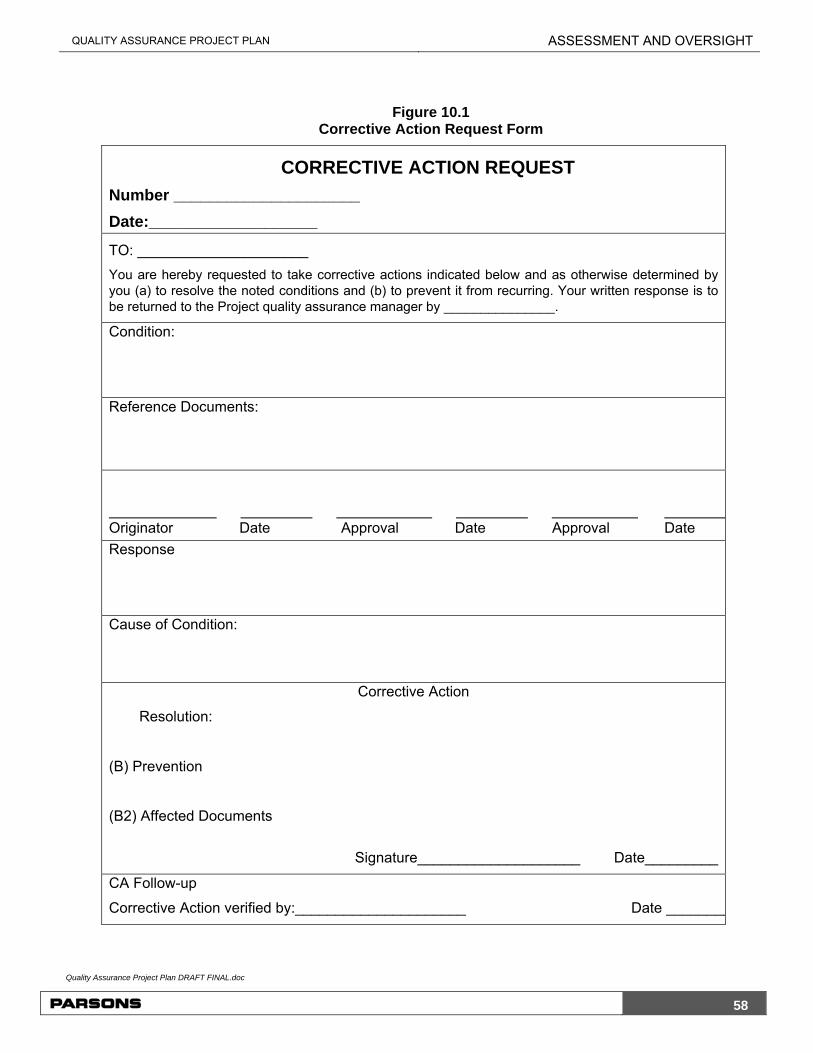
QUALITY ASSURANCE PROJECT PLAN ASSESSMENT AND OVERSIGHT
Quality Assurance Project Plan DRAFT FINAL.doc
58
Figure 10.1 Corrective Action Request Form
CORRECTIVE ACTION REQUEST
Number _____________________
Date:___________________
TO: _____________________
You are hereby requested to take corrective actions indicated below and as otherwise determined by you (a) to resolve the noted conditions and (b) to prevent it from recurring. Your written response is to be returned to the Project quality assurance manager by _______________.
Condition:
Reference Documents:
Originator Date Approval Date Approval Date
Response
Cause of Condition:
Corrective Action
Resolution:
(B) Prevention
(B2) Affected Documents
Signature____________________ Date_________
CA Follow-up
Corrective Action verified by:_____________________ Date ________

QUALITY ASSURANCE PROJECT PLAN REPORTS TO MANAGEMENT
Quality Assurance Project Plan DRAFT FINAL.doc
59
11.0 REPORTS TO MANAGEMENT Management personnel receive QA reports appropriate to their level of responsibility. The PM receives copies of all QA documentation. QC documentation is retained within the department that generated the product or service except where this documentation is a deliverable for a specific contract. QC documentation is also submitted to the project QAO for review and approval. Previous sections detailed the QA activities and the reports, which they generate. Among other QA audit reports that may be generated during the conduct of activities, a final audit report for this project will be prepared by the QAO. The report will include:
Periodic assessment of measurement data accuracy, precision, and completeness
Results of performance audits and/or system audits
Significant QA problems and recommended solutions for future projects, and
Status of solutions to any problems previously identified.
Additionally, any incidents requiring corrective action will be fully documented.

QUALITY ASSURANCE PROJECT PLAN REFERENCES
Quality Assurance Project Plan DRAFT FINAL.doc
60
12.0 REFERENCES Taylor, J. K., 1987. Quality Assurance of Chemical Measurements. Lewis Publishers,
Inc., Chelsea, Michigan.
USEPA, 1983. Methods for Chemical Analysis of Water and Wastes, EPA600/4-79/020, U.S. Environmental Protection Agency, Environmental Monitoring and Support Laboratory, Cincinnati, OH, Rev. March.
USEPA, 1986. NEIC Policies and Procedures. EPA 330/9-78-001-R. United States Environmental Protection Agency, Office of Enforcement and Compliance Monitoring, Washington, D.C. May 1978, revised May 1986.
USEPA, 1987. Data Quality Objectives for Remedial Response Actions Activities: Development Process. EPA/540/G-87/003, OSWER Directive 9355.0-7- U.S. Environmental Protection Agency, Washington, D.C.
USEPA, 1992. Methods for the Determination of Non-Conventional Pesticides in Municipal and Industrial Wastewater, EPA 821 RR-92-002, April.
USEPA, 1995. Methods for the Determination of Organic Compounds in Drinking Water, EPA-600/R-95/131, August.
USEPA, 2000. Guidance for the Data Quality Objective Process. EPA QA/G-4. Office of Environmental Information. August.
USEPA, 2001. EPA Requirements for Quality Assurance Project Plans. EPA QA/R-5. Office of the Environmental Information. March.
USEPA, 2002. Guidance for Quality Assurance Project Plans. EPA QA/G-5. U.S. Environmental Protection Agency. December.
USEPA, 2009. USEPA SW846 Test Methods for Evaluating Solid Waste, Physical and Chemical. 3rd edition including Final Update IV. U.S. Environmental Protection Agency, Washington, D.C. December.
USEPA, 2012a. ICP-AES Data Validation SOP HW-2a, Revision 15, USEPA Region 2, December.
USEPA, 2012b. ICP-MS Data Validation, SOP HW-2b, Revision 15. USEPA Region 2. December.
USEPA, 2012c. Mercury and Cyanide Data Validation SOP HW-2c, Revision 15. USEPA Region 2, December.
USEPA, 2013a. USEPA National Functional Guidelines for Superfund Organic Methods Data Review, EPA 540-R-14-002. U.S. Environmental Protection Agency, Washington, D.C. October.
USEPA, 2013b. USEPA National Functional Guidelines for Superfund Inorganic Methods Data Review, EPA 540-R-13-001. U.S. Environmental Protection Agency, Washington, D.C. October.

QUALITY ASSURANCE PROJECT PLAN REFERENCES
Quality Assurance Project Plan DRAFT FINAL.doc
61
USEPA, 2013c. Pesticide Data Validation, SOP HW-36, Revision 4. USEPA Region 2. May.
USEPA, 2013d. Polychlorinated Biphenyl (PCB) Aroclor Data Validation, SOP HW-37, Revision 3. USEPA Region 2, May.
USEPA, 2013e. Semivolatile Data Validation SOP HW-35, Revision 2. USEPA Region 2, March.
USEPA, 2013f. Low/Medium Volatile Data Validation, SOP HW-33, Revision 3. USEPA Region 2. March.
USEPA, 2013g. USEPA CLP National Functional Guidelines for Inorganic Superfund Data Review. EPA 540-R-013-001. U.S. Environmental Protection Agency, Washington, D.C. October.
USEPA, 2013h. USEPA CLP National Functional Guidelines for Superfund Organic Data Review, EPA-540-R-014-002. U.S. Environmental Protection Agency, Washington, D.C. October.

ATTACHMENT 1 STANDARD OPERATING PROCEDURES

PARSONS
QAPP Attachment A - SOPs.docx
A-2
STANDARD OPERATING PROCEDURE LOW-FLOW PURGING AND GROUNDWATER SAMPLING
1.0 PURPOSE OF PROCEDURE
This Standard Operating Procedure (SOP) describes the guidelines for low-flow purging and groundwater sampling as described in the Groundwater Sampling Plan or as otherwise specified.
2.0 GENERAL REQUIREMENTS AND CONSIDERATIONS
A. Personnel involved in well development procedures will follow the prescribed procedures in the Health and Safety Plan (HASP).
B. Well sampling will be documented to verify that proper procedures are followed. Documentation will be in accordance with the requirements specified Quality Assurance Project Plan (QAPP).
3.0 EQUIPMENT AND SUPPLIES
Electronic tablet, Field book and project plans Personal protective equipment in accordance with the HASP Water level indicator In-line multi-parameter water quality meter with flow-through cell (Horiba U-22, or
equivalent) Plastic or stainless steel beaker (or similar) Decontamination supplies Low flow (less than 0.1 – 0.5 L/min) pump (peristaltic) HDPE/Teflon tubing (dedicated) Coolers and ice Sample bottles, and Shipping supplies.
4.0 LOW-FLOW PURGING
A. Immediately prior to pumping each monitoring well, the static water level will be measured with a clean water level meter. Measurements will be recorded to the nearest 0.01 foot.
B. A peristaltic pump or equivalent with disposable tubing will be set up next to the sampling location on an elevated surface (table or cooler). In order to minimize interference and cross contamination, the dedicated tubing will be of high density polyethylene (HDPE), polytetrafluoroethylene (PTFE, e.g., Teflon®) or equivalent. These materials are relatively inert for sampling inorganic or organic analytes. Therefore, negative bias towards the proposed groundwater sample analyses for VOCs is not anticipated.
C. One end of dedicated tubing will be inserted into the well. The other end is attached to a short length of flexible (silicone) dedicated tubing, which will be threaded around the

PARSONS
QAPP Attachment A - SOPs.docx
A-3
rotor, out of the pump, and connected to a discharge tube. The liquid moves totally within the tubing, thus no part of the pump contacts the liquid.
D. During the initial low-flow sampling event, the pump will be started at its lowest speed setting and slowly increased until discharge occurs. After start-up, the water level will be checked, and the pump speed will be adjusted until there is little or no water level drawdown (less than 0.3 feet). During pump start-up, drawdown may exceed the 0.3 foot target and then recover as pump flow adjustments are made. If the minimal drawdown that can be achieved exceeds 0.3 feet, but remains stable, purging will continue until indicator parameters stabilize. During subsequent sampling events, the low-flow pumping rate established during the initial event will be used to purge each well. This rate will be adjusted as required to minimize drawdown.
E. The water level and pumping rate will be monitored and recorded every five to ten minutes during purging. The pumping rate will be adjusted to ensure minimal drawdown. Any pumping rate adjustments will also be recorded. Surging of water during pumping will be avoided. The pump intake will be kept submerged to avoid pump suction loss or air entrainment and to ensure that the sample tubing remains filled with water.
F. Purging will continue until indicator parameters stabilize.
H. If the well goes dry before field parameters have stabilized, the well will be allowed to recharge for up to 24 hours and then sampled and the sample conditions (including field parameters) will be noted on the field sampling form. Full documentation of the efforts made to achieve stabilization will be recorded in the field notebook.
I. All purge water will be transported to the Water Treatment Plant for disposal.
5.0 MONITORING OF INDICATOR PARAMETERS DURING PURGING
A. All groundwater quality monitoring equipment will be decontaminated in accordance with the Equipment Decontamination SOP.
B. All groundwater quality monitoring equipment will be calibrated daily, prior to use, per the manufacturer’s specifications.
C. Once an acceptable drawdown pumping rate is established and maintained, the designated field parameters will be monitored at 3-minute intervals using a flow-through cell. The required indicator parameters are pH, conductivity, temperature, and turbidity. The water level will also continue to be monitored and recorded, as well as any changes to the pumping rate.
D. Purging is considered complete and sampling may begin when the indicator parameters listed above have stabilized. Stabilization has occurred when three consecutive readings, taken at ten minute intervals, are within the following limits:
1) pH: +/- 0.5 standard pH unit
2) Conductivity: +/- 10%
3) Temperature: +/- 0.5o C
4) Turbidity: +/- 10% or < 10NTU or in a 10 NTU range for 30 min

PARSONS
QAPP Attachment A - SOPs.docx
A-4
E. Water quality parameter will be collected using in-line multi-parameter water quality meter with flow-through cell meter.
F. If sampling for total and filtered metals, a filtered and unfiltered sample will be collected. Samples may be filtered in the field using a 0.45-micron disposable filter. Alternatively, samples may be collected in to the appropriate laboratory container and filtered in the laboratory.
6.0 GROUNDWATER SAMPLING
A. Groundwater samples will be collected immediately after the indicator parameters have stabilized.
B. Comments regarding the color and any obvious odors associated with the water will be recorded in the field notebook or electronic device.
C. Samples will be collected using HDPE or Teflon-lined sample tubing. The sample tubing will be disconnected upstream (on the pump side) of the flow-through-cell prior to sample collection. Sample tubing will remain full during sampling.
D. Aeration of samples will be minimized.
E. Groundwater will be pumped slowly into the laboratory-supplied sample containers. VOA vials will be provided pre-preserved by the analytical laboratory. If natural effervescence is present in the samples, no preservative will be used for the VOC samples.
F. VOA vials will be filled and sealed in accordance with headspace requirements prescribed by the analytical laboratory and the analysis method. If degassing bubbles are evident in vials, fresh samples will be obtained. The pumping velocity will be reduced as needed. In addition, it may be necessary to collect VOC samples without preservation to minimize effervescing effects.
G. After sample collection, sample bottles will be labeled in accordance with current standards, and the appropriate chain of custody forms will be completed. The sample labels will be such: Well ID_YYYY-MM-DD
H. Samples will be placed in appropriate containers, preserved to 4 deg C, sealed, and transported expeditiously to the analytical laboratory. Between collection and shipment, samples will be kept in a secure storage room or under the samplers personnel control at all time. Sample packaging will follow laboratory guidelines and shipped via overnight shipping. All samples will be shipped to arrive at the laboratory within parameter specific holding times.
I. Sample container, preservation, and holding times are detailed in Section 4 of the QAPP. Sample storage, packaging, shipment, sample control, and custody procedures are detailed in Section 4 of the QAPP.

PARSONS
QAPP Attachment A - SOPs.docx
A-5
STANDARD OPERATING PROCEDURE SAMPLING EQUIPMENT DECONTAMINATION
1.0 PURPOSE OF PROCEDURE
This Standard Operating Procedure (SOP) describes the guidelines for the decontamination of sampling equipment.
2.0 GENERAL REQUIREMENTS
A. Procedures for decontamination of field personnel will be specifically addressed in the Health and Safety Plan (HASP).
B. Decontamination activities will be documented to verify that proper procedures are followed. Documentation will be in accordance with the requirements specified in the Work Plan.
3.0 SAMPLING EQUIPMENT DECONTAMINATION PROCEDURES
A. All sampling equipment that may contribute to the contamination of a sample will be thoroughly decontaminated before its initial use, unless specific documentation exists that the sampling equipment has been decontaminated.
B. Generally, sampling equipment can be cleaned by hand. Delicate equipment, such as the submersible pump, will be cleaned by hand. The following procedure is given as a typical sequence that will be modified based on site conditions.
C. Other sampling equipment that can be cleaned by hand will be decontaminated as follows:
1) Wash and scrub with detergent (non-ionic)
2) Tap water rinse
3) DI water rinse
4) Isopropanol rinse, and
5) Air dry.
D. Steel tapes, water probes, transducers, thermometers, and water quality meters will be rinsed in distilled water or cleaned in a detergent solution and rinsed in DI water after each use.
E. Pumps will be cleaned in water/detergent solution, followed by a tap water rinse, and flushed with DI water after each use.
F. Use of high-pressure steam or hot water washing may be substituted for hand scrubbing if it effectively removes contaminants and soil and can be done safely without burning or contaminating the personnel. Special racks will be used to hold equipment during high-pressure washing. High-pressure washing will not be conducted on delicate equipment.
G. More “complicated” samplers require more “complicated” decontamination procedures. The use of piston and other samplers with numerous internal parts should be avoided. If

PARSONS
QAPP Attachment A - SOPs.docx
A-6
bladder pumps need to be used the decontamination sequence will be the same. The pump will be broken down to individual pieces and the bladder itself replaced.
H. To the extent possible, sample tubing shall be either dedicated to a particular well/location or disposed after each use. Tubing that cannot be dedicated to a particular well/location will be disposed of and not used for any other purpose.
I. Sampling and downhole equipment that has come into contact with non-aqueous phase liquids (NAPLs) or high concentration dissolved-phase contaminants (10 ppm range VOCs) will also undergo a rinse with isopropanol to ensure removal of organics. The decontamination steps for high concentration organics are:
1) Wash and scrub with detergent (non-ionic)
2) Tap water rinse
3) Isopropanol rinse
4) DI water rinse, and
5) Air dry.

PARSONS
QAPP Attachment A - SOPs.docx
A-7
STANDARD OPERATING PROCEDURE SEDIMENT SAMPLING
1.0 PURPOSE OF PROCEDURE
This Standard Operating Procedure (SOP) describes the guidelines for the collection of sediment samples.
2.0 GENERAL REQUIREMENTS
A. Procedures for surface soil sampling will be specifically addressed in the Health and Safety Plan (HASP).
B. Sediment sampling will be documented to verify that proper procedures are followed. Documentation will be in accordance with the requirements specified in the Quality Assurance Project Plan (QAPP).
3.0 EQUIPMENT AND SUPPLIES
Field book and project plans Personal protective equipment in accordance with the HASP Stainless steel hand tools (trowel, spoon, hand auger) Stainless steel bowl Decon supplies Sample bottles Coolers and ice, and Shipping supplies.
4.0 SAMPLING AND LOGGING PROCEEDURES
4.1 Decontamination of Tools
A. The sampling tools will be decontaminated (as described in the Sampling Equipment Decontamination SOP) prior to the first and between each sample.
4.2 Sample Collection
A. Sediment samples may be collected as either a grab sample or as a composited sample. The sample type will be identified in the work plan. Additionally, depending on the parameter being sampled, the use of an En Core® or Terra Core® sample kit may be required. Sample collection details are provided below.
B. Grab samples will be collected directly from the sediment surface into the appropriate sample container. The sampling location will be identified based on the requirements of the sampling program in the Project Work Plan. Samples will be collected using a stainless steel trowel or spoon which has been decontaminated in accordance with the Equipment Decontamination SOP.
C. Composited samples will be collected directly from the sediment surface into a clean, stainless steel bowl. The sample collection locations will be identified based on the requirements of the sampling program in the Project Work Plan. Samples will be

PARSONS
QAPP Attachment A - SOPs.docx
A-8
collected using a stainless steel trowel or spoon which has been decontaminated in accordance with the Equipment Decontamination SOP. Once the samples have been collected into the bowl, the sediments will be thoroughly mixed then placed in to the appropriate sampling containers based on the analytical parameter list.
D. For VOC analyses, one small Ziploc® bag and two sample containers will be filled with soil for field headspace analysis and off-site laboratory analysis. For all other analyses (SVOCs, Metals, Pesticides, and PCBs), samples will be placed in jars as prepared and provided by the laboratory.
E. To collect an En Core® sample, insert the En Core® sampler into the soil to be sampled, being sure that the top of the plunger on the sampler is in the locked position (parallel to the handle of the sampler). Make sure that the En Core® sampler is completely filled with the sample (weight of sample should be five grams), level off the bottom of the sampler to remove any excess sample material. Cap coring body and remove the capped sampler by depressing locking lever. Attach the label on the coring body and return full En Core® sampler to the zipper bag. Seal the bag and put on ice.
F. To collect a Terra Core® sample:
Step 1 - Have ready a 40ml glass VOA vial containing the appropriate preservative. With the plunger seated in the handle, push the Terra Core® into freshly exposed soil until the sample chamber is filled. A filled chamber will deliver approximately five or 10 grams of soil.
Step 2 - Wipe all soil or debris from the outside of the Terra Core® sampler. The soil plug should be flush with the mouth of the sampler. Remove any excess soil that extends beyond the mouth of the sampler.
Step 3 - Rotate the plunger that was seated in the handle top 90° until it is aligned with the slots in the body. Place the mouth of the sampler into the 40ml VOA vial containing the appropriate preservative, and extrude the sample by pushing the plunger down. Quickly place the lid back on the 40ml VOA vial. Note: When capping the 40ml VOA vial, be sure to remove any soil or debris from the top and/or threads of the vial.
G. The samples submitted for laboratory analysis will be handled according to Section 4 of the QAPP under chain-of-custody procedures.
H. For field duplicates, and matrix spike/matrix spike duplicate samples, sufficient extra volume must be collected for the laboratory to perform these quality control analyses.
I. Jars, as prepared and provided by the laboratory will be filled with samples and placed in a cooler on ice for possible laboratory analysis.
5.0 DOCUMENTATION
A. Documentation of sediment samples in the field logbook will be the responsibility of the supervising geologist/hydrogeologist.
B. The following minimum information will be recorded during and upon completion of sampling.

PARSONS
QAPP Attachment A - SOPs.docx
A-9
Project name and number Sample location identification Date of soil sample and time completed Depth to and length of sampling interval, and Name of supervising geologist/hydrogeologist.

PARSONS
QAPP Attachment A - SOPs.docx
A-10
STANDARD OPERATING PROCEDURE SURFACE SOIL SAMPLING
1.0 PURPOSE OF PROCEDURE
This Standard Operating Procedure (SOP) describes the guidelines for the collection of soils from within approximately five-feet of the ground surface. This will include those samples collected for waste characterization of soils for disposal.
2.0 GENERAL REQUIREMENTS
A. Procedures for surface soil sampling will be specifically addressed in the Health and Safety Plan (HASP).
B. Surface Soil sampling will be documented to verify that proper procedures are followed. Documentation will be in accordance with the requirements specified in the Quality Assurance Project Plan (QAPP).
3.0 EQUIPMENT AND SUPPLIES
Field book and project plans Personal protective equipment in accordance with the HASP Marker stakes, flagging, and paint Stainless steel hand tools (trowel, spoon, hand auger) Stainless steel bowl Soil sample containers Decon supplies Sample bottles Coolers and ice, and Shipping supplies.
4.0 SAMPLING AND LOGGING PROCEEDURES
4.1 Decontamination of Tools
A. The sampling tools will be decontaminated (as described in the Sampling Equipment Decontamination SOP) prior to the first and between each sample.
4.2 Sample Collection
A. Soil samples may be collected as either a grab sample or as a composited sample. The sample type will be identified in the work plan. Additionally, depending on the parameter being sampled, the use of an En Core® or Terra Core® sample kit may be required. Sample collection details are provided below.
B. Grab samples will be collected directly from the ground surface into the appropriate sample container. The sampling location will be identified based on the requirements of the sampling program in the Project Work Plan. Samples will be collected using a stainless steel trowel or spoon which has been decontaminated in accordance with the Equipment Decontamination SOP.

PARSONS
QAPP Attachment A - SOPs.docx
A-11
C. Composited samples will be collected directly from the ground surface into a clean, stainless steel bowl. The sample collection locations will be identified based on the requirements of the sampling program in the Project Work Plan. Samples will be collected using a stainless steel trowel or spoon which has been decontaminated in accordance with the Equipment Decontamination SOP. Once the samples have been collected into the bowl, the soil will be thoroughly mixed, then placed in to the appropriate sampling containers based on the analytical parameter list.
D. For VOC analyses, one small Ziploc® bag and two sample containers will be filled with soil for field headspace analysis and off-site laboratory analysis. For all other analyses (SVOCs, Metals, Pesticides, and PCBs), samples will be placed in jars as prepared and provided by the laboratory.
E. To collect an En Core® sample, insert the En Core® sampler into the soil to be sampled, being sure that the top of the plunger on the sampler is in the locked position (parallel to the handle of the sampler). Make sure that the En Core® sampler is completely filled with the sample (weight of sample should be 5 grams), level off the bottom of the sampler to remove any excess sample material. Cap coring body and remove the capped sampler by depressing locking lever. Attach the label on the coring body and return full En Core® sampler to the zipper bag. Seal the bag and put on ice.
F. To collect a Terra Core® sample:
Step 1 - Have ready a 40ml glass VOA vial containing the appropriate preservative. With the plunger seated in the handle, push the Terra Core® into freshly exposed soil until the sample chamber is filled. A filled chamber will deliver approximately five or 10 grams of soil.
Step 2 - Wipe all soil or debris from the outside of the Terra Core® sampler. The soil plug should be flush with the mouth of the sampler. Remove any excess soil that extends beyond the mouth of the sampler.
Step 3 - Rotate the plunger that was seated in the handle top 90° until it is aligned with the slots in the body. Place the mouth of the sampler into the 40ml VOA vial containing the appropriate preservative, and extrude the sample by pushing the plunger down. Quickly place the lid back on the 40ml VOA vial. Note: When capping the 40ml VOA vial, be sure to remove any soil or debris from the top and/or threads of the vial.
G. The samples submitted for laboratory analysis will be handled according to Section 4 of the QAPP under chain-of-custody procedures.
H. For field duplicates, and matrix spike/matrix spike duplicate samples, sufficient extra volume must be collected for the laboratory to perform these quality control analyses.
I. Jars, as prepared and provided by the laboratory will be filled with soil and placed in a cooler on ice for possible laboratory analysis.
5.0 DOCUMENTATION
A. Documentation of soil samples in the field logbook will be the responsibility of the supervising geologist/hydrogeologist.

PARSONS
QAPP Attachment A - SOPs.docx
A-12
B. The following minimum information will be recorded during and upon completion of soil sampling.
Project name and number Soil sample location identification Date of soil sample and time completed Generalized subsurface stratigraphy Depth to and length of sampling interval, and Name of supervising geologist/hydrogeologist.

PARSONS
QAPP Attachment A - SOPs.docx
A-13
STANDARD OPERATING PROCEDURE SURFACE WATER SAMPLING
1.0 PURPOSE OF PROCEDURE
This Standard Operating Procedure (SOP) describes the guidelines for surface water sampling as described in the Work Plan or as otherwise specified.
2.0 GENERAL REQUIREMENTS AND CONSIDERATIONS
A. Personnel involved in well development procedures will follow the prescribed procedures in the Health and Safety Plan (HASP).
B. Surface water sampling will be documented to verify that proper procedures are followed. Documentation will be in accordance with the requirements specified in the Quality Assurance Project Plan (QAPP).
3.0 EQUIPMENT AND SUPPLIES
Field book and project plans Personal protective equipment in accordance with the HASP Survey stakes, flags Peristaltic pump Meters, probes and standards for in-situ measurements Sample bottles, and Shipping supplies.
4.0 DIRECT DIPPING METHOD
A. The surface water sampling location will be identified in the field based on the mapping information included in the related work plan. The location of the sampling station should be identified and marked for future reference.
B. At each location, the following water quality parameters may be measured in the field: pH, conductivity, temperature, and turbidity. The requirement for the measurement of these parameters will be identified in the Project Work Plan.
D. Water quality measurements will be made using a flow through cell meter (Horiba U-52, YSI 6-Series, or equivalent). Calibration of the meter will be completed prior to use following the instrument manufacturer calibration protocols. Measurements should be obtained in-situ when possible; otherwise measurements can be obtained by immersing the instrument probes in a container filled with water from each sampling location. The container used for field measurements will be decontaminated between sampling locations by rinsing the container three times with water obtained at the new sampling location prior to collecting the field measurements.
E. Samples will be obtained from the proposed sampling locations by direct grab. The sample bottle shall be inverted, and lowered to one-half the water depth, and held at about a 45° angle with the mouth of the bottle facing upstream. If the sample is

PARSONS
QAPP Attachment A - SOPs.docx
A-14
unreachable, then use a telescoping pole with a clean poly dipper cup (laboratory supplied), and the water will be transferred to the appropriate container.
F. If the sampling location is unreachable with the pole and cup method, personnel may wade out into the water to collect the sample provided they have assessed the activity and are able to mitigate all hazards associated with this task. In this case, the waders will also be decontaminated between sample locations.
G. Sampling personnel shall not collect turbid or sediment-containing water, which could bias the sample results. If a laboratory supplied sample container contains a preservative added at the laboratory, then the sample will be collected from the pond using a new, clean glass container to collect the sample and transfer it into the pre-preserved laboratory container.
H. Sampling containers and appropriate preservatives are based on the analyses to be performed on each sample. Appropriate sample containers will be used for the analyses to be performed on each sample collected during this task.
J. When sampling for total and filtered metals, a filtered and unfiltered sample will be collected. Filtered samples may be obtained using a 0.45-micron disposable filter.
K. After collection, samples will be labeled following current conventions, and the appropriate chain-of-custody forms will be completed. Sample labels shall be as follows: LOCATION ID _YYYY-MM-DD.
L. Samples will be placed in appropriate containers (e.g., ice-filled coolers), preserved to a minimum of 4OC, sealed (to maintain the proper COC), and transported expeditiously to the analytical laboratory.
M. Sample container, preservation, and holding times are detailed in Section 4 of the QAPP. Sample storage, packaging, shipment, sample control and custody procedures are detailed in Section 4 of the QAPP.
4.1 Peristaltic Pump Samplers Method
A. Another device that can be effectively used to sample surface water is the peristaltic pump system. The use of a metal/PVC conduit to which the tubing is attached, allows for the collection of a surface water sample. Tubing will be changed between sampling locations to prevent cross contamination.
B. Peristaltic pumps vary in size and capability, with some being designed specifically for the simultaneous collection of multiple water samples.
C. At each location, the following water quality parameters will be measured in the field: pH, conductivity, temperature, and turbidity. Water quality parameter will be collected using in-line multi-parameter water quality meter with flow-through cell meter. Note that samples should not be collected after passing through the water quality meter but directly after the peristaltic pump.
D. When sampling for total and filtered metals, a filtered and unfiltered sample will be collected. Filtered samples may be obtained using a 0.45-micron disposable filter.

PARSONS
QAPP Attachment A - SOPs.docx
A-15
E. After sample collection, sample bottles will be labeled, and the appropriate chain-of-custody forms will be completed.
F. Samples will be placed in appropriate containers (e.g., ice-filled coolers), preserved to a minimum of 4OC, sealed (to maintain the proper COC), and transported expeditiously to the analytical laboratory.
G. Sample container, preservation, and holding times are detailed in Section 4 of the QAPP. Sample storage, packaging, shipment, sample control, and custody procedures are detailed in Section 4 of the QAPP.
5.0 DOCUMENTATION
A. All aspects of the surface water sampling will be recorded in a project field book. The following water quality parameters will be measured in the field: pH and temperature, conductivity, and turbidity. In addition, sample location, site conditions, weather, any deviations from this SOP and any other pertinent information will be recorded.