quality control manual - water resources - government of rajasthan
TRANSCRIPT

GOVERNMENT OF RAJASTHAN
WATER RESOURCES DEPARTMENT
QUALITY CONTROL MANUAL
March – 2011
Chief Engineer
Water Resources Department
Rajasthan, Jaipur


PREFACE
Status of water in Rajasthan is critical and complex. Ground water table is depleting
at fast rate across the state due to over exploitation. The availability of water is also
decreasing regularly due to abnormal growth of population. After independence,
major concentration was extended to water sector and 90% of state's water is utilized
by irrigated agriculture. But the major concerns in water sector are sustainability,
productivity, water management, pricing etc.
It will be our endeavor that the works are executed with strict quality standards
confirming to technical specifications with deployment of good construction
modalities. To achieve the objectives of an effective Quality Control Monitoring and
Quality Assurance Management System, an independent quality control unit has
been established and made operational. The important aspect is to develop quality
concept and capacity of field engineers to be continuously vigilant on quality
control. Accordingly a manual to promote procedure and guidelines of quality
control systems on the works of Water Resources Department has been prepared,
after detailed discussions and feedback experience from the prevailing practices.
The manual shall provide in depth understanding of the need of quality control,
including prescribing the tests required to be conducted for the materials during
construction and placement activities along-with post construction scenario. The
manual is designed to introduce various formats to be followed at various stages or
construction to achieve proper quality control and to transmit necessary reports. It
also provides an opportunity for the engineering personnel for deployment of their
skills in quality control procedures to increase useful life of structures being
constructed in confirmation with the international standards.
Although every care has been taken to check mistakes and misprints, yet it is
difficult to claim perfection. Any errors, omissions and suggestions for the
improvement and corrections in the Quality Control Manual are most welcome from
all the quarters, which may please be sent to the undersigned.

Quality Control Manual for Water Resources Department has been made under
valuable guidance and support of the Committee officers Sh.P.L.Solanki, Chief
Engineer Quality Control & Vigilance, Jaipur and Sh.G.R.Bhansali, Chief Engineer
SWRPD, Jaipur .Their valuable support for the finalization of Quality Control
Manual applicable to the construction works of Water Resources Department by
Sh. Narendra Mertia SE & TA and his team is thankfully acknowledged.
Date: 17th March, 2011 (Kundan Lal)
Place: JAIPUR Chief Engineer
Water Resources Department
Rajasthan, Jaipur

INDEX
CHAPTER NO. PARTICULARS PAGE
NO.
LIST OF INDIAN STANDARDS (i)-(iii)
CHAPTER-I QUALITY ASSURANCE AND CONTROL 1
CHAPTER-II ORGANISATIONAL SET-UP 5
CHAPTER-III GENERAL FUNCTIONS OF LABORATORIES 8
CHAPTER-IV DUTIES OF STAFF INCHARGE OF
LABORATORIES
16
CHAPTER-V DUTIES OF FIELD STAFF IN RELATION TO
QUALITY OF WORKS
20
CHAPTER-VI CO-ORDINATIONS 24
CHAPTER-VII QUALITY ASSURANCE 27
CHAPTER-VIII O.K. CARDS 29
CHAPTER-IX TESTS TO BE PERFORMED ON MATERIALS 39
CHAPTER-X LIST OF EQUIPMENT FOR CEMENT AND
CONCRETE TESTING
41
CHAPTER-XI FORMATS OF TEST RESULTS 43
CHAPTER-XII IMPORTANT SPECIFICATIONS 58
CHAPTER-XIII FREQUENCY OF TESTING 96
CHAPTER-XIV MONITORING THROUGH CONTROL CHARTS 102
CHAPTER-XV
COMPILATION OF QUALITY CONTROL DATA 107
CHAPTER-XVI PROCEDURE FOR EXECUTING EARTH WORK 108
CHAPTER-XVII PROCEDURE FOR EXECUTING CONCRETE
LINING
112
CHAPTER-XVIII PROCEDURE FOR EXECUTING RCC WORK &
CONCRETE FOR STRUCTURES
117
CHAPTER-XIX PROCEDURE FOR SHOT-CRETING AND
GUNITING
122
CHAPTER-XX DETERMINATION OF FIELD MOISTURE & DRY
DENSITY OF COMPACTED EARTH FILL
129
CHAPTER-XXI DETERMINATION OF FIELD DENSITY BY
SAND REPLACEMENT METHOD
130
CHAPTER-XXII CHECK LIST FOR QUALITY CONTROL UNIT
132
ANNEXURE-I SKETCH SHOWING THE ROLES AND
RESPONSIBILITY MATRIX
139
ANNEXURE-II ORGANISATIONAL CHART 142
ANNEXURE-III SKETCH SHOWING CONSTRUCTION – JOINT
IN LINING
143

ANNEXURE-IV INSPECTION OF TESTING ACTIVITIES 144
ANNEXURE-V-A SKETCH SHOWING AIR – WATER GUN 145
ANNEXURE-V-B AIR – MORTAR GUN 146
ANNEXURE-VI ILLUSTRATIVE SKETCH SHOWING
TREATMENT OF CANAL PRISM IN EXPANSIVE
SOILS WITH CNS MATERIALS
147
ANNEXURE-VII TYPICAL CROSSECTION OF A DISTRIBUTARY
WITH C.N.S. SUB GRADE
148
ANNEXURE-VIII CURVE SHOWING RELATION BETWEEN
SPECIMEN SIZE AND STRENGTH OF
CONCRETE CORE
149
ANNEXURE-IX DATA OF THE CORES TAKEN FROM IN SITU
CONCRETE CANAL LINING
150
ANNEXURE-X ILLUSTRATION OF PREPARATION OF
CONTROL CHARTS FOR CEMENT AND
CONCRETE
151
ANNEXURE-XI GRAPH SHOWING CORRECTION FACTOR FOR
HEIGHT/ DIAMETER RATIO OF A CORE
161
ANNEXURE-XII STATEMENT SHOWING CAPACITY OF PAVER
AND MECHANICAL TRIMMER
162
ANNEXURE-XIII GOVERNMENT OF RAJASTHAN ,IRRIGATION
DEPPARTMENT ORDER OF DATED 4-11-96
163
ANNEXURE-XIV GOVERNMENT OF RAJASTHAN ,WRD ORDER
OF DATED 27-9-10
165
ANNEXURE-XV PHOTOGRAPHS OF KEY/CRITICAL
EQUIPMENTS
168

LIST OF INDIAN STANDARDS
S.
No. Short Title
IS. to various
Standards
(A) Cement
1 Specification for 33 grade ordinary Portland cement IS:269 -1989
2 Specification for Rapid-hardening Portland cement IS:8041 -1990
3 Specification for Portland pozzolona cement IS:1489 (Part 1&2)
1991
4 Methods of physical test for hydraulic cement IS:4031 -1988
5 Method of chemical analysis of hydraulic cement IS:4032 -1985
6 Method of sampling for hydraulic cement IS:3535 -1986
7 Standard sand for testing of cement IS:650 -1991
8 Specification for 43 grade ordinary Portland cement IS:8112 -1989
9 Specification for 53 grade ordinary Portland cement IS:12269-1987
(B) Coarse / Fine Aggregate
1 Specification for coarse & fine aggregates IS:383-1970
2 Methods of test for aggregates for concrete
particle size and shape.
IS:2386 (Part I)-1963
3 Methods of test for aggregates for concrete
estimation of deleterious materials and organic
impurities.
IS:2386 (Part II)-1963
4 Methods of test for aggregates for concrete specific
gravity, density, voids, absorption & bulking.
IS:2386 (Part III)- 1963
5 Methods of test for aggregates for concrete
Mechanical properties.
IS:2386 (Part IV)-1963
6 Methods of test for aggregate for concrete
Soundness.
IS:2386 (Part V)- 1963
7 Methods of test for aggregate for concrete
measuring mortar making properties of fine
aggregates.
IS:2386 (Part VI)-1963
8 Methods of test for aggregates for concrete
alkali aggregate reactivity.
IS:2386 (Part VII)-
1963
9 Methods of test for aggregates for concrete
petrographic examination.
IS:2386 (Part VIII)-
1963
(C) Bricks
1 Method for sampling of clay building bricks IS:5454 -1978
2 Method of tests of burnt-clay building bricks IS:3495 (Parts 1 to 4)-
1992
3 Common burnt clay building bricks IS:1077 -1992

S.
No. Short Title
IS. to various
Standards
(D) Masonry Mortar
1 Specification for sand for masonry mortars IS:2116 -1980
2 Code of practice for preparation and use of
masonry mortar.
IS:2250 -1981
(E) Cement Concrete
1. Specification for coarse and fine aggregate IS:383 - 1970
2 Specification for compressive strength, flexural
strength.
IS:516 -1959
3 Code of practice for plain & reinforced concrete IS:456 -2000
4 Methods of sampling and analysis of concrete IS:1199 - 1959
5 Recommended guide lines for concrete mix design IS:10262 - 1982
(F) Curing Compound
1 Standard test method for water retention & day
light reflection test on concrete.
ASTM-C-156809
2 Standard method of test for effect of organic
materials in fine aggregate on strength of mortar.
ASTM-C-87-69
3 Standard specification for liquid membranes
forming compounds.
ASTM- C-309-89
(G) PVC Water Stops
1 Code of practice for provision of water stops IS:12200 - 1987
2 Procedure for Testing Parts of IS:8543
3 Standard Test methods for Tensile properties of
Plastics.
ASTM : D 638-1991
4 Standard Test methods for Thermoplastic
Elastomers Tension.
ASTM : D 412-1992
(H) HYSD BARS
1 Specifications for HYSD bars. IS:1786 - 1985
2 Specification for Mild Steel and Medium Tensile
steel bars for concrete reinforcement.
IS:432 (Part I) -1982
3 Method for Tensile testing of steel wires IS:1521 - 1972
4 Hard drawn steel wire for concrete reinforcement IS:432 (Part II) -1982
5 Method for Tensile testing of Steel IS:1608 - 1995
6 Code of practice for bending & fixing of bars for
concrete reinforcement.
IS:2502 - 1963
(I) Precast R.C.C. Pipes
1 Specifications for precast concrete pipes IS:458 - 1988
2 Methods of test for concrete pipes IS:3597 – 1985

S.
No. Short Title
IS. to various
Standards
1 Preparation of dry soil samples IS:2720 (Part I) -1983
2 Determination of water content (moisture content) IS:2720 (Part II) -1973
3 Determination of specific gravity of fine grained
soils.
IS:2720 (Part III) -1980
Sect/1
4 Determination of specific gravity of fine, medium
& coarse grained soils.
IS:2720 (Part III) -1980
Sect/2
5 Grain size analysis IS:2720 (Part IV) -1985
6 Determination of liquid and plastic limit IS:2720 (Part V)- 1985
7 Determination of shrinkage factors IS: 2720 (Part VI)- 1972
8 Determination of water content -dry density
relation using light compaction.
IS:2720 (Part VII) -1980
9 Determination of water content -dry density
relation using heavy compaction.
IS:2720 (Part VIII) -
1983
10 Determination of water content -dry density
relation using constant weight of soil method.
IS:2720 (Part IX) -1971
11 Determination of unconfined compressive strength IS:2720 (Part X) -1973
12 Determination of shear strength parameters
(tri-axial) without measurement of pore water
pressure (tri-axial compaction).
IS:2720 (Part XI) -1971
13 Determination of shear strength parameters with
measurement of pore water pressure.
IS:2720 (Part XII)- 1981
14 Direct shear test IS:2720 (Part XIII) -
1986
15 Determination of density index (relative density)
of cohesionless soils.
IS:2720 (Part XIV)-
1983
16 Determination of consolidation properties IS:2720 (Part XV) -1986
17 Determination of permeability IS:2720 (Part 17)- 1986
18 Determination of dry density of soils, in- place by
the sand replacement method.
IS:2720 (Part 28)- 1974
19 Determination of dry density of soils, in- place by
core-cutter method.
IS:2720 (Part 29)- 1975
20 Laboratory vane shear test. 1S:2720 (Part 30) -1980
21 Determination of the density in place by the ring
and water replacement method.
IS:2720 (Part 33)- 1971
22 Determination of free swell index of soils IS: 2720 (Part 40)- 1977
23 Measurement of swelling pressure of soils IS: 2720 (Part 41)- 1977
24 Classification and identification of soils for
general engineering purposes.
IS:1498-1970


1
CHAPTER – I
QUALITY ASSURANCE AND CONTROL
1. INTRODUCTION
Evaluation of water resources projects involves enormous expenditure. They are
time bound programme and require assistance from various technical bodies for
investigation, design, planning and execution. To have a safe durable structure, it is
necessary that the materials and standard of execution fully satisfy the
specifications. It is to be recognized that the ultimate efficiency of the performance
of a project will depend upon proper layout and designs, the ultimate health of the
project during life scale of its operational phase will depend largely on the quality
achieved during its construction.
Each and every job whether big or howsoever small shall require to be executed to
acceptable construction quality duly confirming to sound design principles,
specifications and deployment of good methodology or modern technique and
procedures. To achieve the requisite objectives, it is essential to introduce a result
oriented quality management system.
This system is planned to orient the whole range of quality effort on a continuous
basis covering quality assurance and quality control, broadly out lined below
including steps initiated for its meticulous implementation.
1.1 Orientation and training of construction supervision/quality control
staff
A capable and functional construction supervision (CS) and quality control / quality
assurance team is needed to ensure implementation of contract specifications. To
achieve this objective intensive training will be given to all related staff of
construction / quality control in suitable batches covering specifications for the
works to be executed and also the procedure to conduct various tests in the field and
laboratories. Recommendation of I.S. codes will be explained in the training so as to
cover key construction and QC / QA aspects.

2
1.2 Laboratory system for testing of Input and Outputs
Looking to the overall quantum of work and the scattered area in different
zones, establishment of laboratories at different levels and places forms an
important link of project organisation for quality control. The system is
required to provide reliable and accurate testing support to fulfill the
objectives. Accuracy and reliability in testing will depend upon the
competence of testing personal, accuracy of apparatus, quality of reagents
used, and maintenance of requisite environmental conditions. Introduction of
"Mobile testing laboratory system" will prove to be highly result-oriented.
This can be supplemented by adequate nos. of site labs, field laboratories and
zonal laboratories.
1.3 O.K. Card System
It provides a systematic approach towards assuring quality construction and
has proved to be practical mechanism for enforcement of technical
specifications. For the purpose, each work is divided in various activities in
proper sequence/order of construction and listed in chronological order of
occurrence in O.K. Card. The cards are maintained in 2 colors (Pink and
Green) to be operated by construction and quality control units separately.
During execution of work both cards are operated simultaneously and will be
kept on record by Executive Engineer concerned.
2. OBJECTIVES AND SCOPE OF QUALITY CONTROL
The objective of quality control management is to collect, process and then
communicate the data related to the quality of inputs and outputs as well as
finished item of work to those who are responsible for the quality. Any
programme of quality control seeks to ensure adequacy and uniformity of
quality through the following operations.
1. To ensure that the works are being executed in conformity with the
prescribed specification.

3
2. Inspection of storage, handling and processing facilities for all materials
in conformity with accepted or specified practice.
3. Monitoring the variation in specification of the materials and quantities
used in the operation of production and in the final product by suitable
observation, measurements or tests.
4. In order to achieve the common goal – Construction quality in the
execution of project, the roles and responsibility matrix, as depicted in
Annexure-I shall be broadly followed by :
1. GOR 2. Contractor 3. Project Construction Team
4. Project QC/QA Team and 5. Project Design Team
5. Analysis of the observed variations by statistical or other techniques.
6. Feed-back of the results of analysis for exercise of control at each stage
and to take corrective steps for maintaining the variations within
specified limits.
7. Indicating expeditiously the possible remedial measures, wherever
warranted to ensure execution of works as per drawings / specifications.
8. Rejecting, where warranted, the material or the product at any
intermediate or final stage in case acceptance criteria is not satisfied. The
rejected material should be removed from work site immediately.
3. QUALITY CONTROL MANUAL
It is very important constituent of the quality management system. It is a
document encompassing specific requirement, which if fulfilled, shall help in
effectively implementing the quality control system to achieve the objective
of good construction quality. It covers broadly, the objectives, functions and
operations of the Q.C. organisation; duties and responsibilities of Q.C.
personnel; Q.C. Laboratory System; O.K. Cards; Monitoring through Control
Charts; Control on workmanship; Tests on materials; Important
specifications; Standards to be adopted for materials and works; Frequency
of testing and reporting; Compilation of Q.C. Data and Statistical Analysis
etc.; Documentation and Feed-back; Inspection etc.

4
4. CONFIGURATION OF QUALITY MANAGEMENT SYSTEM
QUALITY MANAGEMENT SYSTEM
Quality planning,
Q.C. Manual;
Training of Q.C./Q.A.
Staff, Infrastructure
etc.
Quality Control Quality Assurance
5.1 QUALITY CONTROL: (Q.C.)
The operational techniques and activities that are used to fulfill the
requirements for quality.
5.2 QUALITY ASSURANCE: (Q.A.)
All the planned and systematic activities implemented within the quality
system and demonstrated as needed to provide adequate confidence that an
entity will fulfill requirements for quality; and making sure that the quality of
a product is what it should be. Purpose of Quality Assurance is to prevent
problems before they occur, to identify and correct them swiftly if they occur
and to uncover the root cause.
5.3 QUALITY MANAGEMENT
All activities of the overall management function that determine the quality
policy, objectives and responsibilities, and implement them by means such as
Quality Planning, Quality Control, Quality Assurance, and Quality
Improvement within the quality system.
The QUALITY CONTROL MANUAL being adopted for Water Resources
Department (the salient requirements of which are being outline in the
various chapters) aims at a “System Approach” to ensure that upon
implementation , the quality levels as set and defined in the specifications
and contract documents and relevant Indian Standards would be met in the
execution of project works.

5
CHAPTER – II
ORGANISATIONAL SET-UP
GENERAL
I. Anyone connected with quality control work, should possess adequate
knowledge and experience of quality control works and be well conversant
with testing of construction materials. The object of quality control should be
clearly understood by them in letter and spirit so as to help in construction
and achieve high order of quality as laid down in specifications for works by
controlling various factors responsible for deterioration in quality,
investigating reasons therefore and suggesting ways and means for
improvement.
II. To have proper and independent quality, quality control formation shall
consist of an independent unit headed by Chief Engineer Quality Control.
The C.E. shall have three S.E.'s in-charge of Quality Control Circle for the
various construction activities of different zones and the S.E.'s shall have a
team of E.E.'s to look after the work of different circles. Thus there will be
separate streams of construction and quality control assurance respectively
up to the level of C.E. (Organisational Chart attached at Annexure-II).
III. Every Q/C Circle shall be divided in number of division and each division
shall be headed by the Executive Engineer for the purpose of effective
quality control, every divisional jurisdiction shall be sub-divided in number
of units and each unit is to be put under the charge of A.En. The E.E. quality
control shall make all arrangements for the demarcating the areas of
operation of every quality control staff and issue a duty chart for each
member after approval from the C.E / S.E. Field Laboratory will be situated
at important nodal points which shall cover all the adjoining works and in-
charge will be T.A. to Executive Engineer. Site Laboratories as per
requirement in field shall be maintained by concerned site in-charge
(construction) and also utilized by Assistant Engineer Q/C for carrying out
necessary tests whenever site is inspected by him.

6
IV. One of the fundamental principles to be understood and kept in mind is that
the overall responsibility for achieving construction quality in each sub-
project – rests with the execution unit and construction staff shall be fully
responsible for quality of work. Requisite assistance is to be provided by the
Q.C. Staff for ensuring construction quality.
Functions of Quality Control Units
The main function of Q.C. units is to have independent checking and control
of works. Since the works in the zones are of scattered nature, the quality
control units can not exercise concurrent quality control, but it has been
planned that these units should act in such a manner that necessary quality
control requirements are fulfilled jointly with the execution staff. It will be
the responsibility of quality control staff to ensure that all-requisite test as
per IS / relevant standards and specifications are carried out in site / field /
zonal or central laboratories. The quality control units will carry out periodic
inspections of works and conduct field tests so that any deficiencies in the
execution of works are properly brought to the notice of concerned
authorities and execution staff for taking corrective measures. The following
broad indications of functions of quality control units are given which may
be supplemented by issue of any further instructions by the Chief Engineer,
Quality Control, Jaipur from time to time.
(1) They should monitor that all required tests are carried out before start of
work as well as during execution. At least 10% tests are to be conducted by
the quality control units for reliability of the results and counter checking.
(2) They should ensure that all arrangements for carrying out routine field tests
in the field laboratories and site laboratories are duly made including
provisions and up-keeping of equipments, personnel etc. and record of these
field tests in prescribed formats are maintained. They should check this
record and also sign in the relevant registers in token of their inspection.
They should conduct field tests whenever they visit site of construction work
and record results of such tests in the registers maintained for the purpose.

7
(3) They shall be empowered to order the suspension of work if deficiencies or
defects are noticed during execution. Order for stoppage of work if given by
the officer below the rank of S.E. should be got examined and confirmed by
S.E. Q.C. very promptly, preferably within 24 hours. However, order for
suspension of work can only be passed by the Chief Engineer Quality
Control.
(4) Inspection Book should be maintained at site wherein remarks should be
recorded by quality control staff whenever they visit site which should be
noted for compliance by the construction unit. They should specifically
record any deficiency noted to bring the same to the notice of appropriate
authority through remarks in the inspection book or inspection note. The
execution staff shall ensure the compliance of such deficiency and intimate
to the concerned officer of Quality Control Unit.
(5) The Chief Engineer, Quality Control shall ensure at least one test check of all
the works costing more than Rs.250.00 lacs in a year. This does not preclude
him for conducting more than one test check of any work for important
works; frequent checking is to be carried out.
The test check shall be thorough to ensure the quality of work and shall
include -
a. Observation of DBD and moisture contents of earthwork in filling
reaches.
b. Fineness modulus of sand, grading of sand and coarse aggregate.
c. Checking of water cement ratio for concrete.
d. Checking of lining work / masonry work / concrete work.
e. Any other requisite tests as per case.


8
CHAPTER – III
GENERAL FUNCTIONS OF LABORATORIES
The laboratory system, in addition to evaluate and monitor the inputs and outputs,
would also evaluate and monitor the workmanship as well as construction plant,
machinery and equipment. This would, thus, be accompanied by testing as well as
inspection.
FUNCTIONS OF CENTRAL LABORATORY AT JAIPUR
I. To conduct laboratory tests on samples of sand, coarse aggregate, stone,
cement and steel for use in masonry and concrete works.
II. To conduct laboratory tests for foundation soil, and for selection of soils
from proposed borrow areas, for use in the various zones of embankment as
per specifications, proctor density & optimum moisture content of soils
before start of earth work.
III. For masonry and concrete, the strength of mortar and concrete has to be as
specified in agreement. Laboratory has to design the proportions of different
ingredients through tests for the specified strength. The proportioning shall
be done by weight. It should be co-related with volume for volumetric
batching of concrete where quantity of concrete to be placed is of small
magnitude. Volume batching may be allowed by the Engineer-in-charge
where weight batching is not practical and provided accurate bulk densities
of materials to be actually used in concrete have been established. Allowance
for bulking shall be made in accordance with IS: 2386 (Part III)-1963. The
mass volume relationship shall be checked at periodical frequency to ensure
that specified grading is maintained.
IV. For concrete and mortars where strength is not given and only proportions
have been specified, the strength should be treated as standard for execution.
V. When controlled concrete is specified, it is essential that mix design is to be
done.
VI. Since the strength of cement varies from batch to batch in a cement factory
itself, it is essential that a relation between strength of cement versus strength

9
of concrete may be worked out in the lab, well in advance of the starting of
the work. This would facilitate in furnishing the proper proportion of the mix
for adopting in the field and also it entails adding or reducing cement content
based on the strength of the cement.
VII. Results of tests performed in central laboratory should be documented in
prescribed Performa pertaining to following tests.
A. SOIL :
Disturbed grain size analysis IS: 2720 (Part IV) -1985.
Proctors compaction IS: 2720 (Part VII & VIII).
Atterberg's limit IS: 2720 (Part V) -1985.
Permeability IS: 2720 (XVII) - 1986 (at OMC. MDD)
Shear test (remoulded at OMC. MDD drained / undrained) IS: 2720 (Part
XIII) -1986.
Specific gravity IS: 2720 (Part III) -1980. Undisturbed density and natural
moisture content, permeability, consolidation, shear test (drained/undrained)
at OMC or saturation.
Free swell index; Swelling pressure of soil sample.
Dispersibility of soils.
Total Soluble salts.
Chemical test for carbonates & sulphates (Chlorides Gypsum test).
B. SAND :
For IS: 383-1970 Grading, IS: 2386 (Part I) Fineness Modulus, IS: 2386
(Part III) Bulkage , IS: 2386 (Part II) Organic and silt content.
Deleterious material and mica content, and presence of organic impurities, if
any.
C. Cohesive – Non-Swelling Soils
Requirement should broadly confirm to IS: 9451-1994
D. CEMENT
Fineness, consistency, specific gravity, compressive strength, setting time,
soundness by Le-Chatelier test.
E. COARSE AGGREGATE :
Grading IS: 2386 (Part I) -1963

10
Soundness, crushing value, impact test.
Abrasion, Absorption, Specific gravity IS: 2386 (Part III):1963 Flakiness.
F. BOULDERS :
Soundness, weight and size, absorption, specific gravity, weathering
conditions (visual) abrasion after breaking to proper sizes.
G. FILTER MATERIALS :
Grading, uniformity co-efficient, weathering conditions (visual) and tests for
fine and coarse aggregate fulfillment of filter criteria as per I.S.Code.
H. WATER:
pH value, silt content, soluble salts and any other impurities.
H1. STEEL
Ultimate tensile strength / Elongation.
I. CONCRETE :
Air Content
Mix Proportions; Test on admixture (if used); Test on Super-plasticiser (if
used)
J. HARDENED CONCRETE AND MORTARS :
Proportion by chemical analysis and compressive strength.
K. BRICKS :
Dimensions and physical properties including water absorption and
compressive strength.
L. TESTS FOR FOUNDATION INVESTIGATION AND INSITU
PERMEABILITY BEARING CAPACITY :
Other properties, if tested shall be reported in the remarks column or foot
note.
M. LDPE Film wherever used shall be tests.
N. IMPROVED DEVICES FOR QUALITY CONTROL :
It is planned to introduce improved devices for achieving speedy and
efficient quality control. Monitoring the characteristics of fresh concrete is
important from the point of view of quality control. The 28 days strength of
concrete is the criteria for acceptance and is the basis of quality evaluation.

11
However, one has to wait for 28 days to get the results of compressive
strength of concrete cubes / cylinders. Even the accelerated compressive
strength tests take considerable time.
The portable electronic devices, commercially available now, have made it
possible for rapid on-site measurements of slump, temperature, water-cement
ratio (the most important factor influencing the strength of concrete) and the
likely 28 days strength of fresh concrete mixes. Software supplied with the
electronic unit also produces 'quality control certificates' based on the
measurements taken by this unit. This evidence of the properties of concrete
gives the site Q.C. /Q.A. Engineer, the confidence to accept or, if necessary,
to reject the concrete mix before it is placed.
Central laboratory at Jaipur is planned to be equipped with such a portable
electronic unit with software.
On embankment construction and compacted earth fill placement it is
planned to procure an engineering device of the type "Nuclear Guage" to
enable much more rapid and economic compaction and quality control than
the conventional methods, without any loss in accuracy. Such a device is
capable of quickly computing and displaying wet density, moisture content,
dry density, and percentage of compaction in terms of Proctor density.
The central laboratory at Jaipur is planned to be equipped with two Nuclear
Guage Device. Inspection of testing activities is illustrated in Annexure -IV.
FUNCTIONS OF ZONAL LABORATORY
To carry out tests of soils, filter materials, ingredients of concrete, tests of cement
and mortar etc. of the samples collected by the quality control staff and also such
samples collected by construction staff whose facility of testing is not available at
site as well as field laboratories. Results of tests performed will be reported to
Executive Engineer construction and Superintending Engineer and Chief Engineer
of Quality Control unit in the prescribed Performa pertaining to the following tests:

12
SOILS:
1. Density, moisture content and compaction efficiency.
2. Sieve analysis
3. Proctor density & O.M.C.
4. Atterberg's limits
5. Specific gravity
SAND:
1. Gradation analysis & silt content.
2. Presence of deleterious materials including organic impurities.
3. Bulkage
COARSE AGGREGATE:
1. Grading
2. Specific gravity
3. Impact Value, Soundness, Crushing Value, Flakiness.
FRESH CONCRETE & MORTAR:
1. Water cement ratio, slump test
2. Compressive strength of Concrete & Mortar
3. Mix Proportions
BOULDER SAMPLE:
1. Absorption
2. Dimensions
3. Visual observation as regards weathering etc.
4. Specific gravity, impact value, soundness, specific gravity.
CEMENT:
1. Setting time by Vicat needle test
2. Strength of cement
BRICKS:
1. Dimensions and physical properties including compressive strength.
WATER:
1. Chemical
2. Cl, SO4, Organics & Inorganic Solids
3. pH value, Alkalinity, Acidity

13
FUNCTIONS OF FIELD LABORATORIES
To carry out daily routine tests of soils, filter materials, ingredients of concrete and
mortar of the samples collected by the construction staff and report the results to
concerned J.En., A.En. & Executive Engineer of construction. The results will also
be reported to the quality control unit in the prescribed Performa pertaining to
following tests:
SOILS & EARTH WORK:
1. Density, moistures content and compaction efficiency.
2. Sieve analysis.
3. Proctor density & OMC.
CNS:
1. Gradation analysis
2. Shear Parameters
3. Index properties
SAND:
1. Gradation and Fineness Modulus.
2. Bulkage
3. Organic impurities through quick "Colour test".
CEMENT:
Casting of cubes for strength; Fineness by Sieve.
COARSE AGGREGATE:
1. Grading
2. Physical Properties
FRESH CONCRETE & MORTAR:
1. Water cement ratio & slump test
2. Physical properties of ingredients & silt content of sand.
3. Casting of concrete & mortar cubes.
BOULDER SAMPLE:
1. Water absorption
2. Dimensions
3. Physical properties including weathering etc.

14
BRICKS:
Dimensions & physical properties including water absorption.
SITE LABORATORIES:
To carry out daily routine tests of soils, filter material, ingredients of concrete and
mortar for the on-going works and material carted at site before use. Results will be
recorded in registers kept at site for inspection purposes and will be reported to J.En.
& A.En. Construction and Quality Control, in the prescribed Performa pertaining to
the following:
SOILS & EARTH WORK:
1. D.B.D. & Moisture content layer wise.
SAND:
1. Gradation analysis & Fineness Modulus.
2. Bulkage
COARSE AGGREGATE:
1. Gradation analysis
2. Physical properties
CEMENT:
Casting of cubes for strength
FRESH CONCRETE & MORTAR:
1. Slump test
2. Physical properties of Ingredients; Proportion of cement and sand in mortar.
3. Casting of concrete / mortar cubes.
BOULDER SAMPLE:
1. Dimensions & physical properties including weathering etc.
2. Water absorption
BRICKS:
1. Dimension & physical properties
2. Sampling of bricks for testing.

15
Record of daily activities / tests will be maintained at site in the registers such as:-
1. Inspection Register
2. D.B.D. Register
3. Cement Consumption Register
4. Slump Test Register
5. Daily progress register – progress to be compared with consumption of various
ingredients including cement.
FUNCTIONS OF MOBILE LABORATORY (FIELD TESTS)
(i) To carry daily routine tests on compaction efficiency. Field density and moisture
content determination test.
(ii) To carry out daily routine tests like silt content, fineness modulus and gradation of
fine aggregates and coarse aggregates.
(iii) To carry out slump test, unit weight and temperature of concrete by using fresh
concrete in-situ testing equipment, and to take fresh concrete as per the required
frequency.

16
CHAPTER – IV
DUTIES OF STAFF INCHARGE OF LABORATORIES
DUTIES OF ASSISTANT ENGINEER / A.R.O. INCHARGE OF
LABORATORY
i) To ensure proper up-keep and maintenance of laboratory equipment in
laboratory.
ii) To ensure proper up-keep of records of all samples being tested in the
laboratory as per prescribed norms and communication of the results to the
concerned.
iii) To supervise the testing works of Junior Engineer, Laboratory Assistants and
personally to check the tests to the extent of 25%.
iv) To prepare fortnightly review of all the tests results and submit to the
Executive Engineer, Quality Control & Construction.
v) To conduct any research work as may be assigned by the Executive
Engineer.
vi) The Central Laboratory & Zonal Laboratories have to conduct tests for the
suitability of materials proposed from various quarries, well in advance of
the actual execution of work, for which the construction staff shall send the
material to the lab well in advance.
vii) Steel rods as proposed to be used shall be tested for ultimate tensile strength
elongation and bond etc. as per standards.
viii) Samples of welded rods, welded at site shall be collected and tested to the
quality of welding.
DUTIES OF ASSISTANT ENGINEERS / A.R.O. / S.R.A. (LABORATORY)
Shall perform important tests as mentioned below:
A) CEMENT :
1. Fineness by Blaine
2. Normal Consistency
3. Setting time

17
4. Soundness
5. Specific gravity
6. Compressive strength
7. Adulteration test
B) SAND :
1. Sieve Analysis & Fineness Modulus
2. Test for organic impurities silt & clay
3. Decantation test for silt
4. Specific gravity
5. Unit weight and bulkage factor
C) COARSE AGGREGATE :
1. Sieve Analysis and gradation
2. Specific gravity
3. Water absorption
4. Examination of deleterious materials
5. Crushing strength
6. Impact
7. Abrasion
8. Flakiness index
9. Alkali – Silicate reactivity
D) CONCRETE :
1. Consistency – slump or compaction factor
2. Compressive strength
3. Air content
4. Yield per unit quantity of cement
5. Mix design test
6. Cement content
E) MORTAR :
1. Consistency
2. Compressive Strength
3. Yield per unit quantity of cement
4. Cement Content

18
F) SOILS :
1. Gradation (Grain size analysis)
2. Consistency limits
3. Porosity & Voids ratio
4. Specific gravity
5. Swell pressure
DUTIES OF LABORATORY TECHNICIANS / JUNIOR RESEARCH
ASSISTANTS
i) To assist Assistant Engineer / Executive Engineers whenever required in
laboratory and field work.
ii) To perform tests in laboratory such as :
a) Compaction tests
b) Limit tests
c) Analysis of fine & coarse aggregates
d) Silt in fine aggregate
e) Slump test
f) Collection of samples of concrete and mortars for filling moulds for
compaction test.
DUTIES OF LABORATORY ATTENDANTS
a) To keep instruments clean.
b) To assist Assistant Engineer / Executive Engineer and Laboratory
Technicians in conducting tests.
c) To prepare samples for test.
d) To arrange samples systematically.
CONTROL OF INSPECTION, TESTING AND MEASURING EQUIPMENT
The identification, calibration, and adjustment of all inspection, measuring and test
equipment and devices will be done at prescribed intervals as stated below against
certified equipment having a known valid relationship to nationally recognised
standards. The equipment will be capable of controlling the delivery of material for
weighing so that in accuracies in feeding and measuring during normal operation

19
will not exceed 1% for water and 3% for all aggregates. Periodical test will be made
at least once in a month in case of equipment for measuring water, cement,
admixtures, sand and coarse aggregate. Other measuring equipments will be tested
once in a year unless some defects are noticed earlier, in which case these will be
attended immediately.
Documents will be established and calibration procedures will be maintained
including details of the following:
1. Equipment type 2. Identification number
3. Location 4. Frequency of Checks
5. Check method 6. Acceptance criteria
7. Action to be taken for unsatisfactory results, to ensure that the inspection,
measuring, and test equipment are capable of the required accuracy and
precision.

20
CHAPTER – V
DUTIES OF FIELD STAFF IN RELATION TO QUALITY OF
WORKS
DUTIES OF ASSISTANT ENGINEER
ASSISTANT ENGINEER
CONSTRUCTION
ASSISTANT ENGINEER QUALITY
CONTROL
1. Shall see that the markout of the area
to be tackled is properly given,
shuttering, centering, reinforcement
are done as per drawing and
technical specifications, to record the
Pre levels / foundation levels, and to
see that mark-out for canal
excavation is perfectly given as per
drawings. Pre levels, classification
levels and final levels of canal shall
be taken as per specification.
1. Shall check the markout of
foundation and centering/ shuttering
reinforcement arrangement and
inform the Assistant Engineer
construction to rectify the defects if
any.
2. Shall see that the construction
equipment like mixers, vibrators,
compaction equipment, pumping
arrangements for curing / watering
are arranged before starting of any
work.
2. Shall check the adequacy of the
construction equipment and curing/
watering arrangements before start of
work and during excavation.
3. Shall see that sufficient quantities of
input materials as per agreement
specifications are made available at
site of work and to arrange testing
equipment, men and material
required for conducting field tests,
sending samples of input materials
for testing to central lab, field
laboratories as per norms.
3. Shall conduct / get conducted by
different laboratories the field tests
on input materials and record the
results and to inform the Assistant
Engineer construction to rectify the
defects if any.
4. Shall write O.K. Cards after area is
ready to start the work and to inform
the Assistant Engineer Quality
Control and Executive Engineer
construction and take permission to
start the work on O.K. Card. Shall
also permit OK in case quality control
A.En. is not available.
4. Shall check and write the O.K.
card and record the deviations,
defects if any or otherwise to record
the final OK and to inform
Executive Engineer quality control
and to permit to start the work.
5. Shall supervise and ensure that
correct quantities of input materials as
per mix design communicated by the
5. Shall make regular checks of the
feeding of input materials mixing
time and suggest the quantity of

21
ASSISTANT ENGINEER
CONSTRUCTION
ASSISTANT ENGINEER QUALITY
CONTROL
central laboratory are fed into the
mixers/batching plants etc., and shall
ensure specified mixing time.
(minimum 2½ minutes)
water depending on the moisture
content of sand as and when
required.
6. Shall ensure proper vibration, rolling
etc., during course of day to day
work. Shall conduct D.B.D. test of
earth work, gradation of material,
slump test, core drill test and to
extract field samples of material and
finished products to be sent to
different laboratories also provide
men and material required for
extracting samples of finished product
for quality control staff.
6. Shall ensure slump test, core tests,
proctor density etc., conducted as
per norms by the construction and
quality control staff and to extract
field samples of finished product to
be sent to central laboratory later.
7. Shall ensure proper curing of samples
extracted till the curing time is over
and to make arrangements to send the
samples to central lab or other
suitable lab.
7. Shall assist the Assistant Engineer in
Proper handling / transport of
samples to central lab.
8. Shall ensure timely green cutting of
concrete with proper air – water gun;
nicking & chipping (wherever so
warranted) so as to prepare the
surface for next concrete lift for
effective bond at the lift / construction
joints.
8. Shall check and see that the
preparation of the surface is
adequately done for starting the next
lift.
9. Shall ensure proper curing / watering
and allow removal of shuttering only
after the time limit prescribed in the
specifications and to see that the
surface are finished to the
plumb/straight lines etc., after
removal shuttering.
9. Shall check the adequacy of
curing/watering and see that the final
surfaces are finished neatly
plumb/straight lines etc.
10. Shall maintain (1) mark-out register
(2) OK Card files (3) Load Register.
10. Shall maintain registers of field tests
conducted.

22
DUTIES OF EXECUTIVE ENGINEER
EXECUTIVE ENGINEER
CONSTRUCTION
EXECUTIVE ENGINEER QUALITY
CONTROL
1. Shall supervise, check, advice, and
instruct the J.E.N. /A.E.N.
Construction regarding discharge
of their functions properly.
1. Shall supervise, check, advice and
instruct the A.E.N. Quality Control
regarding discharge of their
functions properly.
2. Shall intimate the Executive
Engineer quality control regarding
signing of agreement for starting of
any new work, duly endorsing a
copy of work order. Shall supply
copies of contract documents,
drawings construction programme
etc., to Executive Engineer Quality
Control, and Superintending
Engineer.
2. Shall maintain copies of approved
Designs, reports, contract
document, drawings, construction
programme, extracts of inspection
notes etc., and shall see that his
subordinates go through the above
documents.
3. Shall get all ingredients of
concrete, masonry got tested
before use. Shall see that the soils
are tested for various properties
like OMC, MDD, etc., before
starting of Embankment work.
3. Shall remind and verify whether
test results are available or not
before starting up of any new work
and during execution of work.
4. Shall see that all the Machinery/
Equipment being used by the
contractor is got periodically
calibrated.
4. Shall assist in upkeep and
calibration of equipment.
5. Shall see that OK Cards are written
and kept at site of work before
starting of any work. Also will
ensure rectification of work before
releasing payments.
5. Shall inspect and sign on OK Cards
during field visits. Defects of
construction will be pointed out and
remedies suggested for achieving
good quality construction.
6. Shall order the suspension of work
if any defects are noticed or
reported by quality control staff
and resume the work only after
rectification of defects in the
presence of quality control staff.
6. Shall order the stopping of work if
major defects are noticed or
reported by quality control staff and
intimate his counterpart to see that
defects are rectified. Also defects
noted during construction are to be
reported to the S.E./Quality Control
& Construction.
7. Foundations and reinforcement,
shuttering, centering where heavy
reinforcement is involved is to be
checked by Executive Engineer
7. Foundations and reinforcement,
shuttering, centering where heavy
reinforcement is involved is to be
tallied by Executive Engineer

23
EXECUTIVE ENGINEER
CONSTRUCTION
EXECUTIVE ENGINEER QUALITY
CONTROL
invariably before starting the work. invariably before starting the work,
during his field visits.
8. Shall personally see that the
samples to the laboratories are sent
regularly, obtain the results and
communicate the same to
Executive Engineer quality
control.
8. Shall pursue and keep track of
sending of samples various
laboratories and to keep record of
results received.
9. Shall take the help of quality
control Executive Engineer
whenever a dispute is referred.
9. Shall co-ordinate with the EE/
Construction division render
assistance in resolving the issues
referred to him.
10. Shall jointly inspect the site with
quality control Executive Engineer
in case variation in classification is
less than 10% (+/-) and finalize the
classification.
10. Shall jointly inspect the site with
Construction Executive Engineer in
case variation in classification is
less than 10% (+/-) and finalize the
classification.

24
CHAPTER – VI
CO-ORDINATIONS
The construction staff and quality control staff must act in tandem to achieve good
quality of the finished product and construction as per the contract specifications.
Construction staff should make it a point to inform the quality control staff, the date
of starting of any activities or component of the work well in advance so as to enable
the quality control staff to schedule their work plan and attend the particular work on
the particular date.
In turn quality control staff should schedule their programme, so as to attend to the
work on the dates required by the construction staff and ensure that, the progress of
work is not hampered.
The quality control staff shall be responsible for exercising the various field checks
with reference to drawing and specifications laid down in respective I.S. code during
construction and carrying out all the laboratory and field tests on materials used for
construction and reporting through their higher officer, to the field staff for ensuring
quality.
The Assistant Engineer / Executive Engineer (Quality Control) can address Assistant
Engineer / Executive Engineer construction regarding defects, rectification testing
etc.
As far as possible the defects are to be rectified in the presence of the Quality
Control staff and the payment shall be effected only after the Quality Control Staff
are fully satisfied with the rectification and quality of work. Any rectification done
subsequently any intimation and presence of Quality Control Staff shall be at the
sole responsibility of the construction staff.
The defects, if any, noticed by the quality control staff during their course of
inspection shall be brought to the notice of the construction staff then and there. It is
the primary responsibility of the Quality Control & Inspections staff to draw the
attention of the construction staff, whenever they notice defective work during their
course of inspection. It is duty of the construction staff to attend to the rectification
and maintain proper specifications as pointed out by their counter part of the Quality
Control organisation.

25
Quality Control staff will monitor that all tests required as per agreement and I.S.
Codes are carried out in different laboratories by the field staff they will also test
check to the extent of minimum 10% (or as decided by Chief Engineer QC) of the
required tests and co-relate with the other tests conducted in different laboratories.
All observations regarding substandard or below specification work will be dully
recorded in the inspection / visit books kept at site by inspecting officer. Such
substandard or below specification works should be got stopped / dismantled
immediately by execution unit. The defects pointed out by Quality Control Unit will
be communicated to the execution unit for compliance immediately. The compliance
report should be sent by execution unit within ten days.
The quality control staff cannot supervise the placement of concrete on a mix to mix
basis continuously. They can only conduct random check of input materials, mixing
time, placement of concrete, vibration etc. It's the primary responsibility of the
construction staff to ensure adequate supervision of mix to mix placement of
concrete.
The Operations of the Quality Control Staff shall not interfere in any way, with the
executive powers vested with the officers in-charge of execution. They will also in
no way diminish the responsibility of the officers in-charge of execution. The field
officers in-charge of works are primarily responsible for the quality of all works and
to carry out the work as per the technical specifications.
In case of difference of opinion between quality control staff and construction staff,
it should be sorted out by way of discussions in cordial atmosphere and mutual trust
as per the guide lines indicated below. In case it involves any design feature /
problem / aspect, the design office should be duly consulted and the advice given by
the designer should be accepted.
In case of difference of opinion between Executive Engineer, Construction and
Executive Engineer, Quality Control it would be referred to Superintending
Engineer, Construction, who would discuss the matter with Superintending
Engineer, Quality Control and settle the issue. Similarly, when the Superintending
Engineer, Quality Control is not readily available, the Superintending Engineer,
Construction can over-rule after recording the reasons in writing. In such cases the

26
Superintending Engineer, Construction has to discuss with Superintending Engineer,
Quality Control at the earliest opportunity and modify his earlier orders, if
necessary. Similar action will be taken in case of difference of opinion on the
comments of Superintending Engineer, Quality Control.
In case there is a difference of opinion between both the Chief Engineer /Additional
Chief Engineer, Construction and Quality Control the matter would be referred to
Chief Engineer Water Resources Jaipur, whose decision shall be final and binding
on all. Work should immediately be suspended and not allowed to resume until the
defects pointed out by Quality Control and Inspection staff are rectified.
The construction and quality control staff shall keep a regular liaison with the
Geologist in respect of all Geo-technical problems and enlist his input on
foundations of structures & dams; Cut Off Trenches, tunneling; contract/
consolidation/curtain grouting; Rock / Excavation Slopes (stability of slopes);
protection measures; permeability / Water loss tests etc., as well as any geological
problem. The advice rendered by the Geologist should be discussed with the
Designers and duly respected and implemented.


27
CHAPTER – VII
QUALITY ASSURANCE
All planned and systematic strategies and actions necessary to generate adequate
confidence that Input and Output product will satisfy given requirements of quality
and all the components of works perform satisfactory during life period of service,
adequate quality checks as analysed during construction is a record which speaks of
"Quality Assurance". It comprises planning and policies, education and training
standards and specifications, contracts and agreements, and quality control. Quality
assurance is to assume that the materials as per standard and as per the requirements
have gone into the production of concrete, earth, masonry work etc. This is achieved
by evaluating the quality checks during construction and post construction tests
made and compared.
LIST OF DOCUMENTS
Each QC laboratory should hold the following documents:
Quality control manual.
Technical Records: Specification, Contract documents, inspection and Test
Procedures, relevant standards / code of practice.
Mill Certificates.
Material test reports, test reports of cores.
Inspection Reports.
Photographic / Video film records of construction which may not remain
accessible after commissioning of the project.
Non-conformance reports.
Statistical evaluation reports.
Technical Literature.
Standardization of records.
Quality Control Personnel should hold the following Documents:
Data of test.
Area where material is used.
Test method with reference to standards.
Testing results, including those of cores of concrete.

28
Acceptance criteria.
Remarks
Test personnel signature.
Junior Engineer and Assistant Engineer (Site In-charge at site) should always have a
kit consisting of equipments i.e. measuring tapes, scale, Vernier –calipers, Plumb
rule & bob, spirit level, square, Gunia (small), hammer, measuring glass etc. to
facilitate quality checking at site.

29
CHAPTER – VIII
O.K. CARDS
Since O.K. Cards contain important entries/information on execution of works at all
stages and are liable to be referred/perused at a later stage also, the O.K. Cards shall
be maintained in duplicate in two colours. The green coloured card shall form a part
of the record of Q.C. /Q.A. Wing and the pink coloured card remains in the custody
of Construction wing. The O.K. Cards, relating to any particular work, shall be put
in a round shaped tin box and placed right at the construction site. The exterior of
the tin box shall be painted red. Senior officers shall also check the O.K. Cards
during their field inspections to ensure that those are being maintained and
proper/genuinely filled.
An O.K. Card is a condensed form of specifications and essential requirements for
achieving specified workmanship and quality level of output. Each work is sub-
divided into various construction activities in proper sequence / order of
construction. Such activities are listed in chronological order on the O.K. Cards.
For various stages of construction activities where laboratory tests or checks with
reference to drawing and specification are required from quality control unit, O.K.
Cards System shall be followed. The O.K. Cards should be made available on the
site in regular manner. Approval of the component of work in progress at the times
of inspection should be recorded by the inspecting officer.
The O.K. Card consists of two parts for each work. Part first covers the initial
preparedness for the work and indicates pre-requisites where as the second part
covers the daily performance of activities based on pre-requisites and also giving
permission to perform the job by the construction as well as Quality Control staff.
Besides the location and type of work, the first column of O.K. Card is to be filled
by the construction agency (contractor) by preparing each feature and making it
ready for inspection by the project construction engineer who Okay through his
signatures and then puts up to the Q.C. /Q.A. Engineer is not available at site then
O.K. given by construction Engineer will be treated as final. If anything otherwise is

30
not observed. Should anything otherwise be found, the O.K. Card shall not be signed
by him and ask the Construction Engineer / agency for necessary rectification.
Subsequently, O.K. Card should refer to the defects removed, if pointed out
previously in O.K. Card and counter reference to the previous check and should be
signed of Okayed.
It must be borne in mind that work cannot be held up unduly for disposal of O'K
Card. The Assistant Engineer (Quality Control) / Construction will be okaying
authority for concentrated work like dam, spillway, head regulator etc. and Assistant
Engineer / Junior Engineer construction will be okaying authority for scattered
works like canals and small structures. Random checks by supervising officers
should be recorded on O'K Cards at site. Weekly report of O'K Cards maintained by
construction unit should be submitted to S.E. / Q.C. of the area who has to monitor
and ensure that adequate check is being maintained by field staff. Confirmation
regarding rectification of defects be obtained from A.En. /Q.C. before making
payment once in three bills and final bill of the contractor.
After processing through various levels and entering observations and rectification
O'K Card will be closed at the time of taking measurements for releasing payments
to the contractor. Photocopy of the O'K Cards (pink) will be kept at site and original
copy will be attached with the bill and will be kept on record by the division office
while making payments to the contractor. Photo copy of O'K Card of Quality
Control will also be enclosed with the bill & kept on record with the bill by the
division office. However O.K. Card of Quality Control will not be closed till the
work is finalized and will be kept on record by the Executive Engineer, Quality
Control after the rectification is completed by the construction wing and final
comments are recorded by both the Assistant Engineer.
Specimen of O.K. Cards for various works such as embankment, concrete, masonry
etc. have been enclosed below.

31
O.K. Card No. 1
Water Resources Department
O.K. Card for raising / Strengthening of Earthen Embankments / Fill Placement &
Compaction (Part-I)
Name of Work ______________________________________________________
Agency ____________________ Contract / Package No. ___________________
Location ___________________ Date ___________________
Description of Activities Remarks
& Dated
Signature
of
Agency
Remarks and Dated
Signature of
Construction staff
Remarks &
Dated
Signature of
QC/
Inspection
Engineer
Super-
visor
JEN AEN
Layout / Demarcation / Fixing & checking
T.B.M.
Removal of Vegetation, debris & Site
clearance
Benching, stripping of base (20 cm)
PRE-REQUISITES
(1) Proctor's density of borrow area
(2) Designation of borrow area & checking of
required moisture
(3) Excavation and shaping of rain cuts and
its refilling
(4) Weather key- trench made and/or plowing
of old embankments done if required
(5) Watering of base
OK FOR FILL PLACEMENT
Thickness of loose layer (cm)
Removal of oversize (more than 7.5 cm size)
layer
Moisture content (%) – initial
Moisture content (%) final (OMC = %)
Weather soil laid as per profile
OK FOR COMMENCING COMPACTION
Checking of Type of Compaction Equipment /
Roller
Checking of In place density (D.B.D.)
Compaction Efficiency (%)
Specified Compaction (%) of Proctor
Re-Rolling / Re-compaction if required
D.B.D. after Re-Rolling
OK FOR NEXT LAYER
Removal of extra/loose earth from –U/S & D/S
faces

32
O.K
. C
ard
No.
2
Wa
ter
Res
ou
rces
Dep
art
men
t
Su
pp
lem
enta
ry O
.K. C
ard
fo
r su
bse
qu
ent
layer
s (P
art
II)
Nam
e of
Work
_______
_________
_______________________________________________________
________________
Agen
cy _
____________
________________________
Contr
act
/ P
ackag
e N
o.
_____________________
Loca
tion
____________________________________
Dat
e_________
_____________________________
Dat
e D
escr
ipti
on
of
Act
ivit
ies
(Ch
ainag
e la
yer
)
Wea
ther
Pre
-
Req
uis
ites
fulf
ille
d
Wea
ther
sati
sfac
tory
conso
lidat
ion
achie
ved
Wea
ther
per
mit
ted f
or
nex
t la
yer
Dat
ed
Sig
nat
ure
of
Agen
cy/
Co
ntr
acto
r
Rem
arks
and
Dat
ed
Sig
nat
ure
of
Con
stru
ctio
n
staf
f
Rem
arks
&
Dat
ed
Sig
nat
ure
of
QC
/
Insp
ecti
on
En
gin
eer
Su
per
-
vis
or
JEN
A
EN

33
O.K. Card No. 3
Water Resources Department
O.K. Card for Sub grade preparation for placement of lining (Part I)
Name of Work ______________________________________________________
Agency ____________________ Contract / Package No. ___________________
Location ___________________ Date ___________________
Description of Activities
Dated
Signatur
es of
Agency
Remarks and Dated
Signature of
Construction staff
Remarks &
Dated
Signature of
QC/
Inspection
Engineer
Super-
visor JEN AEN
Chainage
Removal of Vegetation, debris
Completion of dewatering
Filling of over excavation, depressions/
Pockets in soil/rocky strata as per
specification
Watering of sub-grade
Compaction of sub-grade (bottom & sides)
through slope compaction/Pneumatic rammer /
power roller to specific density (..... %)
Final Lip cutting & checking sub-grade surface
to ensure within permissible tolerances (up to
6.5 mm on sides, up to 12.5 mm on Bed)
Laying of under-drainage arrangement
(a) Porous Plugs (b) Longitudinal &
Transverse Drains (c) Porous Panels
Final wetting of sub-grade to 15 cm depth
Checking of quantity and quality of material
stacked at site
Cement, Aggregate, Sand, Water
Checking of mixer, vibratos & power
Checking of form work/ Shuttering true to line
and grade
O.K. for lining placement

34
O.K
. C
ard
No.
4
Wa
ter
Res
ou
rces
Dep
art
men
t
O.K
. C
ard
fo
r p
lace
men
t o
f ca
st-i
n-S
itu
Co
ncr
ete
linin
g (
Par
t II
)
Nam
e of
Work
_______
_________
_______________________________________________________________________
Agen
cy _
____________
________________________
Contr
act
/ P
ackag
e N
o.
_____________________
Loca
tion
____________________________
________
D
ate_
________
_____________________________
Dat
e D
escr
ipti
on
of
Act
ivit
ies
& l
oca
tio
n
Wea
ther
Pre
-
Req
uis
ites
of
Su
b-g
rade
pre
par
atio
n
do
ne
Sat
isfa
ctory
Qual
ity &
Quan
tity
of
mat
eria
l
stac
ked
at
site
Sig
nat
ure
of
Contr
acto
r/
Engin
eer
Whet
her
slu
mp
chec
ked
&
cubes
cas
ted
Wh
eth
er
spec
ifie
d
con
trac
tion
join
ts p
rovid
ed
Rem
arks
and
Dat
ed
Sig
nat
ure
of
Co
nst
ruct
ion
Sta
ff
Rem
arks
&
Dat
ed S
ign
.
of
QC
/
Insp
ecti
on
En
gin
eer
Su
per
-
vis
or
JEN
A
EN

35
O.K. Card No. 5
Water Resources Department
O.K. Card for Random Rubble Stone Masonry
Name of Work ______________________________________________________
Agency ____________________ Contract / Package No. ___________________
Location ___________________ Date ___________________
Description of Activities
Dated
Signatures
of Agency
Remarks and Dated
Signature of Construction
Staff
Remarks &
Dated
Signature of
QC/
Inspection
Engineer
Super-
visor JEN AEN
Stone – Quality Size
Suitability of
a) Cement
b) Sand
c) Water
Mortar
a) Mix measurement
b) Mixing, Consistency
Pointing, thickness of joints,
staggering of joints, laying of stones,
hearting stones, bond stones spacing.
Whether samples of mortar collected
in cubes for testing
Green cutting with proper air water
gun / sand blasting
Adequacy of curing for masonry
work
Verticality of structure check by
using plumb bob
Embedded Materials
Final OK for masonry work

36
O.K. Card No. 6
Water Resources Department
O.K. Card for Plain & Reinforced Cement Concrete
Name of Work ______________________________________________________
Agency ____________________ Contract / Package No. ___________________
Location ___________________ Date ___________________
Description of Activities
Dated
Signatures
of Agency
Remarks and Dated
Signature of
Construction Staff
Remarks &
Dated Signature
of QC/
Inspection
Engineer Super-
visor JEN AEN
Material Suitability
i. Cement
ii. Steel
iii. Aggregate 40 mm, 20 mm
iv. Sand
v. Water
vi. Admixture
O.K. for materials
Form work & Centering
i) Tightness, Stability, Smoothness
ii) Cleaning, oiling, perfectness of
form work.
iii) R.L. of Centering
iv) Checking of reinforcement.
O.K. for reinforcement
Tools & Plants
i) Mixers & Vibrator
ii) Adequacy of concrete production
/ transportation, placement,
consolidation.
O.K. for Placement
1. Design mix, measurement
2. Mixing / Consistency
3. Slump
4. Compaction of Concrete
5. Joints
6. Finishing
7. Casting of Cubes
8. Curing
9. Compressive strength 28 days
Final O.K.
Note: Before pouring of concrete the reinforcement should be got checked by the Q.C. Unit.
Working standby vibrator & mixer should be kept at site before start of concreting.

37
O.K. Card No. 7
Water Resources Department
O.K. Card for PCC Slab Canal Lining
Name of Work ______________________________________________________
Agency ____________________ Contract / Package No. ___________________
Location ___________________ Date ___________________
Description of Activities
Remarks
& Dated
Signatures
of Agency
Remarks and Dated
Signature of
Construction Staff
Remarks &
Dated Signature
of QC/
Inspection
Engineer Super-
visor JEN AEN
A. Materials Suitability :
i. Cement
ii. Aggregate 40 mm, 20 mm
iii. Sand
iv. Water
v. Treatment of soil if any
O.K. for materials
B. Formation of Canal Banks :
i) Stripping/Removal of vegetation
ii) Cutting canal bed & sides to the
geometric section/shape
iii) Consolidation
iv) Trimming
C. Casting of PCC Slabs :
i) Mix, Measurement by weight
ii) Mixing, consistency
iii) Slump
iv) Water Cement Ratio
v) Casting of PCC Slabs
vi) Casting of cubes of concrete mix
vii) Providing sub base if necessity
viii) Laying/Placing in position PCC
slabs
ix) Construction joints
x) Contraction joints
xi) Pointing with CM
xii) Curing
xiii) Pressure Relief Hole
xiv) Flexural Strength of PCC Slabs
Final O.K.

38
O.K. Card No. 8
Water Resources Department
O.K. Card for Grouting
Name of Work ______________________________________________________
Agency ____________________ Contract / Package No. ___________________
Location ___________________ Date ___________________
S.No. Description Dated Signature of Contractor/QC Remarks
GENERAL
1. R.L. and area surface to be grouted.
2. Classification of the rock strata.
3. Salient feature of the strata such
as a fault zone cavities, fissures etc.
4. Permeability value of the strata before grout.
GROUP
5. Pattern of Grout adopted
6. Depth and dia. of the hole
7. Pressure adopted for grout
8. Proportion of grouting mix
9. Intake of slurry mortar per unit area per unit time
10. Total quality of intake
11. Final permeability value of the strata after grout
12. Whether the grout strata is OK.

39
CHAPTER – IX
TESTS TO BE PERFORMED ON MATERIALS
MATERIAL TEST METHOD
Cement a) Chemical IS:4032-1985
i) Sio2, A12O3, Fe2O3, Cao ,MgO, SO2,
Insoluble residue & Loss on ignition
ii) Alkalies & Chlorides
iii) Free Lime
b) Physical IS:4031-1988
i) Specific gravity
ii) Fineness
iii) Soundness
iv) Compressive strength
v) Drying shrinkage
Water Chemicals
i) Cl, SO4, Organic & Inorganic Solids, pH,
Alkalinity / Acidity
IS:3025-1987
ii) Setting time of mortar
iii) Relative strength of concrete
IS:1199-1959
Fine Aggregate i) Sieve Analysis & Fineness Modulus IS:383, IS:2386
ii) Test for organic impurities silt & clay (Part I & IV)
iii) Decantation test for silt IS:2386 (Part II)
iv) Specific gravity IS:2386 (Part III)
v) Unit weight and bulkage IS:2386 (Part III)
IS:2386 (Part III)
Coarse
Aggregates
i) Sieve Analysis IS:2386-1963
ii) Flakiness index
iii) Elongation Index PART - I
iv) Deleterious materials
v) Specific gravity PART-II
vi) Bulk Density
vii) Moisture content PART-III
viii) Absorption value
Mechanical tests
PART-IV
ix) Aggregate crushing value
x) Impact Value PART - V
xi) Abrasion Value
xii) Potential reactivity of aggregate
xiii) Petro-graphic examination
xiv) Alkali Aggregate reactivity test
PART-VI
PART-VII

40
Embankment i) Proctors compaction IS:2720 Part
(vii & viii) -1980
ii) Atterberg‟s Limits IS:2720 Part (v)-1985
iii) Permeability IS:2720 Part (xvii)-
1966
iv) Shear Test IS:2720 Part (xiii)-1986
v) Specific gravity
vi) Disturbed grain size analysis
IS:2720 Part (iii)-1980
IS:2720 Part (iv)-1985
Concrete a) Fresh Concrete
i) Air Contents
ii) Vibration
iii) Temperature measurement
iv) Mix proportions
v) Water cement ratio
vi) Yield
b) Workability test
i) Slump Test Usual procedure
ii) Compaction Factor test IS:CED2(CESS) ASTM
C 597-83
c) Hardened Concrete BS: 4408
i) Compressive strength
ii) MDT Tests
IS : 516-1959
IS : CED 2 (3890)
d) Special Test
i) Microscopy
ii) Non-destructive
iii) Core Testing
Admixtures i) Bleeding IS:9103-1999
ii) Relative Strength IS:516-1959
iii) Setting Time
iv) Relative water content
v) Relative length change
IS:8142-1974
IS:9103-1999
IS:1199-1959
Masonry i) Gradation of Sand
ii) Slump Test
iii) Compressive strength of stones IS:1121(Part I)-1974
iv) Tests for stone - IS:1124 -1974
- Water absorption
- Specific gravity
- Porosity
- Weathering of natural building stone IS:1125 -1974

41
CHAPTER – X
LIST OF EQUIPMENT FOR CEMENT AND CONCRETE TESTING
TEST EQUIPMENT
A. CEMENT Flame Photometer
a. Chemical
i) Alkalies
ii) Minor, major oxides by
Calorimetry
iii) Chloride Hot plate, Balance (Acc. 0.0002 g) Muffle
Furnace (up to 1200 c). Platinum Crucibles‟,
conductivity Bridge, pH Meter, physical balance
(Cap. 150 g)
iv) General
b. Physical
i) Fineness Blaine Apparatus, stop watch.
ii) Soundness Le- Chatelier Le-Chatelier Moulds, hot water bath Autoclave
iii) Consistency and setting
time
iv) Heat of Hydration
v) General
B. AGGREGATES &
CONCRETE
Vicat Apparatus, moulds, setting time needles and
plunger compression testing machine (50 tonnes).
vibrating machine, moulds 50 sq.cm. Area,
calorimeter thermometer, flow table, stop watch,
timer temperature controlled oven, humidity
chamber incubator, physical balance (ACC 0.001
g), balance (cap. 5 kg ACC 1 g), set of standard
sieves lid and receiver.
a) General
i) Crushing value
ii) Impact value
iii) Abrasion value
vi) Alkali Aggregate
Reactivity
vii) Flakiness &
Elongation indices
viii) Unit weight
Containers
ix) Sampling (Sand)
viii) Specific Gravity and
Absorption
Electric Driver, hot plates, set of standard sieves
lid and receiver, balance 10 kg (ACC 1g), 100 kg
(ACC 0.001 kg), 200 kg (ACC 0.5 kg) scop,
Enamel trays, balance, shovels, compression
testing machine (200 tonnes), crusher and ball
mill prevailing rigs 2,25,50,100 tones.
Crushing apparatus
Aggregate impact test machine
Apparatus for measuring flakiness
Minimum Capacity of Measures.

42
TEST EQUIPMENT
C. CONCRETE
a. Fresh Concrete
Max. C.A. Size of Capacity of
Measure dm3
i. Vibration 2.50 6
ii. Temperature
measurement
37.50 11
iii. Mix proportions 50.00 14
75.00 28
b. Workability Tests:
i. Slump Test 114.00 71
ii. Compaction factor test 152.00 99
c. Hardened concrete Refer sample Divider
i) Compression, tension
bending & Brinnel
hardness tests.
Pycnometer
Internal Vibrator, table vibrator
constituents, Slump cone Apparatus
Compaction Factor apparatus, Universal Testing
Machines with accessories (Cap. 100 tonnes),
Concrete workability meter, Capping moulds
Laboratory concrete mixer, Reluctance meter.
d. Special Tests Optical microscope, grinding and polishing
i) Microscopy equipment, ultrasonic pulse velocity, rebound
ii) Non-Destructive hammer core drilling machine, RCC cutting
iii) Core Testing machine, RCC cutting machine, thermal
conductivity apparatus ,permeability apparatus.

43
CHAPTER – XI
FORMATS OF TEST RESULTS

44
D.B
.D. S
HE
ET
1.
R
EA
CH
______________________________________________
2.
M
AX
. L
AB
DE
NS
ITY
OF
SO
IL P
RO
FIL
E _
__
________________
3.
O
PT
IMU
M M
OIS
TU
RE
CO
NT
EN
T _
_________
______________
4.
D
.B.D
. T
O B
E A
TT
AIN
ED
IN
TH
E F
IEL
D (
GM
S /
C.C
.) _
________
(.
................ O
F T
HE
LA
B D
EN
SIT
Y)
FO
RM
NO
. 1
DA
TE
S
UB
RE
AC
H
NU
MB
ER
OF
LA
YE
R
WIT
H
LO
CA
TIO
N
TH
ICK
NE
SS
OF
TH
E
LA
YE
R
WIT
H R
.L.
WT
. O
F S
OIL
IN G
RA
MS
V
OL
UM
E
OF
SO
IL
IN C
.C.
DR
Y
BU
LK
DE
NS
ITY
(D.B
.D.)
MO
IST
UR
E
CO
NT
EN
T
%
SIG
NA
TU
RE
OF
R
em
ark
s &
da
ted
sig
na
ture
of
Insp
ecti
ng
En
gin
eer
WE
T
DR
Y
OB
SE
RV
ER
J
EN
1
2
3
4
5
6
7
8
9
10
11
12

45
REGISTER FOR COMPACTION EFFICIENCY DETERMINATION
Name of Work R.D.
Date Sample No. Location of Sample
R.D. off R.L. Set
Field
Classification
Earth Fill
Zone
1 2 3 4 5
Embankment Data Laboratory Data Compaction
W.D. Dry
Density
M.C. % % OMC MDD Gms
/C.C.
6 7 8 9 10 11 12
Signature of S.R.A. A.En./A.R.O.

46
Testing results of soil samples of borrow area (Central Laboratory)
Name of Work: Location:
S.
No.
Date of Sampling Lab
Sample No.
Location Specific
Gravity Borrow Offset R.L.
1 2 3 4 5 6 7
Grain size Analysis (I.S. No. 480) Proctor's
Compaction
Permeability
mt/yr. U/D
Gravel
4.75
mm%
Sand
4.75 to
0.075
Silt 0.75
to 0.002
mm%
Clay
0.002 mm
%
OMC
M.D.D.
Gms/cc
8 9 10 11 12 13 14
At
OMC
MDD
Atterberg’s Limits Shear Test at
O.M.C. & M.D.D.
Dispensability Remarks
L.L. P.L. P.I. Drained /
Undrained/
Saturated/Gms/C.C.
15 16 17 18 19 20 21
Signature of S.R.A. A.En./A.R.O.

47
Testing results of Coarse Samples of borrow area (Central Laboratory)
Field Lab.: ______________________
Location Quarry Stock Ref. _____________________
I.S. SIEVE
Description
Percentage Passing for graded aggregate of Normal Size(mm)
Sample 40 mm 20 mm 12.5 mm
80 mm 100 - -
40 mm 95-100 100 -
20 mm 30-70 95-100 100
12.5 mm - - 90-100
10 mm 10-35 25-55 40-85
4.75 mm 0-5 0-10 0-10
2.36 mm - - -
Crushing Value (>45) ________________ Impact Value (>45) _______________
Abrasion (>50) ______________________ Absorption _____________________
Soundness Loss > 12% for Na2So4
> 15% for MgSo4
Signature of S.R.A. A.En./A.R.O.

48
Test results of Fine aggregate sand samples conducted at central lab / field lab
LAB ......................................
Location Quarry / Stock Ref. _____________________
I.S. SIEVE
Description
Sample Percentage passing for
Grading
Zone-I
Grading
Zone-II
Grading
Zone-III
Grading
Zone-IV
1 2 3 4 5 6
10 mm 100 100 100 100
4.75 mm 90-100 90-100 90-100 95-100
2.36 mm 60-95 75-100 85-100 95-100
1.18 mm 30-70 55-90 75-100 90-100
600 micron 15-34 35-59 60-79 80-100
300 micron 5-20 8-30 12-40 15-50
150 micron 0-10 0-10 0-10 0-15
F.M. ___________________ SILT ________________ BULKAGE__________
REMARKS ________________
NOTE:
1. For crushed stone sand, the permissible limit on 150-micron IS Sieve is increased to 20 percent. This does not
affect the 5 percent allowance permitted in 4.3 applying to other sieve sizes.
2. Fine aggregate complying with the requirements of any grading zone in this table is suitable for concrete but
the quality of concrete produced will depend upon a number of factors including proportions.
3. Where concrete of high strength and good durability is required, fine aggregate confirming to any one of the
four grading zones may be used, but the concrete mix should be properly designed. As the fine aggregate
grading becomes progressively finer, that is, from Grading Zones I to IV, the ratio of fine aggregate to coarse
aggregate should be progressively reduced. The most suitable fine to coarse ratio to be used for any particular
mix will, however, depend upon the actual grading, particle shape and surface texture of both fine and coarse
aggregates.
4. It is recommended that fine aggregate confirming to Grading Zone IV should not be used in reinforced
concrete unless tests have been made to ascertain the suitability of proposed mix proportions.
5. For sand to be used for masonry work and plastering work, please see next table.
Signature of S.R.A. A.En./A.R.O.

49
Criteria for Masonry Work: (As per IS: 2116 - 1980)
IS Sieve Size Percentage passing by Weight
4.75 mm 100
2.36 mm 90-100
1.18 mm 70-100
600 micron 40-100
300 micron 5-70
150 micron 0-15
Criteria for Plastering Work: (As per IS: 2542 - 1978)
IS Sieve Size Percentage passing by Weight
10 mm 100
4.75 mm 95-100
2.36 mm 95-100
1.18 mm 90-100
600 micron 80-100
300 micron 15-50
150 micron 0-50

50
Testing results of Cement Samples (Central Laboratory)
Name of Godown _________________ for use in structure ___________________
Manufactured at ___________ factory _________________ Ref. _______________
S.
No.
Samples
No.
Lab
No.
Size
of
Cube
Physical
Testing
Setting time
Specific
Surface
Compressive
strength test
Cube kg/cm2
LF
Chart
Test
Remarks
1 2 3 4 5 6 7 8 9 10 11
Signature of S.R.A. A.En./A.R.O.

51
Testing results of Stone Samples conducted at Central Laboratory
Location Quarry Stock Ref._____________________
S. No. Lab Samples Wt. of
Individual
Piece kg
Size
L x B x H
Absorption
(%)
Density
gm/cc
1 2 3 4 5 6
Soundness
With
Na2So4
Abrasion
Acid
Reaction
with HCL
Conc.
Abrasion Visual Curing General
Remarks
including
suitability
7 8 9 10 11 12
Signature of S.R.A. A.En./A.R.O.

52
Test Results of Water Samples conducted at Central Laboratory
Location River: __________________
Reservoir _________________________ Ref. __________________
Storage
For use in concreting/mortar/curing/other ______________ purpose in
Structure at __________________________
S.
No.
Sample Quantity Tests Percentage of Quantitative Test Remarks
SO4 CO3 Cl NO PO pH Silt &
Suspended
Impurity
Total
Soluble
Salt
1 2 3 4 5 6 7 8 9 10 11
Signature of S.R.A. A.En./A.R.O.

53
Test Results of common brick samples conducted at Laboratory Location
For use in _____________________________ at ____________________________
Sample mark of Ref. _________________________ Lab No. ________________
Properties of bricks Observation Remarks
1 2 3
1 Colour
2 Burnt Character
3 Shape
4 Edges
5 Texture after breaking
6 Sound when struck
7 Efflorescence
8 Tolerance (as per Agreement / I.S.
Code)
9 Compressive strength kg/cm2
10 Water Absorption
11 Flexural strength for tile
Note: Properties of bricks with dimensions / tolerances and compressive strength etc.
shall be covered by the specifications as per Agreement / relevant I.S. Codes.
Signature of S.R.A. A.En./A.R.O.

54
Test Results of Concrete / Mortar cubes casted
Name of Work:
R.D. _______________ to _______________ of structure _________________
Sample No. Date of
Casting
Location of Sample Mark on
the Cube Block R.D. Offset R.L.
1 2 3 4 5 6
Proportion W/C
Ratio
Slump Compressive
Strength of
Concrete / Mortar
Cube in kg/cm2
Designed
28 days
strengths
of Cube
Mortar
kg/cm2
Remarks
7 8 9 10 11 12 13
Signature of S.R.A. A.En./A.R.O.

55
Test results of post checking of rolled fill of Dam / Canal Embankment
(Central Lab test)
Name of Work:-
S.No. Date of
sampling
Lab sample
No.
Location Rolled Fill;
Dry Density
gm/cc
Ch. Off- L/R
1 2 3 4 5 6
M.C. of the Fill Permeability
of U/D sample
Mt./Yr
Performed as
per frequency
( Dam every
alternate day
and canal
weekly)
Remarks
7 8 9 10

56
Test Results of HYSD bars samples conducted at Central Laboratory
Name of Work:-
Location --------------- Godown Work site---------------------- for use Structure-----------
-------------Manufacture at --------------------------------------------- Factory-----------------
Ref:----------------------------------------
Mechanical properties of High Strength Deformed bars
S.No. Properties Sample Grade
Fe 415 Fe 500 Fe 550
1 0.2 percent proof
stress / yield stress
Min. N/mm2.
415 500 550
2 Elongation percent
Min. on gauge
length @ 5.65 A.
where A is the
cross sectional area
of the test piece.
14.5 12 8
3 Tensile strength
Min.
10% more than
the actual 10.2%
proof stress but
not less than the
485 N/mm2
8% more than
the actual
10.2% proof
stress but not
less than the
545 N/mm2
6% more than
the actual 0.2
proof stress but
not less than the
585 N/mm2

57
Test Results of Hardened samples conducted at central Laboratory
Name of Work:-
Location of
Sample
Conc
rete
cube
No.
Designed concrete mix
properties
Test Results
Block Ch.
off R.
Set
W/C
Propor
tion
28 days
Compressive
Strength
kg/cm2
7 days
Compressive
Strength
kg/cm2
28 days
Compressive
Strength
kg/cm2
1 2 3 4 5 6 7
Designed Mortar Mix
Properties
Test Results Remarks
W/C
Proportion
28 days
Compressive
Strength
kg/cm2
7 days
Compressive
Strength
kg/cm2
28 days
Compressive
Strength
kg/cm2
8 9 10 11 12


58
CHAPTER – XII
IMPORTANT SPECIFICATIONS
EARTH WORK
(IS CODES: 2720, 4701, 8237, 9481, 1200 and 9451)
The procedures to be adopted while doing earth work excavation for various jobs and
the precautions to be taken are prescribed in the IS specified above. The important
Do's and Don'ts are given below for ready reference.
A. EXCAVATION OF CANALS
DO'S DO NOTS
1. Fix-up the centre line and set the
curves correctly.
1. Do not avoid approval of the
deviation statement.
2. Take working levels, real variation
in ground levels and classification
of soils.
2. Avoid over break and loosening of
canal.
3. Get top soil vegetation etc.
removed.
3. Do not mix up useful soils with
other soil of cutting.
4. Form spoil bank as per drawing and
away from side drain with suitable
gaps for drainage into the valley.
5. Form Dowel Bank, as per drawing.
6. Form Inspection path to a uniform
longitudinal gradient and with
gentle transverse slope towards
drains.
7. Compact over excavation / breakage
portion with suitable soils, gravel,
spalls.
8. Provide CNS treatment in
expansive black cotton soils.

59
B. FORMATION OF EMBANKMENT
DO'S DO NOTS
1. Get the top spoil, vegetation and
sand patches removed to complete
depth.
1. Soil required for embankment to be
obtained from borrow area should
be got tested for proctor density &
O.M.C. before start of work.
2. Scarify the ground and wet
properly.
2. Do not raise the bank in piecemeal.
3. Obtain Proctor density OMC for
the useful soils and borrow soils.
3. Do not allow new layer without
scarification and wetting of old
layer.
4. Raise embankment to full width
with uniform horizontal layer of 15
cm to 22.5 cm thickness.
4. Do not allow new layer unless the
old layer compacted up to required
density.
5. Break clods, remove roots, big
boulders other materials etc. larger
than 75mm form the soils used in
embankment.
5. Don't leave any loose layer un-
rolled at the end of the day in rainy
season.
6. Supplement deficit moisture
whenever required.
6. Don't allow compacted layer to be
more than 150 mm.
7. Compaction with 8 to 10 tonnes
power roller or Fuel – operated
vibratory plate compactors.
7. No new layer to be laid unless the
over moistured layer is either
completely removed or allowed to
dry.
8. Conduct field compaction tests and
determine compaction efficiency.
8. Don't dump soil in heaps.
9. Check embankment profiles
periodically.
9. Don't slump the soils in water and
slush.
10 Provide C.O.T.s according to
height of bank.
10. Do not forget to provide settlement
allowance of 2 cm.mtr. height of
bank.
11 Provide 0.45 m. Extra offset on
both sides of bank, as warranted.
12 Provide 10% allowance in setting
profile of the embankment.

60
SPECIFICATIONS OF PLAIN AND REINFORCED CONCRETE
1. Proportioning & batching:
Design mix concrete (controlled concrete) shall be used for concrete of grade
M10 and higher. Nominal mix concrete (as per table) may be used for lean
concrete mix (viz. concrete mix of grade lower than M10 viz. M5, M7.5). In
proportioning concrete, the quantity of both cement and aggregate shall be
determined by mass. Water shall be either measured by volume in calibrated
tanks or weighed. Concrete shall be manufactured in mechanical mixers either in
batching mixing plants or mechanical mixers of various capacities (14/10 or
10/7). Alternatively, mobile self-loading weight batching-mixing and
transporting mixers of suitable drum capacity can be used, both for mixing and
transporting concrete. The mix proportions shall be such as to ensure the
workability of the fresh concrete and when concrete is hardened, it shall have the
required strength, durability, and surface finish.
Proportions for Nominal Mix Concrete
Grade of
Concrete
Total quantity of dry aggregates by
mass per 50 kg of cement to be taken as
the sum of the individual masses of fine
and coarse aggregate (kg)
Proportion of fine
aggregate to coarse
aggregate (by mass)
1 2 3
M5 800 Generally 1:2 but
subject to an upper
limit of 1:1.5 and a
lower limit of 1:2.5
M7.5 625
M10 480
Notes:
i) Graded aggregates shall be used.
ii) Water cement ratio should be as per mix design.

61
2. Design Mix concrete:
The mix shall be designed to produce the grade of concrete having the required
workability and characteristics strength not less than appropriate values given
below:
Grade of Designation of concrete Specified characteristic compressive
Strength of 150 mm cube at 28 days
in N/mm2
M10 10
M15 15
M20 20
M25 25
The concrete mix shall be designed for the 'target mean strength'. The target mean
strength of concrete mix should be equal to characteristic strength plus 1.65 times the
standard deviation.
Where sufficient test results for a particular grade of concrete are not available, the
value of standard deviation given below shall be assumed for design mix of concrete
in the first instance. As soon as the results of samples are available, actual standard
deviation shall be used and the mix designed accordingly.
Assumed Standard deviation (as per IS: 456-2000)
Grade of concrete Assumed standard deviation
M10 3.5
M15 3.5
M20 4.0
M25 4.0
Water cement ratio (W/C):
Water cement ratio is one of the key elements for a durable and sound concrete of
adequate strength. Accordingly, water cement ratio shall be maintained at correct
value. The water contents in both fine and coarse aggregate shall be determined
regularly. The amount of added water shall be adjusted to compensate for any
observed variation in moisture content. The amount of surface water may be
estimated from the following table in the absence of exact data:

62
S. No. Aggregate Approx. quantity of surface water
% by mass litre/m3
1. Very wet sand 7.5 120
2. Moderately wet sand 5.0 80
3. Moist sand 2.5 40
4. Moist sand /crushed rock 1.25 to 2.5 20 to 40
3. Durability of concrete:
It is essential that the concrete be durable viz., it should perform satisfactory in the
working environment during its anticipated exposure conditions during service. The
materials and mix proportions are to be such as to maintain its integrity, and (where
ever applicable), to protect embedded metal/reinforcement from corrosion.
The different environmental exposure conditions are given below:
Environmental exposure conditions (as per Table 3 of IS: 456- 2000)
S.
No.
Environment Exposure condition
1. Mild Concrete surfaces protected against weather or aggressive
conditions, except those situated in coastal area.
2. Moderate Concrete surfaces sheltered from severe rain or
freezing whilst wet.
Concrete exposed to condensation and rain.
Concrete continuously under water.
Concrete in contact or buried under non-aggressive
soil/ground water.
Concrete surfaces sheltered from saturated salt air in
coastal area.
3. Severe Concrete surfaces exposed to severe rain, alternate
wetting and drying, or occasional freezing whilst wet
or severe condensation.
Concrete completely immersed in sea water.
Concrete exposed to coastal environment.
4. Very Severe Concrete surfaces exposed to sea water spray,
corrosive fumes or severe freezing conditions whilst
wet.
Concrete in contact with or buried under aggressive
subsoil/ground water, concrete exposed to alternate

63
wetting & drying.
5. Extreme Surface of members in tidal zone.
Members in direct contact with liquid/solid
aggressive chemicals.
The severity level in the water resources works may be assumed moderate to severe
only, except in such environment which is associated with corrosive fumes or where
the concrete work is to be in contact with or buried under aggressive sub-soil /ground
water.
4. Workability of concrete:
The concrete mix proportions chosen shall be such that the concrete is of adequate
workability for the placing conditions of the concrete and can be properly compacted.
Slump for good workability of concrete shall be as per mix design /as per IS: 456-
2000.
5. Mixing:
Concrete ingredients shall be mixed thoroughly in the mechanical mixer and the
mixing shall be continued until there is a uniform distribution of the ingredients and
the mass is uniform in colour and consistency. Minimum mixing time shall be 2
minutes or as determined by the Engineer-in-charge. The accuracy of the measuring
equipment shall be within 2 percent of the quantity of cement being measured and
within 3 percent of the quantity of aggregate and water being measured.
6. Transporting:
Concrete shall be transported from the mixer to the form work / site of placement as
quickly as possible by methods, which shall prevent the segregation and maintain the
requisite workability. Transportation of concrete in ordinary open tippers or trucks
shall not be allowed as it causes segregation. Transit concrete mixers can be used for
transportation. Self loading, batching, mixing & transporting mixers can also be used
both for mixing and transporting concrete.

64
7. Placing:
The concrete shall be placed and compacted with vibrators (Immersion / needle) and
plate vibrators in case of lining before initial setting of concrete commences and shall
not be subsequently disturbed. Methods of placing shall be such as to avoid
segregation. Strict and meticulous care shall be taken to avoid displacement of
reinforcement or movement of form work and concrete. Concrete shall be fully
worked around reinforcement and in the corners of form work. Over vibration
resulting into bleeding of concrete shall be strictly avoided. Spare vibrator shall be
kept by the contractors as stand by. Temperature of concrete, as placed, shall
preferably be restricted to about 32ºC (90ºF).
8. Curing:
Curing shall commence as soon as possible after concrete is placed and initial set has
occurred but before it has hardened. Curing with water shall be continued for at least
14 days. Exposed surfaces of concrete shall be kept continuously in a damp / wet
condition by pounding or by covering with a layer of sacking, canvas, hessian, or
similar materials and kept continuously wet for 14 days.
9. Sampling and strength of designed mix concrete:
Sampling of concrete:
A random sampling procedure shall be adopted to ensure that each concrete batch
shall have a reasonable chance of being tested, viz. the sampling should be spread
over the entire period of concreting and cover all mixing units (concrete production
units).
Frequency of sampling:
The minimum frequency of sampling of concrete of each grade shall be in accordance
with the following:
Quantity of concrete in the
work, m3
Number of samples Remarks
Upto 50 One set of 3 samples
51 and above One additional set of 3 sample for each
additional 50 m3 or part thereof.

65
At least one sample shall be taken from each shift.
Test specimen:
Three specimens shall be made for each sample for testing at 28 days. Additional
specimens may be taken to determine the strength of concrete at 7 days. Test results
of the sample shall be the average of the strength of 3 specimens. The individual
variation should not be more than 15% of the average strength of 3 specimens. If
more, the test results of the sample are considered invalid.
Acceptance criteria of compressive strength:
The concrete shall be deemed to comply with the strength requirement when both the
following conditions are met, as per IS: 456-2000:
(a) The mean strength determined from any group of 4 non-overlapping consecutive
test results complied with the appropriate limits in columns 2 of the following
table.
(b) Any individual test results complied with the appropriate limits in column 3 of
the following table.
Table: Characteristics compressive strength compliance requirements
Specified
grade
Mean of the group of 4 non-overlapping
consecutive test results in N/mm2
Individual test
results in N/mm2
1 2 3
M15 ≥ fck + 0.825 x established standard
deviation (rounded off to nearest 0.5N/mm2)
Or
fck 3 N/mm2 whichever is greater.
≥ fck – 3 N/mm2
M20
or above
≥ fck + 0.825 x established standard
deviation (rounded off to nearest 0.5N/mm2)
Or
fck 4 N/mm2 whichever is greater.
≥ fck – 4 N/mm2
In the absence of established value of standard deviation the following value may be
assumed in the first instance and there after established values based on the requisite
number of test results.

66
Grade of concrete Assumed standard deviation
M10 and M15 3.5 N/mm2
M20 and M25 4.0 N/mm2
fck = Characteristic compressive strength of 150 mm cube at 28 days in N/mm2.
For M10 concrete, fck is 10 N/mm2.For M15 & M20 grades, fck is 15 N/mm
2 and 20
N/mm2 respectively. In respect of CC lining with a minimum cement level of 250
Kg/m3, minimum fck envisaged is 13.5 N/mm
2. Based on the assumed standard of
deviation values of 2 N/mm2 and 2.5 N/mm
2 for M10 and M13.5 respectively their
acceptance criteria of compressive strength can envisaged as;
Specified grade Mean of the group of 4 non-overlapping
consecutive test results in N/mm2
Individual test
results in N/mm2
M10 ≥ fck + 0.825 x established standard
deviation.
≥ fck – 2 N/mm2
M13.5 (CC lining
with minimum
cement level of
250 Kg/m3)
≥ fck + 0.825 x established standard
deviation.
≥ fck – 4 N/mm2
Note: The minimum cement level of 250 kg/m3 for plain cement concrete lining is
from the durability consideration and not on the 28 day characteristic strength basis
alone.
Standard Deviation: It is calculated from the following equation:
Sd = 1
2)(
N
XX
N = No. of samples (30 samples are generally considered)
X = Sum of the mean value of 3 test specimens of each sample divided by the
number of samples, viz. overall average strength.
X = Difference between overall average strength and the mean strength of 3 test
specimen of each sample.

67
CONCRETE
(IS CODES 383, 269, 2116, 2386, 456, 516, 1199, 3878, 9103)
CONSTRUCTION JOINTS & TECHNIQUE OF GREEN CUTTING
CONSTRUCTION JOINTS
Concrete shall be placed in massive structures in lifts which are generally 1.5 m high.
To develop proper bond between the lifts, the concrete surface shall be freed of all
laitance, coating stains, defective concrete and all foreign material and the surface
shall be roughened. This can be achieved by green-cutting. For lining work the
construction joint wherever required is to be adopted as shown the sketch in
Annexure-III.
GREEN CUTTING
The surface of the joint shall be thoroughly green-cut with an air-water jet. Green
cutting is usually done 8 to 12 hours after the top surface of a concrete lift has been
completed and sufficiently hardened. The actual time for taking up the green cutting
operation shall depend upon the following factors:
a) Concrete placement temperature.
b) Atmospheric temperature
c) Concrete mix; and
d) Slump
The air-water jet will remove the thin surface film of laitance and grout to expose
clean surface.
GREEN CUTTING, IF DONE AT THE PROPER TIME, SHALL YIELD
VERY GOOD RESULTS
When started too early, it shall result in over-cutting and removing too much mortar.
It is also liable to loosen the aggregate particle and leaving too poor a surface to bind
the fresh concrete. On the other hand, if green-cutting is delayed too long, the cutting

68
action of the air and water jet would be ineffective for proper removal of laitance. It,
therefore requires much greater care and judgment for proper use at the proper time.
SKILL OF JET OPERATOR
Besides determining the proper time for initiating green-cutting, the process will
require constant attention on the part of the air-water jet operator. By correct
manipulation of the high velocity air-water jet, a trained operator can ensure the
removal of the thin surface film of laitance and group effectively and at the same time
leaving the aggregate stones, already embedded in the mortar, undisturbed.
PROPER AIR-WATER GUN
In addition to the skill of the jet operator, a proper air-water gun is also a vital
requirement for effective green-cutting. The issuing nozzle must be about 460 mm (18
inches) long to ensure the requisite cutting force close to the concrete surface. A
dimensioned sketch of an air-water gun is enclosed as Annexure-V-A.
QUANTUM OF COMPRESSED AIR AND WATER
For effective green-cutting, it is essential that the air pressure should be around 6.33
to 7.03 kg/cm2 (90 to 100 lbs. per square inch). It should not be allowed to fall below
90 lbs. per square inch. The water pressure, of course, should be sufficient to bring the
water into effective influence of the air pressure. As an approximate estimate, the
quantity of compressed air required by the green-cutting gun is 2 cubic meters per
minute (70 cfm) and the quantity of water 60 gallons (273 liters) per minute.
SAND BLASTING
Sand blasting is the process of roughening and cleaning the surface of old and set
concrete by means of coarse sand and air applied under pressure of 90 to 100 pounds
per square inch (6.33 to 7.03 kilogram per square centimeter) through a nozzle, so as
to erode the laitance and grout from the old and fresh concretes monolithic. Sand
blasting of rock is also done so that concrete may be placed on or against a clean
surface as required according to specifications.
There are two types of sand blasting, namely "wet sand blasting" and "dry sand
blasting". In wet sand blasting water is also used along with sand and air under

69
pressure, while in the latter, only sand and air under pressure are used. Normally the
concrete and rock surface etc., are wet sand blasted to keep down the dust.
The percentage of different sizes of sand particles for efficient sand blasting shall be
as follows:
Size Percentage
8 mesh per inch (25.40 mm) 26
16 mesh per inch (25.40 mm) 30
30 mesh per inch (25.40 mm) 23
50 mesh per inch (25.40 mm) 21
For effective sand blasting it is essential that pressure of air should be between 90 to
100 pounds per square inch (6.33 to 7.03 kilograms per square centimeter). If pressure
falls below 90 pounds per square inch (6.33 kilograms per square centimeter), sand
blasting becomes in effective. If sand having large percentage of fines is used, it will
not provide the requisite cutting power and the whole effort goes waste. A good
quality well graded "sand-blast-sand" is needed for achieving the objective of sand
blasting.

70
A. FOR FOUNDATION: (CONCRETE WORK)
DO'S DO NOTS
1. Verify dimensions and foundation
levels as per drawing.
1. Do not forget to compare bearing
capacity of actual soils met with
design strength.
2. Wet the foundation surface to a
depth of 150 mm or to
impermeable material.
2. Don't lay the foundation concrete
without wetting the surface.
3. Compact with suitable bedding
materials in case of over
excavations and with M-5 grade
concrete in case of rock.
3. Don't allow admixtures, which will
harm the strength of concrete.
4. Ensure the rock surface free from
oil, objectionable coating unsound
fragments.
4. Do not lay the concrete under water
and over slush.
5. Check-up correct batching of
ingredients.
5. The minimum mixing time should
not be less than 2 minutes.
6. Check the batch of cements and its
make.
6. Do not forget to keep stand by
vibrator and needles.
7. Check-up water cement ratio and
slump test.
7. Do not place concrete in raw in
sufficiently heavy to wash mortar
from concrete.
8. Ensure uniform mixing in a mixer
for at least 2½ minutes.
8. Do not forget to cast the cubes.
9. Ensure proper compaction with
vibrators and keep stand-by
vibrator and needles.
9. Do not allow segregation of
concrete.
10. Operate immersion type vibrators
nearly in vertical position to
vertical drain.
10. Do not use unsatisfactory mix.
11.
12.
Cure with water for 28 days.
Allow admixtures as per IS: 9103-
1999

71
B. FOR SUPER STRUCTURE
DO'S DO NOTS
1. Check the form work 1. Avoid abrupt surface irregularities.
2. Apply cement slurry after cleaning
the surface at vertical joints.
2. Do not deviate from specified
dimensions of cross section from –6
mm to + 12 mm.
3. Clean and cover with a layer of 10
to 15 mm thick mortar of the same
proportion of concrete mix for
horizontal joints.
3. Do not allow concreting until all
form work installation of items to
be embedded and preparation of
surface involved are approved.
4. Place the concrete, preferable at
temperature not exceeding about
32ºC (90ºF).
5. The concrete shall be discharged
within half an hour after
introduction of the mix water and
cement.
C. REINFORCED CEMENT CONCRETE SLABS (IS CODES 2502, 1786)
DO'S DO NOTS
1. Check the reinforcement as per
drawing and I.S. Code with
particular reference to concrete
cover.
1. Do not pass without specified cover.
2. Provide asphaltic pad and water
stopper as per drawing.
2. Do not allow less length in over
laps.
3. Ensure lightning arrangement if the
work is to be carried out during
night.
4. Ensure stand by vibrator & mixer
in working condition at site before
start of work.
5. Fill up the cubes of concrete
samples for testing.

72
REGISTERS TO BE MAINTAINED
1. Load Register
2. Cement Day book
3. Sieve analysis for sand and metal.
4. Slump for consistency.
5. Compressive strength of concrete.
PREPARATION OF SUB-GRADE FOR C.C. LINING
(IS CODES: 2720, 4701, 3873)
PREPARATION OF SUB-GRADE
Preparation of sub-grade is a factor on which depends much of the successful
performance of lining. Failure or cracking of lining in many cases can be attributed to
poor preparation of sub-grade. Due emphasis is, therefore to be laid on control and
proper preparation of sub-grade for lining. Sub-grade in different soil reaches shall be
prepared based on IS: 3873-1993. Whereas the work of trimming the canal section up
to underside of lining shall be carried out well in advance, the trimming of proud
section equivalent to the thickness of lining (for base preparation of lining) should be
carried out immediately prior to laying of lining but in no case the time interval shall
exceed 3 days in normal weather and 2 days in adverse condition.
Preparation of Sub-grade consisting of Earth:
1. The sub-grade should be prepared, dressed and rolled true to level according to
the required cross-section of the canal to form a firm compacted bed for the
lining. Sample profiles true to the cross section of the canal should be made at
suitable intervals to ensure correct formation of the sub-grade. If at any point
material of sub-grade has been excavated beyond the neat lines required to
receive lining, the excess excavation should be filled with material compatible
with sub-grade material and thoroughly compacted.

73
2. When partial filling of existing canal section is necessary to reduce the cross
sectional area to that required for lined canal, the fill shall be paced and suitably
compacted by rolling /compactors /mechanical tampers to form firm foundation
for placing the lining to avoid its settlement. Slope compactors shall also be used
as required for effective compaction of sub grade to the specified density.
3. The consolidation of bed in sandy reaches shall be done by saturating the bed
with water before lining is placed. The consolidation of side slopes in such
reaches shall be done by over cutting the sub grade in slope by 15 cm and
refilling it with earth and compacting by vibro-compactors / appropriate
mechanical compactors.
4. The compaction of sub grade in other than predominantly sandy reaches shall be
done at optimum moisture content in layers not more than 15 cm - 20 cm thick to
obtain a dry bulk density of 95% of the density at optimum moisture content
obtained in accordance with IS:2720 (Part VII)-1980. Consolidation shall be
done by power rollers/pneumatic or fuel-powered tampers/suitable compactors.
In the sandy reaches, compaction shall be governed by 'relative density test' and
the relative density shall not be less than 70% .Compaction by manual labour
shall not be permitted.
5. Where placing and compacting bedding material is on sloping foundation, the
layers shall be placed parallel to the surface of the foundation. If at any point the
foundation material is disturbed or loosened, it shall be moistened if necessary
and thoroughly compacted to form firm foundation for placing the lining.
6. All along the canal alignment, the rain cuts on the inner slopes of the banks shall
be filled up with approved soil and shall be compacted thoroughly to required
lines, dimensions, and levels.
7. If at any place, placement of bedding material below the proposed lining is
required, due care shall be taken to place the bedding material on scientifically
approved surface adequately moistened (to be wet to a depth of 15 cm or to depth
up to impermeable layer below, whichever is less) in layers not exceeding 15 cm
in depth in a single operation and thoroughly compacted.

74
8. All loose materials likely to be present at the end panel of existing lining adjacent
to which lining is to be placed shall be removed and all voids beneath the existing
lining shall be refilled and compacted thoroughly.
Preparation of Sub grade consisting of Rock:
1. The sub grade shall be prepared and dressed true to level and according to the
required cross-section of the canal.
2. Final cutting for 300 mm - 450 mm in hard rock shall be carried out by wedging,
barring, controlled blasting or trimming with pavement breakers etc.
3. The bed and side slopes of the canal excavation profile over which the bedding
material, under-drainage and pressure relief arrangements (wherever so required)
are to be placed and over laid with lining shall be furnished accurately to true and
even surfaces and to the dimensions shown on the drawings.
4. All excavation including over breakage below the lines of underside of lining
shall be back -filled completely up to the lines of the underside of lining with
suitable bedding material as under or as directed by the Engineer-in-charge.
The bedding material shall be lean concrete (1:5:10) in bed and sides for
thickness of filling less than 15 cm; and RR masonry in cement mortar (1:5) if
thickness is more than 15 cm.
OR
In Slopes: In slopes, the selected material shall be suitable semi-previous material /
gravely soil and a layer of pea gravel as binding material duly moistened and
compacted by appropriate compactors/tampers to form a firm backing for the lining.
In Bed: In bed, the selected bedding material shall be rock spalls and chips to form a
firm backing.
Selected bedding material to be used over fractured rock or rubble shall be such as
would resist piping and consequent washing of fines into the sub grade voids and thus
losing support. The material shall be approved by the Engineer-in-charge for its
impermeability and care of placement.

75
Tolerance in Surface Irregularities in Preparation of Final Sub grade
Surface irregularities shall be tested by the use of a long template consisting of a
straight edge or the equivalent there-of for curved surfaces and shall not exceed the
following limits:
i) 6.25 mm for sub grade in bed.
ii) 12.50 mm for sub grade in the side slopes.
Preparation of sub grade consisting of expansive soils (IS: 9451-1994)
Field and laboratory tests shall be carried out to determine the physical, textural,
engineering, and chemical properties of expansive soils and evaluate the swelling
pressures of soils in various reaches to establish the thickness of CNS (Cohesive Non-
Swelling soils) layer required so that the resulting deformation is within the
permissible limit of 2 cm. The thickness of CNS layer to be provided normal to the
sub grade shall be governed by the Indian Standard IS: 9451-1994, out lines below.
CNS material shall be non-swelling with a maximum swelling pressure of 10 kN/m2
when tested in accordance with IS: 2720 (Part 41) - 1977 at optimum moisture content
and minimum cohesion. Some of the soils which may be considered as cohesive non-
swelling soils are all adequately compacted clayey soils, silty clays, sandy clays,
gravelly sandy clays, etc. exhibiting cohesive properties and containing predominately
non-expanding type clay minerals with liquid limit not exceeding 50 percent.
Expansive soils are inorganic or organic plastic clays characterized by shrinkage, high
compressibility, and swelling properties. To counter act the swelling pressure and
prevent deformation of lining, a CNS material of required thickness is sandwiched
between the soil and lining. The thickness of CNS material is normal (perpendicular)
to the sub grade. Guidelines for choosing the thickness of CNS materials (Cohesive
Non-Swelling) required for balancing the different swelling pressures is given in the
following tables corresponding to various discharge ranges in canals. Side slope shall
not be steeper than 1.5:1, though slopes of 2:1 shall be preferable.

76
TABLE-12.1
Thickness of CNS layer in channels of carrying capacity less than 2 cumecs
Discharge in cumeccs
( m3/sec)
Thickness of CNS layer in cm( minimum)
Swell pressure
50-150 kN /m2
Swell pressure more
than 150 kN /m2
1.4- 2.0 ( 50 to 70 cusecs) 60 cm 75 cm
0.7-1.4 (25 to 50 cusecs) 50 cm 60 cm
0.3-0.7 ( 10 to 25 cusecs ) 40 cm 50 cm
0.03-0.3 ( 1 to 10 cusecs) 30 cm 40 cm
TABLE-12.2
Thickness of CNS layer in channels of carrying capacity of 2 cumecs and more
Swell pressure of soil kN /m2 Thickness of CNS layer in cm
( minimum)
50 to 150 75 cm
150 to 300 85 cm
300 to 500 100 cm
Note: - CNS soil to be laid in layers and compacted, to specified density.
Specification of CNS Soils:
(i) Gradation of CNS Soil
Clay (less than 0.002 mm) 15 to 20%
Silt (0.06 mm – 0.002 mm) 30 to 40%
Sand (2 mm – 0.06 mm) 30 to 40%
Gravel (Greater than 2 mm) 0 to 10%

77
(ii) The CNS material shall be non-swelling, with a maximum swelling pressure of
10 kN/m2 when tested in accordance with IS: 2720 (Part 41) -1977 at optimum
moisture content and minimum cohesion.
Liquid limit Greater than 30, but less than 50%
Plasticity Index Greater than 15, but less than 30%
If given CNS material is not available, designed soils mix to produce artificial CNS
may be used. The artificial CNS shall broadly satisfy all the requirements of CNS
outlined above.
In respect of the provisions of CNS layer in the bed, it shall be as worked out from
consideration of swelling pressure. However, the thickness of CNS layer to be
provided on slopes shall, in addition, be governed by the construction consideration
viz. from the Power Roller rollable width consideration for achieving effective
compaction. CNS layers shall be compacted to 98% proctor density.
Note: During construction, it shall be ensured that:
(i) Serrations/steps/benches shall be provided in the side slopes of canal in cutting
to provide a good bond between the CNS layers and expansive soil and to also
prevent contact slides between CNS materials and expansive soil.
(ii) Proper moisture shall be added to CNS material and expansive soil.
(iii) CNS material shall be laid in layers ( 20 cm thickness) and compacted to
requisite proctor density, preferably, by Power Roller.
(iv) To avoid slipping and rain cuts during the rainy season, it shall be advisable to
provide CNS right up to the ground level.
(v) The sub grade on which CNS layer is to be laid shall, generally, be not kept
exposed for more than 4 days prior to the placement of CNS layer.
(vi) Effective compaction of sub grade for side lining on slopes is very important
in cutting or embankments. In addition to the designed thickness of CNS, 20
cm or more (perpendicular to side slope) of extra thickness (called proud) shall
be provided and compacted. This proud shall be removed only just prior to the
placement of lining (a time interval of, say, about one day), thus making a

78
fresh and well-compacted surface available for bedding. In small section
channels, it shall be appropriate to over excavate the section, and fill the entire
section with CNS material (laid in successive layers and compacted to 98%
proctor density), and, thereafter, scoop this section to the designed section for
placement of lining. This PAD method ensures effective compaction by 8-10
T power rollers or equivalent power vibratory rollers. The CNS material so
scooped out is utilized in the next reach through re-handling.
(vii) To avoid slipping and rain cuts during the rainy seasons, the CNS shall be
provided right up to ground level in cutting reaches.
(viii) Under drainage arrangement, as per provisions in the agreement.
Sub-grade Density and Moisture Control:
A sound dense earth foundation, carefully trimmed and pre-moistened before lining
placement are critical steps, prerequisite to a good lining construction. Required
foundation density of embankment and preparation coupled with moisture control are
the key requirement. At the time, concrete is placed the sub-grade is required to be
thoroughly moist (but not muddy) for a depth of about 12 to 15 cm and 20 to 22 cm in
case of sand as else the concrete would extract moisture from the sub-grade.
Compliance of these requirements must be recorded by the execution, QC staff in the
OK card. Photographic record showing the actual use of very fine spray nozzles
instead of hose (for moistening the compacted sub-grade) should also be kept.
Lining Preparation of Sub-grade
DO'S DO NOTS
1. Check the model section to the
canal profile i.e., bottom or lining
viz. side slopes, bed width, top
width, slant length, smoothness of
slant length.
1. Do not allow concrete lining on
loose sub-grade.
2. Check the canal profile with
reference to model section. Profile
be prepared at 15 M intend in case
of tile lining.
2. Do not allow any root or stumps to
be on sub-grade.

79
3. Remove roots and stumps
completely from the sub-grade.
3. Do not allow lining in expansive
soils without treatment with C.N.S.
soils.
4. Compact over-excavation in soils
with earth gravel duly wetted.
4. Do not place the porous plug below
the surface of the lining.
5. Compact over-excavation in rocky
area or fill up with not concrete as
per specification.
5. Do not allow lining without wetting
the sub-grade suitably.
6. Provide treatment with C.N.S. soils
in expansive soils.
6. Do not allow movement of labours
after preparation of sub-grade.
7. Provide porous plugs of specified
size in each panel with specified
local filters of graded metal and
sand.
8. Check whether porous plugs are
freely draining or not.
C.C. LINING
(IS CODES, 383, 269, 2116, 456, 516)
CONCRETE CORES FROM CANAL LINING AND OTHER STRUCTURE
A specimen to be tested for strength shall not be removed from the structure until the
concrete has become hard enough to permit its removal without disturbing the bond
between the mortar and the course aggregate. In general the concrete shall be 28 days
old before the specimens are removed. Specimens that show abnormal defects or that
have been damaged in removal shall not be used.
Core Drill: A core drill shall be used for securing cylindrical core specimens. For
specimens taken perpendicular to a horizontal surface, a diamond drill shall be used.
Specimens: A core specimen for the determination of pavement thickness shall have a
diameter of at least 10 cm. A core specimen for the determination of compressive
strength shall have a diameter of at least three times the maximum nominal size of the
course aggregate used in concrete and in no case shall the final diameter of the
specimen be less than twice the maximum size of the course aggregate. The length of
the specimen, when capped, shall be, as nearly as practicable, twice its diameter. The
curve enclosed at Annexure-VIII should be used to correct the indicated strengths so

80
that they will be comparable with those obtained from standard specimens (having
L/D ratio as 2).
Core Drilling: A core specimen shall be taken perpendicular to a horizontal surface,
so that its axis is perpendicular to the bed of the concrete as originally placed.
Frequency of drill cores could be one core each from bed and side lining per 2000
square meter of in-situ lining. The cores should be inspected for:
a) Segregation b) Honey-combing and c) Thickness of lining.
The cores should be tested for:
a) Density b) Compressive strength c) Water absorption
Compressive Strength:
End Preparation: Core specimen to be tested in compression shall have ends that are
essentially smooth, perpendicular to the axis and of the same diameter, as the body of
the specimen.
Moisture Conditioning: Test specimens shall be completely submerged in water at
room temperature for 40 to 48 hours immediately prior to the compression test.
Specimens shall be tested promptly after removal from water storage. The testing
shall be done in accordance with the guide lines laid down in IS: 516-1959, complete
data and test results of cores should be meticulously recorded as per the format
enclosed at Annexure – IX.
Concrete in the member represented by a core test shall be considered accepted if the
average equivalent cube strength of the cores is equal to at least 85% of the cube
strength of the grade of concrete specified for the corresponding age and no individual
core has strength less than 75 percent.
DO'S DO NOTS
1. Check the canal prism and verify
the bed levels.
1. Do not allow concrete lining on
loose sub-grade.
2. Check the gradation analysis of fine
and coarse aggregate to the
requirement of mix at batching
2. Do not allow lining without wetting
sub-grade.

81
plant.
3. Allow the ingredients of fine and
coarse aggregate as per required
mix by weight batching.
3. Do not allow C.C. lining manually
without vibration.
4. Check the calibration of weighing
machine at batching plant.
4. Do not allow segregation of
concrete while laying through
discharge conveyor.
5. Check the water meter and its
discharge.
5. Do not allow concrete directly on
sub-grade from transit mixer.
6. Check the batch of cement, its
make and test results.
6. Do not form contraction joints over
longitudinal drains.
7. Check the water cement ratio and
record the slump.
7. Do not fill up contraction joints
with sealing compound without
cleaning with air water jet or sand
blast.
8. Check whether any retarders and
air entraining agents are added.
8. Do not allow any projections or
contraction joint over the surface of
the lining.
9. Maintain load register. 9. Do not allow the C.C. lining
without applying suitable primer to
sides.
10. Record the No. of CC cubes cast
and its compressive strength.
10. Do not remove the channels
immediately before setting of C.C.
11. Cure CC lining with water for 28
days.
11. Do not use untested cement.
12. Ensure smooth surface with paver
roller passes.
12. Do not allow to sink the porous
plugs in the drains.
13. Form the contraction and
construction joints as per approved
drawing.
13. Do not allow lining without making
proper arrangements for curing with
water.
14. Check the thickness of C.C. lining
for each panel.
14. The co-efficient of variation in the
compressive strength of cement
should not be more than 8%.
15. Checking placing of mastic pad at
structures of construction joints.
16. Allow concrete lining at
temperature between 150C and
320C.
17. Check periodically the coefficient
of variation in the compressive

82
strength of cement.
18. The batching plant to be used shall
confirm to the requirement of IS:
4925-1968.
MASONRY
(IS CODES 1597, 1812, 1200 383, 269, 2116)
DO'S DO NOTS
1. The stone shall be of uniform
colour, texture, strong, hard
durable.
1. Do not use soft stones of crushing
strength less than the specified
strength.
2. Dress C.R.S. stone to a depth of 75
mm on all four sides.
2. Do not allow projections more than
40 mm on the face.
3. Wet the stones before placing in
position clean and cover with fresh
mortar.
3. Do not allow stones of length more
than 3 times the height.
4. Place stones in layers to the line
and plumb.
4. Do not allow stone of breadth less
than height of ¾ of thickness of
wall.
5. Provide weep holes at 2 mtrs
interval staggered as per drawing.
5. Do not allow breaking of vertical
joints less than 75 mm.
6. Chisel dress the corner stones. 6. Header shall not project not less
than 10 cm beyond stretcher.
7. Face stones shall be laid alternately
in headers and stretchers.
7. Do not place stones in position
without cleaning and wetting.
8. Provide bond stones at 2 m interval
in each layer and mark.
8. Do not allow skin stones, weathered
stones.
9. Place the heating stones on its
broadest face.
9. Do not place stone in position
without wetting.
10. Ensure perfect heating to make the
masonry water tight.
10. Smaller stones shall not be placed
in lower cores.
11. Mortar shall be used within 30 min.
after discharge from mixer.
11. Joints thickness should not be more
than 12 mm.
12. Sieve analysis for sand shall be
done periodically.
12. Do not allow mixing less than 3
minutes for thorough mix.
13. For flush pointing the mortar shall
be finished off flush and level with
edges of the stones.
13. Do not add more water than
required to have a consistency of 90
to 130 mm.
14. Joint shall be raked out to
minimum depth of 12 mm when
the mortar is green.
14. Avoid spreading of mortar over the
surface of the masonry. Mortar
should be spread over the stone just
before laying the next layer.
15. Cure the masonry with water for 14 15. No pointing to be commenced

83
days. without washing and wetting the
joints thoroughly.
16. Cure the plastered surface with
water for 14 days.
17. Cure the pointing surface with
water for 7 days.
DRILLING AND GROUTING
(IS CODE 6066-1994)
1.0 SCOPE
The pressure grouting of rock, masonry, concrete dams with cement and with
or without suitable admixtures and fillers applicable to general grouting,
consolidation grouting, and curtain grouting shall broadly confirm to Indian
Standard, IS: 6066-1994.
2.0 GENERAL
A. The design requirements for adopting a grouting programme are as under. The
parameters will depend on the type of structure.
(a) Curtain Grouting:
i. To safeguard the foundation against erodibility hazard, and / or
ii. To reduce quantity of seepage.
(b) Consolidating grouting.
i. To reduce the deformability of jointed or shattered rock.
ii. Grouting the masonry dams to minimize seepage.
B. To reduce Quantity of Seepage:
(a) For dams exceeding 30 m height, curtain grouting should be carried out
when the water absorption exceeds one lugeon.
(b) For dams under 30 m, height, curtain grouting is to be carried out where
the water absorption exceeds 3 lugeon.
C. The depth, spacing and orientation of grout holes are to be related to the
geological features; for example, inclined holes should be preferred when the
rock permeability is primarily due to closely spaced vertical/ sub-vertical
system of joints. It is sometimes necessary to evolve a pattern of holes
consisting of different sets of holes appropriate to each type of discontinuity,
such as bedding planes, system of joints and lava contacts.

84
3.0 GROUTING METHODS:
Rock grouting consists essentially of drilling a series of grout holes in rock
and injecting grout under pressure, which eventually sets in the opening and
voids in the rock. The drilling and grouting operations can be carried out either
to the full depth in one operation or in successive depths either by stage
grouting or by packer grouting.
3.1 FULL DEPTH GROUTING
In the full depth method each hole shall be drilled to the full desired depth,
washed, pressure tested and grouted in one operation. This method shall be
usually limited to short holes, 5 m or less in depth, or holes upto 10 m that
have only small cracks and joints with no risk of surface leakage. In deep bore
holes high grouting pressures shall be used to achieve proper penetration of
the grout at a spacing of holes shown in the drawing or directed by the
engineer-in-charge. As full depth grouting involves the risk of disturbance in
the upper elevations, it is not generally considered suitable for grouting deep
holes. For grouting in heterogeneous strata, where the nature of rock
discontinuities is subjects to large variations in relation to the depth, full depth
grouting shall not be used and stage grouting shall be preferred to packer
grouting in such cases.
3.2 STAGE GROUTING
Stage grouting shall be conducted to permit treatment of various zones
individually, by grouting successively increasing depths, after sealing the
upper zones. Stage grouting, in descending stages, shall be carried out by
adopting the procedure given below.
Grouting shall be done by drilling the holes to a predetermined depth and
grouting this initial depth at an appropriate pressure. Grout shall be then
washed from the hole prior to its final set (within 2-4 hours) and the hole
deepened for the next stage. Alternatively the grout shall be allowed to harden
and re-drilling shall be carried out through the hardened grout and the holes
extended to the next stage. In another procedure called the one stage re-drilled
method, which may be sometimes used, grout is washed out within a small
depth of the top of the stage being routed and only one stage shall be re-drilled
for proceeding to the next stage. In each of the above procedures the cycle of
drilling grouting-washing or re-drilling shall be repeated until the required
depth of the hole is reached.
For stage grouting, the connection at the top of the hole can be made directly
to the header or by sealing a packer at the top of the hole in the casing pipe.
Alternatively, it is sometimes advantageous to install a packer immediately
above the stage that is being routed in order to isolate the upper portion of the
hole. Higher pressures can then be permitted for grouting of the lower stage
without causing upheaval in the higher stages.

85
Grouting with double packer shall be adopted where a few well defined seams
or zones exist and the packers can be seated above and below such zones.
Rotary drilling method is preferred when double packers are used.
When packers can be seated and there is no risk of upheaval, grouting shall be
carried out with single packer in ascending stages.
However, in many cases packers may function yet grout may over travel and
cause upheaval in the zones above the section being grouted. At such places
stage grouting in descending order shall be adopted in case of badly jointed and
fissured strata vulnerable to upheaval.
In relatively compact rocks it may be more convenient to seal the packer at the
top of the stage being grouted. The hole shall then be washed, as soon as the
period of initial set of cement is over, to the entire depth of the hole up to the
bottom of the stage in progress.
In strata vulnerable to upheaval, it may be necessary to allow the grout to set
and form a sheath around the hole in order to enable high pressures to be used
in the lower portions of the hole. In such cases, the washing and single stage
re-drilling procedure shall be adopted.
4.0 PATTERN AND DEPTH OF HOLES AND SEQUENCE OF GROUTING
The pattern and depth holes shall be governed primarily by the design
requirements and the nature of the rock. When the purpose will be
consolidation, the holes shall be arranged in a regular pattern over the entire
surface areas required to be strengthened and the depth shall be determined by
the extent of broken rock as well as the structural requirements regarding the
deformability and strength of the foundation. When the purpose will be
impermeabilization, the grout holes shall be arranged in a series of lines to
form a curtain approximately perpendicular to the direction of seepage. The
depth of holes shall dependent on design considerations as also on depth of
pervious rock and the configuration of zones of relatively impervious strata.
For grouting with cement, 38 mm diameter holes may be used. In long holes,
the diameter at the top of holes may have to be larger than the final diameter at
the bottom of the hole to facilitate telescoping or to allow the wear of the bit.
5.0 PATTERNS OF HOLES FOR CURTAIN GROUTING
SINGLE LINE GROUT CURTAINS
Single line grout curtains are effective only in rocks / masonry / concrete
having a fairly regular network of discontinuities with reasonably uniform size
of openings. In such cases a curtain of adequate width can be achieved by
grouting a single line of holes. In massive rocks / masonry / concrete with fine
fissures, uplift control shall be primarily achieved by drainage and the grout
curtain shall be used only as a supplementary measure to avoid concentrations
of seepage which may exceed the capacity of the drainage system. Single line

86
curtain may serve this limited objective in comparatively tight rock
formations. In Single line curtains a widely spaced system of primary holes,
subsequently followed by secondary and tertiary holes at progressively smaller
spacing shall be drilled and grouted at spacing as shown on the drawing or as
directed by the engineer-in-charge. The usual practice of splitting the spacing
from primary to the secondary and secondary to tertiary phase shall be
adopted. At every phase of the grouting operation, the results of percolation
tests and grout absorption data shall be compared with the previous set of
holes in order to decide whether a further splitting of the space of holes in
worthwhile. When no significant improvement shall be noticed either in terms
of decrease of the grout absorption or water percolation, careful review shall
be made of the rock / masonry features, the nature of the rock / masonry and
its relations to the patterns of holes. Sometimes it may be required to drill
another line of holes at a different angle and orientation than to split the
spacing further. If the area is too limited, the setting time of the grout becomes
important since it is not desirable to drill too close to a freshly grouted hole.
Before pressure grouting is targeted, drilling of all the holes shall be
completed within a distance of 20 m of the hole to be grouted.
Depending upon initial investigation and strata conditions the spacing of
primary hole shall be decided. If the primary holes were spaced more than 6 m
apartment secondary holes should be drilled and grouted. On completion of
primary holes spaced closer than 6 m or secondary holes (when the primary
holes are spaced more than 6 m), should the percolation tests carried out in a
few test holes indicate that further grouting of the area is necessary, secondary
or tertiary treatment, as the case may be, shall be carried out systematically
thereafter in the whole area or in the particular section where the rock
conditions are bad. Similarly tertiary holes shall be taken over the whole area
or the full length of the section which requires the treatment. (Please refer the
Drawing at the end of the chapter).
6.0 PATTERN OF HOLES FOR CONSOLIDATION GROUTING
The choice of pattern of holes, for consolidation grouting shall depend on
whether it is necessary to wash and jet the hole systematically. When washing
has to be carried out, a hexagonal pattern shall be preferred as this admits for
flow reversal. When systematic washing and jetting is carried out to remove
all soft material in seams it may not be necessary to use a primary and
secondary system of holes.
When it will be desirable to test the efficacy of consolidation grouting by
comparing the grout absorption in primary and secondary holes a rectangular
or square pattern of holes shall be preferred. This shall be the case when the
joints are irregular and relatively free from in filling or it is not necessary to
remove the materials filling the joints.

87
7.0 SEQUENCE OF GROUTING
While carrying out grouting operations it is necessary to ensure that no hole is
drilled so close to a hole being grouted that inter connections develop. Spacing
between primary holes is generally so selected that the drilling could be
carried out without interference from grouting due to inter-connections from
adjoining holes. Sometimes a situation arises when drilling of upper stages of
secondary holes may be in progress concurrently with the grouting of the
deeper stages of primary holes. In such cases, inter-connections would not be
prevented if a sufficient cover of rock is not available between the portion
which is being grouted and the zone in which the drilling of secondary holes in
any zone of the foundation shall not be taken up until sufficient cushion of
already grouted stages of primary holes in the same area is not available.
In multiple line curtains relative sequence of outer and inner rows shall also be
strictly followed.
When grouting in rock overlain by pervious soil it is necessary to complete
grouting of the contact zones of the rock and soil before commencing the
grouting of the rock otherwise the grout would escape into the soil and it may
be possible to control or detect excessive leakage.
8.0 GROUT MIXTURE
Masonry/Concrete grouting is usually performed with a mixture of cement and
water with or without additives.
The cement generally used shall be any of the following:-
i. Ordinary Portland - IS: 269-1989 or
- IS: 8112 -1989 or
- IS: 12269-1987
ii. Portland Pozzolana - IS: 1489
(Part-I)-1991
(Part-II)-1991
iii. Portland Slag - IS: 455- 1989
iv. Super Sulphated cement - IS: 6909-1990
iv. Sulphate Resisting Portland - IS: 12330 -1988

88
9.0 DRILLING AND GROUTING EQUIPMENT
DRILLING EQUIPMENT
The equipment shall be capable of drilling holes of size 38 mm to 75 mm
diameter to the required depths. The equipment shall be capable of providing a
continuous water or air flush of adequate capacity.
The various types of drilling equipment can be grouted as under.
(a) Percussive drilling equipment:
(i) Standard drifter or wagon drill;
(ii) Down the hole drilling equipment; and
(iii)Overburden drilling equipment.
(b) Rotary drilling equipment with suitable drive, that is, hydraulic, electric,
diesel or compressed air.
Percussive drilling methods are generally more economical in all types of
rocks. For deep holes it may be advantageous to use overburden drilling
equipment. By virtue of the separate rotation drive, greater speed and
economy can be achieved, also by virtue of the greater rigidity of casing tube
combined with the drill rods, better control on inclination of holes can
generally achieved in the overburden drilling equipment. Down the hole
hammer is also capable of maintaining a better control on the inclination.
However, the hammer may get clogged when the drill cuttings form slush soft
saturated strata cannot be removed by air flushing.
During percussive drilling in stratified rocks where the resistance of the rocks
is prone to variation the holes may get curved and control on inclination may
be lost. In such cases guide tubes may be used for ensuring verticality of the
holes of alternatively rotary drilling may be used.
10.0 GROUT EQUIPMENT
The equipment for mixing and grouting shall be capable of effectively mixing
in correct and specified proportions, agitation the grout and pumping to into
the holes, in an uninterrupted flow at the designated pressure it into the holes,
in an uninterrupted flow at the designated pressure upto at least of 5 kg/cm2
(75 psi) - 7 kg/cm2 (100 psi). There should be satisfactory arrangements for
accurately measuring the quantity of water, cement and other ingredients to be
used. The agitator shall have paddles of suitable design and shape to keep the
mix in proper consistency till it is pumped into the holes. Standard equipments
of approved quality shall be used.
The mixing and conveying system shall be laid to provide sufficient capacity
for a heavy flow of grout. The mixer shall be in two compartments or parts so
that grout could be mixed one when that from the other is being pumped. In

89
general an uninterrupted flow of grout shall be maintained and the grout
conveyed from the pump to the hole through a pipe.
The mixer shall be placed as near the hole as possible and long pipe lines
avoided. The flow of grout into the holes shall be controlled by the pressure
relief valve by passing and returning to the mixer all grout not accepted by the
hole at the desired pressure.
Proper pressure gauges shall be provided to measure the pressure of the grout
pumped into the hold. They shall be provided with diaphragms to prevent
grout from getting into the gauges and clogging them.
11.0 CIRCULATION SYSTEM
The circulation system required two pipe lines, a supply line from the grout
pump to the grout hole and a return line from the grout hole to the
agitator/pump. By opening the supply and grout hole valves, grout is forced
into the hole as required. Pressure is maintained by adjusting either the supply
valve or the return valve, or both, so that complete control of pressure is
maintained at the hold. There should be a pressure gauge at the delivery end of
the pump. No grout is wasted when washing out the grout lines and close
control of the grouting operations is maintained. When directed electric or
diesel drive pumps shall be employed, use of a return line is necessary. Long
supply lines shall be avoided to reduce the chances of change in consistency of
the grout and clogging. Field telephones are useful for communication
between the pump operator and the grout man at the collar.
The circulating system shall be so provided that the grout shall be kept
circulating continuously at sufficient velocity to prevent settlement of cement
or clogging of pipe line and fittings. The pump and the pipe line shall be
flushed with clear water at frequent intervals, to keep them clear. Deposits of
grout in the pump, mixer etc. not removed by flushing shall be removed,
scraping, clipping etc. A fine screen capable of being readily removed, cleaned
and replaced would be desirable between the mixer and the pump. Proper
arrangement shall also be provided with equipment to stock adequate quantity
of cement, stone dust etc. likely to be required for the grouting.
After the grouting operations are completed for shift on the day, the remaining
unused grout mix shall be thrown away. Also a mix not used up completely
within one hour after mixing or that which in the opinion of the Engineer has
set or clogged shall be thrown away. At no extra cost to the development. No
payment shall be made on account of such wasted labour, material etc.
12.0 DRILLING THE GROUT HOLES
In such area as may be designated, holes shall be drilled size 38 mm to 50 mm
in dia. These will be spaced in rows spaced 3 meters apart or as specified in

90
the drawings. The holes specified for coring and exploratory drilling / test
holes shall be of 75 mm diameter or as directed by the Engineer-in-charge.
Drilling in masonry, concrete or combination of these for local drainage or
shallow grouting shall also be done by percussion tube drilling method and
paid for under the same item as for the above. Grout holes both in the masonry
or concrete shall be of varying depth. The drilling in masonry or concrete
above will be paid for at the same rate as for as drilling in rock.
All holes will be drilled with the equipment of the type specified most suitable
for the particular job as approved by the Engineer-in-charge.
The depth and requirements of the drilled holes indicated are approximate and
may be altered as per actual needs, as found necessary.
The grout holes shall be drilled normal to the surface of masonry, or if so
directed inclined to the normal upto any inclination, in the direction as may be
indicated without any extra cost.
At locations, where the leakages are excessive, masonry might require
additional drilling and grouting of any area which may have earlier been
drilled, grouted and even covered by concrete or masonry. The contractor shall
comply with directions in this behalf. The unit rate for all such holes also be
the same as quoted in the bill of quantities and shall be paid separately.
Re-drilling required, if any, in case of incomplete holes because of the
contractors failure to clean the hole before the grout has set or for any other
reason shall be performed at the contractors expense. Where the grout has
been allowed to set as per specific directions or approval of the Engineer-in-
charge the required re-drilling shall be paid for at 25% of the tendered rate of
drilling grout holes.
After the drilling of the grout hole has been completed it shall be temporarily
capped or plugged until it is grouted. Any hole that gets checked before it is
grouted shall be opened to the satisfaction of the Engineer-in-charge by and at
the expense of the contractor.
13.0 CLEANING OF HOLES
Before grouting and when a suitable small group of holes has been drilled, all
but three holes (consecutive or as otherwise considered suitable for the
purpose of cleaning) shall be closed temporarily at the surface. Water and air
shall be pumped under pressure as determined by the Engineer-in-charge into
two holes and allowed to escape from the third until all possible loose
materials and mud etc., has been washed out of communicating seams or other
passage ways, if any. Combinations of three holes at a time shall thus be
cleaned before applying any grout into the holes. Suitable valves shall be used
to permit alternate or continuous injection of air and water and for quickly
switching the flow from one hole to other so as to produce turbulent action

91
necessary to dislodge the softer materials if any. Water will be connected to
one hole and air to the other adjoining hole. The water and air connections
shall be interchanged at frequent intervals, to cause water to flow in every
possible direction. The operation should be continued till reasonably clean
water emerges out of the holes. In general the pressure of water and of air shall
be such as to maintain the minimum possible velocity but sufficiently low to
prevent heaving and movement of masonry. The normal maximum pressure
should be about 5 kg/cm2; higher pressure shall be used where so directed by
the Engineer-in-charge. The connected holes shall be blown clear of any
detritus that might have settled in the seams therein, washing shall be so timed
as to immediately precedes the grouting. Before the grouting of a hole under
grouting in case they are found connected to the hole under grouting. The cost
of testing and preparing the holes and cleaning them shall be deemed to be
covered in the item of drilling.
14.0 PRESSURE GROUNDING
The proportion of cement and water will be as determined by the Engineer-in-
charge.
Cement and water shall be of the same quality as specified under section IC-
sub-section A & D. Payment shall be made for the quantities of material
actually used as assessed by the Engineer which shall be final and binding.
The grout shall be applied at a low pressure (as may be specified by the
Engineer) initially and gradually but within the time as may be specified by
the Engineer, increased upto the maximum pressure. It shall be maintained for
minimum period of about 10 minutes thereafter. Care shall, however, be taken
to release the pressure immediately should there be signs of any movement of
any part or heaving of rock / concrete / masonry, which amongst other
observations, be indicated by sudden and erratic fall in pressure.
When grouting has just been commenced in any hole, if it is found that the
grout has been freely flowing too far to fast from the hole at low pressure, fine
stone dust, or other suitable material as may be approved by the engineer shall
be immediately be added in order to block the leakage at sufficient distance
from the hole and thus localize the area to be grouted for any particular hole or
set of holes. As a hole approaches refusal the grout shall be progressively
thinned and grouting operation continued to refusal at the specified maximum
pressure maintained for period of minimum 10 minutes as stated in above
paragraph.
The consolidation grouting of the foundations shall be done at pressure upto 5
kg/cm2 or as directed by Engineer-in-charge.
Utmost care and precautions shall be taken to ensure that the dam masonry or
concrete is not damaged during the grouting. Any damage caused to the
concrete or masonry or any other element, material or structure in the dam or

92
adjacent to it shall be made good by the contractor at his own expenses and to
the satisfaction of the Engineer-in-charge.
15.0 METHOD OF APPLYING GROUT
It is always advisable to begin with a low initial pressure say 0.10 to 0.25
kg/cm2/m of overburden, and build-up the pressure gradually. Initially the rate
of intake may be 20 to 31 lit/min. In order to avoid the premature build-up of
high pressure a general guideline should be followed that the pressure should
be raised only when the intake rate falls below 5 lit/min. When surface leaks
develop, pressure should be immediately reduced. Sub-surface cracking may
sometimes be indicated by an abrupt rise in the rate of intake after grouting at
a constant value of pressure for a considerable period.
Grout mixture (ratio by weight of water and cement ranging from 5:1 to 0.8:1
are recommended. It is only in exceptional circumstances that mixtures leaner
that 10:1 need be used. The choice of grout mixtures may be based on results
of percolation tests conducted prior to grouting.
The grouting of hole shall be continued till the hole or a combination of holes
takes grout mix at a rate less than -
Rate of grout intake Time in Minutes Pressure
0.03 cum. (1 cft.) 20 3.5 kg/cm2 (50 psi or less)
0.03 cum. (1 cft.) 15 3.5 kg/cm2 to 7 kg/cm
2
(50 to 100 psi)
The grouting shall, however be stopped when the pressure gauge registers
sudden rise or when other indications are seen of extension or upheaval or
rock / masonry / concrete, under the pressure being applied. After the hole has
been grouted it should be closed by means of a valve to maintain the grout
under pressure in the seams or crevices into which it has been forced.
After any hole is grouted, it should be examined if cement has settled, unduly
with water coming up, the amount of settlement depending on the proportion
of mix used. Holes, where such settlement has taken place, are to be cleaned
of all soft sediment and grouted again under pressure.
Shallow grouting (i.e. grouting not exceeding 15 m in depth) operations shall
always be started on the side of pattern so that the trapped air may be more
easily forced out.
Grouting shall be continued until at the specified pressure the hole refuses to
take grout more than specified above. If for any reasons grouting operations
must be stopped before a hole has been grouted to refusal, clear water shall be
kept running into the hole until grouting is resumed.

93
16.0 TEST FOR GROUTING WORK
To test the efficiency and penetration of grouting, fresh holes shall be drilled
as directed by the Engineer-in-charge, after the grouting operations are
completed to determine post grouting permeability values. These holes shall
be tested by water under pressure actual to the maximum grout pressure
adopted at the particular location and the amount and the rate of leakage if any
measured in each such hole. If the Engineer-in-charge so directs, such holes
shall be grouted at pressure specified by the Engineer. If not they shall be left
open. No extra payment will be made for testing the holes by water. If such
holes are grouted under direction Engineer, such grouting will be paid for as
ordinary grouting on the basis of the quantity of cement and stone dust (where
used) actually forced in. Cost of drilling of such holes shall be paid under the
appropriate item of drilling.
17.0 RECORDS
The information to be recorded daily is as follows:-
i. Result of the pressure test;
ii. Grouting feature, for example, curtain and consolidation;
iii. Date
iv. Shift
v. Name of Foreman
vi. Grouting method, packer grouting or full depth grouting and stage whether
first, second or third;
vii. Hole station number or co-ordinates;
viii. Time grouting begun;
ix. Time of each change in mix, pressure, or pumping rate;
x. Name of Inspector;
xi. Time of hole completion;
xii. Total quantity of cement used for each pressure or mix charge;
xiii. Water-cement ratio at the start and each change thereafter;
xiv. Air pressure;
xv. Grout consumption and time required for consumption of each batch;
xvi. Pressure recorded at 3 min to 15 min intervals and on completion;
xvii. Rate of injection;
xviii. Cement washed;
xix. Total quantity of cement injected into the hole;
xx. Reason for abandoned holes (if any);
xxi. Number and depth of holes left for re-drilling; and
xxii. In addition, the inspector should record under 'Remarks' any change or
incident affecting the grouting operation; such as 'tight hole', 'no leakage',
'had leakage', 'leaks caulked' 'grout pump down', 'hole completed' and so
forth.

94
18.0 REPORTS
In order to facilitate control and planning of grouting operations, reports
should be prepared at regular intervals to summarize important observations
and data. It serves no useful purpose to maintain elaborate records unless they
can be complied in such a form that significant trends can be determined
regarding the efficacy or otherwise of the grouting operations. In the absence
of such reports timely action, would not be possible and procedures which
may be ineffective or unsuitable may be continued indefinitely. These reports
may consist of:
a) a hole-wise register of drilling, water tests, routing and inter connections.
b) for consolidation grouting -a plan showing grout hole stages and grout
intake.
c) for curtain grouting - a 'L' section showing driving stages and grout intake.
19.0 GROUTING MUST BE DONE IN THE PRESENCE OF THE ENGINEER-
IN-CHARGE OR HIS REPRESENTATIVE
Whenever pressure grouting is to be done, the contractor will give due notice
thereof to the Engineer-in-charge to enable him or his authorized
representative to be present during the grouting operations which will always
be done in his presence.
20.0 FINISHING
The grout mix that might flow out or otherwise get spilt on the concrete or
masonry or other surface shall be removed expeditiously without allowing any
time for the grout to set on any of the aforesaid surface. After the grout has set,
the grout holes shall be plugged with cement mortar in the proportion of one to
two by volume and the surface finished smooth in line with floor at that
location.
21.0 CALIBRATION OF PRESSURE GAUGES & WATER METERS ETC.
The pressure gauges and water meters shall be got calibrated by the contractor
at his cost, for their accuracy from time to time as may be directed by the
Engineer-in-charge. The contractor shall produce necessary test certificate for
such calibration. The pressure gauges and water meters which have been duly
tested and calibrated shall only be used for grouting and testing holes.
22.0 MEASUREMENT AND PAYMENT
The exploratory holes shall be measured and paid, for in actual linear meter of
depth drilled or as directed by the Engineer-in charge whichever is less and
shall include drilling taking water intake test in stages under pressure
wherever specified.

95
Drilling shall be measured for actual depth of drilling and paid to for at the
unit price tendered for the relevant item in the bill of quantities. These unit
prices shall include drilling of holes and maintaining the hole free from
choking until grouted, washing and preparing the holes for grouting, and all
works incidental thereto.
Measurement and payment for pressure grouting shall be made on the basis of
cement actually forced into the grout holes. All wastage due to any cause shall
not be paid for.
Payment for grouting shall be made at the unit price per metric tonne of
cement tendered in the bill of quantities and shall include all material, plant
and labour required for the grouting operation.

96
CHAPTER – XIII
FREQUENCY OF TESTING S.
No.
Test Frequency of Test Purpose Test Designation
1. Grain size analysis
for classification
and Atterberg‟s
limits
One test per day for
every 3000 m3
To know the
classifications of
soil actually put in
the embankment
As per IS: 2720-IV-
1985, IS: 2720-V-
1985.
2. Specific Gravity One test per day -do- IS:2720-III-1980
3. Field Density and
Moisture content
One test for every
1500 m3 of earth work
and at least one test in
each layer laid on
embankment
To determine the
placement density
and moisture
content.
IS:2720-XXVIII-
1974
IS:2720-XXIX-1975
IS:2720-XXXIII-
1971
4. In-situ permeability
Test
One test every 3m of
embankment height or
for 20,000 m3
To determine
permeability
characteristics of the
fill material
IS:2720-XVII-1986
5. Tri-axial Shear Test One test in every 3m
of embankment or for
20,000 m3
To know the shear
characteristics of fill
material (in-situ)
IS:2720-XII-1981
6. Consolidation Test 1 set of 3 samples in
every 6m height of
embankment or for
30,000 m3
To know the
settlement rate and
its magnitude.
IS:2720-XV-1986
7. Standard Proctor
Test
For every 10,000 cum
of compacted earth or
where there is change
in the borrow area or
change of soil texture,
limited to minimum
three samples and
maximum 10 samples.
To determine MDD
and OMC of the soil
and compare the
results with
Laboratory value
IS:2720-VII-1980
8. Moisture content One test in each
sample
To know the
moisture content of
the sample
IS:2720-II-1980
9. Shrinkage Factor One test in 5 mtrs of
embankment height
To determine
shrinkage limited
IS:2720-VI-1972
FILTERS
10. Grain Size Analysis One test for every
200m3 of filter (sand)
One test for every 200
m3 of filter
(Aggregate)
To find % of the
D10, D15, D30,
D50, D60 and D85
grain sizes of
materials
IS:2385- Part I-1963
11. Clay lumps and
organic impurities
One test for every 200
m3 (sand) ,One test for
every 200 m3
(Aggregate)
To find out clay
lumps & Organic
impurities level
IS:2386-Part II-1963

97
S.
No.
Test Frequency IS Allowable Limits
1. CEMENT
a) Chemical
i) Alkalies
ii) Minor, major oxides by
Calorimetry
iii) Chloride
For each
consignment
a) IS:269-1989
b) IS:1489-1991
c) IS:4032- 1985
OPC < 0.60%
PPC < 0.70%
PPC/OPC<0.05%
b) Physical
i) Fineness
ii) Soundness (Le Chatelier
iii) Consistency
iv) Setting time (Initial &
Final)
v) Compressive Strength
vi) Heat of Hydration
vii) Drying shrinkage
For each
consignment
a) IS:269-1989
b) IS:1489-1991
IS:4031-1988
Not < 2250 cm2/gm
Not > 10 mm
Penetration upto 5 to 7 mm
from base.
IT – Not <30 min
FT – Not >600 min
3 days - 160 Kg/cm2
7 days - 220 Kg/cm2
28 days - 330 Kg/cm2
PPC 7 days – 65 Cal./gm
OPC 28 days – 75 Cal./gm
< 0.15%
S.
No.
Test Frequency Purpose IS Allowable Limits
2. FINE AGGREGATE
i) Screen Analysis
(Fineness Modulus)
One test for
every 150 m3
of sand used
in concrete
To know
grain
size and
the
fineness
modulus
of sand
IS: 2386
Part I-
1963
2.2 to 3.2
ii) Unit Weight and
Bulkage of sand
- As above-
(also once in a
shift or for
every
consignment)
To
utilize
data for
mix
design
computat
ion
IS:2386
Part III-
1963
Allowable limit of
Bulkage of sand is
20%
iii) Organic impurities - As above - To
assess
the
quality
of sand
IS:2386
Part II-
1963
As explained in Sec.
4.2.2
iv) Soundness One test for
every 150 cum
of sand used
in concrete
To
assess
the
quality
of sand
IS :2386
Part V-
1963
Loss Not >10% after 5
cycles of immersion in
Na2So4
v) Silt Content One test for
every 150 cum
To
assess
IS :2386
-1963
Not greater than 3%
for natural FA and Not

98
of sand used
in concrete
the silt
content
present
in the
sand
greater than 5% for
crushed FA.
vi) Specific Gravity,
moisture content and
absorption
One test for
every 150 cum
of sand used
in concrete
To
utilise
the data
for mix
design
computat
ions
IS :2386
Part III-
1963
3. COARSE AGGREGATE
i) Sieve Analysis One test for
every 150 m3
or less.
To know
gradatio
n and
percenta
ge of
various
size
IS :2386
Part I-
1963
ii) Specific Gravity, Bulk
Density, Moisture content,
Absorption & Silt
Continent
-do- To
utilize
data for
mix
design
computat
ion.
IS :2386
Part III-
1963
Not >2.6
Not more than 5% by
weight Not >3%
iii) Soundness test
(Sodium Sulphate method)
-do- To
assess
the
quality
of course
aggregat
e
IS :2386
Part V-
1963
Loss Not >12% after 5
cycles of immersion in
Na2SO4
iv) Abrasion, Impact &
Crushing Value
-do- -do- IS :2386
Part IV
1963
Wearing Surfaces:
Loss Not > 30% Non
Wearing Surface Not
>45%
v) Organic Impurities
(Mica content)
-do- -do- IS :2386
Part II-
1963
Less than 1%
vi) Alkali reactivity
(Alkali-Aggregate
reactivity)
Twice in one
working
season
To know
the
'innocuo
us' or
'deleterio
us'
nature of
aggregat
e
IS :2386
Part VII-
1963
Falling in left side of
Sc/Re curve..
'Innocuous'
Falling in right side of
Sc/Re curve...
'Deleterious'

99
vii) Petrographic
Examination
Twice in one
working
season
To know
the
deleterio
us
constitue
nts and
silt in
aggregat
e
IS: 2386
Part
VIII-
1963
Deleterious
constituent plus silt
shall not exceeds 5%
S.
No.
Test Frequency IS Allowable Limits
1. GRAVEL
i) Size of Gravel
ii) Liquid limit
iii) Plasticity Index
For each
stack
IRC: 19-1977 Not larger than ¾"
< 20%
< 6%
2. WATER
pH value, Organic ,In-
organic
Two
samples for
each source
IS:3025 Part II
IS:3025 Part 18
6 to 8
Not greater than 200 mg/l
Not greater than 3000 mg/l
Sulphates ,Chlorides IS:3025 -Part 24
IS:3025 -Part 32
Not greater than 400 mg/l
Plain Concrete: Not greater
than 2000 mg/lit
RCC Work: Not greater
than 1000 mg/lit.
Suspended Solids IS:3025-Part -17 Not greater than 2000 mg/l
3. RR STONE
i) Abrasion value For each
quarry
IS:1124-1974 Not to exceed 6%
ii) Crushing Strength IS:1121-1974 Granite – 1000 Kg/cm2
Basalt – 400 Kg/cm2
iii) Specific Gravity IS:1122-1974 2.60
iv) Water Absorption IS:1124-1974 Not to exceed 5%
v) Durability IS:1126-1974
4. REINFORCEMENT
Weight
Diameter
Ultimate Test
Strength
Yield Stress
Elongation
For each
consignment
IS:1786-1985
IS:432-1982
Dia ≤ 8mm 4%
Dia ≤ 8mm 2.5%
Dia ≤ 25mm 0.5%
Refer the table below for
allowable limits.

100
Allowable Limits for Reinforcement Bars
Types of reinforcement Characteristic
strength (yield stress
of 0.2% proof stress)
N/mm2
Ultimate tensile
stress, N/mm2
Minimum elongation
on gauge length of
5.65x Sq.rt. Cross-
sectional area (%)
Mild steel of grades
I 255
236
412 20-23
II 231
211
373 20-23
Medium tensile steel 353
348
323
538 17-20
Cold worked deformed
bars
415 15% more than the
actual 0.2% proof
stress
14.5
500 10% more than the
actual 0.2% proof
stress
12
Hot Rolled 412 15% higher than the
yield stress
14.5
SAIL-MA of grades
300 HY
350 HY
410 HY
300
350
410
440-560
490-610
540-660
20
20
19
Frequency to Testing Cement Mortar, Masonry and Concrete
S.
No.
Test Frequency IS Allowable Limited
1 Cube Test for
concrete
3 tests specimens per 50
m3 of concrete subject to a
minimum of three samples
per day for each grade of
concrete.
IS:456-2000
2. Cube test for
cement mortar in
masonry
3 tests per each grade of
mortar per day
IS:2250-
1981
Appendix-A
3. Permeability test
on cement mortar
Once in a week IS:3085-
1965
Not greater than 2.5x10⁻⁸
mm per sec. for rich mortar
& 4.8x10⁻⁸
for lean mortar.
4. Permeability test
on masonry
(applicable for
masonry dams)
At least two holes in every
block for every lift, one in
upstream and one in
downstream in staggered
fashion.
IS:11216-
1985
Not greater than 2.5
Lugeons in masonry in CM
1:3 and 5 Lugeons in
masonry in CM 1:4 for
dams.
5. Slump test One test in each shift on at
frequent intervals to
checked workability
IS :1199-
1959
As per Mix design.

101
The actual frequencies shall be determined by the Engineer-in-charge to suit the
nature and variability of material placed and the rate of fill placement with the
objective of ensuring best quality control and quality construction.

102
CHAPTER – XIV
MONITORING THROUGH CONTROL CHARTS
Monitoring of quality control and assessment of the trend of quality control being
exercised by the Project Management is best done through control charts. Indian
Standards IS: 397 (Parts I to III) cover control charts for general and special
application. These charts are based on compressive strengths of cement and concrete
tests specimens. Control charts for cement strengths are for different test ages (i.e.,
3, 7 and 28 days) and both for strengths of individual test and moving average of
five tests over periods of time control charts for concrete strengths are also
constructed in more or less the same manner as per cement. In addition to the test
data, the control charts also incorporate certain reference line constituting a frame
within which the degree of control actually achieved is assessed and remedial
measures initiated where called for. The reference lines are termed the "Warning"
and "Action Limits". The warning and action lines provide feed-back for timely
remedial measures.
The illustration of preparation of control charts for cement & concrete are appended
in Annexure-X.
Preparation of quality control reports and control charts is considered to be a vital
step towards the process of achieving good construction quality. The Central Charts
should be used as a dynamic tool and accordingly these should be prepared as a
concurrent exercise as the work proceeds. These should be constantly scanned to
identify indication of any significant deviation in quality and initiate the remedial
action promptly.
STANDARD DEVIATION (IS: 10262-1962)
The estimated standard deviation of given grade of concrete can be
calculated from the result of individual tests of concrete, using the formula:
S = 1
2
n

103
Where = the deviation of the individual test strength from the average strength
of 'n' samples, and
n = number of samples test results.
If at least 30 test results for a particular grade of concrete at site with the same
materials and equipment are not available, the standard deviation, S, for the
corresponding degree of control, may be assumed from the following tabulation,
given (IS: 10262-1982).
Degree of Control
Grade of Concrete Standard Deviation for Different Degree of Control in
N/mm2
Very Good Good Fair
M 10 2.0 2.3 3.3
M 15 2.5 3.5 4.5
M 20 3.6 4.6 5.6
M 25 4.3 5.3 6.3
M 30 5.0 6.0 7.0
M 35 5.3 6.3 7.3
M 40 5.6 6.6 7.6
Degree of Field Control (as per IS: 10262 - 1982)
Degree of Control Condition of Production
Very Good Fresh cement from single source and regular tests weight-
batching of all materials; aggregate supplied in single sizes,
control of aggregate, grading and moisture content, control of
water added; frequent supervision: regular workability and
strength tests, and good field laboratory facilities.
Good Carefully stored cement and periodic tests; weigh – batching
of all materials; controlled water; graded aggregate supplied;
occasional grading and moisture tests; periodic check of
workability and strength; intermittent supervision, and
experienced workers.
Fair Proper storage of cement; volume batching of all aggregates,
allowing for bulking of sand: weight-batching of cement;
water content controlled by inspection of mix, and occasional
supervision and tests.

104
Acceptance Criteria (As per IS: 456 - 2000)
Compressive Strength
The concrete shall be deemed to comply with the strength requirements when both
the following conditions are met:
a) The mean strength determined from any group of four consecutive tests, results
complies with the appropriate limits in column 2 of the following table.
b) Any individual test result complied with the appropriate limits in column 3 of the
following table.
Flexural Strength
When both the following conditions are met, the concrete complied with the
specified flexural strength.
a) The mean strength determined from any group of four consecutive test results
exceeds the specified characteristics strength by at least 0.3 N/mm2.
b) The strength determined from any test result is not less than the specified
characteristic strength less 0.3 N/mm2.
Specified
grade
Mean of the group of 4 non-overlapping
consecutive test results in N/mm2
Individual test
results in N/mm2
1 2 3
M 15 ≥ fck + 0.825 x established standard deviation
(rounded off to nearest 0.5 N/mm2)
Or
≥ fck + 3 N/mm2
whichever is greater
≥ fck –3 N/mm2
M 20 or
above
≥ fck + 0.825 x established standard deviation
(rounded off to nearest 0.5 N/mm2)
Or
≥ fck + 4 N/mm2 whichever is greater
≥ fck – 4N/mm2
NOTE: In the absence of established value of standard deviation; the values given in
Table may be assumed, and attempt should be made to obtain results of 30 samples
as early as possible to establish the value of standard deviation.

105
INSPECTION AND TESTING OF STRUCTURES
Inspection: Immediately after stripping the formwork, all concrete shall be carefully
inspected and any defective work or small defects either removed or made good
before concrete has thoroughly hardened.
In case of doubt regarding the grade of concrete used, either due to poor
workmanship or based on results of cube strength tests, compressive strength tests of
concrete on the basis of and/or and load test may be carried out.
Core Test
The point from which cores are to be taken and the number of cores required shall be at
the discretion of the engineer-in-charge and shall be representative of the whole of
concrete concerned. In no case however, shall fever than three cores be tested.
Core shall be prepared and tested described in IS: 516-1959.
Concrete in the member represented by a core test shall be considered acceptable if
the average equivalent cube strength of the cores is equal at least 85 percent of the
cube strength of the grade of concrete specified for the corresponding age and no
individual core has a strength less than 75 percent.
In case the core test results do not satisfy the requirements of or where such tests
have not been done, load test may be restored to.
Example: In a concrete work, M15 (fck = 15 N/mm2) is to be used. The assumed
standard deviation for this grade of concrete from the table is 3.5 N/mm2. In the
course of testing cubes, the following results are obtained from a week's production
(average strength of 3 specimens) tested at 28 days in N/mm2.
22.6, 21.7, 20.7, 20.6, 19.7, 13.2, 11.8 N/mm2
Discuss the acceptance of the results
Sol:
a) First five results are accepted as being greater than the characteristic strength.
b) Sixth and Seventh samples are less than characteristics strength, these can be
acceptable if their values are not less than the greater of:
i) fck – 1.35 s = 15-1.35x3.5 = 10.275 N/mm2

106
ii) 0.8 x fck = 0.8x15 = 12 N/mm2
The average strength = 22.6+21.7+20.7+20.6+19.7+13.2+11.8
=18.61 7
The average strength should not be less than
fck = n
65.165.1 x S
n
65.165.1 x 3.5= 18.59 N/mm
2 ... O.K.
The Sixth sample is acceptable, the seventh sample is not acceptable according to
code but the decision may be left to the engineer-in-charge.


107
CHAPTER XV
COMPILATION OF QUALITY CONTROL DATA
Quality control data shall be compiled on a continuing basis and reports prepared in
a booklet form at regular intervals. These reports should include the following:
1. Brief report of the project for which the data is compiled.
2. Index Plan
3. Geologists report depending upon the nature of the project.
4. Note on foundation treatment, grouting pattern if suggested.
5. Nature of input materials like soil, cement, aggregates, steels and their source
of supply.
6. Test reports on input materials and acceptance criteria as laid in I.S. codes.
7. Design of concrete mixes.
8. Summary of records and reports on grouting as specified in IS: 6066-1994.
9. Test reports on concrete like slump, compressive strength etc.
10. Control charts for cement concrete i.e. Master charts, moving average
strength and range charts etc.
11. Statement showing the deployment of machinery.
12. Statement showing the quality of concrete and earthwork executed and
number of cubes tests conducted.


108
CHAPTER XVI
PROCEDURE FOR EXECUTING EARTH WORK
(A) General:
(i) Sufficient number of reference Bench marks for facilitating setting out works
and taking levels shall be established.
(ii) Permanent reference lines and check profiles at suitable intervals for
checking the execution of all slopes, steps and elevation of the profiles of the
approved drawings, shall be established.
(iii) The entire area required for setting out, shall be cleared of all tree stumps,
roots, bush wood, rubbish of all kinds, loose and all objectionable materials.
(B) Stripping:
(i) The work area shall be stripped of the surface soil, including vegetation,
overlying grass, organic matter, bushes, roots and other perishable or
unsuitable material before commencing of the excavation. It shall be done as
per the requirement or to a depth of 0.30 m or as specified or as directed by
the Engineer-in-charge.
(ii) Prior to starting the stripping, initial cross-sections shall be taken at suitable
interval of 10 m to 30 m, or as specified or as directed by Engineer-in-charge
and shall be recorded in ink directly in the field books.
(iii) After the work of stripping in the canal width is completed, detailed cross-
sections shall be taken as specified or as directed by Engineer-in-charge to
form the base for computing the quantities of excavation or embankments.
(C) Borrow Area:
(i) In case when the materials required for construction of different zones of
embankment and backfill around the structures are not available from canal
excavation foundation excavation, the same are to be obtained from the
approved borrow area, designated within the reasonable lead or as directed
by the Engineer in charge.
(ii) Borrow pits, along the canal shall be operated in special case only after due
approval of the competent authority keeping in view the hydraulic gradient

109
line. This should not impair the usefulness of soil; the appearance of any part
of work or any other property.
(iii) The stripping of borrow areas shall be done as per "B (i)" above.
(iv) Necessary grid lines with base line at suitable intervals shall be marked prior
to and after stripping to take the levels of the cross-sections to compute the
quantity of stripping and the materials borrowed from the borrow area.
(v) Necessary sample from the different depth shall be collected and got tested
for their suitability in different zones of embankment / backfill prior to
commencing the borrow area.
(vi) The required moisture as determined by the laboratory test shall be
introduced in to the borrow area itself, by watering well in advance of the
excavation to ensure uniformity of moisture content.
(vii) Moisture control register shall be maintained looking to the day to day initial
moisture content of borrow area's material and the optimum moisture content
of the respective material obtained from proctor tests.
(viii) The depth of cut in all borrow areas and borrow pits shall be designated by
the Engineer-in-charge. Each borrow area shall be fully exploited to avoid
haphazard exploitation. The borrow area excavation shall be carried out in
such a way so as to produce the required uniformity mixture of materials for
the embankment with the available excavation machinery.
(D) Embankment:
(i) This may be in the reaches of canals in partial cutting and partial banking or
in full banking with or without bed banking.
(ii) Before commencement of the work, it shall be ensured that the materials of
different zones for a particular section based on laboratory tests are available.
(iii) Stripped ground shall be scarified and loosened by using plough or ripper.
(iv) The base-seat for embankment to receive earth shall be watered to the
required moisture content and shall be compacted with suitable type of
compactor so as to attain 95% of MDD or as specified.
(v) The layers for the embankment portion shall be placed continuously and
approximately in horizontal layers of thickness varying from 15 to 23 cm in

110
depth, in the respective zone, to the full width of the embankments, including
slopes at the respective level.
(vi) Construction of embankment shall begin at toe of the fill and in no case
material shall be dumped from the top, to widen the embankment.
(vii) Adequate Proud Section not less than 20 cm in thickness measured
perpendicular to the slope or as specified shall be provided on canal lining
side and outer side.
(viii) Each layer shall be tested for FDD and FMC as per the frequency stipulated
in the tender specifications.
(ix) No fresh layer shall be laid until the previous layer is properly watered &
compacted as per requirement.
(x) For proper bond of the embankment done in the previous season with new
embankment, care shall be taken as under:
(a) In case of the bank to be extended horizontally, it shall be cut to a
slope not steeper than 1 in 3 and the surface so prepared shall be
scarified and made loose at least for a depth of 15 cm. Necessary
watering shall be done. Earlier surface shall be thus prepared to
receive new embankments. The bank material shall be laid in layers
of 15 cm to 23 cm thickness or as specified and compacted to the
required degree of compaction to have proper bond with the old one.
(b) If the old bank is to be raised vertically, vegetation shall be cleared
followed by scarifying, watering and placing of new earth layer as
specified above.
(c) The rain cuts, if any, shall be made good with due care by filling with
proper / selected soil duly watered and compacted with suitable
compactors or tempers.
(E) Important Features
(i) Laboratory testing of soil to be used shall be done well in advance.
(ii) Borrow areas to be identified looking to the suitability of soil available for
different zones of the embankment.
(iii) Water content control to be exercised rigorously either by borrow area
watering or spreading it uniformly over loose layer before rolling.

111
(iv) Proper roller should be selected for compaction, looking to the type of soil
e.g. pad foot / sheep foot roller for cohesive soil, vibrator / random roller for
cohesion less soil.
(v) Thickness of layer shall be controlled
(a) Initial, layer shall be of 15 cm to 20 cm thick.
(b) Thickness of subsequent layers can be increased depending on the
equipment used after trail runs / results and on approval of the
Engineer -in -charge.
(vi) Regular tests for field density and Moisture control shall be taken as per
provisions.
(vii) No fresh layer shall be laid until the previous layer is properly watered and
compacted as per requirement and tests are taken and recorded.
(viii) In case of cohesion less soil, where compaction test for MDD/OMC is not
feasible, it shall be compacted to at least 65% of RD or as directed by the
Engineer -in -charge.
(ix) When the filters are to be provided filter material to be used shall be checked
for gradation curves and filter criteria's provided in tender. Compaction shall
be done as specified.
(F) Records to be maintained
(i) Date of Earth work as indicated in Design note and Drawing of embankment
section.
(ii) Record of properties of soil available from canal excavation and Borrow
area.
(iii) Confirmatory tests of soil being used for embankment (during construction)
(iv) Compaction test results of each layer and base seat of embankment.
(v) Data for proctor test for each type of material used.
(vi) Moisture control (before spreading @ NMC comparison with OMC)
(vii) Layer wise R.L. Location etc.
(viii) Daily & Monthly Progress report.
(ix) Record for filter material used shall be maintained such as Filter Criteria,
Gradation Curve, Compaction / Watering etc.

112
CHAPTER XVII
PROCEDURE FOR EXECUTING CONCRETE LINING
(I) General:
(i) The area shall be cleared of the objectionable material, before taking up
lining work.
(ii) Center line, bed-width, inner & outer slopes etc. With the due provision for
proud cutting shall be marked before start of trimming or bed excavation.
(iii) The excavation for trimming for preparing base for lining, i.e. sub grade shall
be carried out / - (trimmed prior to lining) and to the profile. Trimming
should not be exposed much before the actual starting of the lining of the
work so as to preserve the O.M.C. in soil which comes in contact with
cement mortar layer of the lining. Over cutting shall be avoided. However,
over excavated portion shall be filled up with suitable material, moistured
and compacted to the required density by tamping, rolling or slope
compactor so as to form properly compacted sub-grade to receive the
concrete for lining.
(iv) Check the profile of sub-grade so prepared and also check and record the
density and the moisture content of sub grade. All loose materials on sub
grade shall be removed and compacted suitably if required, by slope
compacters.
(v) In case where rocky strata is met with over excavation shall have to be
carried out as specified and shall be filled up with the selected material and
compacted as per requirement.
(vi) Necessary under drainage arrangements shall be provided.
(II) Mechanized Lining:
(i) The thickness of un-reinforced in situ cement concrete lining (M15 grade) to
be provided in the main canals, branch canals, majors, and minors is
indicated in the drawings.

113
(ii) Paver machine (Cylinder forming type) used for lining consists of conveyer
belt, paver and foot bridge. A statement showing capacity of paver and
mechanical trimmer is appended in Annexure- XII.
(iii) Temporary rails on wooden sleepers are laid of movement of conveyor belt
and paver assembly. It is therefore very important to maintain the line and
levels of the rails to achieve the required uniform thickness of concrete,
proper placement, compaction, finishing and maintaining profile. As such,
wooden sleepers shall be provided at closer interval of nearly 0.50 m for
ensuring firm fixation of rails. Level shall be marked on jacks of the paver to
achieve the desired uniform thickness of concrete.
(iv) Behind the roller, an attachment for inserting PVC strip Joint /chatter for
cutting groves are provided. Similar attachment for providing transverse
joints at 4 m c/c is also attached. In case of PVC strips the position of
transverse joints at maximum @ 4 m c/c shall be marked and the fin of
longitudinal joints shall be cut to accommodate the transverse joint at the
crossings.
(v) A work bridge is also provided to follow the movement of paver for
attending to the ·finishing of concrete and working of labours during lining,
operation and subsequently for application of curing compound.
(III) Materials :
(i) Cement either OPC or PPC to be used shall be got tested in advance. Cement
older than 90 days shall not be used without retesting and prior approval of
Engineer-in-charge. Daily consumption record for cement shall be
maintained in cement Account books.
(ii) Fine Aggregate: Sand shall confirm to the requirement of IS: 383-1970 and
other relevant specifications. Sand shall be tested for gradation, specific
gravity, water absorption, fineness modulus, spectrographic analysis etc. It
should be brought from approved quarry / Source with requisite F.M. of 2.4
to 3.0 or as specified.

114
(iii) Coarse Aggregate:
(a) Coarse aggregate for concrete shall be clean, hard, dense, free from
vegetation it-shall be confirming to IS: 383 -1970 or the specification
concerned with the work. Predominately flaky and elongated
aggregate shall not be used. Gravel / metal shall be brought from the
approved source / quarry only and shall be tested for their gradation,
specific gravity, water absorption, impact and abrasion values,
soundness, spectrographic analysis, flakiness and elongation.
(b) Each grade of material ranging from 40 mm to 4.75 mm shall be
stacked separately.
(iv) Water: Potable water free from any other deleterious material shall be used.
Water shall be got tested as per relevant standards.
(v) Admixture: Air entraining agent (AEA) as an admixture shall be added to the
concrete batch as per the dose prescribed in the mix-design. (Normally 200
ml/cum of concrete).
(IV) Manufacturing of cement concrete :
(i) The concrete shall be manufactured of the controlled grade as specified with
suitable admixture, using well graded aggregate with msa 40/20 mm, OPC or
PPC cement, coarse aggregate, sand etc. in accordance with the mix design.
(ii) Concrete should be properly mixed in mixing plant or tilting type mixer. The
weighting and measuring equipment, i.e., Batching plant or weight batcher
shall operate within the limits of accuracy specified. They shall be calibrated
regularly to ensure accurate performance.
(iii) The Proportion of different types of aggregate, sand, cement and water, and
w/c ratio shall be in accordance with design mix and necessary correction for
variation for over size and undersize and water absorption shall be made.
Time of mixing shall be in accordance with specification to obtain dense,
plastic, with uniform distribution of material and the concrete of uniform
colour and consistency.
(iv) Mixer efficiency test shall be conducted from time to time.

115
(V) Transporting, Placing & compaction of Concrete :
(i) Concrete manufactured shall be handled from the place of mixing to the
place of deposit as rapidly as practicable by use of transit mixers in agitating
conditions or suitable placers and placed in final position within the specified
time. Alternatively, mobile "Self Loading, weight-batching & mixing and
transporting concrete mixture (of ± 2.5 m3
drum capacity)" viz. visibly
moving B & M plant can be deployed.
(ii) During placement segregation of concrete should be avoided.
(iii) Before placing of concrete, sub-grade shall be moistened adequately.
(iv) Concrete shall be placed directly to the final position and shall not be
allowed to flow.
(v) Manual placing of the concrete shall not be permitted. Suitable means to
convey the concrete shall be provided to avoid free fall of concrete from the
unacceptable height or angle.
(vi) Cutting grooves or inserting PVC strip, for longitudinal and transverse joints
shall be attended as per the requirement.
(vii) The surface of the concrete finished and vibrated shall be even, smooth and
free from pockets, projections, honey combing and other objectionable
defects.
(VI) Curing of Concrete :
(i) The concrete lining on slopes including curvature portion shall be cured with
liquid membrane forming curing compound. The concrete lining in bed shall
be cured with water.
(ii) Curing compound to be used shall be confirming to the relevant ASTM
standards. It should be got tested for water retention and reflectance. Curing
compound as per relevant ASTM-C-309 and ASTM-C-156 and other ASTM
standard well in advance before use.
(iii) Curing compound shall be sprayed only by mechanical sprayer to ensure
uniform and continuous application on concrete surface. The coverage
achieved shall be kept on record and maintained regularly. The curing
compound shall be sprayed / applied as soon as water is disappeared &
curing compound sprayed shall not mix with the concrete. Record of test

116
results of curing compound its coverage and consumption shall be
maintained.
(iv) Record for curing period in case of water curing as per specification shall be
maintained. Vehicles shall not be allowed on lining work.
(VII) Testing of concrete :
(i) Concrete shall be tested for workability (slump and air content), at B.M.
Plant & / or site, cubes shall be cast at site / B.M. Plant specified.
(ii) Concrete shall be tested at site and in Laboratory on representative sample
collected at site during laying in accordance with relevant specifications.
Sampling procedure, frequency and preparation of test specimens etc. shall
be followed as per the relevant specification.
(iii) Test strength of samples shall be compared and evaluated as per the
provisions contained in the specifications.
(iv) Concrete shall be accepted as per the acceptance criteria laid down in the
relevant specification.
(v) Cores from the hardened concrete shall be taken to check the thickness,
density, water absorption compressive strength etc.
(vi) Necessary in-situ density test of green concrete shall be taken & recorded.
(vii) Records to be maintained.


117
CHAPTER XVIII
PROCEDURE FOR EXECUTING R.C.C. WORK & CONCRETE
FOR STRUCTURES
(I) General:
(i) Necessary TBM, Reference line etc. shall be maintained and kept
undisturbed till completion of the structure.
(ii) The foundation or the concrete -surface of the structures shall have to cleared
of the objectionable matter before putting the concrete and shall be got
approved from competent authority.
(iii) O.K. Card for placement of concrete shall be maintained.
(iv) Incase of earth foundation, all soft, loose mud and surface debris shall be
scrapped and removed. The surface shall be moistened to a depth of about 15
cm to prevent absorption of water from the fresh concrete.
(v) In case of old concrete surface, the surface shall be clean, rough and damp
when receiving the next lift by scrapping, chipping or by other suitable
means.
(II) Materials:
(A) Cement:
(i) Ordinary Portland cement (OPC) confirming to relevant IS according
to different grades shall be used, in case foundation concrete or mass
concrete, PPC may be used if permitted.
(ii) Samples from the stock of cement shall be collected in accordance
with IS procedures and shall be got tested well in advance as per the
frequency specified.
(iii) Cement older than 90 days shall not be used without retesting & prior
approval of Engineer-in-Charge.
(iv) Daily Receipt and consumption record shall be maintained in Cement
Account Book.

118
(B) Fine Aggregates:
(i) Sand to be used shall be brought from the approved river shoal only.
It shall confirm to the requirement of IS: 383-1970 and other relevant
specifications.
(ii) Sand should be tested for Fineness Modulus (F.M.) gradation,
specific gravity.
(C) Coarse Aggregates:
(i) Coarse aggregate for concrete shall be clean, hard, dense and free
from vegetation. It shall be confirming to IS: 383-1970 or the
Specifications concreted with the work. Predominantly flaky and
elongated aggregate shall not be used. Gravel / metal shall be brought
from only approved quarry and shall be tested for their gradation;
specific gravity, water absorption, impact and abrasion values,
soundness, spectrographic analysis, flakiness and elongation.
(ii) Each grade of material ranging from 40 mm to 4.75 mm shall be
stacked separately.
(D) Water:
Potable water free from any other deleterious or organic material shall be
used.
(E) Reinforcing Steel:
H.Y.S.D. bars, M.S. bars or other structural steel confirming to relevant IS
shall be used as reinforcement. However, samples of such bars shall be
collected and got tested prior to their use as per the frequency specified in the
relevant specifications.
(III) Manufacturing of Cement Concrete:
(i) The concrete mix shall be got designed in laboratory for various
grades i.e. M10, M15, M20 & other grade as specified, used proposed
construction materials to achieve the required workability & strength
at optimum cement level for RCC works, minimum grade of concrete
shall be M20.

119
(ii) The prescribed amount of different materials such as coarse
aggregate, fine aggregate, water, cement and AEA as per the mix-
design, incorporation correction for over/under size and water
absorption shall be measured at the Batching plant or weigh batcher.
Batching plant or weigh batcher shall operate within the limits of
accuracy specified. They shall be calibrated regularly to keep the
combined inaccuracies in feeding and measuring the material, water
and cement within the specified limit.
(iii) The concrete ingredients thus measured and fed shall be mixed
thoroughly in batch mixers for the prescribed time of mixing so as to
uniform distribution of all the constituent material resulting in dense,
plastic, stiff concrete of uniform colour and consistency.
(IV) Transporting, Placing & Compaction of concrete
(i) Concrete shall be transported from the mixing plant to the placement
position as rapidly as possible, by use of transit mixer or suitable
placers, conveyors etc.
(ii) In case when chutes are used for concrete conveying, they shall be of
such size and shape as to ensure a steady uniform flow of concrete
without segregation.
(iii) Before placing of concrete, foundation surface or surface of old,
concrete shall be cleaned, roughened and damped.
(iv) Concrete, as far as practicable, shall be placed directly in final
position, and shall not be caused to flow to avoid segregation.
(v) In case of old concrete surface, it should be cleaned and chipping /
cutting shall be attempted as per requirement. Clearing with wire
brush / roughening of surface shall be done invariably.
(vi) Hand placing of concrete shall not be permitted and it should always
be insisted for providing suitable means to convey the concrete to
avoid free fall from unacceptable height or angle.
(vii) Cold joints shall be avoided. However, in unavoidable circumstances,
if a cold joint is formed then necessary remedial measures and

120
contraction joint treatment shall be done prior to resuming the
placement of concrete.
(viii) Concrete placed shall be concreted in final position within specified
time. Re-tamping of concrete shall not be permitted.
(ix) Concrete shall be compacted with the help of suitable type of
vibrators, (Normally it shall be immersion type having vibrating head
of 100 mm, operated at speed of at least 6000 vibrations per minutes
when immersed in the concrete). It shall be compacted to achieve the
desired density.
(x) Necessary in-situ density test of green concrete shall be taken and
records for it shall be maintained.
(xi) The surfaces of the concrete vibrated and finished shall be even,
smooth and free from pockets, projections, honey-combing and other
objectionable defects.
(V) Form Work:
(i) Formwork to be used to confine the concrete for bringing shape and
required lines shall preferably be of steel and got approved from the
Engineer-in-charge. Effective and sufficient number of props and
bracing shall be provided to prevent deformation due to placing,
vibrating and compacting concrete.
(ii) The surface of formwork shall be such as to produce surface finishes
as specified and form work joints tight enough i.e. grout tight.
(iii) Before fixing the formwork in line and level it shall be properly
cleaned and oiled.
(iv) Formwork fixed in position duly lines and leveled shall be inspected
prior to commencing of concrete and O.K. card shall be maintained.
a) Embedded parts shall be fixed in position with desired standard
of Geometry.
b) PVC water stops shall be fixed in position so as to have its bulb
in the centre of joint.

121
(v) Formwork shall be removed as soon as the concrete has hardened
sufficiently or looking to the requirement of design. Due care shall be
taken at the time of removal, so as to avoid damage to concrete.
(vi) Formed surfaces shall have finish F1, F2, F3, or F4 as specified in the
relevant specification. Similarly unformed surfaces, i.e., U1, U2, U3
and finish U4 shall be in confirmity with relevant specifications.
If concrete is to be repaired then the repair of concrete shall be attended
immediately as per the provisions contained in the relevant specifications.
(VI) Curing of Concrete:
(A) Moist Curing:
(i) Top surfaces of concrete shall be kept moistened by covering with wet jute
bags or by sprinkling water or by any other effective means.
(ii) Steeply sloping or vertical surfaces shall be kept completely and
continuously moist by water.
(iii) Concrete cured with water shall be kept wet at least for 14 days when
ordinary Portland Cement (OPC) is used.
(B) Membrane Curing:
(i) Membrane curing shall be done by application of suitable approved white
pigmented type curing compound.
(ii) When curing compound is to be used, application shall commence
immediately after the finishing operations are completed. It shall be applied
with mechanical spray pump of insecticide or Jumbo mounted on Work
Bridge.
(iii) Curing compound to be used shall be of approved quality and shall be got
tested for water retention and reluctance test, well in advance.
(iv) Record for test results consumption and coverage of curing compound shall
be maintained.


122
CHAPTER XIX
PROCEDURE FOR SHOT-CRETING AND GUNITING
I. SHOT-CRETING
Specifications & Procedure of Application
1. Materials for Shot-creting :
Cement, sand, coarse aggregate, water and admixtures are used in the shot-
crete mix. Ordinary Portland cement, 43 Grade or 53 Grade will be used.
1.1 Sand: Well graded sand as per either of the following grading can be used.
Sieve Designation Percentage by mass passing for
Grading -II Grading -III
10 mm 100 100
4.75 mm 90 – 100 90 – 100
2.36 mm 75 – 100 85 – 100
1.18 mm 55 – 90 75 – 100
600 micron 35 – 59 60 – 79
300 micron 8 – 30 12 – 40
150 micron 0 – 10 0 – 10
Sand should be free from deleterious substances and organic impurities.
1.2. Coarse Aggregate:
The maximum size of coarse aggregate should be restricted to 10 mm. It
should be free from impurities, clay / shale particles, and confirm to the
requirements of impact, abrasion and crushing criteria (viz. less than 45 %)
and the soundness acceptance criteria (less than 12 % with sodium sulphate
method). It should have a specific gravity of not less than 2.6. The aggregate
should be well graded and should broadly confirm to the following grading.

123
Sieve Designation Percentage by mass passing for
aggregate of 10 mm maximum Size
12.5 mm 100
10 mm 85 – 100
4.75 mm 10 – 30
2.36 mm 0 – 10
1.18 mm 0 – 5
1.3 Water: Ordinary potable water with pH value not less than 6 and not more
than 8.5 will be used.
1.4 Chemical Additives:
The following additives be used in the concrete mix in the 'Dry Mix Process'
of shot creting.
Sodium Carbonate = ½ kg per 50 kg bag of cement
Sodium Aluminate = ½ kg per 50 kg bag of cement
Calcium Carbonate = 1 kg per 50 kg bag of cement
Total=2 kg per 50 kg bag of cement viz. 4% by weight of Cement
Alternatively, following additives can be used:
Super plasticizer @ 1% by weight of cement viz. 4.5 kg of super plasticizer for 450
kg cement to be used in the mix.
Accelerator (say sodium Silicate) @ 5% by weight of cement viz.22.5 kg for 450
kg cement to be used in the mix.
1.5. Air Supply:
Properly operating air compressor is essential for a satisfactory shot creating
operation. The compressor should be fitted with a moisture extractor to deliver clean
and dry air. For hose length of up to 30 m, air pressure at the nozzle should be 0.3 N
/ mm2 or more.

124
1.6 Water supply:
The water pressure at the discharge nozzle should be sufficiently greater than the
operating air pressure to ensure that the water is intimately mixed with the other
material. Properly applied Shot -crete is a structurally adequate and durable material
capable of excellent bond with concrete as well as masonry,
1.7 Shot -Crete Mix:
The water-cement ratio should be maintained within the range of 0.40 to 0.50 by
mass. The mix should have a 28 day characteristic compressive strength of not less
than 200 kg / cm2 though strength of 250 kg / cm
2 would be preferable. Normally the
following mix proportions would be adequate.
Cement = 450 kg / m3
Sand = 1100 kg / m3 (0.70 m
3)
Coarse aggregate (5 mm -10 mm size) = 500 kg / m3 (0.30 m
3)
Proportioning of mix = 1:2.44:1.11
1.8 Application of Shot-crete: Following guidelines and sequence will be
followed:
1. All unsound and deteriorated concrete be removed and chipping done,
wherever necessary, or sand blasting done.
2. Exposed reinforcement bars be cleaned free of rust / scales. Additional
reinforcement is provided if and as warranted.
3. Ensure sufficient clearance around the reinforcement to permit complete
encasement with sound shot-crete. A clearance of at least 50 mm should be
provided.
4. Air – water jet be applied for final clean – up of the surface. Spray
pneumatically the first layer of shot-crete of about 38 mm thickness (hollow
pockets) will consume more shot-crete).
5. Next "Welded wire mesh of size 100 mm x 100 mm x 5 mm" be nailed,
butting with shot-crete. Binding wire of 20 gauge or 24 gauge be used for
binding of wire mesh panels.
6. The second and final layer of shot-crete of thickness ± 38 mm be than
pneumatically sprayed over the first layer. The finished shot-crete surface

125
should be kept continuously wet (viz. cured) for at least 7 days. Alternately,
„membrane -forming chemical curing compound‟ be used for curing. A re-
bound of 25 % to 30 % would occur and the rebounded material is not to be
re-used in the shot -crete mix.
1.9 Quality Control of Shot - creting
The shot-creting operation should be continuously inspected by the Engineers who
should check the materials, concrete mix, shot- creting equipment, application of
shot- crete, and curing. The finished surface should be sounded with a hammer for
detection of any hollow pockets due to lack of bond. Such hollow pockets or other
defects are required to be carefully cut out and replaced with the new shot -crete
layer. The first layer is also to be sounded with a hammer and remedial action taken
for any hollow pockets before commencing the application of the final layer.
II. GUNITING ON THE UPSTREAM FACE OF MASONRY DAM
(50 mm thick gunite in 1:3 cement sand mortar)
2.1. Scope
These specifications cover, in general, all the materials, and the methods and
workmanship for providing a 50mm thick guniting on the upstream face of
masonry dam including preparation, providing and fixing reinforcement
fabric, placing gunite finishing and curing.
2.2 Materials
The cement shall be ordinary Portland cement confirming to IS: 8112- 1989
or IS: 12269-1987, for use in massive structures. The sand shall consist of
natural sand and shall be strong, hard, coarse, sharp, chemically inert, clean
and free from any coatings, organic or any other impurities that may impair
the strength or durability of the gunite mortar and shall confirm to IS: 1542-
1960. It shall be well graded and particles shall range in size within the limits
as specified in the latest relevant IS Specifications. The Fineness Modulus
shall be between 2.4 to 2.8. The sand shall be screened and thoroughly
washed so as to remove all earthy impurities and shall be dry before being
used for the mix. The steel reinforcement where used, shall be of hard drawn

126
steel wire fabric of mesh size 150 mm x 150 mm formed of 3.15 mm dia.
steel wires, confirming to IS: 1566-1982. The mild steel rod to be used as
dowels or nails for anchoring the I.R.C. fabric shall confirm to IS: 432. The
steel shall be free from loose mild scale, rust, oil, grease and other
deleterious matter, before being placing in-situ. The water proofing
compound shall be of approved quality confirming to IS: 2645-1975. The
water for mixing the grout shall be clean and free from earth, organic matter,
acids and alkaline substances in solution or in suspension, with the turbidity
within permissible limits.
2.3. Preparation of Surface for Guniting
The masonry surface where guniting is required to be done shall be made
rough by chipping and raking out mortar joint deep or as directed by the
Engineer-in-charge. Chipping shall be done by using pneumatic chippers or
manually by using chisels and hammers. After roughening the surface and
raking of joints, the face shall be cleaned and washed by air and water jets
under pressure. It shall be ascertained that no loose material, dirt, etc., is left
on the face.
2.4. Fixing Reinforcement
10 mm dia. M.S. rods are to be securely fixed in masonry or concrete at 1m
intervals both horizontally and vertically to a minimum depth of 225 mm.
either by drilling holes or any other approved method. After the rods are
fixed, the hard drawn steel wire fabric reinforcement is to be securely tied to
these rods by using binding wire of approved quality. The minimum space of
20 mm, is to be maintained between the surface of the Dam and the fabric
reinforcement.
The adjacent sheets of wire fabric both horizontally and vertically shall be
lapped at least 150 mm and firmly tied together with the binding wire of
approved gauge. There should be at least 20 mm cover for the anchor rods.
Suitable additional anchor bars shall be provided at proper intervals, if
necessary, for taking the thickness of guniting work to be done.

127
2.5. Composition and Mixing of Gunite
The average thickness of guniting shall be 50 mm. Gunite shall consist of an
intimate mixture of ordinary port land cement, dry sand fly ash (Where used)
and approved water proofing agent, by weight, 1½ kg of water proofing
compound is to be added for 50 kg of cement.
All the ingredients shall be thoroughly mixed by machine mixing before
feeding into the guniting machine. Hand mixing will not be generally
permitted unless special approval is accorded. The mixing operation shall
continue for not less than 1½ minutes, after all the ingredients have been
placed in the mixer. Hand mixing, if permitted, shall be thorough and should
be done on a clean and water tight floor. The water content shall be regulated
so that the mix is elastic enough to give good compaction and a low
percentage of rebound and stiff enough not to sag.
2.6. Placing of Gunite
The equipment used for guniting shall be capable of discharging the sand-
cement mixture into the delivery hose under close control and it should
deliver a continuous smooth stream of uniformly mixed materials at the
proper velocity to the nozzle. The discharge nozzle shall be equipped with a
manually operated water injection system for directing an even distribution
of water through the sand-cement mixture. The water valve shall be capable
of ready adjustment to vary the quantity of water and shall be located
convenient to the nozzle operator. A nozzle velocity of about 150 m/sec is
preferable.
The required layer of gunite is to be built up by making several passes of the
nozzle over the working area. The gunite shall emerge from the nozzle in a
steady stream. If the flow becomes intermittent, the nozzle shall be directed
away from the face. The nozzle shall be held at a distance of about one meter
and shall be perpendicular to the application surface, except when guniting
through reinforcing bars, the nozzle shall be held close and at a slight angle

128
to permit better encasement and facilitate removal of rebound. Special care
shall be taken to ensure that no loose material is left behind the
reinforcement bars. Corners, re-entrant surfaces and pockets shall be filled
first. The gunite shall be applied in thick layers normally 12 mm (½")
thickness or as directed by the Engineer-in-charge under a pressure of 5 to 7
kg/cm2. When the work is to be suspended at the end of the day or otherwise,
the gunite shall be tapered, where practicable, to a thin edge over a width of
30 cm. Before work is resumed, the surface of the gunite upon or against
which fresh gunite is to be placed shall be thoroughly cleaned and roughened
and shall be wetted to ensure adequate bond between old and new gunites.
The contractor shall take such preventive measures as the Engineer may
consider to prevent injury to or the formation of objectionable coatings on
completed gunite surfaces by particles, dust or rebound from subsequent
guniting operation.
Materials which rebound and drop down, shall in no case be re-used and
must be immediately removed and disposed off. The guniting shall be done
in such a manner that waste of cement due to rebound is minimum. In any
case, the consumption of cement shall not normally exceed 50 kg /cm2 of
gunited surface. The natural gun finish is preferable but when greater
smoothness is desired, a fresh coat containing fine sand shall be applied.
During the period immediately followed by the placing of the gunite, the
gunite shall be protected against injury from any cause which in the opinion
of the Executive Engineer might result in weakening the bond between
gunite and the surface to which it is applied or in otherwise injuring the
gunite. As soon as the gunite is set, it shall be properly cured and protected.
After completing the guniting and after the mix is set, the surface should be
thoroughly sounded by a hammer for drumming areas resulting from
rebound pockets or lack of bond etc., which should be cut out and replaced to
the entire satisfaction of the Engineer. Any guniting which is damaged or
found to be defective any time before completion or acceptance of the work
shall be replaced.


129
CHAPTER-XX
DETERMINATION OF FIELD MOISTURE AND DRY DENSITY
OF COMPACTED EARTH FILL
Name of Work: -
1. Sample No. / Date
2. Wt. of core cutter = Wc
3. Wt. of core cutter + wet soil = Ws
4. Wt. of wet soil in gms (Ws-Wc) =W
5. Wet density gms /c.c. = W / V
6. Moisture container No.
7. Wt. of container + wet soil in gms
8. Wt. of container + dry soil in gms
9. Wt. of moisture in gms (m)
10. Wt. of dry soil in gms (d)
11. % moisture content (m.c.) = m x 100 / d
12. Dry density in gms /c.c.
SIGNATURE OF A.E. /.E.E.


130
CHAPTER-XXI
DETERMINATION OF FIELD DENSITY BY SAND
REPLACEMENT METHOD
SCOPE:
The object of the test is to determine the dry density of natural or compacted soil, in
place, by the sand replacement method.
EQUIPMENT AND MATERIALS:
1) Sand pouring cylinder of about 3 litre capacity mounted above a pouring
cone and separated by a shutter cover plate and shutter.
2) Cylindrical calibrating container, 100 mm internal diameter 150 mm internal
depth fitted with flange approximately 50 mm wide and about 5 mm thick.
3) Glass plate, about 450 mm square and 10 mm thick.
4) Metal tray with a central circular hole of diameter equal to the diameter of
pouring cone.
5) Tools for excavating hole.
6) Balance accurate to 0.01 g.
7) Container for water content determination.
8) Clean closely graded natural sand passing the 600-micron IS sieve and
retained on the 300 micron IS sieve.
TEST PROCEDURE:
Determination of weight of Sand filling the cone
Fill clean closely graded sand in the sand pouring cylinder (SPC) up to a height of 1
cm below the top. Find the initial weight of cylinder plus sand (W1). This weight is
to be maintained constant throughout. Place the SPC on a flat surface and open the
shutter. When no movement of sand is observed close the shutter and find the weight
of SPC. The difference between these two gives weight of the sand in conical
portion.
Determination of bulk density of sand
Determine the volume of the calibrating container, Pour sand into the calibrating can
along with the conical portion. The difference in weights between W1 and weight of

131
SPC after filling the calibrating can gives the weight of sand in the calibrating can.
This weight of sand divided by volume of sand gives density of sand.
Determination of dry density of soil in-place
Clean the area of about 45 cm2 and place the metal tray over the area. Excavate the
soil equal to a depth of about the depth of the calibrating container and put it in the
tray and find the weight of the excavated soil. Fill the excavated hole with sand from
the SPC along with the conical portion. The difference in weights between W1 and
this weight gives the weight of sand in the cone. The volume of soil is found by
dividing the weight of sand in the excavated hole by the density of sand. The weight
of excavated soil divided by the volume of soil gives the density of soil. The dry
density is found from this wet density. Keep a representative soil for water content
determination.
Use this table for reports
Test Steps Quantity
Obtaining the unit weight of the sand used
1. Weight of Proctor mould, W1
2. Weight of proctor mould + Sand, W2
3. Volume of the mould, V1 0.00095 m3
4. Dry unit weight, d (sand) = (W2 –W1) / V1
Calibration cone
5. Weight of plastic Gallon+Cone+Sand (before use), W3
6. Weight of plastic Gallon+Cone+Sand (after use), W4
7. Weight of the sand to fill the cone, Wc = W3-W4
Results from field tests
8. Weight of plastic Gallon+Cone+Sand (before use), W5
9. Weight of plastic Gallon+Cone+Sand (after use), W6
10. Volume of hole, V2 = (W5-W6-Wc)/ d (sand)
l l. Weight of evaporating dish, W7
12. Weight of evaporating dish + wet soil from the field, W8
13. Weight of evaporating dish + dry soil after 24 hrs, W9
14. Moist unit weight of the soil in the field , t (in-situ soil) =
(W8 -W7) /V2
15. Water content in the field, w(%)=(W8 – W9) / W9-
W7)*100
16. Dry unit weight in the field, d (in-situ soil)= [t (Row 14)]
/ [1+w(%) / 100]

132
CHAPTER-XXII
CHECK LIST FOR QUALITY CONTROL UNIT
GOVERNMENT OF RAJASTHAN
WATER RESOURCES DEPARTMENT
Name of work
Name of Division
Name of Sub division
Name & Designation of the Execution staff available at site
Date of Inspection
Brief description of work in progress during inspection
Observation and comments of Inspection officer
S.No. Check points Observation
A. GENERAL
1. Whether the reference lines and Bench
Marks have been established and marked
at site, B.M. values written after double
leveling.
2. Whether set of approved drawings,
specification, estimate & copy of
agreement available at site or not.
3. Whether construction material has been
tested before its use and test result are
available at site & areas per specification.
4. Whether following record are available at
site:-
I. Density Register
II. Cement receipt and Consumption
Register
III. Slump Test Register
IV. Cube casting Register
V. Inspection Register
VI. FM & Gradation Register
VII. Test Result of Bricks, tiles / PCC Blocks

133
5. Field laboratory equipment available at
site
I. DBD set
II. Sieve analysis
III. Slump cone
IV. Flexural tile testing machine
V. Cube moulds
6. Any other point.
GENERAL ITEMS FOR CONCRETE, MASONRY, LINING etc.
1. Specify the mode of mixing of
ingredients in to the Mixer i.e. volumetric
or by weight.
2. Whether Concrete/ Mortar Mixer is as
per specification and in proper working
condition.
3. Whether Sand being used has been
screened and free from organic materials
and confirms to specifications and
gradations.
4. Whether coarse aggregate used is
confirming to the specification &
washing is being done before feeding in
Mixer.
5. Whether Slump of the concrete is as per
specification. Specify the Slump as per
observation at the time of inspection
(range 25mm to 75mm).
6. Whether Cubes for compressive strength
of Mortar/ concrete are being casted and
tested, specify the variations in test
results.
7. Whether curing arrangement are
adequate and curing is ensured up to
specified time.
B.EARTHWORK FOR DAM & CANAL EMBANKMENT
1. Whether approved borrow area plan with
adequate test result is available at site.
2. Whether the earth is being carted from
the approved & designed borrow area.

134
3. Whether the Earth being used is free
from organic material, plants, roots etc
and does not contained kankar beyond
permissible limit.
4. Whether moisture contents of the earth in
the borrow area / at the placement site is
within permissible limit (OMC) (Specify
the moisture contents after observation in
the field).
5. Whether the surface over which the earth
layer is being laid is free from roots,
vegetation and perishable material and
pre-wetted and benched or not.
6. Specify the layer thickness, whether the
earth is being laid in horizontal layers or
along slopes of existing bank.
7. Specify the mode of compaction and
frequency of density observations made
by field staff at site and corrective
measures taken in case required density
has not been achieved.
8. The density of surface over which earth
layer is in progress on the day of
inspection (either observed or as per
density register). As far as possible
density should be observed during
inspection and also compared with
Proctor density.
C.PREPARATION OF SUB GRADE FOR CANAL LINING
I. Sub grade consisting of earth
1. Whether sub grade prepared dressed and
rolled to the level and X-section to form
firm compacted bed for lining or not.
2. Whether the surface irregularities are
within permissible limit.
3. Whether the canal section is dewatered
II. Sub grade consisting of Expansive Soil's
1. Whether CNS soil being laid /already
laid confirm to gradation and other
parameters
2. Whether steps or benching is being

135
provided.
3. Whether pre-wetting of existing surface
is being done.
4. Whether CNS provided up to ground
level, in Horizontal layers or along
slopes.
III. Sub grade consisting of Rock
1. Whether sub grade prepared and dressed
true to level and according to require
profile.
2. Whether final cutting for 300 mm to 450
mm in hard rock carried out by wedging,
barring or controlled blasting.
3. Whether the over breakage below the
lines under the side of lining back filled
with suitable material.
IV. Preparation of surface of existing masonry / concrete before
raising / plastering
1. Whether the racking out of joints of
existing masonry has been done to a
depth of 12 mm.
2. Whether all loose material has been
removed or not?
3. Whether the surface has been washed
with air Water Jet or not?
D. CANAL LINING
1. Whether section ready to receive lining is
as per approved design & drawings.
2. Whether model section / templates /
concrete Sleepers provided at regular
intervals.
3. Whether under drainage arrangements
provided.
4. Whether sub grade is being moist to
specified depth with water spray.
5. Specify the mode of placement of
concrete-paver or manual.
6. Whether concrete for lining/mortar for
brick lining is as per specification.

136
7. Whether Bricks are being soaked in
soaking tank before using for lining.
8. Whether green masonry/lining is being
protected from movement of labour and
material is not being stacked over it.
9. Specify the lining thickness after actual
observation at site during inspection.
10. Whether base plaster and sandwich
plaster (in case of PCC block lining) has
been provided in required thickness and
cured to specified period.
11. Whether PCC block/bricks are being laid
over 6 mm thick CM 1:3 and joints are
upto 9 mm thick. Specify the average
thickness of joints between two blocks.
12. Whether dates of lining in each panel is
marked or not.
13. Whether proper curing is being done or
proper curing compound is being used.
14. Specify workmanship of lining.
15. Whether construction joints are being
provided as per specification.
E. CONCRETE
1. Whether vibrator is being used for
consolidation of concrete- specify the
number and type of Vibrator being used
at site.
2. Whether surface of previous layer is
green cut, roughened, cleaned, washed
and moist before laying next layer of
concrete to have good bond.
3. Whether mix designed of concrete has
been done.
4. Whether contraction joints are being left
as per specification.
5. Whether shuttering confirms to the
specifications and is in alignment as per
drawing.
6. Whether reinforcement is as per design &
specifications.

137
F. MASONRY WORK
1. Whether stones / bricks are as per
specification.
2. Whether bedding is being prepared
before laying of stones.
3. Whether thickness of joints is within
permissible limit.
4. Whether surface is cleaned, washed &
moist before laying next layer.
5. Whether stones / bricks are washed /
submerged before using for masonry.
6. Whether bond stones and headers are
provided at 2 m intervals and are marked.
G. PITCHING / RIPRAP
1. Whether stones being used for pitching
are as per specification & proper size.
2. Whether pitching is being done by
constructing grids in specified pattern.
3. Whether thickness of pitching is as per
specification – specify the thickness of
pitching with location after actual
observations at site.
4. Whether Quarry Spall and sand is as per
specification & is in required thickness.
H. PCC BLOCK CASTING
1. Whether forms being used for casting of
blocks are as per specification rigid and
without any distortion.
2. Whether proper platform, vibration /
consolidation and curing arrangements
have been done.
3. Whether block being casted are as per
approved shape & size specify if there is
any deformation or honey combing on
the surface of the blocks.
4. Whether flexural strength is being
observed & whether required equipments
are available for testing (One sample per
1000 blocks or as specified in the

138
agreement).
5. Whether curing is being done for 28
days.
I. MATERIALS
1. Whether following field test are being
conducted at site and sufficient
equipments for testing are available at
site.
Sand Silt contents,
Gradation
Gravels Gradation & Silt
contents
Masonry
Stones
Size, Water
absorption
Coarse
Aggregate
Gradation, Silt
contents
Steel Diameter of bars,
corrosion.
Bricks Size, Dimensions and
water absorptions,
compressive strength
(strength for 10 bricks
out of 35000 bricks)
2. Whether laboratory test of the
construction material is being done at
regular interval as specified in manual
and specification.
OTHER POINTS NOT COVERED UNDER ABOVE SUB-HEADS
Field Officer/Official Inspecting Officer


139
ANNEXURE – 1
SKETCH SHOWING ROLES AND RESPONSIBILITY MATRIX
OWNER G.O.R. PROJECT
CONSTRUCTION
TEAM
PROJECT
Q.C./ Q.A.
TEAM
CONTRACTOR
Set the tone for Quality
Construction
Organise for
construction
supervision
Organise for QC/
AC supervision
Adopt Means and
methods of
construction to
ensure progress
with quality.
Issue directives on firm
commitment to quality
& strict implementation
of QC/AC programs on
projects
Convene pre-
construction meeting
with Contractor after
award of Contract.
Introduce OK Card
system.
Implement OK
Card System
meticulously.
Maintain proper
Construction
sequence and
scheduling.
Establish project
requirements and
arrange Project
financing.
Job-specific
specifications be
made available to all,
right up to the lowest
supervising level.
Acquaint the staff up
to J.En. fully with
technical
specifications of the
contract documents
for strict
implementation.
Acquaint fully
with technical
specifications in
the contract
documents and
implement strictly.
To engage requisite
engineering staff to
ensure
implementation of
contract
specifications and
works.
Set organization of field
construction team
Monitor regularly the
adequacy of
contractor's
equipment and plant
for progress and
quality. Conduct
sampling of inputs
and outputs and get
them tested from
laboratory as per
specified frequency.
To stop work
wherever necessary
in case work found
not confirming to
specifications.
Ensure conducting
of sampling and
testing of inputs
and outputs as per
IS-specified
frequency.
Maintain site
safety, first aid, and
house keeping.
Set organization of
quality control team.
Administer contracts
strictly.
Calibrate the lab
testing equipment
regularly
Strict compliance
of technical
specifications.
Enforce house-
keeping and site
safety by the
contractor.

140
OWNER G.O.R. PROJECT
CONSTRUCTION
TEAM
PROJECT
Q.C./ Q.A.
TEAM
CONTRACTOR
Approve training
programme for
construction supervision
and quality control
personnel on QC/AC
aspects
Conduct regular
progress & quality
review meetings with
contractor.
Acquaint fully
with testing
procedures and
standards.
Filling of OK
Cards and
presenting to
construction staff.
Ensure that QC labs are
manned by competent
personnel well versed in
conducting tests on
inputs/outputs and that
tests are reliable.
Involve Geologist on
geo technical
problems.
Communication
and feed back of
deficient quality
work be very
prompt, work be
stopped, if
necessary (and
construction team
informed for
violation of
specified
procedures by
contractor.
Planning and
deployment of
construction plant
and equipment
consistent with
progress & quality.
Ensure regular
payment to the
contractor for works
done.
Ensure preparation of
"as built drawing" as
work proceeds.
Fulfilling contract
commitments
competently and
faithfully;
performing on
schedule.

141
PROJECT DESIGN TEAM
to:
Furnish construction drawings well in time.
Provide prompt advice on design and design related quality aspects.
Review and approve job – specific technical specifications and acceptance
criteria.
Inspect works regularly to ensure proper implementation of design, safety,
and quality, related aspects in construction.
Provide guidance to project teams on technical elements of contract change
orders.
Review adequacy of contractor's infrastructure, job facilities and
construction plant deployment to assist Owner in achieving quality
construction.
Maintain close liaison with Geologist.


142


143
ANNEXURE-III


144


145
AN
NE
XU
RE
–V
-A

146
AN
NE
XU
RE
– V
-B

147
AN
NE
XU
RE
- V
I


148
AN
NE
XU
RE
- V
II


149
ANNEXURE-VIII

150
AN
NE
XU
RE
– I
X
Data
of
the
core
s ta
ken
fro
m I
n-s
itu
Con
crete
can
al
lin
ing
Nam
e of
Can
al
G
rade
of
Concr
ete
Mix
Rea
ch S
lum
p
Nam
e of
the
Contr
acto
r W
/C r
atio
S.N
o.
Ch
ain
age
&
Lo
cati
on
of
Tes
t
core
bed
/ S
lope
Thic
kn
ess
of
lin
ing
exh
ibit
ed b
y
core
(cm
)
Den
sity
of
core
gm
/cc
Den
sity
of
stan
dar
d
spec
imen
pre
par
ed i
n
Lab
ora
tory
Indic
ated
com
pre
ssiv
e
stre
ngth
of
core
kg/c
m2
Com
pre
ssiv
e
stre
ngth
aft
er
corr
ecti
on
kg/c
m2
Typ
e o
f
Cu
rin
g
wat
er o
f
curi
ng
com
po
un
d
Wat
er
abso
rpti
on
%
Alk
ali
reac
tivit
y t
est
resu
lts
of
rep
rese
nta
tive
sam
ple
Rem
arks
1
2
3
4
5
6
7
8
9
10
11

151
ANNEXURE– X
ILLUSTRATION OF PREPARATION OF CONTROL CHARTS
FOR CEMENT AND CONCRETE
A. CONTROL CHARTS FOR CONCRETE STRENGTHS
1. An illustrative set of compressive strength data (hypothetical data) and its
further analysis for incorporation in a typical set of control charts is shown in
the enclosed Table A. It is assumed that 3 companion specimen samples are
made from each homogeneous batch and constitute a "test". Thirty such tests
are covered in this Table.
Master Chart
The-axis indicates the chronological order of tests (col. 1 of the Table),
Strengths of the individual companion specimens constituting a given "test"
(Cols. 2 to 4), are plotted one above the other along the ordinate and their
mean values (col. 5) representing each "test" are joined to generate the Chart.
Refer Plate 1A.
Moving – average strength Chart
Each test is averaged with 4 numbers of previous tests, making a total of 5
and this "moving average", viz. average of 5 consecutive tests (col. 6) is
plotted. Refer Plate 2A.
Range Chart
The range between the maximum 5 consecutive tests, as shown in Col. 7 is
also plotted. This chart monitors the overall batch to batch variation of
production. Refer Plate 2A.
2. The target average strength and control limits can be estimated depending on
the percentage of test values permitted to fall below the specified or
"characteristic" strength fsp in terms of the standard deviation (or
coefficient of variation Cv) corresponding to the degree of control aimed at.
The target average strength (TAV) is worked out as.
Fsp + 0.84 for mass concrete
and fsp + 1.65 for structural concrete confirming to IS:456.

152
3. The standard deviation is that is what is assumed for mix design. For mass
concrete, coefficient of variation Cv is assumed as 15% and the target
average strength is 160 + 0.84
Then = Cv = 15%
Solving, = 27.5 kg/cm2
So, target av. Strength = 150 + 0.84x6
= 160 + 0.84 x 27.5
= 182 kg/cm2
Upper warning limit = 183 + 0.84 (TAV+0.84)
= 206 kg/cm2
Lower warning limit (LWL) = 160 kg/cm2 (viz. fsp)
Upper action limit (UAL) = 183 + 3 x 27.5
= 265 kg / cm2
Lower action limit (LAL) = 183 – 3
= 101 kg/ cm2
Lower warning limit = 183 + 0.84 x 27.5 / 5
The control charts, incorporating these limits are exhibited in plates 1A and 2A.
The lower action limit (LAL) shall, in no case, be lower than the absolute minimum
strength wherever specified, IS: 456-1978 specifies on over riding absolute
minimum of 0.8 times the characteristic concrete strength.
4. Target average range = d x 6 = 2.326 x 27.5 = 64
(Refer para B- below)
This is depicted in Control Chart 3A
B. CONTROL CHARTS FOR CEMENT STRENGTHS
1. An illustrative set of strength data and its analysis for incorporation in a
typical set of control charts is shown in the enclosed Table B. Thirty one
"tests" (each consisting of 3 companion specimens) are covered in the table.

153
The Master Chart, Moving Average Strength Chart, and the Range Chart
(range between the maximum and minimum 5 consecutive tests) are depicted
in Plate 1B, Plate 2B, and Plate 3B respectively.
Target Av. Strength = 45 kg / cm2
Coefficient of variation (Cv) = 8%
So, standard deviation () = 450 x 8% = 36 kg / cm2
The upper and lower warning
limits are set as = 450 1.65 x
Upper warning limit (UWL) = 450 1.65 x 36
= 509 kg/cm2
Lower warning limit (LWL) = 450 – 1.65 x 36
= 391 kg/cm2
The upper and lower limits are
set as = 450 3 x 6
Upper action limit (UAL) = 450 + 3 x 36
= 558 kg/cm2
Lower action limit (LAL) = 450 – 3 x 26
= 342 kg/cm2
The lower action limit (LAL) should in no case to lower than the minimum specified
strength in IS specifications IS: 269 or IS: 1469 (330 kg/cm2 at 28 days)
The control charts incorporating these limits are exhibited in plate 1B and 2B.
5. Target average range = d x
d = coefficient depending upon the no. of tests considered for obtaining the
range; and for consecutive tests, d = 2.326
So, target av. Range = 2,326 x 36 = 84 kg/cm2
The control chart of cement test ranges (between maximum and minimum of 5
consecutive tests), depicting the mean sample range (84 kg/cm2) as well, is shown in
Plate 3B.

154
TABLE – A
ILLUSTRATIVE DATA AND ITS ANALYSIS FOR SETTING UP
CONTROL CHARTS OF CONCRETE STRENGTHS (Mass Concrete) Location on
x-axis of
chart S.No.
/ Date of
Sample
Strength of individual Companion
Specimens
Test value
"T" (Mean
of a, b & c)
(X)
(Kg/cm2)
Moving
age. of "T"
(Five
consecutive
tests)
Range bet.
max. & min.
5 consecutive
tests
(X-X)2 =
a b c
Comp. Strength at 28 days (kg/cm2)
1 2 3 4 5 6 7 8
1 191 193 195 193 - - 1.96
2 181 185 186 184 - - 57.76
3 183 188 187 186 - - 31.36
4 198 195 192 195 - - 11.56
5 166 173 171 170 185.6 25 466.56
6 177 176 172 175 182.0 25 275.56
7 150 146 148 148 174.8 47 1900.96
8 187 191 192 190 175.6 47 2.56
9 214 211 211 212 179.0 64 416.16
10 212 217 216 215 188.0 67 547.56
11 232 231 227 230 199.0 82 1474.56
12 218 218 224 220 213.4 40 806.56
13 192 194 190 192 213.8 38 1.60
14 181 182 177 180 207.4 50 134.56
15 190 192 194 192 202.8 50 1.60
16 198 199 194 197 196.2 40 29.16
17 197 197 200 198 191.8 18 40.96
18 180 183 183 182 189.8 18 92.16
19 190 191 195 192 192.2 16 1.60
20 197 198 190 195 192.8 16 11.56
21 187 189 194 190 191.4 16 2.56
22 197 188 191 192 190.2 13 1.60
23 240 244 236 240 201.8 50 2342.56
24 208 208 214 210 205.4 50 338.56
25 155 150 151 152 196.8 88 1568.16
26 152 147 145 148 188.4 92 1900.56
27 168 166 161 165 183.0 92 707.56
28 193 198 200 197 174.4 62 29.16
29 222 214 215 217 175.8 69 237.16
30 187 188 195 190 183.4 69 2.56
STATISTICAL ANALYSIS
N (No. of sample) = 30
X (Av. Strength) = 191.6 (Av. of Column 5 viz. 5747/30)
Sd () = 21.52 kg/cm2 Total of column = 13437.16
COV (Cv) = 11.23% (X-X)2 =
Percentage of sample = 90% SD () = 13437.16 / N-1
Passing (viz. Comp. Strength more than fsp of 160 x kg/cm2) = 21.52 kg/cm
2
NOTE: The data listed are hypothetical and in arbitrary units and are meant only to illustrate
their analysis for incorporation in control charts.
* Conc. Grade A 150 S160
* Cement level 170 kg/m3
* Specified strength 160 kg/cm2 (fsp)
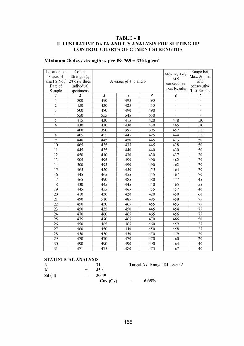
155
TABLE – B
ILLUSTRATIVE DATA AND ITS ANALYSIS FOR SETTING UP
CONTROL CHARTS OF CEMENT STRENGTHS
Minimum 28 days strength as per IS: 269 = 330 kg/cm2
Location on
x-axis of
chart S.No./
Date of
Sample
Comp.
Strength @
28 days three
individual
specimens
Average of 4, 5 and 6
Moving Avg.
of 5
consecutive
Test Results
Range bet.
Max. & min.
of 5
consecutive
Test Results
1 2 3 4 5 6 7
1 500 490 495 495 - -
2 450 430 425 435 - -
3 500 480 490 490 - -
4 550 555 545 550 - -
5 415 430 415 420 478 130
6 430 430 430 430 465 130
7 400 390 395 395 457 155
8 405 425 445 425 444 155
9 440 445 450 445 423 50
10 465 435 435 445 428 50
11 445 435 440 440 430 50
12 450 410 430 430 437 20
13 505 495 490 490 462 70
14 500 495 490 490 462 70
15 465 450 450 455 464 70
16 445 465 455 455 467 70
17 465 490 485 480 477 45
18 430 445 445 440 465 55
19 445 455 465 455 457 40
20 410 430 420 420 450 60
21 490 510 485 495 458 75
22 450 450 465 455 453 75
23 450 435 450 445 454 75
24 470 460 465 465 456 75
25 475 470 465 470 466 50
26 450 465 465 460 459 25
27 460 450 440 450 458 25
28 450 450 450 450 459 20
29 470 470 470 470 460 20
30 490 490 490 490 464 40
31 471 475 480 475 467 40
STATISTICAL ANALYSIS
N = 31 Target Av. Range: 84 kg/cm2
X = 459
Sd () = 30.49
Cov (Cv) = 6.65%

156

157
APPENDIX-2
PLATE 3B

158
APPENDIX-2
PLATE 2 A

159
APPENDIX-3

160
PROFORMA
Test Results of Cement Samples
Name of Factory
Tested at ______________________ Laboratory
ReS.No. Particulars Values for the Month of
Remarks Jan. Feb. Mar. Apr. May
1 No. of test results (n)
2 Av. Compressive strength at
3 3 days (kg/cm2)
4 Standard deviation (Sd)
Co-efficient of variation
(Cv)%
5 Av. Compressive strength at
6 7 days (kg/cm2)
7 Standard deviation (Sd)
Co-efficient of variation
(Cv)%
8 Av. Compressive strength at
6 28 days (kg/cm2)
10 Standard deviation (Sd)
Co-efficient of variation
(Cv)%

161
ANNEXURE – XI
IS: 516 - 1659
Graph showing Correction factor for height / diameter ratio of a core

162
ANNEXURE – XII
STATEMENT SHOWING CAPACITY OF PAVER AND MECHANICAL
TRIMMER
Paver Type Rated Output On Actual Average Output on
Bed Lining Slope Lining Bed Lining Slope Lining
SL-450 x (Gomaco)
or of identical
make
15m3/hr
(or 150m2/hr) for
10cm thick lining
10m3/hr
(or 100m2/hr) for
10cm thick lining
10m3/hr
(or 100m2/hr)
for10cm thick
lining or
(130m2/hr)
7.5m3/hr
(or 75 m2/hr) for
10cm thick lining
SL-750 x (heavier
version)
40m3/hr (or
400m2/hr) for
10cm thick lining
30m3/hr (or
300m2/hr) for
10cm thick lining
22m3/hr (or
220m2/hr) for
10cm thick
lining
15m3/hr
(or 150m2/hr) for
10cm thick lining
Mechanical Trimmer
Type
Rated Capacity of Trimming Average Actual Out put
Gomaco SL 450 T 200m2/hr (2.8cm to 4.0 cm cut in a
single pass) or on depth of cut is about ±
3 to 3.5 cum
60m2/hr (depth of cut in a
single pass was only 2.5 cum.
Gomaco SL-750 T
(Heavy Duty Trimmer)
400m2/hr (with a rated capacity to cut 10
cum in a single pass)
125m2/hr (depth of cut in a
single pass was only 4.0 cum)

163
ANNEXURE – XIII
GOVERNMENT OF RAJASTHAN
IRRIGATION DEPARTMENT
No. F. 30 (14) Irrigation / 96 Dated: 04.11.96
To,
Chief Engineer, Irrigation, Rajasthan / Chief Engineer (Headquarters) / Chief Engineer,
Bisalpur / Chief Engineer ,IDR / Chief Engineer, Mahi Bajaj Sagar Project, Banswara / Chief
Project Director, Sidhmukh Nohar Project / Chief Engineer, Irrigation, North, Hanumangarh.
Additional Chief Engineer, Irrigation Department, Jaipur / Jodhpur / Kota / Udaipur, Director,
IMTI, Kota.
All Superintending Engineers /All Executive Engineers /All Assistant Engineers /All Junior
Engineers, Irrigation Department.
ORDER
In pursuance of the directions issued by the State Government, a committee of officers had
been constituted vide orders of the Chief Engineer, Irrigation. Rajasthan No. 2402 dated
7.8.96 for determination of the norms of inspection of irrigation works by the officers and
staff of the Department. The committee was directed to give its recommendations in this
regard with reference to various categories of works such as maintenance works, construction
works, quality control etc. The report of the committee dated 16.10.96 has been received by
the State Government and has been duly considered. On the basis of these recommendations,
the State Government hereby determines the norms for inspection of all categories of
irrigation works by officers and staff of the Irrigation Department as per details attached
herewith.
Annexure-I determines the norms for inspection by Engineers of the Department having only
maintenance (and no construction works) under their charge. Part A of this annexure deals
with tank irrigation projects and part-B with large canal systems such as Gang, Bhakra, IGNP,
Mahi, Gurgaon and Jawai Canal systems.
Annexure-II determines the norms for inspection and supervision of works by officers and
staff of the Irrigation Department having either construction works (or no maintenance works)
or, having both construction and maintenance works under their respective charge.
Annexure-III determines the norms for the Quality Control units of the Irrigation Departments
and the guidelines to be followed by them.
The assessment of the performance of the officers and staff of the Department in the annual
performance appraisal forms shall be based on the achievement of the norms and determined
by these orders. All officers and staff of the Department are hereby directed to adhere to the
norms as determined herein. It is also reiterated that during such tours and inspections, the
officers and staff concerned shall record their notes in the inspection registers maintained at
each site for which directions have already been issued separately.
C.K. Methew
Secretary to Government
Encl.: a/a. Irrigation Department
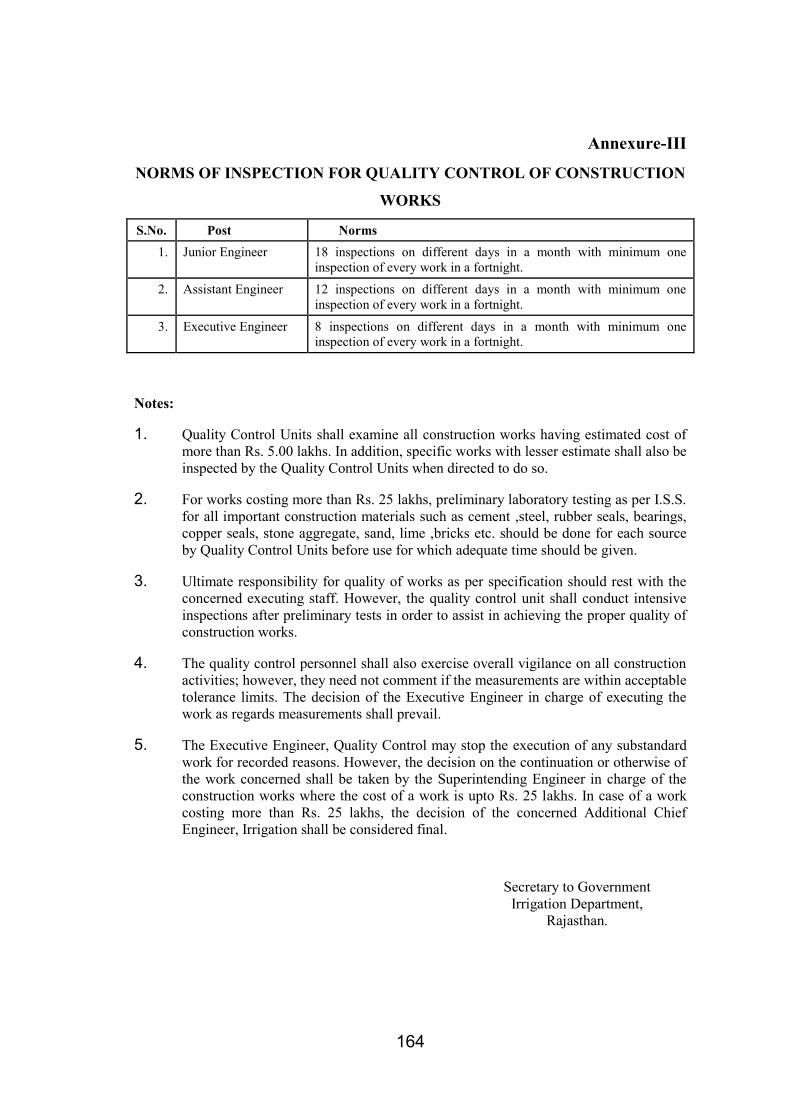
164
Annexure-III
NORMS OF INSPECTION FOR QUALITY CONTROL OF CONSTRUCTION
WORKS
S.No. Post Norms
1. Junior Engineer 18 inspections on different days in a month with minimum one
inspection of every work in a fortnight.
2. Assistant Engineer 12 inspections on different days in a month with minimum one
inspection of every work in a fortnight.
3. Executive Engineer 8 inspections on different days in a month with minimum one
inspection of every work in a fortnight.
Notes:
1. Quality Control Units shall examine all construction works having estimated cost of
more than Rs. 5.00 lakhs. In addition, specific works with lesser estimate shall also be
inspected by the Quality Control Units when directed to do so.
2. For works costing more than Rs. 25 lakhs, preliminary laboratory testing as per I.S.S.
for all important construction materials such as cement ,steel, rubber seals, bearings,
copper seals, stone aggregate, sand, lime ,bricks etc. should be done for each source
by Quality Control Units before use for which adequate time should be given.
3. Ultimate responsibility for quality of works as per specification should rest with the
concerned executing staff. However, the quality control unit shall conduct intensive
inspections after preliminary tests in order to assist in achieving the proper quality of
construction works.
4. The quality control personnel shall also exercise overall vigilance on all construction
activities; however, they need not comment if the measurements are within acceptable
tolerance limits. The decision of the Executive Engineer in charge of executing the
work as regards measurements shall prevail.
5. The Executive Engineer, Quality Control may stop the execution of any substandard
work for recorded reasons. However, the decision on the continuation or otherwise of
the work concerned shall be taken by the Superintending Engineer in charge of the
construction works where the cost of a work is upto Rs. 25 lakhs. In case of a work
costing more than Rs. 25 lakhs, the decision of the concerned Additional Chief
Engineer, Irrigation shall be considered final.
Secretary to Government
Irrigation Department,
Rajasthan.

165
ANNEXURE – XIV
GOVERNMENT OF RAJASTHAN
WATER RESOURCES, PHED, GWD & IGN DEPTTS
No. F1 ( )/PS/WR-PHED-GWD-IGNB/2010 Jaipur, Dated: 27.09.2010
To,
1. Chief Engineer, Quality Control
WR, Jaipur.
2. Addl. Chief Engineer (QC & Vigilance),
IGNP, Bikaner
Sub.: Inspection for QC control as per prescribed norms.
Sir,
Your kind attention is invited to Annexure III of order No. F. 30(14) Irrigation/96
dated 04.11.96 vide which inspection norms were prescribed for the officers posted in the QC
Wing.
The incidents of breaches in Gardada and some other darns in previous few years
indicate that the QC Wing has not been able to exercise requisite quality control checks. Had
the inspection of the works been carried out thoroughly as per norms, such losses were
available. Government has taken it seriously.
It is now decided that close monitoring of the inspections carried out would be done
at Government level. Please take the following action immediately:
1) Depending upon the number of ongoing works, annual inspection norms should be
worked out for each division and target be clearly prescribed.
2) An inspection check list to have thorough technical examination of all technical
aspects of work to ensure requisite quality should be prepared and circulated to all
officers within 15 days. After inspection of work, each inspecting officer would
submit the report in the check list to the next authority within 3 days.
3) Monthly progress report in the enclosed format (Form III) would be sent by you to Pr.
Secretary, WR by 10th of each month.

166
You would also ensure that those officers who fail to carry out the inspections as per
norms are strictly dealt with. The CE (QC) and ACE (QC & Vigilance), IGNP & SE (QC)
would also carry out inspections of work as follows:-
CE QC : Work of all major and medium projects once in 6 months.
ACE (QC), IGNP : All major works once in 6 months.
SE (QC) : (i) All major projects once in a year.
(ii) 50% of medium projects once in a year.
(iii) 5% of minor projects once in a year.
Please ensure compliance of these instructions strictly.
Yours faithfully,
(Ram Lubhaya)
Pr. Secretary, WR & IGND

167
FORM-III
NORMS OF INSPECTION FOR QUALITY CONTROL OF CONSTRUCTION WORKS
Name of District: ...................... Report for the month of: ..............
S. No. Name of the
Zone/Circle/
Division
Designation
of the
inspecting
officer
No.
Posted
No. of
Ongoing
Constructio
n works
above Rs. 5
lacs in the
jurisdiction
Progress of
inspections
done
Status of inspection
note / compliance
made
Status for stoppage of sub standard
works
Status of laboratory at
site
Whether report
submitted to
next higher
officer? (Y/N) T A No. of
Inspection
Notes
issued
No. of
notes of
which
complia
nce
made
No. of
works
instructe
d to be
stopped
due to
poor
quality
No. of
works
actually
stopped
No. of works
where
competent
authority has
given direction
to start the
work
As per
norms
Established
1 2 3 4 5 6 7 8 9 10 11 12 13 14 15
1 CE/ACE
2. SE
3. XEN
4. AEN
i. T - Annual Target.
ii. A - Achievement (up to the reporting months).
iii. Where more than one inspecting officer exist, the annual target would be = No. of officials / officers actually working x the annual target prescribed vide
Annexure - III of order dated 04.11.96.
iv. Total number means total number existing in the district.

168
Portable Electronic Devices
for
Quick on-site measurement
of moisture content, in place density & compaction efficiency
during compaction of subgrade/embankment

169
Steel Screed fitted with Fuel-Operated Vibrator
(Final adjustments being made prior to commencement of
placement of cement concrete lining in canal bed)

170
Vibratory Power Rollers
For
Compaction

171
Compaction of Subgrade on Canal Side Slope
with
Portable Compactor

172
Slip Form Steel Gantry fitted with Vibrators
For
Placement of Cement Concrete lining on side slopes
(Single rail track)

173
View of Slip-Form Steel Gantry for Placement of
Cement Concrete lining on Canal Side Slopes
(Double rail track)

174
Mobile self-Loading, Mixing and Transporting
Concrete Mixer