quality inspection summary 74-50-5b, 6b, 8b, 8b-02 · pulsars have single or continuous (recycle)...
TRANSCRIPT

74-50-5B, 6B, 8B, 8B-02 Pulsar Stimulators 1
QUALITY INSPECTION SUMMARY
74-50-5B, 6B, 8B, 8B-02 Pulsar Digital Stimulators
We have made every effort to manufacture this instrument to the highest quality standards. All assemblies have been thoroughly tested and inspected at the factory as follows:
Initial Assembly Inspection ______ Initial QC Inspection/Calibration ______ 2 Hour Burn-In ______ Final Performance Inspection ______
Packaging Inspection Initials: __________ Date: __________ Items included with this catalog number are labeled and packaged separately in shipping carton.
Description Quantity Checked
Pulsar Stimulator (check one) Model: 5B , 6B , 8B , 8B-02 _______ A602 Instruction Manual _______ *½ Amp 5x20mm Fuses (230V) _______ *1Amp 5x20mm Fuses (115V) _______
* Fuses are pre-installed at factory, as determined by shipping address

74-50-5B, 6B, 8B, 8B-02 Pulsar Stimulators 2


74-50-5B, 6B, 8B, 8B-02 Pulsar Stimulators 4

74-50-5B, 6B, 8B, 8B-02 Pulsar Stimulators 5
“Innovation through collaboration”
Providing Instrumentation and
Apparatus for Cellular Research, Intraoperative Recording, and
Microneurography; Micro-electrodes, Micropipettes, and Needles to the
Neuroscience Community for 30 years.
PULSAR DIGITAL STIMULATORS
74-50-5B, 74-50-6B, 74-50-8B, 74-50-8B-02
FHC Headquarters 1201 Main Street,
Bowdoin, ME, 04287 USA Fax: 207-666-8292
E-mail: [email protected] www.fh-co.com
24 hour technical service
+1-207-666-8190 1-800-326-2905(US & Can)
FHC Europe (TERMOBIT PROD srl)
129 Barbu Vacarescu Str, Sector 2
Bucharest 020272 Romania

74-50-5B, 6B, 8B, 8B-02 Pulsar Stimulators 6

74-50-5B, 6B, 8B, 8B-02 Pulsar Stimulators 7
74-50-5B, 74-50-6B, 74-50-8B, 74-50-8B-02 PULSAR DIGITAL STIMULATORS
TABLE OF CONTENTS
1 OPERATION MANUAL 1.1 FEATURES 1.2 DESCRIPTION 1.3 TECHNICAL SUMMARY 1.3.1 SPECIFICATIONS 1.3.2 CONTROLS / CONNECTORS 1.4 ILLUSTRATIVE EXAMPLES 1.5 OPERATIONAL DESCRIPTION 2 REFERENCE MANUAL 2.1 REFERENCE INFORMATION 2.1.1 PACKAGING 2.1.2 MOUNTING 2.1.3 INSPECTION 2.1.4 POWER CONNECTIONS 2.1.5 WARRANTY 2.1.6 POLICIES 2.1.7 SERVICE 2.2 INSTALLATION 2.4 FUNCTIONS 2.4.1 PULSE GENERATOR FUNCTIONS 2.4.2 6i OUTPUT FUNCTIONS 2.4.3 6b OUTPUT FUNCTIONS 2.4.4 6bp OUTPUT FUNCTIONS
2.4.5 6bp-a/s OUTPUT FUNCTIONS 2.6 FUNCTIONAL CHECKOUT 2.6.1 EQUIPMENT REQUIRED 2.6.2 PULSE GENERATOR CHECKOUT 2.6.3 6i OUTPUT CHECKOUT 2.6.4 6b OUTPUT CHECKOUT 2.6.5 6bp OUTPUT CHECKOUT 2.6.6 6bp-a/s OUTPUT CHECKOUT 3 TECHNICAL MANUAL 3.0 GENERAL DOCUMENTATION INFORMATION 3.1 SPECIFIC PACKAGING DISASSEMBLY INFORMATION 3.2 TECHNICAL DESCRIPTION 3.2.1 PULSE GENERATOR DESCRIPTION 3.2.2 6i OUTPUT DESCRIPTION 3.2.3 6b OUTPUT DESCRIPTION 3.2.4 6bp OUTPUT DESCRIPTION
3.2.5 6bp-a/s OUTPUT DESCRIPTION 3.3 CALIBRATION PROCEDURE 3.3.1 6i OUTPUT CALIBRATION 3.3.2 6b OUTPUT CALIBRATION 3.3.3 6bp OUTPUT CALIBRATION
3.3.4 6bp-a/s OUTPUT CALIBRATION 3.4 MASTER PARTS LISTS 3.5,6 SCHEMATICS & PARTS LAYOUTS
A602

74-50-5B, 6B, 8B, 8B-02 Pulsar Stimulators 8
1 Operational Manual 1.1 Features
VARIETY OF OUTPUT STAGES FOR VIRTUALLY ALL APPLICATIONS
Including
NEW...ASYMMETRIC BIPOLAR VERSION bp-a/s
And
OPTICALLY COUPLED, LINES POWERED ISOLATION -NO BATTERIES
CONSTANT VOLTAGE AND CONSTANT CURRENT MODES ONE MICROSECOND DIGITAL ACCURACY UNIQUE SWITCHING PERMITS SYNCHRONOUS DATA ENTRY COMPACT SIZE FOR RACK MOUNT OR STAND ALONE OPERATION PRICED COMPETITIVELY WITH ANALOG TYPES
1.2 Description
Unique features in a compact, lines powered package make the Pulsar series of stimulators and pulse generators the instrument of choice for brain and peripheral stimulation experiments as well as driving devices for voltage clamp and mechanical/visual/auditory protocols.
Controls are easy to operate and timing signals (TTL) are brought to the front panel for synchronizing other equipment.
Constant voltage or constant current output modes can be selected over the full range of biological requirements from microamps to 200 volts.
Pulsar stimulators actually consist of two separate circuits in a single package. The 6 designates the logic circuitry and i, b, bp and bp-a/s indicate the various output stage options.
Pulsar 6 has controls for CYCLE TIME, DELAY, NUMBER OF TRAIN PULSES, TRAIN INTERVAL, PULSE DURATION, and PULSE AMPLITUDE. Pulsars have SINGLE or CONTINUOUS (recycle) modes and feature a unique 3-position SYNCHRONOUS SWITCH which, when in the OFF position, disconnects the thumbwheel switches even while a program is running, so that new values set are not entered until the end of cycle after the ENTER position is activated. In the third ON position, thumbwheel switch value changes are immediately effected.
Digital values are set on 4-digit thumbwheel switches using the general form XXX.10P where XXX, the significant figures, are the first three digits and P, the exponent, is the fourth.
Additional Pulsar 6 units can be triggered from a master unit to generate complex timing sequences. The illustrative examples demonstrate many of the unique and useful features of the Pulsar stimulators.
The i (isolated) output version is for general purpose stimulating experiments and features 6 constant current (0-10mA) or constant voltage (0-200V) ranges. It is optically coupled, powered by

74-50-5B, 6B, 8B, 8B-02 Pulsar Stimulators 9
an isolated supply; no batteries are required. The output is single polarity with a reversing switch. A capacitor coupled (.47mFd) biphasic output is also included.
Our new bp-a/s output stage has been designed for chronic stimulation or other applications where an asymmetric waveform is required. It features a bipolar, optically isolated; constant voltage (0-150V) or current (0-50mA) output where the amplitude and duration of each phase is adjustable.
The bp output stage has the same output power as the bp-a/s but only a symmetrical bipolar in addition to monopolar, pulse can be generated.
On both the bp and bp-a/s, the second phase is separated by 1-100uSec (internally adjustable).
The power of the bipolar output stages, 150V and 50mA, also makes them ideal for muscle stimulation experiments.
The b output is not isolated and is designed to drive either remote linear or pulse isolators and voltage clamp amplifiers. The output is adjustable from 0 to +10V in two ranges. The b output includes a symmetrical bipolar mode as well as provision for controlling the output amplitude with an external voltage level. A special front panel connector for tapping power to our CCIU-8 isolator is provided.
1.3 Technical Summary
1.3.1 Specifications
Cycle Time: adjustable from 1uSec to 99,900Sec.
Cycle Delay: adjustable from 1uSec to 99,900Sec.
Train Pulses: adjustable from 1 to 999x108 pulses
Train Interval: adjustable from 1uSec to 99,900Sec.
Pulse Duration: adjustable from 1uSec to 99,900Sec.
Pulse Duration 2(bp-a/s only): adjustable from 1uSec to 99,900Sec.
i Output: optically isolated; constant current (1-10,000uA in 3 ranges) or constant voltage (.1-200V in 3 ranges), positive or negative polarity; capacitively coupled (.47mF) biphasic output switch provided.
bp Output: optically isolated; constant current (1-50,000uA in 4 ranges) or constant voltage (.1-150V in 2 ranges), positive, negative or symmetrical bipolar output.
bp-a/s output: optically isolated; constant current (1-50,000uA in 4 ranges) or constant voltage (.1-150V in 2 ranges), positive, negative or asymmetrical bipolar output where the duration and amplitude of each phase is independently adjustable.
b output: ground referenced, constant voltage (.01-10V in 2 ranges), and positive, negative or symmetrical bipolar output.
Power Requirements: 115/230V (switch selected), 50-60Hz, 1A
Pulsar 6i and b Dimensions: 5.5" x 7" x 12" (14 x 18 x 30cm). 8# (3.6kg)
Pulsar 6bp Dimensions: 8.5" x 7" x 12" (21 x 18 x 30cm), 8# (3.6kg)

74-50-5B, 6B, 8B, 8B-02 Pulsar Stimulators 10
1.3.2 Controls / Connectors
Figure 1.3.2. Pulsar 6i, 6b, 6bp and 6bp-a/s front panels
10
98
7
6 5 4 32
1
0
0
0
0
0
0
0
0
0
0
0
0
0
0
0
0
0
0
0
0
0
BOWDOINHAM, ME 04008 USA
BIPHASIC
uSEC uSEC uSEC uSECPULSES
STRTSTP ON SING SYNC TTL
SWITCHESON
OFF
ENTERCONT
EXT ADD GND DELAY DONE
Pulsar 6i
CYCLETIME
PULSEDELAY
TRAINPULSES
TRAININTERVAL
PULSEDURATION
PULSEAMPLITUDE
RUN
NEG
POSOFF
NORM
MODE
.01mA 20V10V
1V1.0mA0.1mA
10
98
7
6 5 4 32
1
0
0 0 0 0 0
0
0
0
0
0
0
0
0
0
0
0
0
0
0
0
CYCLETIME
PULSEDELAY
TRAINPULSES
TRAININTERVAL
PULSEDURATION
MULTIPLIER
X1X.1
Pulsar 6b
PULSES uSECuSEC
RUN
PULSEAMPLITUDE
DONEDELAYGNDADDEXT
CONT ENTER
OFF
SWITCHESONTTLSYNCSINGON
OUTPUT
GROUND
BOWDOINHAM, ME 04008 USA
B-PPOS ON
INT
EXT
OFFNEGOUTPUT
uSECuSEC
STRTSTP
10
98
7
6 5 4 32
1
0
0
0
0
0
0
0
0
0
0
000
0
0
0
0
0
0 0
0
BOWDOINHAM, ME 04008 USA
MODE
15V
1V5mA1.0mA
0.1mA
.01mA
OUTPUT
COM
OUT
ONPOS
OFFNEG
OUTBIPOLAR
EXT AMP
INT AMP
uSECuSEC
STRTSTP ON SING SYNC TTL
SWITCHESON
OFF
ENTERCONT
EXT ADD GND DELAY DONE
CYCLETIME
PULSEDELAY
TRAINPULSES
TRAININTERVAL
PULSEDURATION
PULSEAMPLITUDE
RUN
uSEC uSECPULSES
Pulsar 6bp
MULTIPLIER
4 3
0
12
3456
78
9
10 10
98
7
6 5
21
0
0
0
0
0
0
0
0 0 0
0
0
0
0
0
0
0
0
0
0
0
0
0
0
0
sPulsar 6 bp-a
MODE
1.0mA 5mA
15V
1V0.1mA
.01mA
Neg
Pos
Neg
Pos
Monopolar
Bipolar
SymmetricalBipolar
BOWDOINHAM, ME 04008 USA
STRTSTP ON SING SYNC TTL
EnterCONT
EXT ADD GND DELAY DONE
RUN
MULTIPLIER
PULSE 1AMPLITUDE
PULSE 2AMPLITUDE
TRAININTERVAL
TRAINPULSES
PULSEDELAY
CYCLETIME
PULSE 1DURATION
PULSE 2DURATION
AMPLITUDE REFInt 2
Ext 2
uSEC
OUTPUT
COM
OUT
On
OffExt 1
Int 1
PULSES uSECuSEC uSEC uSEC
SWITCHESOn
Off

74-50-5B, 6B, 8B, 8B-02 Pulsar Stimulators 11
1.4 Illustrative Examples
Figure 1.4a. Pulsar 6i, 6bp and 6bp-a/s output waveforms showing parameters and timing relationships. HEART PACING WITH PULSAR DIGITAL STIMULATORS
PULSE DURATION
PULSEAMPLITUDE
CYCLE TIME
TRAIN PULSES (3)PULSEDELAY
TRAININTERVAL PULSE
DURATION
6bp OUTPUT STAGE(single mode/bipolar output)
Timing Ouputs
SYNC
DELAY
TTL
DONE
TRAIN PULSES (4)
+5V
TRAIN INTERVAL
PULSEAMPLITUDE
+5V
DONE
TTL
DELAY
SYNC
Timing Outputs
6i OUTPUT STAGE(continuous mode/positive output)
START OFNEXTCYCLE
CYCLE TIME
6bp-a/s OUTPUTSTAGE (continuousmode / bipolar output)
Timing Outputs
SYNC
DELAY
TTL
DONE
TRAIN PULSES (3)
+5V
PULSE 1 AMPLITUDEPULSE 1 DURATION
PULSE 2 DURATION
PULSE 2 AMPLITUDE
TRAIN INTERVAL
DELAY

74-50-5B, 6B, 8B, 8B-02 Pulsar Stimulators 12
Pulsar Stimulators' unique input/output characteristics make them ideal for heart pacing experiments. Two units are required; each set in the SINGLE mode. The DONE pulse of each unit is used to trigger the START of the other. Unit I am used to "pace" the tissue; the TRAIN PULSE switches are set to deliver the number of pacing pulses (in the example below: 7). Unit II is used to deliver the "test" pulse(s). The DELAY set on unit II is the test interval. The TRAIN INTERVAL can be set to the same or another interval for the second and subsequent test pulses if required (the example has a second pulse). The DELAY set on Unit I sets the "rest" period prior to the start of another series of pacing pulses. Several output configurations are possible; in the example a monopolar test pulse of identical duration and amplitude to the pacing pulse is required. In that case the TTL output of unit I is connected to the ADD input of Unit II. The output of unit II is connected to the electrode and the amplitude and duration of the pacing and test pulses are set in unit II. If different duration and amplitudes are required for the pacing and test pulses, the outputs of each unit must be summed at the input of a suitable linear amplifier, like our CCIU-8 or bp Isolator, in which case the parameters are independently controlled from each Pulsar unit.
Figure 1.4b. Cardiac stimulation sequence. 1.5 Operational Description
A. PULSE GENERATOR
Many of the special features of the Pulsar series stimulators are a result of a unique circuit designated DOS (Digital One Shot). This circuit is associated with each digitally set parameter and is, in fact, mounted behind each set of thumbwheel switches on the Pulsar front panel.
Each DOS is essentially a settable counter capable of counting down from the number set on the switches. In operation, an output latch remains high until either the number of pulses equal to that set on the decade switches is counted down to zero or the DOS is reset externally.
The diagram below illustrates the Pulsar 6 timing associated with the example front panel switch settings shown. It shows the START button generating a pulse which starts both the CYCLE TIME and CYCLE DELAY DOS's. Both count 1 MHz clock pulses (1uSec interval).
UNIT II OUTPUT
UNIT I DONE out
UNIT II DONE out
UNIT I TTL out
UNIT II TTL out
REPEATPULSE DURATION2mS (not to scale) 500mS
DELAY800mS
TRAIN PULSES (7)
TRAIN INTERVAL500mS
TRAIN INTERVAL 300mSDELAY 398mS
800mS5mA

74-50-5B, 6B, 8B, 8B-02 Pulsar Stimulators 13
When the DELAY DOS reaches its preset count, it triggers the TRAIN INTERVAL, # of TRAIN PULSES, and PULSE DURATION DOS's.
Figure 1.6 Timing Diagram for Pulsar 6 Pulse Generator, CONT mode (In SING mode, DONE output pulse occurs at the completion of the train rather than the completion of the cycle)
The TRAIN INTERVAL DOS counts 1uSec CLOCK pulses to determine the interval between the start of output pulses. When it has counted down it retriggers itself and the PULSE DURATION DOS until inhibited by the DOS which counts the number of pulses to be delivered.
The #of TRAIN PULSES DOS counts the PULSE DURATION DOS done pulses rather than clock pulses. When it has counted down, it inhibits the TRAIN INTERVAL PULSE from retriggering itself.
The CYCLE TIME DOS counts until it reaches the count set on its switches; then a trigger pulse (DONE) is generated which resets all five DOS's. This pulse retriggers the system if the sequence switch is set to CONTINUOUS; in the SINGLE position it is ignored.
The diagram also shows the timing of the SYNC, DELAY, TTL, and DONE outputs. Note also that the ADD input is inserted before the PULSE DURATION DOS and thus signals added will have duration as set on the PULSE DURATION switches. (Note: ADD input pulses occurring during an active train are counted as one of the train pulses). B. Output Stages
All Pulsar output stage options generate an output waveform by appropriate conditioning of the timing pulse generated by the PULSE DURATION DOS (available at the TTL output).
1. 6i output (isolated) - THE DURATION pulse is optically isolated and then fed to an amplifier circuit which generates adjustable constant voltage (0-200V) or constant current (0-10mA) pulses. The output is short circuit protected.
2. 6b output (ground referenced) - The DURATION pulse is used to trigger a circuit which after 10uSec generates a second pulse of equal duration. In the bipolar mode an electronic switch selects a positive voltage reference for the first pulse and a negative voltage reference for the second. The bipolar signal can be amplified to an adjustable +/-10V.
TTL OUTPUT
ADD INPUT
TRAIN DUR DOS
PULSE DUR DOS
TRAIN INT DOS
DELAY OUTPUT
DELAY DOS
DONE OUTPUT
SYNC OUTPUT
CYCLE DOS
START
CLOCK (1MHz)
60uSec
20uSec
10uSec
3 pulses
2uSec
external source

74-50-5B, 6B, 8B, 8B-02 Pulsar Stimulators 14
3. 6bp output (isolated) - The low voltage stage is identical to the b output described above. The signal is then optically isolated and finally fed through an adjustable constant current (0 to +/-50mA) or constant voltage (0 to +/-140V) amplifier.
4. 6bp-a/s output (isolated) - This stimulator has isolated output capabilities identical to the 6bp, but an additional timing circuit provides for further flexibility by permitting independent duration and amplitude settings of each phase of the bipolar output.
74-50-5B, 6B, 8B, 8B-02 Pulsar Stimulators 15
2 Reference Manual 2.1 Reference Information
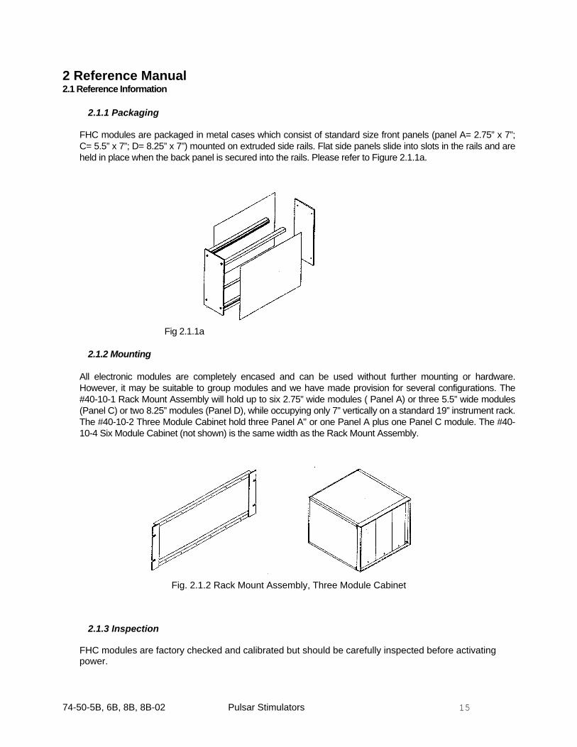
2.1.1 Packaging
FHC modules are packaged in metal cases which consist of standard size front panels (panel A= 2.75” x 7”; C= 5.5” x 7”; D= 8.25” x 7”) mounted on extruded side rails. Flat side panels slide into slots in the rails and are held in place when the back panel is secured into the rails. Please refer to Figure 2.1.1a.
Fig 2.1.1a
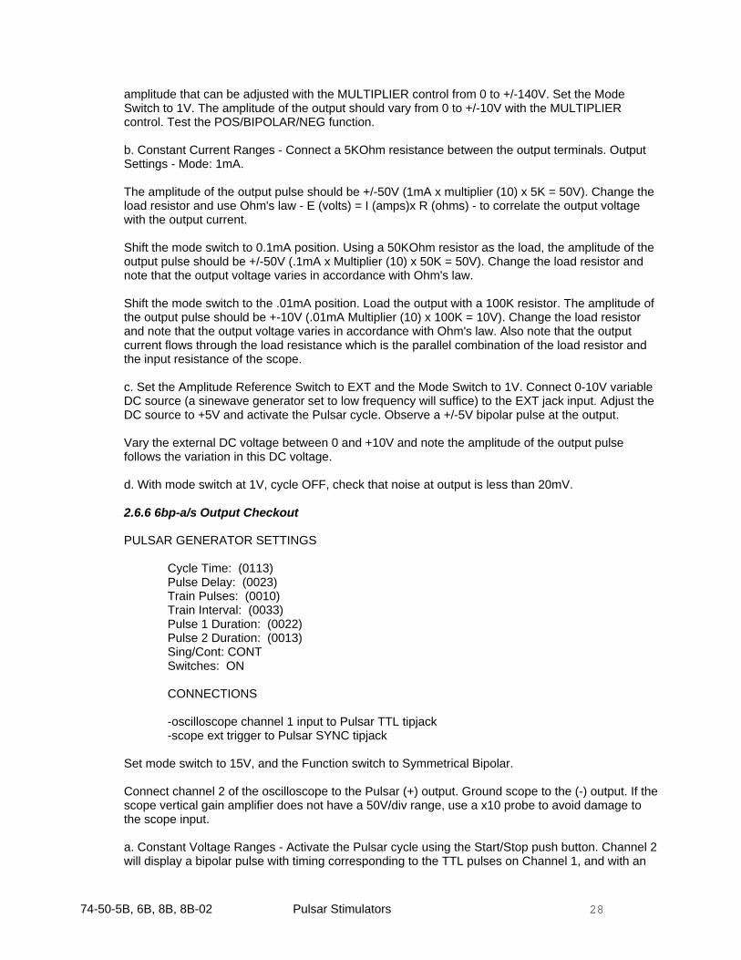
2.1.2 Mounting
All electronic modules are completely encased and can be used without further mounting or hardware. However, it may be suitable to group modules and we have made provision for several configurations. The #40-10-1 Rack Mount Assembly will hold up to six 2.75” wide modules ( Panel A) or three 5.5” wide modules (Panel C) or two 8.25” modules (Panel D), while occupying only 7” vertically on a standard 19” instrument rack. The #40-10-2 Three Module Cabinet hold three Panel A'’ or one Panel A plus one Panel C module. The #40-10-4 Six Module Cabinet (not shown) is the same width as the Rack Mount Assembly.
Fig. 2.1.2 Rack Mount Assembly, Three Module Cabinet
2.1.3 Inspection
FHC modules are factory checked and calibrated but should be carefully inspected before activating power.

74-50-5B, 6B, 8B, 8B-02 Pulsar Stimulators 16
If any exterior damage to the shipping carton is noted, the instrument should be inspected for obvious physical damage.
2.1.4 Power Connections
Before operation, the power entry module on the rear panel must be configured for the line voltage that will be used to power the INSTRUMENT. The instrument has been provided set up for the line voltage determined from the shipping address. PLEASE check the window in the power entry module to be sure this is correct.
CAUTION: Failure to perform this procedure correctly may result in damage to, or improper operation of, the instrument.
The extra fuses required for changing the line voltage are packaged and attached to the power cord.
For operation at 110-120 volts (For example, in North America):
1. Insert the voltage selector insert into the top socket within the recess above the power switch of the power module so that "115" legend is visible when the insert is installed. Press firmly into position.
2. Insert two (2) fuses, each marked 1A into the fuse drawer. (Discard the two fuses marked 500mA;
they are intended for 230 volt operation). 3. Insert the fuse drawer into the power module. ("115" should appear in the fuse drawer window.) 4. Insert the power cord into the receptacle on the power module.
For operation at 220-240 volts (For example, in Australia or Europe):
1. Insert the voltage selector insert into the top socket within the recess above the power switch of the power module so that "230" legend is visible when the insert is installed. (The legend will be rotated 90 degrees). Press firmly into position.
2. Insert two (2) fuses, each marked 500mA into the fuse drawer. (Discard the two fuses marked 1A;
they are intended for 115 volts operation). 3. Insert the fuse drawer into the power module. ("230" should appear in the fuse drawer window). 4. Insert the power cord into the receptacle on the power module.
2.1.5 Warranty
All FHC products are unconditionally guaranteed against defects in workmanship for one year from date of shipment as long as they have been exposed to normal and proper use. Even though the one year warranty may have expired, please contact our Service Department before attempting any repairs or alterations. Many of these repairs will still be performed at the factory at no charge to the customer.
2.1.6 Policies
1. TECHNICAL SUPPORT: It is our policy to provide our customers with the most comprehensive
technical support in the industry. If any questions arise or problems occur, we encourage you to call or write and we promise to promptly and comprehensively respond to your requirements.

74-50-5B, 6B, 8B, 8B-02 Pulsar Stimulators 17
2. TRADE-UP POLICY: It is our policy to offer customers trade-up ability as new and/or expanded
capabilities for their instruments are announced. In many cases, full credit will be given. In general, we will allow 100% credit for two years and depreciate 20% per year thereafter. Please contact our Marketing Department for information relating to your particular situation.
2.1.7 Service
Should service be required, please contact our Service Department for return instructions (207-666-8190). Carefully pack the instrument before returning. Save any packing retainers for future use. Please include a note indicating: 1. The model number and purchase date of the instrument. 2. The person to contact if questions arise. 3. The "symptoms" indicating that repair is necessary. If the instrument is not covered by the warranty, a quotation will be forwarded to the sender detailing the repairs necessary and charges, before repair is begun.
2.2 Installation
NOTE: Every Pulsar is test run for at least 24 hours at the factory using a line voltage of 230V. It is then carefully packed to avoid shipping damage.
As a precaution, please carefully inspect the instrument to ensure that no shipping damage has occurred. ALSO CHECK THAT THE VOLTAGE SELECTOR SWITCH ON THE BACK PANEL IS SET CORRECTLY FOR THE LOCAL LINE CONDITIONS.
2.4 Functions
2.4.1 Pulse Generator Functions
1. Parameter Switches
Digital parameters are entered via 4-digit thumbwheel switches. The format of the numbers is XXX.10P where the X's represent the three significant figures and the exponent is P. The most significant digit is located at the top with the lowest digit being the exponent. When the parameter has a timing function the thumbwheel switch setting corresponds to the timing duration expressed in uSec. For example, a duration of 65 milliseconds can be expressed as 65 x 103uSec. Thus the set-ting on the switches corresponding to the XXX.10P format would read 0653uSec. The duration of 65 milliseconds could also be expressed as 6502. Note that the latter setting allows the values to be changed in .1mSec increments without changing exponents.
NOTE: The largest exponent number that can be entered is "8" i.e. 108. When the exponent is set at "9" the timing scale changes to XXX minutes.
The TRAIN PULSES switches set the number of pulses per cycle. For example, to generate 120 pulses, the thumbwheel switches would be set to 0121 (or 1200).
CYCLE TIME - 4-digit thumbwheel switches to set cycle time between 1 microsecond and 99,900 seconds. The cycle time controls the repetition rate of the output pulse sequence - the selected pulse pattern commences with the beginning of the cycle and the whole sequence may be repeated after an interval controlled by the cycle time switches.

74-50-5B, 6B, 8B, 8B-02 Pulsar Stimulators 18
PULSE DELAY - 4-digit thumbwheel switches to set delay time settings between 1 microsecond and 99,900 seconds. The Delay controls the time interval between the start of the cycle and the generation of the first pulse of the output pulse sequence.
TRAIN PULSES - 4-digit thumbwheel switches to set number of pulses from one output pulse per cycle to 99,900 output pulses per cycle. Note that the minimum train setting is one pulse.
TRAIN INTERVAL- 4-digit thumbwheel switches to set the interval between train pulses from 1 microsecond to 99,900 seconds. Note: the value of the TRAIN INTERVAL set on the switches must be greater than the duration of the output pulse even if the train consists of only a single pulse. If this condition is not satisfied, incorrect pulse timing will result.
PULSE DURATION - 4-digit thumbwheel switches to set output pulse duration from 1 microsecond to 99,900 seconds. On the Pulsar 6bp-a/s, two sets of digital switches permit independent setting of the duration of both phases of the bipolar output pulse.
2. Control Functions
POWER - 2-position toggle switch energizing line power to the instrument.
START - Push button switch to start the Pulsar cycle. If the cycle is running, activating the push but-ton stops the cycle immediately.
SWITCHES - 3-position toggle switch (ON, OFF, ENTER [momentary]) to control the entry of the timing parameters set on the thumbwheel switches to the input registers of the circuitry. When the switch is in the center OFF position, the thumbwheel switches are disengaged from the input registers. The input registers hold any previously entered values and generate pulse sequences in accordance with those values. In the OFF position, the setting on the thumbwheel switches may be changed without disturbing the previously entered timing values.
With the switch set to the ENTER position (momentary) the settings on the thumbwheel switches are entered and latched into the input registers.
With the switch in the ON position, the values set on the thumbwheel switches are entered into the input registers at the beginning of every Pulsar cycle. Thus, with the switches in ON position, any changes made in the timing parameters take effect in the cycle subsequent to the one during which the changes are made.
The process of entering the values into the input registers at the beginning of every cycle takes approximately 10uSec. Thus, with the switches in ON position, the instrument adds a 10 microsecond "lag" period at the beginning of every Pulsar cycle. To avoid this lag, operate the instrument with the switches control in the OFF position and enter new values when required.
SEQUENCE - 2-position toggle switch to control the operation of Pulsar cycle. In the CONTINUOUS mode, once the Pulsar cycle is activated, the end of every cycle will trigger a new cycle indefinitely until stopped. In the SINGLE mode, upon activation, a single cycle is generated.
3. Input / Output Functions
All inputs to the Pulsar are designed to accept TTL level pulses (low: 0 to +0.8V; high: +3 to +5V). The inputs are over-voltage protected to a maximum of 15V and -0.6V.
Pulsar outputs fall under two categories. Digital level outputs are provided to facilitate interconnec-tion and monitoring of timing variables. These outputs are common to all versions of the Pulsar 6.

74-50-5B, 6B, 8B, 8B-02 Pulsar Stimulators 19
The stimulus outputs of the various Pulsar options are described in the section labeled "Output Specifications”.
NOTE: In the process of interconnecting one or more Pulsar units, two TTL outputs should never be connected together or damage to the related integrated circuits will result.
EXTERNAL START INPUT - TTL level tipjack input. A low to high transition at this input can be used to start the Pulsar cycle. As provided from the factory, the Pulsar cycle cannot be stopped from this input. An internal change can be effected to permit an external START/STOP function.
ADD PULSE INPUT - TTL level tipjack input. A low to high transition at this input causes an output pulse of duration set on the thumbwheel switches to appear at the output. This additional output pulse is generated immediately regardless of the state of the Pulsar and is not related to the timing set on the Pulsar (except for the PULSE DURATION switches).
SYNC PULSE OUTPUT - TTL level tipjack output. The SYNC pulse of approximately 1 microsecond duration is generated coincident with the start of the Pulsar cycle.
DELAY OUTPUT - TTL level tipjack output. The DELAY pulse of approximately 1 microsecond duration is generated at the completion of the delay timing within every cycle.
DONE OUTPUT - TTL level tipjack output. In the CONT mode, the DONE pulse of approximately 1 microsecond duration is generated coincident at the end of the Pulsar cycle. In the SING mode, the DONE pulse occurs at the completion of the last stimulus pulse.
TTL OUTPUT - TTL level tipjack output. This output is a TTL pulse coincident with the Pulsar output.
GROUND - Tip jack connected to the system ground.
4. Indicators
All Pulsar 6 units have LED indicators for Power, Run, and Stimulus functions.
POWER LED - Illuminated when power switch is on.
RUN LED - Illuminated when cycle function timer is activated.
STIMULUS LED - Illuminated when the duration timer is activated (when pulse is presented output).
LIMIT (Pulsar 6bp and 6bp-a/s only) - Illuminates when the output amplitude set in any of the current ranges cannot be delivered with the maximum voltage available (140V). 2.4.2 6i Output Functions
(ISOLATED, CONSTANT VOLTAGE OR CURRENT)
AMPLITUDE MULTIPLIER - 1-turn calibrated dial which acts as a 0-10 multiplier for the mode switch setting.
MODE - 6-position rotary switch to select constant voltage (1,10, 20V) or constant current (.01, .1, 1mA) output ranges. The magnitude of the output equals the mode switch setting times the multiplier setting. The maximum constant voltage output is 200V; the voltage compliance in the current ranges is 200V. The output is short circuit protected and is capable of delivering a load current of 20mA in the voltage ranges. With a 100K load the rise time (0-200V) is 2uSec and the fall

74-50-5B, 6B, 8B, 8B-02 Pulsar Stimulators 20
time (200-OV) is approximately 20uSec. With the constant current source the rise and fall time are dependent on the load capacitance.
POLARITY - 3-position toggle switch controls the polarity of the stimulus output. In the OFF position the stimulus output is disengaged from the output binding posts.
COUPLING - 2-position toggle switch controls DC/AC coupling of the stimulus output. In the NORMAL position the stimulus is connected directly to the output. In the BIPHASIC position the output is AC coupled with a 0.47uF capacitor.
OUTPUT - Dual binding posts for the (+) and (-) stimulus outputs.
MONITOR - Dual tipjack output identical to the output/terminals described above.
2.4.3 6b Output Functions
6b OUTPUT STAGE (UNISOLATED, +/- 10V, MONO OR BIPOLAR)
AMPLITUDE MULTIPLIER - 1-turn calibrated dial to adjust the amplitude of the output pulse between 0 and +/- 10V.
ATTENUATOR - 2-position toggle switch to select the amplitude (X1 or X.1) attenuation factor.
The output is ground referenced and protected against short circuit. Maximum drive current is 10mA. The output can drive a maximum capacitive load of about 250pF without exhibiting any instability. Output slew rate is approximately 10V/uSec.
POLARITY - 3-position toggle switch for selecting POSITIVE, BIPOLAR, or NEGATIVE pulses.
In the bipolar position a positive and a negative pulse of equal amplitude and duration (as set on the PULSE DURATION thumb wheel switches) is generated. The separation between the positive pulse and the negative pulse is factory set at 10uSec. To modify this interval, refer to calibration procedure section.
NOTE: When a bipolar pulse is generated, the actual duration of the output pulse is twice that set on the Pulse Duration thumbwheel switch plus 10uSec. THE TRAIN INTERVAL MUST BE GREATER THAN TWICE THE PULSE DURATION SETTING PLUS 10 MICROSECONDS EVEN IF THERE IS ONLY ONE PULSE IN THE TRAIN.
The TTL output reflects the bipolar output by generating a dual TTL level output pulse, the two pulses being separated by 10uSec.
AMPLITUDE REFERENCE - 2-position toggle switch for selecting the voltage reference source for the output. In the INTERNAL position, the calibrated dial and attenuator are effective. In the EXTER-NAL position, a 0 to +10V level can be presented to the EXT input tipjack to control the amplitude of the output. The amplitude of the output equals the amplitude of the external voltage. The X1 and X.1 attenuator and the MULTIPLIER potentiometer have no effect on the output amplitude in the EX-TERNAL position.
OUTPUT - Dual binding posts for output and ground terminals
AUXILIARY OUTPUT - A 5-pin Hex Socket (Amphenol #126-218) is provided for easy interfacing with the FHC CCIU-8 Constant Current Isolation Unit, Catalog no. 74-65-1. The outputs provided on the hex connector are: Pin A, -15V; Pin B, +15V; Pin H, Ground; Pin E, Output; Pin D, No Connection.

74-50-5B, 6B, 8B, 8B-02 Pulsar Stimulators 21
2.4.4 6bp Output Functions AMPLITUDE MULTIPLIER - 1-turn calibrated dial which acts as a 0-10 multiplier for the mode switch setting.
MODE - 6-position rotary switch to select constant voltage (1,15V) or constant current (.01, .1, 1, 5mA) output ranges. The magnitude of the output equals the mode switch setting times the multiplier setting.
The outputs are isolated from earth ground both resistively and capacitively. The 50-60Hz leakage current to ground from either output is less than 15 nanoamps (RMS). The voltage compliance of the output is 125V and it can deliver up to 15mA (DC). Output slew rate is approximately 8 volts/microsecond.
POLARITY - 3-position toggle switch to control the polarity of the output. In the BIPOLAR position a positive and negative pulse of equal amplitude and duration (as set on the thumbwheel switches) is generated. The separation between the positive and negative phase is factory set at 10uSec. To lengthen this setting, refer to the CALIBRATION section.
NOTE: When a bipolar pulse is delivered, the actual duration of the output pulse is twice that set on the Pulse Duration thumbwheel switch plus 10uSec. The TRAIN INTERVAL MUST BE TWICE THE PULSE DURATION SETTING PLUS 10 MICROSECONDS EVEN IF THERE IS ONLY ONE PULSE IN THE TRAIN. The TTL output reflects the bipolar stimulus output by generating two pulses separated by 10uSec.
AMPLITUDE REFERENCE - 2-position toggle switch for selecting the voltage reference source of the output. In the INTERNAL position the calibrated multiplier together with the mode switch setting provides amplitude control. In the EXTERNAL position a 0-10VDC level presented to the EXTERNAL tipjack input times the mode switch setting controls the output amplitude. The relationship between the external voltage and the calibrated dial is 1:1; i.e. 1V external level corresponds to a calibrated dial setting of "1".
OUTPUT SWITCH - 2-position toggle switch disengages the stimulus binding posts.
OUTPUT - Dual binding posts for the output (+) and (-) terminals. 2.4.5 6bp-a/s Output Functions
AMPLITUDE MULTIPLIERS - Two 1-turn calibrated dials (PULSE 1 AMPLITUDE and PULSE 2 AMPLITUDE) which act as 0-10 multipliers for the mode switch setting to independently set the amplitudes of each phase of the output.
POLARITY - Two toggle switches for setting the polarities of the output pulses.
MODE - 6-position rotary switch to select constant voltage (1,15V) or constant current (.01, .1, 1, 5mA) output ranges. The magnitude of the output equals the mode switch setting times the multiplier setting.
The outputs are isolated from earth ground both resistively and capacitively. The 50-60Hz leakage current to ground from either output is less than 15 nanoamps (RMS). The voltage compliance of the output is 125V and it can deliver up to 15mA (DC). Output slew rate is approximately 8 volts/microsecond.
FUNCTION - 3-position toggle switch to select the phasing characteristics of the output. In the Monopolar position, a monophasic output pulse is generated. The duration of the pulse is set on the PULSE 1 DURATION thumbwheels; PULSE 1 AMPLITUDE and polarity switch control the output.

74-50-5B, 6B, 8B, 8B-02 Pulsar Stimulators 22
In the Symmetrical Bipolar position, a two-phase output pulse is generated. Both phases are controlled by the PULSE 1 controls. Following a separation time of 10 microseconds, a second phase is automatically generated that is equal in duration and amplitude, but of the opposite polarity of the first phase.
In the Bipolar position, a two-phase output pulse is also generated, but the duration and amplitude are independently adjustable. The first phase is controlled by the PULSE 1 controls. Following a separation time of 10 microseconds, a second phase is automatically generated, the duration of which is controlled by the PULSE 2 DURATION thumbwheels. PULSE 2 AMPLITUDE, and its polarity switch, control the level of this second phase.
NOTE: The PULSE 2 DURATION, PULSE 2 AMPLITUDE and polarity are only active in the Bipolar mode.
When a Symmetrical Bipolar pulse is delivered, the total actual duration of the output pulse is twice that set on the PULSE 1 DURATION thumbwheel switches plus 10uSec. The TRAIN INTERVAL MUST BE TWICE THE PULSE 1 DURATION SETTING PLUS 10 MICROSECONDS EVEN IF THERE IS ONLY ONE PULSE IN THE TRAIN. The same restriction on TRAIN INTERVAL timing applies to the Bipolar mode, EVEN IF PULSE 2 DURATION IS LESS THAN PULSE 1 DURATION. The TTL output reflects either bipolar mode by generating two pulses, separated by 10uSec, of the length set by PULSE 1 DURATION.
AMPLITUDE REFERENCE - 2-position toggle switch for selecting the voltage reference source of the output. In the INTERNAL position the calibrated multiplier together with the mode switch setting provides amplitude control. In the EXTERNAL position a 0-10VDC level presented to the EXTERNAL tipjack input times the mode switch setting controls the output amplitude. The relationship between the external voltage and the calibrated dial is 1:1; i.e. 1V external level corresponds to a calibrated dial setting of "1".
OUTPUT SWITCH - 2-position toggle switch disengages the stimulus binding posts.
OUTPUT - Dual binding posts for the output (+) and (-) terminals.

74-50-5B, 6B, 8B, 8B-02 Pulsar Stimulators 23
2.6 Functional Checkout 2.6.1 Equipment Required
2 channel Oscilloscope with external trigger Signal Generator (0-10V, .1-1KHz) Decade Resistor Box
NOTE: The operator should thoroughly familiarize himself with the information contained in the operational section, especially as it relates to the setting of digital switches and the operation of the SWITCHES control.
Figure 2.6.1 SYNC, DELAY, and DONE pattern
2.6.2 Pulse Generator Checkout
1. Illustration of continuous and single mode operation, identification of SYNC, DELAY, TTL, and DONE output signals. Note: Users of the Pulsar 6bp-a/s stimulator should set PULSE 2 DURATION to 0000 and set PULSE 1 DURATION to the settings for Pulse Duration given in the following examples.
SCOPE SETTINGS
Sweep: 0.2mSec/div Vertical gain: 5V/div Trigger selector: ext
PULSAR SETTINGS
Cycle Time: 2mSec (0023) Pulse Delay: 0.2mSec (0022) Train Pulses: 1 pulse (0010) Train Interval: 0.2mSec (0022) Pulse Duration: 0.1mSec (0012) Switches: ON Sing/Cont: CONT
6b, 6bp: POS/BIPOLAR/NEG switch to POS 6bp-a/s: Function switch to Monopolar
CONNECTIONS
Pulsar SYNC output to external trigger of oscilloscope Pulsar TTL output to input of oscilloscope channel 1
a TTL OUT
SYNC
DELAY
DONE
b

74-50-5B, 6B, 8B, 8B-02 Pulsar Stimulators 24
a. Activate power and depress the STRT/STOP switch. The pattern as shown in Figure 2.6.1 should result, and the RUN and OUTPUT LED's should light. NOTE: The Ground tip jack on the front panel should not have to be connected to the scope ground since this part of the circuit is not isolated and the scope ground will be connected by virtue of the ground prong on the power plugs. A solid signal should be seen on the scope. If the signal appears to have a floating ground (eg. Signal is not stable, acts like it is not referenced to anything) then there could be a problem with the ground path and the unit should be powered down and all ground connections should be evaluated. Connect channel 2 of the scope to the SYNC output, then the DELAY output, then the DONE output and note the patterns as in Figure 2.6.1.
b. Stop the Pulsar by depressing the STRT/STOP switch. Set the sequence switch to single and restart the Pulsar. Note that only a single cycle is generated for each depression of the STRT/STOP switch, and that the DONE pulse occurs at the completion of the TTL pulse (falling edge).
2. Illustrations of multiple pulse (train) operation and function of switches on/off/enter.
a. Reset the Sequence switch to CONTINUOUS. All other settings and connections as in step 1.
b. Start the Pulsar, then position the switches control in the OFF position. Change the # OF TRAIN PULSES thumbwheels to give two pulses (0020). Note that the output is still as above. Now push the SWITCHES control to ENTER and note that two pulses are generated per cycle. The ENTER position of the SWITCHES control is a momentary position which enters the parameters set on the thumbwheel switches into the Pulsar pulse generator before the start of the next cycle. The ON position of this switch performs this data entry continuously; i.e. any changes made in thumb wheel settings are reflected in subsequent cycles. The OFF position allows the user to alter the thumbwheel set tings without changing output parameters until such changes are entered with the SWITCHES control.
The entry of the thumbwheel settings adds 10uSec to the selected CYCLE TIME. Note that new switch values are entered at the end of each cycle, NOT immediately.
3. Demonstration of ADD and EXT (External Start) inputs:
a. Start the Pulsar using the controls and connections as in step above. In addition, connect the SYNC output to the ADD pulse input.
Note that a pulse is now added to the beginning of the cycle. Note too that it also has the duration that is set on the PULSE DURATION thumbwheels.
b. Stop the Pulsar cycle by depressing the STRT/STOP switch. Disconnect the SYNC pulse and connect an external TTL level signal at a frequency of 100Hz to the ADD input and note that a Pulsar output is generated for each external input pulse even though the Pulsar is not running.
c. Now start the Pulsar cycle and note that the external pulse is still generated asynchronously along with the Pulsar timing pulses. Note also that if an internal and external pulse occur simultaneously, only a single pulse is generated. Add pulses occurring during an active train are counted as train pulses by the stimulator.
d. Set the SING/CONT switch to SING. Connect the external pulse source to the EXT input and note that a single cycle is generated with each external pulse. The CYCLE TIME settings are ignored in the SING mode. The Pulsar generates a DONE output pulse coincident with the trailing edge of the last train pulse generated; i.e. the DONE pulse signals the completion of the train rather than the completion of cycle, as is the case in the CONT mode.

74-50-5B, 6B, 8B, 8B-02 Pulsar Stimulators 25
An internal modification can be effected to cause the Pulsar to shut down on the second pulse. In other words, alternate EXT pulses result in cycle on/ cycle off operation like the STRT/STOP push button.
The above examples utilize relatively "fast" operation of the Pulsar to facilitate examination of the timing sequence and SYNC, DELAY, TTL and DONE outputs. To illustrate slower settings, set the Pulsar as follows:
Cycle Time: 10Sec (1005) Pulse Delay: 1Sec (0105) Train Pulses: 3 (0030) Train Interval: 1.5Sec (0155) Pulse Duration: 1Sec (0016) Sing/Cont: CONT Switches: ON
Activate the Pulsar and watch the output LED indicator to verify delivery every 10 seconds of three one second pulses delivered after a delay of one second in 1.5 second intervals.
All timing and input/output functions for the Pulsar 6 pulse generator section have now been demonstrated. Before proceeding to the next section it will be instructive to completely familiarize yourself with the controls thus far illustrated by setting up timing sequences like those required for your experiments.
IMPORTANT: It is possible to arrange the Pulsar thumbwheels in such a manner that makes it impossible for the instrument to respond correctly.
In General: CYCLE TIME MUST be set long enough to accommodate the sum of the times required to execute the set PULSE DELAY and # of TRAIN PULSES x TRAIN INTERVAL plus the 10 microseconds required to read the switch data (with SWITCHES set to ON). TRAIN INTERVAL sets the time between the start of pulses within a train - not the interval between pulses. Therefore TRAIN INTERVAL MUST be greater than PULSE DURATION, EVEN IF THERE IS ONLY ONE PULSE in the "train" (# OF TRAIN PULSES set at 0010). With the Pulsar 6b or 6bp set to deliver a bipolar output, TRAIN INTERVAL MUST be set greater than 10uSec + 2 x PULSE DURATION, again, even if the "train" only contains a single bipolar pulse. With the Pulsar 6bp-a/s set to deliver either a Symmetrical Bipolar or Bipolar pulse, TRAIN INTERVAL must always be set greater than 10uSec + 2 x PULSE 1 DURATION or 10uSec + PULSE 1 DURATION + PULSE 2 DURATION (whichever is longer).
Unless the timing conditions listed above are followed, the Pulsar output will be unpredictable.
2.6.3 6i Output Checkout
PULSAR SETTINGS Cycle Time: (0113) Pulse Delay: (0023) Train Pulses: (0010) Train Interval: (0033) Pulse Duration: (0013) Sing/Cont: CONT Switches: ON

74-50-5B, 6B, 8B, 8B-02 Pulsar Stimulators 26
CONNECTIONS
-oscilloscope channel 1 input to Pulsar TTL tipjack -oscilloscope channel 2 input to Pulsar (+) output -oscilloscope ground to Pulsar (-) output -scope ext trigger to Pulsar SYNC tipjack
Pulsar 6i Output Settings: Mode: 20V, Multiplier Dial: 10, Coupling: Normal, Polarity: positive
a. Activate the Pulsar cycle with the STRT/STOP push button. Observe that Channel 1 displays a TTL level pulse of duration 1mSec occurring 2mSec after the start of the Pulsar cycle.
b. Observe that Channel 2 displays a 200V pulse with timing characteristics identical to the waveform displayed on Channel 1.
c. Note the effect of the mode switch settings of 10V and 1V. Note the effect of the multiplier setting on the output amplitude.
d. Note the effect of the POS/OFF/NEG polarity switch settings.
e. Test the effect of the NORMAL/BIPHASIC function. In the Biphasic mode, the output is AC coupled. The effect will be more noticeable if a 50K resistor is connected between the (+) and (-) outputs.
f. Turn off the Pulsar. Connect a decade resistor box set at 1KOhm between the (+) and (-) outputs. Pulsar Output Settings: Mode: 1mA; Multiplier Dial: 10; coupling: normal; polarity: pos.
g. Start the Pulsar cycle and note that the amplitude of the output pulse is 10V (1mA X Multiplier (10) x 1KOhm = 10V).
Test the effect of changing the load resistance. The amplitude of the pulse will vary in accordance with Ohm's law: E (volts)=I(amps) R (ohms) until E reaches 200V, the output compliance voltage of the Pulsar 6i.
h. With the multiplier set at 10, set the mode switch to 0.1mA. Load the stimulus output with 10K. Observe that the amplitude of the output waveform will be 10V. (0.1mA x Multiplier (10) x 10K = 10V). Test the effect of changing the load resistance. The amplitude of the output will vary in accordance with Ohm's law.
i. With the multiplier set at 10, set the mode switch to 0.01mA. Load the stimulus output with 100K. Observe the amplitude of the output waveform. It will be 10V (0.01mA x Multiplier (10) x 100K = 10V). Test the effect of changing the load resistance. The amplitude of the output will vary in accordance with Ohm's law.
j. Note that the polarity and switch operates as in the voltage ranges, but that the output coupling switch MUST be in NORMAL for the constant current ranges to function properly.
k. With mode switch at 1V, cycle OFF, check that noise at output is less than 20mV.
2.6.4 6b Output Checkout
PULSAR GENERATOR SETTINGS Cycle Time: (0113) Pulse Delay: (0023) Train Pulses: (0010) Train Interval: (0033)

74-50-5B, 6B, 8B, 8B-02 Pulsar Stimulators 27
Pulse Duration: (0013) Sing/Cont: CONT Switches: ON
CONNECTIONS -oscilloscope channel 1 input to Pulsar TTL tipjack -scope ext trigger to Pulsar SYNC tipjack Connect channel 2 of the oscilloscope to the Pulsar output terminal. Pulsar 6 output settings: Multiplier: x10; Attenuator: x1; Polarity: BIPOLAR; Amplitude Reference: INT a. Activate the Pulsar cycle. Channel 2 should display a +/-10V bipolar pulse corresponding in timing to the TTL pulse displayed on Channel 1. b. Test the X1 and X.1 attenuator and calibrated multiplier. Check the POS/BIPOLAR/NEG function. c. Connect a variable DC source (a sinewave generator on low frequency will suffice) set at +10V to the EXT tipjack input. Set the Amplitude Reference Switch to EXT AMP. Channel 2 should display a bipolar pulse the amplitude of which will vary with the external voltage source. d. With a scope probe check for presence of the following signals on the hex connector-
Pin A, -15 volts Pin B, +15 volts Pin H, Ground Pin D, No Connection Pin E, Stimulus Output
e. With mode switch at 1V, cycle OFF, check that noise at output is less than 20mV.
2.6.5 6bp Output Checkout
PULSAR GENERATOR SETTINGS Cycle Time: (0113) Pulse Delay: (0023) Train Pulses: (0010) Train Interval: (0033) Pulse Duration: (0013) Sing/Cont: CONT Switches: ON
CONNECTIONS -oscilloscope channel 1 input to Pulsar TTL tipjack -scope ext trigger to Pulsar SYNC tipjack
Set mode switch to 15V.
Connect channel 2 of the oscilloscope to the Pulsar (+) output. Ground scope to the (-) output. If the scope vertical gain amplifier does not have a 50V/div range, use a x10 probe to avoid damage to the scope input.
a. Constant Voltage Ranges - Activate the Pulsar cycle using the Start/Stop push button. Channel 2 will display a bipolar pulse with timing corresponding to the TTL pulses on Channel 1, and with an
74-50-5B, 6B, 8B, 8B-02 Pulsar Stimulators 28
amplitude that can be adjusted with the MULTIPLIER control from 0 to +/-140V. Set the Mode Switch to 1V. The amplitude of the output should vary from 0 to +/-10V with the MULTIPLIER control. Test the POS/BIPOLAR/NEG function.
b. Constant Current Ranges - Connect a 5KOhm resistance between the output terminals. Output Settings - Mode: 1mA.
The amplitude of the output pulse should be +/-50V (1mA x multiplier (10) x 5K = 50V). Change the load resistor and use Ohm's law - E (volts) = I (amps)x R (ohms) - to correlate the output voltage with the output current.
Shift the mode switch to 0.1mA position. Using a 50KOhm resistor as the load, the amplitude of the output pulse should be +/-50V (.1mA x Multiplier (10) x 50K = 50V). Change the load resistor and note that the output voltage varies in accordance with Ohm's law.
Shift the mode switch to the .01mA position. Load the output with a 100K resistor. The amplitude of the output pulse should be +-10V (.01mA Multiplier (10) x 100K = 10V). Change the load resistor and note that the output voltage varies in accordance with Ohm's law. Also note that the output current flows through the load resistance which is the parallel combination of the load resistor and the input resistance of the scope.
c. Set the Amplitude Reference Switch to EXT and the Mode Switch to 1V. Connect 0-10V variable DC source (a sinewave generator set to low frequency will suffice) to the EXT jack input. Adjust the DC source to +5V and activate the Pulsar cycle. Observe a +/-5V bipolar pulse at the output. Vary the external DC voltage between 0 and +10V and note the amplitude of the output pulse follows the variation in this DC voltage.
d. With mode switch at 1V, cycle OFF, check that noise at output is less than 20mV.
2.6.6 6bp-a/s Output Checkout
PULSAR GENERATOR SETTINGS Cycle Time: (0113) Pulse Delay: (0023) Train Pulses: (0010) Train Interval: (0033) Pulse 1 Duration: (0022) Pulse 2 Duration: (0013) Sing/Cont: CONT Switches: ON
CONNECTIONS -oscilloscope channel 1 input to Pulsar TTL tipjack -scope ext trigger to Pulsar SYNC tipjack
Set mode switch to 15V, and the Function switch to Symmetrical Bipolar. Connect channel 2 of the oscilloscope to the Pulsar (+) output. Ground scope to the (-) output. If the scope vertical gain amplifier does not have a 50V/div range, use a x10 probe to avoid damage to the scope input. a. Constant Voltage Ranges - Activate the Pulsar cycle using the Start/Stop push button. Channel 2 will display a bipolar pulse with timing corresponding to the TTL pulses on Channel 1, and with an

74-50-5B, 6B, 8B, 8B-02 Pulsar Stimulators 29
amplitude that can be adjusted with the PULSE 1 AMPLITUDE MULTIPLIER control from 0 to +/-140V. Set the Mode Switch to 1V. The amplitude of the output should vary from 0 to +/-10V with the MULTIPLIER control. Test the operation of the Pos/Neg polarity switch. b. Constant Current Ranges - Connect a 500 Ohm resistance between the output terminals. Output Settings - PULSE 1 AMPLITUDE MULTIPLIER: x10; MODE: 5mA. The amplitude of the output pulse should be +/-25V (5mA x multiplier (10) x 500 = 25V). Change the load resistor and use Ohm's law - E (volts) = I (amps) x R (ohms) - to correlate the output voltage with the output current. With the multiplier set at 10, shift the MODE switch to 1mA position. Using a 5KOhm resistor as the load, the amplitude of the output pulse should be +/-50V (1mA x Multiplier (10) x 5K = 50V). Change the load resistor and note that the output voltage varies in accordance with Ohm's law. Note that above a load resistance of about 14KOhms, the compliance voltage of the stimulator limits further increases in output voltage and the LIMIT LED lights. With the multiplier set at 10, shift the MODE switch to 0.1mA position. Using a 50KOhm resistor as the load, the amplitude of the output pulse should be +/-50V (.1mA x Multiplier (10) x 50K = 50V). Change the load resistor and note that the output voltage varies in accordance with Ohm's law. With the multiplier set at 10, shift the MODE switch to the .01mA position. Load the output with a 100K resistor. The amplitude of the output pulse should be +-10V (.01mA x Multiplier (10) x 100K = 10V). Change the load resistor and note that the output voltage varies in accordance with Ohm's law. Also note that the output current flows through the load resistance which is the parallel combination of the load resistor and the input resistance of the scope. d. Set the AMPLITUDE REF switch to Ext 1 and the MODE Switch to 1V. Connect 0-10V variable C source (a sinewave generator set to low frequency will suffice) to the EXT jack input. Adjust the DC source to +5V and activate the Pulsar cycle. Observe a +/-5V bipolar pulse at the output. Vary the external DC voltage between 0 and +10V and note the amplitude of the output pulse follows the variation in this DC voltage. Return the switch to Int 1.
e. Set the Function switch to Bipolar. The output pulse now has two independently adjustable phases. Use PULSE 1 AMPLITUDE and its polarity switch to vary the first phase, and PULSE 2 AMPLITUDE and its polarity switch to vary the second phase. Note that in the Bipolar mode the TTL output consists of a double pulse, both equal in length to the PULSE 1 DURATION.
f. With mode switch at 1V, cycle OFF, check that noise at output is less than 20mV.

74-50-5B, 6B, 8B, 8B-02 Pulsar Stimulators 30
3 Technical Manual 3.0 General Documentation Information
It is our policy to provide comprehensive product documentation with our instruments. Section 3 of our instruction information includes calibration procedures, schematics, and parts layouts. We also maintain a service record file on each product, information of which is available to any instrument owner if in the future he should experience problems.
Parts layouts are provided for all relevant assemblies. These layouts include component values and circuit numbers unique to the assembly. In those cases where the density of the assembly is too high a separate drawing with circuit numbers is included. Complete schematics are also provided for each instrument. Schematics include all components of an instrument and as such, one schematic may include two or more assemblies, e.g. front panel and captive circuit board assemblies. Whenever possible assemblies are separated or designated on schematics. Schematics, in addition to listing component values include circuit numbers. Because circuit numbers are unique to each assembly, the same circuit number e.g C10 may be used twice on a schematic referring in one place to a 10 pF capacitor on a front panel switch and in another to a .47mF PCB mounted capacitor. However, functional considerations should remove any ambiguity. Schematics are referenced by the instrument catalog number followed by a code which lists the total number of pages which constitute the complete instrument schematic i.e. 1/2, 2/2. Assemblies are referenced by the assembly number followed by the number of pages code. In those situations in which a printed circuit board is wired to another assembly, for example a front panel, the identifying interconnections, wire colors, etc. are included with the front panel assembly.
3.1 Specific Packaging Disassembly Information
Pulsar stimulators are packaged in metal cases described in Section 2.1.1. To gain access to the interior of the Pulsar, remove the 4 Philips head screws securing the top left and right extruded side rails to the front panel and back panel (Refer to drawing No. 4010C1.00). Remove the two rails and top panel. Loosening the corresponding 2 screws on the bottom of the front panel will facilitate removal of side panels as well as the printed circuit boards. As shown in drawing No. 4010C1.00, the circuitry of the Pulsars is contained on 5 printed circuit boards, each of which plugs into a mating connector, attached to a "mother-board" which is mounted on the bottom panel. Each board also contains a set of 4 thumbwheel switches which protrude through corresponding slots in the front panel. When removing or installing these boards, the front panel must be moved forward to provide clearance for these thumbwheel switches. In addition to the 5 mother-board mounted circuit boards, the Pulsar 6bp also contains a high voltage output board mounted on the right side panel.
3.2 Technical Description
3.2.1 Pulse Generator Description
The Pulsar series of stimulators can be divided into three major sections. A. Ground Referenced Power Supplies B. Logic Generator Timing and Control Circuitry C. Output Circuitry and Isolated Power Supplies The table in drawing 4010C1.00 in the PARTS LAYOUTS section (3.6) lists the various assemblies for all Pulsar configurations.

74-50-5B, 6B, 8B, 8B-02 Pulsar Stimulators 31
A. Ground Referenced Power Supplies The line voltage (115-230V) is fused with (2) 250V/1A Slo-Blo fuses and connected to a split primary transformer. The secondaries of which supply the AC power required by the ground-referenced DC power supplies contained on the daughter board mounted in slot 1 of the Pulsar. These consist of a 5V, 1.75A supply based on a LM323 regulator (IC A); a +/-15V supply based on a 7815 (IC B) and a 7915 (IC C) regulator; and a -12V supply formed by a 12V zener diode and Q1, a series pass transistor. The Pulsar 6i does not include the +/-15V supply. B. Timing and Control Circuitry The timing functions of the Pulsar 6 series of stimulators are derived from five independent, but identical, circuits referred to as Digital Once Shots, (DOS). The Cycle Time, Delay, # of Train Pulses, Train Interval and Pulse Duration parameters each have an associated DOS. The DOS uses a crystal controlled master clock as the basis for deriving accurate time periods. CLOCK: The crystal controlled clock oscillating at 10MHz is located on the card in slot 3 (Schematic 70-50-X 9/9). The 10MHz is divided down to a 1MHz clock by a 7490 counter (IC P) and buffered by dual inverters. The clock is distributed to all boards via the mother board. DOS (Schematic 70-50-X 2/9): The DOS timing parameters are entered via thumb wheel switches to a set of 74192 and 7475 IC's (A, B, C, and D). These IC's act as latches, loading the values set on the switches whenever a SET pulse occurs. The loaded values appear at the inputs of IC's E, F, and G. The occurrence of a reset pulse clears the DOS outputs and all counters, as well as loading in the value of the exponent setting into latch IC H.
A start pulse sets the RS flip flop formed by IC M. This enables the clock to be gated to the decade divider IC L and sets the Q output of the DOS high. IC L divides 1MHz clock by the power of 10 selected by the exponent thumbwheel switch. For example, if the exponent thumbwheel is set to 6, IC L divides the 1MHz clock to one of 1Hz.
This divided clock is fed to the chain of counters G, F, and E, which have previously loaded in the 3 significant digits set on the front panel. The values set by the thumbwheels are counted down until all three counters read zero. Then an under-count pulse is issued by the most significant count IC E. For example, if the significant digits had been 111, and the clock speed is 1Hz, counter G would zero after 1 second, counter F would zero after 11 seconds and counter E would zero after 111 seconds. This would provide the desired 111 second time period.
The undercount pulse from E triggers one shot K which generates a timing "done" pulse and also resets the RS flip flop formed by M, which had been set by the start pulse. Resetting the flip flop causes the Q (gate output) of the DOS to go to the OFF or low state and disables the 1MHz clock.
CONTROL CIRCUITRY: The cycle start/stop push button is debounced by IC J (Schematic 70-50-X 8/9) and every operation of the switch generates a 200nSec pulse labeled "START". The "START" pulse toggles flip flop IC M (Schematic 70-50-X 9/9). If the Pulsar cycle is off when the start switch is activated, the flip flop generates a 200nSec pulse at the output (pin 5) of IC N. The line labeled SET ALL is high. In the "enter" or "on" position SET ALL is low. With SET ALL held low (SWITCHES in ON position) the 200nSec start pulse generated by N fires one shot G whose output (pin 4) is a 10uSec reset pulse. The reset pulse is distributed to all DOS's via the line labeled RESET. This initializes and loads all DOS's. At the trailing edge of the reset pulse IC G initiates a 200nSec cycle start pulse (pin 12). So long as SWITCHES is ON, the reset pulse always precedes cycle start pulses. If SWITCHES is used to momentarily load all DOS parameters via the SET ALL line, the cycle start is preceded by the reset pulse the first time it is activated. The first cycle start pulse resets the SET ALL flip flop (IC I). This allows subsequent cycle starts to bypass the 10uSec reset one shot.
74-50-5B, 6B, 8B, 8B-02 Pulsar Stimulators 32
The cycle start pulse starts the cycle and delay DOS. At the end of the Delay period, the Delay done pulse (Schematic 70-50-X 9/9) is used to start the # of Train Pulses DOS, the Train Interval DOS and the Pulse Duration DOS. The # of Train Pulses DOS counts duration done pulses keeping track of the number of duration pulses generated by the train. The train interval DOS retriggers itself and the Duration DOS so long as the set number of pulses in the train have not been generated. When the number of duration pulses set on the # of Train Pulses DOS have been generated, the gate output of this DOS inhibits further retriggering of the train interval and pulse duration DOS's.
After the period set on the cycle DOS has been timed, the cycle done pulse is generated (In the SING mode, the DONE pulse is generated at the completion of the train). The cycle done pulse together with the line labeled CONT determine if the cycle done retriggers the cycle start one shot. The rest of the circuitry contained on the card in slot 2 performs buffering of the input signals EXTERNAL START and ADD and the output signals SYNC, DELAY DONE, TTL and CYCLE DONE.
3.2.2 6i Output Description
The circuitry for the Pulsar 6i output and its isolated high voltage power supply is located on the daughter board attached to the card in slot 5. Refer to drawing 1015H1.00 and schematic 70-50-X 2/9. 1. Isolated Power Supplies A special transformer is used to provide the AC supply voltages required for the output stage while providing isolation from power line ground. The output of the isolation transformer is full wave rectified, filtered and fed into a series pass regulator with feedback, consisting of comparator element Q2 and the pass transistor Q1. The output voltage of the regulator is compared against a fixed reference (75V zener diode in the emitter of Q2). Q2 controls the base drive of Q1 so as to maintain a constant regulator output depending on the position of Trimmer T1 which is used to adjust the output voltage of the regulator to 200V. Q3 provides current limiting of the high voltage supply to approximately 40mA. Separate secondary windings on the isolation transformer supply appropriate voltages to the isolated low voltage (+/-15V) power supply comprising a center-tapped full wave rectifier and regulators IC C and D. 2. 6i Output Circuit Description The TTL level output of the Pulse Duration DOS is photo optically isolated by IC A and converted, through Q8, to an isolated signal whose amplitude varies from 0 to 10V depending on the setting of the MULTIPLIER control. This signal drives a voltage-to-current converter formed by op-amp IC B with FET Q7. Q6 serves as a transconductance multiplier in this configuration. The output of this converter stage is a constant current equal to the input voltage divided by Q7's switch selectable source resistor, and is switched to the Pulsar 6i output terminals in each of the three constant current ranges of the stimulator. The compliance voltage of this circuit is approximately equal to the high voltage isolated supply of +200V. In the three constant voltage ranges, the output of this converter is internally switched to a precision 20KOhm load resistance and the voltage across this resistance is current-amplified by emitter followers Q4 and Q5 to form the output of the stimulator. The maximum output current in this mode is limited by the power supply to approximately 40mA.

74-50-5B, 6B, 8B, 8B-02 Pulsar Stimulators 33
3.2.3 6b Output Description
The circuitry for the 6b output stage is located on the card in slot 5. Refer to drawing 1025D1.01 and schematic 70-50-X 4/9. The duration start pulse is input to pin 9 of IC N and passes on through pin 11 of IC N to start the Duration DOS. When the Duration Done pulse appears at the end of the Duration period, one shot Q generates a 10 microsecond separation time. After 10uSec one shot R generates a second duration start pulse. The Duration DOS thus generates two pulses of the set pulse width. Note that IC P prevents dual Duration done pulses from reaching the # of Train Pulses DOS. The Pulsar reset pulse clears the dual flip flop IC O. The duration start pulses toggle the flip flops changing their outputs such that the first Duration gate pulse appears at pin 8 of IC S and the second Duration gate pulse appears at pin 11 of IC S. The attenuator switch selects a +10V or +1V reference voltage. Op amp X buffers the reference voltage and op amp W creates a negative reference voltage of equal magnitude. Op amp V together with the FET switch IH5018 form the electronic switch. For the duration that the pulses output pin 8, IC S is high, the amplitude of the output of V is equal to the negative reference voltage. For the duration that the pulsed output of pin 11 of IC V is high, the output of op amp U is equal to the positive reference voltage. With neither output of IC S high, the output of op amp V is zero.
3.2.4 6bp Output Description
Circuit Description: The Pulsar 6bp output stage consists of one printed circuit card, mounted in slot 5, that is identical to that used as the output for the Pulsar 6b; that is, it produces a bipolar, 0-10V, ground-referenced waveform. In addition, the Pulsar 6bp provides circuitry, contained on a card mounted on the right side panel of the instrument, which converts this signal to one that is isolated from power line ground and which can be used in either constant current or constant voltage modes at voltages up to +/-140V. The slot 5 card is shown in drawing 1025D1.01 and schematic 70-50-X 4/9. The output circuitry is shown in drawing 1238D1.02 and schematics 70-50-X 5/9, 70-50-X 6/9, and 70-50-X 7/9. Isolated AC power for this circuitry is derived from a special transformer mounted on the back panel. Complementary +/-145V series regulators are formed by Q1-4. IC's A and B regulate the isolated +/-15V supplies. Unisolated +/-15V power for some of the circuitry on this board is supplied by the main Pulsar power supply located in slot 1. The unisolated waveform is fed to the input of IC I, a unity gain buffer, the output of which drives IC C, a photo isolator. Transistor Q5 provides the bias current of 6mA to the isolator emitters. The output of IC C is differentially amplified by IC D, whose output is identical to the input signal except that it is now isolated from ground. A high voltage op amp, IC F, provides the final output. In either of the two constant voltage modes, it is configured as a non-inverting amplifier with a voltage gain of 1 or 15. In the four constant current modes, it is configured as a voltage-to-current converter with IC E providing buffering of the voltage applied to the load impedance before feedback to the non-inverting summing input of IC F. The voltage-to-current scaling factor is determined by the switch selectable precision resistors in series with the output. A circuit is provided to indicate when the Pulsar output current is being limited to less than selected as a result of the maximum voltage swing obtainable from IC F (compliance voltage). If the output voltage of IC F gets to within about 7V of either the positive (+145V) or negative (-145V) power supply voltage, one of the isolators, IC G or IC H, will stop conducting. This causes transistor Q8 to turn on, illuminating the front panel LIMIT LED.
74-50-5B, 6B, 8B, 8B-02 Pulsar Stimulators 34
3.2.5 6bp-a/s Output Description
Circuit Description: The Pulsar 6bp-a/s stimulator utilizes three circuit cards to generate the output. The Slot 5 card is a DOS that times the duration of Pulse 1. The card in Slot 6 contains a DOS that times Pulse 2 Duration, the control logic that generates the proper type of pulse as set by the function switch, and the analog circuitry necessary to generate a +/- 10 volt, ground-referenced (non-isolated) pulse. The output from this card drives the final output card, mounted on the right side panel. This output card is identical to the Pulsar 6bp output board described in Section 3.2.4. The Slot 6 card receives a command from the system controller to start the pulse duration timing at IC N, pin 9. This event always starts the timing of the Slot 5 card (PULSE 1 DURATION) and results in a gating signal being applied to pin 1 of IC X that is equal in duration to the PULSE 1 DURATION thumbwheels. The completion of this timing is signaled to IC Q, pins 9 and 5. Subsequent events depend on the setting of the Function switch. In the Monopolar mode, the Duration 1 Done pulse is steered through ICs Q, P, and U to the motherboard Duration Done line. In the Symmetrical Bipolar mode, this pulse is instead steered back to restart, after a 10 microsecond pulse separation delay generated by IC R, the PULSE 1 DURATION DOS. For this second time period, pin 8 of IC X is gated on for the duration set on the PULSE 1 DURATION thumbwheels. In the Bipolar mode, the initial done pulse from the PULSE 1 DURATION DOS is steered to start the timing period of the PULSE 2 DURATION DOS, located on the Slot 6 PCB. Again, pin 8 of IC X is gated on for this period. IC X is an analog switch which, depending on the state of its digital inputs (pins 1 and 8), connects either IC W or IC Y to IC AB, the final output operational amplifier. The output of IC W is a DC voltage between -10V and +10V depending on the setting of the PULSE 1 AMPLITUDE MULTIPLIER and its associated polarity switch (or, alternatively, the input to Ext 1 AMPLITUDE REF). As described above, this voltage is always gated on during the first phase of the output pulse. In the Symmetrical Bipolar and Bipolar modes, IC X switches the output of IC Y to IC AB. IC Y is another analog switch, controlled by the Function switch. In the Symmetrical Bipolar mode, it connects the output of IC V, an inverted version of the PULSE 1 AMPLITUDE, to IC X. In the Bipolar mode, the output of IC AA, a DC voltage set by the PULSE 2 AMPLITUDE controls is instead switched through. The +/- 10 volt output of IC AB drives the final output circuitry (see 3.2.4) which generates the isolated stimulator output. 3.2.6 Motherboard Pin Assignments
MOTHER BOARD - PIN USE
Pin # Name Type 1 2 Cycle Time Decrement * 3 4 Delay Decrement * 5 6 Train Pulses Decrement * 7 8 Train Interval Decrement * 9 10 Pulse Duration Decrement * 11 Cycle Time Increment * 12

74-50-5B, 6B, 8B, 8B-02 Pulsar Stimulators 35
Pin # Name Type 13 Pulse Delay Increment * 14 15 Train Pulses Increment * 16 17 Train Interval * 18 19 Pulse Duration Increment * 20 21 Cycle Time Q S 22 23 Pulse Delay Q S 24 25 Train Pulses Q S 26 27 Train Interval Q S 28 29 Pulse 1 Duration Q S 30 Cycle/Train DONE S 31 Cycle Time DONE S 32 Cycle Time Clock S 33 Pulse Delay DONE S 34 Pulse Delay Clock S 35 Train Pulses DONE S 36 Train Pulses Clock S 37 Train Interval DONE S 38 Train Interval Clock S 39 Pulse Duration DONE S 40 Pulse Duration Clock S 41 Cycle Time Set ** 42 Cycle Time Start S 43 Pulse Delay Set ** 44 Pulse Delay Start S 45 Train Pulses Set ** 46 Train Pulses Start S 47 Train Interval Set ** 48 Train Interval Start S 49 Pulse Duration Set ** 50 Pulse Duration Start S 51 Reset ** 52 -12 Volts 53 Ground 54 Ground 55 Ground 56 Ground 57 -15 Volts 58 -15 Volts 59 Set All ** 60 ADD Pulse S 61 62 63 Ground 64 Ground 65 Ground 66 Ground

74-50-5B, 6B, 8B, 8B-02 Pulsar Stimulators 36
Pin # Name Type 67 Ground 68 Ground 69 Ground 70 Ground 71 Ground 72 Ground 73 Ground 74 Ground 75 Ground 76 Ground 77 Ground 78 Ground 79 Ground 80 Ground 81 Ground 82 Ground 83 84 85 Wait 86 Pulse 1 Duration Done 87 Continuous Control 88 Pulse 1 Duration Start 89 Stop 90 91 Standby S 92 CONTINUOUS S 93 10 MHZ S 94 START S 95 +15 Volts 96 +15 Volts 97 +5 Volts 98 +5 Volts 99 +5 Volts 100 +5 Volts * - Open Collector Line - input to Pulsar ** - Open Collector Line - input or output S - Signal

74-50-5B, 6B, 8B, 8B-02 Pulsar Stimulators 37
3.3 Calibration Procedure 3.3.1 6i Output Calibration
CAUTION: POTENTIALLY LETHAL VOLTAGES ARE PRESENT ON THE CARD IN SLOT 5, AS WELL AS AT THE OUTPUT TERMINALS OF THE STIMULATOR.
1. Set up the Pulsar to deliver a single 1mSec pulse every 20mSec. Attach the scope ground to the (-) terminal of C3. Energize power to the Pulsar. Set the mode switch to 10V and switch the output to POS and NORM. Set multiplier to 10V. 2. Probe Test Point #1 and adjust trimmer T1 to obtain 200VDC output voltage of the isolated voltage regulator. 3. Transfer the scope probe to the stimulus output on the front panel. Attach scope ground stimulus output marked "-." With the Pulsar cycle off, adjust trimmer T3 for an output voltage of 0. Note that T3 can only adjust the output positive. It is correctly adjusted when the output is just brought down to zero; further rotation of T3 will not cause the output to go negative and will result in non-linearity at low output levels. 4. Start the Pulsar cycle. Turn the MULTIPLIER counter-clockwise until the amplitude is just 0. Mechanically align the MULTIPLIER knob on the potentiometer shaft so that it indicates "0" and tighten the set screw. Advance the control clockwise until it reads "10" and adjust trimmer T2 to obtain a 100V pulse at the output. 5. Check that rotation of the MULTIPLIER control varies the output amplitude linearly from 0 to 100V. 6. Switch to the 20V range. Check that rotation of the MULTIPLIER control varies the output amplitude linearly from 0 to 200V. Readjust T1, if needed, to obtain 200V. 7. Switch to the 1V range. Check that rotation of the MULTIPLIER control varies the output amplitude linearly from 0 to 10V. 8. Set the decade resistance box to 1KOhm and connect it across the output terminals. Switch to the 1.0mA range. Verify that the output voltage can be varied linearly between 0 and 10V with the MULTIPLIER control. 9. With the MULTIPLIER control set at 10, increase the load resistor in 1KOhm steps to 20KOhms and note corresponding 10V increments in the output voltage up to the compliance voltage of approximately 200V. 10. With the MULTIPLIER control set at 10 and a load resistance of 10KOhms switch to the 0.1 mA range and note an output voltage of 10V. 11. In 0.01mA range, load = 100KOhms, output voltage should be 10V. NOTE: The oscilloscope probe impedance appears in parallel with the test load resistor. If a 1MOhm probe is used with a load resistor of 100K, the effective resistance is 90.9K, and hence the voltage observed above should be 9.09V rather than 10V. 12. Disconnect the connection between oscilloscope ground and the (-) output terminal. Notice a substantial reduction in the amplitude of the stimulus output resulting from the removal of oscilloscope ground reference (i.e. the Pulsar output circuitry is now "floating" or isolated from ground). Depending on the nature of the electrical environment, superimposed line frequency and other induced "noise" may appear on the oscilloscope.
74-50-5B, 6B, 8B, 8B-02 Pulsar Stimulators 38
3.3.2 6b Output Calibration
1. Return INT/EXT switch to INT position, POS output, and attenuator (X1 and X.1) switch to X1 position. Set up the Pulsar to deliver a single 1mSec pulse every 20mSec, and start the cycle. Connect the oscilloscope to the OUTPUT terminals. 2. Adjust the MULTIPLIER control counterclockwise until the output amplitude is just 0. Mechanically align the MULTIPLIER knob on the potentiometer shaft so that it indicates "0" and tighten the set screw. Advance the control clockwise until it reads "10" and adjust trimmer T3 for an output amplitude of 10V. 3. Set attenuator switch to X.1 position. Adjust T4 for an output of 1V. 4. Stop the Pulsar cycle. Adjust T2 for zero output. 5. Set the Pulsar to deliver a 20uSec pulse every 200uSec. Set POS/B-P/NEG switch to B-P. Connect the oscilloscope to the TTL tip jack and observe a double pulse, each with a duration of 20uSec. Adjust T1 so that the interval between these pulses is 10uSec.
3.3.3 6bp Output Calibration
1. The low voltage output board, located in slot 5, must first be calibrated as detailed in the Pulsar 6b calibration procedure in section 3.3.2. The output of this card should be measured at pin 6 of IC V, rather than at the front panel terminal as described in that procedure. Also, disregard reference to the "attenuator switch" in steps 1. Disregard step 3, as the Pulsar 6bp does not have provision for X.1 attenuation. 2. The following adjustments refer to the final output board, mounted on the right side panel. All voltage measurements are made with respect to the isolated common point. The oscilloscope ground should be connected to the COM output terminal and the output switch turned on. CAUTION: POTENTIALLY LETHAL VOLTAGES ARE PRESENT ON THE OUTPUT BOARDS, AS WELL AS AT THE OUTPUT TERMINALS OF THE STIMULATOR. 3. POWER SUPPLY VOLTAGE - Adjust T1 for a voltage of +150 at Test Point 1. Adjust T2 for a voltage of -150 at Test Point 2. 4. BUFFER OFFSET - With the Pulsar cycle off, verify that the input (pin 3) IC I is 0 (as adjusted in step 4 of the 6b calibration procedure above). Adjust T9 for a voltage of zero at Test Point 3 (IC I, pin 6). - Refer to drawing 1238D1.02 5. OPTICAL ISOLATOR OFFSET AND GAIN - Connect the oscilloscope to Test Point 4. Set MULTIPLIER control to 10. Adjust T3 for zero offset voltage (Pulsar cycle OFF) and T4 for a pulse amplitude of 10V (Pulsar cycle ON). The adjustments of T3 and T4 interact somewhat, so they should be repeated until correctly set. 6. CONSTANT VOLTAGE OFFSET - Set the mode switch to the 15V range. Adjust T3 for an offset voltage of 0 at the output (cycle off). 7. CONSTANT CURRENT OFFSET - Connect a 15Kohm resistor across the output terminals. Set the mode switch to 1.0mA. Adjust T5 for 0 voltage at the output. Remove resistor from output terminals. 8. CONSTANT VOLTAGE SCALING - Start the Pulsar cycle. Set the mode switch 1.0V and the MULTIPLIER control to 10. Re-adjust T4 for an output amplitude of 10V.

74-50-5B, 6B, 8B, 8B-02 Pulsar Stimulators 39
Set the MODE switch to 15V and the MULTIPLIER control to 5. Adjust T7 for an output amplitude of 75V.
Set range switch to 1 volt. Verify that the output can be varied from 0 to +10 volts with the MULTIPLIER control.
9. CURRENT RANGE CHECK - Connect a 200 Ohm resistor across the output terminals. Set the range switch to 5.0mA. Verify that the output can be varied from 0 to +10 volts.
Set range switch to 1.0mA. With a 1Kohm load resistor, verify that the output can be varied form 0 to +10 volts.
Set range switch to .1mA. With a 100Kohm load resistor, verify that the output can be varied from 0 to +100 volts. With the MULTIPLIER control set to 10, increase the load resistor in increments of 10Kohms. Verify that the output increases in increments of 10 volts up to the compliance voltage (approximately 140V) and that the LIMIT LED lights when this limit is reached.
Set range switch to .01mA. With a 100Kohm load resistor, verify that the output can be varied from 0 to +10 volts.
10. After having run the instrument for 24 hours, check that the offset voltage in the 15 volt range is less than +300mV. Readjust T3 if necessary.
11. Set range switch to 1.0mA. With a 15Kohm load resistor, check that the output voltage is less than +300mV (i.e. a current of 20uA or microamps). Readjust T5 if necessary.
NOTE: Over a period of time, aging of components, primarily in the optical isolation circuitry, may necessitate readjustment of certain trim potentiometers to bring output offsets within an acceptable range. Normally, a complete recalibration of the instrument is not required; performing first, step 10, and then step 11 of the above procedure will permit adjustment of the output offset. The instrument should be turned on at least one-half hour before these adjustments are made to allow for temperature stabilization.
3.3.4 6bp-a/s Output Calibration
Disconnect HV output card. 1. Set the Pulsar to deliver a 20 microsecond pulse every 200 microseconds. Select a Symmetrical Bipolar output. Connect the oscilloscope to the TTL tip jack and observe a double pulse, each with a duration of 20 microseconds. Adjust T1 so that the interval between these pulses is 10 microseconds. 2. Set both AMPLITUDE REF switches to Int, both polarity switches to Pos. Select Bipolar output. Set the Pulsar to deliver a 1 millisecond pulse every 20 milliseconds. 3. Adjust each MULTIPLIER control counterclockwise until the amplitude of the respective output phase is just 0. Use pin 6 of IC "V" to check amplitude 1, use IC "Z" pin 6 for amplitude 2. Mechanically align the MULTIPLIER knob on the potentiometer shaft so that it indicates "0" and tighten the set screw. 4. With Oscilloscope on IC "V", pin 6, advance the PULSE 1 AMPLITUDE control clockwise until it reads "10" and adjust trimmer T4 for an output amplitude of 10V. 5. With oscilloscope advance on IC "Z", pin 6, the PULSE 2 AMPLITUDE control clockwise until it reads "10" and adjust trimmer T6 for an output amplitude of 10V.

74-50-5B, 6B, 8B, 8B-02 Pulsar Stimulators 40
6. Stop the Pulsar cycle. Adjust T2 for zero output offset voltage. Use green wire on J16 to measure zero output. 7. See Section 3.3.3 for HV output PCB calibration.

74-50-5B, 6B, 8B, 8B-02 Pulsar Stimulators 41
3.4 Master Parts List 74-50-5B Pulsar 6i Stimulator 1012D1.00 Pulsar Front Panel Interface PCB 1 EA 1013E1.00 Pulsar System Controller PCB 1 EA 1014C1.00 Pulsar DOS/Host PCB 3 EA 1015H1.00 Pulsar 6i Output PCB 1 EA 1016A1.00 Pulsar Exponent Counter PCB 5 EA 1018C1.01 Pulsar 6i Front Panel 1 EA 1020E1.01 Isolated 'C' size Pulsar Back Panel 1 EA 1021A1.05 5-Position Pulsar Motherboard 1 EA 1066C1.07 Power Supply PCB 1 EA 4010C1.02 Pulsar 6i Production Inspection 1 EA 7010A1.00 Pulsar Series Packing List 1 EA 74-50-6B Pulsar 6B Pulse Generator 1012D1.00 Pulsar Front Panel Interface PCB 1 EA 1013E1.00 Pulsar System Controller PCB 1 EA 1014C1.00 Pulsar DOS/Host PCB 2 EA 1016A1.00 Pulsar Exponent Counter PCB 5 EA 1018C1.02 Pulsar 6b Front Panel 1 EA 1020C1.05 'C' size Pulsar Back Panel 1 EA 1021A1.05 5-Position Pulsar Motherboard 1 EA 1025E1.01 Pulsar b/bp Slot 5 PCB 1 EA 1066C1.06 Power Supply PCB 1 EA 4010C1.01 Pulsar 6b Production Inspection 1 EA 7010A1.00 Pulsar Series Packing List 1 EA 74-50-8B Pulsar 6bp Stimulator 1012D1.00 Pulsar Front Panel Interface PCB 1 EA 1013E1.00 Pulsar System Controller PCB 1 EA 1014C1.00 Pulsar DOS/Host PCB 2 EA 1016A1.00 Pulsar Exponent Counter PCB 5 EA 1018C1.03 Pulsar 6bp Front Panel 1 EA 1020E1.03 Isolated 'D' size Pulsar Back Panel 1 EA 1021A1.05 5-Position Pulsar Motherboard 1 EA 1025E1.01 Pulsar b/bp Slot 5 PCB 1 EA 1066C1.06 Power Supply PCB 1 EA 1238D1.02 Pulsar 6bp Output PCB 1 EA 4010C1.00 Pulsar 6bp Production Inspection 1 EA 7010A1.00 Pulsar Series Packing List 1 EA 74-50-8B-02 Pulsar 6bpA/S Stimulator 1012D1.00 Pulsar Front Panel Interface PCB 1 EA 1013E1.00 Pulsar System Controller PCB 1 EA 1014C1.00 Pulsar DOS/Host PCB 3 EA 1016A1.00 Pulsar Exponent Counter PCB 6 EA 1018C1.04 Pulsar 6bpA/S Front Panel 1 EA 1020E1.03 Isolated 'D' size Pulsar Back Panel 1 EA 1021A1.06 6-Position Pulsar Motherboard 1 EA 1025F1.02 Pulsar b/bpA/S Slot 6 PCB 1 EA 1066C1.06 Power Supply PCB 1 EA 1238D1.04 Pulsar 6bpA/S Output PCB 1 EA 4010C1.03 Pulsar 6bpA/S Production Inspection 1 EA 7010A1.00 Pulsar Series Packing List 1 EA
.