quality of service (qos): managing bandwidth more...
TRANSCRIPT

6
Quality of Service (QoS): Managing Bandwidth More Effectively on the Series 2600/2600-PWR and Series 2800 Switches
ContentsIntroduction . . . . . . . . . . . . . . . . . . . . . . . . . . . . . . . . . . . . . . . . . . . . . . . . . . . 6-3
Terminology . . . . . . . . . . . . . . . . . . . . . . . . . . . . . . . . . . . . . . . . . . . . . . . . 6-6
Overview . . . . . . . . . . . . . . . . . . . . . . . . . . . . . . . . . . . . . . . . . . . . . . . . . . . 6-8
Classifiers for Prioritizing Outbound Packets . . . . . . . . . . . . . . . . . . . 6-10Packet Classifiers and Evaluation Order . . . . . . . . . . . . . . . . . . . 6-11
Preparation for Configuring QoS . . . . . . . . . . . . . . . . . . . . . . . . . . . . . . . . . 6-14Steps for Configuring QoS on the Switch . . . . . . . . . . . . . . . . . . . 6-14
Planning a QoS Configuration . . . . . . . . . . . . . . . . . . . . . . . . . . . . . . . . 6-16Prioritizing and Monitoring QoS Configuration Options . . . . . . 6-16QoS Resource Usage and Monitoring . . . . . . . . . . . . . . . . . . . . . . 6-16Planning and Monitoring Rule Usage . . . . . . . . . . . . . . . . . . . . . . 6-18Managing QoS Resource Consumption . . . . . . . . . . . . . . . . . . . . . 6-18Troubleshooting a Shortage of Per-Port Rule Resources . . . . . . 6-19Examples of QoS Resource Usage . . . . . . . . . . . . . . . . . . . . . . . . . 6-21
Using QoS Classifiers To Configure QoS for Outbound Traffic . . . . . . . . 6-25
Viewing the QoS Configuration . . . . . . . . . . . . . . . . . . . . . . . . . . . . . . . 6-25No Override . . . . . . . . . . . . . . . . . . . . . . . . . . . . . . . . . . . . . . . . . . . . 6-26
QoS UDP/TCP Priority . . . . . . . . . . . . . . . . . . . . . . . . . . . . . . . . . . . . . . 6-27Assigning 802.1p Priority Based on TCP or UDP Port Number . 6-28Assigning a DSCP Policy Based on TCP or UDP Port Number . 6-29
QoS IP-Device Priority . . . . . . . . . . . . . . . . . . . . . . . . . . . . . . . . . . . . . . 6-33Assigning a Priority Based on IP Address . . . . . . . . . . . . . . . . . . . 6-34Assigning a DSCP Policy Based on IP Address . . . . . . . . . . . . . . 6-35
6-1

Quality of Service (QoS): Managing Bandwidth More Effectively on the Series 2600/2600-PWR and Series 2800 Switches
QoS IP Type-of-Service (ToS) Policy and Priority . . . . . . . . . . . . . . . 6-39Assigning an 802.1p Priority to IPv4 Packets on the Basis of the ToS Precedence Bits . . . . . . . . . . . . . . . . . . . . . . . . . . . . . . . . . . . . . . . . 6-40Assigning an 802.1p Priority to IPv4 Packets on the Basis of Incoming DSCP . . . . . . . . . . . . . . . . . . . . . . . . . . . . . . . . . . . . . . . . . . . . . . . . . 6-41Assigning a DSCP Policy on the Basis of the DSCP in IPv4 Packets Received from Upstream Devices . . . . . . . . . . . . . . . . . . . . . . . . . 6-45Details of QoS IP Type-of-Service . . . . . . . . . . . . . . . . . . . . . . . . . 6-49
QoS VLAN-ID (VID) Priority . . . . . . . . . . . . . . . . . . . . . . . . . . . . . . . . . 6-52Assigning a Priority Based on VLAN-ID . . . . . . . . . . . . . . . . . . . . 6-52Assigning a DSCP Policy Based on VLAN-ID (VID) . . . . . . . . . . . 6-54
QoS Source-Port Priority . . . . . . . . . . . . . . . . . . . . . . . . . . . . . . . . . . . . 6-58Assigning a Priority Based on Source-Port . . . . . . . . . . . . . . . . . . 6-58Assigning a DSCP Policy Based on the Source-Port . . . . . . . . . . 6-60
Differentiated Services Codepoint (DSCP) Mapping . . . . . . . . . . . . . 6-64Default Priority Settings for Selected Codepoints . . . . . . . . . . . . 6-65Quickly Listing Non-Default Codepoint Settings . . . . . . . . . . . . . 6-66
Note On Changing a Priority Setting . . . . . . . . . . . . . . . . . . . . . . . . . . . 6-67Example of Changing the Priority Setting on a Policy When One or More Classifiers Are Currently Using the Policy . . . . . . . . . . . . . 6-68
IP Multicast (IGMP) Interaction with QoS . . . . . . . . . . . . . . . . . . . . . . . . . 6-71
QoS Messages in the CLI . . . . . . . . . . . . . . . . . . . . . . . . . . . . . . . . . . . . . . . . 6-71
QoS Operating Notes and Restrictions . . . . . . . . . . . . . . . . . . . . . . . . . . . . 6-72
6-2

Quality of Service (QoS): Managing Bandwidth More Effectively on the Series 2600/2600-PWR and Series 2800 SwitchesIntroduction
Introduction
The QoS features described in this chapter apply to the Series 2600/2600-
PWR and Series 2800 switches. For information on configuring port-based
priority for incoming packets on the 4100gl and 6108 switches, refer to the
Management and Configuration Guide..
As the term suggests, network policy refers to the network-wide controls you can implement to:
■ Ensure uniform and efficient traffic handling throughout your network, while keeping the most important traffic moving at an acceptable speed, regardless of current bandwidth usage.
■ Exercise control over the priority settings of inbound traffic arriving in and travelling through your network.
Adding bandwidth is often a good idea, but it is not always feasible and does not completely eliminate the potential for network congestion. There will always be points in the network where multiple traffic streams merge or where network links will change speed and capacity. The impact and number of these congestion points will increase over time as more applications and devices are added to the network.
When (not if) network congestion occurs, it is important to move traffic on the basis of relative importance. However, without Quality of Service (QoS) prioritization, less important traffic can consume network bandwidth and slow down or halt the delivery of more important traffic. That is, without QoS, most traffic received by the switch is forwarded with the same priority it had upon entering the switch. In many cases, such traffic is “normal” priority and competes for bandwidth with all other normal-priority traffic, regardless of its relative importance to your organization’s mission. This section gives an overview of QoS operation and benefits, and describes how to configure QoS in the console interface.
QoS Feature Default Menu CLI Web
UDP/TCP Priority Disabled — page 6-27 Refer to the Online Help.
IP-Device Priority Disabled — page 6-33 “
IP Type-of-Service Priority Disabled — page 6-39 “
VLAN-ID Priority Disabled — page 6-52 “
Source-Port Priority Disabled — page 6-58 “
DSCP Policy Table Various — page 6-64 “
6-3

Quality of Service (QoS): Managing Bandwidth More Effectively on the Series 2600/2600-PWR and Series 2800 Switches
Quality of Service is a general term for classifying and prioritizing traffic throughout a network. That is, QoS enables you to establish an end-to-end traffic priority policy to improve control and throughput of important data. You can manage available bandwidth so that the most important traffic goes first. For example, you can use Quality of Service to:
■ Upgrade or downgrade traffic from various servers.
■ Control the priority of traffic from dedicated VLANs or applications.
■ Change the priorities of traffic from various segments of your network as your business needs change.
■ Set priority policies in edge switches in your network to enable traffic-handling rules across the network.
Figure 6-1. Example of 802.1p Priority Based on CoS (Class-of-Service) Types and Use of VLAN Tags
Figure 6-2. Example Application of Differentiated Services Codepoint (DSCP) Policies
At the edge switch, QoS classifies certain traffic types and in some cases applies a DSCP policy. At the next hop (downstream switch) QoS honors the policies established at the edge switch. Further downstream, another switch may reclassify some traffic by applying new policies, and yet other down-stream switches can be configured to honor the new policies.
Honor New PriorityEdge SwitchClassify inbound traffic on these Class-of-Service (CoS) types:• IP-device (address) • VLAN-ID (VID).• Source-Port
Apply 802.1p priority to selected outbound traffic on tagged VLANs.
Downstream SwitchTagged VLANs on some or all inbound and outbound ports.
Classify inbound traffic on CoS types.
Change priority on selected CoS type(s).
Forward with 802.1p priority.
Downstream SwitchTagged VLANs on at least some inbound ports.
Traffic arrives with the priority set in the VLAN tag. Carry priority downstream on tagged VLANs.
Downstream SwitchTagged VLANs on inbound and outbound ports.
Traffic arrives with priority set by edge switch
Forward with 802.1p priority.
Set Priority
Honor Priority
Change Priority
Edge SwitchClassify inbound traffic on IP-device (address) and VLAN-ID (VID).
Apply DSCP markers to selected traffic.
Downstream SwitchClassify on ToS DiffServ and Other CoS
Apply new DSCP markers to selected traffic.
Downstream SwitchClassify on ToS Diffserv
Downstream SwitchTraffic arrives with DSCP markers set by edge switch
Classify on ToS DiffServ.Set Policy
Honor Policy
Change Policy
Honor New Policy
6-4

Quality of Service (QoS): Managing Bandwidth More Effectively on the Series 2600/2600-PWR and Series 2800 SwitchesIntroduction
QoS is implemented in the form of rules or policies that are configured on the switch. While you can use QoS to prioritize only the outbound traffic while it is moving through the switch, you derive the maximum benefit by using QoS in an 802.1Q VLAN environment (with 802.1p priority tags) or in an untagged VLAN environment (with DSCP policies) where QoS can set priorities that downstream devices can support without re-classifying the traffic.
By prioritizing traffic, QoS supports traffic growth on the network while optimizing the use of existing resources—and delaying the need for further investments in equipment and services. That is, QoS enables you to:
■ Specify which traffic has higher or lower priority, regardless of current network bandwidth or the relative priority setting of the traffic when it is received on the switch.
■ Change (upgrade or downgrade) the priority of outbound traffic.
■ Override “illegal” packet priorities set by upstream devices or applications that use 802.1Q VLAN tagging with 802.1p priority tags.
■ Avoid or delay the need to add higher-cost NICs (network interface cards) to implement prioritizing. (Instead, control priority through network policy.)
QoS on the switches covered by this guide supports these types of traffic marking:
■ 802.1p prioritization: Controls the outbound port queue priority for traffic leaving the switch, and (if traffic exits through a VLAN-tagged port) sends the priority setting with the individual packets to the downstream devices.
■ IP Type-of-Service (ToS): Enables the switch to set, change, and honor prioritization policies by using the Differentiated Services (diffserv) bits in the ToS byte of IPv4 packet headers.
N o t e The Series 4100gl and 2800 switches have a qos-passthrough-mode command that is designed to enhance the performance of line-rate traffic transfers where QoS is not of major importance. When enabled on the switch via the CLI, QoS Pass-Through mode disables any discrimination of QoS queues for traffic, thereby consolidating packet buffer memory to provide line-rate flows with no loss of data. For more information, refer to the latest version of the Management and Configuration Guide for your switch.
6-5

Quality of Service (QoS): Managing Bandwidth More Effectively on the Series 2600/2600-PWR and Series 2800 Switches
Terminology
Term Use in This Document
802.1p priority A traffic priority setting carried by a VLAN-tagged packet moving from one device to another through ports that are tagged members of the VLAN to which the packet belongs. This setting can be from 0 - 7. The switch handles an outbound packet on the basis of its 802.1p priority. However, if the packet leaves the switch through a VLAN on which the port is an untagged member, this priority is dropped, and the packet arrives at the next, downstream device without an 802.1p priority assignment.
802.1Q field A four-byte field that is present in the header of Ethernet packets entering or leaving the switch through a port that is a tagged member of a VLAN. This field includes an 802.1p priority setting, a VLAN tag, or ID number (VID), and other data. A packet entering or leaving the switch through a port that is an untagged member of the outbound VLAN does not have this field in its header and thus does not carry a VID or an 802.1p priority. See also “802.1p priority”.
codepoint Refer to DSCP, below.
downstream device
A device linked directly or indirectly to an outbound switch port. That is, the switch sends traffic to downstream devices.
DSCP Differentiated Services Codepoint. (Also termed codepoint.) A DSCP is comprised of the upper six bits of the ToS (Type-of-Service) byte in IP packets. There are 64 possible codepoints. In the default QoS configuration for the switches covered in this chapter, one codepoint (101110) is set for Expedited Forwarding. All other codepoints are unused (and listed with No-override for a priority).
DSCP policy A DSCP configured with a specific 802.1p priority (0- 7). (Default: No-override). Using a DSCP policy, you can configure the switch to assign priority to IP packets. That is, for an IP packet identified by the specified classifier, you can assign a new DSCP and an 802.1p priority (0-7). For more on DSCP, refer to “Details of QoS IP Type-of-Service” on page 6-49. For the DSCP map, see figure 6-24 on page 6-50.
edge switch In the QoS context, this is a switch that receives traffic from the edge of the LAN or from outside the LAN and forwards it to devices within the LAN. Typically, an edge switch is used with QoS to recognize packets based on classifiers such as TCP/UDP application type, IP-device (address), VLAN-ID (VID), and Source-Port (although it can also be used to recognize packets on the basis of ToS bits). Using this packet recognition, the edge switch can be used to set 802.1p priorities or DSCP policies that downstream devices will honor.
inbound port Any port on the switch through which traffic enters the switch.
IP Options In an IPv4 packet these are optional, extra fields in the packet header.
IP-precedence bits
The upper three bits in the Type of Service (ToS) field of an IP packet.
IPv4 Version 4 of the IP protocol.
IPv6 Version 6 of the IP protocol.
outbound packet
A packet leaving the switch through any LAN port.
outbound port Any port on the switch through which traffic leaves the switch.
6-6

Quality of Service (QoS): Managing Bandwidth More Effectively on the Series 2600/2600-PWR and Series 2800 SwitchesIntroduction
outbound port queue
For any port, a buffer that holds outbound traffic until it can leave the switch through that port. There are four outbound queues for each port in the switch: high, medium, normal, and low. Traffic in a port’s high priority queue leaves the switch before any traffic in the port’s medium priority queue, and so-on.
re-marking(DSCP re-marking)
Assigns a new QoS policy to an outbound packet by changing the DSCP bit settings in the ToS byte.
tagged port membership
Identifies a port as belonging to a specific VLAN and enables VLAN-tagged packets belonging to that VLAN to carry an 802.1p priority setting when outbound from that port. Where a port is an untagged member of a VLAN, outbound packets belonging to that VLAN do not carry an 802.1p priority setting.
Type-of-Service (ToS) byte
Comprised of a three-bit (high-order) precedence field and a five-bit (low-order) Type-of-Service field. Later implementations may use this byte as a six-bit (high-order) Differentiated Services field and a two-bit (low-order) reserved field. See also “IP-precedence bits” and DSCP elsewhere in this table.
upstream device
A device linked directly or indirectly to an inbound switch port. That is, the switch receives traffic from upstream devices.
Term Use in This Document
6-7

Quality of Service (QoS): Managing Bandwidth More Effectively on the Series 2600/2600-PWR and Series 2800 Switches
Overview
QoS settings operate on two levels:
■ Controlling the priority of outbound packets moving through the
switch: Each switch port has four outbound traffic queues; “low”, “nor-mal”, “medium”, and “high” priority. Packets leave the switch port on the basis of their queue assignment and whether any higher queues are empty:
Table 6-1.Port Queue Exit Priorities
A QoS configuration enables you to set the outbound priority queue to which a packet is sent. (In an 802.1Q VLAN environment with VLAN-tagged ports, if QoS is not configured on the switch, but is configured on an upstream device, the priorities carried in the packets determine the forwarding queues in the switch.)
■ Configuring a priority for outbound packets and a service (prior-
ity) policy for use by downstream devices:
• DSCP Policy: This feature enables you to set a priority policy in outbound IP packets. (You can configure downstream devices to read and use this policy.) This method is not dependent on VLAN-tagged ports to carry priority policy to downstream devices, and can:– Change the codepoint (the upper six bits) in the ToS byte.– Set a new 802.1p priority for the packet.
(Setting DSCP policies requires IPv4 inbound packets. Refer to the “IPv4” entry under “Terminology” on page 6-6.)
• 802.1p Priority Rules: An outbound, VLAN-tagged packet carries an 802.1p priority setting that was configured (or preserved) in the switch. This priority setting ranges from 0 to 7, and can be used by downstream devices having up to eight outbound port queues. Thus, while packets within the switch move at the four priority levels shown in table 6-1, above, they still can carry an 802.1p priority that can be used by downstream devices having more or less than the four priority levels in the switches covered by this guide. Also, if the packet enters the switch with an 802.1p priority setting, QoS can override this setting if configured with an 802.1p priority rule to do so.
Port Queue and 802.1p Priority Values
Priority for Exiting From the Port
Low (1 - 2) Fourth
Normal (0, 3) Third
Medium (4 - 5) Second
High (6 - 7) First
6-8

Quality of Service (QoS): Managing Bandwidth More Effectively on the Series 2600/2600-PWR and Series 2800 SwitchesIntroduction
N o t e s : If your network uses only one VLAN (and therefore does not require VLAN-tagged ports) you can still preserve 802.1p priority settings in your traffic by configuring the ports as tagged VLAN members on the links between devices you want to honor traffic priorities.
Rule and Policy Limits: The switches covered by this chapter allow the following maximum number of priority rules and/or DSCP policies in any combination:
• 2600/2600-PWR Switches: – Gigabit ports: 120– 10/100 Mb ports: 248
• 2800 Switches: 120
You can configure a QoS priority of 0 through 7 for an outbound packet. When the packet is then sent to a port, the QoS priority determines which outbound queue the packet uses:
Table 6-2. QoS Priority Settings and Operation
If a packet is not in a VLAN-tagged port environment, then the QoS settings in table 6-2 control only to which outbound queue the packet goes. Without VLAN tagging, no 802.1p priority is added to the packet for downstream device use. But if the packet is in a VLAN-tagged environment, then the above setting is also added to the packet as an 802.1p priority for use by downstream devices and applications (shown in table 6-3). In either case, an IP packet can also carry a priority policy to downstream devices by using DSCP-marking in the ToS byte.
QoS Priority Setting Outbound Port Queue
1 - 2 low priority
0 - 3 normal priority
4 - 5 medium priority
6 - 7 high priority
6-9

Quality of Service (QoS): Managing Bandwidth More Effectively on the Series 2600/2600-PWR and Series 2800 Switches
Table 6-3. Mapping Series 2600/2600-PWR and 2800 Switch QoS Priority Settings to Device Queues
Classifiers for Prioritizing Outbound Packets
The classifiers used in the switches covered in this chapter are a subset of the classifiers used in the Series 5300xl switches. Also, the Series 2600/2600-PWR and 2800 switches search for classifier matches in the opposite order of that used in the 5300xl switches. (For more on QoS operation for the 5300xl switches—and the 3400cl switches—refer to the Advanced Traffic Manage-
ment Guide for these switch models.)
N o t e O n U s i n g M u l t i p l e C r i t e r i a
ProCurve recommends that you configure a minimum number of the available QoS classifiers for prioritizing any given packet type. Increasing the number of active classifier options for a packet type increases the complexity of the possible outcomes and consumes switch resources.
Priority Setting Outbound Port Queues in the
Switch
802.1p Priority Setting Added to Tagged VLAN Packets
Leaving the Switch
Queue Assignment in Downstream Devices With:
8 Queues 3 Queues 2 Queues
1 Queue 1 1 (low priority) Queue 1 Queue 1
2 2 Queue 2 Queue 1
0 Queue 2 0 (normal priority) Queue 3 Queue 2
3 3 Queue 4
4 Queue 3 4 (medium priority) Queue 5 Queue 3
5 5 Queue 6 Queue 2
6 Queue 4 6 (high priority) Queue 7
7 7 Queue 8
6-10

Quality of Service (QoS): Managing Bandwidth More Effectively on the Series 2600/2600-PWR and Series 2800 SwitchesIntroduction
Packet Classifiers and Evaluation Order
The switches covered by this chapter provide six QoS classifiers (packet criteria) you can use to configure QoS priority.
Table 6-4. 2600/2600-PWR and 2800 Switch Classifier Search Order and Precedence
The switches use the lowest-to-highest search order shown in table 6-4 to identify the highest-precedence classifier to apply to any given packet. (Note that this is the opposite of the order used in the 5300xl switches.) If there is only one configured classifier that matches a given packet, then the switch applies the QoS policy specified in that classifier. If multiple configured classifiers match a given packet, the switch applies each one in turn to the packet and concludes with the QoS policy for the highest-precedence classi-fier. Note that if the highest precedence classifier is configured to apply a DSCP policy, then both the DSCP in the packet and the 802.1p priority applied to the packet can be changed. However, if the highest precedence classifier is configured to apply an 802.1p priority rule, only the 802.1p priority in the final QoS match for the packet is changed.
N o t e On the 2600/2600-PWR and 2800 switches, intermixing lower-precedence classifiers configured with DSCP policies and higher-precedence classifiers configured with 802.1p priority rules is not recommended, as this can result in a packet with an 802.1p priority assigned by one classifier and a DSCP policy by another classifier. This is because the search order would allow a lower precedence classifier configured with a DSCP policy to change both the DSCP and the 802.1p setting in a packet, and then would allow a subsequent, higher precedence classifier configured with an 802.1p priority rule to change only the 802.1p setting. To avoid this problem, a DSCP policy option should be
applied only on the highest-precedence classifier in use on the switch or
applied to all QoS classifiers in use on the switch.
Search Order Precedence QoS Classifier
1 6 (lowest) Incoming 802.1p Priority (present in tagged VLAN environments)
2 5 Incoming source-port on the switch
3 4 VLAN Priority
4 3 IP Type of Service (ToS) field (IP packets only)
5 2 Device Priority (destination or source IP address)
6 1 (highest) UDP/TCP Application Type (port)
6-11

Quality of Service (QoS): Managing Bandwidth More Effectively on the Series 2600/2600-PWR and Series 2800 Switches
In general, the precedence of QoS classifiers should be considered when configuring QoS policies. For example, suppose that a system administrator has used an 802.1p priority rule to assign a high priority for packets received on VLAN 100, but has also used another 802.1p priority rule to assign a normal priority for TCP port 80 packets received on the switch. Since TCP/UDP port precedence supersedes VLAN precedence, all TCP port 80 packets on VLAN 100 will be set to normal priority. For a classifier precedence listing, see table 6-4, ‘‘2600/2600-PWR and 2800 Switch Classifier Search Order and Prece-dence’’, on page 6-11.
Table 6-5. Precedence Criteria for QoS Classifiers
Precedence Criteria Overview
1 UDP/TCP Takes precedence based on a layer 4 UDP or TCP application, with a user-specified application port number (for example, Telnet). Default state: Disabled
If a packet does not meet the criteria for UDP/TCP priority, then precedence defaults to the Device Priority classifier, below.
2 Device Priority(IP Address)
Takes precedence based on an inbound packet having a particular destination or source IP address. QoS applies the following IP address limits:• Series 2600/2600-PWR Switches:
– Gigabit ports: Up to 60 IP addresses– 10/100 ports: Up to 122 IP addresses
• Series 2800 Switches: Up to 60 IP addressesIf a given packet has a destination IP address matching a QoS configuration, this packet takes precedence over another packet that has the matching IP address as a source address. (This can occur, for example, on an outbound port in a switch mesh environment.) Also, if the source and destination IP addresses (SA and DA) in the same packet match for different QoS policies, the DA takes precedence. Default state: No IP address prioritization.
If a packet does not meet the criteria for device priority, then precedence defaults to the IP Type of Service (ToS) classifier, below.
3 IP Type-of-Service (IP ToS)
Takes precedence based on the TOS field in IP packets. (Applies only to IP packets.) The ToS field is configured by an upstream device or application before the packet enters the switch. • IP Precedence Mode: QoS reads an inbound packet’s IP precedence (upper three) bits in
the Type-of-Service (ToS) byte and automatically assigns an 802.1p priority to the packet (if specified in the QoS configuration) for outbound transmission.
• Differentiated Services (Diffserve) Mode: QoS reads an inbound IP packet’s differentiated services, or codepoint (upper six), bits of the Type-of-Service (TOS) byte. Packet prioritization depends on the configured priority for the codepoint. (Some codepoints default to the DSCP standard, but can be overridden.)
For more on IP ToS, see “QoS IP Type-of-Service (ToS) Policy and Priority” on page 6-39. Default state: Disabled.
If a packet does not meet the criteria for ToS priority, then precedence defaults to the VLAN classifier
6-12

Quality of Service (QoS): Managing Bandwidth More Effectively on the Series 2600/2600-PWR and Series 2800 SwitchesIntroduction
4 VLAN Priority
Takes precedence based on the ID number of the VLAN in which the inbound packet exists. For example, if the default VLAN (VID = 1) and the “Blue” VLAN (with a VID of 20) are both assigned to a port, and Blue VLAN traffic is more important, you can configure QoS to give Blue VLAN traffic a higher priority than default VLAN traffic. (Priority is applied on the outbound port.) Default state: No-override.
If a packet does not meet the criteria for VLAN priority, then precedence defaults to the Source-Port classifier, below.
5 Source-Port
Takes precedence based on the source-port (that is, the port on which the packet entered the switch).
If a packet does not meet the criteria for source-port priority, then precedence defaults to Incoming 802.1p criteria, below
6 Incoming 802.1p Priority
Where a VLAN-tagged packet enters the switch through a port that is a tagged member of that VLAN, if QoS is not configured to override the packet’s priority setting, the switch uses the packet’s existing 802.1p priority (assigned by an upstream device or application) to determine which inbound and outbound port queue to use. If there is no QoS policy match on the packet, and it then leaves the switch through a port that is a tagged member of the VLAN, then there is no change to its 802.1p priority setting. If the packet leaves the switch through a port that is an untagged member of the VLAN, the 802.1p priority is dropped.
Entering (Inbound) 802.1p Priority
Outbound Port Queue
Exiting (Outbound) 802.1p Priority
1 - 20 - 34 - 56 - 7
LowNormalMediumHigh
1 - 20 - 34 - 56 - 7
If a packet does not meet the criteria for Incoming 802.1p priority, then the packet goes to the “normal” outbound queue of the appropriate port. If the packet entered the switch through a port that is an untagged member of a VLAN, but exits through a VLAN-tagged port, then an 802.1Q field, including an 802.1p priority, is added to the packet header. If no QoS policy is configured or applied to the packet, then the 802.1p priority of 0 (normal) is assigned to the packet for outbound transmission.
Precedence Criteria Overview
6-13

Quality of Service (QoS): Managing Bandwidth More Effectively on the Series 2600/2600-PWR and Series 2800 Switches
Preparation for Configuring QoSQoS operates in VLAN-tagged and VLAN-untagged environments. If your network does not use multiple VLANs, you can still implement the 802.1Q VLAN capability for packets to carry their 802.1p priority to the next down-stream device. To do so, configure ports as VLAN-tagged members on the links between switches and routers in your network infrastructure.
Table 6-6. Summary of QoS Capabilities
Steps for Configuring QoS on the Switch
1. Determine the QoS policy you want to implement. This includes analyzing the types of traffic flowing through your network and identifying one or more traffic types to prioritize. In order of QoS precedence, these are:
a. UDP/TCP applications
b. Device Priority—destination or source IP address (Note that destina-tion has precedence over source. See Table 6-5.)
c. IP Type-of-Service Precedence Bits (Leftmost three bits in the ToS field of IP packets)
d. IP Type-of-Service Differentiated Service bits (Leftmost six bits in the ToS field of IP packets)
e. VLAN Priority (requires at least one tagged VLAN on the network)
f. Source-Port
g. Incoming 802.1p Priority (requires at least one tagged VLAN on the network)
Outbound Packet Options Port Membership in VLANs
Tagged Untagged
Control Port Queue Priority for Packet Types Yes Yes
Carry 802.1p Priority Assignment to Next Downstream Device Yes No
Carry DSCP Policy to Downstream Devices. The policy includes: Yes 1 Yes 1
Assigning a ToS Codepoint
Assigning an 802.1p Priority 2 to the Codepoint1 Except for non-IPv4 packets or packets processed using the QoS IP-Precedence method,
which does not include the DSCP policy option. Also, to use a service policy in this manner, the downstream devices must be configured to interpret and use the DSCP carried in the IP packets.
2 This priority corresponds to the 802.1p priority scheme and is used to determine the packet’s port queue priority. When used in a VLAN-tagged environment, this priority is also assigned as the 802.1p priority carried outbound in packets having an 802.1Q field in the header.
6-14

Quality of Service (QoS): Managing Bandwidth More Effectively on the Series 2600/2600-PWR and Series 2800 SwitchesPreparation for Configuring QoS
For more on how QoS operates with the preceding traffic types, see ‘‘Precedence Criteria for QoS Classifiers’’, on page 6-12.)
2. Select the QoS option you want to use. Table 6-7 lists the traffic types (QoS classifiers) and the QoS options you can use for prioritizing or setting a policy on these traffic types:
Table 6-7. Applying QoS Options to Traffic Types Defined by QoS Classifiers
3. If you want to include 802.1p priority settings in outbound packets, ensure that tagged VLANs are configured on the appropriate downstream links.
4. Determine the actual QoS configuration changes you will need to make on each QoS-capable device in your network in order to implement the desired policy. Also, if you want downstream devices to read and use DSCPs in IP packets from the switch, configure them to do so by enabling ToS Differentiated Service mode and making sure the same DSCP policies are configured.
5. Before configuring QoS on a Series 2600/2600-PWR or 2800 switch, refer to the next section, “Planning a QoS Configuration” for information on per-port QoS resource use.
QoS Options for Prioritizing Outbound Traffic QoS Classifiers
UDP/TCP
IP Device
IP-ToS Precedence
IP-DiffServ
VLAN-ID
Source-Port
Option 1: Configure802.1p Priority Rules Only
Prioritize traffic by sending specific packet types (determined by QoS classifier) to different outbound port queues on the switch. Rely on VLAN-tagged ports to carry packet priority as an 802.1p value to downstream devices.
Yes Yes Yes 1 Yes Yes Yes
Option 2: Configure ToS DSCP Policies with 802.1p Priorities
Prioritize traffic by sending specific packet types (determined by QoS classifier) to different outbound port queues on the switch. Propagate a service policy by reconfiguring the DSCP in outbound IP packets according to packet type. The packet is placed in an outbound port queue according to the 802.1p priority configured for that DSCP policy. (The policy assumes that downstream devices can be configured to recognize the DSCP in IP packets and implement the service policy it indicates.) Use VLAN-tagged ports to include packet priority as an 802.1p value to downstream devices.
Yes Yes No Yes Yes Yes
1 In this mode the configuration is fixed. You cannot change the automatic priority assignment when using IP-ToS Precedence as a QoS classifier.
6-15

Quality of Service (QoS): Managing Bandwidth More Effectively on the Series 2600/2600-PWR and Series 2800 Switches
Planning a QoS Configuration
On the 2600/2600-PWR and 2800 switches, QoS uses per-port resources in a way that requires attention to rule usage when planning a QoS configuration. Otherwise, there is an increased possibility of oversubscribing per-port resources, which means that at some point the switch would not support further QoS configuration.
Prioritizing and Monitoring QoS Configuration Options
Plan and implement your QoS configuration in descending order of feature importance. This helps to ensure that the most important features are config-ured first. Also, if insufficient rule resources become a problem on one or more ports, this approach can help you recognize how to distribute the desired feature implementations across multiple switches to achieve your objectives. For example, a given type of traffic may be of higher importance than other traffic types you want to expedite by using QoS. In this case you should plan and configure your QoS resource usage first for the most important traffic type before configuring QoS resource usage for other traffic types. If insuffi-cient resources remain for all of the QoS implementation you want, try spreading this implementation across multiple switches.
QoS Resource Usage and Monitoring
QoS configurations on the switches covered in this chapter use rule resources on a per-port basis. Per-Port QoS rule usage is reserved as shown below:
Table 6-8. Rule Maximums
Tables 6-9 and 6-10 describe rule resource use for each QoS classifier type.
Switch Model Maximum Rules Available Per-Port
Series 2800 Switches 120
Series 2600 Switches:• 10/100 Ports• Gigabit Ports
248120
6-16

Quality of Service (QoS): Managing Bandwidth More Effectively on the Series 2600/2600-PWR and Series 2800 SwitchesPreparation for Configuring QoS
Table 6-9. Series 2800 QoS Rule Resource Usage
Table 6-10. Series 2600/2600-PWR QoS Rule Resource Usage
QoS Classifier Port Application Rules Used
TCP and UDP Applies to all ports in the switch. 2 per TCP or UDP Application
Device Priority “ “ “ “ “ “ “ 2 per IP Address
ToS IP-Precedence “ “ “ “ “ “ “ 8
ToS Diff-Services “ “ “ “ “ “ “ 1 per Codepoint1
VLAN Applies to all ports in the VLAN 1 per VLAN
Source Port Applies to specified port(s). 1 per Port1When the ToS Diff-Services mode is enabled, each codepoint (DSCP) policy configured in the DSCP map and each (inbound) codepoint assigned to a DSCP policy use one rule per-port. When this mode is disabled, all rules used by the ToS Diff-Services option, including any DSCP policies configured in the DSCP map, become available for other uses.
QoS Classifier Port Rule Application Rules Used
Gigabit Ports 10/100 Mb Ports
TCP and UDP Qos Applies to all ports in the switch. Applies to all ports in the switch. 2 per TCP or UDP Application
Device Priority QoS “ “ “ “ “ “ “ “ “ “ “ “ 2 per IP Address
ToS IP-Precedence QoS
“ “ “ “ “ “ “ “ “ “ “ “ 8
ToS Diff-Services QoS “ “ “ “ “ “ “ “ “ “ “ “ 1 per Codepoint1
VLAN QoS All Gigabit Ports in the VLAN Applied to all ports in a port group2. Requires at least one port in the group to belong to a QoS-specified VLAN. (Rule use is the same on every port in the group, regardless of which ports belong to the QoS-specified VLAN and which do not.)
1 rule per port membership in a QoS-specified VLAN. If a port belongs to multiple, QoS-specified VLANs, then 1 rule is used for each such VLAN membership.
Source-Port QoS Specified Gigabit Port(s) Applied to all ports in a port group2. (Rule use is the same on every port in the group, even if some ports in the group are not configured for source-port QoS.)
1 rule for each port configured for source-port QoS.
1When the ToS Diff-Services mode is enabled, each codepoint (DSCP) policy configured in the DSCP map and each (inbound) codepoint assigned to a DSCP policy use one rule per-port. When this mode is disabled, all rules used by the ToS Diff-Services option, including any DSCP policies configured in the DSCP map, become available for other uses.
2For QoS purposes, the 10/100 Mb Port groups on the Series 2600/2600-PWR switches are defined as follows:– 2626/2626-PWR: 1-8, 9-16, 17-24– 2650/2650-PWR: 1-8, 9-16, 17-24, 25-32, 33-40, 41-48
6-17

Quality of Service (QoS): Managing Bandwidth More Effectively on the Series 2600/2600-PWR and Series 2800 Switches
Planning and Monitoring Rule Usage
The following two CLI commands are useful for planning and monitoring rule usage in a QoS configuration.
Managing QoS Resource Consumption
As shown in table 6-9 and 6-10, QoS classifiers use 1, 2, or 8 rules depending on the classifier selected. Extensive QoS configurations can either fully subscribe the rules available on a given port or leave an insufficient number of rules available for configuring another QoS policy on the switch. If there are not enough rules on the port to support another QoS policy, you cannot configure an additional policy on that port. Because most QoS features are applied to all ports, having one or more ports with insufficient rules remaining to support another QoS policy limits further QoS configurations on the switch to:
• Source-port QoS on ports that have sufficient unused rules
• VLAN QoS on VLANs where all of the member ports have sufficient unused rules
Problems with an insufficient number of rules available on a port can occur in either of the following QoS scenarios:
■ Attempting to configure a policy when one or more of the affected ports have an insufficient number of rules available
■ Attempting to add a port to a QoS-configured VLAN where the policy already on the VLAN requires more rule resources than the port has available.
Configuring a Policy When There Are Not Enough Rules Available On
a Target Port. Attempting to configure a QoS policy on the switch, on a VLAN, or on selected ports when there are not enough rules available on one or more ports that are subject to the command results in the following:
Syntax: qos resources help
Provides a quick reference on how QoS uses rule resources for
each configuration option. Includes most of the information
in table 6-9.
Syntax: show qos resources
Shows the number of rules currently available on each port.
This command is useful for verifying rule availability as you
proceed with configuring QoS.
6-18

Quality of Service (QoS): Managing Bandwidth More Effectively on the Series 2600/2600-PWR and Series 2800 SwitchesPreparation for Configuring QoS
■ The policy is not configured on any ports subject to the command.
■ The CLI displays a message similar to the following:
Unable to add this QoS rule. Maximum number (120) already reached.
Adding a Port to a QoS-Configured VLAN Without Enough Rules
Available on the Port. When you add a port to an existing, QoS-configured VLAN, the switch attempts to apply the VLAN’s QoS configuration to the port. If the port has insufficient rule resources to add the VLAN’s QoS configuration:
■ The port is added to the VLAN.
■ The QoS classifiers configured on the VLAN are not added to the port, which means that the port does not honor the QoS policies configured for the VLAN.
■ The switch generates an Event Log message similar to the following:
cos: Vlan 1 QoS not configured on all new ports. Some QoS resources exceeded
Troubeshooting a Shortage of Per-Port Rule Resources
The lack of available rules is caused by existing QoS configurations consuming the available rules on one or more ports. Do the following to enable configu-ration of the desired policy:
1. Use the show qos resources command to identify the port(s) on which there are insufficient rule resources. For example, figure 6-3 includes ports that can be the source of problems due to rule consumption by policies configured earlier:
6-19

Quality of Service (QoS): Managing Bandwidth More Effectively on the Series 2600/2600-PWR and Series 2800 Switches
Figure 6-3. Example of Inspecting Available Rule Resources
2. Use the show qos commands to identify the currently configured QoS policies.
3. Determine which of the existing policies you can remove to free up rule resources for the QoS policy you want to implement. Depending on your network topology and configuration, you can free up rule resources by moving some policies to other devices. Another alternative is to inspect the switch’s existing QoS configuration for unnecessary entries or ineffi-cient applications that could be removed or revised to achieve the desired policies with less resource usage. Tables 6-8 and 6-9 on page 6-17, or the information displayed by the qos resources help command, can help you to determine the resource usage of QoS policies.
At a minimum, the policies configured on port 49 must be reduced to free up enough rule resources to add a new QoS policy. Depending on the QoS policy you want to add, existing policies on ports 48 and 50 may have to be reduced.
Port 48 has enough rules available to accept any policy that uses 1 or 2 rules.
Port 50 can accept only a policy that uses one rule.
Port 49 is fully subscribed and cannot accept any new policies.
If a QoS policy for TCP/UDP, IP address, or IP ToS is added, the configuration will fail because port 49 has no free resources (rules), and resources are limited on ports 48 and 50.
6-20

Quality of Service (QoS): Managing Bandwidth More Effectively on the Series 2600/2600-PWR and Series 2800 SwitchesPreparation for Configuring QoS
Examples of QoS Resource Usage
Demonstrating Differing Resource Usage on Different Ports. Sup-pose that VLANs 111 and 222 on a switch are configured for VLAN QoS. Ports 1 and 2 belong to both VLANs. Ports 3 and 4 belong only to VLAN 222. Also, device-priority QoS is configured for five IP addresses.
Figure 6-4. Example Using a Switch 2824 To Show QoS Resource Usage with Device-Priority and VLAN QoS
Switch Model VLAN-Priority QoS Device-Priority QoS
Series 2800
(See figure 6-4 and table 6-11.)
The VLAN QoS affects only the ports that belong to VLANs 111 and 222. Since ports 1 and 2 belong to both VLANs, these two ports use two rules each for the QoS applied to both VLANs. Ports 3 and 4 belong only to VLAN 222, and use only one rule each for the QoS applied to this VLAN.
The device-priority QoS affects all ports on the switch. In this case, 10 rules are used on every port. (That is, two rules per IP address, per-port.)
Series 2600 and2600-PWR
(See figure 6-5 and table 6-12.)
The VLAN QoS applies to all eight ports in the 10/100 Mb port group to which ports 1 - 4 belong. (Refer to table 6-10.) To summarize, even though only four ports (1 - 4 in this case) belong to QoS-covered VLANs, QoS uses rules on all ports (1 - 8) in the affected port group. Because there are six port memberships in the VLANs covered by the VLAN QoS configuration, all ports in the group will consume six rules each.
Same as above.
All ports are configured for five QoS device priorities.
VLANs 111 and 222 are configured for QoS priority.
Ports 1 and 2 use 12 rules each; 10 rules for implementing the five device priority QoS instances and 1 rule per VLAN for implementing VLAN QoS on VLANs 111 and 222.
Ports 3 and 4 use 11 rules each; 10 rules for implementing the five device priority QoS instances and 1 rule for implementing VLAN QoS on VLAN 222.
The remaining ports use only 10 rules each for implementing the five device priority QoS instances.
6-21

Quality of Service (QoS): Managing Bandwidth More Effectively on the Series 2600/2600-PWR and Series 2800 Switches
Table 6-11. Description of Switch 2824 Per-Port Resource Usage in Figure 6-4
On a Series 2600/2600-PWR switch, rule usage is somewhat different.
Figure 6-5. Example of Switch 2626 QoS Resource Usage with Device-Priority and VLAN QoS
Port Five QoS Device
Priorities
VLAN 111
VLAN 222
Rules Usage
1 Yes(10 rules)
Yes(1 rule)
Yes(1 rule)
2 rules per device priority QoS instance1 rule per VLAN QoS instance
2 Yes(10 rules)
Yes(1 rule)
Yes(1 rule)
2 rules per device priority QoS instance1 rule per VLAN QoS instance
3 Yes(10 rules)
No Yes 2 rules per device priority QoS instance
4 Yes(10 rules)
No Yes 2 rules per device priority QoS instance
5 - 24 Yes(10 rules)
No No 2 rules per device priority QoS instance
All ports are configured for five QoS device priorities.
VLANs 111 (on ports 1 - 4) and 222 (on ports 3 and 4) are configured for QoS priority.
Ports in the port group 1 - 8 use 16 rules each; 10 rules for implementing the 5 device priority QoS instances and 6 rules for the 6 port memberships in VLANs configured for VLAN QoS. (That is, ports 1 and 2 in the port group belong to both VLANs, which consumes 4 rules per-port; ports 3 and 4 in the same port group belong to only one VLAN, which consumes 2 more rules per-port, for a total of six rules consumed per-port in the port group.
The remaining ports are all in port groups not affected by the VLAN QoS configuration. These ports use 10 rules each for the 5 device priority QoS instances configured on the switch. (As noted earlier, configuring a device priority QoS uses 2 rules each on all ports on the switch.)
6-22

Quality of Service (QoS): Managing Bandwidth More Effectively on the Series 2600/2600-PWR and Series 2800 SwitchesPreparation for Configuring QoS
Table 6-12. Description of Switch 2626 Per-Port Resource Usage in Figure 6-5
Port Group
1
Five QoS Device
Priorities
VLAN 111
VLAN 222
Rules Usage Notes
Ports 1 - 2
Yes Yes Yes • 2 rules used on every port in the switch for each device priority QoS instance
• On all ports in the port group, 1 rule is used for each port-group member that actually belongs to a VLAN for which a VLAN-priority QoS exists. (A port that does not belong to a VLAN associated with a VLAN-priority QoS still consumes one rule each for any other ports in the group that do belong to the VLAN.)
In this example, since ports 1 and 2 belong to both VLANs and ports 3 and 4 belong to VLAN 222, there is a total of 6 rules consumed per-port by the VLAN QoS configuration.
Ports 3 - 4
Yes No Yes
Ports 5 - 8
Yes No No
Port Group
2
Five QoS Device
Priorities
VLAN 111
VLAN 222
Rules Usage
Ports 9 - 16
Yes No No • 2 rules used on every port in the switch for each device priority QoS instance
• No port membership in the VLANs associated with VLAN-priority QoS; no rules used.
Port Group
3
Five QoS Device
Priorities
VLAN 111
VLAN 222
Rules Usage
Ports 17-24
Yes No No • 2 rules used on every port in the switch for each device priority QoS instance
• No port membership in the VLANs associated with VLAN-priority QoS; no rules used.
6-23

Quality of Service (QoS): Managing Bandwidth More Effectively on the Series 2600/2600-PWR and Series 2800 Switches
Demonstrating How the Switch Uses Resources in DSCP
Configurations. In the default configuration, the DSCP map is configured with one DSCP policy (Expedited Forwarding; 101110 with a “7” priority) but, because no ToS Diff-Services options are configured, no rules are used. If ToS Diff-Services mode is enabled, then one rule is immediately used for this codepoint. Adding a new DSCP policy (for example, 001111 with a “5” priority) and then configuring ToS Diff-Services to assign inbound packets with a codepoint of 001010 to the 001111 policy implements all policies configured in the DSCP map and, in this case, uses three rules; that is, one rule for each codepoint invoked in the switch’s current DSCP configuration (101110—the default, 001111, and 001010). Adding another Diff-Services assignment, such as assigning inbound packets with a codepoint of 000111 to the Expedited Forwarding policy (101110), would use one more rule on all ports.
Figure 6-6. Example of Rule Resources on a 2624 Switch in the Default Configuration
Figure 6-7. Example of Rule Use in a DSCP Configuration
Assigning inbound packets with 001010 in the ToS byte to the newly created 001111 policy enables ToS Diff-Services mode. Because the default DSCP map already includes the Expedited Delivery (101110) policy, enabling ToS Diff- Services uses three rules on each port; one for each configured codepoint (101110, 001010, and 001111). As a result, the available rule count drops by 3 to 245 on the 10/100 ports and 117 on the Gigabit ports..
6-24

Quality of Service (QoS): Managing Bandwidth More Effectively on the Series 2600/2600-PWR and Series 2800 SwitchesUsing QoS Classifiers To Configure QoS for Outbound Traffic
Using QoS Classifiers To Configure QoS for Outbound Traffic
N o t e In addition to the information in this section on the various QoS classifiers, refer to “QoS Operating Notes and Restrictions” on page 6-72.
The 3400cl and 5300xl switches include the same QoS classifiers as the switches covered by this guide. The 5300xl switches also include a LAN protocol priority. For more information, refer to the Advanced Traffic Man-
agement Guide for the 3400cl and 5300xl switches.
Viewing the QoS Configuration
Examples of the show qos output are included with the example for each priority type.
QoS Feature Default Menu CLI Web
UDP/TCP Priority Disabled — page 6-27 Refer to Online Help.
IP-Device Priority Disabled — page 6-33 “
IP Type-of-Service Priority Disabled — page 6-39 “
VLAN-ID Priority Disabled — page 6-52 “
Source-Port Priority Disabled — page 6-58 “
Syntax: show qos < priority-classifier >
tcp-udp-port-priority
Displays the current TCP/UDP port priority configura-
tion. Refer to figure 6-12 on page 6-33.
device-priority
Displays the current device (IP address) priority con-
figuration. Refer to figure 6-13 on page 6-35.
type-of-service
Displays the current type-of-service priority configu-
ration. The display output differs according to the ToS
option used:
■ IP Precedence: Refer to figure 6-17 on page 6-40.
■ Diffserve: Refer to figure 6-19 on page 6-44.
6-25

Quality of Service (QoS): Managing Bandwidth More Effectively on the Series 2600/2600-PWR and Series 2800 Switches
No Override
By default, the IP ToS, VLAN-ID, and (source) port show outputs automatically list No-override for priority options that have not been configured. This means that if you do not configure a priority for a specific option, QoS does not prioritize packets to which that option applies, resulting in the No override state. In this case, IP packets received through a VLAN-tagged port receive whatever 802.1p priority they carry in the 802.1Q tag in the packet’s header. VLAN-Tagged packets received through an untagged port are handled in the switch with “normal” priority. For example, figure 6-8 below shows a qos VLAN priority output in a switch where nondefault priorities exist for VLANs 22 and 33, while VLAN 1 remains in the default configuration.
Figure 6-8. Example of the Show QoS Output for VLAN Priority
Note As mentioned in table 6-5, the Series 2600/2600-PWR and 2800 switches do not include the layer 3 protocol classifier. However, you can still apply a QoS priority to non-IP Layer 3 protocol traffic by grouping such traffic into separate VLANs, as desired, and then assigning a priority based on VLAN membership.
vlan-priority
Displays the current VLAN priority configuration.
Refer to figure 6-26 on page 6-54.
port-priority
Displays the current source-port priority configura-
tion. Refer to figure 6-31 on page 6-59.
This output shows that VLAN 1 is in the default state, while VLANs 22 and 33 have been configured for 802.1p and DSCP Policy priorities respectively.
6-26

Quality of Service (QoS): Managing Bandwidth More Effectively on the Series 2600/2600-PWR and Series 2800 SwitchesUsing QoS Classifiers To Configure QoS for Outbound Traffic
QoS UDP/TCP Priority
QoS Classifier Precedence: 1
When you use UDP or TCP and a layer 4 Application port number as a QoS classifier, traffic carrying the specified UDP/TCP port number(s) is marked with the UDP/TCP classifier’s configured priority level, without regard for any other QoS classifiers in the switch.
The UDP/TCP QoS option uses two rules per entry on all ports in the switch. Depending on the number of rules currently available on a port, this option supports the following QoS classifier limits:
■ 2800 Switches: Up to 15 UDP/TCP Qos classifiers (30 rules) for all ports on the switch
■ 2600/2600-PWR Switches:
• Gigabit ports: Up to 15 UDP/TCP Qos classifiers (30 rules)
• 10/100 ports: Up to 15 UDP/TCP Qos classifiers (30 rules)
N o t e UDP/TCP QoS applications do not support IPv4 packets with IP options or layer-2 SAP encapsulation. For more information on packet-type restrictions, refer to ‘‘Details of Packet Criteria and Restrictions for QoS Support’’, on page 6-72.
Options for Assigning Priority. Priority control options for TCP or UDP packets carrying a specified TCP or UDP port number include:
■ 802.1p priority
■ DSCP policy (Assigning a new DSCP and an associated 802.1p priority; inbound packets must be IPv4.)
For a given TCP or UDP port number, you can use only one of the above options at a time. However, for different port numbers, you can use different options.
TCP/UDP Port Number Ranges. There are three ranges: ■ Well-Known Ports: 0 - 1023
■ Registered Ports: 1024 - 49151
■ Dynamic and/or Private Ports: 49152 - 65535
6-27

Quality of Service (QoS): Managing Bandwidth More Effectively on the Series 2600/2600-PWR and Series 2800 Switches
For more information, including a listing of UDP/TCP port numbers, go to the Internet Assigned Numbers Authority (IANA) website at:
http://www.iana.org
Then click on:
Protocol Number Assignment Services
P (Under “Directory of General Assigned Numbers” heading)
Port Numbers
Assigning 802.1p Priority Based on TCP or UDP Port Number
This option assigns an 802.1p priority to (IPv4) TCP or UDP packets as described below.
Syntax: qos < udp-port | tcp-port > < tcp or udp port number > priority < 0 - 7 >
Configures an 802.1p priority for outbound packets
having the specified TCP or UDP application port
number. This priority determines the packet’s queue in
the outbound port to which it is sent. If the packet leaves
the switch on a tagged port, it carries the 802.1p
priority with it to the next downstream device.
(Default: Disabled)
Note: On Series 2600/2600-PWR and 2800 switches,
this feature is not supported for IPv4 packets with IP
options. For more information on packet-type restric-
tions, refer to table 6-16 on page 6-72.
no qos < udp-port | tcp-port > < tcp-udp port number >
Deletes the specified UDP or TCP port number as a QoS
classifier.
show qos tcp-udp-port-priority
Displays a listing of all TCP and UDP QoS classifiers
currently in the running-config file.
6-28

Quality of Service (QoS): Managing Bandwidth More Effectively on the Series 2600/2600-PWR and Series 2800 SwitchesUsing QoS Classifiers To Configure QoS for Outbound Traffic
For example, configure and list 802.1p priority for the following UDP and TCP port prioritization:
Figure 6-9. Example of Configuring and Listing 802.1p Priority Assignments on TCP/UDP Ports
Assigning a DSCP Policy Based on TCP or UDP Port Number
This option assigns a previously configured DSCP policy (codepoint and 802.1p priority) to (IPv4) TCP or UDP packets having the specified port number. That is, the switch:
TCP/UDP Port 802.1p Priority for TCP
802.1p Priority for UDP
TCP Port 23 (Telnet) 7 7
UDP Port 23 (Telnet) 7 7
TCP Port 80 (World Wide Web HTTP) 2 2
UDP Port 80 (World Wide Web HTTP) 1 1
Indicates 802.1p priority assignments are in use for packets with 23 or 80 as a TCP or UDP Application port number.
Values in these two columns define the QoS classifiers to use for identifying packets to prioritize.
Shows the 802.1p priority assignment for packets with the indicated QoS classifiers.
6-29

Quality of Service (QoS): Managing Bandwidth More Effectively on the Series 2600/2600-PWR and Series 2800 Switches
1. Selects an incoming IP packet if the TCP or UDP port number it carries matches the port number specified in the TCP or UDP classifier (as shown in figure 6-9, above).
2. Overwrites (re-marks) the packet’s DSCP with the DSCP configured in the switch for such packets.
3. Assigns the 802.1p priority configured in the switch for the new DSCP. (Refer to “Differentiated Services Codepoint (DSCP) Mapping” on page 6-64.)
4. Forwards the packet through the appropriate outbound port queue.
N o t e o n C o m b i n i n g P o l i c y Ty p e s
On the Series 2600/2600-PWR and 2800 switches, “mixing” ToS DSCP policies and 802.1p priorities is not recommended. Refer to the Note on page 6-11.
For more on DSCP, refer to “Terminology” on page 6-6.
Steps for Creating a DSCP Policy Based on TCP/UDP Port Number
Classifiers. This procedure creates a DSCP policy for IPv4 packets carrying the selected UDP or TCP port-number classifier.
1. Identify the TCP or UDP port-number classifier you want to use for assigning a DSCP policy.
2. Determine the DSCP policy for packets carrying the selected TCP or UDP port number.
a. Determine the DSCP you want to assign to the selected packets. (This codepoint will be used to overwrite (re-mark) the DSCP carried in packets received from upstream devices.)
b. Determine the 802.1p priority you want to assign to the DSCP.
3. Configure the DSCP policy by using qos dscp-map to configure the priority to the codepoint you selected in step 2a. (For details, refer to the example later in this section, and to “Differentiated Services Codepoint (DSCP) Mapping” on page 6-64.)
N o t e A codepoint must have an 802.1p priority assignment (0 - 7) before you can configure a policy for prioritizing packets by TCP or UDP port numbers. If a codepoint you want to use shows No-override in the Priority column of the DSCP map (show qos dscp-map), then you must assign a 0 - 7 priority before proceeding.
4. Configure the switch to assign the DSCP policy to packets with the specified TCP or UDP port number.
6-30

Quality of Service (QoS): Managing Bandwidth More Effectively on the Series 2600/2600-PWR and Series 2800 SwitchesUsing QoS Classifiers To Configure QoS for Outbound Traffic
Syntax: qos dscp-map < codepoint > priority < 0 - 7 >
This command is optional if a priority has already
been assigned to the < codepoint >. The command creates
a DSCP policy by assigning an 802.1p priority to a
specific DSCP. When the switch applies this policy to a
packet, the priority determines the packet’s queue in
the outbound port to which it is sent. If the packet leaves
the switch on a tagged port, it carries the 802.1p
priority with it to the next downstream device. For
IPv4 packets, the DSCP will be replaced by the codepoint
specified in this command. (Default: No-override for
most codepoints. See table 6-15 on page 6-65.)
Syntax: qos < udp-port | tcp-port > < tcp or udp port number > dscp < codepoint >
Assigns a DSCP policy to outbound packets having the
specified TCP or UDP application port number and
overwrites the DSCP in these packets with the assigned
<codepoint > value. This policy includes an 802.1p pri-
ority and determines the packet’s queue in the out-
bound port to which it is sent. (The <codepoint > must be
configured with an 802.1p setting. See step 3 on page
6-30.) If the packet leaves the switch on a tagged port,
it carries the 802.1p priority with it to the next down-
stream device. (Default: No-override)
no qos < udp-port | tcp-port > < tcp-udp port number >
Deletes the specified UDP or TCP port number as a QoS
classifier.
show qos tcp-udp-port-priority
Displays a listing of all TCP and UDP QoS classifiers
currently in the running-config file.
6-31

Quality of Service (QoS): Managing Bandwidth More Effectively on the Series 2600/2600-PWR and Series 2800 Switches
For example, suppose you wanted to assign these DSCP policies to the packets identified by the indicated UDP and TDP port applications:
1. Determine whether the DSCPs already have priority assignments, which could indicate use by existing applications. (Also, a DSCP must have a priority configured before you can assign any QoS classifiers to use it.)
Figure 6-10. Display the Current DSCP-Map Configuration
2. Configure the DSCP policies for the codepoints you want to use.
Figure 6-11. Assign Priorities to the Selected DSCPs
Port Applications DSCP Policies
DSCP Priority
23-UDP 000111 7
80-TCP 000101 5
914-TCP 000010 1
1001-UDP 000010 1
The DSCPs for this example have not yet been assigned an 802.1p priority level.
DSCP Policies Configured in this Step
6-32

Quality of Service (QoS): Managing Bandwidth More Effectively on the Series 2600/2600-PWR and Series 2800 SwitchesUsing QoS Classifiers To Configure QoS for Outbound Traffic
3. Assign the DSCP policies to the selected UDP/TCP port applications and display the result.
Figure 6-12. The Completed DSCP Policy Configuration for the Specified UDP/TCP Port Applications
The switch will now apply the DSCP policies in figure 6-12 to IPv4 packets received in the switch with the specified UDP/TCP port applications. This means the switch will:
■ Overwrite the original DSCPs in the selected packets with the new DSCPs specified in the above policies.
■ Assign the 802.1p priorities in the above policies to the selected packets.
QoS IP-Device Priority
QoS Classifier Precedence: 2
The IP device option, which applies only to IPv4 packets, uses two rules per IP address on all ports in the switch. Depending on the number of rules currently available on a port, this QoS option supports the following IP address limits (source or destination) as QoS classifiers:
■ 2800 Switches: Up to 60 IP addresses (120 rules) for all ports on the switch
■ 2600/2600-PWR Switches: Up to 60 IP addresses (120 rules) for all ports.
Where a particular device-IP address classifier has the highest precedence in the switch for traffic addressed to or from that device, then traffic received on the switch with that address is marked with the IP address classifier’s configured priority level. Different IP device classifiers can have differing priority levels.
Classifier DSCP Policy
6-33
Quality of Service (QoS): Managing Bandwidth More Effectively on the Series 2600/2600-PWR and Series 2800 Switches
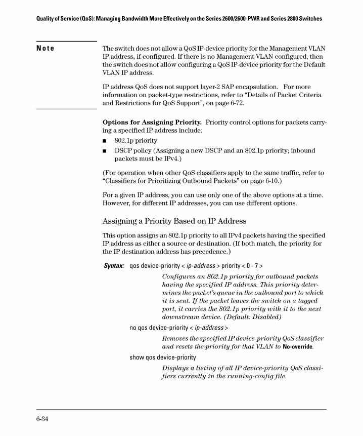
N o t e The switch does not allow a QoS IP-device priority for the Management VLAN IP address, if configured. If there is no Management VLAN configured, then the switch does not allow configuring a QoS IP-device priority for the Default VLAN IP address.
IP address QoS does not support layer-2 SAP encapsulation. For more information on packet-type restrictions, refer to ‘‘Details of Packet Criteria and Restrictions for QoS Support’’, on page 6-72.
Options for Assigning Priority. Priority control options for packets carry-ing a specified IP address include:
■ 802.1p priority
■ DSCP policy (Assigning a new DSCP and an 802.1p priority; inbound packets must be IPv4.)
(For operation when other QoS classifiers apply to the same traffic, refer to “Classifiers for Prioritizing Outbound Packets” on page 6-10.)
For a given IP address, you can use only one of the above options at a time. However, for different IP addresses, you can use different options.
Assigning a Priority Based on IP Address
This option assigns an 802.1p priority to all IPv4 packets having the specified IP address as either a source or destination. (If both match, the priority for the IP destination address has precedence.)
Syntax: qos device-priority < ip-address > priority < 0 - 7 >
Configures an 802.1p priority for outbound packets
having the specified IP address. This priority deter-
mines the packet’s queue in the outbound port to which
it is sent. If the packet leaves the switch on a tagged
port, it carries the 802.1p priority with it to the next
downstream device. (Default: Disabled)
no qos device-priority < ip-address >
Removes the specified IP device-priority QoS classifier
and resets the priority for that VLAN to No-override.
show qos device-priority
Displays a listing of all IP device-priority QoS classi-
fiers currently in the running-config file.
6-34

Quality of Service (QoS): Managing Bandwidth More Effectively on the Series 2600/2600-PWR and Series 2800 SwitchesUsing QoS Classifiers To Configure QoS for Outbound Traffic
For example, configure and list the 802.1p priority for packets carrying the following IP addresses:
Figure 6-13. Example of Configuring and Listing 802.1p Priority Assignments forPackets Carrying Specific IP Addresses
Assigning a DSCP Policy Based on IP Address
This option assigns a previously configured DSCP policy (codepoint and 802.1p priority) to outbound IP packets having the specified IP address (either source or destination). That is, the switch:
1. Selects an incoming IPv4 packet on the basis of the source or destination IP address it carries.
2. Overwrites the packet’s DSCP with the DSCP configured in the switch for such packets, and assigns the 802.1p priority configured in the switch for the new DSCP. (Refer to “Differentiated Services Codepoint (DSCP) Mapping” on page 6-64.)
3. Forwards the packet through the appropriate outbound port queue.
N o t e o n C o m b i n i n g P o l i c y Ty p e s
On the Series 2600/2600-PWR and 2800 switches, “mixing” ToS DSCP policies and 802.1p priorities is not recommended. Refer to the Note on page 6-11.
IP Address 802.1p Priority
10.28.31.1 7
10.28.31.130 5
10.28.31.100 1
10.28.31.101 1
6-35

Quality of Service (QoS): Managing Bandwidth More Effectively on the Series 2600/2600-PWR and Series 2800 Switches
For more on DSCP, refer to “Terminology” on page 6-6.
Steps for Creating a Policy Based on IP Address. This procedure cre-ates a DSCP policy for IPv4 packets carrying the selected IP address (source or destination).
1. Identify the IP address you want to use as a classifier for assigning a DSCP policy.
2. Determine the DSCP policy for packets carrying the selected IP address:
a. Determine the DSCP you want to assign to the selected packets. (This codepoint will be used to overwrite the DSCP carried in packets received from upstream devices.)
b. Determine the 802.1p priority you want to assign to the DSCP.
3. Configure the DSCP policy by using dscp-map to configure the priority to the codepoint you selected in step 2a. (For details, refer to “Differentiated Services Codepoint (DSCP) Mapping” on page 6-64.)
N o t e s A codepoint must have an 802.1p priority assignment (0 - 7) before you can configure a policy for prioritizing packets by IP address. If a codepoint you want to use shows No-override in the Priority column of the DSCP map (show qos dscp-map), then you must assign a 0 - 7 priority before proceeding.
4. Configure the switch to assign the DSCP policy to packets with the specified IP address.
Syntax: qos dscp-map < codepoint > priority < 0 - 7 >
This command is optional if a priority has already been
assigned to the < codepoint >. The command creates a DSCP
policy by assigning an 802.1p priority to a specific DSCP.
When the switch applies this policy to a packet, the priority
determines the packet’s queue in the outbound port to which
it is sent. If the packet leaves the switch on a tagged port, it
carries the 802.1p priority with it to the next downstream
device. If the packet is IPv4, the packet’s DSCP will be
replaced by the codepoint specified in this command.
(Default: For most codepoints, No-override. See figure 6-15 on
page 6-65.)
Syntax: qos device-priority < ip-address > dscp < codepoint >
6-36

Quality of Service (QoS): Managing Bandwidth More Effectively on the Series 2600/2600-PWR and Series 2800 SwitchesUsing QoS Classifiers To Configure QoS for Outbound Traffic
For example, suppose you wanted to assign these DSCP policies to the packets identified by the indicated IP addresses:
1. Determine whether the DSCPs already have priority assignments, which could indicate use by existing applications. This is not a problem if the configured priorities are acceptable for all applications using the same DSCP. (Refer to the “Note On Changing a Priority Setting” on page 6-67. Also, a DSCP must have a priority configured before you can assign any QoS classifiers to use it.)
Figure 6-14. Display the Current DSCP-Map Configuration
Assigns a DSCP policy to packets carrying the specified IP
address, and overwrites the DSCP in these packets with the
assigned < codepoint > value. This policy includes an 802.1p
priority and determines the packet’s queue in the outbound
port to which it is sent. If the packet leaves the switch on a
tagged port, it carries the 802.1p priority with it to the next
downstream device. (Default: No-override)
no qos device-priority < ip-address >
Deletes the specified IP address as a QoS classifier.
show qos device-priority
Displays a listing of all QoS Device Priority classifiers
currently in the running-config file.
IP Address DSCP Policies
DSCP Priority
10.28.31.1 000111 7
10.28.31.130 000101 5
10.28.31.100 000010 1
10.28.31.101 000010 1
The DSCPs for this example have not yet been assigned an 802.1p priority level.
6-37
Quality of Service (QoS): Managing Bandwidth More Effectively on the Series 2600/2600-PWR and Series 2800 Switches
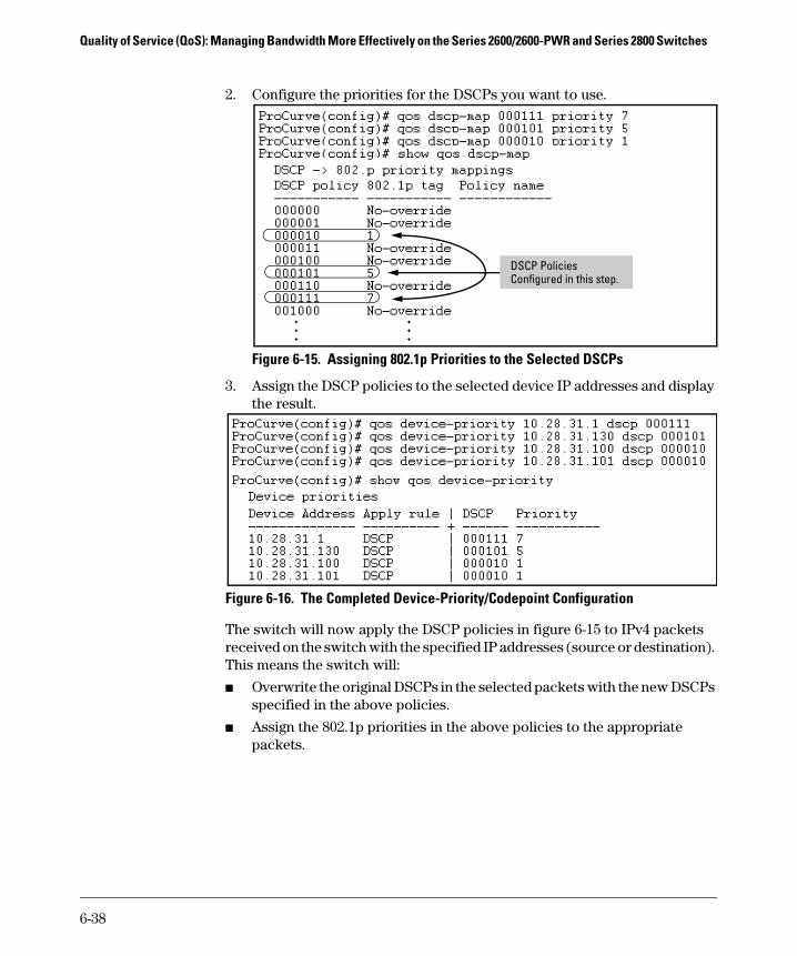
2. Configure the priorities for the DSCPs you want to use.
Figure 6-15. Assigning 802.1p Priorities to the Selected DSCPs
3. Assign the DSCP policies to the selected device IP addresses and display the result.
Figure 6-16. The Completed Device-Priority/Codepoint Configuration
The switch will now apply the DSCP policies in figure 6-15 to IPv4 packets received on the switch with the specified IP addresses (source or destination). This means the switch will:
■ Overwrite the original DSCPs in the selected packets with the new DSCPs specified in the above policies.
■ Assign the 802.1p priorities in the above policies to the appropriate packets.
DSCP Policies Configured in this step.
6-38

Quality of Service (QoS): Managing Bandwidth More Effectively on the Series 2600/2600-PWR and Series 2800 SwitchesUsing QoS Classifiers To Configure QoS for Outbound Traffic
QoS IP Type-of-Service (ToS) Policy and Priority
QoS Classifier Precedence: 3
This feature applies only to IPv4 traffic and performs either of the following:
■ ToS IP-Precedence Mode: All IP packets generated by upstream devices and applications include precedence bits in the ToS byte. Using this mode, the switch uses these bits to compute and assign the corresponding 802.1p priority.
■ ToS Differentiated Services (Diffserv) Mode: This mode requires knowledge of the codepoints set in IP packets by the upstream devices and applications. It uses the ToS codepoint in IP packets coming from upstream devices and applications to assign 802.1p priorities to the pack-ets. You can use this option to do both of the following:
• Assign a New Prioritization Policy: A “policy” includes both a codepoint and a corresponding 802.1p priority. This option selects an incoming IPv4 packet on the basis of its codepoint and assigns a new codepoint and corresponding 802.1p priority. (Use the qos dscp-map command to specify a priority for any codepoint—page 6-64.)
• Assign an 802.1p Priority: This option reads the DSCP of an incoming IPv4 packet and, without changing this codepoint, assigns the 802.1p priority to the packet, as configured in the DSCP Policy Table (page 6-64). This means that a priority value of 0 - 7 must be configured for a DSCP before the switch will attempt to perform a QoS match on the packet’s DSCP bits.
Before configuring the ToS Diffserv mode, you must use the dscp-map command to configure the desired 802.1p priorities for the codepoints you want to use for either option. This command is illustrated in the following examples and is described under “Differentiated Services Codepoint (DSCP) Mapping” on page 6-64.
Unless IP-Precedence mode and Diffserv mode are both disabled (the default setting), enabling one automatically disables the other. For more on ToS
operation, refer to “Details of QoS IP Type-of-Service” on page 6-49.
N o t e s On the Series 2600/2600-PWR and 2800 switches, “mixing” ToS DSCP policies and 802.1p priorities is not recommended. Refer to the Note on page 6-11.
IP-ToS QoS does not support layer-2 SAP encapsulation. or more information on packet-type restrictions, refer to ‘‘Details of Packet Criteria and Restrictions for QoS Support’’, on page 6-72.
6-39

Quality of Service (QoS): Managing Bandwidth More Effectively on the Series 2600/2600-PWR and Series 2800 Switches
Assigning an 802.1p Priority to IPv4 Packets on the Basis of the ToS Precedence Bits
If a device or application upstream of the switch sets the precedence bits in the ToS byte of IPv4 packets, you can use this feature to apply that setting for prioritizing packets for outbound port queues. If the outbound packets are in a tagged VLAN, this priority is carried as an 802.1p value to the adjacent downstream devices.
With this option, prioritization of outbound packets relies on the IP-Prece-dence bit setting that IP packets carry with them from upstream devices and applications. To configure and verify this option:
Figure 6-17. Example of Enabling ToS IP-Precedence Prioritization
Syntax: qos type-of-service ip-precedence
Causes the switch to automatically assign an 802.1p prior-
ity to all IPv4 packets by computing each packet’s 802.1p
priority from the precedence bits the packet carries. This
priority determines the packet’s queue in the outbound port
to which it is sent. If the packet leaves the switch on a tagged
port, it carries the 802.1p priority with it to the next
downstream device. (ToS IP Precedence Default: Disabled)
no qos type-of-service
Disables all ToS classifier operation, including prioritiza-
tion using the precedence bits.
show qos type-of-service
When ip-precedence is enabled (or if neither ToS option is
configured), shows the ToS configuration status. If diff-
services is enabled, lists codepoint data as described under
“Assigning a DSCP Policy on the Basis of the DSCP in IPv4
Packets Received from Upstream Devices” on page 6-45.
Default ToS Configuration Current ToS Configuration
6-40

Quality of Service (QoS): Managing Bandwidth More Effectively on the Series 2600/2600-PWR and Series 2800 SwitchesUsing QoS Classifiers To Configure QoS for Outbound Traffic
To replace this option with the ToS diff-services option, just configure diff-services as described below, which automatically disables IP-Precedence. To disable IP-Precedence without enabling the diff-services option, use this command:
ProCurve(config)# no qos type-of-service
Assigning an 802.1p Priority to IPv4 Packets on the Basis of Incoming DSCP
One of the best uses for this option is on an interior switch where you want to honor (continue) a policy set on an edge switch. That is, it enables you to select incoming packets having a specific DSCP and forward these packets with the desired 802.1p priority. For example, if an edge switch “A” marks all packets received on port A5 with a particular DSCP, you can configure a downstream (interior) switch “B” to handle such packets with the desired priority (regardless of whether 802.1Q tagged VLANs are in use).
Figure 6-18. Interior Switch “B” Honors the Policy Established in Edge Switch “A”
To do so, assign the desired 802.1p priority to the same codepoint that the upstream or edge switch assigns to the selected packets. When the down-stream switch receives an IPv4 packet carrying one of these codepoints, it assigns the configured priority to the packet and sends it out the appropriate priority queue. (The packet retains the codepoint it received from the upstream or edge switch). You can use this option concurrently with the diffserv DSCP Policy option (described later in this section), as long as the DSCPs specified in the two options do not match.
LAN
A5
EdgeSwitch
“A”
LAN
InteriorSwitch
“B”Work-Group
Work-Group
Marked Traffic from port A5 on Edge Switch “A”Other Traffic
6-41

Quality of Service (QoS): Managing Bandwidth More Effectively on the Series 2600/2600-PWR and Series 2800 Switches
Note on DSCP Use Different applications may use the same DSCP in their IP packets. Also, the same application may use multiple DSCPs if the application originates on different clients, servers, or other devices. Using an edge switch enables you to select the packets you want and mark them with predictable DSCPs that can be used by downstream switches to honor policies set in the edge switch.
When enabled, the switch applies direct 802.1p prioritization to all packets having codepoints that meet these criteria:
■ The codepoint is configured with an 802.1p priority in the DSCP table. (Codepoints configured with No-override are not used.)
■ The codepoint is not configured for a new DSCP policy assignment.
Thus, the switch does not allow the same incoming codepoint (DSCP) to be used simultaneously for directly assigning an 802.1p priority and also assign-ing a DSCP policy. For a given incoming codepoint, if you configure one option and then the other, the second overwrites the first.
To use this option:
1. Identify a DSCP used to set a policy in packets received from an upstream or edge switch.
2. Determine the 802.1p priority (0 - 7) you want to apply to packets carrying the identified DSCP. (You can either maintain the priority assigned in the upstream or edge switch, or assign a new priority.)
3. Use qos dscp-map < codepoint > priority < 0 - 7 > to assign the 802.1p priority you want to the specified DSCP. (For more on this topic, refer to “Differ-entiated Services Codepoint (DSCP) Mapping” on page 6-64.)
4. Enable diff-services
6-42

Quality of Service (QoS): Managing Bandwidth More Effectively on the Series 2600/2600-PWR and Series 2800 SwitchesUsing QoS Classifiers To Configure QoS for Outbound Traffic
.
For example, an edge switch “A” in an untagged VLAN assigns a DSCP of 000110 on IP packets it receives on port A6, and handles the packets with high priority (7). When these packets reach interior switch “B” you want the switch to handle them with the same high priority. To enable this operation you would
Syntax: qos type-of-service diff-services < codepoint >
Causes the switch to read the < codepoint > (DSCP) of an
incoming IPv4 packet and, when a match occurs, assign a
corresponding 802.1p priority, as configured in the switch’s
DSCP table (page 6-65).
no qos type-of-service
Disables all ToS classifier operation.
no qos dscp-map < codepoint >
Disables direct 802.1p priority assignment to packets carry-
ing the < codepoint > by reconfiguring the codepoint priority
assignment in the DSCP table to No-override. Note that if this
codepoint is in use as a DSCP policy for another diffserv
codepoint, you must disable or redirect the other diffserv
codepoint’s DSCP policy before you can disable or change the
codepoint. For example, in figure 6-19 you cannot change
the priority for the 000000 codepoint until you redirect the
DSCP policy for 000001 away from using 000000 as a policy.
(Refer to “Note On Changing a Priority Setting” on page 6-67.
Refer also to “Differentiated Services Codepoint (DSCP)
Mapping” on page 6-64.)
show qos type-of-service
Displays current Type-of-Service configuration. In diffserv
mode it also shows the current direct 802.1p assignments
and the current DSCP assignments covered later in this
section.
6-43

Quality of Service (QoS): Managing Bandwidth More Effectively on the Series 2600/2600-PWR and Series 2800 Switches
configure an 802.1p priority of 7 for packets received with a DSCP of 000110, and then enable diff-services:
Figure 6-19. Example Showing Codepoints Available for Direct 802.1p Priority Assignments
Figure 6-20. Example of a Type-of-Service Configuration Enabling Both Direct 802.1p Priority Assignment and DSCP Policy Assignment
Executing this command displays the current ToS configuration and shows that the selected DSCP is not currently in use.
The 000110 codepoint is unused, and thus available for directly assigning an 802.1p priority without changing the packet’s DSCP.
Note: All codepoints without a “DSCP Policy” entry are available for direct 802.1p priority assignment.
Notice that codepoints 000000 and 001001 are named as DSCP policies by other codepoints (000001 and 000110 respectively). This means they are not available for changing to a different 802.1p priority.
Outbound IP packets with a DSCP of 000110 will have a priority of 7.
6-44

Quality of Service (QoS): Managing Bandwidth More Effectively on the Series 2600/2600-PWR and Series 2800 SwitchesUsing QoS Classifiers To Configure QoS for Outbound Traffic
Assigning a DSCP Policy on the Basis of the DSCP in IPv4 Packets Received from Upstream Devices
The preceding section describes how to forward a policy set by an edge (or upstream) switch. This option changes a DSCP policy in an IPv4 packet by changing its IP ToS codepoint and applying the priority associated with the new codepoint. (A DSCP policy consists of a differentiated services codepoint and an associated 802.1p priority.) You can use this option concurrently with the diffserv 802.1p priority option (above), as long as the DSCPs specified in the two options do not match.
To use this option to configure a change in policy:
1. Identify a DSCP used to set a policy in packets received from an upstream or edge switch.
2. Create a new policy by using qos dscp-map < codepoint > priority < 0 - 7 > to configure an 802.1p priority for the codepoint you will use to overwrite the DSCP the packet carries from upstream. (For more on this topic, refer to “Differentiated Services Codepoint (DSCP) Mapping” on page 6-64.)
3. Use qos type-of-service diff-services < incoming-DSCP > dscp < outgoing-DSCP > to change the policy on packets coming from the edge or upstream switch with the specified incoming DSCP.
(Figure 6-18 on page 6-41 illustrates this scenario.)
N o t e s On the Series 2600/2600-PWR and 2800 switches, “mixing” ToS DSCP policies and 802.1p priorities is not recommended. Refer to the Note on page 6-11.
Syntax: qos type-of-service diff-services
Enables ToS diff-services.
qos type-of-service diff-services < current-codepoint > dscp < new-codepoint >
Configures the switch to select an incoming IP packet carry-
ing the <current-codepoint > and then use the <new-codepoint> to assign a new, previously configured DSCP policy to the
packet. The policy overwrites the <current-codepoint> with the
< new-codepoint > and assigns the 802.1p priority specified
by the policy. (Use the qos dscp-map command to define the
priority for the DSCPs—page 6-64.)
6-45

Quality of Service (QoS): Managing Bandwidth More Effectively on the Series 2600/2600-PWR and Series 2800 Switches
For example, suppose you want to configure the following two DSCP policies for packets received with the indicated DSCPs.
1. Determine whether the DSCPs already have priority assignments, which could indicate use by existing applications. This is not a problem as long as the configured priorities are acceptable for all applications using the same DSCP. (Refer to the “Note On Changing a Priority Setting” on page 6-67. Also, a DSCP must have a priority configured before you can assign any QoS classifiers to use it.)
no qos type-of-service
Disables all ToS classifier operation. Current ToS DSCP
policies and priorities remain in the configuration and will
become available if you re-enable ToS diff-services.
no qos type-of-service [diff-services < codepoint >]
Deletes the DSCP policy assigned to the
< codepoint > and returns the < codepoint > to the 802.1p
priority setting it had before the DSCP policy was assigned.
(This will be either a value from 0 - 7 or No-override.)
show qos type-of-service
Displays a listing of codepoints, with any corresponding
DSCP policy re-assignments for outbound packets. Also lists
the (802.1p) priority for each codepoint that does not have a
DSCP policy assigned to it.
Received DSCP
Policy DSCP
802.1p Priority
Policy Name(Optional)
001100 000010 6 Level 6
001101 000101 4 Level 4
6-46

Quality of Service (QoS): Managing Bandwidth More Effectively on the Series 2600/2600-PWR and Series 2800 SwitchesUsing QoS Classifiers To Configure QoS for Outbound Traffic
Figure 6-21. Display the Current DSCP-Map Configuration
2. Configure the policies in the DSCP table:
Figure 6-22. Example of Policies Configured (with Optional Names) in the DSCP Table
The DSCPs for this example have not yet been assigned an 802.1p priority level.
6-47
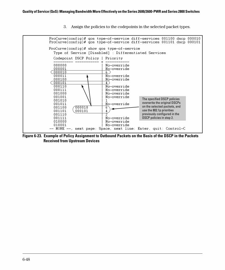
Quality of Service (QoS): Managing Bandwidth More Effectively on the Series 2600/2600-PWR and Series 2800 Switches
3. Assign the policies to the codepoints in the selected packet types.
Figure 6-23. Example of Policy Assignment to Outbound Packets on the Basis of the DSCP in the Packets Received from Upstream Devices
The specified DSCP policies overwrite the original DSCPs on the selected packets, and use the 802.1p priorities previously configured in the DSCP policies in step 2.
6-48
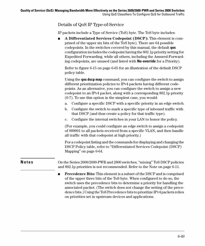
Quality of Service (QoS): Managing Bandwidth More Effectively on the Series 2600/2600-PWR and Series 2800 SwitchesUsing QoS Classifiers To Configure QoS for Outbound Traffic
Details of QoS IP Type-of-Service
IP packets include a Type of Service (ToS) byte. The ToS byte includes:
■ A Differentiated Services Codepoint (DSCP): This element is com-prised of the upper six bits of the ToS byte). There are 64 possible codepoints. In the switches covered by this manual, the default qos configuration includes the codepoint having the 802.1p priority setting for Expedited Forwarding, while all others, including the Assured-Forward-ing codepoints, are unused (and listed with No-override for a Priority).
Refer to figure 6-15 on page 6-65 for an illustration of the default DSCP policy table.
Using the qos dscp map command, you can configure the switch to assign different prioritization policies to IPv4 packets having different code-points. As an alternative, you can configure the switch to assign a new codepoint to an IPv4 packet, along with a corresponding 802.1p priority (0-7). To use this option in the simplest case, you would:
a. Configure a specific DSCP with a specific priority in an edge switch.
b. Configure the switch to mark a specific type of inbound traffic with that DSCP (and thus create a policy for that traffic type).
c. Configure the internal switches in your LAN to honor the policy.
(For example, you could configure an edge switch to assign a codepoint of 000001 to all packets received from a specific VLAN, and then handle all traffic with that codepoint at high priority.)
For a codepoint listing and the commands for displaying and changing the DSCP Policy table, refer to “Differentiated Services Codepoint (DSCP) Mapping” on page 6-64.
N o t e s On the Series 2600/2600-PWR and 2800 switches, “mixing” ToS DSCP policies and 802.1p priorities is not recommended. Refer to the Note on page 6-11.
■ Precedence Bits: This element is a subset of the DSCP and is comprised of the upper three bits of the ToS byte. When configured to do so, the switch uses the precedence bits to determine a priority for handling the associated packet. (The switch does not change the setting of the prece-dence bits.) Using the ToS Precedence bits to prioritize IPv4 packets relies on priorities set in upstream devices and applications.
6-49

Quality of Service (QoS): Managing Bandwidth More Effectively on the Series 2600/2600-PWR and Series 2800 Switches
Figure 6-24 shows an example of the ToS byte in the header for an IPv4 packet, and illustrates the diffserv bits and precedence bits in the ToS byte. (Note that the Precedence bits are a subset of the Differentiated Services bits.)
Figure 6-24. The ToS Codepoint and Precedence Bits
Field: Destination MAC Address
Source MAC Address
802.1Q Field Type & Version
ToS Byte …
Packet: FF FF FF FF FF FF 08 00 09 00 00 16 08 00 45 E 0 ...
Differentiated Services Codepoint
Rsvd.Precedence Bits
1 1 1 0 0 0 0 0
E 0
6-50

Quality of Service (QoS): Managing Bandwidth More Effectively on the Series 2600/2600-PWR and Series 2800 SwitchesUsing QoS Classifiers To Configure QoS for Outbound Traffic
Table 6-13. How the Switch Uses the ToS Configuration
Table 6-14. ToS IP-Precedence Bit Mappings to 802.1p Priorities
Outbound Port ToS Option: IP Precedence (Value = 0 - 7)
Differentiated Services
IP Packet Sent Out an Untagged Port in a VLAN
Depending on the value of the IP Precedence bits in the packet’s ToS field, the packet will go to one of four outbound port queues in the switch:
1 - 2 = low priority0 - 3 = normal priority4 - 5 = high priority6 - 7 = high priority
For a given packet carrying a ToS codepoint that the switch has been configured to detect:• Change the codepoint according to the configured policy and
assign the 802.1p priority specified for the new codepoint in the DSCP Policy Table (page 6-64).
• Do not change the codepoint, but assign the 802.1p priority specified for the existing codepoint in the DSCP Policy Table (page 6-64).
Depending on the 802.1p priority used, the packet will leave the switch through one of the following queues:
1 - 2 = low priority0 - 3 = normal priority4 - 5 = high priority6 - 7 = high priority
If No-override (the default) has been configured for a specified codepoint, then the packet is not prioritized by ToS and, by default, is sent to the “normal priority” queue.
IP Packet Sent Out an Untagged Port in a VLAN
Same as above, plus the IP Prece-dence value (0 - 7) will be used to set a corresponding 802.1p priority in the VLAN tag carried by the packet to the next downstream device. Refer to table 6-14, below.
Same as above, plus the Priority value (0 - 7) will be used to set a corresponding 802.1p priority in the VLAN tag carried by the packet to the next downstream device. Where No-override is the assigned priority, the VLAN tag carries a “0” (normal priority) 802.1p setting if not prioritized by other QoS classifiers.
ToS Byte IP Precedence Bits
Corresponding 802.1p Priority
Service Priority Level
000 1 Lowest
001 2 Low
002 0 Normal
003 3
004 4
005 5
006 6
007 7 Highest
6-51

Quality of Service (QoS): Managing Bandwidth More Effectively on the Series 2600/2600-PWR and Series 2800 Switches
QoS VLAN-ID (VID) Priority
QoS Classifier Precedence: 5
The QoS VLAN-ID option supports up to 120 VLAN IDs (VIDs) as QoS classi-fiers, depending on rule use by other QoS options.
Where a particular VLAN-ID classifier has the highest precedence in the switch for traffic in that VLAN, then traffic received in that VLAN is marked with the VID classifier’s configured priority level. Different VLAN-ID classifiers can have differing priority levels.
Options for Assigning Priority. Priority control options for packets carry-ing a specified VLAN-ID include:
■ 802.1p priority
■ DSCP policy (Assigning a new DSCP and an associated 802.1p priority; inbound packets must be IPv4.)
(For operation when other QoS classifiers apply to the same traffic, refer to “Classifiers for Prioritizing Outbound Packets” on page 6-10.)
N o t e QoS with VID priority applies to static VLANs only, and applying QoS to dynamic VLANs created by GVRP operation is not supported. A VLAN must exist while a subject of a QoS configuration, and eliminating a VLAN from the switch causes the switch to clear any QoS features configured for that VID.
Assigning a Priority Based on VLAN-ID
This option assigns a priority to all outbound packets having the specified VLAN-ID (VID). You can configure this option by either specifying the VLAN-ID ahead of the qos command or moving to the VLAN context for the VLAN you want to configure for priority.
6-52

Quality of Service (QoS): Managing Bandwidth More Effectively on the Series 2600/2600-PWR and Series 2800 SwitchesUsing QoS Classifiers To Configure QoS for Outbound Traffic
1. For example, suppose that you have the following VLANs configured on the switch and want to prioritize them as shown:
Figure 6-25. Example of a List of VLANs Available for QoS Prioritization
Syntax: vlan < vid > qos priority < 0 - 7 >
Configures an 802.1p priority for outbound packets belong-
ing to the specified VLAN. This priority determines the
packet’s queue in the outbound port to which it is sent. If the
packet leaves the switch on a tagged port, it carries the 802.1p
priority with it to the next downstream device. You can
configure one QoS classifier for each VLAN-ID. (Default: No-override)
no vlan < vid > qos
Removes the specified VLAN-ID as a QoS classifier and resets
the priority for that VLAN to No- override.
show qos vlan-priority
Displays a listing of the QoS VLAN-ID classifiers currently
in the running-config file, with their priority data.
Set Priority To 7
Set Priority To 2
Set Priority To 5
6-53
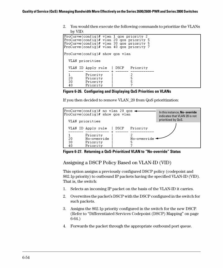
Quality of Service (QoS): Managing Bandwidth More Effectively on the Series 2600/2600-PWR and Series 2800 Switches
2. You would then execute the following commands to prioritize the VLANs by VID:
Figure 6-26. Configuring and Displaying QoS Priorities on VLANs
If you then decided to remove VLAN_20 from QoS prioritization:
Figure 6-27. Returning a QoS-Prioritized VLAN to “No-override” Status
Assigning a DSCP Policy Based on VLAN-ID (VID)
This option assigns a previously configured DSCP policy (codepoint and 802.1p priority) to outbound IP packets having the specified VLAN-ID (VID). That is, the switch:
1. Selects an incoming IP packet on the basis of the VLAN-ID it carries.
2. Overwrites the packet’s DSCP with the DSCP configured in the switch for such packets.
3. Assigns the 802.1p priority configured in the switch for the new DSCP. (Refer to “Differentiated Services Codepoint (DSCP) Mapping” on page 6-64.)
4. Forwards the packet through the appropriate outbound port queue.
In this instance, No- override indicates that VLAN 20 is not prioritized by QoS.
6-54

Quality of Service (QoS): Managing Bandwidth More Effectively on the Series 2600/2600-PWR and Series 2800 SwitchesUsing QoS Classifiers To Configure QoS for Outbound Traffic
N o t e On the Series 2600/2600-PWR and 2800 switches, “mixing” ToS DSCP policies and 802.1p priorities is not recommended. Refer to the Note on page 6-11.
For more on DSCP, refer to “Terminology” on page 6-6.
Steps for Creating a Policy Based on VLAN-ID Classifier.
1. Determine the VLAN-ID classifier to which you want to assign a DSCP policy.
2. Determine the DSCP policy for packets carrying the selected VLAN-ID:
a. Determine the DSCP you want to assign to the selected packets. (This codepoint will be used to overwrite the DSCP carried in packets received from upstream devices.)
b. Determine the 802.1p priority you want to assign to the DSCP.
3. Configure the DSCP policy by using qos dscp-map to configure the priority for each codepoint. (For details, see the example later in this section, and to “Differentiated Services Codepoint (DSCP) Mapping” on page 6-64.)
N o t e A codepoint must have an 802.1p priority (0 - 7) before you can configure the codepoint for use in prioritizing packets by VLAN-ID. If a codepoint you want to use shows No-override in the Priority column of the DSCP Policy table (show qos dscp-map), then assign a priority before proceeding.
4. Configure the switch to assign the DSCP policy to packets with the specified VLAN-ID.
Syntax: qos dscp-map < codepoint > priority < 0 - 7 >
This command is optional if a priority has already been
assigned to the < codepoint >. The command creates a DSCP
policy by assigning an 802.1p priority to a specific DSCP.
When the switch applies this priority to a packet, the priority
determines the packet’s queue in the outbound port to which
it is sent. If the packet leaves the switch on a tagged port, it
carries the 802.1p priority with it to the next downstream
device. If the packet is IPv4, the packet’s DSCP will be
replaced by the codepoint specified in this command.
(Default: For most codepoints, No-override. See figure 6-15 on
page 6-65 on page 6-65.)
6-55

Quality of Service (QoS): Managing Bandwidth More Effectively on the Series 2600/2600-PWR and Series 2800 Switches
For example, suppose you wanted to assign this set of priorities:
1. Determine whether the DSCPs already have priority assignments, which could indicate use by existing applications. This is not a problem as long as the configured priorities are acceptable for all applications using the same DSCP. (Refer to the “Note On Changing a Priority Setting” on page 6-67. Also, a DSCP must have a priority configured before you can assign any QoS classifiers to use it.)
Figure 6-28. Display the Current Configuration in the DSCP Policy Table
Syntax: vlan < vid > qos dscp < codepoint >
Assigns a DSCP policy to packets carrying the specified IP
address, and overwrites the DSCP in these packets with the
assigned < codepoint > value. This policy includes an 802.1p
priority and determines the packet’s queue in the outbound
port to which it is sent. If the packet leaves the switch on a
tagged port, it carries the 802.1p priority with it to the next
downstream device. (Default: No-override)
no vlan < vid > qos
Removes QoS classifier for the specified VLAN.
show qos device-priority
Displays a listing of all QoS VLAN-ID classifiers currently
in the running-config file.
VLAN-ID DSCP Priority
40 000111 7
30 000101 5
20 000010 1
1 000010 1
The DSCPs for this example have not yet been assigned an 802.1p priority level.
6-56

Quality of Service (QoS): Managing Bandwidth More Effectively on the Series 2600/2600-PWR and Series 2800 SwitchesUsing QoS Classifiers To Configure QoS for Outbound Traffic
2. Configure the priorities for the DSCPs you want to use.
Figure 6-29. Assign Priorities to the Selected DSCPs
3. Assign the DSCP policies to the selected VIDs and display the result.
Figure 6-30. The Completed VID-DSCP Priority Configuration
The switch will now apply the DSCP policies in figure 6-30 to packets received on the switch with the specified VLAN-IDs. This means the switch will:
■ Overwrite the original DSCPs in the selected packets with the new DSCPs specified in the above policies.
■ Assign the 802.1p priorities in the above policies to the appropriate packets.
Priorities Configured in this step.
6-57

Quality of Service (QoS): Managing Bandwidth More Effectively on the Series 2600/2600-PWR and Series 2800 Switches
QoS Source-Port Priority
For information on configuring port-based priority for the 4100gl and 6108 switches, refer to the Management and Configuration Guide.
QoS Classifier Precedence: 6
The QoS source-port option enables you to use a packet’s source-port on the switch as a QoS classifier. Where a particular source-port classifier has the highest precedence in the switch for traffic entering through that port, then traffic received from the port is marked with the source-port classifier’s configured priority level. Different source-port classifiers can have different priority levels.
Options for Assigning Priority. Priority control options for packets from a specified source-port include:
■ 802.1p priority
■ DSCP policy (Assigning a new DSCP and an associated 802.1p priority; inbound packets must be IPv4.)
(For operation when other QoS classifiers apply to the same traffic, refer to “Classifiers for Prioritizing Outbound Packets” on page 6-10.)
Assigning a Priority Based on Source-Port
This option assigns a priority to outbound packets having the specified source-port. Configure this option by either specifying the source-port ahead of the qos command or moving to the port context for the port you want to configure for priority. (For configuring multiple source-ports with the same priority, you may find it easier to use the interface < port-list > command to go to the port context instead of individually configuring the priority for each port.)
Syntax: interface < port-list > qos priority < 0 - 7 >Configures an 802.1p priority for packets entering the switch
through the specified (source) ports. This priority determines
the packet queue in the outbound port(s) to which traffic is
sent. If a packet leaves the switch on a tagged port, it carries
the 802.1p priority with it to the next downstream device. You
can configure one QoS classifier for each source-port or group
of source-ports. (Default: No-override)
no interface < port-list > qos Disables use of the specified source-port(s) for QoS classi-
fier(s) and resets the priority for the specified source-port(s)
to No-override.
show qos port-priorityLists the QoS port-priority classifiers with their priority data.
6-58

Quality of Service (QoS): Managing Bandwidth More Effectively on the Series 2600/2600-PWR and Series 2800 SwitchesUsing QoS Classifiers To Configure QoS for Outbound Traffic
For example, suppose that you want to prioritize inbound traffic on the following source-ports:
You would then execute the following commands to prioritize traffic received on the above ports:
Figure 6-31. Configuring and Displaying Source-Port QoS Priorities
If you then decided to remove port 1 from QoS prioritization:
Figure 6-32. Returning a QoS-Prioritized VLAN to “No-override” Status
Source-Port Priority
1 - 3 2
4 3
5, 8 5
9 - 11 6
In this instance, No-override indicates that port A1 is not prioritized by QoS.
6-59

Quality of Service (QoS): Managing Bandwidth More Effectively on the Series 2600/2600-PWR and Series 2800 Switches
Assigning a DSCP Policy Based on the Source-Port
This option assigns a previously configured DSCP policy (codepoint and 802.1p priority) to outbound IP packets (received from the specified source-ports). That is, the switch:
1. Selects an incoming IP packet on the basis of its source-port on the switch.
2. Overwrites the packet’s DSCP with the DSCP configured in the switch for such packets.
3. Assigns the 802.1p priority configured in the switch for the new DSCP. (Refer to “Differentiated Services Codepoint (DSCP) Mapping” on page 6-64.)
4. Forwards the packet through the appropriate outbound port queue.
N o t e On the Series 2600/2600-PWR and 2800 switches, “mixing” ToS DSCP policies and 802.1p priorities is not recommended. Refer to the Note on page 6-11.
For more on DSCP, refer to “Terminology” on page 6-6.
Steps for Creating a Policy Based on Source-Port Classifiers.
N o t e You can select one DSCP per source-port. Also, configuring a new DSCP for a source-port automatically overwrites (replaces) any previous DSCP or 802.1p priority configuration for that port.)
1. Identify the source-port classifier to which you want to assign a DSCP policy.
2. Determine the DSCP policy for packets having the selected source-port:
a. Determine the DSCP you want to assign to the selected packets. (This codepoint will be used to overwrite the DSCP carried in packets received through the source-port from upstream devices.)
b. Determine the 802.1p priority you want to assign to the DSCP.
3. Configure the DSCP policy by using qos dscp-map to configure the priority for each codepoint. (For details, refer to the example later in this section and to “Differentiated Services Codepoint (DSCP) Mapping” on page 6-64.)
6-60

Quality of Service (QoS): Managing Bandwidth More Effectively on the Series 2600/2600-PWR and Series 2800 SwitchesUsing QoS Classifiers To Configure QoS for Outbound Traffic
N o t e A codepoint must have an 802.1p priority assignment (0 - 7) before you can configure that codepoint as a criteria for prioritizing packets by source-port. If a codepoint shows No-override in the Priority column of the DSCP Policy Table (show qos dscp-map), then you must assign a 0 - 7 priority before proceeding.
4. Configure the switch to assign the DSCP policy to packets from the specified source-port.
Syntax: qos dscp-map < codepoint > priority < 0 - 7 >
This command is optional if a priority has already
been assigned to the < codepoint >. The command creates
a DSCP policy by assigning an 802.1p priority to a
specific DSCP. When the switch applies this priority to
a packet, the priority determines the packet’s queue in
the outbound port to which it is sent. If the packet leaves
the switch on a tagged port, it carries the 802.1p
priority with it to the next downstream device.
(Default: For most codepoints, No-override. See figure 6-
15 on page 6-65 on page 6-65.)
Syntax: interface < port-list > qos dscp < codepoint >
Assigns a DSCP policy to packets from the specified
source-port(s), and overwrites the DSCP in these pack-
ets with the assigned < codepoint > value. This policy
includes an 802.1p priority and determines the
packet’s queue in the outbound port to which it is sent.
If the packet leaves the switch on a tagged port, it
carries the 802.1p priority with it to the next down-
stream device. (Default: No-override)
no interface [e] < port-list > qos
Removes QoS classifier for the specified source-port(s).
show qos source-port
Displays a listing of all source-port QoS classifiers
currently in the running-config file.
6-61
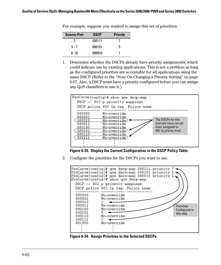
Quality of Service (QoS): Managing Bandwidth More Effectively on the Series 2600/2600-PWR and Series 2800 Switches
For example, suppose you wanted to assign this set of priorities:
1. Determine whether the DSCPs already have priority assignments, which could indicate use by existing applications. This is not a problem as long as the configured priorities are acceptable for all applications using the same DSCP. (Refer to the “Note On Changing a Priority Setting” on page 6-67. Also, a DSCP must have a priority configured before you can assign any QoS classifiers to use it.)
Figure 6-33. Display the Current Configuration in the DSCP Policy Table
2. Configure the priorities for the DSCPs you want to use.
Figure 6-34. Assign Priorities to the Selected DSCPs
Source-Port DSCP Priority
2 000111 7
5 - 7 000101 5
8, 10 000010 1
The DSCPs for this example have not yet been assigned an 802.1p priority level.
Priorities Configured in this step.
6-62

Quality of Service (QoS): Managing Bandwidth More Effectively on the Series 2600/2600-PWR and Series 2800 SwitchesUsing QoS Classifiers To Configure QoS for Outbound Traffic
3. Assign the DSCP policies to the selected source-ports and display the result.
Figure 6-35. The Completed Source-Port DSCP-Priority Configuration
6-63

Quality of Service (QoS): Managing Bandwidth More Effectively on the Series 2600/2600-PWR and Series 2800 Switches
Differentiated Services Codepoint (DSCP) Mapping
The DSCP Policy Table associates an 802.1p priority with a specific ToS byte codepoint in an IPv4 packet. This enables you to set a LAN policy that operates independently of 802.1Q VLAN-tagging.
In the default state, most of the 64 codepoints do not assign an 802.1p priority, as indicated by No-override in table 6-15 on page 6-65.
You can list the current DSCP Policy table, change the codepoint priority assignments, and assign optional names to the codepoints.
Syntax: show qos dscp-map
Displays the DSCP Policy Table.
qos dscp-map < codepoint > priority < 0 - 7 > [name < ascii-string >]
Configures an 802.1p priority for the specified codepoint
and, optionally, an identifying (policy) name.
no qos dscp-map < codepoint >
Reconfigures the 802.1p priority for <codepoint> to No-over-ride. Also deletes the codepoint policy name, if configured.
no qos dscp-map < codepoint > name
Deletes only the policy name, if configured, for < codepoint >.
6-64
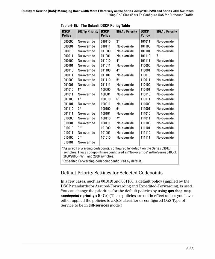
Quality of Service (QoS): Managing Bandwidth More Effectively on the Series 2600/2600-PWR and Series 2800 SwitchesUsing QoS Classifiers To Configure QoS for Outbound Traffic
Table 6-15. The Default DSCP Policy Table
Default Priority Settings for Selected Codepoints
In a few cases, such as 001010 and 001100, a default policy (implied by the DSCP standards for Assured-Forwarding and Expedited-Forwarding) is used. You can change the priorities for the default policies by using qos dscp-map <codepoint > priority < 0 - 7 >).(These policies are not in effect unless you have either applied the policies to a QoS classifier or configured QoS Type-of-Service to be in diff-services mode.)
DSCPPolicy
802.1p Priority DSCPPolicy
802.1p Priority DSCPPolicy
802.1p Priority
000000000001000010000011000100000101000110000111001000001001001010001011001100001101001110001111010000010001010010010011010100010101
No-overrideNo-overrideNo-overrideNo-overrideNo-overrideNo-overrideNo-overrideNo-overrideNo-overrideNo-override1*No-override1*No-override2*No-overrideNo-overrideNo-override0 *No-override0 *No-override
010110010111011000011001011010011011011100011101011110011111100000100001100010100011100100100101100110100111101000101001101010
3*No-overrideNo-overrideNo-override4*No-override4*No-override5*No-overrideNo-overrideNo-override6*No-override6*No-override7*No-overrideNo-overrideNo-overrideNo-override
101011101100101101101110101111110000110001110010110011110100110101110110110111111000111001111010111011111100111101111110111111
No-overrideNo-overrideNo-override7+
No-overrideNo-overrideNo-overrideNo-overrideNo-overrideNo-overrideNo-overrideNo-overrideNo-overrideNo-overrideNo-overrideNo-overrideNo-overrideNo-overrideNo-overrideNo-overrideNo-override
*Assured Forwarding codepoints; configured by default on the Series 5304xl switches. These codepoints are configured as “No-override” in the Series 3400cl, 2600/2600-PWR, and 2800 switches.
+Expedited Forwarding codepoint configured by default.
6-65
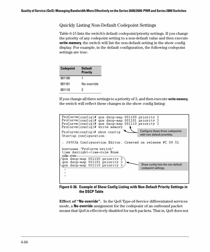
Quality of Service (QoS): Managing Bandwidth More Effectively on the Series 2600/2600-PWR and Series 2800 Switches
Quickly Listing Non-Default Codepoint Settings
Table 6-15 lists the switch’s default codepoint/priority settings. If you change the priority of any codepoint setting to a non-default value and then execute write memory, the switch will list the non-default setting in the show config display. For example, in the default configuration, the following codepoint settings are true:
If you change all three settings to a priority of 3, and then execute write memory, the switch will reflect these changes in the show config listing:
Figure 6-36. Example of Show Config Listing with Non-Default Priority Settings inthe DSCP Table
Effect of “No-override”. In the QoS Type-of-Service differentiated services mode, a No-override assignment for the codepoint of an outbound packet means that QoS is effectively disabled for such packets. That is, QoS does not
Codepoint Default Priority
001100 1
001101 No-override
001110 2
Configure these three codepoints with non-default priorities.
Show config lists the non default codepoint settings.
6-66

Quality of Service (QoS): Managing Bandwidth More Effectively on the Series 2600/2600-PWR and Series 2800 SwitchesUsing QoS Classifiers To Configure QoS for Outbound Traffic
affect the packet queuing priority or VLAN tagging. In this case, the packets are handled as follows (as long as no other QoS feature creates priority assignments for them):
Note On Changing a Priority Setting
If a QoS classifier is using a policy (codepoint and associated priority) in the DSCP Policy table, you must delete or change this usage before you can change the priority setting on the codepoint. Otherwise the switch blocks the change and displays this message:
Cannot modify DSCP Policy < codepoint > - in use by other qos rules.
In this case, use show qos < classifier > to identify the specific classifiers using the policy you want to change; that is:
show qos device-priorityshow qos port-priorityshow qos tcp-udp-port-priorityshow qos vlan-priorityshow qos type-of-service
For example, suppose that the 000001 codepoint has a priority of 6, and several classifiers use the 000001 codepoint to assign a priority to their respective types of traffic. If you wanted to change the priority of codepoint 000001 you would do the following:
1. Identify which QoS classifiers use the codepoint.
2. Change the classifier configurations by assigning them to a different DSCP policy, or to an 802.1p priority, or to No-override.
3. Reconfigure the desired priority for the 000001 codepoint.
4. Either reassign the classifiers to the 00001 codepoint policy or leave them as they were after step 2, above.
802.1Q Status Outbound 802.1p Priority
Received and Forwarded on a tagged port member of a VLAN. Unchanged
Received on an Untagged port member of a VLAN; Forwarded on a tagged port member of a VLAN.
0 (zero)—”normal”
Forwarded on an Untagged port member of a VLAN. None
6-67

Quality of Service (QoS): Managing Bandwidth More Effectively on the Series 2600/2600-PWR and Series 2800 Switches
Example of Changing the Priority Setting on a Policy When One or More Classifiers Are Currently Using the Policy
Suppose that codepoint 000001 is in use by one or more classifiers. If you try to change its priority, you see a result similar to the following:
Figure 6-37. Example of Trying To Change the Priority on a Policy In Use by a Classifier
In this case, you would use steps similar to the following to change the priority.
1. Identify which classifiers use the codepoint you want to change.
6-68

Quality of Service (QoS): Managing Bandwidth More Effectively on the Series 2600/2600-PWR and Series 2800 SwitchesUsing QoS Classifiers To Configure QoS for Outbound Traffic
Figure 6-38. Example of a Search to Identify Classifiers Using a Codepoint You Want To Change
Three classifiers use the codepoint that is to be changed.
Two classifiers do not use the codepoint that is to be changed.
6-69

Quality of Service (QoS): Managing Bandwidth More Effectively on the Series 2600/2600-PWR and Series 2800 Switches
2. Change the classifier configurations by assigning them to a different DSCP policy, or to an 802.1p priority, or to No-override. For example:
a. Delete the policy assignment for the device-priority classifier. (That is, assign it to No-override.)
b. Create a new DSCP policy to use for re-assigning the remaining classifiers.
c. Assign the port-priority classifier to the new DSCP policy.
d. Assign the udp-port 1260 classifier to an 802.1p priority.
3. Reconfigure the desired priority for the 000001 codepoint.
ProCurve(config)# qos dscp-map 000001 priority 4
4. You could now re-assign the classifiers to the original policy codepoint or leave them as currently configured.
6-70

Quality of Service (QoS): Managing Bandwidth More Effectively on the Series 2600/2600-PWR and Series 2800 SwitchesIP Multicast (IGMP) Interaction with QoS
IP Multicast (IGMP) Interaction with QoSIGMP high-priority-forward causes the switch to service the subscribed IP multicast group traffic at high priority, even if QoS on the switch has relegated the traffic to a lower priority. This does not affect any QoS priority settings, so the QoS priority is honored by downstream devices. However, QoS does take precedence over IGMP normal-priority traffic.
The switch’s ability to prioritize IGMP traffic for either a normal or high priority outbound queue overrides any QoS criteria, and does not affect any 802.1p priority settings the switch may assign. For a given packet, if both IGMP high priority and QoS are configured, the QoS classification occurs and the switch marks the packet for downstream devices, but the packet is serviced by the high-priority queue when leaving the switch.
QoS Messages in the CLI
IGMP High Priority
QoS Configuration Affects Packet
Switch Port Output Queue
Outbound 802.1p Setting (Requires Tagged VLAN)
Not Enabled Yes Determined by QoS Determined by QoS
Enabled See above para-graph.
High As determined by QoS if QoS is active.
Message Meaning
DSCP Policy < decimal-codepoint > not configured
You have attempted to map a QoS classifier to a codepoint for which there is no configured priority (No-override). Use the qos dscp-map command to configure a priority for the codepoint, then map the classifier to the codepoint.
Cannot modify DSCP Policy < codepoint > - in use by other qos rules.
You have attempted to map a QoS classifier to a codepoint that is already in use by other QoS classifiers. Before remapping the codepoint to a new priority, you must reconfigure the other QoS classifiers so that they do not use this codepoint. You can have multiple QoS classifiers use this same codepoint as long as it is acceptable for all such classifiers to use the same priority.
6-71

Quality of Service (QoS): Managing Bandwidth More Effectively on the Series 2600/2600-PWR and Series 2800 Switches
QoS Operating Notes and RestrictionsTable 6-16. Details of Packet Criteria and Restrictions for QoS Support
■ All Switches: For explicit QoS support of IP subnets, ProCurve recom-mends forcing IP subnets onto separate VLANs and then configuring VLAN-based classifiers for those VLANs.
■ For Devices that Do Not Support 802.1Q VLAN-Tagged Ports: For communication between these devices and the switch, connect the device to a switch port configured as Untagged for the VLAN in which you want the device’s traffic to move.
■ Port Tagging Rules: For a port on the switch to be a member of a VLAN, the port must be configured as either Tagged or Untagged for that VLAN. For more on VLANs, refer to chapter 2, “Static Virtual LANs (VLANs)”.
■ SAP-Encapsulated Packet Restriction: Except for source-port QoS and VLAN QoS, the Series 2600/2600-PWR and 2800 switches do not support QoS operation for SAP-Encapsulated packets. Thus, the switch can use only VLAN QoS and source-port QoS to prioritize SAP-encapsulated packets.
■ Packets with IP Option Fields in the Header: UDP/TCP QoS is not supported for IP packets carrying optional fields in their headers.
Packet Criteria or Restriction
QoS Classifiers DSCP Overwrite (Re-Marking)
UDP/TCP Device Priority (IP Address)
IP Type-of-Service
VLAN SourcePort
Incoming 802.1p
Restricted to IPv4 Packets Only Yes Yes Yes No No No Yes
Allow Packets with IP Options1 No Yes Yes Yes Yes Yes Yes
Support IPv6 Packets2 No No No Yes Yes Yes No
Support Layer-2 SAP Encapsulation
No No No Yes Yes Yes No
1An “IP Option” is an optional, extra field in the header of an IP packet. If the switch is configured with a UDP/TCP classifier and a packet with an IP option is received, the switch uses the next-highest classifier, if configured. 2All Switches: For explicit QoS support of IPv6 packets, force IPv6 traffic into its own set of VLANs and then configure VLAN-based classifiers for those VLANs.
6-72

Quality of Service (QoS): Managing Bandwidth More Effectively on the Series 2600/2600-PWR and Series 2800 SwitchesQoS Operating Notes and Restrictions
■ RADIUS Authentication: RADIUS authentication allowing traffic through a given port may override the port’s QoS configuration, which generates an Event Log message. When the authenticated host discon-nects, the port returns to the static QoS configuration.
■ Maximum QoS Configuration Entries: The Series 2600/2600-PWR and 2800 switches accept the maximum outbound priority and/or DSCP policy configuration entries shown in table 6-17.
Table 6-17. Maximum QoS Entries.
Attempting to exceed the above limits generates the following message in the CLI:
Unable to add this QoS rule. Maximum number (entry-#) already reached.
■ All Switches—Not Supported: Use of an inbound 802.1p packet priority as a classifier for remapping a packet’s outbound priority to different 802.1p priority. For example, where inbound packets carry an 802.1p priority of 1, QoS cannot be configured use this priority as a classifier for changing the outbound priority to 0.
Switch Software Version
Maximum QoS Entries (Rules)
Notes for All Switch Models
Series 2800 E.08.01 and greater
1201 • Each device (IP address) QoS configuration uses two port rules.2
• Each TCP/UDP port QoS configuration uses two port rules.2
• ToS IP precedence uses eight port rules.2
• All other classifier configurations use one port rule each.2
Series 2600/2600-PWR
H.08.xx Gig Ports: 1201
10/100 Ports: 2481
1Configuring one or more QoS entries reduces this maximum. 2For more information, refer to tables 6-9 and 6-10 on page 6-17.
6-73

Quality of Service (QoS): Managing Bandwidth More Effectively on the Series 2600/2600-PWR and Series 2800 Switches
— This page is intentionally unused. —
6-74