quality people, quality products turbo-max 6100 …
TRANSCRIPT

QUALITY PEOPLE, QUALITY PRODUCTS
Sioux Automation Center, Inc.• 877 1st Ave NW • Sioux Center, IA 51250PH: (712-722-1488) • Toll Free: 1-866-722-1488
www.siouxautomation.com
ASSEMBLYCALIBRATIONOPERATIONREPLACEMENT PARTS
READ COMPLETE MANUAL CAREFULLYBEFORE ATTEMPTING OPERATION
4/12210
MON600191
REV B
OPERATORS/PARTS MANUAL
TURBO-MAX
6100 SERIES TRAILER
Page 2
Never overload wagon. Follow rating of gear or rating of tires, whichever is less.
Ensure that anybody present is clear before applying power to any machinery used in conjunc-
tion with wagon box or when moving box.
Never allow anyone in, near, or on mixing chamber during mixing, transporting, or unloading
of feed.
Do not exceed 20 miles per hour when towing wagon.
GENERAL INFORMATION
1. Unless otherwise specifi ed, high-strength (grade5) (3
radial-line head markings) hex head bolts are used
throughout assembly of this piece of equipment.
2. Whenever terms “LEFT” and “RIGHT” are used in this
manual it means from a position behind the wagon box
and facing forward.
3. When placing a parts order, refer to this manual for
proper part numbers and place order by PART NO. and
DESCRIPTION.
4. Read assembly instructions carefully. Study
assembly procedures and all illustrations before you begin
assembly. Note which parts are used in each step. This
unit must be assembled in proper sequence or complica-
tions will result.
WARNING: TO AVOID PERSONAL INJURY OR DEATH, OBSERVE FOLLOWING
INSTRUCTIONS:
Thank you for purchasing a Sioux Automation Turbo-Max 6100 ser ies reel mixer. We feel you have
made a wise choice and hope you are completely satisfied with your new piece of equipment. Your new 6100
series Turbo-Max is a durable, effi cient, and easy to use unit. Proper care and use will result in many years of service.
INTRODUCTION
Table of Contents
General Information ................................................................................................................................................ 2
Model and Serial Number Identifi cation...................................................................................................................3
Safety, Signal Words ............................................................................................................................................... 4
Equipment Safety Guidelines .................................................................................................................................. 5
Lighting and Marking ............................................................................................................................................... 5
Safety Sign Care ..................................................................................................................................................... 5
Tire Safety ............................................................................................................................................................... 6
Before Operation ..................................................................................................................................................... 6
During Operation ....................................................................................................................................................7-8
Following Operation ................................................................................................................................................ 8
Highway and Transport Operations .......................................................................................................................8-9
Performing Maintenance ........................................................................................................................................ 10
Bolt Torque ............................................................................................................................................................. 11
PTO Horsepower Requirements ............................................................................................................................ 12
Drawbar Attaching System ..................................................................................................................................... 12
Hydraulic System ................................................................................................................................................... 12
Mixer Setup ............................................................................................................................................................ 12
Mixer Operation ...................................................................................................................................................13-15
Inspection and Adjustment ...................................................................................................................................15-16
Electronic Scales ................................................................................................................................................... 16
Lubrication ............................................................................................................................................................. 17
Decal Location ....................................................................................................................................................... 18
Model Specifi cations .............................................................................................................................................. 19
Box Base Assembly .............................................................................................................................................20-23
Reel Assembly .......................................................................................................................................................24
Wiper Tube Assembly ........................................................................................................................................... 25
Poly Bearing Assembly ......................................................................................................................................... 26
6141 Auger Assemblies ....................................................................................................................................... 27
Trailer Base Assembly .........................................................................................................................................28-29
Subframe Assembly ............................................................................................................................................. 30
Hub & Spindle Assemblies ................................................................................................................................... 31
Final Assembly .................................................................................................................................................... 32
Slide Tray Breakdown ......................................................................................................................................... 33
Power Discharge Breakdown ...............................................................................................................................34-35
Hydraulics Breakdown .........................................................................................................................................36-40
Control Box Breakdown ........................................................................................................................................ 41
1000 RPM PTO Conversion ................................................................................................................................. 42
Driveline Assembly ..............................................................................................................................................43-44
Lighting Breakdown ............................................................................................................................................... 45
Warranty ...............................................................................................................................................................46-47
Page 3
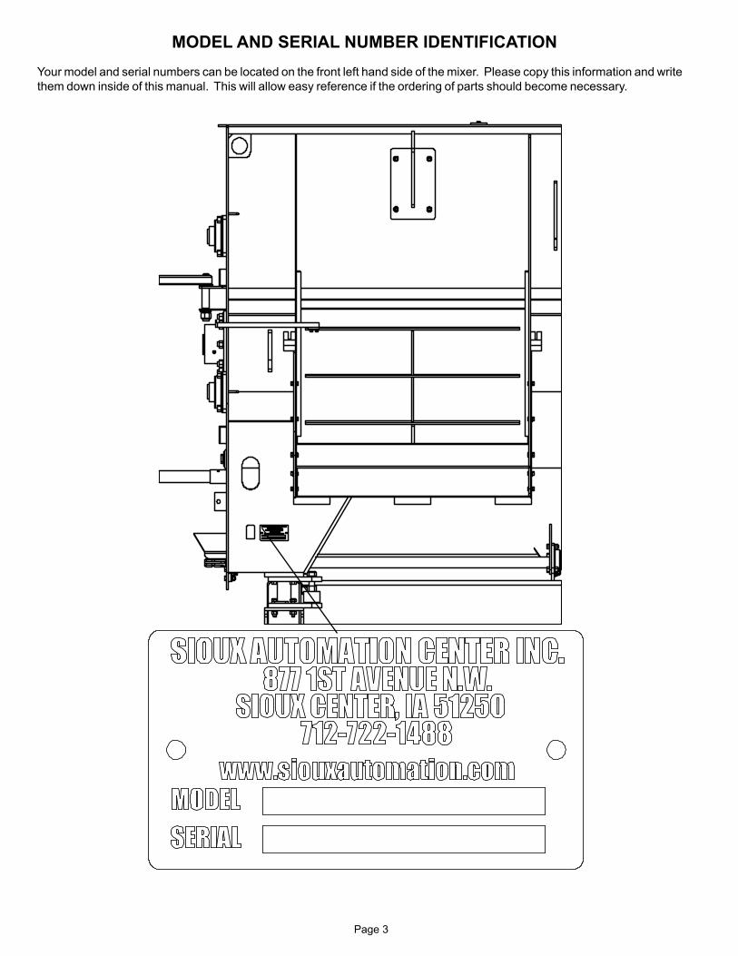
MODEL AND SERIAL NUMBER IDENTIFICATION
Your model and serial numbers can be located on the front left hand side of the mixer. Please copy this information and write
them down inside of this manual. This will allow easy reference if the ordering of parts should become necessary.

Page 4
SAFETY, SIGNAL WORDS
SAFETY
TAKE NOTE! THIS SAFETY ALERT SYMBOL FOUND THROUGHOUT THIS
MANUAL IS USED TO CALL YOUR ATTENTION TO INSTRUCTIONS INVOLVING YOUR
PERSONAL SAFETY AND THE SAFETY OF OTHERS. FAILURE TO FOLLOW THESE
INSTRUCTIONS CAN RESULT IN INJURY OR DEATH!
THIS SYMBOL MEANS
ATTENTION!
BECOME ALERT!
YOUR SAFETY IS INVOLVED!
SIGNAL WORDS
Note the use of the signal words DANGER, WARNING
and CAUTION with the safety messages. The appropriate
signal word for each has been selected using the following
guidelines:
DANGER:
Indicates an imminently hazardous situation that, if not
avoided, will result in serious injury or death. This signal
word is to be limited to most extreme situations typically for
machine components which, for functional purposes, cannot
be guarded.
WARNING:
Indicates a potentially hazardous situation that, if not avoided,
could result in serious injury or death, and includes hazards
that are exposed when guards are removed. It may also be
used to alert against unsafe practices.
CAUTION:
Indicates a potentially hazardous situation that, if not avoided,
may result in minor or moderate injury. It may also be used
to alert against unsafe practices.
If you have questions not answered in this manual, require additional copies, or if your manual is damaged, please contact
your dealer or Sioux Automation Center Inc., 877 1st Ave NW, Sioux Center, IA 51250, ph: (712) 722-1488 or
Toll Free: 1-866-722-1488, Fax: (712) 722-1487 http://www.siouxautomation.com

Page 5
SAFETY...YOU CAN LIVE WITH IT
EQUIPMENT SAFETY GUIDELINESEvery year many accidents occur which could have been avoided by a few seconds of thought and a more
careful approach to handling equipment. You, the operator, can avoid many accidents by observing the following
precautions in this section. To avoid personal injury, study the following precautions and insist those working
with you, and you yourself, follow them.
In order to provide a better view, certain illustrations in this manual may show an assembly with a safety shield
removed. However, equipment should never be operated in this condition. Keep all shields in place. If shield
removal becomes necessary for repairs, replace shield prior to use.
Replace any CAUTION, WARNING, DANGER or instruction safety decal that is not readable or is missing.
Location of such decals is indicated in this manual. The part numbers for the decals are located in the lower
right hand corner of the decal, and listed in this manual on the following pages.
Do not attempt to operate this equipment under the infl uence of alcohol or drugs.
Review safety instructions with all users annually.
Operator should be a responsible adult. DO NOT ALLOW PERSONS TO OPERATE OR ASSEMBLE
THIS UNIT UNTIL THEY HAVE READ THIS MANUAL AND HAVE DEVELOPED A THOROUGH
UNDERSTANDING OF THE SAFETY PRECAUTIONS AND PROPER OPERATIONAL
PROCEDURES.
Do not paint over, remove, or deface any safety signs or warning decals on your equipment. Observe all safety
signs and practice the instructions on them.
Never exceed limits of a piece of machinery. If its ability to do a job, or to do so safely is in question DON’T
TRY IT.
LIGHTING AND MARKINGIt is the responsibility of customer to know lighting and marking requirements of the local highway authorities
and to install and maintain the equipment to provide compliance with the regulations. Add extra lights when
transporting at night or during periods of limited visibility. Lighting kits are available from your dealer or from
manufacturer.
SAFETY SIGN CARE• Keep safety signs clean and legible at all times.
• Replace safety signs that are missing or have become illegible.
• Replaced parts that displayed safety signs should also display current safety sign.
• Safety signs are available from your distributor, dealer parts department, or the factory.
How to install safety signs:
• Be sure that installation area is clean and dry.
• Decide on exact position before you remove backing paper.
• Remove smallest portion of split backing paper.
• Align decal over specifi ed area and carefully press small portion with exposed sticky backing in place.
• Slowly peel back remaining paper and carefully smooth remaining portion of decal into place.
• Small air pockets can be pierced with a pin and smoothed out using piece of decal backing paper.
Page 6
TIRE SAFETY
• Failure to follow proper procedures when mounting a tire on a rim can produce an explosion which may
result in a serious injury or death.
• Do not attempt to mount a tire unless you have proper equipment and experience to do the job.
• Infl ating or servicing tires can be dangerous. Whenever possible, trained personnel should be called to
service and/or mount tires.
• Always order and install tires and wheels with appropriate type and load capacity to meet or exceed
anticipated weight to be placed on the equipment.
REMEMBER
Your best assurance against accidents is a careful and responsible operator. If there is any
portion of this manual or function you do not understand, contact your local authorized dealer
or manufacturer.
BEFORE OPERATION:
• Carefully study and understand this manual.
• Do not wear loose-fi tting clothing which may catch in moving parts.
• Always wear protective clothing and substantial shoes.
• It is recommended that suitable hearing and eye protection be worn.
• Operator may come in contact with certain materials which may require specifi c safety equipment
relative to handling of such materials.
• Keep wheel and lug nuts tightened to specifi ed torque.
• Assure that agricultural implment tires are infl ated evenly.
• Give unit a visual inspection for any loose bolts, worn parts or cracked welds, and make necessary
repairs. Follow the maintenance safety instructions included in this manual.
• Be sure there are no tools lying on or in equipment.
• Do not use unit until you are sure that area is clear, especially around children and animals.
• Don’t hurry the learning process or take the unit for granted. Ease into it and become familiar
with your new equipment.
• Practice operation of your equipment and its attachments. Completely familiarize yourself and other
operators with its operation before using.
• Use a tractor equipped with Roll Over Protection System (ROPS) and fasten your seat belt prior to
starting the engine.
• Manufacturer does not recommend usage of a tractor with the ROPS removed.
• Make sure that brakes are evenly adjusted.
• Move tractor wheels to widest recommended settings to increase stability.
• Do not allow anyone to stand between tongue or hitch and towing vehicle when backing up to equipment.
• NEVER load mixer without fi rst attaching a tractor of at least 2/3 the gross trailer weight.

Page 7
DURING OPERATION
• Be aware of bystanders, PARTICULARLY CHILDREN! Always look around to make sure that it is safe to
start the engine or to move the unit. This is particularly important with higher noise levels and quiet cabs, as you
may not hear people shouting.
• NO PASSENGERS ALLOWED- Do not allow anyone to ride on or inside the mixer at any time!
• Keep hands and clothing clear of moving parts.
• Do not clean, lubricate, or adjust your equipment while it is moving.
• When halting operation, even periodically, set parking brakes, disengage PTO, shut off
engine, and remove ignition key.
• Be especially observant of the operating area and terrain. Watch for holes, rocks, or other hidden hazards.
Always inspect area prior to operation.
- DO NOT operate near edge of drop-offs or banks.
- DO NOT operate on steep slopes as overturn may result.
- Operate up and down (not across) intermediate slopes. Avoid sudden starts and stops.
• Pick the most level possible route when transporting across fi elds. Avoid edges of ditches, gullies, and steep
hillsides.
• Be extra careful when working on inclines.
• Maneuver tractor or towing vehicle at safe speeds.
• Avoid overhead wires or other obstacles. Contact with overhead lines could cause serious injury or death.
• Avoid loose gravel, rocks, and holes; they can be dangerous for equipment operation or movement.
• Allow for unit length when making turns.
• Do not walk or work under raised components or attachments unless securely positioned and blocked.
• Keep all bystanders, pets, and livestock clear of work area.
• Operate towing vehicle from operators seat only.
• Never stand alongside of unit with engine running or attempt to start engine and/or operate machine while
standing alongside of unit.
• Never leave running equipment unattended.
• As a precaution, always recheck hardware on equipment following every 100 hours of operation. Correct all
problems. Follow maintenance safety procedures.
• Never hand feed materials into mixer while it is running. Rotating augers inside mixer may not be visible from
the loading point, and may cut or grab hands, clothing, or material being loaded, causing severe injury.
Always stop tractor engine before hand loading materials.
• Do not allow operation of this unit by inexperienced or unqualifi ed people. Keep all unqualifed people away
from the mixer during operation. Operators of this unit must be alert and use good judgement at all
times. Operator should not climb on ladder or any part of the mixer when loading, mixing, or unloading material.
• Be sure the inside of the mixer is clear of any obstruction before operating.
Page 8
• Use caution when working around the discharge area. Stay clear of power chute & slide tray. These are
controlled from the cab and could operate without warning, creating pinch points which could cause severe
injury or death. Always stop tractor engine and remove PTO driveline & hydraulic hoses before working
near the discharge area.
• Never attempt to release jammed materials or clean materials from any area of the mixer or discharge
chute without stopping engine and removing driveline fi rst. Moving parts can be hidden by materials, and
stopped parts can start unexpectedly, causing severe injury. Always stop tractor engine and remove the PTO
driveline so that the mixer before attempting to remove jammed material or to clean.
• Never put arms or feet inside unit, power chute, or near discharge door opening, nor climb on or in the mixer
while it is running. NEVER allow anyone to position themselves over or near the top of the mixer while it is
running. Rotating augers and sprockets can grab clothing or create pinch points which can cause severe
injury or death to the operator or bystanders. Always stop tractor engine and remove the PTO driveline so
that the mixer cannot be accidentally turned on while inspecting, servicing, repairing, or cleaning.
• Following operation, or when unhitching, stop tractor or towing vehicle, set brakes, shut off engine and
remove the ignition key.
• Store unit in an area away from human activity.
• Do not park equipment where it will be exposed to livestock for long periods of time. Damage and
livestock injury could result.
• Do not permit children to play on or around stored unit.
• Make sure all parked machines are on a hard, level surface and engage all safety devices.
• Wheel chocks may be needed to prevent unit from rolling.
FOLLOWING OPERATION
HIGHWAY AND TRANSPORT OPERATIONS
• SAFETY CHAINS: If equipment is going to be transported on a public highway, always follow state and
local regulations regarding safety chains and auxiliary lighting. Be sure to check with local law enforcement
agencies for your own particular regulations. If required, safety chains should be obtaines and installed
Only safety chains (not elastic or nylon/plastic tow straps) should be used to retain connection between
towing and towed machines in the event of separation of primary attaching system. Use a high strength,
appropriately sized hitch pin with a mechanical retainer and attach safety chains. Criss cross chains under
tongue and secure to draw bar cage, mounting loops, or bumper frame.
• Adopt safe driving practices:
- Keep brake pedals latched together at all times. NEVER USE INDEPENDENT BRAKING WITH
MACHINE IN TOW, LOSS OF CONTROL AND/OR UPSET OF UNIT CAN RESULT.
- Always drive at a safe speed relative to local conditions, ensure that your speed is low enough for an
emergency stop. Keep speed to a minimum.
- Reduce speed prior to turns to avoid risk of overturning.
- Always keep tractor or towing vehicle in gear to provide engine braking when going downhill.
Do not coast.
- Do not drink and drive!

Page 9
Comply with state and local laws governing highway safety and movement of farm machinery on public
roads.
Use approved accessory lighting, fl ags and necessary warning devices to protect operators of other vehicles
on highway during transport. Various safety lights and devices are available from your dealer.
Use of fl ashing amber lights is acceptable in most localities. However, some localities prohibit their use.
Local laws should be checked for all highway lighting and marking requirements.
When driving tractor and equipment on road under 20 m.p.h. (40 kph) at night or during day, use fl ashing
amber warning lights and a slow moving vehicle (SMV) identifi cation emblem.
Plan your route to avoid heavy traffi c.
Be a safe and courteous driver. Always yield to oncoming traffi c in all situations, including narrow bridges,
intersections, etc.
Be observant of bridge load ratings. Do not cross bridges rated lower than gross weight at which you are
operating.
Watch for obstructions overhead and side to side while transporting.
Always operate equipment in a position to provide maximum visibility. Make allowances for increased length
and weight of equipment when making turns, stopping unit, etc.
•
•
•
•
•
•
•
•
•
Page 10
Good maintenance is your responsibility. Poor maintenance is an invitation for trouble.
Make sure there is plenty of ventilation. Never operate engine in a closed building. Exhaust fumes may
cause asphyxiation.
Before working on this machine, stop towing vehicle, set brakes, shut off engine and remove ignition
key.
Always use safety support and block wheels. Never use a jack to support machine.
Always use proper tools or equipment for job at hand.
Use extreme caution when making adjustments.
Follow torque chart in this manual when tightening bolts and nuts.
Never use your hands to locate a hydraulic leak on attachments. Use a small piece of cardboard or wood.
Hydraulic fl uid escaping under pressure can penetrate skin.
Openings in skin and minor cuts are susceptible to infection from hydraulic fl uid. Without immediate
medical treatment, serious infection and reactions can occur.
When disconnecting hydraulic lines, shut off hydraulic supply and relieve all hydraulic pressure.
Replace all shields and guards after servicing and before moving equipment.
After servicing, be sure all tools, parts, and service equipment are removed.
Do not allow grease or oil to build up on any step or platform.
When replacing bolts, refer to owner’s manual.
Refer to bolt torque chart for head identifi cation marking.
Where replacement parts are necessary for periodic maintenance and servicing, genuine factory
replacement parts must be used to restore your equipment to original specifi cations. Manufacturer will
not claim responsibility for use of unapproved parts or accessories and other damages as a result of their
use.
If equipment has been altered in any way from original design, manufacturer does not accept any liability
for injury or warranty.
A fi re extinguisher and fi rst aid kit should be kept readily accessible while performing maintenance on this
equipment.
•
•
•
•
•
•
•
•
•
•
•
•
•
•
•
•
•
•
PERFORMING MAINTENANCE
Page 11
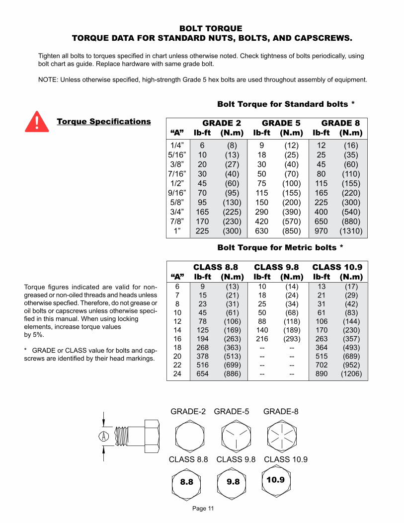
BOLT TORQUE
TORQUE DATA FOR STANDARD NUTS, BOLTS, AND CAPSCREWS.
Tighten all bolts to torques specifi ed in chart unless otherwise noted. Check tightness of bolts periodically, using
bolt chart as guide. Replace hardware with same grade bolt.
NOTE: Unless otherwise specifi ed, high-strength Grade 5 hex bolts are used throughout assembly of equipment.
Bolt Torque for Standard bolts *
GRADE 2 GRADE 5 GRADE 8
“A” lb-ft (N.m) lb-ft (N.m) lb-ft (N.m)
1/4” 6 (8) 9 (12) 12 (16)
5/16” 10 (13) 18 (25) 25 (35)
3/8” 20 (27) 30 (40) 45 (60)
7/16” 30 (40) 50 (70) 80 (110)
1/2” 45 (60) 75 (100) 115 (155)
9/16” 70 (95) 115 (155) 165 (220)
5/8” 95 (130) 150 (200) 225 (300)
3/4” 165 (225) 290 (390) 400 (540)
7/8” 170 (230) 420 (570) 650 (880)
1” 225 (300) 630 (850) 970 (1310)
Torque fi gures indicated are valid for non-
greased or non-oiled threads and heads unless
otherwise specfi ed. Therefore, do not grease or
oil bolts or capscrews unless otherwise speci-
fi ed in this manual. When using locking
elements, increase torque values
by 5%.
* GRADE or CLASS value for bolts and cap-
screws are identifi ed by their head markings.
Torque Specifi cations
CLASS 8.8 CLASS 9.8 CLASS 10.9
“A” lb-ft (N.m) lb-ft (N.m) lb-ft (N.m)
6 9 (13) 10 (14) 13 (17)
7 15 (21) 18 (24) 21 (29)
8 23 (31) 25 (34) 31 (42)
10 45 (61) 50 (68) 61 (83)
12 78 (106) 88 (118) 106 (144)
14 125 (169) 140 (189) 170 (230)
16 194 (263) 216 (293) 263 (357)
18 268 (363) -- -- 364 (493)
20 378 (513) -- -- 515 (689)
22 516 (699) -- -- 702 (952)
24 654 (886) -- -- 890 (1206)
Bolt Torque for Metric bolts *
GRADE-2 GRADE-5 GRADE-8
8.8 10.99.8
CLASS 8.8 CLASS 9.8 CLASS 10.9

Page 12
PTO HORSEPOWER REQUIREMENTS
PTO horsepower requirements are based on most normal dairy or beef rations. Horsepower requirements
may vary depending on the ration or material to be mixed.
Refer to tractor weight requirements for these recommendations and transporting safety precautions for ad-
ditional tractor and towing requirements.
•
•
DRAWBAR ATTACHING SYSTEM
Adjust tractor drawbar and/or the mixer clevis hitch so that the mixer is approximtely level. The top of the
drawbar should be 8”-12” below the tractor PTO shaft. Adjust the drawbar horizontally so that the hitch pin
hole is 14”-16” behind the tractor PTO and the drawbar is centered and locked into place.
A hitch pin with a minumum of 1-1/8” diameter with a retainer pin is recommended for models 6150, 6160,
and 6170.
•
•
HYDRAULIC SYSTEM
Dual hydraulic outlets are required for operating the door and either the slide tray or the powerchute. If your
tractor has only a single set of ports, then the 3 bank valve option should be ordered. On units with the power
chute option, the chute hoses may be diffi cult to connect due to the chute weight on the lift cylinder. Lift weight
off chute cylinder to connect hoses. Tractor hydraulic system requirements are 6 GPM @ 1500 PSI when a
slide tray is used, 15 GPM @2000 PSI when a 3-auger power chute is used.
•
MIXER SETUP
Check for proper assembly, adjustment, and lubrication. Check to see that there is adequate oil in the oil bath. If
power chute is used, oil the roller chains. Check all bolt and set screws are tight.
Be sure all shields are properly in place.
Check for and remove any foreign objects in the mixer hopper and discharge opening.
Check to see that drain plugs are installed and the door is closed.
Be sure no one is inside the mixer.
• Test run the mixer.
• Make sure mixer is empty, then start the mixer.
• Run for at least fi ve minutes at rated PTO RPM.
• Raise and lower the door and operate the chute/slide tray several times.
• Disengage the mixer and turn off the tractor engine and remove driveline.
• Check the mixer drive components to be sure they are not abnormally hot.
If any of these items are not running as indicated, immediately repair or contact your service
representative.
•
•
•
•
•
MIXER RUN-IN
To adjust the height of the power chute, change the length of the link chains on the sides of the chute. For best
performance, the unloading height should be set at the lowest height possible. The discharge tip-off on the power
chute should be adjusted for correct magnet and discharge angle. Remove or loosen the upper bolts, pivot the
tip off to the desired angles and reinstall or retighten all bolts.
•
POWER CHUTE ADJUSTMENT (OPTIONAL)
To avoid personal injury: The hopper fl oor may be slippery and the auger can spin unexpectedly when stepped
on. Use caution when stepping or standing inside the unit, place a protective cover over the auger knives
when work inside the box is required.
Page 13
MIXER OPERATION
Always refer to Equipment Safety Guidelines & Before Operation sections of this manual before operating this mixer.
The Turbo-Max Mixer was designed for blending dairy and beef rations. Most commonly used ingredients, including
limited amounts of dry stem hay, can be mixed quickly and uniformly in this mixer. If you have questions regarding
your feed ration or have other applications, please contact Sioux Automation Center, Inc.
The Turbo-Max Mixer mixing performance can vary greatly according to the differences in materials, loading se-
quence, mixing speed, and unloading methods.
•
•
GENERAL
When the mixer is in operation it has many moving parts which could cause severe injury or death to persons
coming in contact with these parts. To help avoid serious accidents, please read and understand this manual.
•
SAFETY
Do not load hay without other dry commodities in the mixer fi rst to act as a carrier or “lubricant”.
Do not overload hay content, Sioux Automation Center Inc. recommends up to 15%-20% of hay by weight
in the load. Exceeding this percentage can decrease mixing performance or could potentially damage mixer and
cause premature wear on driveline components.
•
•
LIMITATIONS
Do not use tough hay (20%-60% moisture) Always used cured, dry hay. Wet hay, foreign objects or overload-
ing may cause binding and damage to the mixer.
Keep in mind the overall size of the mixer to allow clearance through doorways.
•
•
WARNINGS
The mixer can mix an average load in 3 to 5 minutes. Due to this short mixing time, there is normally no reason
to run the mixer during loading except to level the materials or to breakup hay.
•
MIXING TIME
When deciding when and how fast to operate the mixer, factors such as ingredients being used, the thorough-
ness of the mix, and the time available to mix must be considered. Normal mixing speed is 3/4 to full PTO
speed.
Do not exceed rated PTO speed. When the mixer is operated faster than rated PTO speed the strain on the drive
train and mixer is greatly increased.
•
•
MIXING SPEED
Page 14
• The following feed materials require some preparation or processing to be mixed in the Turbo-Max Mixer:
• ALL LONG AND UNCURED GRASSES
• ROUND BALES, LARGE SQUARE BALES
• SMALL SQUARE BALES
MATERIALS REQUIRING PREPERATION
Always use cured dry hay. Tough hay can cause wrapping, binding and damage to the mixer and can
adversely effect the mixing performance. The following are some examples that contribute to tough hay condi-
tions: high moisture content, high grass content, high density bales,outdoor storage, use of hay preservatives,
and excessive stem length.
•
HAY QUALITY
• Prior to loading, check mixer for foreign objects and be sure door is fully closed.
1. Load Commodities
Adding ingredients like corn, soybean meal, cottonseed, etc. will act as a carrier or “lubricant” if hay is
included in the ration.
If there are few commodities in the ration, substituting corn silage or haylage is preferred.
Fill mixer between 1/3-1/2 full by volume in commodities and forage before adding the hay to the ration.
This will allow enough room for the hay to expand and bring feed level up so the top auger can assist in
processing.
2. Load Hay
Load processed hay. With the mixer running at 3/4 to full PTO speed, proceed loading the small square
bale pieces or tub ground hay into the mixer. Do not exceed 15%-20% of hay by weight.
3. Finish Loading Commodities
Finish loading any other ingredients to complete the ration in order of least binding ingredient to most
binding. Example: dry commodities fi rst, corn silage second, haylage last.
4. Finish Loading Wet Commodities
Any other wet feeds may be added at this time.
5. Add Liquid Ingredients
• If ration includes water, add it last. Adding water at the beginning will cause the hay to bind.
NOTE: DO NOT OVERLOAD MIXER! Overloading causes excessive horsepower requirements, increased strain
on driveline and poor mixer performance.
•
•
•
•
•
•
LOADING AND MIXING
Many different kinds of materials can be mixed with the Turbo-Max Mixer, but each kind of material has its own
unique characteristics.
FORAGES- Chopped hay, corn silage, and fi nely chopped crop residue can be mixed in the mixer. Wet and
heavy forages added in large volumes may require more power to mix.
GRAINS- Ground, rolled, fl aked, and whole cereal grains, minerals, and concentrates, are all very easily mixed,
and can improve the mixing performance of the other materials.
LIQUIDS- Supplements and liquid fat can be blended in the mixer. Some operators prefer adding liquids into
the empty mixer, and others add liquids on top of grains or roughage. Sticky liquids such as molasses tend to
increase the power requirements.
•
•
•
•
MATERIAL THAT CAN BE LOADED DIRECTLY INTO THE MIXER
MIXER OPERATION
Page 15
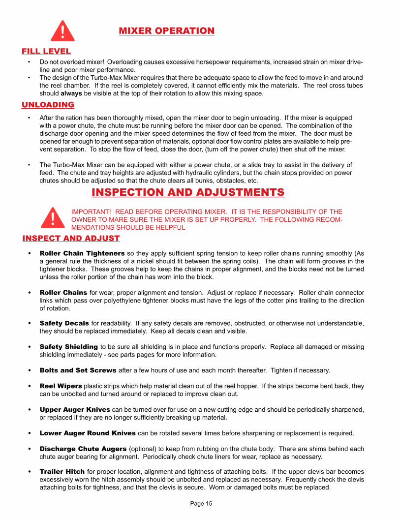
Do not overload mixer! Overloading causes excessive horsepower requirements, increased strain on mixer drive-
line and poor mixer performance.
The design of the Turbo-Max Mixer requires that there be adequate space to allow the feed to move in and around
the reel chamber. If the reel is completely covered, it cannot effi ciently mix the materials. The reel cross tubes
should always be visible at the top of their rotation to allow this mixing space.
•
•
FILL LEVEL
After the ration has been thoroughly mixed, open the mixer door to begin unloading. If the mixer is equipped
with a power chute, the chute must be running before the mixer door can be opened. The combination of the
discharge door opening and the mixer speed determines the fl ow of feed from the mixer. The door must be
opened far enough to prevent separation of materials, optional door fl ow control plates are available to help pre-
vent separation. To stop the fl ow of feed, close the door, (turn off the power chute) then shut off the mixer.
The Turbo-Max Mixer can be equipped with either a power chute, or a slide tray to assist in the delivery of
feed. The chute and tray heights are adjusted with hydraulic cylinders, but the chain stops provided on power
chutes should be adjusted so that the chute clears all bunks, obstacles, etc.
•
•
UNLOADING
MIXER OPERATION
INSPECTION AND ADJUSTMENTS
IMPORTANT! READ BEFORE OPERATING MIXER. IT IS THE RESPONSIBILITY OF THE
OWNER TO MARE SURE THE MIXER IS SET UP PROPERLY. THE FOLLOWING RECOM-
MENDATIONS SHOULD BE HELPFUL
Roller Chain Tighteners so they apply suffi cient spring tension to keep roller chains running smoothly (As
a general rule the thickness of a nickel should fi t between the spring coils). The chain will form grooves in the
tightener blocks. These grooves help to keep the chains in proper alignment, and the blocks need not be turned
unless the roller portion of the chain has worn into the block.
Roller Chains for wear, proper alignment and tension. Adjust or replace if necessary. Roller chain connector
links which pass over polyethylene tightener blocks must have the legs of the cotter pins trailing to the direction
of rotation.
Safety Decals for readability. If any safety decals are removed, obstructed, or otherwise not understandable,
they should be replaced immediately. Keep all decals clean and visible.
Safety Shielding to be sure all shielding is in place and functions properly. Replace all damaged or missing
shielding immediately - see parts pages for more information.
Bolts and Set Screws after a few hours of use and each month thereafter. Tighten if necessary.
Reel Wipers plastic strips which help material clean out of the reel hopper. If the strips become bent back, they
can be unbolted and turned around or replaced to improve clean out.
Upper Auger Knives can be turned over for use on a new cutting edge and should be periodically sharpened,
or replaced if they are no longer suffi ciently breaking up material.
Lower Auger Round Knives can be rotated several times before sharpening or replacement is required.
Discharge Chute Augers (optional) to keep from rubbing on the chute body: There are shims behind each
chute auger bearing for alignment. Periodically check chute liners for wear, replace as necessary.
Trailer Hitch for proper location, alignment and tightness of attaching bolts. If the upper clevis bar becomes
excessively worn the hitch assembly should be unbolted and replaced as necessary. Frequently check the clevis
attaching bolts for tightness, and that the clevis is secure. Worn or damaged bolts must be replaced.
•
•
•
•
•
•
•
•
•
•
INSPECT AND ADJUST

Page 16
Wheel Bolts must be kept properly torqued. Damage to the rim may occur if wheel bolts are not checked fre-
quently.
8-bolt rim: 170 ft lbs-Grade 8 Lug
10-bolt rim: 300 ft lbs-Grade 8 Lug
Tire Wear and Pressure must be checked to ensure that there is no excessive wear, and that tires are infl ated
to the recommended operating pressure for each given tire.
Rain can accumulate in mixer if stored outside, always remove drain plugs on hopper ends to allow unit to
drain completely and replace drain plugs before next use.
Freezing Weather the PTO shield requires extra grease to prevent freezing. Snow can accumulate in mixer
if stored outside, always remove drain plugs on hopper ends to allow unit to drain completely and check hopper
for snow or ice buildup before operating unit. Thaw and remove any obstruction and replace drain plugs before
next use.
IMPORTANT: WHEN WELDING ON THIS UNIT: Do NOT allow the current to fl ow through the bearings,
roller chains, or scale weigh bars. Ground directly to the item being welded. ALWAYS disconnect weigh bar cords
from scale indicator before welding.
•
•
•
•
INSPECT AND ADJUST
INSPECTION AND ADJUSTMENTS
Scale Indicator: Refer to the electronic scale operators manual for adjustment information. The operator’s
manual for the Electroic Scales should be kept with this manual. Additional scale manuals may be obtained
through Sioux Automation Center, Inc.
Load Cells: Should be kept clean, dry,and lubricated to insure dependabiltiy.
Normal Scale Activity: Some warm up scale “drift” may occur after the scale is turned on but should zero
balance within 10-15 minutes. Scale may zero shift over night due to temperature changes.
•
•
•
ELECTRONIC SCALES

Page 17
It is extremely important that the following lubrication schedule be followed: Bearings: use a good
quality multipurpose grease. Replace all damaged or missing grease zerks immediately. Always clean
zerks before using grease gun. Pump the grease in slowly until a slight bead forms around the bearing
seals. Once a month check lines and connections on grease banks for leaks.
Oilbath Oil: Use a good high quality universal oil. Use an oil that meets or exceeds hydraulic oil grade.
Fill to the top lower oilbath roller chains. Change yearly or whenever contaminated.
Before operating a new mixer, the roller chains should be liberally lubricated and then the unit operated
under a no-load condition. This break-in period will allow the roller chains to be thoroughly lubricated and
thus minimize heat-up during operation.
•
•
•
LUBRICATION
�
�
�
�
�
�
�
�����������
INTERVAL COMPONENTS
1 8-10 HOURS
REAR AUGER BEARINGS (6 ZERKS, 3LH & 3RH)
INPUT SHAFT HANGER BEARINGS (5 BEARINGS)
PTO JOINTS (2) AND SLIDE
FRONT AUGER BEARINGS (2 BEARINGS)
DISCHARGE BEARINGS (IF APPLICABLE) AND PIVOTS
2 20 HOURS
DOOR GUIDES AND PIVOTS (SPRAY LUBRICANT)
WHEEL BEARINGS (2)
DISCHARGE CHAINS (IF APPLICABLE)
3 50 HOURS OIL BATH (CHECK LEVEL)
4 ANNUALREPACK WHEEL BEARINGS
DRAIN AND REPLACE OIL BATH OIL

Page 18
DECAL LOCATION
�
��
�
�
�
�
�
�
�
�
�� �� �
���
�
�
�
�
��
��
�
�
�� �
��
��
���
�
��
ITEM # 6150
QTY.
6160
QTY.
6170
QTY.
PART # DESCRIPTION
1 9 9 10 DEC102 DECAL,GRS,GUN,PICTURE
2 5 5 5 DEC105 DECAL,DANGER,DRVLN,ROTATE
3 1 1 1 DEC106 DECAL,CAUTION,MAN,OWNER,5,6
4 1 1 1 DEC107 DECAL,WARNING,CHAIN,EXPOSED
5 1 1 1 DEC108 DECAL,WARNING,PART,MOVING,4,4
6 1 1 1 DEC109 DECAL,CAUTION,WLD,3,3
7 4 4 4 DEC111 DECAL,DANGER,AUGER,5,6
8 1 1 1 DEC154 DECAL,SAC,LOGO,NEW,20.5H,24W
9 1 1 1 DEC442 DECAL,TM,9,228,CS
10 1 1 1 DEC444 DECAL,TM,9,173.75,SS
11 1 1 1 DEC375 DECAL,MODEL,SERIAL,SAC,2.75,5
12 1 1 1 DEC393 DECAL,FEMA,1.5,2.5
13 2 2 2 DEC322 DECAL,WARNING,CHUTE,AREA
14
2 0 0 DEC422 DECAL,TURBOMAX,6150,WHITE
0 2 0 DEC423 DECAL,TURBOMAX,6160,WHITE
0 0 2 DEC424 DECAL,TURBOMAX,6170,WHITE
15 80 80 80 DECREFLECTAPE TAPE,RFLCTV,2”,RED,WHT
16 1 1 1 DECSMV DECAL,VEHICLE,SLOW,MOVE,VINYL
17 1 1 1 STI702174 REFLCTR,RECT,AMBER
18 1 1 1 STI702175 REFLCTR,RECT,RED

Page 19
TURBO-MAX TRAILER SPECIFICATIONSTURBO-MAX TRAILER SPECIFICATIONS
MODEL 6129 6135 6141 6150 6160 6170
DIMENSIONS (INCHES) TRAILER TRAILER TRAILER TRAILER TRAILER TRAILERA - Overall Length 197 220 247 248 278 308
B - Mixing Chamber Length 120 144 168 168 198 228
C - Front Discharge to Bumper 119 143 181 183 213 243
D - Overall Height1 92/994 97 104 114 114 114
RH Drop Side Reduction 14 14 14 14 14 14
E - Tread Width 87 99 100 100 100 103
F - Overall Width (mixer only) 92 92 92 102 102 102
G - Slide Tray - max. reach 18 19 18 18 18 18
- Power Discharge - max reach 2�/3�5 37/47 38/48 37/47 37/47 37/47 37/47
H - Slide Tray - max. height1 22/294 28 35 32 32 32
- Power Discharge - max height 2�/3�5 32/39 39/464 38/45 45/52 42/49 42/49 42/49
I - Slide Tray - transport width 104 107 107 114 114 114
- Power Discharge - transport width 2�/3�5 118/118 121/121 121/121 132/132 132/132 132/132
J - Hinge height for discharge1 33/404 39 46 50 50 50
SPECIFICATIONS
Unit Weight - pounds 9500 12000 13000 16000 18500 21000
Maximum Net Load - pounds 8700 10500 12300 15000 18000 21000
Mixing Capacity - cubic feet 290 350 410 500 600 700
Reel Diameter 62� 62� 62� 70� 70� 70�
Reel Tube - Outside Diameter 6-5/8� 6-5/8� 6-5/8� 8-5/8� 8-5/8� 8-5/8�
Reel Arms 3-1/2� 3-1/2� 3-1/2� 4 1/2� 4 1/2� 4 1/2�
Reel Hopper Thickness 5/16� 5/16� 5/16� 3/8� 3/8� 3/8�
Reel Speed RPM 7.1 7.1 7.1 6.5 6.5 6.5
Lower Auger
Flighting Diameter 20� 20� 20� 24� 24� 24�
Flighting Thickness - Sectional2 1/2� 1/2� 1/2� 5/8�2 5/8�2 5/8�2
Tube - Outside Diameter 5-9/16� 5-9/16� 5-9/16� 6-5/8� 6-5/8� 6-5/8�
Drive Shaft Diameter 3� 3� 3� 4� 4� 4�
Upper Auger
Flighting Diameter 20� 20� 20� 22� 22� 22�
Flighting Thickness - Sectional 3/8� 3/8� 3/8� 1/2� 1/2� 1/2�
Tube - Outside Diameter 5-9/16� 5-9/16� 5-9/16� 6-5/8� 6-5/8� 6-5/8�
Drive Shaft Diameter 3� 3� 3� 3.5� 3.5� 3.5�
Auger Hopper Thickness 5/16� 5/16� 5/16� 3/8� 3/8� 3/8�
Side Sheet Thickness 1/8� 1/8� 1/8� 3/16� 3/16� 3/16�
End Sheet Thickness 1/4� 1/4� 1/4� 1/4� 1/4� 1/4�
Door Opening Size 32.63X20.25 32.63X20.25 40.75X20.50 40.75 x 21.50 40.75 x 21.50 40.75 x 21.50
Roller Chain Drive 60-80-100 80-100-120 80-100-120 100-120-140-160 100-120-140-160 100-120-140-160
Spindle Diameter 2-1/2� 3-3/8� 3-3/8� 3-3/8� 3-3/8� 3-3/8�
Hub HD 8 bolt HD 10 bolt HD 10 bolt HD 10-bolt HD 10-bolt HD 10-bolt
Tongue Weight - % of gross weight empty/full 6% / 10% 6% / 10% 6% / 10% 6% / 10% 5% / 8% 5% / 8%
Minimum Horsepower Requirement - PTO3 60 80 90 100 110 120
PTO Speed 540 540 540/1000 1000 1000 1000
1 Heights and widths will vary with tire size.
2 Lower auger ! ighting at convergence is 3/4� standard.
3 Horsepower requirements will vary by ration components and moisture.
4 Shorter heights based on 225/70x225 tire in low axle position,
Taller heights based on 1100x225 tire in high axle position.
5 6126 & 6135 models use 3-auger discharge, all others use 4-auger.
�
�
�
�
�
�
��
�
�
Page 2
0
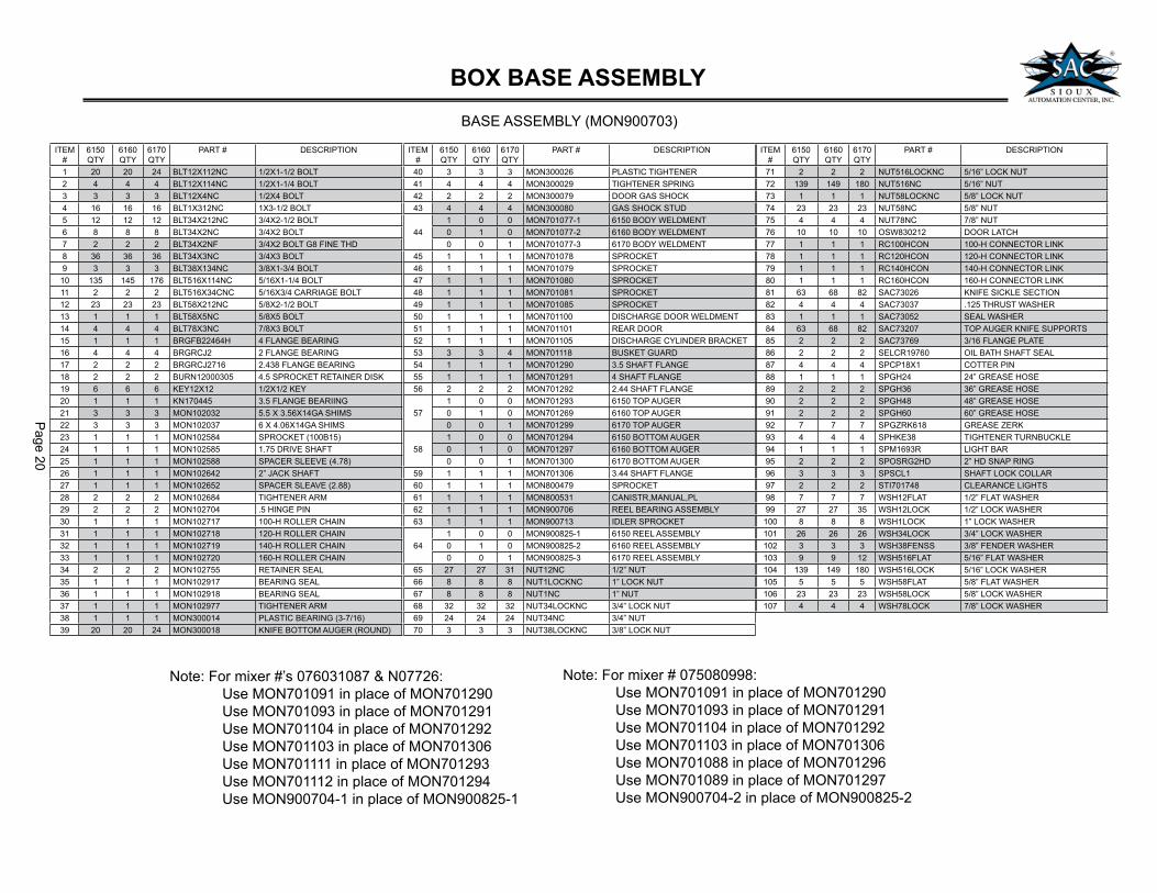
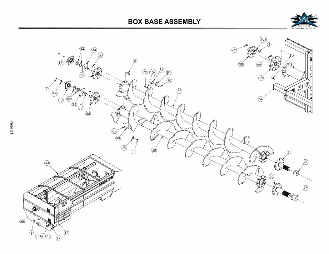
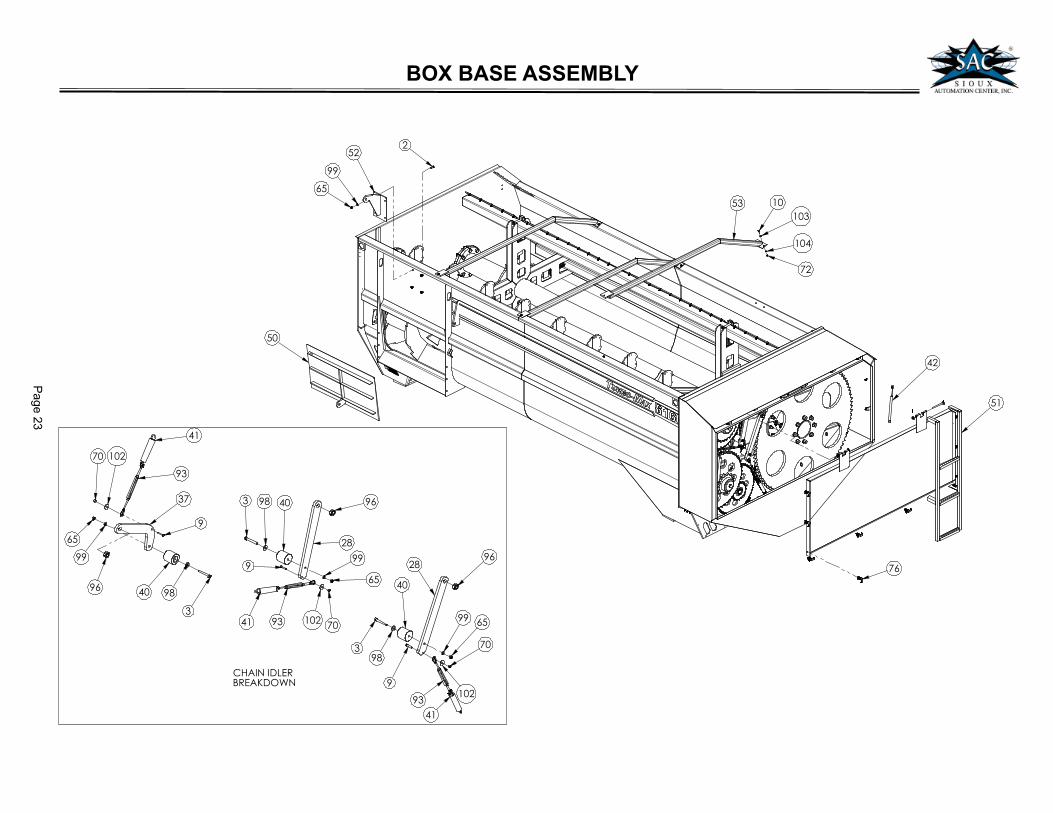
BOX BASE ASSEMBLY
BASE ASSEMBLY (MON900703)
ITEM
#
6150
QTY
6160
QTY
6170
QTY
PART # DESCRIPTION
71 2 2 2 NUT516LOCKNC 5/16” LOCK NUT
72 139 149 180 NUT516NC 5/16” NUT
73 1 1 1 NUT58LOCKNC 5/8” LOCK NUT
74 23 23 23 NUT58NC 5/8” NUT
75 4 4 4 NUT78NC 7/8” NUT
76 10 10 10 OSW830212 DOOR LATCH
77 1 1 1 RC100HCON 100-H CONNECTOR LINK
78 1 1 1 RC120HCON 120-H CONNECTOR LINK
79 1 1 1 RC140HCON 140-H CONNECTOR LINK
80 1 1 1 RC160HCON 160-H CONNECTOR LINK
81 63 68 82 SAC73026 KNIFE SICKLE SECTION
82 4 4 4 SAC73037 .125 THRUST WASHER
83 1 1 1 SAC73052 SEAL WASHER
84 63 68 82 SAC73207 TOP AUGER KNIFE SUPPORTS
85 2 2 2 SAC73769 3/16 FLANGE PLATE
86 2 2 2 SELCR19760 OIL BATH SHAFT SEAL
87 4 4 4 SPCP18X1 COTTER PIN
88 1 1 1 SPGH24 24” GREASE HOSE
89 2 2 2 SPGH36 36” GREASE HOSE
90 2 2 2 SPGH48 48” GREASE HOSE
91 2 2 2 SPGH60 60” GREASE HOSE
92 7 7 7 SPGZRK618 GREASE ZERK
93 4 4 4 SPHKE38 TIGHTENER TURNBUCKLE
94 1 1 1 SPM1693R LIGHT BAR
95 2 2 2 SPOSRG2HD 2” HD SNAP RING
96 3 3 3 SPSCL1 SHAFT LOCK COLLAR
97 2 2 2 STI701748 CLEARANCE LIGHTS
98 7 7 7 WSH12FLAT 1/2” FLAT WASHER
99 27 27 35 WSH12LOCK 1/2” LOCK WASHER
100 8 8 8 WSH1LOCK 1” LOCK WASHER
101 26 26 26 WSH34LOCK 3/4” LOCK WASHER
102 3 3 3 WSH38FENSS 3/8” FENDER WASHER
103 9 9 12 WSH516FLAT 5/16” FLAT WASHER
104 139 149 180 WSH516LOCK 5/16” LOCK WASHER
105 5 5 5 WSH58FLAT 5/8” FLAT WASHER
106 23 23 23 WSH58LOCK 5/8” LOCK WASHER
107 4 4 4 WSH78LOCK 7/8” LOCK WASHER
ITEM
#
6150
QTY
6160
QTY
6170
QTY
PART # DESCRIPTION
1 20 20 24 BLT12X112NC 1/2X1-1/2 BOLT
2 4 4 4 BLT12X114NC 1/2X1-1/4 BOLT
3 3 3 3 BLT12X4NC 1/2X4 BOLT
4 16 16 16 BLT1X312NC 1X3-1/2 BOLT
5 12 12 12 BLT34X212NC 3/4X2-1/2 BOLT
6 8 8 8 BLT34X2NC 3/4X2 BOLT
7 2 2 2 BLT34X2NF 3/4X2 BOLT G8 FINE THD
8 36 36 36 BLT34X3NC 3/4X3 BOLT
9 3 3 3 BLT38X134NC 3/8X1-3/4 BOLT
10 135 145 176 BLT516X114NC 5/16X1-1/4 BOLT
11 2 2 2 BLT516X34CNC 5/16X3/4 CARRIAGE BOLT
12 23 23 23 BLT58X212NC 5/8X2-1/2 BOLT
13 1 1 1 BLT58X5NC 5/8X5 BOLT
14 4 4 4 BLT78X3NC 7/8X3 BOLT
15 1 1 1 BRGFB22464H 4 FLANGE BEARING
16 4 4 4 BRGRCJ2 2 FLANGE BEARING
17 2 2 2 BRGRCJ2716 2.438 FLANGE BEARING
18 2 2 2 BURN12000305 4.5 SPROCKET RETAINER DISK
19 6 6 6 KEY12X12 1/2X1/2 KEY
20 1 1 1 KN170445 3.5 FLANGE BEARIING
21 3 3 3 MON102032 5.5 X 3.56X14GA SHIMS
22 3 3 3 MON102037 6 X 4.06X14GA SHIMS
23 1 1 1 MON102584 SPROCKET (100B15)
24 1 1 1 MON102585 1.75 DRIVE SHAFT
25 1 1 1 MON102588 SPACER SLEEVE (4.78)
26 1 1 1 MON102642 2” JACK SHAFT
27 1 1 1 MON102652 SPACER SLEAVE (2.88)
28 2 2 2 MON102684 TIGHTENER ARM
29 2 2 2 MON102704 .5 HINGE PIN
30 1 1 1 MON102717 100-H ROLLER CHAIN
31 1 1 1 MON102718 120-H ROLLER CHAIN
32 1 1 1 MON102719 140-H ROLLER CHAIN
33 1 1 1 MON102720 160-H ROLLER CHAIN
34 2 2 2 MON102755 RETAINER SEAL
35 1 1 1 MON102917 BEARING SEAL
36 1 1 1 MON102918 BEARING SEAL
37 1 1 1 MON102977 TIGHTENER ARM
38 1 1 1 MON300014 PLASTIC BEARING (3-7/16)
39 20 20 24 MON300018 KNIFE BOTTOM AUGER (ROUND)
ITEM
#
6150
QTY
6160
QTY
6170
QTY
PART # DESCRIPTION
40 3 3 3 MON300026 PLASTIC TIGHTENER
41 4 4 4 MON300029 TIGHTENER SPRING
42 2 2 2 MON300079 DOOR GAS SHOCK
43 4 4 4 MON300080 GAS SHOCK STUD
44
1 0 0 MON701077-1 6150 BODY WELDMENT
0 1 0 MON701077-2 6160 BODY WELDMENT
0 0 1 MON701077-3 6170 BODY WELDMENT
45 1 1 1 MON701078 SPROCKET
46 1 1 1 MON701079 SPROCKET
47 1 1 1 MON701080 SPROCKET
48 1 1 1 MON701081 SPROCKET
49 1 1 1 MON701085 SPROCKET
50 1 1 1 MON701100 DISCHARGE DOOR WELDMENT
51 1 1 1 MON701101 REAR DOOR
52 1 1 1 MON701105 DISCHARGE CYLINDER BRACKET
53 3 3 4 MON701118 BUSKET GUARD
54 1 1 1 MON701290 3.5 SHAFT FLANGE
55 1 1 1 MON701291 4 SHAFT FLANGE
56 2 2 2 MON701292 2.44 SHAFT FLANGE
57
1 0 0 MON701293 6150 TOP AUGER
0 1 0 MON701269 6160 TOP AUGER
0 0 1 MON701299 6170 TOP AUGER
58
1 0 0 MON701294 6150 BOTTOM AUGER
0 1 0 MON701297 6160 BOTTOM AUGER
0 0 1 MON701300 6170 BOTTOM AUGER
59 1 1 1 MON701306 3.44 SHAFT FLANGE
60 1 1 1 MON800479 SPROCKET
61 1 1 1 MON800531 CANISTR,MANUAL,PL
62 1 1 1 MON900706 REEL BEARING ASSEMBLY
63 1 1 1 MON900713 IDLER SPROCKET
64
1 0 0 MON900825-1 6150 REEL ASSEMBLY
0 1 0 MON900825-2 6160 REEL ASSEMBLY
0 0 1 MON900825-3 6170 REEL ASSEMBLY
65 27 27 31 NUT12NC 1/2” NUT
66 8 8 8 NUT1LOCKNC 1” LOCK NUT
67 8 8 8 NUT1NC 1” NUT
68 32 32 32 NUT34LOCKNC 3/4” LOCK NUT
69 24 24 24 NUT34NC 3/4” NUT
70 3 3 3 NUT38LOCKNC 3/8” LOCK NUT
Note: For mixer #’s 076031087 & N07726:
Use MON701091 in place of MON701290
Use MON701093 in place of MON701291
Use MON701104 in place of MON701292
Use MON701103 in place of MON701306
Use MON701111 in place of MON701293
Use MON701112 in place of MON701294
Use MON900704-1 in place of MON900825-1
Note: For mixer # 075080998:
Use MON701091 in place of MON701290
Use MON701093 in place of MON701291
Use MON701104 in place of MON701292
Use MON701103 in place of MON701306
Use MON701088 in place of MON701296
Use MON701089 in place of MON701297
Use MON900704-2 in place of MON900825-2
Page 2
1
BOX BASE ASSEMBLY
��
��
��
��
���
��
��
��
�
��
��
��
��
�
�
���
�
�
��
�
���
����
��
�����
�
��
��
��
��
�
��
��
��
��
���
�
����

Page 2
2
��
��������� ������
����� �������
��
���
����
��
��
��
��
��
��
��
��
��
��
��
��
��
���
��
��
��
����
��
��
��
��
����������������������
����������� �������
��
�
��
��
��
��� ��
��
��
����
��
��
��
��
���
��
�
��
�����
�
��
�� ��
��
���
��
�� �����
���!���
�
���!���
�� �����
��
��
��
����
BOX BASE ASSEMBLY
Page 2
3
��
��
��
���
���
��
��
��
��
��
��
�
��
�� �� �����
���������
��
���
��
�
��
�
��
��
��
� �� �
�
�
�
�
� �� �����
��
��
��
��
�
��
�
����
����
��
�����
�
BOX BASE ASSEMBLY
Page 24
�
�
�
�
�
�
�
�
�
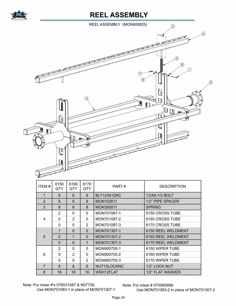
ITEM #6150
QTY
6160
QTY
6170
QTYPART # DESCRIPTION
1 8 8 8 BLT12X612NC 1/2X6-1/2 BOLT
2 8 8 8 MON102611 1/2” PIPE SPACER
3 8 8 8 MON300011 SPRING
4
2 0 0 MON701087-1 6150 CROSS TUBE
0 2 0 MON701087-2 6160 CROSS TUBE
0 0 2 MON701087-3 6170 CROSS TUBE
5
1 0 0 MON701307-1 6150 REEL WELDMENT
0 1 0 MON701307-2 6160 REEL WELDMENT
0 0 1 MON701307-3 6170 REEL WELDMENT
6
2 0 0 MON900705-1 6150 WIPER TUBE
0 2 0 MON900705-2 6160 WIPER TUBE
0 0 2 MON900705-3 6170 WIPER TUBE
7 8 8 8 NUT12LOCKNC 1/2” LOCK NUT
8 16 16 16 WSH12FLAT 1/2” FLAT WASHER
REEL ASSEMBLY
REEL ASSEMBLY (MON900825)
Note: For mixer #’s 076031087 & N07726:
Use MON701083-1 in place of MON701307-1Note: For mixer # 075080998:
Use MON701083-2 in place of MON701307-2
Page 25
�
��
�
�
�
��
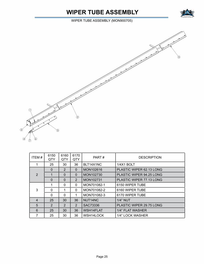
WIPER TUBE ASSEMBLY
ITEM #6150
QTY
6160
QTY
6170
QTYPART # DESCRIPTION
1 25 30 36 BLT14X1NC 1/4X1 BOLT
2
0 2 0 MON102616 PLASTIC WIPER 62.13 LONG
1 0 0 MON102730 PLASTIC WIPER 94.25 LONG
0 0 2 MON102731 PLASTIC WIPER 77.13 LONG
3
1 0 0 MON701082-1 6150 WIPER TUBE
0 1 0 MON701082-2 6160 WIPER TUBE
0 0 1 MON701082-3 6170 WIPER TUBE
4 25 30 36 NUT14NC 1/4” NUT
5 2 2 2 SAC73336 PLASTIC WIPER 29.75 LONG
6 25 30 36 WSH14FLAT 1/4” FLAT WASHER
7 25 30 36 WSH14LOCK 1/4” LOCK WASHER
WIPER TUBE ASSEMBLY (MON900705)

Page 26
ITEM # QTY PART # DESCRIPTION
1 6 BLT916X112NC 9/16X1-1/2 BOLT
2 2 MON102589 PLASTIC BUSHING (LARGE)
3 2 MON102592 PLASTIC BUSHING (SMALL)
4 2 MON701084 BEARING HOUSING
5 6 NUT916NC 9/16” NUT
6 6 WSH916LOCK 9/16” LOCK WASHER
BEARING ASSEMBLY
�
�
$
�
"
�
REEL BEARING (MON900706)
Page 27
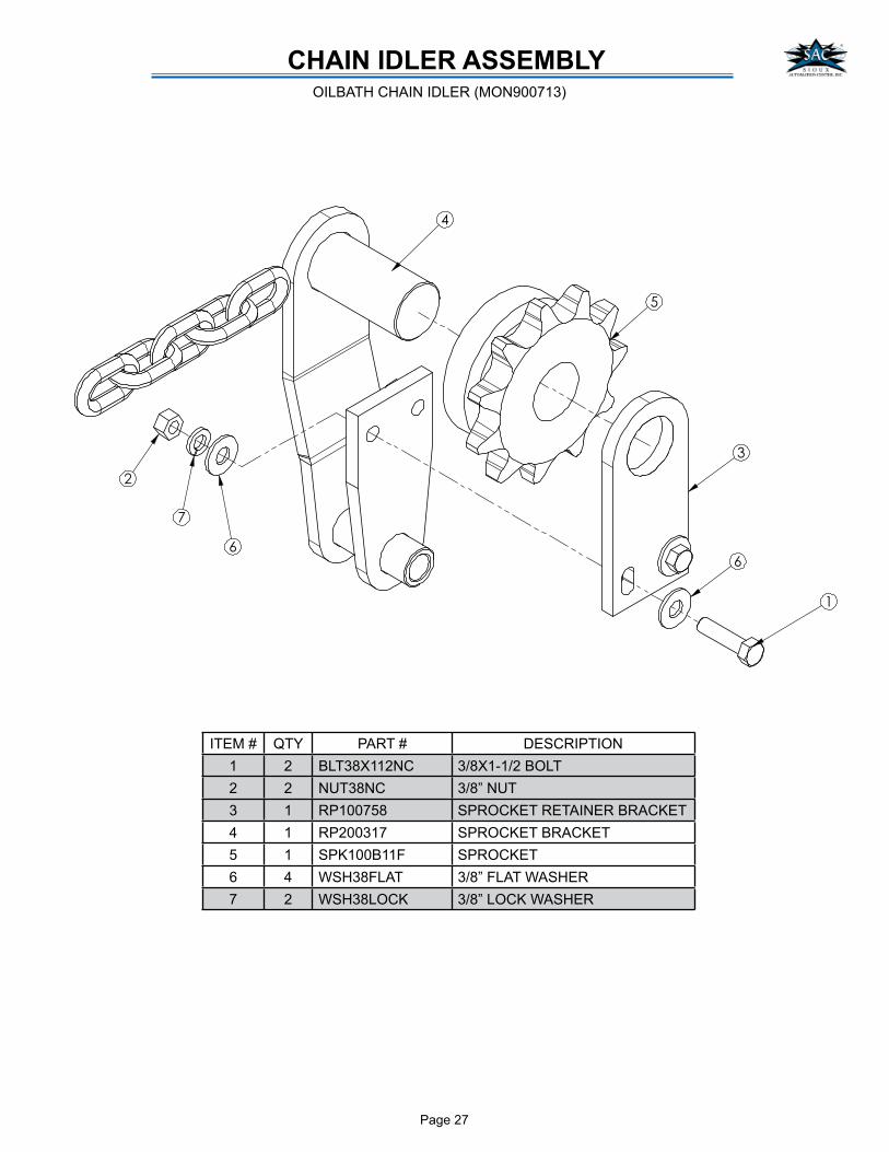
CHAIN IDLER ASSEMBLY
�
�
�
�
�
�
�
�
ITEM # QTY PART # DESCRIPTION
1 2 BLT38X112NC 3/8X1-1/2 BOLT
2 2 NUT38NC 3/8” NUT
3 1 RP100758 SPROCKET RETAINER BRACKET
4 1 RP200317 SPROCKET BRACKET
5 1 SPK100B11F SPROCKET
6 4 WSH38FLAT 3/8” FLAT WASHER
7 2 WSH38LOCK 3/8” LOCK WASHER
OILBATH CHAIN IDLER (MON900713)
Page 28
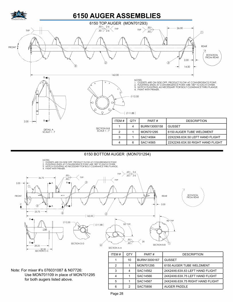
6150 AUGER ASSEMBLIES
��������
�� ��
�� ��
�����������
�������
����������
�� ��
�� ��
������
� ������������������������ ���������������������������������
� ������ ��������������������������������������������� ��� ��
� ������ ����� �������������������������������������� ���������
! ����������� ����"��
��
����� ���� ��������
���"�����
�
�
!
�
���
�
�����
#� �#
#� �#���
�� $�
� ��
�# $�
�#� ��
� ��
�
���
�
�
#
����������
��
���%
�������
ITEM # QTY PART # DESCRIPTION
1 10 BURN13000167 GUSSET
2 1 MON701295 6150 AUGER TUBE WELDMENT
3 4 SAC14562 24X24X6.63X.63 LEFT HAND FLIGHT
4 1 SAC14566 24X24X6.63X.75 LEFT HAND FLIGHT
5 1 SAC14567 24X24X6.63X.75 RIGHT HAND FLIGHT
6 2 SAC75856 AUGER PADDLE
6150 BOTTOM AUGER (MON701294)
���������
������ ����
����
���
������
��������������������������������������������������������������
�������������������������������������������� ������������������
������������������������������� �������������������������������
!�����������������"���
������
����
!
��������
���"�����
�#
�#
�
�
� ����� �
������
���� �
����
�#���
#����
!���
���������
������ ����
����
ITEM # QTY PART # DESCRIPTION
1 4 BURN13000158 GUSSET
2 1 MON701295 6150 AUGER TUBE WELDMENT
3 1 SAC14564 22X22X6.63X.50 LEFT HAND FLIGHT
4 6 SAC14565 22X22X6.63X.50 RIGHT HAND FLIGHT
6150 TOP AUGER (MON701293)
Note: For mixer #’s 076031087 & N07726:
Use MON701109 in place of MON701295
for both augers listed above.

Page 29
6160 AUGER ASSEMBLIES
������
��������� ������������ ���������������� ����������
�������������������� ���������� ��������������� �
����������������������� ��� �������� ������ �������
������������ ��� �
�
���� �
����!"
���
� �
� �
� � �!"
� �� ��
�
��
�������
� ���
�
�
�
�#����
����
�"���
��� �
�������
��������
����
�
�
��������!�
��������
�$ ��� �
�����
6160 TOP AUGER (MON701296)
ITEM # QTY PART # DESCRIPTION
1 4 BURN13000158 GUSSET
2 1 MON701298 6160 AUGER TUBE WELDMENT
3 1 SAC14564 22X22X6.63X.50 LEFT HAND FLIGHT
4 8 SAC14565 22X22X6.63X.50 RIGHT HAND FLIGHT
��������
��� �����
������
�������������������������������������������������������������
�������������������������������������������� �����������������
����������������������������������������������������������������
�����������������!���
���
�"
�"
�"����
���
������
�"�
��������
�����
���!�����
����
�
�
�
� ����
���#�
�"�#�
����
�$����
� �
�
�
�
�
���
������
����������
"$������
����������
�
$��
���
����������
�����
� ���
6160 BOTTOM AUGER (MON701297)
ITEM # QTY PART # DESCRIPTION
1 10 BURN13000167 GUSSET
2 1 MON701298 6160 AUGER TUBE WELDMENT
3 5 SAC14562 24X24X6.63X.63 LEFT HAND FLIGHT
4 1 SAC14566 24X24X6.63X.75 LEFT HAND FLIGHT
5 1 SAC14567 24X24X6.63X.75 RIGHT HAND FLIGHT
6 2 SAC75856 AUGER PADDLE
Note: For mixer #’s 075080998:
Use MON701094 in place of MON701298
for both augers listed above.
Page 30
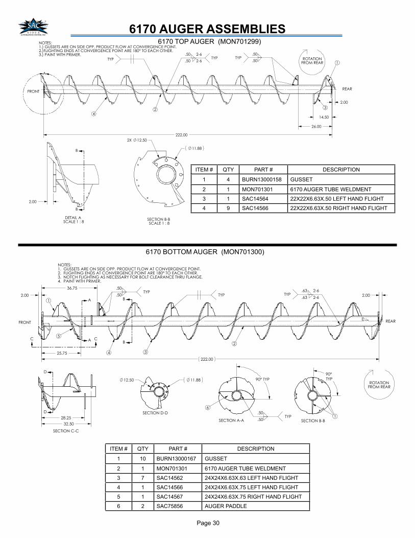
6170 AUGER ASSEMBLIES��������������� ����������������������� ��������������������������������� ����������������� ��������� ����������� ��������������
������
���
��� � !��� ������ � !
������ �
�� �
��� ����
�����
"� �
�
�!���
����
������
�"���
��� �� �� �����
����
#
#
�������# #�� �����
�����
�$ �����
6170 TOP AUGER (MON701299)
ITEM # QTY PART # DESCRIPTION
1 4 BURN13000158 GUSSET
2 1 MON701301 6170 AUGER TUBE WELDMENT
3 1 SAC14564 22X22X6.63X.50 LEFT HAND FLIGHT
4 9 SAC14566 22X22X6.63X.50 RIGHT HAND FLIGHT
��������
��� �����
������
�������������������������������������������������������������
�������������������������������������������� �����������������
����������������������������������������������������������������
�����������������!���
����"
�"
�"����
���
������ �"�
���!�����
����
��������
�����
�
�
�
�
�"�#�
����
���#�
������
����
� �
�
�
�
�
���
������
����������
"
$������
����������
�
$��
���
����������
� ���
�����
ITEM # QTY PART # DESCRIPTION
1 10 BURN13000167 GUSSET
2 1 MON701301 6170 AUGER TUBE WELDMENT
3 7 SAC14562 24X24X6.63X.63 LEFT HAND FLIGHT
4 1 SAC14566 24X24X6.63X.75 LEFT HAND FLIGHT
5 1 SAC14567 24X24X6.63X.75 RIGHT HAND FLIGHT
6 2 SAC75856 AUGER PADDLE
6170 BOTTOM AUGER (MON701300)

Page 31
NOTES

Page 32
TRAILER BASE ASSEMBLY
��
��
��
��
��
��
��
��
��
�
��
��
���� ��
��
�
��
��
��
��
TRAILER BASE ASSEMBLY (MON900709)

Page 33
ITEM # 6150
QTY.
6160
QTY.
6170
QTY.
6160
TNDM
QTY
PART # DESCRIPTION
1 4 4 4 4 BLT12X112NC 1/2X1-1/2 BOLT
2 9 9 9 9 BLT12X134NC 1/2X1-3/4 BOLT
3 2 2 2 2 BLT14X1NC 1/4X1 BOLT
4 10 10 10 10 BLT38X1NC 3/8X1 BOLT
5 4 4 4 4 BRGRCJ134 1-3/4 FLANGE BEARING
6 1 1 1 1 DEC114 DOOR GAGE DECAL
7 2 2 2 2 HUBP1134 SQUEEZE HUB
8 2 2 2 2 KEY38X2 3/8 KEY
9 2 2 2 2 MON102617 DISCHARGE SUPPORT PANEL
10 1 1 1 1 MON102713 PTO CHAIN
11
1 0 0 0 MON102716-1 6150 SHAFT
0 1 0 1 MON102716-2 6160 SHAFT
0 0 1 0 MON102716-3 6170 SHAFT
12 1 1 1 1 MON700437 INDICATOR BRACKET ASSEMBLY
13 1 1 1 1 MON701099 DISCHARGE BRACKET
14 1 1 1 1 MON701106 HYDRAULIC HOSE BRACKET
15 1 1 1 1 MON701107 DISCHARGE DOOR INDICATOR
16 1 1 1 1 MON900437 LIGHT ASSEMBLY
17
1 0 0 0 MON900703-1 6150 BOX BASE ASSEMBLY
0 1 0 1 MON900703-2 6160 BOX BASE ASSEMBLY
0 0 1 0 MON900703-3 6170 BOX BASE ASSEMBLY
18
0 0 0 1 MON900710 6160 TANDEM TRAILER ASSEMBLY
0 0 1 0 MON900720 6170 TANDEM TRAILER ASSEMBLY
1 0 0 0 MON900806 6150 TRAILER ASSEMBLY
0 1 0 0 MON900807 6160 TRAILER ASSEMBLY
19 4 4 4 4 MON900711 DUMMY SCALE KIT
20 2 2 2 2 NUT1024 10-24 NUT
21 13 13 13 13 NUT12NC 1/2” NUT
22 2 2 2 2 NUT14NC 1/4” NUT
23 10 10 10 10 NUT38NC 3/8” NUT
24 1 1 1 1 PFBL112PLUG 1-1/2” PLUG
25 2 2 2 2 PFBL2PLUG 2” PLUG
26 13 13 13 13 RC602 60-2 ROLLER CHAIN
27 1 1 1 1 RC602CON 60-2 CONECTOR LINK
28 2 2 2 2 SPASNC516X12 5/16 ALLEN SCREW
29 2 2 2 2 SPK60P18H SPROCKET
30 1 1 1 1 SPMB1024X34 10-24X3/4 BOLT
31 9 9 9 9 WSH12FLAT 1/2” FLAT WASHER
32 13 13 13 13 WSH12LOCK 1/2” LOCK WASHER
33 1 1 1 1 WSH14FLAT 1/4” FLAT WASHER
34 2 2 2 2 WSH14LOCK 1/4” LOCK WASHER
35 10 10 10 10 WSH38LOCK 3/8” LOCK WASHER
DRIVELINE ASSEMBLY
��
�����������
� �������
�
��
�
��
��
��
�
���
�
����
�
���
��

Page 34
SUBFRAME ASSEMBLY 6160 TANDEM
SUBFRAME ASSEMBLY 6170 TANDEM
�
�
�
�
��
�
��
�
�
ITEM # QTY PART # DESCRIPTION
1 2 BLT1X7NF 1X7 BOLT G8 FINE
2 1 BLT34X6NF 3/4X6 BOLT G8 FINE
3 1 MON701117 6170 TRAILER FRAME
4 1 MON800489 CAT 2 HITCH
5 1 MON800490 CAT 2 HITCH CLEVIS
6 1 MON900708 BOGIE KIT
7 2 NUT1NF 1” GRADE 8 BOLT FINE
8 1 NUT34LOCKNF 3/4” LOCK NUT GRADE 8 FINE
9 1 NUT34NF 3/4” GRADE 8 NUT FINE
10 4 TA1800X225X10HP TIRE ASSEMBLY
10A * TIR1800X225X1 TIRE
10B * RIM225X135X10HP RIM
11 2 WSH1LOCK 1” LOCK WASHER
TANDOM AXLE TRAILER (MON900710)
TANDOM AXLE TRAILER (MON900720)
� �
��
�
�
�
��
�
ITEM # QTY PART # DESCRIPTION
1 2 BLT1X7NF 1X7 BOLT G8 FINE
2 1 BLT34X6NF 3/4X6 BOLT G8 FINE
3 1 MON701097 6160 TANDEM TRAILER FRAME
4 1 MON800489 CAT 2 HITCH
5 1 MON800490 CAT 2 HITCH CLEVIS
6 1 MON900708 BOGIE KIT
7 2 NUT1NF 1” GRADE 8 BOLT FINE
8 1 NUT34LOCKNF 3/4” LOCK NUT GRADE 8 FINE
9 1 NUT34NF 3/4” GRADE 8 NUT FINE
10 4 TA1800X225X10HP TIRE ASSEMBLY
10A * TIR1800X225X1 TIRE
10B * RIM225X135X10HP RIM
11 2 WSH1LOCK 1” LOCK WASHER

Page 35
SUBFRAME ASSEMBLY 6150
SUBFRAME ASSEMBLY 6160
SINGLE AXLE TRAILER (MON900806)
SINGLE AXLE TRAILER (MON900807)
ITEM # QTY PART # DESCRIPTION
1 2 BLT1X7NF 1X7 BOLT G8 FINE
2 1 BLT34X6NF 3/4X6 BOLT G8 FINE
3 2 BLT58X7NC 5/8X7 BOLT
4 1 MON701263 6150 TRAILER FRAME
5 1 MON800489 CAT 2 HITCH
6 1 MON800490 CAT 2 HITCH CLEVIS
7 2 MON900805 10 BOLT HUB ASSEMBLY
8 2 NUT1NF 1” GRADE 8 BOLT FINE
9 1 NUT34LOCKNF 3/4” LOCK NUT GRADE 8 FINE
10 1 NUT34NF 3/4” GRADE 8 NUT FINE
11 2 NUT58LOCKNC 5/8” LOCK NUT
12 2 TA1800X225X10HP TIRE ASSEMBLY
12A * TIR1800X225X1 TIRE
12B * RIM225X135X10HP RIM
13 2 WSH1LOCK 1” LOCK WASHER
��
�
�
�
��
�
�
���
�
�
�
�
��
�
�
��
�
�
���
�
�
�
ITEM # QTY PART # DESCRIPTION
1 2 BLT1X7NF 1X7 BOLT G8 FINE
2 1 BLT34X6NF 3/4X6 BOLT G8 FINE
3 2 BLT58X7NC 5/8X7 BOLT
4 1 MON701264 6160 TRAILER FRAME
5 1 MON800489 CAT 2 HITCH
6 1 MON800490 CAT 2 HITCH CLEVIS
7 2 MON900805 10 BOLT HUB ASSEMBLY
8 2 NUT1NF 1” GRADE 8 BOLT FINE
9 1 NUT34LOCKNF 3/4” LOCK NUT GRADE 8 FINE
10 1 NUT34NF 3/4” GRADE 8 NUT FINE
11 2 NUT58LOCKNC 5/8” LOCK NUT
12 2 TA1800X225X10HP TIRE ASSEMBLY
12A * TIR1800X225X1 TIRE
12B * RIM225X135X10HP RIM
13 2 WSH1LOCK 1” LOCK WASHER
ITEM # QTY PART # DESCRIPTION
1 6 BLT516X34NC 5/16X3/4 BOLT
2 1 MON103223 SPINDLE
3 1 MON800533 10 BOLT HUB ASSEMBLY
4 1 MON800536 OIL SEAL
5 1 MON800537 DUST CAP
6 1 NUT2CSTL 2” CASTLE NUT
7 10 NUT34LUG LUG NUT
8 1 SPCP516X4 5/16X4 COTTER PIN
9 1 TIMHM212049 BEARING
10 1 TIMHM218248 BEARING
11 1 WSH2FLAT 2” FLAT WASHER
12 6 WSH516LOCK 5/16” LOCK WASHER
10 BOLT 20K HUB ASSEMBLY (MON900805)
��
���������� ������������������������������ � ������������������� � ��������������
�
�
�
���
�
�
��
!
�
REPLACEMENT BEARING RACE PART #’S ARE
TIMHM218210 (INNER) & TIMHM212011 (OUTER)
Note: For mixer #’s 076031087, N07696, N07726, &
N07739:
Use MON900808 in place of MON900805
Note: For mixer #’s 075080998, 076031099, & N07714:
Use MON900808 in place of MON900805
Page 36
�
�
�
�
��
�
�
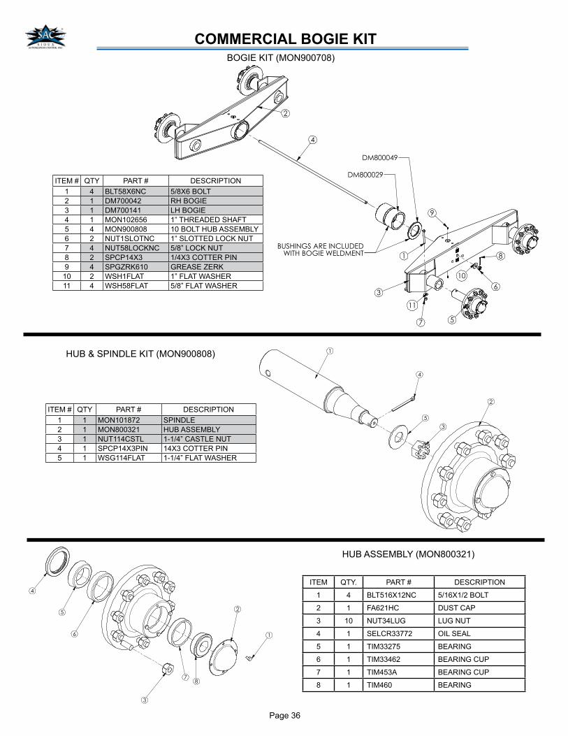
ITEM QTY. PART # DESCRIPTION
1 4 BLT516X12NC 5/16X1/2 BOLT
2 1 FA621HC DUST CAP
3 10 NUT34LUG LUG NUT
4 1 SELCR33772 OIL SEAL
5 1 TIM33275 BEARING
6 1 TIM33462 BEARING CUP
7 1 TIM453A BEARING CUP
8 1 TIM460 BEARING
��������
�
�
�
��
�
�
��
�
�
��������
��������������������
����� �������������
COMMERCIAL BOGIE KITBOGIE KIT (MON900708)
ITEM # QTY PART # DESCRIPTION
1 4 BLT58X6NC 5/8X6 BOLT
2 1 DM700042 RH BOGIE
3 1 DM700141 LH BOGIE
4 1 MON102656 1” THREADED SHAFT
5 4 MON900808 10 BOLT HUB ASSEMBLY
6 2 NUT1SLOTNC 1” SLOTTED LOCK NUT
7 4 NUT58LOCKNC 5/8” LOCK NUT
8 2 SPCP14X3 1/4X3 COTTER PIN
9 4 SPGZRK610 GREASE ZERK
10 2 WSH1FLAT 1” FLAT WASHER
11 4 WSH58FLAT 5/8” FLAT WASHER
�
�
�
�
�
ITEM # QTY PART # DESCRIPTION
1 1 MON101872 SPINDLE
2 1 MON800321 HUB ASSEMBLY
3 1 NUT114CSTL 1-1/4” CASTLE NUT
4 1 SPCP14X3PIN 14X3 COTTER PIN
5 1 WSG114FLAT 1-1/4” FLAT WASHER
HUB & SPINDLE KIT (MON900808)
HUB ASSEMBLY (MON800321)
Page 37
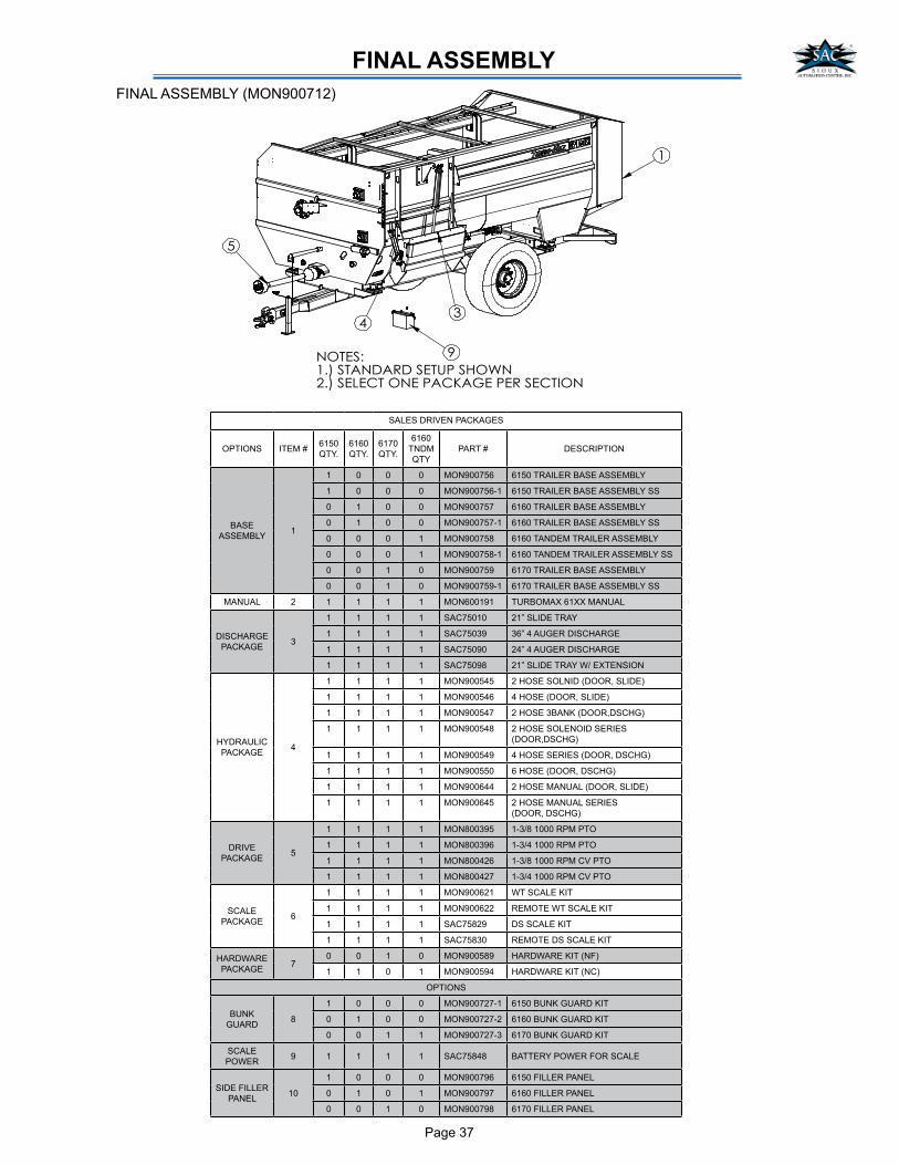
FINAL ASSEMBLY
�������������� ������������������������������� �������
�
�
�
��
SALES DRIVEN PACKAGES
OPTIONS ITEM #6150
QTY.
6160
QTY.
6170
QTY.
6160
TNDM
QTY
PART # DESCRIPTION
BASE
ASSEMBLY1
1 0 0 0 MON900756 6150 TRAILER BASE ASSEMBLY
1 0 0 0 MON900756-1 6150 TRAILER BASE ASSEMBLY SS
0 1 0 0 MON900757 6160 TRAILER BASE ASSEMBLY
0 1 0 0 MON900757-1 6160 TRAILER BASE ASSEMBLY SS
0 0 0 1 MON900758 6160 TANDEM TRAILER ASSEMBLY
0 0 0 1 MON900758-1 6160 TANDEM TRAILER ASSEMBLY SS
0 0 1 0 MON900759 6170 TRAILER BASE ASSEMBLY
0 0 1 0 MON900759-1 6170 TRAILER BASE ASSEMBLY SS
MANUAL 2 1 1 1 1 MON600191 TURBOMAX 61XX MANUAL
DISCHARGE
PACKAGE3
1 1 1 1 SAC75010 21” SLIDE TRAY
1 1 1 1 SAC75039 36” 4 AUGER DISCHARGE
1 1 1 1 SAC75090 24” 4 AUGER DISCHARGE
1 1 1 1 SAC75098 21” SLIDE TRAY W/ EXTENSION
HYDRAULIC
PACKAGE4
1 1 1 1 MON900545 2 HOSE SOLNID (DOOR, SLIDE)
1 1 1 1 MON900546 4 HOSE (DOOR, SLIDE)
1 1 1 1 MON900547 2 HOSE 3BANK (DOOR,DSCHG)
1 1 1 1 MON900548 2 HOSE SOLENOID SERIES
(DOOR,DSCHG)
1 1 1 1 MON900549 4 HOSE SERIES (DOOR, DSCHG)
1 1 1 1 MON900550 6 HOSE (DOOR, DSCHG)
1 1 1 1 MON900644 2 HOSE MANUAL (DOOR, SLIDE)
1 1 1 1 MON900645 2 HOSE MANUAL SERIES
(DOOR, DSCHG)
DRIVE
PACKAGE5
1 1 1 1 MON800395 1-3/8 1000 RPM PTO
1 1 1 1 MON800396 1-3/4 1000 RPM PTO
1 1 1 1 MON800426 1-3/8 1000 RPM CV PTO
1 1 1 1 MON800427 1-3/4 1000 RPM CV PTO
SCALE
PACKAGE6
1 1 1 1 MON900621 WT SCALE KIT
1 1 1 1 MON900622 REMOTE WT SCALE KIT
1 1 1 1 SAC75829 DS SCALE KIT
1 1 1 1 SAC75830 REMOTE DS SCALE KIT
HARDWARE
PACKAGE7
0 0 1 0 MON900589 HARDWARE KIT (NF)
1 1 0 1 MON900594 HARDWARE KIT (NC)
OPTIONS
BUNK
GUARD8
1 0 0 0 MON900727-1 6150 BUNK GUARD KIT
0 1 0 0 MON900727-2 6160 BUNK GUARD KIT
0 0 1 1 MON900727-3 6170 BUNK GUARD KIT
SCALE
POWER9 1 1 1 1 SAC75848 BATTERY POWER FOR SCALE
SIDE FILLER
PANEL10
1 0 0 0 MON900796 6150 FILLER PANEL
0 1 0 1 MON900797 6160 FILLER PANEL
0 0 1 0 MON900798 6170 FILLER PANEL
FINAL ASSEMBLY (MON900712)
Page 38
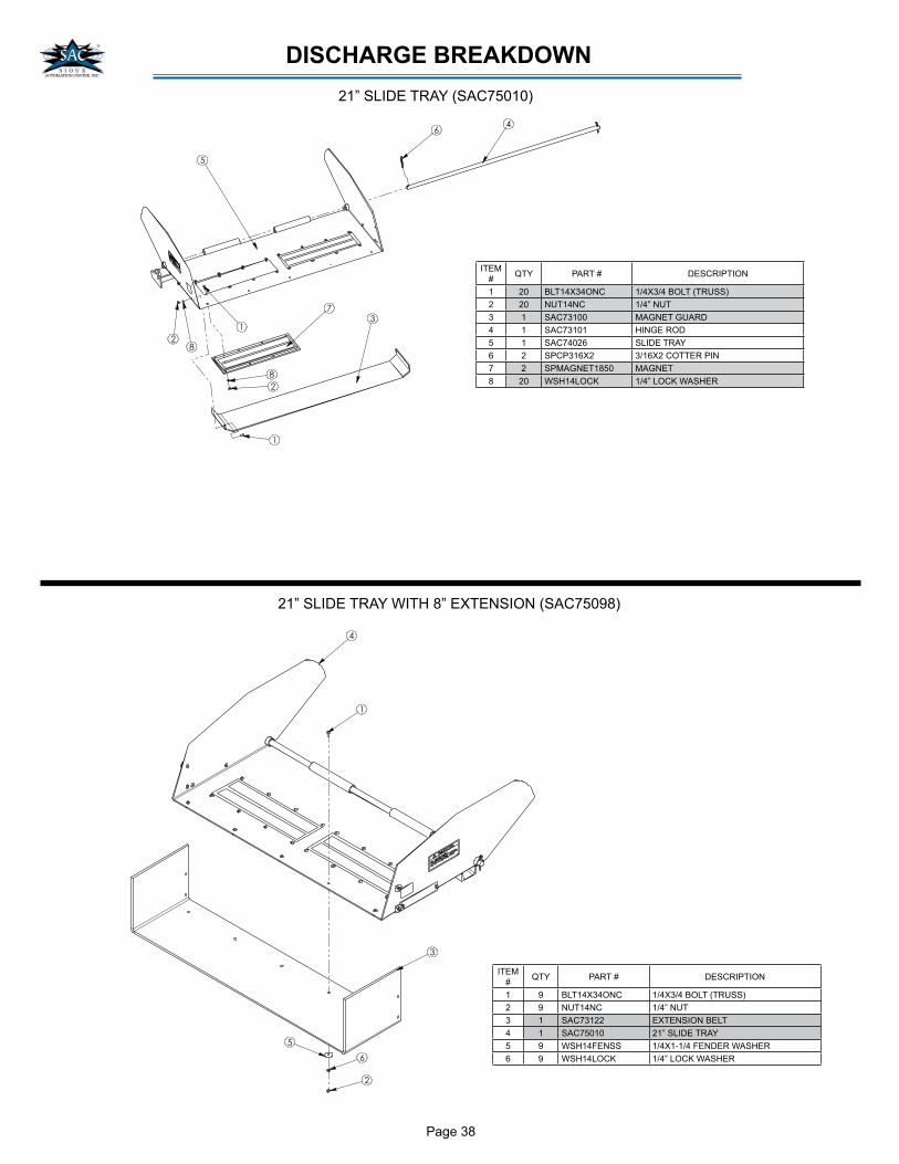
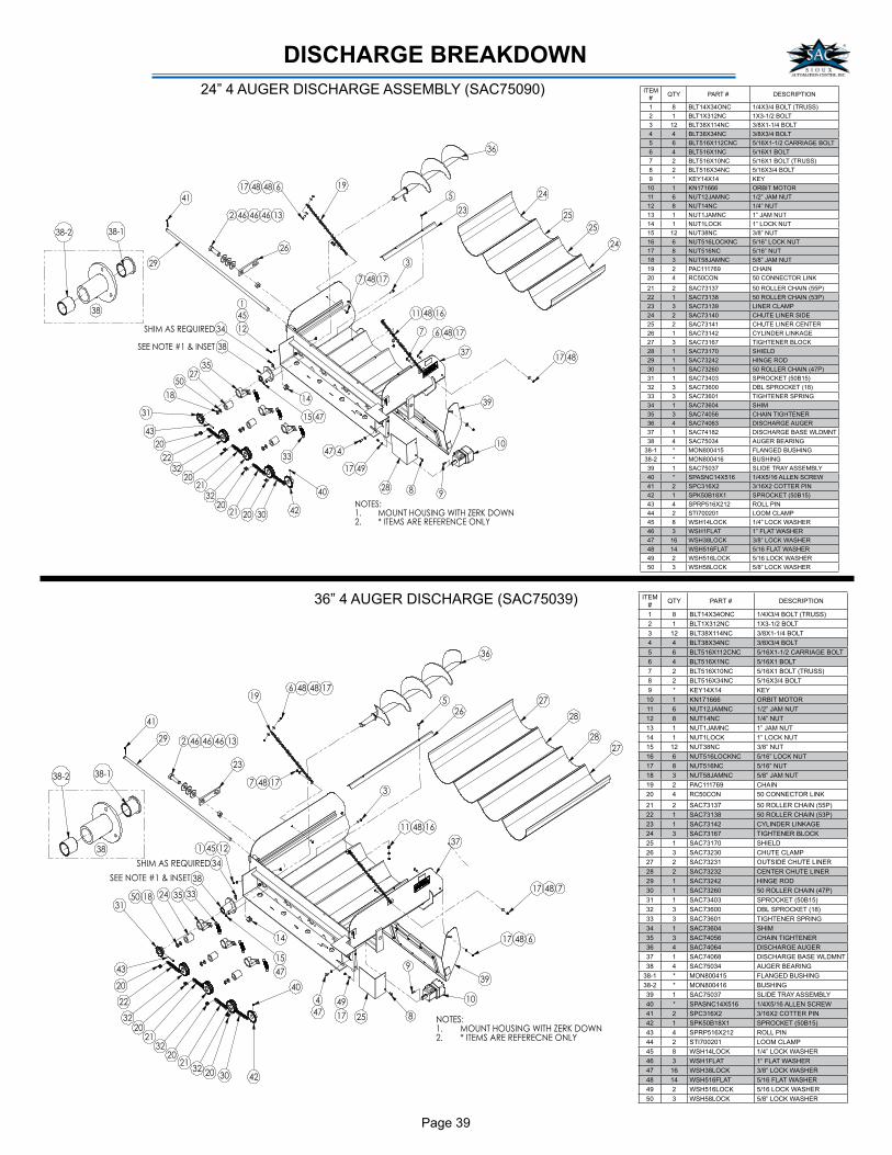
DISCHARGE BREAKDOWN
64
28
1
5
7
8
2
3
1
ITEM
#QTY PART # DESCRIPTION
1 20 BLT14X34ONC 1/4X3/4 BOLT (TRUSS)
2 20 NUT14NC 1/4” NUT
3 1 SAC73100 MAGNET GUARD
4 1 SAC73101 HINGE ROD
5 1 SAC74026 SLIDE TRAY
6 2 SPCP316X2 3/16X2 COTTER PIN
7 2 SPMAGNET1850 MAGNET
8 20 WSH14LOCK 1/4” LOCK WASHER
21” SLIDE TRAY (SAC75010)
ITEM
#QTY PART # DESCRIPTION
1 9 BLT14X34ONC 1/4X3/4 BOLT (TRUSS)
2 9 NUT14NC 1/4” NUT
3 1 SAC73122 EXTENSION BELT
4 1 SAC75010 21” SLIDE TRAY
5 9 WSH14FENSS 1/4X1-1/4 FENDER WASHER
6 9 WSH14LOCK 1/4” LOCK WASHER
21” SLIDE TRAY WITH 8” EXTENSION (SAC75098)
1
4
3
6
2
5
Page 39
DISCHARGE BREAKDOWN
��
��
�� ��
��
��
��
��
��
��
����
��
�
�� ��
��
�� �
�
��
��
��
�� ���
�
��
���
��
��
�
��
� ��
�
� �
�
��
�
����
�� �
��
��
��
��
�
��
�
�� ��������� ��� ��
��
��
��
��
��
��
����
��
��
�
��
�
�������������� ����
��
���� ����
������
������������ ���� ������ ������!
��"� �����������#����$����%&�!
ITEM
#QTY PART # DESCRIPTION
1 8 BLT14X34ONC 1/4X3/4 BOLT (TRUSS)
2 1 BLT1X312NC 1X3-1/2 BOLT
3 12 BLT38X114NC 3/8X1-1/4 BOLT
4 4 BLT38X34NC 3/8X3/4 BOLT
5 6 BLT516X112CNC 5/16X1-1/2 CARRIAGE BOLT
6 4 BLT516X1NC 5/16X1 BOLT
7 2 BLT516X10NC 5/16X1 BOLT (TRUSS)
8 2 BLT516X34NC 5/16X3/4 BOLT
9 * KEY14X14 KEY
10 1 KN171666 ORBIT MOTOR
11 6 NUT12JAMNC 1/2” JAM NUT
12 8 NUT14NC 1/4” NUT
13 1 NUT1JAMNC 1” JAM NUT
14 1 NUT1LOCK 1” LOCK NUT
15 12 NUT38NC 3/8” NUT
16 6 NUT516LOCKNC 5/16” LOCK NUT
17 8 NUT516NC 5/16” NUT
18 3 NUT58JAMNC 5/8” JAM NUT
19 2 PAC111769 CHAIN
20 4 RC50CON 50 CONNECTOR LINK
21 2 SAC73137 50 ROLLER CHAIN (55P)
22 1 SAC73138 50 ROLLER CHAIN (53P)
23 3 SAC73139 LINER CLAMP
24 2 SAC73140 CHUTE LINER SIDE
25 2 SAC73141 CHUTE LINER CENTER
26 1 SAC73142 CYLINDER LINKAGE
27 3 SAC73167 TIGHTENER BLOCK
28 1 SAC73170 SHIELD
29 1 SAC73242 HINGE ROD
30 1 SAC73260 50 ROLLER CHAIN (47P)
31 1 SAC73403 SPROCKET (50B15)
32 3 SAC73600 DBL SPROCKET (18)
33 3 SAC73601 TIGHTENER SPRING
34 1 SAC73604 SHIM
35 3 SAC74056 CHAIN TIGHTENER
36 4 SAC74063 DISCHARGE AUGER
37 1 SAC74182 DISCHARGE BASE WLDMNT
38 4 SAC75034 AUGER BEARING
38-1 * MON800415 FLANGED BUSHING
38-2 * MON800416 BUSHING
39 1 SAC75037 SLIDE TRAY ASSEMBLY
40 * SPASNC14X516 1/4X5/16 ALLEN SCREW
41 2 SPC316X2 3/16X2 COTTER PIN
42 1 SPK50B18X1 SPROCKET (50B15)
43 4 SPRP516X212 ROLL PIN
44 2 STI700201 LOOM CLAMP
45 8 WSH14LOCK 1/4” LOCK WASHER
46 3 WSH1FLAT 1” FLAT WASHER
47 16 WSH38LOCK 3/8” LOCK WASHER
48 14 WSH516FLAT 5/16 FLAT WASHER
49 2 WSH516LOCK 5/16 LOCK WASHER
50 3 WSH58LOCK 5/8” LOCK WASHER
24” 4 AUGER DISCHARGE ASSEMBLY (SAC75090)
��
�����������������
�� � ��
������
�������������������������������
������������������������������
!�"
��
�#
"
!
�!
��
��
�!
"
#�$
�#
#
#
��
�
� �
�
!
�!
#
�
!
#
�
�
!
!
�! #
�!
�$
%
$
�!
$
"
�
����������&������
�
��
���"� �"%�
�
%
��
�%
��
�
��
�%
��%
�% �%
$
36” 4 AUGER DISCHARGE (SAC75039) ITEM
#QTY PART # DESCRIPTION
1 8 BLT14X34ONC 1/4X3/4 BOLT (TRUSS)
2 1 BLT1X312NC 1X3-1/2 BOLT
3 12 BLT38X114NC 3/8X1-1/4 BOLT
4 4 BLT38X34NC 3/8X3/4 BOLT
5 6 BLT516X112CNC 5/16X1-1/2 CARRIAGE BOLT
6 4 BLT516X1NC 5/16X1 BOLT
7 2 BLT516X10NC 5/16X1 BOLT (TRUSS)
8 2 BLT516X34NC 5/16X3/4 BOLT
9 * KEY14X14 KEY
10 1 KN171666 ORBIT MOTOR
11 6 NUT12JAMNC 1/2” JAM NUT
12 8 NUT14NC 1/4” NUT
13 1 NUT1JAMNC 1” JAM NUT
14 1 NUT1LOCK 1” LOCK NUT
15 12 NUT38NC 3/8” NUT
16 6 NUT516LOCKNC 5/16” LOCK NUT
17 8 NUT516NC 5/16” NUT
18 3 NUT58JAMNC 5/8” JAM NUT
19 2 PAC111769 CHAIN
20 4 RC50CON 50 CONNECTOR LINK
21 2 SAC73137 50 ROLLER CHAIN (55P)
22 1 SAC73138 50 ROLLER CHAIN (53P)
23 1 SAC73142 CYLINDER LINKAGE
24 3 SAC73167 TIGHTENER BLOCK
25 1 SAC73170 SHIELD
26 3 SAC73230 CHUTE CLAMP
27 2 SAC73231 OUTSIDE CHUTE LINER
28 2 SAC73232 CENTER CHUTE LINER
29 1 SAC73242 HINGE ROD
30 1 SAC73260 50 ROLLER CHAIN (47P)
31 1 SAC73403 SPROCKET (50B15)
32 3 SAC73600 DBL SPROCKET (18)
33 3 SAC73601 TIGHTENER SPRING
34 1 SAC73604 SHIM
35 3 SAC74056 CHAIN TIGHTENER
36 4 SAC74064 DISCHARGE AUGER
37 1 SAC74068 DISCHARGE BASE WLDMNT
38 4 SAC75034 AUGER BEARING
38-1 * MON800415 FLANGED BUSHING
38-2 * MON800416 BUSHING
39 1 SAC75037 SLIDE TRAY ASSEMBLY
40 * SPASNC14X516 1/4X5/16 ALLEN SCREW
41 2 SPC316X2 3/16X2 COTTER PIN
42 1 SPK50B18X1 SPROCKET (50B15)
43 4 SPRP516X212 ROLL PIN
44 2 STI700201 LOOM CLAMP
45 8 WSH14LOCK 1/4” LOCK WASHER
46 3 WSH1FLAT 1” FLAT WASHER
47 16 WSH38LOCK 3/8” LOCK WASHER
48 14 WSH516FLAT 5/16 FLAT WASHER
49 2 WSH516LOCK 5/16 LOCK WASHER
50 3 WSH58LOCK 5/8” LOCK WASHER
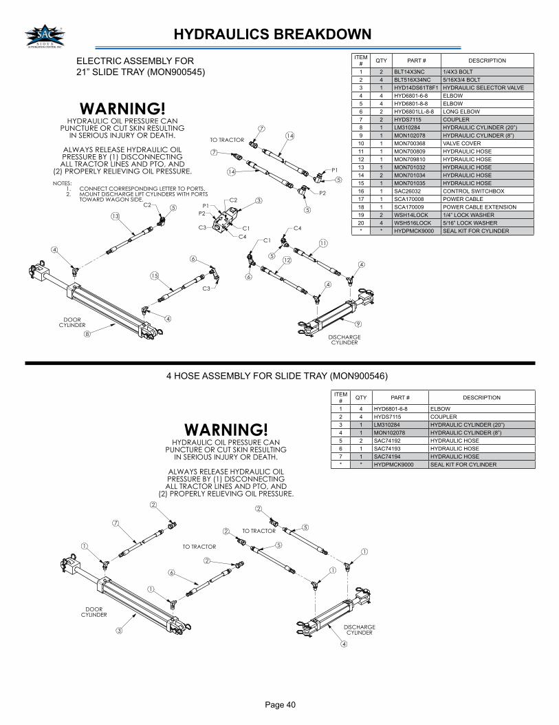
Page 40
HYDRAULICS BREAKDOWN
4
12
11
4
4
WARNING!HYDRAULIC OIL PRESSURE CAN
PUNCTURE OR CUT SKIN RESULTINGIN SERIOUS INJURY OR DEATH.
ALWAYS RELEASE HYDRAULIC OILPRESSURE BY (1) DISCONNECTINGALL TRACTOR LINES AND PTO, AND
(2) PROPERLY RELIEVING OIL PRESSURE.
15
49
DISCHARGECYLINDER
13
3
7
7
8
DOORCYLINDER
TO TRACTOR14
14 P1
P2
C3
C2
C1
C4
6
65
5
5
5P1
P2
C3
C4
C1
C2
NOTES:CONNECT CORRESPONDING LETTER TO PORTS.1.MOUNT DISCHARGE LIFT CYLINDERS WITH PORTS 2.TOWARD WAGON SIDE.
ITEM
#QTY PART # DESCRIPTION
1 2 BLT14X3NC 1/4X3 BOLT
2 4 BLT516X34NC 5/16X3/4 BOLT
3 1 HYD14DS61T8F1 HYDRAULIC SELECTOR VALVE
4 4 HYD6801-6-8 ELBOW
5 4 HYD6801-8-8 ELBOW
6 2 HYD6801LL-8-8 LONG ELBOW
7 2 HYDS7115 COUPLER
8 1 LM310284 HYDRAULIC CYLINDER (20”)
9 1 MON102078 HYDRAULIC CYLINDER (8”)
10 1 MON700368 VALVE COVER
11 1 MON700809 HYDRAULIC HOSE
12 1 MON709810 HYDRAULIC HOSE
13 1 MON701032 HYDRAULIC HOSE
14 2 MON701034 HYDRAULIC HOSE
15 1 MON701035 HYDRAULIC HOSE
16 1 SAC26032 CONTROL SWITCHBOX
17 1 SCA170008 POWER CABLE
18 1 SCA170009 POWER CABLE EXTENSION
19 2 WSH14LOCK 1/4” LOCK WASHER
20 4 WSH516LOCK 5/16” LOCK WASHER
* * HYDPMCK9000 SEAL KIT FOR CYLINDER
ELECTRIC ASSEMBLY FOR
21” SLIDE TRAY (MON900545)
ITEM
#QTY PART # DESCRIPTION
1 4 HYD6801-6-8 ELBOW
2 4 HYDS7115 COUPLER
3 1 LM310284 HYDRAULIC CYLINDER (20”)
4 1 MON102078 HYDRAULIC CYLINDER (8”)
5 2 SAC74192 HYDRAULIC HOSE
6 1 SAC74193 HYDRAULIC HOSE
7 1 SAC74194 HYDRAULIC HOSE
* * HYDPMCK9000 SEAL KIT FOR CYLINDER
4 HOSE ASSEMBLY FOR SLIDE TRAY (MON900546)
7
5
5
WARNING!HYDRAULIC OIL PRESSURE CAN
PUNCTURE OR CUT SKIN RESULTINGIN SERIOUS INJURY OR DEATH.
ALWAYS RELEASE HYDRAULIC OILPRESSURE BY (1) DISCONNECTINGALL TRACTOR LINES AND PTO, AND
(2) PROPERLY RELIEVING OIL PRESSURE.
6
DISCHARGECYLINDER
2
2
2
2
DOORCYLINDER
1
1
1
1TO TRACTOR
TO TRACTOR
3
4

Page 41
HYDRAULICS BREAKDOWN
6
17
16
WARNING!HYDRAULIC OIL PRESSURE CAN
PUNCTURE OR CUT SKIN RESULTINGIN SERIOUS INJURY OR DEATH.
ALWAYS RELEASE HYDRAULIC OILPRESSURE BY (1) DISCONNECTINGALL TRACTOR LINES AND PTO, AND
(2) PROPERLY RELIEVING OIL PRESSURE.
21
DISCHARGECYLINDER
18
14
10
10
DOORCYLINDER
TO TRACTOR20
20
C - TANK
D - PRESSURE
E
F
I
J
4
4
4
5
5D
C
GH
EF
NOTES:CONNECT CORRESPONDING LETTER TO PORTS.1.MOUNT DISCHARGE LIFT CYLINDERS WITH PORTS 2.TOWARD WAGON SIDE.
IJ
9
4
19
4
19
G
H 3
9
3
6
11 23
6
6
7
8
ITEM
#QTY PART # DESCRIPTION
1 4 BLT516X1NC 5/16X1 BOLT
2 4 BLT516X34NC 5/16X3/4 BOLT
3 2 HYD6400-8-10 REDUCER ADAPTER
4 6 HYD6400-8-8 ADAPTER
5 2 HYD6500-8-8 ELBOW
6 4 HYD6801-6-8 REDUCER ELBOW
7 1 HYD6801-8-10 REDUCER ELBOW
8 1 HYD6801LL-8-10 LONG LEG REUDCER ELBOW
9 2 HYDFC10 CHECK VALVE
10 2 HYDS7115 COUPLER
11 1 LM310284 HYDRAULIC CYLINDER (20”)
12 1 MON102020 VALVE COVER
13 1 MON700368 3 BANK VALVE COVER
14 1 MON700563 3 BANK VALVE
15 1 MON700564 3 BANK CONTROL BOX
16 1 MON700809 HYDRAULIC HOSE
17 1 MON700810 HYDRAULIC HOSE
18 1 MON701032 HYDRAULIC HOSE
19 2 MON701033 HYDRAULIC HOSE
20 2 MON701034 HYDRAULIC HOSE
21 1 MON701035 HYDRAULIC HOSE
22 8 NUT516NC 5/16” NUT
23 1 SAC73594 HYDRAULIC CYLINDER (18”)
24 1 SCA170009 POWER CABLE EXTENSION
25 1 SCA170071 POWER CABLE
26 8 WSH516FLAT 5/16” FLAT WASHER
27 8 WSH516LOCK 5/16” LOCK WASHER
* * HYDPMCK9000 SEAL KIT FOR CYLINDER
3 BANK VALVE ASSEMBLY FOR POWER DISCHARGE (MON900547)
21
WARNING!HYDRAULIC OIL PRESSURE CAN
PUNCTURE OR CUT SKIN RESULTINGIN SERIOUS INJURY OR DEATH.
ALWAYS RELEASE HYDRAULIC OILPRESSURE BY (1) DISCONNECTINGALL TRACTOR LINES AND PTO, AND
(2) PROPERLY RELIEVING OIL PRESSURE.
17
DISCHARGECYLINDER
14 3
11
11
DOORCYLINDER
TO TRACTOR
16
P1
P2
C3
C2
C1
C4
9
9
7
7
7
P1
P2
C3
C4
C1
C2
NOTES:CONNECT CORRESPONDING LETTER TO PORTS.1.MOUNT DISCHARGE LIFT CYLINDERS WITH PORTS 2.TOWARD WAGON SIDE.
7
15
46
10
8
4
C5
C6
C6
C5
16
5
55
5
20
12 19
15
ELECTRIC SELECTOR VALVE WITH SERIES PLUMBED POWER DISCHARGE (MON900548)
ITEM
#QTY PART # DESCRIPTION
1 2 BLT14X3NC 1/4X3 BOLT
2 4 BLT516X34NC 5/16X3/4 BOLT
3 1 HYD14DS61T8F1 SELECTOR VALVE
4 2 HYD6602-8-8-8 ADAPTER TEE
5 4 HYD6801-6-8 REDUCER ELBOW
6 1 HYD6801-8-10 REDUCER ELBOW
7 4 HYD6801-8-8 ELBOW
8 1 HYD6801LL-8-10 LONG LEG REUDCER ELBOW
9 2 HYD6801LL-8-8 LONG LEG ELBOW
10 1 HYDFC10 CHECK VALVE
11 2 HYDS7115 COUPLER
12 1 LM310284 HYDRAULIC CYLINDER (20”)
13 1 MON700368 3 BANK VALVE COVER
14 1 MON701032 HYDRAULIC HOSE
15 2 MON701033 HYDRAULIC HOSE
16 2 MON701034 HYDRAULIC HOSE
17 1 MON701035 HYDRAULIC HOSE
18 1 SAC26032 SOLENOID CONTROL BOX
19 1 SAC73594 HYDRAULIC CYLINDER (18”)
20 1 SAC74195 HYDRAULIC HOSE
21 1 SAC74197 HYDRAULIC HOSE
22 1 SCA170009 POWER CABLE EXTENSION
23 1 SCA170071 POWER CABLE
24 2 WSH14LOCK 1/4” LOCK WASHER
25 4 WSH516LOCK 5/16” LOCK WASHER
* * HYDPMCK9000 SEAL KIT FOR CYLINDER
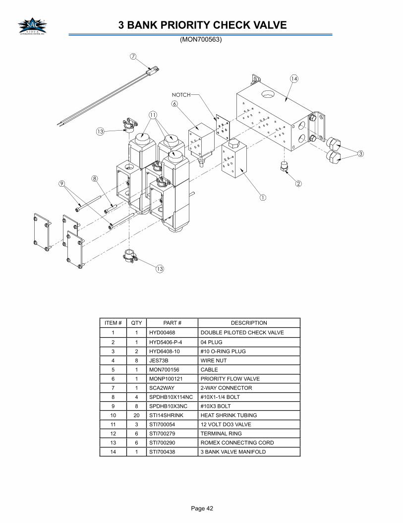
Page 42
�
��
�
��
�
�
��
!
��
"
����
3 BANK PRIORITY CHECK VALVE
(MON700563)
ITEM # QTY PART # DESCRIPTION
1 1 HYD00468 DOUBLE PILOTED CHECK VALVE
2 1 HYD5406-P-4 04 PLUG
3 2 HYD6408-10 #10 O-RING PLUG
4 8 JES73B WIRE NUT
5 1 MON700156 CABLE
6 1 MONP100121 PRIORITY FLOW VALVE
7 1 SCA2WAY 2-WAY CONNECTOR
8 4 SPDHB10X114NC #10X1-1/4 BOLT
9 8 SPDHB10X3NC #10X3 BOLT
10 20 STI14SHRINK HEAT SHRINK TUBING
11 3 STI700054 12 VOLT DO3 VALVE
12 6 STI700279 TERMINAL RING
13 6 STI700290 ROMEX CONNECTING CORD
14 1 STI700438 3 BANK VALVE MANIFOLD

Page 43
HYDRAULICS BREAKDOWN
2
2
2
WARNING!HYDRAULIC OIL PRESSURE CAN
PUNCTURE OR CUT SKIN RESULTINGIN SERIOUS INJURY OR DEATH.
ALWAYS RELEASE HYDRAULIC OILPRESSURE BY (1) DISCONNECTINGALL TRACTOR LINES AND PTO, AND
(2) PROPERLY RELIEVING OIL PRESSURE.
2
DISCHARGECYLINDER
DOORCYLINDER
TO TRACTOR
NOTES:CONNECT CORRESPONDING LETTER TO PORTS.1.MOUNT DISCHARGE LIFT CYLINDERS WITH PORTS 2.TOWARD WAGON SIDE.
8
8
5
A
B
B
A
9
7
11
10
6
612
13
6
6 TO TRACTOR
1
1
3
4
ITEM
#QTY PART # DESCRIPTION
1 2 HYD6602-8-8-8 ADAPTER TEE
2 4 HYD6801-6-8 REDUCER ELBOW
3 1 HYD6801-8-10 REDUCER ELBOW
4 1 HYD6801LL-8-10 LONG LEG REDUCER ELBOW
5 1 HYDFC10 CHECK VALVE
6 4 HYDS7115 COUPLER
7 1 LM310284 HYDRAULIC CYLINDER (20”)
8 2 MON700717 HYDRAULIC HOSE
9 1 SAC73594 HYDRAULIC CYLINDER (18”)
10 1 SAC74193 HYDRAULIC HOSE
11 1 SAC74194 HYDRAULIC HOSE
12 1 SAC74195 HYDRAULIC HOSE
13 1 SAC74197 HYDRAULIC HOSE
* * HYDPMCK9000 SEAL KIT FOR CYLINDER
4 HOSE ASSEMBLY (MON900549)
WARNING!HYDRAULIC OIL PRESSURE CAN
PUNCTURE OR CUT SKIN RESULTINGIN SERIOUS INJURY OR DEATH.
ALWAYS RELEASE HYDRAULIC OILPRESSURE BY (1) DISCONNECTINGALL TRACTOR LINES AND PTO, AND
(2) PROPERLY RELIEVING OIL PRESSURE.
DISCHARGECYLINDER
DOORCYLINDER
11
TO TRACTOR
NOTES:MOUNT DISCHARGE LIFT CYLINDERS WITH PORTS 1.TOWARD WAGON SIDE.
5
5
1
10
5
1
59
1
1
12
5
6
8
TO TRACTOR
TO TRACTOR
5
7
7
3
2
4
6 HOSE ASSEMBLY (MON900550)
ITEM
#QTY PART # DESCRIPTION
1 4 HYD6801-6-8 REDUCER ELBOW
2 1 HYD6801-8-10 REDUCER ELBOW
3 1 HYD6801LL-8-10 LONG LEG REDUCER ELBOW
4 1 HYDFC10 CHECK VALVE
5 6 HYDS7115 COUPLER
6 1 LM310284 HYDRAULIC CYLINDER (20”)
7 2 MON700717 HYDRAULIC HOSE
8 1 SAC73594 HYDRAULIC CYLINDER (18”)
9 1 SAC74192 HYDRAULIC HOSE
10 1 SAC74193 HYDRAULIC HOSE
11 1 SAC74194 HYDRAULIC HOSE
12 1 SAC74209 HYDRAULIC HOSE
* * HYDPMCK9000 SEAL KIT FOR CYLINDER

Page 44
CONTROL BOX BREAKDOWN
ITEM
#QTY PART # DESCRIPTION
1 1 MON101048 FACE PLATE
2 1 SCASPSTSC SWITCH (ON/OFF)
3 2 SCASPDTMOM SWITCH (MOMENTARY)
4 1 SCASPDT1/2MOM SWITCH (1/2 MOMENTARY)
5 13 JES461065 RING TERMINAL
6 1 SCA345913 FUSE HOLDER
7 1 JES3AG5A 5 AMP 1/4 X 1-1/4 FUSE
8 1 SCA2060611 11-4 RECEPTICAL
9 10 SCA660994 18-16 GOLD CONTACT PIN
10 1 SCA2067051 13-9 RECEPTICAL
11 8 SPMB440X12 4-40 1/2” MACHINE BOLT
12 1 SCAHOFA604LP CONTROL BOX
13 4 SPMB832X38 8-32X3/8 MACHINE BOLT
14 4 NUT832 8-32 NUT
15 2 SCADFL30 FLANGE MAGNET
16 6 STI1812CNTRL CONTROL CABLE
17 1 SCAECG572 DIODE
18 4 STI\700155 RUBBER BOOT
19 1 SCA2064031 CONNECTOR
20 1 SCA2064034 CONNECTOR
21 8 NUT440 4-40 NUT
3 BANK CONTROL BOX (MON700564)
ELECTRICAL SELECTOR CONTROL BOX (SAC26032)
ITEM
#QTY PART # DESCRIPTION
1 1 HYDO212291100 DIN CONNECTOR
2 1 JES3AG10A 10 AMP 1/4 X 1-1/4 FUSE
3 1 SAC60514 FACE PLATE
4 6 SCA14SHRINK 1/4 SHRINK TUBING
5 5 SCA18SHRINK 1/8 SHRINK TUBING
6 2 SCA2WAY 2 WAY CONNECTOR
7 1 SCA345913 FUSE HOLDER
8 8 SCA38SHRINK 3/8 SHRINK TUBING
9 2 STI701353 CABLE NUT
10 96 SCACORD182SJ 2 WIRE CORD
11 240 SCACORD183SJ 3 WIRE CORD
12 1 SCAPVC4X4X2 CONTROL BOX
13 1 SCAPSTSO TOGGLE SWITCH
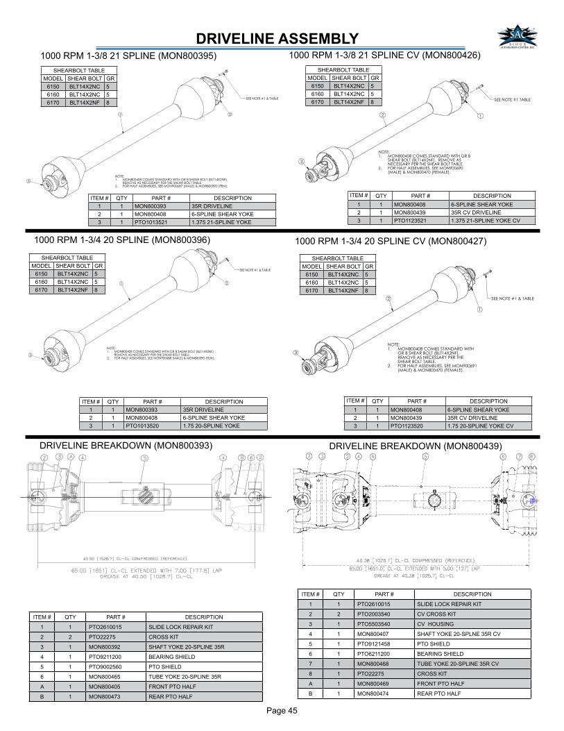
Page 45
DRIVELINE ASSEMBLY
3
SEE NOTE #1 & TABLE
NOTE: MON800408 COMES STANDARD WITH GR 8 SHEAR BOLT (BLT14X2NF). 1.REMOVE AS NECESSARY PER THE SHEAR BOLT TABLE.FOR HALF ASSEMBLIES, SEE MON900687 (MALE) & MON800390 (FEM).2.
21
ITEM # QTY PART # DESCRIPTION
1 1 PTO2610015 SLIDE LOCK REPAIR KIT
2 2 PTO22275 CROSS KIT
3 1 MON800392 SHAFT YOKE 20-SPLINE 35R
4 1 PTO9211200 BEARING SHIELD
5 1 PTO9002560 PTO SHIELD
6 1 MON800465 TUBE YOKE 20-SPLINE 35R
A 1 MON800405 FRONT PTO HALF
B 1 MON800473 REAR PTO HALF
SHEARBOLT TABLE
MODEL SHEAR BOLT GR
6150 BLT14X2NC 5
6160 BLT14X2NC 5
6170 BLT14X2NF 8
SHEARBOLT TABLE
MODEL SHEAR BOLT GR
6150 BLT14X2NC 5
6160 BLT14X2NC 5
6170 BLT14X2NF 8
ITEM # QTY PART # DESCRIPTION
1 1 MON800393 35R DRIVELINE
2 1 MON800408 6-SPLINE SHEAR YOKE
3 1 PTO1013520 1.75 20-SPLINE YOKE
ITEM # QTY PART # DESCRIPTION
1 1 MON800393 35R DRIVELINE
2 1 MON800408 6-SPLINE SHEAR YOKE
3 1 PTO1013521 1.375 21-SPLINE YOKE
1000 RPM 1-3/8 21 SPLINE (MON800395) 1000 RPM 1-3/8 21 SPLINE CV (MON800426)
ITEM # QTY PART # DESCRIPTION
1 1 MON800408 6-SPLINE SHEAR YOKE
2 1 MON800439 35R CV DRIVELINE
3 1 PTO1123521 1.375 21-SPLINE YOKE CV
1000 RPM 1-3/4 20 SPLINE (MON800396)
1
3
SEE NOTE #1 & TABLE
2
NOTE: MON800408 COMES STANDARD WITH GR 8 SHEAR BOLT (BLT14X2NF). 1.REMOVE AS NECESSARY PER THE SHEAR BOLT TABLE.FOR HALF ASSEMBLIES, SEE MON900688 (MALE) & MON800390 (FEM).2.
SHEARBOLT TABLE
MODEL SHEAR BOLT GR
6150 BLT14X2NC 5
6160 BLT14X2NC 5
6170 BLT14X2NF 8
SHEARBOLT TABLE
MODEL SHEAR BOLT GR
6150 BLT14X2NC 5
6160 BLT14X2NC 5
6170 BLT14X2NF 8
1000 RPM 1-3/4 20 SPLINE CV (MON800427)
ITEM # QTY PART # DESCRIPTION
1 1 MON800408 6-SPLINE SHEAR YOKE
2 1 MON800439 35R CV DRIVELINE
3 1 PTO1123520 1.75 20-SPLINE YOKE CV
DRIVELINE BREAKDOWN (MON800393) DRIVELINE BREAKDOWN (MON800439)
ITEM # QTY PART # DESCRIPTION
1 1 PTO2610015 SLIDE LOCK REPAIR KIT
2 2 PTO2003540 CV CROSS KIT
3 1 PTO5503540 CV HOUSING
4 1 MON800407 SHAFT YOKE 20-SPLNE 35R CV
5 1 PTO9121458 PTO SHIELD
6 1 PTO6211200 BEARING SHIELD
7 1 MON800468 TUBE YOKE 20-SPLINE 35R CV
8 1 PTO22275 CROSS KIT
A 1 MON800469 FRONT PTO HALF
B 1 MON800474 REAR PTO HALF
2
3
NOTE: MON800408 COMES STANDARD WITH GR 81.SHEAR BOLT (BLT14X2NF). REMOVE ASNECESSARY PER THE SHEAR BOLT TABLE.FOR HALF ASSEMBLIES, SEE MON900690 2.(MALE) & MON800470 (FEMALE).
1
SEE NOTE #1 TABLE
2
3
SEE NOTE #1 & TABLE
1
NOTE: MON800408 COMES STANDARD WITH 1.GR 8 SHEAR BOLT (BLT14X2NF). REMOVE AS NECESSARY PER THE SHEAR BOLT TABLE.FOR HALF ASSEMBLIES, SEE MON900691 2.(MALE) & MON800470 (FEMALE).
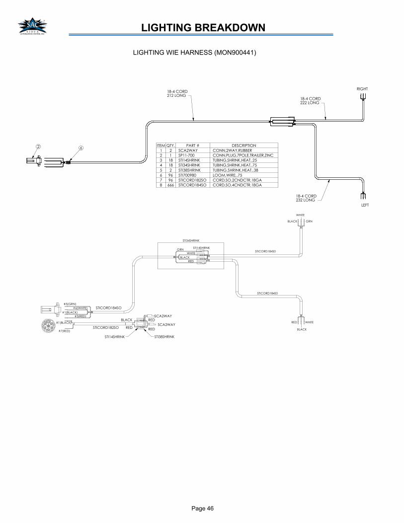
Page 46
LIGHTING BREAKDOWN
��������
���
��������
���
��������
�
��������
��������
���������
� �� � �� ��� �� ����� ��
� � ������� ������������ ��
� � �����!"" ����������!����� ������#��
� �� � ������$ � �������$���� ���%
� �� � ������$ � �������$���� ��!%
% � � ������$ � �������$���� ����
� &� � !""&�" ����������!%
! &� � �������� ����������� ������
� ��� � �������� ����������� �������
�� �
�%'���(
� ������$
��
� ������$
��
�������
���$
��
�������
� ��������
� ��������
��'��(
��' ���$(
��' ���$(
�!'��(
�
�
��
%
�
� �������"
� ������$
!
���
�� �
���$
��
���
� �������"
��
���$
�� �
���$
� ������$
��'�� �(
LIGHTING WIE HARNESS (MON900441)

Page 47
NOTES
Page 48
�
����������������
������������������� ����������������������������������������������������� �!"�#������
�������������!���"#�����$�����"�����%���������� ������������!���"#����������#�$!��������������
$��"��#�"����&'�����������������$�����#������$������ ��������($�����!����������$��������!$�����
�����"�������������������"#��!"�#�������������#����������!���"#���� �!�����$������"�����"#�"�� �
����!�������� ���� "�����������!���"#���������$& �������$�"���������##�����#����������)�������"#�����
��������������������������!�����������$����������������#��&���������������)����"� ��
�
��������������
�����&�*���������'����$������ ���������($�����!���� �&������#��*��������!�������������'��������
���+#�$$��#�� �"���������,�$����������� �#�$$��#�� �"����������������-#�!�������� ����. ����
!���"#�������#����� �&������#��*��������!�������������'��������� �"�����������������'�!��������� �&��
����#��*�����$��������������� �*��'�&'������������ ���������������� �!"�#�������
�
� ��������������
�������������������!���"#�����#�$!��������� �����#�����$���������&�*���������'��"����������������'�
!������������� ��"����������!��������� �&������������#���'�����"�����%������ �����#�����'����#����#��
�"#����� "����!��*�������������������������"��������� ������!���������*���������/0���'���������
���#�*��'����������� "����� ��������'��"&$��������$"�����# "�������������� �!�������1"��������� ����
�������!��!�� '��� ����"���������'�# ��$��������&���������������'��������� �&��$�����2�&����������
��#���'������� �������!�#��������� �&���������������������#���'���������"�����%������ ����234�����
�� �!�'�����#�$$���#����������������-!��������!���������������$������������5�����������������*�#�����
�*�� �& ������������������!�'����������������#�����#����&�������#�$$���#�����������!���������
$������&'��������5������������� �����������������$�������#���'�������������)���-!������������ �������
���'���� �"������������'���������� ��������'���#��������� �&������ 4�
�
��� �����
������������'���� ������!! '����#�$!������!���������##������������!���"#�������$��"��#�"����&'�
�����������#��#���'������������'��������$��"��#�"���������������$����������������������" ���
$��������#����� �����&��#�*�����"�����������������'��������������'���� �&��*���������'�!�������!�����
����$��"��#�"����&'���������"��������������$�����������������*�#�����������!���"#���#�*�����&'������
�������'�����������'��������*������$�������"�������#���������� ������������&"� ��$�#�����'��
�
�������������������������������������� ���������������
� ��������������������������������������������������������
����������� ��������������������������������������
��� �����������������������������������������������
����� ����� ��������������������� ������� �����������
����������������� ������������������������������������
�����������������������������������������������
�������
�
������������ ���!" ���#�$%&��!$'�#��$�(����#�%()�#*�#+��'�#,+-���.!� #+��(#�!-��#��#/0!"%�!#(�
��"%�,!("�$#,�0��'���!#+�0)��#0,��
�
�����11234���������������������� ���������**�-�!���14561�
Page 49
�
���������������
���� �������������������������
�
���������������������������������������������� ��!��"���������#��������������$���%!��&����
������������������� �����'%����#�����!�����������(�����������!�� ��!��"�����
���� �������)�*�����)�+� �,� ��-�!�������������������!����������!����������!�����
� ��������!#��������$����.�
�
)�*�����/�*�!�������!#�������!�� �����"�����0��� ����.���
����������������!����������!��������� ��!��"������������������!����������!��"��������!����������!����
�
� ����������$�����������������!&�������1������$����������!�� �����!����������!��������� ��������
�������!������� �����!����������!��������!����!���!&���� ���!����!#���$�������� �����$����
�������#!��� ���������!�����������������������������!�����!�������������#!��������� ������
#���!�$�����$����!�����#!�����!�������!#�� ������#���!�$�������!������!&������������ ���
�������$��������������$�������!�����������#����2��
�
� ����������$��!����!���!&���� ���!���!#����!���������!��������!�����!��� ��"���� �����$�
����$�!� ���� ����������#!����� ��������������!���������!#����������������!������#����&����!��
� ����� ����������$�����$��!����������!�������!��� �� ���$���������!���!����������!� ���� ���
�!����������������� �&��������������� !���� ��������������!&���!#������
�
����� ��������!��&��������������#!���!����������������"�����!�����!#����!���!����"����������������
������"�!���!#�� ��#�������!#���$�������!�����!���������!�!���������!����$��
�
,� ��-��� 3�����+��*�))�3������3� ��� �3����*���� -�
��3����)-��0�� ����0���*��4��0��������� ��,� ��-�
��5� �6���
�
�%���,� ��-��������3�3��)-�����%�������)�0� �%��� �* ����
���%� �7�3������3��� �+��� ��3��-����+�� �����6�3����%���
,� ��-������0 ���)-���)�����*��-���%� �,� ��������0 ����3�� �
�0)��3����)�3�6��-��0)��3�,� �������*�� �%���+�)��-�� �
*� ���0� ����)� �0� 0�����3��������%� ��������� ����%� �7����-�
��%� �0� ������������*� �����-���%� �)��+�)��-����%� ��� ����
,� �������,%��%�����3�+�-�3��%��3��� �0�����*��%��*����
%� ��*��
�
,�������&��� ����" ���!���8������!&��������!���$�!#�!�����!��������� !����!�����!��
!���"���!����"�����"��!��������&�!���$��!����
�
�
����������������������� �##����&��9:;<9�

Page 50
NOTES

Page 51
NOTES

Page 52
SIOUX AUTOMATION CENTER INC.877 1ST AVE. NW SIOUX CENTER, IA 51250
PH: (712) 722-1488FAX: (712) 722-1487
TOLL FREE: 1-866-722-1488
http://www.siouxautomation.com