quality, service - apollo safety and relief valves made in...
TRANSCRIPT


A history ofQuality, Service and Innovation
Now in its ninth decade, Conbraco Industries, Inc. is a leading manufacturer of flow control products for U.S. and international markets. The company’s headquarters is based in Matthews, North Carolina with manufacturing plants and foundries located in Pageland and Conway, South Carolina.
Conbraco has a history of new product development and innovation that dates back to the company’s inception in 1928. Today, the Conbraco line of products is marketed under the “Apollo Valves” brand and includes: ball valves, butterfly valves, backflow prevention devices, water pressure reducing valves, mixing valves, safety relief valves, water gauges, strainers, actuation and ApolloXpress products.
Conbraco’s vertically integrated manufacturing ensures a consistency of production, testing, quality and availability. You can be assured that Conbraco flow control products will deliver long term reliability. All Conbraco plants are registered to ISO 9001:2008 quality standards.
The Conbraco line continues to expand with new products, designs and advanced materials to better serve the needs of our customers. Markets served include: chemical processing, pulp and paper, petroleum, residential and commercial plumbing and heating, OEM, irrigation, water works, and fire protection.
table of contentsY-Strainers ......................................................................................................................................................................................................................................... 3
ENGINEERING DATA
Screen Openings for Y-Strainers ........................................................................................................................................................................................ 4
Y-Strainer Pressure Drop – Liquids .................................................................................................................................................................................... 5
Screen Correction Factor Chart .......................................................................................................................................................................................... 6
Y-Strainer Pressure Drop – Saturated Steam ................................................................................................................................................................. 7
Y-Strainer Effective Screen Area ........................................................................................................................................................................................10
Check List and Suggested Specifications .............................................................................................................................................................................. 8
Installation and Maintenance Instructions ........................................................................................................................................................................... 9
Apollo Flanged Y-Strainer Order Schematic ........................................................................................................................................................................10
Warranty Info ..................................................................................................................................................................................................................................11
flanged series Y-strainers
Customer Service (704) 841-6000For additional information, submittal sheets and manuals, visit www.apollovalves.com
3
Y-strainersapollo® SerIeS 125yf Iron pIpe flanged y-StraInerS
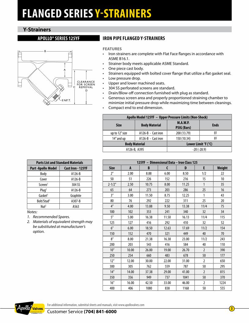
features• Iron strainers are complete with Flat Face flanges in accordance with ASME B16.1.• Strainer body meets applicable ASME Standard.• One piece cast body.• Strainers equipped with bolted cover flange that utilize a flat gasket seal.• Low pressure drop.• Upper and lower machined seats.• 304 SS perforated screens are standard.• Drain/Blow-off connection furnished with plug as standard.• Generous screen area and properly proportioned straining chamber to minimize initial pressure drop while maximizing time between cleanings.• Compact end to end dimension.
apollo Model 125yf – Upper pressure limits (non-Shock)
Size Body Material M.a.W.p.pSIg (Bars) ends
up to 12” size A126-B - Cast iron 200 (13.79) FF14” and up A126-B - Cast iron 150 (10.34) FF
Body Material lower limit °f (°C)A126-B, A395 -20 (-28.9)
parts list and Standard Materialspart -apollo Model Cast Iron - 125yf
Body A126-BCover A126-B
Screen1 304 SSPlug2 A126-B
Gasket1 GraphiteBolt/Stud2 A307-B
Nut2 A563Notes:1. Recommended Spares.2. Materials of equivalent strength may be substituted at manufacturer’s option.
125yf – dimensional data – Iron Class 125Size a B C d e Weight
2” 2.00 8.88 6.00 8.50 1/2 2250 51 226 152 216 15 10
2-1/2” 2.50 10.75 8.00 11.25 1 3565 64 273 203 286 25 163” 3.00 11.50 8.75 12.25 1 4380 76 292 222 311 25 204” 4.00 13.88 9.50 13.38 11/4 75
100 102 353 241 340 32 345” 5.00 16.38 11.50 16.13 11/4 115
125 127 416 292 410 32 526” 6.00 18.50 12.63 17.69 11/2 154
150 152 470 321 449 40 708” 8.00 21.38 16.38 23.00 11/2 243
200 203 543 416 584 40 11010” 10.00 26.00 19.00 26.70 2 390250 254 660 483 678 50 17712” 12.00 30.00 22.00 31.00 2 650300 305 762 559 787 50 29514” 14.00 37.38 29.00 41.00 2 815350 356 949 737 1041 50 37016” 16.00 42.50 33.00 46.00 2 1224400 406 1080 838 1168 50 555

flanged series Y-strainers
Customer Service (704) 841-60004
www.apollovalves.com
engineering Data screen openings for Y-strainersfaCtorS to ConSIder
purposeIf the basket strainer is being used for protection rather than direct filtration, Apollo’s standard screens will suffice in most applications.
serviceWith services that require extremely sturdy screens, such as high pressure/ temperature applications or services with high viscosities, Apollo® recommends that perforated screens without mesh liners be used. If mesh is required to obtain a certain level of filtration, then Apollo recommends a trapped perf./mesh/perf. combination.
filtration levelWhen choosing a perf. or a mesh/perf. combination attention should be given to ensure overstraining does not occur. As a general rule the specified level of filtration should be no smaller than half the size of the particle to be removed. If too fine a filtration is specified the pressure drop through the strainer will increase very rapidly, possibly causing damage to the basket.
Notes:1. Screen openings other than those shown above are available.2. Custom manufactured screens are available upon request. Please consult factory. 3. All mesh screens include liner; .045 Perf 3” and smaller .125 Perf 4” and larger.
1/4”
Dia.
- 40
% O.
A.
3/16
” Dia.
- 50
% O.
A.
5/32
” Dia.
- 58
% O.
A
1/8”
Dia.
- 40
% O.
A.
3/32
” Dia.
- 39
% O.
A
1/16
” Dia.
- 37
% O.
A.
3/64
” Dia.
- 36
% O.
A.
1/32
” Dia.
- 40
% O.
A.
0.027
” Dia.
- 23
%
O.A.
20 M
esh -
49%
O.A.
0.035
” Ope
nings
30 M
esh -
45%
O.A.
0.022
” Ope
nings
40 M
esh -
41%
O.A.
0.016
” Ope
nings
60 M
esh -
38%
O.A.
0.010
” Ope
nings
80 M
esh -
36%
O.A.
0.008
” Ope
nings
100 M
esh -
30%
O.A.
0.006
” Ope
nings
SCreen typeS/dIMenSIonS
Standard ScreensSize range opening
2” - 3” 0.045 in.50mm - 80mm 1.2mm
4” and larger 0.125 in.100mm and larger 3.2mm

flanged series Y-strainers
Customer Service (704) 841-6000For additional information, submittal sheets and manuals, visit www.apollovalves.com
5
engineering Data Y-strainer pressure Drop – liquids
Notes: 1. Pressure drop curves are based on water flow with standard screens.2. See next page for correction factors to be used with other fluids and/or screen openings.
y-StraIner preSSUre drop - (SIzeS 2” - 16”)
The following optional features are available for most Apollo Y-Strainers. Please consult factory if required feature not shown.
Feature Description of Availability Screen openings Range 5 micron to 1/2” perf. Screen materials Carbon steel, stainless steel (304/316 and L grades), alloy 20, monel 400, hastalloy C, Titanium, etc. Screen construction Perforated plate, mesh and wedge wire. Gaskets Any material commercially available. Special body materials Consult factory. Special coatings FDA Epoxy Coating Silicon free contamination Specially cleaned and packed - performed on request. Canadian Registration (CRN) Available on most models in province of installation.
Note: 1. Strainer size may effect the ability to apply certain coatings and linings.
figure 1
featUreS & avaIlaBIlIty
flanged series Y-strainers
Customer Service (704) 841-60006
www.apollovalves.com
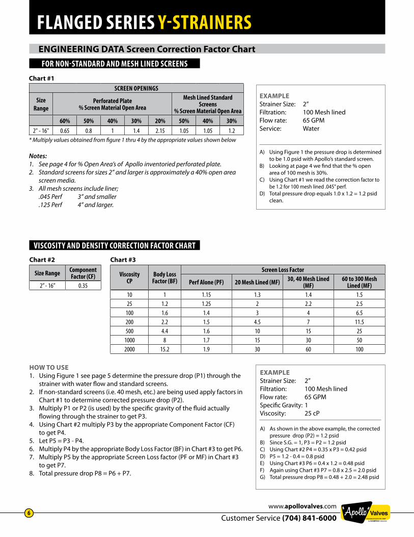
engineering Data screen correction factor chartfor non-Standard and MeSh lIned SCreenS
chart #1SCreen openIngS
Size range
perforated plate % Screen Material open area
Mesh lined Standard Screens
% Screen Material open area60% 50% 40% 30% 20% 50% 40% 30%
2" - 16" 0.65 0.8 1 1.4 2.15 1.05 1.05 1.2* Multiply values obtained from figure 1 thru 4 by the appropriate values shown below
Notes: 1. See page 4 for % Open Area’s of Apollo inventoried perforated plate.2. Standard screens for sizes 2” and larger is approximately a 40% open area screen media.3. All mesh screens include liner; .045 Perf 3” and smaller .125 Perf 4” and larger.
chart #3
viscosityCp
Body lossfactor (Bf)
Screen loss factor
perf alone (pf) 20 Mesh lined (Mf) 30, 40 Mesh lined (Mf)
60 to 300 Mesh lined (Mf)
10 1 1.15 1.3 1.4 1.525 1.2 1.25 2 2.2 2.5
100 1.6 1.4 3 4 6.5200 2.2 1.5 4.5 7 11.5500 4.4 1.6 10 15 25
1000 8 1.7 15 30 502000 15.2 1.9 30 60 100
chart #2
Size range Component factor (Cf)
2” - 16” 0.35
vISCoSIty and denSIty CorreCtIon faCtor Chart
How to use1. Using Figure 1 see page 5 determine the pressure drop (P1) through the strainer with water flow and standard screens.2. If non-standard screens (i.e. 40 mesh, etc.) are being used apply factors in Chart #1 to determine corrected pressure drop (P2).3. Multiply P1 or P2 (is used) by the specific gravity of the fluid actually flowing through the strainer to get P3.4. Using Chart #2 multiply P3 by the appropriate Component Factor (CF) to get P4.5. Let P5 = P3 - P4.6. Multiply P4 by the appropriate Body Loss Factor (BF) in Chart #3 to get P6.7. Multiply P5 by the appropriate Screen Loss factor (PF or MF) in Chart #3 to get P7.8. Total pressure drop P8 = P6 + P7.
exampleStrainer Size: 2”Filtration: 100 Mesh lined Flow rate: 65 GPMService: Water
A) Using Figure 1 the pressure drop is determined to be 1.0 psid with Apollo’s standard screen.B) Looking at page 4 we find that the % open area of 100 mesh is 30%.C) Using Chart #1 we read the correction factor to be 1.2 for 100 mesh lined .045” perf.D) Total pressure drop equals 1.0 x 1.2 = 1.2 psid clean.
exampleStrainer Size: 2”Filtration: 100 Mesh lined Flow rate: 65 GPMSpecific Gravity: 1Viscosity: 25 cP
A) As shown in the above example, the corrected pressure drop (P2) = 1.2 psidB) Since S.G. = 1, P3 = P2 = 1.2 psidC) Using Chart #2 P4 = 0.35 x P3 = 0.42 psidD) P5 = 1.2 - 0.4 = 0.8 psidE) Using Chart #3 P6 = 0.4 x 1.2 = 0.48 psidF) Again using Chart #3 P7 = 0.8 x 2.5 = 2.0 psidG) Total pressure drop P8 = 0.48 + 2.0 = 2.48 psid

flanged series Y-strainers
Customer Service (704) 841-6000For additional information, submittal sheets and manuals, visit www.apollovalves.com
7
engineering Data Y-strainer pressure Drop – saturated steam
wHereQs = Equivalent Steam Flow, lbs./hr.Qg = Air or gas flow, SCFM.t = Temperature, °F.s.g. = Specific gravity (s.g. = 1 for air.)DP = Pressure Drop, psidP2 = Outlet Pressure
• Locate steam flow.• Follow horizontal line to required pressure.• Follow vertical line downwards to required strainer size.• Follow horizontal line to read pressure drop.• Pressure drop equals 2.0 psid.
Qs = 0.138 Qg
SIzeS 2” - 16”
exampleService: Saturated Steam FlowPressure: 400 psigSteam Flow: 90,000 Lbs/hrSize: 8”
A) Locate steam flow.B) Follow horizontal line to required pressure.C) Follow vertical line downwards to required strainer size.D) Follow horizontal line to read pressure dropE) Pressure drop equals 2.0 psid.
Notes: 1. Pressure drop curve is based on saturated steam flow with standard screens. See page 5 for correction factors to be used with other screen openings.2. Chart can be used for air and gas by using the following formula:
flanged series Y-strainers
Customer Service (704) 841-60008
www.apollovalves.com
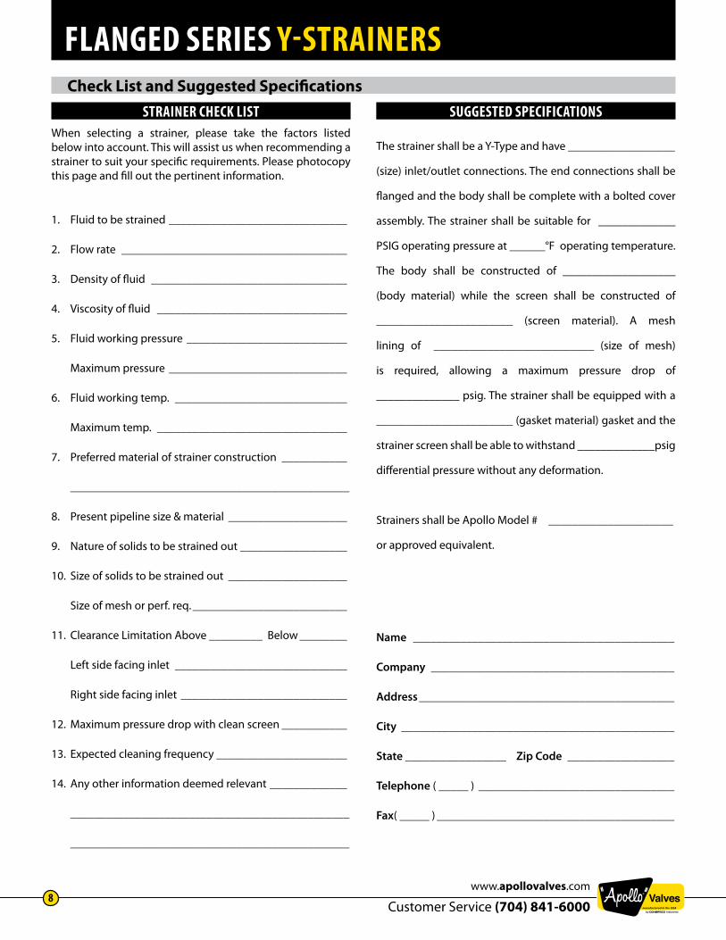
check list and suggested specificationsStraIner CheCk lISt
When selecting a strainer, please take the factors listed below into account. This will assist us when recommending a strainer to suit your specific requirements. Please photocopy this page and fill out the pertinent information.
1. Fluid to be strained ______________________________
2. Flow rate ______________________________________
3. Density of fluid _________________________________
4. Viscosity of fluid ________________________________
5. Fluid working pressure ___________________________
Maximum pressure ______________________________
6. Fluid working temp. _____________________________
Maximum temp. ________________________________
7. Preferred material of strainer construction ___________
_______________________________________________
8. Present pipeline size & material ____________________
9. Nature of solids to be strained out __________________
10. Size of solids to be strained out ____________________
Size of mesh or perf. req. __________________________
11. Clearance Limitation Above _________ Below ________
Left side facing inlet _____________________________
Right side facing inlet ____________________________
12. Maximum pressure drop with clean screen ___________
13. Expected cleaning frequency ______________________
14. Any other information deemed relevant _____________
_______________________________________________
_______________________________________________
SUggeSted SpeCIfICatIonS
The strainer shall be a Y-Type and have __________________
(size) inlet/outlet connections. The end connections shall be
flanged and the body shall be complete with a bolted cover
assembly. The strainer shall be suitable for _____________
PSIG operating pressure at ______°F operating temperature.
The body shall be constructed of ___________________
(body material) while the screen shall be constructed of
_______________________ (screen material). A mesh
lining of ___________________________ (size of mesh)
is required, allowing a maximum pressure drop of
______________ psig. The strainer shall be equipped with a
_______________________ (gasket material) gasket and the
strainer screen shall be able to withstand _____________psig
differential pressure without any deformation.
Strainers shall be Apollo Model # _____________________
or approved equivalent.
Name ____________________________________________
Company _________________________________________
Address ___________________________________________
City ______________________________________________
State _________________ Zip Code __________________
Telephone ( _____ ) _________________________________
Fax( _____ ) ________________________________________

flanged series Y-strainers
Customer Service (704) 841-6000For additional information, submittal sheets and manuals, visit www.apollovalves.com
9
installation and maintenance instructions
A. Ensure all machined surfaces are free of defects and that the inside of the strainer is free of foreign objects.B. For horizontal pipelines, the strainer should be installed so that the drain connection is pointed downwards.C. For flanged end strainers, the flange bolting should be tightened gradually in a back and forth clockwise motion. D. Once installed, increase line pressure gradually and check for leakage around joints.E. If the strainer is supplied with a start-up screen, monitor pressure drop carefully.
NOTE: Flat face mating flanges and full face gaskets must be used with 125YF series strainers to avoid damage to the cast iron body.
IMPORTANTUltimate responsibility for strainer and material selection rests with the customer, as only the customer knows the particular use to which the strainer will be put and the exact operating parameters to which it will be subjected.
A. Drain piping.B. Vent line to relieve pressure.C. Secure necessary lifting equipment to strainer assembly.D. Loosen flange bolts (Pipe flanges only).E. Remove inlet/outlet flange bolts and carefully remove strainer.
CAUTION SHOULD BE TAKEN DUE TO POSSIBLE EMISSION OF PROCESS MATERIAL FROM PIPING. ALWAYS ENSURE NO LINE PRESSURE EXISTS WHEN OPENING COVER.
For maximum efficiency, determine the length of time it takes for the pressure drop to double that in the clean condition. Once the pressure drop reaches an unacceptable value, shut down line and follow the “Screen Replacement Instructions”. A pressure gauge installed before and after the strainer in-line will indicate pressure loss due to clogging and may be used to determine when cleaning is required.
It is recommend that the system and strainer be depressurized before attempting any repair work. After removing all pressure, the system should be drained, any connections to the blow-off plug should be removed, and the following procedure should be used to replace the screen.
A. Attach cable or chain to strainer cover (1) and apply sufficient tension to prevent cover from dropping.B. Remove bolts from cover.C. Remove cover, clean and inspect gasket surface of cover.D. Remove and discard old gasket.E. Remove and clean or discard old screen.F. Clean and inspect gasket surface of body. If gasket surface of cover or body is damaged, the damaged component must be replaced.G. Push clean screen into position in body.H. Position new gasket in place on body.I. Line up screen and put cover in place on body.J. Be sure gasket, bolt holes, and screen are properly aligned.K. Put in bolts and nuts as requiredL. Tighten bolts, using “star” pattern to prevent damaging parts. Alternate tightening 180° apart. Tighten bolts sufficiently to stop leakage under test and service conditions.
StraIner InStallatIon InStrUCtIonS
StraIner reMoval InStrUCtIonS
MaIntenanCe InStrUCtIonS
SCreen replaCeMent

flanged series Y-strainers
Customer Service (704) 841-600010
www.apollovalves.com
engineering Data Y-strainer effective screen area
SerIeS 125yf
pipeSize (In.)
Std.opening (In.)
nominal area of pipe fitting
(Sq. In.)
gross Screenarea
(Sq. In.)free area(Sq. In.)
ratio freearea to
pipe area2 0.045 3.14 30.07 10.82 3.45
2-1/2 0.045 4.91 44.33 15.96 3.253 0.045 7.07 56.45 20.32 2.884 0.125 12.57 98.91 39.56 3.155 0.125 19.63 147.11 58.85 3.006 0.125 28.27 179.19 71.68 2.548 0.125 50.27 334.38 133.75 2.66
10 0.125 78.54 505.21 202.08 2.5712 0.125 113.10 665.77 266.31 2.3514 0.125 137.89 1186.34 474.54 3.4416 0.125 182.65 1446.85 578.74 3.17
apollo flanged Y-strainer order schematic
NOTEs: *All mesh screens are reinforced with a perforated liner.2” - 3”: .045 Perf4” - Larger: .125 Perf
Model125Y (Flat Face)
SCreen type20 Mesh = M2040 Mesh = M4060 Mesh = M6080 Mesh = M80100 Mesh = M100.045 Perf = P045.062 Perf = P062.125 Perf = P125.250 Perf = P250
valve type/ConneCtIon SIzeFlanged 2” = F02Flanged 2.5” = F25Flanged 3” = F03Flanged 4” = F04Flanged 5” = F05Flanged 6” = F06Flanged 8” = F08Flanged 10” = F10Flanged 12” = F12Flanged 14” = F14Flanged 16” = F16
CoatIngBlank Standard No CoatingE Epoxy Coating, FDA Approved
125Y - xxx - xxx x - x

flanged series Y-strainers
Customer Service (704) 841-6000For additional information, submittal sheets and manuals, visit www.apollovalves.com
11
Conbraco Industries, Inc. warranties, to its initial purchaser only, that its products which are delivered to the initial purchaser will be of the kind described in the order or pricelist and will be free of defects in workmanship or material for a period of TWO years from the date of delivery to you, our initial purchaser.
Should any failure to conform to this warranty appear within two years after the date of the initial delivery to our initial purchaser, Conbraco will, upon written notification thereof and substantiation that the goods have been stored, installed, maintained and operated in accordance with Conbraco’s recommendations and standard industry practice, correct such defects by suitable repair or replacement at Conbraco’s own expense.
THIS WARRANTY IS EXCLUSIVE AND IS IN LIEU OF ANY IMPLIED WARRANTY OF MERCHANTABILITY, FITNESS FOR A PARTICULAR PURPOSE OR OTHER WARRANTY OF QUALITY WHETHER EXPRESSED OR IMPLIED, EXCEPT THE WARRANTY OF TITLE AND AGAINST PATENT INFRINGEMENT. Correction of non-conformities, in the manner and for the period of time provided above, shall constitute fulfillment of all liabilities of Conbraco to our initial purchaser, with respect to the goods, whether based on contract, negligence, strict tort or otherwise. It is the intention of Conbraco Industries, Inc. that no warranty of any kind, whether express or implied, shall pass through our initial purchaser to any other person or corporation.
LIMITATION OF LIABILITY: Conbraco Industries, Inc. SHALL NOT UNDER ANY CIRCUMSTANCES BE LIABLE FOR SPECIAL OR CONSEQUENTIAL DAMAGES SUCH AS, BUT NOT LIMITED TO, DAMAGES OR LOSS OF OTHER PROPERTY OR EQUIPMENT, LOSS OF PROFITS OR REVENUE, COST OF CAPITAL, COST OF PURCHASED OR INITIAL PURCHASER , AND ALL OTHERS, SET FORTH HEREIN ARE EXCLUSIVE, AND THE LIABILITY OF CONBRACO WITH RESPECT TO SAME SHALL NOT, AS EXPRESSLY PROVIDED HEREIN, EXCEED THE PRICE OF THE GOODS UPON WHICH SUCH LIABILITY IS BASED.
warrantY anD limitations of liabilitYIn
tern
atIo
nal
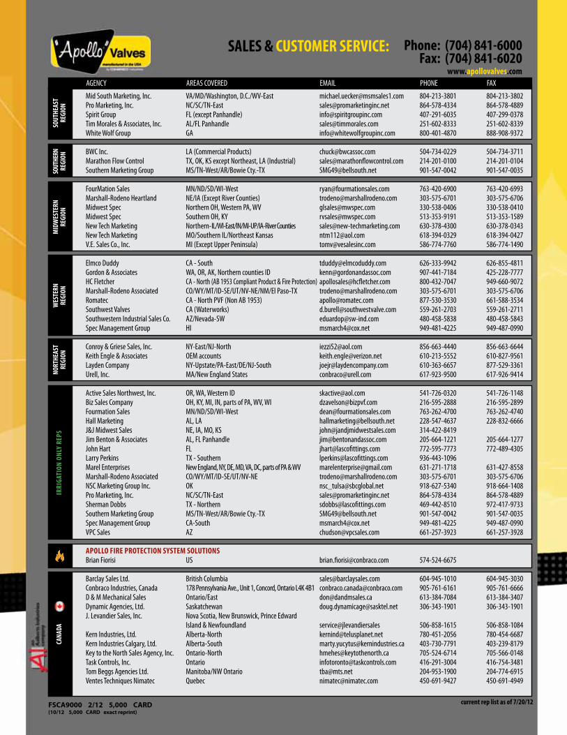
Conbraco International Sales: Jose Arias Mexico [email protected] 1-956-631-4542 1-956-631-4681Luis Guzman Puerto Rico/Caribbean [email protected] 1-787-739-5620 JR Jefferson Central & South America [email protected] 1-832-220-3783 Mike Link United Kingdom [email protected] 44-07957-843906Luke Liu China [email protected] 86-411-869-02498 Jonathan Yap Asia [email protected] 65-9626-9241 65-6753-0131Brencliff Group Australia [email protected] 61-0477-223110Pegler Yorkshire Mid East Middle East/India [email protected] 971-4-454-2353 971-4-454-2352 Europe/Africa/Israel Contact Customer Service 1-704-841-6000 1-704-841-6021
AREAS COVERED EMAIL PHONE FAX
international sales reps & regional managers
apollo valveS regIonal SaleS dIreCtorS P.O. BOX 247, Matthews, NC 28106Brian Blalock East [email protected] 704-614-3744 704-841-6021Skip Wilson West [email protected] 760-330-3293 775-854-5722apollo valveS regIonal ManagerSKevin Ashworth Mid Atlantic [email protected] 757-272-6200Steve Brown Northwest [email protected] 425-985-5095 253-862-3548Andy Fretz Canada - Commercial [email protected] 647-281-3161 905-761-6666Ben Lauletta Northeast [email protected] 518-795-4629 Sanford Pauly North Central [email protected] 513-716-7772 513-321-7717James Saldivar South Central - Industrial [email protected] 832-776-5547Nick Shelley South Central - Commercial [email protected] 214-790-4157Jim Todman Canada - Industrial [email protected] 905-407-8385 905-761-6666
David Beyer Northeast [email protected] 561-718-9379Ron Modugno West [email protected] 661-910-5058 661-775-0713Jimmy White Central [email protected] 731-234-2372 731-779-3608Ben Freeman Southeast [email protected] 205-919-4944Rick Williamson Eastern Specifications Manager [email protected] 386-451-2307
regI
onal
Man
ager
S
laSCo fIttIngS IrrIgatIon regIonal ManagerS P.O. BOX 116, Brownsville, TN 38012
current as of 10/1/12
fsca9000 2/12 5,000 carD (10/12 5,000 carD exact reprint)
phone: (704) 841-6000fax: (704) 841-6020
www.apollovalves.com
SaleS & CUStoMer ServICe:
current rep list as of 7/20/12
MId
WeS
tern
re
gIon
SoUt
heaS
t re
gIon
SoUt
hern
re
gIon
WeS
tern
re
gIon
nort
heaS
t re
gIon
IrrI
gatI
on o
nly
repS
Cana
da
Mid South Marketing, Inc. VA/MD/Washington, D.C./WV-East [email protected] 804-213-3801 804-213-3802Pro Marketing, Inc. NC/SC/TN-East [email protected] 864-578-4334 864-578-4889Spirit Group FL (except Panhandle) [email protected] 407-291-6035 407-299-0378Tim Morales & Associates, Inc. AL/FL Panhandle [email protected] 251-602-8333 251-602-8339White Wolf Group GA [email protected] 800-401-4870 888-908-9372
BWC Inc. LA (Commercial Products) [email protected] 504-734-0229 504-734-3711Marathon Flow Control TX, OK, KS except Northeast, LA (Industrial) [email protected] 214-201-0100 214-201-0104Southern Marketing Group MS/TN-West/AR/Bowie Cty.-TX [email protected] 901-547-0042 901-547-0035
FourMation Sales MN/ND/SD/WI-West [email protected] 763-420-6900 763-420-6993Marshall-Rodeno Heartland NE/IA (Except River Counties) [email protected] 303-575-6701 303-575-6706Midwest Spec Northern OH, Western PA, WV [email protected] 330-538-0406 330-538-0410Midwest Spec Southern OH, KY [email protected] 513-353-9191 513-353-1589New Tech Marketing Northern-IL/WI-East/IN/MI-UP/IA-River Counties [email protected] 630-378-4300 630-378-0343New Tech Marketing MO/Southern IL/Northeast Kansas [email protected] 618-394-0329 618-394-0427V.E. Sales Co., Inc. MI (Except Upper Peninsula) [email protected] 586-774-7760 586-774-1490
Elmco Duddy CA - South [email protected] 626-333-9942 626-855-4811Gordon & Associates WA, OR, AK, Northern counties ID [email protected] 907-441-7184 425-228-7777HC Fletcher CA - North (AB 1953 Compliant Product & Fire Protection) [email protected] 800-432-7047 949-660-9072Marshall-Rodeno Associated CO/WY/MT/ID-SE/UT/NV-NE/NM/El Paso-TX [email protected] 303-575-6701 303-575-6706Romatec CA - North PVF (Non AB 1953) [email protected] 877-530-3530 661-588-3534Southwest Valves CA (Waterworks) [email protected] 559-261-2703 559-261-2711Southwestern Industrial Sales Co. AZ/Nevada-SW [email protected] 480-458-5838 480-458-5843Spec Management Group HI [email protected] 949-481-4225 949-487-0990
Conroy & Griese Sales, Inc. NY-East/NJ-North [email protected] 856-663-4440 856-663-6644Keith Engle & Associates OEM accounts [email protected] 610-213-5552 610-827-9561Layden Company NY-Upstate/PA-East/DE/NJ-South [email protected] 610-363-6657 877-529-3361Urell, Inc. MA/New England States [email protected] 617-923-9500 617-926-9414
Active Sales Northwest, Inc. OR, WA, Western ID [email protected] 541-726-0320 541-726-1148 Biz Sales Company OH, KY, MI, IN, parts of PA, WV, WI [email protected] 216-595-2888 216-595-2899Fourmation Sales MN/ND/SD/WI-West [email protected] 763-262-4700 763-262-4740Hall Marketing AL, LA [email protected] 228-547-4637 228-832-6666J&J Midwest Sales NE, IA, MO, KS [email protected] 314-422-8419 Jim Benton & Associates AL, FL Panhandle [email protected] 205-664-1221 205-664-1277John Hart FL [email protected] 772-595-7773 772-489-4305Larry Perkins TX - Southern [email protected] 936-443-1096 Marel Enterprises New England, NY, DE, MD, VA, DC, parts of PA & WV [email protected] 631-271-1718 631-427-8558Marshall-Rodeno Associated CO/WY/MT/ID-SE/UT/NV-NE [email protected] 303-575-6701 303-575-6706NSC Marketing Group Inc. OK [email protected] 918-627-5340 918-664-1408Pro Marketing, Inc. NC/SC/TN-East [email protected] 864-578-4334 864-578-4889Sherman Dobbs TX - Northern [email protected] 469-442-8510 972-417-9733Southern Marketing Group MS/TN-West/AR/Bowie Cty.-TX [email protected] 901-547-0042 901-547-0035Spec Management Group CA-South [email protected] 949-481-4225 949-487-0990VPC Sales AZ [email protected] 661-257-3923 661-257-3928
apollo fIre proteCtIon SySteM SolUtIonSBrian Fiorisi US [email protected] 574-524-6675
Barclay Sales Ltd. British Columbia [email protected] 604-945-1010 604-945-3030Conbraco Industries, Canada 178 Pennsylvania Ave., Unit 1, Concord, Ontario L4K 4B1 [email protected] 905-761-6161 905-761-6666D & M Mechanical Sales Ontario/East [email protected] 613-384-7084 613-384-3407Dynamic Agencies, Ltd. Saskatchewan [email protected] 306-343-1901 306-343-1901J. Levandier Sales, Inc. Nova Scotia, New Brunswick, Prince Edward Island & Newfoundland service@jlevandiersales 506-858-1615 506-858-1084 Kern Industries, Ltd. Alberta-North [email protected] 780-451-2056 780-454-6687Kern Industries Calgary, Ltd. Alberta-South [email protected] 403-730-7791 403-239-8179Key to the North Sales Agency, Inc. Ontario-North [email protected] 705-524-6714 705-566-0148Task Controls, Inc. Ontario [email protected] 416-291-3004 416-754-3481Tom Beggs Agencies Ltd. Manitoba/NW Ontario [email protected] 204-953-1900 204-774-6915Ventes Techniques Nimatec Quebec [email protected] 450-691-9427 450-691-4949
AGENCY AREAS COVERED EMAIL PHONE FAX