quality through manufacture...
TRANSCRIPT

Quality Through Manufacture
Gavin Bell
Hexagon Metrology UK

“We must continually challenge ourselves to consider how best to direct
the future of our industry. It is our ability to recognize and adapt our
products to the evolving needs of our customers while at the same time
leveraging emerging technologies that will determine our success going
forward.”
One of the key elements of the EMS philosophy is to create a frictionless
flow of metrology information between different elements of a
manufacturing process. The goal of this effort is major efficiency gains
in the processes involved with metrology. With these will come reduction
in lead times and cost, whilst improving quality.
In pursuit of this, we continue to examine every aspect of the tasks of
metrology and how they are performed, considering how each task can
be improved.
The Mission

Where can Metrology play it’s place throughout the manufacturing process?
What has Industry asked us for?
“A common metrology software platform that can influence from the design stage, fully integrating with the
major CAD systems and driving a full suite of data collection devices through manufacture and assembly of
components into quality products”
An “Enterprise Metrology Solution”
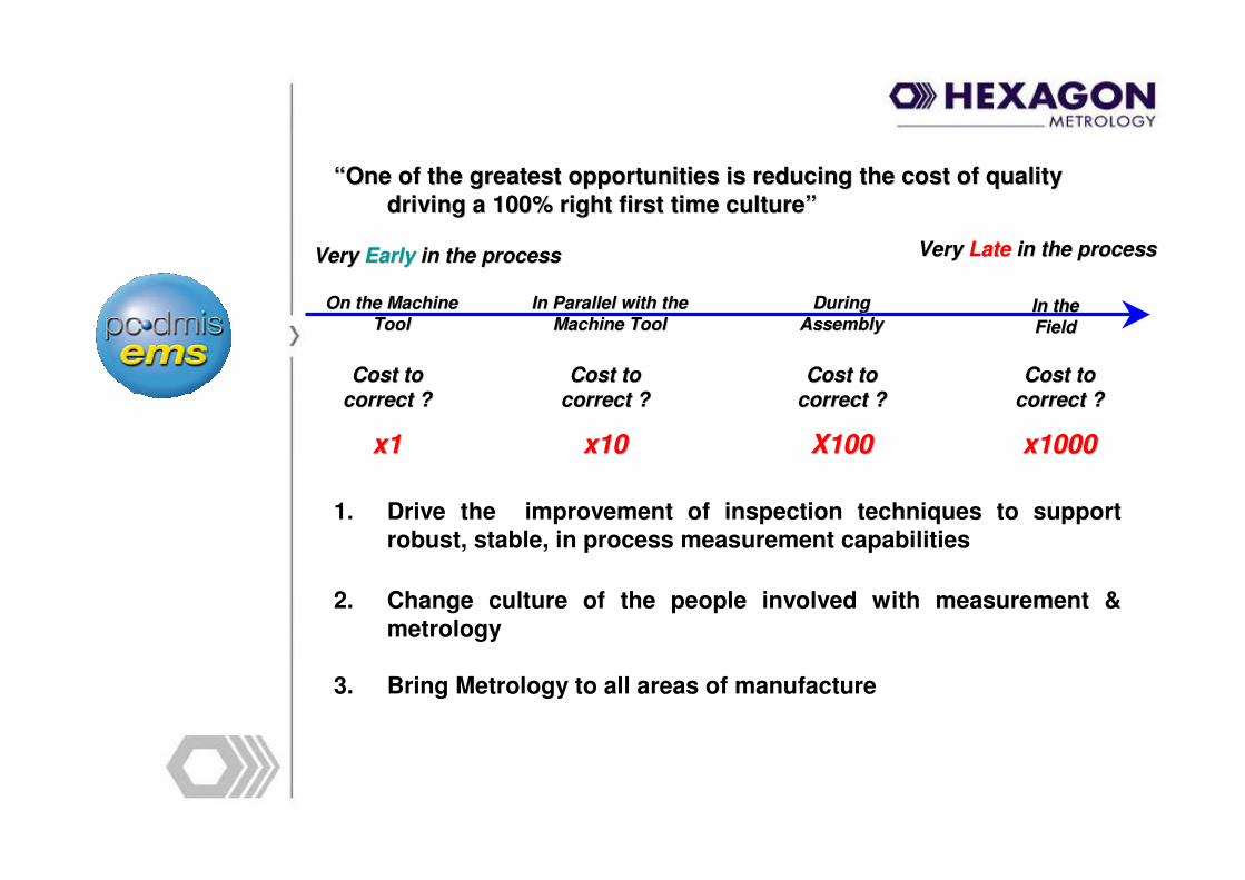
1. Drive the improvement of inspection techniques to support robust, stable, in process measurement capabilities
2. Change culture of the people involved with measurement &
metrology
3. Bring Metrology to all areas of manufacture
Very Very Early Early in the processin the process Very Very Late Late in the processin the process
Cost to Cost to
correct ?correct ?
x1x1
Cost to Cost to
correct ?correct ?
x10x10
Cost to Cost to
correct ?correct ?
X100X100
Cost to Cost to
correct ?correct ?
x1000x1000
On the Machine On the Machine
ToolToolIn Parallel with the In Parallel with the
Machine ToolMachine ToolDuring During
AssemblyAssemblyIn the In the
FieldField
“One of the greatest opportunities is reducing the cost of quali“One of the greatest opportunities is reducing the cost of quality ty
driving a 100% right first time culture” driving a 100% right first time culture”
One of the Core drivers is to have a paperless, seamless route from
design through to manufacture with feedback to design.
It is fundamental that the design intent is guaranteed throughout the
manufacturing process without compromise to it’s integrity.
For more than a decade now OEM’s have been discouraging the
translation of Cad Data from it’s native format to prevent errors in their
supply chains.
Today it is still too common to see a host of 2-D paper prints, overly
busy with feature and geometrical tolerancing. The highly complex
nature of today’s components require multiple datums and stacked
tolerancing, using max / min metal conditions to ensure the parts fit
when they come together.
All this in a World where we are facing ever compressing timelines to get
product from design screens to the customer.
The Journey Begins “Upstairs”

The First Step- Inspection Planner™
•By embedding PC-DMIS tools into the CAD suite, the designer can state
his design intent directly on the model.
•This largely negates the requirement for 2-D Paper prints and guarantees
the integrity of design, removing the need for an engineer or a number of
engineer’s to “interpret” the designer’s intent
•When the native Cad model is loaded from PC-DMIS, the “inspection
plan” is brought in with it. What does this mean?
• all dimensional and geometrical features applied at design are already present and all of the calculations made
• each feature is dimensioned from the relevant datum and applied
• regardless of the collection device or devices, this information remains true throughout the process
• it does not dictate the collection device, nor create a program for it, the programmer is free to select the appropriate device, sensor and create a program from the embedded codes
• what will be guaranteed is that the calculation of the output results will be the same for every and any programmer
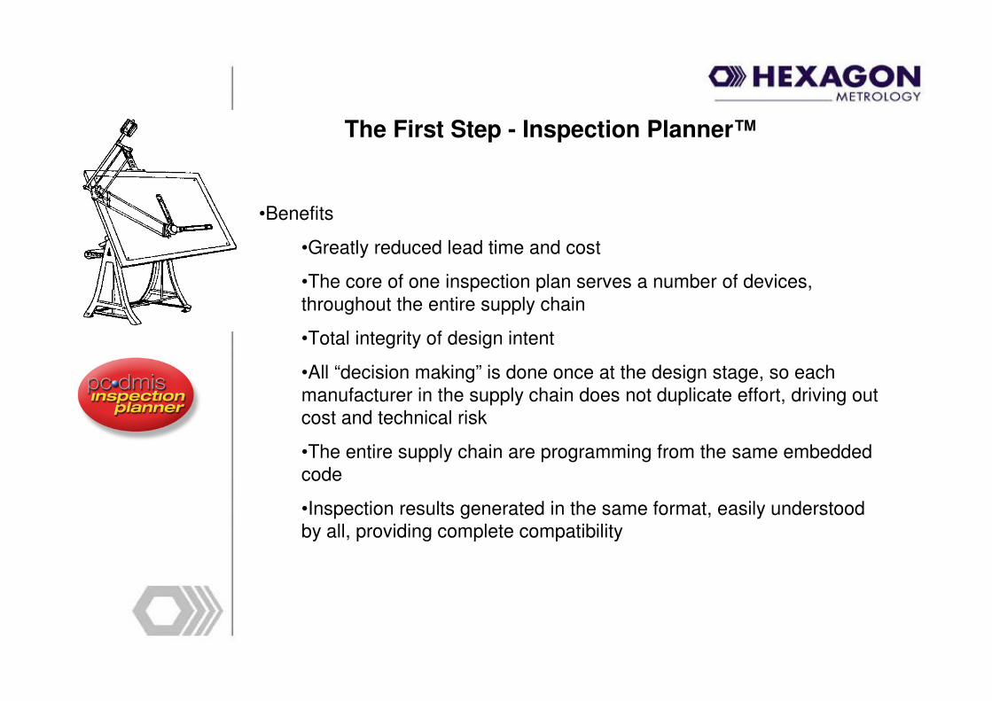
The First Step - Inspection Planner™
•Benefits
•Greatly reduced lead time and cost
•The core of one inspection plan serves a number of devices,
throughout the entire supply chain
•Total integrity of design intent
•All “decision making” is done once at the design stage, so each
manufacturer in the supply chain does not duplicate effort, driving out
cost and technical risk
•The entire supply chain are programming from the same embedded
code
•Inspection results generated in the same format, easily understood
by all, providing complete compatibility
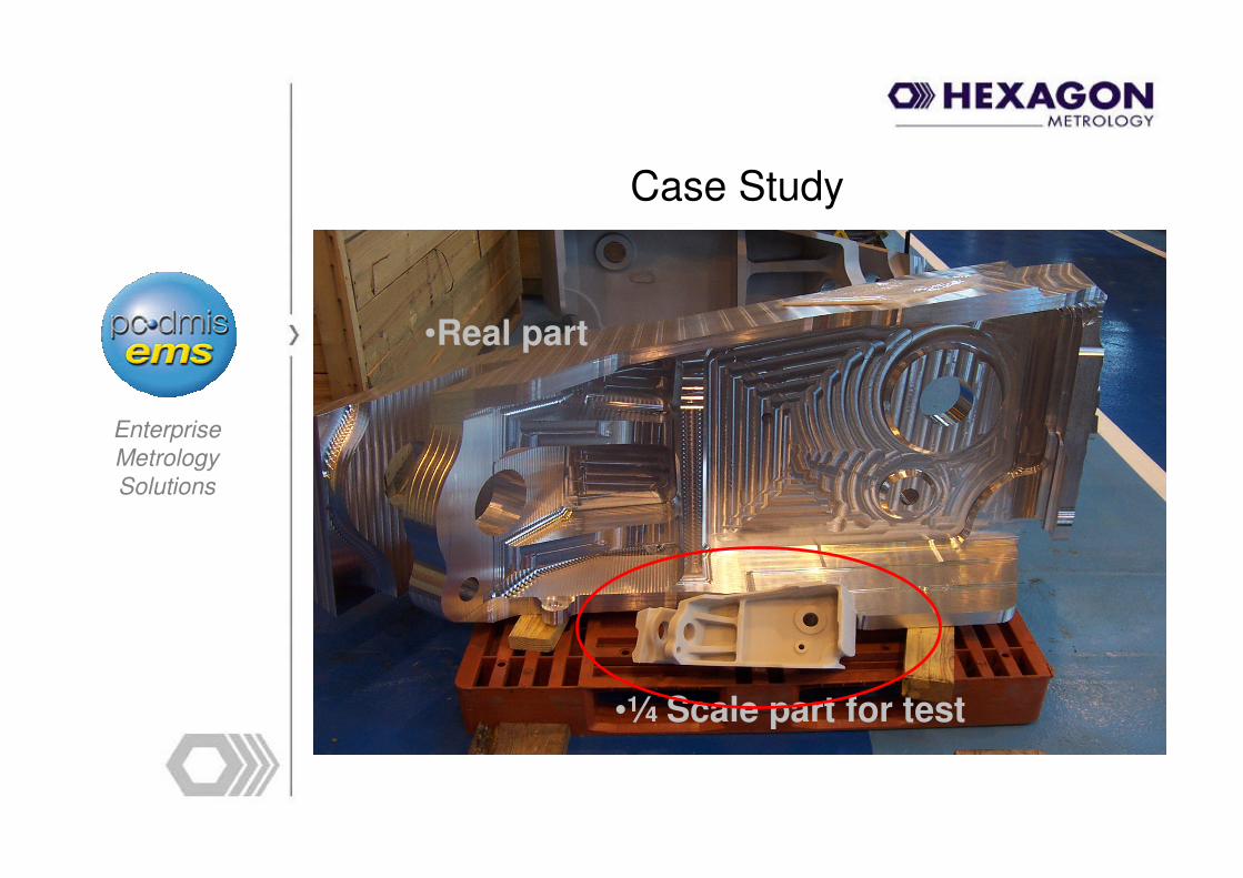
Case Study
Enterprise
Metrology
Solutions
•Real part
•¼ Scale part for test

How it looks in Catia V5
Enterprise
Metrology
Solutions
•Notice the GD&T

Now its imported into the PC-DMIS standalone Inspection Planner
Enterprise
Metrology
Solutions

One click on a GD&T callout
Enterprise
Metrology
Solutions
•Creates datum features
•Defines datums
•Creates measured feature
•Creates FCF
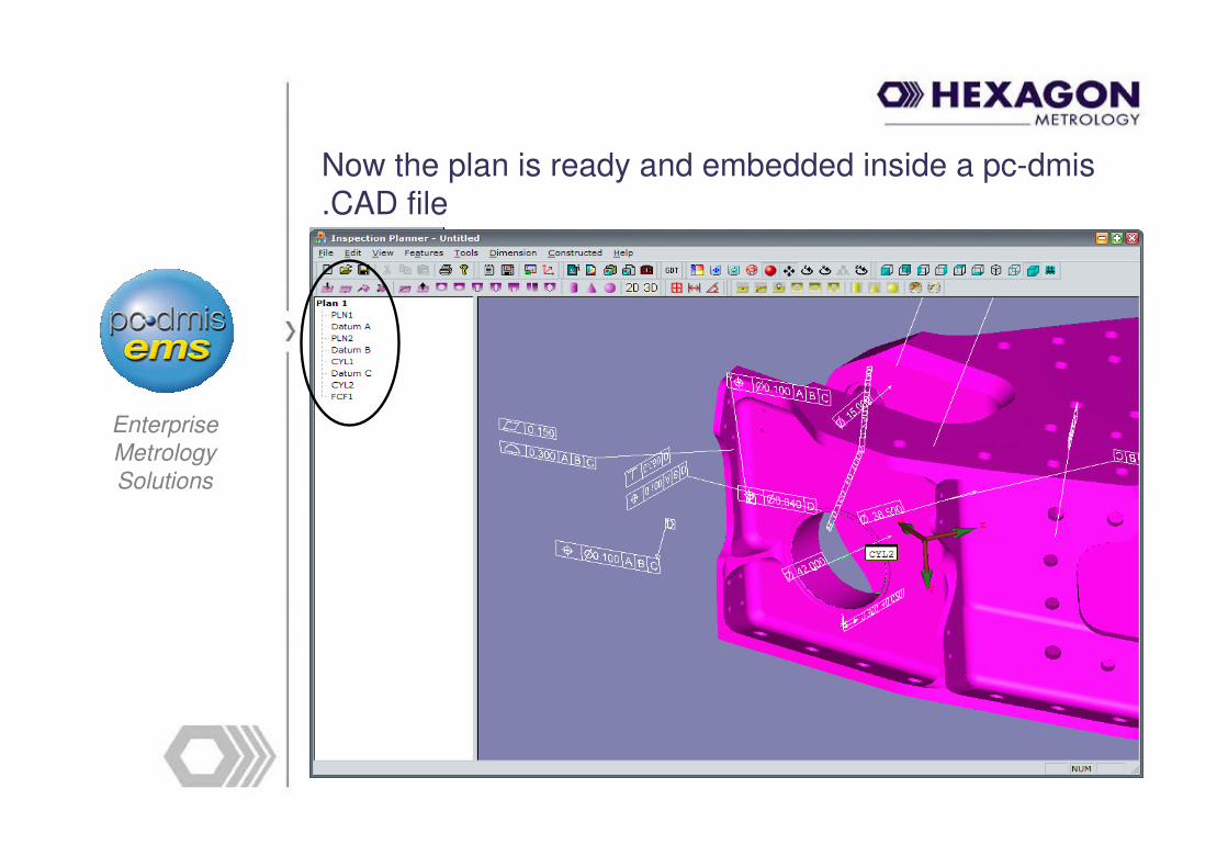
Now the plan is ready and embedded inside a pc-dmis .CAD file
Enterprise
Metrology
Solutions
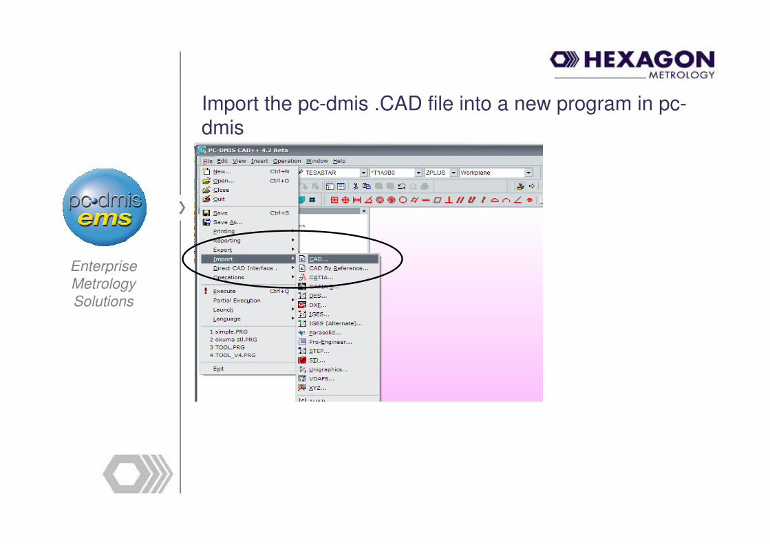
Import the pc-dmis .CAD file into a new program in pc-dmis
Enterprise
Metrology
Solutions
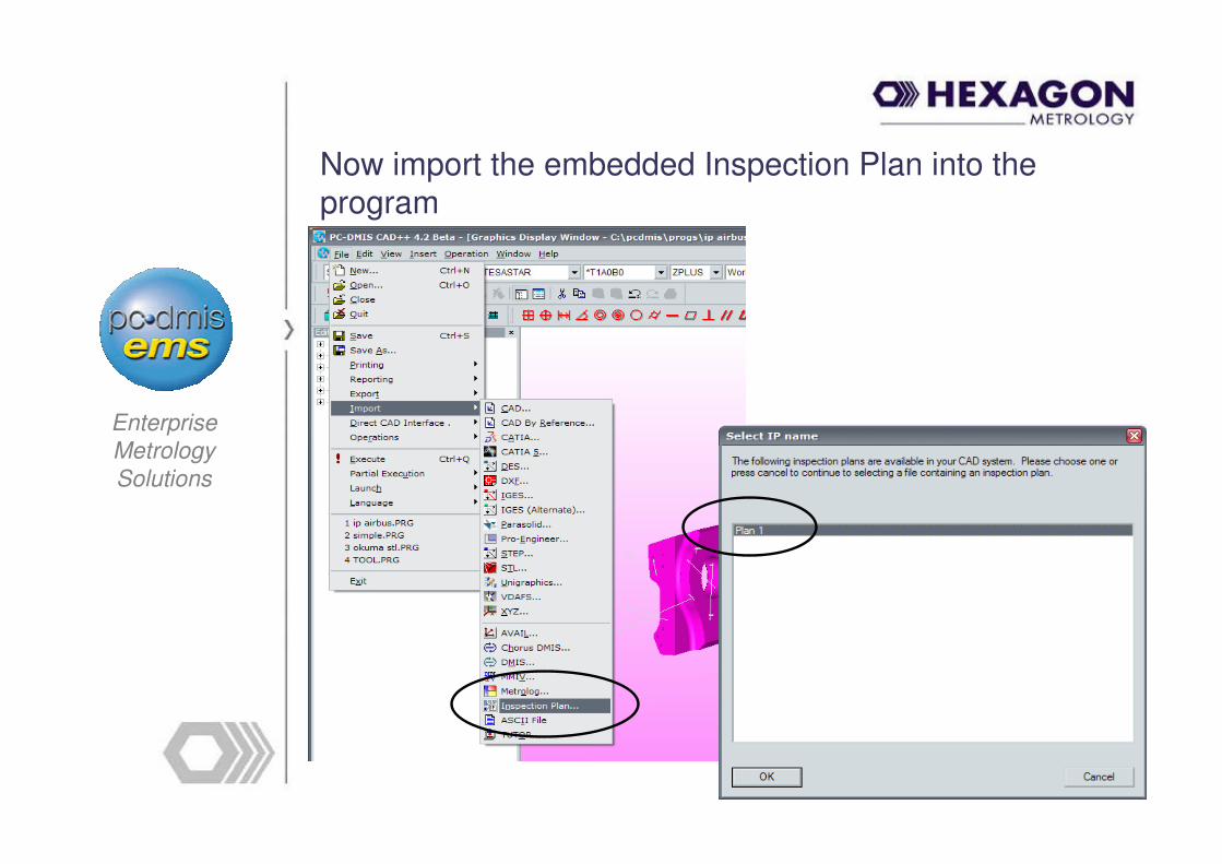
Now import the embedded Inspection Plan into the program
Enterprise
Metrology
Solutions

Now choose the “collector”
Enterprise
Metrology
Solutions
In Process
Final Component
AuditAssembly of finished
components

Then “Optimise” and “Auto create moves”
Enterprise
Metrology
Solutions
•Datums A,B &C, probe
rotation and CYL2, automatically created and
optimised

pc-dmis standard report showing FCF from “CYL2”
Enterprise
Metrology
Solutions

The process is complete
• You have just witnessed a complete paperless inspection process utilising a Catia V5 part with FT&A (GD&T).
• The plans are device independent meaning that you can use tactile probing, laser probing, portable devices, NC probes or CMM’s to actually gather the data.
• Simply open up your local version of pc-dmis that is attached to your preferred device, import the .CAD file, import your chosen plan, optimise, simulate and measure.
• The report is automatically created for you, based on the FTA embedded in the original Catia V5 part.
Enterprise
Metrology
Solutions

Moving Forward
PC-DMIS NC™
Now we have a design that incorporates information pertaining to the tolerancing and relating these dimensions
back to datums we are ready to manufacture.
Why would Metrology be concerned at this stage?
The same programming information that is used to perform the final inspection on your components can also be used to create a control plan that can be implemented during and
even before the machining processes
Moving Forward During Manufacture
PC-DMIS NC™
•PC-DMIS NC can be used to drive probing already integrated on the
machine tool
•Perform complex best fit alignment routines, fully 3-Dimensional
•Take discreet points during the machining process to verify
condition
•Measure critical features in place of hand instruments
•Automate tool wear offsets based on SPC data
•Provide graphical reports to the operator
•Save all measured information and SPC data for each stage
•Identify any problems at the source

Applications:
PC-DMIS NC™
•Align the workpiece (billet, forging, casting etc) in 3-D on the
machine tool
•Best fitting to cad model
•Automatically Update G54 work offsets
•Ensure the workpiece is in the correct position before cutting
Benefits:
•Reduce cost of highly accurate fixturing
•Accommodate variance within raw material
•Get it right first time
•Eliminate CMM parts shuffle – reduce lead time

pc-dmis EMS – total system at Okuma

Moving Forward During Manufacture
PC-DMIS Portable™
•For components that require in-process validation, either non-
machine tool based, or not suitable for NC Probing, the same
program can be used to generate routines for Portable measuring
devices
•Common report formats are provided, regardless of the collection
device used.
Composites
Moulds
Sheet Metal
Profiles
Fabrications
The Final Stages
Component
•Now the component has arrived at the point of final inspection
before despatch to a Customer, or delivery to an assembly line
•This is a really expensive time to find a non conformance
•What is the time to remanufacture from this stage?Cost to Cost to
correct ?correct ?
X100X100
•Following through with the same investment, a program to finally inspect
the component will be ready for the chosen device.
•The results format will be identical to the in-process data
•A direct before / after analysis can be made to identify any deformation or
change during the process
•Virtual Assembly can be performed prior to arrival of the parts to the
line
The Final Stages
Assembly
• It follows that during the assembly process, positional information
will be required before final fixing.
•PC-DMIS can handle not only component, but also assembly files.
•Portable devices and large volume CMM’s can be utilised to position
and verify position of components during assembly
•Any component dimensions that are questionable during assembly
can be re-measured and compared against previous data

The Final Stage
Delivery
• Product is delivered at the right time, the right cost and with the
right quality
•All dimensionally measured data is available in a common format
and can be interrogated retrospectively
•Process capability is available, allowing feedback to manufacture
and design
•“Knowledge is power”
•Correct the process to achieve capability
•Feedback to design what is attainable

Quality Through Manufacture
Thank you for your attention