qualnet 4.5.1 wireless model library - computer...
TRANSCRIPT

QualNet 4.5.1Wireless Model Library
July 2008
Scalable Network Technologies, Inc.
6100 Center Drive, Suite 1250 Los Angeles, CA 90045
Phone: 310-338-3318 Fax: 310-338-7213
http://www.scalable-networks.com http://www.qualnet.com
Copyright Information
© 2008 Scalable Network Technologies, Inc. All rights reserved.
QualNet is a registered trademark of Scalable Network Technologies, Inc.
All other trademarks and trade names used are property of their respective companies.
Scalable Network Technologies, Inc.6100 Center Drive, Suite 1250Los Angeles, CA 90045
Phone: 310-338-3318Fax: 310-338-7213
http://www.scalable-networks.comhttp://www.qualnet.com
ii QualNet 4.5.1 Wireless Model Library
Table of Conetents
802.11 MAC Protocol ...................................................................................................................... 1
802.11a/g PHY Model ................................................................................................................... 26
802.11b PHY Model ...................................................................................................................... 28
802.11e MAC Protocol .................................................................................................................. 30
802.11s MAC Protocol .................................................................................................................. 40
Abstract PHY Model...................................................................................................................... 62
Ad-Hoc On Demand Distance Vector (AODV) Routing Protocol .................................................. 63
Aloha MAC Protocol...................................................................................................................... 71
Battery Models .............................................................................................................................. 72
Bite Error Rate-based (BER) Reception Model............................................................................. 85
Bordercast Resolution Protocol (BRP).......................................................................................... 87
Cartesian Terrain Format .............................................................................................................. 88
Constant Shadowing Model .......................................................................................................... 90
Carrier Sense Multiple Access (CSMA) MAC Protocol ................................................................. 91
Digital Elevation Model (DEM) Terrain Format.............................................................................. 92
Digital Terrain Elevation (DTED) Terrain Format........................................................................... 94
Dynamic MANET On-demand (DYMO) Routing Protocol........................................................... 100
Dynamic Source Routing (DSR) Protocol ................................................................................... 109
Fast Rayleigh Fading Model ........................................................................................................111
File-based Mobility Model ........................................................................................................... 113
Fisheye State Routing Protocol................................................................................................... 115
Free-space Pathloss Model ........................................................................................................ 116
Generic MAC Protocol ................................................................................................................ 117
Group Node Placement and Mobility Models.............................................................................. 119
Intrazone Routing Protocol (IARP).............................................................................................. 124
QualNet 4.5.1 Wireless Model Library iii
Interzone Routing Protocol (IERP).............................................................................................. 125
Irregular Terrain Model (ITM) ...................................................................................................... 127
Landmark Ad Hoc Routing (LANMAR) Protocol ......................................................................... 129
Location-Aided Routing (LAR) Protocol ...................................................................................... 131
Lognormal Shadowing Model...................................................................................................... 133
Microwave Links.......................................................................................................................... 134
Mobile IPv4 ................................................................................................................................. 138
Multiple Access Collision Avoidance (MACA) MAC Protocol...................................................... 140
On-Demand Multicast Routing Protocol (ODMRP) ..................................................................... 141
Optimized Link State Routing Protocol - INRIA (OLSR-INRIA)................................................... 143
Optimized Link State Routing Protocol version 2 (OLSRv2) ....................................................... 146
Omnidirectional Antenna Model .................................................................................................. 157
Pathloss Matrix Model................................................................................................................. 158
Patterned Antenna Model ........................................................................................................... 160
Pedestrian Mobility Model ........................................................................................................... 166
Radio Energy Models.................................................................................................................. 169
Random Waypoint Mobility Model............................................................................................... 178
Rayleigh Fading Model ............................................................................................................... 179
Ricean Fading Model .................................................................................................................. 181
SNR-based Reception Model...................................................................................................... 183
Source Tree Adaptive Routing (STAR) Protocol ......................................................................... 184
Steerable Antenna Model............................................................................................................ 186
Switched-beam Antenna Model .................................................................................................. 188
Time Division Multiple Access (TDMA) MAC Protocol ................................................................ 190
Two-ray Pathloss Model.............................................................................................................. 192
Urban Terrain Data Formats........................................................................................................ 193
Weather Pattern Model ............................................................................................................... 195
Zone Routing Protocol (ZRP)...................................................................................................... 197
Appendix A - QualNet Terrain Format ........................................................................................ 199
iv QualNet 4.5.1 Wireless Model Library
802.11 MAC Protocol
802.11 MAC Protocol
The IEEE 802.11 standard defines a set of MAC and PHY specifications for wireless LAN, also known as WiFi. It was developed by the IEEE 802.11 working group. The original standard was developed in 1997. Later, several amendments have been proposed to extend 802.11 at both the MAC and physical layers to support various features such as higher bandwidth, QoS, security, etc.
IEEE 802.11 defines two different architectures, BSS (Basic Service Set) and IBSS (Independent Basic Service Set). In a BSS or Infrastructure mode, numbers of wireless stations (STAs) are associated to an AP (Access Point). All communications take place through the AP. IBSS, also known as ad-hoc mode STAs can communicate directly to each other, providing that they are within each other's transmission range.
IEEE 802.11 MAC defines two different access mechanisms, the mandatory Distributed Coordination Function (DCF) which provides distributed channel access based on CSMA/CA (Carrier Sense Multiple Access with Collision Avoidance), and the optional Point Coordination Function (PCF) which provides centrally controlled channel access through polling.
IEEE 802.11 standard defined the Power Saving (PS) Mode for decreasing the energy consumption at STA.
DCF ProcedureThe fundamental access method of the IEEE 802.11 MAC is DCF. The DCF shall be implemented in all STAs, for use within both IBSS and infrastructure network configurations. For a STA to transmit, it shall sense the medium to determine if another STA is transmitting. If the medium is not determined to be busy, the transmission may proceed.
The CSMA/CA distributed algorithm mandates that a gap of a minimum specified duration exist between contiguous frame sequences. A transmitting STA shall ensure that the medium is idle for this required duration before attempting to transmit. If the medium is determined to be busy, the STA shall defer until the end of the current transmission.
After deferral, or prior to attempting to transmit again immediately after a successful transmission, the STA shall select a random backoff interval and shall decrement the backoff interval counter while the medium is idle. A refinement of the method may be used under various circumstances to further minimize collisions-here the transmitting and receiving STA exchange short control frames [request to send (RTS) and clear to send (CTS) frames] after determining that the medium is idle and after any deferrals or backoffs, prior to data transmission.
PCF ProcedureIn the PCF procedure the access of the wireless channel is centralized by using polling based protocol controlled by the Point Coordinator. The Access points generally serve as PCs. The PCF mode provides contention free service to the wireless Stations.
In PCF mode a frame is divided into two parts, contention free period (CFP) and contention period (CP). The PC indicates the start of the contention free period by sending a beacon frame which contains the PCF related information (e.g. CFP parameter set) The CFP is repeated after a fixed interval that is CF repetition interval.
QualNet 4.5.1 Wireless Model Library 1
802.11 MAC Protocol
After sending the Beacon the PC starts polling stations one by one in the order of their association ID. In CF period, if the PC has a downlink data packet to send to the station it sends the polling packet piggybacked on the data packet and if the PC does not have any data to send then it sends only a polling packet.
If polled station has any data to send to PC then it piggybacks data on the ACK packet. If Polled station does not have data to send in the uplink then it just sends a NULL packet in response to the poll by PC.
Power Saving Mode
Power saving mode is used to reduce the energy consumption at the station (STA) node. Three distinct building blocks are provided to support power savings: a Wakeup Procedure, a Sleep Procedure, and a Power-save Poll (PS-Poll) Procedure. A station can combine these power management building blocks in various manners for different applications.
Wakeup Procedure: There are two reasons for the STA to wake up: to transmit pending data or to receive buffered data from an access point (AP). Waking up to transmit data is a straightforward operation, driven by the STA. The decision to wake up and receive data is also made by the STA after monitoring its pending data bit in a periodic beacon frame sent out by its AP. Once the STA decides to transitions from sleep mode to active mode, it notifies the AP by sending an uplink frame with the power-save (PS) bit set to active. Following such transmission, the STA remains active so the AP can send any buffered downlink frames afterward.
Sleep Procedure: Similar to the wakeup procedure, a STA in the active mode needs to complete a successful STA initiated frame exchange sequence with PS bit set to sleep to transition into the sleep mode. Following this operation, the AP buffers all the downlink frames to this STA.
PS-Poll Procedure: Instead of waiting for the AP to transmit the buffered downlink frames, a STA in sleep mode can solicit an immediate delivery from its AP by using a PS-Poll frame. Upon receiving this PS-Poll, the AP can immediately send one buffered downlink frame (immediate data response) or simply send an acknowledgement message and respond with a buffered data frame later (delayed data response). For the immediate data response case, the STA can stay in the sleep state after finishing this frame exchange since there is no need for the STA to transition to the active state given that the AP can only send a buffered downlink frame in response to the PS-poll from the STA. For the delayed data response case, the STA has to transition to the active state until receiving a downlink frame from the AP.
Note: There are no specific guidelines on how to adjust these parameters, because other parameters need to be changed to keep the slot time (10 microseconds) the same.
2 QualNet 4.5.1 Wireless Model Library
802.11 MAC Protocol
Command Line Configuration
To specify 802.11 MAC as the MAC protocol, include the following parameter in the scenario configuration (.config) file:
MAC-PROTOCOL MACDOT11
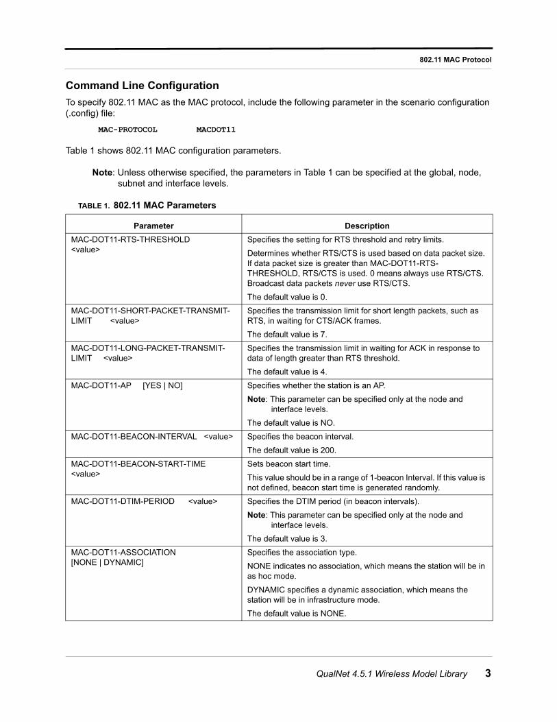
Table 1 shows 802.11 MAC configuration parameters.
Note: Unless otherwise specified, the parameters in Table 1 can be specified at the global, node, subnet and interface levels.
TABLE 1. 802.11 MAC Parameters
Parameter Description
MAC-DOT11-RTS-THRESHOLD <value>
Specifies the setting for RTS threshold and retry limits.
Determines whether RTS/CTS is used based on data packet size. If data packet size is greater than MAC-DOT11-RTS-THRESHOLD, RTS/CTS is used. 0 means always use RTS/CTS. Broadcast data packets never use RTS/CTS.
The default value is 0.
MAC-DOT11-SHORT-PACKET-TRANSMIT-LIMIT <value>
Specifies the transmission limit for short length packets, such as RTS, in waiting for CTS/ACK frames.
The default value is 7.
MAC-DOT11-LONG-PACKET-TRANSMIT-LIMIT <value>
Specifies the transmission limit in waiting for ACK in response to data of length greater than RTS threshold.
The default value is 4.
MAC-DOT11-AP [YES | NO] Specifies whether the station is an AP.
Note: This parameter can be specified only at the node and interface levels.
The default value is NO.
MAC-DOT11-BEACON-INTERVAL <value> Specifies the beacon interval.
The default value is 200.
MAC-DOT11-BEACON-START-TIME <value>
Sets beacon start time.
This value should be in a range of 1-beacon Interval. If this value is not defined, beacon start time is generated randomly.
MAC-DOT11-DTIM-PERIOD <value> Specifies the DTIM period (in beacon intervals).
Note: This parameter can be specified only at the node and interface levels.
The default value is 3.
MAC-DOT11-ASSOCIATION [NONE | DYNAMIC]
Specifies the association type.
NONE indicates no association, which means the station will be in as hoc mode.
DYNAMIC specifies a dynamic association, which means the station will be in infrastructure mode.
The default value is NONE.
QualNet 4.5.1 Wireless Model Library 3
802.11 MAC Protocol
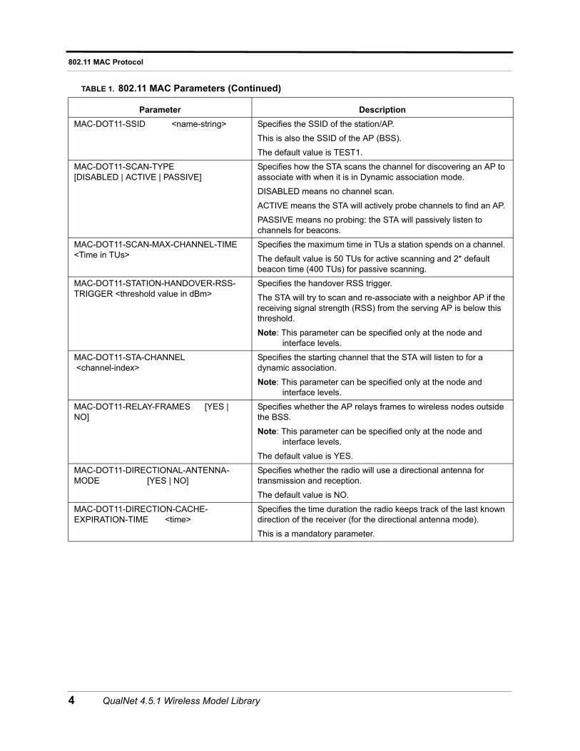
MAC-DOT11-SSID <name-string> Specifies the SSID of the station/AP.
This is also the SSID of the AP (BSS).
The default value is TEST1.
MAC-DOT11-SCAN-TYPE [DISABLED | ACTIVE | PASSIVE]
Specifies how the STA scans the channel for discovering an AP to associate with when it is in Dynamic association mode.
DISABLED means no channel scan.
ACTIVE means the STA will actively probe channels to find an AP.
PASSIVE means no probing: the STA will passively listen to channels for beacons.
MAC-DOT11-SCAN-MAX-CHANNEL-TIME <Time in TUs>
Specifies the maximum time in TUs a station spends on a channel.
The default value is 50 TUs for active scanning and 2* default beacon time (400 TUs) for passive scanning.
MAC-DOT11-STATION-HANDOVER-RSS-TRIGGER <threshold value in dBm>
Specifies the handover RSS trigger.
The STA will try to scan and re-associate with a neighbor AP if the receiving signal strength (RSS) from the serving AP is below this threshold.
Note: This parameter can be specified only at the node and interface levels.
MAC-DOT11-STA-CHANNEL <channel-index>
Specifies the starting channel that the STA will listen to for a dynamic association.
Note: This parameter can be specified only at the node and interface levels.
MAC-DOT11-RELAY-FRAMES [YES | NO]
Specifies whether the AP relays frames to wireless nodes outside the BSS.
Note: This parameter can be specified only at the node and interface levels.
The default value is YES.
MAC-DOT11-DIRECTIONAL-ANTENNA-MODE [YES | NO]
Specifies whether the radio will use a directional antenna for transmission and reception.
The default value is NO.
MAC-DOT11-DIRECTION-CACHE-EXPIRATION-TIME <time>
Specifies the time duration the radio keeps track of the last known direction of the receiver (for the directional antenna mode).
This is a mandatory parameter.
TABLE 1. 802.11 MAC Parameters (Continued)
Parameter Description
4 QualNet 4.5.1 Wireless Model Library
802.11 MAC Protocol
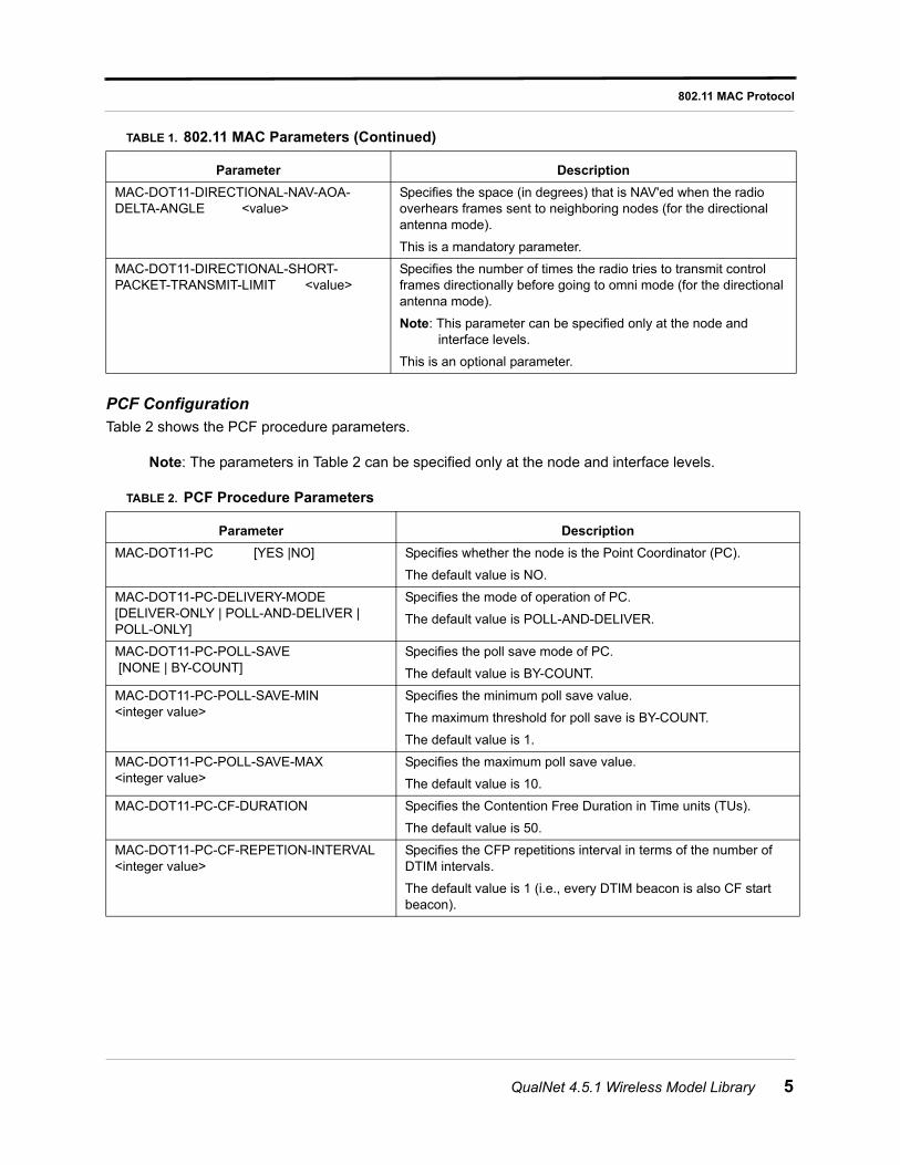
PCF ConfigurationTable 2 shows the PCF procedure parameters.
Note: The parameters in Table 2 can be specified only at the node and interface levels.
MAC-DOT11-DIRECTIONAL-NAV-AOA-DELTA-ANGLE <value>
Specifies the space (in degrees) that is NAV'ed when the radio overhears frames sent to neighboring nodes (for the directional antenna mode).
This is a mandatory parameter.
MAC-DOT11-DIRECTIONAL-SHORT-PACKET-TRANSMIT-LIMIT <value>
Specifies the number of times the radio tries to transmit control frames directionally before going to omni mode (for the directional antenna mode).
Note: This parameter can be specified only at the node and interface levels.
This is an optional parameter.
TABLE 2. PCF Procedure Parameters
Parameter Description
MAC-DOT11-PC [YES |NO] Specifies whether the node is the Point Coordinator (PC).
The default value is NO.
MAC-DOT11-PC-DELIVERY-MODE[DELIVER-ONLY | POLL-AND-DELIVER | POLL-ONLY]
Specifies the mode of operation of PC.
The default value is POLL-AND-DELIVER.
MAC-DOT11-PC-POLL-SAVE [NONE | BY-COUNT]
Specifies the poll save mode of PC.
The default value is BY-COUNT.
MAC-DOT11-PC-POLL-SAVE-MIN <integer value>
Specifies the minimum poll save value.
The maximum threshold for poll save is BY-COUNT.
The default value is 1.
MAC-DOT11-PC-POLL-SAVE-MAX <integer value>
Specifies the maximum poll save value.
The default value is 10.
MAC-DOT11-PC-CF-DURATION Specifies the Contention Free Duration in Time units (TUs).
The default value is 50.
MAC-DOT11-PC-CF-REPETION-INTERVAL <integer value>
Specifies the CFP repetitions interval in terms of the number of DTIM intervals.
The default value is 1 (i.e., every DTIM beacon is also CF start beacon).
TABLE 1. 802.11 MAC Parameters (Continued)
Parameter Description
QualNet 4.5.1 Wireless Model Library 5
802.11 MAC Protocol
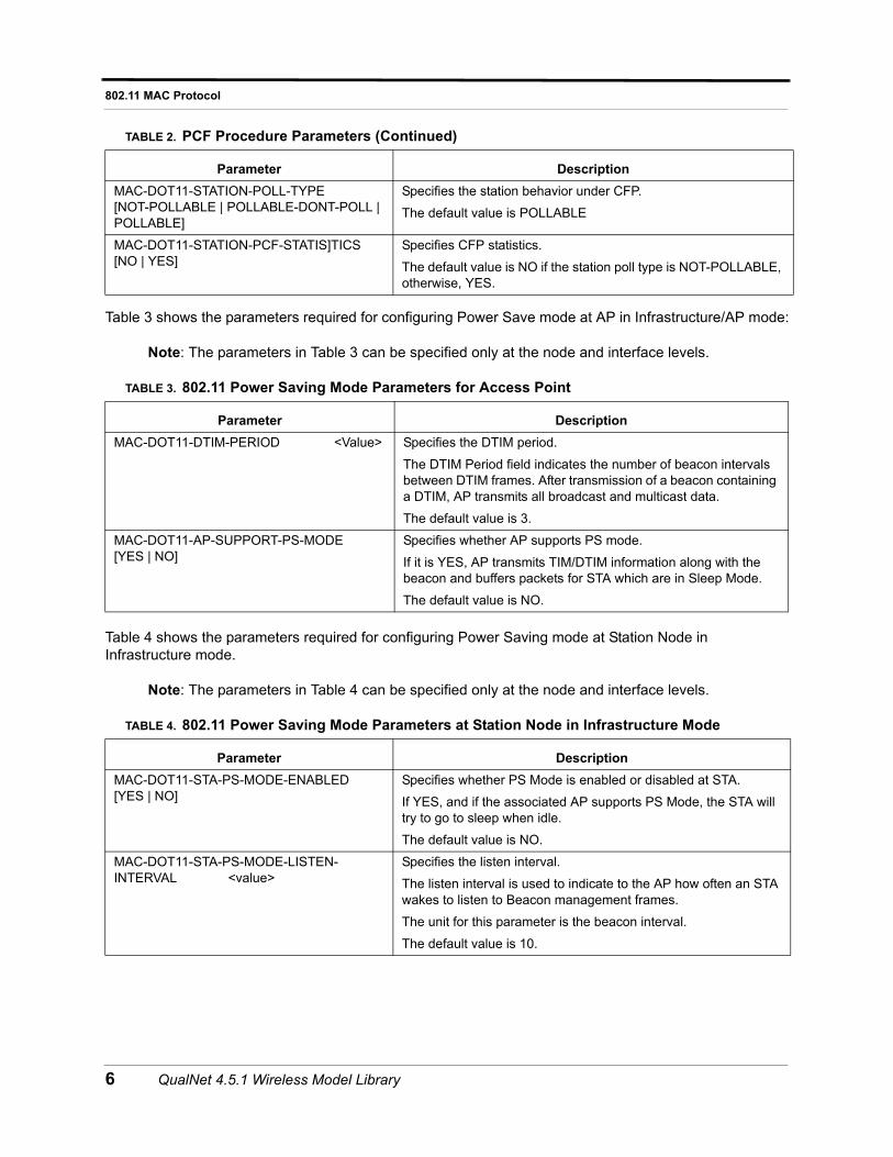
Table 3 shows the parameters required for configuring Power Save mode at AP in Infrastructure/AP mode:
Note: The parameters in Table 3 can be specified only at the node and interface levels.
Table 4 shows the parameters required for configuring Power Saving mode at Station Node in Infrastructure mode.
Note: The parameters in Table 4 can be specified only at the node and interface levels.
MAC-DOT11-STATION-POLL-TYPE [NOT-POLLABLE | POLLABLE-DONT-POLL | POLLABLE]
Specifies the station behavior under CFP.
The default value is POLLABLE
MAC-DOT11-STATION-PCF-STATIS]TICS [NO | YES]
Specifies CFP statistics.
The default value is NO if the station poll type is NOT-POLLABLE, otherwise, YES.
TABLE 3. 802.11 Power Saving Mode Parameters for Access Point
Parameter Description
MAC-DOT11-DTIM-PERIOD <Value> Specifies the DTIM period.
The DTIM Period field indicates the number of beacon intervals between DTIM frames. After transmission of a beacon containing a DTIM, AP transmits all broadcast and multicast data.
The default value is 3.
MAC-DOT11-AP-SUPPORT-PS-MODE [YES | NO]
Specifies whether AP supports PS mode.
If it is YES, AP transmits TIM/DTIM information along with the beacon and buffers packets for STA which are in Sleep Mode.
The default value is NO.
TABLE 4. 802.11 Power Saving Mode Parameters at Station Node in Infrastructure Mode
Parameter Description
MAC-DOT11-STA-PS-MODE-ENABLED [YES | NO]
Specifies whether PS Mode is enabled or disabled at STA.
If YES, and if the associated AP supports PS Mode, the STA will try to go to sleep when idle.
The default value is NO.
MAC-DOT11-STA-PS-MODE-LISTEN-INTERVAL <value>
Specifies the listen interval.
The listen interval is used to indicate to the AP how often an STA wakes to listen to Beacon management frames.
The unit for this parameter is the beacon interval.
The default value is 10.
TABLE 2. PCF Procedure Parameters (Continued)
Parameter Description
6 QualNet 4.5.1 Wireless Model Library
802.11 MAC Protocol
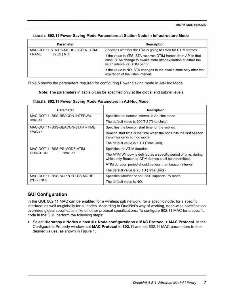
Table 5 shows the parameters required for configuring Power Saving mode in Ad-Hoc Mode.
Note: The parameters in Table 5 can be specified only at the global and subnet levels.
GUI Configuration
In the GUI, 802.11 MAC can be enabled for a wireless sub network, for a specific node, for a specific interface, as well as globally for all nodes. According to QualNet’s way of working, node-wise specification overrides global specification like all other protocol specifications. To configure 802.11 MAC for a specific node in the GUI, perform the following steps:
1. Select Hierarchy > Nodes > host # > Node configurations > MAC Protocol > MAC Protocol. In the Configurable Property window, set MAC Protocol to 802.11 and set 802.11 MAC parameters to their desired values, as shown in Figure 1.
MAC-DOT11-STA-PS-MODE-LISTEN-DTIM-FRAME [YES | NO]
Specifies whether the STA is going to listen for DTIM frames.
If the value is YES, STA receives DTIM frames from AP. In that case, STAs change to awake state after expiration of either the listen interval or DTIM period.
If the value is NO, STA changes to the awake state only after the expiration of the listen interval.
TABLE 5. 802.11 Power Saving Mode Parameters in Ad-Hoc Mode
Parameter Description
MAC-DOT11-IBSS-BEACON-INTERVAL <Value>
Specifies the beacon interval in Ad-Hoc mode.
The default value is 200 TU (Time Units).
MAC-DOT11-IBSS-BEACON-START-TIME <Value>
Specifies the beacon start time for the subnet.
Beacon start time is the time when the node hits the first beacon transmission in ad hoc mode.
The default value is 1 TU (Time Unit).
MAC-DOT11-IBSS-PS-MODE-ATIM-DURATION <Value>
Specifies the ATIM duration.
The ATIM Window is defined as a specific period of time, during which only Beacon or ATIM frames shall be transmitted.
ATIM duration period should be less than beacon interval.
The default value is 20 TU (Time Units).
MAC-DOT11-IBSS-SUPPORT-PS-MODE [YES | NO]
Specifies whether or not IBSS supports PS mode.
The default value is NO.
TABLE 4. 802.11 Power Saving Mode Parameters at Station Node in Infrastructure Mode
Parameter Description
QualNet 4.5.1 Wireless Model Library 7
802.11 MAC Protocol
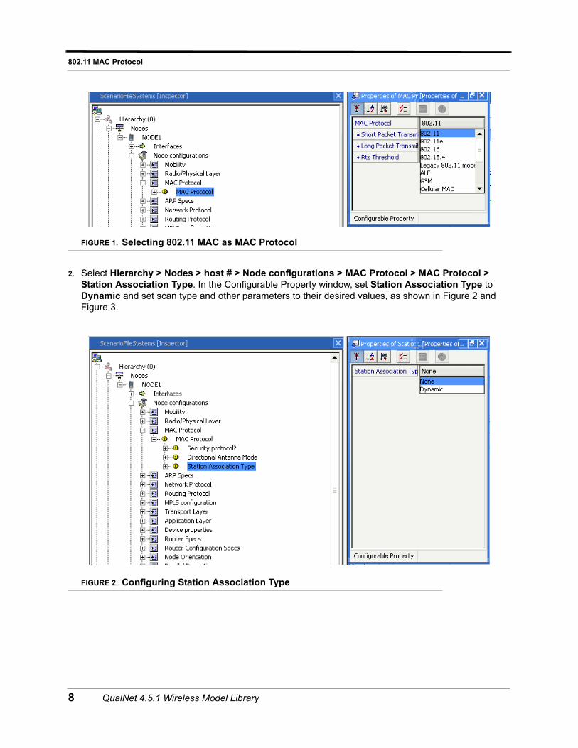
FIGURE 1. Selecting 802.11 MAC as MAC Protocol
2. Select Hierarchy > Nodes > host # > Node configurations > MAC Protocol > MAC Protocol > Station Association Type. In the Configurable Property window, set Station Association Type to Dynamic and set scan type and other parameters to their desired values, as shown in Figure 2 and Figure 3.
FIGURE 2. Configuring Station Association Type
8 QualNet 4.5.1 Wireless Model Library
802.11 MAC Protocol
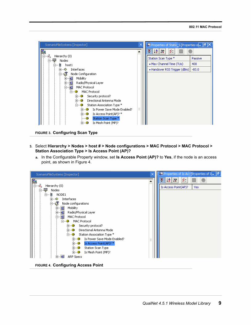
FIGURE 3. Configuring Scan Type
3. Select Hierarchy > Nodes > host # > Node configurations > MAC Protocol > MAC Protocol > Station Association Type > Is Access Point (AP)?
a. In the Configurable Property window, set Is Access Point (AP)? to Yes, if the node is an access point, as shown in Figure 4.
FIGURE 4. Configuring Access Point
QualNet 4.5.1 Wireless Model Library 9
802.11 MAC Protocol
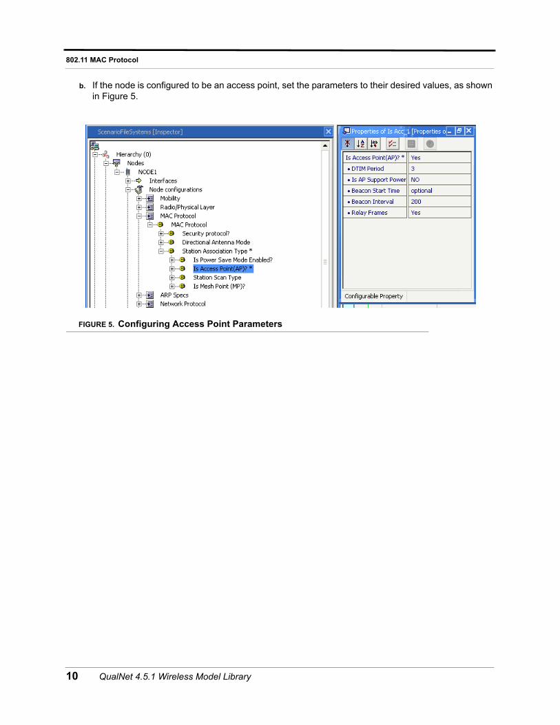
b. If the node is configured to be an access point, set the parameters to their desired values, as shown in Figure 5.
FIGURE 5. Configuring Access Point Parameters
10 QualNet 4.5.1 Wireless Model Library
802.11 MAC Protocol
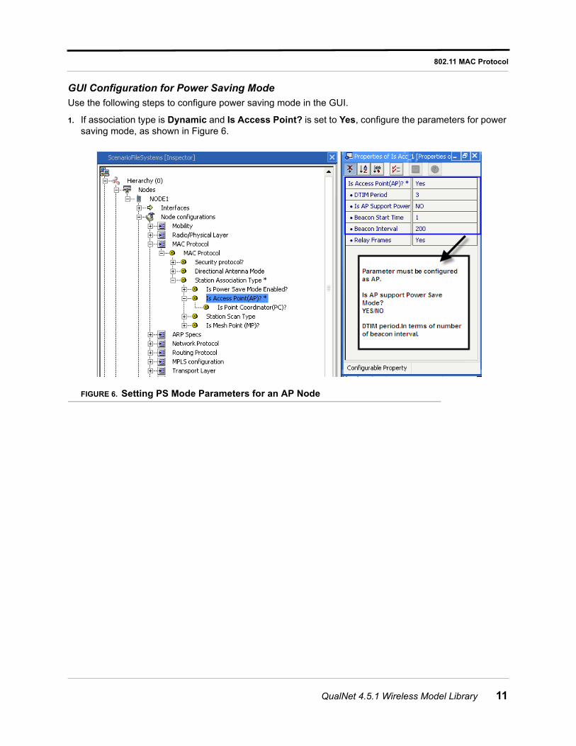
GUI Configuration for Power Saving Mode
Use the following steps to configure power saving mode in the GUI.
1. If association type is Dynamic and Is Access Point? is set to Yes, configure the parameters for power saving mode, as shown in Figure 6.
FIGURE 6. Setting PS Mode Parameters for an AP Node
QualNet 4.5.1 Wireless Model Library 11
802.11 MAC Protocol
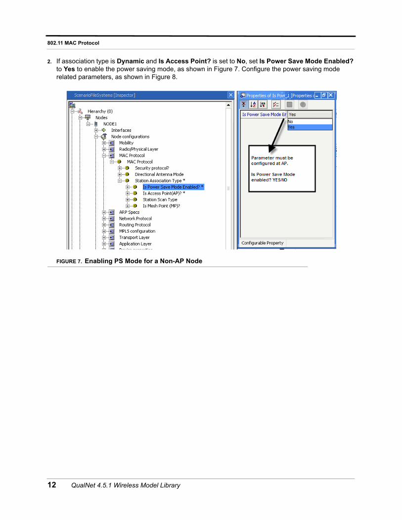
2. If association type is Dynamic and Is Access Point? is set to No, set Is Power Save Mode Enabled? to Yes to enable the power saving mode, as shown in Figure 7. Configure the power saving mode related parameters, as shown in Figure 8.
FIGURE 7. Enabling PS Mode for a Non-AP Node
12 QualNet 4.5.1 Wireless Model Library
802.11 MAC Protocol
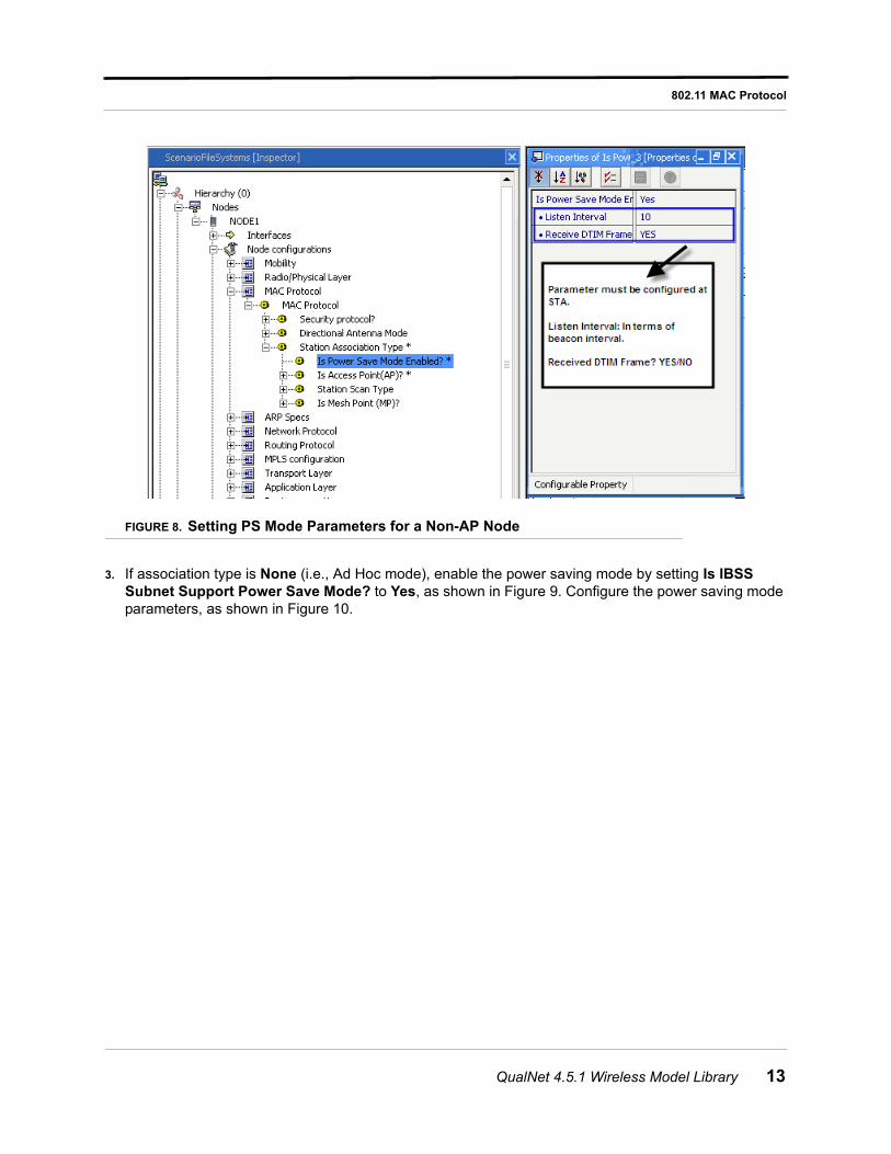
FIGURE 8. Setting PS Mode Parameters for a Non-AP Node
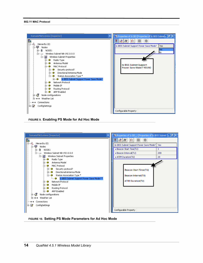
3. If association type is None (i.e., Ad Hoc mode), enable the power saving mode by setting Is IBSS Subnet Support Power Save Mode? to Yes, as shown in Figure 9. Configure the power saving mode parameters, as shown in Figure 10.
QualNet 4.5.1 Wireless Model Library 13
802.11 MAC Protocol
FIGURE 9. Enabling PS Mode for Ad Hoc Mode
FIGURE 10. Setting PS Mode Parameters for Ad Hoc Mode
14 QualNet 4.5.1 Wireless Model Library
802.11 MAC Protocol
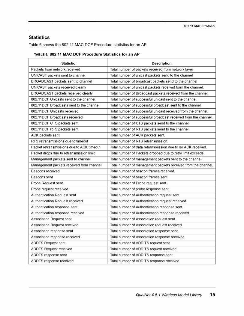
Statistics
Table 6 shows the 802.11 MAC DCF Procedure statistics for an AP.
TABLE 6. 802.11 MAC DCF Procedure Statistics for an AP
Statistic Description
Packets from network received Total number of packets received from network layer
UNICAST packets sent to channel Total number of unicast packets send to the channel
BROADCAST packets sent to channel Total number of broadcast packets send to the channel
UNICAST packets received clearly Total number of unicast packets received form the channel.
BROADCAST packets received clearly Total number of Broadcast packets received from the channel.
802.11DCF Unicasts sent to the channel Total number of successful unicast sent to the channel.
802.11DCF Broadcasts sent to the channel Total number of successful broadcast sent to the channel.
802.11DCF Unicasts received Total number of successful unicast received from the channel.
802.11DCF Broadcasts received Total number of successful broadcast received from the channel.
802.11DCF CTS packets sent Total number of CTS packets send to the channel
802.11DCF RTS packets sent Total number of RTS packets send to the channel
ACK packets sent Total number of ACK packets sent.
RTS retransmissions due to timeout Total number of RTS retransmission.
Packet retransmissions due to ACK timeout Total number of data retransmission due to no ACK received.
Packet drops due to retransmission limit Total number of Packets dropped due to retry limit exceeds.
Management packets sent to channel Total number of management packets sent to the channel.
Management packets received from channel Total number of management packets received from the channel.
Beacons received Total number of beacon frames received.
Beacons sent Total number of beacon frames sent.
Probe Request sent Total number of Probe request sent.
Probe request received Total number of probe response sent.
Authentication Request sent Total number of Authentication request sent.
Authentication Request received Total number of Authentication request received.
Authentication response sent Total number of Authentication response sent.
Authentication response received Total number of Authentication response received.
Association Request sent Total number of Association request sent.
Association Request received Total number of Association request received.
Association response sent Total number of Association response sent.
Association response received Total number of Association response received.
ADDTS Request sent Total number of ADD TS request sent.
ADDTS Request received Total number of ADD TS request received.
ADDTS response sent Total number of ADD TS response sent.
ADDTS response received Total number of ADD TS response received.
QualNet 4.5.1 Wireless Model Library 15

802.11 MAC Protocol
Table 7 shows the 802.11 MAC PCF Procedure statistics for a PC.
Table 8 shows the 802.11 MAC statistics for a STA.
Table 9 shows the 802.11 MAC power saving related statistics for STAs in infrastructure mode.
TABLE 7. 802.11 MAC PCF Procedure Statistics for a PC
Statistic Description
Unicasts sent and Acked Total Number of Unicasts sent and acknowledged from Channel
Broadcasts sent Total Number of Broadcasts sent by PC in Channel
Unicasts received Total Number of Unicasts received from channel
Broadcasts received Total Number of Broadcasts received from Channel
Data-Polls transmitted Total Number of Data-Polls transmitted
Polls transmitted Total Number of Polls transmitted
Data packets transmitted Total Number of Data packets transmitted
Data packets received Total Number of Data packets received
NullData received Total Number of Null Data received
CF Ends transmitted Total Number of CF Ends transmitted
CF Ends received Total Number of CF Ends received
TABLE 8. 802.11 MAC Statistics for a STA
Statistic Description
Unicasts sent and Acked Total Number of Unicasts sent and acknowledged from channel
Unicasts received Total Number of Unicasts received from channel
Broadcasts received Total Number of Broadcasts received from channel
Data packets transmitted Total Number of Data packets transmitted to channel
NullData transmitted Total Number of Null Data transmitted to the channel
Data-Polls received Total Number of Data-Polls received
Polls received Total Number of Polls received
Data packets received Total Number of Data packets received
Beacons received Total Number of Beacons received
CF Ends Received Total Number of CF Ends Received
CF Ends transmitted Total Number of CF Ends transmitted
TABLE 9. 802.11 MAC Power Saving Related Statistics for STAs in Infrastructure Mode
Statistic Description
PS Poll Requests Sent Total number of PS poll frames sent
PS Mode DTIM Frames Received Total Number of DTIM frames received at STAs from AP
PS Mode TIM Frames Received Total Number of TIM frames received at STAs from AP
16 QualNet 4.5.1 Wireless Model Library
802.11 MAC Protocol
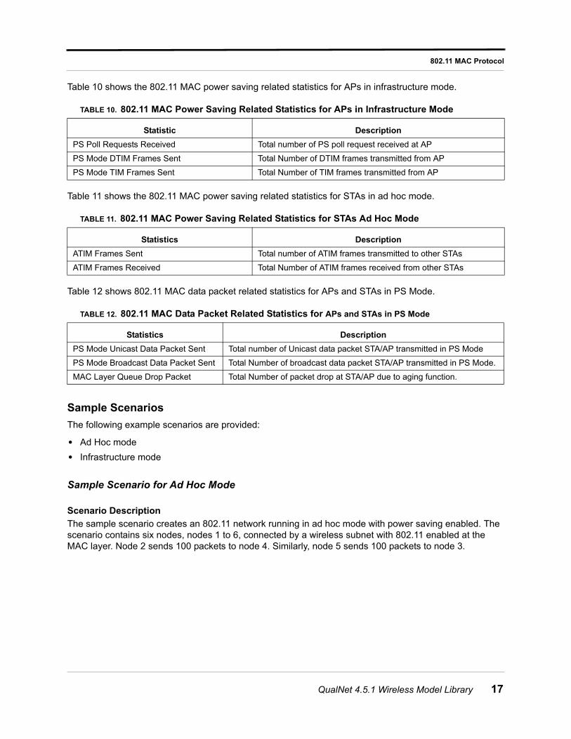
Table 10 shows the 802.11 MAC power saving related statistics for APs in infrastructure mode.
Table 11 shows the 802.11 MAC power saving related statistics for STAs in ad hoc mode.
Table 12 shows 802.11 MAC data packet related statistics for APs and STAs in PS Mode.
Sample Scenarios
The following example scenarios are provided:
• Ad Hoc mode
• Infrastructure mode
Sample Scenario for Ad Hoc Mode
Scenario Description
The sample scenario creates an 802.11 network running in ad hoc mode with power saving enabled. The scenario contains six nodes, nodes 1 to 6, connected by a wireless subnet with 802.11 enabled at the MAC layer. Node 2 sends 100 packets to node 4. Similarly, node 5 sends 100 packets to node 3.
TABLE 10. 802.11 MAC Power Saving Related Statistics for APs in Infrastructure Mode
Statistic Description
PS Poll Requests Received Total number of PS poll request received at AP
PS Mode DTIM Frames Sent Total Number of DTIM frames transmitted from AP
PS Mode TIM Frames Sent Total Number of TIM frames transmitted from AP
TABLE 11. 802.11 MAC Power Saving Related Statistics for STAs Ad Hoc Mode
Statistics Description
ATIM Frames Sent Total number of ATIM frames transmitted to other STAs
ATIM Frames Received Total Number of ATIM frames received from other STAs
TABLE 12. 802.11 MAC Data Packet Related Statistics for APs and STAs in PS Mode
Statistics Description
PS Mode Unicast Data Packet Sent Total number of Unicast data packet STA/AP transmitted in PS Mode
PS Mode Broadcast Data Packet Sent Total Number of broadcast data packet STA/AP transmitted in PS Mode.
MAC Layer Queue Drop Packet Total Number of packet drop at STA/AP due to aging function.
QualNet 4.5.1 Wireless Model Library 17
802.11 MAC Protocol
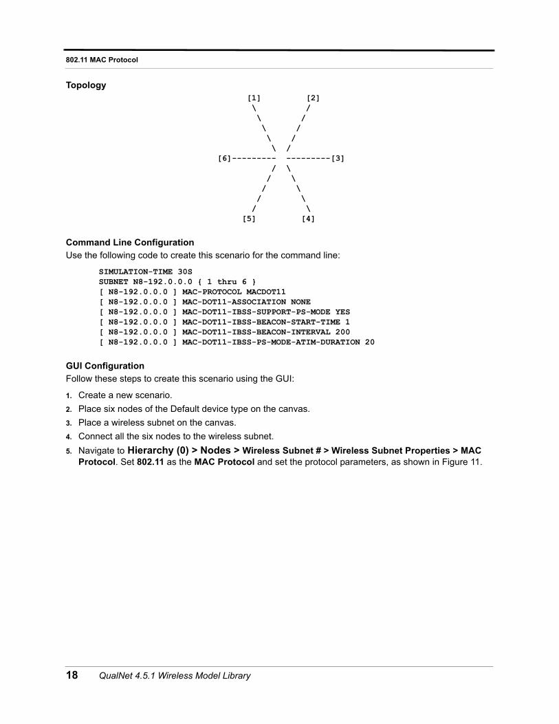
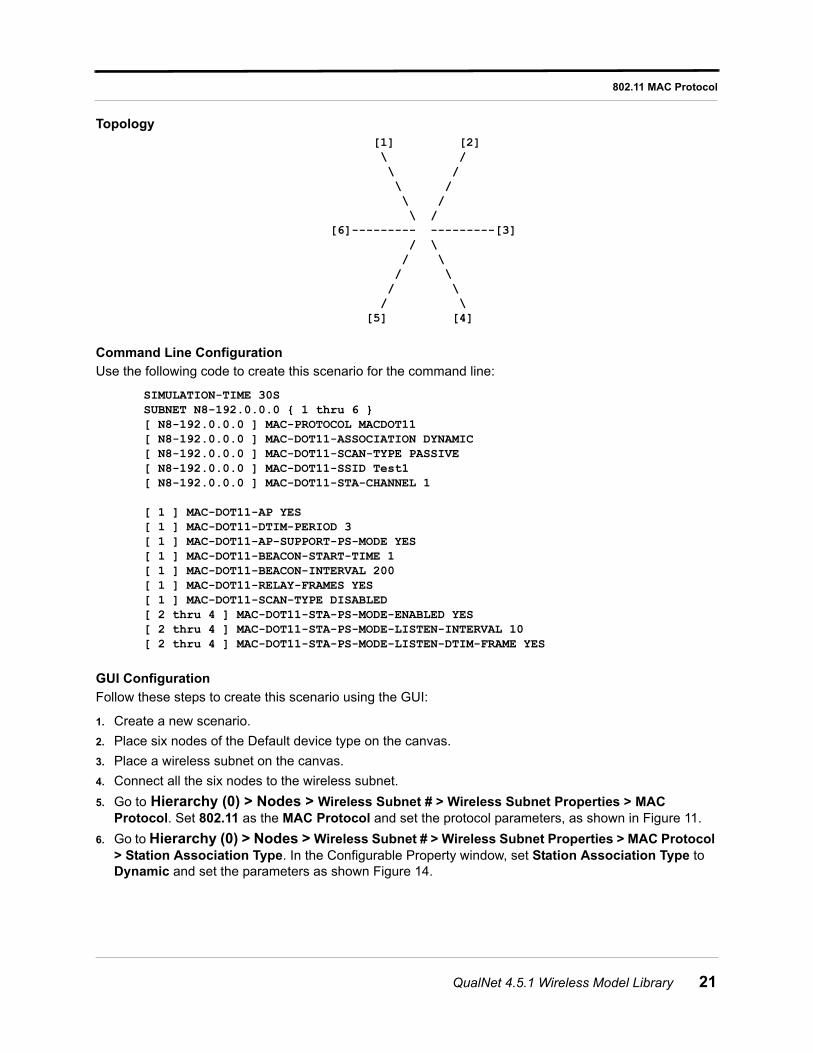
Topology [1] [2] \ / \ / \ / \ / \ / [6]--------- ---------[3] / \ / \ / \ / \ / \ [5] [4]
Command Line Configuration
Use the following code to create this scenario for the command line:
SIMULATION-TIME 30SSUBNET N8-192.0.0.0 { 1 thru 6 }[ N8-192.0.0.0 ] MAC-PROTOCOL MACDOT11[ N8-192.0.0.0 ] MAC-DOT11-ASSOCIATION NONE[ N8-192.0.0.0 ] MAC-DOT11-IBSS-SUPPORT-PS-MODE YES[ N8-192.0.0.0 ] MAC-DOT11-IBSS-BEACON-START-TIME 1[ N8-192.0.0.0 ] MAC-DOT11-IBSS-BEACON-INTERVAL 200[ N8-192.0.0.0 ] MAC-DOT11-IBSS-PS-MODE-ATIM-DURATION 20
GUI Configuration
Follow these steps to create this scenario using the GUI:
1. Create a new scenario.
2. Place six nodes of the Default device type on the canvas.
3. Place a wireless subnet on the canvas.
4. Connect all the six nodes to the wireless subnet.
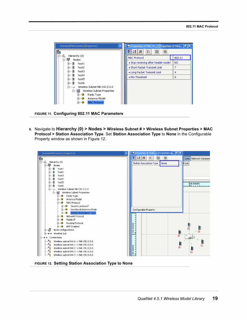
5. Navigate to Hierarchy (0) > Nodes > Wireless Subnet # > Wireless Subnet Properties > MAC Protocol. Set 802.11 as the MAC Protocol and set the protocol parameters, as shown in Figure 11.
18 QualNet 4.5.1 Wireless Model Library
802.11 MAC Protocol
FIGURE 11. Configuring 802.11 MAC Parameters
6. Navigate to Hierarchy (0) > Nodes > Wireless Subnet # > Wireless Subnet Properties > MAC Protocol > Station Association Type. Set Station Association Type to None in the Configurable Property window as shown in Figure 12.
FIGURE 12. Setting Station Association Type to None
QualNet 4.5.1 Wireless Model Library 19
802.11 MAC Protocol
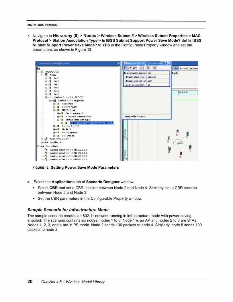
7. Navigate to Hierarchy (0) > Nodes > Wireless Subnet # > Wireless Subnet Properties > MAC Protocol > Station Association Type > Is IBSS Subnet Support Power Save Mode? Set Is IBSS Subnet Support Power Save Mode? to YES in the Configurable Property window and set the parameters, as shown in Figure 13.
FIGURE 13. Setting Power Save Mode Parameters
8. Select the Applications tab of Scenario Designer window.
• Select CBR and set a CBR session between Node 2 and Node 4. Similarly, set a CBR session between Node 5 and Node 3.
• Set the CBR parameters in the Configurable Property window.
Sample Scenario for Infrastructure Mode
The sample scenario creates an 802.11 network running in infrastructure mode with power saving enabled. The scenario contains six nodes, nodes 1 to 6. Node 1 is an AP and nodes 2 to 6 are STAs. Nodes 1, 2, 3, and 4 are in PS mode. Node 2 sends 100 packets to node 4. Similarly, node 5 sends 100 packets to node 3.
20 QualNet 4.5.1 Wireless Model Library
802.11 MAC Protocol
Topology [1] [2] \ / \ / \ / \ / \ / [6]--------- ---------[3] / \ / \ / \ / \ / \ [5] [4]
Command Line Configuration
Use the following code to create this scenario for the command line:
SIMULATION-TIME 30SSUBNET N8-192.0.0.0 { 1 thru 6 }[ N8-192.0.0.0 ] MAC-PROTOCOL MACDOT11[ N8-192.0.0.0 ] MAC-DOT11-ASSOCIATION DYNAMIC[ N8-192.0.0.0 ] MAC-DOT11-SCAN-TYPE PASSIVE[ N8-192.0.0.0 ] MAC-DOT11-SSID Test1[ N8-192.0.0.0 ] MAC-DOT11-STA-CHANNEL 1
[ 1 ] MAC-DOT11-AP YES[ 1 ] MAC-DOT11-DTIM-PERIOD 3[ 1 ] MAC-DOT11-AP-SUPPORT-PS-MODE YES[ 1 ] MAC-DOT11-BEACON-START-TIME 1[ 1 ] MAC-DOT11-BEACON-INTERVAL 200[ 1 ] MAC-DOT11-RELAY-FRAMES YES[ 1 ] MAC-DOT11-SCAN-TYPE DISABLED[ 2 thru 4 ] MAC-DOT11-STA-PS-MODE-ENABLED YES[ 2 thru 4 ] MAC-DOT11-STA-PS-MODE-LISTEN-INTERVAL 10[ 2 thru 4 ] MAC-DOT11-STA-PS-MODE-LISTEN-DTIM-FRAME YES
GUI Configuration
Follow these steps to create this scenario using the GUI:
1. Create a new scenario.
2. Place six nodes of the Default device type on the canvas.
3. Place a wireless subnet on the canvas.
4. Connect all the six nodes to the wireless subnet.
5. Go to Hierarchy (0) > Nodes > Wireless Subnet # > Wireless Subnet Properties > MAC Protocol. Set 802.11 as the MAC Protocol and set the protocol parameters, as shown in Figure 11.
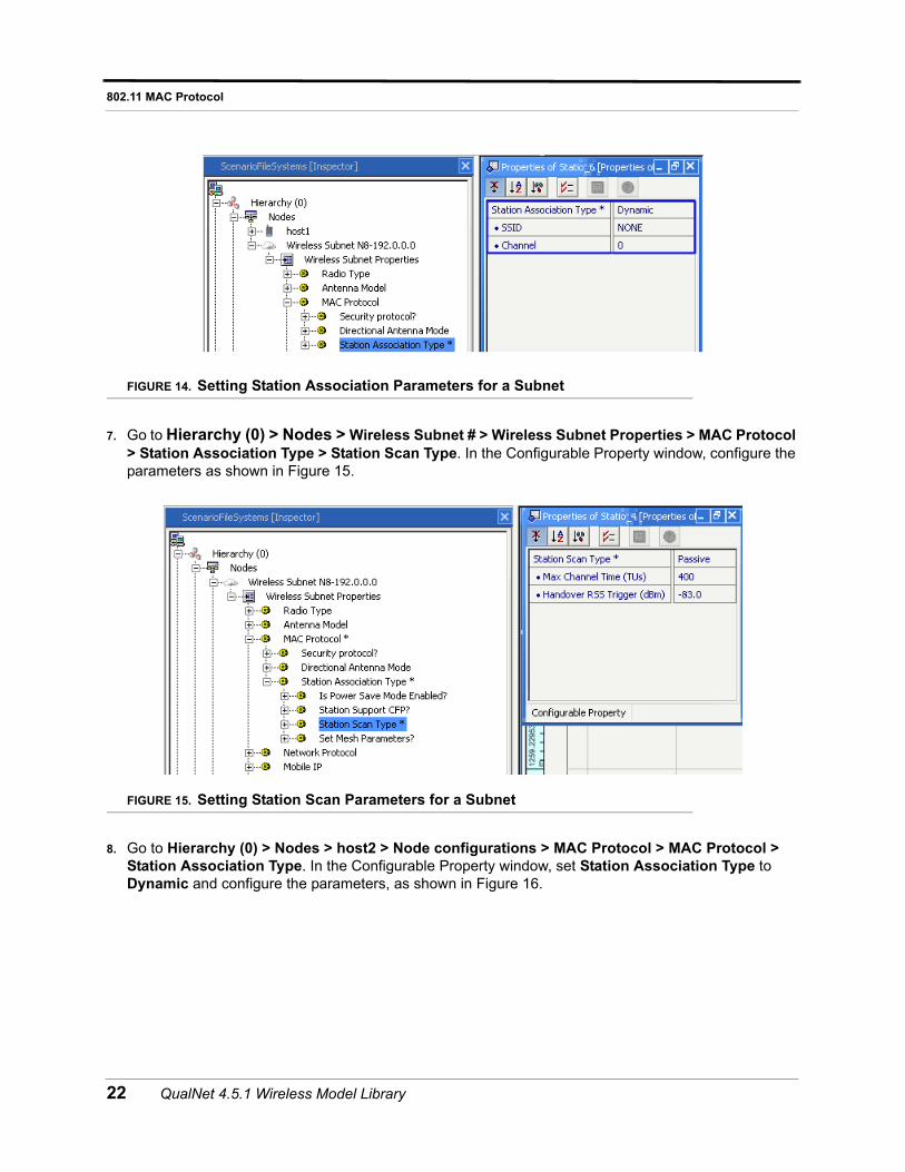
6. Go to Hierarchy (0) > Nodes > Wireless Subnet # > Wireless Subnet Properties > MAC Protocol > Station Association Type. In the Configurable Property window, set Station Association Type to Dynamic and set the parameters as shown Figure 14.
QualNet 4.5.1 Wireless Model Library 21
802.11 MAC Protocol
FIGURE 14. Setting Station Association Parameters for a Subnet
7. Go to Hierarchy (0) > Nodes > Wireless Subnet # > Wireless Subnet Properties > MAC Protocol > Station Association Type > Station Scan Type. In the Configurable Property window, configure the parameters as shown in Figure 15.
FIGURE 15. Setting Station Scan Parameters for a Subnet
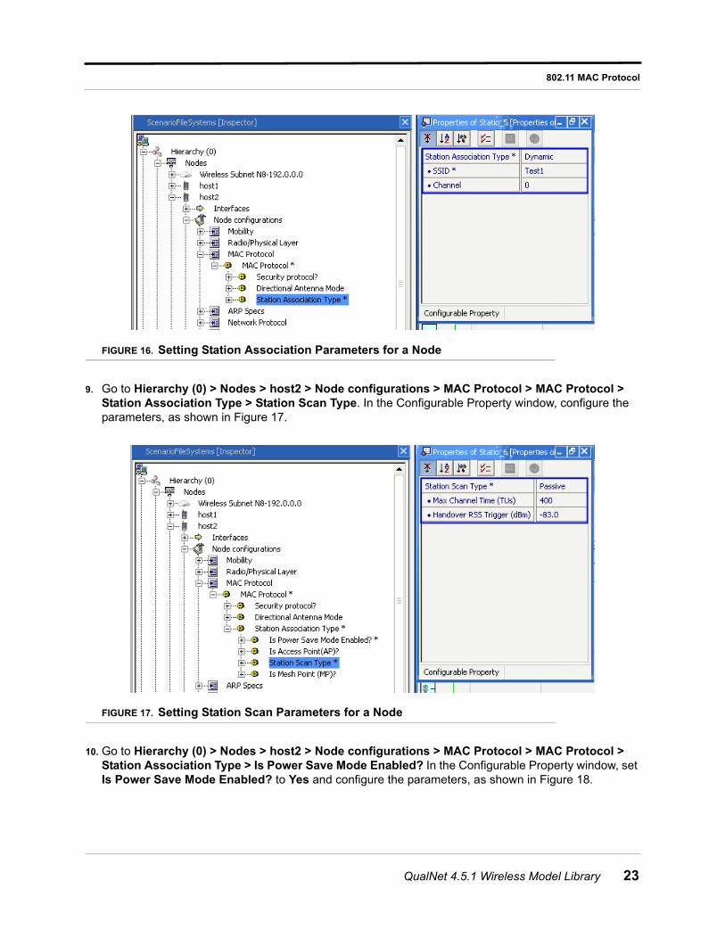
8. Go to Hierarchy (0) > Nodes > host2 > Node configurations > MAC Protocol > MAC Protocol > Station Association Type. In the Configurable Property window, set Station Association Type to Dynamic and configure the parameters, as shown in Figure 16.
22 QualNet 4.5.1 Wireless Model Library
802.11 MAC Protocol
FIGURE 16. Setting Station Association Parameters for a Node
9. Go to Hierarchy (0) > Nodes > host2 > Node configurations > MAC Protocol > MAC Protocol > Station Association Type > Station Scan Type. In the Configurable Property window, configure the parameters, as shown in Figure 17.
FIGURE 17. Setting Station Scan Parameters for a Node
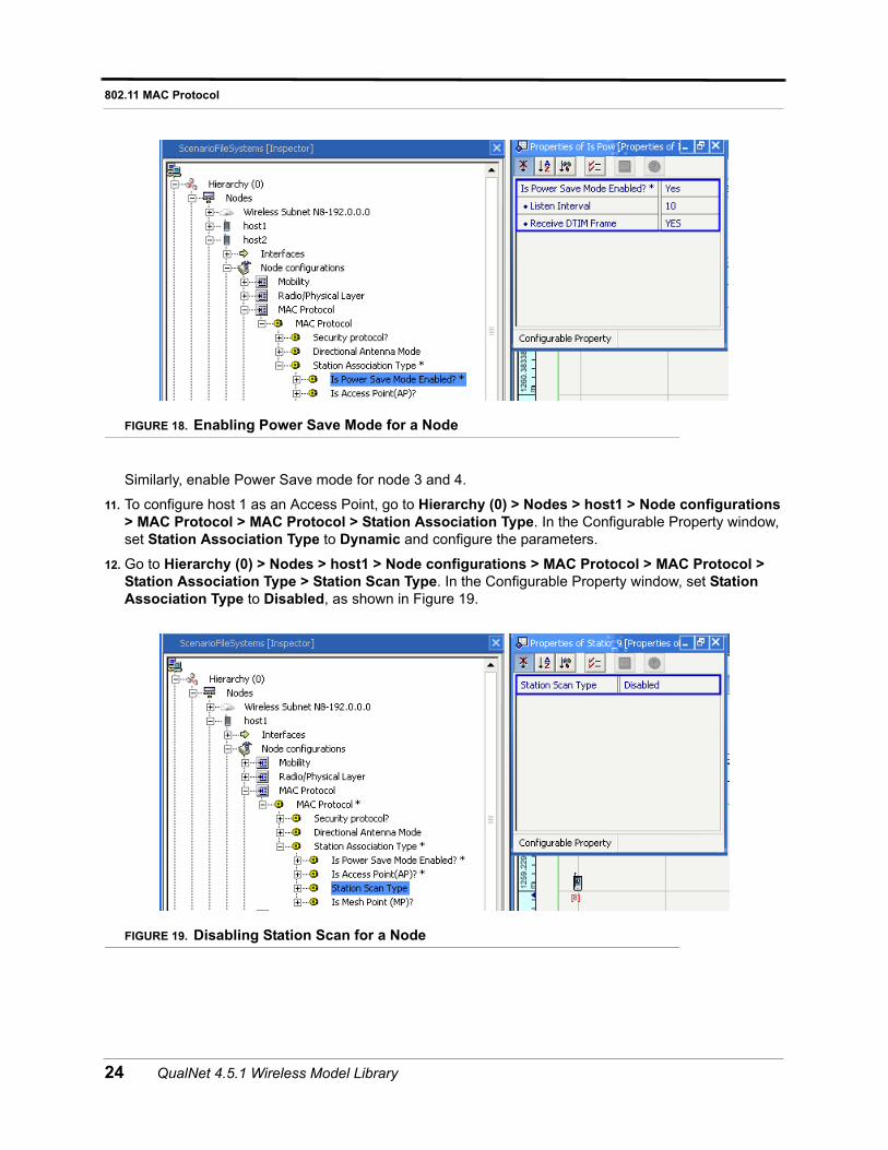
10. Go to Hierarchy (0) > Nodes > host2 > Node configurations > MAC Protocol > MAC Protocol > Station Association Type > Is Power Save Mode Enabled? In the Configurable Property window, set Is Power Save Mode Enabled? to Yes and configure the parameters, as shown in Figure 18.
QualNet 4.5.1 Wireless Model Library 23
802.11 MAC Protocol
FIGURE 18. Enabling Power Save Mode for a Node
Similarly, enable Power Save mode for node 3 and 4.
11. To configure host 1 as an Access Point, go to Hierarchy (0) > Nodes > host1 > Node configurations > MAC Protocol > MAC Protocol > Station Association Type. In the Configurable Property window, set Station Association Type to Dynamic and configure the parameters.
12. Go to Hierarchy (0) > Nodes > host1 > Node configurations > MAC Protocol > MAC Protocol > Station Association Type > Station Scan Type. In the Configurable Property window, set Station Association Type to Disabled, as shown in Figure 19.
FIGURE 19. Disabling Station Scan for a Node
24 QualNet 4.5.1 Wireless Model Library
802.11 MAC Protocol
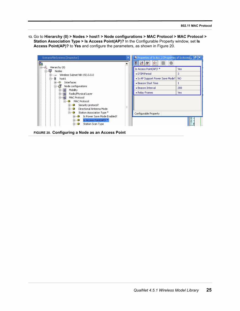
13. Go to Hierarchy (0) > Nodes > host1 > Node configurations > MAC Protocol > MAC Protocol > Station Association Type > Is Access Point(AP)? In the Configurable Property window, set Is Access Point(AP)? to Yes and configure the parameters, as shown in Figure 20.
FIGURE 20. Configuring a Node as an Access Point
QualNet 4.5.1 Wireless Model Library 25
802.11a/g PHY Model
802.11a/g PHY Model
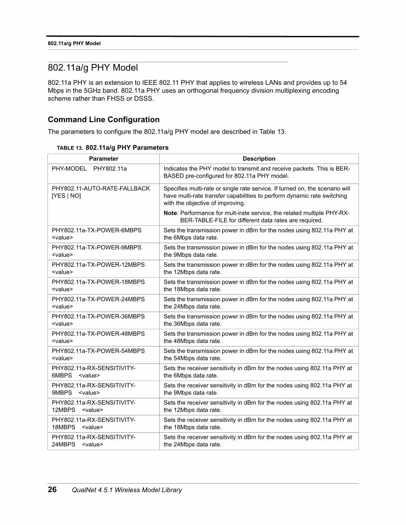
802.11a PHY is an extension to IEEE 802.11 PHY that applies to wireless LANs and provides up to 54 Mbps in the 5GHz band. 802.11a PHY uses an orthogonal frequency division multiplexing encoding scheme rather than FHSS or DSSS.
Command Line Configuration
The parameters to configure the 802.11a/g PHY model are described in Table 13.
TABLE 13. 802.11a/g PHY Parameters
Parameter Description
PHY-MODEL PHY802.11a Indicates the PHY model to transmit and receive packets. This is BER-BASED pre-configured for 802.11a PHY model.
PHY802.11-AUTO-RATE-FALLBACK[YES | NO]
Specifies multi-rate or single rate service. If turned on, the scenario will have multi-rate transfer capabilities to perform dynamic rate switching with the objective of improving.
Note: Performance for mult-irate service, the related multiple PHY-RX-BER-TABLE-FILE for different data rates are required.
PHY802.11a-TX-POWER-6MBPS <value>
Sets the transmission power in dBm for the nodes using 802.11a PHY at the 6Mbps data rate.
PHY802.11a-TX-POWER-9MBPS <value>
Sets the transmission power in dBm for the nodes using 802.11a PHY at the 9Mbps data rate.
PHY802.11a-TX-POWER-12MBPS <value>
Sets the transmission power in dBm for the nodes using 802.11a PHY at the 12Mbps data rate.
PHY802.11a-TX-POWER-18MBPS <value>
Sets the transmission power in dBm for the nodes using 802.11a PHY at the 18Mbps data rate.
PHY802.11a-TX-POWER-24MBPS <value>
Sets the transmission power in dBm for the nodes using 802.11a PHY at the 24Mbps data rate.
PHY802.11a-TX-POWER-36MBPS <value>
Sets the transmission power in dBm for the nodes using 802.11a PHY at the 36Mbps data rate.
PHY802.11a-TX-POWER-48MBPS <value>
Sets the transmission power in dBm for the nodes using 802.11a PHY at the 48Mbps data rate.
PHY802.11a-TX-POWER-54MBPS <value>
Sets the transmission power in dBm for the nodes using 802.11a PHY at the 54Mbps data rate.
PHY802.11a-RX-SENSITIVITY-6MBPS <value>
Sets the receiver sensitivity in dBm for the nodes using 802.11a PHY at the 6Mbps data rate.
PHY802.11a-RX-SENSITIVITY-9MBPS <value>
Sets the receiver sensitivity in dBm for the nodes using 802.11a PHY at the 9Mbps data rate.
PHY802.11a-RX-SENSITIVITY-12MBPS <value>
Sets the receiver sensitivity in dBm for the nodes using 802.11a PHY at the 12Mbps data rate.
PHY802.11a-RX-SENSITIVITY-18MBPS <value>
Sets the receiver sensitivity in dBm for the nodes using 802.11a PHY at the 18Mbps data rate.
PHY802.11a-RX-SENSITIVITY-24MBPS <value>
Sets the receiver sensitivity in dBm for the nodes using 802.11a PHY at the 24Mbps data rate.
26 QualNet 4.5.1 Wireless Model Library
802.11a/g PHY Model
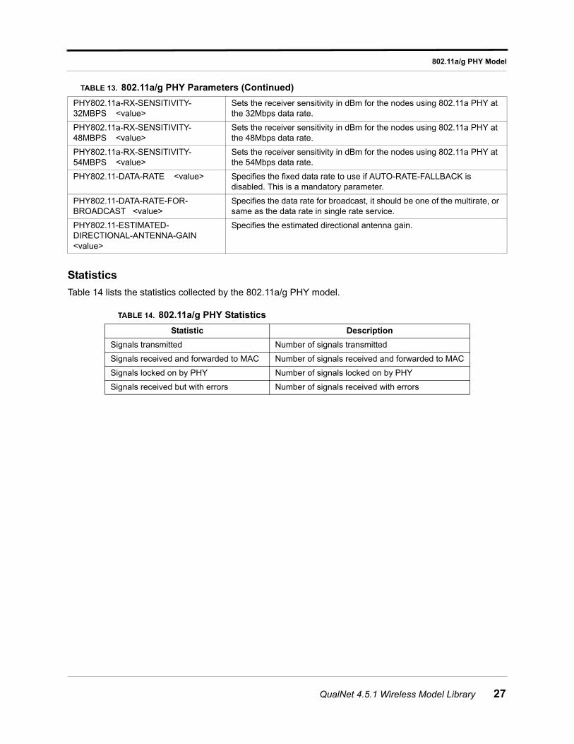
Statistics
Table 14 lists the statistics collected by the 802.11a/g PHY model.
PHY802.11a-RX-SENSITIVITY-32MBPS <value>
Sets the receiver sensitivity in dBm for the nodes using 802.11a PHY at the 32Mbps data rate.
PHY802.11a-RX-SENSITIVITY-48MBPS <value>
Sets the receiver sensitivity in dBm for the nodes using 802.11a PHY at the 48Mbps data rate.
PHY802.11a-RX-SENSITIVITY-54MBPS <value>
Sets the receiver sensitivity in dBm for the nodes using 802.11a PHY at the 54Mbps data rate.
PHY802.11-DATA-RATE <value> Specifies the fixed data rate to use if AUTO-RATE-FALLBACK is disabled. This is a mandatory parameter.
PHY802.11-DATA-RATE-FOR-BROADCAST <value>
Specifies the data rate for broadcast, it should be one of the multirate, or same as the data rate in single rate service.
PHY802.11-ESTIMATED-DIRECTIONAL-ANTENNA-GAIN <value>
Specifies the estimated directional antenna gain.
TABLE 14. 802.11a/g PHY Statistics
Statistic Description
Signals transmitted Number of signals transmitted
Signals received and forwarded to MAC Number of signals received and forwarded to MAC
Signals locked on by PHY Number of signals locked on by PHY
Signals received but with errors Number of signals received with errors
TABLE 13. 802.11a/g PHY Parameters (Continued)
QualNet 4.5.1 Wireless Model Library 27
802.11b PHY Model
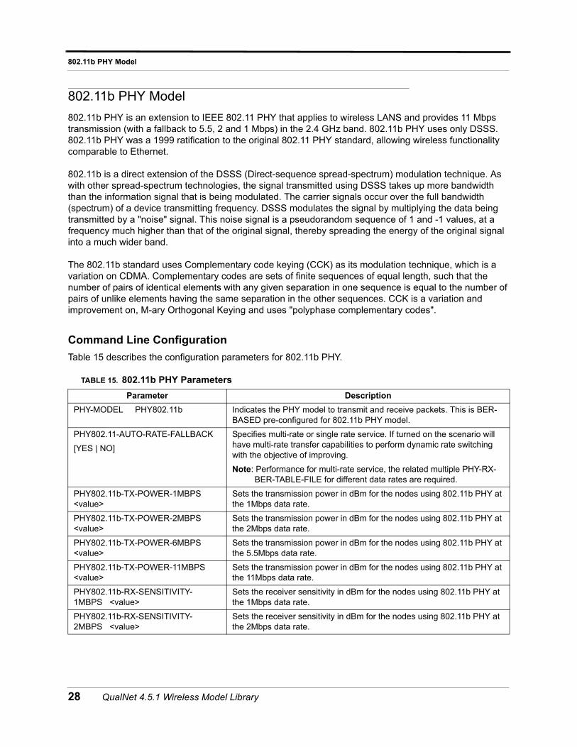
802.11b PHY Model
802.11b PHY is an extension to IEEE 802.11 PHY that applies to wireless LANS and provides 11 Mbps transmission (with a fallback to 5.5, 2 and 1 Mbps) in the 2.4 GHz band. 802.11b PHY uses only DSSS. 802.11b PHY was a 1999 ratification to the original 802.11 PHY standard, allowing wireless functionality comparable to Ethernet.
802.11b is a direct extension of the DSSS (Direct-sequence spread-spectrum) modulation technique. As with other spread-spectrum technologies, the signal transmitted using DSSS takes up more bandwidth than the information signal that is being modulated. The carrier signals occur over the full bandwidth (spectrum) of a device transmitting frequency. DSSS modulates the signal by multiplying the data being transmitted by a "noise" signal. This noise signal is a pseudorandom sequence of 1 and -1 values, at a frequency much higher than that of the original signal, thereby spreading the energy of the original signal into a much wider band.
The 802.11b standard uses Complementary code keying (CCK) as its modulation technique, which is a variation on CDMA. Complementary codes are sets of finite sequences of equal length, such that the number of pairs of identical elements with any given separation in one sequence is equal to the number of pairs of unlike elements having the same separation in the other sequences. CCK is a variation and improvement on, M-ary Orthogonal Keying and uses "polyphase complementary codes".
Command Line Configuration
Table 15 describes the configuration parameters for 802.11b PHY.
TABLE 15. 802.11b PHY Parameters
Parameter Description
PHY-MODEL PHY802.11b Indicates the PHY model to transmit and receive packets. This is BER-BASED pre-configured for 802.11b PHY model.
PHY802.11-AUTO-RATE-FALLBACK
[YES | NO]
Specifies multi-rate or single rate service. If turned on the scenario will have multi-rate transfer capabilities to perform dynamic rate switching with the objective of improving.
Note: Performance for multi-rate service, the related multiple PHY-RX-BER-TABLE-FILE for different data rates are required.
PHY802.11b-TX-POWER-1MBPS <value>
Sets the transmission power in dBm for the nodes using 802.11b PHY at the 1Mbps data rate.
PHY802.11b-TX-POWER-2MBPS <value>
Sets the transmission power in dBm for the nodes using 802.11b PHY at the 2Mbps data rate.
PHY802.11b-TX-POWER-6MBPS <value>
Sets the transmission power in dBm for the nodes using 802.11b PHY at the 5.5Mbps data rate.
PHY802.11b-TX-POWER-11MBPS <value>
Sets the transmission power in dBm for the nodes using 802.11b PHY at the 11Mbps data rate.
PHY802.11b-RX-SENSITIVITY-1MBPS <value>
Sets the receiver sensitivity in dBm for the nodes using 802.11b PHY at the 1Mbps data rate.
PHY802.11b-RX-SENSITIVITY-2MBPS <value>
Sets the receiver sensitivity in dBm for the nodes using 802.11b PHY at the 2Mbps data rate.
28 QualNet 4.5.1 Wireless Model Library
802.11b PHY Model
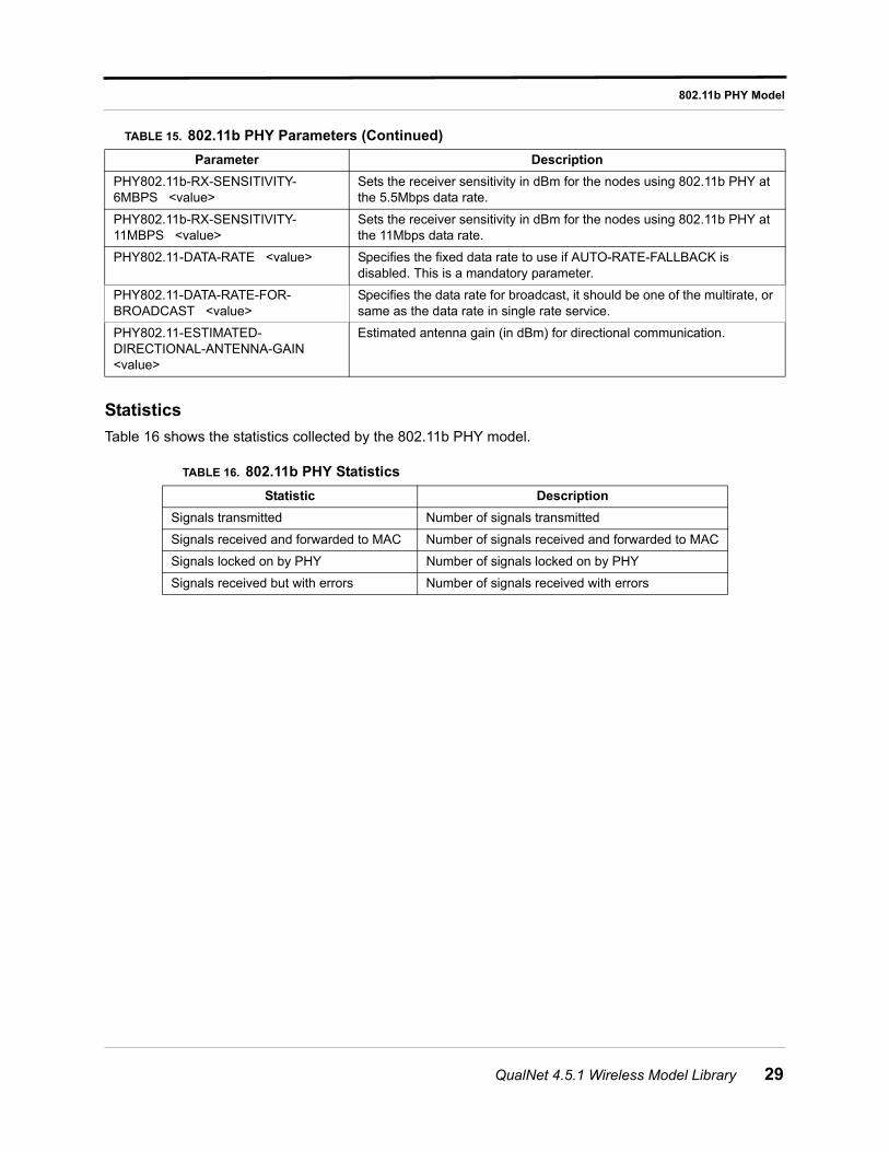
Statistics
Table 16 shows the statistics collected by the 802.11b PHY model.
PHY802.11b-RX-SENSITIVITY-6MBPS <value>
Sets the receiver sensitivity in dBm for the nodes using 802.11b PHY at the 5.5Mbps data rate.
PHY802.11b-RX-SENSITIVITY-11MBPS <value>
Sets the receiver sensitivity in dBm for the nodes using 802.11b PHY at the 11Mbps data rate.
PHY802.11-DATA-RATE <value> Specifies the fixed data rate to use if AUTO-RATE-FALLBACK is disabled. This is a mandatory parameter.
PHY802.11-DATA-RATE-FOR-BROADCAST <value>
Specifies the data rate for broadcast, it should be one of the multirate, or same as the data rate in single rate service.
PHY802.11-ESTIMATED-DIRECTIONAL-ANTENNA-GAIN <value>
Estimated antenna gain (in dBm) for directional communication.
TABLE 16. 802.11b PHY Statistics
Statistic Description
Signals transmitted Number of signals transmitted
Signals received and forwarded to MAC Number of signals received and forwarded to MAC
Signals locked on by PHY Number of signals locked on by PHY
Signals received but with errors Number of signals received with errors
TABLE 15. 802.11b PHY Parameters (Continued)
Parameter Description
QualNet 4.5.1 Wireless Model Library 29
802.11e MAC Protocol
802.11e MAC Protocol
The IEEE 802.11e MAC enhances the basic 802.11 MAC to provide quality-of-service support for audio and video streams. The 802.11e MAC defines a new Hybrid Coordination Function (HCF), which provides an Enhanced Distributed Channel Access (EDCA) method and an HCF Controlled Channel Access (HCCA) method.
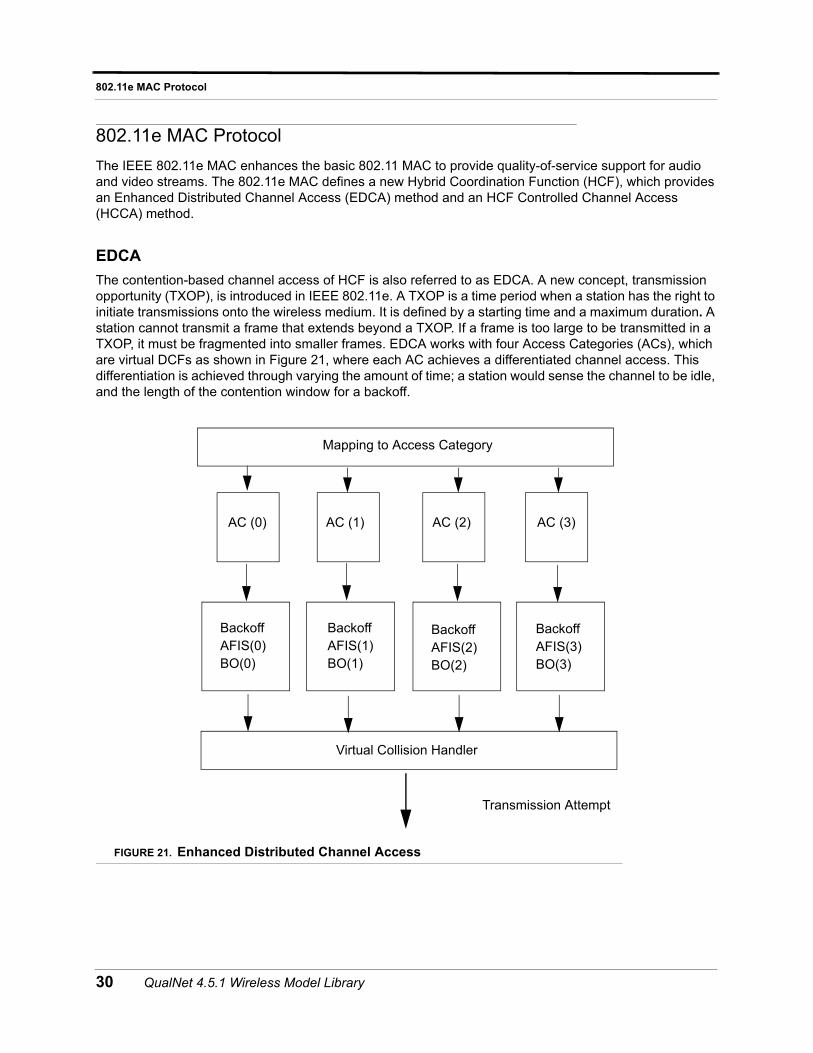
EDCA
The contention-based channel access of HCF is also referred to as EDCA. A new concept, transmission opportunity (TXOP), is introduced in IEEE 802.11e. A TXOP is a time period when a station has the right to initiate transmissions onto the wireless medium. It is defined by a starting time and a maximum duration. A station cannot transmit a frame that extends beyond a TXOP. If a frame is too large to be transmitted in a TXOP, it must be fragmented into smaller frames. EDCA works with four Access Categories (ACs), which are virtual DCFs as shown in Figure 21, where each AC achieves a differentiated channel access. This differentiation is achieved through varying the amount of time; a station would sense the channel to be idle, and the length of the contention window for a backoff.
FIGURE 21. Enhanced Distributed Channel Access
AC (0) AC (1) AC (2) AC (3)
Backoff AFIS(0) BO(0)
Backoff AFIS(1) BO(1)
Backoff AFIS(2) BO(2)
Backoff AFIS(3) BO(3)
Virtual Collision Handler
Mapping to Access Category
Transmission Attempt
30 QualNet 4.5.1 Wireless Model Library
802.11e MAC Protocol
Differentiated ACs are achieved by differentiating the Arbitration Inter-Frame Space (AIFS), the initial window size, and the maximum window size. That is, for AC i (where i is 0, 1, 2, or 3),the initial backoff window size is CWmin[i], the maximum backoff window size is CWmax[i], and the arbitration inter-frame space is AIFS[i]. For 0 < = i <= j <= 3, we have CWmin[i] >= CWmin[j] and CWmax[i] >= CWmax[j], and AIFS[i] >= AIFS[j] and at least one of above inequalities must be “not equal to”. In other words, the EDCA employs AIFS[i] , CWmin[i] , and CWmax[i] (all for i=0,...,3) instead of DIFS, min CW, and max CW, respectively. If one AC has a smaller AIFS or min CW, the traffic of AC has a better chance to access the wireless medium earlier, thus providing the QoS effect.
HCCA
The contention-free channel access of HCF is also referred to as HCCA. HCCA allows for the reservation of TXOPs with the HC. A non-AP QSTA based on its requirements requests the HC for TXOPs - both for its own transmissions as well as transmissions from the QAP to itself. The request is initiated by the Station Management Entity (SME) of the non-AP QSTA. The HC, which is collocated at the QAP, either accepts or rejects the request based on an admission control policy. If the request is accepted, the HC schedules TXOPs for both the QAP and the non-AP QSTA.
For transmissions from the non-AP QSTA, the HC polls the non-AP QSTA based on the parameters supplied by the non-AP QSTA at the time of its request. For transmissions to the non-AP QSTA, the QAP directly obtains TXOPs from the collocated HC and delivers the queued frames to the non-AP QSTA, again based on the parameters supplied by the non-AP QSTA. This mechanism may be used for applications such as voice and video, which may need periodic service from the HC.
Admission Control and Scheduling of HCCAIn QualNet 802.11e MAC model traffic specification includes user priority that will generate four traffic streams as per TSID (TS Identification). The QSTA initiates ADDTS request only if the priority of the data is between 4 to 7. The TSID will be generated by adding eight to User priority. HC will always accept the ADDTS request. HC will poll QSTA based on the priority of the traffic stream.
Command Line Configuration
To specify 802.11e MAC as the MAC protocol, include the following parameter in the scenario configuration (.config) file:
MAC-PROTOCOL MAC-DOT11e
Note: The QualNet 802.11e MAC model is based on the 802.11 MAC model. In order to use 802.11e MAC in a scenario, you will also need to configure some 802.11 MAC parameters. See the 802.11 MAC section of this model library for details of the 802.11 MAC model.
Table 17 shows 802.11 MAC configuration parameters.
Note: Unless otherwise specified, the parameters in Table 17 can be specified at the global, node, subnet and interface levels.
QualNet 4.5.1 Wireless Model Library 31
802.11e MAC Protocol
GUI Configuration
In the GUI, you can enable 802.11e MAC for a wireless subnet, a node, an interface of a node, or globally for all the nodes. The following steps describe how to configure 802.11e MAC for a subnet.
Note: The QualNet 802.11e MAC model is based on the 802.11 MAC model. In order to use 802.11e MAC in a scenario, you will also need to configure some 802.11 MAC parameters. See the 802.11 MAC section of this model library for details of the 802.11 MAC model.
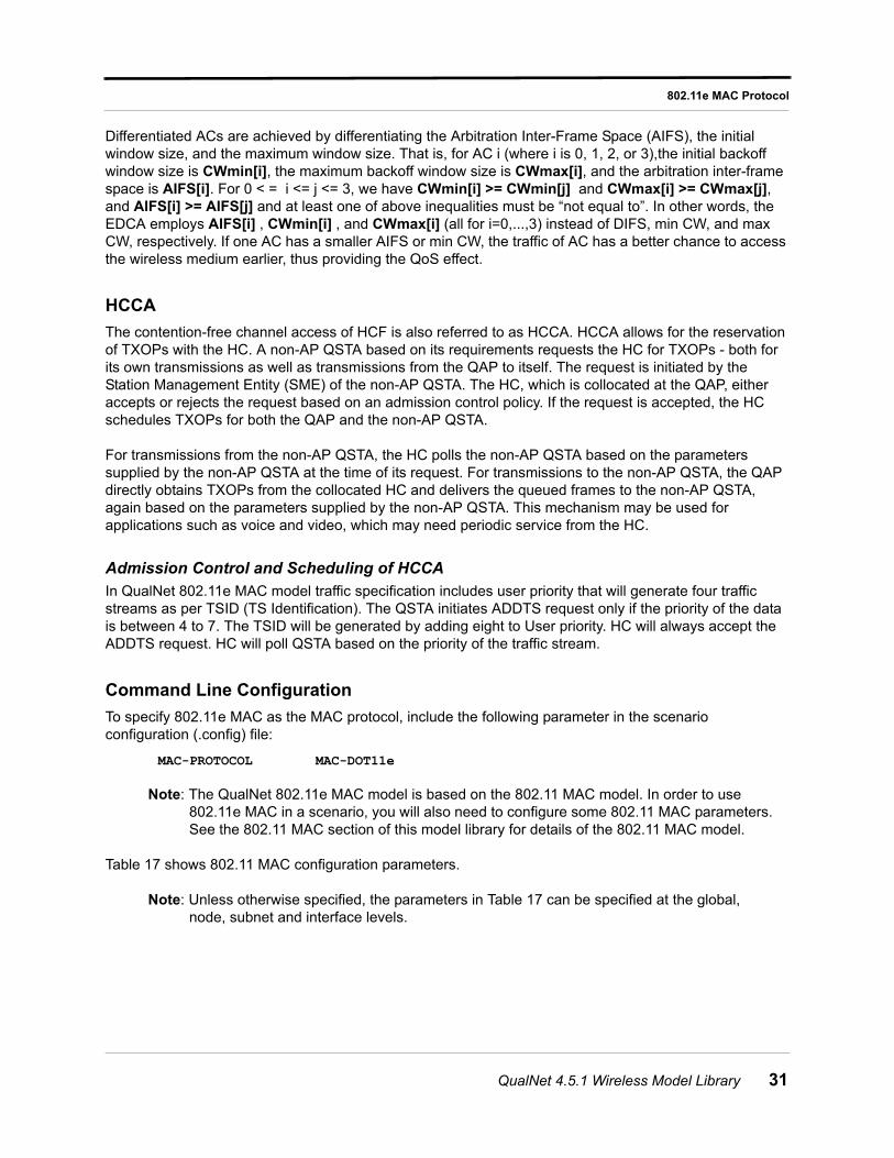
1. Go to Hierarchy # > Nodes > Wireless Subnet # > Wireless Subnet Properties > MAC Protocol. In the Configurable Property window, set MAC Protocol to 802.11e and set the protocol properties, as shown in Figure 22.
Note: To use only EDCA, set Enable HCCA to No.
TABLE 17. 802.11e Parameters
Parameter Description
MAC-DOT11e-ASSOCIATION
[DYNAMIC | NONE]
This parameter configures the mode of association with QAP/AP.
Currently it supports two modes; DYNAMIC mode specifies that QSTA needs to be dynamically associated will QAP. This will set up a QIBSS (QoS enabled Infrastructure mode).
If this parameter is NONE then QSTA will work in Ad-Hoc mode. This will help to set up an ad hoc mode QoS enabled scenario.
MAC-DOT11e-HCCA [YES | NO] This parameter enables HCCA at a node/interface.
The default value is NO, in this case only EDCA will be used.
MAC-DOT11e-AP [YES | NO] This parameter configures a node/interface as AP.
The default value is NO.
MAC-DOT11e-HC [YES | NO] This parameter configures a node/interface as HC. This parameter is only valid for an AP.
Note: This parameter can be specified only at the node and interface levels.
The default value is NO.
MAC-DOT11e-CAP-LIMIT <value> This parameter specifies the maximum duration of CAP.
HC cannot start CAP for more then this duration in a beacon period. This parameter is specified in Time unites (TUs).
Note: This parameter can be specified only at the node and interface levels.
The default value for CAP-LIMT is 50 TU where TU is 1024 micro-seconds.
32 QualNet 4.5.1 Wireless Model Library
802.11e MAC Protocol
FIGURE 22. Configuring 802.11e for a Subnet
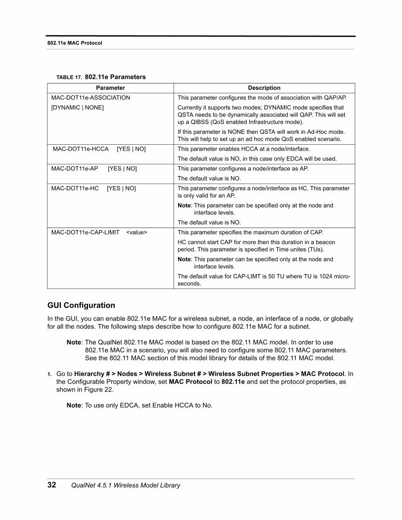
2. Go to Hierarchy # > Nodes > Wireless Subnet # > Wireless Subnet Properties > MAC Protocol > Station Association Type. In the Configurable Property window, set Station Association Type to Dynamic and configure the parameters, as shown in Figure 23.
FIGURE 23. Configuring Association Type
3. Go to Hierarchy # > Nodes > host# > Node configurations > MAC Protocol > MAC Protocol > Station Association Type > Is Access Point(AP)? In the configurable property window, set Is Access Point(AP) to Yes and configure the parameters, as shown in Figure 24.
QualNet 4.5.1 Wireless Model Library 33
802.11e MAC Protocol
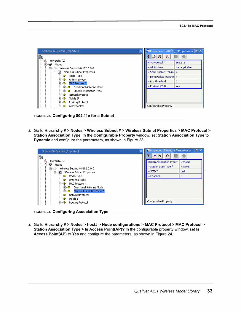
FIGURE 24. Configuring Access Point
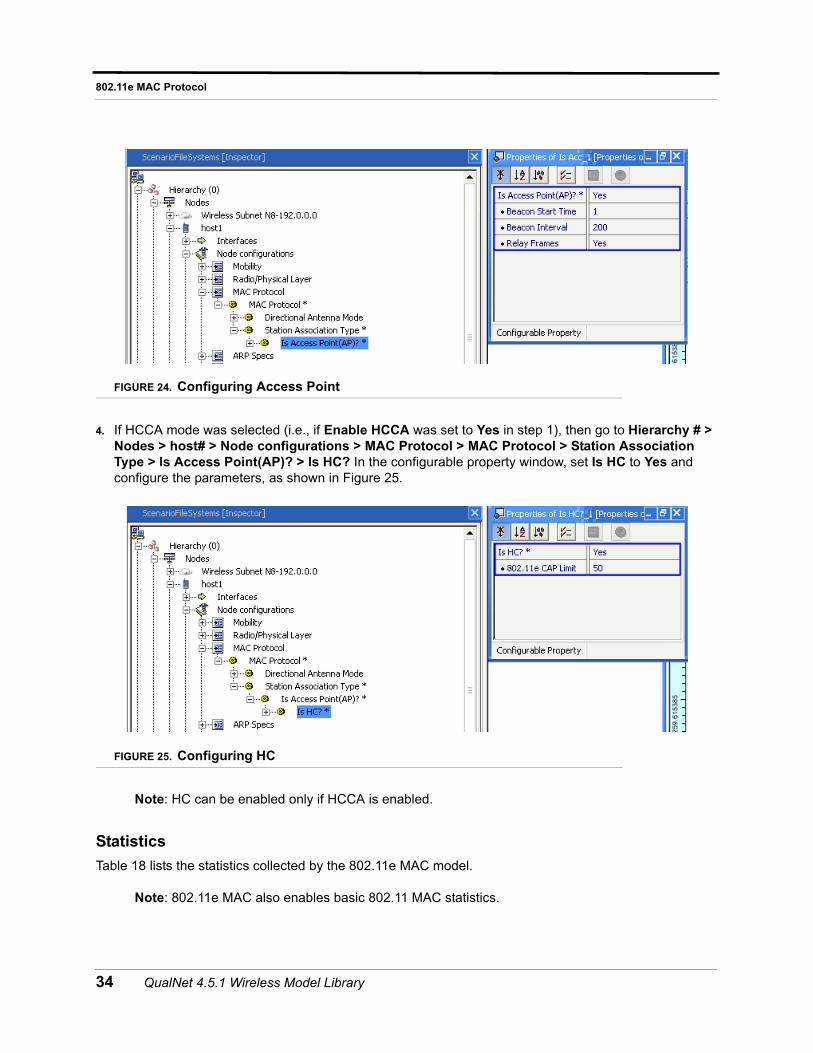
4. If HCCA mode was selected (i.e., if Enable HCCA was set to Yes in step 1), then go to Hierarchy # > Nodes > host# > Node configurations > MAC Protocol > MAC Protocol > Station Association Type > Is Access Point(AP)? > Is HC? In the configurable property window, set Is HC to Yes and configure the parameters, as shown in Figure 25.
FIGURE 25. Configuring HC
Note: HC can be enabled only if HCCA is enabled.
Statistics
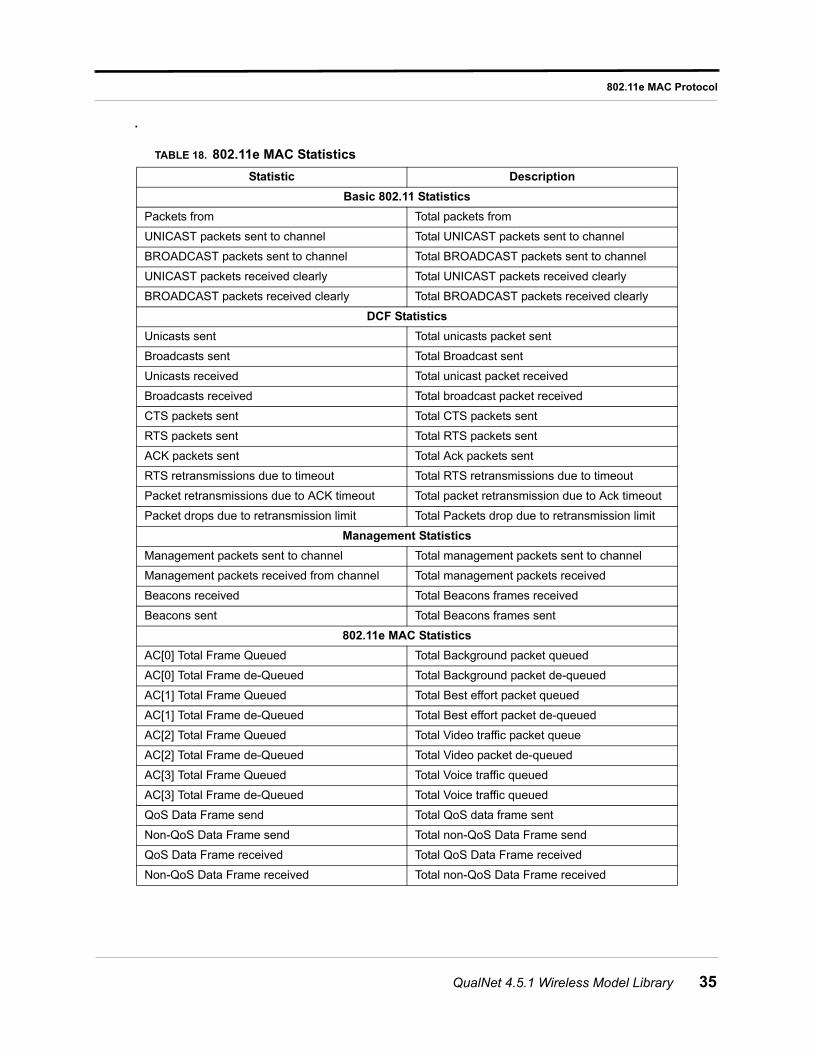
Table 18 lists the statistics collected by the 802.11e MAC model.
Note: 802.11e MAC also enables basic 802.11 MAC statistics.
34 QualNet 4.5.1 Wireless Model Library
802.11e MAC Protocol
.
TABLE 18. 802.11e MAC Statistics
Statistic Description
Basic 802.11 Statistics
Packets from Total packets from
UNICAST packets sent to channel Total UNICAST packets sent to channel
BROADCAST packets sent to channel Total BROADCAST packets sent to channel
UNICAST packets received clearly Total UNICAST packets received clearly
BROADCAST packets received clearly Total BROADCAST packets received clearly
DCF Statistics
Unicasts sent Total unicasts packet sent
Broadcasts sent Total Broadcast sent
Unicasts received Total unicast packet received
Broadcasts received Total broadcast packet received
CTS packets sent Total CTS packets sent
RTS packets sent Total RTS packets sent
ACK packets sent Total Ack packets sent
RTS retransmissions due to timeout Total RTS retransmissions due to timeout
Packet retransmissions due to ACK timeout Total packet retransmission due to Ack timeout
Packet drops due to retransmission limit Total Packets drop due to retransmission limit
Management Statistics
Management packets sent to channel Total management packets sent to channel
Management packets received from channel Total management packets received
Beacons received Total Beacons frames received
Beacons sent Total Beacons frames sent
802.11e MAC Statistics
AC[0] Total Frame Queued Total Background packet queued
AC[0] Total Frame de-Queued Total Background packet de-queued
AC[1] Total Frame Queued Total Best effort packet queued
AC[1] Total Frame de-Queued Total Best effort packet de-queued
AC[2] Total Frame Queued Total Video traffic packet queue
AC[2] Total Frame de-Queued Total Video packet de-queued
AC[3] Total Frame Queued Total Voice traffic queued
AC[3] Total Frame de-Queued Total Voice traffic queued
QoS Data Frame send Total QoS data frame sent
Non-QoS Data Frame send Total non-QoS Data Frame send
QoS Data Frame received Total QoS Data Frame received
Non-QoS Data Frame received Total non-QoS Data Frame received
QualNet 4.5.1 Wireless Model Library 35
802.11e MAC Protocol
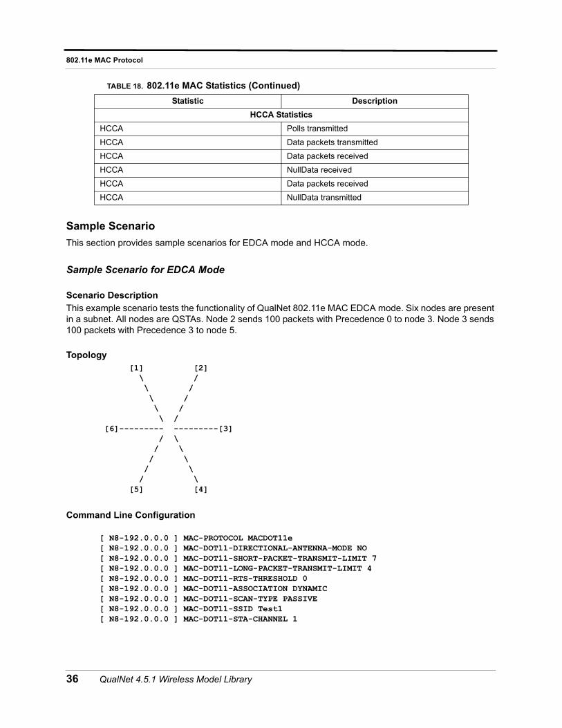
Sample Scenario
This section provides sample scenarios for EDCA mode and HCCA mode.
Sample Scenario for EDCA Mode
Scenario Description
This example scenario tests the functionality of QualNet 802.11e MAC EDCA mode. Six nodes are present in a subnet. All nodes are QSTAs. Node 2 sends 100 packets with Precedence 0 to node 3. Node 3 sends 100 packets with Precedence 3 to node 5.
Topology [1] [2] \ / \ / \ / \ / \ / [6]--------- ---------[3] / \ / \ / \ / \ / \ [5] [4]
Command Line Configuration
[ N8-192.0.0.0 ] MAC-PROTOCOL MACDOT11e[ N8-192.0.0.0 ] MAC-DOT11-DIRECTIONAL-ANTENNA-MODE NO[ N8-192.0.0.0 ] MAC-DOT11-SHORT-PACKET-TRANSMIT-LIMIT 7[ N8-192.0.0.0 ] MAC-DOT11-LONG-PACKET-TRANSMIT-LIMIT 4[ N8-192.0.0.0 ] MAC-DOT11-RTS-THRESHOLD 0[ N8-192.0.0.0 ] MAC-DOT11-ASSOCIATION DYNAMIC[ N8-192.0.0.0 ] MAC-DOT11-SCAN-TYPE PASSIVE[ N8-192.0.0.0 ] MAC-DOT11-SSID Test1[ N8-192.0.0.0 ] MAC-DOT11-STA-CHANNEL 1
HCCA Statistics
HCCA Polls transmitted
HCCA Data packets transmitted
HCCA Data packets received
HCCA NullData received
HCCA Data packets received
HCCA NullData transmitted
TABLE 18. 802.11e MAC Statistics (Continued)
Statistic Description
36 QualNet 4.5.1 Wireless Model Library
802.11e MAC Protocol
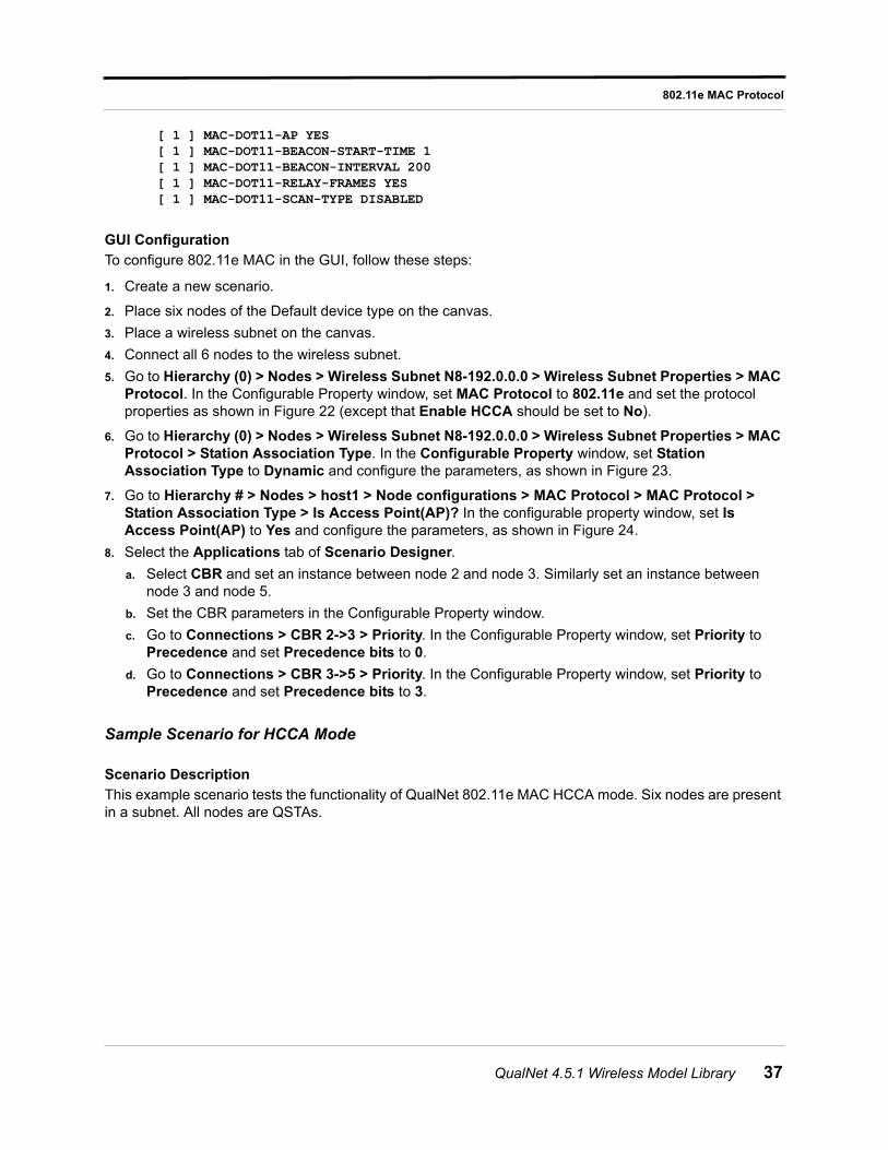
[ 1 ] MAC-DOT11-AP YES[ 1 ] MAC-DOT11-BEACON-START-TIME 1[ 1 ] MAC-DOT11-BEACON-INTERVAL 200[ 1 ] MAC-DOT11-RELAY-FRAMES YES[ 1 ] MAC-DOT11-SCAN-TYPE DISABLED
GUI Configuration
To configure 802.11e MAC in the GUI, follow these steps:
1. Create a new scenario.
2. Place six nodes of the Default device type on the canvas.
3. Place a wireless subnet on the canvas.
4. Connect all 6 nodes to the wireless subnet.
5. Go to Hierarchy (0) > Nodes > Wireless Subnet N8-192.0.0.0 > Wireless Subnet Properties > MAC Protocol. In the Configurable Property window, set MAC Protocol to 802.11e and set the protocol properties as shown in Figure 22 (except that Enable HCCA should be set to No).
6. Go to Hierarchy (0) > Nodes > Wireless Subnet N8-192.0.0.0 > Wireless Subnet Properties > MAC Protocol > Station Association Type. In the Configurable Property window, set Station Association Type to Dynamic and configure the parameters, as shown in Figure 23.
7. Go to Hierarchy # > Nodes > host1 > Node configurations > MAC Protocol > MAC Protocol > Station Association Type > Is Access Point(AP)? In the configurable property window, set Is Access Point(AP) to Yes and configure the parameters, as shown in Figure 24.
8. Select the Applications tab of Scenario Designer.
a. Select CBR and set an instance between node 2 and node 3. Similarly set an instance between node 3 and node 5.
b. Set the CBR parameters in the Configurable Property window.
c. Go to Connections > CBR 2->3 > Priority. In the Configurable Property window, set Priority to Precedence and set Precedence bits to 0.
d. Go to Connections > CBR 3->5 > Priority. In the Configurable Property window, set Priority to Precedence and set Precedence bits to 3.
Sample Scenario for HCCA Mode
Scenario Description
This example scenario tests the functionality of QualNet 802.11e MAC HCCA mode. Six nodes are present in a subnet. All nodes are QSTAs.
QualNet 4.5.1 Wireless Model Library 37
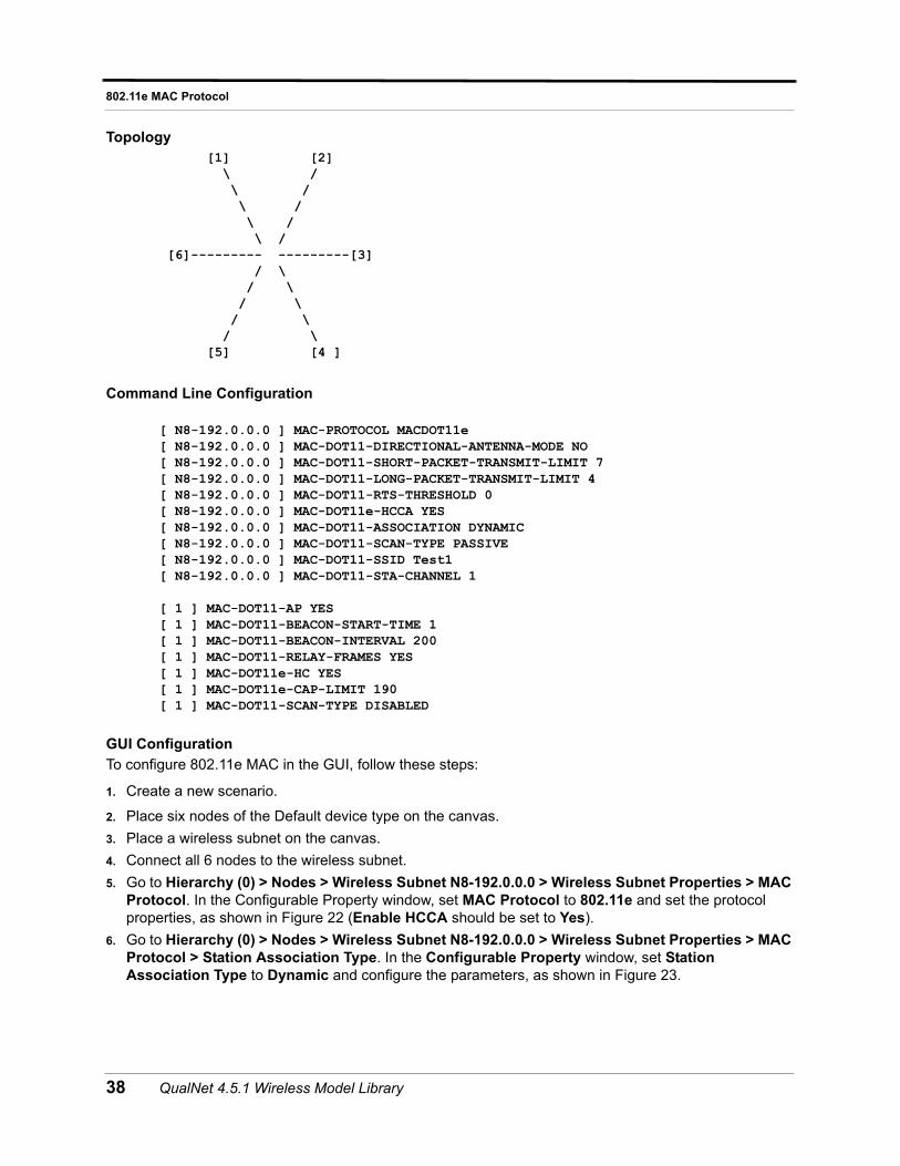
802.11e MAC Protocol
Topology [1] [2] \ / \ / \ / \ / \ / [6]--------- ---------[3] / \ / \ / \ / \ / \ [5] [4 ]
Command Line Configuration
[ N8-192.0.0.0 ] MAC-PROTOCOL MACDOT11e[ N8-192.0.0.0 ] MAC-DOT11-DIRECTIONAL-ANTENNA-MODE NO[ N8-192.0.0.0 ] MAC-DOT11-SHORT-PACKET-TRANSMIT-LIMIT 7[ N8-192.0.0.0 ] MAC-DOT11-LONG-PACKET-TRANSMIT-LIMIT 4[ N8-192.0.0.0 ] MAC-DOT11-RTS-THRESHOLD 0[ N8-192.0.0.0 ] MAC-DOT11e-HCCA YES[ N8-192.0.0.0 ] MAC-DOT11-ASSOCIATION DYNAMIC[ N8-192.0.0.0 ] MAC-DOT11-SCAN-TYPE PASSIVE[ N8-192.0.0.0 ] MAC-DOT11-SSID Test1[ N8-192.0.0.0 ] MAC-DOT11-STA-CHANNEL 1
[ 1 ] MAC-DOT11-AP YES[ 1 ] MAC-DOT11-BEACON-START-TIME 1[ 1 ] MAC-DOT11-BEACON-INTERVAL 200[ 1 ] MAC-DOT11-RELAY-FRAMES YES[ 1 ] MAC-DOT11e-HC YES[ 1 ] MAC-DOT11e-CAP-LIMIT 190[ 1 ] MAC-DOT11-SCAN-TYPE DISABLED
GUI Configuration
To configure 802.11e MAC in the GUI, follow these steps:
1. Create a new scenario.
2. Place six nodes of the Default device type on the canvas.
3. Place a wireless subnet on the canvas.
4. Connect all 6 nodes to the wireless subnet.
5. Go to Hierarchy (0) > Nodes > Wireless Subnet N8-192.0.0.0 > Wireless Subnet Properties > MAC Protocol. In the Configurable Property window, set MAC Protocol to 802.11e and set the protocol properties, as shown in Figure 22 (Enable HCCA should be set to Yes).
6. Go to Hierarchy (0) > Nodes > Wireless Subnet N8-192.0.0.0 > Wireless Subnet Properties > MAC Protocol > Station Association Type. In the Configurable Property window, set Station Association Type to Dynamic and configure the parameters, as shown in Figure 23.
38 QualNet 4.5.1 Wireless Model Library
802.11e MAC Protocol
7. Go to Hierarchy # > Nodes > host1 > Node configurations > MAC Protocol > MAC Protocol > Station Association Type > Is Access Point(AP)? In the configurable property window, set Is Access Point(AP) to Yes and configure the parameters, as shown in Figure 24.
8. Go to Hierarchy (0) > Nodes > host1 > Node configurations > MAC Protocol > MAC Protocol > Station Association Type > Is Access Point(AP)? > Is HC? In the configurable property window, set Is HC to Yes and configure the parameters, as shown in Figure 25.
9. Select the Applications tab of Scenario Designer.
a. Select CBR and set an instance between node 2 and node 3. Similarly set an instance between node 3 and node 5.
b. Set the CBR parameters in the Configurable Property window.
c. Go to Connections > CBR 2->3 > Priority. In the Configurable Property window, set Priority to Precedence and set Precedence bits to 0.
d. Go to Connections > CBR 3->5 > Priority. In the Configurable Property window, set Priority to Precedence and set Precedence bits to 3.
QualNet 4.5.1 Wireless Model Library 39
802.11s MAC Protocol
802.11s MAC Protocol
802.11s aims to standardize wireless connectivity for multiple hops within the 802.11 framework. End-to-end connectivity across a wireless medium requires that each device connect to one or more neighbors so that a mesh can form. The resulting mesh permits selection of one of the multiple paths for end-point delivery.
IBSS, or ad-hoc networks, use layer 3 route selection and offer a single IP hop between peers. In comparison, Mesh networks use a layer 2 mechanism to determine optimal paths within the mesh and permit multiple MAC layer hops between a single IP hop.
Access points, that form infrastructure or BSS networks, typically interconnect to each other via a wired infrastructure such as an 802.1 switched LAN. For traffic between BSS networks, mesh services enables secure wireless inter-operability.
While 802.11 has evolved to higher radio speeds, and resulting shorter range, the overall deployment and coverage distance remains the same. Mesh services offer a multiple hop solution across such distances that does not increase the need for cabling and reduces deployment time.
Mesh services extend existing 802.11 services. A mesh enabled station is termed a Mesh Point. A mesh point or MP may also offer AP or portal services. Mesh points are envisaged to be dedicated devices, such as APs, that manage BSS stations or forward traffic, or end-user equipment such as digital TVs, cameras or printers.
The 802.11s draft specifies formation of mesh networks that provide self-configuring neighbor discovery, peer association, path discovery and forwarding. It also addresses inter-connectivity with other non-802.11 and IP networks.
Implemented Features
A list of 802.11s features implemented in QualNet 4.5 follows:
• 802.11 stations provide mesh services. These are termed Mesh Points (MPs).
• They may independently offer Access Point services (MAPs).
• At inter-networking points, they may offer Portal functionality (MPPs).
• Cover mesh management and operations.
• Cover path protocol and path metric interfaces.
Mesh Management
Managing Mesh properties consists of the following sections:
• MP Initialization
• MPs provide a 5 stage initialization process.
• Attempt to adjust beacon offset to minimize collision.
• Block upper layer traffic during this phase.
• Stations cannot associate with MAPs during this phase.
• Neighbor Discovery
• Passive mode neighbor discovery by listening to beacons.
40 QualNet 4.5.1 Wireless Model Library
802.11s MAC Protocol
• Beacon frames use mesh information elements to advertise capabilities.
• Mesh profiles within beacons identify candidate mesh neighbors.
• Peer Link Establishment
• Mesh peers use 4-way handshake.
• Exchange Open and Confirm association frames.
• Link establishment is rate limited.
• Link State Measure and Exchange
• Link quality is measured using path metric.
• The super-ordinate MP communicates link quality to peer.
• Link state measures used for optimal radio-aware path selection
• Peer Link Maintenance
• Periodic link state exchanges update link quality measures.
• Unsuccessful link state exchanges determine termination of link.
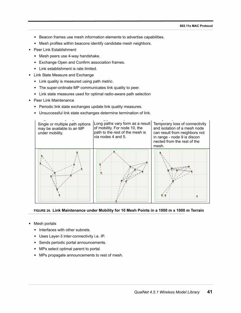
FIGURE 26. Link Maintenance under Mobility for 10 Mesh Points in a 1000 m x 1000 m Terrain
• Mesh portals
• Interfaces with other subnets.
• Uses Layer-3 inter-connectivity i.e. IP.
• Sends periodic portal announcements.
• MPs select optimal parent to portal.
• MPs propagate announcements to rest of mesh.
Single or multiple path optionsmay be available to an MPunder mobility.
Long paths vary form as a resultof mobility. For node 10, thepath to the rest of the mesh isvia nodes 4 and 5.
Temporary loss of connectivityand isolation of a mesh nodecan result from neighbors notin range - node 9 is disconnected from the rest of themesh.
QualNet 4.5.1 Wireless Model Library 41
802.11s MAC Protocol
HWMP (Hybrid Wireless Mesh Protocol)
HWMP is the default path protocol for 802.11s. It uses AODV primitives and has been extended to use radio-aware metrics, not hop count. It has also been extended for proactive tree formation.
• Default path protocol for 802.11s
• Uses AODV primitives
• Extended to use radio metrics, not hop count.
• Extended for proactive tree formation.
• Triggered Route Requests
• RREQ broadcasts used for on-demand route discovery.
• Relay subject to TTL/hop count limits, and other flags.
• Configurable for expanding-ring or full TTL mechanism.
• MPs proxy for associated stations.
• Route replies
• Configurable for reply destination or intermediate.
• Best path at each hop uses link state measures.
• Destination proxies for associated stations.
• Route errors
• Maintain routes on link failure or termination.
• Notifies precursors with active routes.
• May be broadcast or unicast.
• Root and root announcements
• Enables proactive spanning tree formation.
• Single configurable root per mesh.
• Periodic root announcement indicate active root.
• MPs select best parent towards root.
• MPs relay announcements to rest of mesh.
• MPs may register with root for bi-directional tree.
• MPs use legacy mechanism for proxy registration.
• Spanning tree changes dynamically.
42 QualNet 4.5.1 Wireless Model Library
802.11s MAC Protocol
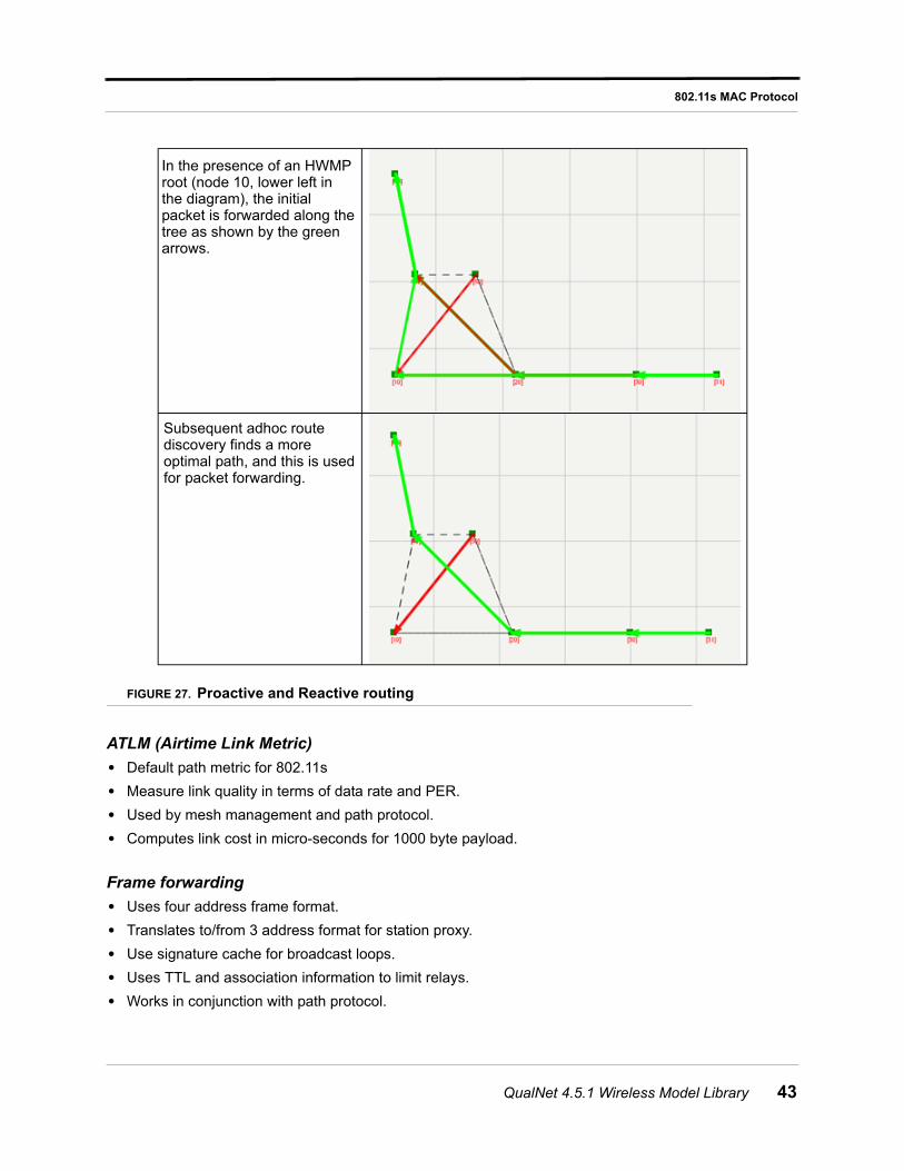
FIGURE 27. Proactive and Reactive routing
ATLM (Airtime Link Metric)
• Default path metric for 802.11s
• Measure link quality in terms of data rate and PER.
• Used by mesh management and path protocol.
• Computes link cost in micro-seconds for 1000 byte payload.
Frame forwarding
• Uses four address frame format.
• Translates to/from 3 address format for station proxy.
• Use signature cache for broadcast loops.
• Uses TTL and association information to limit relays.
• Works in conjunction with path protocol.
In the presence of an HWMProot (node 10, lower left inthe diagram), the initialpacket is forwarded along thetree as shown by the greenarrows.
Subsequent adhoc routediscovery finds a moreoptimal path, and this is usedfor packet forwarding.
QualNet 4.5.1 Wireless Model Library 43
802.11s MAC Protocol
Omitted Features
Features not implemented in this development are:
• Channel convergence.
• Authentication between MPs.
• Layer 2 inter-connectivity with other IEEE LANs.
• AODV's blacklist and local repair capability.
• HWMP route maintenance.
• NULL metric and path protocol.
• Use of 6-address format for frame forwarding.
• End to end ordering
• Non-forwarding or light-weight MPs
• Support for QoS, congestion control or MDA.
• Power save mode.
Command Line Configuration
Mesh Point Configuration
Table 19 provides a list of the configuration parameters that relate to Mesh Point configuration:
TABLE 19. Mesh Point Configuration
Parameter Description
MAC-DOT11s-MESH-POINT YES | NO Configures nodes or interfaces for mesh services as per 802.11s. Mesh-enabled nodes, or Mesh Points (MPs), self-configure for neighbor discovery, peer link setup, and path selection.
Generally, this is the only parameter that needs to be set for mesh nodes. All other parameters are optional and ignored for non-mesh points.
Mesh services can be configured for a station or an AP. The implementation does not support QoS and reports an error if mesh services are enabled for HC. Also, mesh enabled nodes do not support power-save features.
The default is NO.
MAC-DOT11s-MESH-ID <mesh-ID> Configures mesh identifiers. MPs with a common mesh identifier can associate to form a mesh network.
The default is Mesh1. Maximum length is 32 characters.
MAC-DOT11s-PATH-PROTOCOL HWMP Configures the path protocol to use for route discovery and path selection. HWMP is the only option currently available.
The default is HWMP.
MAC-DOT11s-PATH-METRIC AIRTIME Configures the path metric to use for path costs. AIRTIME link metric is the only option currently available.
The default is AIRTIME.
44 QualNet 4.5.1 Wireless Model Library
802.11s MAC Protocol
MAC-DOT11s-LINK-SETUP-PERIOD <value>
Configures the period for neighbor link establishment. An MP attempts to create a link with newly discovered neighbors at periodic intervals.
The default is 1 second.
MAC-DOT11s-LINK-SETUP-RATE-LIMIT <value>
Configures the maximum number of links to establish per Link Setup Period.
The default is 1. Minimum is 1. A 0 value indicates no limit.
MAC-DOT11s-LINK-STATE-PERIOD <value>
Configures the period for link state exchanges with neighbors. Where a link has been established between neighbors, link state information is conveyed at periodic intervals.
The default is 2 seconds.
MAC-DOT11s-NET-DIAMETER <value> Configures the net diameter for the mesh. This is the maximum number of hops between two MPs in a mesh. The draft recommends a value of 20; but a smaller value is used here as it also the maximum value of TTL used in frame transmissions and will be accessed by path protocols (such as HWMP for expanding ring search).
The value should be conservative and should account for long paths that could occur under mobility. As a rule-of-thumb, each hop reduces the throughput by at least half. In practice, a reasonable estimate is that an MP would not be more than 4 hops away from an inter-network point.
The default is 7.
MAC-DOT11s-NODE-TRAVERSAL-TIME <value>
Configures estimate of average one-hop traversal time. This should be a conservative estimate and should include queuing, transmission, propagation and other delays. The draft recommends a value of 40MS but a larger value is used to accommodate non-QoS behavior and as this value is also accessed by path protocols (such as HWMP for reverse route lifetime).
Currently, MPs do not support priority (802.11e) and control packets may experience delays in a single management queue. Where neighbors are at the edge of the range or in dense scenarios, the sum of back-off for transmit attempts can increase traversal delays.
The default is 100 milliseconds.
MAC-DOT11s-PORTAL YES | NO Configures an MP as a portal. Portals provide inter-connectivity with other meshes, 802.1 LANs or IP subnets. Currently a portal interconnects using upper layer services and does not provide Layer 2 bridging.
The default is NO.
TABLE 19. Mesh Point Configuration (Continued)
Parameter Description
QualNet 4.5.1 Wireless Model Library 45
802.11s MAC Protocol
HWMP Configuration
Table 20 provides a list of the configuration parameters that relate to HWMP configuration. The three key settings - route discovery type, destination only flag, and presence of root - affect how the initial packets in a traffic flow behave and the contention affect on the rest of the mesh for the duration of such broadcasts.
Expanding ring search finds paths with low hop count quickly and limits the broadcast effect locally. Full TTL route discovery results in mesh wide forward paths to source node, but broadcast propagation is maximum.
Setting of the Destination-Only flag to FALSE allows the nearest intermediate node to respond to a route request and packet forwarding to start early, and is best used in combination with expanding ring.
The draft seems to indicate a preference for Full TTL combined with destination only replies. Note that expanding ring discovery finds no specific mention in the latest draft compared to it being an "optional enhancement" in previous versions.
Presence of a root and resulting creation of proactive routes has the overhead of root announcements and root validation. Proactive routes help forward the initial packets quickly while route discovery is in progress. The balancing of overall traffic against the proactive mode overhead has to be judged. One of the portals would typically be the root. A root need not be an MPP, it may be centrally placed in the mesh so that the formed tree has low depth.
MAC-DOT11s-PORTAL-ANNOUNCEMENT-PERIOD <value>
Configures the interval between periodic announcements by a mesh portal. This announcement propagates through the mesh.
The default is 4 seconds.
MAC-DOT11s-PORTAL-TIMEOUT value> Configures lifetime of a received portal announcement. An MP considers a portal active for this time after receiving its last portal announcement. The value could be the same as that of the route timeout of the path protocol.
Note: Since portal announcements do no carry a lifetime value, this value applies to aging of all portals.
The default is 10 seconds. The default for the active portal timeout is set to 2.5 * portal announcement period.
TABLE 20. HWMP Configuration Parameters
Parameter Description
MAC-DOT11s-HWMP-ACTIVE-ROUTE-TIMEOUT <value>
Configures the lifetime of an active route for HWMP. When a directed data frame is sent, the lifetime of the route is updated to a minimum of this value.
The default is 5 seconds.
MAC-DOT11s-HWMP-MY-ROUTE-TIMEOUT <value>
Configures lifetime of a route when replied by destination.
The default is 10 sec (2 * MAC-DOT11s-HWMP-ACTIVE-ROUTE-TIMEOUT)
TABLE 19. Mesh Point Configuration (Continued)
Parameter Description
46 QualNet 4.5.1 Wireless Model Library
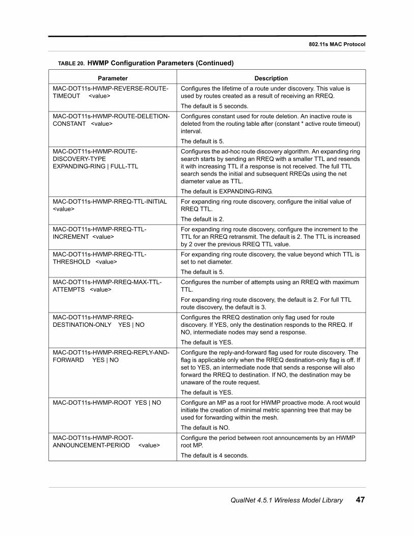
802.11s MAC Protocol
MAC-DOT11s-HWMP-REVERSE-ROUTE-TIMEOUT <value>
Configures the lifetime of a route under discovery. This value is used by routes created as a result of receiving an RREQ.
The default is 5 seconds.
MAC-DOT11s-HWMP-ROUTE-DELETION-CONSTANT <value>
Configures constant used for route deletion. An inactive route is deleted from the routing table after (constant * active route timeout) interval.
The default is 5.
MAC-DOT11s-HWMP-ROUTE-DISCOVERY-TYPE EXPANDING-RING | FULL-TTL
Configures the ad-hoc route discovery algorithm. An expanding ring search starts by sending an RREQ with a smaller TTL and resends it with increasing TTL if a response is not received. The full TTL search sends the initial and subsequent RREQs using the net diameter value as TTL.
The default is EXPANDING-RING.
MAC-DOT11s-HWMP-RREQ-TTL-INITIAL <value>
For expanding ring route discovery, configure the initial value of RREQ TTL.
The default is 2.
MAC-DOT11s-HWMP-RREQ-TTL-INCREMENT <value>
For expanding ring route discovery, configure the increment to the TTL for an RREQ retransmit. The default is 2. The TTL is increased by 2 over the previous RREQ TTL value.
MAC-DOT11s-HWMP-RREQ-TTL-THRESHOLD <value>
For expanding ring route discovery, the value beyond which TTL is set to net diameter.
The default is 5.
MAC-DOT11s-HWMP-RREQ-MAX-TTL-ATTEMPTS <value>
Configures the number of attempts using an RREQ with maximum TTL.
For expanding ring route discovery, the default is 2. For full TTL route discovery, the default is 3.
MAC-DOT11s-HWMP-RREQ-DESTINATION-ONLY YES | NO
Configures the RREQ destination only flag used for route discovery. If YES, only the destination responds to the RREQ. If NO, intermediate nodes may send a response.
The default is YES.
MAC-DOT11s-HWMP-RREQ-REPLY-AND-FORWARD YES | NO
Configure the reply-and-forward flag used for route discovery. The flag is applicable only when the RREQ destination-only flag is off. If set to YES, an intermediate node that sends a response will also forward the RREQ to destination. If NO, the destination may be unaware of the route request.
The default is YES.
MAC-DOT11s-HWMP-ROOT YES | NO Configure an MP as a root for HWMP proactive mode. A root would initiate the creation of minimal metric spanning tree that may be used for forwarding within the mesh.
The default is NO.
MAC-DOT11s-HWMP-ROOT-ANNOUNCEMENT-PERIOD <value>
Configure the period between root announcements by an HWMP root MP.
The default is 4 seconds.
TABLE 20. HWMP Configuration Parameters (Continued)
Parameter Description
QualNet 4.5.1 Wireless Model Library 47
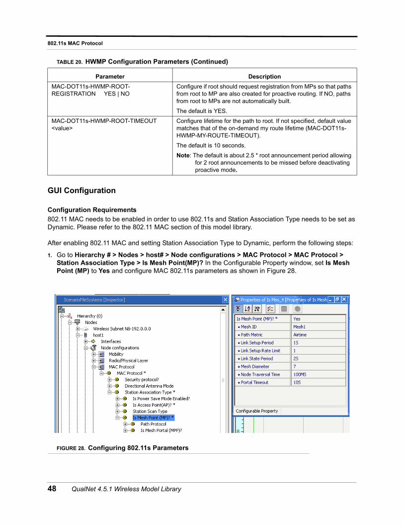
802.11s MAC Protocol
GUI Configuration
Configuration Requirements
802.11 MAC needs to be enabled in order to use 802.11s and Station Association Type needs to be set as Dynamic. Please refer to the 802.11 MAC section of this model library.
After enabling 802.11 MAC and setting Station Association Type to Dynamic, perform the following steps:
1. Go to Hierarchy # > Nodes > host# > Node configurations > MAC Protocol > MAC Protocol > Station Association Type > Is Mesh Point(MP)? In the Configurable Property window, set Is Mesh Point (MP) to Yes and configure MAC 802.11s parameters as shown in Figure 28.
FIGURE 28. Configuring 802.11s Parameters
MAC-DOT11s-HWMP-ROOT-REGISTRATION YES | NO
Configure if root should request registration from MPs so that paths from root to MP are also created for proactive routing. If NO, paths from root to MPs are not automatically built.
The default is YES.
MAC-DOT11s-HWMP-ROOT-TIMEOUT <value>
Configure lifetime for the path to root. If not specified, default value matches that of the on-demand my route lifetime (MAC-DOT11s-HWMP-MY-ROUTE-TIMEOUT).
The default is 10 seconds.
Note: The default is about 2.5 * root announcement period allowing for 2 root announcements to be missed before deactivating proactive mode.
TABLE 20. HWMP Configuration Parameters (Continued)
Parameter Description
48 QualNet 4.5.1 Wireless Model Library
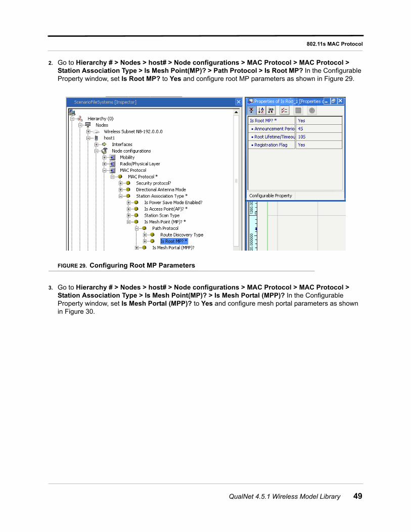
802.11s MAC Protocol
2. Go to Hierarchy # > Nodes > host# > Node configurations > MAC Protocol > MAC Protocol > Station Association Type > Is Mesh Point(MP)? > Path Protocol > Is Root MP? In the Configurable Property window, set Is Root MP? to Yes and configure root MP parameters as shown in Figure 29.
FIGURE 29. Configuring Root MP Parameters
3. Go to Hierarchy # > Nodes > host# > Node configurations > MAC Protocol > MAC Protocol > Station Association Type > Is Mesh Point(MP)? > Is Mesh Portal (MPP)? In the Configurable Property window, set Is Mesh Portal (MPP)? to Yes and configure mesh portal parameters as shown in Figure 30.
QualNet 4.5.1 Wireless Model Library 49
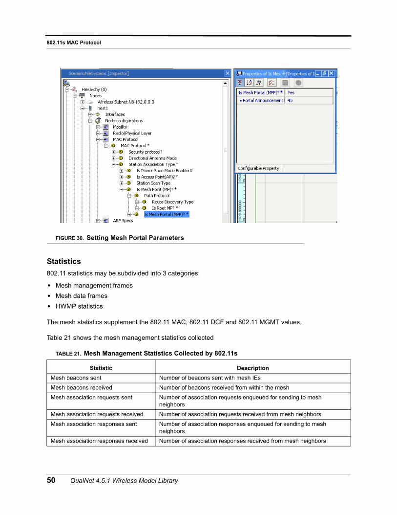
802.11s MAC Protocol
FIGURE 30. Setting Mesh Portal Parameters
Statistics
802.11 statistics may be subdivided into 3 categories:
• Mesh management frames
• Mesh data frames
• HWMP statistics
The mesh statistics supplement the 802.11 MAC, 802.11 DCF and 802.11 MGMT values.
Table 21 shows the mesh management statistics collected
TABLE 21. Mesh Management Statistics Collected by 802.11s
Statistic Description
Mesh beacons sent Number of beacons sent with mesh IEs
Mesh beacons received Number of beacons received from within the mesh
Mesh association requests sent Number of association requests enqueued for sending to mesh neighbors
Mesh association requests received Number of association requests received from mesh neighbors
Mesh association responses sent Number of association responses enqueued for sending to mesh neighbors
Mesh association responses received Number of association responses received from mesh neighbors
50 QualNet 4.5.1 Wireless Model Library
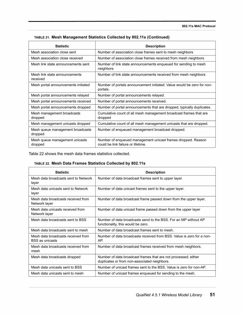
802.11s MAC Protocol
Table 22 shows the mesh data frames statistics collected.
Mesh association close sent Number of association close frames sent to mesh neighbors
Mesh association close received Number of association close frames received from mesh neighbors
Mesh link state announcements sent Number of link state announcements enqueued for sending to mesh neighbors
Mesh link state announcements received
Number of link state announcements received from mesh neighbors
Mesh portal announcements initiated Number of portals announcement initiated. Value would be zero for non-portals.
Mesh portal announcements relayed Number of portal announcements relayed.
Mesh portal announcements received Number of portal announcements received.
Mesh portal announcements dropped Number of portal announcements that are dropped, typically duplicates.
Mesh management broadcasts dropped
Cumulative count of all mesh management broadcast frames that are dropped
Mesh management unicasts dropped Cumulative count of all mesh management unicasts that are dropped.
Mesh queue management broadcasts dropped
Number of enqueued management broadcast dropped.
Mesh queue management unicasts dropped
Number of enqueued management unicast frames dropped. Reason could be link failure or lifetime.
TABLE 22. Mesh Data Frames Statistics Collected by 802.11s
Statistic Description
Mesh data broadcasts sent to Network layer
Number of data broadcast frames sent to upper layer.
Mesh data unicasts sent to Network layer
Number of data unicast frames sent to the upper layer.
Mesh data broadcasts received from Network layer
Number of data broadcast frame passed down from the upper layer.
Mesh data unicasts received from Network layer
Number of data unicast frame passed down from the upper layer
Mesh data broadcasts sent to BSS Number of data broadcasts send to the BSS. For an MP without AP functionality, this would be zero.
Mesh data broadcasts sent to mesh Number of data broadcast frames sent to mesh.
Mesh data broadcasts received from BSS as unicasts
Number of data broadcasts received from BSS. Value is zero for a non-AP.
Mesh data broadcasts received from mesh
Number of data broadcast frames received from mesh neighbors.
Mesh data broadcasts dropped Number of data broadcast frames that are not processed; either duplicates or from non-associated neighbors.
Mesh data unicasts sent to BSS Number of unicast frames sent to the BSS. Value is zero for non-AP.
Mesh data unicasts sent to mesh Number of unicast frames enqueued for sending to the mesh.
TABLE 21. Mesh Management Statistics Collected by 802.11s (Continued)
Statistic Description
QualNet 4.5.1 Wireless Model Library 51
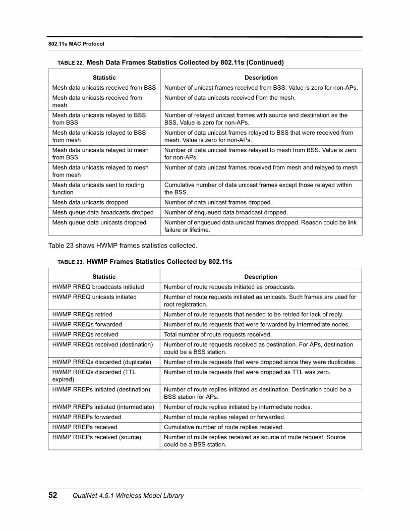
802.11s MAC Protocol
Table 23 shows HWMP frames statistics collected.
Mesh data unicasts received from BSS Number of unicast frames received from BSS. Value is zero for non-APs.
Mesh data unicasts received from mesh
Number of data unicasts received from the mesh.
Mesh data unicasts relayed to BSS from BSS
Number of relayed unicast frames with source and destination as the BSS. Value is zero for non-APs.
Mesh data unicasts relayed to BSS from mesh
Number of data unicast frames relayed to BSS that were received from mesh. Value is zero for non-APs.
Mesh data unicasts relayed to mesh from BSS
Number of data unicast frames relayed to mesh from BSS. Value is zero for non-APs.
Mesh data unicasts relayed to mesh from mesh
Number of data unicast frames received from mesh and relayed to mesh
Mesh data unicasts sent to routing function
Cumulative number of data unicast frames except those relayed within the BSS.
Mesh data unicasts dropped Number of data unicast frames dropped.
Mesh queue data broadcasts dropped Number of enqueued data broadcast dropped.
Mesh queue data unicasts dropped Number of enqueued data unicast frames dropped. Reason could be link failure or lifetime.
TABLE 23. HWMP Frames Statistics Collected by 802.11s
Statistic Description
HWMP RREQ broadcasts initiated Number of route requests initiated as broadcasts.
HWMP RREQ unicasts initiated Number of route requests initiated as unicasts. Such frames are used for root registration.
HWMP RREQs retried Number of route requests that needed to be retried for lack of reply.
HWMP RREQs forwarded Number of route requests that were forwarded by intermediate nodes.
HWMP RREQs received Total number of route requests received.
HWMP RREQs received (destination) Number of route requests received as destination. For APs, destination could be a BSS station.
HWMP RREQs discarded (duplicate) Number of route requests that were dropped since they were duplicates.
HWMP RREQs discarded (TTL expired)
Number of route requests that were dropped as TTL was zero.
HWMP RREPs initiated (destination) Number of route replies initiated as destination. Destination could be a BSS station for APs.
HWMP RREPs initiated (intermediate) Number of route replies initiated by intermediate nodes.
HWMP RREPs forwarded Number of route replies relayed or forwarded.
HWMP RREPs received Cumulative number of route replies received.
HWMP RREPs received (source) Number of route replies received as source of route request. Source could be a BSS station.
TABLE 22. Mesh Data Frames Statistics Collected by 802.11s (Continued)
Statistic Description
52 QualNet 4.5.1 Wireless Model Library
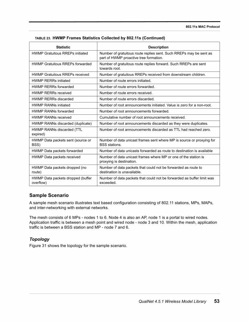
802.11s MAC Protocol
Sample Scenario
A sample mesh scenario illustrates text based configuration consisting of 802.11 stations, MPs, MAPs, and inter-networking with external networks.
The mesh consists of 6 MPs - nodes 1 to 6. Node 4 is also an AP, node 1 is a portal to wired nodes. Application traffic is between a mesh point and wired node - node 3 and 10. Within the mesh, application traffic is between a BSS station and MP - node 7 and 6.
Topology
Figure 31 shows the topology for the sample scenario.
HWMP Gratuitous RREPs initiated Number of gratuitous route replies sent. Such RREPs may be sent as part of HWMP proactive tree formation.
HWMP Gratuitous RREPs forwarded Number of gratuitous route replies forward. Such RREPs are sent towards root.
HWMP Gratuitous RREPs received Number of gratuitous RREPs received from downstream children.
HWMP RERRs initiated Number of route errors initiated.
HWMP RERRs forwarded Number of route errors forwarded.
HWMP RERRs received Number of route errors received.
HWMP RERRs discarded Number of route errors discarded.
HWMP RANNs initiated Number of root announcements initiated. Value is zero for a non-root.
HWMP RANNs forwarded Number of root announcements forwarded.
HWMP RANNs received Cumulative number of root announcements received.
HWMP RANNs discarded (duplicate) Number of root announcements discarded as they were duplicates.
HWMP RANNs discarded (TTL expired)
Number of root announcements discarded as TTL had reached zero.
HWMP Data packets sent (source or BSS)
Number of data unicast frames sent where MP is source or proxying for BSS stations.
HWMP Data packets forwarded Number of data unicasts forwarded as route to destination is available
HWMP Data packets received Number of data unicast frames where MP or one of the station is proxying is destination.
HWMP Data packets dropped (no route)
Number of data packets that could not be forwarded as route to destination is unavailable.
HWMP Data packets dropped (buffer overflow)
Number of data packets that could not be forwarded as buffer limit was exceeded.
TABLE 23. HWMP Frames Statistics Collected by 802.11s (Continued)
Statistic Description
QualNet 4.5.1 Wireless Model Library 53
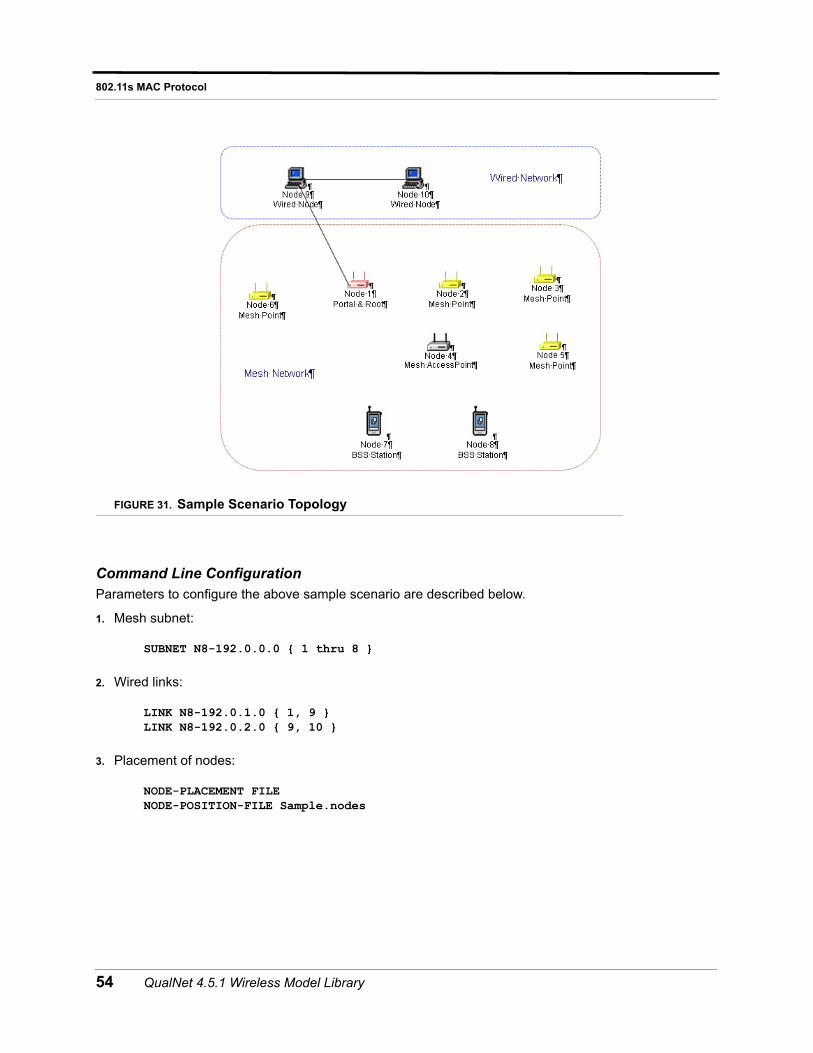
802.11s MAC Protocol
FIGURE 31. Sample Scenario Topology
Command Line ConfigurationParameters to configure the above sample scenario are described below.
1. Mesh subnet:
SUBNET N8-192.0.0.0 { 1 thru 8 }
2. Wired links:
LINK N8-192.0.1.0 { 1, 9 }LINK N8-192.0.2.0 { 9, 10 }
3. Placement of nodes:
NODE-PLACEMENT FILENODE-POSITION-FILE Sample.nodes
54 QualNet 4.5.1 Wireless Model Library
802.11s MAC Protocol
4. MAC Parameters
For the mesh: 802.11 value are configured to use the infrastructure mode:
[ N8-192.0.0.0 ] MAC-PROTOCOL MACDOT11[ N8-192.0.0.0 ] MAC-DOT11-ASSOCIATION DYNAMIC[ N8-192.0.0.0 ] MAC-DOT11-SCAN-TYPE PASSIVE
The rest of 802.11 values are at default.
For the wired links, default values are:
LINK-PROPAGATION-DELAY 1MSLINK-BANDWIDTH 10000000
5. 802.11s Device Parameters
Mesh services are enabled with:
[1 2 3 4 5 6 ] MAC-DOT11s-MESH-POINT YES
Access point services are enabled at node 4 with:
[ 4 ] MAC-DOT11-AP YES
Node 1 is configured as a portal with:
[ 1 ] MAC-DOT11s-MESH-PORTAL YES
Rest of the 802.11s values are at default.
6. HWMP Parameters
Default values are used; except that proactive routes are enabled by specifying node 10 as an HWMP root.
[ 1 ] MAC-DOT11s-HWMP-ROOT YES
7. Routing
For traffic within a mesh, a routing protocol is not necessary as default routes are set within the code.
For a mesh-only scenario, routing could be turned off globally or for the subnet with either:
ROUTING-PROTOCOL NONE[ N8-192.0.0.0 ] ROUTING-PROTOCOL NONE
For inter-networking, various approaches are available depending on the routing protocol used beyond the mesh:
• Configure a wired routing protocol at all interfaces of mesh portal, not just the interface. Candidate protocols include OSPFv2, RIP, Bellman-Ford. All of them are capable to support aggregated routing information. Such a configuration would transmit routing packets on the mesh interface of the mesh portal.
• Configure OSPFv2 routing and configure OSPFv2 at mesh portal to advertise external route. OSPFv2 has a parameter to configure external route file. In this file, add a route for the mesh. So OSPFv2 routing at mesh portal will advertise this route information to external network.
QualNet 4.5.1 Wireless Model Library 55
802.11s MAC Protocol
• Configure a routing as OLSR, OLSRv2, etc. At the mesh portal, enable it to advertise route information for attached network.
Within the mesh, the portal interface is set as the default gateway. For example, with node 10 as the por-tal with IP address as 192.0.0.1:
[2 3 4 5 6 7 8] DEFAULT-ROUTE YES[2 3 4 5 6 7 8] DEFAULT-ROUTE-FILE Sample.routes-default
The contents of the Sample.routes-default file follow the format:
<nodeId> <destAddress> <nextHop> [outgoing_interface] [cost]
For example, each mesh node that is not a mesh portal has a line similar to:
2 N32-0.0.0.0 192.0.0.1
8. Application Layer
Desired application traffic is specified in a separate file given by:
APP-CONFIG-FILE Sample.app
Example contents of Sample.app are:
CBR 3 10 100 1000 100MS 125 0 PRECEDENCE 0CBR 10 3 100 1000 100MS 145 0 PRECEDENCE 0FTP/GENERIC 3 10 500 512 165 0 PRECEDENCE 0FTP/GENERIC 7 6 1000 512 185 0 PRECEDENCE 0
GUI ConfigurationTo configure the sample scenario in the GUI, perform the following steps.
1. Go to ConfigSettings > General > Terrain. Set the terrain dimension to 1200 x 1000.
2. Place 8 mesh nodes on the canvas. Place a wireless subnet and link the mesh nodes to it.
3. Place two nodes (nodes 9 and 10) on the canvas. Connect nodes 1 and 9, and nodes 9 and 10 by point-to-point links.
56 QualNet 4.5.1 Wireless Model Library
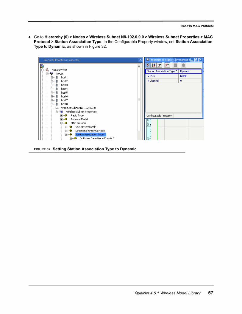
802.11s MAC Protocol
4. Go to Hierarchy (0) > Nodes > Wireless Subnet N8-192.0.0.0 > Wireless Subnet Properties > MAC Protocol > Station Association Type. In the Configurable Property window, set Station Association Type to Dynamic, as shown in Figure 32.
FIGURE 32. Setting Station Association Type to Dynamic
QualNet 4.5.1 Wireless Model Library 57
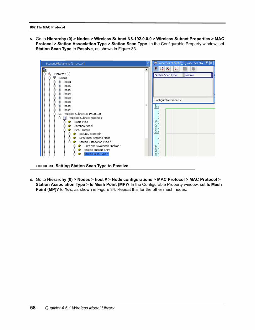
802.11s MAC Protocol
5. Go to Hierarchy (0) > Nodes > Wireless Subnet N8-192.0.0.0 > Wireless Subnet Properties > MAC Protocol > Station Association Type > Station Scan Type. In the Configurable Property window, set Station Scan Type to Passive, as shown in Figure 33.
FIGURE 33. Setting Station Scan Type to Passive
6. Go to Hierarchy (0) > Nodes > host # > Node configurations > MAC Protocol > MAC Protocol > Station Association Type > Is Mesh Point (MP)? In the Configurable Property window, set Is Mesh Point (MP)? to Yes, as shown in Figure 34. Repeat this for the other mesh nodes.
58 QualNet 4.5.1 Wireless Model Library
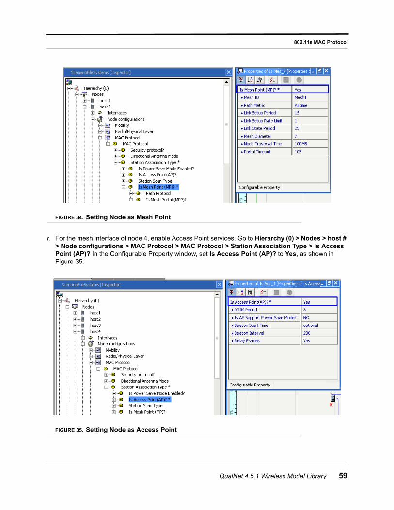
802.11s MAC Protocol
FIGURE 34. Setting Node as Mesh Point
7. For the mesh interface of node 4, enable Access Point services. Go to Hierarchy (0) > Nodes > host # > Node configurations > MAC Protocol > MAC Protocol > Station Association Type > Is Access Point (AP)? In the Configurable Property window, set Is Access Point (AP)? to Yes, as shown in Figure 35.
FIGURE 35. Setting Node as Access Point
QualNet 4.5.1 Wireless Model Library 59
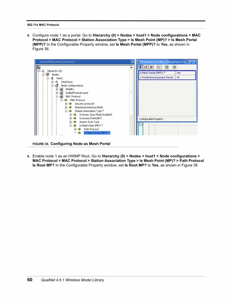
802.11s MAC Protocol
8. Configure node 1 as a portal. Go to Hierarchy (0) > Nodes > host1 > Node configurations > MAC Protocol > MAC Protocol > Station Association Type > Is Mesh Point (MP)? > Is Mesh Portal (MPP)? In the Configurable Property window, set Is Mesh Portal (MPP)? to Yes, as shown in Figure 36.
FIGURE 36. Configuring Node as Mesh Portal
9. Enable node 1 as an HWMP Root. Go to Hierarchy (0) > Nodes > host1 > Node configurations > MAC Protocol > MAC Protocol > Station Association Type > Is Mesh Point (MP)? > Path Protocol Is Root MP? In the Configurable Property window, set Is Root MP? to Yes, as shown in Figure 36
60 QualNet 4.5.1 Wireless Model Library
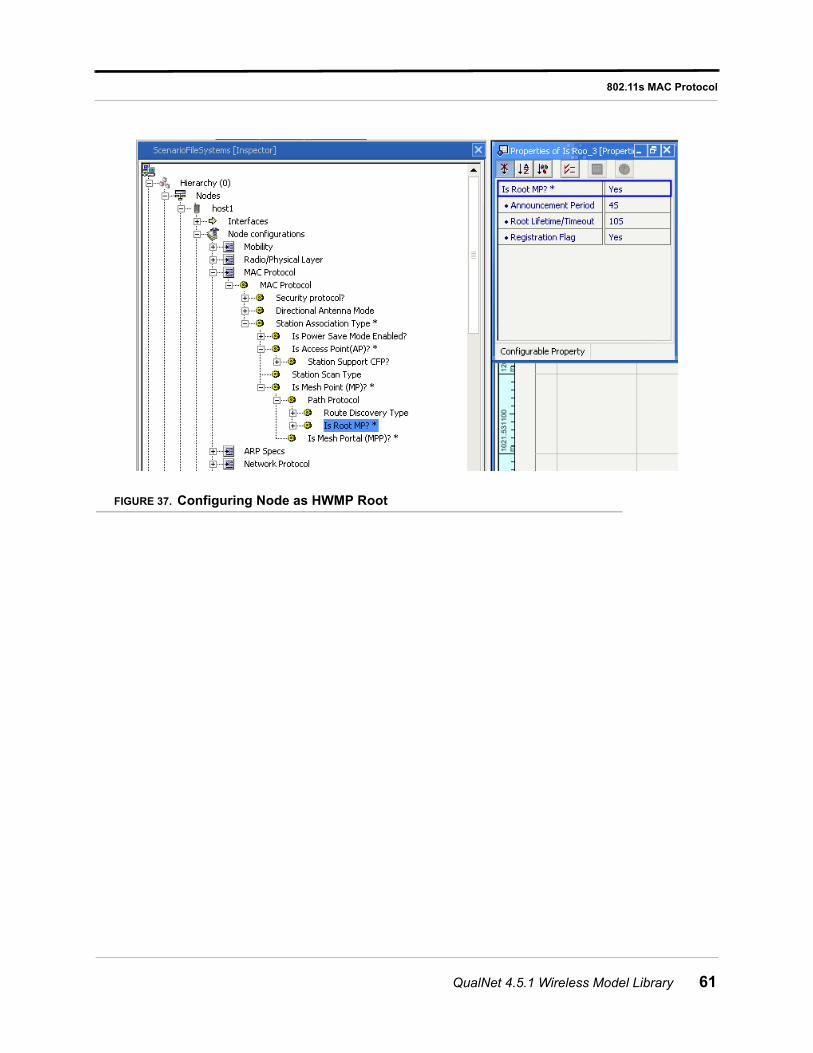
802.11s MAC Protocol
FIGURE 37. Configuring Node as HWMP Root
QualNet 4.5.1 Wireless Model Library 61
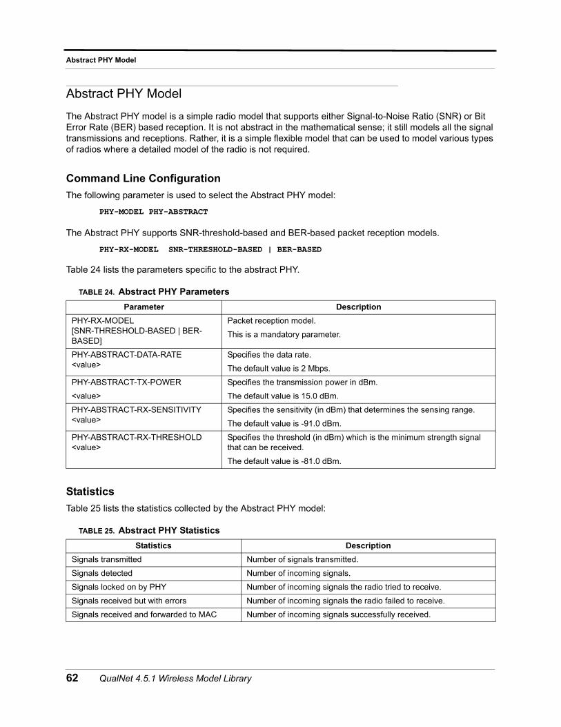
Abstract PHY Model
Abstract PHY Model
The Abstract PHY model is a simple radio model that supports either Signal-to-Noise Ratio (SNR) or Bit Error Rate (BER) based reception. It is not abstract in the mathematical sense; it still models all the signal transmissions and receptions. Rather, it is a simple flexible model that can be used to model various types of radios where a detailed model of the radio is not required.
Command Line Configuration
The following parameter is used to select the Abstract PHY model:
PHY-MODEL PHY-ABSTRACT
The Abstract PHY supports SNR-threshold-based and BER-based packet reception models.
PHY-RX-MODEL SNR-THRESHOLD-BASED | BER-BASED
Table 24 lists the parameters specific to the abstract PHY.
Statistics
Table 25 lists the statistics collected by the Abstract PHY model:
TABLE 24. Abstract PHY Parameters
Parameter Description
PHY-RX-MODEL [SNR-THRESHOLD-BASED | BER-BASED]
Packet reception model.
This is a mandatory parameter.
PHY-ABSTRACT-DATA-RATE <value>
Specifies the data rate.
The default value is 2 Mbps.
PHY-ABSTRACT-TX-POWER
<value>
Specifies the transmission power in dBm.
The default value is 15.0 dBm.
PHY-ABSTRACT-RX-SENSITIVITY <value>
Specifies the sensitivity (in dBm) that determines the sensing range.
The default value is -91.0 dBm.
PHY-ABSTRACT-RX-THRESHOLD <value>
Specifies the threshold (in dBm) which is the minimum strength signal that can be received.
The default value is -81.0 dBm.
TABLE 25. Abstract PHY Statistics
Statistics Description
Signals transmitted Number of signals transmitted.
Signals detected Number of incoming signals.
Signals locked on by PHY Number of incoming signals the radio tried to receive.
Signals received but with errors Number of incoming signals the radio failed to receive.
Signals received and forwarded to MAC Number of incoming signals successfully received.
62 QualNet 4.5.1 Wireless Model Library
Ad-Hoc On Demand Distance Vector (AODV) Routing Protocol
Ad-Hoc On Demand Distance Vector (AODV) Routing Protocol
AODV protocol is specially used for mobile ad hoc networks. It provides a quick adaptation to dynamic link condition, link fault, low processing and memory usage overhead. The important feature of AODV is its use of Sequence Number to prevent routing loops. Loops prevent, finding of more than one route to a particular destination, which is resolved by using the sequence number.
Command Line Configuration
To select AODV as the routing protocol, specify the following parameter(s) in the scenario configuration (.config) file:
• For an IPv4 node, use the following parameter:
ROUTING-PROTOCOL AODV
• For an IPv6 node, use either of the following parameters:
ROUTING-PROTOCOL AODV
orROUTING-PROTOCOL-IPv6 AODV
• For a dual IP-node, use both the following parameter:
ROUTING-PROTOCOL AODV
andROUTING-PROTOCOL-IPv6 AODV
AODV configuration parameters are described in Table 26.
TABLE 26. AODV Parameters
Parameter Description
AODV-DEST-ONLY-NODE YES | NO
Enables a particular node to set the destination-only-node while sending RREQ, you must specify the following configuration in the *.config file as follows.
The default value is NO.
ROUTING STATISTICS YES | NO
Enables AODV to collect the statistics and store the statistics after completing the simulation, you must specify the following configuration in the *.config file as follows.
The default value is YES.
AODV-NET-DIAMETER <integer> Specifies the maximum possible number of hops between two nodes in the network.
The default value is 35
AODV-NODE TRAVERSAL-TIME <time> Specifies the conservative estimate of the average one-hop traversal time for packets and should include queuing, transmission, propagation and other delays.
The default value is 40 ms
QualNet 4.5.1 Wireless Model Library 63
Ad-Hoc On Demand Distance Vector (AODV) Routing Protocol
AODV-ACTIVE-ROUTE-TIMEOUT <time>
Specifies the Timeout time for an active route; each time a data packet is sent, the lifetime of that route is updated to this value.
The default value is 3000ms.
AODV-MY-ROUTE-TIMEOUT <time> Specifies the destination of a RREQ replies with AODV-MY-ROUTE-TIMEOUT as the lifetime of the route.
The default value is 2 * AODV-ACTIVE-ROUTE-TIMEOUT
AODV-PROCESS-HELLOYES | NO
If set to YES, specifies a node will send a hello message, if there is no broadcast within the last hello interval.
The default value is NO
AODV-HELLO-INTERVAL <time>
Specifies the lifetime of a hello message using the following equation: AODV-ALLOWED_HELLO_LOSS * AODV-HELLO_INTERVAL.
The default value is 1000ms
AODV-ALLOWED-HELLO-LOSS <value> Specifies the maximum number of times for AODV to repeat the expanded ring search for a destination, if no Route Reply is received within the specified time.
The default value is 2
AODV-RREQ-RETRIES <integer> Specifies the maximum number of times for AODV to repeat the expanded ring search for a destination, if no Route Reply is received within the specified amount of time.
The default value is 2
AODV-ROUTE-DELECTION-CONSTANT <integer>
Specifies a constant, which is used for calculating the time after which an active route must be deleted. After timeout of an active route, the route is deleted from the routing table after a time period of K * Max(AODV-ACTIVE_ROUTE_TIMEOUT,AODV-ALLOWED_HELLO_LOSS * AODV-HELLO_INTERVAL). Here, K is the AODV-ROUTE-DELETION-CONSTANT.
The default value is 5
AODV-LOCAL-REPAIRYES | NO
If set to YES, specifies the node will try to locally Repair a broken route.
The default value is NO.
AODV-SEARCH-BETTER-ROUTE YES | NO
If a route source node gets a route error message, it initiates a new Route Request for the destination if the value is set to YES.
The default value is NO.
AODV-BUFFER-MAX-PACKET <integer> Specifies the maximum number of packets for the message buffer of AODV. If the buffer reaches its maximum, the incoming packets for the buffer is dropped.
The default value is 100.
AODV-BUFFER-MAX-BYTE <integer> If nothing is specified, the buffer overflow will be checked by the number of packets in the buffer. If some value is specified, incoming packets are dropped if the total of the incoming packet size and current size of the buffer exceeds this value.
The default value is 0.
TABLE 26. AODV Parameters (Continued)
Parameter Description
64 QualNet 4.5.1 Wireless Model Library
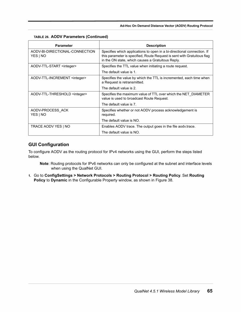
Ad-Hoc On Demand Distance Vector (AODV) Routing Protocol
GUI Configuration
To configure AODV as the routing protocol for IPv4 networks using the GUI, perform the steps listed below.
Note: Routing protocols for IPv6 networks can only be configured at the subnet and interface levels when using the QualNet GUI.
1. Go to ConfigSettings > Network Protocols > Routing Protocol > Routing Policy. Set Routing Policy to Dynamic in the Configurable Property window, as shown in Figure 38.
AODV-BI-DIRECTIONAL-CONNECTION YES | NO
Specifies which applications to open in a bi-directional connection. If this parameter is specified, Route Request is sent with Gratuitous flag in the ON state, which causes a Gratuitous Reply.
AODV-TTL-START <integer> Specifies the TTL value when initiating a route request.
The default value is 1.
AODV-TTL-INCREMENT <integer> Specifies the value by which the TTL is incremented, each time when a Request is retransmitted.
The default value is 2.
AODV-TTL-THRESHOLD <integer> Specifies the maximum value of TTL over which the NET_DIAMETER value is used to broadcast Route Request.
The default value is 7.
AODV-PROCESS_ACK YES | NO
Specifies whether or not AODV process acknowledgement is required.
The default value is NO.
TRACE AODV YES | NO Enables AODV trace. The output goes in the file aodv.trace.
The default value is NO.
TABLE 26. AODV Parameters (Continued)
Parameter Description
QualNet 4.5.1 Wireless Model Library 65
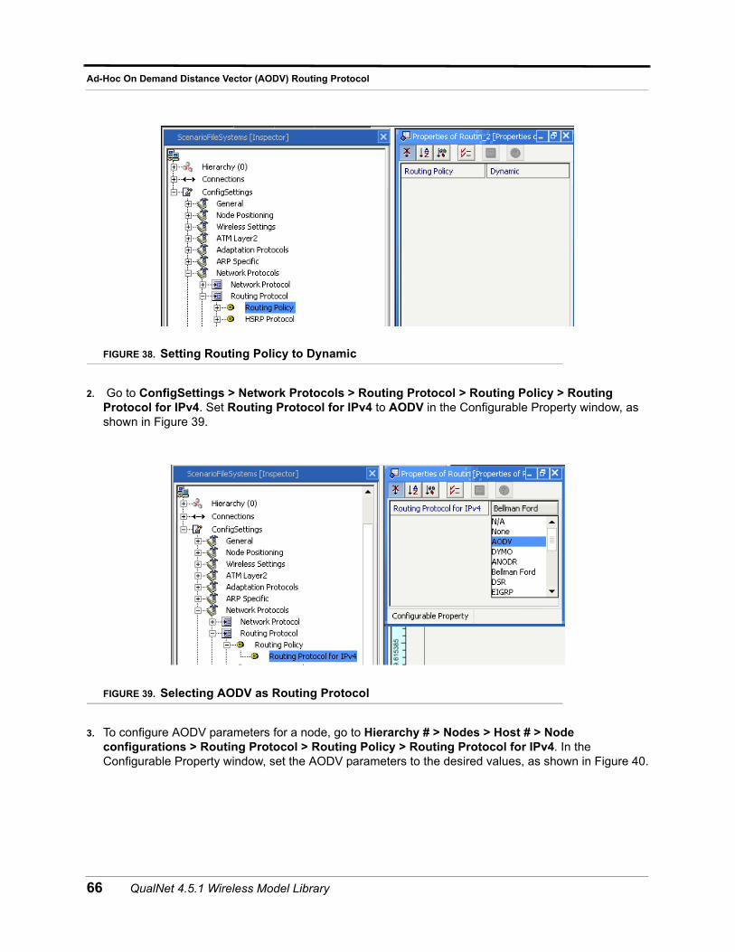
Ad-Hoc On Demand Distance Vector (AODV) Routing Protocol
FIGURE 38. Setting Routing Policy to Dynamic
2. Go to ConfigSettings > Network Protocols > Routing Protocol > Routing Policy > Routing Protocol for IPv4. Set Routing Protocol for IPv4 to AODV in the Configurable Property window, as shown in Figure 39.
FIGURE 39. Selecting AODV as Routing Protocol
3. To configure AODV parameters for a node, go to Hierarchy # > Nodes > Host # > Node configurations > Routing Protocol > Routing Policy > Routing Protocol for IPv4. In the Configurable Property window, set the AODV parameters to the desired values, as shown in Figure 40.
66 QualNet 4.5.1 Wireless Model Library
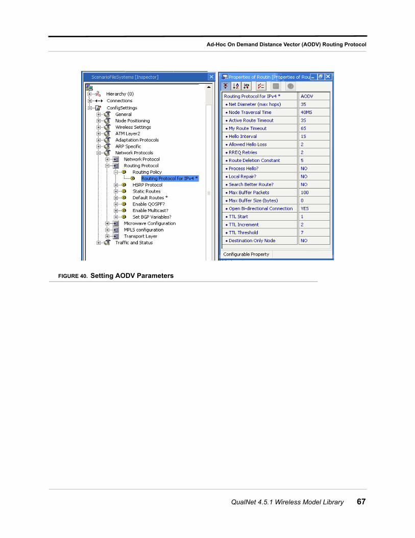
Ad-Hoc On Demand Distance Vector (AODV) Routing Protocol
FIGURE 40. Setting AODV Parameters
QualNet 4.5.1 Wireless Model Library 67
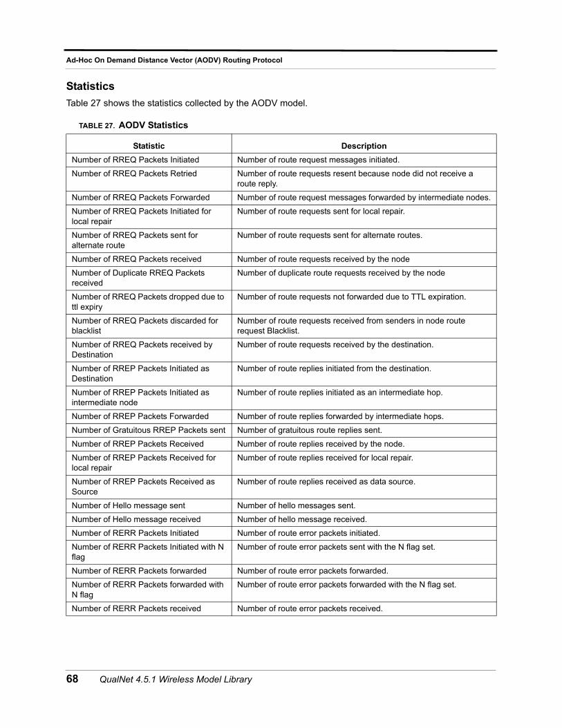
Ad-Hoc On Demand Distance Vector (AODV) Routing Protocol
Statistics
Table 27 shows the statistics collected by the AODV model.
TABLE 27. AODV Statistics
Statistic Description
Number of RREQ Packets Initiated Number of route request messages initiated.
Number of RREQ Packets Retried Number of route requests resent because node did not receive a route reply.
Number of RREQ Packets Forwarded Number of route request messages forwarded by intermediate nodes.
Number of RREQ Packets Initiated for local repair
Number of route requests sent for local repair.
Number of RREQ Packets sent for alternate route
Number of route requests sent for alternate routes.
Number of RREQ Packets received Number of route requests received by the node
Number of Duplicate RREQ Packets received
Number of duplicate route requests received by the node
Number of RREQ Packets dropped due to ttl expiry
Number of route requests not forwarded due to TTL expiration.
Number of RREQ Packets discarded for blacklist
Number of route requests received from senders in node route request Blacklist.
Number of RREQ Packets received by Destination
Number of route requests received by the destination.
Number of RREP Packets Initiated as Destination
Number of route replies initiated from the destination.
Number of RREP Packets Initiated as intermediate node
Number of route replies initiated as an intermediate hop.
Number of RREP Packets Forwarded Number of route replies forwarded by intermediate hops.
Number of Gratuitous RREP Packets sent Number of gratuitous route replies sent.
Number of RREP Packets Received Number of route replies received by the node.
Number of RREP Packets Received for local repair
Number of route replies received for local repair.
Number of RREP Packets Received as Source
Number of route replies received as data source.
Number of Hello message sent Number of hello messages sent.
Number of Hello message received Number of hello message received.
Number of RERR Packets Initiated Number of route error packets initiated.
Number of RERR Packets Initiated with N flag
Number of route error packets sent with the N flag set.
Number of RERR Packets forwarded Number of route error packets forwarded.
Number of RERR Packets forwarded with N flag
Number of route error packets forwarded with the N flag set.
Number of RERR Packets received Number of route error packets received.
68 QualNet 4.5.1 Wireless Model Library

Ad-Hoc On Demand Distance Vector (AODV) Routing Protocol
Sample Scenario
Scenario DescriptionFigure 41 shows an example of how you can use the AODV routing protocol in the QualNet configuration file. This example is a six-node ad-hoc scenario with the Routing Protocol set to AODV. The application is configured between node 1 and node 6, node 1 sends 100 packets to node 6, and each packet is 512 bytes.
FIGURE 41. Example AODV Scenario
Number of RERR Packets received with N flag
Number of route error packets received with the N flag set.
Number of RERR Packets discarded Number of route error packets discarded.
Number of Data packets sent as Source Number of data packets sent as the source of the data.
Number of Data Packets Forwarded Number of data packets forwarded.
Number of Data Packets Received Number of data packets received as the destination of the data.
Number of Data Packets Dropped for no route
Number of data packets dropped due to lack of route.
Number of Data Packets Dropped for buffer overflow
Number of data packets dropped due to buffer overflow.
Number of Routes Selected Number of routes added to the route cache.
Total Hop Counts for all routes Aggregate sum of the hop counts of all routes added to the route cache.
Number of Packets Dropped for exceeding Maximum Hop Count
Number of data packets dropped because maximum hop count exceeded.
Number of times link broke Number of times link is broken between nodes.
TABLE 27. AODV Statistics (Continued)
Statistic Description
QualNet 4.5.1 Wireless Model Library 69
Ad-Hoc On Demand Distance Vector (AODV) Routing Protocol
Command Line Configuration
In the *.config file, specify the following parameters.
SIMULATION-TIME 10M// The scenario is executed for a simulation time of 10minutes.ROUTING-PROTOCOL AODVAODV-NET-DIAMETER 35AODV-NODE-TRAVERSAL-TIME 40msAODV-ACTIVE-ROUTE-TIMEOUT 300msAODV-MY-ROUTE-TIMEOUT 600msAODV-HELLO-INTERVAL 1000msAODV-RREQ-RETRIES 2AODV-ROUTE-DELETION-CONSTANT 5AODV-PROCESS-HELLO NOAODV-ALLOWED-HELLO-LOSS 2AODV-LOCAL-REPAIR NOAODV-SEARCH-BETTER-ROUTE NOAODV-BUFFER-MAX-PACKET 100AODV-BUFFER-MAX-BYTE 0AODV-OPEN-BI-DIRECTIONAL-CONNECTION 1AODV-TTL-START 1AODV-TTL-INCREMENT 2AODV-TTL-THRESHOLD 7AODV-DEST-ONLY-NODE NO
GUI Configuration
Creating a New Scenario
To create a new scenario, you must perform the following steps:
1. Create a new scenario. Place six default nodes as shown in Figure 41.
2. Go to ConfigSettings > Network Protocols > Routing Protocol > Routing Policy. Set Routing Policy to Dynamic.
3. Go to ConfigSettings > Network Protocol > Routing Protocol > Routing Policy > Routing Protocol. Set Routing Protocol to AODV. In the Configurable Property window, set the AODV parameters.
4. Click Applications from the Scenario Designer window.
a. Select CBR and set the application between node 1 and node 6.
b. Set the CBR parameters in the Configurable Property window.
70 QualNet 4.5.1 Wireless Model Library
Aloha MAC Protocol
Aloha MAC Protocol
Aloha is a wireless random access MAC protocol that transmits data whenever there is data to send (no carrier sensing). If no acknowledgement is received, the source retransmits at a later time.
Command Line Configuration
To select Aloha as the MAC protocol, place the following entry in the *.config file:
MAC-PROTOCOL ALOHA
Statistics
Aloha MAC collects the statistics shown in Table 28.
TABLE 28. Aloha Statistics
Statistics Description
Packets Sent to Channel Number of data packets sent to channel
Packets Received from Channel Number of data packets received from channel
Packets Dropped Number of data packets dropped
QualNet 4.5.1 Wireless Model Library 71
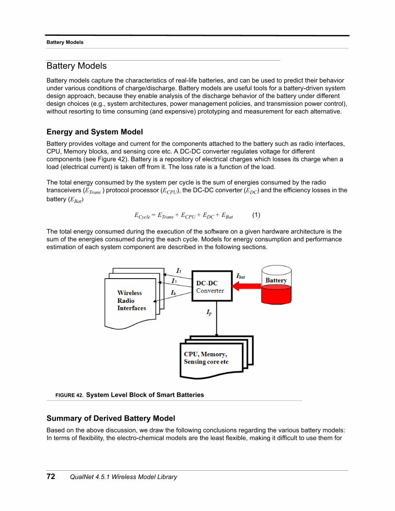
Battery Models
Battery Models
Battery models capture the characteristics of real-life batteries, and can be used to predict their behavior under various conditions of charge/discharge. Battery models are useful tools for a battery-driven system design approach, because they enable analysis of the discharge behavior of the battery under different design choices (e.g., system architectures, power management policies, and transmission power control), without resorting to time consuming (and expensive) prototyping and measurement for each alternative.
Energy and System Model
Battery provides voltage and current for the components attached to the battery such as radio interfaces, CPU, Memory blocks, and sensing core etc. A DC-DC converter regulates voltage for different components (see Figure 42). Battery is a repository of electrical charges which losses its charge when a load (electrical current) is taken off from it. The loss rate is a function of the load.
The total energy consumed by the system per cycle is the sum of energies consumed by the radio transceivers (ETrans ) protocol processor (ECPU), the DC-DC converter (EDC) and the efficiency losses in the battery (EBat)
ECycle = ETrans + ECPU + EDC + EBat (1)
The total energy consumed during the execution of the software on a given hardware architecture is the sum of the energies consumed during the each cycle. Models for energy consumption and performance estimation of each system component are described in the following sections.
FIGURE 42. System Level Block of Smart Batteries
Summary of Derived Battery Model
Based on the above discussion, we draw the following conclusions regarding the various battery models: In terms of flexibility, the electro-chemical models are the least flexible, making it difficult to use them for
72 QualNet 4.5.1 Wireless Model Library
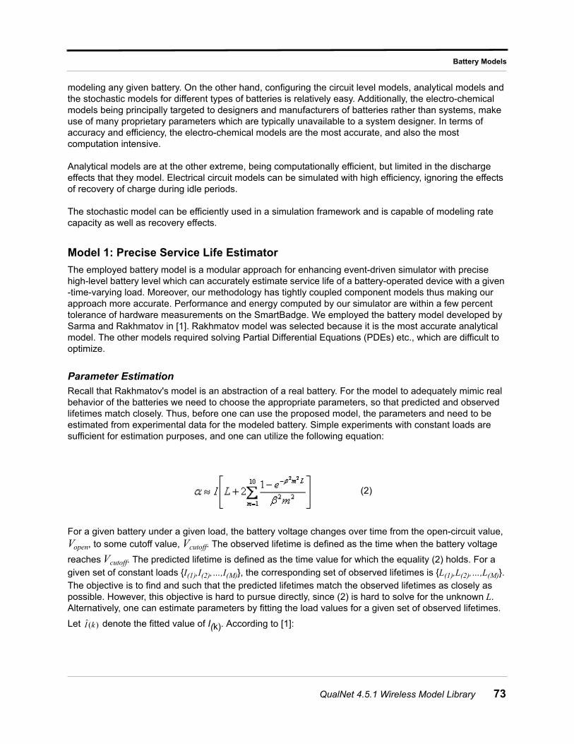
Battery Models
modeling any given battery. On the other hand, configuring the circuit level models, analytical models and the stochastic models for different types of batteries is relatively easy. Additionally, the electro-chemical models being principally targeted to designers and manufacturers of batteries rather than systems, make use of many proprietary parameters which are typically unavailable to a system designer. In terms of accuracy and efficiency, the electro-chemical models are the most accurate, and also the most computation intensive.
Analytical models are at the other extreme, being computationally efficient, but limited in the discharge effects that they model. Electrical circuit models can be simulated with high efficiency, ignoring the effects of recovery of charge during idle periods.
The stochastic model can be efficiently used in a simulation framework and is capable of modeling rate capacity as well as recovery effects.
Model 1: Precise Service Life Estimator
The employed battery model is a modular approach for enhancing event-driven simulator with precise high-level battery level which can accurately estimate service life of a battery-operated device with a given -time-varying load. Moreover, our methodology has tightly coupled component models thus making our approach more accurate. Performance and energy computed by our simulator are within a few percent tolerance of hardware measurements on the SmartBadge. We employed the battery model developed by Sarma and Rakhmatov in [1]. Rakhmatov model was selected because it is the most accurate analytical model. The other models required solving Partial Differential Equations (PDEs) etc., which are difficult to optimize.
Parameter EstimationRecall that Rakhmatov's model is an abstraction of a real battery. For the model to adequately mimic real behavior of the batteries we need to choose the appropriate parameters, so that predicted and observed lifetimes match closely. Thus, before one can use the proposed model, the parameters and need to be estimated from experimental data for the modeled battery. Simple experiments with constant loads are sufficient for estimation purposes, and one can utilize the following equation:
For a given battery under a given load, the battery voltage changes over time from the open-circuit value, Vopen, to some cutoff value, Vcutoff. The observed lifetime is defined as the time when the battery voltage
reaches Vcutoff. The predicted lifetime is defined as the time value for which the equality (2) holds. For a given set of constant loads {I(1),I(2),…,I(M)}, the corresponding set of observed lifetimes is {L(1),L(2),…,L(M)}. The objective is to find and such that the predicted lifetimes match the observed lifetimes as closely as possible. However, this objective is hard to pursue directly, since (2) is hard to solve for the unknown L. Alternatively, one can estimate parameters by fitting the load values for a given set of observed lifetimes.
Let denote the fitted value of I(k). According to [1]:
(2)
)(ˆ kI
QualNet 4.5.1 Wireless Model Library 73
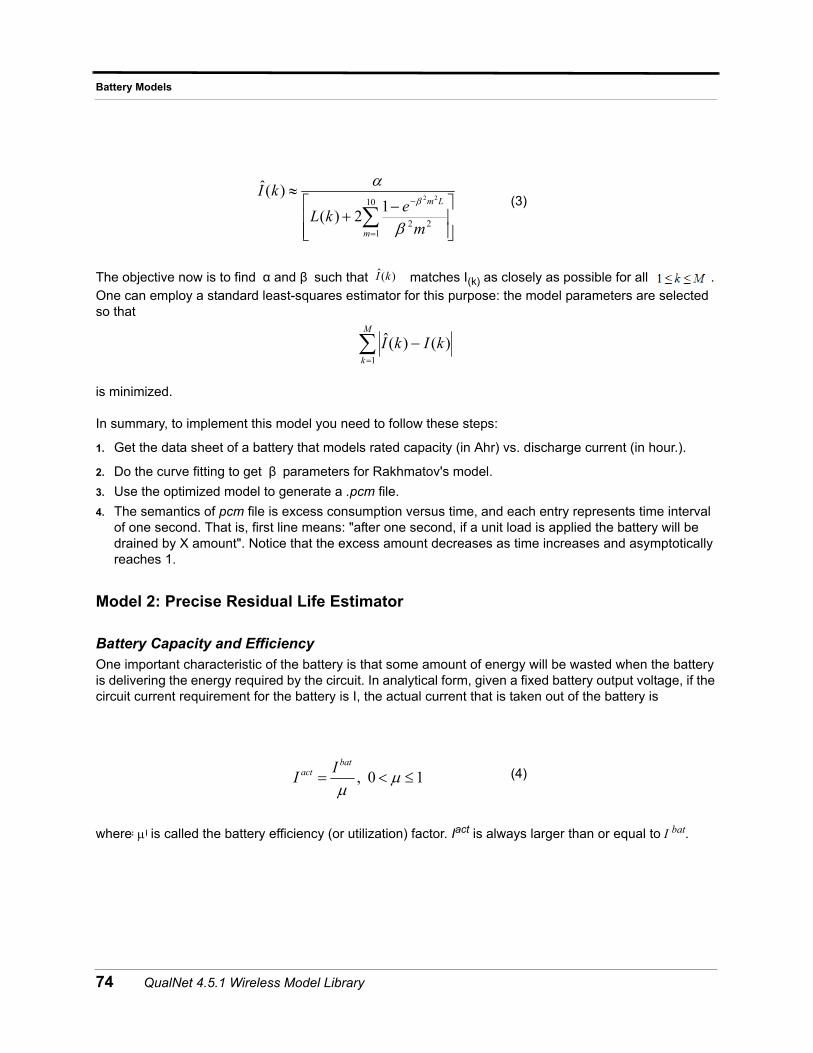
Battery Models
The objective now is to find such that matches I(k) as closely as possible for all . One can employ a standard least-squares estimator for this purpose: the model parameters are selected so that
is minimized.
In summary, to implement this model you need to follow these steps:
1. Get the data sheet of a battery that models rated capacity (in Ahr) vs. discharge current (in hour.).
2. Do the curve fitting to get parameters for Rakhmatov's model.
3. Use the optimized model to generate a .pcm file.
4. The semantics of pcm file is excess consumption versus time, and each entry represents time interval of one second. That is, first line means: "after one second, if a unit load is applied the battery will be drained by X amount". Notice that the excess amount decreases as time increases and asymptotically reaches 1.
Model 2: Precise Residual Life Estimator
Battery Capacity and Efficiency
One important characteristic of the battery is that some amount of energy will be wasted when the battery is delivering the energy required by the circuit. In analytical form, given a fixed battery output voltage, if the circuit current requirement for the battery is I, the actual current that is taken out of the battery is
where is called the battery efficiency (or utilization) factor. Iact is always larger than or equal to I bat.
(3)
(4)
10
122
22
12)()(ˆ
m
Lm
m
ekL
kI
α and β )(ˆ kI
M
k
kIkI1
)()(ˆ
β
, 0 1
batact I
I
= ?C
74 QualNet 4.5.1 Wireless Model Library
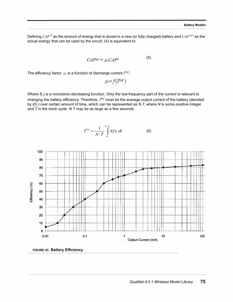
Battery Models
Defining CAP 0 as the amount of energy that is stored in a new (or fully charged) battery and CAP act as the actual energy that can be used by the circuit, (4) is equivalent to:
The efficiency factor is a function of discharge current Ibat:
Where f(.) is a monotonic-decreasing function. Only the low-frequency part of the current is relevant to
changing the battery efficiency. Therefore, Ibat must be the average output current of the battery (denoted by i(t) ) over certain amount of time, which can be represented as N.T, where N is some positive integer and T is the clock cycle. N.T may be as large as a few seconds.
FIGURE 43. Battery Efficiency
(5)
(5)
?C
0
1 ( )N T
batI i t dtN T
QualNet 4.5.1 Wireless Model Library 75
Battery Models
The actual capacity of the battery decreases when the discharge current increases. With discharge current ratio, we estimate battery efficiency using battery efficiency plot such as the one shown in
Figure 43.The Y-axis is efficiency or utilization where the X-axis is the output current of battery, Ibat.
Given the battery capacity model described above, battery estimation is performed as follows. First, the designer characterizes the battery with its rated capacity, the time constant, and the table of points describing the discharge plot similar to the one shown in Figure 43. During each simulation cycle (i.e., N.T) discharge current ratio is computed from the rated battery current. Efficiency is calculated using linear interpolation between the points from the discharge plot. Lower efficiency means that less battery energy remains and thus the battery lifetime is proportionally lower. For example, if battery efficiency is 60% and its rated capacity is 100 mAhr at 1 V, then the battery would be drained in 12 min at average DC-DC current of 300 mA. With efficiency of 100% the battery would last 1 h.
Model 3: Linear Model
This model is a simple linear model which is based on the coulomb counting technique. The coulomb counting technique accumulates the dissipated coulombs from the beginning of the discharge cycle and estimates the remaining capacity based on the difference between the accumulated value and a pre-recorded full-charge capacity. This method can lose some of its accuracy under variable load condition because it ignores the non-linear discharge effect during the coulomb counting process.
The battery is discharged linearly as a function of discharge current load.
Implemented Features
• Implementation of a model for accurate estimation of service life of a battery. This model captures the following contributing factors:
• Battery rate capacity effect: the model which precisely estimates non-linearity effect of rated capacity versus discharge current load.
• Charge recovery effect: the model takes into account the actual phenomenon that battery charge increases when no discharge current load is drawn from the battery for a given period of time.
• Implementation of a model for fairly good prediction of remaining residual life of the battery. The model captures non-linearity of rated capacity versus discharge current load (i.e. Battery rate capacity effect) by introducing utilization function.
• Implementation of a simple linear model based on the Columbus Count method. In this method the battery is discharged linearly over its service life and the rate of discharge at any time is the current which is drawn from battery.
• Battery charge level monitoring: The state of charge of the charge of the batteries attached to a battery-operated node is periodically checked and if the battery is out of charge the node is shut down (currently inserting permanent faults on all network interfaces attached to the node.)
• User configurable battery type: the model developed in the simulator is a generic and parametric model. For the model specification the input parameters must be configured initially for a given battery-type from a battery manufacturer.
• Model 1: The parameter specification and estimation from a battery data sheet was describe earlier in 4.1.Additionly we have precomputed and stored parameters and specifications for several types of batteries including DURACELL(AA and AAA) and ITSY. Therefore, for DURACELL (AA and AAA) and ITSY battery types the specification can be loaded from battery library.
76 QualNet 4.5.1 Wireless Model Library
Battery Models
• Model 2: A lookup table of which specifies Efficiency v.s. output current of battery (in mA) is computed from data sheet of any given battery. We have computed and stored the specifications for several types of batteries including DURACELL (AA and AAA) and PANASONIC. Therefore, for DURACELL (AA and AAA) and PANASONIC battery types the specification can be loaded from battery library.
Assumptions
The following assumptions are made in the implementation of the battery models:
• The output voltage of the battery is considered to be constant during the operation of the battery. Note that in data sheet of a battery the rated capacity versus load has different plots for different output voltages of a battery. Furthermore, note that output voltage of a battery decreases as depth of discharge (ratio of remaining charge to full charge) increases. Fore more accurate modeling, it’s suggested to derive the model parameters from the capacity-load curve measured at average output voltage during service life of the battery.
• The effects of temperature and cycle-aging have not been captured in any of the model which has been currently implemented in the simulator.
• DC-DC model which estimates energy or power lost in DC-DC converter. The converter adjusts output voltage for different components (i.e. to enable different wireless radio interfaces to operate at different voltages.)
QualNet 4.5.1 Wireless Model Library 77
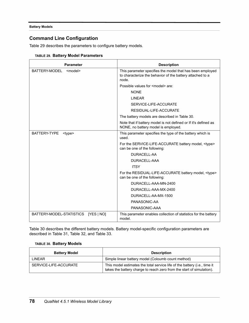
Battery Models
Command Line Configuration
Table 29 describes the parameters to configure battery models.
Table 30 describes the different battery models. Battery model-specific configuration parameters are described in Table 31, Table 32, and Table 33.
TABLE 29. Battery Model Parameters
Parameter Description
BATTERY-MODEL <model> This parameter specifies the model that has been employed to characterize the behavior of the battery attached to a node.
Possible values for <model> are:
NONE
LINEAR
SERVICE-LIFE-ACCURATE
RESIDUAL-LIFE-ACCURATE
The battery models are described in Table 30.
Note that if battery model is not defined or If it's defined as NONE, no battery model is employed.
BATTERY-TYPE <type> This parameter specifies the type of the battery which is used.
For the SERVICE-LIFE-ACCURATE battery model, <type> can be one of the following:
DURACELL-AA
DURACELL-AAA
ITSY
For the RESIDUAL-LIFE-ACCURATE battery model, <type> can be one of the following:
DURACELL-AAA-MN-2400
DURACELL-AAA-MX-2400
DURACELL-AA-MX-1500
PANASONIC-AA
PANASONIC-AAA
BATTERY-MODEL-STATISTICS [YES | NO] This parameter enables collection of statistics for the battery model.
TABLE 30. Battery Models
Battery Model Description
LINEAR Simple linear battery model (Coloumb count method)
SERVICE-LIFE-ACCURATE This model estimates the total service life of the battery (i.e., time it takes the battery charge to reach zero from the start of simulation).
78 QualNet 4.5.1 Wireless Model Library
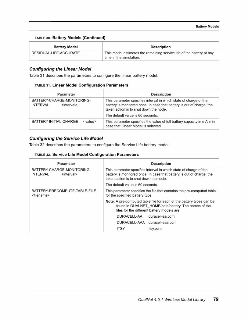
Battery Models
Configuring the Linear Model
Table 31 describes the parameters to configure the linear battery model.
Configuring the Service Life ModelTable 32 describes the parameters to configure the Service Life battery model.
RESIDUAL-LIFE-ACCURATE This model estimates the remaining service life of the battery at any time in the simulation.
TABLE 31. Linear Model Configuration Parameters
Parameter Description
BATTERY-CHARGE-MONITORING-INTERVAL <interval>
This parameter specifies interval in which state of charge of the battery is monitored once. In case that battery is out of charge, the taken action is to shut down the node.
The default value is 60 seconds.
BATTERY-INITIAL-CHARGE <value> This parameter specifies the value of full battery capacity in mAhr in case that Linear Model is selected
TABLE 32. Service Life Model Configuration Parameters
Parameter Description
BATTERY-CHARGE-MONITORING-INTERVAL <interval>
This parameter specifies interval in which state of charge of the battery is monitored once. In case that battery is out of charge, the taken action is to shut down the node.
The default value is 60 seconds.
BATTERY-PRECOMPUTE-TABLE-FILE <filename>
This parameter specifies the file that contains the pre-computed table for the specified battery type.
Note: A pre-computed table file for each of the battery types can be found in QUALNET_HOME/data/battery. The names of the files for the different battery models are:
DURACELL-AA : duracell-aa.pcml
DURACELL-AAA : duracell-aaa.pcm
ITSY : itsy.pcm
TABLE 30. Battery Models (Continued)
Battery Model Description
QualNet 4.5.1 Wireless Model Library 79
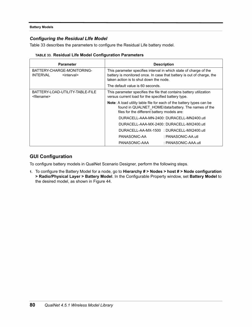
Battery Models
Configuring the Residual LIfe Model
Table 33 describes the parameters to configure the Residual Life battery model.
GUI Configuration
To configure battery models in QualNet Scenario Designer, perform the following steps.
1. To configure the Battery Model for a node, go to Hierarchy # > Nodes > host # > Node configuration > Radio/Physical Layer > Battery Model. In the Configurable Property window, set Battery Model to the desired model, as shown in Figure 44.
TABLE 33. Residual Life Model Configuration Parameters
Parameter Description
BATTERY-CHARGE-MONITORING-INTERVAL <interval>
This parameter specifies interval in which state of charge of the battery is monitored once. In case that battery is out of charge, the taken action is to shut down the node.
The default value is 60 seconds.
BATTERY-LOAD-UTILITY-TABLE-FILE <filename>
This parameter specifies the file that contains battery utilization versus current load for the specified battery type.
Note: A load utility table file for each of the battery types can be found in QUALNET_HOME/data/battery. The names of the files for the different battery models are:
DURACELL-AAA-MN-2400: DURACELL-MN2400.utl
DURACELL-AAA-MX-2400: DURACELL-MX2400.utl
DURACELL-AA-MX-1500 : DURACELL-MX2400.utl
PANASONIC-AA : PANASONIC-AA.utl
PANASONIC-AAA : PANASONIC-AAA.utl
80 QualNet 4.5.1 Wireless Model Library
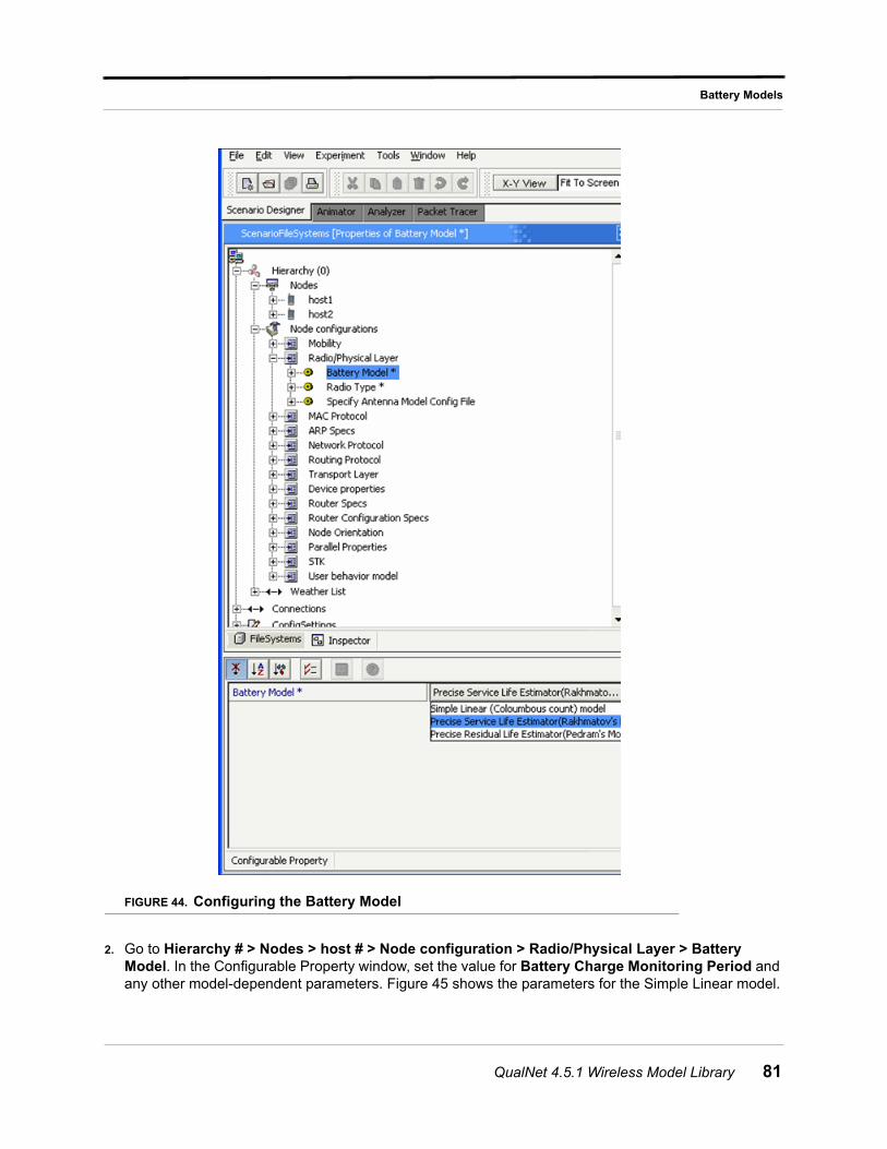
Battery Models
FIGURE 44. Configuring the Battery Model
2. Go to Hierarchy # > Nodes > host # > Node configuration > Radio/Physical Layer > Battery Model. In the Configurable Property window, set the value for Battery Charge Monitoring Period and any other model-dependent parameters. Figure 45 shows the parameters for the Simple Linear model.
QualNet 4.5.1 Wireless Model Library 81
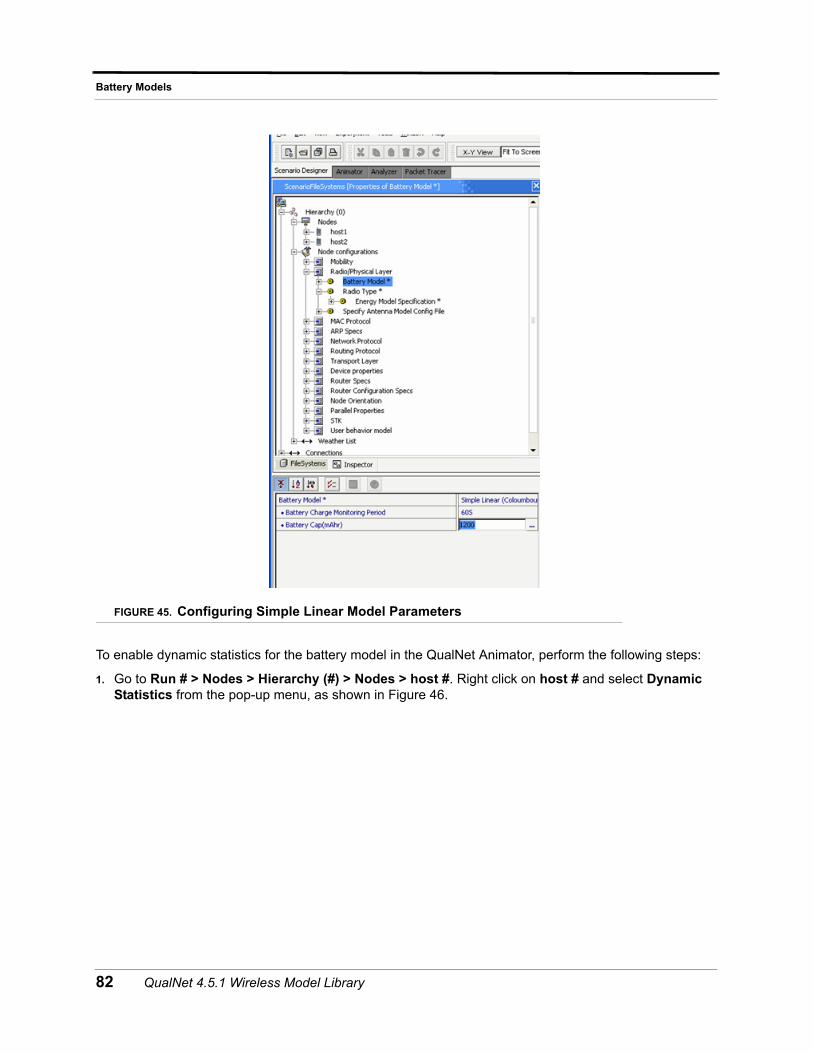
Battery Models
FIGURE 45. Configuring Simple Linear Model Parameters
To enable dynamic statistics for the battery model in the QualNet Animator, perform the following steps:
1. Go to Run # > Nodes > Hierarchy (#) > Nodes > host #. Right click on host # and select Dynamic Statistics from the pop-up menu, as shown in Figure 46.
82 QualNet 4.5.1 Wireless Model Library
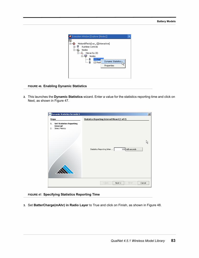
Battery Models
FIGURE 46. Enabling Dynamic Statistics
2. This launches the Dynamic Statistics wizard. Enter a value for the statistics reporting time and click on Next, as shown in Figure 47.
FIGURE 47. Specifying Statistics Reporting Time
3. Set BatterCharge(mAhr) in Radio Layer to True and click on Finish, as shown in Figure 48.
QualNet 4.5.1 Wireless Model Library 83
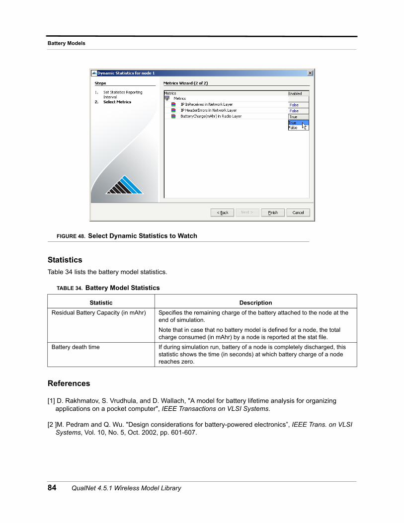
Battery Models
FIGURE 48. Select Dynamic Statistics to Watch
Statistics
Table 34 lists the battery model statistics.
References
[1] D. Rakhmatov, S. Vrudhula, and D. Wallach, "A model for battery lifetime analysis for organizing applications on a pocket computer", IEEE Transactions on VLSI Systems.
[2 ]M. Pedram and Q. Wu. "Design considerations for battery-powered electronics”, IEEE Trans. on VLSI Systems, Vol. 10, No. 5, Oct. 2002, pp. 601-607.
TABLE 34. Battery Model Statistics
Statistic Description
Residual Battery Capacity (in mAhr) Specifies the remaining charge of the battery attached to the node at the end of simulation.
Note that in case that no battery model is defined for a node, the total charge consumed (in mAhr) by a node is reported at the stat file.
Battery death time If during simulation run, battery of a node is completely discharged, this statistic shows the time (in seconds) at which battery charge of a node reaches zero.
84 QualNet 4.5.1 Wireless Model Library
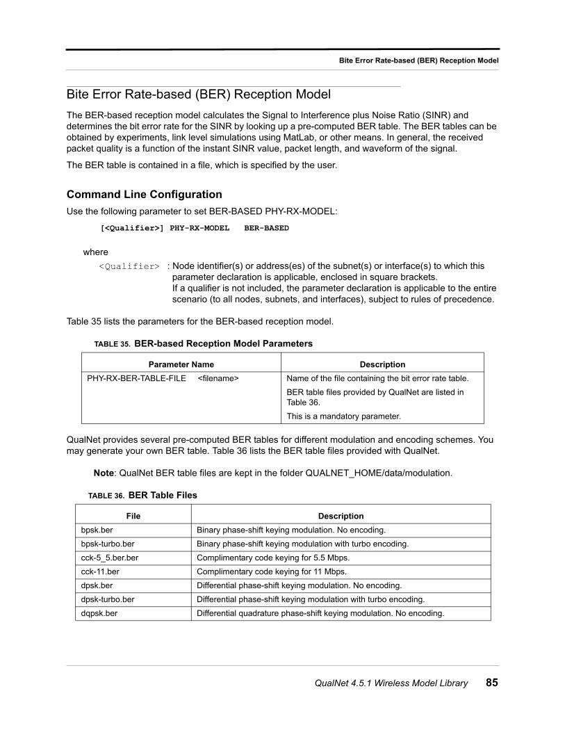
Bite Error Rate-based (BER) Reception Model
Bite Error Rate-based (BER) Reception Model
The BER-based reception model calculates the Signal to Interference plus Noise Ratio (SINR) and determines the bit error rate for the SINR by looking up a pre-computed BER table. The BER tables can be obtained by experiments, link level simulations using MatLab, or other means. In general, the received packet quality is a function of the instant SINR value, packet length, and waveform of the signal.
The BER table is contained in a file, which is specified by the user.
Command Line Configuration
Use the following parameter to set BER-BASED PHY-RX-MODEL:
[<Qualifier>] PHY-RX-MODEL BER-BASED
where
<Qualifier> : Node identifier(s) or address(es) of the subnet(s) or interface(s) to which this parameter declaration is applicable, enclosed in square brackets. If a qualifier is not included, the parameter declaration is applicable to the entire scenario (to all nodes, subnets, and interfaces), subject to rules of precedence.
Table 35 lists the parameters for the BER-based reception model.
QualNet provides several pre-computed BER tables for different modulation and encoding schemes. You may generate your own BER table. Table 36 lists the BER table files provided with QualNet.
Note: QualNet BER table files are kept in the folder QUALNET_HOME/data/modulation.
TABLE 35. BER-based Reception Model Parameters
Parameter Name Description
PHY-RX-BER-TABLE-FILE <filename> Name of the file containing the bit error rate table.
BER table files provided by QualNet are listed in Table 36.
This is a mandatory parameter.
TABLE 36. BER Table Files
File Description
bpsk.ber Binary phase-shift keying modulation. No encoding.
bpsk-turbo.ber Binary phase-shift keying modulation with turbo encoding.
cck-5_5.ber.ber Complimentary code keying for 5.5 Mbps.
cck-11.ber Complimentary code keying for 11 Mbps.
dpsk.ber Differential phase-shift keying modulation. No encoding.
dpsk-turbo.ber Differential phase-shift keying modulation with turbo encoding.
dqpsk.ber Differential quadrature phase-shift keying modulation. No encoding.
QualNet 4.5.1 Wireless Model Library 85
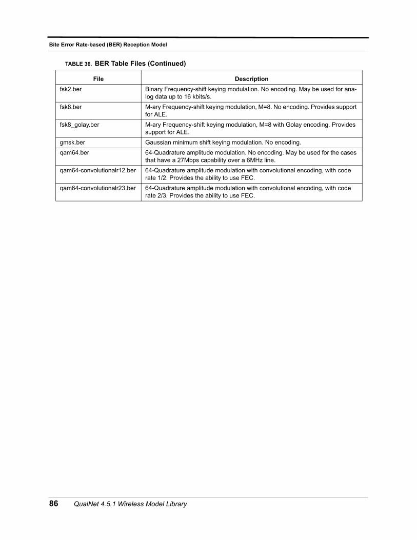
Bite Error Rate-based (BER) Reception Model
fsk2.ber Binary Frequency-shift keying modulation. No encoding. May be used for ana-log data up to 16 kbits/s.
fsk8.ber M-ary Frequency-shift keying modulation, M=8. No encoding. Provides support for ALE.
fsk8_golay.ber M-ary Frequency-shift keying modulation, M=8 with Golay encoding. Provides support for ALE.
gmsk.ber Gaussian minimum shift keying modulation. No encoding.
qam64.ber 64-Quadrature amplitude modulation. No encoding. May be used for the cases that have a 27Mbps capability over a 6MHz line.
qam64-convolutionalr12.ber 64-Quadrature amplitude modulation with convolutional encoding, with code rate 1/2. Provides the ability to use FEC.
qam64-convolutionalr23.ber 64-Quadrature amplitude modulation with convolutional encoding, with code rate 2/3. Provides the ability to use FEC.
TABLE 36. BER Table Files (Continued)
File Description
86 QualNet 4.5.1 Wireless Model Library
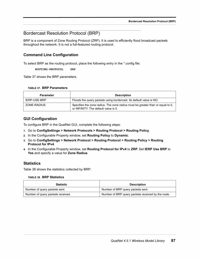
Bordercast Resolution Protocol (BRP)
Bordercast Resolution Protocol (BRP)
BRP is a component of Zone Routing Protocol (ZRP). It is used to efficiently flood broadcast packets throughout the network. It is not a full-featured routing protocol.
Command Line Configuration
To select BRP as the routing protocol, place the following entry in the *.config file:
ROUTING-PROTOCOL ZRP
Table 37 shows the BRP parameters.
GUI Configuration
To configure BRP in the QualNet GUI, complete the following steps:
1. Go to ConfigSettings > Network Protocols > Routing Protocol > Routing Policy.
2. In the Configurable Property window, set Routing Policy to Dynamic.
3. Go to ConfigSettings > Network Protocol > Routing Protocol > Routing Policy > Routing Protocol for IPv4.
4. In the Configurable Property window, set Routing Protocol for IPv4 to ZRP. Set IERP Use BRP to Yes and specify a value for Zone Radius.
Statistics
Table 38 shows the statistics collected by BRP:
TABLE 37. BRP Parameters
Parameter Description
IERP-USE-BRP Floods the query packets using bordercast. Its default value is NO.
ZONE-RADIUS Specifies the zone radius. The zone radius must be greater than or equal to 0, or INFINITY. The default value is 0.
TABLE 38. BRP Statistics
Statistic Description
Number of query packets sent. Number of BRP query packets sent.
Number of query packets received. Number of BRP query packets received by the node.
QualNet 4.5.1 Wireless Model Library 87
Cartesian Terrain Format
Cartesian Terrain Format
QualNet’s Cartesian terrain format is intended to provide terrain data for small areas specified in Cartesian coordinates.
Command Line Configuration
To select this format for terrain data, set the following parameter in the scenario configuration (.config) file:
TERRAIN-DATA-TYPE CARTESIAN
The parameters for specifying the name of the data file to be used when this format is selected are described in Table 39.
Format of the Cartesian Data File
The Cartesian data file is essentially an X by Y grid of elevations, specified in meters.
The first line in the Cartesian data file has the following format:
<Num-X-data-points> <Num-Y-data-points> <Spacing>
where
<Num-X-data-points> : Number of data points in the X direction.
<Num-Y-data-points> : Number of data points in the Y direction.
<Spacing> : Spacing between data points, in meters.
The first line is followed by <Num-Y-data-points> lines, one for each Y-value. Each line has <Num-X-data-points> entries, one for each X-value, and indicates the elevation at that position, in meters.
Note: The lines in the file are in increasing order of Y-value and entries on a line are in increasing order of X-value. Thus, the first entry on the second line of the file is the elevation at the origin and the last entry on the last line is the elevation at the upper-right corner of the terrain (or the location closest to it that can be specified with the chosen spacing).
GUI Configuration
To specify terrain data in Cartesian Terrain format, do the following:
1. Go to ConfigSettings > General > Terrain > Terrain Data Format.
TABLE 39. Cartesian Data File Parameters
Parameter Name Description
CARTESIAN-FILENAME <filename> Specifies the name of the file that contains Cartesian terrain data.
The format of this file is described below.
This parameter is required when TERRAIN-DATA-TYPE is set to Cartesian.
88 QualNet 4.5.1 Wireless Model Library

Cartesian Terrain Format
2. In the Configurable Property window, set Terrain Data Format to CARTESIAN.
3. In the Configurable Property window, set CARTESIAN File to the name of the terrain data file.
QualNet 4.5.1 Wireless Model Library 89
Constant Shadowing Model
Constant Shadowing Model
A shadowing model is used to represent the signal attenuation caused by obstructions along the propagation path. The constant shadowing model is suitable for the scenarios without mobility where the obstructions along the propagation paths remain unchanged.
Command Line Configuration
To select this model, set the parameter PROPAGATION-SHADOWING-MODEL in the configuration file as follows:
PROPAGATION-SHADOWING-MODEL[<Index>] CONSTANT
where
<Index> : Index of channel to which this parameter declaration is applicable, enclosed in square brackets. This should be in the range 0 to n -1, where n is the number of channels.
The instance specification is optional. If an instance is not included, then the parameter declaration is applicable to all channels.
Table 40 lists the parameters for the constant shadowing model.
Statistics
There are no statistics collected by the Constant Shadowing model.
TABLE 40. Constant Shadowing Parameters
Parameter Name Description
PROPAGATION-SHADOWING-MEAN <value>
Specifies propagation shadowing mean (most likely shadowing value for the propagation environment).
The more the number of obstructions along the propagation path, the higher this value should be.
The default value is 4.0 dB.
90 QualNet 4.5.1 Wireless Model Library
Carrier Sense Multiple Access (CSMA) MAC Protocol
Carrier Sense Multiple Access (CSMA) MAC Protocol
Carrier Sense Multiple Access is a generic carrier-sensing protocol. When a radio wishes to send data, it senses the channel. If the channel is busy, it backs off for a random time period before sensing the channel again. If the channel is free, the radio transmits the packet.
Command Line Configuration
To select CSMA as the MAC protocol, place the following entry in the scenario configuration (.config) file:
MAC-PROTOCOL CSMA
Note: CSMA does not have any other configuration parameters.
Statistics
Table 41 shows the statistics collected by the CSMA model.
TABLE 41. CSMA Statistics Collected
Statistics Description
Packets from network Packets received from Network Layer Protocol, i.e., IP
Packets lost to buffer overflow Packets dropped at the MAC layer due to buffer overflow
Unicast packets sent to channel Packets with a specific destination address transmitted on the channel
Broadcast packets sent to channel Packets broadcast to all radios within transmission range
Unicast packets received from channel Packets destined for this specific radio and successfully received
Broadcast packets received from channel Packets destined for all radios and successfully received by this radio
QualNet 4.5.1 Wireless Model Library 91
Digital Elevation Model (DEM) Terrain Format
Digital Elevation Model (DEM) Terrain Format
Digital Elevation Model (DEM) is a is a standard format for representing terrain elevation data. It is a digital representation of ground surface topography or terrain format.
DEM files are produced by the USGS. QualNet supports only the 1 degree files with elevation points in a grid at approximately 100 meters spacing.
Command Line Configuration
To specify DEM as the terrain data type, include the following parameter in the scenario configuration (.config) file:
TERRAIN-DATA-TYPE DEM
Table 42 lists the DEM configuration parameters.
GUI Configuration
To specify terrain data in DEM format, do the following:
1. Go to ConfigSettings > General > Terrain > Terrain Data Format. In the Configurable Property window, set Terrain Data Format to USGS DEM.
2. Go to ConfigSettings > General > Terrain > Terrain Data Format > DEM File. In the Configurable Property window, set DEM File to the name of the terrain data file.
3. If there are more than one DEM files, then go to ConfigSettings > General > Terrain > Terrain Data Format > DEM File. Right click on DEM File and select Add another. This creates another entry for DEM File with an index. Select a DEM File in the Inspector and specify it’s name in the Configurable Property window.
References
More information on DEM is available at the following websites:
• The government standard is currently available at:
http://rockyweb.cr.usgs.gov/nmpstds/demstds.html
TABLE 42. DEM Parameters
Parameter Description
DEM-FILENAME[n] <filename>
where n = 0, 1, 2, ...
Specifies the relative or absolute path and filename for the DEM data file for the selected terrain.
Include as many instances of this parameter as the number of DEM files. if there is only one DEM file, the index can be omitted.
The relative path is relative to QUALNET_HOME.
92 QualNet 4.5.1 Wireless Model Library
Digital Elevation Model (DEM) Terrain Format
• Data Sets Information is available at:
http://eros.usgs.gov/geodata/
• Legacy/"native" format 1x1 degree information is available at:
http://edcftp.cr.usgs.gov/pub/data/DEM/250/
QualNet 4.5.1 Wireless Model Library 93
Digital Terrain Elevation (DTED) Terrain Format
Digital Terrain Elevation (DTED) Terrain Format
Digital Terrain Elevation Data (DTED) is a format for representing terrain elevation data. DTED files provides basic quantitative data for systems and application that require terrain elevation, slope, and surface roughness information.
DTED data are available from a variety of sources and in various resolutions. All resolutions contain grids of elevation points. DTED level 0 is spaced at about 1000 meters per data point, DTED level 1 at 100 meters, DTED level 2 at 30 meters, DTED level 3 at 10 meters, DTED level 4 at 3 meters, and DTED level 5 at 1 meter.
QualNet supports use of multi-resolution DTED files (levels 0, 1 and 2).
Memory Usage
The memory consumption of DTED terrain files depends on the type of file used and on the size of the file.
• DTED Level 0 files use about 25-50 KB.
• DTED Level 1 files use about 2.5-3.5 MB.
In a cluster environment every processor loads every DTED file in the simulation. So if a scenario uses 100 DTED Level 1 files of size 2.8 MB each and the scenario is run on a 16 processor cluster, the memory used will be 280 MB per processor, or about 4.5 GB total.
Note: The maximum number of DTED files that can be loaded simultaneously is 100. This number can be modified if needed. Contact [email protected] for more information.
Command Line Configuration
To specify DTED as the terrain data type, include the following parameter in the scenario configuration (.config) file:
TERRAIN-DATA-TYPE DTED
Table 43 lists the DTED configuration parameters.
TABLE 43. DTED Parameters
Parameter Description
DTED-FILENAME[n] <filename>
where n = 0, 1, 2, ...
Specifies the relative or absolute path and filename for the DTED data file for the selected terrain.
Include as many instances of this parameter as the number of DTED files. if there is only one DTED file, the index can be omitted.
The relative path is relative to QUALNET_HOME.
94 QualNet 4.5.1 Wireless Model Library
Digital Terrain Elevation (DTED) Terrain Format
GUI Configuration
To specify terrain data in DTED format, do the following:
1. Go to ConfigSettings > General > Terrain > Terrain Data Format. In the Configurable Property window, set Terrain Data Format to DTED.
2. Go to ConfigSettings > General > Terrain > Terrain Data Format > DTED File. In the Configurable Property window, set DTED File to the name of the terrain data file.
3. If there are more than one DTED files, then go to ConfigSettings > General > Terrain > Terrain Data Format > DTED File. Right click on DTED File and select Add another. This creates another entry for DTED File with an index. Select a DTED File in the Inspector and specify it’s name in the Configurable Property window.
Sample Scenario
To create a scenario using a DTED file as the terrain requires access to the DTED files and knowing their terrain dimensions. DTED files are generally distributed in a 1 degree by 1 degree format. Users will need to provide the coordinates of the south-west and north-east corners of the desired terrain.
Scenario DescriptionA sample DTED scenario (dtedtest.scn) is included in the QUALNET_HOME/scenarios/gui directory. The terrain area covered by this scenario has the south-west corner at (12S, 105E) and the north-east corner at (9S, 106E). Three one-degree DTED level 0 files (s10e105.dt0, s11e105.dt0 and s12e105.dt0) are used to provide basic coverage of the entire area. These files are located in the QUALNET_HOME/scenarios/gui/dtedtest directory.
Figure 49 shows the sample DTD scenario in QualNet GUI.
QualNet 4.5.1 Wireless Model Library 95
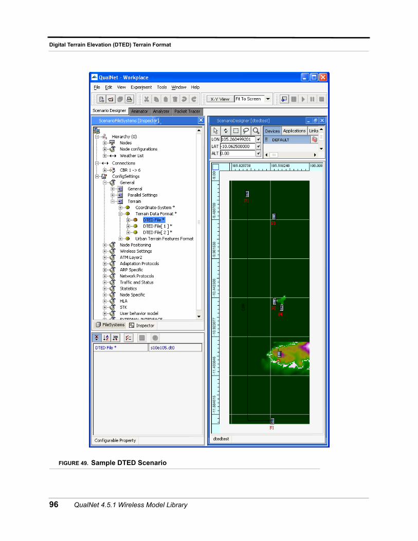
Digital Terrain Elevation (DTED) Terrain Format
FIGURE 49. Sample DTED Scenario
96 QualNet 4.5.1 Wireless Model Library
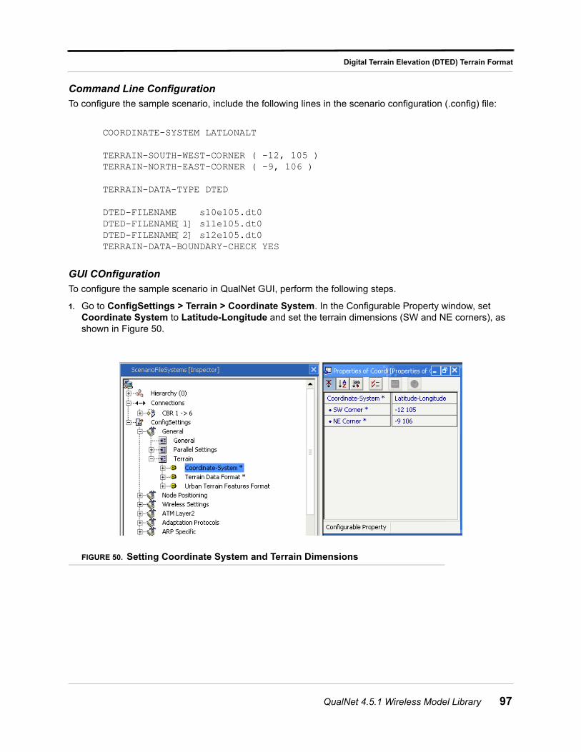
Digital Terrain Elevation (DTED) Terrain Format
Command Line Configuration
To configure the sample scenario, include the following lines in the scenario configuration (.config) file:
COORDINATE-SYSTEM LATLONALT
TERRAIN-SOUTH-WEST-CORNER ( -12, 105 )TERRAIN-NORTH-EAST-CORNER ( -9, 106 )
TERRAIN-DATA-TYPE DTED
DTED-FILENAME s10e105.dt0DTED-FILENAME[1] s11e105.dt0DTED-FILENAME[2] s12e105.dt0TERRAIN-DATA-BOUNDARY-CHECK YES
GUI COnfiguration
To configure the sample scenario in QualNet GUI, perform the following steps.
1. Go to ConfigSettings > Terrain > Coordinate System. In the Configurable Property window, set Coordinate System to Latitude-Longitude and set the terrain dimensions (SW and NE corners), as shown in Figure 50.
FIGURE 50. Setting Coordinate System and Terrain Dimensions
QualNet 4.5.1 Wireless Model Library 97
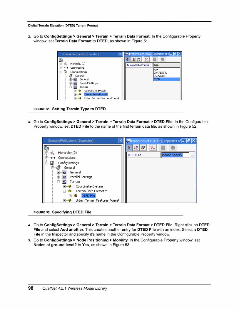
Digital Terrain Elevation (DTED) Terrain Format
2. Go to ConfigSettings > General > Terrain > Terrain Data Format. In the Configurable Property window, set Terrain Data Format to DTED, as shown in Figure 51.
FIGURE 51. Setting Terrain Type to DTED
3. Go to ConfigSettings > General > Terrain > Terrain Data Format > DTED File. In the Configurable Property window, set DTED File to the name of the first terrain data file, as shown in Figure 52.
FIGURE 52. Specifying DTED File
4. Go to ConfigSettings > General > Terrain > Terrain Data Format > DTED File. Right click on DTED File and select Add another. This creates another entry for DTED File with an index. Select a DTED File in the Inspector and specify it’s name in the Configurable Property window.
5. Go to ConfigSettings > Node Positioning > Mobility. In the Configurable Property window, set Nodes at ground level? to Yes, as shown in Figure 53.
98 QualNet 4.5.1 Wireless Model Library
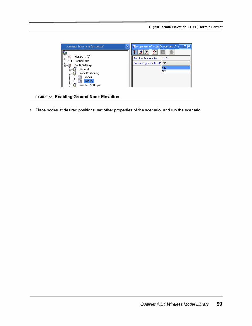
Digital Terrain Elevation (DTED) Terrain Format
FIGURE 53. Enabling Ground Node Elevation
6. Place nodes at desired positions, set other properties of the scenario, and run the scenario.
QualNet 4.5.1 Wireless Model Library 99
Dynamic MANET On-demand (DYMO) Routing Protocol
Dynamic MANET On-demand (DYMO) Routing Protocol
The DYnamic MANET On-demand (DYMO) routing protocol is a unicast reactive routing protocol which is intended for used by mobile nodes in wireless multihop networks. DYMO is a reactive routing protocol. In this Routing Message (Control Packet) is generated only when the node receives a data packet and it does not have any routing information. The basic operation of DYMO protocol is route discovery and route management.
During route discovery the Route Request (RREQ) routing message is generated for a target for which it does not have any routing formation. So the originating node floods the RREQ message to find the target node. During flooding each intermediate node records a route to the originating node by maintaining routing table. When the target node receives the RREQ, it responds with a Route Reply (RREP) which is unicast toward the originating node. Each node that receives the RREP records a route to the target node, and forwards the RREP to next hop. When the originating node receives the RREP, routes have been established between the originating node and the target node in both directions. In order to react changes in the network topology nodes maintain their routes and monitor their links. When a packet is received for a route that is no longer available the source of the packet generates Route Error (RERR). This RERR RM notifies other nodes that the current route is broken. Once the source receives the RERR, it re-initiates route discovery if it still has packets to deliver. In order to maintain active route it uses hello message broadcasting scheme. DYMO uses standard MANET packet structure. DYMO uses sequence numbers to avoid loop freedom, so that old routing information will not be propagated further.
Command Line Configuration
To select DYMO as the routing protocol, specify the following parameter(s) in the scenario configuration (.config) file:
• For an IPv4 node, use the following parameter:
ROUTING-PROTOCOL DYMO
• For an IPv6 node, use either of the following parameters:
ROUTING-PROTOCOL DYMO
orROUTING-PROTOCOL-IPv6 DYMO
• For a dual IP-node, use both the following parameter:
ROUTING-PROTOCOL DYMO
andROUTING-PROTOCOL-IPv6 DYMO
100 QualNet 4.5.1 Wireless Model Library
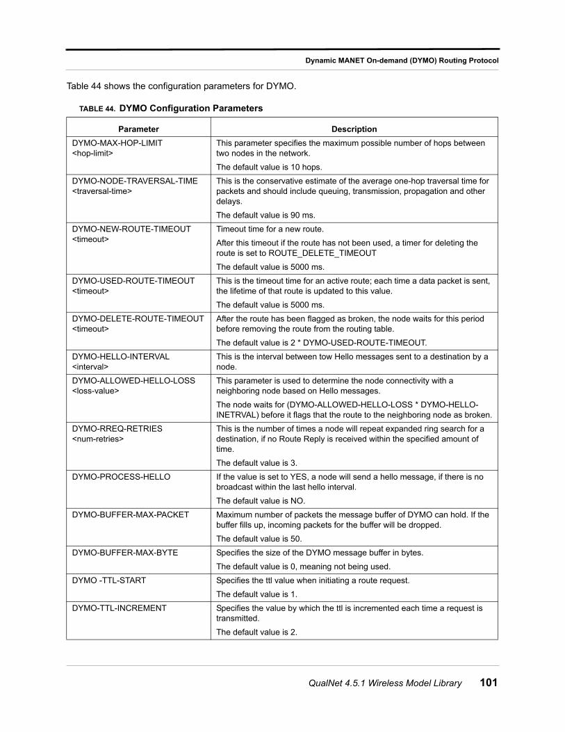
Dynamic MANET On-demand (DYMO) Routing Protocol
Table 44 shows the configuration parameters for DYMO.
TABLE 44. DYMO Configuration Parameters
Parameter Description
DYMO-MAX-HOP-LIMIT <hop-limit>
This parameter specifies the maximum possible number of hops between two nodes in the network.
The default value is 10 hops.
DYMO-NODE-TRAVERSAL-TIME <traversal-time>
This is the conservative estimate of the average one-hop traversal time for packets and should include queuing, transmission, propagation and other delays.
The default value is 90 ms.
DYMO-NEW-ROUTE-TIMEOUT <timeout>
Timeout time for a new route.
After this timeout if the route has not been used, a timer for deleting the route is set to ROUTE_DELETE_TIMEOUT
The default value is 5000 ms.
DYMO-USED-ROUTE-TIMEOUT <timeout>
This is the timeout time for an active route; each time a data packet is sent, the lifetime of that route is updated to this value.
The default value is 5000 ms.
DYMO-DELETE-ROUTE-TIMEOUT <timeout>
After the route has been flagged as broken, the node waits for this period before removing the route from the routing table.
The default value is 2 * DYMO-USED-ROUTE-TIMEOUT.
DYMO-HELLO-INTERVAL <interval>
This is the interval between tow Hello messages sent to a destination by a node.
DYMO-ALLOWED-HELLO-LOSS <loss-value>
This parameter is used to determine the node connectivity with a neighboring node based on Hello messages.
The node waits for (DYMO-ALLOWED-HELLO-LOSS * DYMO-HELLO-INETRVAL) before it flags that the route to the neighboring node as broken.
DYMO-RREQ-RETRIES <num-retries>
This is the number of times a node will repeat expanded ring search for a destination, if no Route Reply is received within the specified amount of time.
The default value is 3.
DYMO-PROCESS-HELLO If the value is set to YES, a node will send a hello message, if there is no broadcast within the last hello interval.
The default value is NO.
DYMO-BUFFER-MAX-PACKET Maximum number of packets the message buffer of DYMO can hold. If the buffer fills up, incoming packets for the buffer will be dropped.
The default value is 50.
DYMO-BUFFER-MAX-BYTE Specifies the size of the DYMO message buffer in bytes.
The default value is 0, meaning not being used.
DYMO -TTL-START Specifies the ttl value when initiating a route request.
The default value is 1.
DYMO-TTL-INCREMENT Specifies the value by which the ttl is incremented each time a request is transmitted.
The default value is 2.
QualNet 4.5.1 Wireless Model Library 101
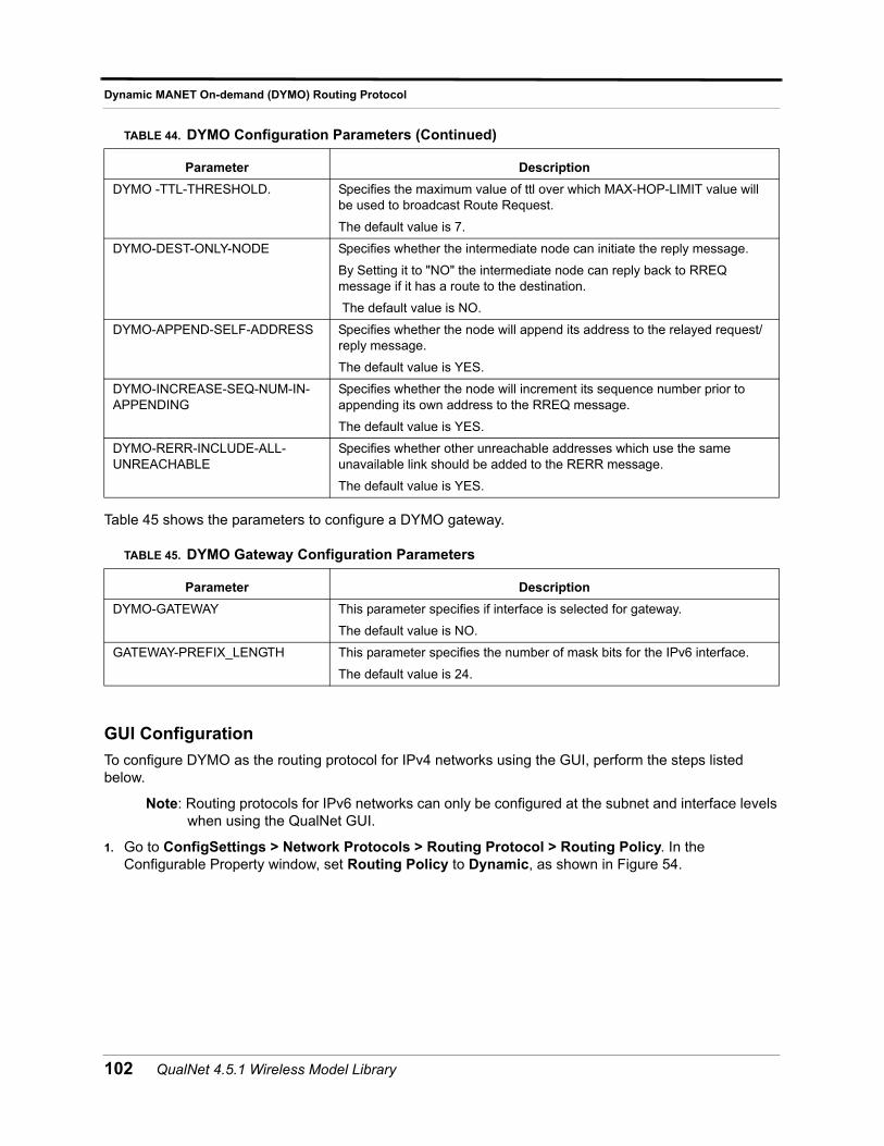
Dynamic MANET On-demand (DYMO) Routing Protocol
Table 45 shows the parameters to configure a DYMO gateway.
GUI Configuration
To configure DYMO as the routing protocol for IPv4 networks using the GUI, perform the steps listed below.
Note: Routing protocols for IPv6 networks can only be configured at the subnet and interface levels when using the QualNet GUI.
1. Go to ConfigSettings > Network Protocols > Routing Protocol > Routing Policy. In the Configurable Property window, set Routing Policy to Dynamic, as shown in Figure 54.
DYMO -TTL-THRESHOLD. Specifies the maximum value of ttl over which MAX-HOP-LIMIT value will be used to broadcast Route Request.
The default value is 7.
DYMO-DEST-ONLY-NODE Specifies whether the intermediate node can initiate the reply message.
By Setting it to "NO" the intermediate node can reply back to RREQ message if it has a route to the destination.
The default value is NO.
DYMO-APPEND-SELF-ADDRESS Specifies whether the node will append its address to the relayed request/reply message.
The default value is YES.
DYMO-INCREASE-SEQ-NUM-IN-APPENDING
Specifies whether the node will increment its sequence number prior to appending its own address to the RREQ message.
The default value is YES.
DYMO-RERR-INCLUDE-ALL-UNREACHABLE
Specifies whether other unreachable addresses which use the same unavailable link should be added to the RERR message.
The default value is YES.
TABLE 45. DYMO Gateway Configuration Parameters
Parameter Description
DYMO-GATEWAY This parameter specifies if interface is selected for gateway.
The default value is NO.
GATEWAY-PREFIX_LENGTH This parameter specifies the number of mask bits for the IPv6 interface.
The default value is 24.
TABLE 44. DYMO Configuration Parameters (Continued)
Parameter Description
102 QualNet 4.5.1 Wireless Model Library
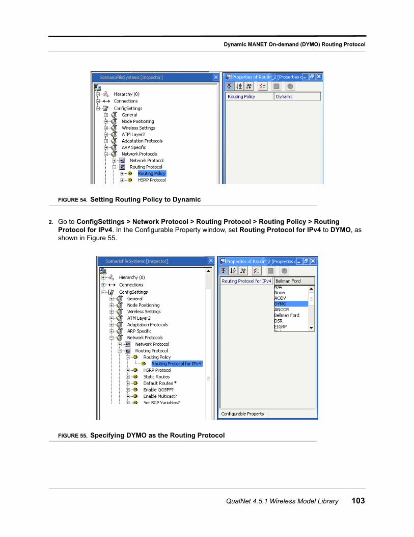
Dynamic MANET On-demand (DYMO) Routing Protocol
FIGURE 54. Setting Routing Policy to Dynamic
2. Go to ConfigSettings > Network Protocol > Routing Protocol > Routing Policy > Routing Protocol for IPv4. In the Configurable Property window, set Routing Protocol for IPv4 to DYMO, as shown in Figure 55.
FIGURE 55. Specifying DYMO as the Routing Protocol
QualNet 4.5.1 Wireless Model Library 103
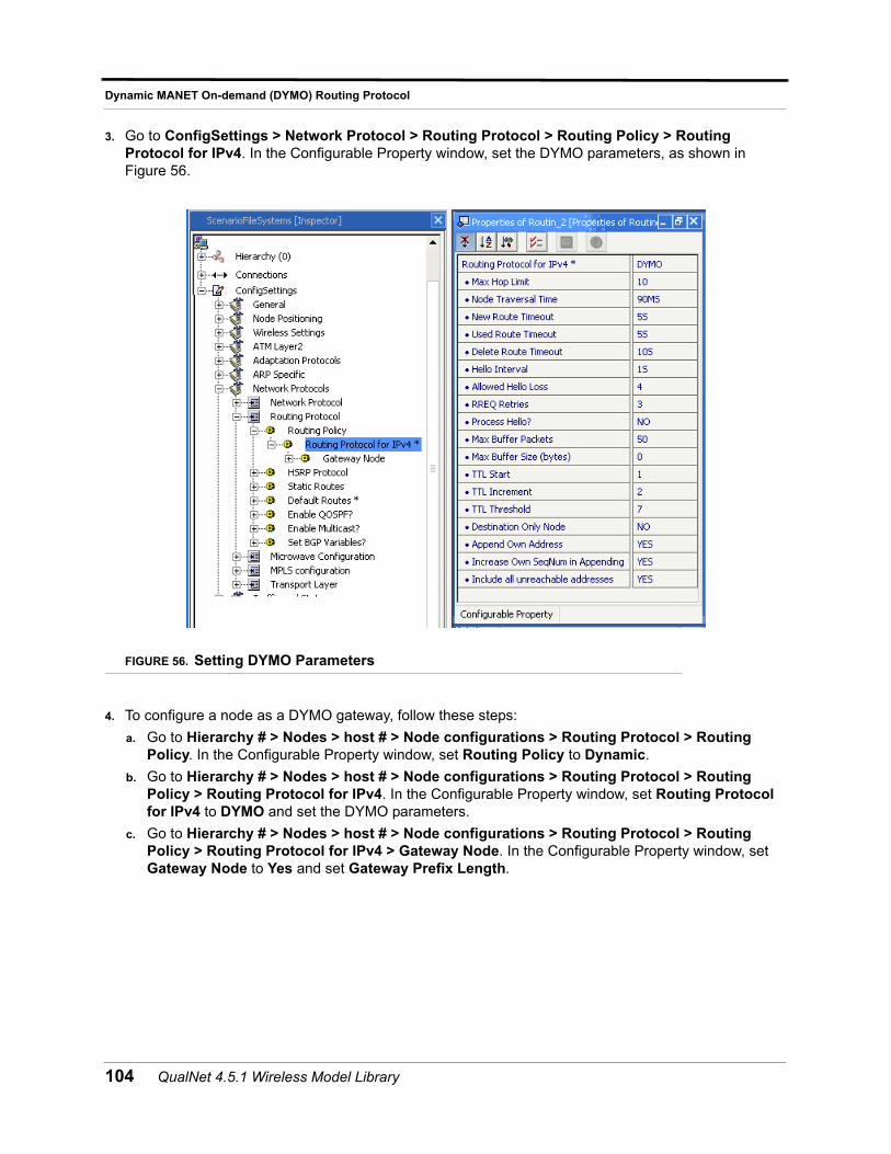
Dynamic MANET On-demand (DYMO) Routing Protocol
3. Go to ConfigSettings > Network Protocol > Routing Protocol > Routing Policy > Routing Protocol for IPv4. In the Configurable Property window, set the DYMO parameters, as shown in Figure 56.
FIGURE 56. Setting DYMO Parameters
4. To configure a node as a DYMO gateway, follow these steps:
a. Go to Hierarchy # > Nodes > host # > Node configurations > Routing Protocol > Routing Policy. In the Configurable Property window, set Routing Policy to Dynamic.
b. Go to Hierarchy # > Nodes > host # > Node configurations > Routing Protocol > Routing Policy > Routing Protocol for IPv4. In the Configurable Property window, set Routing Protocol for IPv4 to DYMO and set the DYMO parameters.
c. Go to Hierarchy # > Nodes > host # > Node configurations > Routing Protocol > Routing Policy > Routing Protocol for IPv4 > Gateway Node. In the Configurable Property window, set Gateway Node to Yes and set Gateway Prefix Length.
104 QualNet 4.5.1 Wireless Model Library
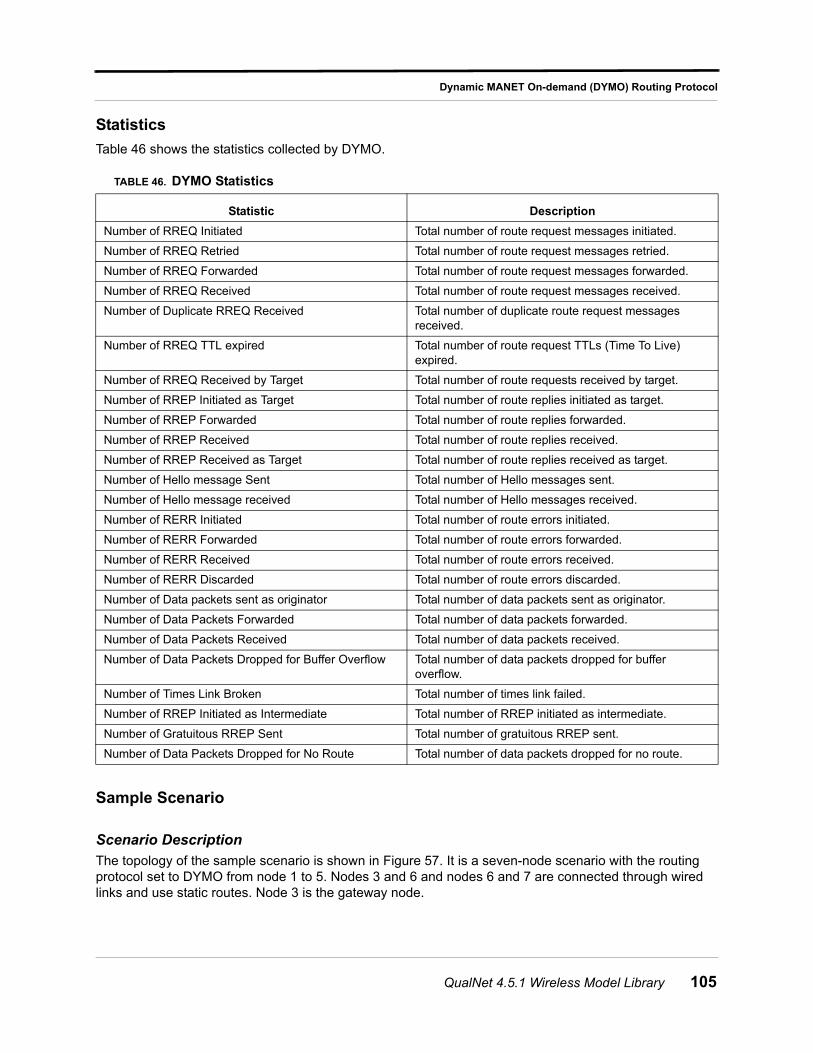
Dynamic MANET On-demand (DYMO) Routing Protocol
Statistics
Table 46 shows the statistics collected by DYMO.
Sample Scenario
Scenario Description
The topology of the sample scenario is shown in Figure 57. It is a seven-node scenario with the routing protocol set to DYMO from node 1 to 5. Nodes 3 and 6 and nodes 6 and 7 are connected through wired links and use static routes. Node 3 is the gateway node.
TABLE 46. DYMO Statistics
Statistic Description
Number of RREQ Initiated Total number of route request messages initiated.
Number of RREQ Retried Total number of route request messages retried.
Number of RREQ Forwarded Total number of route request messages forwarded.
Number of RREQ Received Total number of route request messages received.
Number of Duplicate RREQ Received Total number of duplicate route request messages received.
Number of RREQ TTL expired Total number of route request TTLs (Time To Live) expired.
Number of RREQ Received by Target Total number of route requests received by target.
Number of RREP Initiated as Target Total number of route replies initiated as target.
Number of RREP Forwarded Total number of route replies forwarded.
Number of RREP Received Total number of route replies received.
Number of RREP Received as Target Total number of route replies received as target.
Number of Hello message Sent Total number of Hello messages sent.
Number of Hello message received Total number of Hello messages received.
Number of RERR Initiated Total number of route errors initiated.
Number of RERR Forwarded Total number of route errors forwarded.
Number of RERR Received Total number of route errors received.
Number of RERR Discarded Total number of route errors discarded.
Number of Data packets sent as originator Total number of data packets sent as originator.
Number of Data Packets Forwarded Total number of data packets forwarded.
Number of Data Packets Received Total number of data packets received.
Number of Data Packets Dropped for Buffer Overflow Total number of data packets dropped for buffer overflow.
Number of Times Link Broken Total number of times link failed.
Number of RREP Initiated as Intermediate Total number of RREP initiated as intermediate.
Number of Gratuitous RREP Sent Total number of gratuitous RREP sent.
Number of Data Packets Dropped for No Route Total number of data packets dropped for no route.
QualNet 4.5.1 Wireless Model Library 105
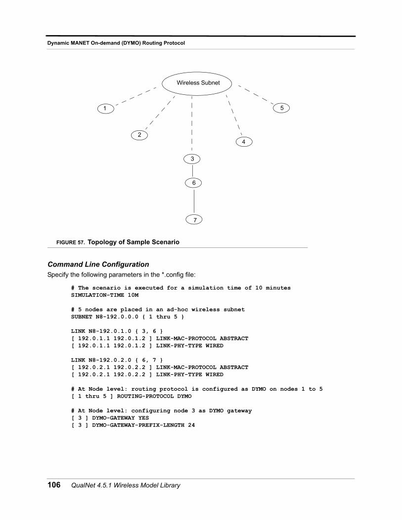
Dynamic MANET On-demand (DYMO) Routing Protocol
FIGURE 57. Topology of Sample Scenario
Command Line Configuration Specify the following parameters in the *.config file:
# The scenario is executed for a simulation time of 10 minutesSIMULATION-TIME 10M
# 5 nodes are placed in an ad-hoc wireless subnetSUBNET N8-192.0.0.0 { 1 thru 5 }
LINK N8-192.0.1.0 { 3, 6 }[ 192.0.1.1 192.0.1.2 ] LINK-MAC-PROTOCOL ABSTRACT[ 192.0.1.1 192.0.1.2 ] LINK-PHY-TYPE WIRED
LINK N8-192.0.2.0 { 6, 7 }[ 192.0.2.1 192.0.2.2 ] LINK-MAC-PROTOCOL ABSTRACT[ 192.0.2.1 192.0.2.2 ] LINK-PHY-TYPE WIRED
# At Node level: routing protocol is configured as DYMO on nodes 1 to 5[ 1 thru 5 ] ROUTING-PROTOCOL DYMO
# At Node level: configuring node 3 as DYMO gateway[ 3 ] DYMO-GATEWAY YES[ 3 ] DYMO-GATEWAY-PREFIX-LENGTH 24
Wireless Subnet
1
2
3
4
5
6
7
106 QualNet 4.5.1 Wireless Model Library
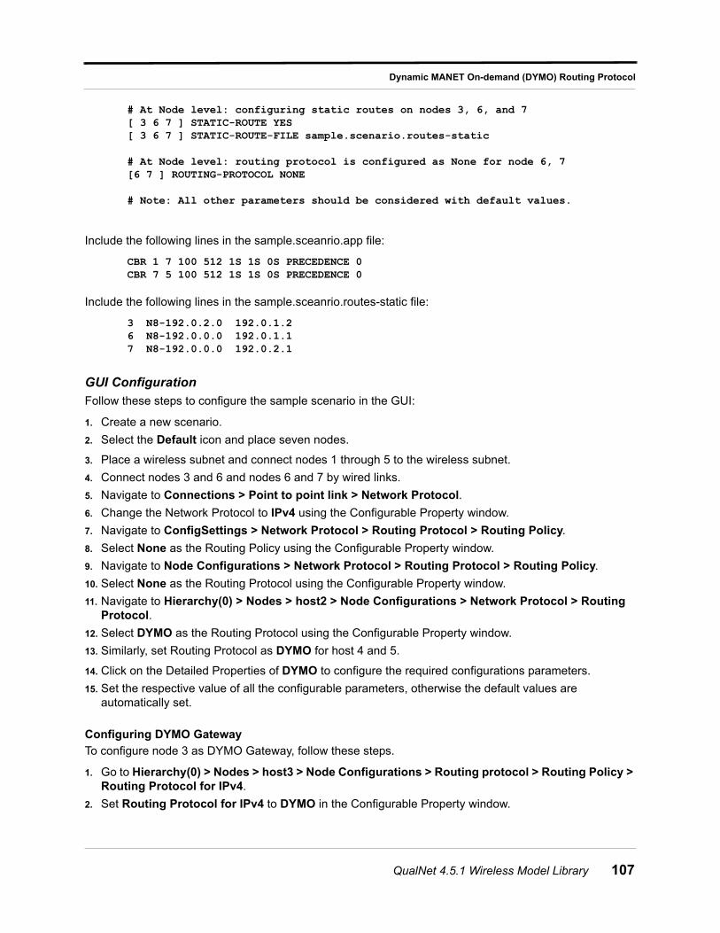
Dynamic MANET On-demand (DYMO) Routing Protocol
# At Node level: configuring static routes on nodes 3, 6, and 7[ 3 6 7 ] STATIC-ROUTE YES[ 3 6 7 ] STATIC-ROUTE-FILE sample.scenario.routes-static
# At Node level: routing protocol is configured as None for node 6, 7[6 7 ] ROUTING-PROTOCOL NONE
# Note: All other parameters should be considered with default values.
Include the following lines in the sample.sceanrio.app file:
CBR 1 7 100 512 1S 1S 0S PRECEDENCE 0CBR 7 5 100 512 1S 1S 0S PRECEDENCE 0
Include the following lines in the sample.sceanrio.routes-static file:
3 N8-192.0.2.0 192.0.1.26 N8-192.0.0.0 192.0.1.17 N8-192.0.0.0 192.0.2.1
GUI Configuration
Follow these steps to configure the sample scenario in the GUI:
1. Create a new scenario.
2. Select the Default icon and place seven nodes.
3. Place a wireless subnet and connect nodes 1 through 5 to the wireless subnet.
4. Connect nodes 3 and 6 and nodes 6 and 7 by wired links.
5. Navigate to Connections > Point to point link > Network Protocol.
6. Change the Network Protocol to IPv4 using the Configurable Property window.
7. Navigate to ConfigSettings > Network Protocol > Routing Protocol > Routing Policy.
8. Select None as the Routing Policy using the Configurable Property window.
9. Navigate to Node Configurations > Network Protocol > Routing Protocol > Routing Policy.
10. Select None as the Routing Protocol using the Configurable Property window.
11. Navigate to Hierarchy(0) > Nodes > host2 > Node Configurations > Network Protocol > Routing Protocol.
12. Select DYMO as the Routing Protocol using the Configurable Property window.
13. Similarly, set Routing Protocol as DYMO for host 4 and 5.
14. Click on the Detailed Properties of DYMO to configure the required configurations parameters.
15. Set the respective value of all the configurable parameters, otherwise the default values are automatically set.
Configuring DYMO Gateway
To configure node 3 as DYMO Gateway, follow these steps.
1. Go to Hierarchy(0) > Nodes > host3 > Node Configurations > Routing protocol > Routing Policy > Routing Protocol for IPv4.
2. Set Routing Protocol for IPv4 to DYMO in the Configurable Property window.
QualNet 4.5.1 Wireless Model Library 107
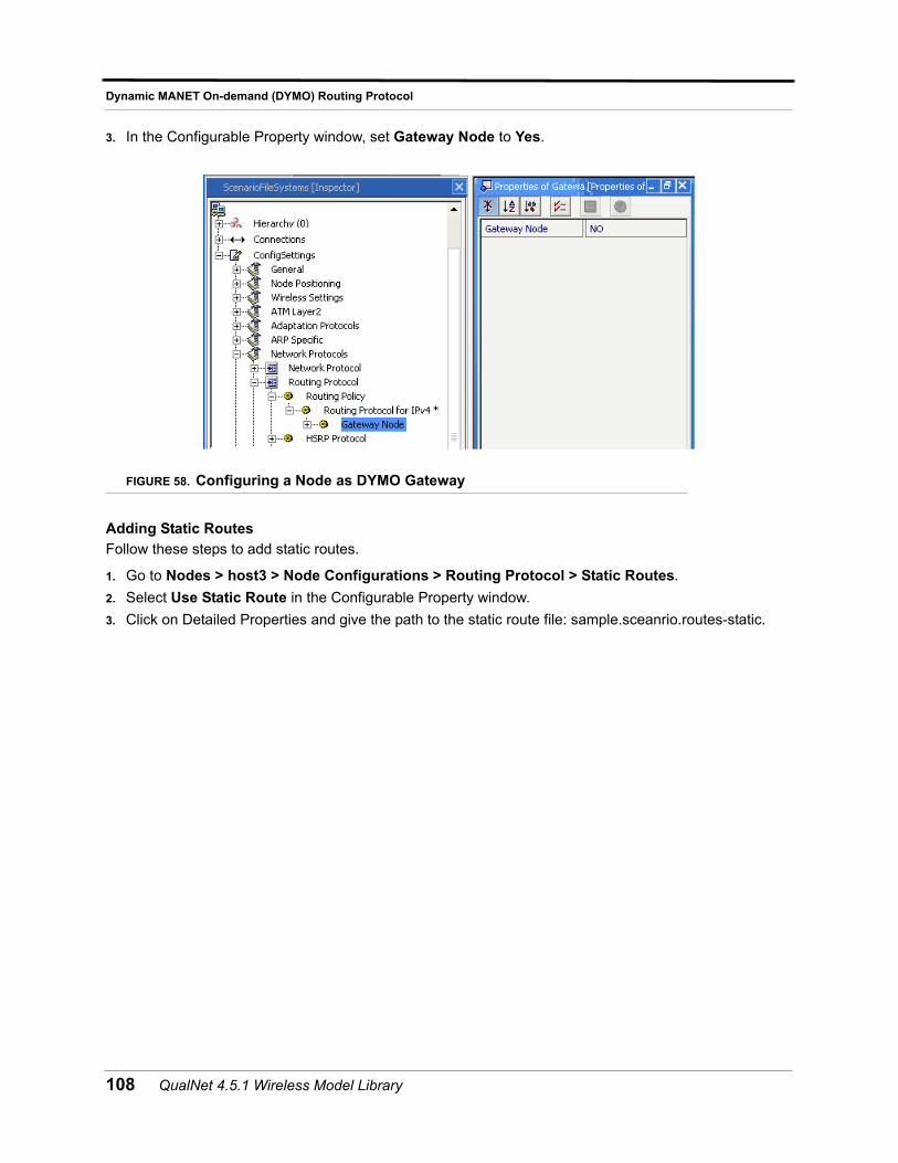
Dynamic MANET On-demand (DYMO) Routing Protocol
3. In the Configurable Property window, set Gateway Node to Yes.
FIGURE 58. Configuring a Node as DYMO Gateway
Adding Static Routes
Follow these steps to add static routes.
1. Go to Nodes > host3 > Node Configurations > Routing Protocol > Static Routes.
2. Select Use Static Route in the Configurable Property window.
3. Click on Detailed Properties and give the path to the static route file: sample.sceanrio.routes-static.
108 QualNet 4.5.1 Wireless Model Library
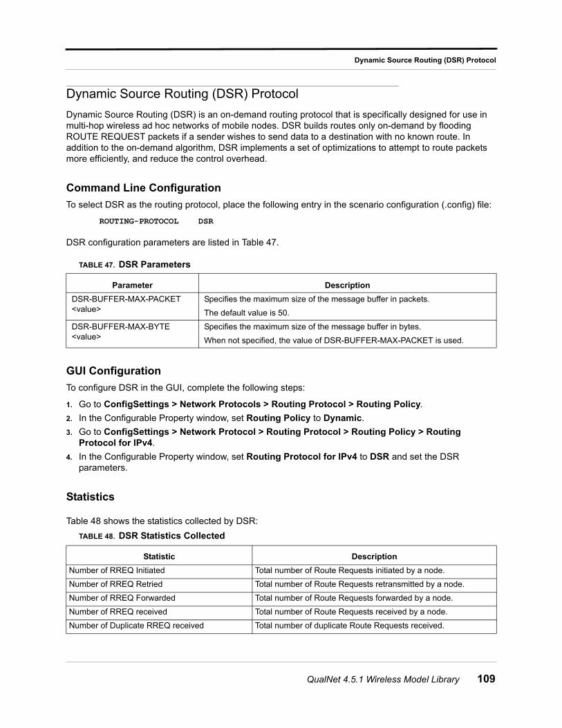
Dynamic Source Routing (DSR) Protocol
Dynamic Source Routing (DSR) Protocol
Dynamic Source Routing (DSR) is an on-demand routing protocol that is specifically designed for use in multi-hop wireless ad hoc networks of mobile nodes. DSR builds routes only on-demand by flooding ROUTE REQUEST packets if a sender wishes to send data to a destination with no known route. In addition to the on-demand algorithm, DSR implements a set of optimizations to attempt to route packets more efficiently, and reduce the control overhead.
Command Line Configuration
To select DSR as the routing protocol, place the following entry in the scenario configuration (.config) file:
ROUTING-PROTOCOL DSR
DSR configuration parameters are listed in Table 47.
GUI Configuration
To configure DSR in the GUI, complete the following steps:
1. Go to ConfigSettings > Network Protocols > Routing Protocol > Routing Policy.
2. In the Configurable Property window, set Routing Policy to Dynamic.
3. Go to ConfigSettings > Network Protocol > Routing Protocol > Routing Policy > Routing Protocol for IPv4.
4. In the Configurable Property window, set Routing Protocol for IPv4 to DSR and set the DSR parameters.
Statistics
Table 48 shows the statistics collected by DSR:
TABLE 47. DSR Parameters
Parameter Description
DSR-BUFFER-MAX-PACKET <value>
Specifies the maximum size of the message buffer in packets.
The default value is 50.
DSR-BUFFER-MAX-BYTE <value>
Specifies the maximum size of the message buffer in bytes.
When not specified, the value of DSR-BUFFER-MAX-PACKET is used.
TABLE 48. DSR Statistics Collected
Statistic Description
Number of RREQ Initiated Total number of Route Requests initiated by a node.
Number of RREQ Retried Total number of Route Requests retransmitted by a node.
Number of RREQ Forwarded Total number of Route Requests forwarded by a node.
Number of RREQ received Total number of Route Requests received by a node.
Number of Duplicate RREQ received Total number of duplicate Route Requests received.
QualNet 4.5.1 Wireless Model Library 109
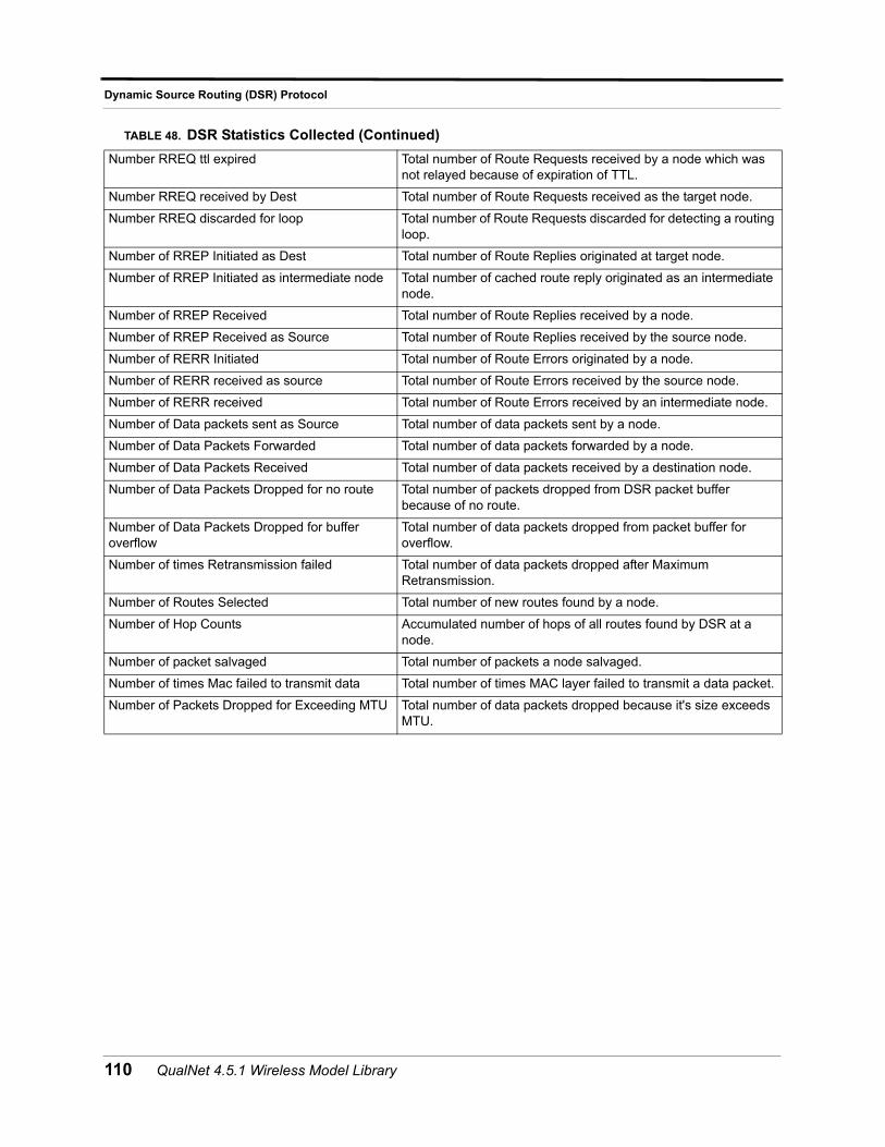
Dynamic Source Routing (DSR) Protocol
Number RREQ ttl expired Total number of Route Requests received by a node which was not relayed because of expiration of TTL.
Number RREQ received by Dest Total number of Route Requests received as the target node.
Number RREQ discarded for loop Total number of Route Requests discarded for detecting a routing loop.
Number of RREP Initiated as Dest Total number of Route Replies originated at target node.
Number of RREP Initiated as intermediate node Total number of cached route reply originated as an intermediate node.
Number of RREP Received Total number of Route Replies received by a node.
Number of RREP Received as Source Total number of Route Replies received by the source node.
Number of RERR Initiated Total number of Route Errors originated by a node.
Number of RERR received as source Total number of Route Errors received by the source node.
Number of RERR received Total number of Route Errors received by an intermediate node.
Number of Data packets sent as Source Total number of data packets sent by a node.
Number of Data Packets Forwarded Total number of data packets forwarded by a node.
Number of Data Packets Received Total number of data packets received by a destination node.
Number of Data Packets Dropped for no route Total number of packets dropped from DSR packet buffer because of no route.
Number of Data Packets Dropped for buffer overflow
Total number of data packets dropped from packet buffer for overflow.
Number of times Retransmission failed Total number of data packets dropped after Maximum Retransmission.
Number of Routes Selected Total number of new routes found by a node.
Number of Hop Counts Accumulated number of hops of all routes found by DSR at a node.
Number of packet salvaged Total number of packets a node salvaged.
Number of times Mac failed to transmit data Total number of times MAC layer failed to transmit a data packet.
Number of Packets Dropped for Exceeding MTU Total number of data packets dropped because it's size exceeds MTU.
TABLE 48. DSR Statistics Collected (Continued)
110 QualNet 4.5.1 Wireless Model Library
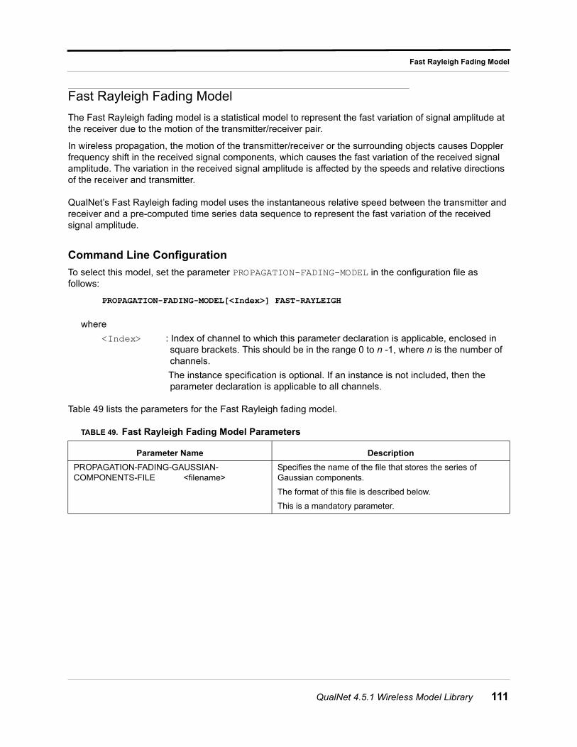
Fast Rayleigh Fading Model
Fast Rayleigh Fading Model
The Fast Rayleigh fading model is a statistical model to represent the fast variation of signal amplitude at the receiver due to the motion of the transmitter/receiver pair.
In wireless propagation, the motion of the transmitter/receiver or the surrounding objects causes Doppler frequency shift in the received signal components, which causes the fast variation of the received signal amplitude. The variation in the received signal amplitude is affected by the speeds and relative directions of the receiver and transmitter.
QualNet’s Fast Rayleigh fading model uses the instantaneous relative speed between the transmitter and receiver and a pre-computed time series data sequence to represent the fast variation of the received signal amplitude.
Command Line Configuration
To select this model, set the parameter PROPAGATION-FADING-MODEL in the configuration file as follows:
PROPAGATION-FADING-MODEL[<Index>] FAST-RAYLEIGH
where
<Index> : Index of channel to which this parameter declaration is applicable, enclosed in square brackets. This should be in the range 0 to n -1, where n is the number of channels.
The instance specification is optional. If an instance is not included, then the parameter declaration is applicable to all channels.
Table 49 lists the parameters for the Fast Rayleigh fading model.
TABLE 49. Fast Rayleigh Fading Model Parameters
Parameter Name Description
PROPAGATION-FADING-GAUSSIAN-COMPONENTS-FILE <filename>
Specifies the name of the file that stores the series of Gaussian components.
The format of this file is described below.
This is a mandatory parameter.
QualNet 4.5.1 Wireless Model Library 111
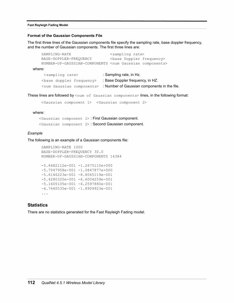
Fast Rayleigh Fading Model
Format of the Gaussian Components File
The first three lines of the Gaussian components file specify the sampling rate, base doppler frequency, and the number of Gaussian components. The first three lines are:
SAMPLING-RATE <sampling rate> BASE-DOPPLER-FREQUENCY <base Doppler frequency> NUMBER-OF-GAUSSIAN-COMPONENTS <num Gaussian components>
where:
<sampling rate> : Sampling rate, in Hz.
<base doppler frequency> : Base Doppler frequency, in HZ.
<num Gaussian components> : Number of Gaussian components in the file.
These lines are followed by <num of Gaussian components> lines, in the following format:
<Gaussian component 1> <Gaussian component 2>
where:
<Gaussian component 1> : First Gaussian component.
<Gaussian component 2> : Second Gaussian component.
Example
The following is an example of a Gaussian components file:
SAMPLING-RATE 1000BASE-DOPPLER-FREQUENCY 30.0NUMBER-OF-GAUSSIAN-COMPONENTS 16384
-5.6482112e-001 -1.2675110e+000-5.7047958e-001 -1.0847877e+000-5.6146223e-001 -8.8065119e-001-5.4280320e-001 -6.6004259e-001-5.1605105e-001 -4.2597880e-001-4.7640535e-001 -1.8909923e-001...
Statistics
There are no statistics generated for the Fast Rayleigh Fading model.
112 QualNet 4.5.1 Wireless Model Library
File-based Mobility Model
File-based Mobility Model
The file-based mobility model uses waypoints for each node specified by the user in a node position file. Each waypoint is a specification of a node’s location and (optionally) orientation and the time at which the node arrives at that location. The node moves from one waypoint to the next in a straight line at a constant speed.
Command Line Configuration
To select this model, set the parameter MOBILITY in the configuration file as follows:
[<Qualifier>] MOBILITY FILE
where
<Qualifier> : Node identifier(s) to which this parameter declaration is applicable, enclosed in square brackets. If a qualifier is not included, the parameter declaration is applicable to all nodes.
The parameters for the file-based mobility model are described in Table 50.
Format of the Node Position File
Each line in the node position file has the following format:
<nodeID> <simulation-time> <position>
where
<nodeID> : Node identifier.
<simulation-time> : Simulation time. For the initial node position, this should be 0. See QualNet 4.5 User’s Guide for the format for specifying time.
<position> : Node position. The node position is specified as the coordinates in Cartesian or Lat-Lon-Alt system, optionally followed by the orientation (azimuth and elevation). Specifying node orientation is optional and is assumed to be (0.0 0.0) when not specified. See QualNet 4.5 User’s Guide for the format for specifying node positions.
Notes:
1. For each node, the node positions should be sorted (in ascending order) by simulation time.
2. Each node position specification should be on a single line by itself.
3. Comments can be entered any where in the node position file.
TABLE 50. File-based Mobility Model Parameters
Parameter Name Description
NODE-POSITION-FILE <filename> Specifies the name of the node position file.
The same file is also used if the file-based node-placement model is used. The format of this file is described below.
This is a mandatory parameter if the file-based mobility is selected.
QualNet 4.5.1 Wireless Model Library 113
File-based Mobility Model
Example
The following lines show a segment of a node position file:
1 0 (35.130587432702, -116.72249286971918, 0.0) 0 01 10S (35.12977099236641, -116.53095393408505, 0.0) 0.0 0.01 20S (35.12977099236641, -116.39738452458609, 0.0)...1 60S (35.36132315521628, -116.2700276457615, 0.0) 1 70S (35.465648854961835, -116.26692138042432, 0.0) 0.0 0.02 0 (35.16793886702846, -116.72149633406089, 0.0) 0 02 10S (35.16897959183674, -116.58344129312579, 0.0) 30.0 0.02 20S (35.16938775510204, -116.4518964383234, 0.0) 30.0 45.0...
Statistics
There are no statistics generated for the file-based mobility model.
114 QualNet 4.5.1 Wireless Model Library
Fisheye State Routing Protocol
Fisheye State Routing Protocol
Fisheye State Routing (FSR) is a link state type protocol that maintains a topology map at each node. FSR differs from the standard link state algorithm by the following:
• Having only neighboring nodes exchange the link state information
• Utilizing only time-triggered, not event-triggered link state exchanges
• Using different exchange intervals for nearby versus far away nodes
Command Line Configuration
To select FSR as the routing protocol, place the following entry in *.config:
ROUTING-PROTOCOL FISHEYE
Table 51 shows the Fisheye State Routing parameters.
Statistics
Table 52 shows the statistics collected by Fisheye:
TABLE 51. Fisheye State Routing Parameters
Parameter Description
FISHEYE-SCOPE <value> Specifies the scope limitation of local routing.
The default value is 2.
FISHEYE-INTRA-UPDATE-INTERVAL <value>
Specifies the routing table update frequency within the Fisheye scope.
The default value is 5S.
FISHEYE-INTER-UPDATE-INTERVAL <value
Specifies the routing table update frequency outside of the Fisheye scope.
The default value is 15S.
FISHEYE-NEIGHBOR-TIMEOUT-INTERVAL <value>
Specifies the occurrence of the timeout event for the expiration period of the neighbor list.
The default value is 15S.
TABLE 52. Fisheye Statistics
Statistic Description
Number of intra scope updates sent Total number of inner scope topology updates.
Number of inter scope updates sent Total number of outer scope topology updates.
Number of control packets received Total number of control packets received from transport layer.
Control Overhead in Bytes Total number of control overheads in bytes.
QualNet 4.5.1 Wireless Model Library 115
Free-space Pathloss Model
Free-space Pathloss Model
The free-space pathloss model assumes an omni-directional line-of-sight propagation path. The signal strength decays with the square of the distance between the transmitter and receiver.
Command Line Configuration
To select this model, set the parameter PROPAGATION-PATHLOSS-MODEL in the configuration file as follows:
PROPAGATION-PATHLOSS-MODEL[<Index>] FREE-SPACE
where
<Index> : Index of channel to which this parameter declaration is applicable, enclosed in square brackets. This should be in the range 0 to n -1, where n is the number of channels.
The instance specification is optional. If an instance is not included, then the parameter declaration is applicable to all channels.
Statistics
There are no statistics collected by the free-space pathloss model.
116 QualNet 4.5.1 Wireless Model Library
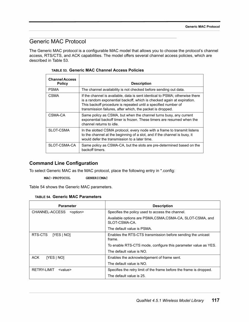
Generic MAC Protocol
Generic MAC Protocol
The Generic MAC protocol is a configurable MAC model that allows you to choose the protocol’s channel access, RTS/CTS, and ACK capabilities. The model offers several channel access policies, which are described in Table 53.
Command Line Configuration
To select Generic MAC as the MAC protocol, place the following entry in *.config:
MAC-PROTOCOL GENERICMAC
Table 54 shows the Generic MAC parameters.
TABLE 53. Generic MAC Channel Access Policies
Channel Access Policy Description
PSMA The channel availability is not checked before sending out data.
CSMA If the channel is available, data is sent identical to PSMA; otherwise there is a random exponential backoff, which is checked again at expiration. This backoff procedure is repeated until a specified number of transmission failures, after which, the packet is dropped.
CSMA-CA Same policy as CSMA, but when the channel turns busy, any current exponential backoff timer is frozen. These timers are resumed when the channel returns to idle.
SLOT-CSMA In the slotted CSMA protocol, every node with a frame to transmit listens to the channel at the beginning of a slot, and if the channel is busy, it would defer the transmission to a later time.
SLOT-CSMA-CA Same policy as CSMA-CA, but the slots are pre-determined based on the backoff timers.
TABLE 54. Generic MAC Parameters
Parameter Description
CHANNEL-ACCESS <option> Specifies the policy used to access the channel.
Available options are PSMA,CSMA,CSMA-CA, SLOT-CSMA, and SLOT-CSMA-CA.
The default value is PSMA.
RTS-CTS [YES | NO] Enables the RTS-CTS transmission before sending the unicast frame.
To enable RTS-CTS mode, configure this parameter value as YES.
The default value is NO.
ACK [YES | NO] Enables the acknowledgement of frame sent.
The default value is NO.
RETRY-LIMIT <value> Specifies the retry limit of the frame before the frame is dropped.
The default value is 25.
QualNet 4.5.1 Wireless Model Library 117
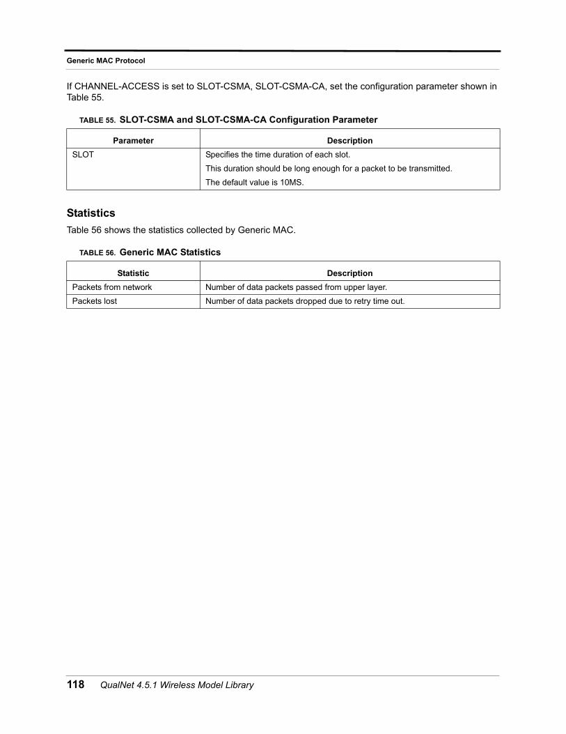
Generic MAC Protocol
If CHANNEL-ACCESS is set to SLOT-CSMA, SLOT-CSMA-CA, set the configuration parameter shown in Table 55.
Statistics
Table 56 shows the statistics collected by Generic MAC.
TABLE 55. SLOT-CSMA and SLOT-CSMA-CA Configuration Parameter
Parameter Description
SLOT Specifies the time duration of each slot.
This duration should be long enough for a packet to be transmitted.
The default value is 10MS.
TABLE 56. Generic MAC Statistics
Statistic Description
Packets from network Number of data packets passed from upper layer.
Packets lost Number of data packets dropped due to retry time out.
118 QualNet 4.5.1 Wireless Model Library
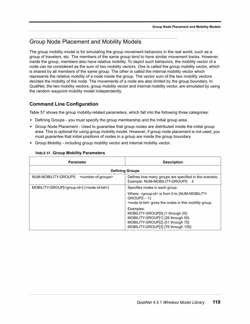
Group Node Placement and Mobility Models
Group Node Placement and Mobility Models
The group mobility model is for simulating the group movement behaviors in the real world, such as a group of travelers, etc. The members of the same group tend to have similar movement tracks. However, inside the group, members also have relative mobility. To depict such behaviors, the mobility vector of a node can be considered as the sum of two mobility vectors. One is called the group mobility vector, which is shared by all members of the same group. The other is called the internal mobility vector which represents the relative mobility of a node inside the group. The vector sum of the two mobility vectors decides the mobility of the node. The movements of a node are also limited by the group boundary. In QualNet, the two mobility vectors, group mobility vector and internal mobility vector, are simulated by using the random waypoint mobility model independently.
Command Line Configuration
Table 57 shows the group mobility-related parameters, which fall into the following three categories:
• Defining Groups - you must specify the group membership and the initial group area.
• Group Node Placement - Used to guarantee that group nodes are distributed inside the initial group area. This is optional for using group mobility model. However, if group node placement is not used, you must guarantee that initial positions of nodes in a group are inside the group boundary.
• Group Mobility - including group mobility vector and internal mobility vector.
TABLE 57. Group Mobility Parameters
Parameter Description
Defining Groups
NUM-MOBILITY-GROUPS <number-of-groups> Defines how many groups are specified in this scenario.Example: NUM-MOBILITY-GROUPS 4
MOBILITY-GROUP[<group-id>] {<node-id-list>} Specifies nodes in each group.
Where: <group-id> is from 0 to (NUM-MOBILITY-GROUPS – 1).<node-id-list> gives the nodes in this mobility group.
Examples:MOBILITY-GROUP[0] {1 through 25}MOBILITY-GROUP[1] {26 through 50}MOBILITY-GROUP[2] {51 through 75}MOBILITY-GROUP[3] {76 through 100}
QualNet 4.5.1 Wireless Model Library 119
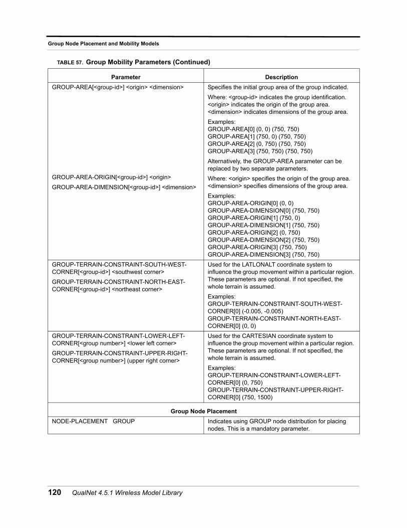
Group Node Placement and Mobility Models
GROUP-AREA[<group-id>] <origin> <dimension>
GROUP-AREA-ORIGIN[<group-id>] <origin>
GROUP-AREA-DIMENSION[<group-id>] <dimension>
Specifies the initial group area of the group indicated.
Where: <group-id> indicates the group identification. <origin> indicates the origin of the group area. <dimension> indicates dimensions of the group area.
Examples:GROUP-AREA[0] (0, 0) (750, 750)GROUP-AREA[1] (750, 0) (750, 750)GROUP-AREA[2] (0, 750) (750, 750)GROUP-AREA[3] (750, 750) (750, 750)
Alternatively, the GROUP-AREA parameter can be replaced by two separate parameters.
Where: <origin> specifies the origin of the group area.<dimension> specifies dimensions of the group area.
Examples:GROUP-AREA-ORIGIN[0] (0, 0)GROUP-AREA-DIMENSION[0] (750, 750)GROUP-AREA-ORIGIN[1] (750, 0)GROUP-AREA-DIMENSION[1] (750, 750)GROUP-AREA-ORIGIN[2] (0, 750)GROUP-AREA-DIMENSION[2] (750, 750)GROUP-AREA-ORIGIN[3] (750, 750)GROUP-AREA-DIMENSION[3] (750, 750)
GROUP-TERRAIN-CONSTRAINT-SOUTH-WEST-CORNER[<group-id>] <southwest corner>
GROUP-TERRAIN-CONSTRAINT-NORTH-EAST-CORNER[<group-id>] <northeast corner>
Used for the LATLONALT coordinate system to influence the group movement within a particular region. These parameters are optional. If not specified, the whole terrain is assumed.
Examples:GROUP-TERRAIN-CONSTRAINT-SOUTH-WEST-CORNER[0] (-0.005, -0.005)GROUP-TERRAIN-CONSTRAINT-NORTH-EAST-CORNER[0] (0, 0)
GROUP-TERRAIN-CONSTRAINT-LOWER-LEFT-CORNER[<group number>] <lower left corner>
GROUP-TERRAIN-CONSTRAINT-UPPER-RIGHT-CORNER[<group number>] (upper right corner>
Used for the CARTESIAN coordinate system to influence the group movement within a particular region. These parameters are optional. If not specified, the whole terrain is assumed.
Examples:GROUP-TERRAIN-CONSTRAINT-LOWER-LEFT-CORNER[0] (0, 750)GROUP-TERRAIN-CONSTRAINT-UPPER-RIGHT-CORNER[0] (750, 1500)
Group Node Placement
NODE-PLACEMENT GROUP Indicates using GROUP node distribution for placing nodes. This is a mandatory parameter.
TABLE 57. Group Mobility Parameters (Continued)
Parameter Description
120 QualNet 4.5.1 Wireless Model Library
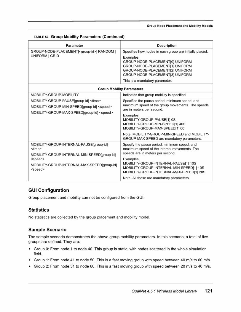
Group Node Placement and Mobility Models
GUI Configuration
Group placement and mobility can not be configured from the GUI.
Statistics
No statistics are collected by the group placement and mobility model.
Sample Scenario
The sample scenario demonstrates the above group mobility parameters. In this scenario, a total of five groups are defined. They are:
• Group 0: From node 1 to node 40. This group is static, with nodes scattered in the whole simulation field.
• Group 1: From node 41 to node 50. This is a fast moving group with speed between 40 m/s to 60 m/s.
• Group 2: From node 51 to node 60. This is a fast moving group with speed between 20 m/s to 40 m/s.
GROUP-NODE-PLACEMENT[<group-id>] RANDOM | UNIFORM | GRID
Specifies how nodes in each group are initially placed.
Examples:GROUP-NODE-PLACEMENT[0] UNIFORMGROUP-NODE-PLACEMENT[1] UNIFORMGROUP-NODE-PLACEMENT[2] UNIFORMGROUP-NODE-PLACEMENT[3] UNIFORM
This is a mandatory parameter.
Group Mobility Parameters
MOBILITY-GROUP-MOBILITY Indicates that group mobility is specified.
MOBILITY-GROUP-PAUSE[group-id] <time>
MOBILITY-GROUP-MIN-SPEED[group-id] <speed>
MOBILITY-GROUP-MAX-SPEED[group-id] <speed>
Specifies the pause period, minimum speed, and maximum speed of the group movements. The speeds are in meters per second.
Examples:MOBILITY-GROUP-PAUSE[1] 0SMOBILITY-GROUP-MIN-SPEED[1] 40SMOBILITY-GROUP-MAX-SPEED[1] 60
Note: MOBILITY-GROUP-MIN-SPEED and MOBILITY-GROUP-MAX-SPEED are mandatory parameters.
MOBILITY-GROUP-INTERNAL-PAUSE[group-id] <time>
MOBILITY-GROUP-INTERNAL-MIN-SPEED[group-id] <speed>
MOBILITY-GROUP-INTERNAL-MAX-SPEED[group-id] <speed>
Specify the pause period, minimum speed, and maximum speed of the internal movements. The speeds are in meters per second.
Examples:MOBILITY-GROUP-INTERNAL-PAUSE[1] 10SMOBILITY-GROUP-INTERNAL-MIN-SPEED[1] 10SMOBILITY-GROUP-INTERNAL-MAX-SPEED[1] 20S
Note: All these are mandatory parameters.
TABLE 57. Group Mobility Parameters (Continued)
Parameter Description
QualNet 4.5.1 Wireless Model Library 121
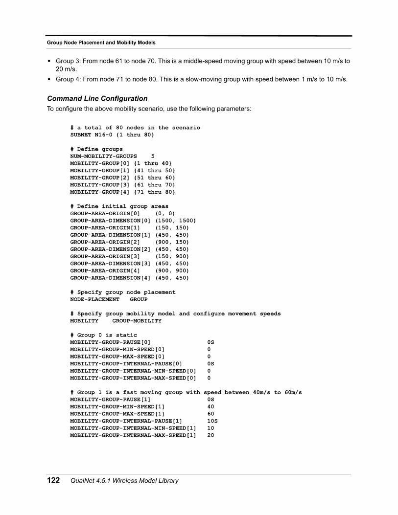
Group Node Placement and Mobility Models
• Group 3: From node 61 to node 70. This is a middle-speed moving group with speed between 10 m/s to 20 m/s.
• Group 4: From node 71 to node 80. This is a slow-moving group with speed between 1 m/s to 10 m/s.
Command Line ConfigurationTo configure the above mobility scenario, use the following parameters:
# a total of 80 nodes in the scenarioSUBNET N16-0 {1 thru 80}
# Define groupsNUM-MOBILITY-GROUPS 5MOBILITY-GROUP[0] {1 thru 40}MOBILITY-GROUP[1] {41 thru 50}MOBILITY-GROUP[2] {51 thru 60}MOBILITY-GROUP[3] {61 thru 70}MOBILITY-GROUP[4] {71 thru 80}
# Define initial group areasGROUP-AREA-ORIGIN[0] (0, 0)GROUP-AREA-DIMENSION[0] (1500, 1500)GROUP-AREA-ORIGIN[1] (150, 150)GROUP-AREA-DIMENSION[1] (450, 450)GROUP-AREA-ORIGIN[2] (900, 150)GROUP-AREA-DIMENSION[2] (450, 450)GROUP-AREA-ORIGIN[3] (150, 900)GROUP-AREA-DIMENSION[3] (450, 450)GROUP-AREA-ORIGIN[4] (900, 900)GROUP-AREA-DIMENSION[4] (450, 450)
# Specify group node placementNODE-PLACEMENT GROUP
# Specify group mobility model and configure movement speedsMOBILITY GROUP-MOBILITY
# Group 0 is staticMOBILITY-GROUP-PAUSE[0] 0SMOBILITY-GROUP-MIN-SPEED[0] 0MOBILITY-GROUP-MAX-SPEED[0] 0MOBILITY-GROUP-INTERNAL-PAUSE[0] 0SMOBILITY-GROUP-INTERNAL-MIN-SPEED[0] 0MOBILITY-GROUP-INTERNAL-MAX-SPEED[0] 0
# Group 1 is a fast moving group with speed between 40m/s to 60m/sMOBILITY-GROUP-PAUSE[1] 0SMOBILITY-GROUP-MIN-SPEED[1] 40MOBILITY-GROUP-MAX-SPEED[1] 60MOBILITY-GROUP-INTERNAL-PAUSE[1] 10SMOBILITY-GROUP-INTERNAL-MIN-SPEED[1] 10MOBILITY-GROUP-INTERNAL-MAX-SPEED[1] 20
122 QualNet 4.5.1 Wireless Model Library
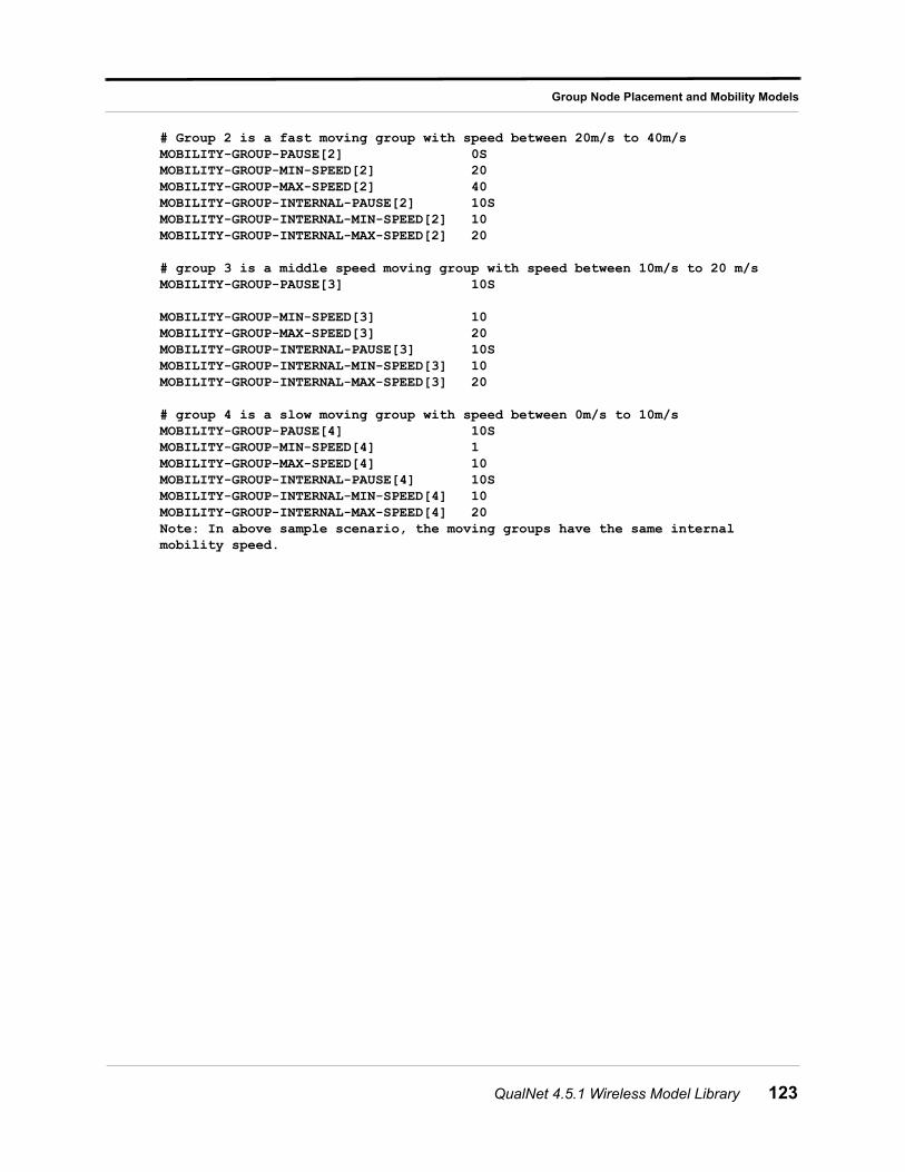
Group Node Placement and Mobility Models
# Group 2 is a fast moving group with speed between 20m/s to 40m/sMOBILITY-GROUP-PAUSE[2] 0SMOBILITY-GROUP-MIN-SPEED[2] 20MOBILITY-GROUP-MAX-SPEED[2] 40MOBILITY-GROUP-INTERNAL-PAUSE[2] 10SMOBILITY-GROUP-INTERNAL-MIN-SPEED[2] 10MOBILITY-GROUP-INTERNAL-MAX-SPEED[2] 20
# group 3 is a middle speed moving group with speed between 10m/s to 20 m/sMOBILITY-GROUP-PAUSE[3] 10S
MOBILITY-GROUP-MIN-SPEED[3] 10MOBILITY-GROUP-MAX-SPEED[3] 20MOBILITY-GROUP-INTERNAL-PAUSE[3] 10SMOBILITY-GROUP-INTERNAL-MIN-SPEED[3] 10MOBILITY-GROUP-INTERNAL-MAX-SPEED[3] 20
# group 4 is a slow moving group with speed between 0m/s to 10m/sMOBILITY-GROUP-PAUSE[4] 10SMOBILITY-GROUP-MIN-SPEED[4] 1MOBILITY-GROUP-MAX-SPEED[4] 10MOBILITY-GROUP-INTERNAL-PAUSE[4] 10SMOBILITY-GROUP-INTERNAL-MIN-SPEED[4] 10MOBILITY-GROUP-INTERNAL-MAX-SPEED[4] 20Note: In above sample scenario, the moving groups have the same internal mobility speed.
QualNet 4.5.1 Wireless Model Library 123
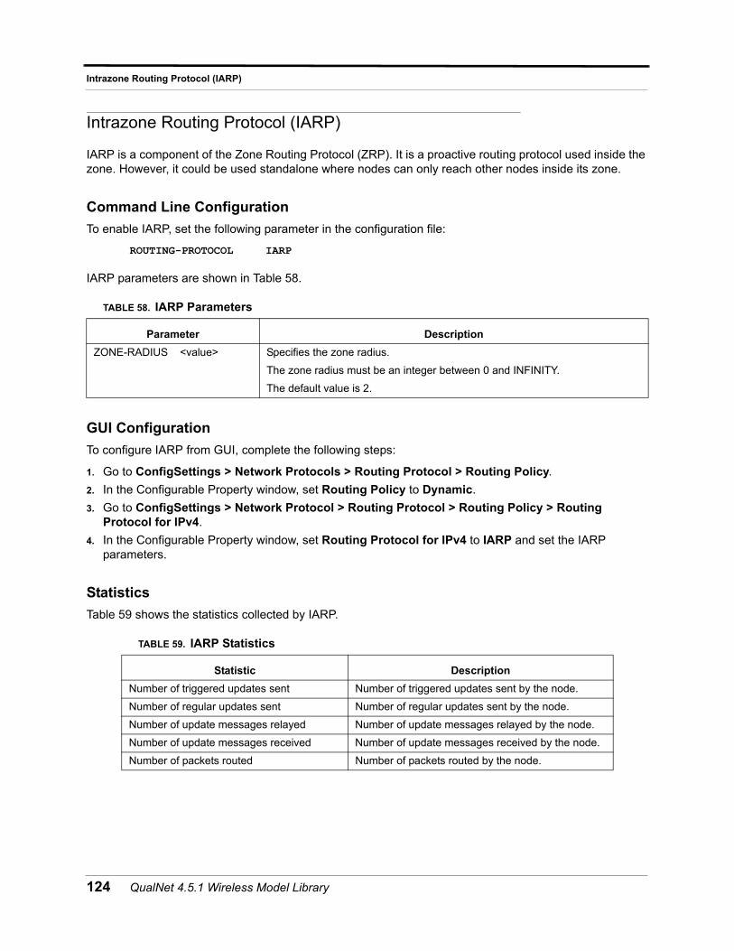
Intrazone Routing Protocol (IARP)
Intrazone Routing Protocol (IARP)
IARP is a component of the Zone Routing Protocol (ZRP). It is a proactive routing protocol used inside the zone. However, it could be used standalone where nodes can only reach other nodes inside its zone.
Command Line Configuration
To enable IARP, set the following parameter in the configuration file:
ROUTING-PROTOCOL IARP
IARP parameters are shown in Table 58.
GUI Configuration
To configure IARP from GUI, complete the following steps:
1. Go to ConfigSettings > Network Protocols > Routing Protocol > Routing Policy.
2. In the Configurable Property window, set Routing Policy to Dynamic.
3. Go to ConfigSettings > Network Protocol > Routing Protocol > Routing Policy > Routing Protocol for IPv4.
4. In the Configurable Property window, set Routing Protocol for IPv4 to IARP and set the IARP parameters.
Statistics
Table 59 shows the statistics collected by IARP.
TABLE 58. IARP Parameters
Parameter Description
ZONE-RADIUS <value> Specifies the zone radius.
The zone radius must be an integer between 0 and INFINITY.
The default value is 2.
TABLE 59. IARP Statistics
Statistic Description
Number of triggered updates sent Number of triggered updates sent by the node.
Number of regular updates sent Number of regular updates sent by the node.
Number of update messages relayed Number of update messages relayed by the node.
Number of update messages received Number of update messages received by the node.
Number of packets routed Number of packets routed by the node.
124 QualNet 4.5.1 Wireless Model Library
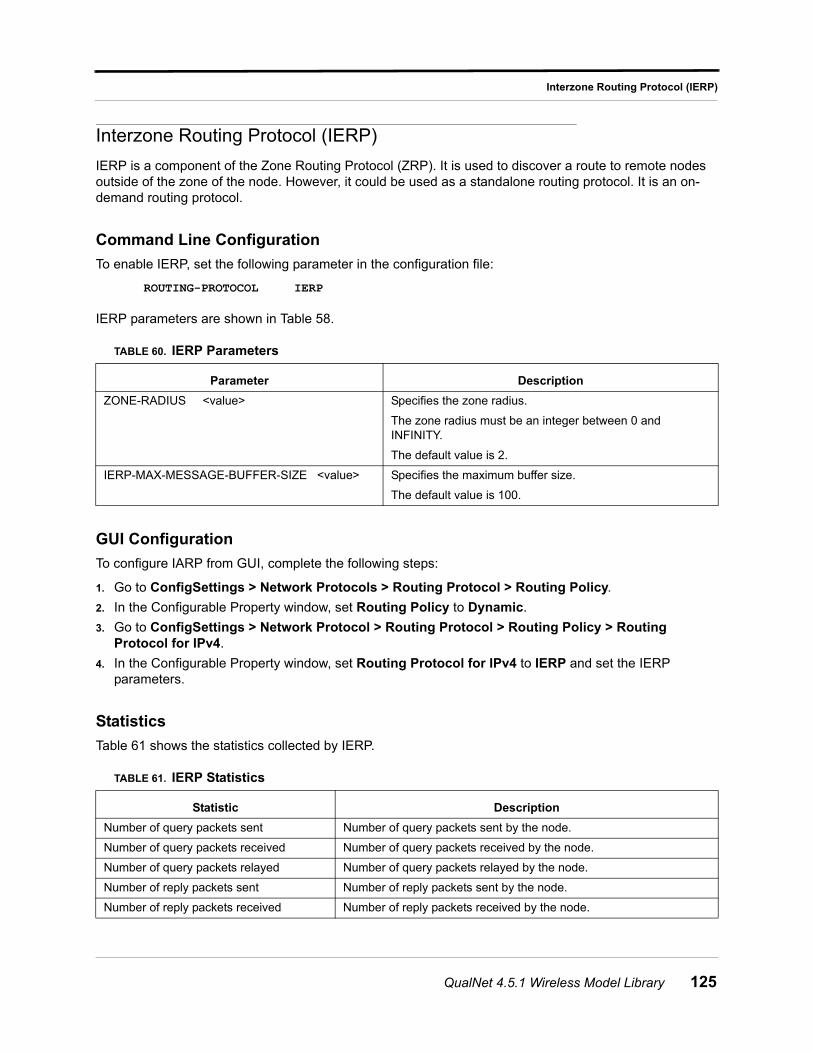
Interzone Routing Protocol (IERP)
Interzone Routing Protocol (IERP)
IERP is a component of the Zone Routing Protocol (ZRP). It is used to discover a route to remote nodes outside of the zone of the node. However, it could be used as a standalone routing protocol. It is an on-demand routing protocol.
Command Line Configuration
To enable IERP, set the following parameter in the configuration file:
ROUTING-PROTOCOL IERP
IERP parameters are shown in Table 58.
GUI Configuration
To configure IARP from GUI, complete the following steps:
1. Go to ConfigSettings > Network Protocols > Routing Protocol > Routing Policy.
2. In the Configurable Property window, set Routing Policy to Dynamic.
3. Go to ConfigSettings > Network Protocol > Routing Protocol > Routing Policy > Routing Protocol for IPv4.
4. In the Configurable Property window, set Routing Protocol for IPv4 to IERP and set the IERP parameters.
Statistics
Table 61 shows the statistics collected by IERP.
TABLE 60. IERP Parameters
Parameter Description
ZONE-RADIUS <value> Specifies the zone radius.
The zone radius must be an integer between 0 and INFINITY.
The default value is 2.
IERP-MAX-MESSAGE-BUFFER-SIZE <value> Specifies the maximum buffer size.
The default value is 100.
TABLE 61. IERP Statistics
Statistic Description
Number of query packets sent Number of query packets sent by the node.
Number of query packets received Number of query packets received by the node.
Number of query packets relayed Number of query packets relayed by the node.
Number of reply packets sent Number of reply packets sent by the node.
Number of reply packets received Number of reply packets received by the node.
QualNet 4.5.1 Wireless Model Library 125
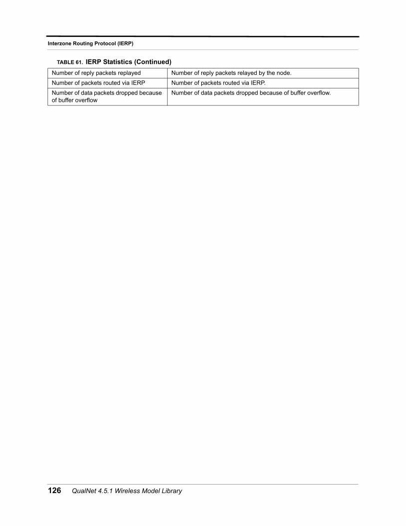
Interzone Routing Protocol (IERP)
Number of reply packets replayed Number of reply packets relayed by the node.
Number of packets routed via IERP Number of packets routed via IERP.
Number of data packets dropped because of buffer overflow
Number of data packets dropped because of buffer overflow.
TABLE 61. IERP Statistics (Continued)
126 QualNet 4.5.1 Wireless Model Library
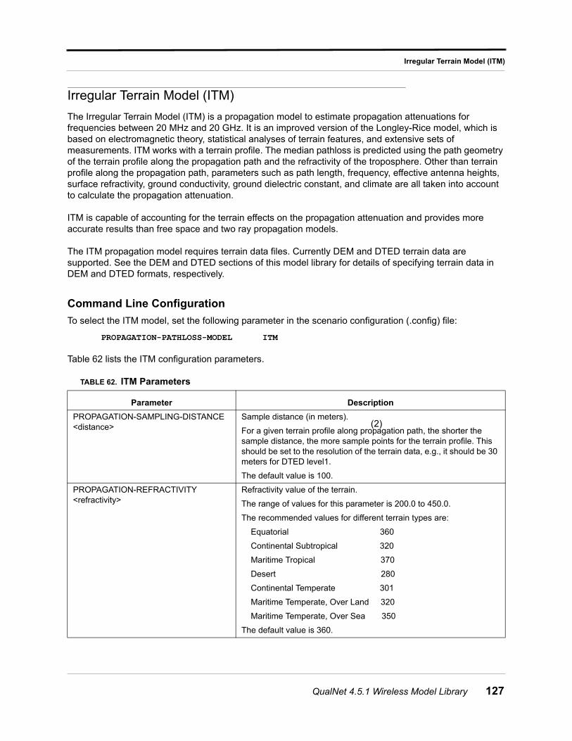
Irregular Terrain Model (ITM)
Irregular Terrain Model (ITM)
The Irregular Terrain Model (ITM) is a propagation model to estimate propagation attenuations for frequencies between 20 MHz and 20 GHz. It is an improved version of the Longley-Rice model, which is based on electromagnetic theory, statistical analyses of terrain features, and extensive sets of measurements. ITM works with a terrain profile. The median pathloss is predicted using the path geometry of the terrain profile along the propagation path and the refractivity of the troposphere. Other than terrain profile along the propagation path, parameters such as path length, frequency, effective antenna heights, surface refractivity, ground conductivity, ground dielectric constant, and climate are all taken into account to calculate the propagation attenuation.
ITM is capable of accounting for the terrain effects on the propagation attenuation and provides more accurate results than free space and two ray propagation models.
The ITM propagation model requires terrain data files. Currently DEM and DTED terrain data are supported. See the DEM and DTED sections of this model library for details of specifying terrain data in DEM and DTED formats, respectively.
Command Line Configuration
To select the ITM model, set the following parameter in the scenario configuration (.config) file:
PROPAGATION-PATHLOSS-MODEL ITM
Table 62 lists the ITM configuration parameters.
TABLE 62. ITM Parameters
Parameter Description
PROPAGATION-SAMPLING-DISTANCE <distance>
Sample distance (in meters).
For a given terrain profile along propagation path, the shorter the sample distance, the more sample points for the terrain profile. This should be set to the resolution of the terrain data, e.g., it should be 30 meters for DTED level1.
The default value is 100.
PROPAGATION-REFRACTIVITY <refractivity>
Refractivity value of the terrain.
The range of values for this parameter is 200.0 to 450.0.
The recommended values for different terrain types are:
Equatorial 360
Continental Subtropical 320
Maritime Tropical 370
Desert 280
Continental Temperate 301
Maritime Temperate, Over Land 320
Maritime Temperate, Over Sea 350
The default value is 360.
(2)
QualNet 4.5.1 Wireless Model Library 127
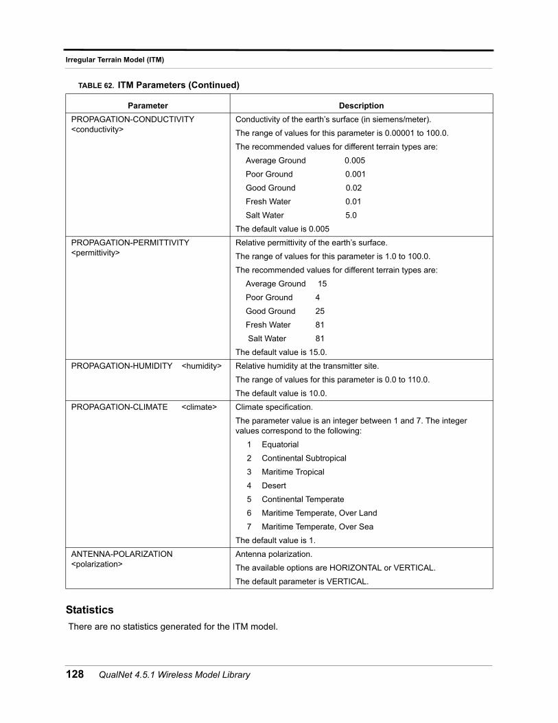
Irregular Terrain Model (ITM)
Statistics
There are no statistics generated for the ITM model.
PROPAGATION-CONDUCTIVITY <conductivity>
Conductivity of the earth’s surface (in siemens/meter).
The range of values for this parameter is 0.00001 to 100.0.
The recommended values for different terrain types are:
Average Ground 0.005
Poor Ground 0.001
Good Ground 0.02
Fresh Water 0.01
Salt Water 5.0
The default value is 0.005
PROPAGATION-PERMITTIVITY <permittivity>
Relative permittivity of the earth’s surface.
The range of values for this parameter is 1.0 to 100.0.
The recommended values for different terrain types are:
Average Ground 15
Poor Ground 4
Good Ground 25
Fresh Water 81
Salt Water 81
The default value is 15.0.
PROPAGATION-HUMIDITY <humidity> Relative humidity at the transmitter site.
The range of values for this parameter is 0.0 to 110.0.
The default value is 10.0.
PROPAGATION-CLIMATE <climate> Climate specification.
The parameter value is an integer between 1 and 7. The integer values correspond to the following:
1 Equatorial
2 Continental Subtropical
3 Maritime Tropical
4 Desert
5 Continental Temperate
6 Maritime Temperate, Over Land
7 Maritime Temperate, Over Sea
The default value is 1.
ANTENNA-POLARIZATION <polarization>
Antenna polarization.
The available options are HORIZONTAL or VERTICAL.
The default parameter is VERTICAL.
TABLE 62. ITM Parameters (Continued)
Parameter Description
128 QualNet 4.5.1 Wireless Model Library
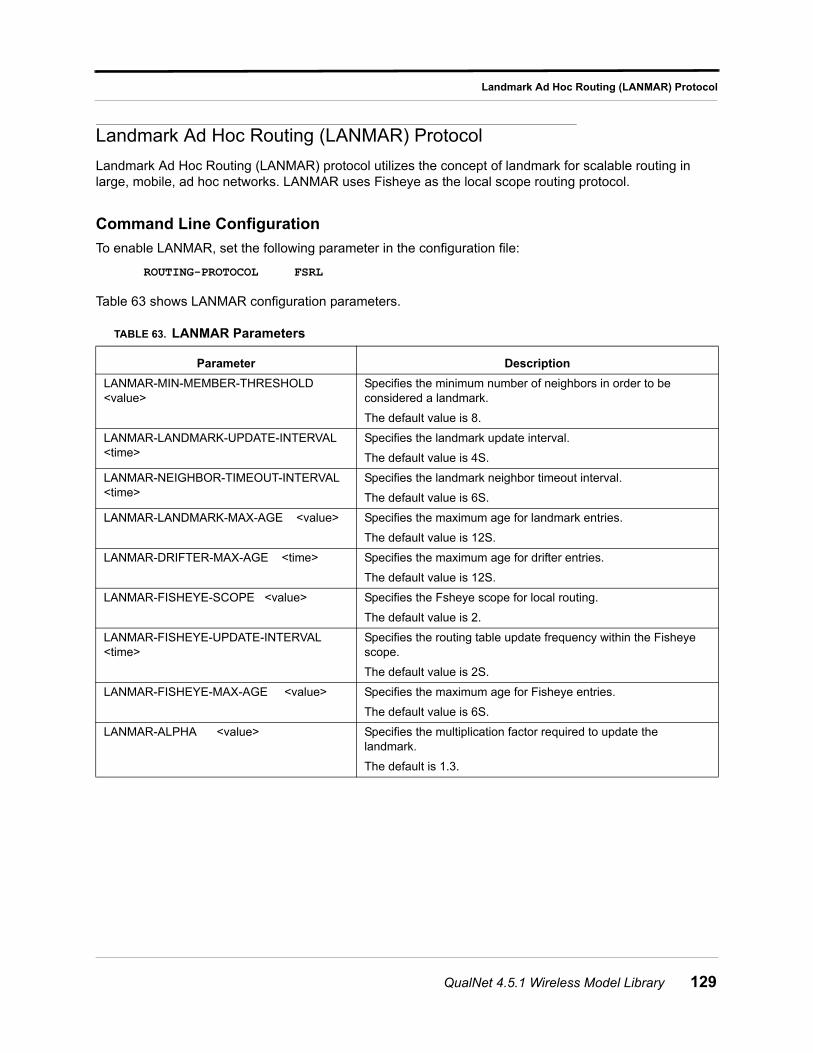
Landmark Ad Hoc Routing (LANMAR) Protocol
Landmark Ad Hoc Routing (LANMAR) Protocol
Landmark Ad Hoc Routing (LANMAR) protocol utilizes the concept of landmark for scalable routing in large, mobile, ad hoc networks. LANMAR uses Fisheye as the local scope routing protocol.
Command Line Configuration
To enable LANMAR, set the following parameter in the configuration file:
ROUTING-PROTOCOL FSRL
Table 63 shows LANMAR configuration parameters.
TABLE 63. LANMAR Parameters
Parameter Description
LANMAR-MIN-MEMBER-THRESHOLD <value>
Specifies the minimum number of neighbors in order to be considered a landmark.
The default value is 8.
LANMAR-LANDMARK-UPDATE-INTERVAL <time>
Specifies the landmark update interval.
The default value is 4S.
LANMAR-NEIGHBOR-TIMEOUT-INTERVAL <time>
Specifies the landmark neighbor timeout interval.
The default value is 6S.
LANMAR-LANDMARK-MAX-AGE <value> Specifies the maximum age for landmark entries.
The default value is 12S.
LANMAR-DRIFTER-MAX-AGE <time> Specifies the maximum age for drifter entries.
The default value is 12S.
LANMAR-FISHEYE-SCOPE <value> Specifies the Fsheye scope for local routing.
The default value is 2.
LANMAR-FISHEYE-UPDATE-INTERVAL <time>
Specifies the routing table update frequency within the Fisheye scope.
The default value is 2S.
LANMAR-FISHEYE-MAX-AGE <value> Specifies the maximum age for Fisheye entries.
The default value is 6S.
LANMAR-ALPHA <value> Specifies the multiplication factor required to update the landmark.
The default is 1.3.
QualNet 4.5.1 Wireless Model Library 129
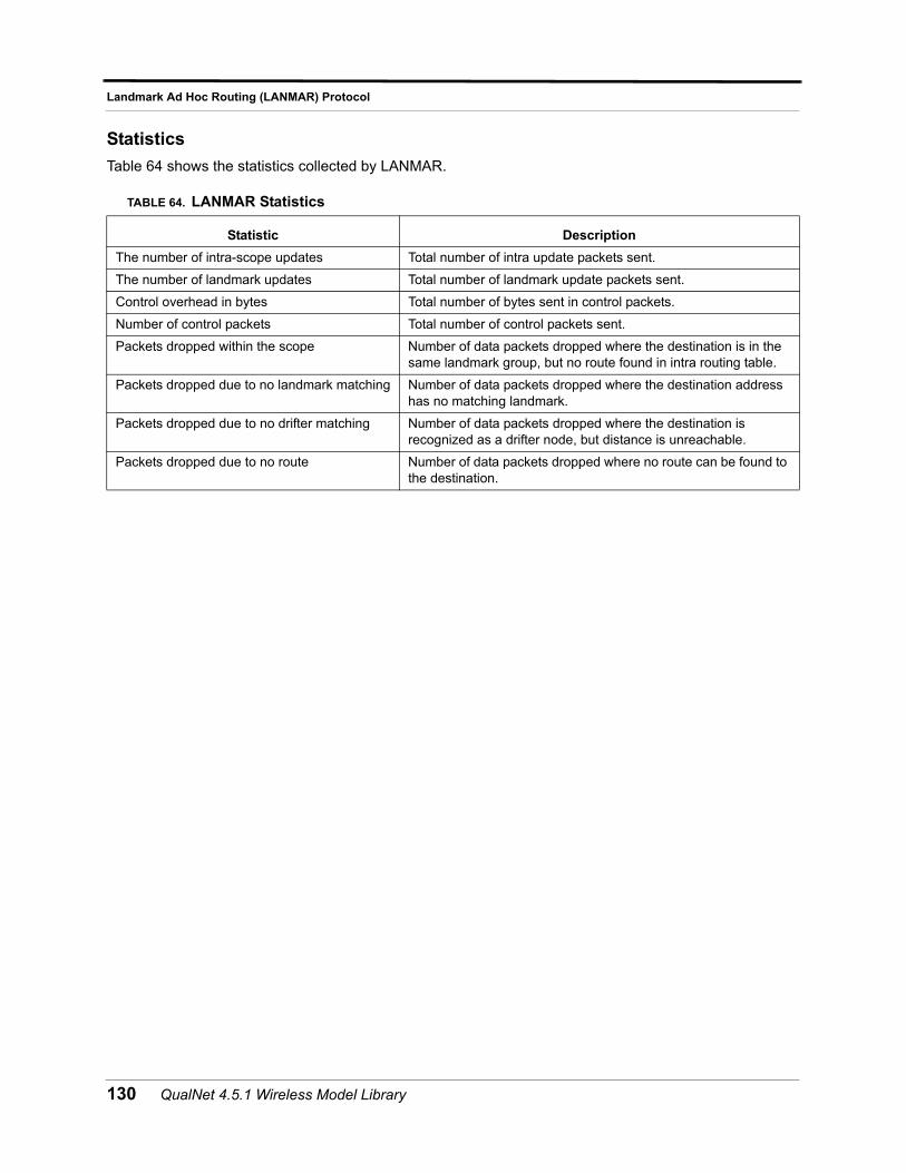
Landmark Ad Hoc Routing (LANMAR) Protocol
Statistics
Table 64 shows the statistics collected by LANMAR.
TABLE 64. LANMAR Statistics
Statistic Description
The number of intra-scope updates Total number of intra update packets sent.
The number of landmark updates Total number of landmark update packets sent.
Control overhead in bytes Total number of bytes sent in control packets.
Number of control packets Total number of control packets sent.
Packets dropped within the scope Number of data packets dropped where the destination is in the same landmark group, but no route found in intra routing table.
Packets dropped due to no landmark matching Number of data packets dropped where the destination address has no matching landmark.
Packets dropped due to no drifter matching Number of data packets dropped where the destination is recognized as a drifter node, but distance is unreachable.
Packets dropped due to no route Number of data packets dropped where no route can be found to the destination.
130 QualNet 4.5.1 Wireless Model Library
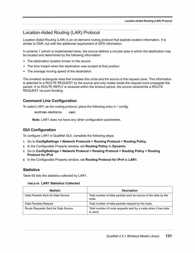
Location-Aided Routing (LAR) Protocol
Location-Aided Routing (LAR) Protocol
Location-Aided Routing (LAR) is an on-demand routing protocol that exploits location information. It is similar to DSR, but with the additional requirement of GPS information.
In scheme 1 (which is implemented here), the source defines a circular area in which the destination may be located and determined by the following information:
• The destination location known to the source
• The time instant when the destination was located at that position
• The average moving speed of the destination.
The smallest rectangular area that includes this circle and the source is the request zone. This information is attached to a ROUTE REQUEST by the source and only nodes inside the request zone propagate the packet. If no ROUTE REPLY is received within the timeout period, the source retransmits a ROUTE REQUEST via pure flooding.
Command Line Configuration
To select LAR1 as the routing protocol, place the following entry in *.config:
ROUTING-PROTOCOL LAR1
Note: LAR1 does not have any other configuration parameters.
GUI Configuration
To configure LAR1 in QualNet GUI, complete the following steps:
1. Go to ConfigSettings > Network Protocols > Routing Protocol > Routing Policy.
2. In the Configurable Property window, set Routing Policy to Dynamic.
3. Go to ConfigSettings > Network Protocol > Routing Protocol > Routing Policy > Routing Protocol for IPv4.
4. In the Configurable Property window, set Routing Protocol for IPv4 to LAR1.
Statistics
Table 65 lists the statistics collected by LAR1.
TABLE 65. LAR1 Statistics Collected
Statistic Description
Data Packets Sent As Data Source Total number of data packets sent as source of the data by the node.
Data Packets Relayed Total number of data packets relayed by the node.
Route Requests Sent As Data Source Total number of route requests sent by a node when it has data to send.
QualNet 4.5.1 Wireless Model Library 131
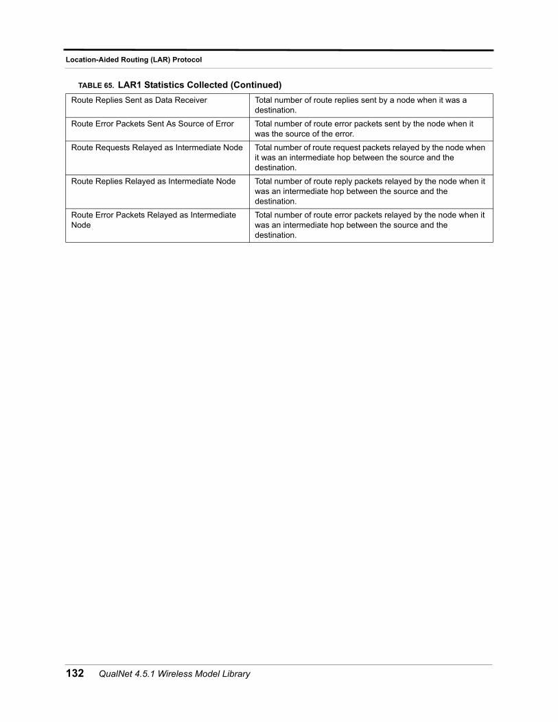
Location-Aided Routing (LAR) Protocol
Route Replies Sent as Data Receiver Total number of route replies sent by a node when it was a destination.
Route Error Packets Sent As Source of Error Total number of route error packets sent by the node when it was the source of the error.
Route Requests Relayed as Intermediate Node Total number of route request packets relayed by the node when it was an intermediate hop between the source and the destination.
Route Replies Relayed as Intermediate Node Total number of route reply packets relayed by the node when it was an intermediate hop between the source and the destination.
Route Error Packets Relayed as Intermediate Node
Total number of route error packets relayed by the node when it was an intermediate hop between the source and the destination.
TABLE 65. LAR1 Statistics Collected (Continued)
132 QualNet 4.5.1 Wireless Model Library
Lognormal Shadowing Model
Lognormal Shadowing Model
The lognormal shadowing model is suitable for a scenario with mobility and obstructions within the propagation environment. In this model, the shadowing value follows a log-normal distribution with a user-specified standard deviation. In general, this value should be in the range of 4 to 12 dB depending on the density of obstructions within the propagation environment.
Command Line Configuration
To select this model, set the parameter PROPAGATION-SHADOWING-MODEL in the configuration file as follows:
PROPAGATION-SHADOWING-MODEL[<Index>] LOGNORMAL
where
<Index> : Index of channel to which this parameter declaration is applicable, enclosed in square brackets. This should be in the range 0 to n -1, where n is the number of channels.
The instance specification is optional. If an instance is not included, then the parameter declaration is applicable to all channels.
Table 66 lists the parameters for the lognormal shadowing model.
Statistics
There are no statistics collected by the lognormal shadowing model.
TABLE 66. Lognormal Shadowing Model Parameters
Parameter Name Description
PROPAGATION-SHADOWING-MEAN <value> Standard deviation of the log-normal distribution.
The higher the density of obstructions within the propagation environment, the higher this value should be.
QualNet 4.5.1 Wireless Model Library 133
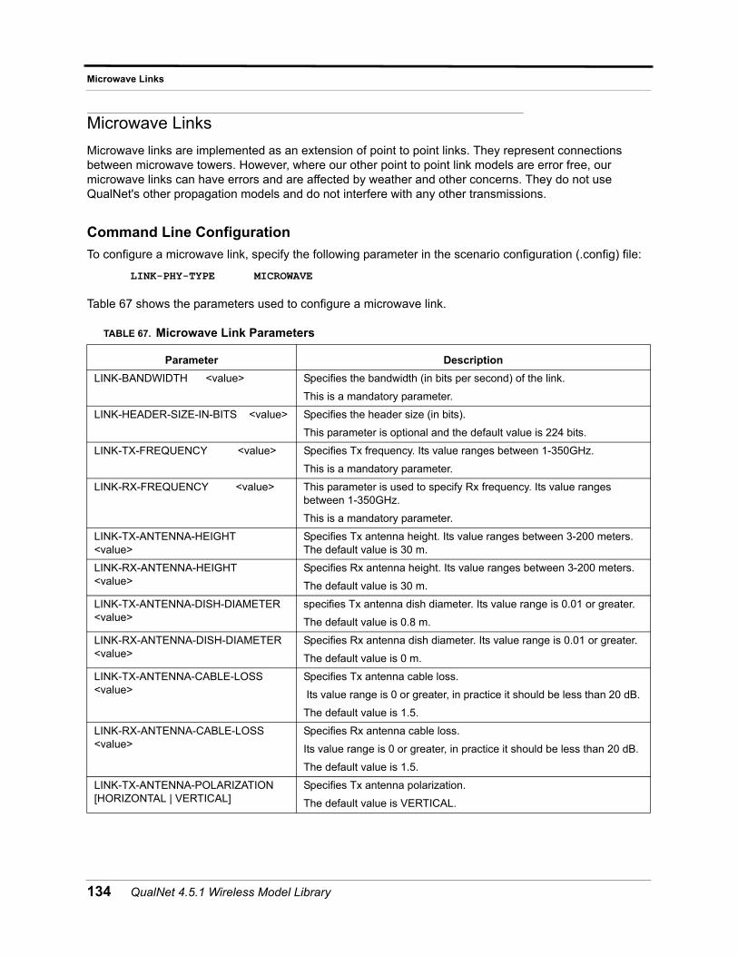
Microwave Links
Microwave Links
Microwave links are implemented as an extension of point to point links. They represent connections between microwave towers. However, where our other point to point link models are error free, our microwave links can have errors and are affected by weather and other concerns. They do not use QualNet's other propagation models and do not interfere with any other transmissions.
Command Line Configuration
To configure a microwave link, specify the following parameter in the scenario configuration (.config) file:
LINK-PHY-TYPE MICROWAVE
Table 67 shows the parameters used to configure a microwave link.
TABLE 67. Microwave Link Parameters
Parameter Description
LINK-BANDWIDTH <value> Specifies the bandwidth (in bits per second) of the link.
This is a mandatory parameter.
LINK-HEADER-SIZE-IN-BITS <value> Specifies the header size (in bits).
This parameter is optional and the default value is 224 bits.
LINK-TX-FREQUENCY <value> Specifies Tx frequency. Its value ranges between 1-350GHz.
This is a mandatory parameter.
LINK-RX-FREQUENCY <value> This parameter is used to specify Rx frequency. Its value ranges between 1-350GHz.
This is a mandatory parameter.
LINK-TX-ANTENNA-HEIGHT <value>
Specifies Tx antenna height. Its value ranges between 3-200 meters. The default value is 30 m.
LINK-RX-ANTENNA-HEIGHT <value>
Specifies Rx antenna height. Its value ranges between 3-200 meters.
The default value is 30 m.
LINK-TX-ANTENNA-DISH-DIAMETER <value>
specifies Tx antenna dish diameter. Its value range is 0.01 or greater.
The default value is 0.8 m.
LINK-RX-ANTENNA-DISH-DIAMETER <value>
Specifies Rx antenna dish diameter. Its value range is 0.01 or greater.
The default value is 0 m.
LINK-TX-ANTENNA-CABLE-LOSS <value>
Specifies Tx antenna cable loss.
Its value range is 0 or greater, in practice it should be less than 20 dB.
The default value is 1.5.
LINK-RX-ANTENNA-CABLE-LOSS <value>
Specifies Rx antenna cable loss.
Its value range is 0 or greater, in practice it should be less than 20 dB.
The default value is 1.5.
LINK-TX-ANTENNA-POLARIZATION [HORIZONTAL | VERTICAL]
Specifies Tx antenna polarization.
The default value is VERTICAL.
134 QualNet 4.5.1 Wireless Model Library
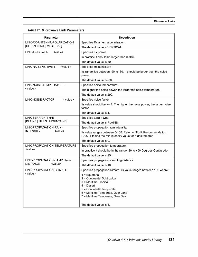
Microwave Links
LINK-RX-ANTENNA-POLARIZATION [HORIZONTAL | VERTICAL]
Specifies Rx antenna polarization.
The default value is VERTICAL.
LINK-TX-POWER <value> Specifies Tx power.
In practice it should be larger than 0 dBm.
The default value is 30.
LINK-RX-SENSITIVITY <value> Specifies Rx sensitivity.
Its range lies between -90 to -60. It should be larger than the noise power.
The default value is -80.
LINK-NOISE-TEMPERATURE <value>
Specifies noise temperature.
The higher the noise power, the larger the noise temperature.
The default value is 290.
LINK-NOISE-FACTOR <value> Specifies noise factor.
Its value should be >= 1. The higher the noise power, the larger noise factor.
The default value is 4.
LINK-TERRAIN-TYPE [PLAINS | HILLS | MOUNTAINS]
Specifies terrain type.
The default value is PLAINS.
LINK-PROPAGATION-RAIN-INTENSITY <value>
Specifies propagation rain intensity.
Its value ranges between 0-100. Refer to ITU-R Recommendation P.837-1 to find the rain intensity value for a desired area.
The default value is 0.
LINK-PROPAGATION-TEMPERATURE <value>
Specifies propagation temperature.
In practice it should be in the range -20 to +50 Degrees Centigrade.
The default value is 25.
LINK-PROPAGATION-SAMPLING-DISTANCE <value>
Specifies propagation sampling distance.
The default value is 100.
LINK-PROPAGATION-CLIMATE <value>
Specifies propagation climate. Its value ranges between 1-7, where:
1 = Equatorial 2 = Continental Subtropical3 = Maritime Tropical4 = Desert5 = Continental Temperate6 = Maritime Temperate, Over Land7 = Maritime Temperate, Over Sea
The default value is 1.
TABLE 67. Microwave Link Parameters
Parameter Description
QualNet 4.5.1 Wireless Model Library 135
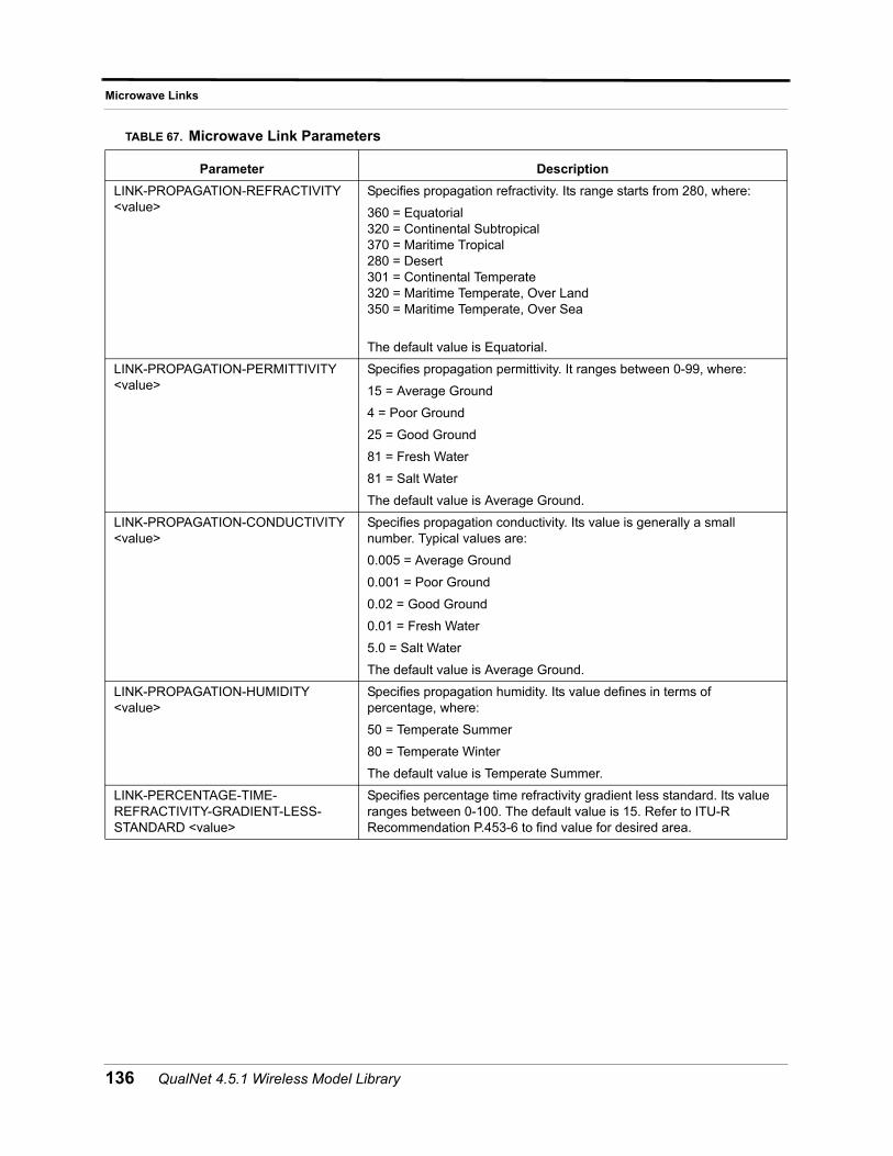
Microwave Links
LINK-PROPAGATION-REFRACTIVITY <value>
Specifies propagation refractivity. Its range starts from 280, where:
360 = Equatorial320 = Continental Subtropical370 = Maritime Tropical280 = Desert301 = Continental Temperate320 = Maritime Temperate, Over Land350 = Maritime Temperate, Over Sea
The default value is Equatorial.
LINK-PROPAGATION-PERMITTIVITY <value>
Specifies propagation permittivity. It ranges between 0-99, where:
15 = Average Ground
4 = Poor Ground
25 = Good Ground
81 = Fresh Water
81 = Salt Water
The default value is Average Ground.
LINK-PROPAGATION-CONDUCTIVITY <value>
Specifies propagation conductivity. Its value is generally a small number. Typical values are:
0.005 = Average Ground
0.001 = Poor Ground
0.02 = Good Ground
0.01 = Fresh Water
5.0 = Salt Water
The default value is Average Ground.
LINK-PROPAGATION-HUMIDITY <value>
Specifies propagation humidity. Its value defines in terms of percentage, where:
50 = Temperate Summer
80 = Temperate Winter
The default value is Temperate Summer.
LINK-PERCENTAGE-TIME-REFRACTIVITY-GRADIENT-LESS-STANDARD <value>
Specifies percentage time refractivity gradient less standard. Its value ranges between 0-100. The default value is 15. Refer to ITU-R Recommendation P.453-6 to find value for desired area.
TABLE 67. Microwave Link Parameters
Parameter Description
136 QualNet 4.5.1 Wireless Model Library
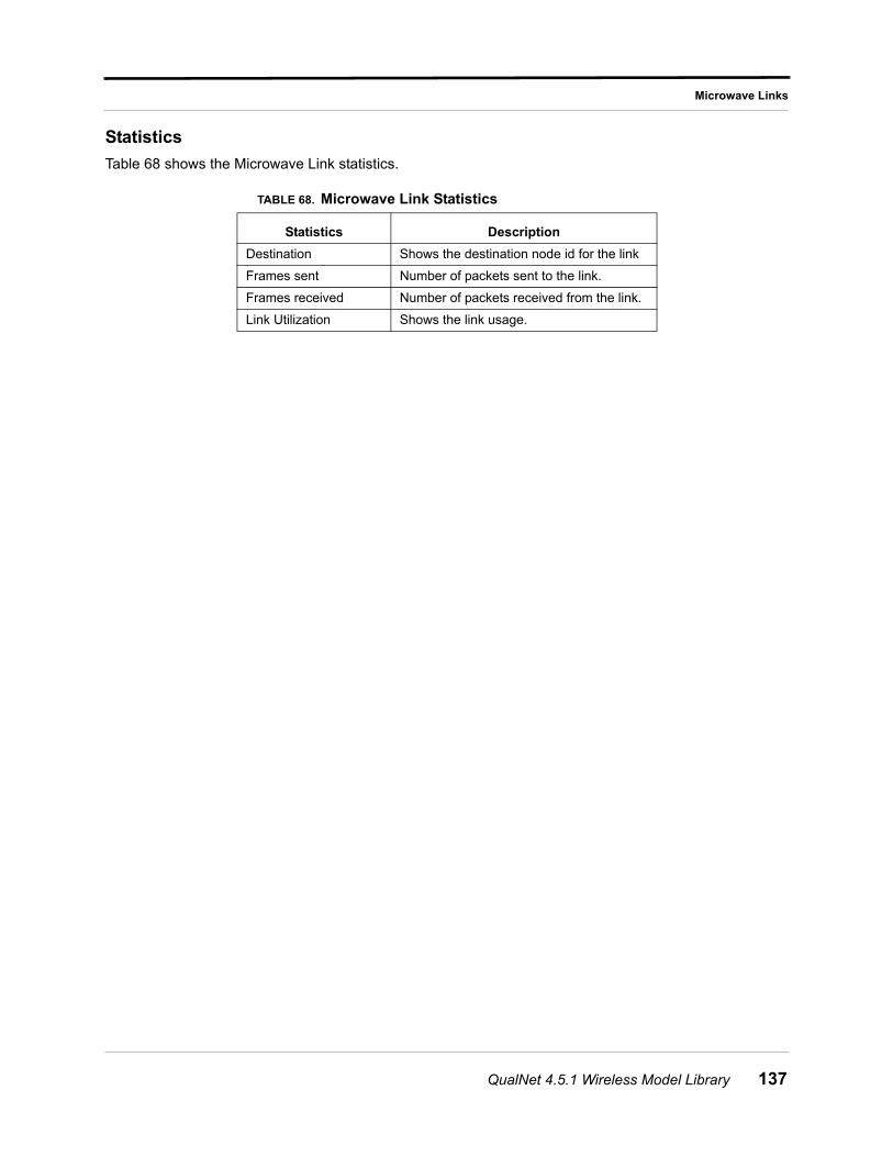
Microwave Links
Statistics
Table 68 shows the Microwave Link statistics.
TABLE 68. Microwave Link Statistics
Statistics Description
Destination Shows the destination node id for the link
Frames sent Number of packets sent to the link.
Frames received Number of packets received from the link.
Link Utilization Shows the link usage.
QualNet 4.5.1 Wireless Model Library 137
Mobile IPv4
Mobile IPv4
Mobile nodes were not considered when the Internet Protocol (IPv4) was designed. Then and now, a node's IP address, which indicates its point of attachment to the Internet, is assumed to remain unchanged for the duration of a session. Mobile IP, a standard proposed by the Internet Engineering Task Force (IETF), was designed to solve this problem by allowing the mobile node to use two IP addresses: a fixed Home Address and a Care-of Address (COA) that changes at each new point of attachment to the Internet.
Mobility Support for IPv4 defines a protocol that allows transparent routing of IP datagrams to Mobile Nodes as they move about from one domain to another on the Internet. When a Mobile Node moves into a foreign network, its computing activities are not disrupted. Instead, all the needed reconnection occurs automatically and without user interaction. Each mobile node is always identified by its home address, which is static regardless of its current point of attachment to the Internet. While situated away from its home agent, a mobile node is also associated with a care-of-address, which provides information about its current point of attachment to the Internet. When the mobile node is attached to the home network, it operates without any mobility support. Whenever the mobile node is not attached to its home network (and is therefore attached to any foreign network), the home agent gets all the packets destined for the mobile node and arranges to deliver them to the mobile node's current point of attachment. The home agent sends datagrams destined for the mobile node through a tunnel to the care-of-address. After arriving at the end of the tunnel, each datagram is then delivered to the mobile node. The mobile IP protocol provides for registering the care-of address with a home agent.
Command Line Configuration
To run mobile IPv4 with QualNet, you must provide input information through the *.config file. The following parameters describe the configuration for mobile IP in the *.config file.
1. This version of mobile IPv4 supports only OSPFv2 as the network Routing Protocol and MAC 802.11 as the MAC protocol. The mobile node has no routing capability. You must use the following configuration:
ROUTING-PROTOCOL OSPFv2MAC-PROTOCOL MAC802.11
2. The mobility of mobile nodes must be defined using the mobility trace file. You must use the following configuration:
MOBILTITY FILE MOBILITY-PLACEMENT FILENODE-POSITION-FILE ./<experiment_name>.nodes
3. Every mobile agent should be an Internet Control Message Protocol (ICMP) router for running router discovery process. You must use the following configuration:
ICMP YESICMP-ROUTER-DISCOVERY YESICMP-ROUTER-LIST {<4, 5node id list>}
4. The mobile node, home and foreign agents for every Mobile IPv4 network must be configured using the parameters shown in Table 69.
138 QualNet 4.5.1 Wireless Model Library
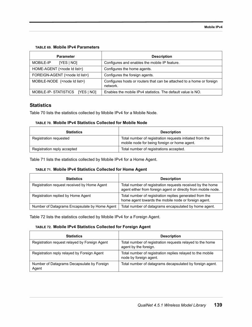
Mobile IPv4
Statistics
Table 70 lists the statistics collected by Mobile IPv4 for a Mobile Node.
Table 71 lists the statistics collected by Mobile IPv4 for a Home Agent.
Table 72 lists the statistics collected by Mobile IPv4 for a Foreign Agent.
TABLE 69. Mobile IPv4 Parameters
Parameter Description
MOBILE-IP [YES | NO] Configures and enables the mobile IP feature.
HOME-AGENT {<node Id list>} Configures the home agents.
FOREIGN-AGENT {<node Id list>} Configures the foreign agents.
MOBILE-NODE {<node Id list>} Configures hosts or routers that can be attached to a home or foreign network.
MOBILE-IP- STATISTICS [YES | NO] Enables the mobile IPv4 statistics. The default value is NO.
TABLE 70. Mobile IPv4 Statistics Collected for Mobile Node
Statistics Description
Registration requested Total number of registration requests initiated from the mobile node for being foreign or home agent.
Registration reply accepted Total number of registrations accepted.
TABLE 71. Mobile IPv4 Statistics Collected for Home Agent
Statistics Description
Registration request received by Home Agent Total number of registration requests received by the home agent either from foreign agent or directly from mobile node.
Registration replied by Home Agent Total number of registration replies generated from the home agent towards the mobile node or foreign agent.
Number of Datagrams Encapsulate by Home Agent Total number of datagrams encapsulated by home agent.
TABLE 72. Mobile IPv4 Statistics Collected for Foreign Agent
Statistics Description
Registration request relayed by Foreign Agent Total number of registration requests relayed to the home agent by the foreign.
Registration reply relayed by Foreign Agent Total number of registration replies relayed to the mobile node by foreign agent.
Number of Datagrams Decapsulate by Foreign Agent
Total number of datagrams decapsulated by foreign agent.
QualNet 4.5.1 Wireless Model Library 139
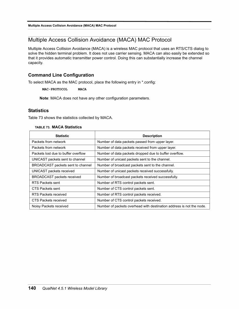
Multiple Access Collision Avoidance (MACA) MAC Protocol
Multiple Access Collision Avoidance (MACA) MAC Protocol
Multiple Access Collision Avoidance (MACA) is a wireless MAC protocol that uses an RTS/CTS dialog to solve the hidden terminal problem. It does not use carrier sensing. MACA can also easily be extended so that it provides automatic transmitter power control. Doing this can substantially increase the channel capacity.
Command Line Configuration
To select MACA as the MAC protocol, place the following entry in *.config:
MAC-PROTOCOL MACA
Note: MACA does not have any other configuration parameters.
Statistics
Table 73 shows the statistics collected by MACA.
TABLE 73. MACA Statistics
Statistic Description
Packets from network Number of data packets passed from upper layer.
Packets from network Number of data packets received from upper layer.
Packets lost due to buffer overflow Number of data packets dropped due to buffer overflow.
UNICAST packets sent to channel Number of unicast packets sent to the channel.
BROADCAST packets sent to channel Number of broadcast packets sent to the channel.
UNICAST packets received Number of unicast packets received successfully.
BROADCAST packets received Number of broadcast packets received successfully.
RTS Packets sent Number of RTS control packets sent.
CTS Packets sent Number of CTS control packets sent.
RTS Packets received Number of RTS control packets received.
CTS Packets received Number of CTS control packets received.
Noisy Packets received Number of packets overhead with destination address is not the node.
140 QualNet 4.5.1 Wireless Model Library
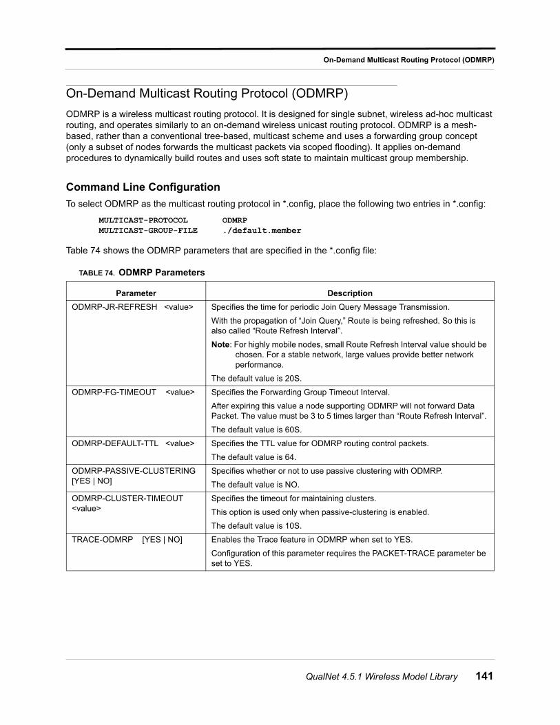
On-Demand Multicast Routing Protocol (ODMRP)
On-Demand Multicast Routing Protocol (ODMRP)
ODMRP is a wireless multicast routing protocol. It is designed for single subnet, wireless ad-hoc multicast routing, and operates similarly to an on-demand wireless unicast routing protocol. ODMRP is a mesh-based, rather than a conventional tree-based, multicast scheme and uses a forwarding group concept (only a subset of nodes forwards the multicast packets via scoped flooding). It applies on-demand procedures to dynamically build routes and uses soft state to maintain multicast group membership.
Command Line Configuration
To select ODMRP as the multicast routing protocol in *.config, place the following two entries in *.config:
MULTICAST-PROTOCOL ODMRPMULTICAST-GROUP-FILE ./default.member
Table 74 shows the ODMRP parameters that are specified in the *.config file:
TABLE 74. ODMRP Parameters
Parameter Description
ODMRP-JR-REFRESH <value> Specifies the time for periodic Join Query Message Transmission.
With the propagation of “Join Query,” Route is being refreshed. So this is also called “Route Refresh Interval”.
Note: For highly mobile nodes, small Route Refresh Interval value should be chosen. For a stable network, large values provide better network performance.
The default value is 20S.
ODMRP-FG-TIMEOUT <value> Specifies the Forwarding Group Timeout Interval.
After expiring this value a node supporting ODMRP will not forward Data Packet. The value must be 3 to 5 times larger than “Route Refresh Interval”.
The default value is 60S.
ODMRP-DEFAULT-TTL <value> Specifies the TTL value for ODMRP routing control packets.
The default value is 64.
ODMRP-PASSIVE-CLUSTERING [YES | NO]
Specifies whether or not to use passive clustering with ODMRP.
The default value is NO.
ODMRP-CLUSTER-TIMEOUT <value>
Specifies the timeout for maintaining clusters.
This option is used only when passive-clustering is enabled.
The default value is 10S.
TRACE-ODMRP [YES | NO] Enables the Trace feature in ODMRP when set to YES.
Configuration of this parameter requires the PACKET-TRACE parameter be set to YES.
QualNet 4.5.1 Wireless Model Library 141
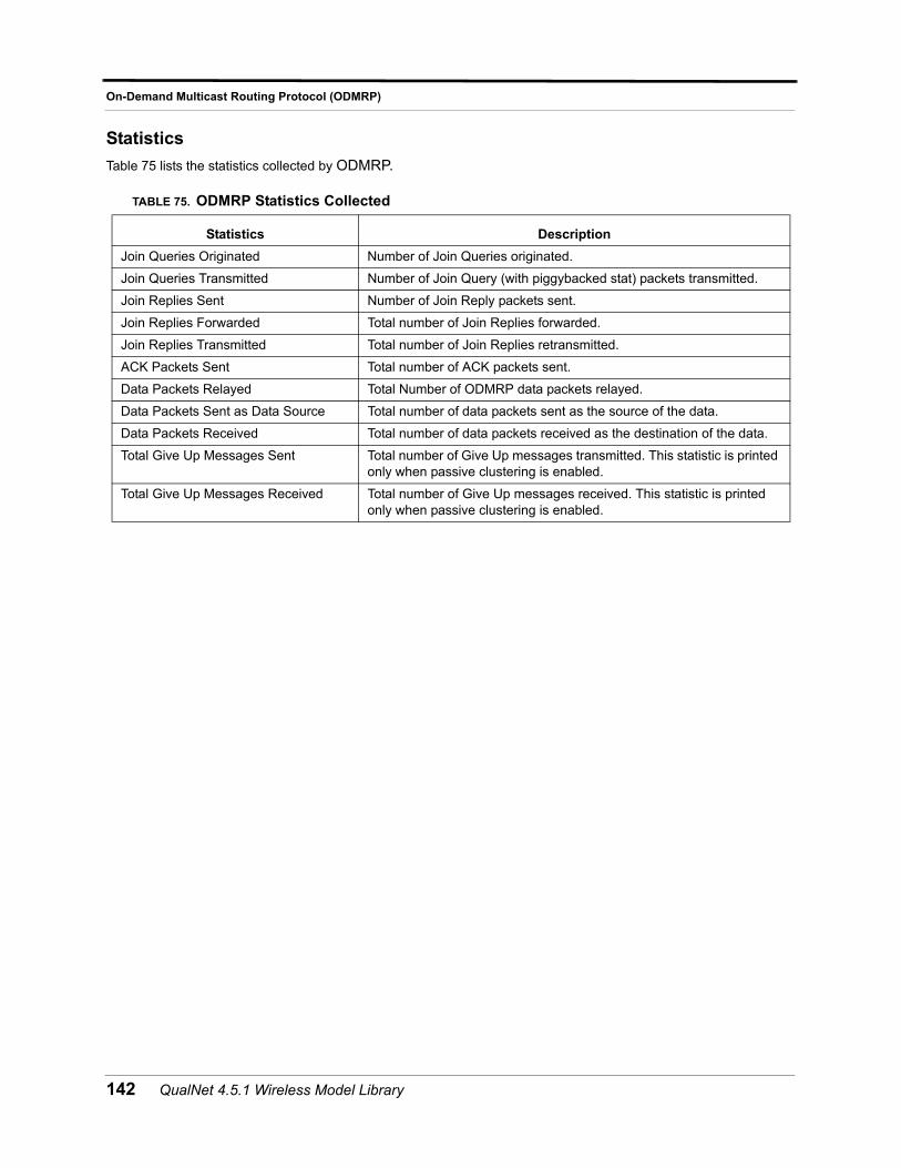
On-Demand Multicast Routing Protocol (ODMRP)
Statistics
Table 75 lists the statistics collected by ODMRP.
TABLE 75. ODMRP Statistics Collected
Statistics Description
Join Queries Originated Number of Join Queries originated.
Join Queries Transmitted Number of Join Query (with piggybacked stat) packets transmitted.
Join Replies Sent Number of Join Reply packets sent.
Join Replies Forwarded Total number of Join Replies forwarded.
Join Replies Transmitted Total number of Join Replies retransmitted.
ACK Packets Sent Total number of ACK packets sent.
Data Packets Relayed Total Number of ODMRP data packets relayed.
Data Packets Sent as Data Source Total number of data packets sent as the source of the data.
Data Packets Received Total number of data packets received as the destination of the data.
Total Give Up Messages Sent Total number of Give Up messages transmitted. This statistic is printed only when passive clustering is enabled.
Total Give Up Messages Received Total number of Give Up messages received. This statistic is printed only when passive clustering is enabled.
142 QualNet 4.5.1 Wireless Model Library
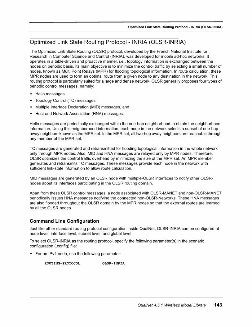
Optimized Link State Routing Protocol - INRIA (OLSR-INRIA)
Optimized Link State Routing Protocol - INRIA (OLSR-INRIA)
The Optimized Link State Routing (OLSR) protocol, developed by the French National Institute for Research in Computer Science and Control (INRIA), was developed for mobile ad-hoc networks. It operates in a table-driven and proactive manner, i.e., topology information is exchanged between the nodes on periodic basis. Its main objective is to minimize the control traffic by selecting a small number of nodes, known as Multi Point Relays (MPR) for flooding topological information. In route calculation, these MPR nodes are used to form an optimal route from a given node to any destination in the network. This routing protocol is particularly suited for a large and dense network. OLSR generally proposes four types of periodic control messages, namely:
• Hello messages
• Topology Control (TC) messages
• Multiple Interface Declaration (MID) messages, and
• Host and Network Association (HNA) messages.
Hello messages are periodically exchanged within the one-hop neighborhood to obtain the neighborhood information. Using this neighborhood information, each node in the network selects a subset of one-hop away neighbors known as the MPR set. In the MPR set, all two-hop away neighbors are reachable through any member of the MPR set.
TC messages are generated and retransmitted for flooding topological information in the whole network only through MPR nodes. Also, MID and HNA messages are relayed only by MPR nodes. Therefore, OLSR optimizes the control traffic overhead by minimizing the size of the MPR set. An MPR member generates and retransmits TC messages. These messages provide each node in the network with sufficient link-state information to allow route calculation.
MID messages are generated by an OLSR node with multiple-OLSR interfaces to notify other OLSR-nodes about its interfaces participating in the OLSR routing domain.
Apart from these OLSR control messages, a node associated with OLSR-MANET and non-OLSR-MANET periodically issues HNA messages notifying the connected non-OLSR-Networks. These HNA messages are also flooded throughout the OLSR domain by the MPR nodes so that the external routes are learned by all the OLSR nodes.
Command Line Configuration
Just like other standard routing protocol configuration inside QualNet, OLSR-INRIA can be configured at node level, interface level, subnet level, and global level.
To select OLSR-INRIA as the routing protocol, specify the following parameter(s) in the scenario configuration (.config) file:
• For an IPv4 node, use the following parameter:
ROUTING-PROTOCOL OLSR-INRIA
QualNet 4.5.1 Wireless Model Library 143
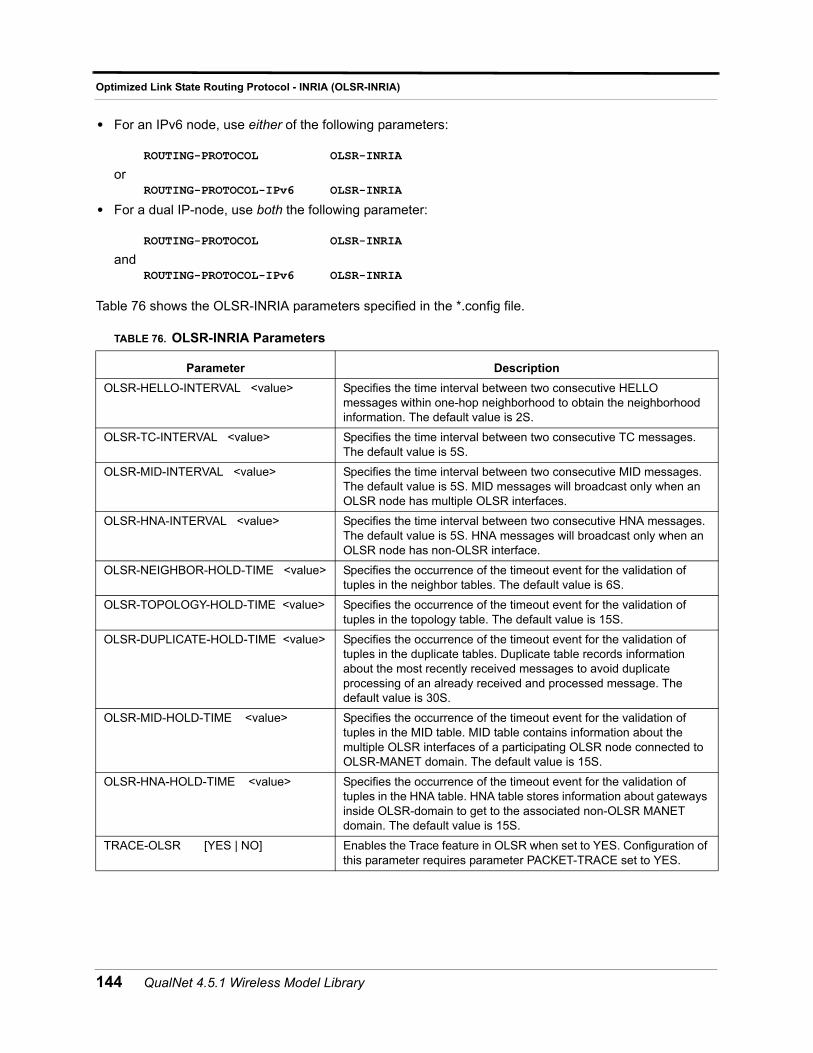
Optimized Link State Routing Protocol - INRIA (OLSR-INRIA)
• For an IPv6 node, use either of the following parameters:
ROUTING-PROTOCOL OLSR-INRIA
orROUTING-PROTOCOL-IPv6 OLSR-INRIA
• For a dual IP-node, use both the following parameter:
ROUTING-PROTOCOL OLSR-INRIA
andROUTING-PROTOCOL-IPv6 OLSR-INRIA
Table 76 shows the OLSR-INRIA parameters specified in the *.config file.
TABLE 76. OLSR-INRIA Parameters
Parameter Description
OLSR-HELLO-INTERVAL <value> Specifies the time interval between two consecutive HELLO messages within one-hop neighborhood to obtain the neighborhood information. The default value is 2S.
OLSR-TC-INTERVAL <value> Specifies the time interval between two consecutive TC messages. The default value is 5S.
OLSR-MID-INTERVAL <value> Specifies the time interval between two consecutive MID messages. The default value is 5S. MID messages will broadcast only when an OLSR node has multiple OLSR interfaces.
OLSR-HNA-INTERVAL <value> Specifies the time interval between two consecutive HNA messages. The default value is 5S. HNA messages will broadcast only when an OLSR node has non-OLSR interface.
OLSR-NEIGHBOR-HOLD-TIME <value> Specifies the occurrence of the timeout event for the validation of tuples in the neighbor tables. The default value is 6S.
OLSR-TOPOLOGY-HOLD-TIME <value> Specifies the occurrence of the timeout event for the validation of tuples in the topology table. The default value is 15S.
OLSR-DUPLICATE-HOLD-TIME <value> Specifies the occurrence of the timeout event for the validation of tuples in the duplicate tables. Duplicate table records information about the most recently received messages to avoid duplicate processing of an already received and processed message. The default value is 30S.
OLSR-MID-HOLD-TIME <value> Specifies the occurrence of the timeout event for the validation of tuples in the MID table. MID table contains information about the multiple OLSR interfaces of a participating OLSR node connected to OLSR-MANET domain. The default value is 15S.
OLSR-HNA-HOLD-TIME <value> Specifies the occurrence of the timeout event for the validation of tuples in the HNA table. HNA table stores information about gateways inside OLSR-domain to get to the associated non-OLSR MANET domain. The default value is 15S.
TRACE-OLSR [YES | NO] Enables the Trace feature in OLSR when set to YES. Configuration of this parameter requires parameter PACKET-TRACE set to YES.
144 QualNet 4.5.1 Wireless Model Library
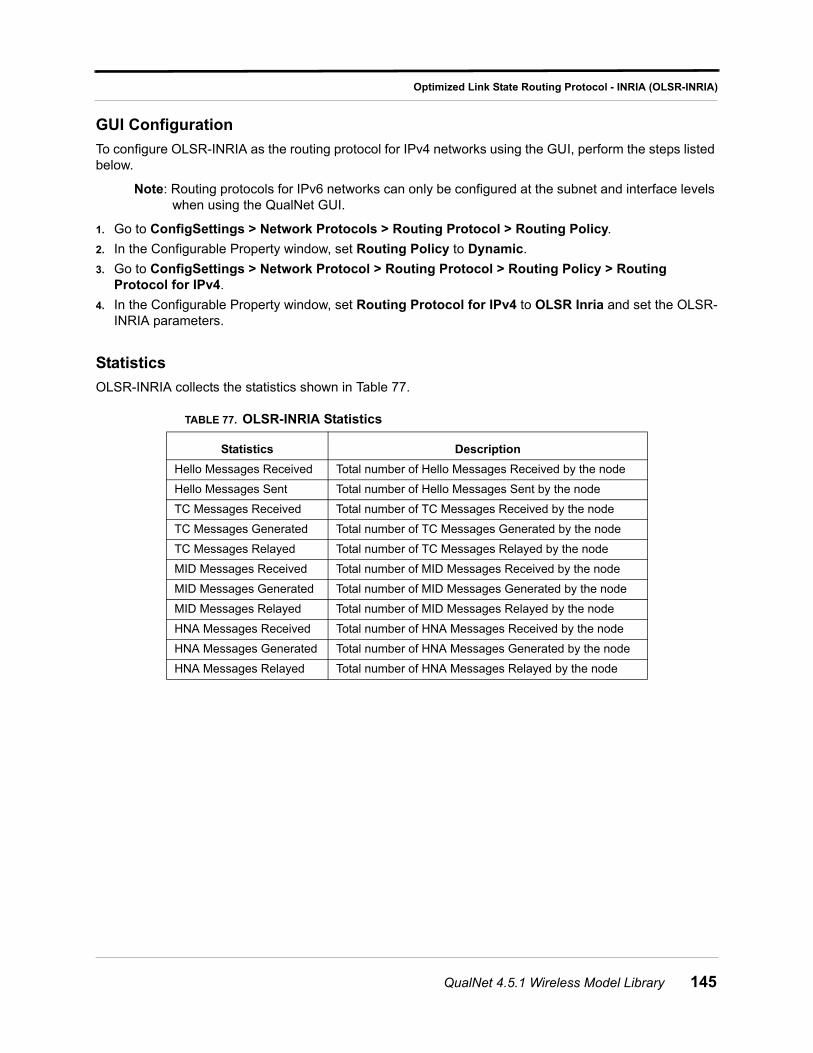
Optimized Link State Routing Protocol - INRIA (OLSR-INRIA)
GUI Configuration
To configure OLSR-INRIA as the routing protocol for IPv4 networks using the GUI, perform the steps listed below.
Note: Routing protocols for IPv6 networks can only be configured at the subnet and interface levels when using the QualNet GUI.
1. Go to ConfigSettings > Network Protocols > Routing Protocol > Routing Policy.
2. In the Configurable Property window, set Routing Policy to Dynamic.
3. Go to ConfigSettings > Network Protocol > Routing Protocol > Routing Policy > Routing Protocol for IPv4.
4. In the Configurable Property window, set Routing Protocol for IPv4 to OLSR Inria and set the OLSR-INRIA parameters.
Statistics
OLSR-INRIA collects the statistics shown in Table 77.
TABLE 77. OLSR-INRIA Statistics
Statistics Description
Hello Messages Received Total number of Hello Messages Received by the node
Hello Messages Sent Total number of Hello Messages Sent by the node
TC Messages Received Total number of TC Messages Received by the node
TC Messages Generated Total number of TC Messages Generated by the node
TC Messages Relayed Total number of TC Messages Relayed by the node
MID Messages Received Total number of MID Messages Received by the node
MID Messages Generated Total number of MID Messages Generated by the node
MID Messages Relayed Total number of MID Messages Relayed by the node
HNA Messages Received Total number of HNA Messages Received by the node
HNA Messages Generated Total number of HNA Messages Generated by the node
HNA Messages Relayed Total number of HNA Messages Relayed by the node
QualNet 4.5.1 Wireless Model Library 145
Optimized Link State Routing Protocol version 2 (OLSRv2)
Optimized Link State Routing Protocol version 2 (OLSRv2)
OLSRv2 is an update to OLSRv1 as published in RFC3626 [1]. Compared to RFC3626, OLSRv2 retains the same basic mechanisms and algorithms, while providing an even more flexible signaling framework and some simplification of the messages being exchanged. Also, OLSRv2 accommodates both IPv4 and IPv6 addresses in a compact fashion.
OLSRv2 is developed for mobile ad hoc networks. It operates as a table driven, proactive protocol, i.e. it exchanges topology information with other nodes of the network regularly. Each node selects a set of its neighbor nodes as "Multi Point Relays" (MPRs). Only nodes that are selected as such MPRs are then responsible for forwarding control traffic intended for diffusion into the entire network. MPRs provide an efficient mechanism for flooding control traffic by reducing the number of transmissions required.
Nodes selected as MPRs also have a special responsibility when declaring link state information in the network. Indeed, the only requirement for OLSRv2 to provide shortest path routes to all destinations is that MPR nodes declare link-state information for their MPR selectors. Additional available link-state information may be utilized, e.g. for redundancy. Nodes that have been selected as multipoint relays by some neighbor node(s) announce this information periodically in their control messages. Thereby a node announces to the network that it has reachability to the nodes which have selected it as an MPR. Thus, as well as being used to facilitate efficient flooding, MPRs are also used for route calculation from any given node to any destination in the network.
A node selects MPRs from among its one hop neighbors with "symmetric", i.e. bi-directional, linkages. Therefore, selecting routes through MPRs automatically avoids the problems associated with data packet transfer over unit-directional links (such as the problem of not getting link-layer acknowledgments for data packets at each hop, for link-layers employing this technique for unicast traffic).
OLSRv2 is developed to work independently from other protocols. Likewise, OLSRv2 makes no assumptions about the underlying link-layer. However, OLSRv2 may use link-layer information and notifications when available and applicable.
It uses mainly two basic types of control packets as stated below
• Hello Messages: HELLO messages in OLSRv2 serve to:
• discover links to adjacent OLSR nodes;
• perform bidirectional check on the discovered links;
• advertise neighbors and hence discover 2-hop neighbors;
• signal MPR selection.
• advertise own interfaces which participate in MANET
HELLO messages are emitted periodically, thereby allowing nodes to continuously track changes in their local neighborhoods.
OLSRv2 applies Neighborhood discovery protocol for HELLO messages to continuously update information repositories describing the node's 1-hop and 2-hop neighbors. Neighborhood discovery protocol using HELLO messages uses generic multi-message packet format, for carrying MANET routing protocol signals.
• TC messages (Topology Control messages) in OLSRv2 serve to:
• inject link-state information into the entire network;
146 QualNet 4.5.1 Wireless Model Library
Optimized Link State Routing Protocol version 2 (OLSRv2)
• inject addresses of hosts and networks for which they may serve as a gateway into the entire network.
• allow nodes with multiple interface addresses to ensure that nodes within two hops can associate these addresses with a single node for efficient MPR Set determination.
TC messages are emitted periodically, thereby allowing nodes to continuously track global changes in the network. A TC message must contain:
• a message TLV VALIDITY_TIME
• a message TLV CONTENT_SEQUENCE_NUMBER
• one or more address blocks with associated address block TLVs.
The first (mandatory) address block is a Local Interface Block. Other (optional) address blocks contain 1-hop neighbors' interface addresses and/or host or network addresses for which this node may act as a gateway. In the latter case they may use PREFIX_LENGTH TLV(s) and must attach GATEWAY TLV(s).
The purpose of OLSRv2 is to determine the Routing Set, which may be used to update IP's Routing Table, providing "next hop" routing information for IP datagrams. In order to accomplish this, OLSRv2 uses a number of protocol sets:
• Neighborhood Information Base: The neighborhood information base stores information about links between local interfaces and interfaces on adjacent nodes.
• Topology Information Base: The Topology Information Base stores information, required for the generation and processing of TC messages.
Command Line Configuration
To select OLSR-INRIA as the routing protocol, specify the following parameter(s) in the scenario configuration (.config) file:
• For an IPv4 node, use the following parameter:
ROUTING-PROTOCOL OLSRv2-NIIGATA
• For an IPv6 node, use either of the following parameters:
ROUTING-PROTOCOL OLSRv2-NIIGATA
orROUTING-PROTOCOL-IPv6 OLSRv2-NIIGATA
• For a dual IP-node, use both the following parameter:
ROUTING-PROTOCOL OLSRv2-NIIGATA
andROUTING-PROTOCOL-IPv6 OLSRv2-NIIGATA
QualNet 4.5.1 Wireless Model Library 147
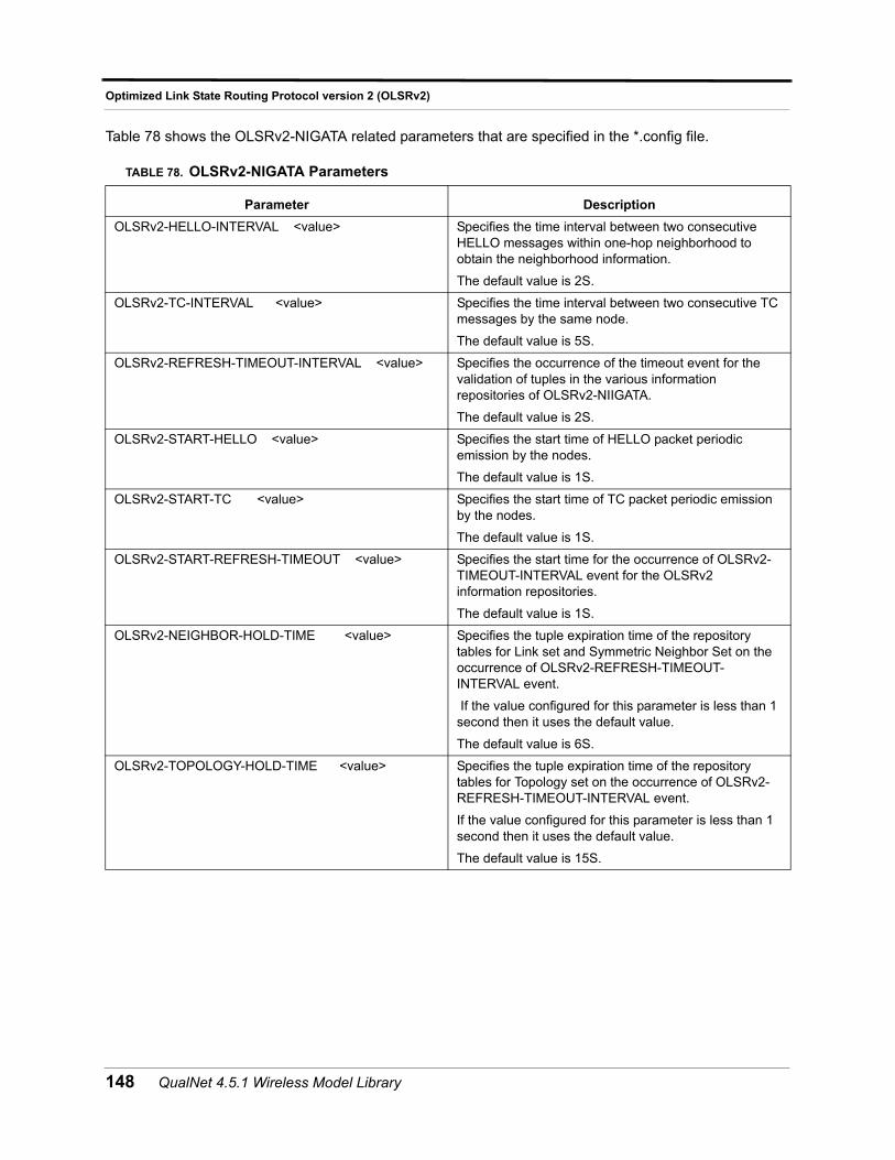
Optimized Link State Routing Protocol version 2 (OLSRv2)
Table 78 shows the OLSRv2-NIGATA related parameters that are specified in the *.config file.
TABLE 78. OLSRv2-NIGATA Parameters
Parameter Description
OLSRv2-HELLO-INTERVAL <value> Specifies the time interval between two consecutive HELLO messages within one-hop neighborhood to obtain the neighborhood information.
The default value is 2S.
OLSRv2-TC-INTERVAL <value> Specifies the time interval between two consecutive TC messages by the same node.
The default value is 5S.
OLSRv2-REFRESH-TIMEOUT-INTERVAL <value> Specifies the occurrence of the timeout event for the validation of tuples in the various information repositories of OLSRv2-NIIGATA.
The default value is 2S.
OLSRv2-START-HELLO <value> Specifies the start time of HELLO packet periodic emission by the nodes.
The default value is 1S.
OLSRv2-START-TC <value> Specifies the start time of TC packet periodic emission by the nodes.
The default value is 1S.
OLSRv2-START-REFRESH-TIMEOUT <value> Specifies the start time for the occurrence of OLSRv2-TIMEOUT-INTERVAL event for the OLSRv2 information repositories.
The default value is 1S.
OLSRv2-NEIGHBOR-HOLD-TIME <value> Specifies the tuple expiration time of the repository tables for Link set and Symmetric Neighbor Set on the occurrence of OLSRv2-REFRESH-TIMEOUT-INTERVAL event.
If the value configured for this parameter is less than 1 second then it uses the default value.
The default value is 6S.
OLSRv2-TOPOLOGY-HOLD-TIME <value> Specifies the tuple expiration time of the repository tables for Topology set on the occurrence of OLSRv2-REFRESH-TIMEOUT-INTERVAL event.
If the value configured for this parameter is less than 1 second then it uses the default value.
The default value is 15S.
148 QualNet 4.5.1 Wireless Model Library
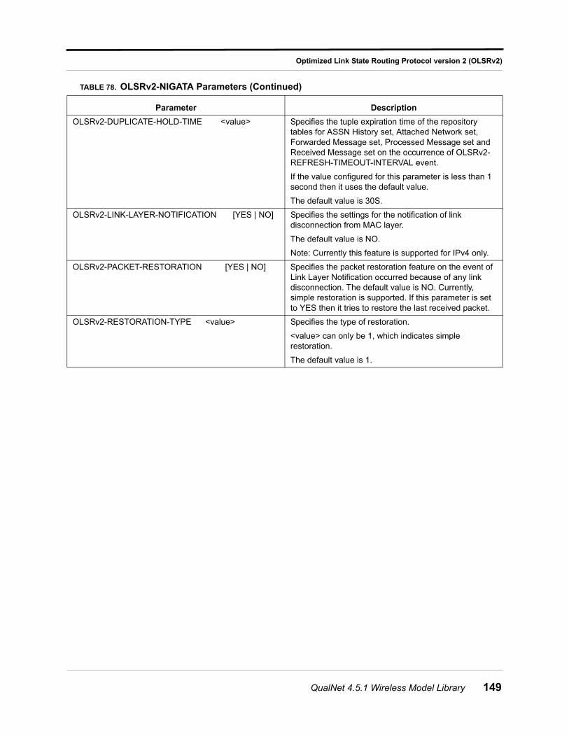
Optimized Link State Routing Protocol version 2 (OLSRv2)
OLSRv2-DUPLICATE-HOLD-TIME <value> Specifies the tuple expiration time of the repository tables for ASSN History set, Attached Network set, Forwarded Message set, Processed Message set and Received Message set on the occurrence of OLSRv2-REFRESH-TIMEOUT-INTERVAL event.
If the value configured for this parameter is less than 1 second then it uses the default value.
The default value is 30S.
OLSRv2-LINK-LAYER-NOTIFICATION [YES | NO] Specifies the settings for the notification of link disconnection from MAC layer.
The default value is NO.
Note: Currently this feature is supported for IPv4 only.
OLSRv2-PACKET-RESTORATION [YES | NO] Specifies the packet restoration feature on the event of Link Layer Notification occurred because of any link disconnection. The default value is NO. Currently, simple restoration is supported. If this parameter is set to YES then it tries to restore the last received packet.
OLSRv2-RESTORATION-TYPE <value> Specifies the type of restoration.
<value> can only be 1, which indicates simple restoration.
The default value is 1.
TABLE 78. OLSRv2-NIGATA Parameters (Continued)
Parameter Description
QualNet 4.5.1 Wireless Model Library 149
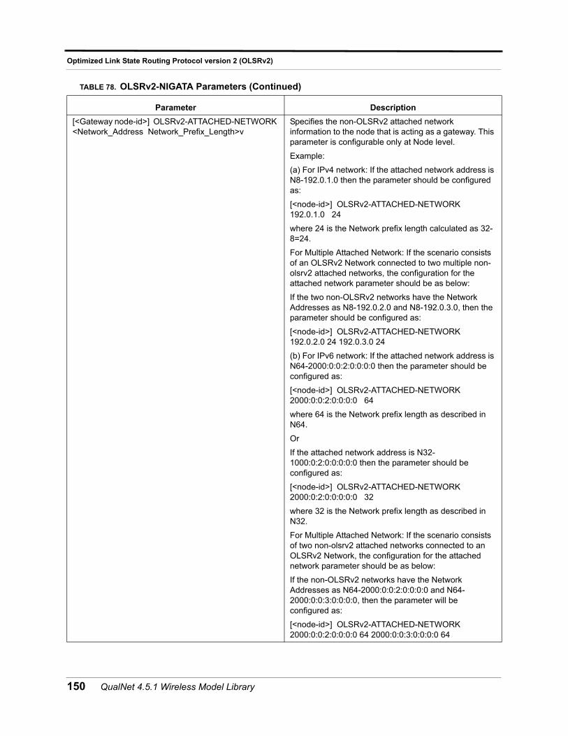
Optimized Link State Routing Protocol version 2 (OLSRv2)
[<Gateway node-id>] OLSRv2-ATTACHED-NETWORK <Network_Address Network_Prefix_Length>v
Specifies the non-OLSRv2 attached network information to the node that is acting as a gateway. This parameter is configurable only at Node level.
Example:
(a) For IPv4 network: If the attached network address is N8-192.0.1.0 then the parameter should be configured as:
[<node-id>] OLSRv2-ATTACHED-NETWORK 192.0.1.0 24
where 24 is the Network prefix length calculated as 32-8=24.
For Multiple Attached Network: If the scenario consists of an OLSRv2 Network connected to two multiple non-olsrv2 attached networks, the configuration for the attached network parameter should be as below:
If the two non-OLSRv2 networks have the Network Addresses as N8-192.0.2.0 and N8-192.0.3.0, then the parameter should be configured as:
[<node-id>] OLSRv2-ATTACHED-NETWORK 192.0.2.0 24 192.0.3.0 24
(b) For IPv6 network: If the attached network address is N64-2000:0:0:2:0:0:0:0 then the parameter should be configured as:
[<node-id>] OLSRv2-ATTACHED-NETWORK 2000:0:0:2:0:0:0:0 64
where 64 is the Network prefix length as described in N64.
Or
If the attached network address is N32-1000:0:2:0:0:0:0:0 then the parameter should be configured as:
[<node-id>] OLSRv2-ATTACHED-NETWORK 2000:0:2:0:0:0:0:0 32
where 32 is the Network prefix length as described in N32.
For Multiple Attached Network: If the scenario consists of two non-olsrv2 attached networks connected to an OLSRv2 Network, the configuration for the attached network parameter should be as below:
If the non-OLSRv2 networks have the Network Addresses as N64-2000:0:0:2:0:0:0:0 and N64-2000:0:0:3:0:0:0:0, then the parameter will be configured as:
[<node-id>] OLSRv2-ATTACHED-NETWORK 2000:0:0:2:0:0:0:0 64 2000:0:0:3:0:0:0:0 64
TABLE 78. OLSRv2-NIGATA Parameters (Continued)
Parameter Description
150 QualNet 4.5.1 Wireless Model Library
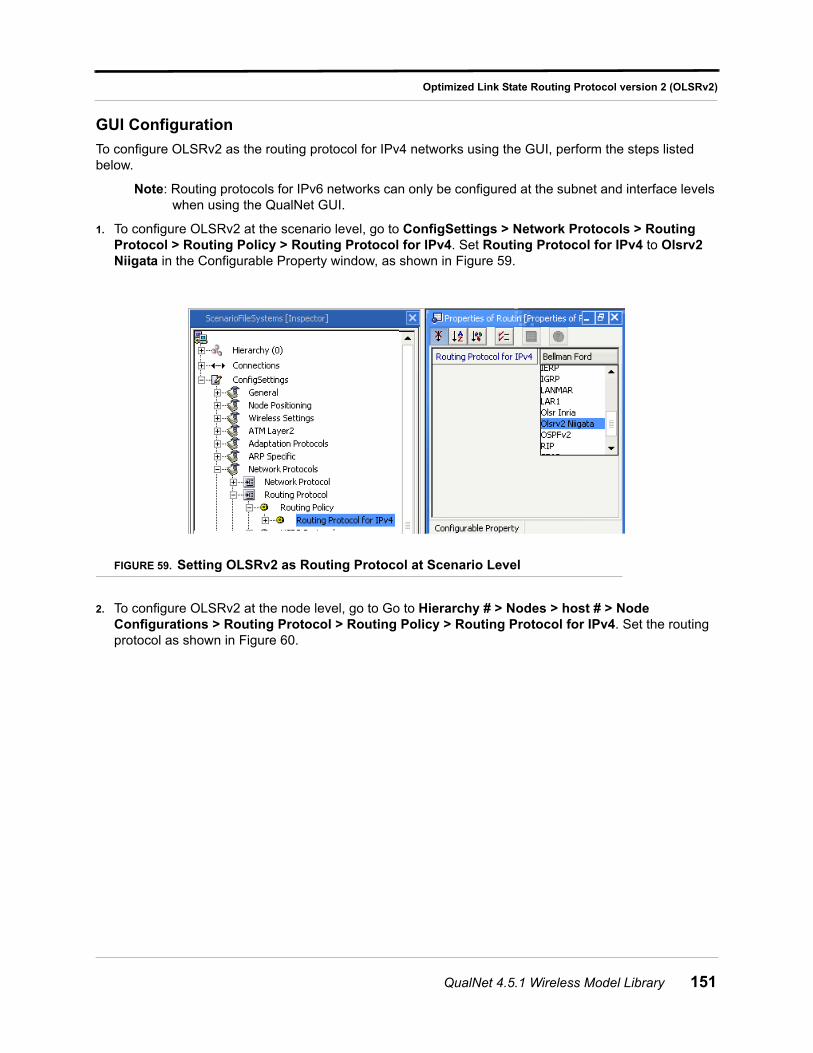
Optimized Link State Routing Protocol version 2 (OLSRv2)
GUI Configuration
To configure OLSRv2 as the routing protocol for IPv4 networks using the GUI, perform the steps listed below.
Note: Routing protocols for IPv6 networks can only be configured at the subnet and interface levels when using the QualNet GUI.
1. To configure OLSRv2 at the scenario level, go to ConfigSettings > Network Protocols > Routing Protocol > Routing Policy > Routing Protocol for IPv4. Set Routing Protocol for IPv4 to Olsrv2 Niigata in the Configurable Property window, as shown in Figure 59.
FIGURE 59. Setting OLSRv2 as Routing Protocol at Scenario Level
2. To configure OLSRv2 at the node level, go to Go to Hierarchy # > Nodes > host # > Node Configurations > Routing Protocol > Routing Policy > Routing Protocol for IPv4. Set the routing protocol as shown in Figure 60.
QualNet 4.5.1 Wireless Model Library 151
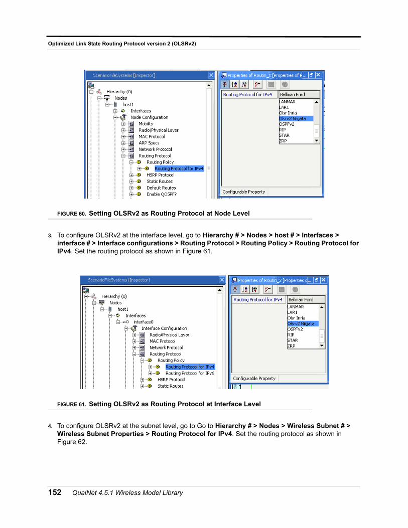
Optimized Link State Routing Protocol version 2 (OLSRv2)
FIGURE 60. Setting OLSRv2 as Routing Protocol at Node Level
3. To configure OLSRv2 at the interface level, go to Hierarchy # > Nodes > host # > Interfaces > interface # > Interface configurations > Routing Protocol > Routing Policy > Routing Protocol for IPv4. Set the routing protocol as shown in Figure 61.
FIGURE 61. Setting OLSRv2 as Routing Protocol at Interface Level
4. To configure OLSRv2 at the subnet level, go to Go to Hierarchy # > Nodes > Wireless Subnet # > Wireless Subnet Properties > Routing Protocol for IPv4. Set the routing protocol as shown in Figure 62.
152 QualNet 4.5.1 Wireless Model Library
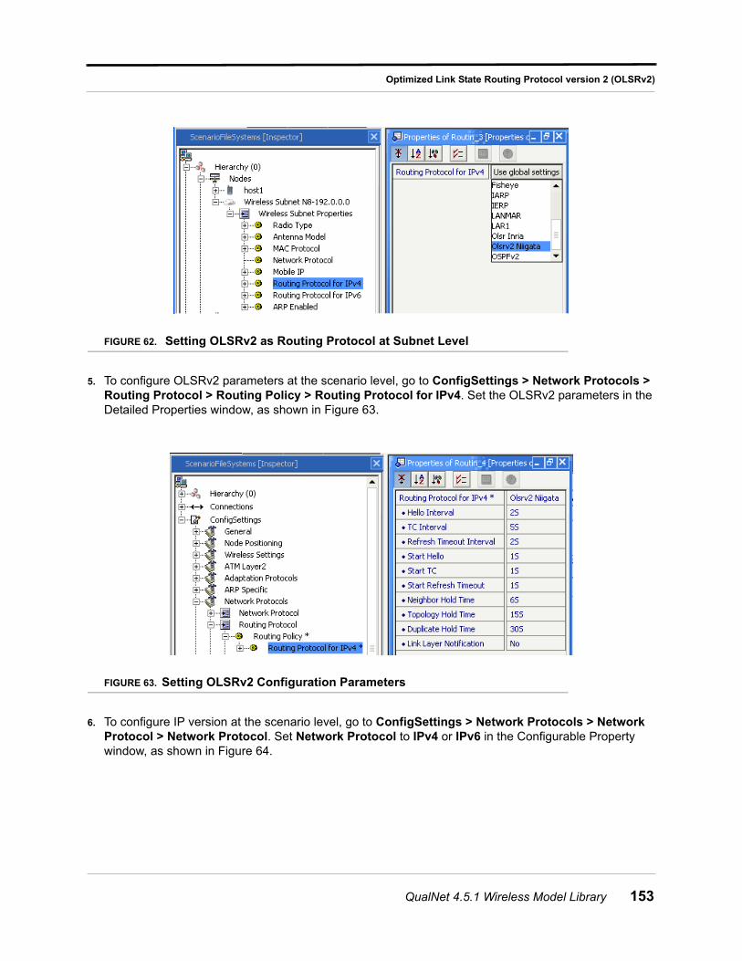
Optimized Link State Routing Protocol version 2 (OLSRv2)
FIGURE 62. Setting OLSRv2 as Routing Protocol at Subnet Level
5. To configure OLSRv2 parameters at the scenario level, go to ConfigSettings > Network Protocols > Routing Protocol > Routing Policy > Routing Protocol for IPv4. Set the OLSRv2 parameters in the Detailed Properties window, as shown in Figure 63.
FIGURE 63. Setting OLSRv2 Configuration Parameters
6. To configure IP version at the scenario level, go to ConfigSettings > Network Protocols > Network Protocol > Network Protocol. Set Network Protocol to IPv4 or IPv6 in the Configurable Property window, as shown in Figure 64.
QualNet 4.5.1 Wireless Model Library 153
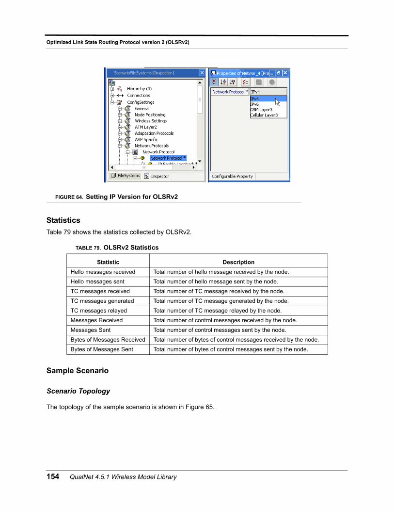
Optimized Link State Routing Protocol version 2 (OLSRv2)
FIGURE 64. Setting IP Version for OLSRv2
Statistics
Table 79 shows the statistics collected by OLSRv2.
Sample Scenario
Scenario Topology
The topology of the sample scenario is shown in Figure 65.
TABLE 79. OLSRv2 Statistics
Statistic Description
Hello messages received Total number of hello message received by the node.
Hello messages sent Total number of hello message sent by the node.
TC messages received Total number of TC message received by the node.
TC messages generated Total number of TC message generated by the node.
TC messages relayed Total number of TC message relayed by the node.
Messages Received Total number of control messages received by the node.
Messages Sent Total number of control messages sent by the node.
Bytes of Messages Received Total number of bytes of control messages received by the node.
Bytes of Messages Sent Total number of bytes of control messages sent by the node.
154 QualNet 4.5.1 Wireless Model Library
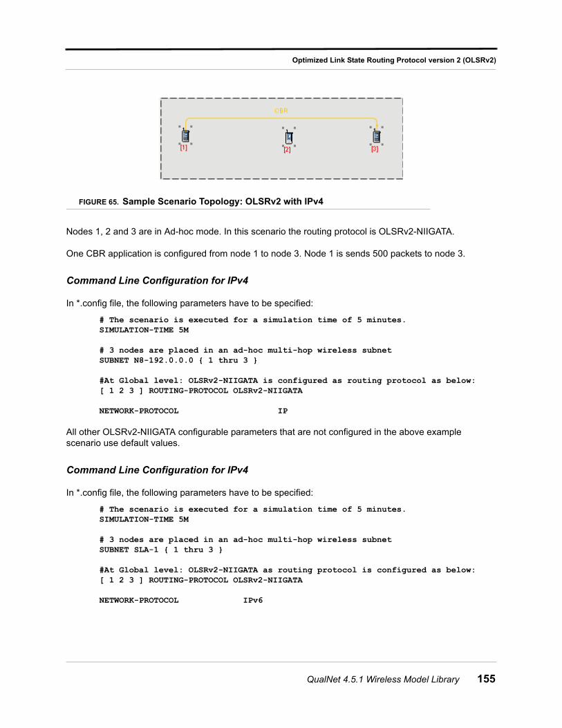
Optimized Link State Routing Protocol version 2 (OLSRv2)
FIGURE 65. Sample Scenario Topology: OLSRv2 with IPv4
Nodes 1, 2 and 3 are in Ad-hoc mode. In this scenario the routing protocol is OLSRv2-NIIGATA.
One CBR application is configured from node 1 to node 3. Node 1 is sends 500 packets to node 3.
Command Line Configuration for IPv4
In *.config file, the following parameters have to be specified:
# The scenario is executed for a simulation time of 5 minutes.SIMULATION-TIME 5M
# 3 nodes are placed in an ad-hoc multi-hop wireless subnetSUBNET N8-192.0.0.0 { 1 thru 3 }
#At Global level: OLSRv2-NIIGATA is configured as routing protocol as below: [ 1 2 3 ] ROUTING-PROTOCOL OLSRv2-NIIGATA
NETWORK-PROTOCOL IP
All other OLSRv2-NIIGATA configurable parameters that are not configured in the above example scenario use default values.
Command Line Configuration for IPv4
In *.config file, the following parameters have to be specified:
# The scenario is executed for a simulation time of 5 minutes.SIMULATION-TIME 5M
# 3 nodes are placed in an ad-hoc multi-hop wireless subnetSUBNET SLA-1 { 1 thru 3 }
#At Global level: OLSRv2-NIIGATA as routing protocol is configured as below: [ 1 2 3 ] ROUTING-PROTOCOL OLSRv2-NIIGATA
NETWORK-PROTOCOL IPv6
QualNet 4.5.1 Wireless Model Library 155
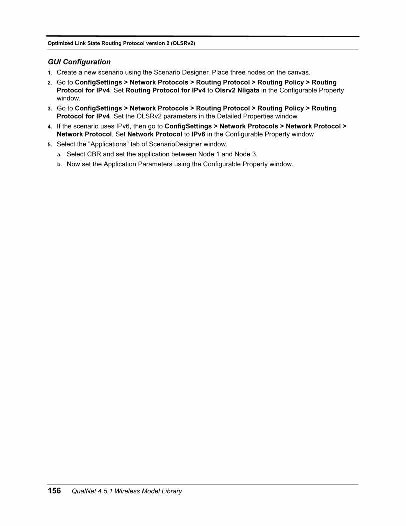
Optimized Link State Routing Protocol version 2 (OLSRv2)
GUI Configuration
1. Create a new scenario using the Scenario Designer. Place three nodes on the canvas.
2. Go to ConfigSettings > Network Protocols > Routing Protocol > Routing Policy > Routing Protocol for IPv4. Set Routing Protocol for IPv4 to Olsrv2 Niigata in the Configurable Property window.
3. Go to ConfigSettings > Network Protocols > Routing Protocol > Routing Policy > Routing Protocol for IPv4. Set the OLSRv2 parameters in the Detailed Properties window.
4. If the scenario uses IPv6, then go to ConfigSettings > Network Protocols > Network Protocol > Network Protocol. Set Network Protocol to IPv6 in the Configurable Property window
5. Select the "Applications" tab of ScenarioDesigner window.
a. Select CBR and set the application between Node 1 and Node 3.
b. Now set the Application Parameters using the Configurable Property window.
156 QualNet 4.5.1 Wireless Model Library
Omnidirectional Antenna Model
Omnidirectional Antenna Model
The omnidirectional antenna is the basic antenna which yields the same antenna gain irrespective of the direction of the transmitted or received signal.
Command Line Configuration
To select this model, set the parameter ANTENNA-MODEL in the configuration file as follows:
[<Qualifier>] ANTENNA-MODEL OMNIDIRECTIONAL
where
<Qualifier> : Node identifier(s) or address(es) of the subnet(s) or interface(s) to which this parameter declaration is applicable, enclosed in square brackets. If a qualifier is not included, the parameter declaration is applicable to the entire scenario (to all nodes, subnets, and interfaces), subject to rules of precedence.
Statistics
There are no statistics collected by the omnidirectional antenna model.
QualNet 4.5.1 Wireless Model Library 157
Pathloss Matrix Model
Pathloss Matrix Model
This model uses a four-dimensional matrix indexed by source node, destination node, simulation time, and channel number. The matrix value for a (source, destination, simulation-time) is the pathloss value between the given source-destination pair at the given simulation time. The pathloss matrix is input as a text file.
Command Line Configuration
To select this model, set the parameter PROPAGATION-PATHLOSS-MODEL in the configuration file as follows:
PROPAGATION-PATHLOSS-MODEL[<Index>] PATHLOSS-MATRIX
where
<Index> : Index of channel to which this parameter declaration is applicable, enclosed in square brackets. This should be in the range 0 to n -1, where n is the number of channels.
The instance specification is optional. If an instance is not included, then the parameter declaration is applicable to all channels.
The parameters for the pathloss matrix model are described in Table 80
Format of the Pathloss Matrix File
The first line in the pathloss matrix file lists the channel frequencies in use in the scenario and has the following format:
Freq:<Num-channels>:<Frequency 0>:<Frequency 1> ...:<Frequency n-1>
where
<Num-channels> : Number of channels. This must be the same as the number of channels specified in the configuration file.
<Frequency i> : Frequency of the ith channel, in GHz. There should be as many frequencies as the number of channels.
The second line specifies the number of nodes in the scenario and has the following format:
Nodes:<Num-nodes>
where
<Num-nodes> : Number of nodes in the scenario.
TABLE 80. Pathloss Matrix Model Parameters
Parameter Name Description
PROPAGATION-PATHLOSS- MATRIX-FILE <filename>
Name of the file that contains the pathloss matrix.
The format of the pathloss matrix file is described below.
This is a mandatory parameter.
158 QualNet 4.5.1 Wireless Model Library
Pathloss Matrix Model
Each of the remaining lines gives the pathloss values between a pair of nodes for each of the channels at a specific simulation time. The format for these lines is:
<Time> <Node 1> <Node 2> <Pathloss 0> ... <Pathloss n-1>
where:
<Time> : Simulation time.
<Node 1>, <Node 2> : Node IDs.
<Pathloss i> : Pathloss (in dB) on channel i between the two nodes at the simulation time. There must be as many pathloss entries as the number of channels on the first line.
Note: The entries on a line specifying the pathloss values must be separated by spaces.
Example
The following lines show a segment of a pathloss matrix file.
Freq:2:2.4:2.3Nodes:10
#time node1 node2 pathloss 0 pathloss 1
0 1 2 136.24 131.7650 1 3 167.151 120.2170 1 4 218.078 171.743...0 1 10 120.39 119.9830 2 3 131.765 145.8760 2 4 176.166 148.483...0 2 9 192.356 195.8350 2 10 120.217 134.4960 3 4 171.743 175.7340 3 5 171.815 160.5730 3 6 195.126 187.629...
Statistics
There are no statistics collected by the pathloss matrix model.
QualNet 4.5.1 Wireless Model Library 159
Patterned Antenna Model
Patterned Antenna Model
QualNet supports three standard antenna models: omni-directional, switched-beam, and steerable. The antenna gain for the omni-directional antenna is the same in all directions. For switched-beam and steerable antennas, the antenna gains in different directions are read from the azimuth pattern file and (optionally) the elevation pattern file. These pattern files are specified using the traditional format.
QualNet also supports the patterned antenna model, which uses pattern files that can be specified in Open-ASCII (2-D and 3-D) and NSMA formats, in addition to the traditional format. The patterned antenna model is highly customizable. Another input file, the antenna model file (whose name is specified by the parameter ANTENNA-MODEL-CONFIG-FILE in the scenario configuration file), is used for the patterned antenna model. The antenna model file contains definitions of one or more antenna models. Each antenna model definition comprises a model name followed by the parameters for that model. The scenario configuration (.config) file refers to a model in the antenna model file by the model’s name.
Note: The antenna model file can also be used for defining customized omni-directional, switched-beam, and steerable antenna models. In this case, a set of values for the antenna parameters (gain, height, efficiency, different losses, and azimuth and elevation pattern files) are associated with an antenna model name. This name can be used in the scenario configuration file to assign an antenna model to an interface.
Custom antenna models are of four types: omni-directional, switched-beam, steerable, and patterned. The antenna model type is indicated by the parameter ANTENNA-MODEL-TYPE in the antenna model file. For a patterned antenna model, ANTENNA-MODEL-TYPE is set to PATTERNED, and the patterns used by the antenna model are specified by setting the appropriate parameters.
Command Line Configuration
To use custom antenna models, set the custom antenna model parameters listed in Table 81 in the scenario configuration (.config) file.
TABLE 81. Custom Antenna Model Parameters
Parameter Name Description
ANTENNA-MODEL-CONFIG-FILE <filename> Specifies the name of the antenna model configuration file.
This file contains user-defined antenna models.
The format of this file is described below.
This file is required to define custom antenna models.
ANTENNA-MODEL <model> Specifies the standard or user-defined antenna model to be used at the interface.
<model> can be OMNIDIRECTIONAL, SWITCHED-BEAM, STEERABLE, or the name of a user-defined antenna model (i.e., value of any occurrence of parameter ANTENNA-MODEL-NAME in the antenna model configuration file).
The default value is OMNIDIRECTIONAL.
160 QualNet 4.5.1 Wireless Model Library
Patterned Antenna Model
Example
The following lines show how to use custom antenna models in the scenario configuration file:
ANTENNA-MODEL-CONFIG-FILE default.antenna-models[1 2] ANTENNA-MODEL NSMA-STEERABLE[3 4] ANTENNA-MODEL TRADITIONAL-PATTERNED
The above lines assume that the file default.antenna-models contains specifications of custom antenna models called NSMA-STEERABLE and TRADITIONAL-PATTERNED.
Format of the Antenna Model Configuration File
The antenna model configuration file contains specifications of one or more custom antenna models. Each custom antenna model specification consists of a unique antenna model name (specified by the parameter ANTENNA-MODEL-NAME) followed by parameters that specify the characteristics of the antenna model.
The format of a custom antenna model specification is:
ANTENNA-MODEL-NAME <Model-name><Parameter-name-1> <Parameter-value-1><Parameter-name-2> <Parameter-value-2><Parameter-name-3> <Parameter-value-3>...
where:
<Model-name> : User-specified name of the antenna model. The antenna model name should be unique.
<Parameter-name-n>,
<Parameter-value-n> : Parameter name and value pair. The parameters used in the specification of a custom antenna model are described in Table 82. Some of the parameters in Table 82 are mandatory, some are optional, and some are dependent on the values of other parameters.
Note: The parameters in the antenna model configuration file are specified without any qualifiers or indices.
TABLE 82. Parameters Used to Specify a Custom Antenna Model
Parameter Name Description
ANTENNA-MODEL-TYPE
[OMNIDIRECTIONAL | SWITCHED-BEAM | STEERABLE | PATTERNED]
Specifies the type of the antenna model.
This is a mandatory parameter.
QualNet 4.5.1 Wireless Model Library 161
Patterned Antenna Model
ANTENNA-MODEL-CLASS
[ISOTROPIC | ADAPTIVE | DYNAMIC]
Specifies the antenna model class.
For the omni-directional antenna, antenna model class is set to ISOTROPIC.
For the switched-beam, steerable, and patterned antennas, the antenna model class can be set to DYNAMIC or ADAPTIVE.
This is a mandatory parameter.
ANTENNA-GAIN <gain> Specifies the antenna gain (in dBi) relative to an isotropic antenna.
This is an optional parameter.
The default value is 0.0 dBi.
ANTENNA-EFFICIENCY <efficiency> Specifies the efficiency of the antenna.
This is an optional parameter.
The default value is 0.8.
ANTENNA-MISMATCH-LOSS <loss> Specifies the loss (in dB) caused by the mismatch between the antenna and the cable.
This is an optional parameter.
The default value is 0.3.
ANTENNA-CABLE-LOSS <loss> Specifies the antenna cable loss (in dB).
This is an optional parameter.
The default value is 0.3.
ANTENNA-CONNECTION-LOSS <loss> Specifies the loss (in dB) caused by the connectors between the transmitter/receiver and the cable, and between the cable and the antenna.
This is an optional parameter.
The default value is 0.0.
ANTENNA-HEIGHT <height> Specifies the height (in meters) above the ground that the antenna is installed.
The default value is 1.5.
ANTENNA-PATTERN-TYPE
[ASCII2D | ASCII3D | NSMA | TRADITIONAL]
Specifies the pattern type.
ASCII2D : Open ASCII format for two-dimensional antenna patterns.
ASCII3D : Open ASCII format for three-dimensional antenna patterns.
NSMA : NSMA format for antenna patterns
TRADITIONAL : QualNet format for antenna patterns
This is a mandatory parameter.
ANTENNA-PATTERN-NAME <name> Specifies antenna pattern name.
ANTENNA-PATTERN-COMMENT <comments> Specifies user-defined comments for custom antenna models.
TABLE 82. Parameters Used to Specify a Custom Antenna Model (Continued)
Parameter Name Description
162 QualNet 4.5.1 Wireless Model Library
Patterned Antenna Model
Figure 66 shows a sample antenna model file which contains definitions of two custom models. The first model, called NSMA-STEERABLE, is a steerable antenna model which uses the NSMA file format for the
ANTENNA-PATTERN-ID <value> Specifies the user defined unique patterned ID for a custom model.
ANTENNA-PATTERN-STEERABLE-SET-REPEAT-ANGLE <angle>
Specifies the repeat angle for a steerable antenna.
The angle is required only for the steerable antenna.
ANTENNA-PATTERN-NUM-PATTERNS <num-patterns>
Specifies the number of antenna patterns.
This is a mandatory parameter.
ANTENNA-PATTERN-AZIMUTH-RESOLUTION <resolution>
Specifies the antenna azimuth angle resolution.
The azimuth angle resolution indicates the number of parts into which the azimuth plane is divided. For example, if the value is 720, the azimuth plane is divided into 720 parts, and the azimuth angles are 0.0, 0.5, 1.0, 1.5, ..., 359.5, 360.0.
This parameter is used for NSMA and open ASCII file formats.
This is an optional parameter.
The default value is 360.
ANTENNA-PATTERN-ELEVATION-RESOLUTION <resolution>
Specifies the antenna elevation angle resolution.
The elevation angle resolution indicates the number of parts into which the elevation plane is divided. For example, if the value is 360, the elevation plane is divided into 360 parts, and the elevation angles are 0.0, 0.5, 1.0, 1.5, ..., 179.5, 180.0.
This parameter is used for NSMA and open ASCII file formats.
The default value is 360.
ANTENNA-AZIMUTH-PATTERN-FILE <filename>
Specifies the name of the antenna azimuth pattern fie.
The azimuth pattern file specifies the antenna gain at different azimuths.
This parameter is used for traditional and open ASCII file formats.
ANTENNA-ELEVATION-PATTERN-FILE <filename>
Specifies the name of the antenna elevation pattern fie.
This parameter is used for traditional and open ASCII file formats.
ANTENNA-PATTERN-PATTERN-FILE <filename>
Specifies the name of the pattern fie.
This parameter is used for open ASCII and NSMA file formats.
ANTENNA-PATTERN-CONVERSION-PARAMETER <value>
Specifies the conversion parameter (in dB) for the antenna pattern.
This is an optional parameter.
The default value is 0.
TABLE 82. Parameters Used to Specify a Custom Antenna Model (Continued)
Parameter Name Description
QualNet 4.5.1 Wireless Model Library 163
Patterned Antenna Model
pattern files. The second model, called TRADITIONAL-PATTERNED, is a patterned antenna model which uses the traditional file format for pattern files.
#STEERABLE ANTENNA DEFINED IN THE NEW FORMAT#USING NSMA FILE FORMAT
ANTENNA-MODEL-NAME NSMA-STEERABLEANTENNA-MODEL-TYPE STEERABLEANTENNA-MODEL-CLASS DYNAMICANTENNA-GAIN 0.0ANTENNA-HEIGHT 1.5ANTENNA-EFFICIENCY 0.8ANTENNA-MISMATCH-LOSS 0.3ANTENNA-CABLE-LOSS 0.0ANTENNA-CONNECTION-LOSS 0.2ANTENNA-PATTERN-NAME PATTERN-NSMAANTENNA-PATTERN-NUM-PATTERNS 6ANTENNA-PATTERN-TYPE NSMAANTENNA-PATTERN-PATTERN-FILE default.nsmANTENNA-PATTERN-CONVERSION-PARAMETER 25ANTENNA-PATTERN-STEERABLE-SET-REPEAT-ANGLE 60ANTENNA-PATTERN-AZIMUTH-RESOLUTION 360ANTENNA-PATTERN-ELEVATION-RESOLUTION 360
#PATTERNED ANTENNA DEFINED IN THE NEW FORMAT#USING TRADITIONAL FILE FORMAT
ANTENNA-MODEL-NAME TRADITIONAL-PATTERNEDANTENNA-MODEL-TYPE PATTERNEDANTENNA-MODEL-CLASS DYNAMICANTENNA-GAIN 0.0ANTENNA-HEIGHT 1.5ANTENNA-EFFICIENCY 0.8ANTENNA-MISMATCH-LOSS 0.3ANTENNA-CABLE-LOSS 0.0ANTENNA-CONNECTION-LOSS 0.2ANTENNA-PATTERN-NAME PATTERN-TRADITIONALANTENNA-PATTERN-TYPE TRADITIONALANTENNA-AZIMUTH-PATTERN-FILE default.antenna-azimuth
FIGURE 66. Sample Antenna Model File
Format of Pattern Files in Traditional (QualNet) Format
Pattern files that use the traditional (QualNet) format have the following format:
The first line of the file specifies the number of patterns contained in the file and has the following format:
NUMBER-OF-RADIATION-PATTERNS <num-patterns>
where
<num-patterns> : Number of patterns in the file.
164 QualNet 4.5.1 Wireless Model Library
Patterned Antenna Model
Each of the remaining lines specifies the antenna gain in a specific direction and has the following format:
<pattern-index> <angle> <gain>
where
<pattern-index> : Pattern number. This is an integer between 0 and <num-patterns> -1.
<angle> : Direction, in degrees. For the azimuth pattern file, 0 degrees corresponds to North. For the elevation pattern file, 0 degrees corresponds to the direction perpendicular to the antenna.
<gain> : Antenna gain in the specified direction, in dBi.
Format of Pattern Files in Open ASCII 3D Format
Each line of a pattern file that uses the Open ASCII 3D format specifies the antenna gain in a specific direction and has the following format:
<theta> <phi> <gain>
where
<theta> : Elevation angle, in degrees.
<phi> : Azimuth angle, in degrees.
<gain> : Antenna gain in the specified direction, in dBi.
Format of Pattern Files in Open ASCII 2D Format
Each line of a pattern file that uses the Open ASCII 2D format specifies the antenna gain in a specific direction and has the following format:
<angle> <gain>
where
<angle> : Angle, in degrees.
<gain> : Antenna gain in the specified direction, in dBi.
Format of Pattern Files in NSMA Format
Pattern files that use the NSMA format follow the NSMA standard.
QualNet 4.5.1 Wireless Model Library 165
Pedestrian Mobility Model
Pedestrian Mobility Model
The mobility model allows nodes representing pedestrians to move along streets and within and towards designated areas (e.g. parks, stations). Their movement may also be governed by traffic lights. Pedestrian mobility requires terrain features data that includes streets, parks, and stations. (Traffic lights are optional. Buildings are not used.)
The timeline of a pedestrian is:
1. Move to random destinations.
2. Move a park and move within the park.
3. No movement during event (e.g. fireworks).
4. Move to station.
Pedestrians start at stations. A pedestrian might already be in phase 2 upon exiting a station. The configuration parameter can be set in the configuration file and also in the Pedestrian Mobility timeline file.
Command Line Configuration
To select pedestrian mobility for some nodes, set their placement and mobility in the configuration file as follows:
NODE-PLACEMENT PEDESTRIANMOBILITY PEDESTRIAN-MOBILITY
Table 83 shows the parameters available for Pedestrian Mobility. We do not currently allow different nodes to have different PEDESTRIAN parameter values. The following parameters will be shared by all pedestrian
TABLE 83. Pedestrian Mobility Parameters
Parameter Description
PEDESTRIAN-MOBILITY-DEFAULT-SPEED <num>
Specifies the default speed (in meters/sec) at which a pedestrian moves.
Pedestrians move between the default speed and the minimum speed, depending on how crowded the streets or parks are.
This is a mandatory parameter.
PEDESTRIAN-MOBILITY-MINIMUM-SPEED <num>
Specifies the minimum speed (in meters/sec) at which a pedestrian moves.
Pedestrians move between the default speed and the minimum speed, depending on how crowded the streets or parks are.
This is a mandatory parameter.
PEDESTRIAN-MOBILITY-EXIT-STATION-START <time>
Specifies the time after which a time must be chosen by the pedestrian to exit the station with uniform probability.
This is a mandatory parameter.
166 QualNet 4.5.1 Wireless Model Library
Pedestrian Mobility Model
PEDESTRIAN-MOBILITY-EXIT-STATION-END <time>
Specifies the time after which a time must be chosen by the pedestrian to exit the station with uniform probability.
This is a mandatory parameter.
PEDESTRIAN-MOBILITY-MOVE-TO-PARK-START <time>
Specifies the time after which a time must be chosen by the pedestrian to begin moving towards a park with uniform probability.
This is a mandatory parameter.
PEDESTRIAN-MOBILITY-MOVE-TO-PARK-END <time>
Specifies the time after which a time must be chosen by the pedestrian to begin moving towards a park with uniform probability.
This is a mandatory parameter.
PEDESTRIAN-MOBILITY-STOP-FOR-FIREWORKS <time>
All pedestrians stop moving at this time.
This is a mandatory parameter.
PEDESTRIAN-MOBILITY-MOVE-AFTER-FIREWORKS <time>
All pedestrians resume moving at this time and move towards a station.
This is a mandatory parameter.
PEDESTRIAN-MOBILITY-SWAP-PARK-TIMER <time>
If pedestrians have not reached the selected park within this time limit, they pick a new park as their destination.
This is a mandatory parameter.
PEDESTRIAN-MOBILITY-SWAP-STATION-TIMER <time>
If pedestrians have not reached the selected station within this time limit, they pick a new station as their destination.
This is a mandatory parameter.
PEDESTRIAN-MOBILITY-TIMELINE-FILE animation-ext.xml
PEDESTRIAN-MOBILITY-EXIT-STATION-START, PEDESTRIAN-MOBILITY-EXIT-STATION-END, PEDESTRIAN-MOBILITY-MOVE-TO-PARK-START, PEDESTRIAN-MOBILITY-MOVE-TO-PARK-END, PEDESTRIAN-MOBILITY-STOP-FOR-FIREWORKS, PEDESTRIAN-MOBILITY-MOVE-AFTER-FIREWORKS may be set in the time-line of events used for animation instead of in the config file.
TERRAIN-FEATURES-TRAFFIC-LIGHT-PROBABILITY <probability value>
Specifies the probability of getting a traffic light.
The default value is 0.0.
TERRAIN-FEATURES-TRAFFIC-LIGHT-SEED <integer>
Specifies random seed used for random traffic light generation.
The minimum value is 0 and the maximum value is 65535.
The default value is 1.
Note: This parameter must be specified if TERRAIN-FEATURES-TRAFFIC-LIGHT-PROBABILITY is set to a non-zero value.
TABLE 83. Pedestrian Mobility Parameters (Continued)
Parameter Description
QualNet 4.5.1 Wireless Model Library 167
Pedestrian Mobility Model
Statistics
There are no statistics collected for this model.
MOBILITY-POSITION-GRANULARITY < value> Specifies mobility granularity for the device to move.
The default value is 1.0
MOBILITY-GROUND-NODE [YES | NO] If yes, nodes get their altitude coordinate from the terrain file, if one is specified.
The default value is YES.
TABLE 83. Pedestrian Mobility Parameters (Continued)
Parameter Description
168 QualNet 4.5.1 Wireless Model Library
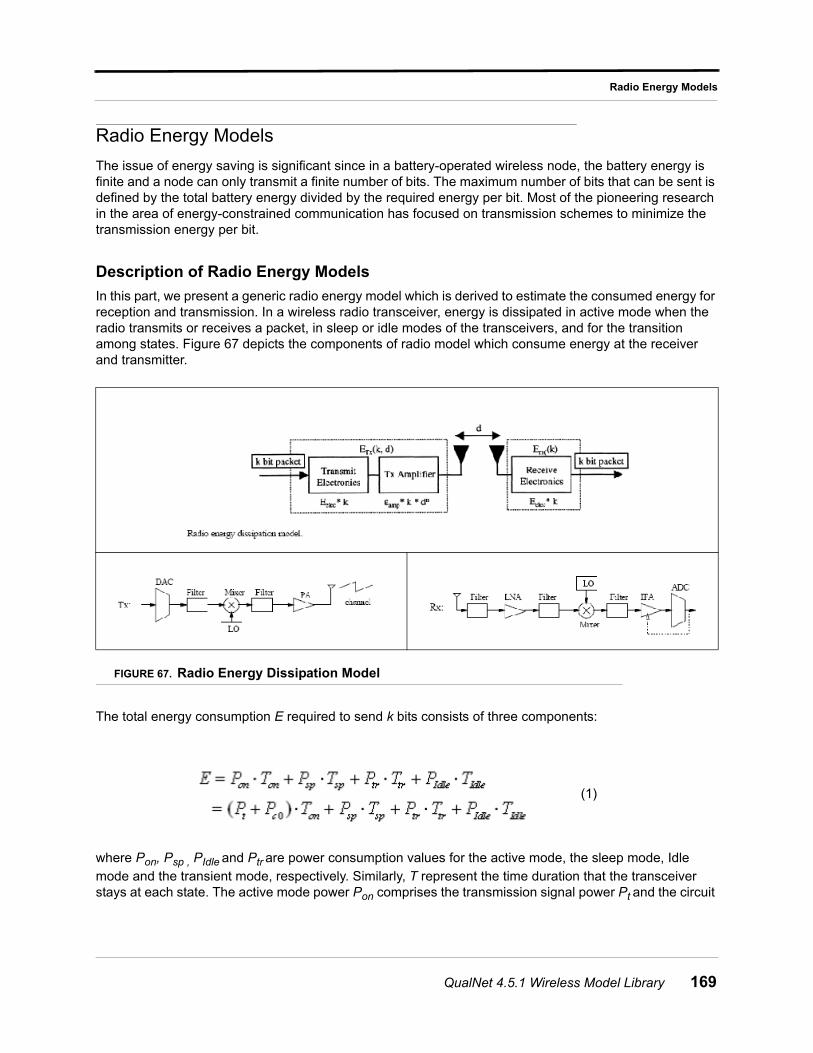
Radio Energy Models
Radio Energy Models
The issue of energy saving is significant since in a battery-operated wireless node, the battery energy is finite and a node can only transmit a finite number of bits. The maximum number of bits that can be sent is defined by the total battery energy divided by the required energy per bit. Most of the pioneering research in the area of energy-constrained communication has focused on transmission schemes to minimize the transmission energy per bit.
Description of Radio Energy Models
In this part, we present a generic radio energy model which is derived to estimate the consumed energy for reception and transmission. In a wireless radio transceiver, energy is dissipated in active mode when the radio transmits or receives a packet, in sleep or idle modes of the transceivers, and for the transition among states. Figure 67 depicts the components of radio model which consume energy at the receiver and transmitter.
FIGURE 67. Radio Energy Dissipation Model
The total energy consumption E required to send k bits consists of three components:
where Pon, Psp , PIdle and Ptr are power consumption values for the active mode, the sleep mode, Idle mode and the transient mode, respectively. Similarly, T represent the time duration that the transceiver stays at each state. The active mode power Pon comprises the transmission signal power Pt and the circuit
(1)
QualNet 4.5.1 Wireless Model Library 169
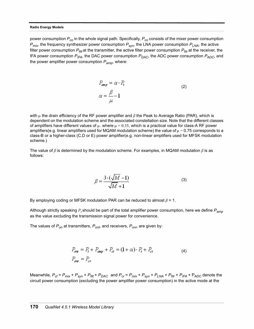
Radio Energy Models
power consumption Pco in the whole signal path. Specifically, Pco consists of the mixer power consumption Pmix, the frequency synthesizer power consumption Psyn, the LNA power consumption PLNA, the active filter power consumption Pfilt at the transmitter, the active filter power consumption Pfilr at the receiver, the IFA power consumption PIFA, the DAC power consumption PDAC, the ADC power consumption PADC, and the power amplifier power consumption Pamp, where:
with the drain efficiency of the RF power amplifier and β the Peak to Average Ratio (PAR), which is dependent on the modulation scheme and the associated constellation size. Note that the different classes of amplifiers have different values of . where = 0.35, which is a practical value for class-A RF power amplifiers(e.g. linear amplifiers used for MQAM modulation scheme) the value of = 0.75 corresponds to a class-B or a higher-class (C,D or E) power amplifier(e.g. non-linear amplifiers used for MFSK modulation scheme.)
The value of β is determined by the modulation scheme. For examples, in MQAM modulation β is as follows:
By employing coding or MFSK modulation PAR can be reduced to almost β = 1.
Although strictly speaking Pt should be part of the total amplifier power consumption, here we define Pamp as the value excluding the transmission signal power for convenience.
The values of Pon at transmitters, Pont, and receivers, Ponr, are given by:
Meanwhile, Pct = Pmix + Psyn + Pfilt + PDAC and Pcr = Pmix + Psyn + PLNA + Pfilr + PIFA + PADC denote the circuit power consumption (excluding the power amplifier power consumption) in the active mode at the
(2)
(3)
(4)
170 QualNet 4.5.1 Wireless Model Library
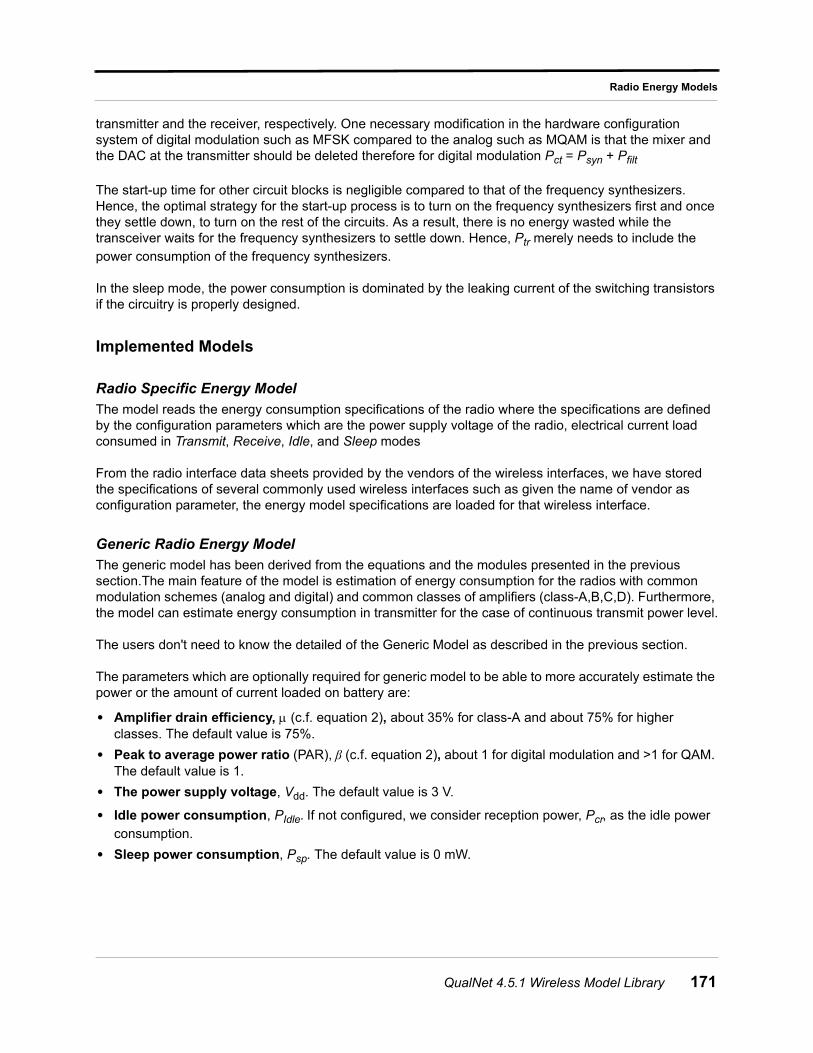
Radio Energy Models
transmitter and the receiver, respectively. One necessary modification in the hardware configuration system of digital modulation such as MFSK compared to the analog such as MQAM is that the mixer and the DAC at the transmitter should be deleted therefore for digital modulation Pct = Psyn + Pfilt
The start-up time for other circuit blocks is negligible compared to that of the frequency synthesizers. Hence, the optimal strategy for the start-up process is to turn on the frequency synthesizers first and once they settle down, to turn on the rest of the circuits. As a result, there is no energy wasted while the transceiver waits for the frequency synthesizers to settle down. Hence, Ptr merely needs to include the power consumption of the frequency synthesizers.
In the sleep mode, the power consumption is dominated by the leaking current of the switching transistors if the circuitry is properly designed.
Implemented Models
Radio Specific Energy Model
The model reads the energy consumption specifications of the radio where the specifications are defined by the configuration parameters which are the power supply voltage of the radio, electrical current load consumed in Transmit, Receive, Idle, and Sleep modes
From the radio interface data sheets provided by the vendors of the wireless interfaces, we have stored the specifications of several commonly used wireless interfaces such as given the name of vendor as configuration parameter, the energy model specifications are loaded for that wireless interface.
Generic Radio Energy Model
The generic model has been derived from the equations and the modules presented in the previous section.The main feature of the model is estimation of energy consumption for the radios with common modulation schemes (analog and digital) and common classes of amplifiers (class-A,B,C,D). Furthermore, the model can estimate energy consumption in transmitter for the case of continuous transmit power level.
The users don't need to know the detailed of the Generic Model as described in the previous section.
The parameters which are optionally required for generic model to be able to more accurately estimate the power or the amount of current loaded on battery are:
• Amplifier drain efficiency, (c.f. equation 2), about 35% for class-A and about 75% for higher classes. The default value is 75%.
• Peak to average power ratio (PAR), β (c.f. equation 2), about 1 for digital modulation and >1 for QAM. The default value is 1.
• The power supply voltage, Vdd. The default value is 3 V.
• Idle power consumption, PIdle. If not configured, we consider reception power, Pcr, as the idle power consumption.
• Sleep power consumption, Psp. The default value is 0 mW.
QualNet 4.5.1 Wireless Model Library 171
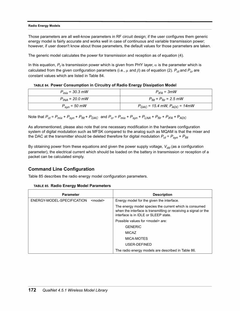
Radio Energy Models
Those parameters are all well-know parameters in RF circuit design; if the user configures them generic energy model is fairly accurate and works well in case of continuous and variable transmission power; however, if user doesn't know about those parameters, the default values for those parameters are taken.
The generic model calculates the power for transmission and reception as of equation (4).
In this equation, Pt is transmission power which is given from PHY layer, is the parameter which is calculated from the given configuration parameters (i.e., and β) as of equation (2). Pct and Pcr are constant values which are listed in Table 84.
Note that Pct = Pmix + Psyn + Pfilt + PDAC and Pcr = Pmix + Psyn + PLNA + Pfilr + PIFA + PADC
As aforementioned, please also note that one necessary modification in the hardware configuration system of digital modulation such as MFSK compared to the analog such as MQAM is that the mixer and the DAC at the transmitter should be deleted therefore for digital modulation Pct = Psyn + Pfilt
By obtaining power from these equations and given the power supply voltage, Vdd (as a configuration parameter), the electrical current which should be loaded on the battery in transmission or reception of a packet can be calculated simply.
Command Line Configuration
Table 85 describes the radio energy model configuration parameters.
TABLE 84. Power Consumption in Circuitry of Radio Energy Dissipation Model
Pmix = 30.3 mW PIFA = 3mW
PINA = 20.0 mW Pfilt = Pfilr = 2.5 mW
Psyn = 50 mW PDAC = 15.4 mW, PADC = 14mW
TABLE 85. Radio Energy Model Parameters
Parameter Description
ENERGY-MODEL-SPECIFICATION <model> Energy model for the given the interface.
The energy model species the current which is consumed when the interface is transmitting or receiving a signal or the interface is in IDLE or SLEEP state.
Possible values for <model> are:
GENERIC
MICAZ
MICA-MOTES
USER-DEFINED
The radio energy models are described in Table 86.
172 QualNet 4.5.1 Wireless Model Library
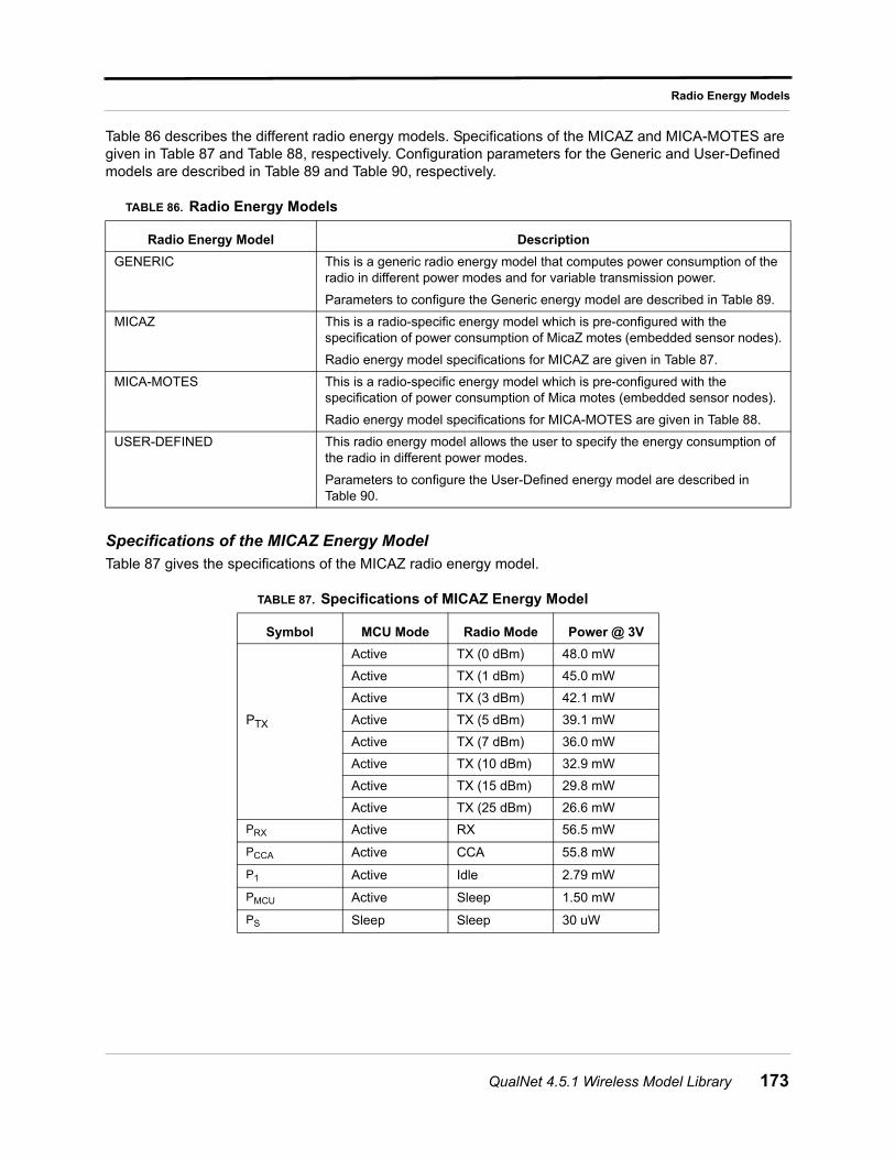
Radio Energy Models
Table 86 describes the different radio energy models. Specifications of the MICAZ and MICA-MOTES are given in Table 87 and Table 88, respectively. Configuration parameters for the Generic and User-Defined models are described in Table 89 and Table 90, respectively.
Specifications of the MICAZ Energy Model
Table 87 gives the specifications of the MICAZ radio energy model.
TABLE 86. Radio Energy Models
Radio Energy Model Description
GENERIC This is a generic radio energy model that computes power consumption of the radio in different power modes and for variable transmission power.
Parameters to configure the Generic energy model are described in Table 89.
MICAZ This is a radio-specific energy model which is pre-configured with the specification of power consumption of MicaZ motes (embedded sensor nodes).
Radio energy model specifications for MICAZ are given in Table 87.
MICA-MOTES This is a radio-specific energy model which is pre-configured with the specification of power consumption of Mica motes (embedded sensor nodes).
Radio energy model specifications for MICA-MOTES are given in Table 88.
USER-DEFINED This radio energy model allows the user to specify the energy consumption of the radio in different power modes.
Parameters to configure the User-Defined energy model are described in Table 90.
TABLE 87. Specifications of MICAZ Energy Model
Symbol MCU Mode Radio Mode Power @ 3V
PTX
Active TX (0 dBm) 48.0 mW
Active TX (1 dBm) 45.0 mW
Active TX (3 dBm) 42.1 mW
Active TX (5 dBm) 39.1 mW
Active TX (7 dBm) 36.0 mW
Active TX (10 dBm) 32.9 mW
Active TX (15 dBm) 29.8 mW
Active TX (25 dBm) 26.6 mW
PRX Active RX 56.5 mW
PCCA Active CCA 55.8 mW
P1 Active Idle 2.79 mW
PMCU Active Sleep 1.50 mW
PS Sleep Sleep 30 uW
QualNet 4.5.1 Wireless Model Library 173
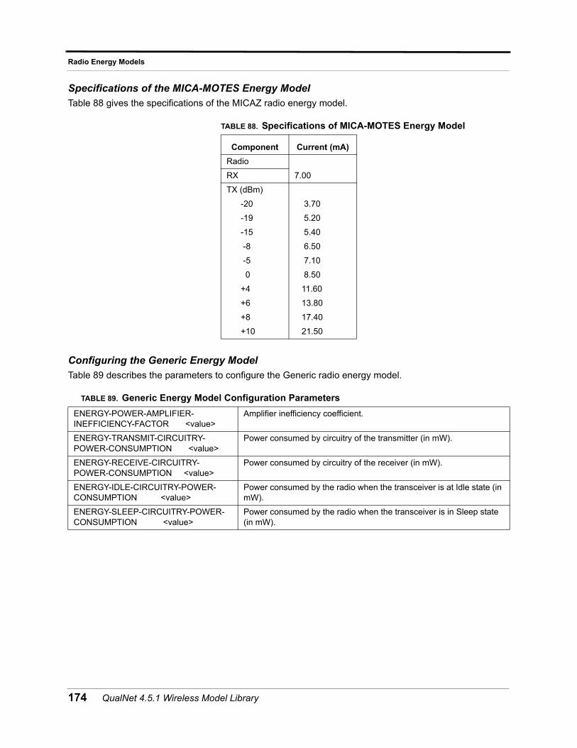
Radio Energy Models
Specifications of the MICA-MOTES Energy Model
Table 88 gives the specifications of the MICAZ radio energy model.
Configuring the Generic Energy Model
Table 89 describes the parameters to configure the Generic radio energy model.
TABLE 88. Specifications of MICA-MOTES Energy Model
Component Current (mA)
Radio
7.00RX
TX (dBm)
-20
-19
-15
-8
-5
0
+4
+6
+8
+10
3.70
5.20
5.40
6.50
7.10
8.50
11.60
13.80
17.40
21.50
TABLE 89. Generic Energy Model Configuration Parameters
ENERGY-POWER-AMPLIFIER-INEFFICIENCY-FACTOR <value>
Amplifier inefficiency coefficient.
ENERGY-TRANSMIT-CIRCUITRY-POWER-CONSUMPTION <value>
Power consumed by circuitry of the transmitter (in mW).
ENERGY-RECEIVE-CIRCUITRY-POWER-CONSUMPTION <value>
Power consumed by circuitry of the receiver (in mW).
ENERGY-IDLE-CIRCUITRY-POWER-CONSUMPTION <value>
Power consumed by the radio when the transceiver is at Idle state (in mW).
ENERGY-SLEEP-CIRCUITRY-POWER-CONSUMPTION <value>
Power consumed by the radio when the transceiver is in Sleep state (in mW).
174 QualNet 4.5.1 Wireless Model Library
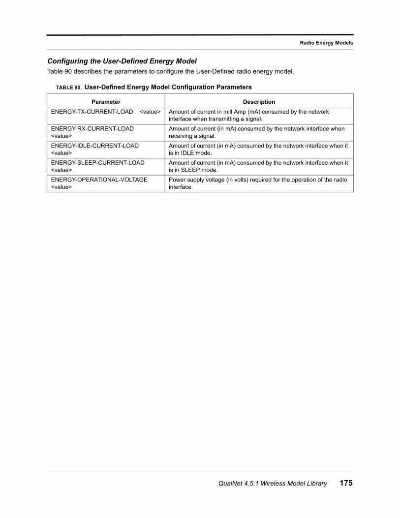
Radio Energy Models
Configuring the User-Defined Energy Model
Table 90 describes the parameters to configure the User-Defined radio energy model.
TABLE 90. User-Defined Energy Model Configuration Parameters
Parameter Description
ENERGY-TX-CURRENT-LOAD <value> Amount of current in mill Amp (mA) consumed by the network interface when transmitting a signal.
ENERGY-RX-CURRENT-LOAD <value>
Amount of current (in mA) consumed by the network interface when receiving a signal.
ENERGY-IDLE-CURRENT-LOAD <value>
Amount of current (in mA) consumed by the network interface when it is in IDLE mode.
ENERGY-SLEEP-CURRENT-LOAD <value>
Amount of current (in mA) consumed by the network interface when it is in SLEEP mode.
ENERGY-OPERATIONAL-VOLTAGE <value>
Power supply voltage (in volts) required for the operation of the radio interface.
QualNet 4.5.1 Wireless Model Library 175
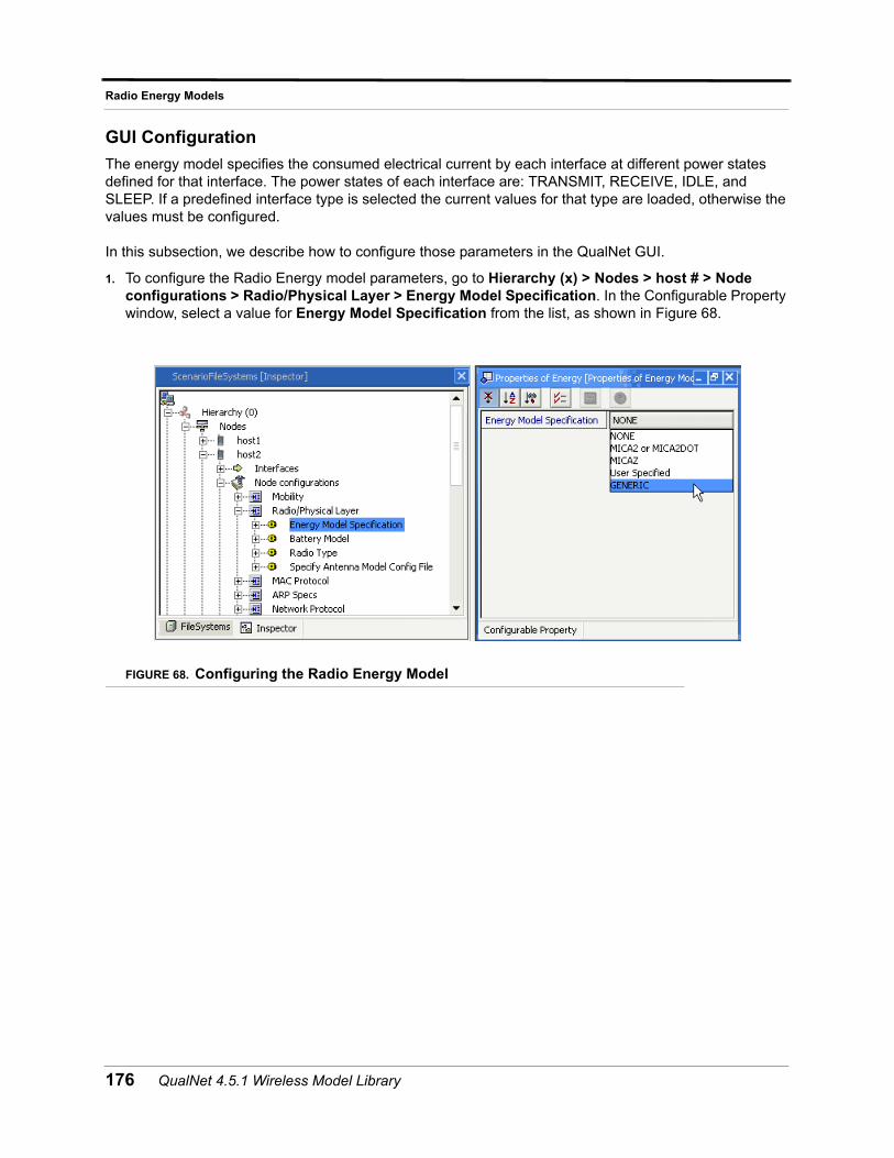
Radio Energy Models
GUI Configuration
The energy model specifies the consumed electrical current by each interface at different power states defined for that interface. The power states of each interface are: TRANSMIT, RECEIVE, IDLE, and SLEEP. If a predefined interface type is selected the current values for that type are loaded, otherwise the values must be configured.
In this subsection, we describe how to configure those parameters in the QualNet GUI.
1. To configure the Radio Energy model parameters, go to Hierarchy (x) > Nodes > host # > Node configurations > Radio/Physical Layer > Energy Model Specification. In the Configurable Property window, select a value for Energy Model Specification from the list, as shown in Figure 68.
FIGURE 68. Configuring the Radio Energy Model
176 QualNet 4.5.1 Wireless Model Library
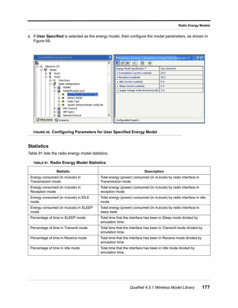
Radio Energy Models
2. If User Specified is selected as the energy model, then configure the model parameters, as shown in Figure 69.
FIGURE 69. Configuring Parameters for User Specified Energy Model
Statistics
Table 91 lists the radio energy model statistics.
TABLE 91. Radio Energy Model Statistics
Statistic Description
Energy consumed (in mJoule) in Transmission mode
Total energy (power) consumed (in mJoule) by radio interface in Transmission mode
Energy consumed (in mJoule) in Reception mode
Total energy (power) consumed (in mJoule) by radio interface in reception mode
Energy consumed (in mJoule) in IDLE mode
Total energy (power) consumed (in mJoule) by radio interface in idle mode
Energy consumed (in mJoule) in SLEEP mode
Total energy (power) consumed (in mJoule) by radio interface in sleep state
Percentage of time in SLEEP mode Total time that the interface has been in Sleep mode divided by simulation time.
Percentage of time in Transmit mode Total time that the interface has been in Transmit mode divided by simulation time.
Percentage of time in Receive mode Total time that the interface has been in Receive mode divided by simulation time.
Percentage of time in Idle mode Total time that the interface has been in Idle mode divided by simulation time.
QualNet 4.5.1 Wireless Model Library 177
Random Waypoint Mobility Model
Random Waypoint Mobility Model
Random Waypoint mobility selects random destinations and speeds for each node. After the nodes reach their selected destinations, they pause for a given amount of time, specified by MOBILITY-WP-PAUSE and then the process is repeated.
Command Line Configuration
To select Random Waypoint mobility as the mobility model, place the following entry in *.config:
MOBILITY RANDOM-WAYPOINT
Table 92 shows the Random Mobility parameters.
Statistics
There are no statistics collected for this model.
TABLE 92. Random Mobility Parameters
Parameter name Description
MOBILITY-WP-PAUSE <time> This parameter is used to specify the delay while the node is mobile.
This is a mandatory parameter
MOBILITY-WP-MIN-SPEED <speed> This parameter is used to specify minimum waypoint speed (in meters/sec).
This is a mandatory parameter
MOBILITY-WP-MAX-SPEED <speed> This parameter is used to specify maximum waypoint speed (in meters/sec).
This is a mandatory parameter.
MOBILITY-POSITION-GRANULARITY <granularity-value>
This parameter is used to specify mobility granularity for the device to move.
The default value is 1.0
MOBILITY-GROUND-NODE [YES | NO] If yes, nodes get their altitude from the terrain file, if one is specified.
The default value is YES
178 QualNet 4.5.1 Wireless Model Library
Rayleigh Fading Model
Rayleigh Fading Model
Rayleigh fading model is a statistical model to represent the fast variation of signal amplitude at the receiver. In wireless propagation, Rayleigh fading occurs when there is no line of sight between the transmitter and receiver. The fading speed is affected by how fast the receiver and/or transmitter, or the surrounding objects are moving.
QualNet’s Rayleigh fading model uses pre-computed time series data sequence with different sample intervals to represent the different fading speeds or coherence times of the propagation channel.
Command Line Configuration
To select this model, set the parameter PROPAGATION-FADING-MODEL in the configuration file as follows:
PROPAGATION-FADING-MODEL[<Index>] RAYLEIGH
where
<Index> : Index of channel to which this parameter declaration is applicable, enclosed in square brackets. This should be in the range 0 to n -1, where n is the number of channels.
The instance specification is optional. If an instance is not included, then the parameter declaration is applicable to all channels.
Table 93 lists the parameters for the Rayleigh fading model.
TABLE 93. Rayleigh Fading Model Parameters
Parameter Name Description
PROPAGATION-FADING-GAUSSIAN-COMPONENTS-FILE <filename>
Specifies the name of the file that stores the series of Gaussian components.
The format of this file is described below.
This is a mandatory parameter.
PROPAGATION-FADING-MAX-VELOCITY <velocity>
Specifies the maximum velocity (in meters/sec) of the nodes or the surrounding objects in a scenario. In general, the fading speed increases with the motion speed.
This is a mandatory parameter.
QualNet 4.5.1 Wireless Model Library 179

Rayleigh Fading Model
Format of the Gaussian Components File
The first three lines of the Gaussian components file specify the sampling rate, base Doppler frequency, and the number of Gaussian components. The first three lines are:
SAMPLING-RATE <sampling rate> BASE-DOPPLER-FREQUENCY <base Doppler frequency> NUMBER-OF-GAUSSIAN-COMPONENTS <number of Gaussian components>
where
<sampling rate> : Sampling rate, in Hz.
<base doppler frequency> : Base Doppler frequency, in HZ.
<number of Gaussian components> : Number of Gaussian components in the file.
These lines are followed by <number of Gaussian components> lines, in the following format:
<Gaussian component 1> <Gaussian component 2>
where:
<Gaussian component 1>: First Gaussian component.
<Gaussian component 2>: Second Gaussian component.
A default Gaussian compounds file, default.fading, can be found in QUALNET_HOME/scenarios/default. A segment of this file is shown below.
SAMPLING-RATE 1000BASE-DOPPLER-FREQUENCY 30.0NUMBER-OF-GAUSSIAN-COMPONENTS 16384
-5.6482112e-001 -1.2675110e+000-5.7047958e-001 -1.0847877e+000-5.6146223e-001 -8.8065119e-001-5.4280320e-001 -6.6004259e-001-5.1605105e-001 -4.2597880e-001-4.7640535e-001 -1.8909923e-001...
Statistics
There are no statistics collected for this model.
180 QualNet 4.5.1 Wireless Model Library
Ricean Fading Model
Ricean Fading Model
Ricean fading model is a statistical model to represent the fast variation of signal amplitude at the receiver. In wireless propagation, Ricean fading occurs when there is line of sight between the transmitter and receiver, and the line of sight signal is the dominant signal seen at the receiver.
QualNet’s Ricean fading model uses pre-computed time series data sequence with different sample intervals to represent the different fading speeds or coherence times of the propagation channel.
Command Line Configuration
To select this model, set the parameter PROPAGATION-FADING-MODEL in the configuration file as follows:
PROPAGATION-FADING-MODEL[<Index>] RICEAN
where
<Index> : Index of channel to which this parameter declaration is applicable, enclosed in square brackets. This should be in the range 0 to n -1, where n is the number of channels.
The instance specification is optional. If an instance is not included, then the parameter declaration is applicable to all channels.
Table 94 lists the parameters for the Racing fading model.
TABLE 94. Ricean Fading Model Parameters
Parameter Name Description
PROPAGATION-FADING-GAUSSIAN-COMPONENTS-FILE <filename>
Specifies the name of the file that stores the series of Gaussian components.
The format of this file is described below.
This is a mandatory parameter.
PROPAGATION-FADING-MAX-VELOCITY <velocity>
Specifies the maximum velocity (in meters/sec) of the nodes or the surrounding objects in the scenario.
In general, the fading speed increases with the motion speed.
This is a mandatory parameter.
PROPAGATION-RICEAN-K-FACTOR <value> Specifies the Ricean K factor (linear value).
The K factor specifies the ratio of the signal power of the dominant component to the scattered power.
This is a mandatory parameter.
QualNet 4.5.1 Wireless Model Library 181
Ricean Fading Model
Format of the Gaussian Components File
The first three lines of the Gaussian components file specify the sampling rate, base Doppler frequency, and the number of Gaussian components. The first three lines are:
SAMPLING-RATE <sampling rate> BASE-DOPPLER-FREQUENCY <base Doppler frequency> NUMBER-OF-GAUSSIAN-COMPONENTS <number of Gaussian components>
where
<sampling rate> : Sampling rate, in Hz.
<base doppler frequency> : Base Doppler frequency, in HZ.
<number of Gaussian components> : Number of Gaussian components in the file.
These lines are followed by <number of Gaussian components> lines, in the following format:
<Gaussian component 1> <Gaussian component 2>
where:
<Gaussian component 1>: First Gaussian component.
<Gaussian component 2>: Second Gaussian component.
A default Gaussian compounds file, default.fading, can be found in QUALNET_HOME/scenarios/default. A segment of this file is shown below.
SAMPLING-RATE 1000BASE-DOPPLER-FREQUENCY 30.0NUMBER-OF-GAUSSIAN-COMPONENTS 16384
-5.6482112e-001 -1.2675110e+000-5.7047958e-001 -1.0847877e+000-5.6146223e-001 -8.8065119e-001-5.4280320e-001 -6.6004259e-001-5.1605105e-001 -4.2597880e-001-4.7640535e-001 -1.8909923e-001...
Statistics
There are no statistics collected for this model.
182 QualNet 4.5.1 Wireless Model Library
SNR-based Reception Model
SNR-based Reception Model
The Signal-to-Noise Ratio (SNR)-based model uses a user-specified threshold to evaluate reception quality. If the Signal to Interference plus Noise Ratio (SINR) value of the received signal is larger than this threshold, the packet is successfully received; otherwise, the packet is treated as corrupted.
Command Line Configuration
To select this model, set the parameter PHY-RX-MODEL in the configuration file as follows:
[<Qualifier>] PHY-RX-MODEL SNR-BASED
where
<Qualifier> : Node identifier(s) or address(es) of the subnet(s) or interface(s) to which this parameter declaration is applicable, enclosed in square brackets. If a qualifier is not included, the parameter declaration is applicable to the entire scenario (to all nodes, subnets, and interfaces), subject to rules of precedence.
Table 95 lists the parameters for the SNR-based reception model.
Statistics
There are no statistics collected for this model.
TABLE 95. SNR-based Reception Model Parameters
Parameter Name Description
PHY-RX-SNR-THRESHOLD <value> Specifies the threshold value (in dB) for likely error-free reception.
QualNet 4.5.1 Wireless Model Library 183
Source Tree Adaptive Routing (STAR) Protocol
Source Tree Adaptive Routing (STAR) Protocol
STAR is a partial link state, table driven protocol, in which the routers exchange only the changes in their own shortest path trees with their neighbors. STAR operates in either the Least Overhead Routing Approach (LORA), or Optimum Routing Approach (ORA) modes. In LORA mode, STAR attempts to provide viable, if not necessarily optimal (according to performance, delay metrics) paths to each destination, while in ORA mode, STAR attempts to provide optimal paths based on the chosen metric.
Command Line Configuration
To select STAR as the routing protocol, place the following entry in the scenario configuration (.config) file:
ROUTING-PROTOCOL STAR
STAR configuration parameters are described in Table 96.
GUI Configuration
To configure STAR in the QualNet GUI, complete the following steps:
1. Go to ConfigSettings > Network Protocols > Routing Protocol > Routing Policy.
2. In the Configurable Property window, set Routing Policy to Dynamic.
3. Go to ConfigSettings > Network Protocol > Routing Protocol > Routing Policy > Routing Protocol for IPv4.
4. In the Configurable Property window, set Routing Protocol for IPv4 to STAR and set the STAR parameters.
Statistics
Table 97 lists the statistics collected by the STAR model.
TABLE 96. STAR Parameters
Parameter Description
STAR-ROUTING-MODE <value> Specifies a choice between the routing modes.
The possible values are ORA or LORA.
This is a mandatory parameter.
NEIGHBOR-PROTOCOL-SEND-FREQUENCY <time>
Specifies the rate at which the neighbor protocol broadcasts hello packets to all neighbors.
This is a mandatory parameter.
NEIGHBOR-PROTOCOL-ENTRY-TTL <time>
Species how long the entries for neighbors remain valid after hearing a hello message.
This is a mandatory parameter.
184 QualNet 4.5.1 Wireless Model Library
Source Tree Adaptive Routing (STAR) Protocol
TABLE 97. STAR Statistics
Statistic Description
Update Packets Sent Total number of update packets sent by the node
Update Packets Received Total number of update packets received by the node
Link State Updates Sent Total number of link state updates sent by the node
Link State Updates Received Total number of link state updates received by the node
QualNet 4.5.1 Wireless Model Library 185
Steerable Antenna Model
Steerable Antenna Model
The steerable antenna is a special type of patterned antennae. A patterned antenna has different gains in different directions. The values of the gain in different directions follow a gain pattern. The steerable antenna can rotate the antenna and uses the direction that yields the maximum antenna gain.
Command Line Configuration
To select the steerable antenna model, set the parameter ANTENNA-MODEL in the configuration file as follows:
[<Qualifier>] ANTENNA-MODEL STEERABLE
where
<Qualifier> : Node identifier(s) or address(es) of the subnet(s) or interface(s) to which this parameter declaration is applicable, enclosed in square brackets. If a qualifier is not included, the parameter declaration is applicable to the entire scenario (to all nodes, subnets, and interfaces), subject to rules of precedence.
The parameters for the steerable antenna model are described in Table 98.
Format of Azimuth and Elevation Pattern Files
Both the azimuth and elevation pattern files have the same format.
The first line of the file specifies the number of patterns contained in the file and has the following format:
NUMBER-OF-RADIATION-PATTERNS <num-patterns>
where
<num-patterns> : Number of patterns in the file.
TABLE 98. Steerable Antenna Model Parameters
Parameter Name Description
ANTENNA-AZIMUTH-PATTERN-FILE <filename> Specifies the name of the antenna azimuth pattern fie.
The azimuth pattern file specifies the antenna gain at different azimuths.
The format of the file is described below.
This is a mandatory parameter.
ANTENNA-ELEVATION-PATTERN-FILE <filename>
Specifies the name of the antenna elevation pattern fie.
The elevation pattern file specifies the antenna gain at different elevations. This file is used only for three-dimensional antenna patterns.
The number of patterns in the antenna elevation pattern file should be the same as the number of patterns in the antenna azimuth pattern file.
The format of the file is described below.
This is a mandatory parameter.
186 QualNet 4.5.1 Wireless Model Library
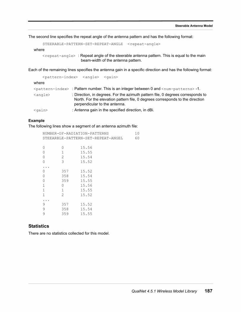
Steerable Antenna Model
The second line specifies the repeat angle of the antenna pattern and has the following format:
STEERABLE-PATTERN-SET-REPEAT-ANGLE <repeat-angle>
where
<repeat-angle> : Repeat angle of the steerable antenna pattern. This is equal to the main beam-width of the antenna pattern.
Each of the remaining lines specifies the antenna gain in a specific direction and has the following format:
<pattern-index> <angle> <gain>
where
<pattern-index> : Pattern number. This is an integer between 0 and <num-patterns> -1.
<angle> : Direction, in degrees. For the azimuth pattern file, 0 degrees corresponds to North. For the elevation pattern file, 0 degrees corresponds to the direction perpendicular to the antenna.
<gain> : Antenna gain in the specified direction, in dBi.
Example
The following lines show a segment of an antenna azimuth file:
NUMBER-OF-RADIATION-PATTERNS 10STEEARBLE-PATTERN-SET-REPEAT-ANGEL 60
0 0 15.560 1 15.550 2 15.540 3 15.52...0 357 15.520 358 15.540 359 15.551 0 15.561 1 15.551 2 15.52...9 357 15.529 358 15.549 359 15.55
Statistics
There are no statistics collected for this model.
QualNet 4.5.1 Wireless Model Library 187
Switched-beam Antenna Model
Switched-beam Antenna Model
The switched-beam antenna is a special type of patterned antennae. A patterned antenna has different gains in different directions. The values of the gain in different directions follow a gain pattern. A switched beam antenna can utilize multiple antenna patterns.
Command Line Configuration
To select the switched-beam antenna model, set the parameter ANTENNA-MODEL in the configuration file as follows:
[<Qualifier>] ANTENNA-MODEL SWITCHED-BEAM
where
<Qualifier> : Node identifier(s) or address(es) of the subnet(s) or interface(s) to which this parameter declaration is applicable, enclosed in square brackets. If a qualifier is not included, the parameter declaration is applicable to the entire scenario (to all nodes, subnets, and interfaces), subject to rules of precedence.
The parameters for the switched-beam antenna model are described in Table 99.
Format of Azimuth and Elevation Pattern Files
Both the azimuth and elevation pattern files have the same format.
The first line of the file specifies the number of patterns contained in the file and has the following format:
NUMBER-OF-RADIATION-PATTERNS <num-patterns>
where
<num-patterns> : Number of patterns in the file.
TABLE 99. Switched-beam Antenna Model Parameters
Parameter Name Description
ANTENNA-AZIMUTH-PATTERN-FILE <filename> Specifies the name of the antenna azimuth pattern fie.
The azimuth pattern file specifies the antenna gain at different azimuths.
The format of the file is described below.
This is a mandatory parameter.
ANTENNA-ELEVATION-PATTERN-FILE <filename>
Specifies the name of the antenna elevation pattern fie.
The elevation pattern file specifies the antenna gain at different elevations. This file is used only for three-dimensional antenna patterns.
The number of patterns in the antenna elevation pattern file should be the same as the number of patterns in the antenna azimuth pattern file.
The format of the file is described below.
This is a mandatory parameter.
188 QualNet 4.5.1 Wireless Model Library
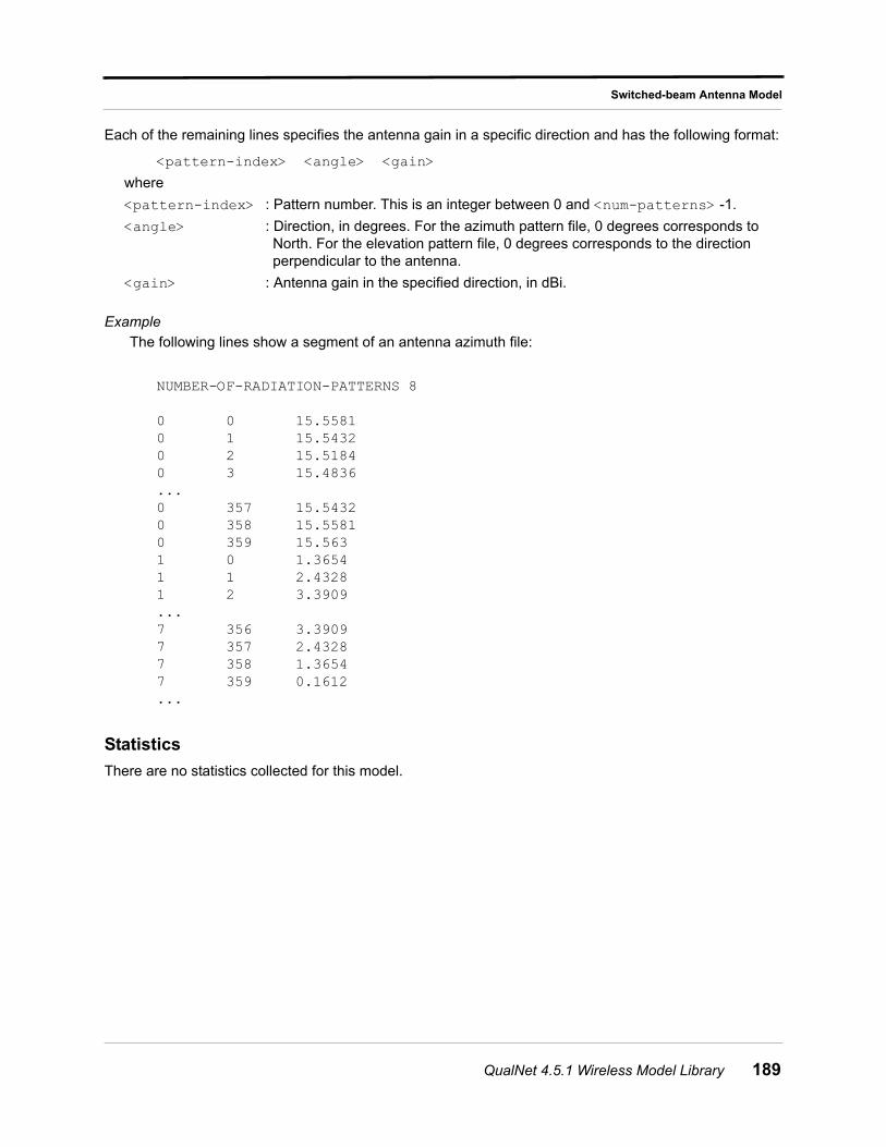
Switched-beam Antenna Model
Each of the remaining lines specifies the antenna gain in a specific direction and has the following format:
<pattern-index> <angle> <gain>
where
<pattern-index> : Pattern number. This is an integer between 0 and <num-patterns> -1.
<angle> : Direction, in degrees. For the azimuth pattern file, 0 degrees corresponds to North. For the elevation pattern file, 0 degrees corresponds to the direction perpendicular to the antenna.
<gain> : Antenna gain in the specified direction, in dBi.
Example
The following lines show a segment of an antenna azimuth file:
NUMBER-OF-RADIATION-PATTERNS 8
0 0 15.55810 1 15.54320 2 15.51840 3 15.4836...0 357 15.54320 358 15.55810 359 15.5631 0 1.36541 1 2.43281 2 3.3909...7 356 3.39097 357 2.43287 358 1.36547 359 0.1612...
Statistics
There are no statistics collected for this model.
QualNet 4.5.1 Wireless Model Library 189
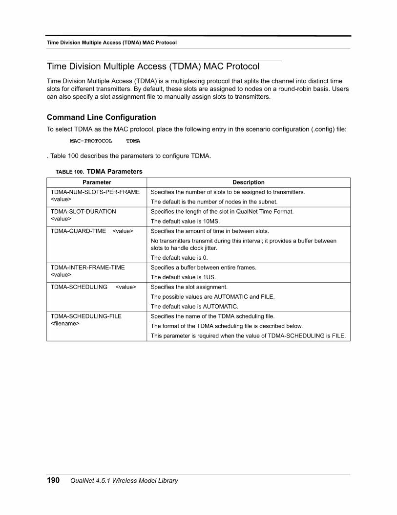
Time Division Multiple Access (TDMA) MAC Protocol
Time Division Multiple Access (TDMA) MAC Protocol
Time Division Multiple Access (TDMA) is a multiplexing protocol that splits the channel into distinct time slots for different transmitters. By default, these slots are assigned to nodes on a round-robin basis. Users can also specify a slot assignment file to manually assign slots to transmitters.
Command Line Configuration
To select TDMA as the MAC protocol, place the following entry in the scenario configuration (.config) file:
MAC-PROTOCOL TDMA
. Table 100 describes the parameters to configure TDMA.
TABLE 100. TDMA Parameters
Parameter Description
TDMA-NUM-SLOTS-PER-FRAME <value>
Specifies the number of slots to be assigned to transmitters.
The default is the number of nodes in the subnet.
TDMA-SLOT-DURATION <value>
Specifies the length of the slot in QualNet Time Format.
The default value is 10MS.
TDMA-GUARD-TIME <value> Specifies the amount of time in between slots.
No transmitters transmit during this interval; it provides a buffer between slots to handle clock jitter.
The default value is 0.
TDMA-INTER-FRAME-TIME <value>
Specifies a buffer between entire frames.
The default value is 1US.
TDMA-SCHEDULING <value> Specifies the slot assignment.
The possible values are AUTOMATIC and FILE.
The default value is AUTOMATIC.
TDMA-SCHEDULING-FILE <filename>
Specifies the name of the TDMA scheduling file.
The format of the TDMA scheduling file is described below.
This parameter is required when the value of TDMA-SCHEDULING is FILE.
190 QualNet 4.5.1 Wireless Model Library
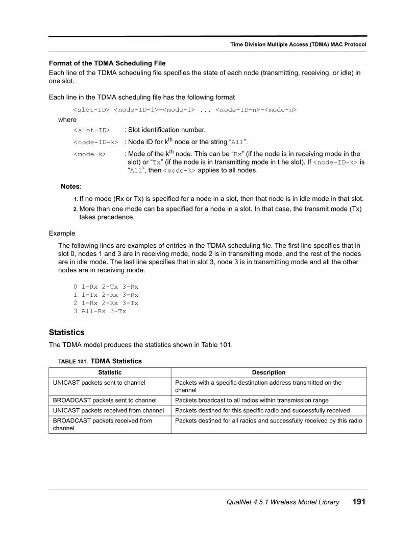
Time Division Multiple Access (TDMA) MAC Protocol
Format of the TDMA Scheduling File
Each line of the TDMA scheduling file specifies the state of each node (transmitting, receiving, or idle) in one slot.
Each line in the TDMA scheduling file has the following format
<slot-ID> <node-ID-1>-<mode-1> ... <node-ID-n>-<mode-n>
where
<slot-ID> : Slot identification number.
<node-ID-k> : Node ID for kth node or the string “All”.
<mode-k> : Mode of the kth node. This can be “Rx” (if the node is in receiving mode in the slot) or “Tx” (if the node is in transmitting mode in t he slot). If <node-ID-k> is “All”, then <mode-k> applies to all nodes.
Notes:
1. If no mode (Rx or Tx) is specified for a node in a slot, then that node is in idle mode in that slot.
2. More than one mode can be specified for a node in a slot. In that case, the transmit mode (Tx) takes precedence.
Example
The following lines are examples of entries in the TDMA scheduling file. The first line specifies that in slot 0, nodes 1 and 3 are in receiving mode, node 2 is in transmitting mode, and the rest of the nodes are in idle mode. The last line specifies that in slot 3, node 3 is in transmitting mode and all the other nodes are in receiving mode.
0 1-Rx 2-Tx 3-Rx1 1-Tx 2-Rx 3-Rx2 1-Rx 2-Rx 3-Tx3 All-Rx 3-Tx
Statistics
The TDMA model produces the statistics shown in Table 101.
TABLE 101. TDMA Statistics
Statistic Description
UNICAST packets sent to channel Packets with a specific destination address transmitted on the channel
BROADCAST packets sent to channel Packets broadcast to all radios within transmission range
UNICAST packets received from channel Packets destined for this specific radio and successfully received
BROADCAST packets received from channel
Packets destined for all radios and successfully received by this radio
QualNet 4.5.1 Wireless Model Library 191
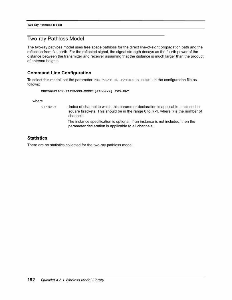
Two-ray Pathloss Model
Two-ray Pathloss Model
The two-ray pathloss model uses free space pathloss for the direct line-of-sight propagation path and the reflection from flat earth. For the reflected signal, the signal strength decays as the fourth power of the distance between the transmitter and receiver assuming that the distance is much larger than the product of antenna heights.
Command Line Configuration
To select this model, set the parameter PROPAGATION-PATHLOSS-MODEL in the configuration file as follows:
PROPAGATION-PATHLOSS-MODEL[<Index>] TWO-RAY
where
<Index> : Index of channel to which this parameter declaration is applicable, enclosed in square brackets. This should be in the range 0 to n -1, where n is the number of channels.
The instance specification is optional. If an instance is not included, then the parameter declaration is applicable to all channels.
Statistics
There are no statistics collected for the two-ray pathloss model.
192 QualNet 4.5.1 Wireless Model Library
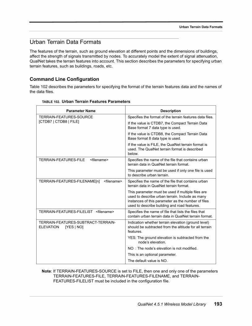
Urban Terrain Data Formats
Urban Terrain Data Formats
The features of the terrain, such as ground elevation at different points and the dimensions of buildings, affect the strength of signals transmitted by nodes. To accurately model the extent of signal attenuation, QualNet takes the terrain features into account. This section describes the parameters for specifying urban terrain features, such as buildings, roads, etc.
Command Line Configuration
Table 102 describes the parameters for specifying the format of the terrain features data and the names of the data files.
Note: If TERRAIN-FEATURES-SOURCE is set to FILE, then one and only one of the parameters TERRAIN-FEATURES-FILE, TERRAIN-FEATURES-FILENAME, and TERRAIN-FEATURES-FILELIST must be included in the configuration file.
TABLE 102. Urban Terrain Features Parameters
Parameter Name Description
TERRAIN-FEATURES-SOURCE [CTDB7 | CTDB8 | FILE]
Specifies the format of the terrain features data files.
If the value is CTDB7, the Compact Terrain Data Base format 7 data type is used.
If the value is CTDB8, the Compact Terrain Data Base format 8 data type is used.
If the value is FILE, the QualNet terrain format is used. The QualNet terrain format is described below.
TERRAIN-FEATURES-FILE <filename> Specifies the name of the file that contains urban terrain data in QualNet terrain format.
This parameter must be used if only one file is used to describe urban terrain.
TERRAIN-FEATURES-FILENAME[n] <filename> Specifies the name of the file that contains urban terrain data in QualNet terrain format.
This parameter must be used if multiple files are used to describe urban terrain. Include as many instances of this parameter as the number of files used to describe building and road features.
TERRAIN-FEATURES-FILELIST <filename> Specifies the name of file that lists the files that contain urban terrain data in QualNet terrain format.
TERRAIN-FEATURES-SUBTRACT-TERRAIN-ELEVATION [YES | NO]
Indication whether terrain elevation (ground level) should be subtracted from the altitude for all terrain features.
YES: The ground elevation is subtracted from the node’s elevation.
NO : The node’s elevation is not modified.
This is an optional parameter.
The default value is NO.
QualNet 4.5.1 Wireless Model Library 193
Urban Terrain Data Formats
QualNet Terrain Format
QualNet terrain format is a proprietary XML format provided by QualNet that allows users to define urban terrain features, such as buildings, roads, parks, and train stations. The format is described in Appendix A.
Urban terrain features data files in QualNet terrain format can be generated in the following ways:
• CTDB (format 7 and format 8) data can be converted into QualNet terrain format. To do this, set the parameter TERRAIN-FEATURES-SOURCE to CTDB7 (or CTDB8), specify the CTDB data parameters, and run the simulation. QualNet terrain format files representing the buildings and roads features are generated from CTDB database and used in the simulation. Once these files are generated, they can be reused in the simulation with the FILE option for the TERRAIN-FEATURES-SOURCE parameter.
• The Perl script “urban_grid.pl” can be used to generate files in QualNet terrain format for simple urban terrain descriptions. See Appendix A of QualNet 4.5 User’s Guide for details of this script.
• These files can be created manually by creating a new file or modifying an existing file.
194 QualNet 4.5.1 Wireless Model Library
Weather Pattern Model
Weather Pattern Model
You may specify weather patterns that move and affect propagation. Currently, the weather pattern model supports latitude/longitude coordinates. In addition to the parameters specified here, the most important parameter related to the weather implementation is the channel frequency. Higher frequency signals are more affected by the weather.
Command Line Configuration
Weather pattern configuration parameters are described in Table 103. These parameters must be specified int the scenario configuration (.config) file.
Format of the Weather Pattern Configuration File
The weather pattern configuration file specifies the shape and characteristics of one or more weather patterns as well as movement of the patterns.
The shape and characteristics are specified using the following format:
WEATHER-PATTERN[<id>] (<corner-1>;<corner-2>;<corner-3>;...) <altitude> <intensity> <polarization> <hierarchy ID>
where
<id> : Unique ID for the weather pattern. The ID for the first pattern is 0, and the others are numbered sequentially.
<corner-n> : Coordinates of the nth corner of the polygon that defines the weather pattern.
Each corner is specified in the following format:
<x>, <y>
where <x> is the X-coordinate and <y> is the Y-coordinate.
Note: Coordinates should be given in high precision, at least 10 significant digits
<altitude> : Altitude of the weather pattern, in meters.
<intensity> : Precipitation, in millimeters per hour.
<polarization> : Antenna type being modeled. Possible values are HORIZONTAL and VERTICAL.
<hierarchy ID> : Position of the weather pattern in QualNet GUI. A value of 0 indicates the outermost level.
TABLE 103. Weather Pattern Configuration Parameters
Parameter Description
WEATHER-CONFIG-FILE <weather file>
Specifies the name of the weather pattern configuration file.
The format of this file is described below. This file usually has the extension “.weather”.
WEATHER-MOBILITY-INTERVAL <interval>
Specifies the interval at which weather patterns move.
The default value of this parameter is 10S.
QualNet 4.5.1 Wireless Model Library 195
Weather Pattern Model
Example
The following is an example weather pattern consisting of a polygon of five points:
WEATHER-PATTERN[0] (22.318367,131.631;22.448,133.926;24.155,134.308;25.346,132.788;24.212,130.425)1000.0 10.0 HORIZONTAL 0
Weather movement is specified as a series of waypoints, which are interpreted as new positions for the first point of the weather pattern. The other points of the weather pattern are moved by the same delta.
The format of a waypoint is:
<id> <arrival time> (<x-ccordinate>,<y-coordinate>)
where
<id> : ID of the weather pattern.
<arrival time> : Arrival time of the weather pattern at this waypoint.
<x-coordinate> : New X-coordinate of the first corner of the weather pattern.
<y-coordinate> : New Y-coordinate of the first corner of the weather pattern.
Example
The following are examples of waypoints that specify future positions of weather pattern 0:
0 120S (21.820408163265718,132.61484467301395)0 240S (21.151020408163113,133.52699979150717)0 400S (20.80000000000036,135.02988393912017)0 800S (20.702040816326285,137.41017443880708)
196 QualNet 4.5.1 Wireless Model Library
Zone Routing Protocol (ZRP)
Zone Routing Protocol (ZRP)
Zone Routing Protocol (ZRP) is a hybrid protocol that divides the network into overlapping zones and runs independent protocols within and between the zones. For intrazone routing, ZRP uses IARP. For interzone routing, ZRP uses IERP. A third protocol, Bordercast Resolution Protocol (BRP), is used to optimize the routing process between perimeter nodes.
Command Line Configuration
To select ZRP as the routing protocol, place the following parameter in the *.config file:
ROUTING-PROTOCOL ZRP
ZRP configuration parameters are described in Table 104.
GUI Configuration
To configure ZRP in QualNet the GUI, complete the following steps:
1. Go to ConfigSettings > Network Protocols > Routing Protocol > Routing Policy.
2. In the Configurable Property window, set Routing Policy to Dynamic.
3. Go to ConfigSettings > Network Protocol > Routing Protocol > Routing Policy > Routing Protocol for IPv4.
4. In the Configurable Property window, set Routing Protocol for IPv4 to ZRP and set the ZRP parameters.
Statistics
See the BRP, IARP, and IERP sections of this model library for statistics collected by those models.
TABLE 104. ZRP Parameters
Parameter Description
ZONE-RADIUS <value> Specifies the zone radius.
The zone radius is an integer between 0 and INFINITY.
The default value is 2.
IERP-USE-BRP [YES | NO] Floods the query packets using bordercast.
The default value is NO.
QualNet 4.5.1 Wireless Model Library 197

Zone Routing Protocol (ZRP)
198 QualNet 4.5.1 Wireless Model Library
APPENDIX A QualNet Terrain Format
This appendix describes the XML format designed to represent terrain features in QualNet. The format is specified as an XML schema. This appendix describes this schema as well as additional conventions that are to be followed during the creation of XML files to describe terrain features.
Overall Description
Terrain Features
Terrain features are an important part of propagation modeling as well as mobility modeling. The XML format described in this appendix can be used as a QualNet standard format to specify terrain feature data relevant to network scenarios. Other terrain feature formats such as Geographic Information System (GIS) and Compact Terrain DataBase (CTDB) can be converted to the QualNet XML format using conversion addon modules available with QualNet.
Terrain features currently supported by the format include streets/street segments and intersections, buildings, open enclosures such as parks and stations, and railroads. Clouds, which are related to weather models, are also supported.
QualNet 4.5.1 Wireless Model Library 199
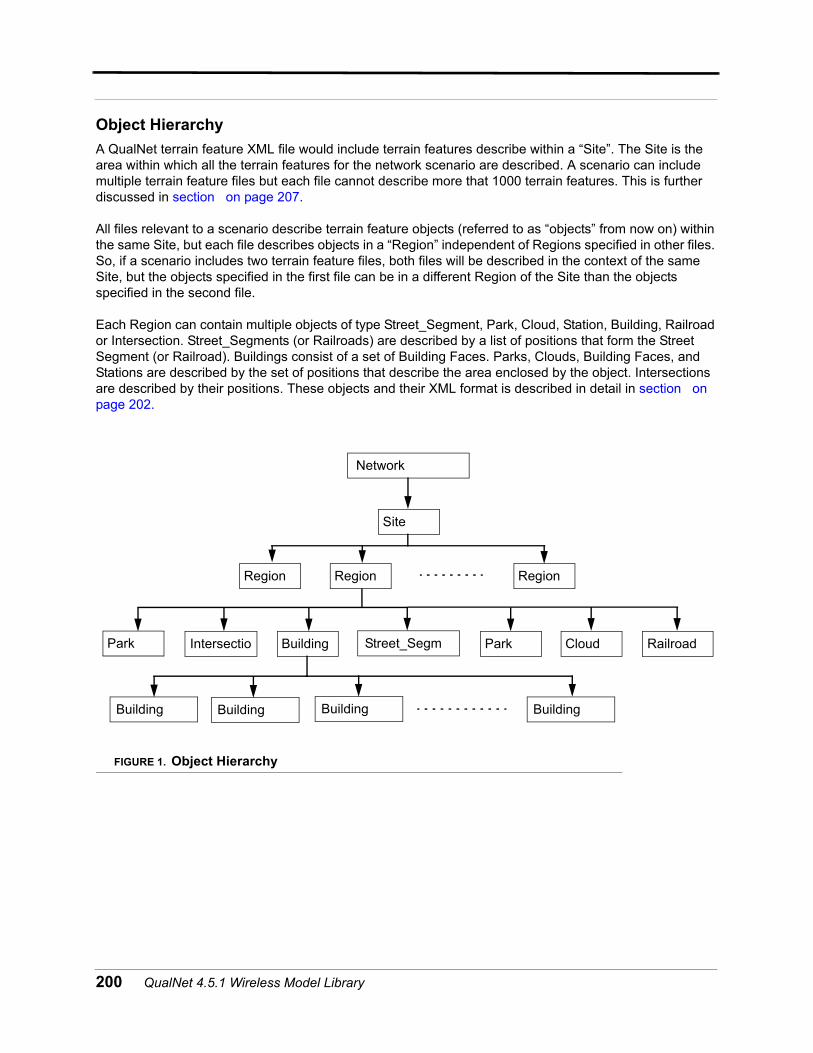
Object Hierarchy
A QualNet terrain feature XML file would include terrain features describe within a “Site”. The Site is the area within which all the terrain features for the network scenario are described. A scenario can include multiple terrain feature files but each file cannot describe more that 1000 terrain features. This is further discussed in section on page 207.
All files relevant to a scenario describe terrain feature objects (referred to as “objects” from now on) within the same Site, but each file describes objects in a “Region” independent of Regions specified in other files. So, if a scenario includes two terrain feature files, both files will be described in the context of the same Site, but the objects specified in the first file can be in a different Region of the Site than the objects specified in the second file.
Each Region can contain multiple objects of type Street_Segment, Park, Cloud, Station, Building, Railroad or Intersection. Street_Segments (or Railroads) are described by a list of positions that form the Street Segment (or Railroad). Buildings consist of a set of Building Faces. Parks, Clouds, Building Faces, and Stations are described by the set of positions that describe the area enclosed by the object. Intersections are described by their positions. These objects and their XML format is described in detail in section on page 202.
FIGURE 1. Object Hierarchy
Network
Region RegionRegion
Site
Street_Segm Park CloudBuildingIntersectio
Building Building
Park
Building
Railroad
Building
200 QualNet 4.5.1 Wireless Model Library
Coordinate Systems
Specifying Coordinate System Type
The Site object corresponding to each scenario must include the coordinate system type to be used in the file. The coordinate system type specified by the Site object is the global coordinate system type for all objects described in the scenario. This means that unless specified otherwise, all objects in the terrain feature files included in the scenario will describe position/location coordinates in this coordinate system.
Terrain feature objects and region objects can optionally specify a coordinate system type if required. Usually, this will be done if the coordinates of that object are to be described in a coordinate system different than that specified by the Site object.
Currently, the only supported coordinate systems are 3D Cartesian coordinates and WGS-84 geodetic coordinates. Cartesian coordinates are specified as “x-coordinate y-coordinate z-coordinate”. Geodetic coordinates are specified as “longitude latitude altitude”.
Specifying Reference Coordinates
The Site object corresponding to each scenario must include the reference coordinates to be used in the terrain feature files. The reference coordinates specified by the Site object are the global reference coordinates for all objects described in the scenario. This means that unless specified otherwise, all objects in the terrain feature files included in the scenario will describe position/location coordinates with reference to these reference coordinates.
Terrain feature objects and region objects can optionally specify reference coordinates if required. Usually, this will be done if the coordinates of that object are to be described with reference to a location different than the reference location specified by the Site object.
All reference coordinates can be specified in WGS-84 geodetic coordinates only.
Object Description
All objects covered in this section are described in terms of their attributes and the elements included in that object. The elements of an object must occur in the order in which they are described in this section.
Object IDs and References
The Site object, all region objects and all terrain feature objects are uniquely identified by character string IDs that are to be specified by the user. In addition, these objects can also have names. The ID of an object is used to maintain uniqueness of all objects.
Furthermore, it is also used by other objects as a reference. For example, intersections include references to all terrain feature objects that exist at the intersection. So, if three street segments meet at an intersection, the intersection will include the IDs of the three street segments as references to the street segment objects themselves. Since objects can be distributed across multiple files, objects in one file can
QualNet 4.5.1 Wireless Model Library 201
reference objects in another. But, the user must make sure that all objects referenced by an object must themselves be described in one of the files. No hanging references are allowed.
Site Object
Each terrain format file includes one Site object. The attributes of the Site object must be identical across all terrain format files that pertain to a scenario.
Site attributes
Site elements
Name: Name of the site (character string). This is an optional attribute.
id: Site ID (character string). This is a required attribute.
ReferencePoint: Global reference coordinates specified in geodetic coordinates. This is a required attribute.
CoordinateType: Global coordinate system type. The possible values are “cartesian” or “geodetic”. This is a required attribute.
totalParts: Number of files that the terrain features for this site are distributed over. This is a required attribute.
Part: File number corresponding to the file. This is a required attribute.
Region Object: Region specified by the file. This is a required attribute.
Sequence of terrain Feature Objects:
At most 1000 terrain feature objects (described in section 4.5). The different terrain feature objects can be listed in any order.
202 QualNet 4.5.1 Wireless Model Library
Base Object Types
All terrain feature objects are based on a set of base object types. Therefore, while the terrain feature objects can be changed by extension or inclusion of the base object types, the primary base objects will not change as they preserve the common elements between various terrain feature types.
refCollection type
This type is meant to hold a set of reference points such as the reference to street segments made by the intersection object.
refCollection type attributes
refCollection type elements
coordinate3D typeThis type is used to specify any position or location coordinates. It is a list of three numbers. The interpretation of these numbers is described in section 3.1.
linear typeThis type is used to describe any linear terrain features like street segments and railroads. The elements of this type must occur in the order specified below. Note that all linear objects must lie between two objects of the intersection type.
linear type attributes
Name: Name of the collection (character string). This is an optional attribute.
id: Object ID (character string). This is a required attribute.
reference sequence: Set of ID references each enclosed in “reference” tags.
Name: Name of the linear object (character string). This is an optional attribute.
id: Site ID (character string). This is a required attribute.
ReferencePoint: Global reference coordinates specified in geodetic coordinates. This is an optional attribute.
CoordinateType: Global coordinate system type. The possible values are “cartesian” or “geodetic”. This is a required attribute.
QualNet 4.5.1 Wireless Model Library 203
linear type elements
enclosure type
Enclosure type objects are relevant geographical areas in the scenario such as parks, stations. The region object is also an enclosure.
enclosure type attributes
enclosure type elements
firstNode: An object of type coordinate3D with a “objectRef” attribute. This element specifies the location of the first node of the linear object. The objectRef attribute is a reference to the intersection that the firstNode is part of.
node sequence: An optional sequence of objects of type coordinate3D, each with an optional “objectRef” attribute. A node element specifies the location of any intermediary nodes of the linear object. The optional objectRef attribute is a reference to the intersection that the node may be a part of.
lastNode: An object of type coordinate3D with a “objectRef” attribute. This element specifies the location of the last node of the linear object. The objectRef attribute is a reference to the intersection that the lastNode is part of.
Name: Name of the linear object (character string). This is an optional attribute.
id: Site ID (character string). This is a required attribute.
ReferencePoint: Global reference coordinates specified in geodetic coordinates. It is optional.
CoordinateType: Global coordinate system type. The possible values are “cartesian” or “geodetic”. This is a required attribute.
position sequence: A sequence of at least three objects of type coordinate3D, each with an optional exitIntersectionID attribute. A position object signifies the coordinates of a single vertex of the two dimensional structure. The sequence of positions make up the structure. The exitIntersectionID is a reference to the intersection the enclosure may be a part of.
representative sequence:
A sequence of objects of type coordinate3D. It indicates the position of a representative (such as station or park information booth) at the enclosure.
204 QualNet 4.5.1 Wireless Model Library
intersection type
This is the base object for street intersections.
intersection type attributes
intersection type elements
Name: Name of the linear object (character string). This is an optional attribute.
id: Site ID (character string). This is a required attribute.
ReferencePoint: Global reference coordinates specified in geodetic coordinates. This is an optional attribute.
CoordinateType: Global coordinate system type. The possible values are “cartesian” or “geodetic”. This is a required attribute.
location: An object type coordinate3D. It indicates the location of the intersection.
synchronized signals sequence:
A sequence of objects of type refCollection. Each synchronizedSignals object includes references to a subset of the IDs of street segments that meet at that intersection. The subset of street segments that are referenced by a synchronizedSignals object are the street segments for which the traffic signals are synchronized.
objects: An object of type refCollection. This is the list of ID references to all the objects that meet at the intersection.
QualNet 4.5.1 Wireless Model Library 205
structure2D type
This object type is used to describe two-dimensional structures. This includes building faces and clouds.
structure2D type attributes
structure2D type elements
structure3D type
This object type is used to describe three-dimensional structures. This includes buildings.
structure3D type attributes
Structure3D type elements
Name: Name of the structure2D object (character string). This is an optional attribute.
id: Site ID (character string). This is a required attribute.
ReferencePoint: Global reference coordinates specified in geodetic coordinates. This is an optional attribute.
CoordinateType: Global coordinate system type. The possible values are “cartesian” or “geodetic”. This is a required attribute.
position sequence: A sequence of at least three objects of type coordinate3D. A position object signifies the coordinates of a single vertex of the two dimensional structure. The sequence of positions makeup the structure.
thickness: A decimal value indicating the thickness of the structure.
Name: Name of the structure3D object (character string). This is an optional attribute.
id: Site ID (character string). This is a required attribute.
ReferencePoint: Global reference coordinates specified in geodetic coordinates. This is an optional attribute.
CoordinateType: Global coordinate system type. The possible values are “cartesian” or “geodetic”. This is a required attribute.
face sequence: A sequence of at least four objects of type structure2D. Each face is a facet of the three dimensional structure. In the case of a building the faces would be the outside walls and the roof.
206 QualNet 4.5.1 Wireless Model Library
points type
This object type is used to describe any collection of points, indicating a collection of locations or positions in the scenario.
points type attributes
points type elements
Region Object
Each file includes a distinct region object within which all the terrain features described in the file lie. It is an object of type enclosure (see section on page 204.)
Terrain Feature Objects
Street_Segment object
This is an object of type linear.
Park object
This is an object of type enclosure.
Cloud object
This is an object of type structure2D.
Name: Name of the points object. It is an optional character string.
id: Site ID (character string). This is a required attribute.
ReferencePoint: Global reference coordinates specified in geodetic coordinates. This is an optional attribute.
CoordinateType: Global coordinate system type. The possible values are “cartesian” or “geodetic”. This is a required attribute.
point sequence: Sequence of at objects of type coordinate3D.
QualNet 4.5.1 Wireless Model Library 207
Station object
This is an object of type enclosure.
Building object
This is an object of type structure3D. In addition, the position elements of the building faces must be specified in the order they appear when traversed counter-clockwise around the outward pointing normal of the face.
Railroad object
This is an object of type linear.
Intersection object
This is an object of type intersection. Note that the objects elements could include references to parks, stations, buildings or any other terrain feature objects.
Distribution of Objects
In the interest of performance of the XML file parsing tool to be used load the terrain feature objects into QualNet, each file is allowed to include at most 1000 terrain feature objects. But each scenario can include multiple terrain feature files.
208 QualNet 4.5.1 Wireless Model Library
Example Terrain Features File
An example terrain features file is shown below.
<?xml version="1.0"?><Site Name="test" id="Site1" ReferencePoint="0.0 0.0 0.0" CoordinateType="cartesian" part="1" totalParts="01" xmlns:xsi="http://www.w3.org/2001/XMLSchema-instance" xsi:noNamespaceSchemaLocation="file:qualnet-road.xsd"><Region id="Region0" CoordinateType="cartesian"><position>0.000000 0.000000 0.000000</position></Region><Building id="ID1" Name="volume"><face Name="wall" id="ID2"><position>1.0 2.0 0.0</position><position>1.0 1.0 0.0</position><position>1.0 1.0 1.0</position><position>1.0 2.0 1.0</position></face>...<face Name="wall" id="ID5"><position>1.0 1.0 0.0</position><position>2.0 1.0 0.0</position><position>2.0 1.0 1.0</position><position>1.0 1.0 1.0</position></face><face Name="roof" id="ID6"><position>1.0 1.0 1.0</position><position>2.0 1.0 1.0</position><position>2.0 2.0 1.0</position><position>1.0 2.0 1.0</position></face></Building><Building id="ID7" Name="volumeTwo"><face Name="wall" id="ID8"><position>1.0 4.0 0.0</position><position>1.0 3.0 0.0</position><position>1.0 3.0 1.0</position><position>1.0 4.0 1.0</position></face>...<face Name="wall" id="ID11"><position>1.0 3.0 0.0</position><position>2.0 3.0 0.0</position><position>2.0 3.0 1.0</position><position>1.0 3.0 1.0</position></face><face Name="roof" id="ID12"><position>1.0 3.0 1.0</position><position>2.0 3.0 1.0</position><position>2.0 4.0 1.0</position><position>1.0 4.0 1.0</position></face></Building></Site>
QualNet 4.5.1 Wireless Model Library 209
Assumptions, Dependencies and Anticipated Future Changes
The terrain feature format is still in design. Therefore, the base objects, terrain feature objects or the entire hierarchy can be modified to cater to scenarios. Moreover, addition of new objects and object types is greatly anticipated.
210 QualNet 4.5.1 Wireless Model Library