quanta technology’s online newsletter...
TRANSCRIPT

QT e-News™
QUANTA TECHNOLOGY’S ONLINE NE WSLE T TER
Volume 5, Issue 2 • Summer 2014
QUANTA TECHNOLOGY | 4020 WESTCHASE BLVD., SUITE 300 | RALEIGH, NC 27607 | (919) 334-3000 | WWW.QUANTA-TECHNOLOGY.COM
Automated Wide-Area Protection System Studies ............................................................................................. Page 1Letter from the President ........................................................................................................................................... Page 2Evaulation of PRC-023 Transmission Relay Loadability Requirements – PRC-023 EvaltoolSM ................................ Page 6Designing Substation Protection & Control Systems with IEC 61850 ................................................................... Page 8 Real-Time Simulation Testing of Complex Protection Schemes – a Case Study ..................................................... Page 10International Spotlight ................................................................................................................................... Page 14
Automated Wide-Area Protection System StudiesInside This Issue:
Today's complex and integrated protection and control systems require more sophisticated modeling and study tools to simulate and analyze the dynamic behavior of interconnected transmission and distribution systems along with the interactions that occur among numerous sets of intelligent electronic devices simultaneously. The traditional approach of coordination among relay pairs on adjacent lines may not ensure the high level of system reliability and resiliency required by NERC/FERC compliance regulations.
As part of their day-to-day activities, protection engineers use short-circuit programs and associated relay setting tools to calculate settings for relays that are applied on primary equipment like transmission lines, transformers, distribution feeders and generators. Once these settings are calculated, the engineer has to test whether the settings (a) help relays operate reliably when required, and (b) ensure coordination with settings on other relays in the vicinity. The terms "sensitivity" and "selectivity" are often used to describe these functional requirements.Sensitivity is the ability of the relay to operate reliably under conditions that produce the least tendency to operate. Selectivity is the ability of the relay to discriminate between conditions that require prompt operation and those that require no or time-delayed operation.Testing sensitivity and selectivity has always been a challenge for various fault sce-narios during system normal conditions, as well as during system contingencies, and most utilities employ manual procedures to verify that relays are able to satisfy the necessary criteria. When performed manually, such verifi cation tends to be limited in scope. Accomplishing this is very time consuming and not practical, even with today's short circuit coordination programs, unless these studies can be automated. Even more challenging is the task of verifying protection performance over a wide area. In other words, how can we effi ciently test selectivity and sensitivity of protective relays over the entire service area of the utility?
Continued on Page 3
Automating Wide-Area Protection System Studies Improving E� ciency of the Analysis and Ensuring Consistency in DocumentationBy Bryan Gwyn, Senior Director; Saman Alaeddini, Advisor; Ashok Gopalakrishnan, Principal Advisor; Protection & Control

QUANTA TECHNOLOGY’S e-NE WS Page 2
LE T TER FROM THE PRESIDENT
Past, Present and Future Dear Colleagues, Quanta Technology is pleased to celebrate its eight year anni-versary – quite a milestone! Looking back over the years, we are proud to have served and contributed to the advancement of the power industry, while building camaraderie and encour-aging teamwork between organizations, academia and utility experts, in order to solve client and industry challenges with a combination of proven expertise and innovative technology.
Technology has signifi cantly improved in the area of renewable resources, electric vehicles, electrical storage technologies, Smart Grid, ultra-high voltage AC/DC, cloud computing, etc.Increasingly volatile weather patterns and security and physical threats to the grid, in combination with increased demands to deliver quality electrical power, have resulted in increased pub-lic focus and consequently regulatory oversight and pressure to improve power quality delivery world-wide.Grid complexity has resulted in increasing the number and size of system outages worldwide. An important aspect of grid reliability is in preventing large scale blackouts that are low probability events with high impact.Today, much of our efforts are focused on maintaining a resilient power system in the face of increasingly volatile and complex situations that can compromise grid reliability. Pre-ventive measures in the areas of Protection and Automation can go a long way in the effort to keep power transmission and distribution reliable. The focus of our Summer 2014 e-News issue is just that — protection system standards, regulatory compliance, and design and automated testing relative to how transmission owners and protection and control engineers maintain our national power system.
Our Protection & Control and Auto-mation & Testing teams compiled several articles that discuss: • Automating Wide-Area Protection System Studies and how automation is the key to a success ful audit of the protection system, as it improves effi ciency of the analysis and ensures consistency in documentation.• Evaluation of NERC Standard PRC-023 using EvaltoolSM as part of an automated protection review and analysis method- ology that helps clients identify non-compliant protection elements.• Designing Substation Protection & Control Systems with the IEC 61850 standard to ensure that benefi ts are achieved and deployment issues are addressed.• Real-Time Simulation Testing of Complex Protection Schemes, with an a case study of a 345 kV transmission line project and how RTDS testing of the protection schemes proved effective.Looking toward the future, the electrical power and energy industry will be very different than it is today, and that’s why we strive to be on the leading edge of new technology and remain a forward-thinking company. The electrical power and energy industry is in a crucial transi-tion phase, as the initiatives we take today will affect how the grid is operated for years to come.
Enjoy the rest of your summer,
Damir Novosel and the Quanta Technology Team
Want to Receive Our Newsletter? Quanta Technology's e-News online news-letter is published four times per year, in both electronic and printed form, and in spe-cial editions for important industry events. If you would like to receive your copy, please contact Lisa Williams at (919) 334-3071 or [email protected].
FOLLOW US ON

QUANTA TECHNOLOGY’S e-NE WS Page 3
Over the past several years, Quanta Technology has helped utilities perform wide-area protection system reviews, using the well-known Computer Aided Protection Engineering (CAPE) software, developed and maintained by Electrocon International, Inc., and its advanced, built-in tools for relay modeling, analysis and automation.Automation is the key to a successful audit of the protection system – it allows large scale studies to be systematically performed, something a human being would fi nd impossible to do given the size and complexity of the power system. Since a computer runs the studies, chances for mistakes are highly dimin-ished. The protection engineer's time is (more properly) focused on solving the problems that are uncovered by the auto-mated studies, instead of actually running them.
Advanced Features of CAPECAPE has several advanced features that make it highly suitable for the automation of protection system reviews:• Integrated database for protection and primary network data.• Ability to handle short-circuit contribu-tions from wind farms, solar panels, etc. (current-limited generation).• Batch mode application and processing of faults.• Relay modeling capability, in as much
detail as possible. Software relay models in CAPE are very detailed, and imple-ment relay comparators and internal supervision logic to be as faithful to the actual relay as they possibly can, within the framework of a phasor-based envi-ronment. The engineer can then have a high degree of confi dence in the results produced by the audit.• CT and VT confi gurations – Ability to provide polarizing current and voltage quantities from appropriate network locations. For example, CTs in the neutral of a transformer, or in the delta winding of a transformer can be used to provide zero-sequence polarizing current to a directional element.• Stepped-event analysis capability – This technique allows for sequential fault clearing to be studied. Typically, coordina-tion issues are seen after the fi rst circuit breaker has opened, and the network topology has changed. It is necessary to study coordination beyond the fi rst break-er operation. Ability to evolve the fault at specifi c times is another useful feature. CAPE pioneered the use of this technique and introduced it to the feature-set of the software over 20 years ago.• Partial time-out model for inverse-time overcurrent (TOC) elements – During a stepped-event analysis, partial time-out of TOC elements must be considered. As network topology changes, currents measured by TOC elements also change. They may either speed up or slow down,
and this must be accounted for.• Reset model for TOC elements – If auto-reclosing is of interest, then a reset model for TOC elements must be in place to decide how long it will take for the TOC elements to reset.• Trip logic expressions – Ability to form tripping expressions from the outputs of the individual relay functions in a relay panel. This Boolean expression controls circuit breaker tripping.• Ability to model pilot (teleprotection) schemes and single-pole tripping.• A macro or batch mode capability to allow unattended sensitivity and coor-dination studies to be performed. The engineer specifi es the line(s) of interest, fault types to be studied, fault locations, resistance and contingencies. Then, the macro takes over, runs the various scenarios automatically, and provides suitable output to the engineer.Protection Audit ProcessThe utility's own standards and practices, combined with requirements and stan-dards mandated by regulatory bodies, guide the protection audit process. These requirements are then embodied in two of the major components of the review: Sensitivity Studies and Coordination Analysis.The sensitivity studies and coordination analysis portions are CAPE macros (batch processes developed by Electrocon) that can be applied on any CAPE database whose primary network and protection models have been suitably
Automating Wide-Area Protection System Studies — Continued from page 1
Continued on page 4Figure 1: The utility's own standards and practices, and requirements set by regulatory bodies guide the audit.
QUANTA TECHNOLOGY’S e-NE WS Page 4
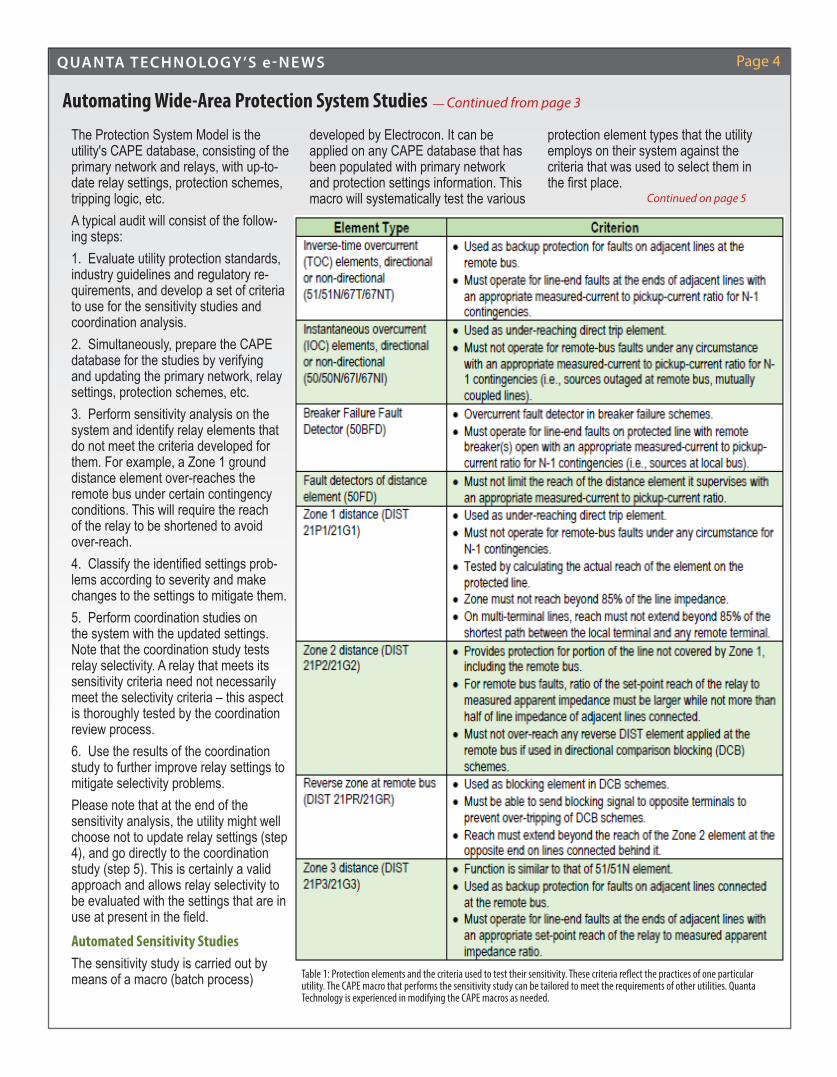
The Protection System Model is the utility's CAPE database, consisting of the primary network and relays, with up-to-date relay settings, protection schemes, tripping logic, etc.A typical audit will consist of the follow-ing steps:1. Evaluate utility protection standards, industry guidelines and regulatory re-quirements, and develop a set of criteria to use for the sensitivity studies and coordination analysis.2. Simultaneously, prepare the CAPE database for the studies by verifying and updating the primary network, relay settings, protection schemes, etc.3. Perform sensitivity analysis on the system and identify relay elements that do not meet the criteria developed for them. For example, a Zone 1 ground distance element over-reaches the remote bus under certain contingency conditions. This will require the reach of the relay to be shortened to avoid over-reach.4. Classify the identifi ed settings prob-lems according to severity and make changes to the settings to mitigate them.5. Perform coordination studies on the system with the updated settings. Note that the coordination study tests relay selectivity. A relay that meets its sensitivity criteria need not necessarily meet the selectivity criteria – this aspect is thoroughly tested by the coordination review process.6. Use the results of the coordination study to further improve relay settings to mitigate selectivity problems.Please note that at the end of the sensitivity analysis, the utility might well choose not to update relay settings (step 4), and go directly to the coordination study (step 5). This is certainly a valid approach and allows relay selectivity to be evaluated with the settings that are in use at present in the fi eld.Automated Sensitivity StudiesThe sensitivity study is carried out by means of a macro (batch process)
developed by Electrocon. It can be applied on any CAPE database that has been populated with primary network and protection settings information. This macro will systematically test the various
protection element types that the utility employs on their system against the criteria that was used to select them in the fi rst place.
Automating Wide-Area Protection System Studies — Continued from page 3
Table 1: Protection elements and the criteria used to test their sensitivity. These criteria re� ect the practices of one particular utility. The CAPE macro that performs the sensitivity study can be tailored to meet the requirements of other utilities. Quanta Technology is experienced in modifying the CAPE macros as needed.
Continued on page 5

QUANTA TECHNOLOGY’S e-NE WS Page 5
Ground Distance Zone 1 - Reach CheckThe Zone 1 ground distance element from an L-PRO relay is being tested. It is equipped with separate phase and ground overcurrent fault detectors. As can be seen from the fault detector output columns in the output above, the ratio of the pickup setting to measured current exceeds the desired ratio of 0.33. The macro reports this as a failure to meet the user-specifi ed criterion.However, the actual ratio is around 0.5, so the fault detector will not limit the distance element, even though it fails to meet the criterion. Faults with resistance might be impacted, and this will need to be tested by the user. Automated Coordination AnalysisThe coordination review evaluates the protection system as a whole, with tele-protection, reclosing and breaker failure logic, all modeled in the CAPE database. By systematically challenging the system with different contingencies like outage of primary network components, failure of teleprotection schemes, breaker failure conditions, etc., we can test the selectivity of various relay elements in the system.A CAPE macro performs the study in an automated manner. A typical coordination study on a transmission line will include the following scenarios:1. Various types of faults like Single- Line-Ground, Line-to-Line, Double- Line-Ground, and Three-Phase, with and without fault resistance.
2. User-defi ned fault locations: local close-in, 15%, 50%, 85%, and remote- close-in, or other arbitrary location.3. Outage of sources of fault current at each terminal of the study line like: a. Lines b. Generators c. Transformers d. Shunt capacitor, or inductor banks e. Grounding transformers f. Mutually coupled lines4. Outage of redundant protection schemes, one at a time.5. Outage of teleprotection schemes, one at a time.6. Failure of breaker to open.In Quanta Technology's experience, be-tween 500-700 separate fault simulations have to be performed for each transmis-sion line being studied. Obviously, this is not something that can be done manually. Automating the study is a necessity – the CAPE macro excels at this task.Two different types of output are produced by the macro:1. A summary table, with one line of output for each fault studied, and2. A detailed sequence-of-events report fi le for each fault studied, listing the relay elements that operate (or are predicted to operate) during the sequential fault clearing process.
Quanta Technology CapabilitiesThe Quanta Technology Protection & Control team is highly experienced in performing large-scale protection system audits and has worked with many utilities over the past several years. Our expertise includes:• Verifying and validating the CAPE primary network model in the database and making the necessary changes.• Adding protection system data to the CAPE database, including the modeling of LZOPs, CTs, VTs, relays, import- ing relay settings, developing contact logic codes and trip logic expressions, teleprotection schemes, breaker failure schemes, etc.• Applying the CAPE sensitivity and coordination macros to the transmission system and gathering the results.• Converting the raw output data pro- duced by the CAPE macros into more user-friendly spreadsheets that the engineer can analyze.• Classifying problems found according to severity: "Act Now", "Act Later", "Possi- ble Improvement", etc.• Making recommendations for new set- tings, to help mitigate the problems found.We welcome the opportunity to demon-strate to you the value of a protection sys-tems audit using the techniques described above.
Automating Wide-Area Protection System Studies — Continued from page 4
Table 1 shows some of the standard element types, and the criteria they must meet as per the requirements of one utility for which Quanta Technology has performed a protection system audit. Applying and testing the criteria on every element in the system is impossible to accomplish manually. The CAPE macro very elegantly automates the analysis and produces standardized output for the engineer. Here is an example of the output the macro produces:

QUANTA TECHNOLOGY’S e-NE WS Page 6
Currently there is a great need in our industry for a system-atic method for Transmission Owners to verify and document the compliance of their protection systems with the NERC PRC-023 reliability standards. Many of the methods of relay loadability evaluation currently employed, are becoming cum-bersome and costly. Quanta Technology's PRC-023 EvaltoolSM method can utilize various specialized power system protection software and customized macros to automate much of the analysis, allowing for rapid identifi cation of protection elements such as distance, overcurrent, out-of-step and switch-on-to-fault (SOTF) schemes which are non-compliant with PRC-023 loadability requirements. To facilitate analysis of large systems consisting of hundreds of transmission lines and their respec-tive protection elements, customized post-processing tools are utilized to immediately identify any non-compliance and provide customized reports for presenting complete system compliance evidence repeatedly. Ensuring compliance with PRC-023 requires an extensive review of all transmission protection schemes and settings in an effort to identify and correct any potential non-compli-ance. Transmission Owners are required to provide auditable documentation of their investigation process and evaluation methodology. Any non-compliance beyond the dates docu-mented in the standard can result in signifi cant fi nes. Due to the extensive size and complexity of the transmission systems to be reviewed, verifi cation of compliance has become a major challenge for many utilities. Automated Evaluation ProcessQuanta Technology has developed an automated post pro-cessing protection review and analysis approach – PRC-023 EvaltoolSM, to help clients identify protection elements that are non-compliant with the standard. Central to Quanta Technolo-gy's method is the use of Computer-Aided Protection Engineer-ing (CAPE) software, a power systems simulation and analysis package specializing in system protection. The transmission system and associated relay settings are modeled in CAPE, and a customized protection sensitivity analysis macro is used to compare modeled relay settings with line loading ratings to determine if non-compliance would occur. The CAPE macro has the capability to generate reports detailing distance, out-of-step, overcurrent, and SOTF evalua-tions for each individual line. To facilitate the analysis of large systems with many lines, Quanta Technology has developed a post-processing application, PRC-023 EvaltoolSM, which reads each individual line loadability analysis report from CAPE and presents the results in an easy-to-read Excel® summary table. The processed information can then be easily assessed and used to apply evaluation criteria to compile the fi nal report.
Macro Simulation & Data ProcessingFor substations that feature protective relays with enabled load blocker capability, such as load encroachment or load blinders, the analysis macro takes into consideration the protective element's trip prevention while evaluating PRC-023 non-compliance and draws additional curves to represent the blocking schemes (as exist). A typical post-processing output for PRC-023 line impedance evaluation is shown in Figure 1. It can be seen immediately that the Apple station Line 7, Zone 2 element of the SEL421 relay does not meet the PRC-023 line loading requirements. The macro has the capability to illustrate the results in the form of a coordination graphic view, which provides a visual representation of the protective elements’ characteristics and corresponding reach with respect to the boundaries of load re-gions. In Figure 2, the protection characteristics of Zone 1 and Zone 2 distance elements are drawn for each relay (SEL421 and LPRO), as well as the line loading requirement curves (representing short-term emergency (STE) and long-term emer-gency (LTE) load regions). The load encroachment curve for the SEL421 (Set A) relay and load blinder curves for the LPRO (Set B) relay are shown.It is observed that the STE line loading curve intersects with the Zone 2 curves on both relays, which would not meet the PRC-023 requirements. In this case, a load encroachment curve for Set A relay is present, but does not adequately cover the STE region. It is also set at an inadequate angle. In contrast to Set A, the load blinders for Set B relay are set to adequately block the relay tripping within the STE region and is considered a pass of the PRC-023 requirements.
Evaluation of PRC-023 Transmission Relay Loadability Requirements – PRC-023 EvaltoolSM
By Saman Alaeddini, Advisor; Ashok Gopalakrishnan, Principal Advisor; Bryan Gwyn, Senior DirectorQuanta Technology, Protection & Control
Continued on page 7
Station Line
Number LTE/STE
Rating (A) Relay Name Protective Elements
PASS Conditions
Apple Line 3 6000/4600 SEL421_A DIST "21P1" Z:1 LTE/STE Apple Line 3 6000/4600 SEL421_A DIST "21P2" Z:2 LTE/STE Apple Line 3 6000/4600 LPRO_B DIST "21P1" Z:1 LTE/STE Apple Line 3 6000/4600 LPRO_B DIST "21P2" Z:2 LTE/STE Apple Line 7 6000/4600 SEL421_A DIST "21P1" Z:1 LTE/STE Apple Line 7 6000/4600 SEL421_A DIST "21P2" Z:2 FAIL Apple Line 7 6000/4600 LPRO_B DIST "21P1" Z:1 LTE/STE Apple Line 7 6000/4600 LPRO_B DIST "21P2" Z:2 LTE/STE NOP
Banana Line 2 5625/4600 LPRO_A DIST "21P1" Z:1 LTE/STE Banana Line 2 5625/4600 LPRO_A DIST "21P2" Z:2 FAIL Banana Line 3 5625/4600 LPRO_A DIST "21P1" Z:1 LTE/STE
Figure 1. Post-processing summary table (line loadability)

QUANTA TECHNOLOGY’S e-NE WS Page 7
Post-Processing & Identi� cation of Non-ComplianceA manual evaluation of the macro output re-ports (per scheme) can be time consuming and prone to human error due to the need to evaluate a large number of line termi-nals and multiple protection elements. The PRC023 EvaltoolSM post-processing applica-tion facilitates the analysis of large systems by reading the macro output reports and ar-ranging the results in a logical (summarized) format, highlighting potential non-complianc-es. Each element of a protective relay under examination is arranged in tabular format with the evaluation verdict stated. Failed cases are highlighted in red and are readily visible along with the element that caused the violation. The PRC-023 EvaltoolSM is a user-friendly tool that sorts the raw macro output reports into a concise summarized tabular format in a few simple steps. The user can simply run thousands of PRC-023 studies using an automated script, place all the macro raw output fi les in one location, and let the post processing tool summarize all the study results in a newly created spreadsheet. The user will have the ability to create customizable reports in various formats, such as a total annual audit trail, relay specifi c feature, fi ltering by element
type, voltage, area, etc. The process fl ow chart applied by this tool is shown in Figure 3. Through the use of an automated sensitivity analysis macro, in conjunction with a report summarizing post-processing
application, the process of identifying and evaluating transmission systems for the PRC-023 compliance has been largely automated (PRC-023 EvaltoolSM). The process enables large sys-tems to be automatically an-alyzed, and auditable reports created in a fraction of the time it would take to verify each relay setting manually. The method features the speed and accuracy inherent in automated processes, as well as the advantages of reliability and repeatability in the results. The devel-oped automated evaluation process offers utilities the capability to practically eval-uate the NERC compliance requirements for large and complex transmission sys-tem facilities and categorize the action items.
PRC-023 EvaltoolSM — Continued from page 6
Figure 2. Coordination graphic output for PRC-023 violation with load encroachment.
Figure 3. Standalone Executable PRC023 EvaltoolSM Tool

QUANTA TECHNOLOGY’S e-NE WS Page 8
Designing Substation Protection & Control Systems with IEC 61850By Eric Udren, Executive AdvisorQuanta Technology, Automation & Testing
For many years now, substation protection and control engi-neers have been hearing from proponents of the international standard IEC 61850, communication networks and systems for power utility automation, about the virtues of this single interna-tionally accepted method for information exchange among relays and intelligent electronic devices (IEDs) on Ethernet networks. Product vendors have invested heavily in development - they promote the fact that there are thousands of IEC 61850 installa-tions in service around the world. There are signifi cant benefi ts for users:• Because all vendors have agreed on this single international standard for communications, it should be possible to mix products from different vendors in a scheme that has the best functions and products of each vendor.• There are several different services for information exchange, including high-speed GOOSE messaging, which can transfer binary states (such as relay trip commands or breaker status signals) among relays and IEDs connected to an optical-fi ber Ethernet local area network (LAN) at millisecond speeds - in some cases even faster than discretely wired signals. A few optical fi bers can replace thousands of wired connections. • Every logical connection can monitor itself and alert mainte- nance personnel for failures – no periodic testing is required.• IEC 61850 isn’t just a protocol specifying data points – it defi nes exchanges of standardized data models among pre- defi ned functions (logical nodes) within the IEDs. The familiar and laborious mapping of individual point connections is thus to be replaced by an engineering process that connects entire functions according to their standardized interfaces.• The Ethernet networking backbone is always able to incor-
porate the latest advances in this ubiquitous communications technology. IEC 61850 is easily combined with other commun- ications protocols and services on the same network.In spite of the benefi ts, some users report challenging exper- iences with IEC 61850 installations. Common situations include:• Diffi culties with vendors’ confi guration tools that develop the data connections and fl ows among the functions in each relay or IED, especially when products of different vendors are mixed in one design.• Problems combining devices from different vendors whose implementations of the standard do not use the same stan- dard versions or modeling features.• Troubleshooting diffi culties when the signal connections are Ethernet data messages on fi bers rather than wired discrete signals.• Inconsistent performance of Ethernet networks that are designed according to IT Department practices for enterprise networking.• Training challenges for maintenance, operating, engineering, and asset management organizations in adapting to pro- foundly new system design concepts.Of the thousands of international installations, many have been commissioned as turn-key projects from a single vendor, who may take on maintenance responsibility for a defi ned techni-cal life. North American utilities tend to take a more hands-on approach, developing their own design standards and using a mix of vendors to achieve the desired system performance in a standard that they will maintain with resources within the organization.
With GOOSE messaging, the
wiring is gone – but what happened to
the complex system functionality?
Conventional point-to-point wiring. Integrated P&C system using � ber optic network cables.
Continued on page 9
QUANTA TECHNOLOGY’S e-NE WS Page 9
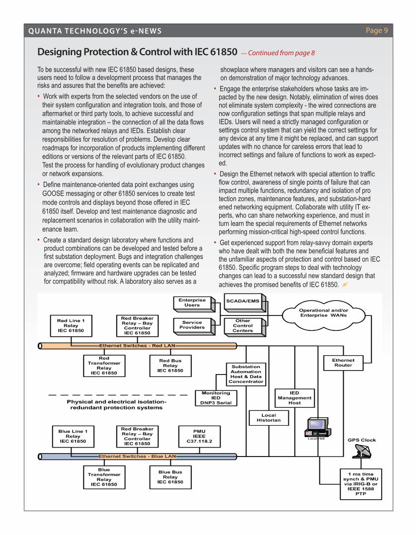
To be successful with new IEC 61850 based designs, these users need to follow a development process that manages the risks and assures that the benefi ts are achieved:• Work with experts from the selected vendors on the use of their system confi guration and integration tools, and those of aftermarket or third party tools, to achieve successful and maintainable integration – the connection of all the data fl ows among the networked relays and IEDs. Establish clear responsibilities for resolution of problems. Develop clear roadmaps for incorporation of products implementing different editions or versions of the relevant parts of IEC 61850. Test the process for handling of evolutionary product changes or network expansions.• Defi ne maintenance-oriented data point exchanges using GOOSE messaging or other 61850 services to create test mode controls and displays beyond those offered in IEC 61850 itself. Develop and test maintenance diagnostic and replacement scenarios in collaboration with the utility maint- enance team. • Create a standard design laboratory where functions and product combinations can be developed and tested before a fi rst substation deployment. Bugs and integration challenges are overcome; fi eld operating events can be replicated and analyzed; fi rmware and hardware upgrades can be tested for compatibility without risk. A laboratory also serves as a
showplace where managers and visitors can see a hands- on demonstration of major technology advances.• Engage the enterprise stakeholders whose tasks are im- pacted by the new design. Notably, elimination of wires does not eliminate system complexity - the wired connections are now confi guration settings that span multiple relays and IEDs. Users will need a strictly managed confi guration or settings control system that can yield the correct settings for any device at any time it might be replaced, and can support updates with no chance for careless errors that lead to incorrect settings and failure of functions to work as expect- ed.• Design the Ethernet network with special attention to traffi c fl ow control, awareness of single points of failure that can impact multiple functions, redundancy and isolation of pro tection zones, maintenance features, and substation-hard ened networking equipment. Collaborate with utility IT ex- perts, who can share networking experience, and must in turn learn the special requirements of Ethernet networks performing mission-critical high-speed control functions.• Get experienced support from relay-savvy domain experts who have dealt with both the new benefi cial features and the unfamiliar aspects of protection and control based on IEC 61850. Specifi c program steps to deal with technology changes can lead to a successful new standard design that achieves the promised benefi ts of IEC 61850.
Designing Protection & Control with IEC 61850 — Continued from page 8
QUANTA TECHNOLOGY’S e-NE WS Page 10
Real-Time Simulation Testing of Complex Protection Schemes - A Case StudyBy Juergen Holbach, Senior Director and Solveig Ward, Principal Advisor Quanta Technology, Automation & Testing
AbstractAs transmission networks become more complex, the design of the protection systems that provide reliable fault clearance is also becoming more complex. Real-time simulation testing offers an economical way to thoroughly test these protection schemes to ensure that a high level of dependability and security is achieved for the specifi c application. In order to ensure the reliability of a complex protection scheme based on advanced functions available in modern microprocessor relays, it is most effective to bring the actual scheme into the labo-ratory and subject the system to multiple faults and system stress scenarios in real time. This will test the protection as a system rather than its individual parts. Discovering and analyzing design issues in the laboratory before the protection scheme goes into service allows time to resolve the problem in a methodical manner, as compared to doing it under time constraints at the commissioning stage. This paper reports on the real-time digital simulation test of such a complex transmission line application. The protection schemes for two new series compensated 345 kV lines, which partially run in parallel, were tested. Each line was compensated to 50% with two series capacitors located at approximately 33% and 66% intervals of the line. In addition, each line has three shunt reactors tapped at two sepa-rate locations. The line protection systems consisted of a distance protection directional comparison blocking (DCB) scheme and two current differential line protection schemes. The DCB protection scheme and one of the line differential systems cover the entire line end-to-end. A second set of line differential systems was applied individually over the three line sections with intertrip functions between them. The line protection systems on each circuit uses a total of 11 numer-ical line protection relays with control logic developed for interaction
between them. The overall line protection systems interface with additional shunt reactor protection relays, breaker failure relays, and series capacitor bank protection systems.
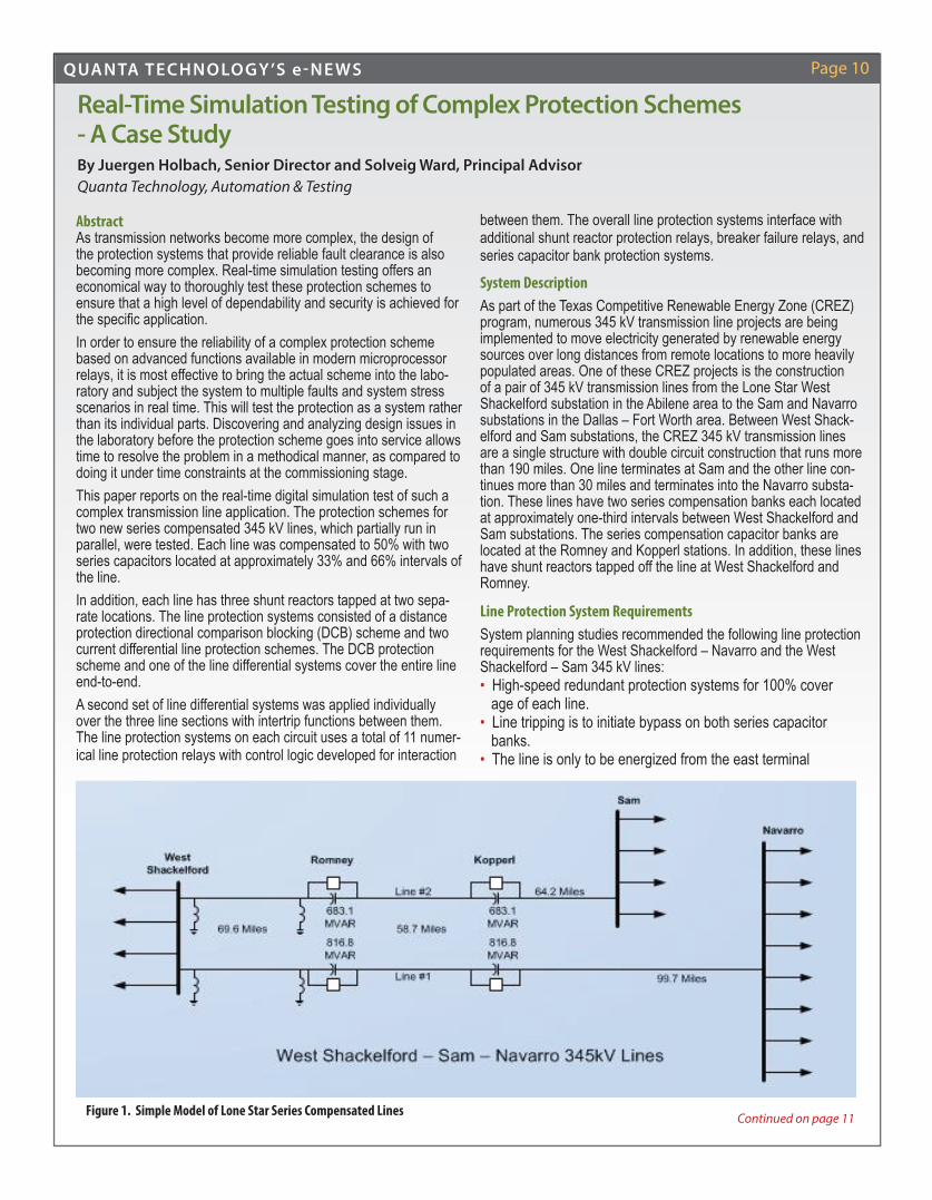
System DescriptionAs part of the Texas Competitive Renewable Energy Zone (CREZ) program, numerous 345 kV transmission line projects are being implemented to move electricity generated by renewable energy sources over long distances from remote locations to more heavily populated areas. One of these CREZ projects is the construction of a pair of 345 kV transmission lines from the Lone Star West Shackelford substation in the Abilene area to the Sam and Navarro substations in the Dallas – Fort Worth area. Between West Shack-elford and Sam substations, the CREZ 345 kV transmission lines are a single structure with double circuit construction that runs more than 190 miles. One line terminates at Sam and the other line con-tinues more than 30 miles and terminates into the Navarro substa-tion. These lines have two series compensation banks each located at approximately one-third intervals between West Shackelford and Sam substations. The series compensation capacitor banks are located at the Romney and Kopperl stations. In addition, these lines have shunt reactors tapped off the line at West Shackelford and Romney.
Line Protection System RequirementsSystem planning studies recommended the following line protection requirements for the West Shackelford – Navarro and the West Shackelford – Sam 345 kV lines:• High-speed redundant protection systems for 100% cover age of each line.• Line tripping is to initiate bypass on both series capacitor banks.• The line is only to be energized from the east terminal
Figure 1. Simple Model of Lone Star Series Compensated Lines Continued on page 11

QUANTA TECHNOLOGY’S e-NE WS Page 11
(Navarro and Sam) with series capacitors bypassed and shunt reactor switched on at West Shackelford and one shunt reactor switched on at Romney. • Line automatic reclosing only allowed for single phase to ground fault conditions.In addition, there are protection constraints to consider associated with the transmission line design. The single transmission struc-ture for the double circuit construction only allows a single OPGW path for fi ber optic communications between stations. The second communication system is required to use a physically separate path, and power line carrier was selected. The total line length is beyond typical protection relay fi ber optic communications range, which required multiplexer equipment to be located at the series compensation stations (Romney and Kopperl).
Selection of Line Protection & Control SystemsLine differential protection can provide one of the least complex schemes for series compensated lines, but needs digital commu-nications. The use of power line carriers as the second com-munication system leads to selecting a directional comparison protection scheme.The fi rst protection system to be selected was line differential relays (87L) confi gured in a three terminal application over fi ber optic communications. The Romney 87L relay subtracts the shunt reactors from the line differential protection. Also, the West Shack-elford 87L relay uses a third current input to subtract the shunt reactor from the line differential protection.The West Shackelford and Sam 87L relays also use Zone 1 and Zone 2 distance (21) protection features. The Zone 1 reach setting is based on the distance to the shunt reactor located at Romney. The West Shackelford to Navarro line 87L protection system is confi gured similarly. The 87L relay line trip is communi-cated through the fi ber multiplexer, which is also used to bypass the series capacitor banks. Series capacitor backup protection sends transfer trip back to the line terminals.The second protection system to be selected was line distance protection (21L) relays located at the West Shackelford and Sam line terminals using a DCB pilot scheme with dual communica-
tions over power line carrier and over the fi ber multiplexer system. The shunt reactor protection must start DCB carrier over both power line carrier and fi ber communications to block the line terminal distance relays from tripping for an external shunt reactor fault. The distance relays also use Zone 1 and a separate Zone 5 backup protection feature. The Zone 1 reach setting is based on the distance to the shunt reactor located at Romney. The West Shackelford to Navarro line distance protection system is confi gured similarly. The distance relay line trip is communicated through power line carrier transfer trip to bypass the series capac-itor banks. Series capacitor backup protection sends transfer trip back to the line terminals.The use of two separate series capacitor bank locations creates challenges for fault location, especially for faults occurring in the line mid-section. Line section protection was selected using a combination of three line differential protection systems (six 87L relays) to cover the three line sections. Pairs of 87L relays are used on the West Shackelford – Romney, the Romney – Kopperl, and the Kopperl – Sam line sections for an overall protection sys-tem with a total of six relays. Each line section pair of 87L relays uses direct fi ber communications with each other. The Romney and Kopperl 87L relays communicate with the other line section relay through back to back MirroredBit™ fi ber communication. An operation of the Romney 87L relay for the West Shackelford line section communicates via the adjacent Kopperl line section 87L relay to send a transfer trip back to the Sam terminal. The Rom-ney and Kopperl 87L relays also send transfer trip back to the line terminals through power line carrier transfer trip.On the West Shackelford – Romney line section, both 87L relays are connected to subtract the shunt reactors from the line differential protection. Where applicable the Zone 1 reach setting is based on the distance to the shunt reactor located at Romney. Zone 2 distance backup is used on the West Shackelford and the Sam terminal relays. The West Shackelford – Navarro line section protection relay communications had to be confi gured differently because the line distance between Kopperl and Navarro is too great for relay direct fi ber communications. The Kopperl to Navarro line section uses the multiplexer communication system.
Real-Time Simulation Testing - Case Study — Continued from page 10
Continued on page 12
Figure 2: Line Di� erential Protection System
QUANTA TECHNOLOGY’S e-NE WS Page 12
ConclusionsTypically, protection philosophies become less standardized and more customized as the application requirements grow in com-plexity. This brings challenges to developing new relay schemes and determining their settings for an application where a proven protection system design is not available. The RTDS testing of these Lone Star series compensated line protection systems was instrumental in verifying the relay functionality, scheme design, speed of operation, and improving settings. The root causes of problems found during the test are as follows:• Transient phenomena• Setting mistakes• Wrong assumptions• Unclear functional description in manual • Incorrect logic equationsThe test performed with the RTDS system had to verify the correct operation of the protection system for all possible fault scenari-os. Traditional setting tools and procedures are not suffi cient to address the complexity of the protection scheme used for this
application due to:• The complexity of the series compensated transmission line. Transient phenomena are not modeled with traditional setting tools and it is common practice that settings are verifi ed with transient simulation tools like RTDS for such applications. The complexity of the line is exuberated by it being a parallel line with a common bus at only one line end. • The complexity of the protection scheme. The series compen- sated lines are protected by a protection system that consists of 11 protection relays. All relays exchanged information with each other to perform the required protection functionality. Each of these relay has approximately 100 application relevant settings and customized logic that needed to be verifi ed by testing. To test such a system during the commissioning phase is neither practical nor economical. In an RTDS laboratory environment with automated processes, it is possible to run, evaluate and document thousands of tests in few weeks. Confi guration and setting adjust-ments can easily be done and verifi ed. The fi ndings of the tests showed the value of such an approach.
Real-Time Simulation Testing - Case Study — Continued from page 11
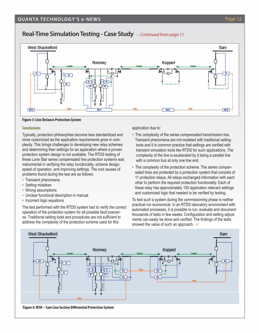
Figure 3: Line Distance Protection System
Figure 4: WSH – Sam Line Section Di� erential Protection System

QUANTA TECHNOLOGY’S e-NE WS Page 13
Quanta Technology Celebrates its
8th Anniversary!
"System Wide Coordination Analysis" by S. Alaeddini, Quanta Technology, and G. Sarkinen, Xcel Energy – CAPE Users Group Meeting, June 23-27, Ypsilanti, MI “Maximizing the Value of Sensitivity Macro” by S. Alaeddini – CAPE Users Group Meeting, June 23-27, Ypsilanti, MI "Wide-Area Protection System Studies" by A. Gopalakrishnan – CEATI International Webinar, July 10
IEEE PES General Meeting, July 27-31, National Harbor, MD: "Electrical Field Based Wireless Devices for Contactless Power Grid Phasor Measurement" (PSIM Poster Session) by Guorui Zhang "E� ects of Dependent and Common Mode Outages on the Reliability of Bulk Electric System – Part I: Basic Concepts" (PSACE Poster Session) by A. Schneider "E� ects of Dependent and Common Mode Outages on the Reliability of Bulk Electric System – Part II: Outage Data Analysis" (PSACE Poster Session) by A. Schneider "Case Studies of Experiences with Distributed Resource Interconnections on Distribution Systems" (T&D Panel Session) by L. Xu
"Accidental Islanding of Distribution Systems with Multiple Distributed Generation Units of Various Technologies" (Distribution System Modeling for PV Integration Impacts - PSACE Panel Session) by F. Katiraei "Impact of Large Scale PV Generation" (Large Scale PV Generation on Transmission and Distribution Networks - Energy Development and Power Generation Panel Session) by J. Romero Aguero "Dynamic Ramp Rate Control for Voltage Regulation in Distribution Systems with High Penetration Photovoltaic Power Generations" (Power
System Dynamic Performance - Poster session) by F. Jahanbakhsh, et. al. "Managing Asset to Achieve System Resiliency" (Natural Disaster Preparedness, Planning and Response - Super Session Panel) by B. Snyder,
D. Novosel "Smart Distribution Systems" (Tutorial) by J. Romero Aguero
"Smart Substations – Protection, Control, Communications, Wide Area Measurements, and Enterprise Applications" (Tutorial) by D. Boroughs, E. Udren
"Planning and Managing Urban Core Power Delivery Systems" by L. Willis – EUCI Course, August 4-5, Baltimore, MD "Evaluating Relay Performance during Power Swings and Associated Dynamic Events” by A. Gopalakrishnan, B. Gwyn – PAC World Americas
Conference , September 23-25, Raleigh, NC "Underground Power Distribution Systems" by L. Willis – EUCI Course, October 8-9, Atlanta, GA
QUANTA TECHNOLOGY’S e-NE WS
System Wide Coordination Analysis" by S. Alaeddini, Quanta Technology, and G. Sarkinen, Xcel Energy – CAPE Users Group Meeting, June 23-27,
Recent Quanta Technology Presentations & Publications
Eric Udren and Bryan Gwyn recently received the
Georgia Tech Walter A. Elmore Best Paper Award for "Creating a Sustainable Protective Relay Asset Strategy"
Congrats, Solveig Ward, for earning the IEEE PES Distinguished Service Award for her contributions to the Power System Relaying Committee!
IEEE Achievements: Lee Willis, Life Fellow Solveig Ward, Fellow James Blackman, Life Member
QUANTA TECHNOLOGY’S e-NE WS Page 14
Latin AmericaIn April, Quanta Technology staff presented at the CIGRE international working group on the application of robots for transmission line work in Belo Horizonte, Brazil. Dr. David Elizondo spoke on “Past experiences with ground based ro-bots and the future of applications of robots for transmission line work.” Quanta Technology was invited to present at this conference given our extensive experience with application of robots for transmis-sion line work. The conference was held in the CEMIG training center in Sete Lagos, Brasil. New and evolving technologies are already being developed and used in Brasil such as unmanned aerial vehicles, corrosion detection robots, and robots that install warning spheres.
The Quanta team recently met with XM in Colombia. Dr. Elizondo, Dr. Yi Hu and Solveig Ward pre-sented the fi nal results re-garding the Synchropha-sor Technology Roadmap for the USTDA funded Smart Grid project. XM and Quanta Technology agreed on the importance of showing the econom-ic benefi ts of applying synchrophasor technology to the electric power sector of Colombia. Three synchrophasor applications were identifi ed as key milestones to be implemented in the next three years. Quanta and XM staff also defi ned two critical components of the XM synchrophasor project--the gateways which will interface and direct data between substations and the control center, and the data bus which will serve as the data pipeline for the different actors that will participate in the project.
XM and Quanta staff also worked and published a technical article in PAC World Magazine entitled; “System Integrity Pro-tection Schemes in the Colombian Interconnected Power System” in which the results of the past defense plan roadmap for the Colombian electric system project were presented. The article discussed the current status of the electric power system
in Colombia and proposes modifi cations in the planning, protec-tion, and operational aspects. Further details about this article can be found in the PAC magazine. (http://www.pacw.org/issue/march_2014_issue/brazilian_blackout/sips.html)
The Quanta team has also been exploring new opportunities in Colombia, Ecuador, Peru and Chile regarding: • Implementation of Defense Plans Recommendations • Placement, calibration and tuning of PSS (Power System Stabilizers)• Protection Auditing • Interconnected Oil Electric System• Implementation of Intelligent Networks (Smart Grid)• Control Center Consolidation
INTERNATIONAL SPOTLIGHT
Continued on page 15
A � xed-wing unmanned aerial vehicle being developed by CEMIG and FITec.
Robot mounted in transmission line for corrosion detection.
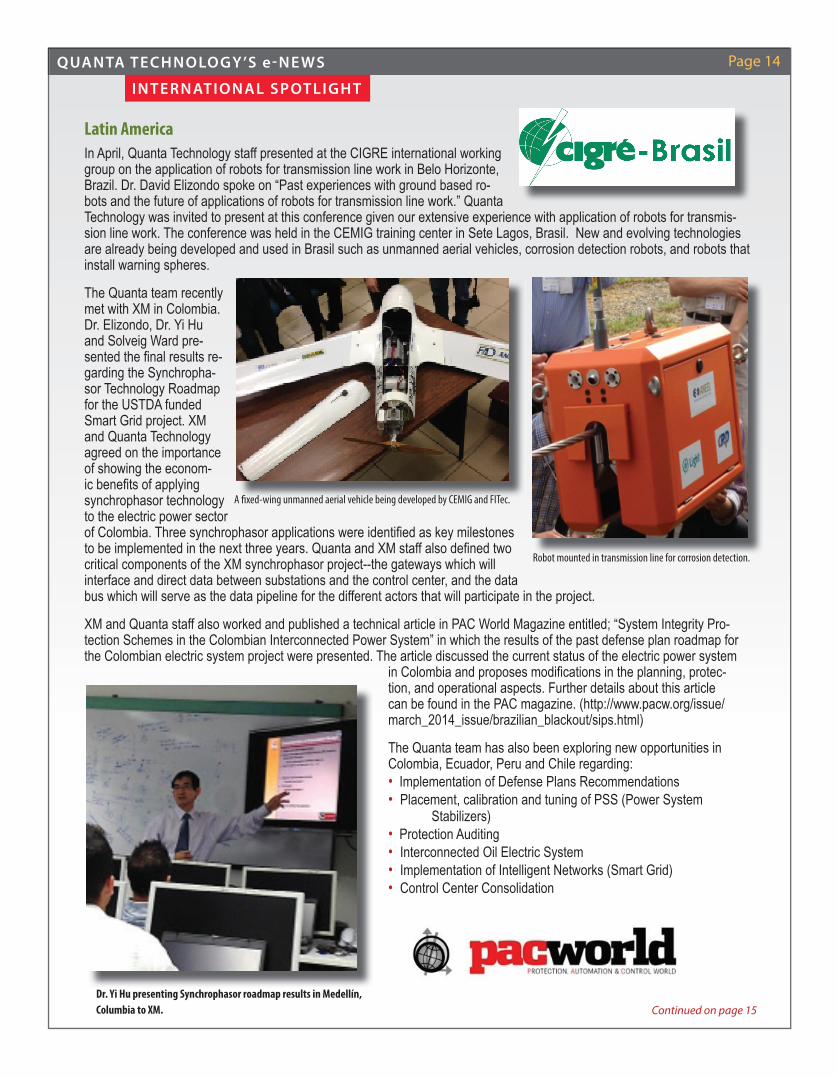
Dr. Yi Hu presenting Synchrophasor roadmap results in Medellín, Columbia to XM.

QUANTA TECHNOLOGY’S e-NE WS Page 15
Latin America Quanta Technology and representatives from our client, the Ministry of Electricity and Renewable Energy (MEER) of Ecuador participated in a four-week long Factory Acceptance Test (FAT) execution of Schneider/Telvent’s Advanced Distribution Management System (ADMS) in Seville, Spain. This ADMS system will be installed during the fourth quarter of this year in Quito and Guayaquil and will manage and operate the country's entire electric distribution system. Quanta Technology participated as the Technical Advisory Lead and acted as a third party role to witness and approve the FAT test results and provide recommen-dations.
INTERNATIONAL SPOTLIGHT — Continued from page 14
Far East Recent projects include witnessing of a Factory Acceptance Test (FAT) for a large SPS (Special Protection Scheme) in Nan-jing, China and performing RTDS testing to verify line protection schemes in Kuching, Malaysia. USTDA has recently selected Quanta Technology to participate in a Smart Grid Reverse Trade Mission for senior power sector executives from Vietnam. The delegation from Vietnam visited Quanta Technology's Raleigh offi ces on June 18. Quanta Technology continues to expand its international presence in Asia.
Quanta Technology's Ivette Sanchez and Dr. Dino Lelic in Seville, Spain with repre-sentatives from our client MEER and vendor for this project, Schneider/Telvent.
Friendship Park, Kuching, Malaysia
Quanta Technology's Ivette Sanchez and Dr. Dino Lelic in Seville, Spain with repre-
EuropeThe Quanta Technology European team has been exploring new opportunities with companies in The Netherlands and U.K., such as an Asset Life Extension project for protection relays, and an IEC 61850 application project. Also, Quanta Technology recently fi nished a business case for the application of energized work in the Netherlands for Joulz, an electric service provider in The Netherlands and for TenneT, the transmission owner for the Netherlands. A transmission tower was used as an example to explore the possibility of executing energized work in the Netherlands.

QUANTA TECHNOLOGY’S e-NE WS Page 16
WELCOME OUR NE W PEOPLE:
RECENT & UPCOMING CONFERENCES
Quanta Technology is an expertise-based, independent consult-ing company providing business and technical expertise to the energy and utility industries for deploying holistic and practical solutions that result in improved performance. Quanta Technol-ogy has grown to a client base of over 100 companies with an exceptional staff, many of whom are foremost industry experts for serving client needs.
We are a subsidiary of Quanta Services, Inc., headquartered in Houston, TX, (NYSE: PWR), member of the S&P 500, with 2012 revenue of $5.9 billion. The company is the largest specialty engineering constructor in North America, serving energy com-panies and communication utilities, according to McGraw Hill's ECN. More information is available at www.quantaservices.com.
ABOUT QUANTA TECHNOLOGY
Visit us at www.quanta-technology.com
July 14-16 Institute of Asset Management Conference, Liverpool, U.K. July 25-27 Southeastern Electric Exchange (SEE), Orlando, FL July 27-30 IEEE PES General Meeting, National Harbor, MD August 24-29 CIGRÉ, Paris, France September 8-11 IEEE PSRC Fall Meeting, Milwaukee, WI September 9-13 IEEE PES T&D Latin America, Medellin, Colombia
Robin Smoot, Proposal & Administrative Support, has more than 20 years of marketing communications, business consulting and administrative experi-ence. Robin received a MBA from Miami (Ohio) University and a Bachelor’s in Public Administration from Franklin University.
Bahman Koosha, Principal Engineer, Protection & Control, has over 8 years' programming and application development experience. He holds a Master's degree in Industrial Informatics from Skövde Univer-sity, Sweden and a Bachelor's in Electrical Engineering from Ferdowsi University, Mashhad, Iran.
Gerardo Sanchez, Senior Engineer, Distribution, recently earned his PhD in Electrical Engineering from Virginia Tech where he attended on a Fulbright Scholarship. Prior to completing his PhD, Gerardo was an Operations Engi-neer in Honduras. Gerardo will be
based in the Raleigh offi ce.
Srilalita Neti, Engineer, Protection & Control, recently earned an M.S. in Electrical and Computer Engineering from Mississippi State University where she specialized in Power Systems. Srilalita will be based in the Raleigh offi ce.
Steven Craig, Senior Advisor, Asset Opera-tions, has 15 years of experience in project management, utility operations and asset management with Carolina Power & Light, Progress Energy and Duke Energy. He holds both Bachelor's and Master's degrees in Electrical Engineering from North Carol-ina State University.
Nima Yousefpoor, Senior Engineer, Asset Operations, recently earned his PhD in Electrical Engineering from N.C. State University. He also holds both a Bachelor's and Master's in Electrical Engineering from Amirkbir University of Technology in Iran.
The Obama Administration and the Department of Energy (DOE) recently launched the U.S. Quadrennial Energy Review (QER), whose focus is to develop a comprehensive strategy for the ener-gy infrastructure. At the request of the DOE/QER team, the IEEE was requested to provide support. IEEE recruited leaders from its membership and assembled a team, led by Damir Novosel, including Veronika Rabl (Chair of the IEEE-USA Energy Policy Committee) and Jeffrey Nelson (Chair of IEEE PES Committees) to develop responses for DOE priority issues. Julio Romero Agüe-ro is also a member of the team.
IEEE LEADERSHIP