quantum analog reference manual for ho locomotives · quantum analog reference manual for ho...
TRANSCRIPT
Quantum Analog Reference Manual
for HO Locomotives
Beaverton, Oregon, 97005 November 2003
Quantum Analog Reference Manual 2/34 16 December 2003
Introduction to Quantum Analog Operation The Quantum Sound System had been designed for operation of HO locomotives using standard Analog power packs. The three most common locomotives are Steam, Diesel and Electric although others such as trolleys, power commuter cars, subway, etc. can be operated under Analog control as well. Many of the operations of Quantum equipped engines, such as turning on and off the bell, changing direction, blowing a horn or a whistle, are the same across all engine types. Unique operations or behaviors of the different types are described in the general operating instructions included with each locomotive. Currently, there are over seven Quantum locomotives released including steam, diesel and electric types.
Important Information about this Reference Manual This is a complete reference manual for analog operation of features included in the QSI Quantum system. Although your Quantum System has the ability to operate under Analog or NMRA Digital Command Control, you do not need to understand or have experience with DCC to operate your Quantum locomotive under Analog control. DCC Operation is covered separately in the Quantum NMRA DCC Reference Manual for HO Locomotives.
In addition, both the Analog and DCC Reference Manuals apply to all Quantum Locomotives, both new and old1. As new engines are introduced they may have features not found in older locomotives. Since this reference manual is a complete description of all currently available features for analog operation, check your individual instruction manual that came with your locomotive to determine which features apply to your engine. This document will evolve over time as new information is added with the purpose of making it as current and complete as possible.
This manual is divided into four sections.
• the first part will provide the necessary information to have you up and running all features of your locomotive in five minutes.
• the second part of this reference manual describes programming your engine.
• the third section gives detailed instructions on programming each option and
• the forth section describes special operations and features.
Programming under Analog operation is separate from DCC programming and is very easy to do from your standard Analog power pack. However, we suggest you get used to operating and having fun with your locomotive before exploring its programming options described in sections two and three.
1 The one exception is the Broadway Limited Hudson which uses a different method for programming in Analog.
Quantum Analog Reference Manual 3/34 16 December 2003
1. Locomotive Operation under Analog Control 1.1 Getting Started Use an HO power pack with a standard direction switch2 (see recommended power packs in Appendix II). Set the direction switch to run in forward.
• Turn the throttle up slowly until you hear the Quantum System come on with air let-off, air pumps, blower hiss and the dynamo revving as the headlight comes up to its “dim” setting.
• Continue to turn up the throttle and move the locomotive out slowly in forward with the steam locomotive’s chuffing in sync with the motion of the drive wheels or diesel motor sounds revving up: All prime mover sounds are proportional to the engine’s loading (see QSI Sound of Power® on page 8). The headlight will come on bright.
• As you slow the engine down by gradually reducing the throttle, the locomotive will produce lighter chuff or motor laboring and squealing brake sounds will occur as the locomotive comes to a stop.
Note: The Quantum System requires that the throttle be turned up a little higher than ordinary HO locomotives before the engine will move out from its neutral state. If you need to turn your throttle up quite high to start your HO locomotive, the Quantum System can be adjusted for operation with your particular power pack (see Analog Programming on Page 6-7). For recommended power packs, see Appendix II.
Note: Brake sounds come on at about 10 smph with continuing sounds for about six seconds to model the locomotive coming to a slow stop. If the engines stops quickly after the brake sounds start, the brake sounds will terminate immediately.
1.2 Reversing the Locomotive This simple operation is exactly the same as it is with standard engines.
• Bring the engine to a stop and turn the power all the way off with the throttle. • Flip the direction switch and reapply power to go in the other direction.
Track Polarity Determines Engines Direction Although Quantum uses the direction switch as a remote control signal, we still adhere to the standard that the locomotive’s direction is determined by the applied track polarity when the engine starts out. A stopped locomotive will always start out in the same direction as other engines on your layout based on the polarity on the track. If the locomotive was blowing its whistle when power was shut down, it will restart from its stopped position in the opposite direction with the whistle not blowing. However, if a moving engine with whistle blowing stutters briefly from a power interrupt, it will not change direction and the whistle will continue to blow. This will prevent a moving engine with whistle blowing from abruptly changing direction because of momentary power loss from a faulty turnout or dirty track.
2 If your power pack does not have a direction switch, use the HO DC SideKick controller that can be easily added to any existing power pack for Horn, Bell, and Programming control. See Appendix IV for a complete description of the HO DC SideKick product.
Quantum Analog Reference Manual 4/34 16 December 2003
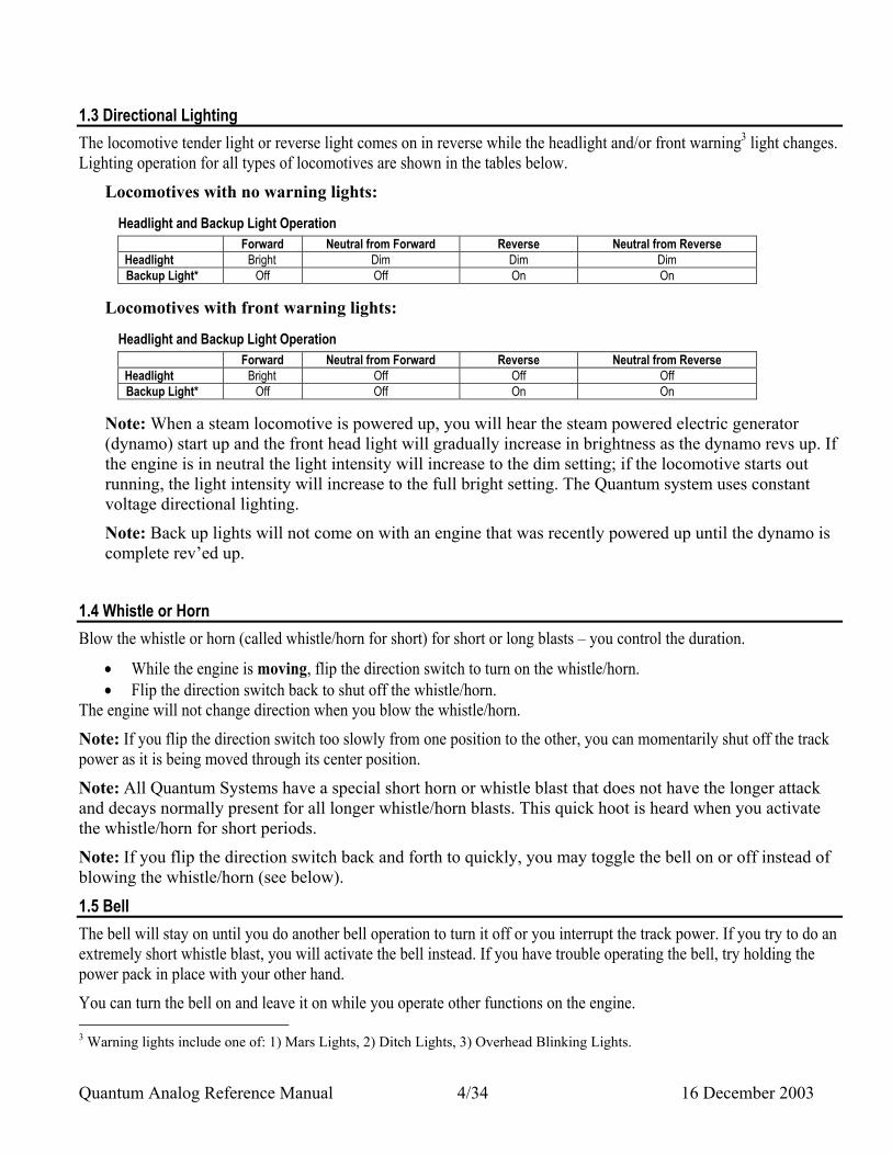
1.3 Directional Lighting The locomotive tender light or reverse light comes on in reverse while the headlight and/or front warning3 light changes. Lighting operation for all types of locomotives are shown in the tables below.
Locomotives with no warning lights:
Headlight and Backup Light Operation Forward Neutral from Forward Reverse Neutral from Reverse
Headlight Bright Dim Dim Dim Backup Light* Off Off On On
Locomotives with front warning lights:
Headlight and Backup Light Operation Forward Neutral from Forward Reverse Neutral from Reverse
Headlight Bright Off Off Off Backup Light* Off Off On On
Note: When a steam locomotive is powered up, you will hear the steam powered electric generator (dynamo) start up and the front head light will gradually increase in brightness as the dynamo revs up. If the engine is in neutral the light intensity will increase to the dim setting; if the locomotive starts out running, the light intensity will increase to the full bright setting. The Quantum system uses constant voltage directional lighting.
Note: Back up lights will not come on with an engine that was recently powered up until the dynamo is complete rev’ed up.
1.4 Whistle or Horn Blow the whistle or horn (called whistle/horn for short) for short or long blasts – you control the duration.
• While the engine is moving, flip the direction switch to turn on the whistle/horn. • Flip the direction switch back to shut off the whistle/horn.
The engine will not change direction when you blow the whistle/horn.
Note: If you flip the direction switch too slowly from one position to the other, you can momentarily shut off the track power as it is being moved through its center position.
Note: All Quantum Systems have a special short horn or whistle blast that does not have the longer attack and decays normally present for all longer whistle/horn blasts. This quick hoot is heard when you activate the whistle/horn for short periods.
Note: If you flip the direction switch back and forth to quickly, you may toggle the bell on or off instead of blowing the whistle/horn (see below).
1.5 Bell The bell will stay on until you do another bell operation to turn it off or you interrupt the track power. If you try to do an extremely short whistle blast, you will activate the bell instead. If you have trouble operating the bell, try holding the power pack in place with your other hand.
You can turn the bell on and leave it on while you operate other functions on the engine. 3 Warning lights include one of: 1) Mars Lights, 2) Ditch Lights, 3) Overhead Blinking Lights.
Quantum Analog Reference Manual 5/34 16 December 2003
• Turn the bell on with a Quick flip-and-back operation of the direction switch. • Turn the bell off with a second Quick flip-and-back operation of the direction switch.
When you toggle4 the bell off, it will continue ringing for a few seconds to mimic the prototype swinging motion of steam engine pull bells slowing down slowing down or the pneumatic mechanically operated clapper striking a few more times with progressively less force.
Note: The bell will stay on until you do another Quick operation of the direction switch to turn it off, or you interrupt the track power. If you do a Slow flip-and-back operation, you will get a short whistle or horn hoot instead of the bell. If you try to do a very short whistle/horn blast using a Quick operation, you will activate the bell instead. If you have trouble doing the Quick flip-and-back operation, try holding the power pack in place with your other hand to keep the unit from slipping. If you still have difficulty with the Quick and Slow Operations, use the HO DC SideKick add on Analog controller to your power pack.
1.6 Doppler Effect
This great effect makes the characteristic change in tone as the engine passes.
• While the engine is moving towards the observer, flip the direction switch to turn on the horn or whistle. • Wait at least one second while the whistle/horn is blowing • Flip the direction switch back and forth quickly so the whistle does not shut off. This will not turn on the bell.
Instead you will hear the whistle/horn and engine sounds shift in pitch as the locomotive passes by. • Either flip the direction switch back to shut of the whistle/horn, or continue with long or short hoots. When you
are finished blowing the whistle/horn, the engine sounds will automatically return to normal after a few seconds. If the Bell was on, it will shut off.
Note: All engine sounds will shift in frequency when you activate the Doppler effect, including the bell (if previously turned on). You can also continue to blow the whistle/horn after the Doppler shift operation and it will stay at the lower pitch. After a few seconds of not blowing the whistle/horn, the bell will shut off (if on) and all sounds will return to normal. The bell is shut off at the end of the Doppler operation since the bell sounds very odd and non-prototypical as it changes its tone and character during the period the engine sounds are returning to normal.
1.7 Neutral In Neutral, the engine will continue to make prototypical sounds appropriate to its resting state.
• Enter neutral by simply turning the throttle down but not off until the engine stops moving. The headlight dims in neutral, which was a common practice with prototype steam locomotives.
• You will hear a short air release when the engine stops moving and a longer air release about three seconds later followed by air pump and other background sounds.
• After the pumps starts, you can also use the direction switch to blow the whistle/horn or turn on or off the bell.
Note: If a Quantum diesel locomotive is left in Neutral after Reverse, special Low Idle diesel motor sounds will automatically come on after 30 seconds (see description of Low Idle in Appendix I, section 2.1).
If you cannot enter neutral, or have difficulties with any of the operations, you may need to program your locomotive for optimal use with you particular power pack; this is explained fully in the next section under Analog Programming.
1.8 Changing Engine Direction Without Turning off the Sound
You can use the power pack’s direction switch while the locomotive is in neutral to change the engine's direction. 4 “toggle” means to switch from one setting or position to another (e.g. you toggle the bell from on to off and you toggle the bell from off to on).
Quantum Analog Reference Manual 6/34 16 December 2003
• Put the engine in neutral by bringing the engine to a stop. • Flip the direction switch after you hear the short air release but before the longer air release and the pump
sounds come on. During this short time (3 seconds) the whistle will not blow when you change the direction switch.
• Turn up the throttle to operate the engine in the opposite direction.
If you have waited until the pumps start in neutral and now wish to change direction, you can either:
1. Turn the power all the way off, change the direction switch and turn the power back on, or 2. Flip the direction switch (the whistle/horn will come on) and then turn up the throttle (when the engine starts to
move, the whistle will stop). If you are using an HO Power Pack equipped with a Pulse Drive Switch, please see Appendix IIa.
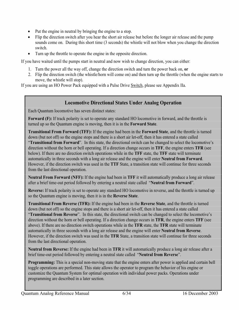
Locomotive Directional States Under Analog Operation Each Quantum locomotive has seven distinct states:
Forward (F): If track polarity is set to operate any standard HO locomotive in forward, and the throttle is turned up so the Quantum engine is moving, then it is in the Forward State.
Transitional From Forward (TFF): If the engine had been in the Forward State, and the throttle is turned down (but not off) so the engine stops and there is a short air let-off, then it has entered a state called “Transitional from Forward”. In this state, the directional switch can be changed to select the locomotive’s direction without the horn or bell operating. If a direction change occurs in TFF, the engine enters TFR (see below). If there are no direction switch operations while in the TFF state, the TFF state will terminate automatically in three seconds with a long air release and the engine will enter Neutral from Forward. However, if the direction switch was used in the TTF State, a transition state will continue for three seconds from the last directional operation.
Neutral From Forward (NFF): If the engine had been in TFF it will automatically produce a long air release after a brief time-out period followed by entering a neutral state called “Neutral from Forward”.
Reverse: If track polarity is set to operate any standard HO locomotive in reverse, and the throttle is turned up so the Quantum engine is moving, then it is in the Reverse State.
Transitional From Reverse (TFR): If the engine had been in the Reverse State, and the throttle is turned down (but not off) so the engine stops and there is a short air let-off, then it has entered a state called “Transitional from Reverse”. In this state, the directional switch can be changed to select the locomotive’s direction without the horn or bell operating. If a direction change occurs in TFR, the engine enters TFF (see above). If there are no direction switch operations while in the TFR state, the TFR state will terminate automatically in three seconds with a long air release and the engine will enter Neutral from Reverse. However, if the direction switch was used in the TFR State, a transition state will continue for three seconds from the last directional operation.
Neutral from Reverse: If the engine had been in TFR it will automatically produce a long air release after a brief time-out period followed by entering a neutral state called “Neutral from Reverse”.
Programming: This is a special non-moving state that the engine enters after power is applied and certain bell toggle operations are performed. This state allows the operator to program the behavior of his engine or customize the Quantum System for optimal operation with individual power packs. Operations under programming are described in a later section.
Quantum Analog Reference Manual 7/34 16 December 2003
Note: Neutral or Transitional states are entered automatically whenever a powered locomotives come to a complete stop. This can occur when the throttle is reduced to low setting as described above. It can also occur if an engine stalls on a grade or encounters some hindrance that results in the engine stopping.
1.9 Operating Standard DC Powered Locomotives with Quantum Equipped Locomotives Although the polarity on the track will cause both standard HO and Quantum equipped locomotives to operate in the same direction, we do not recommend using mixed type of locomotives in the same consist for two reasons.
1. The Quantum equipped engine requires higher track voltage to activate the electronics than is required to start most standard HO locomotives. The factory default for starting a Quantum engine is 8.5 volts while most modern standard HO engines only require 1-3 volts to start moving. Although Quantum engines can be programmed to start at lower voltages, we do not recommend trying to set the Vstart5 voltage lower than 5 volts. This difference in voltage will cause the standard engine and the Quantum engine to have unequal power when used in most consists.
2. Operating your whistle/horn or bell while your mixed consist is moving will cause some undesirable effects in Standard HO locomotives. Your Quantum locomotive, of course, will blow its whistle/horn and will not change direction but the standard engine will change direction abruptly. Even toggle the bell on or off will cause the standard engine to briefly change direction back and forth in a non-prototypical manner.
If you able to get your Quantum and standard engine to match speed using Vstart and Vmax, you can operate your locomotives together, but make sure your consist is in neutral where sudden polarity reversals will not affect standard locomotive operation. 1.10 Engine Inertia and Regulated Throttle Control (RTC) You can set your Quantum equipped engine to have any of 16 different inertia6 levels (see Analog Programming in next section). Level 0 is the default, which is no inertia. At this setting your engine will accelerate or stop as quick as the internal flywheel will allow. For any inertia from 1-15, your Quantum locomotive will take longer to change speed. At level 1, it will take approximately 5 seconds to achieve full speed at max throttle7; at level 15, it will take over 3 minutes to achieve full speed. In addition, at higher inertia settings, your engine will decelerate more slowly as you decrease your throttle. 1.11 Sound of Power 5 Some pulse drive power packs like certain models of the Tech II can work with a lower Vstart and may be suitable for operation
with HO standard engines in consists. If you cannot program Vstart below 5 volts, then you do not have a pulse drive power pack.
6 Inertia effects are often referred to a momentum. However, inertia is the correct term to describe an objects tendency to remain at rest or remain in motion.
7 Some unloaded power packs produce excessive voltage at max throttle and will activate the Quantum high voltage circuit breaker. When this happens, your engine will stop and emit a series of hoots until the power is turned down (see Troubleshooting, Appendix III)
Quantum Analog Reference Manual 8/34 16 December 2003
If you have selected any of the inertia settings from level 2 to 15, the engine will produce Sound of Power™ effects while the engine is accelerating or decelerating. Once the engine has achieved its final speed, it will produce standard chuff or diesel motor sounds appropriate to the throttle setting. 1.12 Manual Volume Adjustment Volume can be adjusted manually using the volume control in the tender or diesel body or electronically using the programming methods described in the section Analog Programming. To adjust the volume manually,
• Locate the access to the volume control.
Note: On steam engines, it is often the tender water hatch. Access is gained by pulling the hatch straight up and off from the tender roof.
• Insert a small screwdriver into the access hole until the blade contacts the volume control.
• Turn the screwdriver in the clockwise direction to increase volume and in the counterclockwise direction to lower the volume.
Quantum Analog Reference Manual 9/34 16 December 2003
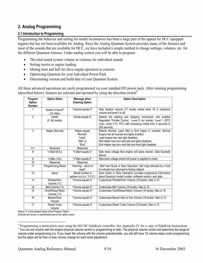
2. Analog Programming 2.1 Introduction to Programming Programming the behavior and setting for model locomotives has been a large part of the appeal for DCC equipped engines but has not been available for Analog. Since the Analog Quantum System provides many of the features and most of the sounds that are available for DCC, we have included a simple method to change settings, volumes, etc. for the different Quantum features. Under analog control you will be able to program:
• The total sound system volume or volumes for individual sounds • Setting inertia or engine loading. • Muting horn and bell for slave engine operation in consists. • Optimizing Quantum for your individual Power Pack • Determining version and build date of your Quantum System
All these advanced operations are easily programmed via your standard HO power pack. After entering programming (described below), features are selected and operated by using the direction switch8.
Program Option Number
Option Name Message when Entering Option
Option Description
1 System Volume9 (16, Max)
“Volume equals X” Sets System volume (17 levels) where level 16 is maximum volume and level 0 is off.
2 Inertia (0, No Inertia)
“Inertia equals X” Selects the starting and stopping momentum and enables Regulated Throttle Control. Level 0 (no inertia), Level 1 (RTC only), Level 2-15, RTC with increasing inertia from 5 seconds to 200 seconds.
3 Helper (Normal)
Helper equals “Normal”, “Lead”, “Mid” or “End”
Selects Normal, Lead, Mid or End helper in consists. Normal Engine has all sounds and lights enabled. Lead engine has rear light disabled, Mid Helper has horn and bell and lights disabled, End Helper has horn and bell and front light disabled.
4-7 Reserved Reserved 8 V-Start (8.5v) “V-Start equals X” Sets track voltage that engine will leave neutral. (See Example
below) 9 V-Max (12v) “V-Max equals X” Sets track voltage where full power is applied to motor. 10 Reserved Reserved 11 Programming Reset “Warning – about to
reset” After next Quick or Slow Operation, bell rings followed by a hoot to indicate loco returned to factory default.
12 About Model number is spoken out (i.e. “3 0 0”)
Each Quick or Slow Operation provides progressive information about Quantum model number, software version, and date.
13 Whistle/Horn Volume (11)
“Volume equals X” Customizes Whistle/Horn Volume (16 levels). Max is 15.
14 Bell Volume (11) “Volume equals X” Customizes Bell Volume (16 levels). Max is 15. 15 Chuff/Diesel Motor
Volume (11) “Volume equals X” Customizes Chuff/Diesel Motor Volume (16 levels). Max is 15.
16 Blower/Fans Volume
“Volume equals X” Customizes Blower Hiss or Fan Volume (16 levels). Max is 15.
17 Diesel Turbo Volume
“Volume equals X” Customizes Diesel Turbo Volume (16 levels). Max is 15.
Where “x” is the present value of the Program Option Defaults are shown in parenthesis next to the option name.
8 Programming is particularly easy using the HO DC SideKick controller. See Appendix IV for a copy of SideKick Instructions. 9 You can set volume with the engine physical volume control or programming or both. The physical volume control will determine the range of volume under programming (i.e. If you lower the volume with the volume potentiometer, you will still have 16 volume steps under programming but the steps will be finer or less volume change for each level adjustment.
Quantum Analog Reference Manual 10/34 16 December 2003
2.2 Entering Programming There is a simple sequence to enter programming using the direction switch.
• Apply power and turn up the throttle to hear the sound system come on10.
• Within five seconds of powering up, turn the bell on with a Quick flip-and-back operation of the direction switch.
• Within three second of the bell turning on, turn the bell off with a second Quick flip-and-back operation of the direction switch.
• Within three seconds, turn the bell back on with a third Quick flip-and-back operation of the direction switch.
Note: You have done this correctly if you have moved the direction switch three times in one direction and three times in the other direction. If you delay too long after power has been first applied, the opportunity to enter programming will time out and you will need to start again by shutting off and reapplying track power. If you have difficultly with Quick flip-and-back operations, holding the power pack steady with the other hand may help.
• Once you perform the three bell operations after applying power, the bell should be on. After about three seconds, the bell and all locomotive sounds will shut off automatically. You will hear the phrase “Enter Programming” followed by silence. The headlight and backup light (if your engine is equipped with one) will start blinking alternately on and off at a one second rate.11 You can now start to navigate through the Programming Options. The lights will continue to flash as long as the locomotive is being programmed.
Note: The reason for the unusual procedure for entering programming is to prevent it from accidentally happening during normal operation.
Note: If you are having any problems programming your Quantum engine with your power pack, please check recommended power packs listed in the appendix.
2.3 Scrolling through the Program Options • After entering programming, you will hear an announcement of the first programming option,
“System Volume” followed by the announcement “Option 1 – System volume”.
• To access other options, simply flip the direction switch to the opposite position and leave it there. Listen as each option number is announced in order.
• Flip the switch back when you wish to stop at a particular option. After you stop at an option you will hear the option’s name announced. When you are scrolling through and stopping at Program Options, you are not making any changes. To make changes you must actually enter the option.
• To continue on through other options, flip the direction switch again to the opposite position and leave it there while each option number is announced starting at your current option number. Once
10 It is not a requirement but you may want to leave the throttle low enough that the engine does not move. If your locomotive is moving, it will stop once you enter programming. 11 Some very early Quantum engines may not have blinking lights. The lack of this feature does not affect programming.
Quantum Analog Reference Manual 11/34 16 December 2003
you reach the highest number option, the system will automatically return to the first option and start counting from there.
The Quantum system will respond with two numbers spoken out for options of ten and above ( e.g. “one three” means thirteen).
Note: If you accidentally go to a higher number programming option other than the one you wanted, simply turn the power off, re-enter programming and start again or you can scroll forward until the counter starts again at the beginning.
Note: If you get lost in adjusting the different Programming Options or do not like your settings and wish to return to the factory defaults, you can do so using Programming Option #11 (see below).
2.4 Leaving Programming
• You can exit Programming anytime you want by turning the power off and back on again.
2.5 Entering an Option
• After hearing the announcement of the option, use either a Quick or a Slow operation with the direction switch to enter that option. You will hear the message announcing that option and its current setting (see column three in table above). Entering an option does not change the settings for that option. For unused options, you will hear “Reserved”. For any volume option, you will hear “Volume equals X” (where “X” is its present level setting). After a moment, you will hear the sound playing at its current volume setting.
The Quantum system will respond with two numbers spoken out for settings of ten and above ( e.g. “one zero” means ten).
Note: Entering a programming option does not change the settings for that option; it only provides information about its current value.
How to do Quick or Slow Operations There are two ways to use the direction switch called “Quick” and “Slow”. Quick is a quick flip-and-back, used for turning on the bell under normal operation, while the Slow is a slightly slower action of flip-and-back that is used for a whistle hoot under normal operation. These two types of operations are also used in programming.
As an aid to know that you have flipped the direction switch during programming, you will hear a soft hiss when you have flipped it one way. When you flip the direction switch back, the hiss sound ends.
If you flip the direction switch back and forth so fast that you do not hear the hiss at all, it is a Quick operation. If you hear the hiss before you flip it back, it is a Slow operation.
During programming, it makes no difference which position the direction switch is in prior to doing the Quick or Slow operation.
Quantum Analog Reference Manual 12/34 16 December 2003
2.6 Making Changes to the Option
• Use Slow or Quick flip-and-back operations to program new settings as described in the above table. For all level adjustments, a Quick operation will decrease one level while a Slow operation will increase one level.
• You can leave an option by advancing to the next option or by leaving programming. Use an up and down motion of the throttle to advance or turn the power off to leave programming.
Note: When you leave an option by flipping the direction switch to advance to the higher options, Quantum will first announce the option you are in and then precede to higher numbers.
Note: Since “System Volume” is the first option, you can use Quick or Slow operations immediately after entering programming to change the volume.
3 Feature Programming Options Each of the following subsections provides compete instructions for individual feature programming. You must be familiar with how to enter programming or know how to do a Slow or Quick operation with the power pack reverse switch.
Do not be concerned about making mistakes. Programming is set up to always allow you to recover from incorrect settings. Even if you cannot remember what you have done, you can always reset all features to factory values through one of the programming options or by using the hardware jumper on the circuit board (described in section 4.1).
3.1System Volume (option 1) This option allows the user to increase or decrease the overall sound system volume. This setting affects all sounds at once. Individual sounds can be adjusted separately in other programming options. (see options 13-16 below).
1. Enter the programming mode. You will hear “Enter Programming” followed by “Option one – System volume”.
2. Use either a Quick or a Slow flip-and-back operation of the direction switch to enter this option. You will hear an ensemble of engine sounds at the current volume level.
3. Use a Quick operation with the direction switch, you will hear the ensemble play again at the next lower volume setting. Continue to use Quick operation to decrease the volume level. At the lowest level, some or all of the ensemble sounds may fade out.
4. Use a Slow flip-and-back operation of the direction switch to increase the volume to the next level. If you perform a Slow flip-and-back operation at the highest level, the volume will not change from this setting.
5. To leave programming, interrupt the power by turning the throttle off, and then power up for usual engine operation.
6. Or continue to higher programming options by flipping the direction switch to the opposite position and leave it there. Wait as the option numbers count up in order.
Quantum Analog Reference Manual 13/34 16 December 2003
In total, there are 16 volume levels at 2 db decrements with level 17 (0 db) as the loudest and level 1 (-32db) as the lowest (which is essentially off). The factory setting for System Volume is at level 17 (0 db).
Note: the verbal programming responses (such as “Enter Programming” etc.) have a minimum volume setting to allow programming even when the system volume is turned all the way off.
Note: If you intend to program the volume electronically, you may first want to turn the manual volume up all the way. This will give you the greatest range of volume programming. Or you may wish to limit the maximum volume you can program, to provide the best sound quality. To do this, first program the volume to the highest level and then use the manual adjustment to set it at its highest desirable setting.
3.2 Inertia (option 2) This option is useful for providing on-board inertia and prevents the engine from accelerating or decelerating quickly. The higher the Inertia level, the longer it will take to reach full speed or to slow to a stop. All inertia effects are governed by a motor control feature called “Regulated Throttle Control” (or RTC). Under RTC, as you increase track voltage, the motor is provided a portion of that power which, depending on the inertia setting, will gradually accelerate the locomotive more realistically until it reaches full speed. RTC will also allow you to run your locomotives very slowly without concern that it will abruptly stop from minor impediments such as misaligned track joints, tight curves, rough switches, etc. RTC operates your engine as though it has massive inertia; your engine will resist changes in speed once it is moving and will resist starting up quickly if it as rest. For instance, if your Quantum equipped locomotive, with RTC on, encounters a grade, it will eventually slow down. Providing more throttle will slowly accelerate it back to speed. RTC and inertia settings also affect how your engine decelerates. You can, however, cause your engine to brake under deceleration by bringing the throttle down quickly since this reduces the available power to the system and forces the speed to decrease faster than RTC or Inertia would normally allow.
1. Enter the programming mode. You will hear “Enter Programming” followed by “Option one – System volume”.
2. Flip the direction switch to the opposite position and leave it there. Flip the direction switch back when you hear “Option two”. You will then hear “inertia”.
3. Use either a Quick or a Slow flip-and-back operation of the direction switch to enter this option. You will hear “inertia equals X” where X is the current value of the inertia.
4. Use the direction switch in Slow operations to increase the inertia setting up to a maximum of 15. Use a Quick operation of the direction switch to lower the inertia setting. Each new setting will be spoken out.
5. To leave programming, interrupt the power by turning the throttle off, and then power up for usual engine operation.
6. Or continue to higher programming options by flipping the direction switch to the opposite position and leave it there. Wait as the option numbers count up in order.
Quantum Analog Reference Manual 14/34 16 December 2003
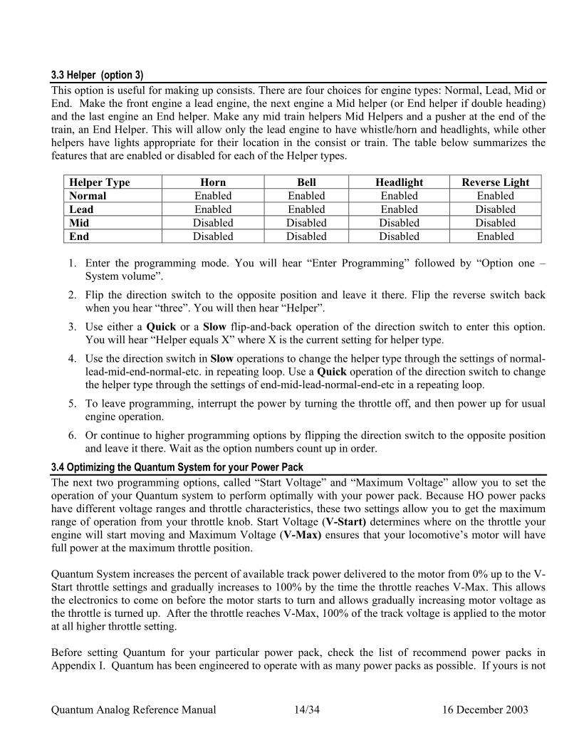
3.3 Helper (option 3) This option is useful for making up consists. There are four choices for engine types: Normal, Lead, Mid or End. Make the front engine a lead engine, the next engine a Mid helper (or End helper if double heading) and the last engine an End helper. Make any mid train helpers Mid Helpers and a pusher at the end of the train, an End Helper. This will allow only the lead engine to have whistle/horn and headlights, while other helpers have lights appropriate for their location in the consist or train. The table below summarizes the features that are enabled or disabled for each of the Helper types.
Helper Type Horn Bell Headlight Reverse Light Normal Enabled Enabled Enabled Enabled Lead Enabled Enabled Enabled Disabled Mid Disabled Disabled Disabled Disabled End Disabled Disabled Disabled Enabled
1. Enter the programming mode. You will hear “Enter Programming” followed by “Option one –
System volume”.
2. Flip the direction switch to the opposite position and leave it there. Flip the reverse switch back when you hear “three”. You will then hear “Helper”.
3. Use either a Quick or a Slow flip-and-back operation of the direction switch to enter this option. You will hear “Helper equals X” where X is the current setting for helper type.
4. Use the direction switch in Slow operations to change the helper type through the settings of normal-lead-mid-end-normal-etc. in repeating loop. Use a Quick operation of the direction switch to change the helper type through the settings of end-mid-lead-normal-end-etc in a repeating loop.
5. To leave programming, interrupt the power by turning the throttle off, and then power up for usual engine operation.
6. Or continue to higher programming options by flipping the direction switch to the opposite position and leave it there. Wait as the option numbers count up in order.
3.4 Optimizing the Quantum System for your Power Pack The next two programming options, called “Start Voltage” and “Maximum Voltage” allow you to set the operation of your Quantum system to perform optimally with your power pack. Because HO power packs have different voltage ranges and throttle characteristics, these two settings allow you to get the maximum range of operation from your throttle knob. Start Voltage (V-Start) determines where on the throttle your engine will start moving and Maximum Voltage (V-Max) ensures that your locomotive’s motor will have full power at the maximum throttle position. Quantum System increases the percent of available track power delivered to the motor from 0% up to the V-Start throttle settings and gradually increases to 100% by the time the throttle reaches V-Max. This allows the electronics to come on before the motor starts to turn and allows gradually increasing motor voltage as the throttle is turned up. After the throttle reaches V-Max, 100% of the track voltage is applied to the motor at all higher throttle setting. Before setting Quantum for your particular power pack, check the list of recommend power packs in Appendix I. Quantum has been engineered to operate with as many power packs as possible. If yours is not
Quantum Analog Reference Manual 15/34 16 December 2003
listed in our table, you can still go through the steps to optimize your power pack with the Quantum sound system. If there are still difficulties in operation after you have completed these steps, then we suggest you use one of the recommended power packs. 3.4.1 V-Start (option 8) This will determine the throttle setting where your engine will start to move out of neutral.
1. Enter the programming mode. You will hear “Enter Programming” followed by “Option one – System volume”.
2. Flip the direction switch to the opposite position and leave it there. Flip the reverse switch back when you hear “eight”. You will then hear “V-Start”.
3. Use either a Quick or a Slow flip-and-back operation of the direction switch to enter this option. You will hear “V-Start equals X” where X is the current voltage setting for V-Start.
4. Use the direction switch again in either a Quick or Slow operation. You will hear “Set throttle to V-Start”.
5. Move the throttle to where you want to leave neutral and leave it there. After three seconds you will hear the voltage track voltage measurement for this throttle setting (e.g. “five point three volts” which would mean the track voltage is 5.3 volts). Move the throttle to any new setting and wait for a new measurement. The voltage measurement will continue to be spoken out about every 2-3 seconds.
Note: To ensure proper operation of the Quantum system, you should set the throttle for 5 volts or more. For voltages lower than five volts, it may take some time to compute the V-Start setting.
6. Use the direction switch again with either a Quick or Slow operation or start the V-Start procedure. The bell will start ringing continually, indicating the process is calculating the correct value of throttle setting. At the end of the process, the engine will move slightly and stop. The whistle will hoot, signifying the end of the operation. You will hear “V-Start equals X” where X is the new setting.
Note: Sometimes it is difficult to see the engine move unless you are watching carefully.
Note: The final calculation for V-Start is always lower than the voltage measurement. This is because the engine draws power during the process of setting the voltage, which will lower the track voltage. If this voltage is too low, enter this option again by flipping the reverse switch to the opposite position and leaving it there. When will hear, Option 8, flip the reverse switch back. You have now re-entered the V-Start Option. Go through the same procedure outlined above but this time set the throttle higher.
7. To leave programming, interrupt the power by turning the throttle off, and then power up for usual engine operation.
8. Or continue to higher programming options by flipping the direction switch to the opposite position and leave it there. Wait as the option numbers count up in order.
3.4.2 V-Max (option 9)
Quantum Analog Reference Manual 16/34 16 December 2003
The V-Max procedure sets the Quantum System motor drive to apply full power close to your maximum throttle voltage. V-Max default is set at 14 volts dc. Some power packs do not go up to 14 vdc and will not be able to deliver their full voltage to the motor unless V-Max is decreased.
1. Enter the programming mode. You will hear “Enter Programming” followed by “Option one – System volume”.
2. Flip the direction switch to the opposite position and leave it there. Flip the reverse switch back when you hear “nine”. You will then hear “V-Max”.
3. Use either a Quick or a Slow flip-and-back operation of the direction switch to enter this option. You will hear “V-Max equals X” where X is the current voltage setting for V-Start.
4. Use the direction switch again in either a Quick or Slow operation. You will hear “Set throttle to V-Max”.
5. Move the throttle to the maximum setting. You will soon hear the voltage track voltage measurement for this throttle setting (e.g. “one five point six volts” which would mean the track voltage is 15.6 volts). Move the throttle to any new setting where you want to apply full motor power and wait for a new measurement.
Note: To ensure optimal operation of the Quantum system, you should set the throttle about two volts below the maximum throttle setting. When engines the engines are operating, they can draw the power pack down a couple of volts so it always a good idea not to use the maximum throttle setting for V-Max.
6. Use the direction switch again with either a Quick or Slow operation or start the V-Max procedure. The bell will start ringing continually, indicating the process is calculating the correct value of throttle setting. At the end of the process, the whistle will hoot, signifying the end of the operation. You will hear the final value for V-Max, which should be very close to the voltage setting you chose.
Note: The engine will not move during this measurement. V-Max usually proceeds much quicker than the V-Start operation.
7. To leave programming, interrupt the power by turning the throttle off, and then power up for usual engine operation.
8. Or continue to higher programming options by flipping the direction switch to the opposite position and leave it there. Wait as the option numbers count up in order.
Note: When double heading your Quantum equipped locomotives, make sure that both locomotives have the same throttle positions for V-Start and that V-Max to give about the same top end speed. Otherwise, the locomotives will fight each other.
Setting V-Max to Match Top End Speed If you are double heading different Quantum equipped engines, you can set a different V-Max for each engine to help match the engines’ performances. Set V-Max to a lower setting to speed up the engines response to applied track voltage. Set V-Max to a higher setting to slow down the response. You can also set V-Max above the maximum operating voltage of your power pack to slow your fast engine down even more. Use a separate filtered DC power pack to set V-Max but do not exceed 21.5 volts.
Quantum Analog Reference Manual 17/34 16 December 2003
After you set V-Max to a higher value than the maximum voltage from your power pack, the motor will be prevented from achieving 100% motor power at full throttle. This will allow you to lower its top speed. If you set V-Max lower than the maximum voltage from your power pack, it will not affect the top speed but will increase the rate that it is achieved. In other words, you can use V-Max to decrease the top speed but not increase it over it maximum it can achieve from your power pack. In addition, enabling Regulated Throttle Control (RTC) but setting the inertia value to any non-zero value will help preventing fighting between engines with different speed curves since RTC helps equalize the power between engines in consists.
3.5 Special Programming Options The following two programming options allow you to either reset your engine to factory default values or determine information about your software version. 3.5.1 System Reset (Option 11) This will reset all analog options back to the factory default settings. Any changes you have made to programming options will be lost. Note: “Reset to Factory Values” will not reset DCC parameters. The exceptions are the volume settings, which are shared between Analog and DCC operation.
1. Enter the programming mode. You will hear “Enter Programming” followed by “Option one – System volume”.
2. Flip the direction switch to the opposite position and leave it there. Flip the reverse switch back when you hear “one-one”. You will then hear “Programming Reset”.
3. Use either a Quick or a Slow flip-and-back operation of the direction switch to enter this option. You will hear “Warning –about to reset”.
4. At this point you can do a Quick or Slow operation of the direction switch to reset the system or leave programming or move to higher reset options without making any changes. If you do use a Quick or Slow operation, the bell will start ringing, indicating the reset operation is in progress Within moments, the bell sound ends and you will hear a single whistle blast indicating that all options have been reset to the factory default values.
Note: If few settings need to be reset, the amount of time between the bell coming on and the final whistle blast can be very short.
5. To leave programming, interrupt the power by turning the throttle off, and then power up for usual engine operation.
6. Or continue to higher programming options by flipping the direction switch to the opposite position and leave it there. Wait as the option numbers count up in order.
3.5.2 About “Quantum” (Option 12) Tells you the software details about your system.
Quantum Analog Reference Manual 18/34 16 December 2003
1. Enter the programming mode. You will hear “Enter Programming” followed by “Option one – System volume”.
2. Flip the direction switch to the opposite position and leave it there. Flip the reverse switch back when you hear “one-two”. You will then hear “About”.
3. The first Slow or Quick operation of the direction switch will enter this option and you will hear the Model number (e.g. “three zero zero” for “300”, or “four zero zero” for “400”). This identifies the type of engine and the sounds programmed into the software.
4. The second Slow or Quick operation of the direction switch will provide information about the Software version (e.g. “five point zero is version 5.0).
5. The third Slow or Quick operation of the direction switch will produce the build date. This is the date the software was released. You will hear, three sets of numbers, each separated a pause. The first number set is the month, followed by the day of the month, followed by the year (e.g. “six” pause “one five” pause “zero three” means June 15, 2003).
6. To leave programming, interrupt the power by turning the throttle off, and then power up for usual engine operation.
7. Or continue to higher programming options by flipping the direction switch to the opposite position and leave it there. Wait as the option numbers count up in order.
3.6 Feature Sound Volume The Quantum System allows independent volume settings of many of the important sound features including whistle/horn, bell, chuff, diesel motor volume, steam blower hiss and diesel fans. Most of these sounds are factory set at an intermediate volume levels (usually 11) and can be increased or decreased to give you the best balance of sounds for you’re your particular needs. There is no special volume setting for some of the background sounds, such as pumps, pop-off, water injector, etc. However, you can decrease the system volume, which will decrease the background sounds and then turn up the individual sounds to provide the best balance.
• All volume settings will wrap. That is, if you continue to decrease the volume to the lowest setting using Quick operations and apply another Quick operation, the volume will wrap around to the highest volume setting. You can then continue to do Quick flip-and-back operations with the direction switch from that point to decrease the volume.
• The same idea applies to increasing the volume with Slow operations. That is, if you continue to increase the volume to the highest setting and apply another Slow operation, the volume will wrap around to the lowest volume setting. You can then continue to do Slow flip-and-back operations with the direction switch from that point to increase the volume.
Note: Depending on the sound feature and the system volume level, you may not be able to hear any sound at some of the lowest settings. However, the system is still going through these volume levels as you use Slow and Quick operations. If you continue to use either the Slow or Quick operations, you will eventually hear the sound volume change.
Quantum Analog Reference Manual 19/34 16 December 2003
3.6.1 Whistle/Horn Volume (Option 13) This sets the volume of the whistle/horn independent from system volume or settings for other sounds. .
1. Enter the programming mode. You will hear “Enter Programming” followed by “Option one – System volume”.
2. Flip the direction switch to the opposite position and leave it there. Flip the reverse switch back when you hear “one-three”. You will then hear “Whistle Volume” or “Horn Volume”.
3. Use a Slow or Quick operation of the direction switch to enter this option. You will hear “Volume equals X” where X is the current level setting, followed immediately by a whistle or horn blast at this volume.
4. Use the direction switch in Slow or Quick operations to move through the whistle volume choices in the same way you selected system volume. There are 15 levels of whistle volume in 2 db increments12. A Slow operation will increase the volume while a Quick operation will decrease the volume.
5. To leave programming, interrupt the power by turning the throttle off, and then power up for usual engine operation.
6. Or continue to higher programming options by flipping the direction switch to the opposite position and leave it there. Wait as the option numbers count up in order.
3.6.2 Bell Volume (Option 14) This sets the volume of the bell independent from system volume or settings for other sounds. .
1. Enter the programming mode. You will hear “Enter Programming” followed by “Option one – System volume”.
2. Flip the direction switch to the opposite position and leave it there. Flip the reverse switch back when you hear “one-four”. You will then hear “Bell Volume”.
3. Use a Slow or Quick operation of the direction switch to enter this option. You will hear “Volume equals X” where X is the current level setting, followed by continual bell sound at its current volume setting.
4. Use the direction switch in Slow or Quick operations to move through the bell volume choices in the same way you selected system volume. There are 15 levels of bell volume in 2 db increments13. A Slow operation will increase the volume while a Quick operation will decrease the volume.
5. To leave programming, interrupt the power by turning the throttle off, and then power up for usual engine operation.
6. Or continue to higher programming options by flipping the direction switch to the opposite position and leave it there. Wait as the option numbers count up in order.
12 The incremental volume level changes under programming will depend on the manual and system volume setting. 13 The incremental volume level changes under programming will depend on the manual and system volume setting.
Quantum Analog Reference Manual 20/34 16 December 2003
3.6.3 Chuff Volume (Option 15) This sets the steam exhaust (chuff) or diesel motor volume independent from system volume or settings for other sounds.
1. Enter the programming mode. You will hear “Enter Programming” followed by “Option one – System volume”.
2. Flip the direction switch to the opposite position and leave it there. Flip the reverse switch back when you hear “one-five”. You will then hear “Chuff Volume” or “Motor Volume”.
3. Use a Slow or Quick operation of the direction switch to enter this option. You will hear “Volume equals X” where X is the current level setting, followed by continual chuffing or diesel motor sounds at its current volume setting.
4. Use the direction switch in Slow or Quick operations to move through the chuff or motor volume choices in the same way you selected system volume. There are 15 levels of chuff/diesel motor volume in 2 db increments14. A Slow operation will increase the volume while a Quick operation will decrease the volume.
5. To leave programming, interrupt the power by turning the throttle off, and then power up for usual engine operation.
6. Or continue to higher programming options by flipping the direction switch to the opposite position and leave it there. Wait as the option numbers count up in order.
3.6.4 Blower Volume (Option 16) This sets the steam blower hiss or diesel cooling fans volume independent from system volume or settings for other sounds.
1. Enter the programming mode. You will hear “Enter Programming” followed by “Option one – System volume”.
2. Flip the direction switch to the opposite position and leave it there. Flip the reverse switch back when you hear “one-six”. You will then hear “Hiss Volume” or “Fan Volume”.
3. Use a Slow or Quick operation of the direction switch to enter this option. You will hear “Volume equals X” where X is the current level setting, followed by continual hiss or fan and vent sounds at its current volume setting..
4. Use the direction switch in Slow or Quick operations to move through the Hiss/Fans volume choices in the same way you selected system volume. There are 15 levels of Hiss/Fans volume in 2 db increments15. A Slow operation will increase the volume while a Quick operation will decrease the volume.
5. To leave programming, interrupt the power by turning the throttle off, and then power up for usual engine operation.
14 The incremental volume level changes under programming will depend on the manual and system volume setting. 15 The incremental volume level changes under programming will depend on the manual and system volume setting.
Quantum Analog Reference Manual 21/34 16 December 2003
6. Or continue to higher programming options by flipping the direction switch to the opposite position and leave it there. Wait as the option numbers count up in order.
4.0 Special Operations 4.1 Using the Quantum Reset Jumper to Return your Engine to Factory Default Values: In case your Quantum Sound and Train Control System misbehaves and simply turning the power off from 5 to 15 seconds does not return it to normal operation, you can reset your engine to original factory settings by using the “reset” or “clear” jumper. The jumper location on the Quantum circuit board is shown in your engine instruction manual.
• Turn off the power. • Remove the tender body or access panel to reveal the circuit board. If it is a tender, read your
instruction manual to determine the correct procedure to remove the tender cab. • Locate the black “clearing” jumper and remove by pulling it up. • Reapply power, the whistle/horn will sound three times followed by an air release and normal engine
sounds. • Turn power off and reinstall jumper, and tender cab or access panel. The locomotive has now been
returned to original factory settings including all analog and DCC settings. 4.2 High Voltage Circuit Breaker Your Quantum equipped locomotive is designed to operate on normal HO track voltage supplied by most HO power packs. If track voltage exceeds 21.5 volts peak, the motor drive circuit will automatically shut down and the engine will coast to a stop, while the Quantum system alerts you to the problem through a continuous series of hoots. This built in safety feature protects the Quantum system and motor from excessive voltage.
• To restart your engine, reduce the track voltage until the hooting stops and the motor re-engages.
Quantum Analog Reference Manual 22/34 16 December 2003
Appendix I Sounds Available Under Analog Operation The Quantum Sound System has interactive sounds that you control, as well as automatic sounds that are appropriate to the state of the engine whether it is moving or at rest.
1.0 Steam Sounds
1.1 Automatic Sounds
Steam Chuff: The familiar steam chuff comes from steam exhausted from the steam chest through the smoke stack, which creates a powerful draft to feed the fire. QSI Quantum chuffing produces four distinct chuff sounds per drive wheel set, a rhythm recognized by all steam fans. Our software allows the chuffs to partly overlap to create a more realistic effect; one chuff sounds does not need to terminate before the next one begins. Articulated Chuff: The Quantum System has two sets of steam chuff sounds that will go gradually in and out of synchrony as the engine moves around the layout. Most prototype articulated locomotives had less weight over the front engine, which resulted in more slippage, causing the two engines to run at slightly different speeds. Blower or Steam Engine Hiss: The steam from the steam chest venting through the smokestack also draws air through the firebox, keeping the fire healthy. When the engine is sitting still, blowers are often turned on to vent the steam and maintain the draft as well as keep smoke out of the engine cab. The blower sound on the Quantum steam engines is a continual steam hiss heard in neutral.
Air Pumps: Air pumps come on whenever air is used. After a long air release in neutral, usually signifying the operation of the power reverse, you will hear the pumps start up at maximum rate to replace the air lost from the reservoir. Once the pressure is up, the pumps only turn on occasionally to maintain the pressure.
Air Release: Compressed air is used on engines for the braking system and for operating various appliances like the reversing mechanisms common on large steam engines. When a large steam engine comes to a stop, you will hear air released as the power reverse as it is placed in the center neutral position.
Brakes: Brake squeal on prototype locomotives is usually most noticeable when the wheels are just about to stop turning. Listen for brake squeal sounds as the Quantum engine slows to a stop.
Steam Pop-off: If there is too much steam in the boiler, special pop-off valves or safeties on top of the engine release the excess pressure in a fury of hissing sound. This happens most often when the engine is sitting still, since the fire continues to build up steam that is not used. The Quantum pop-off sound comes on for random lengths, at random times in neutral.
Steam Water Injector: The water used to make steam is replaced by water injectors at high pressure, to overcome the elevated pressure in the boiler. The sound of rushing water and steam hiss ends with a distinctive valve shut off. This sound comes on for random lengths of time and occurs randomly when the locomotive is in neutral.
Steam Boiler Blow Down: As water evaporates, minerals and other residues settle to the bottom of the boiler. The fireman opens a valve to vent this material through a large pipe under the side of the cab onto the ground. Quantum’s blow down sound occurs completely at random for undetermined lengths of time when the engine is in neutral.
Quantum Analog Reference Manual 23/34 16 December 2003
1.2 Controllable Sounds
Whistle: The whistle has a distinctive start up followed by a steady whistle sound, then enters an ending sound effect immediately after you stop the whistle signal. Use the direction switch to produce any combination of long or short blasts, and the whistle will react properly. Quantum Sound also includes a short hoot that is shorter and more appropriate than using the normal whistle start up followed by the end effect. You can now produce series of short hoots before starting out or for signaling.
Bell: The bell on steam engines may be either hand pulled or pneumatic depending on the size of year of the locomotive. Pull bells have a distinctive ding-dong sound as the bell moves towards and then away from the observer. With pull bells, you can sometimes hear the squeak of the bushings as the bell swings to and fro. Mechanical bells used a pneumatic clapper and produced a very regular striking pattern. The bells on steam engines are loud, because they are mounted high up on the locomotive. In addition, some bells made during World War II were manufactured from steel rather than brass. You can tell the more harsh sound of the steel bell from the more melodic sound from brass bells. Quantum uses a variety of different bell sounds from hand pulled, pneumatic, steel and brass bell types.
Doppler Run-by: Instantly recognizable, the engine sounds get louder as the train approaches, then immediately drop to a much lower pitch and lower volume as the train passes by. With a little practice you can change the pitch exactly when and where you want.
The QSI patented Doppler Run-by responds to the speed of the engine, so the sounds change more dramatically when the engine is running faster. After the Doppler shift has occurred and the whistle is no longer being blown, the effect returns the locomotive sound pitch subtly back to normal.
2.0 Diesel Sounds
2.1 Automatic Sounds
Diesel Motor Rev: Quantum allows diesel motors to be operated with all eight notches corresponding to the throttle notches used on the prototype. As the throttle is turned up, the diesel motor RPM will increase in fixed increments until the maximum RPM occurs at notch 8. All eight notches are evenly distributed between V-Start and V-Max. Diesel Turbo: QSI diesels have a turbo effect – a very distinctive high whine. Turbos appliances are used to improve the engines horsepower by pumping air into the intake manifold under pressure. The power to activate the turbo motor comes from the engine exhaust pressure. QSI turbo sounds are separate from the diesel motor sound, which lets us lag the turbo effect when the diesel motor is revving down or revving up, just like the prototype. Low Idle: Low Idle is used on prototype engines to maintain a warm and ready locomotive with a minimum of fuel consumption. The special Low Idle sound has a lower base throb and is less harsh than the normal idle. Cooling Fans: The enormous diesel motors and generators enclosed in the diesel cab need ventilation to stay cool. All diesel locomotives have powerful cooling fans on the roof to draw outside air through louvers on the sides of the locomotive. When cooling fans start, you will also hear the sounds of louvers opening. When cooling fans shut down, you will hear the louvers close. Air Pumps: When an engine is sitting still, the pumps come on in a steady beat to replace the air lost from the brake air release or any other air operated appliances. Once the pressure is up, the pumps only turn on occasionally to maintain the pressure. Diesel Air Pumps are operated directly from the motor and are quite noticeable when turned
Quantum Analog Reference Manual 24/34 16 December 2003
on in a non-moving locomotive. In forward, you will hear the air pumps come on soon after the horn is operated to maintain the air pressure. Air Release: Compressed air is used on engines for the braking system and operating various appliances. Brakes: You can hear the brake squeal on prototype locomotives when the engine is moving slowly and can become particularly loud when the wheels are just about to stop turning. Listen at slow speeds for constant brake squeal sound and the final distinctive squealing sounds as the diesel slows to a stop. Engine Shut Down and Start Up. All diesel engines have a quick start up and shut down effect as power is turned on or off. This allows the operator to do reversing by turning off the power, changing the reverse lever, and reapplying power without an abrupt turn-on or having to wait for a protracted turn-on effect, either of which would be annoying.
2.2 Controllable Sounds
Air Horns: The Quantum system uses authentic locomotive sounds whenever possible. The Quantum horn has been recorded from a variety of diesel engines. The number of chimes and the manufacturer usually characterizes air horns. Quantum horns include single chime horns found on early F units, as well as multi-chime horns more common on modern diesels. In addition, all diesels include a special short horn blast. If you blow the horn briefly, you will produce a realistic short horn sound or “hoot”. Bells: Diesels and Electric locomotives, as well as larger steam engines, usually have pneumatically operated mechanical bells. Diesel bells can be as distinctive as steam bells. They are characterized by their tone, clapper rep rate and their location in the locomotive. In addition, it often takes time to get the clapper up to speed on the prototype or to shut down. When the Quantum bell is turned on in neutral, you will hear the wheezy sound of the pneumatic clapper starting up before the bell starts to ring and you will hear the bell fade out with soft rings along with the short air release sound associated with turning this appliance off. Doppler Run-by: The engine sounds get louder as the train approaches, then immediately drop to a much lower pitch and lower volume as the train passes by. With a little practice you can change the pitch exactly when and where you want. Doppler shift is based on the speed of the engine, so the sounds change more dramatically when the engine is running faster. After the Doppler shift has occurred and the horn is no longer being blown, locomotive sounds return to normal.
Quantum Analog Reference Manual 25/34 16 December 2003
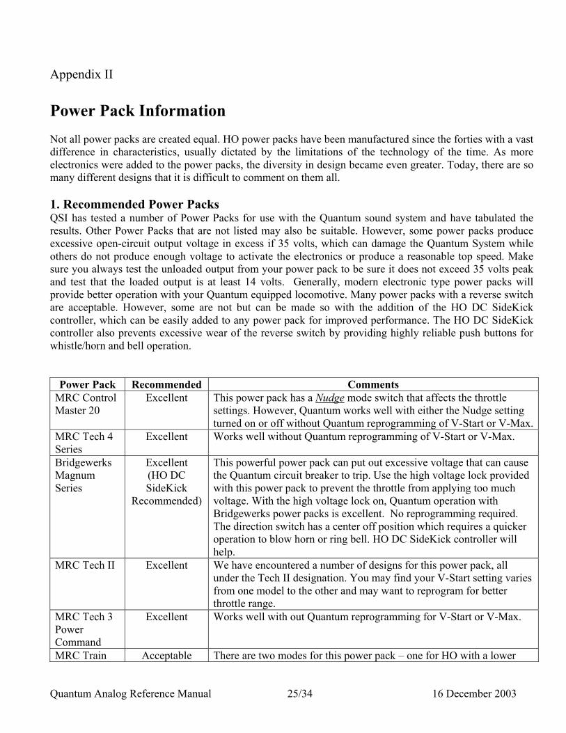
Appendix II Power Pack Information Not all power packs are created equal. HO power packs have been manufactured since the forties with a vast difference in characteristics, usually dictated by the limitations of the technology of the time. As more electronics were added to the power packs, the diversity in design became even greater. Today, there are so many different designs that it is difficult to comment on them all. 1. Recommended Power Packs QSI has tested a number of Power Packs for use with the Quantum sound system and have tabulated the results. Other Power Packs that are not listed may also be suitable. However, some power packs produce excessive open-circuit output voltage in excess if 35 volts, which can damage the Quantum System while others do not produce enough voltage to activate the electronics or produce a reasonable top speed. Make sure you always test the unloaded output from your power pack to be sure it does not exceed 35 volts peak and test that the loaded output is at least 14 volts. Generally, modern electronic type power packs will provide better operation with your Quantum equipped locomotive. Many power packs with a reverse switch are acceptable. However, some are not but can be made so with the addition of the HO DC SideKick controller, which can be easily added to any power pack for improved performance. The HO DC SideKick controller also prevents excessive wear of the reverse switch by providing highly reliable push buttons for whistle/horn and bell operation.
Power Pack Recommended Comments MRC Control Master 20
Excellent This power pack has a Nudge mode switch that affects the throttle settings. However, Quantum works well with either the Nudge setting turned on or off without Quantum reprogramming of V-Start or V-Max.
MRC Tech 4 Series
Excellent Works well without Quantum reprogramming of V-Start or V-Max.
Bridgewerks Magnum Series
Excellent (HO DC SideKick
Recommended)
This powerful power pack can put out excessive voltage that can cause the Quantum circuit breaker to trip. Use the high voltage lock provided with this power pack to prevent the throttle from applying too much voltage. With the high voltage lock on, Quantum operation with Bridgewerks power packs is excellent. No reprogramming required. The direction switch has a center off position which requires a quicker operation to blow horn or ring bell. HO DC SideKick controller will help.
MRC Tech II Excellent We have encountered a number of designs for this power pack, all under the Tech II designation. You may find your V-Start setting varies from one model to the other and may want to reprogram for better throttle range.
MRC Tech 3 Power Command
Excellent Works well with out Quantum reprogramming for V-Start or V-Max.
MRC Train Acceptable There are two modes for this power pack – one for HO with a lower
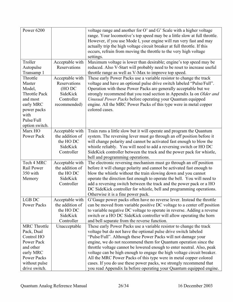
Quantum Analog Reference Manual 26/34 16 December 2003
Power 6200
voltage range and another for O’ and G’ Scale with a higher voltage range. Your locomotive’s top speed may be a little slow at full throttle. However, if you use Mode I, your engine will run very fast and may actually trip the high voltage circuit breaker at full throttle. If this occurs, refrain from moving the throttle to the very high voltage settings.
Troller Autopulse Transamp 1
Acceptable with Reservations
Maximum voltage is lower than desirable; engine’s top speed may be reduced. Also V-Start will probably need to be reset to increase useful throttle range as well as V-Max to improve top speed.
Throttle Master Model, Throttle Pack and most early MRC power packs with Pulse/Full option switch.
Acceptable with Reservations
(HO DC SideKick Controller
recommended)
These early Power Packs use a variable resistor to change the track voltage and have an optional pulse drive switch labeled “Pulse/Full”. Operation with these Power Packs are generally acceptable but we strongly recommend that you read section in Appendix Ia on Older and Unusual Power Packs before operating your Quantum equipped engine. All the MRC Power Packs of this type were in metal copper colored cases.
Marx HO Power Pack
Acceptable with the addition of
the HO DC SideKick Controller
Train runs a little slow but it will operate and program the Quantum system. The reversing lever must go through an off position before it will change polarity and cannot be activated fast enough to blow the whistle reliably. You will need to add a reversing switch or HO DC SideKick controller between the track and the power pack for whistle, bell and programming operations.
Tech 4 MRC Rail Power 350 with Memory
Acceptable with the addition of
the HO DC SideKick Controller
The electronic reversing mechanism must go through an off position before it will change polarity and cannot be activated fast enough to blow the whistle without the train slowing down and you cannot operate the direction fast enough to operate the bell. You will need to add a reversing switch between the track and the power pack or a HO DC SideKick controller for whistle, bell and programming operations. Otherwise it is a fine power pack.
LGB DC Power Packs
Acceptable with the addition of
the HO DC SideKick Controller
G’Gauge power packs often have no reverse lever. Instead the throttle can be moved from variable positive DC voltage to a center off position to variable negative DC voltage to operate in reverse. Adding a reverse switch or a HO DC SideKick controller will allow operating the horn and bell separate from the reverse function.
MRC Throttle Pack, Dual Control HO Power Pack and other early MRC Power Packs without pulse drive switch.
Unacceptable These early Power Packs use a variable resistor to change the track voltage but do not have the optional pulse drive switch labeled “Pulse/Full”. Although these Power Packs will not damage your engine, we do not recommend them for Quantum operation since the throttle voltage cannot be lowered enough to enter neutral. Also, peak voltage can be high enough to engage the high voltage circuit breaker. All the MRC Power Packs of this type were in metal copper colored cases. If you do use these power packs, we strongly recommend that you read Appendix Ia before operating your Quantum equipped engine.
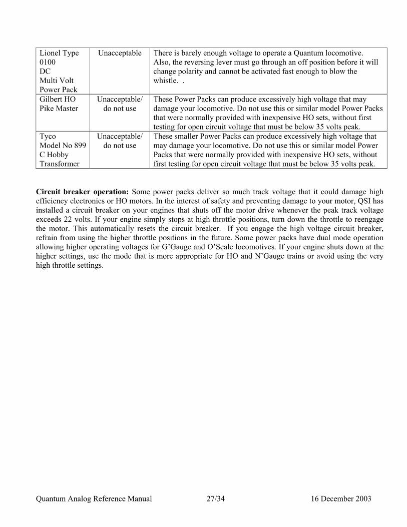
Quantum Analog Reference Manual 27/34 16 December 2003
Lionel Type 0100 DC Multi Volt Power Pack
Unacceptable There is barely enough voltage to operate a Quantum locomotive. Also, the reversing lever must go through an off position before it will change polarity and cannot be activated fast enough to blow the whistle. .
Gilbert HO Pike Master
Unacceptable/ do not use
These Power Packs can produce excessively high voltage that may damage your locomotive. Do not use this or similar model Power Packs that were normally provided with inexpensive HO sets, without first testing for open circuit voltage that must be below 35 volts peak.
Tyco Model No 899 C Hobby Transformer
Unacceptable/ do not use
These smaller Power Packs can produce excessively high voltage that may damage your locomotive. Do not use this or similar model Power Packs that were normally provided with inexpensive HO sets, without first testing for open circuit voltage that must be below 35 volts peak.
Circuit breaker operation: Some power packs deliver so much track voltage that it could damage high efficiency electronics or HO motors. In the interest of safety and preventing damage to your motor, QSI has installed a circuit breaker on your engines that shuts off the motor drive whenever the peak track voltage exceeds 22 volts. If your engine simply stops at high throttle positions, turn down the throttle to reengage the motor. This automatically resets the circuit breaker. If you engage the high voltage circuit breaker, refrain from using the higher throttle positions in the future. Some power packs have dual mode operation allowing higher operating voltages for G’Gauge and O’Scale locomotives. If your engine shuts down at the higher settings, use the mode that is more appropriate for HO and N’Gauge trains or avoid using the very high throttle settings.
Quantum Analog Reference Manual 28/34 16 December 2003
Appendix IIa Hints For Use With Older and Unusual Power Packs 1. Programming your Quantum Locomotive with Older Power Packs Equipped with a Pulse Drive Switch
1.1 Using older power packs: Older non-electronic power packs often use a variable high power resistor to change the track voltage, which usually requires a load on the track to operate properly. Since Quantum engines take less power as it slows down, your older Power Packs may not allow the locomotive to operate under pulse drive and the direction switch may not produce the correct whistle or bell operations. We suggest you add a SideKick DC Controller and a fixed load to the variable DC output on your power pack. We have found that a 500-ohm, 1 watt resistor will improve performance. Note that this resistor can become hot so place it where it will not be touched by hand and away from flammable material. If your power pack has a pulse drive switch, set the position to full power for all your normal engine operations. Pulse drive has no advantage for operating your Quantum locomotive since it usually produces low voltage along with the pulse operation and will not provide enough voltage to leave neutral. While in full power, check to see that your engine will slow down enough to enter neutral. If not, your will need to enter programming to reset the throttle position to allow the engine to slow down to a full stop. 1.2 Programming: Programming should not be a problem. If you cannot turn the throttle down low enough to stop the engine, you can still enter programming even if the engine is moving. The engine will stop once programming is entered. 1.3 Entering Neutral: You can also enter neutral using the pulse mode switch. Although you may not be able to enter neutral using the Full power mode, you can bring your engine to a slow speed. Flipping the Pulse/Full switch to Pulse will allow the engine to stop in neutral. You can also try resetting your V-Start value in the programming mode although this does not always work with every older power pack: To do this. 1. Enter Programming. 2. Go to Option 8 and enter the option. 3. Flip the Pulse/Full switch to Full and move the throttle to the position where you want
the engine to leave neutral (about 20% of full throttle). The voltage verbal voltage reading from the engine should not be less than five volts.
4. Use the reverse lever to begin the V-Start procedure. The bell will start ringing continually, indicating the process is calculating the correct value of throttle setting.
5. At the end of the process, the engine will move slightly and stop. The whistle will hoot, signifying the end of the operation. You will hear “V-Start equals X” where X is the
Quantum Analog Reference Manual 29/34 16 December 2003
new V-Start voltage setting. If this setting is not greater than 5 volts, you will need to enter the option again and set your throttle higher.
6. To leave programming, interrupt the power by turning the throttle off, and then power up for usual engine operation with the Pulse/Full switch in the Full position.
Note: If you are still unable to enter neutral, you may find that the factory settings are the best choice. Reprogram your engine in option 8 to factory default values. 1.4 High-Voltage Circuit Breaker: Some of these older Power Packs have excessively high open-circuit output voltage that can trigger the high voltage circuit breaker in your locomotive. The high voltage will not damage your engine but can prevent it from moving. Normally, the motors in typical non-sound equipped HO engines will load this type of power pack and draw down the voltage. However, Quantum equipped engines provide a very low load when the motors are not engaged (i.e. in neutral and programming mode) which may allow the Power Pack voltage to float to a high enough value to trigger the circuit breaker. Try turning the throttle up very slowly from its minimum position to allow the motors to engage at the lowest possible value. Once the motors are engaged, the voltage will usually be kept low enough value to prevent the circuit breaker from activating over most of throttle range.
Quantum Analog Reference Manual 30/34 16 December 2003
Appendix III Troubleshooting: Engine coasts to a stop at full throttle setting and just emits a series of hoots.
Circuit breaker has been tripped from too much voltage applied to the track. Turn the throttle down a little to re-engage the motors. Refrain from using these higher throttle settings.
Bell will not toggle on and off. Make sure you are not flipping the direction switch back and forth too quickly or too slowly. A little practice with your timing will give you a feel for how this operation works. It also helps to use your other hand to steady the power pack to keep it from slipping during the Quick flip-and-back operation.
Engine does not make any sounds but responds to throttle.
Make sure the system volume or individual volumes are not turned off. If you do not hear verbal commands in programming, your speaker may be disconnected or wires may be disconnected from the speaker terminals.
When blowing the whistle, the engine stutters slightly before the whistle goes on.
You are moving the direction switch too slowly through its center position. In that position, the power to the track is momentarily turned off.
I want to change directions in neutral but flipping the direction switch makes the whistle come on.
You need to change the direction switch before the second air release and the pumps come on. If you waited too long and the whistle comes on when you flip the direction switch, simple turn up the throttle: the engine will start in the opposite direction and the whistle will stop.
I cannot get the whistle to blow or the bell to toggle in neutral using the direction switch.
After entering neutral, wait for the second air release and the start of the air pumps before trying to use the direction switch to operate the whistle or bell.
The engine will not enter neutral. If the engine comes to a complete stop and there is enough track voltage to keep the sounds on, it will enter neutral. If you cannot get your engine to stop with power still applied, you may need to set a new “V-Start”. If you cannot use your current power pack to do this, use another power pack from the recommended list and set “V-Start” until it does work with your power pack.
The engine will not produce the doppler shift effect. This might be a timing problem. Always blow the whistle/horn for at least 1 second before interrupting the whistle/horn signal with a quick flip-and-back operation of the direction switch. If you flip it too slowly, the whistle/horn will actually shut off and turn back on again. Also, doppler is speed dependent
Quantum Analog Reference Manual 31/34 16 December 2003
and does not play below 15 smph. Sounds come on but I cannot get my engine to move when I increase the throttle.
Your Power Pack may not have sufficient maximum throttle voltage. If it measures below about 11 volts with a voltmeter, it may not have enough power to operate your engine. We recommend power packs with a maximum throttle output of 14 volts. On the other hand, some power packs have too much open circuit (unloaded) voltage when turned on even at the lowest throttle position. This will activate the high voltage circuit breaker on the locomotive and prevent the motors from engaging. Try turning the throttle up very slowly when leaving neutral to allow the motors to engage at the lowest possible track voltage. Often times, when the motors do engage, they will load the power pack enough to prevent the circuit breaker from engaging even at the highest setting.
I cannot get my engine to enter neutral by lowering the throttle.
You may need to reset the V-start value for operation with your power pack. If you have an older power pack, read the power pack descriptions in Appendix 1a.
When using 12 volts filtered DC on the track, my top speed is too slow at full throttle.
Quantum is designed to operate with the most popular power packs that usually have a maximum voltage of 16 volts. Set V-max to about 10 volts for your 12-volt power pack for much higher top speed.
When I enter a high inertia and turn up my throttle all the way to start out, the engine does not move and emits a series of short hoots. However, without inertia, it operates fine at high throttle.
When operating without inertia, the engine requires full current as the throttle is turned up which lowers the output voltage because of internal resistance in most power packs. However, when inertia is set high, and the throttle turned up all the way, there is at first very little current demand from the engine and the power pack produces maximum voltage, which cause the circuit breaker to engage. When operating with high inertia, turn up the throttle part way until the engine gets moving before turning it up to full.
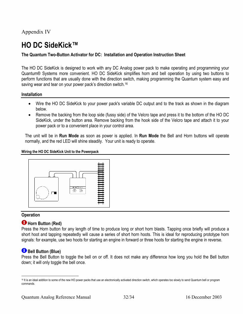
Quantum Analog Reference Manual 32/34 16 December 2003
Appendix IV
HO DC SideKick™ The Quantum Two-Button Activator for DC: Installation and Operation Instruction Sheet The HO DC SideKick is designed to work with any DC Analog power pack to make operating and programming your Quantum® Systems more convenient. HO DC SideKick simplifies horn and bell operation by using two buttons to perform functions that are usually done with the direction switch, making programming the Quantum system easy and saving wear and tear on your power pack’s direction switch.16 Installation
• Wire the HO DC SideKick to your power pack's variable DC output and to the track as shown in the diagram below.
• Remove the backing from the loop side (fussy side) of the Velcro tape and press it to the bottom of the HO DC SideKick, under the button area. Remove backing from the hook side of the Velcro tape and attach it to your power pack or to a convenient place in your control area.
The unit will be in Run Mode as soon as power is applied. In Run Mode the Bell and Horn buttons will operate normally, and the red LED will shine steadily. Your unit is ready to operate.
Wiring the HO DC SideKick Unit to the Powerpack
Operation
Horn Button (Red) Press the Horn button for any length of time to produce long or short horn blasts. Tapping once briefly will produce a short hoot and tapping repeatedly will cause a series of short horn hoots. This is ideal for reproducing prototype horn signals: for example, use two hoots for starting an engine in forward or three hoots for starting the engine in reverse.
Bell Button (Blue) Press the Bell Button to toggle the bell on or off. It does not make any difference how long you hold the Bell button down; it will only toggle the bell once. 16 It is an ideal addition to some of the new HO power packs that use an electronically activated direction switch, which operates too slowly to send Quantum bell or program commands.
Quantum Analog Reference Manual 33/34 16 December 2003
Note: Tapping the horn and bell will be remembered by the HO DC SideKick for up to eleven operations. You can use this memory feature to hoot the horn and toggle the bell on and off in succession according to the sequence you have entered.
Combination Horn and Bell Button Operation
Doppler Effect • Blow the horn with the Horn button and interrupt the horn signal briefly by releasing and re-pressing the Horn
button, • OR operate the Doppler effect by continuing to hold the horn button down and tap the Bell button once while
the Horn button is still pressed 17.
The Power Pack Direction Switch
Use the direction switch to change the direction of your engine as described in the Quantum Operation manual supplied with your locomotive. Quantum Programming
To enter Programming Mode: • Hold either the Bell or Horn button down while you turn on track power to trigger the HO DC SideKick to enter
Programming Mode18. • The Red LED on the HO DC SideKick and the directional lights on the locomotive will blink to indicate that you
are in Programming Mode and you will hear "Enter Programming. Option 1 – System Volume".
Selecting the Program Option
• Hold the Horn button down until the Quantum System starts counting through the Program Option numbers one by one. It will count from Option 1 up through the last option available for your locomotive and then will start again at Option 1 and repeat the cycle.
• When you reach the number for the Program Option you want, release the Horn Button. The Quantum System will announce the Option Name. For example, if you stopped at option number 14, you would hear "Bell Volume".
• If you missed your option number or want to move on to other options, either: 1) press and hold the Horn button or 2) turn off the power and re-enter programming as described above.
Note: If you press the horn button when you first apply power, and continue pressing the horn button, the HO DC SideKick will automatically enter programming and count up through the Program Options. Release the Horn button when you reach the desired Program Option. Note: Pressing the Bell button will not decrease the program option level you are at, it will enter the option. You can only scroll forward with the Horn button to select program options.
17 There is no effect designated for holding the bell down and tapping the horn button. This procedure will simply toggle the bell feature. 18 You can enter programming by tapping the bell button three times in rapid succession after you apply power, just as described in your Quantum Operating manual. However, the HO DC SideKick horn timing is different in Programming than in Run Mode. You will need to hold the horn button down until your hear the soft hiss from the Quantum system as described in order to increase the level setting.
Quantum Analog Reference Manual 34/34 16 December 2003
Use Horn or Bell Button to Enter and Change the Programming Option
After you stop at the Program Option you want, tapping the Horn or Bell button will enter the option. You will hear the current value for that programming option spoken out from the Quantum system in the locomotive. The next time you press either button, you will be making changes to the value for that option.
Horn (Red) Pressing the Horn button will increase the level of the option's value each time it is tapped. If it is quickly tapped repeatedly, the HO DC SideKick will remember the number of times it was pressed and you will hear the Quantum system progress to the next option level for each of the stored button pressings. • Hold down the Horn button to leave the current program option and start advancing through the next
programming options.
Bell (Blue) Pressing the Bell button will decrease the level of the option's value each time it is tapped. If it is quickly tapped repeatedly, the HO DC SideKick will remember the number of times it was pressed and you will hear the Quantum system count down to the next option level for each of the stored button pressings. • Hold down the Horn button to leave the current program option and start advancing through the programming
options.
Leaving Programming
• To leave programming, simply turn the power off and back on. The DC SideKick’s LED and the Quantum engine’s directional lighting will stop blinking and both will begin to shine steadily.
• You are now in Run Mode and ready to Operate. The HO DC SideKick Hardware, Software and Firmware are covered by one or more of the following patents: U.S. Patent No. 4,914,431; 5,184,048; 5,267,318; 5,394,068; 5,448,142; 5,633,985; 5,832,431; 5,896,017; 5,940,005. © 2003 QSIndustries, Inc. All rights reserved. Printed in the U.S.A. Information in this publication supersedes that in all previous published material. The contents and the product it describes are subject to change without notice. QSI is a registered trademark of QSIndustries, Inc. Quantum and SideKick are trademarks of QSIndustries, Inc. QSI makes no representations or warranties with respect to this publication. In no event shall QSIndustries, Inc., be liable for any damages, direct or incidental, arising out of or related to the use of this publication. 8/03.
QSIndustries, Inc. Software License Agreement 1. Grant of License: QSIndustries, Inc. grants you, the owner, the right to use the software that is included with your Quantum system only with the locomotive that you purchased. 2. Copyright: The software is owned by QSIndustries, Inc. and is protected by United States copyright laws and international treaty provisions. Therefore, neither you nor anyone else may copy the software. Proprietary Rights and Obligations The structure and organization of the Software/Firmware are the valuable properties of QSIndustries, Inc. You will not make or have made, or permit to be made, any copies of the Hardware, Software/Firmware, code, or any portions thereof. You are not to modify, adapt, translate, reverse engineer, de-compile, disassemble or create derivative works based on the Hardware or Software/Firmware. Trademarks shall be used in accordance with accepted trademark practice, including identification of trademark owner’s name. The Quantum Hardware, Software and Firmware are covered by U.S. Patent No. 4,914,431; 5,184,048; 5,267,318; 5,394,068; 5,448,142; 5,633,985; 5,832,431; 5,896,017; 5,940,005; Foreign patents pending. No Other Rights QSIndustries, Inc. retains ownership of the Quantum Hardware design and operating Software/Firmware code. Except as stated above, this agreement does not grant you any rights to intellectual property rights to the Quantum Software, Firmware or Hardware. The use of any trademarks as herein authorized does not give you any rights of ownership in that trademark. © 2003. All rights reserved. Printed in the U.S.A. Information in this publication supersedes that in all previous published material. The contents and the product it describes are subject to change without notice. Lionel is a trademark of Lionel LLC. QSI is a registered trademark of QSIndustries, Inc. Quantum, Quantum Sound, Sound-of-Power, Scale Sound and Regulated Throttle are trademarks of QSIndustries, Inc. All other trademarks are the property of their respective holders. QSI makes no representations or warranties with respect to this publication. In no event shall QSIndustries, Inc., be liable for any damages, direct or incidental, arising out of or related to the use of this publication. 6/03
QSIndustries, Inc. Beaverton, OR