quantum mechanics in electronics
TRANSCRIPT
QUANTUM MECHANICS IN
ELECTRONICS
Amit Kumar Mohapatra
14MSL005
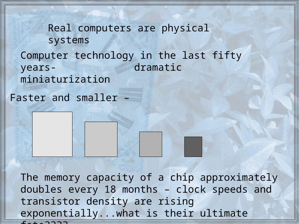
The memory capacity of a chip approximately doubles every 18 months – clock speeds and transistor density are rising exponentially...what is their ultimate fate????
Real computers are physical systems
Computer technology in the last fifty years- dramatic miniaturization
Faster and smaller –
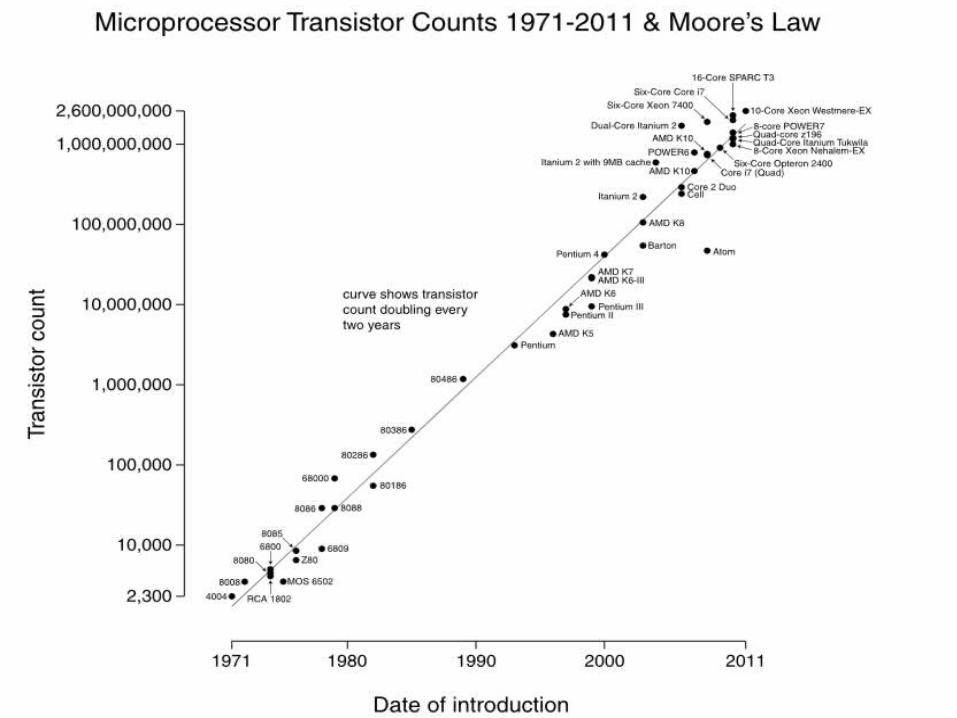
Moore’s law
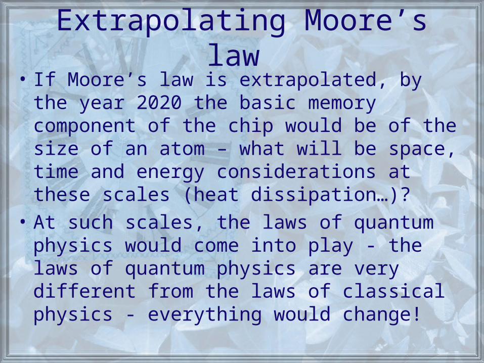
Extrapolating Moore’s law • If Moore’s law is extrapolated, by the year
2020 the basic memory component of the chip would be of the size of an atom – what will be space, time and energy considerations at these scales (heat dissipation…)?
• At such scales, the laws of quantum physics would come into play - the laws of quantum physics are very different from the laws of classical physics - everything would change!
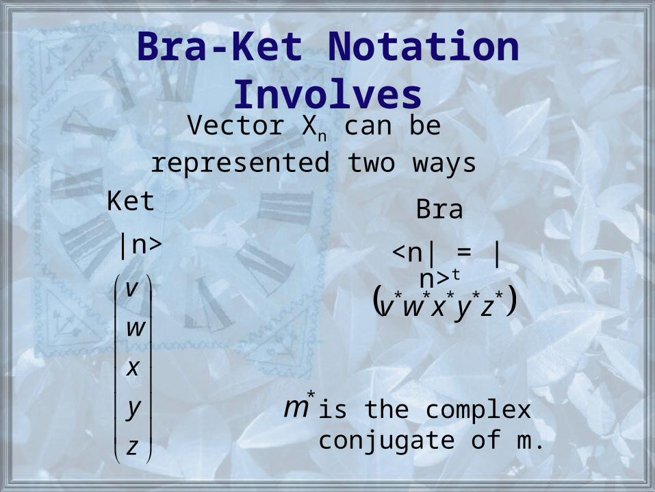
Bra-Ket Notation InvolvesVector Xn can be represented two
ways
Ket
|n>
z
y
x
w
v
Bra
<n| = |n>t
***** zyxwv
*m is the complex conjugate of m.
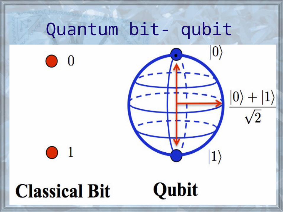
Quantum bit- qubit
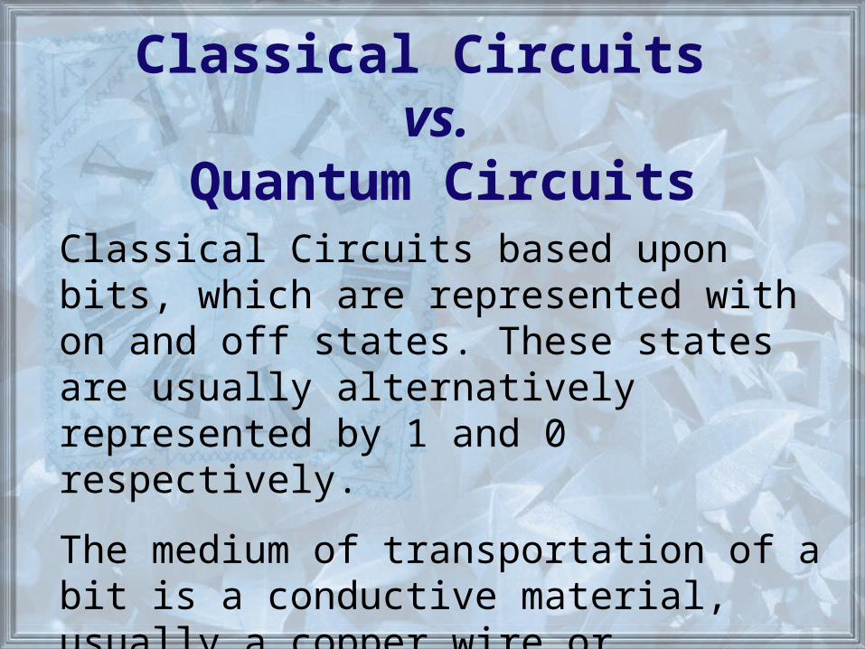
Classical Circuits vs.
Quantum CircuitsClassical Circuits based upon bits, which are represented with on and off states. These states are usually alternatively represented by 1 and 0 respectively.
The medium of transportation of a bit is a conductive material, usually a copper wire or something similar. The 1 or 0 is represented with 2 different levels of current through the wire.
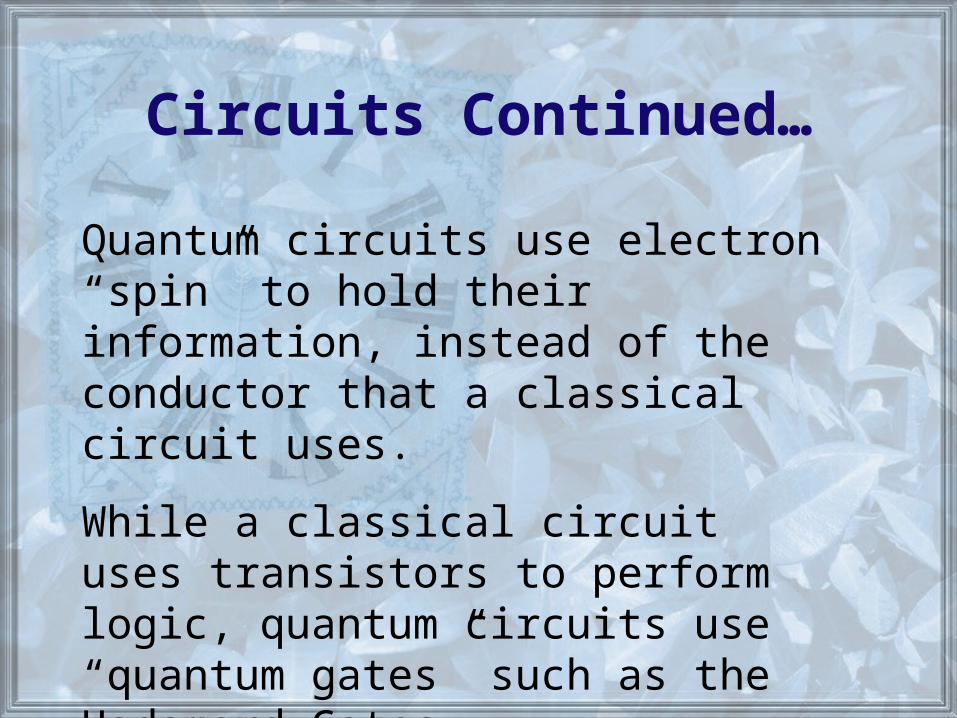
Circuits Continued…
Quantum circuits use electron “spin” to hold their information, instead of the conductor that a classical circuit uses.
While a classical circuit uses transistors to perform logic, quantum circuits use “quantum gates” such as the Hadamard Gates.
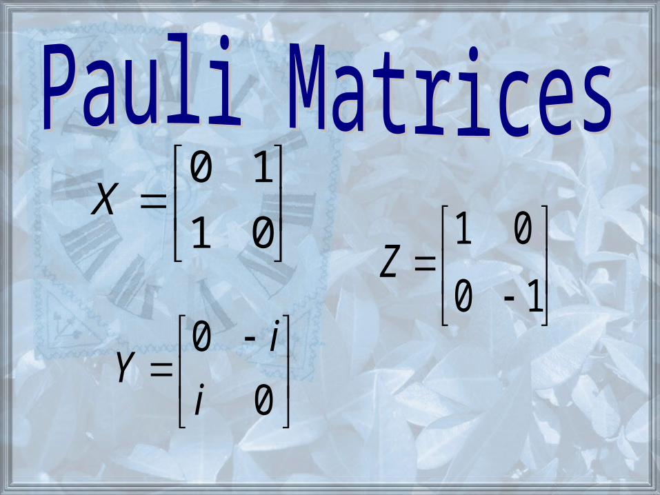
01
10X
0
0
i
iY
10
01Z
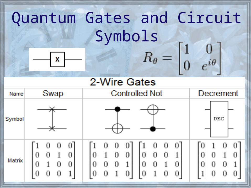
Quantum Gates and Circuit Symbols
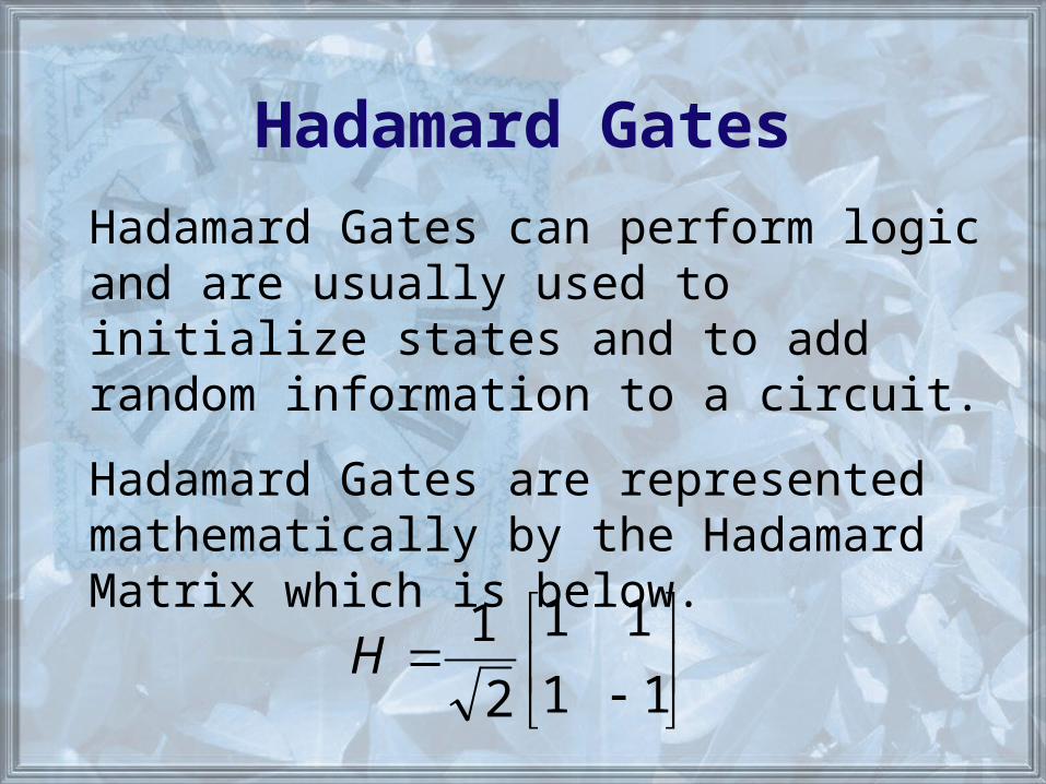
Hadamard Gates
Hadamard Gates can perform logic and are usually used to initialize states and to add random information to a circuit.
Hadamard Gates are represented mathematically by the Hadamard Matrix which is below.
11
11
2
1H
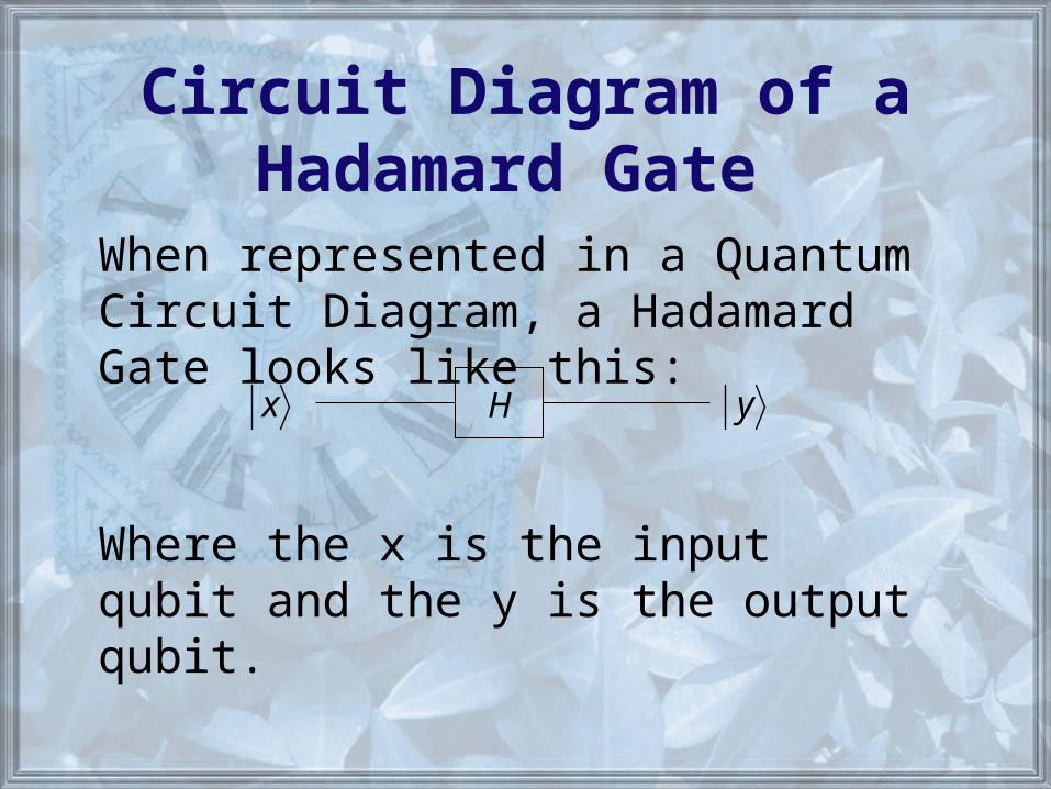
Circuit Diagram of aHadamard Gate
Hx y
When represented in a Quantum Circuit Diagram, a Hadamard Gate looks like this:
Where the x is the input qubit and the y is the output qubit.
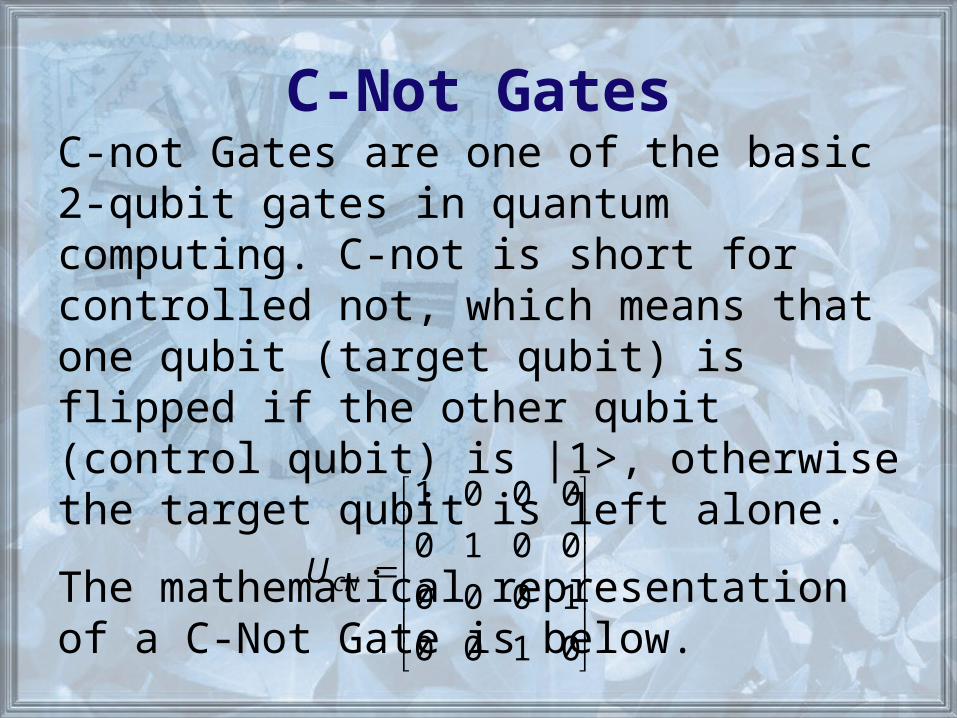
C-Not GatesC-not Gates are one of the basic 2-qubit gates in quantum computing. C-not is short for controlled not, which means that one qubit (target qubit) is flipped if the other qubit (control qubit) is |1>, otherwise the target qubit is left alone.
The mathematical representation of a C-Not Gate is below.
0100
1000
0010
0001
CNU
Circuit Diagram of a C-Not Gate
x
y
x
yx
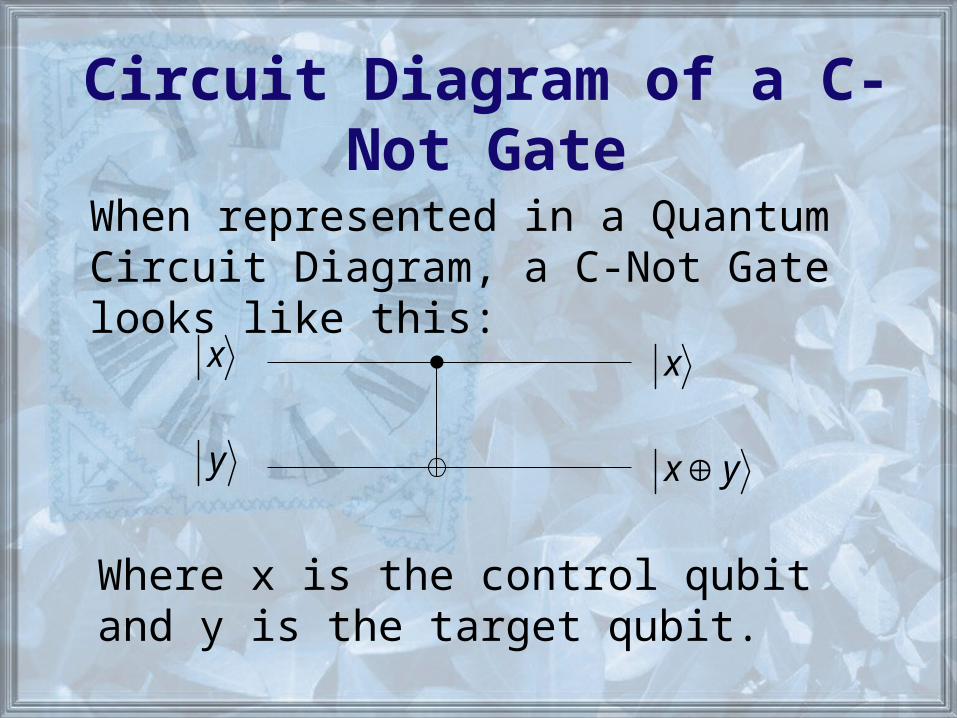
When represented in a Quantum Circuit Diagram, a C-Not Gate looks like this:
Where x is the control qubit and y is the target qubit.
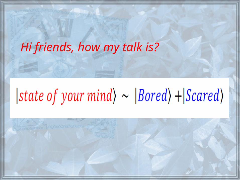
Hi friends, how my talk is?