quartus ii laboratory exercise manual for introduction to vhdlintroduction to vhdl lab overview...
TRANSCRIPT
Quartus II Laboratory Exercise Manual
for Introduction to VHDL

Exercises Introduction to VHDL
Copyright © 2000 Altera Corporation
2

Introduction to VHDL Exercises
Copyright © 2000 Altera Corporation 3
Introduction to VHDL Lab Overview
Objective : Build a sequential 8 X 8 multiplier The objective of the following exercises is to build an 8 X 8 multiplier. The input to the multiplier consists of two 8-bit multiplicands (a[7..0], b[7..0]) and the output from the multiplier is a 16-bit result (result[15..0]). Additional outputs are a done bit (DONE_FLAG) and seven signals to drive a seven segment display, (A, B, C, D, E, F, G). There are several methods of implementing a multiplier; the method chosen for the VHDL labs is the sequential multiplier method. This 8 X 8 multiplier requires four clock cycles to perform the full multiplication. During each cycle, a pair of 4-bit portion of the multiplicands are multiplied in a 4 X 4 multiplier. The multiplication result of these 4 bit slices is then accumulated. At the end of the four cycles, the fully composed 16-bit result can be read at the output. The following equations illustrate the mathematical principles supporting this implementation: result[15..0] = a[7..0] * b[7..0] = ( ( a[7..4] * 2 ^ 4) + a[3..0] * 2 ^ 0 ) * ( ( b[7..4] * 2 ^ 4) + b[3..0] * 2 ^ 0 ) = ( ( a[7..4] * b[7..4] ) * 2 ^ 8 ) + ( ( a[7..4] * b[3..0] ) * 2 ^ 4 ) + ( ( a[3..0] * b[7..4] ) * 2 ^ 4 ) + ( ( a[3..0] * b[3..0] ) * 2 ^ 0 ) Figure 1 in the following page illustrates the top-level block diagram of the 8 X 8 multiplier. The labs are structured as a bottom-up design approach. In each of the first five exercises, you will use targeted features of the VHDL language to build the individual components of the 8 X 8 multiplier. Then, in exercise 6 you will put everything together in a top-level design. You will then compile and simulate to verify the completeness of your design. Good luck and have fun going through the exercises!

Exercises Introduction to VHDL
Copyright © 2000 Altera Corporation
4
Figure 1 - 8 X 8 multiplier top level design block diagram

Introduction to VHDL Exercises
Copyright © 2000 Altera Corporation 5
Exercise 1
Exercises Introduction to VHDL
Copyright © 2000 Altera Corporation
6
Exercise 1
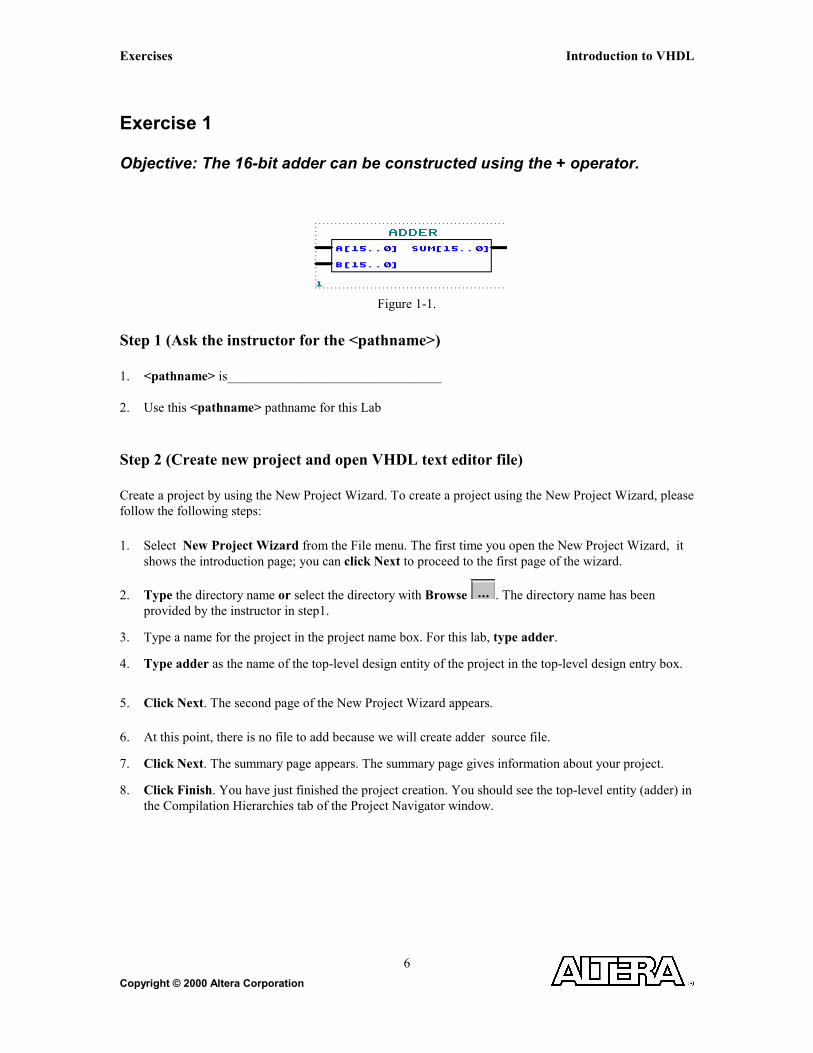
Objective: The 16-bit adder can be constructed using the + operator.
Figure 1-1.
Step 1 (Ask the instructor for the <pathname>) 1. <pathname> is________________________________ 2. Use this <pathname> pathname for this Lab Step 2 (Create new project and open VHDL text editor file) Create a project by using the New Project Wizard. To create a project using the New Project Wizard, please follow the following steps:
1. Select New Project Wizard from the File menu. The first time you open the New Project Wizard, it shows the introduction page; you can click Next to proceed to the first page of the wizard.
2. Type the directory name or select the directory with Browse . The directory name has been provided by the instructor in step1.
3. Type a name for the project in the project name box. For this lab, type adder.
4. Type adder as the name of the top-level design entity of the project in the top-level design entry box.
5. Click Next. The second page of the New Project Wizard appears.
6. At this point, there is no file to add because we will create adder source file.
7. Click Next. The summary page appears. The summary page gives information about your project.
8. Click Finish. You have just finished the project creation. You should see the top-level entity (adder) in the Compilation Hierarchies tab of the Project Navigator window.

Introduction to VHDL Exercises
Copyright © 2000 Altera Corporation 7
9. From the File menu select new or click on . New file dialog box will appear and select VHDL
file. Click on OK
Figure 1-2.
10. VHDL text editor will appear.
11. Before the beginning of your code (before the ENTITY), type the following:
LIBRARY ieee;
USE ieee.std_logic_1164.all;
USE ieee.std_logic_unsigned.all;
12. Write your source code.
Remember to use the same input and output port names as shown in Figure 1-1. 13. Go to File menu and Choose Save As.
Save new VHDL text file to <path>\altera_trn\vhdl\lab1\adder.vhd.

Exercises Introduction to VHDL
Copyright © 2000 Altera Corporation
8
Step 3 (Save and check design)
Click on Start Analysis & Elaboration .
This will save and check for syntax and semantic errors for the file adder.vhd. When you see the message
“Analysis and elaboration was successful”, click OK.
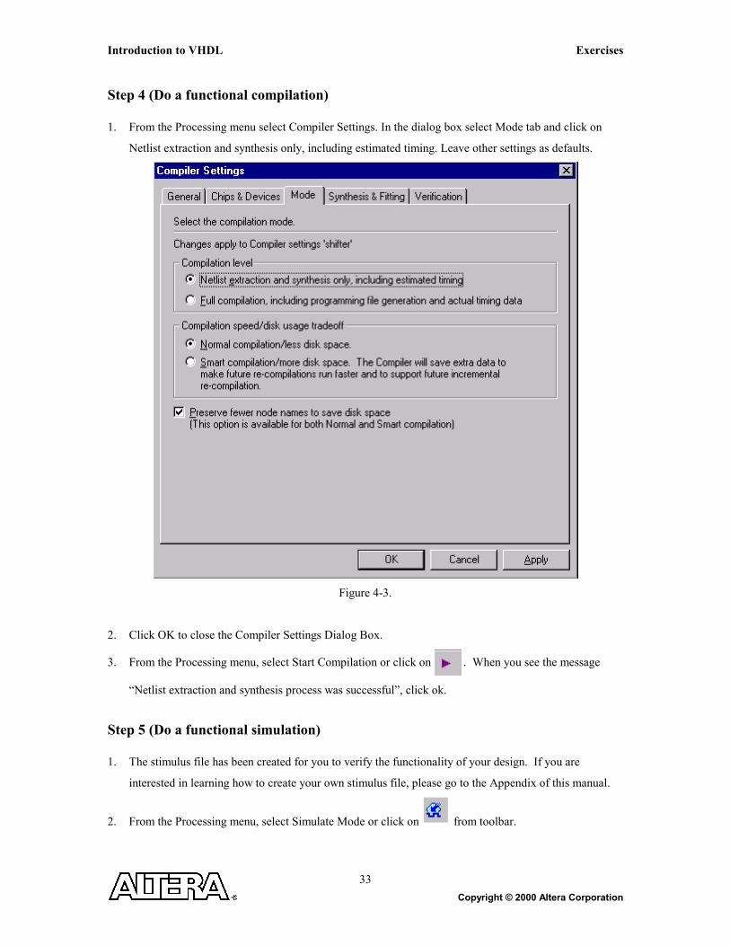
Step 4 (Do a functional compilation) 1. From the Processing menu select Compiler Settings. In the dialog box select Mode tab and click on
Netlist extraction and synthesis only, including estimated timing. Leave other settings as defaults.
Figure 1-3.
2. Click OK to close the Compiler Settings Dialog Box.
3. From the Processing menu, select Start Compilation or click on . When you see the message
“Netlist extraction and synthesis process was successful”, click OK.

Introduction to VHDL Exercises
Copyright © 2000 Altera Corporation 9
Step 5 (Do a functional simulation) 1. The stimulus file has been created for you to verify the functionality of your design. If you are
interested in learning how to create your own stimulus file, please go to the Appendix of this manual.
2. From the Processing menu, select Simulate Mode or click on from toolbar.
3. From the Processing menu, select Simulator Settings. Once the Simulator Settings Dialog Box appears,
click on Time/Vectors tab to browse to the vector stimuli file (Adder.tbl which is given to you.).
To browse to the adder.tbl file Click on . <path>\altera_trn\vhdl\lab1\adder.tbl .
Note: Remember to change Files of type field to All files (*.*) and Select adder.tbl.
Figure 1-4.

Exercises Introduction to VHDL
Copyright © 2000 Altera Corporation
10
4. Click on Apply.
5. In the Simulator Settings Dialog Box, click on the Mode tab. Change the simulation mode to be
Functional. Click OK to close the Simulator Settings Dialog Box.
Figure 1-5.
6. From the Processing menu select Run Simulation or click on . When you see the message,
“Simulation was successful”, click OK.
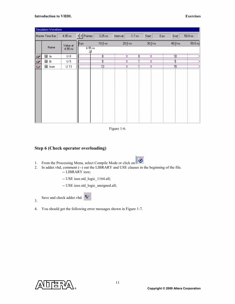
7. Check to see if you get the same results shown in Figure 1-6.
Introduction to VHDL Exercises
Copyright © 2000 Altera Corporation 11
Figure 1-6.
Step 6 (Check operator overloading)
1. From the Processing Menu, select Compile Mode or click on 2. In adder.vhd, comment (--) out the LIBRARY and USE clauses in the beginning of the file.
-- LIBRARY ieee;
-- USE ieee.std_logic_1164.all;
-- USE ieee.std_logic_unsigned.all;
3. Save and check adder.vhd.
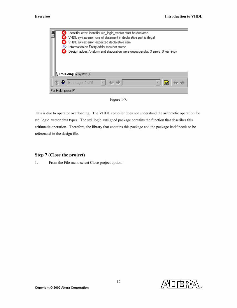
4. You should get the following error messages shown in Figure 1-7.
Exercises Introduction to VHDL
Copyright © 2000 Altera Corporation
12
Figure 1-7.
This is due to operator overloading. The VHDL compiler does not understand the arithmetic operation for
std_logic_vector data types. The std_logic_unsigned package contains the function that describes this
arithmetic operation. Therefore, the library that contains this package and the package itself needs to be
referenced in the design file.
Step 7 (Close the project)
1. From the File menu select Close project option.

Introduction to VHDL Exercises
Copyright © 2000 Altera Corporation 13
Exercise 2
Exercises Introduction to VHDL
Copyright © 2000 Altera Corporation
14
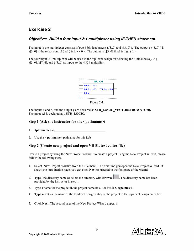
Exercise 2
Objective: Build a four input 2:1 multiplexer using IF-THEN statement. The input to the multiplexer consists of two 4-bit data buses ( a[3..0] and b[3..0] ). The output ( y[3..0] ) is a[3..0] if the select control ( sel ) is low ( 0 ). The output is b[3..0] if sel is high ( 1 ). The four input 2:1 multiplexer will be used in the top level design for selecting the 4-bit slices a[7..4], a[3..0], b[7..4], and b[3..0] as inputs to the 4 X 4 multiplier.
Figure 2-1.
The inputs a and b, and the output y are declared as STD_LOGIC_VECTOR(3 DOWNTO 0). The input sel is declared as a STD_LOGIC. Step 1 (Ask the instructor for the <pathname>) 1. <pathname> is________________________________ 2. Use this <pathname> pathname for this Lab Step 2 (Create new project and open VHDL text editor file) Create a project by using the New Project Wizard. To create a project using the New Project Wizard, please follow the following steps:
1. Select New Project Wizard from the File menu. The first time you open the New Project Wizard, it shows the introduction page; you can click Next to proceed to the first page of the wizard.
2. Type the directory name or select the directory with Browse . The directory name has been provided by the instructor in step1.
3. Type a name for the project in the project name box. For this lab, type mux4.
4. Type mux4 as the name of the top-level design entity of the project in the top-level design entry box.
5. Click Next. The second page of the New Project Wizard appears.

Introduction to VHDL Exercises
Copyright © 2000 Altera Corporation 15
6. At this point, there is no file to add because we will create mux4 source file.
7. Click Next. The summary page appears. The summary page gives information about your project
8. Click Finish. You have just finished the project creation. You should see the top-level entity (mux4) in the Compilation Hierarchies tab of the Project Navigator window.
9. From the File menu select new or click on . New file dialog box will appear and select VHDL
file. Click OK.
Figure 2-2.
10. VHDL text editor will appear.
11. Before the beginning of your code (before the ENTITY), type the following:
LIBRARY ieee;
USE ieee.std_logic_1164.all;
USE ieee.std_logic_unsigned.all;
12. Write your source code.
Remember to use the same input and output port names as shown in Figure 2-1. 13. Go to File menu and Choose Save As.
Save new VHDL text file to <path>\altera_trn\vhdl\lab2\mux4.vhd.

Exercises Introduction to VHDL
Copyright © 2000 Altera Corporation
16
Step 3 (Save and check design)
Click on Start Analysis & Elaboration .
This will save and check for syntax and semantic errors for the file mux4.vhd. When you see the message
“Analysis and elaboration was successful”, click OK.
Step 4 (Do a functional compilation) 1. From the Processing menu select Compiler Settings. In the dialog box select Mode tab and click on
Netlist extraction and synthesis only, including estimated timing. Leave other settings as defaults.
Figure 2-3.
2. Click OK to close the Compiler Settings Dialog Box.
3. From the Processing menu, select Start Compilation or click on . When you see the message
“Netlist extraction and synthesis process was successful”, click OK.
Introduction to VHDL Exercises
Copyright © 2000 Altera Corporation 17
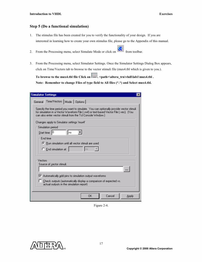
Step 5 (Do a functional simulation) 1. The stimulus file has been created for you to verify the functionality of your design. If you are
interested in learning how to create your own stimulus file, please go to the Appendix of this manual.
2. From the Processing menu, select Simulate Mode or click on from toolbar.
3. From the Processing menu, select Simulator Settings. Once the Simulator Settings Dialog Box appears,
click on Time/Vectors tab to browse to the vector stimuli file (mux4.tbl which is given to you.).
To browse to the mux4.tbl file Click on . <path>\altera_trn\vhdl\lab1\mux4.tbl .
Note: Remember to change Files of type field to All files (*.*) and Select mux4.tbl.
Figure 2-4.

Exercises Introduction to VHDL
Copyright © 2000 Altera Corporation
18
4. In the Simulator Settings Dialog Box. Click on Mode tab. Change the simulation mode to be
Functional. Click OK to close the Simulator Settings Dialog Box.
Figure 2-5.
5. From the Processing menu Select Run Simulation or Click on . When you see the message,
“Simulation was successful”, click ok.
6. Check to see if you get the same results shown in Figure 2.6.
7. The stimulus file has been created for you to verify the functionality of your design. If you are
interested in learning how to create your own stimulus file, please go to the Appendix of this manual.

Introduction to VHDL Exercises
Copyright © 2000 Altera Corporation 19
Figure 2-6.
Step 6 (Close the simulation waveform)
1. Close the simulation waveform window.
2. Switch back to the compile mode
Step 7 (Close the project)
1. From the File menu select Close project option to close the project.

Exercises Introduction to VHDL
Copyright © 2000 Altera Corporation
20

Introduction to VHDL Exercises
Copyright © 2000 Altera Corporation 21
Exercise 3

Exercises Introduction to VHDL
Copyright © 2000 Altera Corporation
22
Exercise 3
Objective: Build a 7-segment display using CASE statement. The 7-segment display shall display 0, 1, 2, 3, and E.
INPUTS OUTPUTS
IN2 IN1 IN0 A b c d e F g DISPLAY 0 0 0 1 1 1 1 1 1 0 0 0 0 1 0 1 1 0 0 0 0 1 0 1 0 1 1 0 1 1 0 1 2 0 1 1 1 1 1 1 0 0 1 3 1 X X 1 0 0 1 1 1 1 E
Figure 3-1.
The input input is declared as STD_LOGIC_VECTOR(2 DOWNTO 0). The outputs a, b, c, d, e, f, g are declared as STD_LOGIC.
Step 1 (Ask the instructor for the <pathname>) 1. <pathname> is________________________________ 2. Use this <pathname> pathname for this Lab Step 2 (Create new project and open VHDL text editor file) Create a project by using the New Project Wizard. To create a project using the New Project Wizard, please follow the following steps:
1. Select New Project Wizard from the File menu. The first time you open the New Project Wizard, it shows the introduction page; you can click Next to proceed to the first page of the wizard.
2. Type the directory name or select the directory with Browse . The directory name has been provided by the instructor in step1.
Introduction to VHDL Exercises
Copyright © 2000 Altera Corporation 23
3. Type a name for the project in the project name box. For this lab, type seven.
4. Type seven as the name of the top-level design entity of the project in the top-level design entry box.
5. Click Next. The second page of the New Project Wizard appears.
6. At this point, there is no file to add because we will create seven source file.
7. Click Next. The summary page appears. The summary page gives information about your project
8. Click Finish. You have just finished the project creation. You should see the top-level entity (seven) in the Compilation Hierarchies tab of the Project Navigator window.
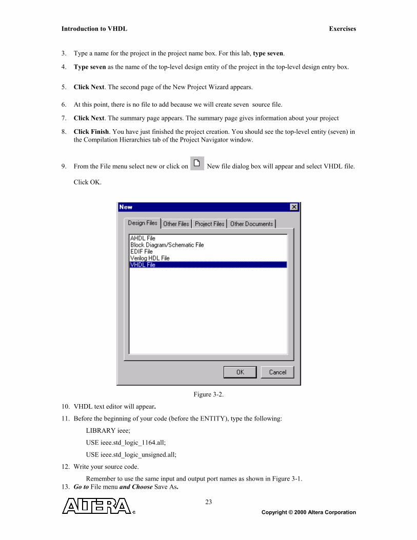
9. From the File menu select new or click on New file dialog box will appear and select VHDL file.
Click OK.
Figure 3-2.
10. VHDL text editor will appear.
11. Before the beginning of your code (before the ENTITY), type the following:
LIBRARY ieee;
USE ieee.std_logic_1164.all;
USE ieee.std_logic_unsigned.all;
12. Write your source code.
Remember to use the same input and output port names as shown in Figure 3-1. 13. Go to File menu and Choose Save As.

Exercises Introduction to VHDL
Copyright © 2000 Altera Corporation
24
Save new VHDL text file to <path>\altera_trn\vhdl\lab3\seven.vhd. Step 3 (Save and check design)
Click on Start Analysis & Elaboration .
This will save and check for syntax and semantic errors for the file seven.vhd. When you see the message
“Analysis and elaboration was successful”, click OK.
Step 4 (Do a functional compilation) 1. From the Processing menu select Compiler Settings. In the dialog box select Mode tab and Click on
Netlist extraction and synthesis only, including estimated timing. Leave other settings as defaults.
Figure 3-3.
2. Click OK to close the Compiler Settings Dialog Box.

Introduction to VHDL Exercises
Copyright © 2000 Altera Corporation 25
3. From the Processing menu, select Start Compilation or click on . When you see the message
“Netlist extraction and synthesis process was successful”, click OK.
Step 5 (Do a functional simulation) 1. The stimulus file has been created for you to verify the functionality of your design. If you are
interested in learning how to create your own stimulus file, please go to the Appendix of this manual.
2. From the Processing menu, select Simulate Mode or click on from toolbar.
3. From the Processing menu, select Simulator Settings. Once Simulator Settings Dialog Box appears,
click on Time/Vectors tab to browse to the vector stimuli file (seven.tbl which is given to you.).
To browse to the seven.tbl file Click on . <path>\altera_trn\vhdl\lab3\seven.tbl .
Note: Remember to change Files of type field to All files (*.*) and Select seven.tbl.
Figure 3-4.
4. In the Simulator Settings Dialog Box. click on Mode tab. Change the simulation mode to be Functional.
Click OK to close the Simulator Settings Dialog Box.

Exercises Introduction to VHDL
Copyright © 2000 Altera Corporation
26
Figure 3-5.
5. From the Processing menu Select Run Simulation or Click on . When you see the message,
“Simulation was successful”, click ok. 6. Check to see if you get the same results shown in Figure 3-6.

Introduction to VHDL Exercises
Copyright © 2000 Altera Corporation 27
Figure 3-6.
Step 6 (Close the simulation waveform)
1. Close the simulation waveform window.
2. Switch back to the compile mode
Step 7 (Close the project)
1. From the File menu select Close project option to close the project.

Exercises Introduction to VHDL
Copyright © 2000 Altera Corporation
28

Introduction to VHDL Exercises
Copyright © 2000 Altera Corporation 29
Exercise 4
Exercises Introduction to VHDL
Copyright © 2000 Altera Corporation
30
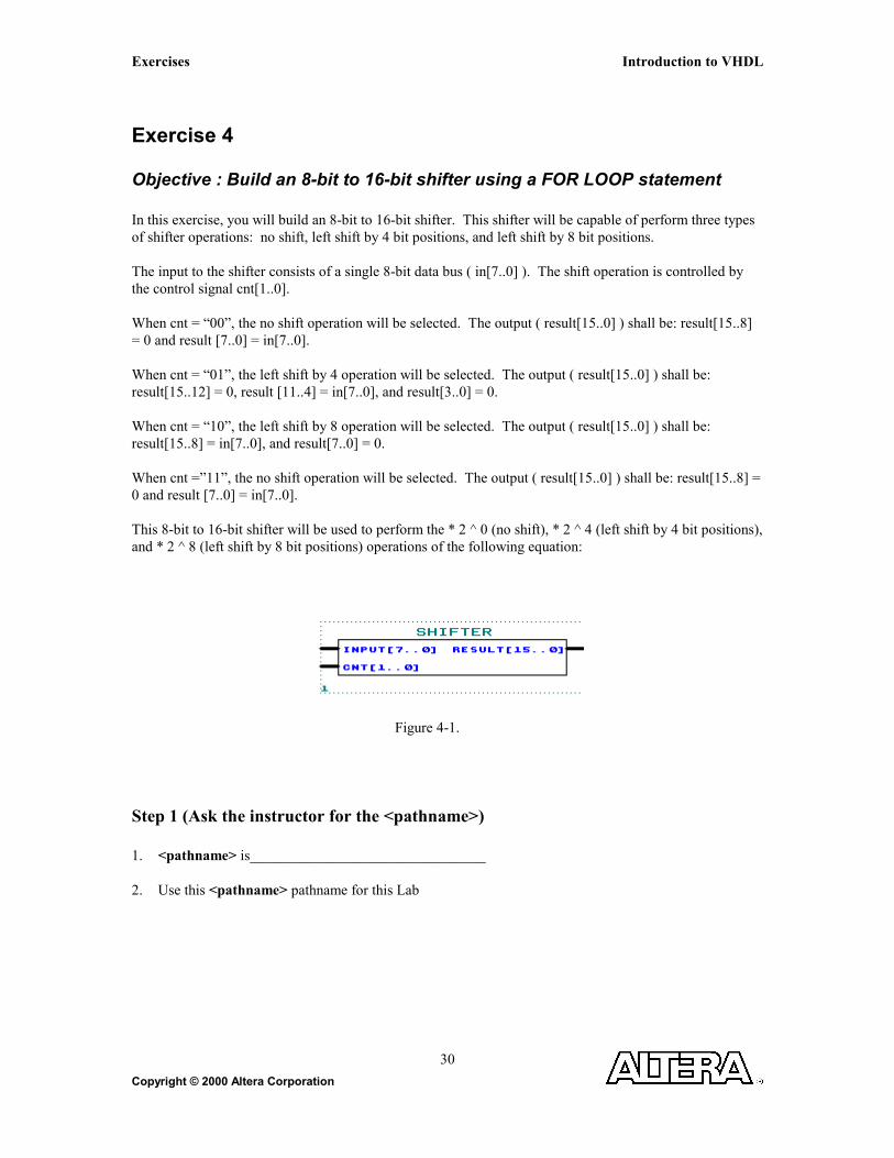
Exercise 4
Objective : Build an 8-bit to 16-bit shifter using a FOR LOOP statement In this exercise, you will build an 8-bit to 16-bit shifter. This shifter will be capable of perform three types of shifter operations: no shift, left shift by 4 bit positions, and left shift by 8 bit positions. The input to the shifter consists of a single 8-bit data bus ( in[7..0] ). The shift operation is controlled by the control signal cnt[1..0]. When cnt = “00”, the no shift operation will be selected. The output ( result[15..0] ) shall be: result[15..8] = 0 and result [7..0] = in[7..0]. When cnt = “01”, the left shift by 4 operation will be selected. The output ( result[15..0] ) shall be: result[15..12] = 0, result [11..4] = in[7..0], and result[3..0] = 0. When cnt = “10”, the left shift by 8 operation will be selected. The output ( result[15..0] ) shall be: result[15..8] = in[7..0], and result[7..0] = 0. When cnt =”11”, the no shift operation will be selected. The output ( result[15..0] ) shall be: result[15..8] = 0 and result [7..0] = in[7..0]. This 8-bit to 16-bit shifter will be used to perform the * 2 ^ 0 (no shift), * 2 ^ 4 (left shift by 4 bit positions), and * 2 ^ 8 (left shift by 8 bit positions) operations of the following equation:
Figure 4-1. Step 1 (Ask the instructor for the <pathname>) 1. <pathname> is________________________________ 2. Use this <pathname> pathname for this Lab

Introduction to VHDL Exercises
Copyright © 2000 Altera Corporation 31
Step 2 (Create new project and open VHDL text editor file) Create a project by using the New Project Wizard. To create a project using the New Project Wizard, please follow the following steps:
1. Select New Project Wizard from the File menu. The first time you open the New Project Wizard, it shows the introduction page; you can click Next to proceed to the first page of the wizard.
2. Type the directory name or select the directory with Browse . The directory name has been provided by the instructor in step1.
3. Type a name for the project in the project name box. For this lab, type shifter.
4. Type shifter as the name of the top-level design entity of the project in the top-level design entry box.
5. Click Next. The second page of the New Project Wizard appears.
6. At this point, there is no file to add because we will create shifter source file.
7. Click Next. The summary page appears. The summary page gives information about your project
8. Click Finish. You have just finished the project creation. You should see the top-level entity (shifter) in the Compilation Hierarchies tab of the Project Navigator window.
9. From the File menu select new or click on . New file dialog box will appear and select VHDL
file. Click OK.
Figure 4-2.

Exercises Introduction to VHDL
Copyright © 2000 Altera Corporation
32
10. VHDL text editor will appear.
11. Before the beginning of your code (before the ENTITY), type the following:
LIBRARY ieee;
USE ieee.std_logic_1164.all;
USE ieee.std_logic_unsigned.all;
12. Write your source code.
Remember to use the same input and output port names as shown in Figure 4-1.
13 Go to File menu and Choose Save As.
Save new VHDL text file to <path>\altera_trn\vhdl\lab4\shifter.vhd.
Step 3 (Save and check design)
Click on Start Analysis & Elaboration .
This will save and check for syntax and semantic errors for the file shifter.vhd. When you see the message
“Analysis and elaboration was successful”, click OK.
Introduction to VHDL Exercises
Copyright © 2000 Altera Corporation 33
Step 4 (Do a functional compilation) 1. From the Processing menu select Compiler Settings. In the dialog box select Mode tab and click on
Netlist extraction and synthesis only, including estimated timing. Leave other settings as defaults.
Figure 4-3.
2. Click OK to close the Compiler Settings Dialog Box.
3. From the Processing menu, select Start Compilation or click on . When you see the message
“Netlist extraction and synthesis process was successful”, click ok.
Step 5 (Do a functional simulation) 1. The stimulus file has been created for you to verify the functionality of your design. If you are
interested in learning how to create your own stimulus file, please go to the Appendix of this manual.
2. From the Processing menu, select Simulate Mode or click on from toolbar.

Exercises Introduction to VHDL
Copyright © 2000 Altera Corporation
34
3. From the Processing menu, select Simulator Settings. Once Simulator Settings Dialog Box appears,
click on Time/Vectors tab to browse to the vector stimuli file (shifter.tbl which is given to you.).
To browse to the shifter.tbl file Click on . <path>\altera_trn\vhdl\lab4\shifter.tbl .
Note: Remember to change Files of type field to All files(*.*) and Select shifter.tbl.
Figure 4-4.
4. In the Simulator Settings Dialog Box. Click on Mode tab. Change the simulation mode to be
Functional. Click OK to close the Simulator Settings Dialog Box.

Introduction to VHDL Exercises
Copyright © 2000 Altera Corporation 35
Figure 4-5.
5. From the Processing menu Select Run Simulation or Click on . When you see the message,
“Simulation was successful”, click ok. 6. Check to see if you get the same results shown in Figure 4-6.

Exercises Introduction to VHDL
Copyright © 2000 Altera Corporation
36
Figure 4-6.
Step 6 (Close the simulation waveform)
1. Close the simulation waveform window.
2. Switch back to the compile mode
Step 7 (Close the project)
1. From the File menu select Close project option to close the project.
Introduction to VHDL Exercises
Copyright © 2000 Altera Corporation 37
Exercise 5

Exercises Introduction to VHDL
Copyright © 2000 Altera Corporation
38
Exercise 5
Objective: Two-part exercise:
Part A -- Build a 16-bit register with synchronous operation
Part B –Build a 2 bit counter with asynchronous operation
Part A Functionality of the 16-bit register:
If clr=’1’ AND clken=’0’, then in_reg will be loaded into register at the rising edge of clock.
Otherwise, if clr=’0’, then the register is cleared at the rising edge of clock.
Note: This is a synchronous clear and clock enable register. Therefore, the IF-THEN
that checks for clear and clock enable should be inside the IF-THEN statement that
that checks for the clock condition.
Figure 5-1.
Step 1 (Ask the instructor for the <pathname>) 1. <pathname> is________________________________ 2. Use this <pathname> pathname for this Lab Step 2 (Create new project and open VHDL text editor file) Create a project by using the New Project Wizard. To create a project using the New Project Wizard, please follow the following steps:
1. Select New Project Wizard from the File menu. The first time you open the New Project Wizard, it shows the introduction page; you can click Next to proceed to the first page of the wizard.

Introduction to VHDL Exercises
Copyright © 2000 Altera Corporation 39
2. Type the directory name or select the directory with Browse . The directory name has been provided by the instructor in step1.
3. Type a name for the project in the project name box. For this lab, type reg.
4. Type reg as the name of the top-level design entity of the project in the top-level design entry box.
5. Click Next. The second page of the New Project Wizard appears.
6. At this point, there is no file to add because we will create reg source file.
7. Click Next. The summary page appears. The summary page gives information about your project
8. Click Finish. You have just finished the project creation. You should see the top-level entity (reg) in the Compilation Hierarchies tab of the Project Navigator window.
9. From the File menu select new or click on . New file dialog box will appear and select VHDL
file.
Figure 5-2.
10. VHDL text editor will appear.
11. Before the beginning of your code (before the ENTITY), type the following:
LIBRARY ieee;
USE ieee.std_logic_1164.all;
USE ieee.std_logic_unsigned.all;

Exercises Introduction to VHDL
Copyright © 2000 Altera Corporation
40
12. Write your source code.
Remember to use the same input and output port names as shown in Figure 5-1.
13. Go to File menu and Choose Save As. Save new VHDL text file to <path>\altera_trn\vhdl\lab5a\reg.vhd.
Step 3 (Save and check design)
Click on Start Analysis & Elaboration .
This will save and check for syntax and semantic errors for the file reg.vhd. When you see the message
“Analysis and elaboration was successful”, click OK.

Introduction to VHDL Exercises
Copyright © 2000 Altera Corporation 41
Step 4 (Do a functional compilation)
1. From the Processing menu select Compiler Settings. In the dialog box select Mode tab and click on
Netlist extraction and synthesis only, including estimated timing. Leave other settings as defaults.
Figure 5-3.
2. Click OK to close the Compiler Settings Dialog Box.
8. From the Processing menu, select Start Compilation or click on . When you see the message
“Netlist extraction and synthesis process was successful”, click OK.
Step 5 (Do a functional simulation) 1. The stimulus file has been created for you to verify the functionality of your design. If you are
interested in learning how to create your own stimulus file, please go to the Appendix of this manual.
2. From the Processing menu, select Simulate Mode or click on from toolbar.
Exercises Introduction to VHDL
Copyright © 2000 Altera Corporation
42
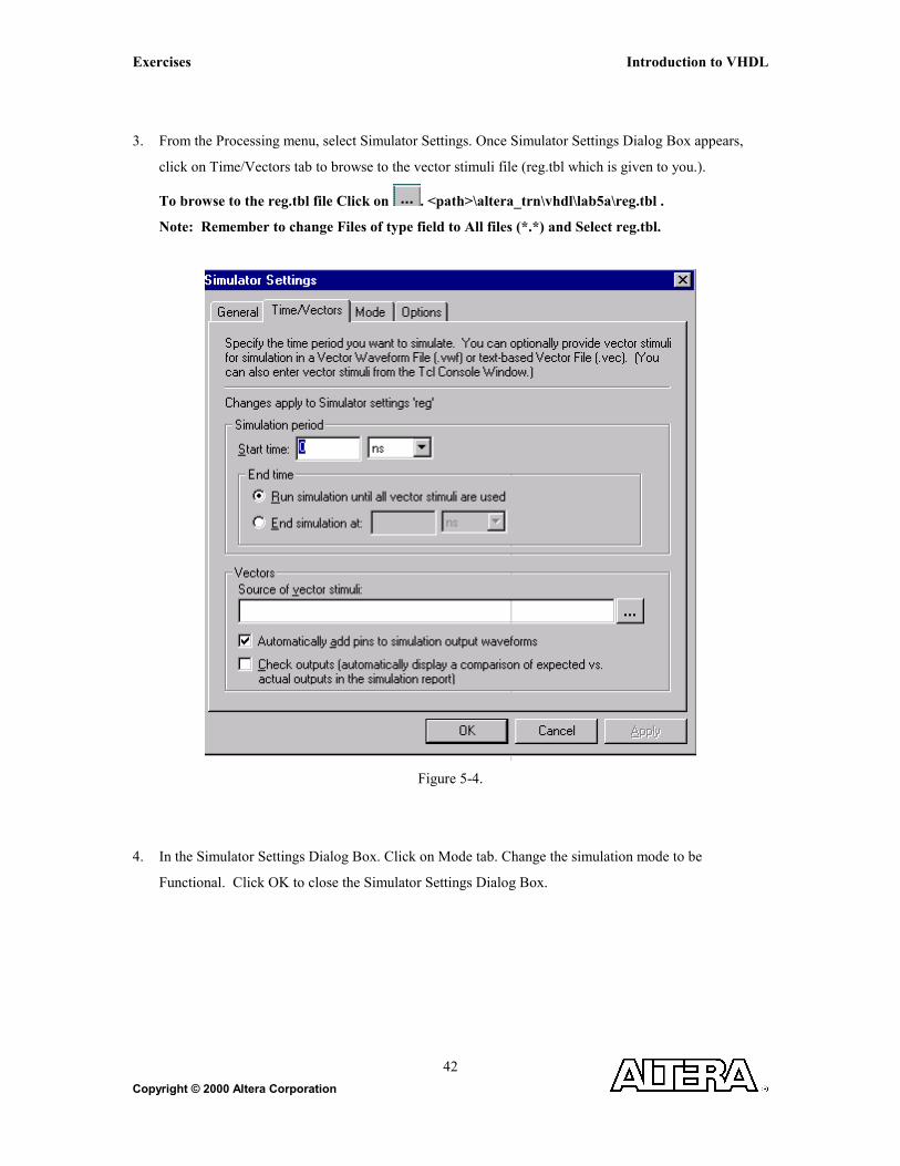
3. From the Processing menu, select Simulator Settings. Once Simulator Settings Dialog Box appears,
click on Time/Vectors tab to browse to the vector stimuli file (reg.tbl which is given to you.).
To browse to the reg.tbl file Click on . <path>\altera_trn\vhdl\lab5a\reg.tbl .
Note: Remember to change Files of type field to All files (*.*) and Select reg.tbl.
Figure 5-4.
4. In the Simulator Settings Dialog Box. Click on Mode tab. Change the simulation mode to be
Functional. Click OK to close the Simulator Settings Dialog Box.

Introduction to VHDL Exercises
Copyright © 2000 Altera Corporation 43
Figure 5-5
5. From the Processing menu Select Run Simulation or Click on . When you see the message,
“Simulation was successful”, click ok.
6. Check to see if you get the same results shown in Figure 5-6.

Exercises Introduction to VHDL
Copyright © 2000 Altera Corporation
44
Figure 5-6.
Step 6 (Close the simulation waveform)
1. Close the simulation waveform window.
2. Switch back to the compile mode
Step 7 (Close the project)
1. From the File menu select Close project option to close the project.
Introduction to VHDL Exercises
Copyright © 2000 Altera Corporation 45
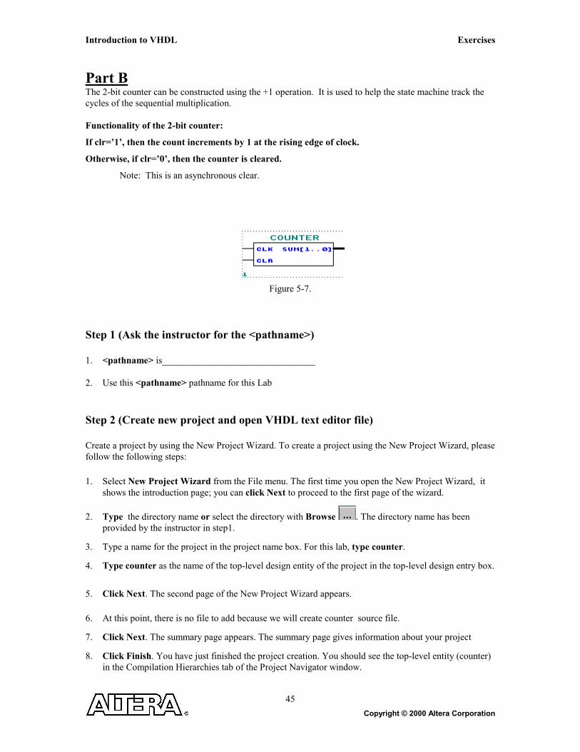
Part B The 2-bit counter can be constructed using the +1 operation. It is used to help the state machine track the cycles of the sequential multiplication. Functionality of the 2-bit counter:
If clr=’1’, then the count increments by 1 at the rising edge of clock.
Otherwise, if clr=’0’, then the counter is cleared.
Note: This is an asynchronous clear.
Figure 5-7.
Step 1 (Ask the instructor for the <pathname>) 1. <pathname> is________________________________ 2. Use this <pathname> pathname for this Lab Step 2 (Create new project and open VHDL text editor file) Create a project by using the New Project Wizard. To create a project using the New Project Wizard, please follow the following steps:
1. Select New Project Wizard from the File menu. The first time you open the New Project Wizard, it shows the introduction page; you can click Next to proceed to the first page of the wizard.
2. Type the directory name or select the directory with Browse . The directory name has been provided by the instructor in step1.
3. Type a name for the project in the project name box. For this lab, type counter.
4. Type counter as the name of the top-level design entity of the project in the top-level design entry box.
5. Click Next. The second page of the New Project Wizard appears.
6. At this point, there is no file to add because we will create counter source file.
7. Click Next. The summary page appears. The summary page gives information about your project
8. Click Finish. You have just finished the project creation. You should see the top-level entity (counter) in the Compilation Hierarchies tab of the Project Navigator window.

Exercises Introduction to VHDL
Copyright © 2000 Altera Corporation
46
9. From the File menu select new or click on . New file dialog box will appear and select VHDL
file.
Figure 5-8.
10. VHDL text editor will appear.
11. Before the beginning of your code (before the ENTITY), type the following:
LIBRARY ieee;
USE ieee.std_logic_1164.all;
USE ieee.std_logic_unsigned.all;
12. Write your source code.
Remember to use the same input and output port names as shown in Figure 5-7. 13. Go to File menu and Choose Save As.
Save new VHDL text file to <path>\altera_trn\vhdl\lab5b\counter.vhd.

Introduction to VHDL Exercises
Copyright © 2000 Altera Corporation 47
Step 3 (Save and check design)
Click on Start Analysis & Elaboration .
This will save and check for syntax and semantic errors for the file counter.vhd. When you see the message
“Analysis and elaboration was successful”, click OK.
Exercises Introduction to VHDL
Copyright © 2000 Altera Corporation
48
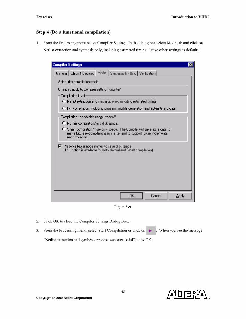
Step 4 (Do a functional compilation) 1. From the Processing menu select Compiler Settings. In the dialog box select Mode tab and click on
Netlist extraction and synthesis only, including estimated timing. Leave other settings as defaults.
Figure 5-9.
2. Click OK to close the Compiler Settings Dialog Box.
3. From the Processing menu, select Start Compilation or click on . When you see the message
“Netlist extraction and synthesis process was successful”, click OK.

Introduction to VHDL Exercises
Copyright © 2000 Altera Corporation 49
Step 5 (Do a functional simulation) 1. The stimulus file has been created for you to verify the functionality of your design. If you are
interested in learning how to create your own stimulus file, please go to the Appendix of this manual.
2. From the Processing menu, select Simulate Mode or click on from toolbar.
3. From the Processing menu, select Simulator Settings. Once Simulator Settings Dialog Box appears,
click on Time/Vectors tab to browse to the vector stimuli file (counter.tbl which is given to you.).
To browse to the counter.tbl file Click on . <path>\altera_trn\vhdl\lab5b\counter.tbl .
Note: Remember to change Files of type field to All files (*.*) and Select counter.tbl.
Figure 5-10
4. In the Simulator Settings Dialog Box. Click on Mode tab. Change the simulation mode to be
Functional. Click OK to close the Simulator Settings Dialog Box.

Exercises Introduction to VHDL
Copyright © 2000 Altera Corporation
50
Figure 5-11.
5. From the Processing menu select Run Simulation or click on . When you see the message,
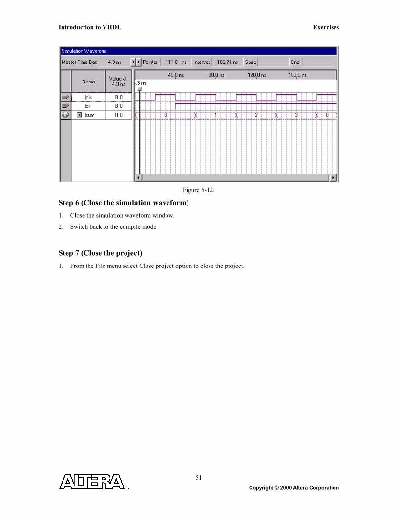
“Simulation was successful”, click ok. 6. Check to see if you get the same results shown in Figure 5-12.
Introduction to VHDL Exercises
Copyright © 2000 Altera Corporation 51
Figure 5-12.
Step 6 (Close the simulation waveform)
1. Close the simulation waveform window.
2. Switch back to the compile mode
Step 7 (Close the project)
1. From the File menu select Close project option to close the project.

Exercises Introduction to VHDL
Copyright © 2000 Altera Corporation
52
Introduction to VHDL Exercises
Copyright © 2000 Altera Corporation 53
Exercise 6

Exercises Introduction to VHDL
Copyright © 2000 Altera Corporation
54
Exercise 6
Objective: Three-part exercise:
Part A – Examine the controlling state machine
Part B – Build a 4x4 multiplier using LPM_MULT
Part C – Putting it all together by declaring and instantiating the lower-level components
Part A You have now completed building all of the components necessary to build the 8x8 multiplier, except for the controlling state machine and the 4x4 multiplier (Part B). Due to time, the controlling state machine has been written for you and is located in <path>\altera_trn\vhdl\lab6a\control.v. This state machine will manage all the operation that occurs within the 8 X 8 multiplier. The state machine will perform the ( (a[3..0] * b[3..0] ) * 2 ^ 0 ) multiplication in the first cycle (LSB state) after the input signal start becomes a ‘1’. This intermediate result is saved in an accumulator. In the second clock cycle (MID state), the ( ( a[3..0] * b[7..4] ) * 2 ^ 4 ) multiplication is performed. The multiplication result is added with the content of the accumulator and clocked back into the accumulator. In the third clock cycle (MID state), the ( ( a[7..4] * b[3..0] ) * 2 ^ 4 ) multiplication is performed. The multiplication result is added with the content of the accumulator and clocked back into the accumulator. In the fourth clock cycle (MSB state), the ( (a[7..4] * b[7..4] ) * 2 ^ 8 ) multiplication is performed. The multiplication result is added with the content of the accumulator and clocked back into the accumulator. This result is the final result: result[15..0] = a [7..0] * b[7..0] = ( ( a[7..4] * b[7..4] ) * 2 ^ 8 ) + ( ( a[7..4] * b[3..0] ) * 2 ^ 4 ) + ( ( a[3..0] * b[7..4] ) * 2 ^ 4 ) + ( ( a[3..0] * b[3..0] ) * 2 ^ 0 ) NOTE: There are two inputs to the state machine start and count[1..0]. The start signal is a single cycle high-true signal. When start becomes a ‘1’, it indicates that multiplication can begin at next clock cycle. The start signal can only be asserted for one clock cycle. The start signal shall stay a ‘0’ until next 8 x 8 multiplication is to be performed. The count[1..0] signal is the output of a free running 2-bit counter. The count[1..0] signal is synchronously initialized by the start signal. Count[1..0] is used by the state machine to track the cycles of the multiplication. Please also note that this is NOT the optimal design. The state machine design as you see it is intended for exercising your VHDL skills and not the ability to perform optimum solution.

Introduction to VHDL Exercises
Copyright © 2000 Altera Corporation 55
Figure 6-1.
IDLEstate_out[2..0]=000
LSBstate_out[2..0]=001
MIDstate_out[2..0]=010
START=1COUNT=X---------------in_sel[1..0]=Xshif[1..0]=xdone=0clken=1regclr=0
START=0COUNT=X---------------in_sel[1..0]=Xshif[1..0]=xdone=0clken=1regclr=1
START=0COUNT=0---------------in_sel[1..0]=0shif[1..0]=0done=0clken=0regclr=1
MSBstate_out[2..0]=011
START=0COUNT=2---------------in_sel[1..0]=2shif[1..0]=1done=0clken=0regclr=1
START=0COUNT=3---------------in_sel[1..0]=3shif[1..0]=2done=1clken=0regclr=1
START=0COUNT=1---------------in_sel[1..0]=1shif[1..0]=1done=0clken=0regclr=1
ERRstate_out[2..0]=100
others---------------in_sel[1..0]=xshif[1..0]=xdone=0clken=1regclr=1
others---------------in_sel[1..0]=xshif[1..0]=xdone=0clken=1regclr=1
others---------------in_sel[1..0]=xshif[1..0]=xdone=0clken=1regclr=1
START=1COUNT=x---------------in_sel[1..0]=xshif[1..0]=xdone=0clken=1regclr=0
others---------------in_sel[1..0]=xshif[1..0]=xdone=0clken=1regclr=1
X means a “don’t care” in this state diagram.

Exercises Introduction to VHDL
Copyright © 2000 Altera Corporation
56
Part B The last component you will build is a 4x4 multiplier. You will use the LPM_MULT supplied by Altera to build a multiplier with a 4-bit multiplicands and an 8-bit result output.
Figure 6-2.
Step 1 (Ask the instructor for the <pathname>) 1. <pathname> is________________________________ 2. Use this <pathname> pathname for this Lab Step 2 (Create new project and open VHDL text editor file) Create a project by using the New Project Wizard. To create a project using the New Project Wizard, please follow the following steps:
1. Select New Project Wizard from the File menu. The first time you open the New Project Wizard, it shows the introduction page; you can click Next to proceed to the first page of the wizard.
2. Type the directory name or select the directory with Browse . The directory name has been provided by the instructor in step1.
3. Type a name for the project in the project name box. For this lab, type mult4x4.
4. Type mult4x4 as the name of the top-level design entity of the project in the top-level design entry box.
5. Click Next. The second page of the New Project Wizard appears.
6. At this point, there is no file to add because we will create mult4x4 source file.
7. Click Next. The summary page appears. The summary page gives information about your project
8. Click Finish. You have just finished the project creation. You should see the top-level entity (mult4x4) in the Compilation Hierarchies tab of the Project Navigator window.

Introduction to VHDL Exercises
Copyright © 2000 Altera Corporation 57
9. From the file menu select new or click on . New file dialog box will appear and select VHDL
file. Click OK.
Figure 6-3.
10. VHDL text editor will appear.
11. Before the beginning of your code (before the ENTITY), type the following:
LIBRARY ieee;
USE ieee.std_logic_1164.all;
USE ieee.std_logic_unsigned.all;
12. Write your source code.
Remember to use the same input and output port names as shown in Figure 6-2. 13. Go to File menu and Choose Save As.
Save new VHDL text file to <path>\altera_trn\vhdl\lab6b\mult4x4.vhd.

Exercises Introduction to VHDL
Copyright © 2000 Altera Corporation
58
Step 3 (Save and check design)
Click on Start Analysis & Elaboration .
This will save and check for syntax and semantic errors for the file mult4x4.vhd. When you see the message
“Analysis and elaboration was successful”, click OK.
Step 4 (Do a functional compilation) 1. From the Processing menu select Compiler Settings. In the dialog box select Mode tab and click on
Netlist extraction and synthesis only, including estimated timing. Leave other settings as defaults.
Figure 6-4.
Introduction to VHDL Exercises
Copyright © 2000 Altera Corporation 59
2. Click OK to close the Compiler Settings Dialog Box.
3. From the Processing menu, select Start Compilation or click on . When you see the message
“Netlist extraction and synthesis process was successful”, click OK.
Step 5 (Do a functional simulation) 1. The stimulus file has been created for you to verify the functionality of your design. If you are
interested in learning how to create your own stimulus file, please go to the Appendix of this manual.
2. From the Processing menu, select Simulate Mode or click on from toolbar.
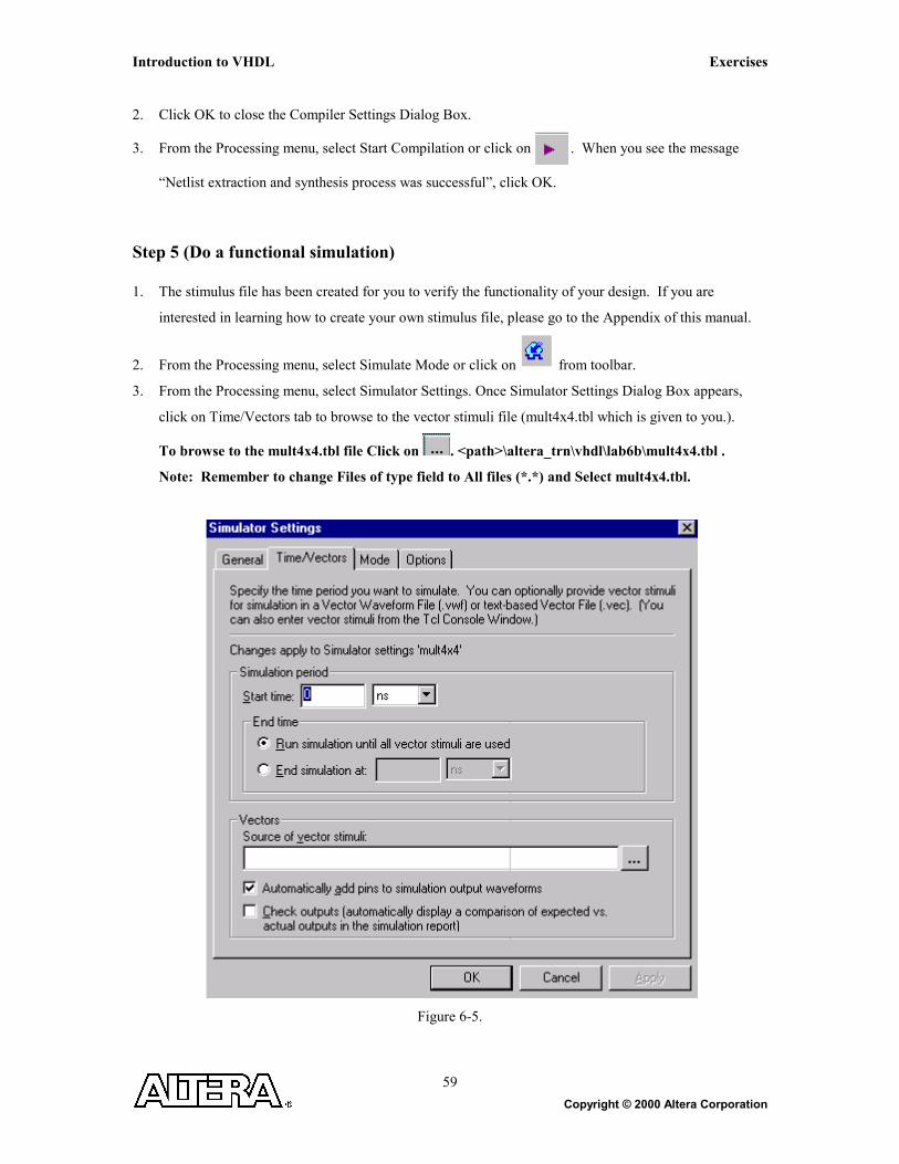
3. From the Processing menu, select Simulator Settings. Once Simulator Settings Dialog Box appears,
click on Time/Vectors tab to browse to the vector stimuli file (mult4x4.tbl which is given to you.).
To browse to the mult4x4.tbl file Click on . <path>\altera_trn\vhdl\lab6b\mult4x4.tbl .
Note: Remember to change Files of type field to All files (*.*) and Select mult4x4.tbl.
Figure 6-5.
Exercises Introduction to VHDL
Copyright © 2000 Altera Corporation
60
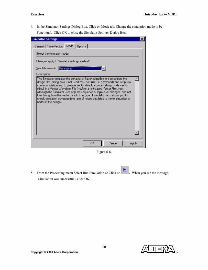
4. In the Simulator Settings Dialog Box. Click on Mode tab. Change the simulation mode to be
Functional. Click OK to close the Simulator Settings Dialog Box.
Figure 6-6.
5. From the Processing menu Select Run Simulation or Click on . When you see the message,
“Simulation was successful”, click OK.

Introduction to VHDL Exercises
Copyright © 2000 Altera Corporation 61
6. Check to see if you get the same results shown in Figure 6-7.
Figure 6-7.
Step 6 (Close the simulation waveform)
1. Close the simulation waveform window.
2. Switch back to the compile mode
Step 7 (Close the project)
1. From the File menu select Close project option to close the project.

Exercises Introduction to VHDL
Copyright © 2000 Altera Corporation
62
Part C You have now completed building all of the components necessary to build the 8x8 multiplier. Making use of the knowledge you have gained up to this point, you should instantiate each component in a top-level design and connect all signals as shown in Figure 6-4. You have successfully completed the Introduction to VHDL class once your top-level design is compiled and simulated correctly. Congratulations! You have completed the implementation of the following 8x8 multiplier. result[15..0] = a [7..0] * b[7..0] = ( ( a[7..4] * b[7..4] ) * 2 ^ 8 ) + ( ( a[7..4] * b[3..0] ) * 2 ^ 4 ) + ( ( a[3..0] * b[7..4] ) * 2 ^ 4 ) + ( ( a[3..0] * b[3..0] ) * 2 ^ 0 )

Introduction to VHDL Exercises
Copyright © 2000 Altera Corporation 63
Figure 6-8.

Exercises Introduction to VHDL
Copyright © 2000 Altera Corporation
64
Step 1 (Ask the instructor for the <pathname>) 1. <pathname> is________________________________ 2. Use this <pathname> pathname for this Lab Step 2 (Create new project and open VHDL text editor file) Create a project by using the New Project Wizard. To create a project using the New Project Wizard, please follow the following steps:
1. Select New Project Wizard from the File menu. The first time you open the New Project Wizard, it shows the introduction page; you can click Next to proceed to the first page of the wizard.
2. Type the directory name or select the directory with Browse . The directory name has been provided by the instructor in step1.
3. Type a name for the project in the project name box. For this lab, type mult8x8.
4. Type mult8x8 as the name of the top-level design entity of the project in the top-level design entry box.
5. Click Next. The second page of the New Project Wizard appears.
6. At this point, there is no file to add because we will create mult8x8 source file
7. Click Next. The summary page appears. The summary page gives information about your project
8. Click Finish. You have just finished the project creation. You should see the top-level entity (mult8x8) in the Compilation Hierarchies tab of the Project Navigator window.

Introduction to VHDL Exercises
Copyright © 2000 Altera Corporation 65
9. From the File menu select new or click on . New file dialog box will appear and select VHDL
file. Click OK.
Figure 6-9.
10. VHDL text editor will appear.
11. Before the beginning of your code (before the ENTITY), type the following:
LIBRARY ieee;
USE ieee.std_logic_1164.all;
USE ieee.std_logic_unsigned.all;
12. Write your source code.
Remember to use the same input and output port names as shown in Figure 6-8. 13. Go to File menu and Choose Save As.
Save new VHDL text file to <path>\altera_trn\vhdl\lab6c\mult8x8.vhd. 14. The lower-level components have been created in different directories than the current directory.
In order for Quartus II to find these lower-level components, it must have a search path.
Therefore, you must do the following:
Go to Project menu and Choose General Settings. From General Settings choose User
Libraries tab. Browse the file locations :
a) Choose the directory structure <path>\altera_trn\vhdl\lab1. Click on open.

Exercises Introduction to VHDL
Copyright © 2000 Altera Corporation
66
b) Choose the directory structure <path>\altera_trn\vhdl\lab2. Click on open.
c) Choose the directory structure <path>\altera_trn\vhdl\lab3. Click on open.
d) Choose the directory structure <path>\altera_trn\vhdl\lab4. Click on open.
e) Choose the directory structure <path>\altera_trn\vhdl\lab5a. Click on open.
f) Choose the directory structure <path>\altera_trn\vhdl\lab5b. Click on open.
g) Choose the directory structure <path>\altera_trn\vhdl\lab6b. Click on open.
h) Choose the directory structure <path>\altera_trn\vhdl\lab6c. Click on open.
i) Click OK.
15. You will need to modify adder.vhd to uncomment the library commands that were commented out from
Exercise 1. Go to Exercise 1, page 11 and reverse step 2 and then do step 3.
Step 3 (Save and check design)
Save and check mult8x8.vhd.
Save and check checks for syntax and semantic errors. The compiler should stop on the Compiler
Netlist Extractor if there are no error messages. When you see the message “Analysis and elaboration was
successful”, click OK.

Introduction to VHDL Exercises
Copyright © 2000 Altera Corporation 67
Step 4 (Do a functional compilation) 1. From the Processing menu select Compiler Settings. In the dialog box select Mode tab and click on
Netlist extraction and synthesis only, including estimated timing. Leave other settings as defaults.
Figure 6-10.
2. Click OK to close the Compiler Settings Dialog Box.
3. From the Processing menu, select Start Compilation or click on . When you see the message
“Netlist extraction and synthesis process was successful”, click OK.
Exercises Introduction to VHDL
Copyright © 2000 Altera Corporation
68
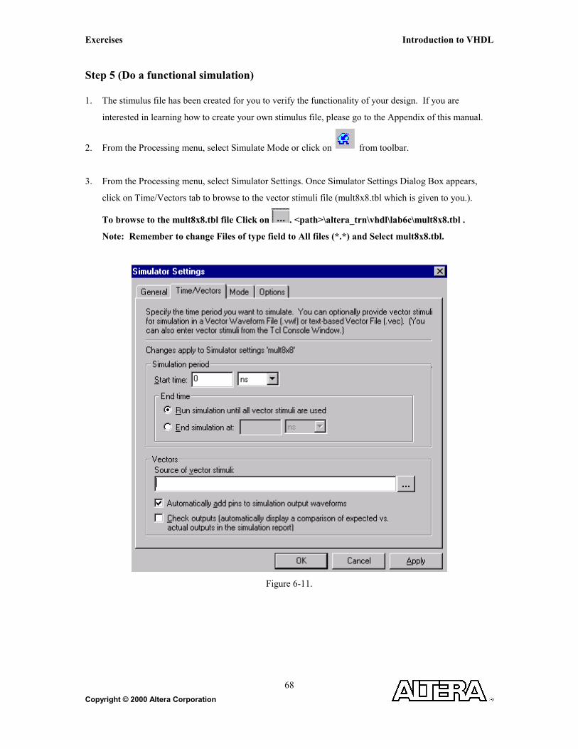
Step 5 (Do a functional simulation) 1. The stimulus file has been created for you to verify the functionality of your design. If you are
interested in learning how to create your own stimulus file, please go to the Appendix of this manual.
2. From the Processing menu, select Simulate Mode or click on from toolbar.
3. From the Processing menu, select Simulator Settings. Once Simulator Settings Dialog Box appears,
click on Time/Vectors tab to browse to the vector stimuli file (mult8x8.tbl which is given to you.).
To browse to the mult8x8.tbl file Click on . <path>\altera_trn\vhdl\lab6c\mult8x8.tbl .
Note: Remember to change Files of type field to All files (*.*) and Select mult8x8.tbl.
Figure 6-11.
Introduction to VHDL Exercises
Copyright © 2000 Altera Corporation 69
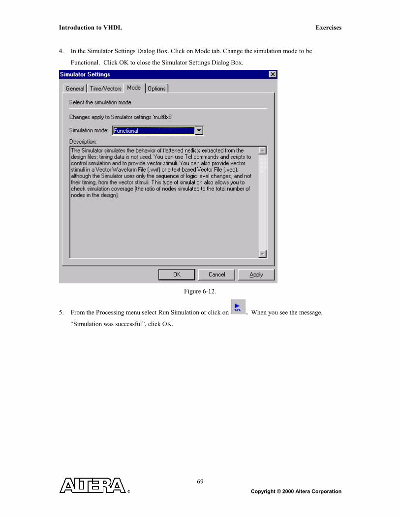
4. In the Simulator Settings Dialog Box. Click on Mode tab. Change the simulation mode to be
Functional. Click OK to close the Simulator Settings Dialog Box.
Figure 6-12.
5. From the Processing menu select Run Simulation or click on . When you see the message,
“Simulation was successful”, click OK.

Exercises Introduction to VHDL
Copyright © 2000 Altera Corporation
70
6. Check to see if you get the same results shown in Figure 6-13.
Figure 6-13.
Step 6 (Close the simulation waveform)
1. Close the simulation waveform window.
2. Switch back to the compile mode
Step 7 (Close the project)
1. From the File menu select Close project option to close the project.

Introduction to VHDL Exercises
Copyright © 2000 Altera Corporation 71
APPENDIX

Exercises Introduction to VHDL
Copyright © 2000 Altera Corporation
72
How to create a stimulus file:
1. Create a new waveform stimulus for simulation. Click on
2. Under Other Files tab: Choose Vector Waveform File
3. Click OK.
4. Enter nodes into the waveform file. Insert menu -> Enter Node or Bus
5. Set the inputs to the appropriate values.
6. Save the file.