quasi-one-dimensional compressible flow across … compressible flow across face seals and narrow...
TRANSCRIPT

QUASI-ONE-DIMENSIONAL COMPRESSIBLE FLOW ACROSS FACE SEALS AND NARROW SLOTS I - Analysis
by John Znk, Luwrence P. Ludwig, und Robert L. Johnson
Lewis Reseurch Center Cleuehnd, Ohio 44135
i fi 1
\ N A T I O N A L AERONAUTICS A N D SPACE A D M I N I S T R A T I O N W A S H I N G T O N , D. C. MAY 1972 a 1 i
https://ntrs.nasa.gov/search.jsp?R=19720017818 2018-05-22T09:04:55+00:00Z

TECH LIBRARY KAFB, NM
1. Report No. NASA TN D-6668
IllllllllllllllIIllllllllllllllllllllllllllll _. ,."",t,,",,L J - lalug 1x0.
I 2. Government Accession No.
9. Performing Organization Name and Address
Lewis Research Center National Aeronautics and Space Administration Cleveland, Ohio 44135
2. Sponsoring Agency Name and Address
National Aeronautics and Space Administration Washington, D. C. 20546
7. Author(s)
10. Work Unit No.
132- 15 11. Contract or Grant No.
13. Type of Report and Period Covered
Technical Note 14. Sponsoring Agency Code
j 8. Performing Organization Report No.
5. Supplementary Notes
- .
6: Abstract
An analysis is presented for compressible fluid flow across shaft face seals and narrow slots. The analysis includes fluid inertia, viscous friction, and entrance losses. Subsonic and choked flow conditions can be predicted and analyzed. The model is valid for both laminar and turbulent flows. Results agree with experiment and with solutions which a r e more limited in applicability. Results show that a parallel film can have a positive film stiffness under choked flow conditions.
Lubrication; Subsonic flow; Choked flow; Laminar flow; Turbulent flow; Seal; Face seal; Sealing dam; Gas bearings
Unclassified - unlimited 7. Key Words (Suggested by Author(s) I
- . -~ 9. Security Classif. (of this report)
Unclassified Unclassified
* For sa le by the Nat iona l T e c h n i c a l Informat ion Service, Spr ingf ie ld , V i rg in ia 22151

QUASI -ONE-DIMENSIONAL COM PRES SI BLE FLOW
ACROSS FACE SEALS AND NARROW SLOTS
I - ANALYSIS
by John Zuk, Lawrence P. Ludwig, and Robert L. Johnson
Lewis Research Center
SUMMARY n
An analysis is presented for compressible fluid flow across gas film shaft face sea ls and narrow slots. method which includes fluid inertia, viscous friction, and entrance losses. friction is accounted for by a mean friction factor. and turbulent flow. Subsonic and choked flow conditions can be analyzed.
ues of this parameter and for low Mach number, the resul ts are identical to the solution for viscous subsonic flow; for small values, the resul ts correspond to orifice flow equa- tions. Results agree with radial flow experiments.
Results show that a parallel film can have a positive f i lm stiffness under choked
The flow is analyzed using a quasi-one-dimensional integral Viscous
The model is valid for both laminar
A seal radial width to film thickness geometric parameter is used. For large val-
flow conditions.
I NT R OD U CT I ON
Shaft sea l systems in advanced aircraf t turbine engines will be operated at speeds, temperatures, and pressures higher than shaft seals currently used. Conventional face seals presently used in gas turbine engines a r e Limited to sliding velocities of about 110 meters per second (350 ft/sec), pressures of about 86 newtons per square centime- ter (125 lb/in. '), and gas temperatures of 700 K (800' F) (ref. 1). Advanced engines, however, will require seals to operate to speeds of 150 meters per second (500 ft/sec) (ref. 2), pressures to 340 newtons per square centimeter (500 lb/in. '), and tempera- tures to 980 K (1300' F) (ref, 3). For face seals operating at these conditions, a posi- tive face separation (no rubbing contact) will be required to achieve long life and relia- bility. A promising approach is the use of gas film seals with self-acting l i f t pads (see

: SEAL RING FACE
OPENING FORCE
CD-10413-15
Figure 1. - Pressure-balanced face seal w i t h sel f -act ing l i f t pads (added f o r axial f i lm stiffness).
fig. 1, refs . 4 and 5, and Seal Description and Models). Since the seals must be pressure balanced, a proper balance of the opening and
closing forces must be achieved with a leakage gap that has tolerable mass leakage. The gap must be small enough s o that the leakage is minimal, but it must be large enough s o that power dissipation, due to shear in the film, and face deformation a r e tolerable. Thus the design of the sealing gap is vital to sea l performance and pressure distribution in the gap and mass leakage through the gap must be analyzed. In this re- port only the sealing dam portion of the seal is analyzed.
The classical viscous, isothermal, subsonic, compressible flow analysis for this problem is well known (e. g. , see Gross, ref. 6). The pressure distribution and mass leakage have been calculated for the parallel film hydrostatic case. Carothers (ref. 7) has conducted compressible flow experiments in thin films of air which a r e flowing radially between parallel plates. The pressure distribution was found for both subsonic and supersonic axial entrance flows. Carothers' geometry, however, was representa- tive of externally pressurized gas bearings rather than seals. Grinell (ref. 8) has the- oretically and experimentally investigated compressible flow in thin passages and has shown agreement between theory and experiment. Mueller (ref. 9) included compres- sibility for the case where there was a restricted bypass orifice flow into the parallel gap, but his analysis did not consider conditions which would yield choked flow in the
2 E-6819

gap. The textbook on mechanical face seals by Mayer (ref. 10) virtually excluded face sea l operation under conditions where fluid compressibility is important.
The objective of this report is to present a mathematical analysis of compressible fluid flow across shaft face seals and narrow slots. The analysis includes fluid inertia, viscous friction, and entrance losses and thus describes both subsonic and choked flow conditions. For specified pressure ratios, film thicknesses, and friction factor varia- tions with Reynolds number, which are used as parametric input, the output variables include mass and volume leakage flow rates, force, center of pressure, and distribu- tions of pressure, density, velocity, temperature, and Mach number.
Seal Description and Models
A conventional face sea l which is pressure (force) balanced is shown in figure 2. In this seal, the pressure drop occurs across a narrowly spaced sealing dam, and the force due to this pressure drop is balanced by a hydrostatic closing force and spring force. For parallel sealing dam surfaces, the force caused by the pressure drop across the sealing dam is inde- pendent of film thickness for low Mach numbers; hence, there is no way of maintaining preselected film thickness which will allow tolerable leakage and still have noncontact operation. Since the force is independent of film thickness, the design also lacks axial film stiffness for sufficient dynamic tracking of the stationary nosepiece with the rotat- ing sea l seat. In order to operate adequately, the seal nosepiece must follow the sea l seat surface under all conditions without surface contact o r excessive increase in film
This configuration, however, has an inherent problem.
p3 Po> p3 Axial mot ion SDrina
f ........... ::::::::: .:.:.:.:.:.:.:. . . . . . . . .
‘0 ~
. . . . . . - 1 .......................................... .:.:.::::::::::i:I_:_:_:.:_:_: ...... :.:.:.:.:.:.:.:.: .... .-.:.: ........... >>:.>>:.:.>> ..................... :: I -/ 1
Figure 2. - Pressure-balanced face seal w i t h n o axial f i lm stiffness.
3

thickness, which would yield high leakage. Some of these conditions a r e axial runout, misalinement, thermal distortion, coning, and dishing.
film stiffness is to add a self-acting gas bearing, such as shrouded Rayleigh step l i f t pads, to the conventional rubbing contact pressure- balanced face seal (see fig. 1 for a sketch and refs. 4 and 5 for details of this concept, design, and test results) . Both the sealing dam force due to the pressure drop across the sealing dam and the self-acting lift pad (gas bearing) force are balanced by the hydrostatic and spring closing forces. The gas bearing has a desirable characteristic whereby the force increases with de- creasing film thickness. If the sea l is perturbed in such a way as to decrease the gap, the additional force generated by the gas bearing will open the gap to the original equili- brium position. In a similar manner, if the gap becomes larger , the gas bearing force decreases, and the closing force will cause the seal gap to re turn to the equilibrium position.
A promising method of maintaining a preselected film thickness and achieving axial
Some Models and Their Limitations
For subsonic flow, variable cross-sectional area, and Mach number < 1/67 (all symbols a r e defined in appendix A), the analysis of reference 11 can be used. This dif- ferential analysis finds a solution for the case where the viscous friction is balanced by the pressure drop and the fluid inertia is negligible. For this condition the entrance pressure drop is small; hence, Po = P1 and P2 = P3 (see fig. 3). The flow is nearly isothermal for the film thickness range studied. The analysis of reference 11 yields the classical cubic dependence of mass flow on film thickness. Also, this analysis enables
,Seal dam ins ide diameter
I T, dA,
0 u u t d u T T tdT p P t d P M MtdM
R 1 X- j - d X L /
F igu re 3. - Model and notat ion of seal ing faces i n c l u d i n g con t ro l volume fo r quasi -one-d imensional flow.
4

small tilts of the sealing dam surfaces to be studied. These small tilts simulate seal face deformations which can occur due to thermal, centrifugal, etc. , effects.
reference 11 becomes important. Also, the flow behaves more as an adiabatic flow than an isothermal flow. The equations (partial differential equations) are relatively complex because of the nonlinearity of the inertia terms; thus an approximate analytical model must be used. In the approximate model presented here, the flow is analyzed as a quasi- one-dimensional flow using a control volume integral analysis.
seal nosepiece, a question arises as to the validity of neglecting the centripetal inertia force which would affect the radial flow. This question was examined in reference 13. It was found that the circumferential rotational flow can be uncoupled from the radial pressure flow when the ratio of rotational velocity to pressure flow velocity is less than 1 / d m 2 . Rotational effects are important for calculating the viscous shear and power dissipation.
It si,, ’! rJe nointed out that the flow in a gas film face seal is qualitatively quite different from the flow in an externally pressurized thrust bearing. Both operate with very small film thicknesses, usually less than 0.0025 centimeter (1 mil). However, gas film face seals are characterized by a small (R2 - R1)/R1 ratio. Also, the inner cavity is a large supply reservoir. Hence, in gas film seals the reservoir pressure does not vary with film thickness. On the other hand, externally pressurized gas thrust bearings a r e characterized by a large (R2 - R1)/R1 ratio. (The large surface a rea is necessary for high load capacity. ) In order to maintain positive film stiffness, compen- sating inlet flow restr ic tors are used. Because of these restrictors, the inlet pressure to the bearing varies significantly with film thickness. As a result of these differences, the flow regimes for the two cases a r e quite different.
For flow approaching Mach 1 (i. e . , choked flow), the inertia force neglected in
Since in gas film face seal applications there is seal seat rotation relative to the
QUASI-ONE-DIMENSIONAL FLOW ANALYSIS
As stated in the previous section, when the radial flow is close to choked or is choked at the exit, the viscous flow analysis in reference 11 is no longer valid. Fluid inertia, neglected in that analysis, becomes important. tial terms necessitates the solution of nonlinear partial differential equations and is therefore not practical for engineering calculations; hence an approximate analytical model will be formulated which will be especially useful for calculating flow conditions near and at choking.
arated by a very narrow gap. Rotational effects on the radial flow are negligible for
The rigorous inclusion of iner-
The geometry is shown in figure 3. Two parallel, coaxial, circular rings are sep-
5

--.---.-I-.-- I 11111 I1111111111 Ill 111 1111.11111111 -= I
most applications (ref. 13). A pressure differential exists between the rings' inner and outer radii. The cavities on either side (i. d. and 0. d. ) of the sealing dam a r e assumed to be constant pressure reservoirs . For subsonic flow, reservoir conditions and the exit ambient pressure are specified. For choked flow, reservoir conditions and an exit Mach number of one are specified.
arately. One par t is an analysis of the seal passage itself, in which the flow is assumed to behave as a constant area, adiabatic flow with friction, while the other par t is an analysis of the entrance flow. The analysis for these two regions is described first fol- lowed by a discussion of the iterative procedure for the complete solution.
The analysis can be separated into two parts, which can then be considered sep-
Constant Area Adiabatic Flow With Frict ion
It is assumed that the flow in the sea l leakage flow region behaves as a constant a r ea adiabatic flow with friction. A quasi- one-dimensional approximation is made wherein it is assumed that the flow properties can be described in te rms of their cross- sectional averages.
The following assumptions have been made in the analysis: (1) The area expansion due to radius increase is neglected.
seals the i.d./o.d. is about 0.98.) (2) The flow is adiabatic. (3) No shaft work is done on or by the system. (4) No potential energy differences are present such as caused by elevation differ-
(5) The fluid behaves as a perfect gas. (6) The sealing surfaces a r e parallel.
(In most mainshaft face
ences.
With these assumptions, the flow is commonly known as Fanno line flow (ref. 15). This analysis is similar to that used by Grinnell (ref. 8) for flow in thin passages. The gov- erning equations when area changes a r e neglected a r e as follows:
Conservation of mass:
M = puA = constant
which reduces to
2 dp 1 du -+ - - = 0 P 2 u2
6

Conservation of energy:
P uL P 2
e + - + - = constant
or
2 U i +- = constant 2
where i is the specific enthalpy. This can be written as
This equation can be reduced to
where the Mach number M = u / d m .
Equation of state:
P = p @ T
or
d P - d p dT P P T - -- +-
Conservation of momentum:
- A d P - rw dAw = M du
(7)
7
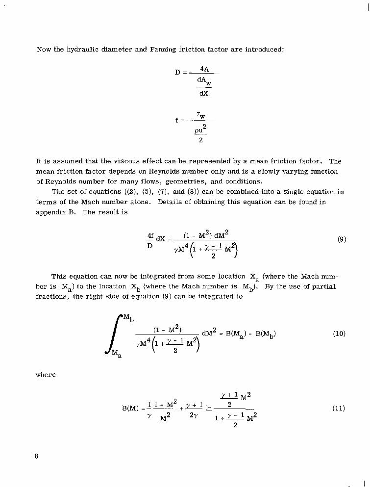
Now the hydraulic diameter and Fanning friction factor a r e introduced:
4A D = 5 dx
2 pu 2
It is assumed that the viscous effect can be represen-zc by a mean friction ,Actor. The mean friction factor depends on Reynolds number only and is a slowly varying function of Reynolds number for many flows, geometries, and conditions.
t e rms of the Mach number alone. appendix B. The result is
The set of equations ((2), (5), (7), and (8)) can be combined into a single equation in Details of obtaining this equation can be found in
4 f d x = (1 - M2) dM2 D yM4 (1 + y-l M2)
2
This equation can now be integrated from some location Xa (where the Mach num- By the use of partial ber is Ma) to the location Xb (where the Mach number is Mb).
fractions, the right side of equation (9) can be integrated to
(l - M2) dM 2 = B(M,) - B(Mb) yM4(l +d M2)
'a 2
where
Y + l M 2 1 1 - M 2 y + l h 2 B(M) = - +-
y - l M 2 M2 2y 1+- 2
8

.R 9 Since the variation of f with X is usually unknown, the integral of the left side of equation (9) cannot be evaluated exactly. However, if f is replaced by an appropriate mean value f, the integration may be performed:
(xb - xa> 47 - 4 /"" f a = - D D
xa
The integration of equation (9) yields
In the computer calculation, it is convenient to define a length
such that
(Note that B(M = 1) = 0. ) The length LN is the length of the sea l (measured from XN) for which the condition at the exit is sonic (choked). It follows, if M1 and M2 a r e the Mach numbers at the inlet and exit of the seal, respectively, that
AR = L1 - L2 (17)
See figure 4.
t o find the pressure at any point in the flow leakage passage as a function of Mach num- The reservoir pressure and exit ambient static pressure a r e known. It is desirable
9
Id

Figure 4. - Lengths and stations used i n the analysis. (Subsonic case i s shown. )
ber. The flow is adiabatic. Thus the stagnation temperature is constant everywhere in the seal; that is,
T O 1 = T02
o r (ref. 15, p. 80)
T1 ( 1+- 7; ' M : ) = T 2 ( 1 + L - M:) 2
From this relation, the continuity equation, the equation of state, and the definition of the Mach numbers, one obtains
p1 M2
p2 M1
Y - 1 1 +- 2 - 1 1 + y i 2
Entrance Flow
If it is assumed that the flow in the entrance region is isentropic and adiabatic, the analysis is straightforward. The adiabatic energy equation is
2 io = il +-
2 u1
10

which can be written as
TO (Y - m; - = 1 + T1 2
By use of the isentropic relation, P/py = constant, and the equation of state, other inlet variables can be found knowing the sealed high pressure reservoir values; for example,
It is well known that entrance flows do not behave as isentropic flows but that an additional pressure drop is present due to viscous friction, turning losses, etc. A prac- t ical way of accounting for the entrance loss is to introduce an empirically determined velocity loss coefficient CL (see appendix C). Hence, equation (22) becomes
2c;
while equation (23) becomes
Under the entrance conditions discussed in appendix C, the entrance velocity loss coefficient CL is related to the head loss coefficient k' commonly used in hydraulics by the relation
11

Iteration Procedure
The procedure for solving the previous equations is an iterative one. The solution is found using a computer program which appears in reference 12. In the iterative pro- cedure, the first step is to solve for the minimum film thickness for which the flow is choked. If the actual f i l m thickness is less than this minimum value, the speed of the flow is less than sonic at the exit and the exit condition is P2 = P3. If the actual film thickness is greater than the minimum for choked flow, the exit flow is sonic and the exit condition is M2 = 1, but the exit pressure is unknown. The details of the procedure a r e as follows:
Choked film thickness evaluation. - When the flow is just choked, it is known that P2 = P3 and M2 = 1. By combining equation (26), the relation for Po/P1, with equa- tion (20), the equation for P1/P2 = (P1/P3) in the seal leakage passage, one obtains
p3 M1
Since Po/P3 is known, the Mach number M1 can then be determined from this equa- tion. Once the Mach number is known, all other flow quantities can be determined. minimum choked film thickness is calculated as follows:
The
(1) A film thickness h is assumed (chosen to be 1 mi l in the computer program). (2) A Reynolds number is calculated from this film thickness. (3) This Reynolds number determines the flow regime, laminar o r turbulent, and --
therefore the friction factor. (f = constant/Ren, where the constant and exponent n are program inputs and depend on whether the flow is laminar or turbulent. )
(4) A film thickness is then calculated by use of equation (16):
4fAR - 2TAR D h
B(M1) =- --
1 2
(29) I

(For radial flow between coaxial parallel disks and parallel plates, the hydraulic &am- eter D = 2h. ) If this h does not agree with the previous h, steps (2) to (4) are repeated until the h's agree. This defines the cri t ical or minimum choked film thickness h* . It should be noted that equation (28) cannot be solved for all values of P0/P3, CL, and y. Consequently, h' cannot be found. This condition arises for very low subsonic flows; hence, the flow is assumed to be subsonic.
Subsonic flow case. - For input film thickness less than the minimum choked film thickness, the flow is subsonic and the exit condition is P2 = P3. In this case it is con- venient to use the length LN defined by equation (14); that is, re fer all quantities to a fictitious length of the seal for which the condition at the exit is sonic (choked). To start the iteration procedure, the entrance Mach number M1 is assumed to be the same as for cri t ical flow. All other quantities at the inlet are then calculated. The value of the friction parameter B(M1) is found from equation (11) and the choking length from equa- tion (16); that is, L1 = B(M1)D/4T. The length L2 can be calculated from L2 = L1 - AR and then the friction parameter B(M2) from equation (11). Once B(M2) is known, the Mach number M2 can be determined and, hence, the pressure P2. This procedure is then repeated with a new Mach number M1 until P2(M1) = P3.
Choked ~ flow case. - For choked flow, the input film thickness is greater than the choking film thickness and the exit condition is Ma = 1. As in the subsonic flow case, the iteration procedure begins with the entrance Mach number assumed to be the choking film thickness entrance Mach number. Again all entrance quantities a r e calculated. friction factor 7 is calculated from the Reynolds number, and the friction parameter B(M1) = 47L/D is calculated from equation (11). The trial flow length L is calculated as
The
If L is not equal to the true flow length AR, the procedure is repeated with a new MI until L does agree with AR.
Calculation of Variables at Intermediate Points
Once the entrance conditions a r e known, the Mach number, temperature, velocity, and pressure a r e determined at each desired location XN along the sea l passage length in the following way:
(1) LN is found from equation (14).
13

(2) B(MN) is calculated from equation (16). (3) MN is found by an iterative solution of equation (11). (4) TN is found from equation (19) where T2 = T* and M2 = 1; hence,
TN =
( Y ) T *
(1 +y-l M i ) 2
(5) The velocity uN is found from the Mach number definition. (6) The density is found from the mass conservation equation (1):
(7) The pressure is found from the perfect gas law, equation (6).
Computer Program
The computer program in reference 12 used to car ry out this analysis is written in FORTRAN IV. The program is described in detail including all input and program vari- ables and output options. problem with computer printout is given. The input and output can be in either the U.S. Customary o r International System of Units.
Program listing and flow charts a r e presented and a sample
Remarks on Physics of Flow
Static pressure drops to overcome flow friction. This pressure drop increases the specific volume of the fluid. Since the a rea change is negligible, the mean velocity must increase as the specific volume increases in order to maintain the same mass flow rate at each section of the leakage path. As the velocity increases the fluid momentum also increases, which requires an additional pressure drop. greater increase in specific volume. leakage path o r until the fluid reaches the maximum (choking) condition which will occur when the Mach number is one a t the exit (exit velocity is sonic). Should the Mach num- ber reach a value of one somewhere along the leakage path interior, it is expected that
This results in a still This process will continue until the end of the
14

behavior similar to duct flow will occur. For duct flow it can be shown that the flow @$ e.;+ Pi process will adjust itself until the point at which the Mach number reaches one is shifted to the exit of the leakage passage. The mass flow rate of the fluid is the maximum which can be handled for a given inlet density and passage cross-sectional area. flow process is known classically as Fanno line flow.
the total sea l pressure drop; however, under choked conditions the entrance velocity head loss is no longer negligible. under choked flow conditions, the exit pressure is larger than the sump pressure and increases with film thickness. sump pressure in the outer cavity. However, these expansion waves do not significantly affect the axial force balance on a seal nosepiece.
As previously stated, in most face seals the area expansion is negligible due to the radius ratios being close to one. Hence, i f the flow becomes choked it will usually be at the exit. Choking can occur at the entrance under some conditions. If there is flow separation at the entrance (due, e . g. , to the flow turning into the sealing faces), there could be a large entrance a rea decrease with choking occurring at the vena contracta. For smaller radius ratios such as those that characterize externally pressurized gas bearings, choking will occur at the entrance.
This
The entrance velocity head loss is negligible in subsonic viscous flow compared to
This resul ts in an entrance pressure loss. Also
The pressure decreases through expansion waves to the
RESULTS AND DISCUSSION
The computer program from reference 12 was used to car ry out the quasi-one- dimensional flow analysis. One such problem is a case used in the design study of reference 5. sure and temperature were 45 newtons per square centimeter absolute (65 psia) and 311 K (100' F), respectively. The exit ambient pressure was 10.3 newtons per square centimeter absolute (15 psia). The sealing dam radial width (seal leakage passage length) was 0.127 centimeter (50 mils). as a function of film thickness, which ranges from 0.003 to 0.0051 centimeter (0.12 to 2 mils).
classical compressible viscous analysis for subsonic viscous flow when the Mach number is less than l/<y. As shown in figure 5, for film thicknesses less than 8 micrometers (0.3 mil), the Mach number is less than l/<y = 0.845 and the leakage dependence on film thickness is the classical cubic dependence. The isothermal viscous flow model loses its validity when the Mach number exceeds l/fy. The present approximate model, however, is valid for both subsonic and choked flow. Figure 5 shows that for
Several problems have been solved by using this program. The sealed pres-
Figure 5 shows the calculated seal gas leakage
The analysis agrees with the differential analysis of reference 11, which is the
15

Rey n o I d s Reynolds number, number ,
Re = 2300 Re = 3000 Laminar f l o w 4 b T u r b u l e n t f low - Asymptotic to
--- Isothermal v iscous flow Trans i t ion f low l i n e a r f i lm t h i c k - analysis (ref. 11) ness dependence
Present ana lys is /
\-Cubic f i lm th ickness Y dependence .u 10
._ Subson ic flo Choked f low
M = 1
2 I I I I I I I I I I I 1 1 1 1 1 1 I I I .M .06 .08 .1 . 2 . 4 . 6 . 8 1 2 4 6 8 1 0 20 4 0 ~ 1 0 - ~
Leakage flow rate, std m3/sec
I I I I I I I I I I I I I l l I I I l l I l l 2 4 6 8 1 0 20 40 60 .1 . 2 .4 . 6 . 8 1
Leakage flow rate, std f t3 /min
F igure 5. - Seal gas leakage as f u n c t i o n of f i lm th ickness for paral lel seal ing dam surfaces. Radial dam width, AR, 0.130 cent imeter (50 mils); sealed a i r p ressure , Po, 45 newtons per square cent imeter absolute (65 psia); sealed a i r temperature, To, 310 K ( l o@ F); sump pressure , Pg, 10 newtons p e r square cent imeter absolute (15 psia).
gaps larger than 8 micrometers (0.3 mil) the leakage has a less than cubic dependence on film thickness. Note that choking occurs at a film thickness of 13 micrometers (0.52 mils). The limiting case of orifice flow, in which the flow rate varies linearly with film thickness, would be achieved when the f i l m thickness approaches the order of the sealing dam width of 0.127 centimeter (50 mils).
As indicated in figure 5, transition from laminar to turbulent flow occurs for a film thickness of approximately 0.0033 centimeter (1.3 mils). A Reynolds number, based on hydraulic diameter, equal t o 2300 has been chosen to be the cri t ical transition Reynolds number. This appears t o be a universal cri t ical transition Reynolds number for flows in ducts, pipes, and bearings. 24/Re2h was used. This friction factor is derived from the classical, viscous compres- sible flow solution in reference 11 and is shown in appendix D. For turbulent flow, the Blasius friction factor - R.eynolds number relation w a s chosen. factor equals 0.079/Re1/4. For the transition flow regime the exact nature of the flow (hence, friction factor) is complex and not fully understood. The friction factor used fo r this flow regime is derived in reference 12 by assuming a smooth transitior! from the laminar friction factor to the turbulent friction factor. Reynolds numbers in the 2300 to 3000 range are arbitrarily selected as the transition flow regime.
For laminar flow, a mean Fanning friction factor of
The mean friction
16

p
Cor re1 at ion With Experiment
Experiments were conducted at the Lewis Research Center to check the validity of
Leakage flow was studied for a face seal geometry (14 cm (5.50 in. ) inner diameter the model for choked flow and for a radial geometry representative of face seals.
15.2 cm (6.00 in. ) outer diameter, separated by a fixed parallel gap of 0.0038 cm (1.5 mils)). The reservoir pressure of 41.8 newtons per square centimeter absolute (60.6 psia) was held fixed while the exit pressure varied. Figure 6 shows a comparison of this analysis, the classical viscous subsonic flow differential analysis, and the radial flow experiment. Notice that the experiment shows that the flow does become choked. The maximum flow rate (choked) is 0.0080 kilogram per second (0.0176 lbm/sec). The present analysis predicts a slightly higher mass flow but agreement is within 19 percent over most of the range. On the other hand, classical compressible viscous flow theory
1 5 . 0 ~ ~ ~ 3
Trans i t ion l a m i n a r - t u r b u l e n t
F igure 6. - Comparison of classical viscous flow theory and present ana lys is w i t h radial flow exper imental results. Sealed a i r p ressure , Po, 41.8 newtons p e r square cent imeter (60.6 psia); sealed a i r temperature, To, 300 K (800 F); f i lm thickness, h, 0.0038 cent imeter (1.5 mils); en t rance radial width, R1, 6.98 cent imeters (2.75 in. 1; ex i t radial width, R2. 7.62 cent imeters (3.00 in. I; sump pressure P3 varied.
17

overestimates the flow rate considerably at all pressure ratios except very near one. The classical theory predicts no limiting mass flow. However, if the limit is chosen as the -mass flow when the Mach number is unity, predicted flows a r e about 80 percent higher than those observed experimentally for choked flow.
The present analysis used a friction factor of 24/Re2h over the laminar flow region. The good agreement in figure 6 indicates that this value should be sufficient for engineer- ing purposes. The important point is that it was derived analytically from classical compressible viscous flow theory. As is the case with duct flow, it appears to be nearly invariant with compressibility. Exact agreement could have been achieved if a different friction factor had been used. In this case almost exact agreement with the experimental curve would be achieved i f f were chosen to be 6/Re0'76; however, it may not be a reliable predictor for other experiments and applications.
experimental results. It is extremely difficult to maintain a uniform film thickness for the gap sizes of interest as small as 0.0038 centimeter (1.5 mils). ing, machining tolerances, and distortions due t o large pressure differentials result in experimental e r ro r . Another possible source of disagreement between theory and exper- iment could be due to a r e a expansion, which the theory neglects. In the experiment, the inner diameter to outer diameter ratio is 0.92. Thus one could expect a lower flow ra te than calculated.
There are many possible reasons for the disagreement between the analytical and
Problems in clamp-
(Calculated mass flow is based on the arithmetic mean diameter. ) The theory also assumed isentropic entrance flow conditions. For large pressure
differentials the entrance velocity is large enough to cause a substantial entrance pres- sure drop. The result of accounting for this entrance loss condition would also result in a decrease in mass flow. As illustrated in figure 6, an entrance velocity loss coeffi- cient equal to 0.6 gave excellent agreement with experiment.
Since the Mach number is defined using the mean flow velocity, the flow wi l l choke locally at the centerline sooner than that predicted here at unit Mach number. The cri- ter ia used in this analysis would be accurate if a slug profile were present. Therefore, the prediction may be better for turbulent flow. Because physically there is no slip on the walls, the flow should never have an exact limit. The experimental data in figure 6 show this; however, as shown in figure 6, as the pressure rat io P3/Po is decreased below 0.25, the mass flow can be considered choked for engineering purposes. Note the asymptotic behavior which shows a very small increase in mass flow with decreasing exit pressure.
experimental results a r e shown in figures 7 and 8 and compared with the analysis. For a reservoir (sealed) pressure of 27.6 newtons per square centimeter absolute (40 psia), the flow was laminar over the entire range studied (fig. 7). Agreement with the analy- sis, assuming isentropic entrance conditions, was within 18 percent. With an entrance
The radial flow experiment was repeated for two other reservoir pressures. The
18

Experiment --- Isentropic entrance
7 .5xg-3 Loss coefficient, 0.6 ,016 r
012 c
OL 0
M = l
Choked flow I Subsonic flow
\ - - - - - -
- \
Y
---_ -- Laminar flow
Pressure ratio, P ~ / P o
Figure 7. - Comparison of present analysis w i th radial flow experimental results. Sealed a i r pressure, Po, 27.6 newtons per square centimeter absolute 140.0 psia); sealed a i r temperature, To, 296 K (73' F); f i lm thickness, h, 0.0038centimeter (1.5 mi ls) ; entrance radial width, R1, 6.98centimeters (2.75 in. 1; exit radial width, R2, 7.62 cent imeters (3.00 in. ); l aminar flow exists everywhere.
1 7 . 5 ~ 1 0 . ~ Reynolds number,
Re r 3000 \
\ - - - - - - - - - - ,036 -
15.0 - ,032 -
Laminar flow .028 - 12.5 -
,024 - ; 10.0- \ m V a,
2 . 0 2 0 - P
3-
E ,016 - c
s .012
.008
. OM
0
2 - - v, Ln s 7.5-
5.0-
2 . 5 -
Turbulent flow 3000
0 . 2 . 4 . 6 . 8 1.0 Pressure ratio, P3/Po
Figure 8. - Comparison of present analysis using Blasius f r i c t ion factor tt= 0.0791 Re1'41 w i th radial flow experimental results. Sealed a i r pressure, PO, 67.1 new- tons per square cent imeter absolute (97.3 psia); sealed a i r temperature, To, 295 K (71' F); gap, 0.0039 centimeter (1.53 mi ls) ; entrance radial width, R1, 6.98 cent imeters (2.75 in. 1; exi t radial width, Rp, 7.62 cent imeters (3.00 in. 1.
loss coefficient of 0.6, agreement between analysis and experiment was within 5 percent. Figure 8 shows the 67.1 newtons per square centimeter absolute (97.3 psia) reser -
voir pressure case experimental resul ts compared with the analysis using the Blasius turbulent mean friction factor of 0. 079/Re0' 25. The inverse one-fourth dependence on Reynolds number by the friction factor occurs for many fully developed turbulent flows. The analysis with isentropic entrance conditions overestimates the flow by 13 percent; however, with an entrance loss coefficient of 0.6, there is excellent agreement with the experimental data. In the laminar flow regime the agreement is also excellent. Note the transition Reynolds number of 2300 occurred for a pressure ratio of 0.87. The tur- bulent flow regime was se t to begin at a Reynolds number of 3000 which occurred at a pressure ratio of 0.55.
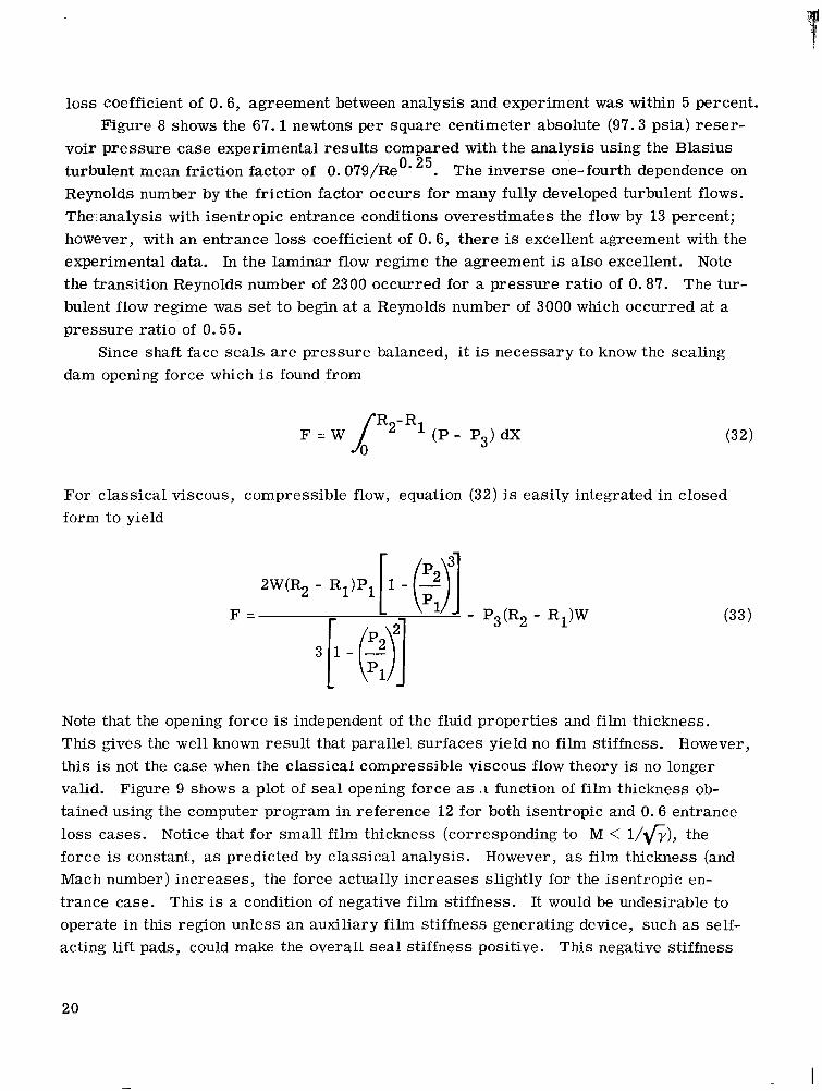
Since shaft face seals are pressure balanced, it is necessary to know the sealing dam opening force which is found from
F = W p-R1 (P - P3) dX
For classical viscous, compressible flow, equation (32) is easily integrated in closed form to yield
F = (33)
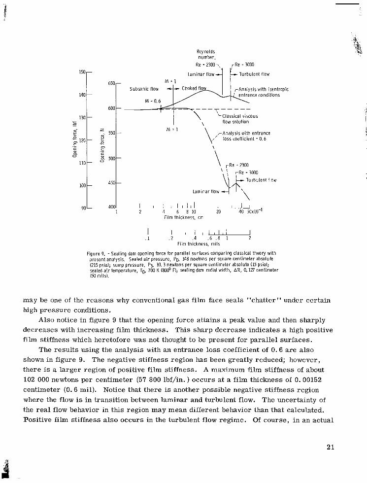
Note that the opening force is independent of the fluid properties and film thickness. This gives the well known result that parallel surfaces yield no film stiffness. this is not the case when the classical compressible viscous flow theory is no longer valid. Figure 9 shows a plot of sea l opening force as t t function of film thickness ob- tained using the computer program in reference 12 for both isentropic and 0.6 entrance loss cases. Notice that for small film thickness (corresponding to M < l/<y), the force is constant, as predicted by classical analysis. However, as film thickness (and Mach number) increases, the force actually increases slightly for the isentropic en- trance case. This is a condition of negative film stiffness. It would be undesirable to operate in this region unless an auxiliary film stiffness generating device, such as self- acting l i f t pads, could make the overall sea l stiffness positive. This negative stiffness
However,
20
150 r 650
600
550
500
450
140 t -
-
-
-
-
z W
cn 120 01 c c
lr
lr W
.- .- W a
look
Reynolds number,
Re = 2300-\ rRe = 3000
Laminar flow T u r b u l e n t flow
Subson ic flow rAna lys is w i t h isentropic
M = 0.6
-----?-- --- LClassical viscous
flow so lu t ion \
,-Analysis w i t h en t rance / loss coeff icient = 0.6
\
M - 1
rRe = 2300 = 3OOO T u r b u l e n t flow
\
\ Laminar f low
I I I 1 1 I l l 1 I L 2 4 6 8 1 0 20 40 5 0 ~ 1 0 . ~
L 4001 1
90
Film thickness, cm
I I l l - . 2 . 4 .6 . 8 1 2
I .1
F i lm thickness, m i l s
F igure 9. - S e a l i n g dam open ing force for paral lel surfaces comparing classical theory w i t h p resent analysis. Sealed a i r pressure, Po, 148 newtons p e r square cent imeter absolute (215 psia); sump pressure , P3, 10.3 newtons p e r square cent imeter absolute (15 psia); sealed a i r temperature, TO, 700 K (8@ F); seal ing dam radial width, AR, 0.127 cent imeter (50 mils).
may be one of the reasons why conventional gas film face seals "chatter" under certain high pressure conditions.
decreases with increasing film thickness. This sharp decrease indicates a high positive f i l m stiffness which heretofore was not thought t o be present for parallel surfaces.
The results using the analysis with an entrance loss coefficient of 0 .6 a r e also shown in figure 9. The negative stiffness region has been greatly reduced; however, there is a larger region of positive film stiffness. A maximum film stiffness of about 102 000 newtons per centimeter (57 800 lbf/in. ) occurs at a f i l m thickness of 0.00152 centimeter (0.6 mil). Notice that there is another possible negative stiffness region where the flow is in transition between laminar and turbulent flow. The uncertainty of the real flow behavior in this region may mean different behavior than that calculated. Positive f i l m stiffness also occurs in the turbulent flow regime. Of course, in an actual
Also notice in figure 9 that the opening force attains a peak value and then sharply
21

sea l design, the advantage gained by this added f i l m stiffness must be weighed against the higher leakage flow resulting from choked flow operation.
Limitat ions of t h e Analysis
One of the limitations of this analysis is the neglect of the details of the flow in the entrance length. tirely. This is reasonable for the slow viscous flows which characterize lubrication flows. However, when the flow becomes choked, the entrance velocities a r e high and it is possible that this neglect is improper.
The model developed herein may still be applied with good accuracy in cases where entrance effects a r e significant by using an entrance loss coefficient (see eqs. (25) to (27) and appendix C). Fleming and Sparrow have shown in reference 16 the bulk of the entrance losses occur in a small region very close to the duct inlet. Laminar incom- pressible entrance loss coefficients have been calculated and measured for a variety of duct shapes (e. g. , refs . 16 and 17). Turbulent loss coefficients a r e not s o widely re - ported; however, they may be calculated for parallel plate channels from the information in reference 18. The values for head loss coefficients k ' a r e generally less than 20 percent of those for laminar flow. Incompressible loss coefficients may be adequate for use with compressible flow (see appendix C).
with experiments. Also, calculations can be made very rapidly on a digital computer.
It is common in lubrication theory to neglect the entrance region en-
The use of the quasi- one- dimensional model can be justified by the good agreement
Seal Design Example
NASA has designed a sea l with self-acting l i f t pads for potential use as a mainshaft sea l in advanced gas turbine engines. This seal is described in references 4, 5, and 19. The sealing dam portion of this mainshaft face seal was designed and studied using the analysis presented herein.
Figure 10 shows the effect of sealing dam radial width on leakage flow f i l m thick- nesses from 2.5 to 0.25 micrometer (0.1 to 1 mil). The four radial dam widths used in the study were 0.051, 0. 127, and 0.254 centimeter (5, 20, 50, and 100 mils). These plots illustrate that, from strictly a leakage point of view, the longest leakage path pos- sible is most desirable. However, it is shown in reference 5 that the leakage path length must be compromised from a force balance point of view when surface deformations occur. Also shown in figure 10 is the leakage flow ra te - film thickness relation for a 0.001 centimeter (0.4 mil) sealing dam radial width. Notice that at film thicknesses
22

Sealing dam radial width.
. 4 m c Y U ._ 5 -'i
.1 .'t E - ._ U
AR, cm (mi l )
I 0.0127 (5) I /////
1 I 1 I I I I I I I I 1 1 1 I 1 1 1 I U . 2 . 4 . 6 . 8 1 2 4 6 8 1 0 20 40 60
I . 1
Leakage flow rate, std f t3/min
F igure 10. - Effect of seal face radial width o n seal leakage. Sealed a i r pressure, Po, 148 newtons p e r square cent imeter absolute (215 psia); sump pressure , P3. 10. 3 newtons p e r square cent imeter absolute (15 psial; sealed gas temperature, 700 K l80@ FI; paral lel sealing faces,
greater than 0.00063 centimeter (0.25 mil) the leakage coincides with the leakage values obtained for a knife edge using the theoretical orifice flow equation. Also notice the linear variation of leakage flow with f i l m thickness increase. dam width case when flow behaves as knife edge flow, the velocity entrance loss coeffi- cient is the same as the flow discharge coefficient used in orifice flow analysis.
0.0001 centimeter (0 .4 mil) and varying sealing dam width. Notice the knife edge, as expected, has the largest leakage flow rate. the theoretical orifice flow equation. The computer program resul t for a sealing dam width of 0.0001 centimeter (0.4 mil) agreed with the theoretical orifice flow equation. As the sealing dam width increases, the cri t ical pressure ratio for choking decreases as indicated by the sonic line in figure 11. Again the advantage of wider (longer) sealing dams is apparent.
Recent NASA sponsored tests (ref. 19) of a shaft face seal with self-acting lift aug- mentation have demonstrated the feasibility of operation at gas temperatures up to 910 K (1200' F), pressure differentials across the seal up to 172 newtons per square centime- ter (250 psi), and relative surface speeds up to 130 meters per second (450 ft/sec). These tests simulated the engine operating conditions such as takeoff, climb, cruise, and descent. The seal appears to be operating as predicted by the design analysis. Figure 12 shows the nosepiece seal assembly after the 120-hour endurance test.
For this narrow sealing
Figure 11 shows mass leakage flow as a function of pressure ratio for a fixed gap of
These values have been calculated from
Fig-
'AI
23

-I Choked flow -1 Subson ic 7- flow
VI .4 VI
2 I t n L
c .- E x . . 0,
3- 0 - L
W 0, m . Y m W -
v 0 . 2 .4 .6 .8 1.0
Pressure ratio, P3/Po
F igure 11. - M a s s leakage as f u n c t i o n of p r e s s u r e rat io f o r v a r i - ous seal ing dam radial w id ths AR. Sealed a i r p ressure , Pg. 148 newtons per square cent imeter absolute (215 psia); sealed gas temperature, 700 K (800’ F); f i lm th ickness , h, 0.00102 cent imeter (0.4 mil ) ; en t rance radial width, R1, 8.293cent i - meter (3.265 in. ).
r S e e fig. 13 /I\/’
-Seal ing dam
F igure 12. - Gas-film seal assembly nosepiece after 120-hour endurance test.
24

,Carbon r i n g
F igure 13. - Closeup of carbon nosepiece of gas-f i lm seal after 200 h o u r s of endurance testing. Total t ime on seal, 338.5 hours .
ure 13 shows a closeup of the carbon nosepiece from the shaft face seal with self-acting lift pads after 320 hours of steady-state endurance testing. The total time of testing on the carbon nosepiece was 338.5 hours. The pretesting lapping marks a r e still observ- able. A surface profile trace indicated that the average wear on the surface was less than 0.13 micrometer (5 pin. ). A few shallow scratches (1 to 2 pm, 50 to 100 pin. ) were noticed, The test was concluded after 500 total hours of carbon nosepiece opera- tion. The seal faces had encountered over 50 startups and shutdowns. The leakage ra tes varied from 5 . 1 9 ~ 1 0 - ~ to 1 5 . 6 ~ 1 0 ~ ~ standard cubic meter per second (11 to 32 s td
3 f t /min) with leakage generally averaging about 1. 18X10-3 standard cubic meter per second (25 std f t ' /min). 3 These leakage rates were close to those theoretically predicted.
SUMMARY OF RESULTS
An analysis has been presented for compressible fluid flow across shaft face seals. This quasi- one-dimensional integral analysis includes fluid inertia and entrance losses in addition to viscous friction which is accounted for by a mean friction factor. and choked flow conditions can be predicted and analyzed. The model is valid for both laminar and turbulent flows. The following pertinent resul ts were found:
Mach numbers less than l/<y. Excellent agreement with experiment is achieved i f an entrance velocity loss coefficient of 0.6 is used in the laminar flow regime. friction factor of 0.079/Re1/4 in the analysis yielded good experimental agreement in the turbulent flow regime.
Subsonic
1. Results agree with the classical subsonic compressible viscous flow theory for
The Blasius
25

2. Near and at cri t ical flow conditions (Mach number = 1) the isentropic entrance flow analysis shows a negative film stiffness; whereas for choked flow the analysis pre- dicts. a high positive film stiffness. The analysis with an entrance loss coefficient of 0.6 predicts a high positive film stiffness for choked flow and yielded a maximum posi- tive-film stiffness of 102 000 newtons per centimeter (57 800 lbf/in. ) for a design prob- lemstudied. The choked flow resul ts contrast to classical compressible viscous flow resul ts which show no film stiffness for parallel surfaces.
Lewis Research Center, National Aeronautics and Space Administration,
Cleveland, Ohio, January 19, 1972, 132- 15.
26

APPENDIX A
SYMBOLS
A
B
cL
cP D
e
F
f
f
h
i
k'
-
L1 M
M
P
Q r
AR
a3
Re
T
U
W
X
Z
gap cross- sectional area
friction parameter, 4T L/D
velocity entrance loss coefficient
specific heat at constant pressure
hydraulic diameter, 2h
specific internal energy
sealing dam force
Fanning friction factor, 7,/(pu2/2)
mean Fanning friction factor
film thickness (gap)
specific enthalpy
head loss coefficient
flow length from entrance to point of choking
Mach number, u/d-
mass flow
pres sur e
volume leakage flow rate
radius
sealing dam radial width (physical flow length), R2 - R1
gas constant = universal gas constant/molecular weight
Reynolds number, pu2h/p
temperature
average velocity
flow width
radial coordinate direction
coordinate across film thickness
27

-- - 1
p absolute (dynamic) viscosity
y specific heat ratio
p density
r shear stress
Subscripts:
N
w wetted surface
0 sealed (reservoir) conditions
1 entrance conditions
2 exit conditions
3 ambient sump conditions
Supers cript :
location along flow leakage length
- average value
28

APPENDIX B
FRICTION FACTOR - MACH NUMBER RELATION
Equation (9) may be derived in the following way. From the equation of state (eq. (7)) and the energy equation (eq. (5)) one obtains
Combining this with the mass conservation equation (eq. (2)) gives
2 2 dP - 1 + (7 - l)M du 2
U P 2
Combining equation (B2) with the momentum equation (eq. (8)) yields
2 From the definition of the Mach number (M2 = u /yaT) and the energy equation, one obtains
fl + y - 1 M2\ - du2 - -- dM2
\ 2 / u 2 M2
Equations (B3) and (B4) then give
2yM 2 f (1- M2) dM2 D 2 1+- ( y - l ) M I T = ' [ 2
29

from which equation (9) can be obtained; that is,
4f (1 - M2) dM2 -a= D YM '( 1 + - 'i M2)
30

APPENDIX C
REMARK ON LOSS COEFFICIENT
There are several effects which cause nonisentropic pressure drops in the face seal entrance region. Because of an abrupt geometric change at the seal passage entrance, there is a nonuniform profile caused by flow turning, separated flow, and "vena con- tracts" effect which results in an entrance pressure drop. The pressure drop in the flow-development length is higher than that in the fully developed flow region because of two effects (ref. 16). The first effect is higher wall shear caused by higher transverse velocity gradients. The second effect is the momentum increase as the velocity distri- bution becomes less uniform.
The role of the entrance velocity loss coefficient may be better understood by con- a, ! t sidering the incompressible Bernoulli equation relating the stagnation reservoir pres-
sure with the static and dynamic pressure at the seal entrance:
The actual velocity at the seal entrance is less than ideal; it can be expressed as
where CL is the entrance velocity loss coefficient (see ref. 20). Substitution of equa- tion (C2) in ( C l ) and use of the Mach number definition yield
2 YP,M. ' I 1 Po = P1 + n
or
P1 =
YM:: 1 +-
(C3 I
2c;
31

A binomial expansion of the denominator of the compressible entrance pressure equation (26) yields
The first two t e rms on the right side strongly predominate for Mach numbers less than unity. For example, when M/CL = 1 and y = 1.4,
1) = 1 + 0 . 7 0 + 0 . 1 8 + 0 . 0 2 + - *
The e r r o r is less than 11 percent i f only the first two t e rms are used. The accuracy would be greater at lower Mach numbers. The first two t e rms of the expansion are the same as the denominator of the Bernoulli equation (C4) for a gas behaving as a quasi- incompressible fluid. Using this observation the relation between the entrance velocity loss coefficient CL and head loss coefficient k' commonly used in hydraulics can be found. The incompressible Bernoulli equation with a head loss coefficient is
2 2
+ p1 Po - k'- p'l - -- PIUl
2 2
or
2 P1 = Po - (k'+ 1)- PIUl
2
Comparing equation (C7) with equation (C3) yields
32

This relation enables one to convert head loss coefficients reported in the literature to velocity loss coefficients CL, which are more convenient to use in Mach number "'i
relations.

APPENDIX D
DER I VAT I ON AN D J U ST I FI CAT I 0 N
Derivation of Mean Fanning Friction Factor
The mean Fanning friction factor commonly used in fluid mechanics is defined as
The classical viscous radial velocity distribution is (ref. 11)
u =-- dP (z2 - hz) 2P dx
The mean radial velocity is found from
o r
Since D = 2h, the mean Fanning friction factor becomes
- 24 f =- Re
Note the Fanning friction factor is one-fourth the Darcy-Weisbach friction factor which is commonly used in hydraulics. (In the text the velocity u is understood to be the mean velocity. )
34

Validity of Mean Fr ict ion Factor Evaluation Using Entrance Reynolds Number gl L
The question arises i f it is proper to use the entrance Reynolds number to evaluate the mean friction factor. Examining the Reynolds number,
pu2h Re =- P
or
2M constant WP P
Re =- =
Hence Re varies inversely with the absolute viscosity of the fluid which in turn var ies with the static temperature.
when M1 = 0 and M2 = 1. To see the maximum possible change, the maximum temperature possible occurs
Thus, the exit-entrance temperature ra t io can be found using equation (19) and is
For y = 1.4, T2/T1 = 5/6. This represents about a 17 percent variation in the static temperature for the worst case. From Sutherland's law
Hence, the maximum viscosity change along the seal leakage path will be small, and the entrance conditions can be used satisfactorily to evaluate the mean friction factor.
35

REFERENCES
1. Parks, A. J.; McKibbin, A. H.; Ng, C. C. W . ; and Slayton, R. M.: Development of Mainshaft Seals f o r Advanced Air Breathing Propulsion Systems. Rep. PWA- 3161, Pratt & Whitney Aircraft (NASA CR-72338), Aug. 14, 1967.
2. Shevchenko, Richard P. : Shaft, Bearing and Seal Systems f o r a Small Engine. Paper 670064, SAE, Jan. 1967.
3. McKibbin, A. H.; and Parks, A. J. : Aircraft Gas Turbine Mainshaft Face Seals- Problems and Promises. Fourth International Conference on Fluid Sealing. Special Publication SP-2, ASLE, 1969, paper FICFS-28.
4. Johnson, R. L . ; and Ludwig, L . P. : Shaft Face Seal With Self-Acting Lift Aug- mentation for Advanced Gas Turbine Engines. Fourth International Conference on Fluid Sealing. Special Publication SP-2, ASLE, 1969, paper FICFS-27.
5. Ludwig, L . P. ; Zuk, J. ; and Johnson, R. L . : Use of the Computer in Design of Gas Turbine Mainshaft Seals for Operation to 500 ft/sec (122 m/sec). Presented at 26th Annual Meeting of the National Conference on Fluid Power and the 10th Annual Meeting of the Fluid Power Society, Chicago, Ill., Oct. 13-15, 1970.
6 . Gross, William A. : Gas Film Lubrication. John Wiley & Sons, Inc. , 1962.
7. Carothers, P. R., Jr. : An Experimental Investigation of the Pressure Distribution of Air in Radial Flow in Thin Fi lms Between Parallel Plates. MS. Thesis, U.S. Navia l Post Grad. School, Monterey, Calif., 1961.
8. Grinnell, S. K. : Flow of a Compressible Fluid in a Thin Passage. Trans. ASME, vol. 78, no. 4, May 1956, pp. 765-771.
9. Mueller, Heinz K. : Self Aligning Radial Clearance Seals. Third International Con- ference cn Fluid Sealing, British Hydromechanics Research Assoc. , Cambridge, Eng., Apr. 3-5, 1967, paper H6.
10. Mayer, E. (B.S. Nau, t rans . ) : Mechanical Seals. American Elsevier, 1970.
11. Zuk, John; and Smith, Patricia J. : Computer Program for Viscous, Isothermal Compressible Flow Across a Sealing Dam with Small Tilt Angle. NASA TN D- 5373, 1969.
12. Zuk, J. ; and Smith, P. J. : Quasi-One-Dimensional Compressible Flow Across Face Seals and Narrow Slots. I1 - Computer Program. NASA TN D-6787, 1972
36

13. Zuk, John; and Ludwig, Lawrence P. : Investigation of Isothermal, Compressible Flow Across a Rotating Sealing Dam. I - Analysis. NASA TN D-5344, 1969.
14. Egli, Adolf: The Leakage of Gases Through Narrow Channels. J. Appl. Mech., vol. 4, no. 2, June 1937, pp. A-63 - A-67.
15. Shapiro, Ascher H. : The Dynamics and Thermodynamics of Compressible Fluid Flow. Vol. I. Ronald Press Co., 1953.
16. Fleming, David P. ; and Sparrow, E . M. : Flow in the Hydrodynamic Entrance Region of Ducts of Arbitrary Cross Section. J . Heat Transfer, vol. 91, no. 3, Aug. 1969, pp. 345-354.
17. Lundgren, T. S . ; Sparrow, E . M.; and Starr , J. B.: P re s su re Drop Due to the Entrance Region in Ducts of Arbitrary Cross Section. J. Basic Eng., vol. 86, no. 3, Sept. 1964, pp. 620-626.
18. Deissler, Robert G. : Analysis of Turbulent Heat Transfer and Flow in the Entrance Regions of Smooth Passages. NACA TN 3016, 1953.
19. Povinelli, V. P. ; and McKibbin, A. H . : Development of Mainshaft Seals for Advanced Air Breathing Propulsion Systems, Phase 11. Rep. PWA-3933, Pratt & Whitney Aircraft (NASA CR-72737), June 23, 1970.
20. Sabersky, Rolf H. ; and Acosta, A. J.: Fluid Flow. Macmillan Co., 1964.
NASA-Langley, 1972 - 15 E-6819

N A T I 0 N A ISA E R 0 N A u T I CS AN D s PAC E A D M I ST RAT I o N W A S H I N G T O N , D.C. 20546
POSTAGE AND FEES PAID NATIONAL AERONAUTICS AND
SPACE ADMINISTRATION
i i
FIRST CLASS MAIL USMAIL 0 FFI C I AL BUS I N E S S
PENALTY FOR PRIVATE USE $300
i
I
i (
/
016 002 C 1 U 15 720505 50090305 D E P T O F T H E A I R FORCE AF WEAPONS L A B I A F S C ) TECH L Z B R A R Y / W L O L / ATTN: E L O U HOWMANI C H I E F K I R T L A N O AFB N M 87117
POSTMASTER: If Undeliverable (Section 158 Portal Manual) Do Nor Return
"The aeronautical and space activities of the United States shall be conducted so as to contribute . . . to the expansion of human knowl- edge of phenoinena in the atmosphere and space. The Administration shall provide for the widest practicable and appropriate dissemination of information concerning its activities and the resiclts thereof!'
-NATIONAL AERONAUTICS AND SPACE ACT OF 1958
NASA SCIENTIFIC AND TECHNICAL PUBLICATIONS
TECHNICAL REPORTS: Scientific and technical information considered important, complete, and a lasting contribution to,existing knowledge.
TECHNICAL NOTES: Information less broad in scope but nevertheless of importance as a contribution to existing knowledge.
TECHNICAL MEMORANDUMS : Information receiving limited distribution because of preliminary data, security classifica- tion, or other reasons.
CONTRACTOR REPORTS: Scientific and technical information generated under a NASA contract or grant and considered an important contribution to existing knowledge.
TECHNICAL TRANSLATIONS: Information published in a foreign language considered to merit NASA distribution in English.
SPECIAL PUBLICATIONS: Information derived from or of value to NASA activities. Publications include conference proceedings, monographs, data compilations, handbooks, sourcebooks, and special bibliographies.
TECHNOLOGY UTILIZATION PUBLICATIONS: Information on technology used by NASA that may be of particular interest in commercial and other non-aerospace applications. Publications include Tech Briefs, Technology Utilization Reports and Technology Surveys.
Details on the availability of these publications may be obtained from:
SCIENTIFIC AND TECHNICAL INFORMATION OFFICE
NATlO NA L AER 0 N AUT1 C S AN D SPACE AD M IN I STRATI 0 N Washington, D.C. PO546