(question b1 continued)nothingnerdy.wikispaces.com/file/view/combined+ibhl...section a answer all...
TRANSCRIPT
(Question B1 continued)
Current electricity
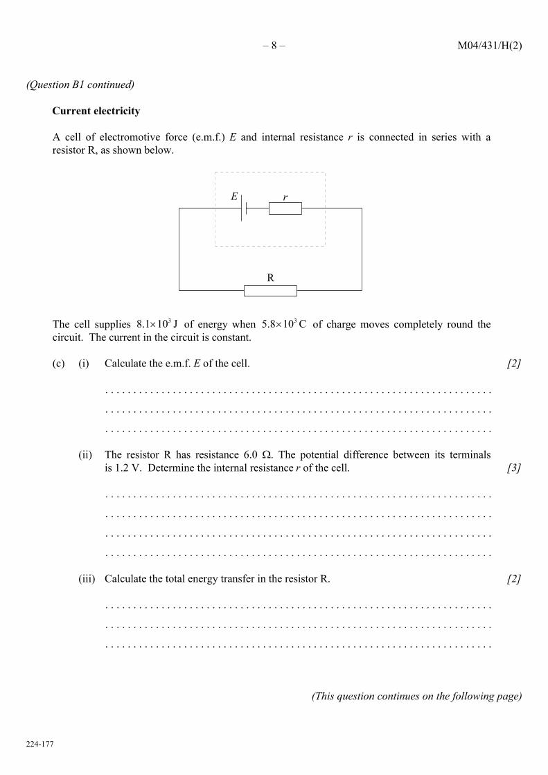
A cell of electromotive force (e.m.f.) E and internal resistance r is connected in series with aresistor R, as shown below.
R
rE
The cell supplies of energy when of charge moves completely round the38.1 10 J× 35.8 10 C×circuit. The current in the circuit is constant.
[2](c) (i) Calculate the e.m.f. E of the cell.
. . . . . . . . . . . . . . . . . . . . . . . . . . . . . . . . . . . . . . . . . . . . . . . . . . . . . . . . . . . . . . . . . . . . .
. . . . . . . . . . . . . . . . . . . . . . . . . . . . . . . . . . . . . . . . . . . . . . . . . . . . . . . . . . . . . . . . . . . . .
. . . . . . . . . . . . . . . . . . . . . . . . . . . . . . . . . . . . . . . . . . . . . . . . . . . . . . . . . . . . . . . . . . . . .
[3](ii) The resistor R has resistance 6.0 . The potential difference between its terminals
is 1.2 V. Determine the internal resistance r of the cell.
. . . . . . . . . . . . . . . . . . . . . . . . . . . . . . . . . . . . . . . . . . . . . . . . . . . . . . . . . . . . . . . . . . . . .
. . . . . . . . . . . . . . . . . . . . . . . . . . . . . . . . . . . . . . . . . . . . . . . . . . . . . . . . . . . . . . . . . . . . .
. . . . . . . . . . . . . . . . . . . . . . . . . . . . . . . . . . . . . . . . . . . . . . . . . . . . . . . . . . . . . . . . . . . . .
. . . . . . . . . . . . . . . . . . . . . . . . . . . . . . . . . . . . . . . . . . . . . . . . . . . . . . . . . . . . . . . . . . . . .
[2](iii) Calculate the total energy transfer in the resistor R.
. . . . . . . . . . . . . . . . . . . . . . . . . . . . . . . . . . . . . . . . . . . . . . . . . . . . . . . . . . . . . . . . . . . . .
. . . . . . . . . . . . . . . . . . . . . . . . . . . . . . . . . . . . . . . . . . . . . . . . . . . . . . . . . . . . . . . . . . . . .
. . . . . . . . . . . . . . . . . . . . . . . . . . . . . . . . . . . . . . . . . . . . . . . . . . . . . . . . . . . . . . . . . . . . .
(This question continues on the following page)
– 8 – M04/431/H(2)
224-177

(Question B1 continued)
[5](iv) Describe, in terms of a simple model of electrical conduction, the mechanism by which
the energy transfer in the resistor R takes place.
. . . . . . . . . . . . . . . . . . . . . . . . . . . . . . . . . . . . . . . . . . . . . . . . . . . . . . . . . . . . . . . . . . . . .
. . . . . . . . . . . . . . . . . . . . . . . . . . . . . . . . . . . . . . . . . . . . . . . . . . . . . . . . . . . . . . . . . . . . .
. . . . . . . . . . . . . . . . . . . . . . . . . . . . . . . . . . . . . . . . . . . . . . . . . . . . . . . . . . . . . . . . . . . . .
. . . . . . . . . . . . . . . . . . . . . . . . . . . . . . . . . . . . . . . . . . . . . . . . . . . . . . . . . . . . . . . . . . . . .
. . . . . . . . . . . . . . . . . . . . . . . . . . . . . . . . . . . . . . . . . . . . . . . . . . . . . . . . . . . . . . . . . . . . .
. . . . . . . . . . . . . . . . . . . . . . . . . . . . . . . . . . . . . . . . . . . . . . . . . . . . . . . . . . . . . . . . . . . . .
(This question continues on the following page)
– 9 – M04/431/H(2)
224-177 Turn over

SECTION A
Answer all the questions in the spaces provided.
A1. Data based question. This question is about change of electrical resistance with temperature.
The table below gives values of the resistance R of an electrical component for different values ofits temperature T. (Uncertainties in measurement are not shown.)
2650277028803060325034803590R/
9.68.16.85.23.52.01.2 / CT °
[3](a) On the grid below, plot a graph to show the variation with temperature T of the resistance R.
Show values on the temperature axis from T = to T = .0 C° 10 C°
(This question continues on the following page)
– 2 – M04/431/H(2)
224-177

(Question A1 continued)
[1](b) (i) Draw a curve that best fits the points you have plotted. Extend your curve to cover the
temperature range from to .0 C° 10 C°
[2](ii) Use your graph to determine the resistance at and at .0 C° 10 C°
Resistance at = . . . . . . . . . . . . . . . . . . . . . . .0 C°
Resistance at = . . . . . . . . . . . . . . . . . . . . . .10 C°
[1]
(c) On your graph, draw a straight-line between the resistance values at and at . This0 C° 10 C°line shows the variation with temperature (between and ) of the resistance,0 C° 10 C°assuming a linear change.
[1](d) (i) Assuming a linear change of resistance with temperature, use your graph to determine
the temperature at which the resistance is 3060 .
Temperature = . . . . . . . . . . . . . . . . . . . . . . . . . . C°
[3]
(ii) Use your answer in (d)(i) to calculate the percentage difference in the temperature for aresistance of 3060 that results from assuming a linear change rather than thenon-linear change.
. . . . . . . . . . . . . . . . . . . . . . . . . . . . . . . . . . . . . . . . . . . . . . . . . . . . . . . . . . . . . . . . . . . . .
. . . . . . . . . . . . . . . . . . . . . . . . . . . . . . . . . . . . . . . . . . . . . . . . . . . . . . . . . . . . . . . . . . . . .
. . . . . . . . . . . . . . . . . . . . . . . . . . . . . . . . . . . . . . . . . . . . . . . . . . . . . . . . . . . . . . . . . . . . .
(e) In a particular experiment to measure the variation with temperature of the resistance, eachmeasurement of resistance has an uncertainty of ! 30 and the uncertainty in the temperaturemeasurements is ! .0.2 C°
[2](i) On your graph in (a), show the uncertainties in the values of R and of T for
temperatures of .1.2 C, 5.2 C and 9.6 C° ° °
[2](ii) State and explain whether, within the experimental uncertainties, the relationship
between resistance and temperature could be linear.
. . . . . . . . . . . . . . . . . . . . . . . . . . . . . . . . . . . . . . . . . . . . . . . . . . . . . . . . . . . . . . . . . . . . .
. . . . . . . . . . . . . . . . . . . . . . . . . . . . . . . . . . . . . . . . . . . . . . . . . . . . . . . . . . . . . . . . . . . . .
. . . . . . . . . . . . . . . . . . . . . . . . . . . . . . . . . . . . . . . . . . . . . . . . . . . . . . . . . . . . . . . . . . . . .
– 3 – M04/431/H(2)
224-177 Turn over

A3. This question is about a filament lamp.
[1]
(a) On the axes below, draw a sketch-graph to show the variation with potential difference V ofthe current I in a typical filament lamp (the I–V characteristic). (Note: this is a sketch-graph;you do not need to add any values to the axes).
0 0
V
I
[1](b) (i) Explain how the resistance of the filament is determined from the graph.
. . . . . . . . . . . . . . . . . . . . . . . . . . . . . . . . . . . . . . . . . . . . . . . . . . . . . . . . . . . . . . . . . . . . .
. . . . . . . . . . . . . . . . . . . . . . . . . . . . . . . . . . . . . . . . . . . . . . . . . . . . . . . . . . . . . . . . . . . . .
[1](ii) Explain whether the graph you have sketched indicates ohmic behaviour or non-ohmic
behaviour.
. . . . . . . . . . . . . . . . . . . . . . . . . . . . . . . . . . . . . . . . . . . . . . . . . . . . . . . . . . . . . . . . . . . . .
. . . . . . . . . . . . . . . . . . . . . . . . . . . . . . . . . . . . . . . . . . . . . . . . . . . . . . . . . . . . . . . . . . . . .
A filament lamp operates at maximum brightness when connected to a 6.0 V supply. At maximumbrightness, the current in the filament is 120 mA.
[1](c) (i) Calculate the resistance of the filament when it is operating at maximum brightness.
. . . . . . . . . . . . . . . . . . . . . . . . . . . . . . . . . . . . . . . . . . . . . . . . . . . . . . . . . . . . . . . . . . . . .
[2]
(ii) You have available a 24 V supply and a collection of resistors of a suitable powerrating and with different values of resistance. Calculate the resistance of the resistorthat is required to be connected in series with the supply such that the voltage acrossthe filament lamp will be 6.0 V.
. . . . . . . . . . . . . . . . . . . . . . . . . . . . . . . . . . . . . . . . . . . . . . . . . . . . . . . . . . . . . . . . . . . . .
. . . . . . . . . . . . . . . . . . . . . . . . . . . . . . . . . . . . . . . . . . . . . . . . . . . . . . . . . . . . . . . . . . . . .
. . . . . . . . . . . . . . . . . . . . . . . . . . . . . . . . . . . . . . . . . . . . . . . . . . . . . . . . . . . . . . . . . . . . .
– 6 – M04/432/H(2)
224-180

2206-6508
– 14 – M06/4/PHYSI/HP2/ENG/TZ1/XX+
(Question B1 continued)
part 2 Heating water electrically
The diagram below shows part of the heating circuit of a domestic shower.
cold water 14°C
insulated wire
240Vwater pipe
supply
insulated heating elementhot water 40°C
Coldwaterenterstheshowerunitandflowsoveraninsulatedheatingelement.Theheatingelementisratedat7.2kW,240V.Thewaterentersatatemperatureof14°C and leaves at a temperature of 40°C.Thespecificheatcapacityofwateris4.2 103 J kg−1 K−1.
(a) Describe how thermal energy is transferred from the heating element to the water.
. . . . . . . . . . . . . . . . . . . . . . . . . . . . . . . . . . . . . . . . . . . . . . . . . . . . . . . . . . . . . . . . . . . . . . .
. . . . . . . . . . . . . . . . . . . . . . . . . . . . . . . . . . . . . . . . . . . . . . . . . . . . . . . . . . . . . . . . . . . . . . .
. . . . . . . . . . . . . . . . . . . . . . . . . . . . . . . . . . . . . . . . . . . . . . . . . . . . . . . . . . . . . . . . . . . . . . .
. . . . . . . . . . . . . . . . . . . . . . . . . . . . . . . . . . . . . . . . . . . . . . . . . . . . . . . . . . . . . . . . . . . . . . .
. . . . . . . . . . . . . . . . . . . . . . . . . . . . . . . . . . . . . . . . . . . . . . . . . . . . . . . . . . . . . . . . . . . . . . .
[3]
(b) Estimatetheflowrateinkgs−1 of the water.
. . . . . . . . . . . . . . . . . . . . . . . . . . . . . . . . . . . . . . . . . . . . . . . . . . . . . . . . . . . . . . . . . . . . . . .
. . . . . . . . . . . . . . . . . . . . . . . . . . . . . . . . . . . . . . . . . . . . . . . . . . . . . . . . . . . . . . . . . . . . . . .
. . . . . . . . . . . . . . . . . . . . . . . . . . . . . . . . . . . . . . . . . . . . . . . . . . . . . . . . . . . . . . . . . . . . . . .
. . . . . . . . . . . . . . . . . . . . . . . . . . . . . . . . . . . . . . . . . . . . . . . . . . . . . . . . . . . . . . . . . . . . . . .
. . . . . . . . . . . . . . . . . . . . . . . . . . . . . . . . . . . . . . . . . . . . . . . . . . . . . . . . . . . . . . . . . . . . . . .
. . . . . . . . . . . . . . . . . . . . . . . . . . . . . . . . . . . . . . . . . . . . . . . . . . . . . . . . . . . . . . . . . . . . . . .
[4]
(This question continues on the following page)
1436

2206-6508
– 15 –
turn over
M06/4/PHYSI/HP2/ENG/TZ1/XX+
(Question B1, part 2 continued)
(c) Suggest two reasons why your answer to (b) is only an estimate.
1. . . . . . . . . . . . . . . . . . . . . . . . . . . . . . . . . . . . . . . . . . . . . . . . . . . . . . . . . . . . . . . . . . .
. . . . . . . . . . . . . . . . . . . . . . . . . . . . . . . . . . . . . . . . . . . . . . . . . . . . . . . . . . . . . . . . . .
2. . . . . . . . . . . . . . . . . . . . . . . . . . . . . . . . . . . . . . . . . . . . . . . . . . . . . . . . . . . . . . . . . . .
. . . . . . . . . . . . . . . . . . . . . . . . . . . . . . . . . . . . . . . . . . . . . . . . . . . . . . . . . . . . . . . . . .
[2]
(d) Calculate the current in the heating element when the element is operating at 7.2 kW.
. . . . . . . . . . . . . . . . . . . . . . . . . . . . . . . . . . . . . . . . . . . . . . . . . . . . . . . . . . . . . . . . . . . . . . .
. . . . . . . . . . . . . . . . . . . . . . . . . . . . . . . . . . . . . . . . . . . . . . . . . . . . . . . . . . . . . . . . . . . . . . .
. . . . . . . . . . . . . . . . . . . . . . . . . . . . . . . . . . . . . . . . . . . . . . . . . . . . . . . . . . . . . . . . . . . . . . .
[2]
(e) Explain why, when the shower unit is switched on, the initial current in the heating element is greater than the current calculated in (d).
. . . . . . . . . . . . . . . . . . . . . . . . . . . . . . . . . . . . . . . . . . . . . . . . . . . . . . . . . . . . . . . . . . . . . . .
. . . . . . . . . . . . . . . . . . . . . . . . . . . . . . . . . . . . . . . . . . . . . . . . . . . . . . . . . . . . . . . . . . . . . . .
. . . . . . . . . . . . . . . . . . . . . . . . . . . . . . . . . . . . . . . . . . . . . . . . . . . . . . . . . . . . . . . . . . . . . . .
[2]
(This question continues on the following page)
1536

2206-6508
– 16 – M06/4/PHYSI/HP2/ENG/TZ1/XX+
(Question B1, part 2 continued)
(f) Insomecountries,showerunitsareoperatedfroma110Vsupply. Aheatingelementoperatingwitha240VsupplyhasresistanceR240andanelementoperatingfroma110Vsupply has resistance R110.
(i) Deduce, that for heating elements to have identical power outputs
RR
110
240
0 21= . .
. . . . . . . . . . . . . . . . . . . . . . . . . . . . . . . . . . . . . . . . . . . . . . . . . . . . . . . . . . . . . . . . . .
. . . . . . . . . . . . . . . . . . . . . . . . . . . . . . . . . . . . . . . . . . . . . . . . . . . . . . . . . . . . . . . . . .
. . . . . . . . . . . . . . . . . . . . . . . . . . . . . . . . . . . . . . . . . . . . . . . . . . . . . . . . . . . . . . . . . .
. . . . . . . . . . . . . . . . . . . . . . . . . . . . . . . . . . . . . . . . . . . . . . . . . . . . . . . . . . . . . . . . . .
. . . . . . . . . . . . . . . . . . . . . . . . . . . . . . . . . . . . . . . . . . . . . . . . . . . . . . . . . . . . . . . . . .
. . . . . . . . . . . . . . . . . . . . . . . . . . . . . . . . . . . . . . . . . . . . . . . . . . . . . . . . . . . . . . . . . .
. . . . . . . . . . . . . . . . . . . . . . . . . . . . . . . . . . . . . . . . . . . . . . . . . . . . . . . . . . . . . . . . . .
. . . . . . . . . . . . . . . . . . . . . . . . . . . . . . . . . . . . . . . . . . . . . . . . . . . . . . . . . . . . . . . . . .
[3]
(ii) Using the ratio in (i), describe and explain onedisadvantageofusinga110Vsupplyfor domestic purposes.
. . . . . . . . . . . . . . . . . . . . . . . . . . . . . . . . . . . . . . . . . . . . . . . . . . . . . . . . . . . . . . . . . .
. . . . . . . . . . . . . . . . . . . . . . . . . . . . . . . . . . . . . . . . . . . . . . . . . . . . . . . . . . . . . . . . . .
. . . . . . . . . . . . . . . . . . . . . . . . . . . . . . . . . . . . . . . . . . . . . . . . . . . . . . . . . . . . . . . . . .
. . . . . . . . . . . . . . . . . . . . . . . . . . . . . . . . . . . . . . . . . . . . . . . . . . . . . . . . . . . . . . . . . .
[2]
1636

2206-6508
– 8 – M06/4/PHYSI/HP2/ENG/TZ1/XX+
a3. This question is about an electric circuit.
Aparticularfilamentlampisratedat12V,6.0mA.Itjustlightswhenthepotentialdifferenceacrossthefilamentis6.0V.
A student sets up a electric circuit to measure the I-Vcharacteristicsofthefilamentlamp.
In the circuit, shown below, the student has connected the voltmeter and the ammeter into the circuit incorrectly.
12V
A
100 kΩ S
V
The battery has e.m.f. 12V and negligible internal resistance. The ammeter has negligibleresistance and the resistance of the voltmeter is 100 kΩ.
The maximum resistance of the variable resistor is 15 Ω.
(a) Explain, without doing any calculations, whether there is a position of the slider S at which the lamp will be lit.
. . . . . . . . . . . . . . . . . . . . . . . . . . . . . . . . . . . . . . . . . . . . . . . . . . . . . . . . . . . . . . . . . . . . . . .
. . . . . . . . . . . . . . . . . . . . . . . . . . . . . . . . . . . . . . . . . . . . . . . . . . . . . . . . . . . . . . . . . . . . . . .
. . . . . . . . . . . . . . . . . . . . . . . . . . . . . . . . . . . . . . . . . . . . . . . . . . . . . . . . . . . . . . . . . . . . . . .
. . . . . . . . . . . . . . . . . . . . . . . . . . . . . . . . . . . . . . . . . . . . . . . . . . . . . . . . . . . . . . . . . . . . . . .
. . . . . . . . . . . . . . . . . . . . . . . . . . . . . . . . . . . . . . . . . . . . . . . . . . . . . . . . . . . . . . . . . . . . . . .
[3]
(b) Estimate the maximum reading of the ammeter.
. . . . . . . . . . . . . . . . . . . . . . . . . . . . . . . . . . . . . . . . . . . . . . . . . . . . . . . . . . . . . . . . . . . . . . .
. . . . . . . . . . . . . . . . . . . . . . . . . . . . . . . . . . . . . . . . . . . . . . . . . . . . . . . . . . . . . . . . . . . . . . .
[2]
(This question continues on the following page)
0836

2206-6508
– 9 –
turn over
M06/4/PHYSI/HP2/ENG/TZ1/XX+
(Question A3 continued)
(c) Complete the circuit diagram below showing the correct position of the voltmeter and of the ammeter in order to determine the I-Vcharacteristicsofthefilamentlamp. [2]
12V
0936

2206-6514
– 21 –
turn over
M06/4/PHYSI/HP2/ENG/TZ2/XX+
b3. This question is about electric current and the effects of electric current.
Electric current
(a) The diagram below shows the circuit used to measure the current-voltage (I-V) characteristic of an electrical component X.
X
On the diagram above,
(i) label the ammeter A and the voltmeter V. [1]
(ii) mark the position of the contact of the potentiometer that will produce a reading of zero on the voltmeter. Label this position P. [1]
(This question continues on the following page)
2133

2206-6514
– 22 – M06/4/PHYSI/HP2/ENG/TZ2/XX+
(Question B3 continued)
(b) The graph below shows the current-voltage (I-V) characteristics of two different conductors X and Y.
I / A
0.50
0.45
0.40
0.35
0.30
0.25
0.20
0.15
0.10
0.05
0.00
Y X
0.0 1.0 2.0 3.0 4.0 5.0 6.0 7.0 8.0 9.0 10.0 11.0 12.0 13.0 14.0 15.0
V / V
(i) State the value of the current for which the resistance of X is the same as the resistance of Y and determine the value of this resistance.
Current: . . . . . . . . . . . . . . . . . . . . . . . . . . . . . . . . . . . . . . . . . . . . . . . . . . . . . . . .
Resistance: . . . . . . . . . . . . . . . . . . . . . . . . . . . . . . . . . . . . . . . . . . . . . . . . . . . . . . . .
. . . . . . . . . . . . . . . . . . . . . . . . . . . . . . . . . . . . . . . . . . . . . . . . . . . . . . . .
[2]
(ii) Describe and suggest an explanation for the I-V characteristic of conductor Y.
. . . . . . . . . . . . . . . . . . . . . . . . . . . . . . . . . . . . . . . . . . . . . . . . . . . . . . . . . . . . . . . . . .
. . . . . . . . . . . . . . . . . . . . . . . . . . . . . . . . . . . . . . . . . . . . . . . . . . . . . . . . . . . . . . . . . .
. . . . . . . . . . . . . . . . . . . . . . . . . . . . . . . . . . . . . . . . . . . . . . . . . . . . . . . . . . . . . . . . . .
. . . . . . . . . . . . . . . . . . . . . . . . . . . . . . . . . . . . . . . . . . . . . . . . . . . . . . . . . . . . . . . . . .
. . . . . . . . . . . . . . . . . . . . . . . . . . . . . . . . . . . . . . . . . . . . . . . . . . . . . . . . . . . . . . . . . .
[3]
(This question continues on the following page)
2233

2206-6514
– 23 –
turn over
M06/4/PHYSI/HP2/ENG/TZ2/XX+
(Question B3 continued)
(c) The two conductors X and Y are connected in the circuit as shown below.
12 V
Z
X
Y
The cell has e.m.f. 12 V and negligible internal resistance. The resistor Z has resistance R and the potential difference across the conductors X and Y is 5.0 V.
(i) Use the graph in (b) to determine the total current in the circuit.
. . . . . . . . . . . . . . . . . . . . . . . . . . . . . . . . . . . . . . . . . . . . . . . . . . . . . . . . . . . . . . . . . .
. . . . . . . . . . . . . . . . . . . . . . . . . . . . . . . . . . . . . . . . . . . . . . . . . . . . . . . . . . . . . . . . . .
. . . . . . . . . . . . . . . . . . . . . . . . . . . . . . . . . . . . . . . . . . . . . . . . . . . . . . . . . . . . . . . . . .
[2]
(ii) Determine the resistance R of the resistor Z.
. . . . . . . . . . . . . . . . . . . . . . . . . . . . . . . . . . . . . . . . . . . . . . . . . . . . . . . . . . . . . . . . . .
. . . . . . . . . . . . . . . . . . . . . . . . . . . . . . . . . . . . . . . . . . . . . . . . . . . . . . . . . . . . . . . . . .
. . . . . . . . . . . . . . . . . . . . . . . . . . . . . . . . . . . . . . . . . . . . . . . . . . . . . . . . . . . . . . . . . .
. . . . . . . . . . . . . . . . . . . . . . . . . . . . . . . . . . . . . . . . . . . . . . . . . . . . . . . . . . . . . . . . . .
[2]
(iii) Determine the total resistance of the parallel combination of X and Y.
. . . . . . . . . . . . . . . . . . . . . . . . . . . . . . . . . . . . . . . . . . . . . . . . . . . . . . . . . . . . . . . . . .
. . . . . . . . . . . . . . . . . . . . . . . . . . . . . . . . . . . . . . . . . . . . . . . . . . . . . . . . . . . . . . . . . .
. . . . . . . . . . . . . . . . . . . . . . . . . . . . . . . . . . . . . . . . . . . . . . . . . . . . . . . . . . . . . . . . . .
. . . . . . . . . . . . . . . . . . . . . . . . . . . . . . . . . . . . . . . . . . . . . . . . . . . . . . . . . . . . . . . . . .
[2]
(This question continues on the following page)
2333

2207-6508
– 26 – M07/4/PHYSI/HP2/ENG/TZ1/XX+
b3. This question is in two parts. part 1 is about electrical conduction and part 2 is about thermodynamics.
part 1 Electrical conduction
In a copper wire the number of conduction electrons is equal to the number of copper atoms in the wire.
(a) State what is meant by conduction electrons.
. . . . . . . . . . . . . . . . . . . . . . . . . . . . . . . . . . . . . . . . . . . . . . . . . . . . . . . . . . . . . . . . . . . . . . .
. . . . . . . . . . . . . . . . . . . . . . . . . . . . . . . . . . . . . . . . . . . . . . . . . . . . . . . . . . . . . . . . . . . . . . .
[1]
(b) (i) The density of copper is 8.93 ×10³ kg m–3 and its molar mass is 64 g. Deduce that the number of moles of copper in a volume of 1.0 m3 is 1.4 × 10⁵.
. . . . . . . . . . . . . . . . . . . . . . . . . . . . . . . . . . . . . . . . . . . . . . . . . . . . . . . . . . . . . . . . . .
. . . . . . . . . . . . . . . . . . . . . . . . . . . . . . . . . . . . . . . . . . . . . . . . . . . . . . . . . . . . . . . . . .
. . . . . . . . . . . . . . . . . . . . . . . . . . . . . . . . . . . . . . . . . . . . . . . . . . . . . . . . . . . . . . . . . .
[2]
(ii) Estimate the number of conduction electrons in 1.0 m3 of copper.
. . . . . . . . . . . . . . . . . . . . . . . . . . . . . . . . . . . . . . . . . . . . . . . . . . . . . . . . . . . . . . . . . .
. . . . . . . . . . . . . . . . . . . . . . . . . . . . . . . . . . . . . . . . . . . . . . . . . . . . . . . . . . . . . . . . . .
[1]
(c) The diagram below shows some of the conduction electrons in a copper wire. The arrows represent the random velocities of some of the electrons.
Explain, by reference to the motion of the electrons, why there is no current in the wire.
. . . . . . . . . . . . . . . . . . . . . . . . . . . . . . . . . . . . . . . . . . . . . . . . . . . . . . . . . . . . . . . . . . . . . . .
. . . . . . . . . . . . . . . . . . . . . . . . . . . . . . . . . . . . . . . . . . . . . . . . . . . . . . . . . . . . . . . . . . . . . . .
[2]
(This question continues on the following page)
copper wire
2637

2207-6508
– 27 –
Turn over
M07/4/PHYSI/HP2/ENG/TZ1/XX+
(Question B3, part 1 continued)
(d) An electric field is established inside the copper wire directed as shown in the diagram below. The dots represent electrons. The random velocities of the electrons are not shown.
On the diagram below, draw an arrow to indicate the direction of the drift velocity of the electrons. [1]
(This question continues on the following page)
electricfield
copper wire
2737

2207-6508
– 28 – M07/4/PHYSI/HP2/ENG/TZ1/XX+
(Question B3, part 1 continued)
(e) A typical value for the electron drift velocity in a copper wire is 10–3 m s–1. In the circuit below, the length of the copper wire joining the negative terminal of the battery to the lamp is 0.50 m.
S
0.50 m
(i) The switch S is closed. Calculate the time it would take for an electron to move from the negative terminal of the battery to the lamp.
. . . . . . . . . . . . . . . . . . . . . . . . . . . . . . . . . . . . . . . . . . . . . . . . . . . . . . . . . . . . . . . . . .
[1]
(ii) The lamp lights in a time much less than that calculated in (e)(i). Explain this observation.
. . . . . . . . . . . . . . . . . . . . . . . . . . . . . . . . . . . . . . . . . . . . . . . . . . . . . . . . . . . . . . . . . .
. . . . . . . . . . . . . . . . . . . . . . . . . . . . . . . . . . . . . . . . . . . . . . . . . . . . . . . . . . . . . . . . . .
. . . . . . . . . . . . . . . . . . . . . . . . . . . . . . . . . . . . . . . . . . . . . . . . . . . . . . . . . . . . . . . . . .
. . . . . . . . . . . . . . . . . . . . . . . . . . . . . . . . . . . . . . . . . . . . . . . . . . . . . . . . . . . . . . . . . .
[2]
(iii) Discuss, in terms of the movement of the electrons, the energy transformations takingplaceinthefilamentofthelamp.
. . . . . . . . . . . . . . . . . . . . . . . . . . . . . . . . . . . . . . . . . . . . . . . . . . . . . . . . . . . . . . . . . .
. . . . . . . . . . . . . . . . . . . . . . . . . . . . . . . . . . . . . . . . . . . . . . . . . . . . . . . . . . . . . . . . . .
. . . . . . . . . . . . . . . . . . . . . . . . . . . . . . . . . . . . . . . . . . . . . . . . . . . . . . . . . . . . . . . . . .
. . . . . . . . . . . . . . . . . . . . . . . . . . . . . . . . . . . . . . . . . . . . . . . . . . . . . . . . . . . . . . . . . .
. . . . . . . . . . . . . . . . . . . . . . . . . . . . . . . . . . . . . . . . . . . . . . . . . . . . . . . . . . . . . . . . . .
. . . . . . . . . . . . . . . . . . . . . . . . . . . . . . . . . . . . . . . . . . . . . . . . . . . . . . . . . . . . . . . . . .
[4]
(This question continues on the following page)
2837

2207-6508
– 29 –
Turn over
M07/4/PHYSI/HP2/ENG/TZ1/XX+
(Question B3, part 1 continued)
(f) The diagram below shows part of a circuit that may be used to determine the current - potential difference (I-V) characteristics of a lamp.
An ammeter and a voltmeter are required. On the diagram above, draw symbols to show the correct positions of the ammeter and the voltmeter. [2]
(g) The I-V characteristics for one lamp are shown below.
I / A 0.50
0.40
0.30
0.20
0.10
0.00 0.00 0.20 0.40 0.60 0.80 1.00 1.20 1.40 1.60
V / V
(i) State a range of values of the current I for which the lamp may be considered to show ohmic behaviour.
. . . . . . . . . . . . . . . . . . . . . . . . . . . . . . . . . . . . . . . . . . . . . . . . . . . . . . . . . . . . . . . . . .
[1]
(ii) The potential difference across the lamp is 0.80 V. Calculate the resistance of the lamp at this potential difference.
. . . . . . . . . . . . . . . . . . . . . . . . . . . . . . . . . . . . . . . . . . . . . . . . . . . . . . . . . . . . . . . . . .
. . . . . . . . . . . . . . . . . . . . . . . . . . . . . . . . . . . . . . . . . . . . . . . . . . . . . . . . . . . . . . . . . .
[2]
(This question continues on the following page)
2937

2207-6514
– 6 – M07/4/PHYSI/HP2/ENG/TZ2/XX+
a2. This question is about electric circuits.
(a) Define e.m.f. and state Ohm’s law.
e.m.f.: . . . . . . . . . . . . . . . . . . . . . . . . . . . . . . . . . . . . . . . . . . . . . . . . . . . . . . . . . . .
. . . . . . . . . . . . . . . . . . . . . . . . . . . . . . . . . . . . . . . . . . . . . . . . . . . . . . . . . . .
Ohm’s law: . . . . . . . . . . . . . . . . . . . . . . . . . . . . . . . . . . . . . . . . . . . . . . . . . . . . . . . . . . .
. . . . . . . . . . . . . . . . . . . . . . . . . . . . . . . . . . . . . . . . . . . . . . . . . . . . . . . . . . .
[2]
(b) In the circuit below an electrical device (load) is connected in series with a cell of e.m.f. 2.5 V and internal resistance r. The current I in the circuit is 0.10 A.
I = 0.10 A
e.m.f. = 2.5 V
r
load
The power dissipated in the load is 0.23 W.
Calculate
(i) the total power of the cell.
. . . . . . . . . . . . . . . . . . . . . . . . . . . . . . . . . . . . . . . . . . . . . . . . . . . . . . . . . . . . . . . . . .
. . . . . . . . . . . . . . . . . . . . . . . . . . . . . . . . . . . . . . . . . . . . . . . . . . . . . . . . . . . . . . . . . .
[1]
(ii) the resistance of the load.
. . . . . . . . . . . . . . . . . . . . . . . . . . . . . . . . . . . . . . . . . . . . . . . . . . . . . . . . . . . . . . . . . .
. . . . . . . . . . . . . . . . . . . . . . . . . . . . . . . . . . . . . . . . . . . . . . . . . . . . . . . . . . . . . . . . . .
. . . . . . . . . . . . . . . . . . . . . . . . . . . . . . . . . . . . . . . . . . . . . . . . . . . . . . . . . . . . . . . . . .
. . . . . . . . . . . . . . . . . . . . . . . . . . . . . . . . . . . . . . . . . . . . . . . . . . . . . . . . . . . . . . . . . .
[2]
(iii) the internal resistance r of the cell.
. . . . . . . . . . . . . . . . . . . . . . . . . . . . . . . . . . . . . . . . . . . . . . . . . . . . . . . . . . . . . . . . . .
. . . . . . . . . . . . . . . . . . . . . . . . . . . . . . . . . . . . . . . . . . . . . . . . . . . . . . . . . . . . . . . . . .
. . . . . . . . . . . . . . . . . . . . . . . . . . . . . . . . . . . . . . . . . . . . . . . . . . . . . . . . . . . . . . . . . .
. . . . . . . . . . . . . . . . . . . . . . . . . . . . . . . . . . . . . . . . . . . . . . . . . . . . . . . . . . . . . . . . . .
[2]
(This question continues on the following page)
0634

2207-6514
– 7 –
turn over
M07/4/PHYSI/HP2/ENG/TZ2/XX+
(Question A2 continued)
(c) A second identical cell is connected into the circuit in (b) as shown below.
I = 0.15 A
load
The current in this circuit is 0.15 A. Deduce that the load is a non-ohmic device.
. . . . . . . . . . . . . . . . . . . . . . . . . . . . . . . . . . . . . . . . . . . . . . . . . . . . . . . . . . . . . . . . . . . . . . .
. . . . . . . . . . . . . . . . . . . . . . . . . . . . . . . . . . . . . . . . . . . . . . . . . . . . . . . . . . . . . . . . . . . . . . .
. . . . . . . . . . . . . . . . . . . . . . . . . . . . . . . . . . . . . . . . . . . . . . . . . . . . . . . . . . . . . . . . . . . . . . .
. . . . . . . . . . . . . . . . . . . . . . . . . . . . . . . . . . . . . . . . . . . . . . . . . . . . . . . . . . . . . . . . . . . . . . .
. . . . . . . . . . . . . . . . . . . . . . . . . . . . . . . . . . . . . . . . . . . . . . . . . . . . . . . . . . . . . . . . . . . . . . .
. . . . . . . . . . . . . . . . . . . . . . . . . . . . . . . . . . . . . . . . . . . . . . . . . . . . . . . . . . . . . . . . . . . . . . .
[4]
0734

2208-6508
–22– M08/4/PHYSI/HP2/ENG/TZ1/XX+
b3. Thisquestionisintwoparts.Part 1 is about aspects of electric fields and electric charge and Part 2isaboutthermodynamics.
Part 1 Fieldsandelectricchargeassociatedwithatoms
(a) Aprotonmaybeconsideredtobeapointcharge.Forsuchaproton
(i) sketch the electric field pattern. [2]
(ii) calculate the magnitude of the electric field strength at a distance of 5.0 10 m−11× fromtheproton.
. . . . . . . . . . . . . . . . . . . . . . . . . . . . . . . . . . . . . . . . . . . . . . . . . . . . . . . . . . . . . . . . . .
. . . . . . . . . . . . . . . . . . . . . . . . . . . . . . . . . . . . . . . . . . . . . . . . . . . . . . . . . . . . . . . . . .
. . . . . . . . . . . . . . . . . . . . . . . . . . . . . . . . . . . . . . . . . . . . . . . . . . . . . . . . . . . . . . . . . .
. . . . . . . . . . . . . . . . . . . . . . . . . . . . . . . . . . . . . . . . . . . . . . . . . . . . . . . . . . . . . . . . . .
[2]
(This question continues on the following page)
2233

2208-6508
–2–
turn over
M08/4/PHYSI/HP2/ENG/TZ1/XX+
(Question B3, part 1 continued)
(b) Inasimplemodelofthehydrogenatom,anelectronorbitstheproton.Bothelectronandprotonareregardedaspointcharges.Theorbitalradiusoftheelectronis5.0 10 m−11× .
(i) Usingyouranswerto(a)(ii)deducethatthemagnitudeoftheelectricforcebetweentheelectronandtheprotonis. 10 N.−8×
. . . . . . . . . . . . . . . . . . . . . . . . . . . . . . . . . . . . . . . . . . . . . . . . . . . . . . . . . . . . . . . . . .
[1]
(ii) Deducethatthekineticenergyoftheelectronis 2. 10 J.−18×
. . . . . . . . . . . . . . . . . . . . . . . . . . . . . . . . . . . . . . . . . . . . . . . . . . . . . . . . . . . . . . . . . .
. . . . . . . . . . . . . . . . . . . . . . . . . . . . . . . . . . . . . . . . . . . . . . . . . . . . . . . . . . . . . . . . . .
. . . . . . . . . . . . . . . . . . . . . . . . . . . . . . . . . . . . . . . . . . . . . . . . . . . . . . . . . . . . . . . . . .
. . . . . . . . . . . . . . . . . . . . . . . . . . . . . . . . . . . . . . . . . . . . . . . . . . . . . . . . . . . . . . . . . .
. . . . . . . . . . . . . . . . . . . . . . . . . . . . . . . . . . . . . . . . . . . . . . . . . . . . . . . . . . . . . . . . . .
[3]
(c) Theelectronin(b)alsohaselectrostaticpotentialenergy.
(i) Define electrostatic potentialatapoint.
. . . . . . . . . . . . . . . . . . . . . . . . . . . . . . . . . . . . . . . . . . . . . . . . . . . . . . . . . . . . . . . . . .
. . . . . . . . . . . . . . . . . . . . . . . . . . . . . . . . . . . . . . . . . . . . . . . . . . . . . . . . . . . . . . . . . .
. . . . . . . . . . . . . . . . . . . . . . . . . . . . . . . . . . . . . . . . . . . . . . . . . . . . . . . . . . . . . . . . . .
[2]
(ii) Calculatetheelectrostaticpotentialenergyofthiselectron.
. . . . . . . . . . . . . . . . . . . . . . . . . . . . . . . . . . . . . . . . . . . . . . . . . . . . . . . . . . . . . . . . . .
. . . . . . . . . . . . . . . . . . . . . . . . . . . . . . . . . . . . . . . . . . . . . . . . . . . . . . . . . . . . . . . . . .
. . . . . . . . . . . . . . . . . . . . . . . . . . . . . . . . . . . . . . . . . . . . . . . . . . . . . . . . . . . . . . . . . .
. . . . . . . . . . . . . . . . . . . . . . . . . . . . . . . . . . . . . . . . . . . . . . . . . . . . . . . . . . . . . . . . . .
[2]
(This question continues on the following page)
2333

2208-6508
–24– M08/4/PHYSI/HP2/ENG/TZ1/XX+
(Question B3 part 1 continued)
(d) Usingyouranswersin(b)(ii)and(c)(ii)determinetheenergyrequired,inelectronvolt,to completely remove the electron from the influence of the proton.
. . . . . . . . . . . . . . . . . . . . . . . . . . . . . . . . . . . . . . . . . . . . . . . . . . . . . . . . . . . . . . . . . . . . . . .
. . . . . . . . . . . . . . . . . . . . . . . . . . . . . . . . . . . . . . . . . . . . . . . . . . . . . . . . . . . . . . . . . . . . . . .
. . . . . . . . . . . . . . . . . . . . . . . . . . . . . . . . . . . . . . . . . . . . . . . . . . . . . . . . . . . . . . . . . . . . . . .
. . . . . . . . . . . . . . . . . . . . . . . . . . . . . . . . . . . . . . . . . . . . . . . . . . . . . . . . . . . . . . . . . . . . . . .
[2]
Fieldsandelectricchargeinconductors
(e) Define electromotive force(e.m.f.).
. . . . . . . . . . . . . . . . . . . . . . . . . . . . . . . . . . . . . . . . . . . . . . . . . . . . . . . . . . . . . . . . . . . . . . .
. . . . . . . . . . . . . . . . . . . . . . . . . . . . . . . . . . . . . . . . . . . . . . . . . . . . . . . . . . . . . . . . . . . . . . .
[1]
(f) A filament lamp is operating at normal brightness.
The potential difference across the lamp is 6.0 V. The current in the filament is 0.20 A. For the filament of this lamp, calculate
(i) theresistance.
. . . . . . . . . . . . . . . . . . . . . . . . . . . . . . . . . . . . . . . . . . . . . . . . . . . . . . . . . . . . . . . . . .
. . . . . . . . . . . . . . . . . . . . . . . . . . . . . . . . . . . . . . . . . . . . . . . . . . . . . . . . . . . . . . . . . .
[1]
(ii) thepowerdissipated.
. . . . . . . . . . . . . . . . . . . . . . . . . . . . . . . . . . . . . . . . . . . . . . . . . . . . . . . . . . . . . . . . . .
. . . . . . . . . . . . . . . . . . . . . . . . . . . . . . . . . . . . . . . . . . . . . . . . . . . . . . . . . . . . . . . . . .
[1]
(This question continues on the following page)
2433

2208-6508
–25–
turn over
M08/4/PHYSI/HP2/ENG/TZ1/XX+
(Question B3 part 1 continued)
(g) Thelampin(f)isconnectedinthecircuitbelow.Thelampisstilloperatingatnormalbrightness.
BR
ThebatteryBhasaninternalresistanceof5.0andtheresistanceRoftheresistoris15.
(i) CalculatethecurrentintheresistorR.
. . . . . . . . . . . . . . . . . . . . . . . . . . . . . . . . . . . . . . . . . . . . . . . . . . . . . . . . . . . . . . . . . .
. . . . . . . . . . . . . . . . . . . . . . . . . . . . . . . . . . . . . . . . . . . . . . . . . . . . . . . . . . . . . . . . . .
[1]
(ii) Determinethee.m.f.ofthebattery.
. . . . . . . . . . . . . . . . . . . . . . . . . . . . . . . . . . . . . . . . . . . . . . . . . . . . . . . . . . . . . . . . . .
. . . . . . . . . . . . . . . . . . . . . . . . . . . . . . . . . . . . . . . . . . . . . . . . . . . . . . . . . . . . . . . . . .
. . . . . . . . . . . . . . . . . . . . . . . . . . . . . . . . . . . . . . . . . . . . . . . . . . . . . . . . . . . . . . . . . .
. . . . . . . . . . . . . . . . . . . . . . . . . . . . . . . . . . . . . . . . . . . . . . . . . . . . . . . . . . . . . . . . . .
. . . . . . . . . . . . . . . . . . . . . . . . . . . . . . . . . . . . . . . . . . . . . . . . . . . . . . . . . . . . . . . . . .
. . . . . . . . . . . . . . . . . . . . . . . . . . . . . . . . . . . . . . . . . . . . . . . . . . . . . . . . . . . . . . . . . .
[4]
(This question continues on the following page)
2533

8805-6502
– 11 –
Turn over
N05/4/PHYSI/HP2/ENG/TZ0/XX+
SECTION B
This section consists of four questions: B1, B2, B3 and B4. Answer two questions.
B1. This question is in two parts. Part 1 is about electrical circuits and Part 2 is about the physics of cooling.
Part 1 Electrical circuits
Andrew is set the task of measuring the current-voltage (I-V) characteristics of a filament lamp. The following equipment and information are available.
InformationBattery e.m.f. = 3.0 V, negligible internal resistance
Filament lamp marked “3 V, 0.2 A”
Voltmeter resistance = 30 kΩ, reads values between 0.0 and 3.0 V
Ammeter resistance = 0.1 Ω, reads values between 0.0 and 0.5 A
Potentiometer resistance = 100 Ω
(a) For the filament lamp operating at normal brightness, calculate
(i) its resistance.
. . . . . . . . . . . . . . . . . . . . . . . . . . . . . . . . . . . . . . . . . . . . . . . . . . . . . . . . . . . . . . . . .
. . . . . . . . . . . . . . . . . . . . . . . . . . . . . . . . . . . . . . . . . . . . . . . . . . . . . . . . . . . . . . . . .
[1]
(ii) its power dissipation.
. . . . . . . . . . . . . . . . . . . . . . . . . . . . . . . . . . . . . . . . . . . . . . . . . . . . . . . . . . . . . . . . .
. . . . . . . . . . . . . . . . . . . . . . . . . . . . . . . . . . . . . . . . . . . . . . . . . . . . . . . . . . . . . . . . .
[1]
(This question continues on the following page)
1133

8805-6502
– 12 – N05/4/PHYSI/HP2/ENG/TZ0/XX+
(Question B1, part 1 continued)
Andrew sets up the following incorrect circuit.
V
A
(b) (i) Explain why the lamp will not light.
. . . . . . . . . . . . . . . . . . . . . . . . . . . . . . . . . . . . . . . . . . . . . . . . . . . . . . . . . . . . . . . . .
. . . . . . . . . . . . . . . . . . . . . . . . . . . . . . . . . . . . . . . . . . . . . . . . . . . . . . . . . . . . . . . . .
. . . . . . . . . . . . . . . . . . . . . . . . . . . . . . . . . . . . . . . . . . . . . . . . . . . . . . . . . . . . . . . . .
[2]
(ii) State the approximate reading on the voltmeter. Explain your answer.
. . . . . . . . . . . . . . . . . . . . . . . . . . . . . . . . . . . . . . . . . . . . . . . . . . . . . . . . . . . . . . . . .
. . . . . . . . . . . . . . . . . . . . . . . . . . . . . . . . . . . . . . . . . . . . . . . . . . . . . . . . . . . . . . . . .
. . . . . . . . . . . . . . . . . . . . . . . . . . . . . . . . . . . . . . . . . . . . . . . . . . . . . . . . . . . . . . . . .
[2]
(c) On the circuit diagram below, add circuit symbols to show the correct position of the ammeter and of the voltmeter in order to measure the I-V characteristics of the lamp. [2]
(This question continues on the following page)
1233

8805-6502
– 13 –
Turn over
N05/4/PHYSI/HP2/ENG/TZ0/XX+
(Question B1, part 1 continued)
(d) On the axes below draw a sketch graph to show the I-V characteristics for this filament lamp. [4]
I / A
0.3
0.2
0.1
0.0 0.0 1.0 2.0 3.0 4.0 V / V
(e) Explain the shape of the graph that you have drawn in (d).
. . . . . . . . . . . . . . . . . . . . . . . . . . . . . . . . . . . . . . . . . . . . . . . . . . . . . . . . . . . . . . . . . . . . . .
. . . . . . . . . . . . . . . . . . . . . . . . . . . . . . . . . . . . . . . . . . . . . . . . . . . . . . . . . . . . . . . . . . . . . .
. . . . . . . . . . . . . . . . . . . . . . . . . . . . . . . . . . . . . . . . . . . . . . . . . . . . . . . . . . . . . . . . . . . . . .
. . . . . . . . . . . . . . . . . . . . . . . . . . . . . . . . . . . . . . . . . . . . . . . . . . . . . . . . . . . . . . . . . . . . . .
[2]
(This question continues on the following page)
1333

8807-6502
– 8 – N07/4/PHYSI/HP2/ENG/TZ0/XX
a3. This question is about electrical circuits.
The graph below shows the I-V (current-voltage) characteristic of an electrical component T.
I / mA
150
100
50
0 0.0 2.0 4.0 6.0 8.0
V / V
(a) On the graph above, draw the I-V characteristic in the range V = 0 to V = 6.0V for a resistor R having a constant resistance of 40 Ω. [1]
(This question continues on the following page)
0833

8807-6502
– 9 –
turn over
N07/4/PHYSI/HP2/ENG/TZ0/XX
(Question A3 continued)
(b) The component T and the resistor R are connected in parallel as shown below.
T
A
R
40 Ω
B
When a battery of constant e.m.f. E and negligible internal resistance is connected between the terminals A and B, the current in the resistor R is 100 mA.
(i) Calculate the e.m.f. E of the battery.
. . . . . . . . . . . . . . . . . . . . . . . . . . . . . . . . . . . . . . . . . . . . . . . . . . . . . . . . . . . . . . . . . .
. . . . . . . . . . . . . . . . . . . . . . . . . . . . . . . . . . . . . . . . . . . . . . . . . . . . . . . . . . . . . . . . . .
[1]
(ii) Use the graph to determine the current in T.
. . . . . . . . . . . . . . . . . . . . . . . . . . . . . . . . . . . . . . . . . . . . . . . . . . . . . . . . . . . . . . . . . .
[1]
(iii) Calculate the power dissipation in T.
. . . . . . . . . . . . . . . . . . . . . . . . . . . . . . . . . . . . . . . . . . . . . . . . . . . . . . . . . . . . . . . . . .
. . . . . . . . . . . . . . . . . . . . . . . . . . . . . . . . . . . . . . . . . . . . . . . . . . . . . . . . . . . . . . . . . .
. . . . . . . . . . . . . . . . . . . . . . . . . . . . . . . . . . . . . . . . . . . . . . . . . . . . . . . . . . . . . . . . . .
[2]
(This question continues on the following page)
0933
8807-6502
– 10 – N07/4/PHYSI/HP2/ENG/TZ0/XX
(Question A3 continued)
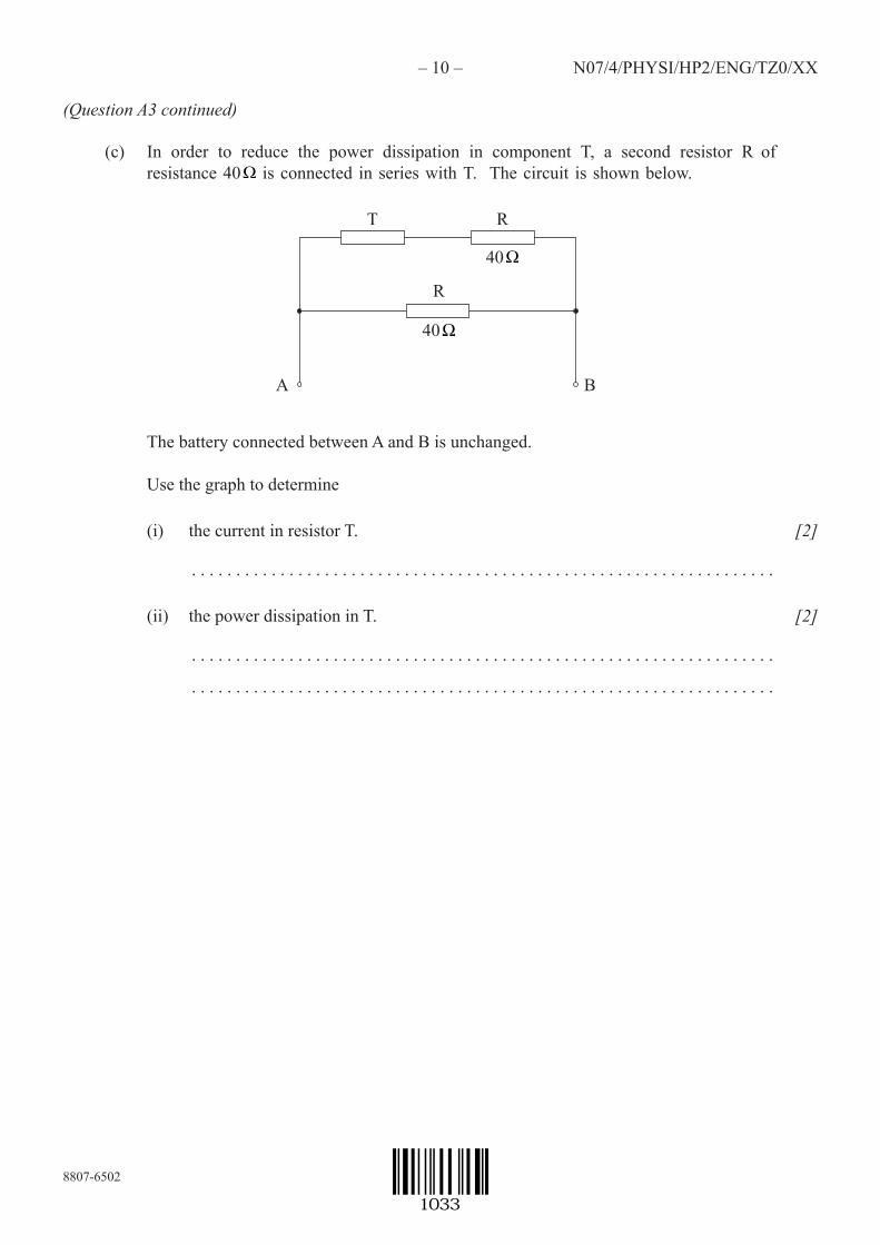
(c) In order to reduce the power dissipation in component T, a second resistor R of resistance 40 Ω is connected in series with T. The circuit is shown below.
T R
A
40 Ω
R
40 Ω
B
The battery connected between A and B is unchanged.
Use the graph to determine
(i) the current in resistor T.
. . . . . . . . . . . . . . . . . . . . . . . . . . . . . . . . . . . . . . . . . . . . . . . . . . . . . . . . . . . . . . . . . .
[2]
(ii) the power dissipation in T.
. . . . . . . . . . . . . . . . . . . . . . . . . . . . . . . . . . . . . . . . . . . . . . . . . . . . . . . . . . . . . . . . . .
. . . . . . . . . . . . . . . . . . . . . . . . . . . . . . . . . . . . . . . . . . . . . . . . . . . . . . . . . . . . . . . . . .
[2]
1033

8808-6502
–28– N08/4/PHYSI/HP2/ENG/TZ0/XX+
(Question B4 continued)
Part 2 Electricity
Staticelectricity
(a) A positively charged particle hangs from a vertical insulating string. The particle isbroughtaboveanelectricallyneutralmetallicspherethatrestsonaninsulatingsupport.
insulatingstring
positivelychargedparticle
metallicsphere
insulatingsupport
Byconsidering thedistributionofchargeon thesphere, stateandexplainwhether thetensionin thestringholdingthechargedparticlewillbe less than,equal toorgreaterthan theweightof theparticle.(Assumethatthemassofthestringisnegligible.)
. . . . . . . . . . . . . . . . . . . . . . . . . . . . . . . . . . . . . . . . . . . . . . . . . . . . . . . . . . . . . . . . . . . . . . .
. . . . . . . . . . . . . . . . . . . . . . . . . . . . . . . . . . . . . . . . . . . . . . . . . . . . . . . . . . . . . . . . . . . . . . .
. . . . . . . . . . . . . . . . . . . . . . . . . . . . . . . . . . . . . . . . . . . . . . . . . . . . . . . . . . . . . . . . . . . . . . .
. . . . . . . . . . . . . . . . . . . . . . . . . . . . . . . . . . . . . . . . . . . . . . . . . . . . . . . . . . . . . . . . . . . . . . .
[3]
(This question continues on the following page)
2831

8808-6502
–29–
turn over
N08/4/PHYSI/HP2/ENG/TZ0/XX+
(Question B4, part 2 continued)
(b) DiagramsA,BandCshowasequenceofeventsinwhich:A:thespherein(a)isearthed(grounded),•B:theearthisthenremovedwhilethechargedparticleremainsinplace,•C:finallythechargedparticleistakenaway.•
A B C
(i) OneachofthediagramsA,BandCdrawthedistributionofchargeonthesphere. [3]
(ii) Explain whywork hastobedone onthechargedparticletomove itaway fromthesphere.
. . . . . . . . . . . . . . . . . . . . . . . . . . . . . . . . . . . . . . . . . . . . . . . . . . . . . . . . . . . . . . . . . .
. . . . . . . . . . . . . . . . . . . . . . . . . . . . . . . . . . . . . . . . . . . . . . . . . . . . . . . . . . . . . . . . . .
[2]
(This question continues on the following page)
2931

8808-6502
–30– N08/4/PHYSI/HP2/ENG/TZ0/XX+
(Question B4, part 2 continued)
Currentelectricity
(c) Defineelectromotive force (e.m.f.).
. . . . . . . . . . . . . . . . . . . . . . . . . . . . . . . . . . . . . . . . . . . . . . . . . . . . . . . . . . . . . . . . . . . . . . .
. . . . . . . . . . . . . . . . . . . . . . . . . . . . . . . . . . . . . . . . . . . . . . . . . . . . . . . . . . . . . . . . . . . . . . .
[1]
(d) Inthecircuitbelowthebatteryhasane.m.f.of12Vandaninternalresistanceof5.0Ω.
e.m.f.=12V
60Ω 30Ω X
30Ω 60Ω
Y
Calculatethe
(i) totalresistanceofthecircuit.
. . . . . . . . . . . . . . . . . . . . . . . . . . . . . . . . . . . . . . . . . . . . . . . . . . . . . . . . . . . . . . . . . .
. . . . . . . . . . . . . . . . . . . . . . . . . . . . . . . . . . . . . . . . . . . . . . . . . . . . . . . . . . . . . . . . . .
. . . . . . . . . . . . . . . . . . . . . . . . . . . . . . . . . . . . . . . . . . . . . . . . . . . . . . . . . . . . . . . . . .
. . . . . . . . . . . . . . . . . . . . . . . . . . . . . . . . . . . . . . . . . . . . . . . . . . . . . . . . . . . . . . . . . .
[3]
(ii) currentintheinternalresistance.
. . . . . . . . . . . . . . . . . . . . . . . . . . . . . . . . . . . . . . . . . . . . . . . . . . . . . . . . . . . . . . . . . .
. . . . . . . . . . . . . . . . . . . . . . . . . . . . . . . . . . . . . . . . . . . . . . . . . . . . . . . . . . . . . . . . . .
[1]
(This question continues on the following page)
3031

8808-6502
–31– N08/4/PHYSI/HP2/ENG/TZ0/XX+
(Question B4, part 2 continued)
(iii) totalpowerdissipatedinthecircuit.
. . . . . . . . . . . . . . . . . . . . . . . . . . . . . . . . . . . . . . . . . . . . . . . . . . . . . . . . . . . . . . . . . .
. . . . . . . . . . . . . . . . . . . . . . . . . . . . . . . . . . . . . . . . . . . . . . . . . . . . . . . . . . . . . . . . . .
[2]
(iv) potentialdifferencebetweenpointsXandY.
. . . . . . . . . . . . . . . . . . . . . . . . . . . . . . . . . . . . . . . . . . . . . . . . . . . . . . . . . . . . . . . . . .
. . . . . . . . . . . . . . . . . . . . . . . . . . . . . . . . . . . . . . . . . . . . . . . . . . . . . . . . . . . . . . . . . .
. . . . . . . . . . . . . . . . . . . . . . . . . . . . . . . . . . . . . . . . . . . . . . . . . . . . . . . . . . . . . . . . . .
[3]
(e) Areal(i.e.non-ideal)voltmeterisconnectedacrosspointsXandYinthecircuitin(d).Explainwhythereadingofthisvoltmeterwillnotbethesameasyouranswerto(d)(iv).
. . . . . . . . . . . . . . . . . . . . . . . . . . . . . . . . . . . . . . . . . . . . . . . . . . . . . . . . . . . . . . . . . . . . . . .
. . . . . . . . . . . . . . . . . . . . . . . . . . . . . . . . . . . . . . . . . . . . . . . . . . . . . . . . . . . . . . . . . . . . . . .
[2]
3131