quick guide powerwalker vi (e)rt hid series 1000-3000 rt/powerwalker vi rt hid... · dry contacts...
TRANSCRIPT
ENGLISH
Quick Guide
PowerWalker VI (E)RT HID Series
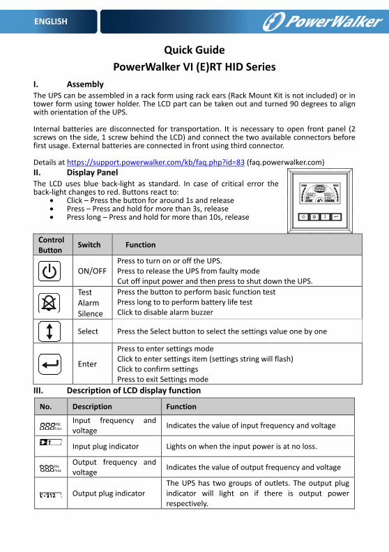
I. Assembly The UPS can be assembled in a rack form using rack ears (Rack Mount Kit is not included) or in tower form using tower holder. The LCD part can be taken out and turned 90 degrees to align with orientation of the UPS. Internal batteries are disconnected for transportation. It is necessary to open front panel (2 screws on the side, 1 screw behind the LCD) and connect the two available connectors before first usage. External batteries are connected in front using third connector. Details at https://support.powerwalker.com/kb/faq.php?id=83 (faq.powerwalker.com) II. Display Panel The LCD uses blue back-light as standard. In case of critical error the back-light changes to red. Buttons react to:
Click – Press the button for around 1s and release Press – Press and hold for more than 3s, release Press long – Press and hold for more than 10s, release
Control Button
Switch Function
ON/OFF
Press to turn on or off the UPS. Press to release the UPS from faulty mode Cut off input power and then press to shut down the UPS.
Test Alarm Silence
Press the button to perform basic function test Press long to to perform battery life test Click to disable alarm buzzer
Select Press the Select button to select the settings value one by one
Enter
Press to enter settings mode Click to enter settings item (settings string will flash) Click to confirm settings Press to exit Settings mode
III. Description of LCD display function
No. Description Function
Input frequency and voltage
Indicates the value of input frequency and voltage
Input plug indicator Lights on when the input power is at no loss.
Output frequency and voltage
Indicates the value of output frequency and voltage
Output plug indicator The UPS has two groups of outlets. The output plug indicator will light on if there is output power respectively.

ENGLISH
UPS status/user setting display String
Strings Indicate the UPS status( see Table 4) Strings Indicate user setting options( see Table 5)
Warning indication Lights on when the UPS is failure or alarm.
Settings Lights on when the UPS under settings mode.
Battery volume level display
Indicates the amount of battery volume remaining. Each battery volume level bar indicates approximately 20% of total battery volume
Load Power level display Indicates the load level of the UPS. Each level bar indicates approximately 20% of the total UPS output Power.
IV. Rear Panels
VI 1000 ERT
1. AC Output
2. Network Surge
Protection
3. Intelligent Slot
4. AC Input
5. RS232 / Dry-
Contact Port
6. USB Port
7. EPO
8. Grounding
VI 1000 RT and VI 1500 RT
VI 2000 RT
1. AC Output
2. Network Surge
Protection
3. Intelligent Slot
4. Fan
5. AC Input
6. RS232 / Dry-
Contact Port
87651
2 431
NE
TW
OR
K/T
ELE
PH
ON
EP
RO
TE
CT
ION
INP
UT
220
-24
0V
~
INTERFACE OPTION
EPOUSBRS232
OU
TIN
LS
2O
UT
PU
T
25
KV
~1
0A
LS
1O
UT
PU
T
25
KV
~1
0A
LS1OUTPUT
25KV~10A
LS2OUTPUT
25KV~10A
1 4
1
3
7
5
6 8 9
2
IN
OUT
NETWORK/TELEPHONEPROTECTION
INTERFACE OPTION
EPOUSBRS232 I
NPUT220-240V~
ENGLISH
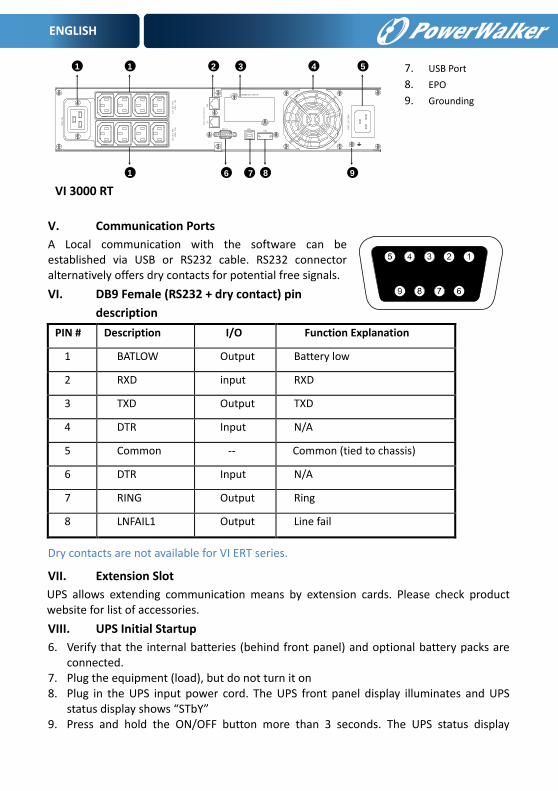
VI 3000 RT
7. USB Port
8. EPO
9. Grounding
V. Communication Ports
A Local communication with the software can be established via USB or RS232 cable. RS232 connector alternatively offers dry contacts for potential free signals.
VI. DB9 Female (RS232 + dry contact) pin
description
PIN # Description I/O Function Explanation
1 BATLOW Output Battery low
2 RXD input RXD
3 TXD Output TXD
4 DTR Input N/A
5 Common -- Common (tied to chassis)
6 DTR Input N/A
7 RING Output Ring
8 LNFAIL1 Output Line fail
Dry contacts are not available for VI ERT series.
VII. Extension Slot
UPS allows extending communication means by extension cards. Please check product website for list of accessories.
VIII. UPS Initial Startup
6. Verify that the internal batteries (behind front panel) and optional battery packs are connected.
7. Plug the equipment (load), but do not turn it on 8. Plug in the UPS input power cord. The UPS front panel display illuminates and UPS
status display shows “STbY” 9. Press and hold the ON/OFF button more than 3 seconds. The UPS status display
LS1OUTPUT
25KV~10A
LS2OUTPUT
25KV~10A
1~
1 4
1
3
7
5
6 8 9
225KV16A
IN
OUT
NETWORK/TELEPHONEPROTECTION
INTERFACE OPTION
EPOUSBRS232 I
NPUT220-240V~
ENGLISH
changes to “NORM” 10. Configure the UPS (i.e. EBM battery settings) At initial startup, the UPS sets system frequency according to input line frequency.
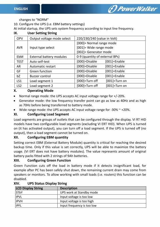
IX. User Setting String
OPV Output voltage mode select 220/230/240 (value in Volt)
AVR Input type select [000]= Normal range mode [001]= Wide range mode [002]= Generator mode
EbM External battery modules 0-9 (quantity of external BPs)
TEST Auto self-test [000]=Disable [001]=Enable
AR Automatic restart [000]=Disable [001]=Enable
GF Green function [000]=Disable [001]=Enable
bZ Buzzer control [000]=Disable [001]=Enable
LS1 Load segment 1 [000]=Turn off [001]=Turn on
LS2 Load segment 2 [000]=Turn off [001]=Turn on
X. Operating Mode
Normal range mode: the UPS accepts AC input voltage range for +/-20%.
Generator mode: the low frequency transfer point can go as low as 40Hz and as high as 70Hz before being transferred to battery mode.
Wide range mode: the UPS accepts AC input voltage range for -30% ~ +20%.
XI. Configuring Load Segment
Load segments are groups of outlets that can be configured through the display. VI RT HID models have two configurable load segments (excluding VI ERT HID). When UPS is turned on (it has activated output), you can turn off a load segment. If the UPS is turned off (no output), then a load segment cannot be turned on.
XII. Configuring EBM quantity
Setting correct EBM (External Battery Module) quantity is critical for reaching the desired backup time. Only if this value is set correctly, UPS will be able to maximize the battery usage. (VI ERT does not have battery modules). The value represents amount of original battery packs fitted with 2 strings of 9Ah batteries.
XIII. Configuring Green Function
Green Function cuts off the load in battery mode if it detects insignificant load, for example after PC has been safely shut down, the remaining current drain may come from speakers or monitors. To allow working with small loads (i.e. routers) this function can be disabled.
XIV. UPS Status Display String LCD Display String Description STbY UPS work at Standby mode
IPVL Input voltage is too low
IPVH Input voltage is too high
IPFL Input frequency is too low
ENGLISH
IPFH Input frequency is too high
NORM UPS work at Line mode
AVR UPS work at AVR mode
bATT UPS work at Battery mode
TEST UPS work at battery life/function test mode
OPVH Battery mode, the output is too high
OPVL Battery mode, the output is too low
OPST Output short
OVLD Overload
bATH Battery voltage is too high
bATL Battery voltage is too low
OVTP Internal temperature is too high
FNLK Fan is locked
bTWK Batteries are weak
XV. Indicators and Audible alarm
Audible alarm
Backup Mode Sounding every 4seconds “bATT” on the screen
Low Battery Sounding every second “bATL” on the screen
UPS Fault Continuously Sounding Red display
Overload Sounding every second “OVLD” on the screen
Battery Replacement Sounding every second
Alarm can be muted when it is activated, but it will sound in case of low battery, fan fault, overheat and other major fault.
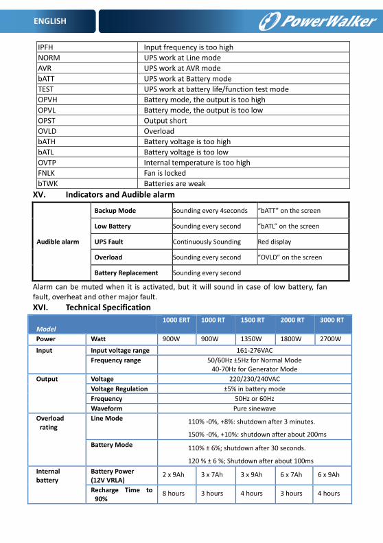
XVI. Technical Specification
Model
1000 ERT 1000 RT 1500 RT 2000 RT 3000 RT
Power Watt 900W 900W 1350W 1800W 2700W
Input Input voltage range 161-276VAC
Frequency range 50/60Hz ±5Hz for Normal Mode 40-70Hz for Generator Mode
Output Voltage 220/230/240VAC
Voltage Regulation ±5% in battery mode
Frequency 50Hz or 60Hz
Waveform Pure sinewave
Overload rating
Line Mode 110% -0%, +8%: shutdown after 3 minutes.
150% -0%, +10%: shutdown after about 200ms
Battery Mode 110% ± 6%; shutdown after 30 seconds.
120 % ± 6 %; Shutdown after about 100ms
Internal battery
Battery Power (12V VRLA)
2 x 9Ah 3 x 7Ah 3 x 9Ah 6 x 7Ah 6 x 9Ah
Recharge Time to 90%
8 hours 3 hours 4 hours 3 hours 4 hours

ENGLISH
Temperature 0 to 40°C
Humidity 20%-80% relative humidity (non-condensing)
Altitude <1500m
Storage Temperature -15 to 45 C
Net weight 15.0kg 17.8kg 17.8kg 27.8kg 27.8kg
Dimensions 438 X 86.5 x 436 438 X 86.5 x 608