quick start e - infoplc · codesys v3 quick start ... in our example we want to declare the input...
TRANSCRIPT
CODESYS V3 Quick Start
1/19
Programming a Garage Door Drive with CODESYS V3
On the following pages we would like to show you how easy it is to program a simple automation project with CODESYS V3. To start with, we would like to make you familiar with the actual task. In order to make it easier for you to follow us through the project we have divided the project into small easy to reproduce units. You can program the application step-by-step as we go along or you can download the complete project at the end of this tutorial. Depending on your pace it takes between 30 and 60 minutes to complete the project. Have fun! P.S. We rely on your feedback and very much appreciate your input. Should you have any questions or would like to post a comment or improvement suggestion please directly contact [email protected] (Roland Wagner). Please be aware of the fact that the application described is an example and is not meant for industrial usage. Contents 1) Task ...................................................................................................................................... 2 2) Project Configuration ............................................................................................................ 2 3) Declaration of variables ........................................................................................................ 7 4) Programming the Garage Door Drive ................................................................................... 8 5) Programming the Error Monitoring and the Lighting ........................................................... 12 6) Testing the Application ........................................................................................................ 15
www.infoPLC.net
CODESYS V3 Quick Start
2/19
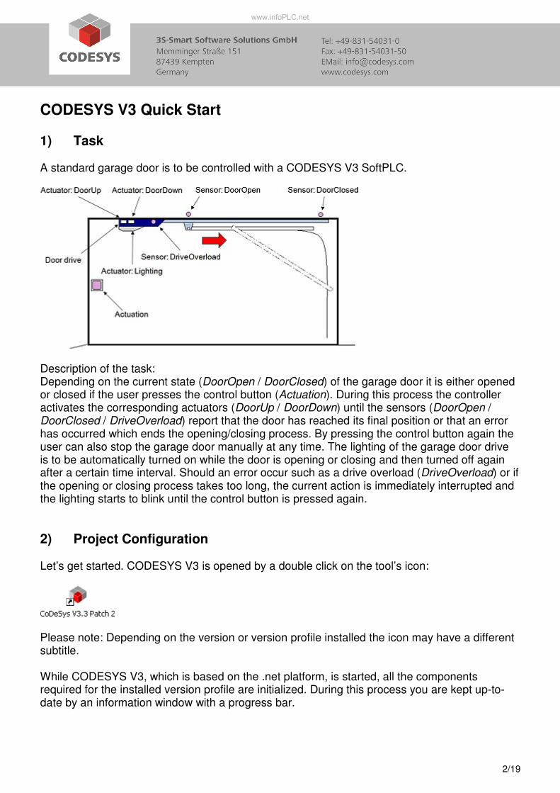
1) Task A standard garage door is to be controlled with a CODESYS V3 SoftPLC.
Description of the task: Depending on the current state (DoorOpen / DoorClosed) of the garage door it is either opened or closed if the user presses the control button (Actuation). During this process the controller activates the corresponding actuators (DoorUp / DoorDown) until the sensors (DoorOpen / DoorClosed / DriveOverload) report that the door has reached its final position or that an error has occurred which ends the opening/closing process. By pressing the control button again the user can also stop the garage door manually at any time. The lighting of the garage door drive is to be automatically turned on while the door is opening or closing and then turned off again after a certain time interval. Should an error occur such as a drive overload (DriveOverload) or if the opening or closing process takes too long, the current action is immediately interrupted and the lighting starts to blink until the control button is pressed again.
2) Project Configuration Let’s get started. CODESYS V3 is opened by a double click on the tool’s icon:
Please note: Depending on the version or version profile installed the icon may have a different subtitle. While CODESYS V3, which is based on the .net platform, is started, all the components required for the installed version profile are initialized. During this process you are kept up-to-date by an information window with a progress bar.
www.infoPLC.net
CODESYS V3 Quick Start
3/19
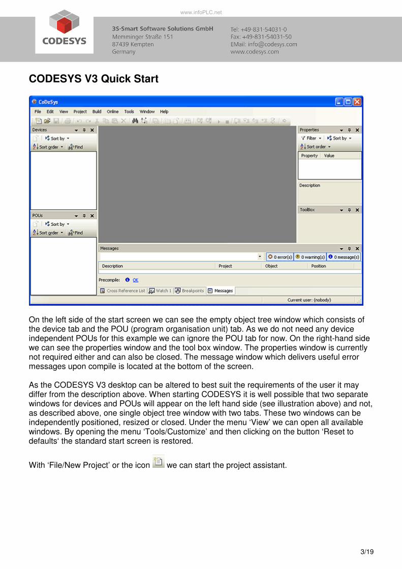
On the left side of the start screen we can see the empty object tree window which consists of the device tab and the POU (program organisation unit) tab. As we do not need any device independent POUs for this example we can ignore the POU tab for now. On the right-hand side we can see the properties window and the tool box window. The properties window is currently not required either and can also be closed. The message window which delivers useful error messages upon compile is located at the bottom of the screen. As the CODESYS V3 desktop can be altered to best suit the requirements of the user it may differ from the description above. When starting CODESYS it is well possible that two separate windows for devices and POUs will appear on the left hand side (see illustration above) and not, as described above, one single object tree window with two tabs. These two windows can be independently positioned, resized or closed. Under the menu ‘View’ we can open all available windows. By opening the menu ‘Tools/Customize’ and then clicking on the button ‘Reset to defaults‘ the standard start screen is restored.
With ‘File/New Project’ or the icon we can start the project assistant.
www.infoPLC.net
CODESYS V3 Quick Start
4/19
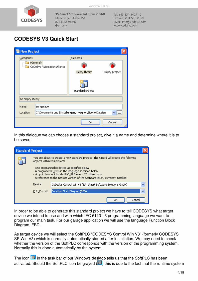
In this dialogue we can choose a standard project, give it a name and determine where it is to be saved.
In order to be able to generate this standard project we have to tell CODESYS what target device we intend to use and with which IEC 61131-3 programming language we want to program our main task. For our garage application we will use the language Function Block Diagram, FBD. As target device we will select the SoftPLC “CODESYS Control Win V3” (formerly CODESYS SP Win V3) which is normally automatically started after installation. We may need to check whether the version of the SoftPLC corresponds with the version of the programming system. Normally this is done automatically by the system.
The icon in the task bar of our Windows desktop tells us that the SoftPLC has been
activated. Should the SoftPLC icon be grayed ( ) this is due to the fact that the runtime system
www.infoPLC.net
CODESYS V3 Quick Start
5/19
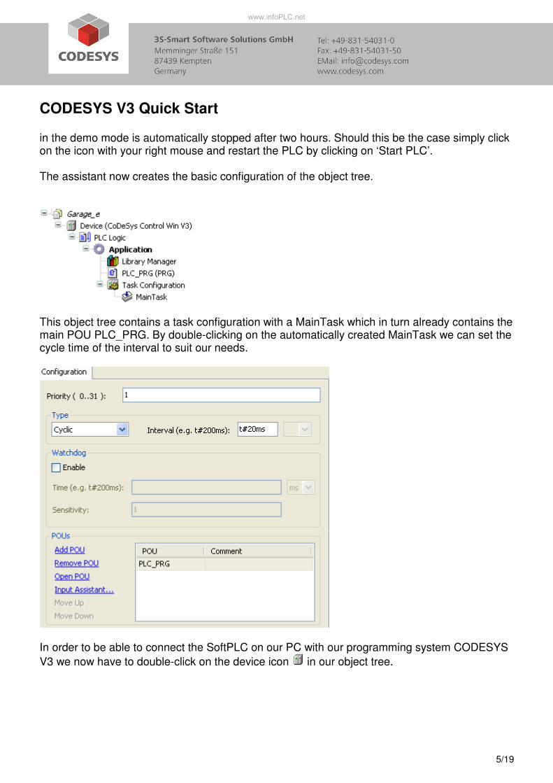
in the demo mode is automatically stopped after two hours. Should this be the case simply click on the icon with your right mouse and restart the PLC by clicking on ‘Start PLC’. The assistant now creates the basic configuration of the object tree.
This object tree contains a task configuration with a MainTask which in turn already contains the main POU PLC_PRG. By double-clicking on the automatically created MainTask we can set the cycle time of the interval to suit our needs.
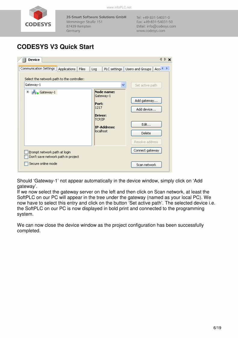
In order to be able to connect the SoftPLC on our PC with our programming system CODESYS
V3 we now have to double-click on the device icon in our object tree.
www.infoPLC.net
CODESYS V3 Quick Start
6/19
Should ‘Gateway-1’ not appear automatically in the device window, simply click on ‘Add gateway’. If we now select the gateway server on the left and then click on Scan network, at least the SoftPLC on our PC will appear in the tree under the gateway (named as your local PC). We now have to select this entry and click on the button ‘Set active path’. The selected device i.e. the SoftPLC on our PC is now displayed in bold print and connected to the programming system. We can now close the device window as the project configuration has been successfully completed.
www.infoPLC.net
CODESYS V3 Quick Start
7/19
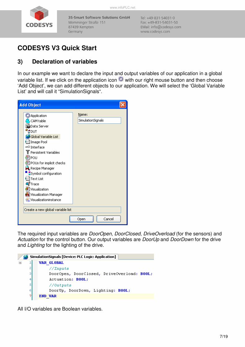
3) Declaration of variables In our example we want to declare the input and output variables of our application in a global
variable list. If we click on the application icon with our right mouse button and then choose ‘Add Object’, we can add different objects to our application. We will select the ‘Global Variable List’ and will call it “SimulationSignals“.
The required input variables are DoorOpen, DoorClosed, DriveOverload (for the sensors) and Actuation for the control button. Our output variables are DoorUp and DoorDown for the drive and Lighting for the lighting of the drive.
All I/O variables are Boolean variables.
www.infoPLC.net
CODESYS V3 Quick Start
8/19
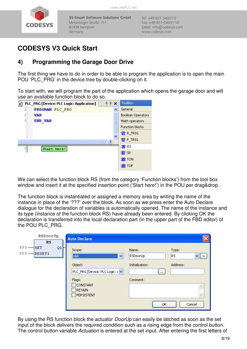
4) Programming the Garage Door Drive The first thing we have to do in order to be able to program the application is to open the main POU ‘PLC_PRG’ in the device tree by double-clicking on it. To start with, we will program the part of the application which opens the garage door and will use an available function block to do so.
We can select the function block RS (from the category ‘Function blocks’) from the tool box window and insert it at the specified insertion point (‘Start here!’) in the POU per drag&drop. The function block is instantiated or assigned a memory area by writing the name of the instance in place of the ‘???’ over the block. As soon as we press enter the Auto Declare dialogue for the declaration of variables is automatically opened. The name of the instance and its type (instance of the function block RS) have already been entered. By clicking OK the declaration is transferred into the local declaration part (in the upper part of the FBD editor) of the POU PLC_PRG.
By using the RS function block the actuator DoorUp can easily be latched as soon as the set input of the block delivers the required condition such as a rising edge from the control button. The control button variable Actuation is entered at the set input. After entering the first letters of
www.infoPLC.net
CODESYS V3 Quick Start
9/19
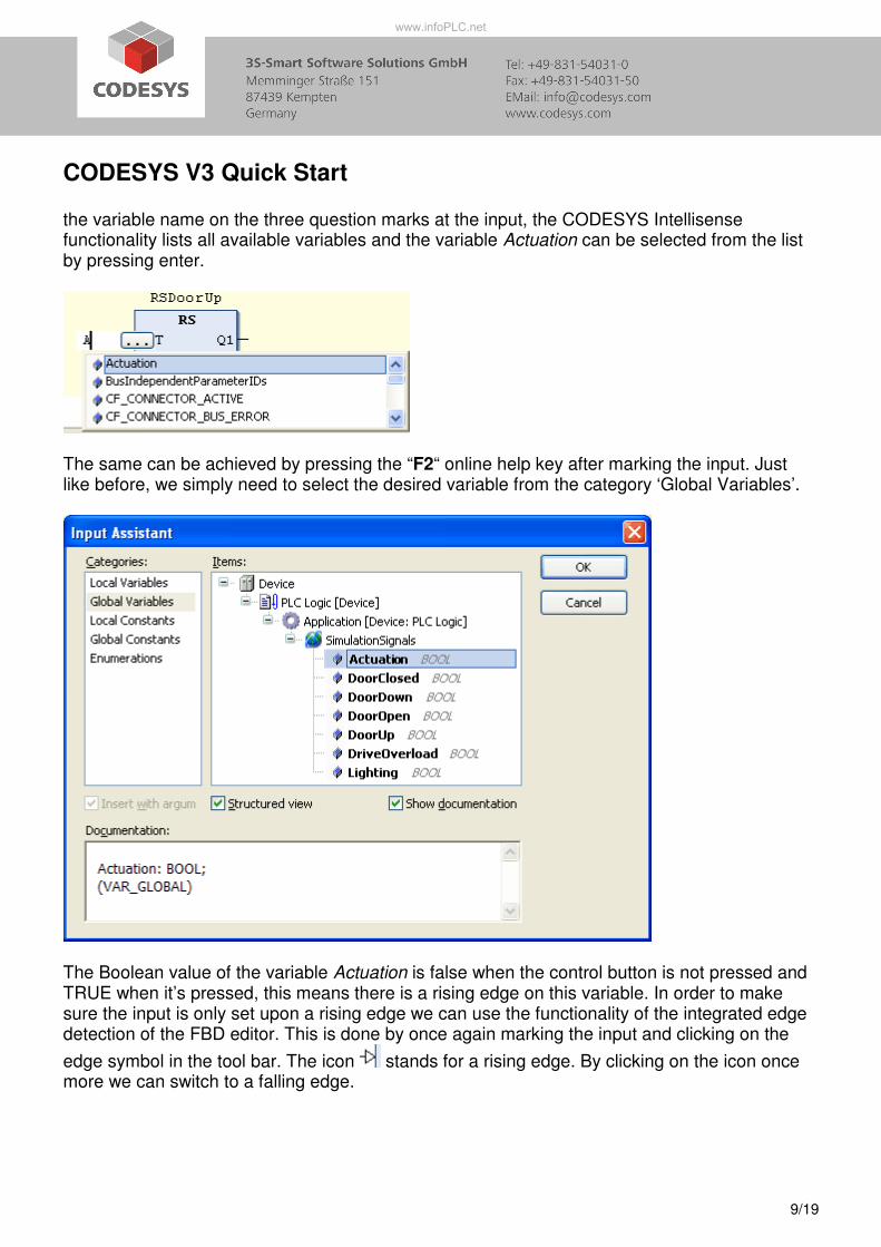
the variable name on the three question marks at the input, the CODESYS Intellisense functionality lists all available variables and the variable Actuation can be selected from the list by pressing enter.
The same can be achieved by pressing the “F2“ online help key after marking the input. Just like before, we simply need to select the desired variable from the category ‘Global Variables’.
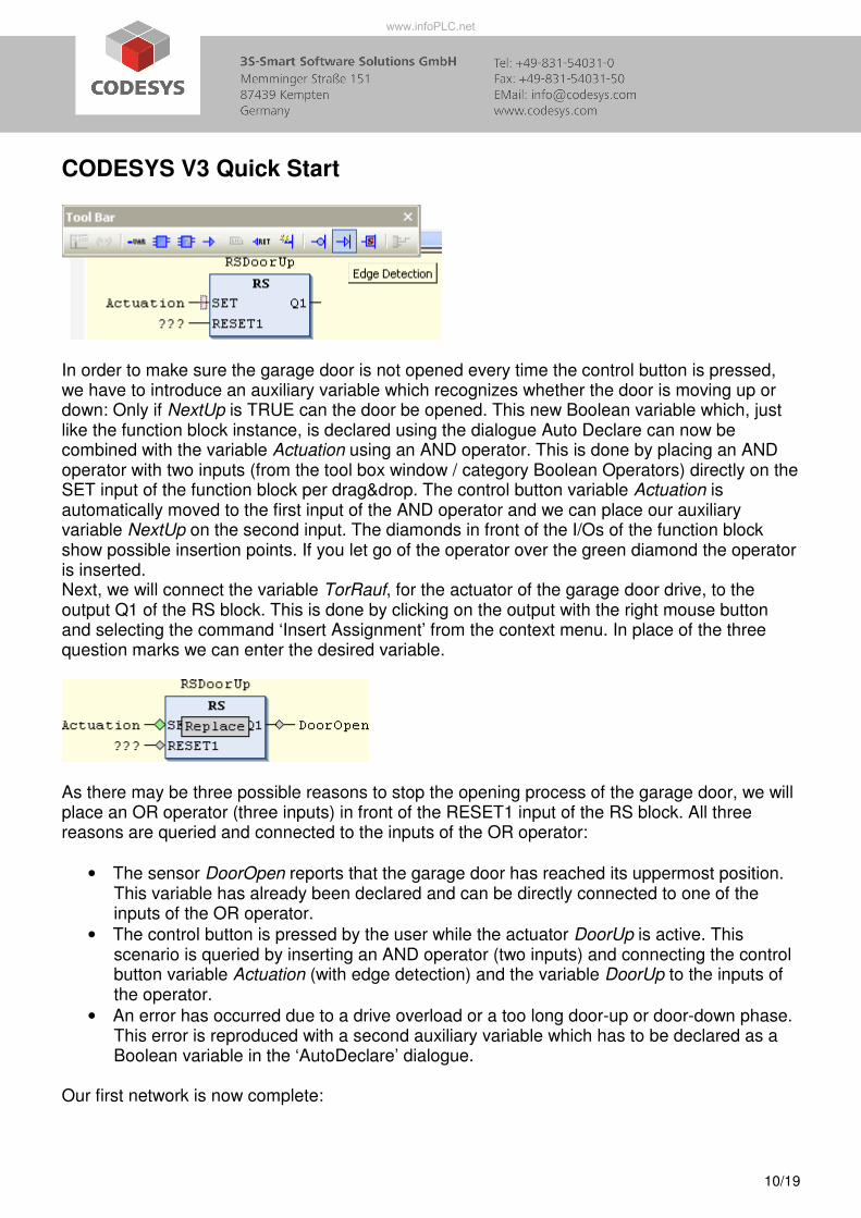
The Boolean value of the variable Actuation is false when the control button is not pressed and TRUE when it’s pressed, this means there is a rising edge on this variable. In order to make sure the input is only set upon a rising edge we can use the functionality of the integrated edge detection of the FBD editor. This is done by once again marking the input and clicking on the
edge symbol in the tool bar. The icon stands for a rising edge. By clicking on the icon once more we can switch to a falling edge.
www.infoPLC.net
CODESYS V3 Quick Start
10/19
In order to make sure the garage door is not opened every time the control button is pressed, we have to introduce an auxiliary variable which recognizes whether the door is moving up or down: Only if NextUp is TRUE can the door be opened. This new Boolean variable which, just like the function block instance, is declared using the dialogue Auto Declare can now be combined with the variable Actuation using an AND operator. This is done by placing an AND operator with two inputs (from the tool box window / category Boolean Operators) directly on the SET input of the function block per drag&drop. The control button variable Actuation is automatically moved to the first input of the AND operator and we can place our auxiliary variable NextUp on the second input. The diamonds in front of the I/Os of the function block show possible insertion points. If you let go of the operator over the green diamond the operator is inserted. Next, we will connect the variable TorRauf, for the actuator of the garage door drive, to the output Q1 of the RS block. This is done by clicking on the output with the right mouse button and selecting the command ‘Insert Assignment’ from the context menu. In place of the three question marks we can enter the desired variable.
As there may be three possible reasons to stop the opening process of the garage door, we will place an OR operator (three inputs) in front of the RESET1 input of the RS block. All three reasons are queried and connected to the inputs of the OR operator:
• The sensor DoorOpen reports that the garage door has reached its uppermost position. This variable has already been declared and can be directly connected to one of the inputs of the OR operator.
• The control button is pressed by the user while the actuator DoorUp is active. This scenario is queried by inserting an AND operator (two inputs) and connecting the control button variable Actuation (with edge detection) and the variable DoorUp to the inputs of the operator.
• An error has occurred due to a drive overload or a too long door-up or door-down phase. This error is reproduced with a second auxiliary variable which has to be declared as a Boolean variable in the ‘AutoDeclare’ dialogue.
Our first network is now complete:
www.infoPLC.net
CODESYS V3 Quick Start
11/19
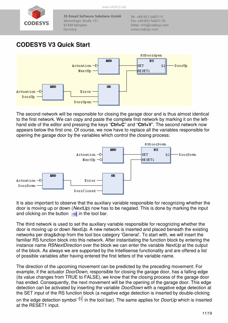
The second network will be responsible for closing the garage door and is thus almost identical to the first network. We can copy and paste the complete first network by marking it on the left-hand side of the editor and pressing the keys ”Ctrl+C” and “Ctrl+V”. The second network now appears below the first one. Of course, we now have to replace all the variables responsible for opening the garage door by the variables which control the closing process:
It is also important to observe that the auxiliary variable responsible for recognizing whether the door is moving up or down (NextUp) now has to be negated. This is done by marking the input and clicking on the button in the tool bar. The third network is used to set the auxiliary variable responsible for recognizing whether the door is moving up or down NextUp. A new network is inserted and placed beneath the existing networks per drag&drop from the tool box category ‘General’. To start with, we will insert the familiar RS function block into this network. After instantiating the function block by entering the instance name RSNextDirection over the block we can enter the variable NextUp at the output of the block. As always we are supported by the Intellisense functionality and are offered a list of possible variables after having entered the first letters of the variable name. The direction of the upcoming movement can be predicted by the preceding movement: For example, if the actuator DoorDown, responsible for closing the garage door, has a falling edge (its value changes from TRUE to FALSE), we know that the closing process of the garage door has ended. Consequently, the next movement will be the opening of the garage door. This edge detection can be activated by inserting the variable DoorDown with a negative edge detection at the SET input of the RS function block (a negative edge detection is inserted by double-clicking
on the edge detection symbol in the tool bar). The same applies for DoorUp which is inserted at the RESET1 input.
www.infoPLC.net
CODESYS V3 Quick Start
12/19
All that is needed to control the garage door is now complete. What is still missing is the control of the lighting and the required error monitoring for our garage door.
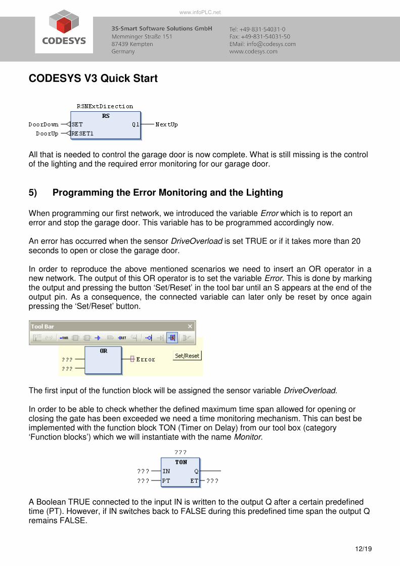
5) Programming the Error Monitoring and the Lighting When programming our first network, we introduced the variable Error which is to report an error and stop the garage door. This variable has to be programmed accordingly now. An error has occurred when the sensor DriveOverload is set TRUE or if it takes more than 20 seconds to open or close the garage door. In order to reproduce the above mentioned scenarios we need to insert an OR operator in a new network. The output of this OR operator is to set the variable Error. This is done by marking the output and pressing the button ‘Set/Reset’ in the tool bar until an S appears at the end of the output pin. As a consequence, the connected variable can later only be reset by once again pressing the ‘Set/Reset’ button.
The first input of the function block will be assigned the sensor variable DriveOverload. In order to be able to check whether the defined maximum time span allowed for opening or closing the gate has been exceeded we need a time monitoring mechanism. This can best be implemented with the function block TON (Timer on Delay) from our tool box (category ‘Function blocks’) which we will instantiate with the name Monitor. A Boolean TRUE connected to the input IN is written to the output Q after a certain predefined time (PT). However, if IN switches back to FALSE during this predefined time span the output Q remains FALSE.
www.infoPLC.net
CODESYS V3 Quick Start
13/19
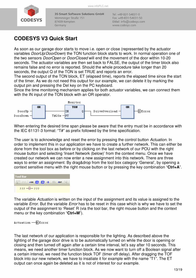
As soon as our garage door starts to move i.e. open or close (represented by the actuator variables DoorUp/DoorDown) the TON function block starts to work. In normal operation one of the two sensors DoorOpen or DoorClosed will end the movement of the door within 10-20 seconds. The actuator variables are then set back to FALSE, the output of the timer block also remains false and no error is reported. Should the whole procedure take longer than 20 seconds, the output Q of the TON is set TRUE and reports an error. The second output of the TON block, ET (elapsed time), reports the elapsed time since the start of the timer. As we do not need this output for our example, we can delete it by marking the output pin and pressing the Del key on the PC keyboard. Since the time monitoring mechanism applies for both actuator variables, we can connect them with the IN input of the TON block with an OR operator.
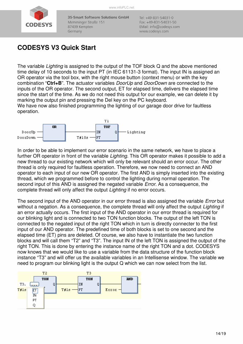
When entering the desired time span please be aware that the entry must be in accordance with the IEC 61131-3 format: “T#” as prefix followed by the time specification. The user is to acknowledge and reset the error by pressing the control button Actuation. In order to implement this in our application we have to create a further network. This can either be done from the tool box as before or by clicking on the last network of our POU with the right mouse button and selecting ‘Insert Network (below)’ from the context menu. Once we have created our network we can now enter a new assignment into this network. There are three ways to enter an assignment: By drag&drop from the tool box category ‘General’, by opening a context sensitive menu with the right mouse button or by pressing the key combination “Ctrl+A”.
The variable Actuation is written on the input of the assignment and its value is assigned to the variable Error. But the variable Error has to be reset in this case which is why we have to set the output of the assignment to ‘Reset’ R (via the tool bar, the right mouse button and the context menu or the key combination “Ctrl+M”).
The last network of our application is responsible for the lighting. As described above the lighting of the garage door drive is to be automatically turned on while the door is opening or closing and then turned off again after a certain time interval, let’s say after 10 seconds. This means, we need another timer function block. As we now want to turn off a Boolean signal after a certain interval, we need the function block TOF (timer off delay). After dragging the TOF block into our new network, we have to insatiate it for example with the name “T1”. The ET output can once again be deleted as it is not of interest for our example.
www.infoPLC.net
CODESYS V3 Quick Start
14/19
The variable Lighting is assigned to the output of the TOF block Q and the above mentioned time delay of 10 seconds to the input PT (in IEC 61131-3 format). The input IN is assigned an OR operator via the tool box, with the right mouse button (context menu) or with the key combination “Ctrl+B”. The actuator variables DoorUp and DoorDown are connected to the inputs of the OR operator. The second output, ET for elapsed time, delivers the elapsed time since the start of the time. As we do not need this output for our example, we can delete it by marking the output pin and pressing the Del key on the PC keyboard. We have now also finished programming the lighting of our garage door drive for faultless operation.
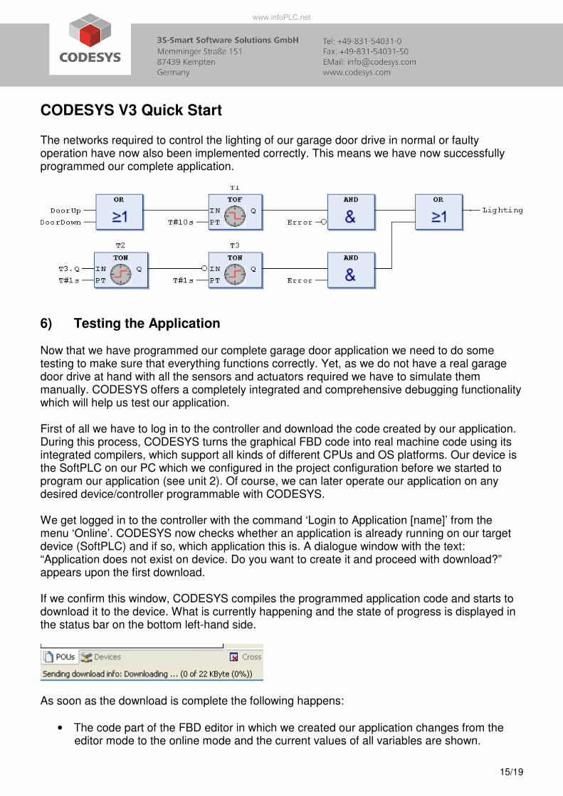
In order to be able to implement our error scenario in the same network, we have to place a further OR operator in front of the variable Lighting. This OR operator makes it possible to add a new thread to our existing network which will only be relevant should an error occur. The other thread is only required for faultless operation. Therefore, we now need to connect an AND operator to each input of our new OR operator. The first AND is simply inserted into the existing thread, which we programmed before to control the lighting during normal operation. The second input of this AND is assigned the negated variable Error. As a consequence, the complete thread will only affect the output Lighting if no error occurs. The second input of the AND operator in our error thread is also assigned the variable Error but without a negation. As a consequence, the complete thread will only affect the output Lighting if an error actually occurs. The first input of the AND operator in our error thread is required for our blinking light and is connected to two TON function blocks. The output of the left TON is connected to the negated input of the right TON which in turn is directly connecter to the first input of our AND operator. The predefined time of both blocks is set to one second and the elapsed time (ET) pins are deleted. Of course, we also have to instantiate the two function blocks and will call them “T2” and “T3”. The input IN of the left TON is assigned the output of the right TON. This is done by entering the instance name of the right TON and a dot. CODESYS now knows that we would like to use a variable from the data structure of the function block instance “T3” and will offer us the available variables in an Intellisense window. The variable we need to program our blinking light is the output Q which we can now select from the list.
www.infoPLC.net
CODESYS V3 Quick Start
15/19
The networks required to control the lighting of our garage door drive in normal or faulty operation have now also been implemented correctly. This means we have now successfully programmed our complete application.
6) Testing the Application Now that we have programmed our complete garage door application we need to do some testing to make sure that everything functions correctly. Yet, as we do not have a real garage door drive at hand with all the sensors and actuators required we have to simulate them manually. CODESYS offers a completely integrated and comprehensive debugging functionality which will help us test our application. First of all we have to log in to the controller and download the code created by our application. During this process, CODESYS turns the graphical FBD code into real machine code using its integrated compilers, which support all kinds of different CPUs and OS platforms. Our device is the SoftPLC on our PC which we configured in the project configuration before we started to program our application (see unit 2). Of course, we can later operate our application on any desired device/controller programmable with CODESYS. We get logged in to the controller with the command ‘Login to Application [name]’ from the menu ‘Online’. CODESYS now checks whether an application is already running on our target device (SoftPLC) and if so, which application this is. A dialogue window with the text: “Application does not exist on device. Do you want to create it and proceed with download?” appears upon the first download. If we confirm this window, CODESYS compiles the programmed application code and starts to download it to the device. What is currently happening and the state of progress is displayed in the status bar on the bottom left-hand side.
As soon as the download is complete the following happens:
• The code part of the FBD editor in which we created our application changes from the editor mode to the online mode and the current values of all variables are shown.
www.infoPLC.net
CODESYS V3 Quick Start
16/19
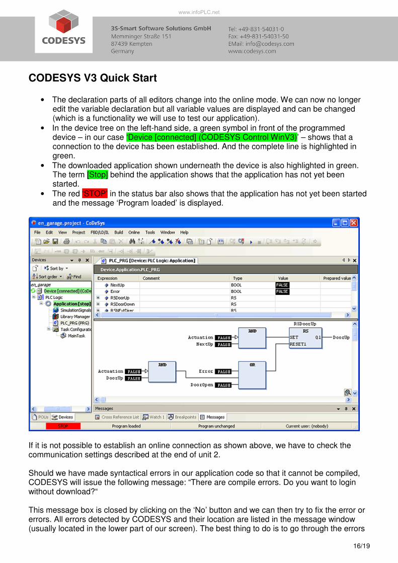
• The declaration parts of all editors change into the online mode. We can now no longer edit the variable declaration but all variable values are displayed and can be changed (which is a functionality we will use to test our application).
• In the device tree on the left-hand side, a green symbol in front of the programmed device – in our case ‘Device [connected] (CODESYS Control WinV3)’ – shows that a connection to the device has been established. And the complete line is highlighted in green.
• The downloaded application shown underneath the device is also highlighted in green. The term [Stop] behind the application shows that the application has not yet been started.
• The red ‘STOP’ in the status bar also shows that the application has not yet been started and the message ‘Program loaded’ is displayed.
If it is not possible to establish an online connection as shown above, we have to check the communication settings described at the end of unit 2. Should we have made syntactical errors in our application code so that it cannot be compiled, CODESYS will issue the following message: “There are compile errors. Do you want to login without download?“ This message box is closed by clicking on the ‘No’ button and we can then try to fix the error or errors. All errors detected by CODESYS and their location are listed in the message window (usually located in the lower part of our screen). The best thing to do is to go through the errors
www.infoPLC.net
CODESYS V3 Quick Start
17/19
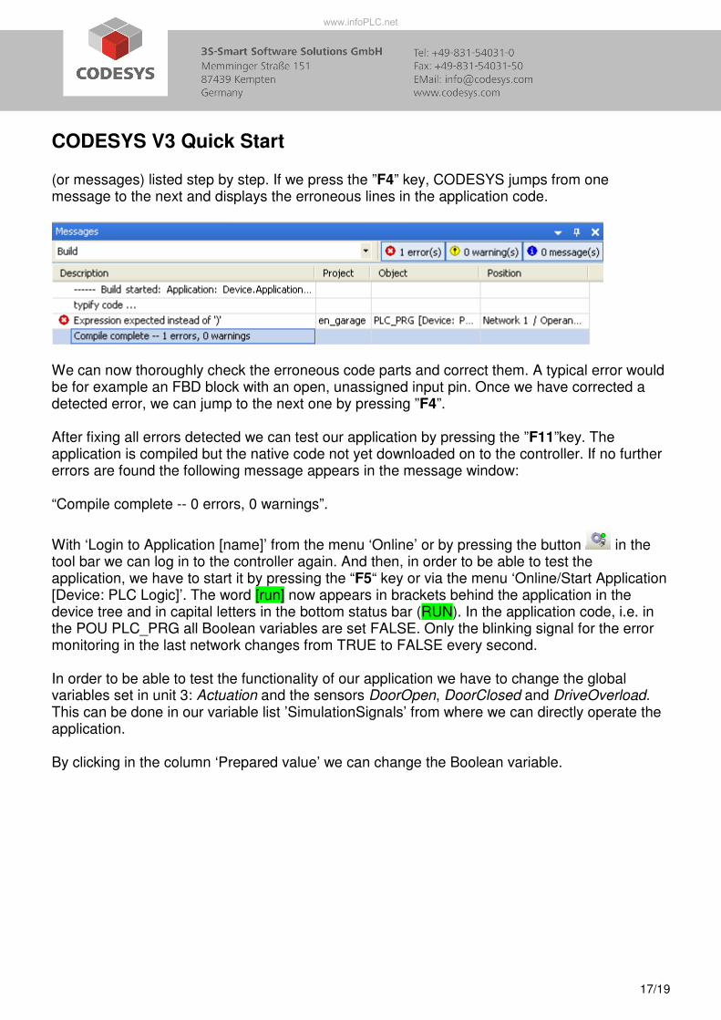
(or messages) listed step by step. If we press the ”F4” key, CODESYS jumps from one message to the next and displays the erroneous lines in the application code.
We can now thoroughly check the erroneous code parts and correct them. A typical error would be for example an FBD block with an open, unassigned input pin. Once we have corrected a detected error, we can jump to the next one by pressing ”F4”. After fixing all errors detected we can test our application by pressing the ”F11”key. The application is compiled but the native code not yet downloaded on to the controller. If no further errors are found the following message appears in the message window: “Compile complete -- 0 errors, 0 warnings”.
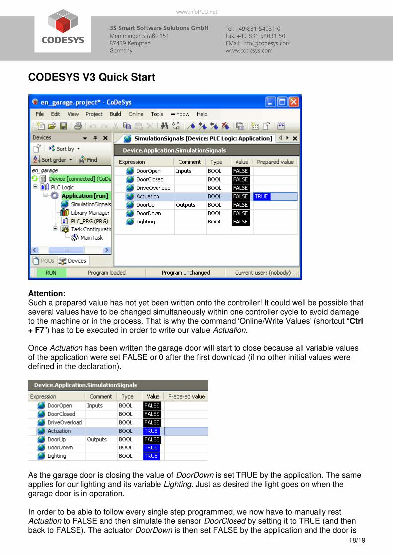
With ‘Login to Application [name]’ from the menu ‘Online’ or by pressing the button in the tool bar we can log in to the controller again. And then, in order to be able to test the application, we have to start it by pressing the “F5“ key or via the menu ‘Online/Start Application [Device: PLC Logic]’. The word [run] now appears in brackets behind the application in the device tree and in capital letters in the bottom status bar (RUN). In the application code, i.e. in the POU PLC_PRG all Boolean variables are set FALSE. Only the blinking signal for the error monitoring in the last network changes from TRUE to FALSE every second. In order to be able to test the functionality of our application we have to change the global variables set in unit 3: Actuation and the sensors DoorOpen, DoorClosed and DriveOverload. This can be done in our variable list ’SimulationSignals’ from where we can directly operate the application. By clicking in the column ‘Prepared value’ we can change the Boolean variable.
www.infoPLC.net
CODESYS V3 Quick Start
18/19
Attention: Such a prepared value has not yet been written onto the controller! It could well be possible that several values have to be changed simultaneously within one controller cycle to avoid damage to the machine or in the process. That is why the command ‘Online/Write Values’ (shortcut “Ctrl + F7”) has to be executed in order to write our value Actuation. Once Actuation has been written the garage door will start to close because all variable values of the application were set FALSE or 0 after the first download (if no other initial values were defined in the declaration).
As the garage door is closing the value of DoorDown is set TRUE by the application. The same applies for our lighting and its variable Lighting. Just as desired the light goes on when the garage door is in operation. In order to be able to follow every single step programmed, we now have to manually rest Actuation to FALSE and then simulate the sensor DoorClosed by setting it to TRUE (and then back to FALSE). The actuator DoorDown is then set FALSE by the application and the door is
www.infoPLC.net
CODESYS V3 Quick Start
19/19
closed. After 10 seconds the light is automatically turned off and the variable Lighting is set FALSE. By once more pressing the control button, i.e. by setting the variable Actuation TRUE we can test the opening procedure of the gate. The variables involved are now the variables needed for opening the gate DoorUp and DoorOpen. If we do not manually end the opening or closing procedure by simulating the sensor variables DoorClosed or DoorOpen, the application recognizes an error after the predefined time of 20 seconds, allowed for these procedures, has elapsed. As a consequence, the actuator DoorDown or DoorUp is set FALSE and the light starts to blink and the variable Lighting changes from TRUE to FALSE. By once more pressing the control button (Actuation is set TRUE) the error is acknowledged, the light stops blinking and we have returned to our initial state. The error DriveOverload can be tested by manually setting it TRUE while the gate is opening or closing. Again the garage door is stopped and the error is signalled by the blinking light.
www.infoPLC.net