quick start powerflex 40p adjustable frequency ac drive 40p_… · powerflex® 40p adjustable...
TRANSCRIPT
Quick StartPowerFlex® 40P AdjustableFrequency AC DriveFRN 1.xx - 2.xxThis Quick Start guide summarizes the basic steps needed to install, start-up and program the PowerFlex 40P Adjustable Frequency AC Drive. The information provided Does Not replace the User Manual and is intended for qualified drive service personnel only.For detailed PowerFlex 40P information including EMC instructions, application considerations and related precautions, refer to the PowerFlex 40P User Manual, Publication 22D-UM001… at www.rockwellautomation.com/literature.
General Precautions
!ATTENTION: The drive contains high voltage capacitors which take time to discharge after removal of mains supply. Before working on drive, ensure isolation of mains supply from line inputs [R, S, T (L1, L2, L3)]. Wait three minutes for capacitors to discharge to safe voltage levels. Failure to do so may result in personal injury or death.
Darkened display LEDs is not an indication that capacitors have discharged to safe voltage levels.
ATTENTION: Equipment damage and/or personal injury may result if parameter A092 [Auto Rstrt Tries] or A094 [Start At PowerUp] is used in an inappropriate application. Do not use this function without considering applicable local, national and international codes, standards, regulations or industry guidelines.
ATTENTION: Only qualified personnel familiar with adjustable frequency AC drives and associated machinery should plan or implement the installation, start-up and subsequent maintenance of the system. Failure to comply may result in personal injury and/or equipment damage.
ATTENTION: This drive contains ESD (Electrostatic Discharge) sensitive parts and assemblies. Static control precautions are required when installing, testing, servicing or repairing this assembly. Component damage may result if ESD control procedures are not followed. If you are not familiar with static control procedures, reference A-B publication 8000-4.5.2, “Guarding Against Electrostatic Damage” or any other applicable ESD protection handbook.
ATTENTION: An incorrectly applied or installed drive can result in component damage or a reduction in product life. Wiring or application errors, such as, undersizing the motor, incorrect or inadequate AC supply, or excessive ambient temperatures may result in malfunction of the system.
ATTENTION: Risk of injury or equipment damage exists. Drive does not contain user-serviceable components. Do not disassemble drive chassis.
English-2
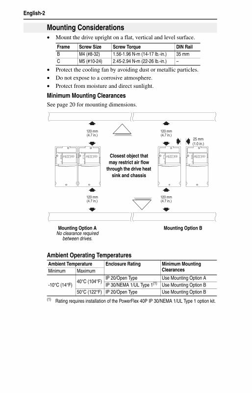
• Mount the drive upright on a flat, vertical and level surface.
• Protect the cooling fan by avoiding dust or metallic particles.• Do not expose to a corrosive atmosphere.• Protect from moisture and direct sunlight.
Minimum Mounting ClearancesSee page 20 for mounting dimensions.
Ambient Operating Temperatures
Mounting Considerations
Frame Screw Size Screw Torque DIN RailB M4 (#8-32) 1.56-1.96 N-m (14-17 lb.-in.) 35 mmC M5 (#10-24) 2.45-2.94 N-m (22-26 lb.-in.) –
Ambient Temperature Enclosure Rating Minimum Mounting ClearancesMinimum Maximum
-10°C (14°F)40°C (104°F)
IP 20/Open Type Use Mounting Option AIP 30/NEMA 1/UL Type 1(1)
(1) Rating requires installation of the PowerFlex 40P IP 30/NEMA 1/UL Type 1 option kit.
Use Mounting Option B50°C (122°F) IP 20/Open Type Use Mounting Option B
25 mm(1.0 in.)
120 mm(4.7 in.)
120 mm(4.7 in.)
120 mm(4.7 in.)
120 mm(4.7 in.)
RUNREV
FAULT
RUNREV
FAULT
RUNREV
FAULT
RUNREV
FAULT
Mounting Option ANo clearance required
between drives.
Mounting Option B
Closest object that may restrict air flow
through the drive heat sink and chassis
English-3
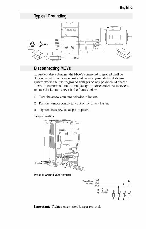
To prevent drive damage, the MOVs connected to ground shall be disconnected if the drive is installed on an ungrounded distribution system where the line-to-ground voltages on any phase could exceed 125% of the nominal line-to-line voltage. To disconnect these devices, remove the jumper shown in the figures below.
1. Turn the screw counterclockwise to loosen.
2. Pull the jumper completely out of the drive chassis.
3. Tighten the screw to keep it in place.
Jumper Location
Phase to Ground MOV Removal
Important: Tighten screw after jumper removal.
Typical Grounding
SHLD
U/T1V/T2W/T3
R/L1
S/L2
T/L3
RUNREV
FAULT
Disconnecting MOVs
R/L1S/L2T/L3
1 2 3 4
Three-PhaseAC Input
Jumper
English-4
Refer to the PowerFlex 40P User Manual for details on how to comply with the Low Voltage (LV) and Electromagnetic Compatibility (EMC) Directives.
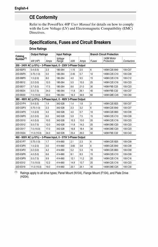
Drive Ratings
CE Conformity
Specifications, Fuses and Circuit Breakers
Catalog Number(1)
Output Ratings Input Ratings Branch Circuit Protection
kW (HP) AmpsVoltage Range kVA Amps Fuses
140M Motor Protectors Contactors
200 - 240V AC (±10%) – 3-Phase Input, 0 - 230V 3-Phase Output
22D-B2P3 0.4 (0.5) 2.3 180-264 1.15 2.5 6 140M-C2E-B40 100-C07
22D-B5P0 0.75 (1.0) 5.0 180-264 2.45 5.7 10 140M-C2E-C10 100-C09
22D-B8P0 1.5 (2.0) 8.0 180-264 4.0 9.5 15 140M-C2E-C16 100-C12
22D-B012 2.2 (3.0) 12.0 180-264 5.5 15.5 25 140M-C2E-C16 100-C23
22D-B017 3.7 (5.0) 17.5 180-264 8.6 21.0 30 140M-F8E-C25 100-C23
22D-B024 5.5 (7.5) 24.0 180-264 11.8 26.1 40 140M-F8E-C32 100-C37
22D-B033 7.5 (10.0) 33.0 180-264 16.3 34.6 60 140M-G8E-C45 100-C60
380 - 480V AC (±10%) – 3-Phase Input, 0 - 460V 3-Phase Output
22D-D1P4 0.4 (0.5) 1.4 342-528 1.4 1.8 3 140M-C2E-B25 100-C07
22D-D2P3 0.75 (1.0) 2.3 342-528 2.3 3.2 6 140M-C2E-B40 100-C07
22D-D4P0 1.5 (2.0) 4.0 342-528 4.0 5.7 10 140M-C2E-B63 100-C09
22D-D6P0 2.2 (3.0) 6.0 342-528 5.9 7.5 15 140M-C2E-C10 100-C09
22D-D010 4.0 (5.0) 10.5 342-528 10.3 13.0 20 140M-C2E-C16 100-C23
22D-D012 5.5 (7.5) 12.0 342-528 11.8 14.2 25 140M-D8E-C20 100-C23
22D-D017 7.5 (10.0) 17.0 342-528 16.8 18.4 30 140M-D8E-C20 100-C23
22D-D024 11.0 (15.0) 24.0 342-528 23.4 26.0 50 140M-F8E-C32 100-C43
460 - 600V AC (±10%) – 3-Phase Input, 0 - 575V 3-Phase Output
22D-E1P7 0.75 (1.0) 1.7 414-660 2.1 2.3 6 140M-C2E-B25 100-C09
22D-E3P0 1.5 (2.0) 3.0 414-660 3.65 3.8 6 140M-C2E-B40 100-C09
22D-E4P2 2.2 (3.0) 4.2 414-660 5.2 5.3 10 140M-C2E-B63 100-C09
22D-E6P6 4.0 (5.0) 6.6 414-660 8.1 8.3 15 140M-C2E-C10 100-C09
22D-E9P9 5.5 (7.5) 9.9 414-660 12.1 11.2 20 140M-C2E-C16 100-C16
22D-E012 7.5 (10.0) 12.2 414-660 14.9 13.7 25 140M-C2E-C16 100-C23
22D-E019 11.0 (15.0) 19.0 414-660 23.1 24.1 40 140M-D8E-C25 100-C30
(1) Ratings apply to all drive types; Panel Mount (N104), Flange Mount (F104), and Plate Drive (H204).
English-5
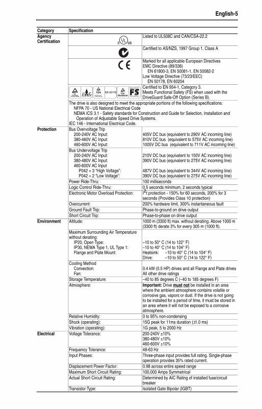
Category SpecificationAgency Certification
Listed to UL508C and CAN/CSA-22.2
Certified to AS/NZS, 1997 Group 1, Class A
Marked for all applicable European DirectivesEMC Directive (89/336)
EN 61800-3, EN 50081-1, EN 50082-2Low Voltage Directive (73/23/EEC)
EN 50178, EN 60204Certified to EN 954-1, Category 3.Meets Functional Safety (FS) when used with the DriveGuard Safe-Off Option (Series B).
The drive is also designed to meet the appropriate portions of the following specifications:NFPA 70 - US National Electrical CodeNEMA ICS 3.1 - Safety standards for Construction and Guide for Selection, Installation and
Operation of Adjustable Speed Drive Systems.IEC 146 - International Electrical Code.
Protection Bus Overvoltage Trip200-240V AC Input:380-460V AC Input:460-600V AC Input:
405V DC bus (equivalent to 290V AC incoming line)810V DC bus (equivalent to 575V AC incoming line)1005V DC bus (equivalent to 711V AC incoming line)
Bus Undervoltage Trip200-240V AC Input:380-480V AC Input:460-600V AC Input
P042 = 3 “High Voltage”:P042 = 2 “Low Voltage”:
210V DC bus (equivalent to 150V AC incoming line)390V DC bus (equivalent to 275V AC incoming line)
487V DC bus (equivalent to 344V AC incoming line)390V DC bus (equivalent to 275V AC incoming line)
Power Ride-Thru: 100 millisecondsLogic Control Ride-Thru: 0.5 seconds minimum, 2 seconds typicalElectronic Motor Overload Protection: I2t protection - 150% for 60 seconds, 200% for 3
seconds (Provides Class 10 protection)Overcurrent: 200% hardware limit, 300% instantaneous faultGround Fault Trip: Phase-to-ground on drive outputShort Circuit Trip: Phase-to-phase on drive output
Environment Altitude: 1000 m (3300 ft) max. without derating. Above 1000 m (3300 ft) derate 3% for every 305 m (1000 ft).
Maximum Surrounding Air Temperature without derating:
IP20, Open Type:IP30, NEMA Type 1, UL Type 1:Flange and Plate Mount:
–10 to 50° C (14 to 122° F)–10 to 40° C (14 to 104° F)Heatsink: –10 to 40° C (14 to 104° F)Drive: –10 to 50° C (14 to 122° F)
Cooling MethodConvection:Fan:
0.4 kW (0.5 HP) drives and all Flange and Plate drivesAll other drive ratings
Storage Temperature: –40 to 85 degrees C (–40 to 185 degrees F)Atmosphere: Important: Drive must not be installed in an area
where the ambient atmosphere contains volatile or corrosive gas, vapors or dust. If the drive is not going to be installed for a period of time, it must be stored in an area where it will not be exposed to a corrosive atmosphere.
Relative Humidity: 0 to 95% non-condensingShock (operating): 15G peak for 11ms duration (±1.0 ms)Vibration (operating): 1G peak, 5 to 2000 Hz
Electrical Voltage Tolerance: 200-240V ±10%380-480V ±10%460-600V ±10%
Frequency Tolerance: 48-63 HzInput Phases: Three-phase input provides full rating. Single-phase
operation provides 35% rated current.Displacement Power Factor: 0.98 across entire speed rangeMaximum Short Circuit Rating: 100,000 Amps SymmetricalActual Short Circuit Rating: Determined by AIC Rating of installed fuse/circuit
breakerTransistor Type: Isolated Gate Bipolar (IGBT)
UL®C US
TUV Rheinland
Product Safety
..
Production inspected
W
E C TUV Rheinland
..Functional
Safety
Bauart geprüft
Type approved
EN 50178
English-6
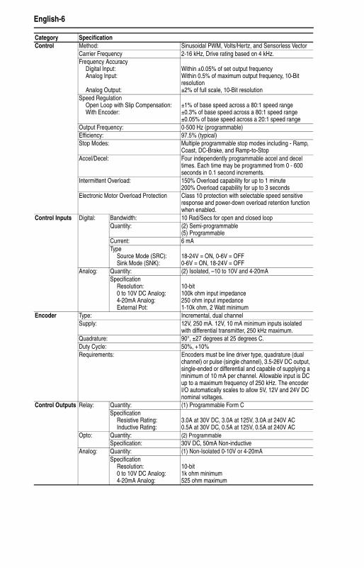
Control Method: Sinusoidal PWM, Volts/Hertz, and Sensorless VectorCarrier Frequency 2-16 kHz, Drive rating based on 4 kHz.Frequency Accuracy
Digital Input:Analog Input:
Analog Output:
Within ±0.05% of set output frequencyWithin 0.5% of maximum output frequency, 10-Bit resolution±2% of full scale, 10-Bit resolution
Speed RegulationOpen Loop with Slip Compensation:With Encoder:
±1% of base speed across a 80:1 speed range±0.3% of base speed across a 80:1 speed range±0.05% of base speed across a 20:1 speed range
Output Frequency: 0-500 Hz (programmable)Efficiency: 97.5% (typical)Stop Modes: Multiple programmable stop modes including - Ramp,
Coast, DC-Brake, and Ramp-to-StopAccel/Decel: Four independently programmable accel and decel
times. Each time may be programmed from 0 - 600 seconds in 0.1 second increments.
Intermittent Overload: 150% Overload capability for up to 1 minute200% Overload capability for up to 3 seconds
Electronic Motor Overload Protection Class 10 protection with selectable speed sensitive response and power-down overload retention function when enabled.
Control Inputs Digital: Bandwidth: 10 Rad/Secs for open and closed loopQuantity: (2) Semi-programmable
(5) ProgrammableCurrent: 6 mAType
Source Mode (SRC):Sink Mode (SNK):
18-24V = ON, 0-6V = OFF0-6V = ON, 18-24V = OFF
Analog: Quantity: (2) Isolated, –10 to 10V and 4-20mASpecification
Resolution:0 to 10V DC Analog:4-20mA Analog:External Pot:
10-bit100k ohm input impedance250 ohm input impedance1-10k ohm, 2 Watt minimum
Encoder Type: Incremental, dual channelSupply: 12V, 250 mA. 12V, 10 mA minimum inputs isolated
with differential transmitter, 250 kHz maximum.Quadrature: 90°, ±27 degrees at 25 degrees C.Duty Cycle: 50%, +10%Requirements: Encoders must be line driver type, quadrature (dual
channel) or pulse (single channel), 3.5-26V DC output, single-ended or differential and capable of supplying a minimum of 10 mA per channel. Allowable input is DC up to a maximum frequency of 250 kHz. The encoder I/O automatically scales to allow 5V, 12V and 24V DC nominal voltages.
Control Outputs Relay: Quantity: (1) Programmable Form CSpecification
Resistive Rating:Inductive Rating:
3.0A at 30V DC, 3.0A at 125V, 3.0A at 240V AC0.5A at 30V DC, 0.5A at 125V, 0.5A at 240V AC
Opto: Quantity: (2) ProgrammableSpecification: 30V DC, 50mA Non-inductive
Analog: Quantity: (1) Non-Isolated 0-10V or 4-20mASpecification
Resolution:0 to 10V DC Analog:4-20mA Analog:
10-bit1k ohm minimum525 ohm maximum
Category Specification
English-7
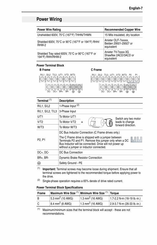
Power Terminal Block
Power Terminal Block Specifications
Power Wiring
Power Wire Rating Recommended Copper Wire
Unshielded 600V, 75°C (167°F) THHN/THWN 15 Mils insulated, dry location
Shielded 600V, 75°C or 90°C (167°F or 194°F) RHH/RHW-2
Anixter OLF-7xxxxx,Belden 29501-29507 or equivalent
Shielded Tray rated 600V, 75°C or 90°C (167°F or 194°F) RHH/RHW-2
Anixter 7V-7xxxx-3GShawflex 2ACD/3ACD or equivalent
Terminal (1) Description
R/L1, S/L2 1-Phase Input (2)
R/L1, S/L2, T/L3 3-Phase Input
U/T1 To Motor U/T1
=Switch any two motor leads to change forward direction.
V/T2 To Motor V/T2
W/T3 To Motor W/T3
P2, P1
DC Bus Inductor Connection (C Frame drives only.)
The C Frame drive is shipped with a jumper between Terminals P2 and P1. Remove this jumper only when a DC Bus Inductor will be connected. Drive will not power up without a jumper or inductor connected.
DC+, DC- DC Bus Connection
BR+, BR- Dynamic Brake Resistor Connection
Safety Ground - PE
(1) Important: Terminal screws may become loose during shipment. Ensure that all terminal screws are tightened to the recommended torque before applying power to the drive.
(2) Single-phase operation requires a 65% derate of drive rated current.
Frame Maximum Wire Size (1) Minimum Wire Size (1) Torque
B 5.3 mm2 (10 AWG) 1.3 mm2 (16 AWG) 1.7-2.2 N-m (16-19 lb.-in.)
C 8.4 mm2 (8 AWG) 1.3 mm2 (16 AWG) 2.9-3.7 N-m (26-33 lb.-in.)
(1) Maximum/minimum sizes that the terminal block will accept - these are not recommendations.
V/T2T/L3S/L2R/L1 U/T1 W/T3
BR+ BR-DC- DC+
V/T2T/L3S/L2R/L1 U/T1 W/T3 P2 P1
BR+ BR-DC- DC+
B Frame C Frame
English-8
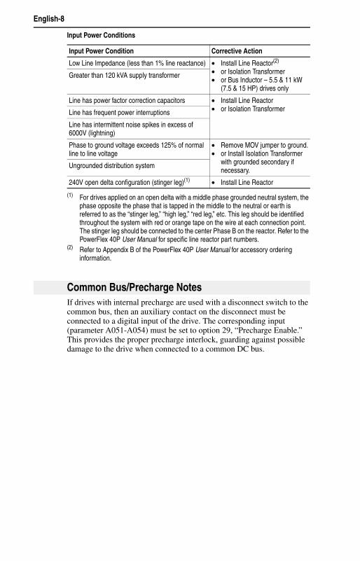
Input Power Conditions
If drives with internal precharge are used with a disconnect switch to the common bus, then an auxiliary contact on the disconnect must be connected to a digital input of the drive. The corresponding input (parameter A051-A054) must be set to option 29, “Precharge Enable.” This provides the proper precharge interlock, guarding against possible damage to the drive when connected to a common DC bus.
Input Power Condition Corrective Action
Low Line Impedance (less than 1% line reactance) • Install Line Reactor(2)
• or Isolation Transformer• or Bus Inductor – 5.5 & 11 kW
(7.5 & 15 HP) drives only
(2) Refer to Appendix B of the PowerFlex 40P User Manual for accessory ordering information.
Greater than 120 kVA supply transformer
Line has power factor correction capacitors • Install Line Reactor• or Isolation TransformerLine has frequent power interruptions
Line has intermittent noise spikes in excess of 6000V (lightning)
Phase to ground voltage exceeds 125% of normal line to line voltage
• Remove MOV jumper to ground.• or Install Isolation Transformer
with grounded secondary if necessary.
Ungrounded distribution system
240V open delta configuration (stinger leg)(1)
(1) For drives applied on an open delta with a middle phase grounded neutral system, the phase opposite the phase that is tapped in the middle to the neutral or earth is referred to as the “stinger leg,” “high leg,” “red leg,” etc. This leg should be identified throughout the system with red or orange tape on the wire at each connection point. The stinger leg should be connected to the center Phase B on the reactor. Refer to the PowerFlex 40P User Manual for specific line reactor part numbers.
• Install Line Reactor
Common Bus/Precharge Notes

English-9
Signal and Control Wire Types
Recommended Control Wire for Digital I/O
I/O Terminal Block Specifications
Refer to the PowerFlex 40P User Manual for recommendations on maximum power and control cable length.
I/O Wiring Recommendations
Signal Type/Where Used
Belden Wire Type(s)(1)
(or equivalent)
(1) Stranded or solid wire.
DescriptionMin. Insulation Rating
Analog I/O & PTC 8760/9460 0.750 mm2(18AWG), twisted pair, 100% shield with drain(3)
(3) If the wires are short and contained within a cabinet which has no sensitive circuits, the use of shielded wire may not be necessary, but is always recommended.
300V, 75-90° C(167-194° F)Remote Pot 8770 0.750 mm2(18AWG), 3
cond., shieldedEncoder/Pulse I/O 89730(2)
(2) 9728 or 9730 are equivalent and may be used but may not fit in the drive wire channel.
0.196 mm2(24AWG), individually shielded pairs
Type Wire Type(s) DescriptionMinimum Insulation Rating
Unshielded Per US NEC or applicable national or local code
– 300V, 60 degrees C (140 degrees F)Shielded Multi-conductor shielded
cable such as Belden 8770(or equiv.)
0.750 mm2(18AWG), 3 conductor, shielded.
Frame Maximum Wire Size (1)
(1) Maximum/minimum sizes that the terminal block will accept - these are not recommendations.
Minimum Wire Size (1) Torque
B & C 1.3 mm2 (16 AWG) 0.2 mm2 (24 AWG) 0.5-0.8 N-m (4.4-7 lb.-in.)
English-10
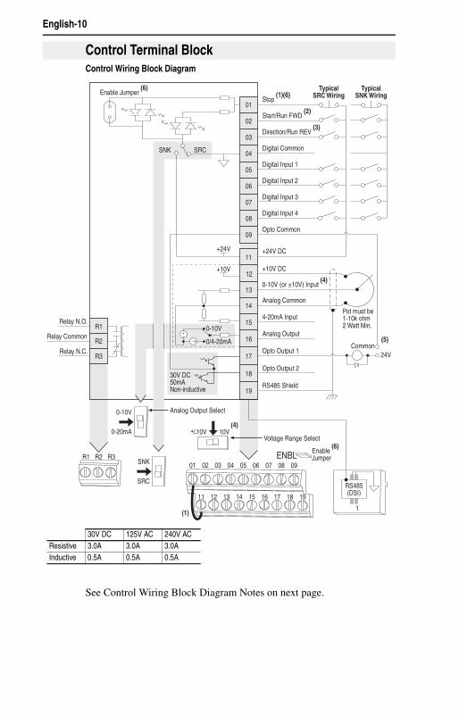
Control Wiring Block Diagram
See Control Wiring Block Diagram Notes on next page.
Control Terminal Block
04
05
06
07
01
02
03
08
09
11
12
13
14
15
16
17
18
19
Digital Common
Digital Input 1
Digital Input 2
Digital Input 3
Stop (1)(6)
Start/Run FWD (2)
Direction/Run REV (3)
Digital Input 4
Opto Common
R1
R2
R3
Relay N.O.
Relay Common
Relay N.C.
+24V DC
+10V DC
0-10V (or ±10V) Input (4)
Analog Common
4-20mA Input
Analog Output
Opto Output 1
Opto Output 2
RS485 Shield
+24V
+10V
TypicalSNK Wiring
TypicalSRC Wiring
1
RS485(DSI)
R1 R2 R3SNK
SRC
0-10V
0-20mA
01 02 03 04 05
11 12 13 14 15
06 07 08 09
16 17 18 19
(1)
Enable Jumper (6)
30V DC50mANon-inductive
Common24V
ENBL Enable (6)
Jumper
(5)
Pot must be1-10k ohm2 Watt Min.0-10V
0/4-20mA
Analog Output Select
Voltage Range Select
SRCSNK
10V+/-10V(4)
30V DC 125V AC 240V ACResistive 3.0A 3.0A 3.0AInductive 0.5A 0.5A 0.5A
English-11
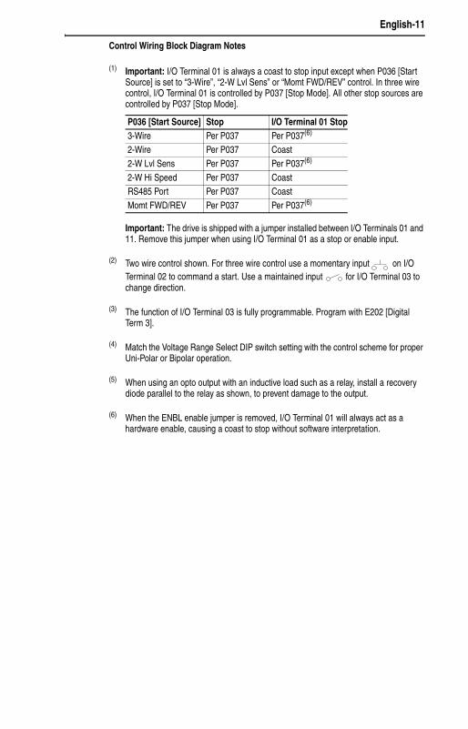
Control Wiring Block Diagram Notes
(1) Important: I/O Terminal 01 is always a coast to stop input except when P036 [Start Source] is set to “3-Wire”, “2-W Lvl Sens” or “Momt FWD/REV” control. In three wire control, I/O Terminal 01 is controlled by P037 [Stop Mode]. All other stop sources are controlled by P037 [Stop Mode].
Important: The drive is shipped with a jumper installed between I/O Terminals 01 and 11. Remove this jumper when using I/O Terminal 01 as a stop or enable input.
(2) Two wire control shown. For three wire control use a momentary input on I/O Terminal 02 to command a start. Use a maintained input for I/O Terminal 03 to change direction.
(3) The function of I/O Terminal 03 is fully programmable. Program with E202 [Digital Term 3].
(4) Match the Voltage Range Select DIP switch setting with the control scheme for proper Uni-Polar or Bipolar operation.
(5) When using an opto output with an inductive load such as a relay, install a recovery diode parallel to the relay as shown, to prevent damage to the output.
(6) When the ENBL enable jumper is removed, I/O Terminal 01 will always act as a hardware enable, causing a coast to stop without software interpretation.
P036 [Start Source] Stop I/O Terminal 01 Stop3-Wire Per P037 Per P037(6) 2-Wire Per P037 Coast2-W Lvl Sens Per P037 Per P037(6) 2-W Hi Speed Per P037 CoastRS485 Port Per P037 CoastMomt FWD/REV Per P037 Per P037(6)
English-12
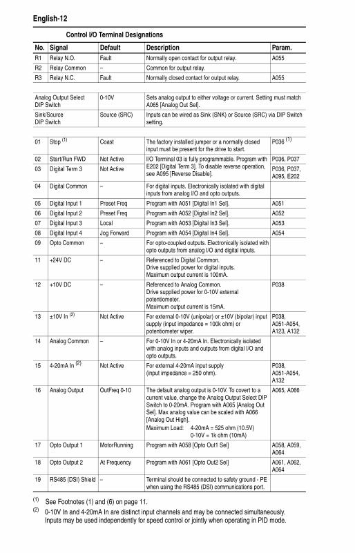
Control I/O Terminal Designations
No. Signal Default Description Param.R1 Relay N.O. Fault Normally open contact for output relay. A055
R2 Relay Common – Common for output relay.
R3 Relay N.C. Fault Normally closed contact for output relay. A055
Analog Output SelectDIP Switch
0-10V Sets analog output to either voltage or current. Setting must match A065 [Analog Out Sel].
Sink/SourceDIP Switch
Source (SRC) Inputs can be wired as Sink (SNK) or Source (SRC) via DIP Switch setting.
01 Stop (1) Coast The factory installed jumper or a normally closed input must be present for the drive to start.
P036 (1)
02 Start/Run FWD Not Active I/O Terminal 03 is fully programmable. Program with E202 [Digital Term 3]. To disable reverse operation, see A095 [Reverse Disable].
P036, P037
03 Digital Term 3 Not Active P036, P037, A095, E202
04 Digital Common – For digital inputs. Electronically isolated with digital inputs from analog I/O and opto outputs.
05 Digital Input 1 Preset Freq Program with A051 [Digital In1 Sel]. A051
06 Digital Input 2 Preset Freq Program with A052 [Digital In2 Sel]. A052
07 Digital Input 3 Local Program with A053 [Digital In3 Sel]. A053
08 Digital Input 4 Jog Forward Program with A054 [Digital In4 Sel]. A054
09 Opto Common – For opto-coupled outputs. Electronically isolated with opto outputs from analog I/O and digital inputs.
11 +24V DC – Referenced to Digital Common.Drive supplied power for digital inputs.Maximum output current is 100mA.
12 +10V DC – Referenced to Analog Common.Drive supplied power for 0-10V external potentiometer.Maximum output current is 15mA.
P038
13 ±10V In (2) Not Active For external 0-10V (unipolar) or ±10V (bipolar) input supply (input impedance = 100k ohm) or potentiometer wiper.
P038, A051-A054, A123, A132
14 Analog Common – For 0-10V In or 4-20mA In. Electronically isolated with analog inputs and outputs from digital I/O and opto outputs.
15 4-20mA In (2) Not Active For external 4-20mA input supply(input impedance = 250 ohm).
P038, A051-A054, A132
16 Analog Output OutFreq 0-10 The default analog output is 0-10V. To covert to a current value, change the Analog Output Select DIP Switch to 0-20mA. Program with A065 [Analog Out Sel]. Max analog value can be scaled with A066 [Analog Out High]. Maximum Load: 4-20mA = 525 ohm (10.5V)
0-10V = 1k ohm (10mA)
A065, A066
17 Opto Output 1 MotorRunning Program with A058 [Opto Out1 Sel] A058, A059, A064
18 Opto Output 2 At Frequency Program with A061 [Opto Out2 Sel] A061, A062, A064
19 RS485 (DSI) Shield – Terminal should be connected to safety ground - PE when using the RS485 (DSI) communications port.
(1) See Footnotes (1) and (6) on page 11.(2) 0-10V In and 4-20mA In are distinct input channels and may be connected simultaneously.
Inputs may be used independently for speed control or jointly when operating in PID mode.
English-13
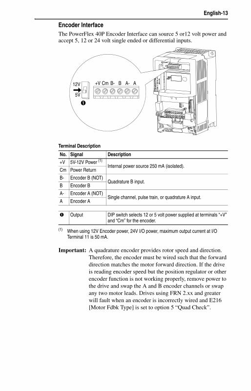
Encoder InterfaceThe PowerFlex 40P Encoder Interface can source 5 or12 volt power and accept 5, 12 or 24 volt single ended or differential inputs.
Terminal Description
Important: A quadrature encoder provides rotor speed and direction. Therefore, the encoder must be wired such that the forward direction matches the motor forward direction. If the drive is reading encoder speed but the position regulator or other encoder function is not working properly, remove power to the drive and swap the A and B encoder channels or swap any two motor leads. Drives using FRN 2.xx and greater will fault when an encoder is incorrectly wired and E216 [Motor Fdbk Type] is set to option 5 “Quad Check”.
No. Signal Description
+V 5V-12V Power (1)
(1) When using 12V Encoder power, 24V I/O power, maximum output current at I/O Terminal 11 is 50 mA.
Internal power source 250 mA (isolated).Cm Power Return
B- Encoder B (NOT)Quadrature B input.
B Encoder B
A- Encoder A (NOT)Single channel, pulse train, or quadrature A input.
A Encoder A
➊ Output DIP switch selects 12 or 5 volt power supplied at terminals “+V” and “Cm” for the encoder.
+V Cm B- B A- A12V
5V
➊
English-14
Before Applying Power to the Drive ❏ 1. Confirm that all inputs are connected to the correct terminals and are
secure.
❏ 2. Verify that AC line power at the disconnect device is within the rated value of the drive.
❏ 3. Verify that any digital control power is 24 volts.
❏ 4. Verify that the Sink (SNK)/Source (SRC) Setup DIP Switch is set to match your control wiring scheme. See page 10 for location.
Important: The default control scheme is Source (SRC). The Stop terminal is jumpered to allow starting from comms. If the control scheme is changed to Sink (SNK), the jumper must be removed from I/O Terminals 01 and 11 and installed between I/O Terminals 01 and 04.
❏ 5. Verify that the Stop input is present or the drive will not start.
Important: If I/O Terminal 01 is used as a stop input, the jumper between I/O Terminals 01 and 11 must be removed.
Applying Power to the Drive❏ 6. Apply AC power and control voltages to the drive.
Start, Stop, Direction and Speed Control
Factory default parameter values allow the drive to be controlled from comms. No programming is required to start, stop, change direction and control speed directly from comms.
Important: To disable reverse operation, see A095 [Reverse Disable].
If a fault appears on power up, refer to page 19 for an explanation of the fault code. For complete troubleshooting information, refer to the PowerFlex 40P User Manual.
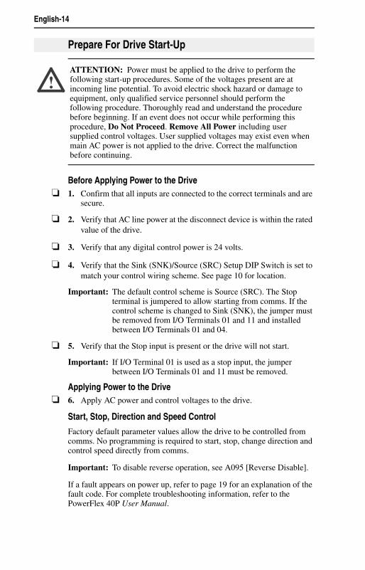
Prepare For Drive Start-Up
!ATTENTION: Power must be applied to the drive to perform the following start-up procedures. Some of the voltages present are at incoming line potential. To avoid electric shock hazard or damage to equipment, only qualified service personnel should perform the following procedure. Thoroughly read and understand the procedure before beginning. If an event does not occur while performing this procedure, Do Not Proceed. Remove All Power including user supplied control voltages. User supplied voltages may exist even when main AC power is not applied to the drive. Correct the malfunction before continuing.
English-15
For additional drive programming and control, a DSI remote HIM or PC programming tools (DriveExplorer™ or DriveTools™ SP) should be used.
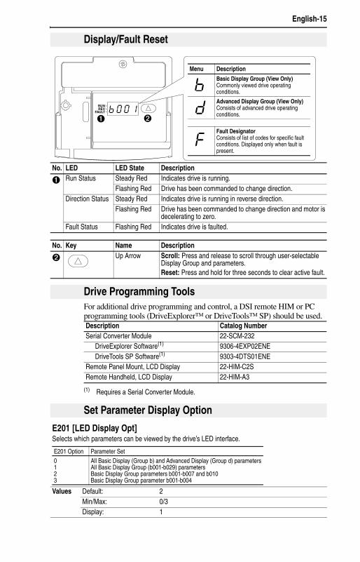
Display/Fault Reset
No. LED LED State Description
➊ Run Status Steady Red Indicates drive is running.Flashing Red Drive has been commanded to change direction.
Direction Status Steady Red Indicates drive is running in reverse direction.Flashing Red Drive has been commanded to change direction and motor is
decelerating to zero.Fault Status Flashing Red Indicates drive is faulted.
No. Key Name Description
➋ Up Arrow Scroll: Press and release to scroll through user-selectable Display Group and parameters.Reset: Press and hold for three seconds to clear active fault.
RUNREV
FAULT
➊ ➋
Menu Description
Basic Display Group (View Only)Commonly viewed drive operating conditions.
Advanced Display Group (View Only)Consists of advanced drive operating conditions.
Fault DesignatorConsists of list of codes for specific fault conditions. Displayed only when fault is present.
Drive Programming Tools
Description Catalog NumberSerial Converter Module 22-SCM-232
DriveExplorer Software(1)
(1) Requires a Serial Converter Module.
9306-4EXP02ENEDriveTools SP Software(1) 9303-4DTS01ENE
Remote Panel Mount, LCD Display 22-HIM-C2SRemote Handheld, LCD Display 22-HIM-A3
Set Parameter Display Option
E201 [LED Display Opt]Selects which parameters can be viewed by the drive’s LED interface.
Values Default: 2Min/Max: 0/3Display: 1
E201 Option Parameter Set0123
All Basic Display (Group b) and Advanced Display (Group d) parametersAll Basic Display Group (b001-b029) parametersBasic Display Group parameters b001-b007 and b010Basic Display Group parameter b001-b004
English-16
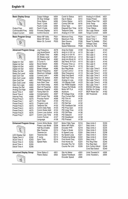
Basic Display Group
Output Freq b001Commanded Freq b002Output Current b003
Output Voltage b004DC Bus Voltage b005Drive Status b006Fault 1 Code b007Fault 2 Code b008Fault 3 Code b009Process Display b010Control Source b012
Contrl In Status b013Dig In Status b014Comm Status b015Control SW Ver b016Drive Type b017Elapsed Run Time b018Testpoint Data b019Analog In 0-10V b020
Analog In 4-20mA b021Output Power b022Output Powr Fctr b023Drive Temp b024Counter Status b025Timer Status b026Stp Logic Status b028Torque Current b029
Basic Program Group Motor NP Volts P031Motor NP Hertz P032Motor OL Current P033
Minimum Freq P034Maximum Freq P035Start Source P036Stop Mode P037Speed Reference P038
Accel Time 1 P039Decel Time 1 P040Reset To Defalts P041Voltage Class P042Motor OL Ret P043
Advanced Program Group
Digital In1 Sel A051Digital In2 Sel A052Digital In3 Sel A053Digital In4 Sel A054Relay Out Sel A055Relay Out Level A056Opto Out1 Sel A058Opto Out1 Level A059Opto Out2 Sel A061Opto Out2 Level A062Opto Out Logic A064Analog Out Sel A065Analog Out High A066Accel Time 2 A067Decel Time 2 A068Internal Freq A069Preset Freq 0 A070Preset Freq 1 A071Preset Freq 2 A072Preset Freq 3 A073Preset Freq 4 A074Preset Freq 5 A075Preset Freq 6 A076Preset Freq 7 A077
Jog Frequency A078Jog Accel/Decel A079DC Brake Time A080DC Brake Level A081DB Resistor Sel A082S Curve % A083Boost Select A084Start Boost A085Break Voltage A086Break Frequency A087Maximum Voltage A088Current Limit 1 A089Motor OL Select A090PWM Frequency A091Auto Rstrt Tries A092Auto Rstrt Delay A093Start At PowerUp A094Reverse Disable A095Flying Start En A096Compensation A097SW Current Trip A098Process Factor A099Fault Clear A100Program Lock A101Testpoint Sel A102Comm Data Rate A103Comm Node Addr A104Comm Loss Action A105Comm Loss Time A106Comm Format A107Language A108
Anlg Out Setpt A109Anlg In 0-10V Lo A110Anlg In 0-10V Hi A111Anlg In4-20mA Lo A112Anlg In4-20mA Hi A113Slip Hertz @ FLA A114Process Time Lo A115Process Time Hi A116Bus Reg Mode A117Current Limit 2 A118Skip Frequency A119Skip Freq Band A120Stall Fault Time A121Analog In Loss A12210V Bipolar Enbl A123Var PWM Disable A124Torque Perf Mode A125Motor NP FLA A126Autotune A127IR Voltage Drop A128Flux Current Ref A129PID Trim Hi A130PID Trim Lo A131PID Ref Sel A132PID Feedback Sel A133PID Prop Gain A134PID Integ Time A135PID Diff Rate A136PID Setpoint A137PID Deadband A138PID Preload A139
Stp Logic 0 A140Stp Logic 1 A141Stp Logic 2 A142Stp Logic 3 A143Stp Logic 4 A144Stp Logic 5 A145Stp Logic 6 A146Stp Logic 7 A147Stp Logic Time 0 A150Stp Logic Time 1 A151Stp Logic Time 2 A152Stp Logic Time 3 A153Stp Logic Time 4 A154Stp Logic Time 5 A155Stp Logic Time 6 A156Stp Logic Time 7 A157EM Brk Off Delay A160EM Brk On Delay A161MOP Reset Sel A162DB Threshold A163
Enhanced Program Group
LED Display Opt E201Digital Term 3 E202Accel Time 3 E203Decel Time 3 E204Accel Time 4 E205Decel Time 4 E206
Comm Write Mode E207Power Loss Mode E208Half Bus Enable E209Max Traverse E210Traverse Inc E211Traverse Dec E212P Jump E213Sync Time E214Speed Ratio E215
Motor Fdbk Type E216Motor NP Poles E217Encoder PPR E218Pulse In Scale E219Ki Speed Loop E220Kp Speed Loop E221Positioning Mode E222Find Home Freq E223Find Home Dir E224Encoder Pos Tol E225Counts Per Unit E226
Step Units 0 E230Step Units 1 E232Step Units 2 E234Step Units 3 E236Step Units 4 E238Step Units 5 E240Step Units 6 E242Step Units 7 E244Pos Reg Filter E246Pos Reg Gain E247Enh Control Word E248Cmd Stat Select E249
Advanced Display Group Drive Status 2 d301Fibers Status d302
Slip Hz Meter d303Speed Feedback d304Encoder Speed d306
Units Traveled H d308Units Traveled L d309

English-17
The PowerFlex 40P is designed so that start up is simple and efficient. The Program Group contains the most commonly used parameters.
Display Group Parameters
No. Parameter Min/Max Display/Optionsb001 [Output Freq] 0.00/ [Maximum Freq] 0.01 Hz
b002 [Commanded Freq] 0.00/ [Maximum Freq] 0.01 Hz
b003 [Output Current] 0.00/(Drive Amps × 2) 0.01 Amps
b004 [Output Voltage] 0/Drive Rated Volts 1 VAC
b005 [DC Bus Voltage] Based on Drive Rating 1 VDC
b006 [Drive Status] 0/1 (1 = Condition True) Bit 3 Bit 2 Bit 1 Bit 0Decelerating Accelerating Forward Running
b007-b009
[Fault x Code] F2/F122 F1
b010 [Process Display] 0.00/9999 0.01 – 1
b012 [Control Source] 0/112 Digit 2&3 = Speed Command Digit 1 = Start Command(See P038; 9 = “Jog Freq”) (See P036; 9 = “Jog”)
b013 [Contrl In Status] 0/1 (1 = Input Present) Bit 3 Bit 2 Bit 1 Bit 0DB Trans On Stop Input Dir/REV In Start/FWD In
b014 [Dig In Status] 0/1 (1 = Input Present) Bit 3 Bit 2 Bit 1 Bit 0Digital In 4 Digital In 3 Digital In 2 Digital In 1
b015 [Comm Status] 0/1 (1 = Condition True) Bit 3 Bit 2 Bit 1 Bit 0Comm Error DSI Option Transmitting Receiving
b016 [Control SW Ver] 1.00/99.99 0.01
b017 [Drive Type] 1001/9999 1
b018 [Elapsed Run Time] 0/9999 Hrs 1 = 10 Hrs
b019 [Testpoint Data] 0/FFFF 1 Hex
b020 [Analog In 0-10V] 0.0/100.0% 0.1%
b021 [Analog In 4-20mA] 0.0/100.0% 0.1%
b022 [Output Power] 0.00/(Drive Power × 2) 0.01 kW
b023 [Output Powr Fctr] 0.0/180.0 deg 0.1 deg
b024 [Drive Temp] 0/120 degC 1 degC
b025 [Counter Status] 0/9999 1
b026 [Timer Status] 0.0/9999 Secs 0.1 Secs
b028 [Stp Logic Status] 0/8 1
b029 [Torque Current] 0.00/(Drive Amps × 2) 0.01 Amps
Smart Start-Up with Basic Program Group Parameters
= Stop drive before changing this parameter.
No. Parameter Min/Max Display/Options DefaultP031 [Motor NP Volts] 20/Drive Rated Volts 1 VAC Based on Drive Rating
Set to the motor nameplate rated volts.
P032 [Motor NP Hertz] 15/500 Hz 1 Hz 60 Hz
Set to the motor nameplate rated frequency.
P033 [Motor OL Current] 0.0/(Drive Rated Amps× 2) 0.1 Amps Based on Drive Rating
Set to the maximum allowable motor current.
P034 [Minimum Freq] 0.00/500.0 Hz 0.01 Hz 0.00 Hz
Sets the lowest frequency the drive will output continuously.
P035 [Maximum Freq] 0.00/500.0 Hz 0.01 Hz 60.00 Hz
Sets the highest frequency the drive will output.
P036 [Start Source] 1/6 1 = “3-Wire”2 = “2-Wire”3 = “2-W Lvl Sens”4 = “2-W Hi Speed”5 = “Comm Port”6 = “Momt FWD/REV”
5
Sets the control scheme used to start the drive.
English-18
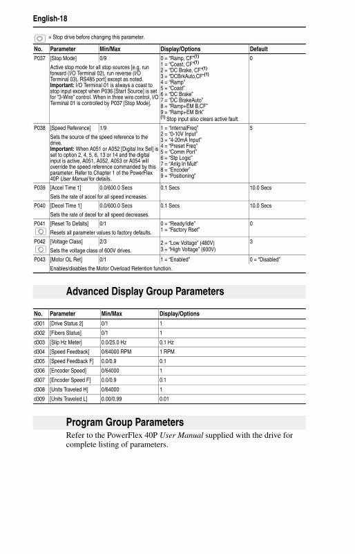
Refer to the PowerFlex 40P User Manual supplied with the drive for complete listing of parameters.
P037 [Stop Mode] 0/9 0 = “Ramp, CF”(1)
1 = “Coast, CF”(1)
2 = “DC Brake, CF”(1)
3 = “DCBrkAuto,CF”(1)
4 = “Ramp”5 = “Coast”6 = “DC Brake”7 = “DC BrakeAuto”8 = “Ramp+EM B,CF”9 = “Ramp+EM Brk”(1) Stop input also clears active fault.
0
Active stop mode for all stop sources [e.g. run forward (I/O Terminal 02), run reverse (I/O Terminal 03), RS485 port] except as noted.Important: I/O Terminal 01 is always a coast to stop input except when P036 [Start Source] is set for “3-Wire” control. When in three wire control, I/O Terminal 01 is controlled by P037 [Stop Mode].
P038 [Speed Reference] 1/9 1 = “InternalFreq”2 = “0-10V Input”3 = “4-20mA Input”4 = “Preset Freq”5 = “Comm Port”6 = “Stp Logic”7 = “Anlg In Mult”8 = “Encoder”9 = “Positioning”
5
Sets the source of the speed reference to the drive.Important: When A051 or A052 [Digital Inx Sel] is set to option 2, 4, 5, 6, 13 or 14 and the digital input is active, A051, A052, A053 or A054 will override the speed reference commanded by this parameter. Refer to Chapter 1 of the PowerFlex 40P User Manual for details.
P039 [Accel Time 1] 0.0/600.0 Secs 0.1 Secs 10.0 Secs
Sets the rate of accel for all speed increases.
P040 [Decel Time 1] 0.0/600.0 Secs 0.1 Secs 10.0 Secs
Sets the rate of decel for all speed decreases.
P041 [Reset To Defalts] 0/1 0 = “Ready/Idle”1 = “Factory Rset”
0
Resets all parameter values to factory defaults.
P042 [Voltage Class] 2/3 2 = “Low Voltage” (480V)3 = “High Voltage” (600V)
3
Sets the voltage class of 600V drives.
P043 [Motor OL Ret] 0/1 1 = “Enabled” 0 = “Disabled”
Enables/disables the Motor Overload Retention function.
= Stop drive before changing this parameter.
No. Parameter Min/Max Display/Options Default
Advanced Display Group Parameters
No. Parameter Min/Max Display/Options
d301 [Drive Status 2] 0/1 1
d302 [Fibers Status] 0/1 1
d303 [Slip Hz Meter] 0.0/25.0 Hz 0.1 Hz
d304 [Speed Feedback] 0/64000 RPM 1 RPM
d305 [Speed Feedback F] 0.0/0.9 0.1
d306 [Encoder Speed] 0/64000 1
d307 [Encoder Speed F] 0.0/0.9 0.1
d308 [Units Traveled H] 0/64000 1
d309 [Units Traveled L] 0.00/0.99 0.01
Program Group Parameters
English-19
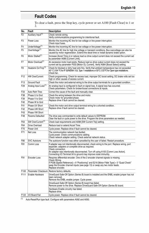
To clear a fault, press the Stop key, cycle power or set A100 [Fault Clear] to 1 or 2.
Fault Codes
No. Fault DescriptionF2 Auxiliary Input(1) Check remote wiring.
Verify communications programming for intentional fault.F3 Power Loss Monitor the incoming AC line for low voltage or line power interruption.
Check input fuses.F4 UnderVoltage(1) Monitor the incoming AC line for low voltage or line power interruption.F5 OverVoltage(1) Monitor the AC line for high line voltage or transient conditions. Bus overvoltage can also be
caused by motor regeneration. Extend the decel time or install dynamic brake option.F6 Motor Stalled(1) Increase [Accel Time x] or reduce load so drive output current does not exceed the current set
by parameter A089 [Current Limit].F7 Motor Overload(1) An excessive motor load exists. Reduce load so drive output current does not exceed the
current set by parameter P033 [Motor OL Current]. Verify A084 [Boost Select] setting.F8 Heatsink OvrTmp(1) Check for blocked or dirty heat sink fins. Verify that ambient temperature has not exceeded
40°C (104°F) for IP 30/NEMA 1/UL Type 1 installations or 50°C (122°F) for Open type installations.Check fan.
F12 HW OverCurrent Check programming. Check for excess load, improper DC boost setting, DC brake volts set too high or other causes of excess current.
F13 Ground Fault Check the motor and external wiring to the drive output terminals for a grounded condition.F29 Analog Input Loss(1) An analog input is configured to fault on signal loss. A signal loss has occurred.
Check parameters. Check for broken/loose connections at inputs.F33 Auto Rstrt Tries Correct the cause of the fault and manually clear.F38 Phase U to Gnd Check the wiring between the drive and motor.
Check motor for grounded phase.Replace drive if fault cannot be cleared.
F39 Phase V to GndF40 Phase W to GndF41 Phase UV Short Check the motor and drive output terminal wiring for a shorted condition.
Replace drive if fault cannot be cleared.F42 Phase UW ShortF43 Phase VW ShortF48 Params Defaulted The drive was commanded to write default values to EEPROM.
Clear the fault or cycle power to the drive. Program the drive parameters as needed.F63 SW OverCurrent(1) Check load requirements and A098 [SW Current Trip] setting.F64 Drive Overload Reduce load or extend Accel Time.F70 Power Unit Cycle power. Replace drive if fault cannot be cleared.F71 Net Loss The communication network has faulted.
Cycle power. Check communications cabling.Check network adapter setting. Check external network status.
F80 SVC Autotune The autotune function was either cancelled by the user of failed. Restart procedure.F81 Comm Loss If adapter was not intentionally disconnected, check wiring to the port. Replace wiring, port
expander, adapters or complete drive as required.Check connection.An adapter was intentionally disconnected. Turn off using A105 [Comm Loss Action].Connecting I/O Terminal 04 to ground may improve noise immunity.
F91 Encoder Loss Requires differential encoder. One of the 2 encoder channel signals is missing.Check Wiring.If P038 [Speed Reference] = 9 “Positioning” and E216 [Motor Fdbk Type] = 5 “Quad Check” swap the Encoder channel inputs (see page 13) or swap any two motor leads.Replace encoder.
F100 Parameter Checksum Restore factory defaults.F111 Enable Hardware DriveGuard Safe-Off Option (Series B) board is installed and the ENBL enable jumper has not
been removed.Remove the ENBL enable jumper. Cycle power.DriveGuard Safe-Off Option (Series B) board has failed.Remove power to the drive. Replace DriveGuard Safe-Off Option (Series B) board.Hardware Enable circuitry has failed.Replace drive.
F122 I/O Board Fail Cycle power. Replace drive if fault cannot be cleared.(1) Auto-Reset/Run type fault. Configure with parameters A092 and A093.
English-20
U.S. Allen-Bradley Drives Technical SupportTel: (1) 262.512.8176, Fax: (1) 262.512.2222, Email: [email protected], Online: www.ab.com/support/abdrives
Publication 22D-QS001C-EN-P – October 2008Supersedes May 2007 Copyright © 2008 Rockwell Automation, Inc. All rights reserved.
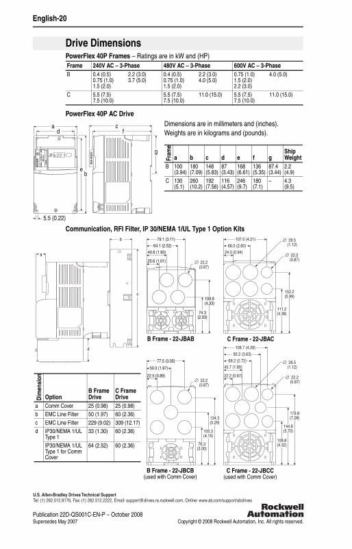
PowerFlex 40P Frames – Ratings are in kW and (HP)
PowerFlex 40P AC DriveDimensions are in millimeters and (inches).Weights are in kilograms and (pounds).
Communication, RFI Filter, IP 30/NEMA 1/UL Type 1 Option Kits
Drive Dimensions
Frame 240V AC – 3-Phase 480V AC – 3-Phase 600V AC – 3-PhaseB 0.4 (0.5)
0.75 (1.0)1.5 (2.0)
2.2 (3.0)3.7 (5.0)
0.4 (0.5)0.75 (1.0)1.5 (2.0)
2.2 (3.0)4.0 (5.0)
0.75 (1.0)1.5 (2.0)2.2 (3.0)
4.0 (5.0)
C 5.5 (7.5)7.5 (10.0)
5.5 (7.5)7.5 (10.0)
11.0 (15.0) 5.5 (7.5)7.5 (10.0)
11.0 (15.0)
Fram
e
a b c d e f gShip Weight
B 100(3.94)
180(7.09)
148(5.83)
87(3.43)
168(6.61)
136(5.35)
87.4(3.44)
2.2(4.9)
C 130(5.1)
260(10.2)
192(7.56)
116(4.57)
246(9.7)
180(7.1)
– 4.3(9.5)
c
gRUNREV
FAULT
RUNREV
FAULT
ad
eb
5.5 (0.22)
f
20A
-DG
01
111.2(4.38)
152.2(5.99)
107.0 (4.21)66.0 (2.60)
∅ 22.2 (0.87)
∅ 28.5 (1.12)
24.0 (0.94)
74.3(2.93)
109.9(4.33)
64.1 (2.52)79.1 (3.11)
∅ 22.2 (0.87)
∅ 22.2 (0.87)
25.6 (1.01)
40.6 (1.60)
76.3(3.00)
105.3(4.15)
134.3(5.29)
50.0 (1.97)
77.5 (3.05)
22.5 (0.89)
45.7 (1.80)
109.8(4.32)
144.8(5.70)
179.8(7.08)
69.2 (2.72)92.2 (3.63)108.7 (4.28)
22.2 (0.87) ∅ 22.2 (0.87)
∅ 28.5 (1.12)
a
d
b
c
B Frame - 22-JBAB C Frame - 22-JBAC
B Frame - 22-JBCB(used with Comm Cover)
C Frame - 22-JBCC(used with Comm Cover)
Dim
ensi
on
OptionB Frame Drive
C Frame Drive
a Comm Cover 25 (0.98) 25 (0.98)b EMC Line Filter 50 (1.97) 60 (2.36)c EMC Line Filter 229 (9.02) 309 (12.17)d IP30/NEMA 1/UL
Type 133 (1.30) 60 (2.36)
IP30/NEMA 1/UL Type 1 for Comm Cover
64 (2.52) 60 (2.36)